

Page 1
EPSON COLOR INKJET PRINTER
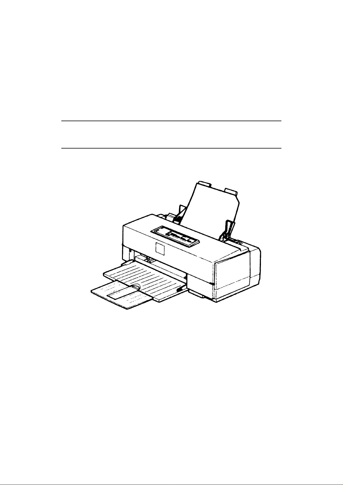
Stylus-500
SERVICE MANUAL
EPSON
4006359
Page 2

PREFACE
This document provides supplementary information to describe the EPSON Stylus COLOR 500, which is a
follow-on version of the EPSON Stylus COLOR II. Therefore, you must refer to this information in conjunction
with the EPSON Stylus COLOR II Service Manual for details on any subjects common to both printers.
-i-
Page 3
EPSON Stylus COLOR 500 Service Manual Product Description
1.1 FEATURES
The EPSON Stylus COLOR 500 is a small-footprint, personal-use color ink jet printer. The major new
features of this printer are:
❏ Newly developed black and color inks
High-quality black printing
Deep color printing
❏ Simple control panel operation
3 No lock switches
4 LED lamps
❏ A new design for the left guide edge locking mechanism in the ASF (auto sheet feeder)
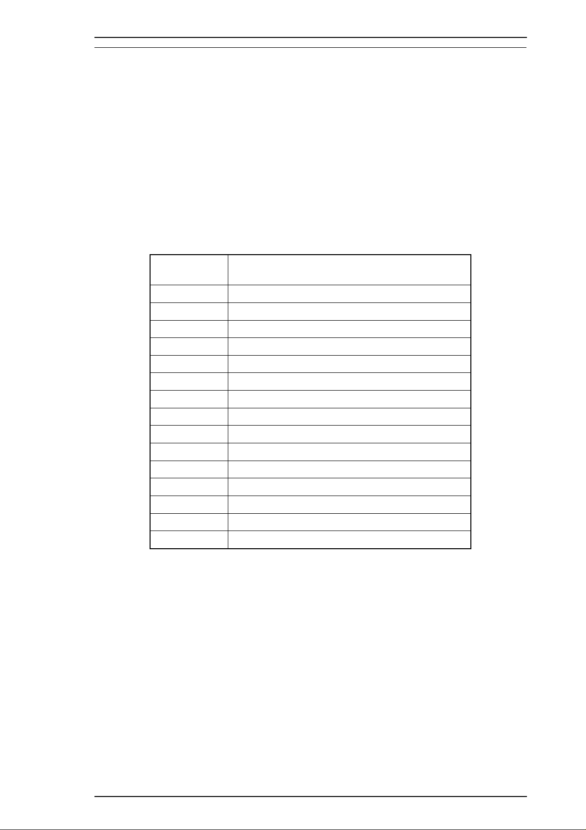
Table 1-1. Consumables
Model Description
S020093
S020097 Color ink cartridge
S041059
S041025
S041060
S041061 EPSON premium paper for 720 dpi printing (A4)
S041026
S041062 EPSON premium paper for 360 dpi printing (Letter)
S041067
S041048
S041071
S041072 High-quality glossy paper (Letter)
S041063
S041064
S041054
Monochrome ink cartridge
EPSON premium paper for 360 dpi printing (A4)
EPSON premium paper for 360 dpi printing (A4)
EPSON premium paper for 360 dpi printing (Letter)
EPSON premium paper for 720 dpi printing (A4)
EPSON premium paper for 360 dpi printing (Legal)
EPSON premium paper for 360 dpi printing (Legal)
High-quality glossy paper (A4)
Transparency film (A4)
Transparency film (Letter)
EPSON premium card stock for 720 dpi printing (A6)
Rev.A 1-1
Page 4
Product Description EPSON Stylus COLOR 500 Service Manual
1.2 SPECIFICATIONS
This section provides detailed information about the EPSON Stylus COLOR 500.
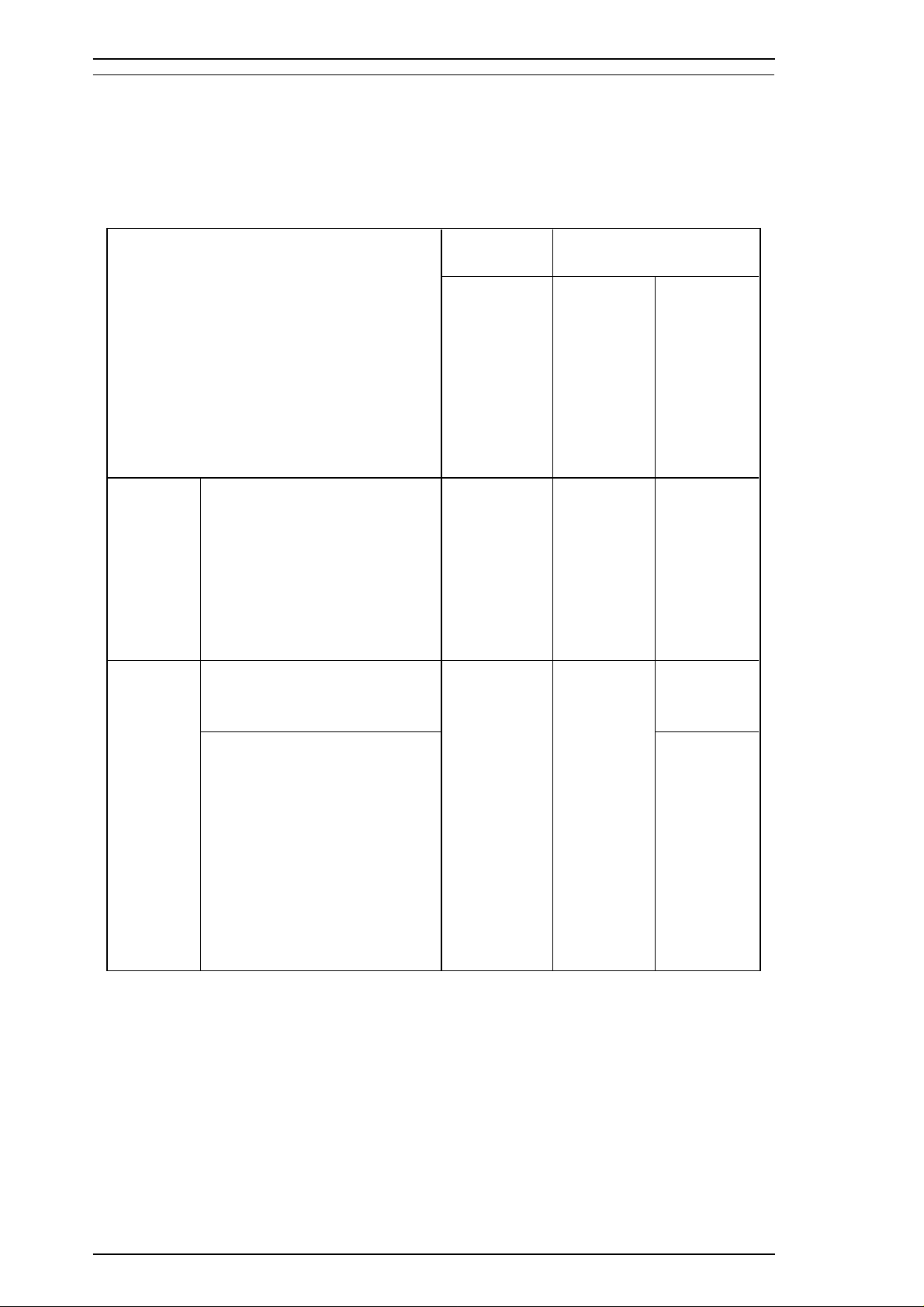
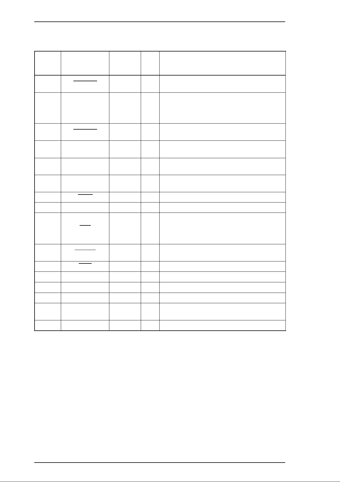
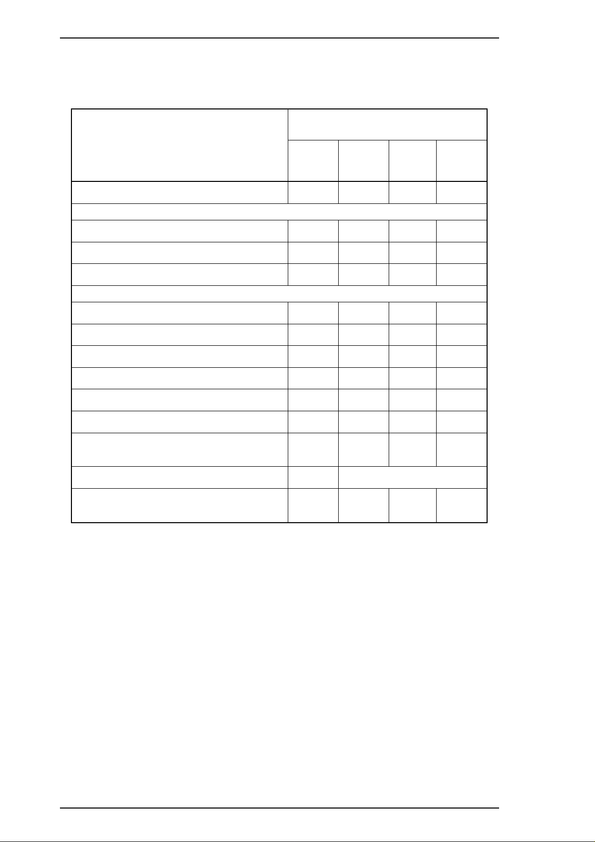
1.2.1 Printing Specification Table 1-2. Character Tables and Typefaces
Bitmap fonts Scalable fonts
EPSON
Roman
EPSON
Character Tables
Sans Serif
EPSON
Courier
EPSON
Prestige
EPSON
Script
EPSON
Roman
EPSON
Sans Serif
EPSON
Roman T
EPSON
Sans Serif H
Standard
version
NLSP
version
Italic
PC437 (U.S., Standard Europe)
PC850 (Multilingual)
PC860 (Portuguese)
PC861 (Icelandic)
PC863 (Canadian-French)
PC865 (Nordic)
BRASCII
Abicomp
Italic
PC437 (U.S., Standard Europe)
PC850 (Multilingual)
PC437 Greek
PC852 (East Europe)
PC853 (Turkish)
PC855 (Cyrillic)
PC857 (Turkish)
PC866 (Russian)
PC869 (Greek)
MAZOWIA (Poland)
Code MJK (CSFR)
ISO 8859-7(Latin/Greek)
ISO Latin 1T (Turkish)
Bulgaria (Bulgaria)
Supported Supported Supported
Supported
Supported Supported
Not
supported
1.2.2 Electric Specification
Power consumption 120v Approx.18W (ISO10561 Letter pattern)
220-240V Approx. 18W (ISO10561 Letter pattern)
Energy Star compliant
1-2 Rev.B
Page 5
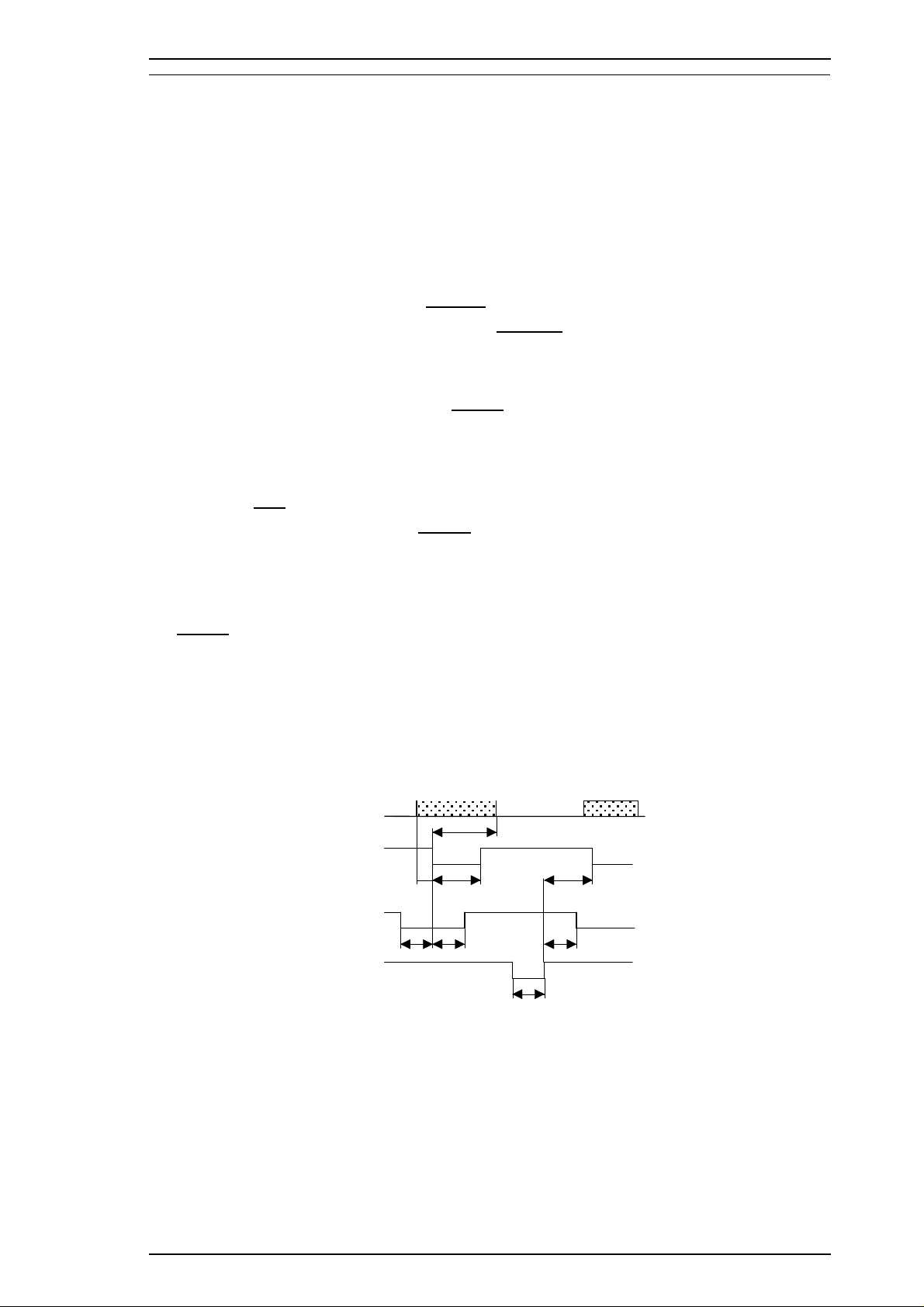
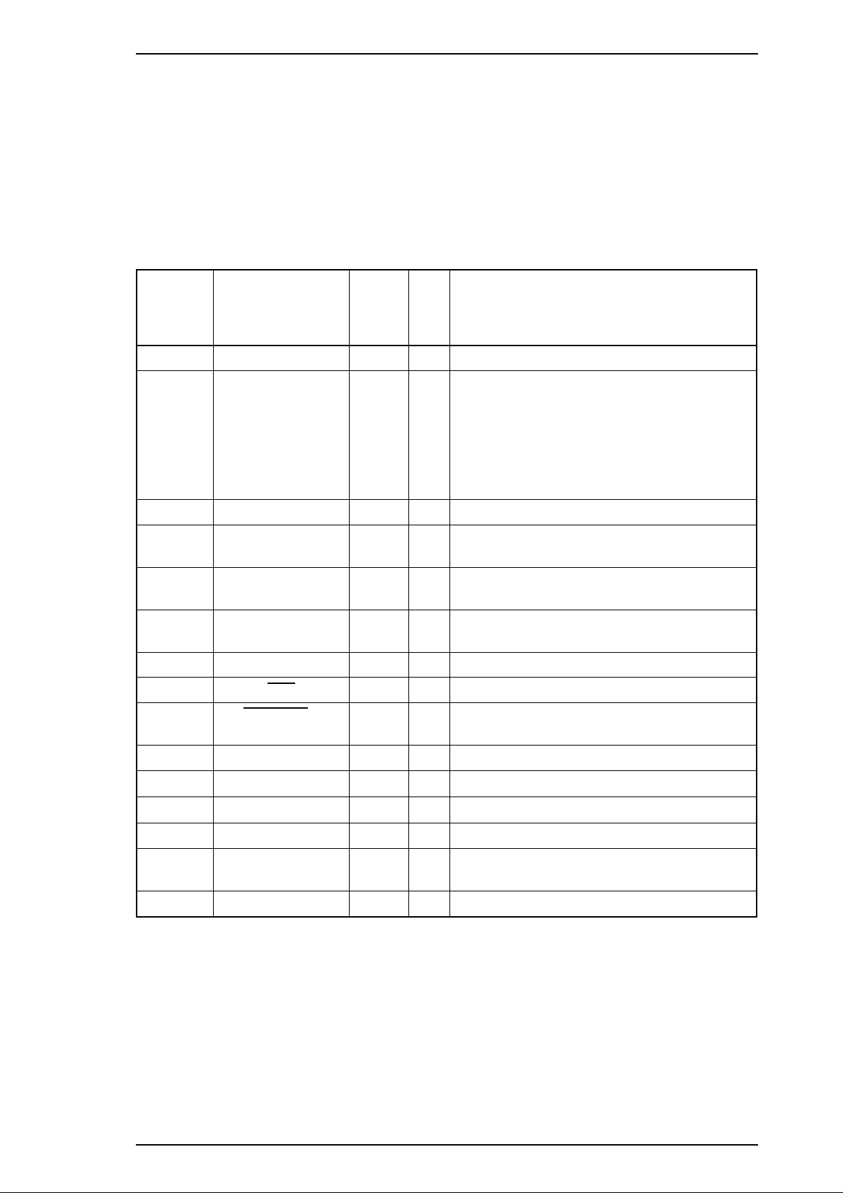
DATA (n)
DATA
-STROBE
BUSY
-ACKNLG
500 ns (min.)
500 ns (min.) 500 ns (min.)
0 (min.)
0 (min.)
500 ns ~10 µs
0 (min.) 500 ns (max.)
DATA (n+1)
* : The rise and fall time of every output signal must be less than 120 ns.
The rise and fall time of every input signal must be less than 200 ns.
EPSON Stylus COLOR 500 Service Manual Product Description
1.3 INTERFACES
1.3.1 Hardware Interfaces
This section fully describes the EPSON Stylus COLOR 500 interfaces. The printer offers both a parallel and
serial interface, standard.
1.3.1.1 Parallel Interface
Forward Channel
Transmission mode: 8 bit parallel, IEEE-1284 compatibility mode
Synchronization:
Handshaking: BUSY and
Signal level: TTL compatible level (IEEE-1284 level 1 device)
Connector type: 57-30360 (Amphenol or equivalent)
STROBE pulse
ACKNLG signal
The BUSY signal is set to HIGH before either
ERROR is set LOW or PE is set HIGH, and BUSY is held
HIGH until all these signals return to the inactive state. The BUSY signal goes HIGH in the following cases:
• During data entry (See data transmission timing).
• When the input data buffer is full.
• When the
• During a printer error condition (see
INIT signal is at a LOW level, or during hardware initialization.
ERROR signal).
• During self-test printing.
• In default setting mode.
• When the parallel interface is not selected.
The
ERROR signal is LOW when the printer is in one of the following conditions:
• Printer hardware error (fatal error condition).
• Paper-out error.
• Release lever operation error.
The PE signal is HIGH during a paper-out error.
Rev.A 1-3
Figure 1-1. Data Transmission Timing
Page 6
Product Description EPSON Stylus COLOR 500 Service Manual
Table 1-4 shows the connector pin assignments and signals for the 8-bit parallel interface.
Table 1-3. Connector Pin Assignments and Signals (Forward Channel)
Pin No. Signal Name
1
2 ~ 9 DATA 0 ~ 7 20 ~ 27
10 ACKNLG 28
11 BUSY 29
12 PE 28 O
13 SLCT 28 O
14
15 NC — — Not connected.
31
STROBE 19 I
AFXT 30 I
INIT 30 I
Return
GND Pin
I/O Description
This is strobe pulse. Reading of data is
performed at the falling edge of this pulse.
Signals DATA0 ~ DATA7 represent data bits 0
to 7, respectively. When a DATA signal is
I
HIGH, the data is logical 1 and when LOW,
data is logical 0.
This signal is a negative pulse indicating that
O
the printer can accept more data.
When this signal is HIGH, the printer cannot
O
receive data.
When this signal is HIGH, the printer detects a
paper-out error.
This signal is always HIGH when the printer is
powered on.
The falling edge of a negative pulse or a LOW
signal on this line causes the printer to
initialize. A 50 µs pulse, minimum, is
necessary.
32
36
18 Logic H —
35 +5 V —
17 Chassis GND —
16, 33
19 - 30
15, 34 NC —
ERROR 29
SLIN 30
GND —
When this signal is LOW, the printer detects an
O
error.
I
Not used.
O
Pulled up to +5 V via 3.9 KΩ resistor.
O
Pulled up to +5 V via 3.3 KΩ resistor.
—
Chassis ground.
—
Signal ground.
—
Not used.
1-4 Rev.B
Page 7
EPSON Stylus COLOR 500 Service Manual Product Description
Reverse Channel
Transmission mode: IEEE-1284 nibble mode.
Connector: See forward channel.
Synchronization: Refer to the IEEE-1284 specification.
Handshaking: Refer to the IEEE-1284 specification.
Data transmission timing: Refer to the IEEE-1284 specification.
Signal level: Refer to the IEEE-1284 specification.
Table 1-4. Connector Pin Assignments and Signals (Reverse Channel)
Return
Pin No. Signal Name
1 Host Clk 19 I Host clock signal.
2 ~ 9 DATA0 ~ 7 20 - 27 I
GND
Pin
I/O Description
DATA0 ~ DATA7 signals represent data bits 0
to 7, respectively. Each signal is at a HIGH
level when data is logical 1 and at a LOW
level when data is logical 0.
These signals are used to transfer the
extensibility request values (described in
IEEE-P1284) to the printer.
10 PtrClk 28 O Printer clock signal.
11
12
13
14 Host Busy 30 I Host busy signal.
31
32
36 1284-Active 30 I Active signal for IEEE-P1284 mode.
18 Logic-H
35 +5 V — O
17 Chassis GND —
16, 33
19 - 30
15, 34 NC — — Not connected.
Ptr Busy /
Data Bits 3, 7
Ack Data Req /
Data Bits 2, 6
Xflag / Data Bits 1,
5
INIT 30 I Not used.
Data Avail /
Data Bits 0, 4
GND — — Signal ground.
29 O
28 O
28 O
29 O
—
Printer busy signal and reverse channel
transfer data 3 or 7.
Acknowledge data request signal and reverse
channel transfer data bit 2 or 6.
X-flag signal and reverse channel transfer
data bits 1 or 5.
Data available and reverse channel data bits
0 or 4.
O
Pulled up to +5 V via 3.9K Ω resistor.
Pulled up to +5 V via 3.3K Ω resistor.
—
Chassis ground.
Note: I / O refers to direction of the signal flow from the view of the printer.
Rev.A 1-5
Page 8

Product Description EPSON Stylus COLOR 500 Service Manual
Extensibility
Request
Device ID The printer sends following device ID string when it is requested:
The printer responds affirmatively when the extensibility request values are 00H or 04H.
That means:
00H: Request Nibble Mode Reverse Channel Transfer
04H: Request Device ID;
Return Data Using Nibble Mode Channel Transfer.
ESC/P2 mode X24E mode
00H 3AH 00H 3BH
MFG: EPSON; MFG: EPSON;
CMD:ESCPL2-00 CMD: PRPXL24-00
MDL: Stylus COLOR 500; MDL: Stylus COLOR 500;
CLS: PRINTER; CLS: PRINTER;
Note: 00H denotes a hexadecimal value of zero.
1-6 Rev.B
Page 9
EPSON Stylus COLOR 500 Service Manual Product Description
1.4 POWER AND CONTROL PANEL OPERATIONS
This section describes the controls used to operate the EPSON Stylus COLOR 500.
1.4.1 Power Switch
The Power switch is in the right rear corner of the printer.
CAUTION
This switch is for the primary power supply circuit. Therefore, you must put the printer in the
waiting condition to make it cap the head before power off.
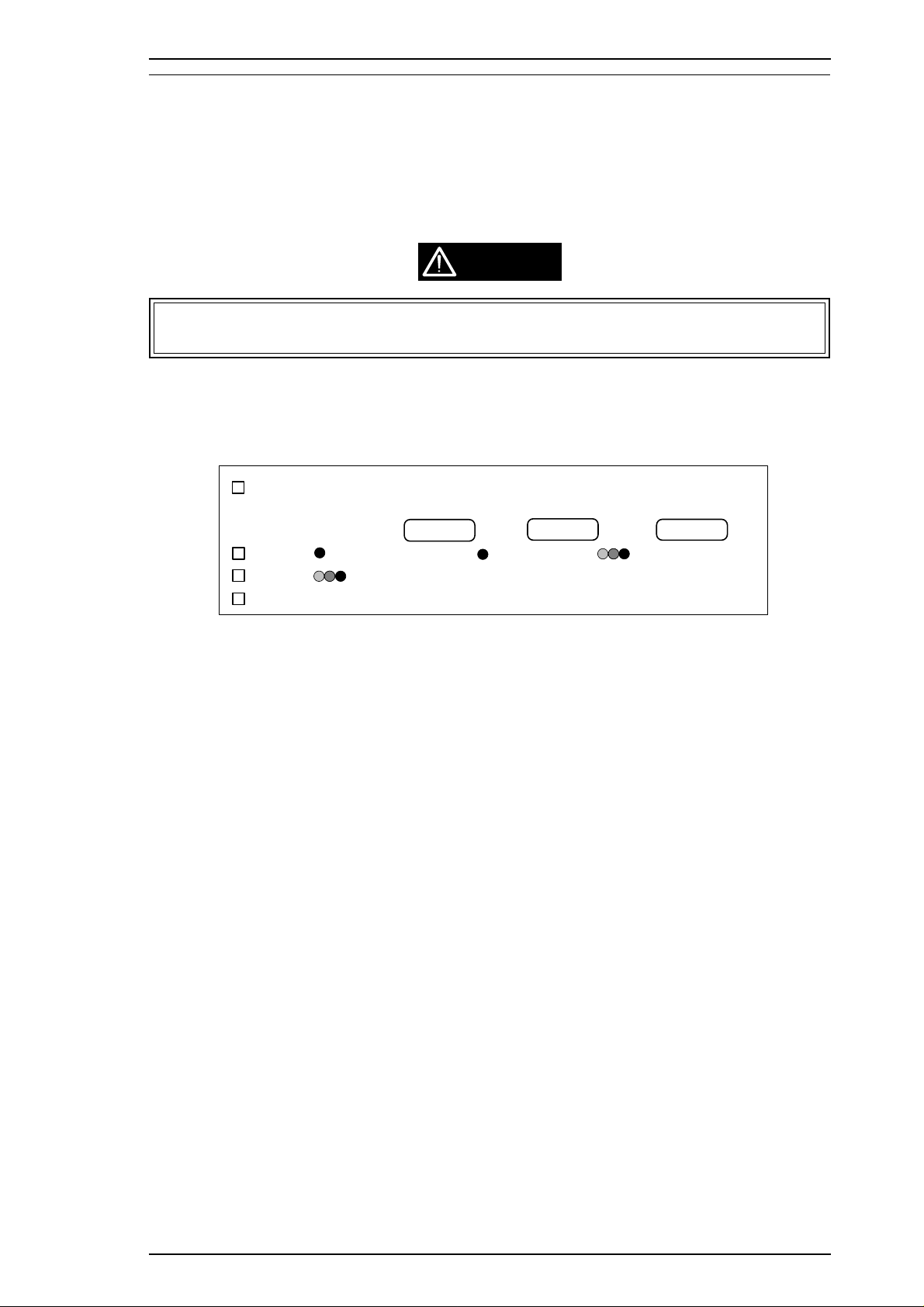
1.4.2 CONTROL PANEL
The control panel for this printer is in the center of the upper case. The panel has 3 non-lock type pushbuttons
and 4 LEDs.
Power
Ink Out
Ink Out
Paper Ou t
Cleaning
Figure 1-2. Panel Appearance
1.4.2.1 Buttons and Indicators
Cleaning (Black)
This button makes the printer perform the black head cleaning.
Cleaning (Color)
This button makes the printer perform the color head cleaning.
Load / Eject
This button loads and ejects paper.
❏ After you hold down Load / Eject for 3 seconds, the printer carriage moves to the ink cartridge
installation position. When Load / Eject is pressed again, the CR returns to the home position.
Cleaning Load / Eject
Rev.A 1-7
Page 10

Product Description EPSON Stylus COLOR 500 Service Manual
Indicators
Power
Lights when the printer’s Power switch is On, and AC power is supplied.
Ink Out (Black)
Lights when there is no ink in the black ink cartridge, and blinks when the black ink cartridge is low.
Ink Out (Color)
Lights when there is no ink in the color ink cartridge, and blinks when the color ink cartridge is low.
Paper Out
Lights during a paper out, and blinks during a paper jam.
1-8 Rev.B
Page 11
EPSON Stylus COLOR 500 Service Manual Product Description
1.4.3 Panel Functions at Power On
The table below gives functions for different button combinations at power on.
Table 1-5. Panel Functions at Power On
Button Pressed along with Power On
Cleaning (Black) Starts demonstration print.
Load / Eject Enters the default setting mode.
Load / Eject + Cleaning (Black) Enters the printer adjustment mode.
Cleaning (Color) Starts LQ self-test printing.
Load / Eject + Cleaning (Color) Enters the ink smudge prevention mode.
Cleaning (Black) + Cleaning
(Color)
Load / Eject + Cleaning (Black)
+ Cleaning (Color),
Load / Eject less than 3 seconds
Note : 1. “+” indicates pressing one button while holding the other button(s) down.
2. EEPROM and Timer IC resets are for use by authorized servicers only.
Enters hex dump mode.
Enters reset mode for the EEPROM and Timer IC.
(Factory and service use only.)
Rev.A 1-9
Page 12
Product Description EPSON Stylus COLOR 500 Service Manual
1.4.4 Printer Conditions and Status
This section describes how the printer indicates status and error conditions using LEDs.
Table 1-6. Indicator Status
LEDs
Printer Status
Power
Power on condition On — — —
Data exist Blinks — — —
Ink sequence Blinks — — —
Ink cartridge change mode Blinks — — —
Paper out — — — On
Ink Out
(Black)
Ink Out
(Color)
Paper
Out
Paper jam condition — — — Blinks
No ink cartridge or Ink end (black) — On — —
Ink level low (black) — Blinks — —
No ink cartridge or Ink end (color) — — On —
Ink level low (color) — — Blinks —
Maintenance request
EEPROM and timer reset — On for 1 second only
Fatal error
Blinks
Rapidly
Blinks
Rapidly
Blinks
Rapidly
On On On
Blinks
Rapidly
Notes: When transparency paper is selected, unidirectional printing is selected.
— Does not affect status listed in the left-hand column.
Blinks
Rapidly
1-10 Rev.B
Page 13
START
The printer pr ints out:
ROM Version No.
Protect Counter Value
Cleaning
(Black)
Print current settings.
Select the menu
for setting d efau lts?
Select the menu :
Cleaning (Black) button
Set the menu :
Cleaning (Color) button.
Power off the printer
END
Hold down the
Load / Eject
button with pow er on.
Use the language
setting mode.
Select language
for setting defaults?
Cleaning
(Color)
Cleaning
(Black)
Change the value :
C leaning (Blac k) button
Set the value :
Cl ean ing (Co lor ) bu tton .
Continue setting
defaults?
Yes
No
EPSON Stylus COLOR 500 Service Manual Product Description
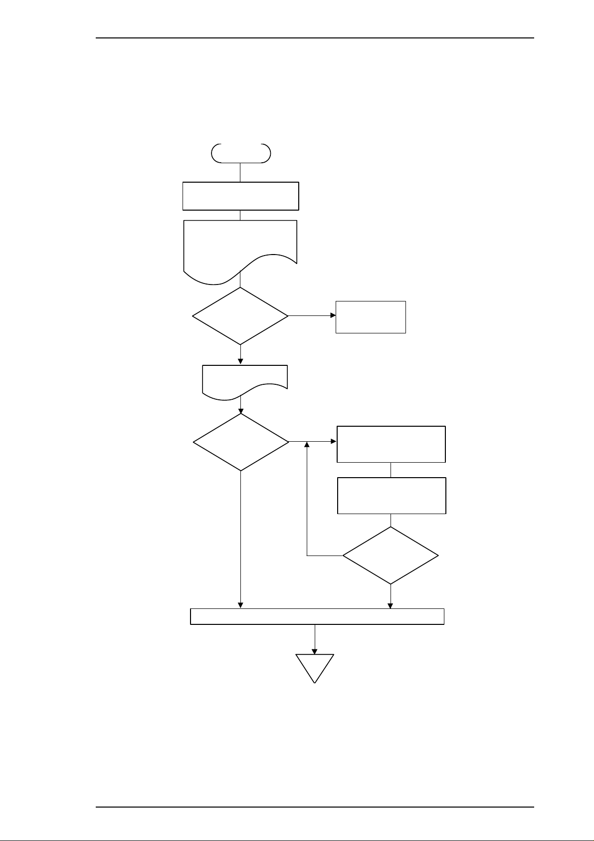
1.4.5 Default Settings
This printer has user-selectable default settings, which it refers to at initialization. The default (and factory)
settings are listed in the table on the next page.
1.4.5.1 Setting Method
The method of setting defaults is shown in the flowchart below.
Figure 1-3. Default Setting Flowchart
Rev.A 1-11
Page 14
Product Description EPSON Stylus COLOR 500 Service Manual
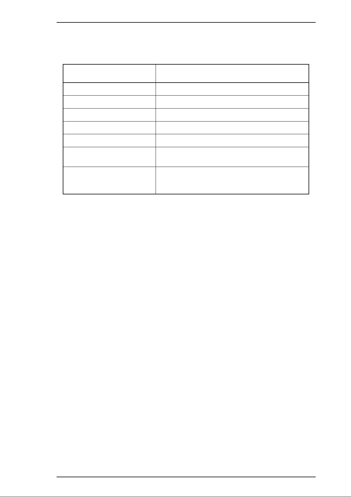
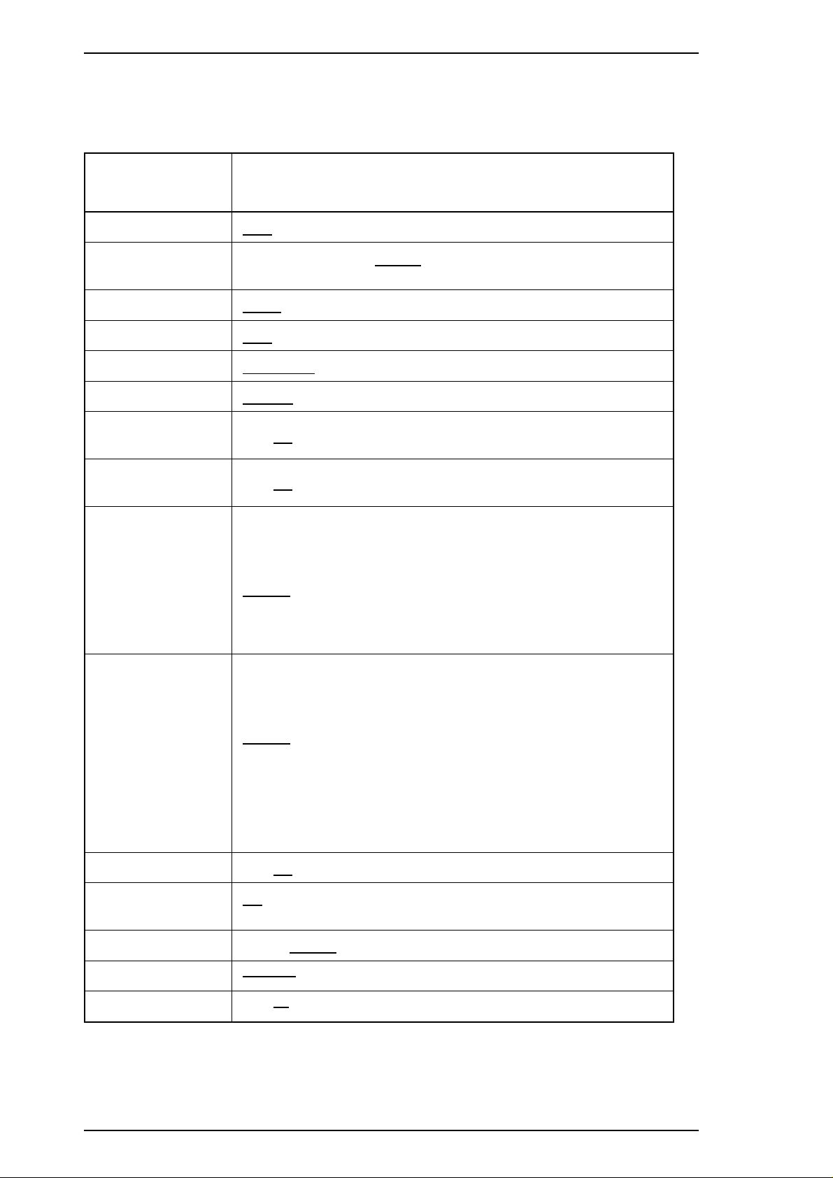
1.4.5.2 Setting Menus
The default setting menus are:
Table 1-7. Default Settings
Menus
Print direction
Font
Pitch
I/F mode
Auto I/F wait mode
Software
Auto CR
(IBM mode only)
AGM
(IBM mode only)
Character tables
(standard version)
Settings
(Underlines Indicate Factory Default Settings)
Auto / Bi-D / Uni-D
Roman / Sans Serif /
Courier / Prestige / Script / Roman T /
Sans Serif H
10 cpi / 12 cpi / 15 cpi / 17.1 cpi / 20 cpi / Proportional
Auto / Parallel / Serial
10 seconds / 30 seconds
ESC/P2 / IBM X24E
On /
Off
Off
On /
Italic U.S.A. Italic France
Italic Germany Italic U.K.
Italic Denmark Italic Sweden
Italic Italy Italic Spain 1
PC 437 PC 850
PC 860 PC 863
PC 865 PC 861
BRASCII Abicomp
Italic U.S.A. Italic France
Italic Germany Italic U.K.
Italic Denmark Italic Sweden
Italic Italy Italic Spain 1
Character tables
(NLSP version)
PC 437 PC 437 Greek
PC 850 PC 853
PC 855 PC 852
PC 857 PC 866
PC 869 MAZOWIA
Code MJK ISO 8859-7
ISO Latin 1T Bulgaria
Auto line feed On /
Network I/F mode
Loading position 3 mm /
Thick paper
Economy mode
Note *1. Other settings are set using special commands for the EEPROM.
Off
Off: Used in standalone environment
On: Used in network environment
8.5 mm / Others *
Envelopes / Index cards (portrait)
Off
On /
1
1-12 Rev.B
Page 15

EPSON Stylus COLOR 500 Service Manual Product Description
1.5 INK CARTRIDGE SPECIFICATIONS
Black
Type Exclusive cartridge
Model S020093
Color Black
Print capacity 620 pages/ A4 (LQ Roman EQMAtext)
Ink Life 2 years from production
Storage temperature 20 °C~40°C (–4° F ~ 104° F)
Storage, less than a month at 40 °C (104° F)
–30 °C~40°C (86° F ~ 104°F)
Packing storage, less than a month at 40 °C (104° F)
–30 °C~60°C (86° F ~ 140°F)
Transit, under 120 hours at 60° C(140°F)
and less than a month at 40° C (104° F )
Dimensions 19.8 mm (W) × 52.7 mm (D) × 38.5 mm (H)
0.8" (W) x 2.1" (D) x 1.5" (H)
Color
Type Exclusive cartridge
Model S020097
Color Magenta, cyan, yellow
Print capacity 320 pages /A4 (360 dpi, 5% duty, each color)
Ink Life 2 years from production
Storage temperatures –20°C~40°C(–4°F ~ 104°F)
Storage, less than a month at 40° C (104° F)
–30° C~40°C(86°F ~ 104° F)
Packing storage, less than a month at 40° C (104° F)
–30° C~60°C(86°F ~ 140° F)
Transit, less than 120 hours at 60 °C (140° F)
and less than a month at 40° C (104° F )
Dimensions 42.9 mm (W) × 56.8 mm (D) × 38.5 mm (H)
1.7" (W) x 2.2" (D) x 1.5" (D)
Rev.A 1-13
Page 16

Product Description EPSON Stylus COLOR 500 Service Manual
1.6 MAIN COMPONENTS
The main components of the EPSON Stylus COLOR 500 are designed for easy removal and repair. The main components are:
❏ Main Board (C161 MAIN)
❏ Power Supply Board (C160 PSB/PSE)
❏ Panel Board (C161 PNL)
❏ Mechanism
❏ Housing
1.6.1 Main Board (C161 MAIN)
This board consists of a CPU (TMP95C061F), a gate array (E05B12), ROM (CG), PROM, DRAM, EEPROM, motor driver ICs,
printhead driver circuits, etc.
1.6.2 Power Supply Board (C160 PSB/PSE)
This power supply board is the same as the one used for the Stylus Color IIs. This board consists of a transformer, a switching FET,
regulator IC, diode bridge, etc. This board has two ratings for input AC voltages.
1-14 Rev.B
Page 17

Normal
state
Ejecting
state
Vibration Plate
Vibration Plate
Cavity
Nozzle
Piezo
Piezo
Cavity
EPSON Stylus COLOR 500 Service Manual Operation Principles
2.1 OVERVIEW
This section describes operating principles of the EPSON Stylus COLOR 500 printer mechanism and
electrical circuits.
2.2 OPERATING PRINCIPLES OF THE PRINTER MECHANISM
2.2.1 Principles of the Printing Operation
The printhead operates in one of two modes to eject ink from each nozzle:
❏ Normal state
No electrical charge is applied to the piezoelectric element attached to the back of the cavity, and
pressure inside the cavity is kept at a constant level.
❏ Ejecting state
The head data signal is applied to the specific nozzle control line to select the active nozzle for printing,
and the piezoelectric element is gradually charged by the drive voltage. Charging the piezoelectric
element bends the vibration plate to compress the cavity. Then, ink is ejected from the nozzle.
Figure 2-1. Principles of the Printing Operation
When the ink charge or printhead cleaning operation is performed, ink in the cavity is vacuumed out with a
pump mechanism. During printing, on the other hand, ink is simultaneously supplied from the ink cartridge
and ejected from the nozzle, depending on changes in the volume of the cavity.
A thermistor is attached to the side of the color printhead driver board to monitor the temperature, because the
viscosity of the ink varies, depending on the temperature. The detected temperature level is fed back to the
printhead drive voltage control circuit to change the time of the Tc pulse.
Rev.A 2-1
Page 18

Operating Principles EPSON Stylus COLOR 500 Service Manual
2.3 OPERATING PRINCIPLES OF THE ELECTRICAL CIRCUITS
The EPSON Stylus COLOR 500 contains the following circuit board units:
❏ C161 MAIN / C198 MAIN Board (main control circuit board)
❏ C160 PSB/PSE Board (power supply circuit board). This board is the same as for the Stylus
COLOR.
❏ C161 PNL (control panel board)
In addition to the circuit boards above, part of the printhead driver circuit is built on a separate circuit board
installed in the carriage unit; the printhead is attached directly to this board. The figure below shows a block
diagram of the electrical circuitry.
2.3.1 Operating Principles of the Main Control Circuit
The main control circuit for this printer is the C161 MAIN Board. This circuit is controlled by a 16-bit
TMP96C061AF CPU (IC1), running at a 12.5 MHz internal clock (25 MHz external clock). A 4M DRAM
(CAS method) on this board is controlled by the CPU itself. The CPU manages the serial interface control
(RS-422 for Mac).
C198 MAIN board equips with the hybrid IC for monochrome head common driver circuit.
Gate array E05B12 (IC2) manages printhead driver control, the external Centronics
panel, and the motor control. The main board also is equipped with a 93C46 EEPROM (IC11) to store certain
parameters, such as the printer mechanism control parameter, default setting parameters, as well as the special
counter value used for printhead (ink management) protection. The NJU6355E timer IC (IC10) counts each
time the printer is cleaned and keeps track of how long since the printer has been used, allowing the printer to
be cleaned only when necessary.
®
parallel I/F, the control
PROM(4M)
(IC3)
RS-422
Seria l I/ F
From A
From B
PROM
(IC4)
CPU
TMP95C061AF
(IC1)
Vx
Battery
C161/ C198 MAIN Board
Black/Color Head
Common D ri v er C ir c ui t
UDN2917EB (IC14, 15)
Carriage/Paper Feed
Motor Driver
DRAM
(IC5)
DMAREQ
CLK
SD I/O
(IC10)
NJU6355E
(Timer
Counter)
CG-ROM
(IC6)
E05B12
(IC2)
To B
Parallel I/ F
(Centronics)
Carriage/Paper Feed
Carriage
SED6100D0A/
SED6110D0A (U1)
SED5619D0A (U1)
Data Bus
Address Bus
To A
Drive Signal
Black/Color Head
Common and Nozzle
CG-ROM
(IC7)
(IC8)
PST592D
Panel
EEPROM
(IC11)
93C46
(IC9)
M51955B
Selector Drive Signal
Reset
(Logic)
Reset
(Power)
Black
64 Nozzles
Color
60 Nozzles
Figure 2-2. Main Control Circuit Block Diagram
2-2 Rev.B
Page 19

COM
GND
Pc
Head Drive Voltage
Pd
BHLAT
BHSO
BHCLK
#1
#64
EPSON Stylus COLOR 500 Service Manual Operation Principles
2.3.1.1 Printhead Driver Circuit
The printhead driver circuit for this printer is composed of the following two parts:
❑ Common driver circuit (trapezoidal drive pulse generation)
❑ Head driver circuit (nozzle control built on the printhead)
The SED6100D0A/SED6110D0A monochrome printhead driver circuit for the 64-dot head on the carriage
acts as a nozzle selector to drive the black printhead nozzles selectively. The SED5619D0A 60-dot (Y, M, C
× 20 ) thermal head driver in the color printhead’s driver circuit on the carriage also acts as a nozzle selector
to drive the color head nozzles selectively. Print data is converted to serial data by gate array E05B12 (IC2)
and is output from port BHSO to the black head driver circuit or output from port CHSO to the color head
driver circuit. Then, head driver SED6100D0A/ SED6110D0A or SED5619D0A latches the head data when
gate array E05B12 outputs the BHLAT or CHLAT signal, and the latched data becomes 64-bit parallel data
for the black head, or 60-bit parallel data for the color head. One bit corresponds to each nozzle.
When data transfer and nozzle selection are complete, gate array E05B12 outputs the common driver pulse Pc
(charge pulse) and Pd (discharge pulse) to the common driver circuit. The common driver circuit then
generates the trapezoidal pulse and applies it to the printhead as a common driver pulse. After this, the nozzle
selected by the head data is activated to eject ink.
E05B12 (IC2)
Pc
Pd
BHLAT
BHCLK
BHSO
Pc
Pd
CHLAT
CHCLK
CHSO
Figure 2-2. Print Data Transmission Timing
SED6100D0A
SED6110D0A (U1 )
Common Driver
Common Driv er
C161 MAIN
CN8
CN1
CN9
CN1
COM1-36
LAT
DOUT63 - 1
CLK
DOUT64 - 2
SI
SED5619D0A (U1)
COM1-3
LAT
DO64-61
CLK
DO60 - 1
SI
On Carriage (Head Driver Board)
Row A
Row B
Not Con nected
Magenta
Cyan
Yellow
Figure 2-3. Printhead Driver Circuit Block Diagram
Rev.A 2-3
Page 20

Operating Principles EPSON Stylus COLOR 500 Service Manual
2.4 INK SYSTEM MANAGEMENT
The ink system is controlled to protect the printhead and ink supply system and ensure high-quality output.
2.4.1 Counter
EEPROM 93C46 (IC11) on the main board stores certain counter and timer values used for controlling ink
system operation. The counters are stored in the EEPROM on the main board, and while the printer is on, this
data is stored into the RAM on the main board.
❏ Ink Consumption Counter This counter value is stored in the EEPROM on the main board,
and while the printer is on, the data is stored in RAM on the
main board. This counter is always reset when the ink cartridge
is removed.
2-4 Rev.B
Page 21

EPSON Stylus COLOR 500 Service Manual Disassembly and Assembly
3.1 OVERVIEW
This section describes procedures for disassembling the main components of the printer. Unless otherwise
specified, disassembled units or components can be reassembled by reversing disassembly procedures, so no
assembly procedures are included. Precautions for any disassembly or assembly procedure are described
under the heading “Disassembly/Assembly Points”. Adjustments required after assembly are described under
the heading “Required Adjustments”.
3.1.1 Precautions for Disassembling the Printer
WARNING
❑ Disconnect the power cable before disassembling or assembling the printer.
❑ Wear goggles to protect your eyes from ink. If ink gets in your eye, flush it with fresh water
and see a doctor immediately. If ink comes into contact with your skin, wash it off with
soap and water. If irritation occurs, contact a physician.
❑ A lithium battery is installed on the C161 MAIN/C198 MAIN board of this printer. Be sure to
observe the following instructions when servicing the battery:
1. Keep the battery away from any metal or other batteries so that electrodes of opposite
polarity do not come in contact with each other.
2. Do not heat the battery or place it near fire.
3. Do not solder on any part of the battery. (Doing so may result in leakage of electrolyte
from the battery, burning, or explosion. The leakage may affect other devices close to
the battery.)
4. Do not charge the battery. (An explosive gas may be generated inside the battery, and
cause burning or explosion.)
5. Do not dismantle the battery. (The gas inside the battery may hurt your throat.
Leakage, burning, or explosion may also result.)
6. Do not install the battery in the wrong direction. (This may cause burning or explosion.)
CAUTION
There is danger of explosion if the battery is incorrectly replaced. Replace only with the same or
equivalent type, recommended by the manufacturer. Dispose of used batteries according to the
government’s laws and regulations.
ATTENTION
Risque d’explosion si la pile est remplacée incorrectement. Ne remplacer que par une pile du
même type ou d’un type équivalent recommandé par le fabricant. Elminer les piles déchargées
selon les lois et les règles de sécurité en vigueur.
CAUTION
❑ Never remove the ink cartridge from the carriage unless specified to do so.
❑ When transporting the printer after installing the ink cartridge, be sure to pack the printer
for transportation without removing the ink cartridge.
❑ Use only recommended tools for disassembling, assembling, or adjusting the printer.
❑ Apply lubricants and adhesives as specified. (See Chapter 6.)
❑ Make specified adjustments when you disassemble the printer. (See Chapter 4.)
Rev.B 3-1
Page 22

Projections
Projections
CBS (3x8)
CBS (3x8)
Plain Washer
Spacer
Paper Guide
Disassembly and Assembly EPSON Stylus COLOR 500 Service Manual
3.2 DISASSEMBLY AND ASSEMBLY
CAUTION
Follow the precautions in Section 3.1.1 when disassembling the printer.
This section consists of the topics shown in the diagram below. See the exploded view of the printer in the
Appendix, if necessary.
3.2.1 ASF (Auto Sheet Feeder) Assembly Removal
1. Remove the upper housing assembly. (See EPSON Stylus COLOR II Service Manual, Section 3.2.1.)
2. Disconnect the PS sensor cable from connector CN11 on the C161 / C198 MAIN board.
3. Remove 2 CBS (3x8) screws, a plain washer, and a spacer securing the ASF assembly to the base frame.
4. Move the paper guide to the stopper on the ASF paper support, and bend the back of the left guide
toward the rear.
5. Remove the ASF assembly by lifting from the rear of the printer and pulling it back.
DISASSEMBLY/ASSEMBLY POINTS
❑ Do not install with the power supply cable under the ASF assembly.
❑ To attach the ASF assembly to the base frame, insert the projections from the ASF assembly
into corresponding holes in the base frame.
Figure 3-1. ASF Assembly Removal
3-2 Rev.B
Page 23

CB(O) (2.5x8)
Cartridge Holder H
Cartridge Sensor
Hooks
Black Head Cable
Black Printhead
CB(O) (2.5x8)
Cartridge Sensor
Cable
Cartridge Sensor
Connector
Carriage Unit
EPSON Stylus COLOR 500 Service Manual Disassembly and Assembly
3.2.2 Black Head Removal
CAUTION
Although the EPSON Stylus COLOR 500’s printhead is not compatible with the printhead for the
Stylus COLOR II, either printhead can fit in the other printer physically. So, take care not to
misassemble the printer with the wrong printhead.
1. Remove the upper housing assembly. (See EPSON Stylus COLOR II Service Manual, Section 3.2.1.)
2. Remove the cartridge sensor cable from the cartridge sensor connector.
3. Remove the black cartridge lever from black ink cartridge holder H.
4. Remove the CBS (2.5x8) screw securing cartridge holder H to the carriage unit. Disengage the hooks
for cartridge holder H that secure it to the carriage unit. Remove holder H by pulling it upward.
5. Remove the head fastening pin from the carriage unit.
6. Remove the black printhead.
7. Disconnect the black cartridge sensor harness from the printhead.
Figure 3-2. Black Head Removal
Rev.B 3-3
Page 24

Disassembly and Assembly EPSON Stylus COLOR 500 Service Manual
CAUTION
❑ After you remove the ink cartridge, always install a new cartridge immediately.
❑ The ink cartridge always must be installed in carriage unit so that the printhead does not
dry up.
❑ The carriage unit must be moved to carriage home position and fixed to the base frame
with the CR clamp so that it does not move during transport. (See EPSON Stylus COLOR II
Service Manual, Section 3.2.10.) Otherwise, the carriage may receive permanent damage.
DISASSEMBLY/ASSEMBLY POINT
❑ Fit the head fastening pin completely into the notch in the carriage unit. (Refer to EPSON
Stylus COLOR II Service Manual, Figure 3-21.)
❑ Install the cartridge sensor cable in the carriage unit as shown in the EPSON Stylus COLOR II
Service Manual, Figure 3-21.
Cartridge Sensor Conn ector
Black Printhead
Head Fastening Pin
Carriage Unit Notches
Figure 3-3. Inside the Carriage Unit
REQUIRED ADJUSTMENT
After removing or changing the black head, perform the following adjustments:
1. Black head angle adjustment (See EPSON Stylus COLOR II Service Manual, Section 4.1.4)
2. Black-color head vertical adjustment (See EPSON stylus COLOR II, Service Manual, Section
4.1.5)
3. Head gap adjustment (See EPSON Stylus COLOR II Service Manual, Section 4.1.3)
4. Bi-D alignment adjustment (See EPSON Stylus COLOR II Service Manual, Section 4.1.2)
CAUTION
The following data is written on the printheads:
Black Head
Nozzles
The Rank of Holding Time 2
Head Drive Voltage (VH1)
Standard Head
Voltage (VH2)
Serial Number
R
L
Color Head
ID4
ID3
ID1
ID2
Color Head
Drive Voltage
Indication
Figure 3-4. Data Found on the Printhead
3-4 Rev.B
Page 25

EPSON Stylus COLOR 500 Service Manual Disassembly and Assembly
3.2.3 Color Head Removal
1. Remove the upper housing assembly. (See EPSON Stylus COLOR II Service Manual, Section 3.2.1.)
2. Push the head fastening lever back, and remove the color printhead with the color ink cartridge up.
3. Disconnect the color head cable from the color printhead.
DISASSEMBLY/ASSEMBLY POINT
❑ Attach the color printhead to the carriage by installing the color printhead so that the color
head can be seen projecting from the hole in the right side of the carriage window.
❑ Place the color head cable so it is attached by the projection of head fastening lever.
Color Cartridge Lever
Color Head
Color Head
Head Fastening Lever
Carriage Unit
Projection on Color Head
Color Head Cable
Head Cable
Projection on Head Fastening Lever
Head Fastening Lever
Figure 3-5. Color Head Removal
Rev.B 3-5
Page 26

Disassembly and Assembly EPSON Stylus COLOR 500 Service Manual
CAUTION
❑ After removing an ink cartridge, always install a new cartridge immediately.
❑ The ink cartridge always must be installed in the carriage unit, so the printhead does not
dry up.
❑ The carriage unit must be moved to carriage home position and fixed to base frame with the
CR clamp so that it does not move during transport. (See EPSON Stylus COLOR II Service
Manual, Section 3.2.10.) Otherwise, the carriage may receive permanent damage.
REQUIRED ADJUSTMENT
After removing or changing the color head, perform the following adjustments:
1. Head data writing operation (See EPSON Stylus COLOR II Service Manual, Section 4.1.3.)
2. Color head angle adjustment (See EPSON Stylus COLOR II Service Manual, Section 4.1.5.)
3. Bi-D alignment adjustment (See EPSON Stylus COLOR II Service Manual, Section 4.1.6.)
4. Black-color head vertical adjustment (See EPSON stylus COLOR II Service Manual,
Section 4.1.7.)
5. Head gap adjustment (See EPSON Stylus COLOR II Service Manual, Section 4.1.8.)
CAUTION
The data shown in Figure 3-4 is written on the printheads:
❑ If the value of VH2 is the same as VH1, HV2 is abbreviated. So, input the value of HV1 as VH2.
3-6 Rev.B
Page 27

PF Drive Roller Assem bly
Grounding Spr ing
M/B Shield P late
EPSON Stylus COLOR 500 Service Manual Disassembly and Assembly
3.2.4 Printer Mechanism Removal
3.2.4.1 Drive Roller Removal
1. Remove the printer mechanism. (See EPSON Stylus COLOR II Service Manual, Section 3.2.4.)
2. Remove the pump unit. (See EPSON Stylus COLOR II Service Manual, Section 3.2.6.1.)
3. Remove the carriage unit. (See EPSON Stylus COLOR II Service Manual, Section 3.2.6.5.)
4. Remove the lower paper guide assembly. (See EPSON Stylus COLOR II Service Manual, Section
3.2.6.6.)
5. Remove the grounding spring connecting between the M/B shield plate and PF drive roller assembly on
the left side of the printer.
6. Disengage one end of the 46.3 torsion spring from the base frame. Then remove the upper paper guides
and the left upper paper guide from the base frame.
7. On the left and right frames on the each side of the printer, turn bushing 10 to disengage it from the
frame. Then remove the drive roller assembly pulling it upward.
CAUTION
For paper feed accuracy, be careful not to hurt or mar the teeth of spur gear 43.2.
Figure 3-6. Remove the Grounding Spring
Rev.B 3-7
Page 28

EPSON Stylus COLOR 500 Service Manual Adjustment
4.1 OVERVIEW
This section describes adjustments required when the printer is disassembled and assembled for repair. Since
this printer has both black and color heads, it needs new adjustments not required for previous printers.
Perform the appropriate adjustments by referring to the following table.
CAUTION
❑ Always perform adjustments in the order indicated.
❑ When printing adjustment patterns, use the exclusive 720 dpi paper.
❑ Always install a new ink cartridge immediately after removing the old one at returning to user.
Table 4-1. Required Adjustments
Work Performed Adjustment Required
1. Writing head data (See Section 4.1.2.)
2. Bi-D alignment adjustment (See EPSON Stylus COLOR II service
After disassembling or
replacing parts in the
printer mechanism
manual, Section 4.1.6.)
3. Black - color head vertical adjustment (See EPSON Stylus COLOR II
service manual, Section 4.1.7.)
4. Head gap adjustment (See EPSON Stylus COLOR II service
manual, Section 4.1.8.)
After replacing the
C161 / C198 MAIN
board or the printer
mechanism
After replacing or
disassembling the
black head (board)
After replacing or
disassembling the
color head (board)
1. Writing destination data (See Section 4.1.1.)
2. Writing head data (See Section 4.1.2.)
3. Bi-D alignment adjustment (See EPSON Stylus COLOR II service
manual, Section 4.1.6.)
4. Black - color head vertical adjustment (See EPSON Stylus COLOR II
service manual, Section 4.1.7.)
5. Head gap adjustment (See EPSON Stylus COLOR II service
manual, Section 4.1.8.)
1. Writing head data (See Section 4.1.2.)
2. Black head angle adjustment (See EPSON Stylus COLOR II service
manual, Section 4.1.4.)
3. Bi-D alignment adjustment (See EPSON Stylus COLOR II service
manual, Section 4.1.6.)
4. Black - color head vertical adjustment (See EPSON Stylus COLOR II
service manual, Section 4.1.7.)
5. Head gap adjustment (See EPSON Stylus COLOR II service
manual, Section 4.1.8.)
1. Writing head data (See Section 4.1.2.)
2. Color head angle adjustment (See EPSON Stylus COLOR II service
manual Section 4.1.5.)
3. Bi-D alignment adjustment (See EPSON Stylus COLOR II service
manual Section 4.1.6.)
4. Black - color head vertical adjustment (See EPSON Stylus COLOR II
service manual Section 4.1.7.)
5. Head gap adjustment (See EPSON Stylus COLOR II service manual
Section 4.1.8.)
Rev.B 4-1
Page 29

Adjustment EPSON Stylus COLOR 500 Service Manual
Table 4-1. Required Adjustments (continued)
Work Performed Adjustment Required
1. Writing head data (See Section 4.1.2.)
2. Black head angle adjustment (See EPSON Stylus COLOR II service
manual Section 4.1.4.)
After replacing or
disassembling both
the
color and black heads
After replacing or
disassembling
the carriage unit
3. Color head angle adjustment (See EPSON Stylus COLOR II service
manual Section 4.1.5.)
4. Bi-D alignment adjustment (See EPSON Stylus COLOR II service
manual Section 4.1.6.)
5. Black - color head vertical adjustment (See EPSON Stylus COLOR II
service manual Section 4.1.7.)
6. Head gap adjustment (See EPSON Stylus COLOR II service manual
Section 4.1.8.)
1. Platen gap adjustment (See EPSON Stylus COLOR II service
manual Section 4.1.1.)
2. Writing head data (See Section 4.1.2.)
3. Black head angle adjustment (See EPSON Stylus COLOR II service
manual Section 4.1.4.)
4. Color head angle adjustment (See EPSON Stylus COLOR II service
manual Section 4.1.5.)
5. Bi-D alignment adjustment (See EPSON Stylus COLOR II service
manual Section 4.1.6.)
6. Black - color head vertical adjustment (See EPSON Stylus COLOR II
service manual Section 4.1.7.)
7. Head gap adjustment (See EPSON Stylus COLOR II service manual
Section 4.1.8.)
4-2 Rev.B
Page 30

EPSON Stylus COLOR 500 Service Manual Adjustment
4.1.1 Writing the Destination Data
The setup value that specifies the printer destination is stored in an EEPROM on the C161 / C198 MAIN
board. Therefore, this setup value must be rewritten to the EEPROM when the printer mechanism, the main
board, or the EEPROM chip is replaced, or whenever the EEPROM is reset.
CAUTION
Before writing the destination, you must set the Interface Setting to the Parallel interface•or Auto
Select setting.
1. Connect a PC to the target printer using a parallel interface cable and turn the printer on.
2. Load BASIC on the PC, and run the program. Load 720 dpi paper into the printer. Then the main menu
appears as shown below:
EPSON STYLUS COLOR 500 Adjustment Program Customer data <> **/**/**
( Customer data input ) .... 1
( Adjustment/Print Inspection ) .... 2
( END ) .... E
Select Menu :? ■
3. Choose 1 first. The Destination setting menu appears on the display.
Factory Setting
(1st : Program Ver. 0 : Standard 1 : Japan )
(2nd : Market 0 : Standard 1 : NLSP )
(3rd : C.G. Table 0 : Italic U.S.A 1 : PC437 2 : PC866)
Memory-SW data (3 col data) :? ■
4. Refer to Table 4-3 to input a 3-digit number for the destination (For example, USA: 000). Then the
main menu appears again.
Table 4-2. Customer Data
Destination Code Destination Code Destination Code Destination Code
EAI 000 EDG 001 EIS 001 ETT 000
EAI
(Latin
America)
000 EFS 001 EIB 001 EHK 001
EAL 000 EUL 001
EUL
ESP 000
Thai 300
Rev.B 4-3
(Northern
Europe)
001
EDG
(NLSP)
EUL
(Middle
East )
011 Russia 012
001 Korea 200
Page 31

Adjustment EPSON Stylus COLOR 500 Service Manual
5. Choose 2 to enter the adjustment mode. The adjustment select menu appears as follows:
EPSON STYLUS COLOR 500 Adjustment Program Rev. x
Customer : Customer data <xxx>
0. Initial Ink Charge
1. Head Voltage Values
2. Angular Head Adjustment
3. Bi-D Adjustment
4. Head Liner Adjustment
5. Head-GAP Timing Adjustment
6. Head Data Indication
9. Customer data charge / END
Select Menu ? ■
Note: The ink consumption counter is always reset when the ink cartridge is removed.
6. After another adjustment, you type 9 and press Enter. The destination data is installed into the printer
and the main menu appears on the display. If you want end the program, press the E key.
CAUTION
The values you have set are not saved permanently in the EEPROM until the printer is turned off.
Turn off the printer at once after the adjustments are complete.
11. Turn off the printer.
4-4 Rev.B
Page 32

EPSON Stylus COLOR 500 Service Manual Adjustment
4.1.2 Writing the Head Data
4.1.2.1 Writing the Head Data
Head data settings for each printhead are stored in the EEPROM on the C161 MAIN/C198 MAIN board.
Therefore, these setup values must be rewritten to the EEPROM when the printer mechanism, the main board,
or the EEPROM chip is replaced, but the head data and destination settings are not reset whenever the
EEPROM is reset by panel operation.
CAUTION
Before writing the destination, you must set the Interface Setting to the Parallel interface•or Auto
Select setting.
1. Connect a PC to the target printer using a parallel interface cable and turn the printer on.
2. Load BASIC on the PC and run the program. Load 720 dpi paper into the printer. Then the main menu
appears, as shown below:
EPSON STYLUS COLOR 500 Adjustment Program Customer data <> **/**/**
( Customer data input ) .... 1
( Adjustment/Print Inspection ) .... 2
( END ) .... E
Select Menu :? ■
3. Choose 1 first. The Destination setting menu appears on the display.
Factory Setting
(1st : Program Ver. 0 : Standard 1 : Japan )
(2nd : Market 0 : Standard 1 : NLSP )
(3rd : C.G. Table 0 : Italic U.S.A 1 : PC437 2 : PC866)
Memory-SW data (3 col data) :? ■
4. Refer to Table 4-2 to input a 3-digit number for the destination. (For example, USA: 000). Then the
main menu appears again.
5. Choose 2 to enter the adjustment mode. The adjustment select menu appears as shown:
EPSON STYLUS COLOR 500 Adjustment Program Rev. x
Customer : Customer data <xxx>
0. Initial Ink Charge
1. Head Voltage Values
2. Angular Head Adjustment
3. Bi-D Adjustment
4. Head Liner Adjustment
5. Head-GAP Timing Adjustment
6. Head Data Indication
9. Customer data charge / END
Select Menu ? ■
Rev.B 4-5
Page 33

Adjustment EPSON Stylus COLOR 500 Service Manual
6. Press 1 to begin writing the printhead data (head voltage values). The display for entering the head
voltage values appears. Refer to the printhead circuit boards to enter the appropriate values. (See the
illustration below.)
Black Head
Nozzles
The Rank of Holding Time 2
Head Drive Voltage (VH1)
Standard Head
Voltage (VH2)
Serial Number
L
R
Color Head
ID4
ID3
Color Head
Drive Voltage
Indication
ID1
ID2
Figure 4-1. Printhead Voltage Values
CAUTION
❑ If the value of VH2 is the same as VH1, HV2 is abbreviated. So, input the value of HV1 as VH2.
❑ Color printhead data consists of 4 bits of binary data (for example, 0110) taken from the
dots labeled ID4 to ID1. Input the values from ID4 to ID1 continuously.
❑ The value of the ID is 1 when the dot corresponding to that ID is painted black; otherwise,
when the dot is not black, the value is 0.
<<<< Head Voltage Value Setting >>>>
Black Head VH value setting
Head Rank : ■
Black VH1 : ■
Black VH2 : ■
Color Head VH (4 bit data only!!)
7. Press Return to exit the setting mode, or press Space to continue with adjustments.
CAUTION
Because the values you have set are not stored in EEPROM until the printer is turned off, turn off
the printer immediately after completing the adjustments.
8. Turn off the printer.
4-6 Rev.B
Page 34

EPSON Stylus COLOR 500 Service Manual Adjustment
4.1.2.2 Head Data Indication
Selecting this function, this printer prints out the printhead data in EEPROM on the main board. When the
main board is alive, this function is useful to know the printhead data without removing the printheads. As
the printed data are descried by Hexa-decimal digits, get the printhead data referring to later translation tables.
1. Connect a PC to the target printer using a parallel interface cable and turn the printer on.
2. Load BASIC on the PC and run the program. Load 720 dpi paper into the printer. Then the main menu
appears, as shown below:
EPSON STYLUS COLOR 500 Adjustment Program Customer data <> **/**/**
( Customer data input ) .... 1
( Adjustment/Print Inspection ) .... 2
( END ) .... E
Select Menu :? ■
3. Choose 1 first. The Destination setting menu appears on the display.
Factory Setting
(1st : Program Ver. 0 : Standard 1 : Japan )
(2nd : Market 0 : Standard 1 : NLSP )
(3rd : C.G. Table 0 : Italic U.S.A 1 : PC437 2 : PC866)
Memory-SW data (3 col data) :? ■
4. Refer to Table 4-2 to input a 3-digit number for the destination. (For example, USA: 000). Then the
main menu appears again.
5. Choose 2 to enter the adjustment mode. The adjustment select menu appears as shown:
EPSON STYLUS COLOR 500 Adjustment Program Rev. x
Customer : Customer data <xxx>
0. Initial Ink Charge
1. Head Voltage Values
2. Angular Head Adjustment
3. Bi-D Adjustment
4. Head Liner Adjustment
5. Head-GAP Timing Adjustment
6. Head Data Indication
9. Customer data charge / END
Select Menu ? ■
Rev.B 4-7
Page 35

Adjustment EPSON Stylus COLOR 500 Service Manual
6. Press 6 to choose the head data indication function. The printer prints out head data as followings, and
the adjustment select menu appears again.
For example
Printed data is as followings;
Rev. X <***> VH:04232001
Referring to later translation tables,
Rev. X means the revision of the adjustment program.
<***> means the customer data. (Refer to Section 4.1.1.)
“04" means that the head rank is 2. (Refer to Table 4-3.)
”23" means that the head drive voltage (VH1) is 26.52 (V). (Refer to Table 4-4.)
“20" means that the standard head voltage (VH2) is 27.40 (V). (Refer to Table 4-4.)
”01" means that the color head drive voltage is “0001". (Refer to Table 4-5.)
Note If the main board is inactive, there is no way without removing the printhead once to know
head data.
Table 4-3. Head Rank
Indication Rank Indication Rank
00 0 20 32
01 1 21 33
02 2 22 34
03 3 23 35
04 4 24 36
05 5 25 37
06 6 26 38
07 7 27 39
08 8 28 40
09 9 29 41
0A 10 2A 42
0B 11 2B 43
0C 12 2C 44
0D 13 2D 45
0E 14 2E 46
4-8 Rev.B
Page 36

EPSON Stylus COLOR 500 Service Manual Adjustment
Table 4-4. Black VH1 / VH2
Indication Head Voltage Indication Head Voltage
3F 18.27 1F 27.70
3E 18.57 1E 27.99
3D 18.86 1D 28.28
3C 19.16 1C 28.58
3B 19.45 1B 28.87
3A 19.74 1A 29.17
39 20.04 19 29.46
38 20.33 18 29.76
37 20.63 17 30.05
36 20.92 16 30.35
35 21.22 15 30.64
34 21.51 14 30.94
33 21.81 13 31.23
32 22.10 12 31.52
31 22.40 11 31.82
30 22.69 10 32.11
2F 22.98 0F 32.41
2E 23.28 0E 32.70
2D 23.57 0D
2C 23.87 0C 33.29
2B 24.16 0B 33.59
2A 24.46 0A 33.88
29 24.75 09
28 25.05 08 34.47
27 25.34 07 34.76
26 25.63 06 35.06
33.00
34.17
25 26.93 05
24 26.22 04 35.65
23 26.52 03 35.94
22 26.81 02 36.24
21 27.11 01
20 27.40 00 36.83
Rev.B 4-9
35.35
36.53
Page 37

Adjustment EPSON Stylus COLOR 500 Service Manual
Table 4-5. Color Head Drive Voltage
Indication ID 4 ID 3 ID 2 ID 1
F9 1 0 0 0
FA 1 0 0 1
FB 1 0 1 0
FC 1 0 1 1
FD 1 1 0 0
FE 1 1 0 1
FF 1 1 1 0
00 0 0 0 0
01 0 0 0 1
02 0 0 1 0
03 0 0 1 1
04 0 1 0 0
05 0 1 0 1
06 0 1 1 0
07 0 1 1 1
4-10 Rev.B
Page 38

EPSON Stylus COLOR 500 Service Manual Maintenance
6.1 PREVENTIVE MAINTENANCE
Although this printer is designed so that no specific maintenance is required on a regular basis, it is
recommended that you clean the printer thoroughly whenever you get a chance to do so. You can clean:
❑ Outer case
Use a soft, clean cloth, dampened with mild detergent, if necessary.
❑ Auto sheet feeder
If the inside of the auto sheet feeder is dirty (dusty), carefully brush away all dust and dirt using a soft
brush. If the pickup roller of the sheet feeder is dirty, clean its surface with a soft, clean cloth.
❑ Inside the printer
If you notice any dust or dirt that has accumulated inside the printer when you open the outer case for
repair, remove all dust and dirt using a small vacuum cleaner designed for such purposes.
❑ Never use paint thinner, trichloroethylene, or ketone-based solvents for cleaning. These
chemicals can damage the components of the printer.
WARNING
CAUTION
❑ Do not use a hard or abrasive brush for cleaning.
❑ Be careful not to damage the components of the printer when using a vacuum cleaner.
❑ A lithium battery is installed on the C161 MAIN board of this printer. Be sure to observe
the following instructions when servicing the printer or storing the after-service parts:
1. Keep the battery away from any metal or other batteries so that electrodes of opposite
polarity do not come in contact with each other.
2. Do not heat the battery or place it near fire.
3. Do not solder on any part of the battery. (Doing so may result in leakage of electrolyte
from the battery, burning, or explosion. The leakage may damage devices close to the
battery.)
4. Do not charge the battery. (An explosive gas may be generated inside the battery, and
cause burning or explosion.)
5. Do not dismantle the battery. (The gas inside the battery may hurt your throat. Leakage,
burning, or explosion may also result.)
6. Do not install the battery in the wrong direction. (This may cause burning or explosion.)
Rev.A 6-1
Page 39

Maintenance EPSON Stylus COLOR 500 Service Manual
6.2 SERVICE MAINTENANCE
Certain maintenance is required when the printer detects an error or when you observe a decline in print
quality.
6.2.1 Printhead Cleaning
If print quality deteriorates, clean the printhead using the built-in printhead cleaning function. The printer also
has an automatic printhead cleaning cycle to ensure the proper nozzle operation for ink ejection as well as to
preserve its best condition. Therefore, to avoid wasting ink, perform this printhead cleaning operation only if
print quality declines.
1. Press the Cleaning ● button for black head cleaning and press the Cleaning ●●● button for color head
cleaning.
2. After printhead cleaning, the printer returns into previous condition automatically.
CAUTION
The printhead cleaning operation is usually performed in waiting condition. And this function is
able to performed in printing condition too. But we recommend to perform it in waiting condition
to prevent from the irregular paper feeding.
6-2 Rev.A
Page 40

EPSON Stylus COLOR 500 Service Manual Maintenance
6.3 LUBRICATION AND ADHESIVEs
The printer must be lubricated properly when the printer is disassembled for component replacement, or if the
mechanical noise exceeds a certain level. EPSON recommends only the lubricants listed in table below for
this printer, both of which have been tested extensively and found to comply with the requirements of this
printer mechanism. Figure 6-1 shows the lubrication points and adhesive points.
Table 6-1. Recommended Lubricants
Type Name Quality Part No. Availability
Oil O-8 40 cc 1019753 E
Grease
Adhesive NEJI LOCK #2 (G) 1000 g B730200200 E
Note: E = EPSON Exclusive product (Not commercially available)
Table 6-2. Lubrication and Adhesive Points
Ref. No. Lubrication/Adhesive Point Lubricant
G-20 40 gm B702000001 E
G-26 40 gm B702600001 E
1
2 The sliding surface of the gear guide shaft with spur gear 12.9
3 The surface of the spur gear guide shaft G-26 (3-5 mg)
4 The contact point of the right frame shaft with spur gear 80/40 G-26 (3-5 mg)
5
6
7
8 Carriage unit oil pad O-8 (0.3 ml)
9 The surface of the CR guide shaft O-8 (unify and thin)
10 The both sides of the CR guide shaft G-20 (3-5 mg)
11 The contact point of PG transmission lever with PG lever G-26 (1-3 mg)
12 The surface of PG lever where it contacts the base frame G-26 (3-5 mg)
13 The sliding surface of the base frame with carriage unit G-26 (3-5 mg)
14 The point of shaft #4 in the right frame G-26 (3-5 mg)
15 The surface of spur gear 22.4 where it contacts the release cam G-26 (3-5 mg)
16
(1) From the color head angle adjust lever to the cartridge unit
(2) From the black head angle adjust lever to the cartridge unit
The contact point of the right pulley assembly shaft with spur gear
28.5 and spur gear 15.
The contact point of the PF roller assembly compression spring
with the plain washer
The right and left surfaces of the PF drive roller assembly under
the lower paper guide assembly
The contact point of the eject roller ground plate with the lower
paper guide
The contact point of the PF roller assembly with the grounding
spring
G-26 (3-5 mg)
O - 8 (1/2 turn of
teeth surface)
G-26 (3-5 mg)
G-26 (3-5 mg)
G-26 (3-5 mg)
G-26 (3-5 mg)
NEJI LOCK #2
(1-3 mg)
NEJI LOCK #2
(1-3 mg)
CAUTION
❑ Do not apply too much lubricant, as it may stain the mechanism or cause it to malfunction.
Rev.A 6-3
Page 41

Maintenance EPSON Stylus COLOR 500 Service Manual
1
4
2
5
16
8
3
6
7
6
M/B Shield Plate
10
Carriage Unit
9
11
PG Lever
12
Base Frame
Figure 6-1. Lubrication Points and Adhesive Points (1)
6-4 Rev.A
Page 42

(2)
(1)
13
14
15
13
Carriage Unit
Base Frame
EPSON Stylus COLOR 500 Service Manual Maintenance
Figure 6-2. Lubrication Points and Adhesive Points (2)
Rev.A 6-5
Page 43

CN1
CN2
CN1
CN5
CN11
CN9
CN8
CN7
CN6
CN10
CN
CN
CN2
CN3
CN4
AC Input
C160 PSB/PSE
C161 MAIN
(C198 MAIN)
Carriage Unit
Color
Black
PF Motor
CR Motor
HP Sensor
PE Sensor
PS Sensor
C161 PNL
Parallel I/F
Serial I/F
Printer Mechanism
EPSON Stylus COLOR 500 Service Manual Appendix
A.1 CONNECTOR SUMMARY
The figure below shows the interconnection between the major components of the EPSON Stylus COLOR
500.
Figure A-1. Interconnection of Main Components
Rev.B A-1
Page 44

EPSON Stylus COLOR 500 Service Manual Appendix
GND
GND
+5V/0.5A
+42V/0.5A
CN2
+42V
1
2
5
4
3
FG
D51
11
FMB-G19L
T1 PT-63
2
C15
ZD51
HZS5C-3
2200P/1.2KV
ZD81
HZS6C-3
Q1
L51
IC51 L4962E
ZD82
HZS5C-3
3
K2182
PI10-471K
1234567
ZD83
C51
2200U/50V
C14
D55
HZS6C-3
R18
11EQS06
ZD84
4
240K/0.5W
4700P
R58
HZS5C-3
C54
C82
4.3K
15K
ZD85
6.3V
470U
2.2U
R63
HZS6C-3
R11
C13
50V
C58
ZD86
5
2200P
C81
0.033U
HZS5C-3
390/0.5W
0.01U
R56
D1
11EQS06
150
Q2
10
Q3
2PA1015Y
R15
C4408
9
510
R13
C55
4.7K
R16
C56
C12
270
33U/35V
R55
0.1U/50V
R14
15K
25V/100U
510
D81
IC1
R54
TL431
GMB01
10K
D52
8
2
1
3
Q81
DTA124ES
R70
AG01Z
1.2K
6
ZD52
R57
2
PC1
3
R20
R21
ZD53
HZS6B-1
HZS24-1
150
1
4
3K
10K
ZD87
Q82
DTC124ES
HZS24-1
PC2
TLP521-1GB
D4
AG01A
R81
R69
4
750
100
R68
2
3K
5
1
6
R25
TLP541G
27K
C18
0.01U
R1
R26
1M/0.5W
2.5A/125V
F1
100K/0.5W
or 250V
CN1
12
LN
100-120VAC
C11
220U/200V
3
C8
R12
D2
0.91/2W
2
4
DB1
S1VBA60
1
FG
1000P
SW1
R19
11EQS04
20K
R2
3.9/5W
C4
C3
3
4
FG
2200P
C1
2
1
2200P
L1
HF2022-103Y0R7
0.1U
Figure A-4. C160 PSB Board Circuit Diagram
Rev.B A-7
Page 45

Appendix EPSON Stylus COLOR 500 Service Manual
GND
GND
+5V/0.5A
+42V/0.5AT1 PT-64
CN2
+42V
1
2
3
4
5
FG
D51
11
1
ZD51
HZS5C-3
FMB-G19L
C15
1000P/1.5KV
ZD81
2
HZS6C-3
Q1
L51
IC51 L4962E
ZD82
HZS5C-3
3
K1603
R12
PI10-471K
ZD83
C51
C14
2/1W
D55
1234567
HZS6C-3
2200U/50V
R28
R18
2200P
11EQS06
ZD84
4
300K/0.5W
300K/0.5W
D2
HZS5C-3
C54
C82
R63
4.3K
R58
15K
ZD85
HZS6C-3
R19
11EQS04
6.3V50V
470U
2.2U
5
R11
C13
C58
2200P
C81
0.033U
ZD86
HZS5C-3
1.1K
4700P
20K
R56
D1
150
11EQS06
Q3
Q2
C4408
10
9
2PA1015Y
R15
510
R13
4.7K
R16
C56
C55
270
33U/35V
R55
0.1U/50V
C12
R14
15K
25V/100U
510
IC1
D81
R54
TL431
GMB01
10K
D52
8
21
3
Q81
R70
AG01Z
DTA124ES
1.2K
6
ZD52
R57
150
2
PC1
3
R20
R21
ZD53
HZS6B-1
HZS24-1
Q82
1
4
3K
10K
R81
750
R69
100
ZD87
HZS24-1
DTC124ES
R68
2
PC2
4
TLP721F(D4-GB)
D4
AG01A
R26
R27
3K
5
1
6
TLP747JF(D4)
R25
27K
100K/0.5W
100K/0.5W
C18
0.01U
F1
T1.25AH/250V
CN1
12
LN
220-240VAC
C11
3
56U/400V
C8
R2
C4
C3
FG
2200P
0.1U
C2
2200P
3
4
2
L1
C1
1
HF2022-253Y0R4
0.22U
R1
1M/0.5W
2
4
DB1
S1VBA60
1
FG
1000P
10/5W
SW1
Figure A-5. C160 PSE Board Circuit Diagram
A-8 Rev.A
Page 46

EPSON Stylus COLOR 500 Service Manual Appendix
GND
GND
+5V/0.5A
+42V/0.5A
CN2
+42V
1
2
3
4
5
FG
C54
11EQS06
C82
4.3K
R58
470U
2.2U
R63
15K
6.3V50V
C58
C81
ZD53
HZS6B-1
R81
750
R69
Q82
ZD87
HZS24-1
DTC124ES
100
2200P
0.033U
C56
33U/35V
R55
15K
D81
GMB01
R54
10K
Q81
R70
DTA124ES
1.2K
ZD52
HZS24-1
L51
PI10-471K
D55
IC51 L4962E
1234567
D51
11
T1 PT-64
1
C15
ZD51
HZS5C-3
FMB-G19L
1000P/1.5KV
ZD81
2
HZS6C-3
Q1
ZD82
HZS5C-3
3
K1603
R12
ZD83
C51
C14
2/1W
ZD84
HZS6C-3
2200U/50V
4
ZD1
R18
2200P
D2
HZS5C-3
RD120E
390K/0.5W
ZD85
R19
11EQS04
HZS6C-3
R11
C13
ZD86
5
13K
HZS5C-3
1.1K
4700P
R56
D1
150
11EQS06
Q3
2PA1015Y
Q2
C4408
10
R15
9
510
R13
C55
4.7K
R16
270
0.1U/50V
C12
R14
25V/100U
510
IC1
R68
PC2
4
TLP721F(GB)
R32
390K/0.5W
2
R26
R27
3K
5
1
6
R25
100K/0.5W
100K/0.5W
TLP747JF
27K
C18
0.01U
R57
150
D52
AG01Z
8
2
1
3
TL431
1
2
PC1
4
3
6
R20
3K
10K
R21
D4
AG01A
F1
T1.25AH/250V
CN1
12
220VAC
LN
C11
3
56U/400V
C8
R2
C4
C3
FG
2200P
0.1U
C2
2200P
3
4
2
L1
C1
1
HF2022-253Y0R4
0.22U
R1
1M/0.5W
2
4
DB1
S1VBA60
1
FG
1000P
10/5W
SW1
Figure A-6. C160 PSE (Korean) Board Circuit Diagram
Rev.B A-9
Page 47

LED0
LED1
LED2
LED3
LED4
LED5
LED6
LED7
LED8
LED9
LED10
LED11
SW0
SW1
SW2
SW3
SW4
GREEN
RED
RED
RED
NOT MOUNTED
NOT MOUNTED
MOUNTED
MOUNTED
MOUNTED
NOT MOUNTED
NOT MOUNTED
NOT MOUNTED
NOT MOUNTED
NOT MOUNTED
NOT MOUNTED
NOT MOUNTED
NOT MOUNTED
20
5
3
1
7
9
14
16
18
15
13
11
19
17
8
6
4
2
10
12
+5 V
+5 V
+5 V
LED11
LED10
LED9
LED8
LED7
LED6
LED5
LED4
LED3
LED2
LED1
LED0
SW4
SW3
SW2
SW1
SW0
GND
CN1
Appendix EPSON Stylus COLOR 500 Service Manual
Figure A-7. C161 PNL Board Circuit Diagram
A-10 Rev.A
Page 48

433
2
3
3
.
5
156.2
Units : mm
EPSON Stylus COLOR 500 Service Manual Appendix
A.3 EXPLODED DIAGRAMS
Figure A-8. EPSON Stylus COLOR 500 Outline Drawing
Rev.B A-11
 Loading...