

Page 1
®
Color ink jet printer
EPSON Stylus Color 440/640/740
4009667
Page 2

Notice:
g
g
g
g
g
g
g
g
g
EPSON is a re
General Notice: Other product names used herein are for identification purpose only and may be trademarks or re
Copyri
hts reserved. No part of this manual may be reproduced, st ored in a retrieval system, or transmitted in any form or by any means,
All ri
electronic, mechanical, photocopyin
The contents of this manual are subject to chan
All effort have been made to ensure the accuracy of the contents of this manual. However, should any errors be deteced, SEIKO
EPSON would
The above not withstandin
consequences thereof.
ht © 1996 SEIKO EPSON CORPORATION. Printed in Japan.
reatly appreciate being informed of them.
SEIKO EPSON CORPORATION can assume no responsibility for any errors in this manual or the
istered trademark of SEIKO EPSON CORPORATION.
of their respective owners. EPSON disclaims any and all ri
, recording, or otherwise, without the prior written permission of SEIKO EPSON CORPORATION.
e without notice.
hts in those marks.
istered trademarks
Page 3

PRECAUTIONS
g
g
Precautionary notations throughout the text are categorized relative to 1)Personal injury and 2) damage to equipment.
DANGER
WARNING
The precautionary measures itemized below should always be observed when performin
Signals a precaution which, if ignored, could result in serious or fatal personal injury. Great caution should be exercised in
performin
Signals a precaution which, if ignored, could result in damage to equipment.
procedures preceded by DANGER Headings.
repair/maintenance procedures.
DANGER
1. ALWAYS DISCONNECT THE PRODUCT FROM THE POWER SOURCE AND PERIPHERAL DEVICES PERFORMING ANY
MAINTENANCE OR REPAIR PROCEDURES.
2. NOWORK SHOULD BE PERFORMED ON THE UNIT BY PERSONS UNFAMILIER WITH BASIC SAFETY MEASURES AS DICTATED FOR
ALL ELECTRONICS TECHNICIANS IN THEIR LINE OF WORK.
3. WHEN PERFORMING TESTING AS DICTATED WITHIN THIS MANUAL, DO NOT CONNECT THE UNIT TO A POWER SOURCE UNTIL
INSTRUCTED TO DO SO. WHEN THE POWER SUPPLY CABLE MUST BE CONNECTED, USE EXTREME CAUTION IN WORKING ON
POWER SUPPLY AND OTHER ELECTRONIC COMPONENTS.
WARNING
1. REPAIRS ON EPSON PRODUCT SHOULD BE PERFORMED ONLY BY AN EPSON CERTIFIED REPAIR TECHNICIAN.
2. MAKE CERTAIN THAT THE SOURCE VOLTAGES IS THE SAME AS THE RATED VOLTAGE, LISTED ON THE SERIAL NUMBER/
RATING PLATE. IF THE EPSON PRODUCT HAS A PRIMARY AC RATING DIFFERENT FROM AVAILABLE POWER SOURCE, DO NOT
CONNECT IT TO THE POWER SOURCE.
3. ALWAYS VERIFY THAT THE EPSON PRODUCT HAS BEEN DISCONNECTED FROM THE POWER SOURCE BEFORE REMOVING OR
REPLACING PRINTED CIRCUIT BOARDS AND/OR INDIVIDUAL CHIPS.
4. IN ORDER TO PROTECT SENSITIVE MICROPROCESSORS AND CIRCUITRY, USE STATIC DISCHARGE EQUIPMENT, SUCH AS
ANTI-STATIC WRIST STRAPS, WHEN ACCESSING INTERNAL COMPONENTS.
5. REPLACE MALFUNCTIONING COMPONENTS ONLY WITH THOSE COMPONENTS BY THE MANUFACTURE; INTRODUCTION OF
SECOND-SOURCE ICs OR OTHER NONAPPROVED COMPONENTS MAY DAMAGE THE PRODUCT AND VOID ANY APPLICABLE
Page 4

PREFACE
g
g
This manual describes basic functions, theory of el ectrical and mechanical operations, maintenance and repair pro cedures of Stylus Color 440/640/
740. The instructions and procedures included herein are intended for the experienced repair technicians, and attention should be
precautions on the precedin
page. The chapters are organized as follows:
CHAPTER 1. PRODUCT DESCRIPTIONS
Provides a general overview and specifications of the product.
CHAPTER 2. OPERATING PRINCIPLES
Describes the theory of electrical and mechanical operations of the product.
CHAPTER 3. TROUBLESHOOTING
Provides the step-by-step procedures for troubleshooting.
CHAPTER 4. DISASSEMBLY AND ASSEMBLY
Describes the step-by-step procedures for disassembling and assembling the product.
CHAPTER 5. ADJUSTMENTS
Provides Epson-approved methods for adjustment.
iven to the
CHAPTER 6. MAINTENANCE
Provides preventive maintenance procedures and the lists of Epson-approved lubricants and
adhesives required for servicing the product.
APPENDIX
Provides the following additional information for reference:
• Connector pin assignments
• Electric circuit boards components layout
• Exploded diagram
• Electrical circuit boards schematics
Page 5
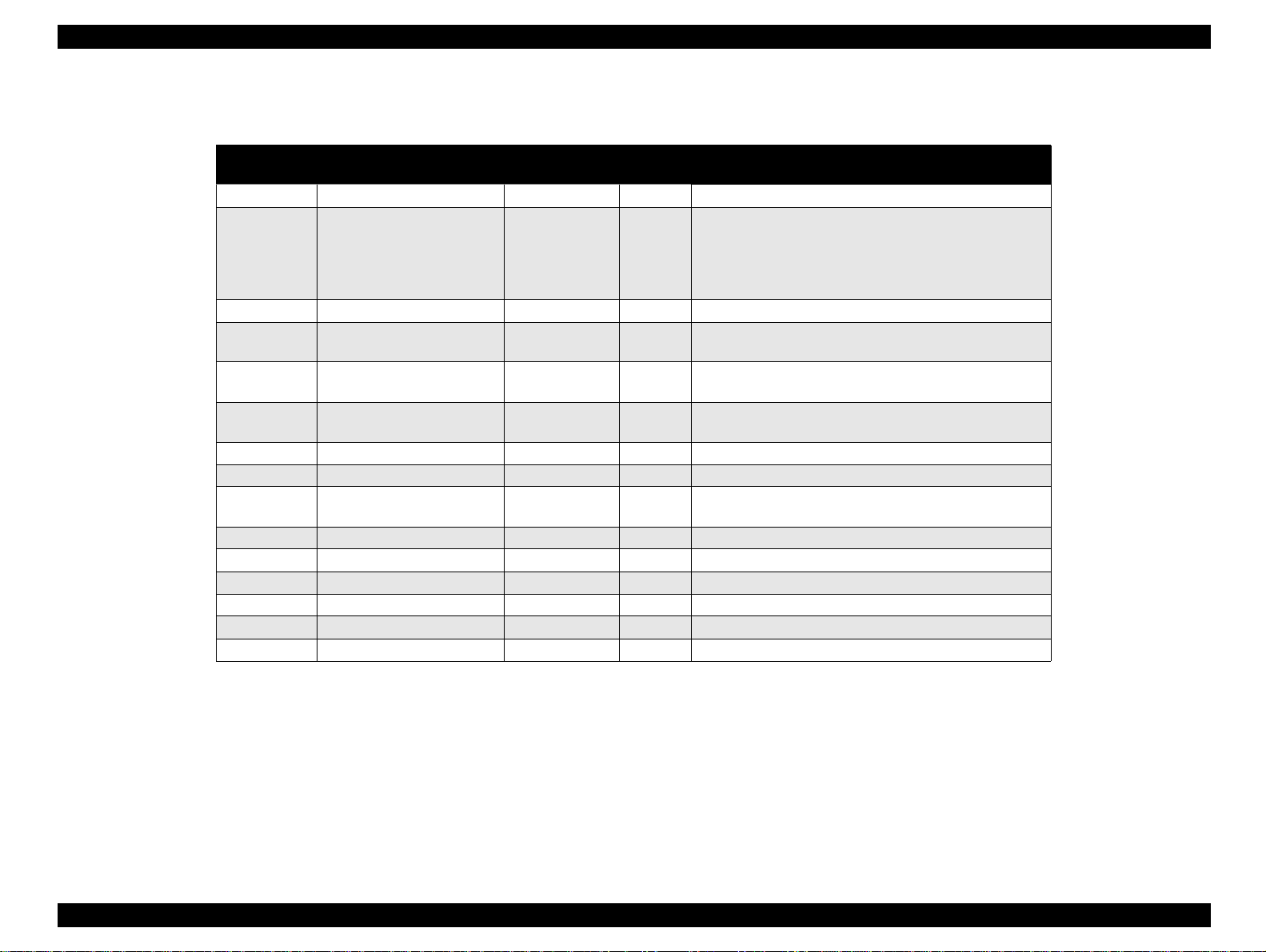
REVISION STATUS
Rev. Date Page(s) Contents
A 1998/07/15 All First Release
B 1998/09/30 Page 188
Pages 195 to 212
The exploded diagrams and part list for the Stylus Color 740 has been added.
Page 6

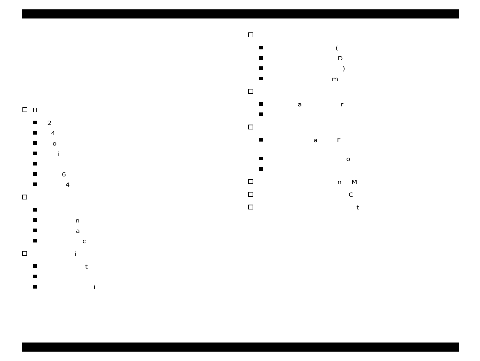
Product Description
Features ................................... ....... ...... ....... ...... ....... .............................. 9
Specifications ........................................................................................ 11
Printing Specification........................................................................ 11
Paper Specification .......................................................................... 15
Printing Area..................................................................................... 17
Ink Cartridge Specifications.............................................................. 20
Environmental Condition.................................................................. 22
Electric Specification ........................................................................ 23
Reliability.......................................................................................... 23
Safety Approvals .............................................................................. 23
Acoustic Noise.................................................................................. 24
CE Marking.............. ...... ...... ............................................................. 24
Input Data Buffer .............................................................................. 24
Interface................................................................................................. 25
Parallel Interface (Forward Channel) ............................................... 25
Parallel Interface (Reverse Channel) ............................................... 27
Serial Interface (for Stylus Color 640, 740) ...................................... 31
Control Panel......................................................................................... 32
Indicators (LEDs).............................................................................. 32
Panel Functions................................................................................ 33
Printer Condition and Panel Status.................................................. 34
Error Status ........................................................................................... 35
Ink Out.............................................................................................. 35
Paper Out......................................................................................... 35
Paper Jam........................................................................................ 35
No Ink-Cartridge............................................................................... 36
Maintenance Request ...................................................................... 36
Fatal Errors....................................................................................... 36
Printer Initialization ................................................................................ 37
Initialization Settings.............................................................................. 37
Main Components ................................................................................. 38
Printer Mechanism ........................................................................... 38
C206 Main-B Board (Stylus Color 440)............................................ 39
C256 Main Board (Stylus Color 640)................................................ 39
C257 Main Board (Stylus Color 740)................................................ 40
Power Supply Board
C206 PSB/PSE (Stylus Color 440, 640)
C257 PSB/PSE (Stylus Color 740)................................................... 40
C206 PNL Board (Stylus Color 440, 640)......................................... 41
C209 PNL Board (Stylus Color 740)................................................. 41
Operating Principles
Overview................................................................................................ 43
Printer Mechanism............................................................................ 44
Electrical Circuit Operating Principles.................................................... 56
C206 PSB/PSE and C257 PSB/PSE Power Supply Board (for Stylus Color
440, 640, 740) .................................................................................. 57
C206 Main-B, C255 Main (for Stylus Color 440) .............................. 60
C256 Main (for Stylus Color 640)..................................................... 62
C257 Main, (for Stylus Color 740).................................................... 64
Troubleshooting
Troubleshooting..................................................................................... 82
Unit Level Troubleshooting.................................................................... 85
Printer does not operate at power on............................................... 85
Error is detected ............................................................................... 86
Failure occurs during printing .............................................. ....... ...... 86
Printer does not feed paper correctly. .............................................. 87
Control panel operation is abnormal................................................. 87
Unit Repair of Power Supply Board....................................................... 88
Unit Repair of the Main Board ............................................................... 91
Repair of the Printer Mechanism........................................................... 96
Disassembly and Assembly
Overview.............................................................................................. 100
Precautions for Disassembling the Printer ..................................... 100
Tools............................................................................................... 101
Specification for Screws ................................................................. 102
Service Checks After Repair ............... ...... ....... ...... ....... ...... ....... .... 103
Page 7

Disassembly Procedures..................................................................... 104
Removing the Housing................................................................... 105
Removing the Board Assembly...................................................... 106
Removing the Operation Panel...................................................... 108
Disassembling the Printer Mechanism........................................... 109
Adjustment
Overview.............................................................................................. 130
Required Adjustments.................................................................... 130
Adjustment Tools Required............................................................ 131
Adjustment........................................................................................... 132
Parallelism Adjustment................................................................... 132
Adjustment by Adjustment Program........................................ ....... 134
Maintenance
Overview.............................................................................................. 154
Cleaning......................................................................................... 154
Service Maintenance........... ....... ....................................... ...... ....... 154
Lubrication...................................................................................... 155
Appendix
Connector Summary............................................................................ 161
Connector Summary (Stylus Color 440/640).................................. 162
Connector Summary for Stylus Color 740...................................... 166
EEPROM Address Map....................................................................... 169
EEPROM ADDRESS Map (Stylus Color 440/640)......................... 169
EEPROM Address Map (Stylus Color 740).................................... 174
Circuit Board Component Layouts....................................................... 178
Exploded Diagrams ............................................................................. 188
Part List ............................................................................................... 198
Part List for Stylus Color 440/640.................................................. 198
Part List for Stylus Color 740......................................................... 200
Circuit Diagrams.................................................................................. 202
Page 8

PRODUCT DESCRIPTION
Page 9
EPSON Stylus Color 440/640/740 Revision A
1.1 FEATURES
EPSON Stylus Color 440/640/740 are designed for PC users at home
and low price for hat high performance. Also, Stylus Color 440 printer
has the same high color print quality (720 X 720dpi) as Stylus ProXL,
and Stylus Color 640,740 have the same high color pri nt quality ( 1440 X
720) as Stylus Color 600 and Stylus Pro 5000. The major printer
features are;
High color print quality
720 (H) x 720 (V) dpi printing (for Stylus Color 440)
1440 (H) X 720 (V) dpi printing (for Stylus Color 640,740)
4 color printing (YMCBk)
Traditional and New Microwave
Black 64 nozzles, CMY 21 nozzles (for Stylus Color 440)
Black 64 nozzles, CMY 32/color nozzles (for Stylus Color 640)
Black 144 nozzles, CMY 48/color nozzles (for Stylus Color 740)
Built-in auto sheet feeder
Holds 100 cut-sheets (55g/m
2
)
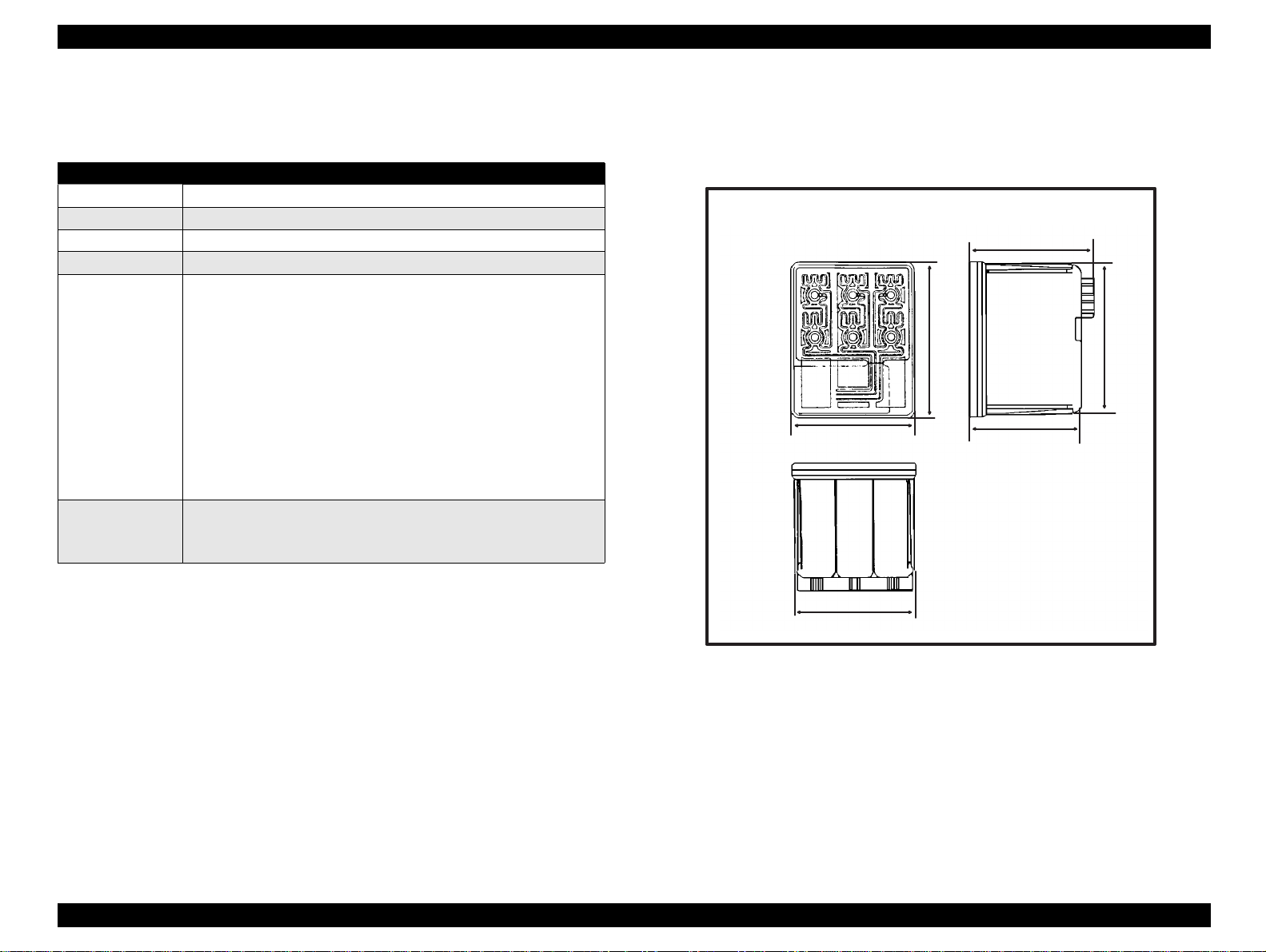
Compact size
429mm (W) x 231mm (D) x 155mm (H) (for Stylus Color 440)
429mm (W) x 231mm (D) x 157mm (H) (for Stylus Color 640)
429mm (W) x 261mm (D) x 157mm (H) (for Stylus Color 740)
Weight: 5.2Kg (for 3 models)
Acoustic noise
Approximately 45 dB (for Stylus Color 440)
Approximately 47 dB (for Stylus Color 640, 740)
Interface
Bi-directional parallel I/F IEEE-1284 level 1 device (for 3
models)
Serial I/F up to 1800 bps (only for Stylus Color 640)
USB
One unit combined black and CMY head
Windows exclusive (for Stylus Color 440, 640)
Standard, NLSP, 5 Scaleable fonts (only for Stylus Colo r 740)
Holds 10 envelopes
Holds 10 transparency films
Holds 65 special papers
High-speed print
200 cps (for Stylus Color 440, 740)
Normal 200 cps, Draft 400 cps (only for Stylus Color 640)
By using head drive frequency 14.4KHz, printing speed is twice
faster
than Stylus Color.
See Table 1-1 in the following page for the consumable list.
Chapter 1 Product Description 9
Page 10
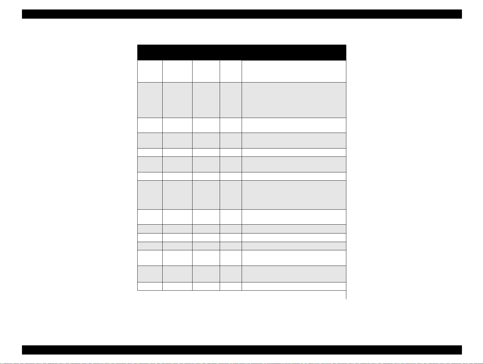
EPSON Stylus Color 440/640/740 Revision A
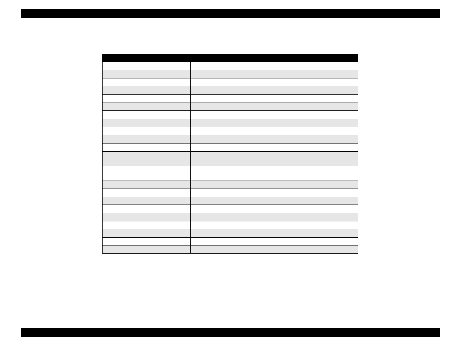
Table 1-1. Consumables Available for Stylus Color 440/640/740
Items Codes Remarks
Black Ink Cartridge S020189 Stylus Color 740
Black Ink Cartridge S020187 Stylus Color 440,640
CMY Ink Cartridge S020191 Stylus Color 440,640,740
CMY Ink Cartridge
EPSON 360 dpi Ink Jet Paper S041025 Size: A4 (200 sheets)
EPSON 360 dpi Ink Jet Paper S041059 Size: A4 (100 sheets)
EPSON 360 dpi Ink Jet Paper S041060 Size: Letter (100 sheets)
Photo Quality Ink Jet Paper S041026 Size: A4 (200 sheets)
Photo Quality Ink Jet Paper S041061 Size: A4 (100 sheets)
Photo Quality Ink Jet Paper S041062 Size: Letter
Photo Quality Ink Jet Paper S041067 Size: Legal
Photo Quality Glossy Paper (New
Release)
Photo Quality Glossy Paper (New
Release)
Photo Quality Glossy Film S041071 Size: A4
Photo Quality Glossy Film S041124 Size: Letter
Photo Quality Glossy Film S041107 Size: A6
Ink Jet Transparencies S041063 Size: A4
Ink Jet Transparencies S041064 Size: Letter
Photo Quality Ink Jet Card S041054 Size: A6
Photo Quality Ink Jet Card S041121 Size: 5 x 8 inches
Photo Quality Ink Jet Card S041122 Size: 10 x 8 inches
Photo Quality Self Adhesive Sheet S041106 Size: A4
S041126 Size: A4
S041124 Size: Letter
Chapter 1 Product Description 10
Page 11
EPSON Stylus Color 440/640/740 Revision A
1.2 Specifications
This section describes each specificat ion for Stylus Col or 440, 640 , and
740.
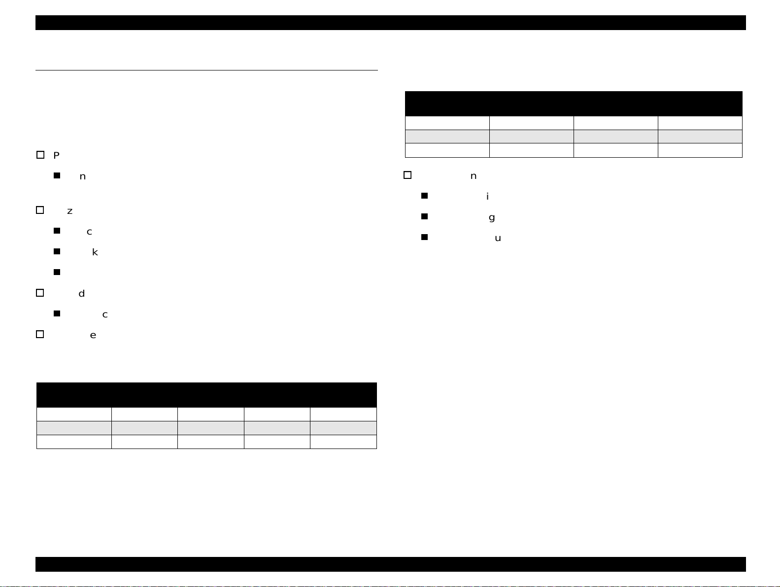
1.2.1 Printing Specification
Print method
On demand ink jet (MACH type. One unit combined with black
and CMY head)
Nozzle configuration
Black 64 nozzles, CMY 21 nozzles (for Stylus Color 440)
Black 64 nozzles, CMY 32/color nozzles (for Stylus Color 640)
Black 144 nozzles, CMY 48/color nozzles (for Stylus Color 740)
Print direction
Bi-direction with logic seeking
Print speed and Printable columns, character pi tch and print quality
Refer to Table 1-2 and Table 1-3.
Horizontal
Resolution
180 dpi 8.26 1488 20 IPS
360 dpi 8.26 2976 20 IPS
720 dpi 8.26 5952 20 IPS
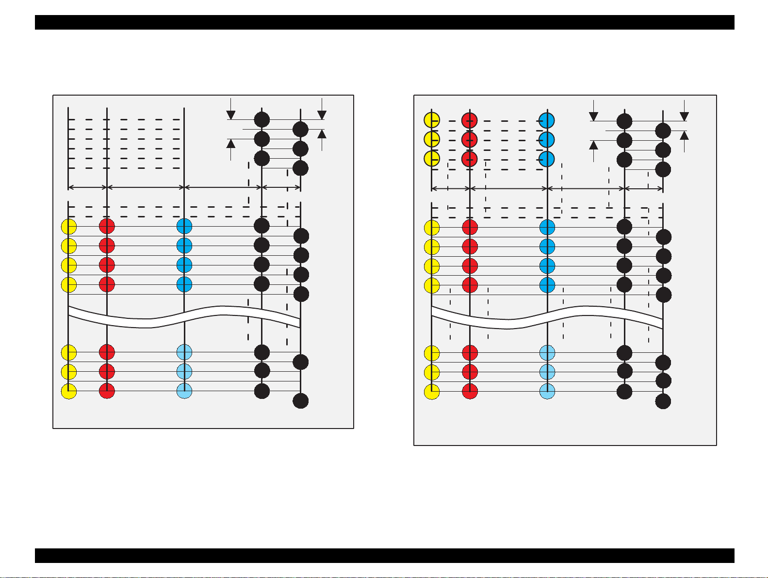
Nozzle Configuration:
Refer to Figure 1-1 for Stylus Color 440.
Refer to Figure 1-2 for Stylus Color 640.
Refer to Figure 1-3 for Stylus Color 740.
Table 1-3. Graphic Mode Speed
Printable Area Available dot CR Speed
Table 1-2. Character Mode Speed
Model Name
Stylus Color 440 10 80 200 CPS --Stylus Color 640 10 80 200 CPS 400 CPS
Stylus Color 740 10 80 200 CPS ---
Character
Pitch
Printable
Column
LQ Speed Draft Speed
Chapter 1 Product Description 11
Page 12
EPSON Stylus Color 440/640/740 Revision A
Y1
Y2
Y3
Y4
Y19
Y20
Y21
M 1
M 2
M 3
M 4
M 19
M 20
M 21
#1
90DPI
#3
#5
10.16 mm2.2578 mm
7.9022 mm
C1
C2
C3
C4
C19
C20
C21
#23
#25
#27
#29
#59
#61
#63
#2
#4
#6
2.2578 mm
#24
#26
#60
#62
#64
180DPI
Y1
Y2
Y3
2.2578 mm
Y12
Y13
Y14
Y15
Y30
Y31
Y32
M1
M2
M3
10.16 mm
M12
M13
M14
M15
M30
M31
M32
C1
C2
C3
7.9022 mm
C12
C13
C14
C15
C30
C31
C32
90DPI
#1
#3
#5
#23
#25
#27
#29
#59
#61
#63
#2
#4
#6
2.2578 mm
#24
#26
#60
#62
#64
180DPI
(Y)
(M)
(C)
(B2)
(B1)
(Y)
(M)
(C)
(B2)
(B1)
Figure 1-1. Nozzle Configuration for Stylus Color 440
Figure 1-2. Nozzle Configuration for Stylus Color 640
Chapter 1 Product Description 12
Page 13
EPSON Stylus Color 440/640/740 Revision A
Feeding method
32/360"
#1
#2
#3
#4
#5
#6
#7
#8
#9
#10
#11
112/360"
#1
#2
#3
#4
#5
#6
#7
#8
#9
#10
#11
32/360"
#1
#2
#3
#4
#5
#6
#7
#8
#9
#10
#11
112/360"
#1
#4
#7
#10
#13
#16
#19
#22
#25
#28
#31
32/360"
#2
#5
#8
#11
#14
#17
#20
#23
#26
#29
#32
#3
#6
#9
#12
#15
#18
#21
#23
#26
#29
#32
Friction feed with ASF
Line spacing
1/6 inches or programmable at 1/360 inches (only for Stylus
Color 440)
1/6, 1/8 inches or programmable at 1/360 inches (for Stylus
Color 640,740)
Paper path
Cut-sheet ASF (Top entry)
Feeding speed
<Stylus Color 440, 640>
190 ms (1/3 inch)
2.0 inches/seconds (continuous)
<Stylus Color 740>
110 ms (10.16 mm)
114.3 mm/second (Continuous)
Ink supply
Exclusive ink cartridge (Black and CMY)
(B1)
#139
#142
(B2)
#140
#141
#143
#144
(B3)
#47
#48
#47
#48
(M)(Y)
#47
#48
(C)
Figure 1-3. Nozzle Configuration for Stylus Color 740
Chapter 1 Product Description 13
Page 14
EPSON Stylus Color 440/640/740 Revision A
Paper holding capacity of Hopper
Size: Index card ∼Legal
Thickness: Less than 8mm
Paper capacity: 100 Cut sheets
10 Envelopes
65 Coated papers (360 dpi)
65 Coated papers (720 dpi)
20 Glossy papers, Photo Paper
10 Transparent sheets
30 Index cards
1 Panoramic Photo Paper, Iron-On Cool Peel
Transfer Paper, and Photo Sticks,
Glossy Film, Self Adhesive
Character tables: 2 international character sets (Not Opened)
<Stylus Color 440, 640>
PC437 (US, Standard Europe)
PC850 (Multilingual)
Typeface
Bit map LQ font: EPSON Courier 10CPI
<Stylus Color 740>
Standard version:11 character tables
Italic table, PC437 (US Standard, Europe), PC 850
(Multilingual), PC860 (Portuguese), PC861 (Icelandic), PC863
(Canadian-French), PC865 (Nordic), Abicomp, BRASCII,
Roman 8, ISO Latin 1
NLSP Version: 30 character tables
NOTE:*1 is not opened. These character tables can not be selected in
NOTE:The above typeface has 4 variations individually as follows;
Bulgaria, ic), PC774, Estonia, ISO 8859-2, PC866-LAT, PC866 UKR,
*1
PC AR864, PC APTEC, PC708, PC720, Hebrew7
PC862
*1
Hebrew8*1,
the default setting mode.
Typeface
Bit map LQ font:
EPSON Roman 10 CPI, 12 CPI, 15 CPI, Proportional
EPSON Sans Serif 10 CPI, 12 CPI, 15 CPI, Proportional
EPSON Courier 10 CPI, 12 CPI, 15 CPI
EPSON Prestige 10 CPI, 12 CPI, 15 CPI
EPSON Script 10 CPI, 12 CPI, 15 CPI
Scaleable font:
EPSON Roman 10.5pt., 8pt. to 32 pt. (every 2 pt. unit)
EPSON Sans Serif 10.5pt., 8pt. to 32 pt. (every 2 pt. unit)
EPSON Roman T 10.5pt., 8pt. to 32 pt. (every 2 pt. unit)
EPSON Sans Serif H 10.5pt., 8pt. to 32 pt. (every 2 pt. unit)
EPSON Roman, EOSON Roman bold
EPSON Roman Italic, EPSON Roman bold Italic
Control code
<Stylus Color 440, 640>
ESC/P Raster
EPSON Remote command
<Stylus Color 740>
ESC/P2 and ESC/P Raster
EPSON Remote command
Italic table, PC437, PC437 Greek, PC 850, PC852, PC853, PC855,
PC857, PC860, PC861, PC865, PC866, ISO8859-7, ISO Latin 1T,
Chapter 1 Product Description 14
Page 15

EPSON Stylus Color 440/640/740 Revision A
1.2.2 Paper Specification
This section describes the printa ble area and types of paper that can be
used in this printer.
1.2.2.1 Cut Sheet
[Size]
A4: [Width 210mm (8.3”) x Length 297mm (11.7”)]
Letter: [Width 216mm (8.5”) x Length 279mm (11.0”)]
B5: [Width 182mm (7.2”) x Length 257mm (10.1”)]
Legal: [Width 216mm (8.5”) x Length 356mm (14.0”)]
Statement: [Width]139.7mm (5.5”) x Length 215.9mm (8.5”)]
Exclusive: [Width 190.5mm (7.5”) x Length 254mm (10”)]
[Thickness]
0.08mm (0.003”) - 0.11mm (0.004”)
[Weight]
2
64g/m
(17Ib.) - 90g/m2 (24Ib.)
1.2.2.2 Transpa rency, Glossy Paper
[Size]
A4: [Width 210mm (8.3”) x Length 297mm (11.7”)]
Letter: [Width 216mm (8.5”) x Length 279mm (11.0”)]
[Thickness]
0.075mm(0.003”) - 0.085mm(0.0033”)
NOTE:Transparency printing is only available at normal temperature.
1.2.2.3 Envelope
[Size]
No.10 Width 241mm (9 1/2”) x Length 104.8mm (4 1/8”)
DL Width 220mm (8.7”) x Length 110mm (4.3”)
C6 Width 162mm (6.4”) x Length 114mm (4.5”)
[Thickness]
0.16mm (0.006”) - 0.52mm (0.02”)
[Quality]
Exclusive paper, Bond paper, PPC
[Weight]
2
45g/m
[Quality]
Bond paper, Plain paper, Air mail
(12Ib.) - 75g/m2 (20Ib.)
NOTE 1 Envelope printing is only available at normal temperature.
NOTE 2 Keep the longer side of the envelope horizontally at setting.
Chapter 1 Product Description 15
Page 16

EPSON Stylus Color 440/640/740 Revision A
1.2.2.4 Index Card
[Size]
A6 Index card: Width 105mm (4.1”) x Length 148mm (5.8”)
A5 Index card: Width 148mm (5.8”) x Length 210mm (8.3”)
5x8” Index card: Width 127mm (5.0” x Length 203mm (8.0”)
10x8” Index card: Width 127mm (5.0”) x Length 203mm (8.0”)
[Thickness]
: Less than 0.23mm (0.0091”)
Chapter 1 Product Description 16
Page 17
EPSON Stylus Color 440/640/740 Revision A
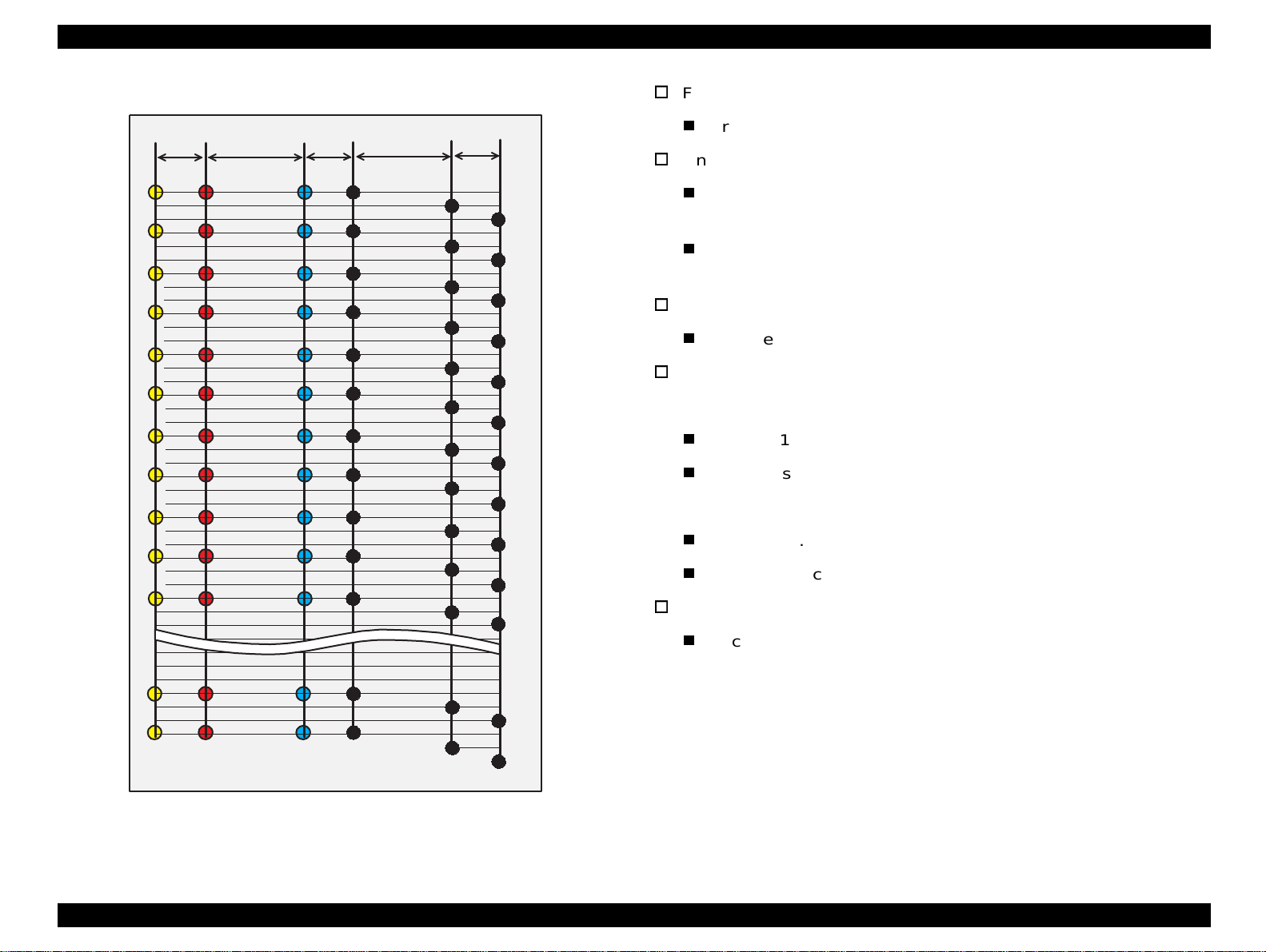
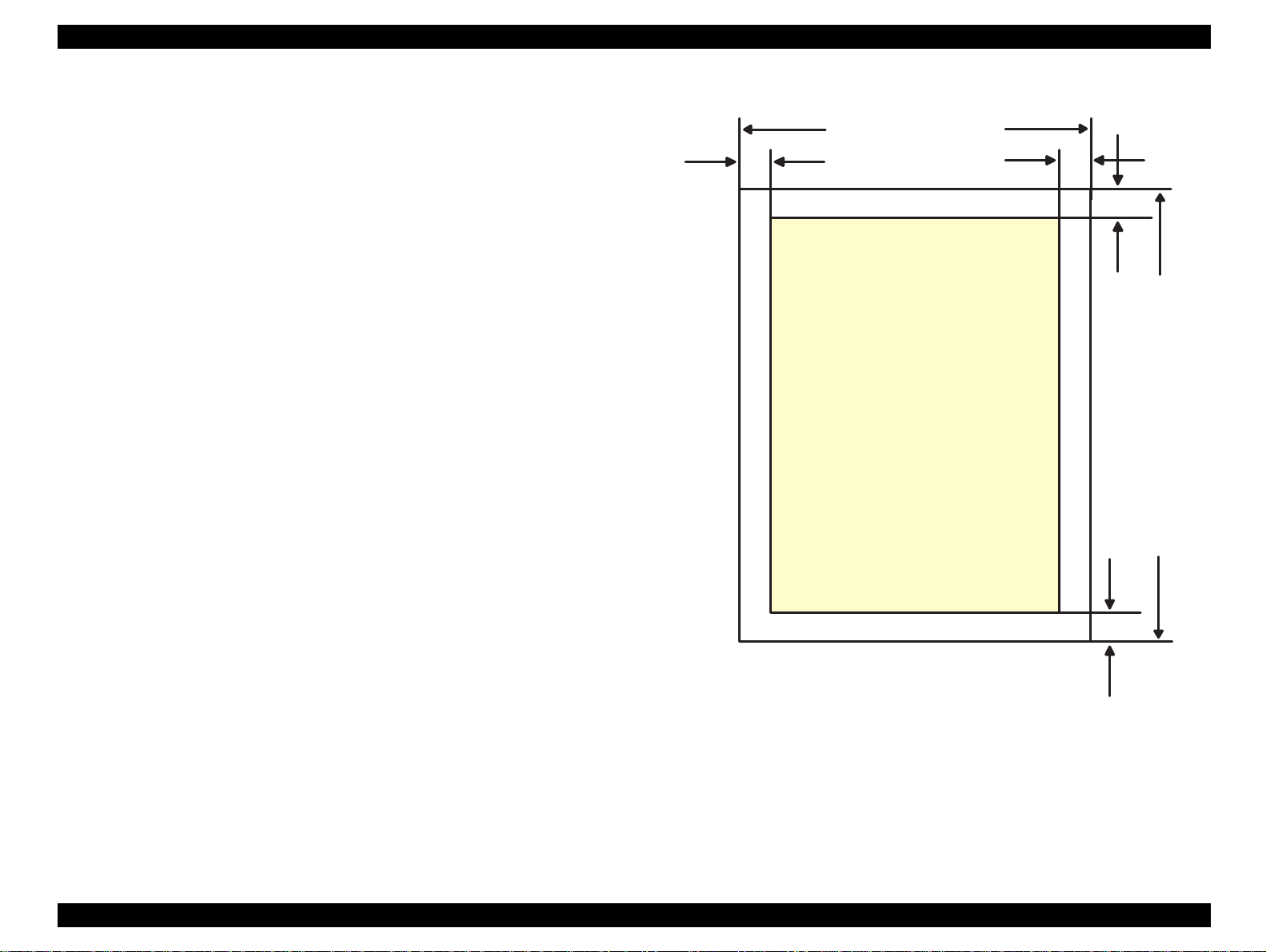
1.2.3 Printing Area
[Cut Sheet]
See Figure 1-4 in the right column and the tables in the following page
for the printable areas for Raster Graphics mode and Character mode.
NOTE:Character mode is only suitable for Stylus Color 740.
LM
PW
Printable
Area
RM
TM
PL
BM
Figure 1-4. Printable Area for Cut sheet
Chapter 1 Product Description 17
Page 18
EPSON Stylus Color 440/640/740 Revision A
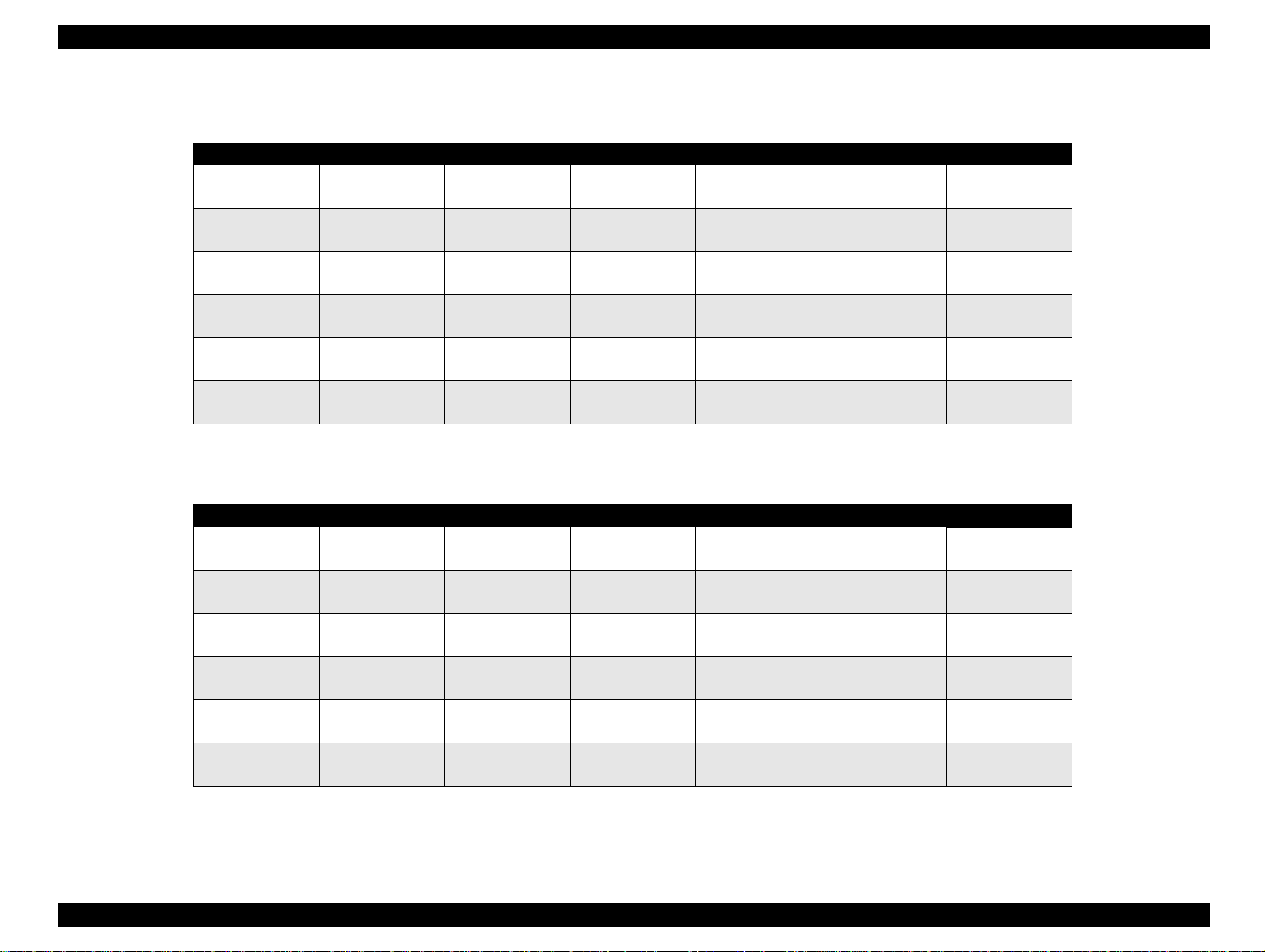
Table 1-4. Raster Graphics Mode (for 3 models)
Paper Size PW PL LM RM TM BM/min.
A4 210 mm (8.3”) 297 mm (11.7”) 3 mm (0.12”) 3 mm (0.12”) 3 mm (0.12”)
Letter 216 mm (8.5”) 279 mm (11.0”) 3 mm (0.12”) 9 mm (0.35”) 3 mm (0.12”)
B5 182 mm (7.2”) 257 mm (10.1”) 3 mm (0.12”) 3 mm (0.12”) 3 mm (0.12”)
Legal 216 mm (8.5”) 356 mm (14.0”) 3 mm (0.12”) 9 mm (0.35”) 3 mm (0.12”)
Statement 139.7 mm (5.5”) 215.9 mm (8.5”) 3 mm (0.12”) 3 mm (0.12”) 3 mm (0.12”)
Exclusive 190.5 mm (7.5”) 254 mm (10”) 3 mm (0.12”) 3 mm (0.12”) 3 mm (0.12”)
14 mm(0.54”)
3 mm (0.12”)
14 mm (0.54”)
3 mm (0.12”)
14 mm (0.54”)
3 mm (0.12”)
14 mm (0.54”)
3 mm (0.12”)
14 mm (0.54”)
3 mm (0.12”)
14 mm (0.54”)
3 mm (0.12”)
Table 1-5. Character Mode (only for Stylus Color 740)
Paper Size PW PL LM RM TM BM/min.
A4 210mm (8.3”) 297mm (11.7”) 3mm (0.12”) 3mm (0.12”) 3mm (0.12”)
Letter 216mm (8.5”) 279mm (11.0”) 3mm (0.12”) 9mm (0.35”) 3mm (0.12”)
B5 182mm (7.2”) 257mm (10.1”) 3mm (0.12”) 3mm (0.12”) 3mm (0.12”)
Legal 216mm (8.5”) 356mm (14.0”) 3mm (0.12”) 9mm (0.35”) 3mm (0.12”)
Statement 139.7mm (5.5”) 215.9mm (8.5”) 3mm (0.12”) 3mm (0.12”) 3mm (0.12”)
Exclusive 190.5mm (7.5”) 254mm (10”) 3mm (0.12”) 3mm (0 .12”) 3mm (0.12”)
14mm (0.54”)
3 mm (0.12”)
14mm (0.54”)
3 mm (0.12”)
14mm (0.54”)
3 mm (0.12”)
14mm (0.54”)
3 mm (0.12”)
14mm (0.54”)
3 mm (0.12”)
14mm (0.54”)
3 mm (0.12”)
Chapter 1 Product Description 18
Page 19
EPSON Stylus Color 440/640/740 Revision A
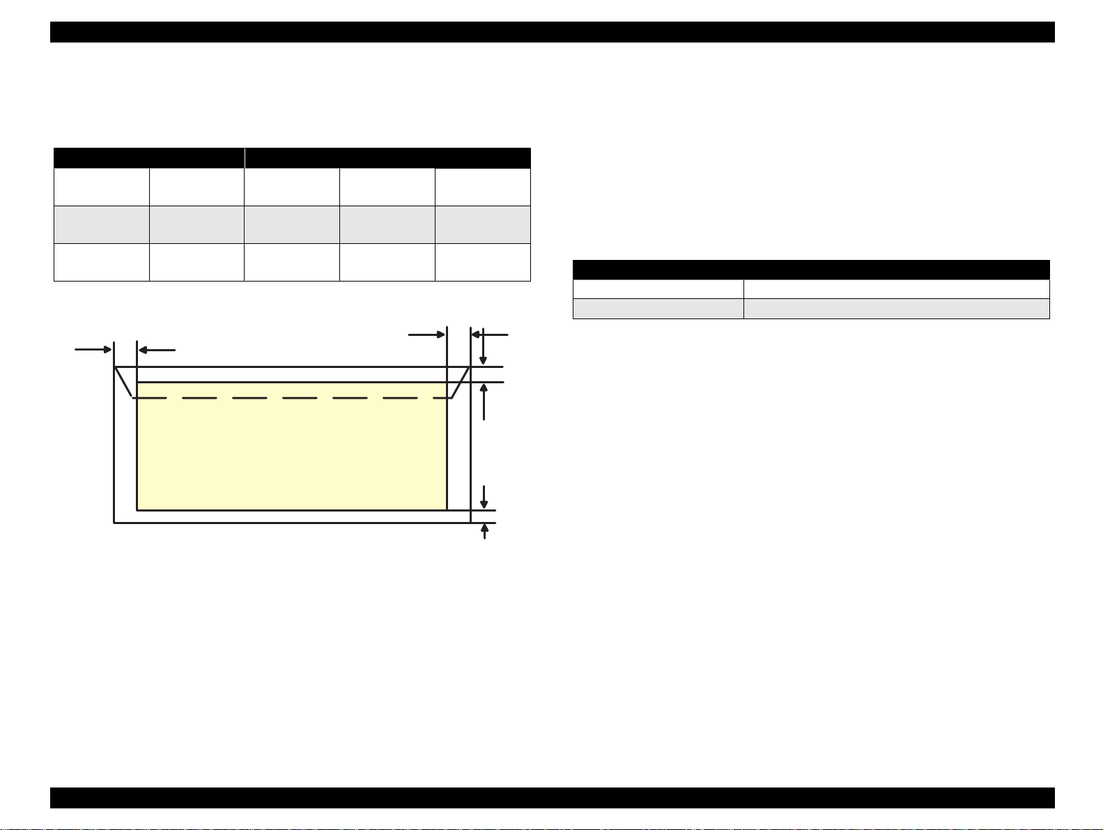
[Envelope]
Table 1-6 and Figure 1-5 show the printable area for envelopes.
Table 1-6. Envelopes Margin
Paper Size LM RM TM BM/min.
#10 28 mm (1.10”) 3 mm (0.12”) 3 mm (0.12”)
DL 7 mm (0.28”) 3 mm (0.12”) 3 mm (0.12”)
C6 3 mm (0.12”) 3 mm (0.12”) 3 mm (0.12”)
LM
14 mm (0.54”)
3 mm (0.12”)
14 mm (0.54”)
3 mm (0.12”)
14 mm (0.54”)
3 mm (0.12”)
RM
Printable
Area
TM
BM
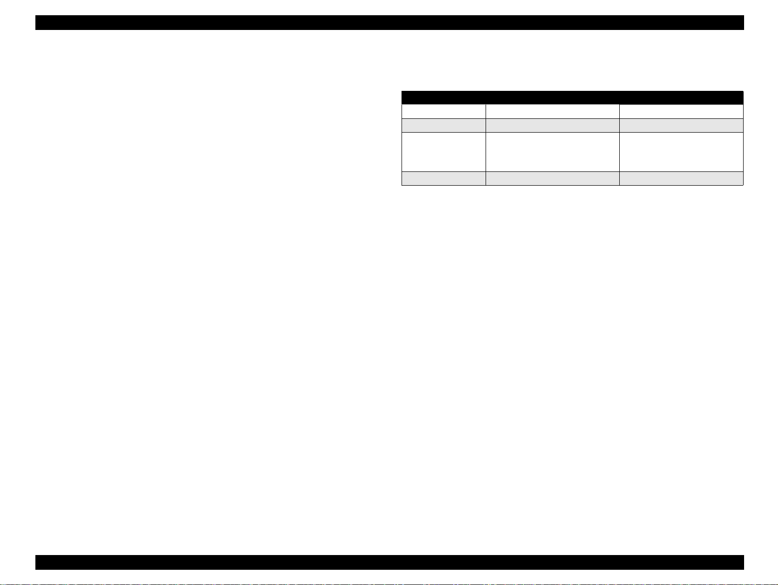
1.2.3.1 Adjust Lever Setting
The adjustment lever located on the right side (dark blue) under the
printer cover needs to be set to the proper position accord ing to the
paper you print. (Refer to the Tabl e 1-7.) Al so, if t here is any dirt caus ed
by friction on the way or wrinkled paper, this can be prevented by
changing the lever position to rear position (marked with “+”) in spite of
paper types.
Table 1-7. Adjust Lever Setting
Lever Position Clearance between head and platen
Plus Position 1.04 mm
Zero Position 1.74 mm (+0.7 mm)
NOTE:Return the adjust lever to the zero position, which is normal
position, after you finish printing on all media. Leaving the lever
in the plus position may cause the printed image to have gaps
on other media.
Figure 1-5. Printable Area for Envelopes
Chapter 1 Product Description 19
Page 20
EPSON Stylus Color 440/640/740 Revision A
18.3
38.5
51.2
19.8
52.7
27.8
52.7
38.5
51.2
26.3
18.3
38.5
51.2
19.8
52.7
for Stylus C olor 440, 640
for Stylus C olor 740
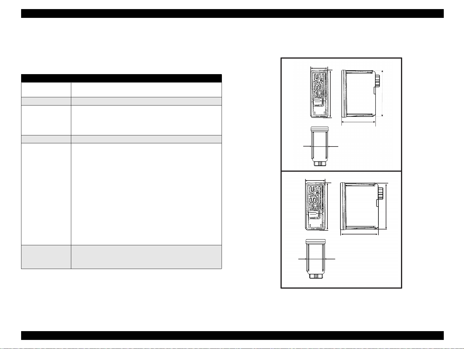
1.2.4 Ink Cartridge Specifications
[Black Ink Cartridge]
Table 1-8. Black Cartridge Specifications
Items Specifications
Type Exclusive Cartridge for Stylus Color 440, 640
Exclusive Cartridge only for Stylus Color 740
Color Black
Print Capa city <Stylus Color 440,640>
Validity 2 years (sealed in package) / 6 months (out of package)
Environmental
conditions
Weight Total Ink Cartridge: 30 g
540 pages / A4 (ISO/IEC 10561 Letter Pattern at 360 dpi)
<Stylus Color 740>
900 pages / A4 (ISO/IEC 10561 Letter Pattern at 360 dpi)
• Temperature
- Storage: -20°C~40°C (within a month at 40 °C)
- Packing storage: -30°C~40°C (within a month at 40 °C)
- Transit: -30°C~60°C (within 120 hours at 60°C and within
a month at 40°C)
• Humidity
5% to 85% (without condensation)
Note:
Ink freezes below -3°C, but it returns to normal after 3 hours at
room temperature. (25 °C)
• Dimension
<Stylus Color 440,640>
19.8 mm (W) X 52.7 mm (D) X 38.5 mm (H)
<Stylus Color 740>
27.8 mm (W) X 52.7 mm (D) X 38.5 mm (H)
Total Ink: 16.4 +/-0.5 g
Consumable Ink weight: more than 12.1 g
Figure 1-6. Black Ink Cartridge Appearance
Chapter 1 Product Description 20
Page 21
EPSON Stylus Color 440/640/740 Revision A
[Color Ink Cartridge]
Table 1-9. Color I/C Specifications
Items Specifications
Type Exclusive Cartridge for Stylus Color 440, 640, 740
Color CMY
Print Capacity 300 pages / A4 (360 dpi, 5% duty each colors)
Validity 2 years (sealed in package) / 6 months (out of package)
Environmental
conditions
• Temperature
- Storage: -20°C~40°C (within a month at 40 °C)
- Packing storage: -30°C~40°C (within a month at 40 °C)
- Transit: -30°C~60°C (within 120 hours at 60°C and within a
month at 40°C)
•Humidity
5% to 85% (without condensation)
Note:
Ink freezes below -3°C, but it returns to normal after 3 hours at
room temperature. (25 °C)
• Dimension
42.9 mm (W) X 52.7 mm (D) X 38.5 mm (H)
Weight Total Ink Cartridge: 67 g
Total Ink: 12.8 +/-0.5 g/colors
Consumable Ink weight: more than 9.6 g/colors
52.7
42.9
43.2
51.2
38.5
41.4
Figure 1-7. Color Ink Cartridge
Chapter 1 Product Description 21
Page 22
EPSON Stylus Color 440/640/740 Revision A
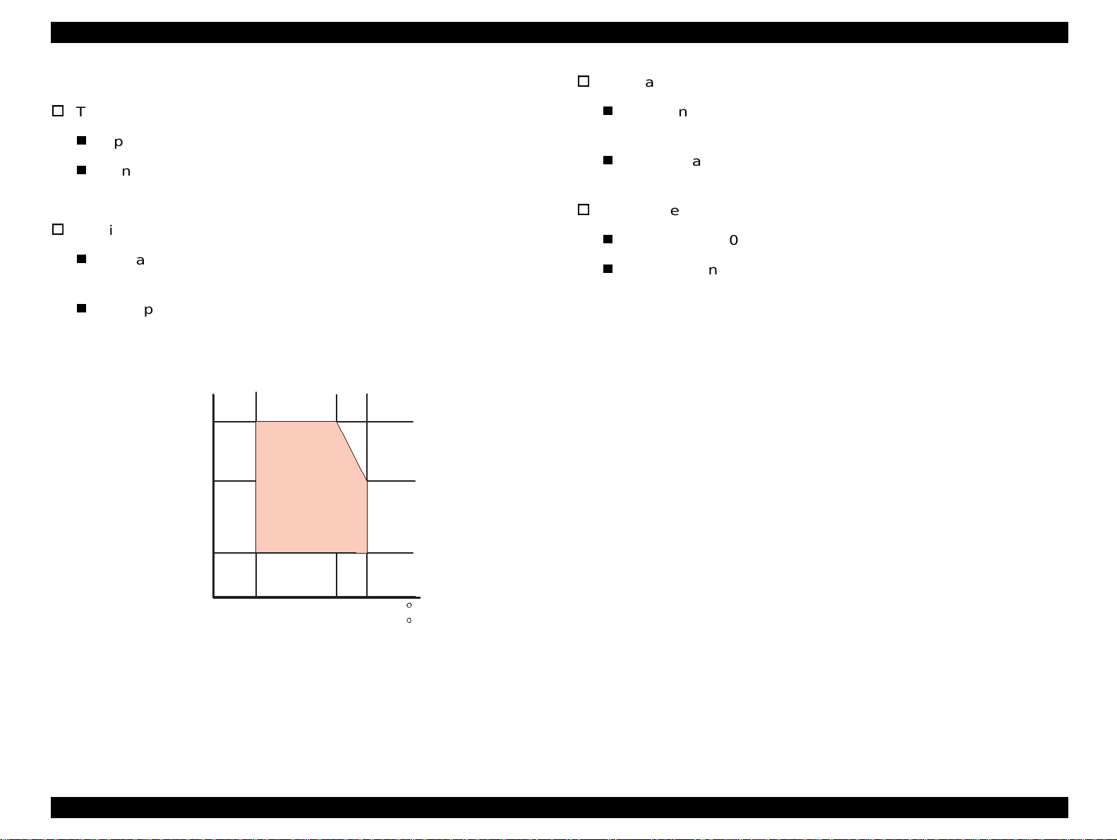
1.2.5 Environmental Condition
Temperature
Operating :10 to 35 °C (Refer to Figure 1-8 for condition)
Non-operating:-20 to 60 °C (with shipment container)
NOTE: 1 month at 40 °C and 120 hours at 60 °C
Humidity
Operating: 20% ~ 80% RH
(without condensation Refer to Figure 1-8 for condition)
Resistance to shock
Operating: 1G, within 1 ms
Non-operating:2G, within 2 ms
Resistance to vibration
Operating: 0.15G (Operating)
Non-operating:0.50G (Non-Operating)
X,Y,Z directions
X,Y,Z directions (with shipment container)
Non-operating: 5% ~ 85% RH
(without condensation and with shipment container)
Humidity
(% RH)
80%
55%
20%
Figure 1-8. Temperature / Humidity of Range
Guaranteed
Area
10 27 35
50
80
95
NOTE 1:During non-operating, make sure that the head is capped.
NOTE 2:During the transport, make sure that the head is capped and
ink cartridge is installed to the printer.
NOTE 3: If the head is not capped at the powe r-off sta te, tur n the power
on with installed ink cartridge and turn off the power after
confirming that Power on operati on is completed and the head
is capped.
NOTE 4: Ink will be frozen less than -3°C environment, however it
will be usable after placing it more than 3 hours at 25°C.
( C )
( F )
Chapter 1 Product Description 22
Page 23

EPSON Stylus Color 440/640/740 Revision A
1.2.6 Electric Specification
[120V version]
[Rated voltage] AC120V
[Input voltage range] AC99∼132V
[Rated frequency range] 50∼60Hz
[Input frequency range] 49.5∼60.5 Hz
[Rated current 0.4A (Max. 0.5A)
[Power consumption] Approx.15W (ISO/IEC 10561 Letter pattern)
Energy Star compliant
[Insulation Resistance] 10M ohms min.
(between AC line and chassis, DC 500 V)
[Dielectric strength] AC1000 V rms. 1 minute or AC1200 Vrms.
1 second (between AC line and chassis)
[220∼240V version]
[Rated voltage] AC220V∼240V
[Input voltage range] AC198∼264V
[Rated frequency range] 50∼60Hz
[Input frequency range] 49.5∼60.5 Hz
[Rated current] 0.2 A (Max. 0.3A)
[Power consumption] Approx.15W (ISO/IEC 10561 Letter pattern)
Energy Star compliant
[Insulation Resistance] 10M ohms min.
(between AC line and chassis, DC500V)
[Dielectric strength] AC1500 V rms.
1 minute (between AC line and chassis)
1.2.7 Reliability
[Total print volume]
Stylus Color 440: 10,000 pages (A4, Letter)
Stylus Color 640: 25,000 pages (A4, Letter)
Stylus Color 740: 75,000 pages (A4, Letter)
[Print head life]
Stylus Color 440: 2000 million dots/nozzle
Stylus Color 640: 2000 million dots/nozzle
Stylus Color 740: 4000 million dots/nozzle
1.2.8 Safety Approvals
[120V version]
Safety standard UL1950 with D3
CSA22.2 No.950 with D3
EMI FCC part 15 subpart B class B
CSA C108.8 class B
[220∼240V]
Safety standard EN 60950 (VDE,NEMKO)
EMI EN55022 (CISPR Pub.22) class B
AS/NZS 3548 class B
Chapter 1 Product Description 23
Page 24

EPSON Stylus Color 440/640/740 Revision A
1.2.9 Acoustic Noise
Stylus Color 440: Approximately 45 dB
Stylus Color 640,740: Approximately 47 dB
1.2.10 CE Marking
[220∼240 V version]
Low Voltage Directive 73/23/EEC:EN60950
EMC Directive 89/336/EEC :EN55022 Class B
:EN61000-3-2
:EN61000-3-3
:EN50082-1
:IEC801-2
:IEC801-3
:IEC801-4
1.2.11 Input Data Buffer
10 K byte (for Stylus Color 440)
32 K byte (for Stylus Color 640)
64 K byte (for Stylus Color 740)
Chapter 1 Product Description 24
Page 25

EPSON Stylus Color 440/640/740 Revision A
1.3 Interface
This printer provides parallel i nterface as standard.
1.3.1 Parallel Interface (Forward Channel)
[Transmission mode]
[Synchronization]
[Handshaking]
[Signal level]
[Adaptable connector]
BUSY signal is set high before setting either/ERROR low or PE high
and held high until all these signals retur n to their inactive state.
BUSY signal is at high level in the following cases.
During data entry (see Data transmission timing)
When input data buffer is full
During -INIT signal is at low level or during hardware
initialization
8 bit parallel, IEEE-1284 compatibility mode
By /STOPBE pulse
BY BUSY and /ACKLG signal
TTL compatible level
57-30360 (amphenol) or equivalent
See Table 1-10 in the following page which shows the signal and
connector pin assignments f or paralle l interface (forward channel *1) . In
case of these signals, twist pair line is used and returning side is
connected to signal GND.
*1: Forward channel is the mode when the ordi nary data such as an order
to print is sent from the PC to the printer.
During printer error (See /ERROR signal)
/ERROR signal is at low level when the printer is in one of the fol lowing
states.
Printer hardware error (fatal error)
Paper-out error
Paper-jam error
Ink-out error
PE signal is at high level during paper-out error.
Chapter 1 Product Description 25
Page 26
EPSON Stylus Color 440/640/740 Revision A
Table 1-10. Parallel I/F Forward Channel
Pin No.
1 /STROBE 19 I
2-9 DATA0-7 20-27 I
10 /ACKNLG 28 O
11 BUSY 29 O
12 PE 28 O A high signal indicates paper-out error.
13 SLCT 28 O
14 /AFXT 30 I Not used.
31 /INIT 30 I
32 /ERROR 29 O
36 /SLIN 30 I Not used.
18 Logic H ---- O Pulled up to +5V via 3.9K ohm resistor.
35 +5V ---- O Pulled up to +5V via 3.9K ohm resistor.
17
16,33,
19-30
15,34 NC ---- --- Not connected.
Signal
Name
Chassis
GND
GND ---- --- Signal GND.
Note) In and Out refer to the direction of signal flow from the printer’s point of view.
Return
GND Pin
---- --- Chassis GND.
In/Out Functional Description
The strobe pulse. Read-in of data is
performed at the falling edge of this
pulse.
The DATA0 through DATA7 signals
represent data bits 0 to 7, respectively.
Each signal is at high level when data is
logical 1 and low level when data is
logical 0.
This signal is a negative pulse indicating
that the printer can again accept data.
A high signal indicates that the printer
cannot receive data.
Always at high level when the printer is
powered on.
The falling edge of a negative pulse or a
low signal on this line causes the printer
to initialize. Minimum 50 us pulse is
necessary.
A low signal indicates printer error
condition.
Chapter 1 Product Description 26
Page 27
EPSON Stylus Color 440/640/740 Revision A
1.3.2 Parallel Interface (Reverse Channel)
[Transmission mode]
[Synchronization]
[Handshaking]
[Data trans. timing]
[Signal level]
[Adaptable connector]
[Extensibility request]
00H: Request Nibble Mode Reverse Channel Transfer.
04H: Request device ID; Return Data using Nibble Mode Rev
Channel Transfer.
IEEE-1284 nibble mode
Refer to the IEEE-1284 specification
Refer to the IEEE-1284 specification
Refer to the IEEE-1284 specification
IEEE-1284 level 1 device
TTL compatible level
57-30360 (amphenol) or equivalent
The printer responds affirmatively when
the extensibility request values are 00H or
04H, that mean;
NOTE:The printer sends following device ID string when it is requested.
Table 1-11. Details of Device ID
00H 3CH Contents
MGF EPSON; Production Maker
CMD ESCPL2,BDC; Command system
Stylus[SP]Color[SP] 440;
MDL
CLS PRINTER; Class
NOTE:
NOTE:
[00H] denotes a hexadecimal value of zero. MDL value depends on the
EEPROM setting.
MDL value depends on the EEPROM setting. Model name can be changed by
changing a certain address in the EEPROM.
Stylus[SP]Color[SP] 640;
Stylus[SP]Color[SP] 740;
Model name
Table 1-12 shows pin assignment for reverse channel (*3). In these
case of signals, twist pair lin e is used and returni ng side is connect ed to
Signal GND.
*3: Reverse channel is the mode that any data is transferred from th e
printer to the PC.
Chapter 1 Product Description 27
Page 28
EPSON Stylus Color 440/640/740 Revision A
Table 1-12. Parallel I/F Reverse Channel
Pin No. Signal Name
1 HostClk 19 I Host clock signal.
2-9 Data0-7 20-27 I
10 PrtClk 28 O Printer clock signal.
11 PtrBusy, Data Bit-3,7 29 O
12 AckData Req, DataBit-2,6 28 O
13 Xflag, DataBit-1,5 28 O
14 HostBusy 30 I Host busy signal.
31 /INIT 30 I Not used.
32 /DataAvail, DataBit-0,4 29 O
36 1284-Active 30 I 1284 Active Signal
18 Logic-H ---- O Pulled up to +5V via 3.9K ohm resister.
35 +5V ---- O Pulled up to +5V via 3.3K ohm resister.
17 Chassis GND ---- --- Chassis GND.
16,33, 9-30 GND ---- --- Signal GND.
15,34 NC ---- --- Not connected.
Note) In/Out refers to the direction of signal flow from the printer’s point of view.
Return GND
Pin
In/Out Functional Description
The DATA0 through DATA7 signals represent data
bits 0 to7, respectively. Each signal is at high level
when data is logical 1 and low level when data is
logical 0. These signals are used to transfer the 1284
extensibility request values to the printer.
Printer busy signal and reverse channel transfer data
bit 3 or 7.
Acknowledge data reque st sign al and rev erse ch annel
transfer data bit 2 or 6.
X-flag signal and reverse cha nn el transf er data bit 1 or
5.
Data available signal and reverse channel transfer
data bit 0 or 4.
Chapter 1 Product Description 28
Page 29
EPSON Stylus Color 440/640/740 Revision A
The following are the points to note when using the parallel Interface.
NOTE 1:“Return GND pin” in the table means twist pair return and is
used for all control signals except for Logi c H,+5V, Chassis,
GND and NC. In this twist pair return, returning side is
connected to GND (16,33, 19-30 pi n) for t wist pair ret urn. Also,
these cables are shielded wires and it is effective to connect to
each chassis GND in the PC and printer for electrostati c noise.
NOTE 2:Conditions for Interface are based on TTL level. Rise and fall time
should be within 0.2µs.
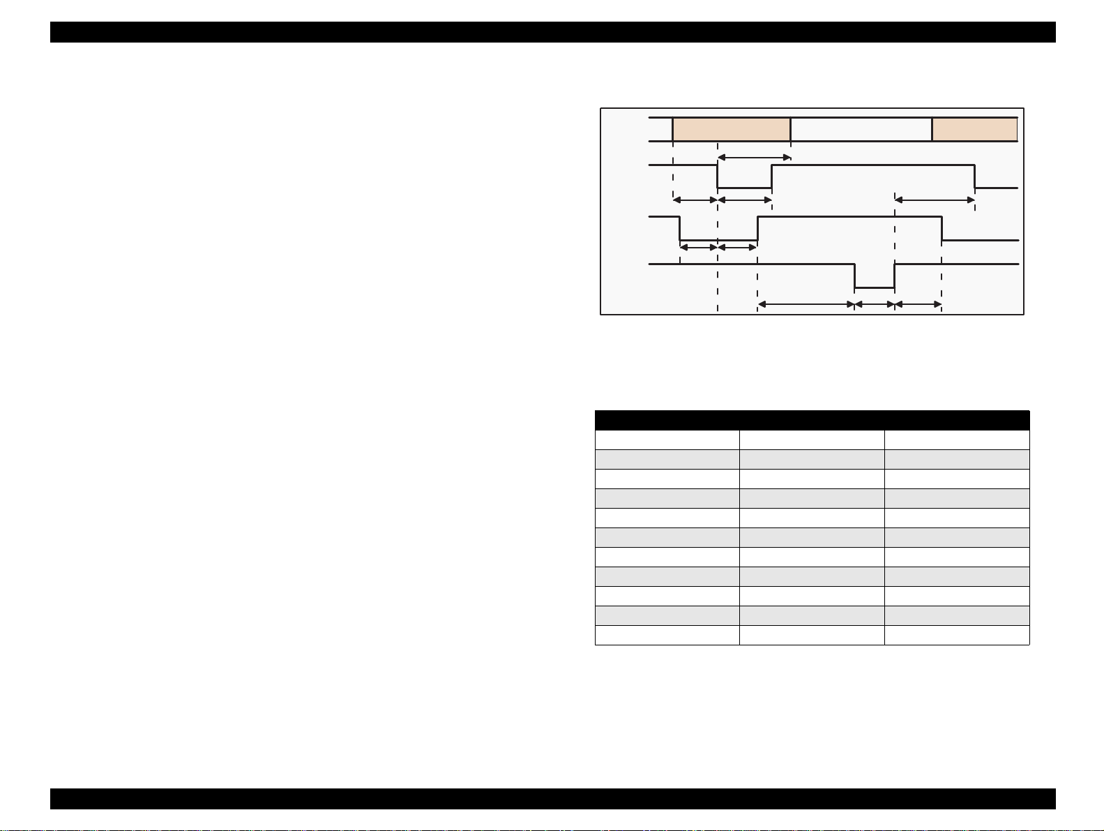
NOTE 3:Refer to Figure 1-9 for transmission timing of each signals.
NOTE 4:Do not perform data transmission ignoring /ACK or BUSY
signal. (Perform the data transmission after confirming that /
ACK and BUSY signals are Low.)
NOTE 5:It is possible to per form the printing test including interfac e circuit
without using equipment from outside when 8-bit data signal
(20-27 pin) is set to appropriate word code and connect them
forcefully to /ACK and /STRB.
Data
/STROBE
BUSY
/ACKNLG
Byte Data n
Tsetup
Tstrb
Tready Tbusy
Thold
Treply
Tack Tnbusy
Byte Data n+1
Tnext
Figure 1-9. Data Transmission Timing for Forward Channel
Table 1-13.
Maximum and Minimum Timing for Data Transmission
Parameter Minimum Maximum
tsetup 500ns ---
thold 500ns ---
tstb 500 ns ---
tready 0 ---
tbusy --- 500ns
tt-out* --- 120ns
tt-in** --- 200ns
treply 0 ---
tack 500ns 10us
tnbusy 0 ---
tnext 0 ---
* Rise and fall time of every output signal.
** Rise and fall time of every input signal. Typical timing for the tack
parameter is shown below.
Chapter 1 Product Description 29
Page 30
EPSON Stylus Color 440/640/740 Revision A
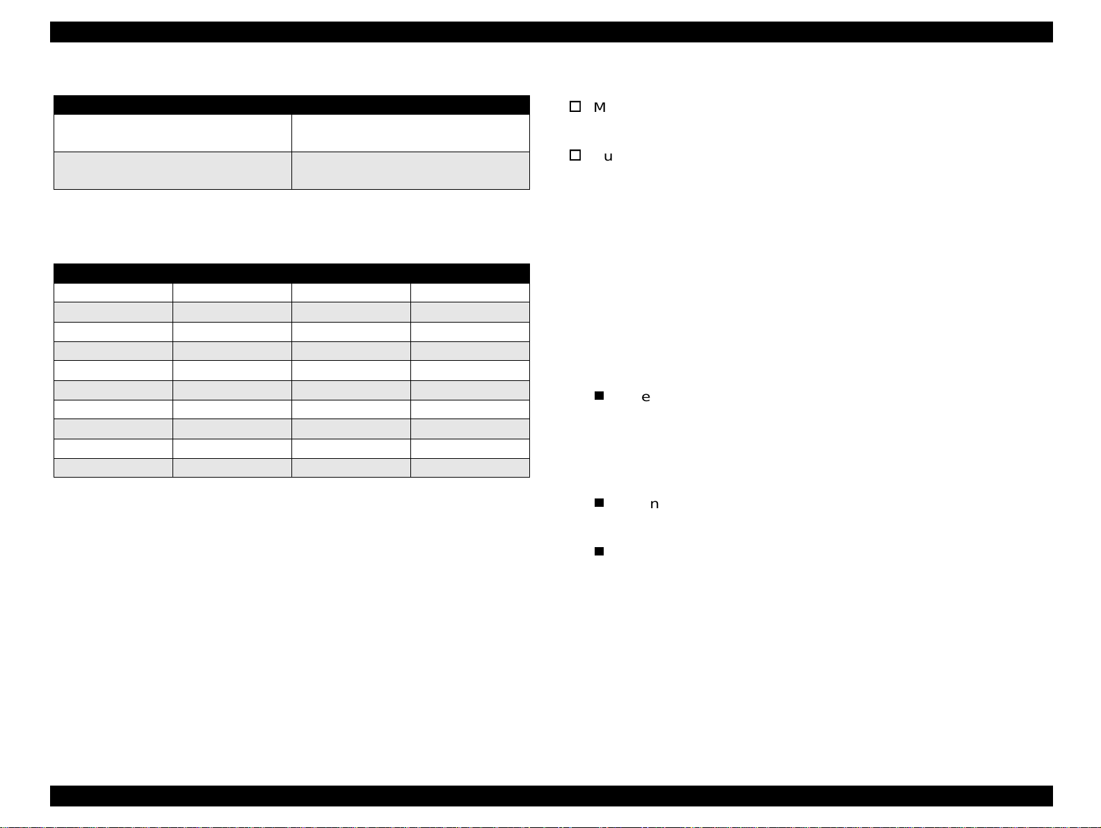
Table 1-14. Typical Tack Timing
Parallel I/F Mode Typical Tack Timing
High speed
Normal speed
2us (for Stylus Color 440,640)
1us (only for Stylus Color 740)
4us (for Stylus Color 440,640)
3us (only for Stylus Color 740)
Table 1-15. Signal level for TTL (IEEE-1284 level 1 device)
Parameters Minimum Maximum COndition
VOH* --- 5.5V
VOL* -0.5V ---
IOH* --- 0.32mA VOH = 2.4V
IOL --- 12mA VOL = 0.4V
CO --- 50pF
VIH --- 2.0V
VIL 0.8V ---
IIH --- 0.32m A VIH = 2.0V
IIL --- 12mA VIL = 0.8V
CI --- 50pF
NOTE:
A low logic level on the Logic H signal is 2.0V or less when the printer is
powered off and this signal is equal or exceeding 3.0V when the printer is
powered on. The receiver shall provide an impedance equivalent to 7.5K ohm
to ground.
1.3.2.1 Prevention Hosts from Data Transfer time-out
Generally, hosts abandon data t ransfer to periph erals when a peripheral
is in the busy state for dozens of seconds continuously. To prevent
hosts this kind of ti me-out, the print er receives dat a very s lowly, seve ral
bytes per minute, even if the printer is in busy state. This showdown is
started when the rest of the input buffer becomes several hundreds of
bytes. Finally, the printer is in the busy state continuously when the
input buffer is full.
1.3.2.2 Auto Interface Selection (for Stylus Color 640, 740)
Manual Selection:
One of two interfaces can be selected by the default setting mode.
Automatic Selection:
The automatic interface selection is enabled by the default setting
mode. In this automatic interface selection mode, the printer is
initialized to the idle state scanning which interface receives data
when it is powered on. Then the interface that receives data first is
selected. When the host stops data transfer an d the pr inter is in the
stand-by state for the seconds, the printer is ret u rned to the idle
state. As long as the host sends data or the printer interf ace is busy
state, the selected interface is let as it is.
Following explains conditions of other inte rfaces when a particular
interface is selected.
When the parallel interface is not selected, the interface gets
into BUSY state. At this time, LH s ignal is set to “ L”. That means
blocking power supply and no responds from 1284. Therefore, it
is necessary for the host, which requires Reverse transfer, to
check LH state.
When the serial interface is not selected, the interface sets the
DTR signal MARK.
When the printer is initialized or returned to the idl e state,
Parallel interface becomes the ready condition and DTR of serial
interface becomes SPACE (Low) condition and reset off-line bit
of Main Status Register (MNSTS)to, option interface.
Chapter 1 Product Description 30
Page 31

EPSON Stylus Color 440/640/740 Revision A
Pin #1
Pin #2
Pin #3
Pin #4
1.3.3 Serial Interface (for Stylus Color 640, 740)
[Standard] Based on RS-423
[Synchronization] Synchronous
[Bit Rate] Approx.1800Kbps
[Handshaking] X-ON/X-OFF, DTR Protocol
[Word Format] Data Bit= 8 bits
Parity Bit= None
Start Bit= 1 bit
Stop Bit= 1 bit
[Connector] 8-pin mini-circular connector
[Recommended Cable]Apple System Peripheral-8 Cable
Table 1-16. Pin Assignment
Pin No. Signal Name I/O Description
1 SCLK O Synchronous clock signal
2 CTS I Clear To Send
3 TXD- O Transmit Data (-)
4 SG I (Signal Ground)
5 RXD- I Receive Data (-)
6 TXD+ O Balanced Transmit Data (+)
7 DTR O Data Terminal Ready
8 RXD+ I Balanced Receive Data (+)
1.3.3.1 USB Interface (Only for Stylus Color 740)
[Standard] Universal Serial Bus Specifications Rev. 1.0
Universal Serial Bus Device Class Definition
for Printing Device Version 1.0
[Bit Rate] 12 M bps
[Data Encoding] NRZI
[Connector] USB Series B
[Recommended Cable Length] 2 meters
Table 1-18. Pin Assignment
Pin No. Signal Name I/O Description
1 Vcc ---2 -Data Bi-D Data
3 +Data Bi-D
4 Ground ---- Cable Ground
Cable power, Maxi. power c onsumption
is 100 mA
Data, pull up to +3.3 V via 1.5 K ohms
resistor
Table 1-17. X-On/X-Off and DTR Status
State Buffer Space X-ON/X-OFF DTR
Busy Less than 3072 bytes Send X-OFF code OFF
Ready More than 5120 bytes Send X-ON code ON
Figure 1-10. USB Pin Assignment
Chapter 1 Product Description 31
Page 32

EPSON Stylus Color 440/640/740 Revision A
1.4 Control Panel
Since Stylus Color 440, 640, 740 does not require many buttons sinc e
printer driver can start various setti ngs and mo tions. Therefore, there
are only 2 non-lock type push switches, 1 lock type push switch and 4
LEDs. Figure 1-11 shows control panel of Stylus Color 440/640/740.
Paper Out LED
Ink Out(Bk)LED
Ink Out(CMY)LED
Cleaning Switch
(Ink maintenance)
Load/Eject Switch
Power on Switch
Stylus Color 440, 640
Power LED
1.4.1 Indicators (LEDs)
(1) Power
Lights when the operate switch is “ON”, and AC power is supplied.
(2) Paper out
Lights during the paper-out condition, and blinks during the paperjam condition.
(3) Ink Out (Black)
Lights during no Black ink condition, and blinks during the Black
ink low condition.
(4) Ink Out (Color)
Lights during no Color ink condition, and blinks during the Color ink
low condition.
Stylus Color 740
Figure 1-11. Control Panel Over Viewing
Chapter 1 Product Description 32
Page 33

EPSON Stylus Color 440/640/740 Revision A
1.4.2 Panel Functions
Refer to Table 1-19 to Table 1-21.
Table 1-19. Panel Functions
Switch Function
Load/Eject
(within 2 sec.)
Load/Eject
(for 2 sec.)
Cleaning
(for 2 sec.)
Cleaning
(within 2 sec.)
Switch Function
Load/Eject 1) Starts the status print. (*1)
Cleaning
Load/Eject
+
Cleaning
NOTE 1:You can check the 1) firmware version, 2) protection counter
and 3) nozzle check pattern by performing this f unction.
NOTE 2:The code pages for Stylus Color 440, 640 are not opened.
NOTE 3:Since Stylus Color 740 have 2 specificati ons both the standard
and NLSP version, user can select some parameter and a
character table by communicating with the printed li st.
NOTE 4:After you enter this EEPROM reset mode, go to Table 1-21.
1. Loads or ejects a paper.
2. When the carriage is on the I/C replacement position, return
the carriage to the capping position.
1. Starts the I/C replacement sequence.
1. Starts the printhead cleaning sequence.
2. In case it’s in the ink low or ink out condition, starts the I/C
replacement sequence.
1. When carriage is on the I/C replacement position, return the
carriage to the capping position.
Table 1-20. Panel Function with Power On
<Stylus Color 440, 640>
Changes the code page. (*2)
<Stylus Color 740>
Enters the Default setting mode. (*3)
Enters the EEPROM Reset mode. (The Lo ad/ Ejec t L ED bl in ks
for a few seconds.)
(Used only for resetting the maintenance error.) (*4)
Table 1-21. EEPROM Reset
Switch Function
Cleaning Resets the EEPROM. (*5)
1. While the Load/Eject LED is blinking (for about 2 seconds),
press down the Cleaning switch for 10 seconds.
CAUTION
The following steps vary depending on the printer.
2. [Stylus Color 440/640]
After 10 seconds, both Bk and CMY ink LEDs come ON
simultaneously.
[Stylus Color 740]
After 10 seconds, Load/Eject, Bk and CMY ink LEDs all
blink
simultaneously.
3. [Stylus Color 440/640]
Confirming the both LEDs are ON, release the Cleaning
switch. The printer automatically starts initialization
operation to reset the specified addresses in the EEPROM.
[Stylus Color 740]
Confirming all 3 LEDs are
switch. The printer automatically starts initialization
operation to reset the specified addresses in the EEPROM.
blinking
, release the Cleaning
NOTE 5:Before you press the Load / Eject switch, be sure to ent er the
EEPROM reset mode, referring to Table 1-20.
CAUTION
You can reset the below addresses in a EEPROM by
performing the EEPROM Reset operation.
1. 1) Timer Counter (Power Off time) IC value
2. I/F selection returns to Auto
3. Protection Counter value
CAUTION
Even though you repeat the EEPROM reset operation,
it does not perform initialization but only resets the
EEPROM addresses. Wheater or not to permorm
initialization depends on the power off time monitored
by the timer IC.
Chapter 1 Product Description 33
Page 34

EPSON Stylus Color 440/640/740 Revision A
1.4.3 Printer Condition and Panel Status
Table 1-22 shows printer condition and panel status. Since the table
shows various error status and also indicates printer status, it enables
you to find appropriate repair ways.
Table 1-22. Printer Condition and LED Status
Printer Status
Power on condition --- --- --- --- 9
Ink Sequence mode On --- --- --- 6
I/C replacement mode Blink --- --- --- 5
Data processing Blink --- --- --- 8
Paper out Blink --- --- On 4
Paper jam --- Off Off Blink 3
No I/C, Ink out (bk) --- On --- --- 7
Ink level low (bk) --- Blink --- --- 7
No I/C, Ink out (CMY) --- --- On --- 7
Ink level low (CMY) --- --- Blink --- 7
Enters the EEPROM Reset --- ON (for 3 seconds) --Maintenance Request Blink Blink Blink Blink 2
Fatal Error Blink On On Blink 1
Power Ink Out (Black) Ink Out (CMY) Paper Out
Indicators
Priority
Chapter 1 Product Description 34
Page 35

EPSON Stylus Color 440/640/740 Revision A
1.5 Error Status
When following status occur, the printer goes to the error status and
stops taking data, setting the /ERROR signal in the interface as “Low”,
and Busy signal as “High”. At t his ti me, t he prin ter goes to non pr in table
status. Refer to Section 1.4.3 for more details of LED Panel indicators
during the various error status.
1.5.1 Ink Out
When the printer runs out the most part of the ink of any one color, it
warns ink-low and keeps printing. When the printer runs out the whole
ink of any one color, it stops printing and indicates ink-ou t error. User is
requested to install a new ink-cart ridge in this state. A ink -cartridge once
taken out should never be used again. Re-installation of the cartridge
not filled fully upsets the ink level detec tion and may cause a serious
problem in the print head as a result.
CAUTION
The following explains the warning sign above.
Never use the ink cartridge that has been removed.
[Step 2]
Even after the bubble absorbing ability described above stops, there is
problem about entering bubbles as long as the ink cartridge is installed
in the printer. However, if the ink cartridge which does not have
absorbing ability any more is once removed from the printer, new
coming bubbles into the cartridge will never disappear naturally. These
bubbles may cause not only printing malfunct ion but also thic kening ink.
This thickened ink goes into the head and clogs ink path in the head or
nozzle and may cause serious head damage.
[Step 3]
As standard specification for Stylus Color 400, ink consumption count er
is reset when the ink cartridge is re moved. If an ink cartrid ge is removed
and re-installed unnecessarily the v alue on the ink consump tion monitor
which the user can check will be wrong and printer may keep printing
even though the ink cartridge is installed empty. This may cause head
damage.
1.5.2 Paper Out
When the printer fails to load a sheet after power on operation includ ing
timer-cleaning is done and Load/Eject button on the FF command or
operation panel is pressed, it goes into a paper out error.
[Step 1]
After the cartridge is once taken out, bubbles come in from the ink
supply hole located at the top of cartridge and are absorbed into the
head during printing. AS a result, the head is unable to discharge ink
properly. Also, inevitabl e e ntry of bubbles created during installation of
a new ink cartridge can be absorbed to ink itself since the ink in the
cartridge is deaerated during the production process. However, this
ability for absorption can last only abou t one hour after the cartridge is
installed.
1.5.3 Paper Jam
When the printer fails to eject a sheet even after feeding motion is
completed or Load/Eject button on the FF command or operation panel
is pressed, it goes into a paper jam error.
Chapter 1 Product Description 35
Page 36

EPSON Stylus Color 440/640/740 Revision A
1.5.4 No Ink-Cartridge
Following reasons can be the causes when printer goes this error
mode.
1. When the printer is turned on for the first time. (This is a normal
error state and it returns to the normal state after installing an ink
cartridge according to the ink cartridge exchange operation.)
2. Ink cartridge exchange operation i s done correctly. After t he position
of carriage is moved by exchange operation, if the cleaning swit ch is
pushed without installing ink cartridge or if the carriage returns to
the home-position automatically without doi ng any operation, it is
considered as handling mistake. However , it ret urns to normal st ate
by performing ink exchange operation again and installing cartridge
correctly.
3. If “No ink-cartridge error” appear s even after the ink cartridge is
installed, the printer must be something wrong and around the
sensor area in the carriage need to be repaired.
4. If sometimes printer can pri nt normal ly but als o sometimes “ No ink cartridge error” appears, the printer must be something wrong.
(Same reason as above)
1.5.5 Maintenance Request
When the total quantity of ink wasted through the cleanings and flushing
reaches to the limit, printer indicates this error and stops. The absorber
in the printer enclosure is needed to be replaced with new one by a
service person. The ink quantity that is absorbed by the absorber
(waste ink pad) is monitored by the software counter as “t otal ink
counter”. This counter is added by point system and absorber’s
maximum ability is set at the following reference value.
Stylus Color 440 Maximum Counter Point: 21000 Point
Stylus Color 640 Maximum Counter Point: 19800 Point
Stylus Color 740 Maximum Counter Point: 40900 Point
NOTE:Since 1 point of counter point equals 0.02 ml, the actual ink
amount becomes;
Stylus Color 440 Maximum Ink Capacity: 420 ml
Stylus Color 640 Maximum Ink Capacity: 396 ml
Stylus Color 740 Maximum Ink Capacity: 818 ml
1.5.6 Fatal Errors
When the printer detects fatal errors such as carriage control error or
CG access error, it enters a fatal error mode, as described bel ow.
1) Carriage control Error:
Parallel adjustment malfunction
Home-position malfunction
Timing belt tension malfunction, short age of lubricant on the
carriage guide shaft, etc.
2) CG Access Error:
Short circuit, etc.
Chapter 1 Product Description 36
Page 37

EPSON Stylus Color 440/640/740 Revision A
1.6 Printer Initialization
Stylus Color 440, 640, 740 have three kinds of initialization methods.
Following explains each initialization.
[1.Power-on initialization]
This printer is initialized when turning the printer power on, or printer
recognized the cold-reset command (remote RS command). When
printer is initialized, following action is performed.
(a) Initializes pr inter mechanism.
(b) Clears input data buffer.
(c) Clears print buffer.
(d) Sets default values.
[2.Operator initialization]
This printer is initialized when turning the printer power on again within
10 seconds from last power off, or printer recognize the /INIT signal
(negative pulse) of parallel interface. When printer is initialized,
following action is performed.
1.7 Initialization Settings
Stylus Color 440, 640, 740 initializes following settings when the
initialization is performed. Also, if the user changes the settings in the
Panel setting mode, Default setting or Remote command sett ing, values
or settings which are possibl e to be st ored are ini t iali zed as i nit iali zati on
settings.
Page position: Page heading location for current page
Line spacing: 1/6 inch
Right margin position:80 lines
First
Left margin position:
Character pitch: 10CPI
Printing mode: Text mode (Not Raster graphics mode)
line
(a) Cap the printer head.
(b) Eject a paper.
(c) Clears input data buffer.
(d) Clears print buffer.
(e) Sets default values.
[3. Software initializa tion]
The ESC@ command also initialize the printer. When printer is
initialized, following action is performed.
(a) Clears print buffer.
(b) Sets default values.
Chapter 1 Product Description 37
Page 38

EPSON Stylus Color 440/640/740 Revision A
1.8 Main Components
Stylus Color 440, 640, 740 have following major units. Also, it is one of
the major characteristics that the bottom of the Pri n ter mechanism
serves as the Lower case at the same time. Each unit from 2) to 5) are
simply explained below:
1) Upper Case
2) Printer Mechanism
3) Main Control Board
Stylus Color 440:C206 Main-B Board, C255 Main Board
Stylus Color 640:C256 Main Board
Stylus Color 740:C257 Main Board
4) Power Supply Board
Stylus Color 440:C206 PSB/PSE Board
Stylus Color 640:C206 PSB/PSE Board
Stylus Color 740:C257 PSB/PSE Board
5) Control Panel Board
Stylus Color 440:C206 PNL Board
Stylus Color 640:C206 PNL Board
Stylus Color 740:C209 PNL Board
1.8.1 Printer Mechanism
Like the previous printer mechanism such as for Stylus Color 400, 600,
and Stylus Photo, one of the major characteristics of Stylus Color 440,
640, 740 is that the printers have no Engage/Disengage mechanism to
change between the pump mechanism and paper feeding mechanism.
In stead, this change-over control is done by the distinction between
turning direction of PF/Pump motor and position of present carriage
unit. Also, another major characteristic is that printhead is on unit
combining black and color.
Chapter 1 Product Description 38
Page 39

EPSON Stylus Color 440/640/740 Revision A
1.8.2 C206 Main-B Board (Stylus Color 440)
C206 Main-B board controls Stylus Color 440 and consists of fol lowing
major electric elements. Thi s board will be changed to new boar d called
C255 Main board.
IC 14(PF)IC 15(C R )
CN1
IC 1 (C P U )
CN6CN7
CN10
IC 7(H ead)
CN8
EEPRO M
(IC 1 1 )
Q 7,Q 9(H ead)
IC 2 (A s ic )
Figure 1-12. C206 Main-B Major Electric Elements
IC 3 (P -R O M )
CN3
B a tt 1
CN5
CN4
CN11
IC 4 (4 M D -R A M )
1.8.3 C256 Main Board (Stylus Color 640)
C256 Main board controls Stylus Color 640 and consists of following
major electric elements.
IC 15(C R )
CN10
IC 7(H ead)
IC 14(PF)
CN6CN7
CN8
Q 7,Q 9(H ead)
CN1
IC 1 (C P U )
IC 2 (A s ic )
Figure 1-13. C256 Main Board Major Electric Elements
IC 16(P-R O M )
CN2
B a tt 1
IC 6
IC 5 (4 M D -R A M )
CN3
CN5
CN4
CN11
Chapter 1 Product Description 39
Page 40

EPSON Stylus Color 440/640/740 Revision A
1.8.4 C257 Main Board (Stylus Color 740)
C257 Main board controls Stylus Color 640 and consists of followi ng
major electric elements.
IC 14(H ead)
CN9
CN7
IC 1 5
HT1
IC 1 2 IC 1 3
(P F D rive )
(R e g u ra to r)
CN8
IC11(CR)
Figure 1-14. C257 Main Board Major Electric Elements
IC 6 (C G :o n ly fo r N L S P )
IC 3 (P -R O M )
CN3
CN1
B a tt 1
IC 4 IC 5
(4M DRAMx2)
IC 1 (C P U )
IC 2 (A s ic )
IC7(EEPRO M )
CN2
CN3
CN5
CN4
CN11
1.8.5 Power Supply Board C206 PSB/PSE (Stylus Color 440, 640) C257 PSB/PSE (Stylus Color 740)
In the electric boards for Stylus Color 440, 640, 740, a switching
regulator method is used and supplies stable logic and power voltages
constantly. Also, since this C206/C257 PSB board ha secondly type
switch for its circuit system, it is possi ble to keep supplyi ng electri city to
the C206main-B/C255/C256/C257 main control board for 30 seconds
even after the power switch is turned off. Using this time diff erence,
even when mis-operation is done by the user such as turning off the
power during the middle of printing work, it prevents thickened ink from
attaching around the nozzle plate by transferring the head to cap
position.
Q1(FET)
Fuse(F1)
Trans(T1)
C51
CN1
Filter(L1)
PC1
C11
IC51
CN2
Figure 1-15. C206/C257 PSB/PSE Board Major Electric Elements
Chapter 1 Product Description 40
Page 41

EPSON Stylus Color 440/640/740 Revision A
1.8.6 C206 PNL Board (Stylus Color 440, 640)
Panel board (C206 PNL board) is located in the panel case where is in
the right bottom of the front printer and consists of 3 switches, 4 LEDs
and 1 connector.
LED0
LED1
LED2
SW2
SW0
Figure 1-16. C206 PNL Board
LED4
SW1
1.8.7 C209 PNL Board (Stylus Color 740)
Panel board (C209 PNL board) is located in the panel case where is in
the right bottom of the front printer and consists of 3 switches, 4 LEDs
and 1 connector.
LED0
LED4
LED1
LED2
SW2
SW0
SW1
CN1
Figure 1-17. C209 PNL Board
Chapter 1 Product Description 41
Page 42

OPERATING PRINCIPLES
Page 43

EPSON Stylus Color 440/640/740 Revision A
2.1 Overview
This section describes the operating princi ples of the printer mechanism
and the electric circuit board.
Electronic Boards for Stylus Color 440 are;
Main: C206 Main-B, C255 Main Board
Power Supply: C206 PSB,PSE Board
Panel: C206 PNL Board
Electronic Boards for Stylus Color 640 are;
Main: C256 Main Board
Power Supply: C206 PSB,PSE Board
Panel: C206 PNL Board
Electronic Boards for Stylus Color 740 are;
Main: C257 Main Board
Power Supply: C257 PSB,PSE Board
Panel: C209 PNL Board
Chapter 2 Operating Principles 43
Page 44

EPSON Stylus Color 440/640/740 Revision A
2.1.1 Printer Mechanism
Like previous EPSON Ink Jet printers such as Stylus Color 400, 600,
Photo, Photo 700, Photo EX, the printer mechanism of Stylus Color
440/640/740 does not have an exclusive mechanism to change over
paper feeding and pumping operation. In stead, this control is done by
the turning direction of paper feed/pump motor and posi ti on of the
carriage at that time. Also, t he print heads of these prin ters combine the
black and CMY heads in one unit. The followings indicate the nozzle
configurations of these 3 models.
Stylus Color 440:
Black Nozzle: 64 nozzles(90 dpi x 2 rows in staggered)
CMY Nozzle: 21 nozzles/colors(90 dpi x 1 row)
Stylus Color 640:
Black Nozzle: 64 nozzles(90 dpi x 2 rows in staggered)
CMY Nozzle: 32 nozzles/colors(90 dpi x 1 row)
Stylus Color 740:
Black Nozzle: 144 nozzles(120 dpi x 3 rows in staggered)
CMY Nozzle: 48 nozzles/colors(120 dpi x 1 row)
Among these printers, the Stylus Color 640 and 740 can print 1440 (H)
x 720(V) resolution like Stylus Color 800 and Pro5000. On the other
hand, the Stylus Color 440 can print real 720 dpi(720 (H) x 720(V))
resolution like Stylus Pro XL.
PF Roller Drive
Hopper
Drive
Pump
Drive
Carriage Unit
(Print Head Unit)
Timing
Belt
Paper Load
Trigger Lever
Pump Position
Paper Feed
Motor
Carriage Motor
Figure 2-1 in the in the right column shows the outline of the printer
mechanism.
Figure 2-1. Printer Mechanism Block Diagram
Chapter 2 Operating Principles 44
Page 45

EPSON Stylus Color 440/640/740 Revision A
2.1.1.1 Printing Mechanism
Basic principles of the print head which plays major role of printing
mechanism is the same as previous models; on demand type MACH
head method, but there is some difference in the resolution. (Refer to
figure1-1)
Also, unlike Stylus Color IIs, 820, 200 automatic correction type, in
order to fix the dispersion of mufti layer piezo electric element which is
used for driving each nozzles, it is necessary to input the VH value
written on the side of print head by using exclusive program when you
replace print head, control board, or the printer mechanism.(However,
there are no resistor array to decide the VH volt age on the main control
board.) Following explains print head.
PZT
PZT is an abbreviation of Piezo Electric Element. Print signal from
the PSB/PSE board is sent through the driver board on the print
head unit and to the PZT. Then, the PZT pushes the top cavity
which has ink stored, and make the ink discha rge f rom each nozzle
located on the nozzle plate.
Cavity Set
Ink which is absorb ed from ink cartri dge go throug h the f ilter and will
be stored temporarily i n this tan k, which is called “cavi ty” until PZT is
driven.
PZT
Nozzle Plate
Figure 2-2. Print Head Sectional Drawing
Nozzle Selector Board
I/C Sensor's actuator
Stylus Color 440,640
I/C Sensor's actuator
Stylus Color 740
(Ink Cartridge)
Cavity
Needle
Filter
Nozzle Plate
The board with nozzle holes on the printer head surface is called
Nozzle Plate.
Filter
When the ink cartridge is installed, if any dir t or dust around the
cartridge needles are absorbed into the head inside, there is a gre at
possibility of causing nozzle clog and disturbance of ink flow and
finally causing alignment fai lure and dot-missi ng. In order to prevent
this, filter is set at cartridge needle below and ink is once filtered
here.
Chapter 2 Operating Principles 45
Page 46

EPSON Stylus Color 440/640/740 Revision A
2.1.1.2 Printing Process
Following figures show the sectional drawings of normal state and
ejecting state of the printhead.
1.
Normal State:
When the print signal is not output, PTZ also does not move in the
waiting state (normal state). (Refer to Figure 2-3.)
2.
Ejecting State:
When the print signal is output from the C206 main-B/C255/C256/
C257 main board, IC (IR2C72C:Nozzle Selector) located on the
Print head unit latches the data once by 1-byte unit. Appropri ate
PZT latched by nozzle selector is pushed into the cavity by appl ying
common voltage from the main board. By this operation, ink that is
stored in the cavity pops out from nozzles. (Refer to figure 2-4.)
Ink Course
Figure 2-3. Print Head Normal State
PZT
Nozzle
Cavity
Nozzle Plate
Figure 2-4. Print Head Ejecting State
Chapter 2 Operating Principles 46
Page 47

EPSON Stylus Color 440/640/740 Revision A
2.1.1.3 Carriage Mechanism
Carriage mechanism is to drive the carriage with print head mounted
from left to right or vice ver sa. The carriage d rive motor i n these pri nters
are a 4-phase, 200-pole, stepping motor and is driven by 1-2 phase, 2-2
phase and W1-2 phase drive method for Stylus Color 440, 460, and by
2-2 phase 1-2 phase, W1-2 phase, 2W1-2 phase and 4W1-2 phase
drive method for Stylus Color 740. This stepping motor allows the
carriage to move freely to
the particular positions which is necessary for various operation, such
as paper feeding, ink absorbing, flashing, ink exchange and cleaning
operations. The tables below show carriage motor specifications and
motor controls at each mode.
Table 2-1. Carriage Motor Specifications
Items Description
Motor type 4-Phase/200-pole Stepping motor
Drive voltage Range 42VDC ± 5%
Internal coil resistance 7.8 Ohms ± 10%(per phase under 25 °C
environment)
Driving Speed(frequenc y)
Range[csp(Hz)]
Control method Bi-Pola Drive
5(60)∼340(4080)
Table 2-3. Motor Control at Each Modes (Stylus Color 740)
Printing mode
High Speed Skip 340 4080
Normal Printing 200 2400 W1-2, 2-2 phase drive
Capping 80 960 2W1-2, 2-2 phase drive
Wiping 40 480 2W1-2, 2-2 phase drive
Cap (Valve
Release)
Withdrawal of cap 5 60 4W1-2, 2-2 phase drive
Drive Speed
[CPS]
20 240 4W1-2, 2-2 phase drive
Drive frequency
[PPS]
1
A
3
/A
Drive method
W1-2, 2-2,1-2
phase drive*
Rotor
2
Table 2-2. Motor Control at Each Modes (Stylus Color 440, 640)
Printing mode
High Speed Skip 340 4080
Normal Printing 200 2400 W1-2, 2-2 phase drive
Capping 80 960 W1-2, 2-2 phase drive
Wiping 40 480 W1-2, 2-2 phase drive
Cap
(Valve Release)
Withdrawal of cap 5 60 W1-2, 2-2 phase drive
Drive Speed
[CPS]
20 240 W1-2, 2-2 phase drive
Drive frequency
[PPS]
Drive method
W1-2, 2-2,1-2
phase drive*
Figure 2-5. CR (PF) Motor Internal Circuit Diagram
B
4
/B
Chapter 2 Operating Principles 47
Page 48

EPSON Stylus Color 440/640/740 Revision A
See Figure 2-6 which shows the carriage mechanism.
Paper Feed Motor
Eject Roller
PF Roller
Paper guide(Front)
Carriage home position Sensor
Timing Belt
Carriage Unit
Front Side
Carriage
Guide Shaft
Carriage Motor
Rear Side
Parallelism
Adjust Lever
Fixing Bush
Figure 2-6. Carriage Mechanism (Top view)
The printhead, a core of the printing mechanism, is stored in the
carriage unit. When the adjustment lever is moved up and down, this
printhead maintains the printhead t il t i n a flexi b le and adjustable
structure, using a tilt adjustment mechanism. Also, the parallelism
adjustment lever, mounted on the left and right sides of the carriage
guide shaft, adjusts paralleli sm between the pl aten and shaft when the
shaft is installed to the printer mechanism. After this adjustment is
completed, moving PG adjustment lever changes space between the
platen surface and the print head surface to one of two possibi lities:
either 1.04 mm or 1.74mm. It is possible to vary the space between
platen surface and print head by rotating the shaft s of the carriage guide
shaft which itself is decentralized, with the operation of PG lever. This is
the mechanism that the user can use to adj ust the appropriat e PG value
according to the printing result or any other environmental conditions
such as paper curl.
Carriage lock mechanism is to prevent the carr iage from bein g left at an
uncapped position for a long ti me because of vibration dur ing the printer
transport or mishandling by the users. If the c arriage is left uncapped for
long time, ink on the print head surface gradually becomes thick. As a
result, the nozzle will be unable to discharge ink.
To make matters worse, the holes (crater) of nozzle may be completely
clogged by the thick ink and it may not be able to return to the normal
condition just by cleaning operation. In order to prevent this, printer
goes to carriage lock state at the fol lowing conditions. (See the f ollowing
page.)
After Power OFF operation:
If the power is turned off on the way of printing or any other
performance, carriage lock will be performed in the end after
completing initialize operation.
After power ON operation:
After power is turned on and automat ic P-On Cleaning is performed,
then carriage lock will be p erformed. P-On Cl eaning i s an auto mati c
head cleaning that is performed when the power is turned on. The
timer IC always calculates printer’s power OFF time by the power of
lithium battery mounted on the C206 Main-B/C255/C256 /C257 Main
board. P-on cleaning function automatically selects the cleaning
level according to the time which the printer is not in
used.
After Eject the paper:
After Load/Eject button is pressed and the paper is ejected, if the
data is not input, the printer performs carriage lock and goes to
standby state. However, if the paper is loaded to the print er inside
by Load/Eject button, the printer does not perfo rm carriage lock
operation.
Chapter 2 Operating Principles 48
Page 49

EPSON Stylus Color 440/640/740 Revision A
2.1.1.3.1 Platen Gap Adjust Mechanism and Parallel adjustment Mechanism
This mechanism can be set by the users and can prevent various
problems related to low image density or print with any dirt by changing
the positions of PG lever according to the paper types.
Table 2-4.
Paper Lever Position PG adjustment value
All Media Front 0 mm
If you find any print
problems
Rear 0.7mm
Platen Gap Adjust Lever Setting
(1.04mm between head and platen)
(1.07mm between head and platen)
It is a major premise that parallel adj ustment is done correctly for the
space between head and platen (PG adjustment value above) which
can be changed by platen gap adjustment. Parallel adjustment should
be done when the serviceman mounts the carriage guide shaft on the
printer mechanism during the production process or repair service. In
the adjustment, the space between parallel adjust m ent lever and gage
should be 1.04 mm.
2.1.1.4 Paper Feed Mechanism and Pump Mechanism
Mechanisms that send the paper in the hopper to inside the pr inter and
perform constant paper feed in order to perform printing on the sent
paper are called paper feed mechanism as generic name. In the Stylus
Color 440/640/740, 4 phase hybrid type pulse motor is used in the PF
motor as a motive power motor as a motive power of the paper
mechanism and driving is done at 2-2, 1-2 phase drive method for
Stylus Color 440, 640 and at 2W1-2, W1-2, 1-2 and 2-2 phase drive
method for Stylus Color 740. This motor is not only used as a power
source for paper feed mechanism but also used as power source of
pump mechanism which is necessary for print head cleaning . By using
this pulse motor, it becomes possible to use high speed driver or
intermittent drive for the various pape r feeds and pump operati ons such
as paper feed, slight paper feed, high and low speed absorption of
pump operations. Following tables show PF motor specifications and
control method at each mode.
Table 2-5.
Item Description
Motor type 4-phase/48-pole Stepping motor
Drive voltage 42VDC ± 5%
Coil Resistance 7 Ohms ± 10%(per 1 phase under 25°C
Drive frequency [Hz] 100-1990 Hz
Control method Bi-Pola Drive
PF Motor Specifications (Stylus Color 440, 640)
environment)
Table 2-6. PF Motor Specifications (Stylus Color 740)
Motor type 4-phase/200-pole Stepping motor
Drive voltage 42VDC ± 5%
Coil Resistance 8.8hms ± 10%(per 1 phase under 25°C
environment)
Drive frequency [Hz] 100-3240 Hz
Control method Bi-Pola Drive
Chapter 2 Operating Principles 49
Page 50

EPSON Stylus Color 440/640/740 Revision A
Papers on the ASF (auto-sheet -feeder ) suppl ie d by the user ar e carr ie d
to the printer inside by paper pick up sequence. Unlike the previous
models, ASF of Stylus Color 440/640/740 has mufti feed prevention
mechanism. Following explains this function and figure below shows its
mechanism.
[1. Multi-feed prevention mechanism]
When the Load/Eject button is pressed, reverse d rotation of PF motor is
performed. The return lever resets papers which are already in the out
of stand by position in the stand by position and make it possible to
perform stable paper feeding by picking up the paper again. Following
explains process of multi-feed prevention st ep by step. Refer to the
figure above and confirm its operation.
Pintch Roller
D-Cut Roller CAM
Return Lever
[Standby state] [Returning state]
Pad
Hopper
Hopper spring
Pad spring
2)
1)
2)
[Step 1]
When the load/Eject switch is press ed or p rinting or der is input from
the PC, PF motor rotates counterclockwise and makes the CAM
rotate towards direction of 1 in the figure above.
[Step 2]
When the CAM covers the notch by the return lever, that position is
considered as home position, being monitored by ASF sensor.
[Step 3]
When the CAM rotates toward 1 in the figure above, the return lever
is pushed by the notch of CAM and falls towards 2. At this time, the
return lever moves to direction 3 by this motion, and push down the
pad which is waiting in the below part. At this time, friction of pinch
roller and pad will be canceled.
[Step 4]
The papers which are out of s tand by posit ion by the pre vious paper
feed motion are returned to the paper stand by position by flip over
strength of return lever. After this, PF motor rotates clockwise and
the printer goes to pick up sequence.
In the paper pick up mechanism of Stylus Color 440/640/740, same
mechanism as Stylus Color 400, 600, Photo, Photo EX are appli ed. This
mechanism changes adjoined lines of gear by colliding trigger leve r with
carriage unit and convey the motive power on the platen to the ASF side
(paper roller). The figure below shows mechanism with explanation.
Figure 2-7. ASF Unit Operation
Chapter 2 Operating Principles 50
Page 51

EPSON Stylus Color 440/640/740 Revision A
[2. Paper pick up mechanism]
When the Load/Eject switch is pressed or printing ord e r is input, the
carriage unit moves until the left edge and coll ides with paper pick up
trigger lever. When the carriage collides with this tr igger level, a
planetary gear located on the same axis is also pushed at the same
time and conveys the motive power on the platen to the adjoined gear
line side for ASF drive.
ASF Roller Drive Gear
Planetary Gear
ASF Roller Transmission Gear
Platen Roller Drive Gear
Paper Pick Up
Trigger Lever
Eject Roller Drive Gear
Eject Roller
Transmission Gear
PF Motor Pinion Gear
Platen Roller Transmission Gear
Paper eject notched roller solves the deflecti on of paper that is in the
between platen eject notched roller and paper eject rol ler and always
keep a certain space between print head and paper surface. For an
unique point, the securing angle of Eject Notched Roller has been
changed by 5 degrees compared wit h the previous products. Du e to this
change, the bottom margins of t hese printers are expanded from 14 mm
to 3 mm.
[Previous]
Eject Notched Roller
Paper
Eject Roller
Print Head
Platen
Support Roller
PF Roller
Bottom Margin 3 mm
Touch on the print head surface.
[Stylus Color 440,640,740]
Figure 2-8. Paper Pick up Mechanism
5 degrees
[3. Paper feed mechanism]
After papers in the ASF receive controls from pick up and multi feed
prevention mechanism, they are sent to the printer inside. The papers
picked up by paper roller in the ASF goes to between platen and roller
support. Also, the eject roller pushes out the paper completely until the
Steady
end and the roller support drops the paper in the eject tray. The eject
roller is driven with an eject paper notched roll er as pair where is
Figure 2-9. Paper Feed Mechanism
located on the paper eject roller.
Chapter 2 Operating Principles 51
Page 52

EPSON Stylus Color 440/640/740 Revision A
2.1.1.5 Ink System
Ink system mechanism consists of 1)cap mechanism, 2)pump
mechanism, carriage lock mechanism, 4)waste i nk absorber and 5)ink
sequence. Out of these mechanism, from 1) to 4) are physical
mechanism and parts which are mount ed on the prin ter mechanism and
5) ink sequence is performed automatically by firmware. Also, unlike
previous models, since Stylus Color 440/640/74 0 has no engage/
disengage mechanism to change over pump mechanism and paper
feed mechanism, it is one of the major characterist ics that pump and
platen are always at work whenever the PF motor is driven. The figure
below shows head positions when the ink system and various ink
sequence are performed.
FG
Printable Area
2976 dot(360-dpi)
ABCDE
A: Dummy Pumping Position(CRHP)
B: Ink Dischage Position
C: Flashing Position
D: Wiping Complete/Rubbing start Position
E: I/C Replacement Position
F: ASF Pick up Position
Eject Roller
Drive Gear
Eject Roller
TransmissionGear
PF(Pump) Motor
Pinion Gear
PF Roller Drive Gear
Carriage Lock Lever
Cleaner Blade
Pump Roller
Cap Unit
Figure 2-10. Ink System Mechanism
Figure 2-11.
Major Ink Sequence Position on Carriage Working Area
Chapter 2 Operating Principles 52
Page 53

EPSON Stylus Color 440/640/740 Revision A
2.1.1.6 Pump, Carriage Lock, Head Cleaner Mechanism
In the Stylus Color 440/640/740, there is no switch or mechanism to
change over the pump/paper feed mechanism. Therefore, whenever
the paper feed/pump motor rotate, pump drive roll er in the pump unit
inside rotates. However, ink absorption/non ink absorption are
separated by the roller rotational directio n. Also, even if the pump driver
rotates toward ink absorption and the carriage position is in the false
absorption position, only driving in the pump mechanism is performed
and actual ink attraction is not done. Figure 5-2 shows process of
conveying motive power to the pump drive roller.
See Figure 1-12. The process of conveying the motive power to the
paper eject roller by rotating the pinion of PF motor is descried in f igure
2-10. This motive power is convey ed to the Gear C thr ough the Gear B.
In the figure above, although the lever i n order to dri ve Gear C, carriage
lock, head cleaner mechanism is sho wn separately, it is constructed as
one unit. Since the engagement of these two parts depends on the
tension of the compression spring, if the lever is burdened, only Gear C
and pump roller rotate and no more motive power is conveyed to the
lever part.
Axis of Paper
Eject Roller
Gear B
Gear C
Actually, these parts
are one unit.
Pump Drive Roller
Gear A
Compression
Spring
Figure 2-12. Pump Mechanism Power Transmission Process
Chapter 2 Operating Principles 53
Page 54

EPSON Stylus Color 440/640/740 Revision A
The table below shows PF/Pump motor rotational direction and pump
system operation.
Table 2-7.
PF/Pump motor rotational direction Pump unit operation
Clockwise (CW)
forward rotation
Counterclockwise (CCW)
backward rotation
Relationship between Pump Motor Rotation and it’s Work
1)Release from the Pump pressure welding
2)Head cleaner reset
3)Carriage lock reset
1)Rotation towards pump pressure welding
2)Head cleaner set
3)Carriage lock set
Refer to Figure 1-13 in the right column which shows the pump
operations at clockwise and counterclockwise rotation.
In the ink absorptive operation such as cleaning, flushing and initial ink
charge except for printing operat ion, ink in the ink cart ridge drains to the
waste ink absorber(pad) thr ough the cap by the pump uni t drive. In ca se
of printing and flashing drive, ink is popped out by the PZT in the print
head, but in case of absorpti ve operation such a s cleaning and initi al ink
charge, ink absorpti on is per formed only by the pump d rive without PZT
drive after the head surface is adhered to the cap. The next page
explains cap mechanism and relation between printer operation and
cap.
CW Rotation
Tube pressured
CCW Rotation
Tube released
Figure 2-13. Pump Roller Rotation and it’s Operation
Chapter 2 Operating Principles 54
Page 55

EPSON Stylus Color 440/640/740 Revision A
2.1.1.6.1 Cap Mechanism
In the cap mechanism, in order to prevent ink from being thick ened on
the head surface, it i s control led that the head s urface stay s adherent to
the rubber frame of the cap surface when the power i s off. The absorber
A
Flag for Carriage
B
is spread in the cap and can hold a certain amount of ink which is
absorbed from the head without drai ning i t t o the was te i nk pad. Al so, in
the bottom of absorber, there are two valves in order to control
adhesion of head and cap surface, and one ex it to drain i nk to the waste
ink pad. If the carriage is out of HP (in this case, in the printable area or
paper feed position), the valves on the cap mechanism stays in the
Ink Eject Valve
position A in the figure above and are always closed. In this condition,
the carriage collides with flag, actual ink absorption and slight ink
Negative pressure
absorption are performed. Also, by moving the carriage to further right
side and colliding the flag for opening the valves with the frame,
negative pressure is released in t he state that head surfac e and cap are
Valve
adhered. This makes it possibl e for in k on th e nozzle plate sur face to b e
ready for leaving from the cap in the stable condition.
Close state
Release state
Flag for frame
Figure 2-14. Cap Mechanism and Operation Principle
Chapter 2 Operating Principles 55
Page 56

EPSON Stylus Color 440/640/740 Revision A
2.2 Electrical Circuit Operating Principles
Stylus Color 440/640/740 contains the following three electric circuit
boards.
Electronic Boards for Stylus Color 440 are;
Main: C206 Main-B, C255 Main Board
Power Supply: C206 PSB,PSE Board
Panel: C206 PNL Board
Electronic Boards for Stylus Color 640 are;
Main: C256 Main, Main Board
Power Supply: C206 PSB,PSE Board
Panel: C206 PNL Board
Electronic Boards for Stylus Color 740 are;
Main: C257 Main, Main Board
Power Supply: C257 PSB,PSE Board
Panel: C209 PNL Board
Refer to Figure 2-15 for the major connection of the 3 boards and their
roles.
AC Input
C206 PSB/PSE Board
C257 PSB/PSE Board
+5 V DC
+42 V DC
CR Motor
PF MOTOR
(Pump Motor)
C206 Main-B
C255 Main
C256 Main
C257 Main
+42 V DC
+5 V DC
CRHP Sensor
PE Sensor
BCO/CCO Sensor
Thermistor
Print Head
9
INK END counter
and P-off time
counter
C206 PNL
C209 PNL
ASF Lever
Position Sensor
12
11
10
8
6
+5 V DC
1
2
4
57
LED
3
Head Drive Board
Figure 2-15. Electric Circuit of Stylus Color 440, 640, 740
Chapter 2 Operating Principles 56
Page 57

EPSON Stylus Color 440/640/740 Revision A
2.2.1 C206 PSB/PSE and C257 PSB/PSE Power Supply Board (for Stylus Color 440, 640, 740)
There are 2 types of power supply boards f or Stylus Color 4 40/640/740.
The main components of the boards are the same, but the +5V
regulator ICs which create steady +5V are different. These boards are
power supply board with a RCC switching regulator, which generates
+42VDC for drive part and +5VDC for logi c part to drive the pri nter. One
of the major characteristic of this board is tha t the same secondary
switch is used as Stylus Color series printer. By using this swit ch, the
following difference can be seen as superficial phenome na co mpared
with products applied with p rimary switch method, such as Stylus Color
IIs, II and Stylus 800/1000 series printer. The table below shows
application of voltages generated by C206 PSB/PSE board.
1. Even if the switch is turned off dur ing the middle of pr inter operatio n,
since the driving power is turned off after the carriage goes back to
the carriage lock position, the possibi lity of clogging ink nozzle will
be decreased.
2. If the switch is turned off when the papers in the printer are still
being carried except for the papers in the hopper, the same
operation mentioned above is performed and the driving power is
turned off after the paper is completely ejected.
Table 2-8. Application of DC Voltage
Voltage Application
+42VDC CR Motor
PF/Pump Motor
Head driving power supply
+5VDC Power supply for logic control
System control signal
Sensor circuit power supply voltage
LED panel drive power supply
Nozzle selector control signal power supply voltage
Figure 2-16 shows block diagram of C206 PSB/PSE board. The
process from the input of AC vol tage to th e output of 42 V DC and 5 V is
explained in the following pages.
+42 VDC
D51
+5 VDC
IC51
+5V Regulator
ZD81-86,ZD51
+42VDC Line
Constant Control
C51
Smoothing
Circuit
ZD53
+5VDC Line
Over Voltage
Limitation
ZD52,87
+42VDC Line
Over Voltage
Limitation
C84,Q84
PSC Signal
from Main board
ZD90
+42VDC Lin Drop
Limitation Circuit
Power Drop
Delay Circuit
PC1
Photo
Coupler
TRANS(T1)
C11
Smoothing
Circuit
Over Current
Protection
F1
AC Input
Q1
Main Switching
Circuit
Filter Circiut
L1,R1-2
C1-C4
Full Wave
Rectifier circuit
DB1
Figure 2-16. C206/C257PSB, PSE Board Block Diagram
Q2,Q3,Q31
Abnormal
Feed back circuit
Chapter 2 Operating Principles 57
Page 58

EPSON Stylus Color 440/640/740 Revision A
1) Regardless of the state of power switch (On or OFF), the voltage is
always applied in the primary side of the power supply board from
the moment or at the state that AC-plug is plugged in. At this time,
F1 plays a role of preventing AC100V from coming into the F1. L1
and R1-R2 also prevent high harmonic wav e noise gen erat ed in t he
RC circuit filter which consis t of C1∼C4 and R1∼R2 from going out,
and eliminate the noise from outside here.
2) The AC is full-wave rectified by diode bridge DB1, and converted to
x AC in voltage by smoothing electrolytic capacitor C11.
2
3) The pressured up direct current makes Q1 On through the starting
resistor R31 and starts the primary side of the circuit.
4) When the primary side is On state, the energy(current) led by the
electromagnetic induction thr ough the trans (T1) does not fl ow to the
secondary side since the diode(D51) on the secondary side is
installed in the opposite direction.
5) When the energy which is charged in the trans is reaching the
saturated state, th e v olt age whic h make s t he Q1 On becomes weak
gradually. At the point that this voltage drops at the certain voltage,
C13 absorbs the current in the opposite directi on and Q1 is quickl y
shut off by the resulting sharp drop.
6) When the primary side is turned off, the energy charged in the T1 is
opened according to the diode(D51) direction which is installed on
the secondary side. Basically, 42 V DC is output by these circuit
operations and the number of T1 spiral coil.
7) +5VDC is generated by pressured down this +42VDC as power
supply. IC51 pressures down the +42VDC and generates precise
+5VDC by chopping off the output, forming the standard santo o th
wave form by the outer RC integration circuit.
The C206 PSB/PSE board has various control circuits to stop output if
malfunction on the power supply board, on the main board or on the
duty of printer mechanism happen. Followi ng expla ins each contr ol and
protection circuits.
+42V Line Constant Voltage Control Circuit:
The output level of the +42V line is monitored by a detection circuit
consisting of seven Zener diodes. Thi s cir cuit pr events vol tage from
dropping for constant output voltage.
+5V Line Over voltage Protection Circuit:
This protection circuit is in the same line as +42V over voltage
protection circuit is located. The output voltage level of the +5V line
is monitored by a Zener diode. This circuit shuts down the circ uit
operation forcefully when the voltage level exceeds +9V.
+42VDC Line Drop Limitation Circuit:
This protection circuit is in the same line as +42V over voltage
protection circuit i s located. The output voltage level of th e +42V line
is monitored by a Zener diode. This circuit shuts down the circ uit
operation forcefully when the voltage level drops +36V.
+42VDC Line Over voltage Circuit:
This circuit is in the same line as +5V line over voltage protect ion
circuit is located. The output level is monitored by two Zener diodes.
If the voltage level exceeds +48VDC, this circuit stops circuit
operation forcefully.
+5V Line Constant Voltage/Constant Current Control Circuit:
The output current is monitored by a +5VDC generation switching
control IC(IC51), which also monitors the output voltage. This
information is input to the internal comparator and stabilizes +5V
line. Operation of the secondary side switch is explained in the
following page.
Chapter 2 Operating Principles 58
Page 59

EPSON Stylus Color 440/640/740 Revision A
When the power is turned on, Q1 repeats ON/OFF automati cally
along with the increase and decrease of energy on the tr ans coil
at the primary side. While the power is being on, PSC signal is
input to the power supply board from the C206 Main-B/C255/
C256/C257 Main board.
This signal turns Q84 on and it becomes possible to discharge
energy between 8-9 of T1. At this time, even if the power is
turned off, the electro lytic capaci tor keeps Q84 on f or a while. By
this electrolytic capacitor, output is hold at least 30 seconds
even after the power is turned off. This time helps the print er to
complete the P-Off operation.
Chapter 2 Operating Principles 59
Page 60

EPSON Stylus Color 440/640/740 Revision A
2.2.2 C206 Main-B, C255 Main (for Stylus Color 440)
Various DC voltage generated on the C206 PSB/PSE board is added
various signals in order to d rive the printer function on the C206 mai n-B,
C255 main, board the drive of CR/PF (Pump) motor a nd printing head is
performed. Following figure shows the circuit diagram for Stylus Color
440.
P-ROM
(IC3)
TPM95C061
(IC1)
Address
Data
Address
Data
Head
D-RAM
(IC4)
E05B44
(IC2)
Batt1
EEPROM
(IC11)
CN4
CR1
Timer
Counter
(IC5)
CN11
CN5
CN8 HD FFC
CN1 Parallel
Reset IC
(IC9)
CN3
Q7&Q9
Common
Driver
(IC6)
CN6
Motor
Driver
(IC14)
C206 PNL
ASF Sensor
CR Motor
PF Motor
CN7
Motor
Driver
(IC15)
PE Sensor
HP Sensor
Figure 2-17.
C206 Main-B, C255 Main Board Block for Stylus Color 440
Chapter 2 Operating Principles 60
Page 61

EPSON Stylus Color 440/640/740 Revision A
[CPU]
The 16-bit CPU which is mounted on Stylus Color 440 is running at
25Mhz. Gate array manages most of controls and monitors. Likewise
the Stylus Color, the D-RAM is applied for RAM which is used as work
area for receiving data and developing the data and CPU manages its
control such as CE, RAS/CAS controls.
[Gate Array]
E05B44 controls the following functions.
Motor control
Each motor performs data transmission that motives Micro-Step.
Head voltage control
In the ink jet printers, drive voltage wave form (trapezoidal wave
form) in order to drive PZT is formed in the various shapes
according to the types of the printers. Therefore, it is necessary to
form appropriate drive form for each head. Head vol tage control
forms necessary wave form for each control signals and outputs
them.
EEPROM control
The correction value to eliminate the error of each printers at
production process is installed in the fixed address of IC. When the
power is turned off, the contents set by users i s written instantly, and
is red to the RAM when the power is turned on.
Parallel I/ F control
With the use of IEEE1284 Nibble mode, it became possible not only
to receive the data from the host but also to return various
information which the printer possesses to the host.
[Common Driver IC]
The trapezoidal wave form circuit for the head drive is HIC, an
improvement from the previous discrete structure. Because of this, it is
not necessary to adjust the adjustable VR on the board during
production process. Various electric charge/discharge control signals
are all processed in the HIC.
[CR/PF Motor Drive Circuit]
Constant current drive is performed by the HIC. Out of this, only CR
Motor is controlled for Micro-Step control and HIC becomes possible to
flow the appropriate current value at each steps. (PF Motor has only 12, 2-2 phase drive method). Also, bipolar drive is perf ormed on the 4
cables individually.
Sensor Data
The sensor detects information at the various condi tions, which is
necessary for the printer operation. The gate array recognizes
signals and changes over to the next control.
Timer Data
The timer IC that uses li thium battery as power s ource monitor s how
long the power is off. When the power is turned on, it is changed to
appropriate cleaning level acco rding to the time that t he power is off.
Chapter 2 Operating Principles 61
Page 62

EPSON Stylus Color 440/640/740 Revision A
2.2.3 C256 Main (for Stylus Color 640)
Various DC voltage generated on the C206 PSB/PSE board is added
various signals in order to drive the printer function on the C256 main
board, and the drive of CR/PF (Pump) motor and printing head is
performed. Following figure shows the circuit diagram for Stylus Color
640.
M-ROM
(IC6)
Head
CN8 HD FFC
CR Motor
P-ROM
(IC3)
TPM95C061
(IC1)
CN2 Serial
Address
Data
Address
Data
Transceiver
(IC16)
D-RAM
(IC5)
E05B43
(IC2)
Batt1
PE Sensor
EEPROM
(IC11)
CN4
CR1
Timer
Counter
(IC10)
CN11
CN5
Reset IC
(IC9)
CN3
Q7&Q9
CN1 Parallel
Common
Driver
(IC7)
HP Sensor
CN6
Motor
Driver
(IC14)
C206 PNL
ASF Sensor
PF Motor
CN7
Motor
Driver
(IC15)
Figure 2-18. C256 Main Board Block for Stylus Color 640
Chapter 2 Operating Principles 62
Page 63

EPSON Stylus Color 440/640/740 Revision A
[CPU]
The 16-bit CPU which is mounted on Stylus Color 640 is running at
25Mhz. Gate array manages most of controls and monitors. Likewise
the Stylus Color, the D-RAM is applied for RAM which is used as work
area for receiving data and developing the data and CPU manages its
control such as CE, RAS/CAS controls.
[Gate Array]
E05B43 controls following functions.
Motor control
Each motor performs data transmission that motives Micro-Step.
Head voltage control
In the ink jet printers, drive voltage wave form (trapezoidal wave
form) in order to drive PZT is formed in the various shapes
according to the types of the printers. Therefore, it is necessary to
form appropriate drive form for each head. Head vol tage control
forms necessary wave form for each control signals and outputs
them.
EEPROM control
The correction value to eliminate the error of each printers at
production process is installed in the fixed address of IC. When the
power is turned off, the contents set by users i s written instantly, and
is red to the RAM when the power is turned on.
Serial I/F Control
The gate array receives serial data through the transceiver IC.
Parallel I/ F control
With the use of IEEE1284 Nibble mode, it became possible not only
to receive the data from the host but also to return various
information which the printer possesses to the host.
[Common Driver IC]
The trapezoidal wave form circuit for head driv e is became to HIC fr om
the previous discrete structure. Because of thi s, it is not necessary to
adjust the adjustable VR on the board during production process.
Various electric charge/discharge con tr o l signals are all processed in
the HIC.
[CR/PF Motor Drive Circuit]
Constant current drive is performed by the HIC. Out of this, only CR
Motor is controlled for Micro-Step control and HIC becomes possible to
flow the appropriate current value at each steps. (PF Motor has only 12, 2-2 phase drive method). Also, bipolar drive is perf ormed on the 4
cables individually.
Sensor Data
The sensor detects information at the various condi tions, which is
necessary for the printer operation. The gate array recognizes
signals and changes over to the next control.
Timer Data
The timer IC that uses li thium battery as power s ource monitor s how
long the power is off. When the power is turned on, it is changed to
appropriate cleaning level acco rding to the time that t he power is off.
Chapter 2 Operating Principles 63
Page 64

EPSON Stylus Color 440/640/740 Revision A
2.2.4 C257 Main, (for Stylus Color 740)
Various DC voltage generated on the C257 PSB/PSE board is added
various signals in order to drive the printer function on the C257 main
board the drive of CR/PF (Pump) motor and pri nting head is performed.
Following figure shows the circuit diagram for Stylus Color 740.
P-ROM
(IC3)
D-RAM
(IC4)
D-RAM
(IC5)
M-ROM
(IC6)
C90A05
(IC1)
CN3 USB
Head
Address
Data
Transceiver
(IC10)
CN1 Parallel
Buffer
(IC9)
E05B588
(IC2)
Batt1
EEPROM
(IC7)
CN5
CN9 HD FFC
CR1
Timer
Counter
(IC8)
CN11
CN6
CN4
Common
Driver
(IC14)
Reset IC
(IC9)
Q2&Q3
Motor
Driver
(IC11)
CR Motor
PF Motor
CN7
CN8
Motor
Driver
(IC12)
Motor
Driver
(IC13)
C209 PNL
ASF Sensor
CN2 Serial
PE Sensor
HP Sensor
Figure 2-19. C257 Main Board Block for Stylus Color 740
Chapter 2 Operating Principles 64
Page 65

EPSON Stylus Color 440/640/740 Revision A
[CPU]
The 16-bit CPU which is mounted on Stylus Color 740 is running at
24Mhz. Gate array manages most of controls and monitors. Likewise
the Stylus Color, the D-RAM is applied for RAM which is used as work
area for receiving data and developing the data and CPU manages its
control such as CE, RAS/CAS controls.
[Gate Array]
E05B588 controls following functions.
Motor control
Each motor performs data transmission that motives Micro-Step.
Head voltage control
In the ink jet printers, drive voltage wave form (trapezoidal wave
form) in order to drive PZT is formed in the various shapes
according to the types of the printers. Therefore, it is necessary to
form appropriate drive form for each head. Head vol tage control
forms necessary wave form for each control signals and outputs
them.
EEPROM control
The correction value to eliminate the error of each printers at
production process is installed in the fixed address of IC. When the
power is turned off, the contents set by users i s written instantly, and
is red to the RAM when the power is turned on.
Sensor Data
The sensor detects information at the various condi tions, which is
necessary for the printer operation. The gate array recognizes
signals and changes over to the next control.
Timer Data
The timer IC that uses lit hium battery as po wer source monit ors how
long the power is off. When the power is turned on, it is changed to
appropriate cleaning level according to th e time that th e power is off.
Serial I/F Control
The gate array receives serial data through the transceiver IC.
Parallel I/ F control
With the use of IEEE1284 Nibble mode, it became possible not only
to receive the data from the host but also to return various
information which the printer possesses to the host.
USB I/F Control
The transceiver circuit which control the USB interface has been
incorporated into this gate array.
[Common Driver IC]
The trapezoidal wave form circuit for head driv e is became to HIC fr om
the previous discrete structure. Because of thi s, it is not necessary to
adjust the adjustable VR on the board during production process.
Various electric charge/discharge con tr o l signals are all processed in
the HIC.
[CR/PF Motor Drive Circuit]
Constant current drive is performed by the HIC. Out of this, only CR
Motor is controlled for Micro-Step control and HIC becomes possible to
flow the appropriate current value at each steps. (PF Motor has only 12, 2-2 phase drive method). Also, bipolar drive is perf ormed on the 4
cables individually.
Chapter 2 Operating Principles 65
Page 66

EPSON Stylus Color 440/640/740 Revision A
2.2.4.1 Reset Circuits
[C206 Main-B, C255 Main for Stylus Color 440]
174
+5V
R1
R138
E05B44
(IC2)
/RESET
The reset circuit prevents the CPU from running away, which is caused
by the unstable voltage in the logic line during the power ON/OFF
operation. And reset IC(I C9) monit ors l evel of power vol ta ge at th e over
loading or malfunction on the circuit and ma nages the printer to operate
normally, keeping the damage to the printer minimum during the
abnormal situations. On the C206 main-B and C255 main board.
TMP95C061
(IC1)
PST592D
(IC8)
Not mounted
15
P84
10
/NMI
Vout
NRES
Vcc
GND
C47
P85
/RESET
+5V
1
2
3
4
16
30
+5V
8
7
6
5
R10
R6
+42V
2
4
M62030
(IC9)
IN
GND
NC8
VCC
OUT
NC5
Figure 2-20. Reset Circuit for Stylus Color 440
Chapter 2 Operating Principles 66
Page 67

EPSON Stylus Color 440/640/740 Revision A
[C256 Main for Stylus Color 640]
The reset circuit prevents the CPU from running away, which is caused
by the unstable voltage in the logic line during the power ON/OFF
operation. And reset IC(I C9) monit ors l evel of power vol ta ge at th e over
loading or malfunction on the circuit and ma nages the printer to operate
normally, keeping the damage to the printer minimum during the
abnormal situations. On the C256 main board.
TMP95C061
(IC1)
PST592D
(IC8)
Not mounted
15
P84
10
/NMI
Vout
NRES
Vcc
GND
C47
P85
/RESET
+5V
1
2
3
4
16
30
+5V
174
R1
R138
E05B43
(IC2)
/RESET
+5V
8
7
6
5
R10
R6
+42V
M62030
(IC9)
2
IN
4
GND
NC8
VCC
OUT
NC5
Figure 2-21. Reset Circuit for Stylus Color 640
Chapter 2 Operating Principles 67
Page 68

EPSON Stylus Color 440/640/740 Revision A
[C257 Main for Stylus Color 640]
The reset circuit prevents the CPU from running away, which is caused
by the unstable voltage in the logic line during the power ON/OFF
operation. And reset IC(I C8) monit ors l evel of power vol ta ge at th e over
loading or malfunction on the circuit and ma nages the printer to operate
normally, keeping the damage to the printer minimum during the
abnormal situations. On the C257 main boar d. The IC 8 has 2 funct ions
both the timer counter and creating a reset signal.
IC 1
C90A05
/RES
IC 8
RTC-9810
+42 VIN
VDD
VBK
GND
/VDT
FRST
/RST
CE
SCLK
DATA
10
3
2
B1
29
24
25
/NMI
MRES
/RESET
IC 2
E05B588
Figure 2-22. Reset Circuit for Stylus Color 740
2.2.4.2 Sensor Circuits
The following sensor circuits are mounted in the Stylus Color 440/640/
740 and selects appropriate operations based on the returned status.
ASF Sensor (Photo):
An ASF sensor detects the position of return lever when the power
is turned on, and causes the paper to be picked up by the pick up
roller from the normal initial conditi on. (Refer to section 2.1.1.3 for
detail.)
PE Sensor (Photo):
A PE sensor determines if there is paper in the p rinter. Based on the
signal form this sensor, a particular paper edge tre a tment such as
Micro-weave printing is performed.
HP Sensor (Photo):
A HP sensor detects the carriage home position. It is used for
managing printing position and cleaning, etc.
Thermistor Sensor
A thermistor sensor keeps stable printing quality, changing PZT
drive voltage(VH) slightly according to changes of environmental
temperature.
Cartridge Sensors:
Cartridge sensors are built into the Bk, CMY cartridge on the
carriage unit respectively to deter mine if the cartridge is installed or
not when it is exchanged or the power is turned on. I n case of Stylus
Color 440/640/740, the counter is reset at every time the cartridge is
removed.
Chapter 2 Operating Principles 68
Page 69

EPSON Stylus Color 440/640/740 Revision A
The following three figures show the sensor circuits. Out of the data
such as EPW with IEEE 1284 Nibble mode to be returned to the host,
the data to indicate ink consumption is calculated and managed by the
counter of the firmware. Therefore, it is omitted here.
IC 2
E05B43
SW4
206
+5V
+5V
+5V
ASFV
GND
ASF
CN11
ASF
+5V
127
128
126
125
E05B44
(IC2)
ECS
ECK
ECO
ECI
AT93C46
(IC11)
8
Vcc
6
ORG
5
GND
CS
SK
DI
DO
1
2
3
4
Figure 2-23. Figure 5-23. Sensor Circuit for Stylus Color 440
SW5
SW6
204
202
+5V
+5V
+5V
+5V
+5V
+5V
HPV
GND
HP
PEV
GND
PE
CN5
HP
CN4
PE
Figure 2-24. Figure 5-24. Sensor Circuit for Stylus Color 640
IC 2
E05B588
SWA0
SWA1
97
98
+5V
+5V
+5V
+5V
+5V
+5V
ASFV
GND
ASF
HPV
GND
HP
CN4
ASF
CN5
HP
PEV
GND
PE
CN6
PE
SWA2
99
+5V
+5V
+5V
Figure 2-25. Sensor Circuit for Stylus Color 740
Chapter 2 Operating Principles 69
Page 70

EPSON Stylus Color 440/640/740 Revision A
+5V
8
6
5
AT93C46
(IC11)
Vcc
GND
ORG
E05B43
(IC2)
130
129
128
127
1
2
3
4
CS
SK
DI
DO
ECS
ECK
ECO
ECI
+5V
8
6
5
AT93C46
(IC7)
Vcc
GND
ORG
E05B588
(IC2)
206
205
204
203
1
2
3
4
CS
SK
DI
DO
EECS
EECK
EECO
EECI
2.2.4.3 EEPROM Control Circuits
The EEPROM of Stylus Color 440/640/740 has following contents. Gate
array controls operations of reading data when the power is on and
writing data when the power is off.
Ink consumption (Bk, CMY)
CL counter (Various cleaning operations that are previously
done are memorized)
Destination information
Information of various adjustment va lues (Bi -D, VH voltage, et c. )
CPSI pass word
Other various setting values by the user
EEPROM is connected to the Gate array by 4 lines and performs
following functions. The figure below shows EEPROM control circuit.
CS: Chip selection signal
CK: Data synchronism clock pulse
DI: Data writing line (serial data) at power off.
DO: Data reading line (serial data) at power on.
Figure 2-27. EEPROM Control Circuit Stylus Color 640
+5V
127
128
126
125
E05B44
(IC2)
ECS
ECK
ECO
ECI
Figure 2-28. EEPROM Control Circuit for Stylus Color 740
AT93C46
(IC11)
8
Vcc
6
ORG
5
GND
Figure 2-26. EEPROM Control Circuit for Stylus Color 440
CS
SK
DI
DO
1
2
3
4
Chapter 2 Operating Principles 70
Page 71

EPSON Stylus Color 440/640/740 Revision A
+5
Batt1
D1
D4
C4
0.1u
S-3510ANF
(IC10)
XI
XO
2
3
VCC
GND
8
4
5
6
7
125
123
126
CR3
E05B43
(IC2)
TCE
TCLK
TDATA
RM7
CS
/SCK
/SIO
+42
RTC-9810
(IC8)
Vin
9
7
8
5
6
4
CE
SCLK
Data
Vdd
Vbk
GND
20
21
23
E05B588
(IC2)
TMCS
TMCK
TMDATA
/RST
2
25
+5
14
Batt1
2.2.4.4 Timer Circuit
A lithium battery is mounted on the main board and calculates how long
the printer is not used. The timer IC starts counting with oscillation
motivated by the crystal oscillator using this battery as a power source.
The following figures show connection of the Timer circuit. The
followings explain about operation of this circuit.
When the printer is on, power is supplied to the Timer IC by
applying +5V quickly through the D1.
This power is also used for the power to oscillator. The
oscillation wave form is input to XI terminal.
Since the oscillation wave form of CR1 is analog wave form, it is
processed into the pulse form in the Timer IC.
When the printer is turned on, the Timer IC outputs power off
time as serial data to the gate array.
Once the printer is turned off, 3VDC of BAT1(lithium battery) is
supplied as power source for the Timer IC through D7.
Since +5V at the power on is higher than +3V of the lithium
battery, the power is not being consumed from the lithium
battery.
Figure 2-30. Timer Counter Circuit for Stylus Color 640
S-3510ANF
(IC5)
2
CR1
+5
D1
Figure 2-29. Timer Control Circuit for Stylus Color 440
Chapter 2 Operating Principles 71
D7
Batt1
C4
0.1u
XO
3
XI
8
VCC
4
GND
E05B44
(IC2)
/SCK
/SIO
TCE
TCLK
TDATA
CS
5
6
123
121
124
7
RM7
Figure 2-31. Timer Counter Circuit for Stylus Color 740
Page 72

EPSON Stylus Color 440/640/740 Revision A
2.2.4.5 DRAM Control
In the Dynamic RAM control, output and formation of CAS and RAS
control signals become necessar y in addit ion to the out put of CS sig nal.
The CPU not only controls that but also perform the outpu t of CS signal
of P-ROM. Refresh timing is performed in the CAS Before RAS.
2.2.4.6 Print Head Control Circuit
The print head control circuit of Stylus Color 440/640/740 has following
characteristics.
Common wave form circuit became one HIC.
Slight vibration mode is added.(when the CR motor is
accelerating)
High speed drive 14.4Khz (trapezoidal wave form
Big Nozzle configuration (resolution in the vertical
direction)90dpi
(However, black nozzle is 2 lines structure)
Also, Stylus Color 440/640/740 does not have Micro-dot control as dot
shooting control, but there are two types; Normal-dot and Normal dot2dot.Normal-dot-2dot was called Dual Firing in the Stylus Color IIs/820.
These setting/change are controlled automatically by setting of the
printer driver that is de termined by th e user. Th e following s are requ ired
conditions to perform the normal-dot 2-dot.
At the OHP, Normal sheet setting (360X360 dpi)
At the ordinary paper and resolution 360X360 dpi setting
The control circuit is considered as 2 divided parts; 1) trapezoidal wave
form generation circuit (common drive circuit) to drive PZT in the head,
and 2) Nozzle-selector dr ive circu it to determine which no zzle should be
used. The Nozzle-Selector is attached to the head unit just like the
previous models. The common drive circuit is hybridized as one HIC
and mounted on the main control board.
See the following pages for the head drive circuit block diagrams for
each printer.
Chapter 2 Operating Principles 72
Page 73

EPSON Stylus Color 440/640/740 Revision A
22
+42
H8D2813(IC6)
CHG
KC1
ND1
ND2
MD1
MD2
Data
CLK
/STB
/CLR
VRF
VK
E05B44(IC2)
199
VHCTL
VHCTL
CHG
KC1
ND1
ND2
MD1
MD2
Data
CLK
/STB
/CLR
VRF
VK
TMP95C061(IC1)
F1
XOVM
CTB
COM
DTB
Vcc
GND
GND
SW7
SW8
BIEN
BHSO
YCMIEN
YCMHSO
ICLK
BCHCLK
/NCHG
LP
2
4
6
20
1
25
200
198
90
99
100
97
96
93
92
89
AN0
+5
20
+5
23
13
15
11
14
12
10
19
20
21
16
17
18
VHV
VHV
VDD
GND
GND
GND
8
GND
6
GND
4
GND
COM
COM
COM
GND2
GND2
GND2
1
BCO
2
CCO
5
LAT
9
SI1
7
SI2
CLK
NCHG
3
THM
CN8
Figure 2-32. Head Drive Circuit for Stylus Color 440
Chapter 2 Operating Principles 73
Page 74

EPSON Stylus Color 440/640/740 Revision A
22
+42
H8D2813(IC7)
E05B43(IC2)
199
VHCTL
CHG
KC1
ND1
ND2
MD1
MD2
Data
CLK
/STB
/CLR
VRF
VK
CHG
KC1
ND1
ND2
MD1
MD2
Data
CLK
/STB
/CLR
VRF
VK
VHCTL
F1
XOVM
CTB
COM
DTB
Vcc
GND
GND
SW7
SW8
HSOIEN
HSO1
HSO2
HSO3
ICLK
HCLK
/NCHG
LP
+5
2
4
6
+5
20
1
25
201
199
92
96
97
99
101
94
95
91
23
15
15
14
12
10
19
20
21
16
17
18
11
13
VHV
CN8
VHV
VDD
GND
GND
GND
8
GND
6
GND
4
GND
COM
COM
COM
GND2
GND2
GND2
1
BCO
2
CCO
5
LAT
SI1
9
SI2
7
SI3
CLK
NCHG
TMP95C061(IC1)
P84
15
3
THM
Figure 2-33. Head Driver Circuit for Stylus Color 640
Chapter 2 Operating Principles 74
Page 75

EPSON Stylus Color 440/640/740 Revision A
[Common drive circuit]
+42
The shape of trapezoidal wave form will be different according to the
printing operation, slight vibrations at the non-printing nozzle and
CXA20996(IC14)
VCC45
Vcc45_2
A0
NPNB
A1
FB
A2
PNPB
A3
CLK1
CLK2
/FLOOR
/RST
DATA
DCLK
/E
E05B588(IC2)
HWA0
HWA1
HWA2
HWA3
HWCLK1
HWCLK2
/HWFLR
/HWRST
HWSDATA
HWSCLK
/HWSLAT
TMP95C061(IC1)
VOUTGND
VHCTL
VCC5
SWC0
SWC1
HLAT
HNCHG
HCLK
IECLK
HSI1
HSI2
HSI3
HSI4
HSI5
HSI6
22
23
20
18
16
24
14
190
189
184
173
174
175
176
177
178
179
180
181
AN0
+5
105
F1
CN9
27
VHV
26
COM
25
COM
24
COM
23
COM
22
GND2
21
GND2
20
GND2
19
GND2
1
BCO
2
CCO
5
LAT
16
NCHG
14
CLK
12
SI1
11
SI2
10
SI3
9
SI4
8
SI5
7
SI6
3
+5
THM
18
GND
17
GND
15
GND
13
GND
6
GND
4
GND
waiting condition. However, t he IC6(for Styl us Color 440), IC7( for Stylus
Color 640), IC14(for Stylus Color 740) generates a ll wave forms as
drive wave forms by resistance(electric) welding control of common
voltage drive control signal that is output fr om the IC2( gate arra y) i n the
figure above.
Table 2-9.
Specifications of H8D2813/CXA20995 for Stylus Color 440, 640, 740
Items COntents
Drive Power Voltage 42 ± 5%
Starts supplying after 5V rises and be stabilized./
Stops supplying before +5V drops.
Final Drive Element 2SC3746(for charging),
2SA1469(for discharging)
Operation at the Reset Off on the both charging and discharging sides.
Supplies drive power source.
This common voltage trapezoidal wave form can be observed anytime
after the +5V rises even if there is printing data or not. (Q7:3-pin,Q9:3pin for Stylus Color 440 and Q2: 3-pin, Q3: 3-pin for Stylus Color 640,
740)
[Nozzle Selector Drive Circuit]
In order to motivate the pri nt head t o carr y out pr inting, it is necessar y to
transmit the printing data to the appropriate nozzles, which becomes
direct signals to drive PZT. This data transmission is performed by the
serial method, however the data output for each black and CMY head is
transmitted by the parallel method.
Figure 2-34. Head Drive Circuit for Stylus Color 740
Chapter 2 Operating Principles 75
Page 76

EPSON Stylus Color 440/640/740 Revision A
2.2.4.7 PF (Pump) Motor Drive Circuit
IC15(LB1845) on C206 Main-B, C255 Main board, IC15(UDN2917) on
C256 Main board, and IC12/13(A3956) on C257 Main board are used
for driving PF (Pump) motor. In the IC, Bi-pola drive PWM current
control type is performed, making it poss ible to provide stab le curren t to
each phase of motor. Also, it makes possible to change over the
reference voltage as drive current settings by making few combinations
using current setting ports(input ). However, firmware does not support
Micro-step in the Stylus Color 440/640/740. The figures below show
connection diagram of PF (Pump) motor drive circuit.
E05B44
(IC2)
PFAPH
PFA1
PFA0
PFBPH
PFB2
PFB0
PFV0
PFV1
PFV2
PFV3
59
58
57
50
56
55
46
47
48
49
+5
Figure 2-35. PF (Pump) Motor Drive Circuit for Stylus Color 440
LB1B45
(IC15)
25
PH1
23
I11
22
I01
18
PH2
20
I12
21
I02
26
Vref1
17
Vref2
Out1A
Out1B
Out2A
Out2B
7
6
9
8
CN7
A
/A
B
/B
1
3
Rotor
2
4
E05B43
(IC2)
PFA0
PFA1
PFA0
PFB1
PFB2
PFAPH
PFV0
PFV1
PFV2
PFV3
UDN2917
(IC15)
57
58
55
56
56
59
46
47
48
49
2
I10
1
I11
23
I20
24
I21
43
PH1
26
PH2
44
Vref1
25
+5
Vref2
Out1A
Out1B
Out2A
Out2B
6
3
18
21
CN7
A
/A
B
/B
1
3
Rotor
2
4
Figure 2-36. PF (Pump) Motor Drive Circuit for Stylus Color 640
Chapter 2 Operating Principles 76
Page 77

EPSON Stylus Color 440/640/740 Revision A
C90A05
(IC1)
E05B588(IC2)
112
DA1
+
8
9
10
11
4
5
6
7
-
7
PFIA0
PFIA1
PFIA2
PFPHAA
PFIB0
PFIB1
PFIB2
PFPHAB
6
5
Current
Detection
M6252(IC16)
+5
A3956(IC13)
14
9
8
7
2
1
D0
D1
D2
PHASE
REF
PFD
OUTA
OUTB
VBB
VCC
10
15
A3956(IC13)
14
D0
9
D1
8
D2
7
PHASE
2
REF
1
PFD
CN8
1
OUTA
OUTB
VBB
VCC
A
10
15
3
/A
Rotor
2
4
B
/B
Figure 2-37. PF (Pump) Motor Drive Circuit for Stylus Color 740
Chapter 2 Operating Principles 77
Page 78

EPSON Stylus Color 440/640/740 Revision A
2.2.4.8 CR Motor Drive Circuit
IC14(LB1845) on C206 Main-B, C255 Main board, IC14(UDN2917) on
C256 Main board, and IC11(LB1847) on C257 Main board are used for
driving CR motor. In the IC, Bi-pola drive PWM current control type is
performed, making it possible to provide stab le current to each phase of
motor. The figures below show carriage motor drive circuit.
E05B44
(IC2)
PFAPH
CRA1
CRA0
CRBPH
CRB1
CRB0
CRV0
CRV1
CRV2
CRV3
LB1B45
(IC14)
77
76
75
74
73
72
46
47
48
49
+5
25
23
22
18
20
21
26
17
PH1
I11
I01
PH2
I12
I02
Vref1
Vref2
Out1A
Out1B
Out2A
Out2B
7
6
9
8
Figure 2-38. Carriage Motor Drive Circuit for Stylus Color 440
CN6
A
1
/A
3
Rotor
B
2
/B
4
Chapter 2 Operating Principles 78
Page 79

EPSON Stylus Color 440/640/740 Revision A
E05B43
(IC2)
CRA0
CRA1
CRA0
CRB1
CRAPH
CRBPH
MTBV0
MTBV1
MTBV2
MTBV3
MTBV4
MTAV0
MABV1
75
76
75
73
77
62
74
60
61
63
64
65
66
+5
2
1
23
24
43
26
44
25
I10
I11
I20
I21
PH1
PH2
Vref1
Vref2
UDN2917
(IC15)
Out1A
Out1B
Out2A
Out2B
6
3
18
21
CN5
A
1
/A
3
Rotor
B
2
/B
4
MTAV2
MTAV3
MTAV4
67
70
71
+5
Figure 2-39. Carriage Motor Drive Circuit for Stylus Color 640
Chapter 2 Operating Principles 79
Page 80

EPSON Stylus Color 440/640/740 Revision A
C90A05
(IC1)
E05B588(IC2)
111
DA0
193
CRIA0
194
CRIA1
195
CRIA2
196
CRIA3
200
CRIB0
199
CRIB1
198
CRIB2
197
CRIB3
CRPHAA
CRPHAB
CRENBA
CRENBB
191
202
192
201
2
-
3
+
Current
Detection
M6252(IC15)
LB1847(IC11)
25
IA1
24
IA2
23
IA3
22
IA4
18
IB1
19
IB2
20
IB3
21
IB4
27
PHASE1
16
PHASE2
26
ENBL1
17
ENBL2
1
CN7
1
2
Vref1
13
Vref2
A
OUTA
OUTA-
OUTB
OUTB-
7
6
9
8
3
/A
Rotor
2
4
B
/B
Figure 2-40. Carriage Motor Drive Circuit for Stylus Color 740
Chapter 2 Operating Principles 80
Page 81

TROUBLESHOOTING
Page 82

EPSON Stylus Color 440/640/740 Revision A
3.1 Troubleshooting
The printer may exhibit different symptoms for the same prob lem, which
makes troubleshooting more difficult. This section, however, provides
simple and effective ways to facilitate troubleshooting.
The following flowchart illust rates the main st eps of the trou ble shooting
process.
START
Unit Level Troubleshooting
Unit Repair
(PSB/PSE)
Unit Repair
(Main board)
Unit Repair
(Printer Mechanism)
Table 3-1.
Motor Name Location Check Point Resistance
CR Motor •
PF (Pump) Motor •
* Main board refers to the following:
Stylus Color 440: C206Main-B, C255Main
Stylus Color 640: C256Main
Stylus Color 740: C257Main
Motor Resistance and M easu rem ent Procedure
Stylus Color 440/640
CN6 (Main board *)
Stylus Color 740
•
CN7 (Main board *)
Stylus Color 440/640
CN7 (Main board *)
Stylus Color 740
•
CN8 (Main board *)
Pins 1 & 3,
Pins 2 & 4
Pins 1 & 3,
Pins 2 & 4
7.8 Ohms
7.8 Ohms ± 10%
10%
±
See the following page for Table 3-2, “Sensor Check” and Table 3-3,
“Printer Condition and Panel Status”.
Disassemble and Adjustment
END
Figure 3-1. Troubleshooting Process Flowchart
Chapter 3 Troubleshooting 82
Page 83

EPSON Stylus Color 440/640/740 Revision A
Table 3-2. Sensor Check
Sensor Name Location Signal Level Sensor Status
Paper End Senior
Carriage Home Position
Sensor
ASF Phase Sensor
Black Cartridge Sensor
Color Cartridge Sensor
Thermistor
• Stylus Color 440/640
CN4/Pins 1 & 2
• Stylus Color 740
CN5/Pins 1 & 2
• Stylus Color 440/640
CN5/Pins 1 & 2
• Stylus Color 740
CN4/ Pins 1 & 2
• Stylus Color 440/640
CN11/Pins 1 & 2
• Stylus Color 740
CN6/ Pins 1 & 2
• Stylus Color 440/640
CN8/ Pins 1 & 18
• Stylus Color 740
CN9/Pins 1 & 19
• Stylus Color 440/640
CN8/ Pins 2 & 18
• Stylus Color 740
CN9/Pins 2 & 19
• Stylus Color 440/640
CN8/ Pins 3 & 18
• Stylus Color 740
CN9/ Pins 2 & 19
Open: less than 0.7 V Paper loaded
Close: more than 2.4 V No paper
Open: less than 0.7 V Home position
Close: more than 2.4 V Out of home position
Open: less than 0.7 V Home position
Close: more than 2.4 V Out of home position
On: 0V Black cartridge out
Off: more than 2.4 V Black cartridge installed
On: 0V Color cartridge out
Off: more than 2.4 V Color cartridge installed
Analog data
Change the VH voltage of charge
pulse for common driver circuit
Chapter 3 Troubleshooting 83
Page 84

EPSON Stylus Color 440/640/740 Revision A
Table 3-3. Printer Condition and Panel Status
Indicators
Error Status
Paper Out --- --- --- On
Paper jam condition --- Off Off Blink
No Ink cartridge or
Ink end (black)
No Ink cartridge or
Ink end (color)
Maintenance
request
Fatal error Blink On On Blink
Power
--- On --- ---
--- --- On ---
Blink Blink Blink Blink
Ink out
(Black)
Ink Out
(Color)
Paper Out
Load paper by pressing the load/eject
button.
Eliminate a paper th en pres s the load/eject
button.
Install a new black ink cartridg e by pressin g
the load/ eject button for 3 seconds.
Install a new color ink cartri dge by press ing
the load/ eject button for 3 seconds.
Change the waste ink drain tank and reset
the EEPROM.
Turn the printer off and on again. If the
printer does not recover, repair the
appropriate part.
Recovery
Chapter 3 Troubleshooting 84
Page 85

EPSON Stylus Color 440/640/740 Revision A
Is AC
power voltage
normal?
YES
Is the
fuse(F1) of
power supply
Is the
output voltage
of power supply
normal?
Exchange the main
board.
NO
Input normal
power supply.
NO
Exchange the fuse.
Disconnect CN10 in
the main board and
turn the power on
again.
YES
Check output voltage
of CN2 in the power
supply board.
Exchange the power
supply board
Check the motor and
head. Refer to the
repair item of the
printer mechanism.
START
END
YES
NO
board
opened?
YES
Is the
fuse opend
again?
NO
3.2 Unit Level Troubleshooting
When a problem occurs, you can identify the defective uni t according to
the symptoms exhibits. The table below lists the symptoms of certain
problems. Once the problem is identified, refer to the flowchart that
corresponds to the problem.
Table 3-4. Symptom and Problem
Symptom Problem Flowchart No.
Printer does not
operate at power on.
Error is detected Error is indicated by LED indication. Flowchart 2
Failure oc curs
during printing.
Printer does not
feed paper correctly.
Control panel
operation is
abnormal.
LEDs do not light.
Printer mechanism does not operate.
Printing is not performed.
Abnormal printing (missing dot, etc.)
Print quality is poor.
No paper is fed.
Paper feed is irregular.
Paper jam occurs.
No response to button access. Flowchart 5
Flowchart 1
Flowchart 3
Flowchart 4
3.2.1 Printer does not operate at power on.
Chapter 3 Troubleshooting 85
Flowchart 1
Page 86

EPSON Stylus Color 440/640/740 Revision A
3.2.2 Error is detected
START
Check the error
message.(Refer to
Table 3-3)
Is it a carriage
error?
NO
Is it an ink
cartridge
error?
NO
Maintenance Error
Replace the waste
ink absorber and reset
the counter.
(Refer to 1.4.2)
Turn off the printer,
and move the carriage
by hand.
Yes
Replace the inkcartridge with a
new one.
Yes
Yes
Does the error
appear again?
NO
Does the carriage
move smoothly?
Yes
Check CR motor.
Replace the main
board if there is no
problem.
Yes
Is the problem
solved?
NO
3.2.3 Failure occurs during printing
START
Perform selftest printing
Is printing
carried out
O.K?
YES
Is print
quality
normal?
NO
Perform cleaning
problem
solved?
YES
Is the
NO
Perform printing
adjustment.
(Refer to Chapter5)
YES
Replace the ink
cartridge with a new
one and perform
NO
self-test.
YES
NO
Is the
problem
solved?
Are all
cables connected
to the main
board?
NO
Connect them.
Is the
problem
solved?
YES
YES
Refer to 3.4 "Repair of
the printer-mechanism".
NO
Is the
problem
solved?
NO
YES
Check the ink cartridge
sensor and replace
the head if it's ubnormal.
END
NO
Refer to Section 3.4
"Repair of the printer
mechanism".
END
END
Refer to 3.4 2Repair of
the printer-mechanism".
Is the
problem
solved?
YES
NO
END
Replace the Main
board
END
Flowchart 2
Flowchart 3
Chapter 3 Troubleshooting 86
Page 87

EPSON Stylus Color 440/640/740 Revision A
START
Is the
control panel
connected
correctly?
Connect the
control panel
correctly.
Is the
problem
solved?
Replace the control
panel.
Is the
problem
solved?
END
Replace the
main board.
END
YES
NO
NO
YES
NO
YES
3.2.4 Printer does not feed paper correctly.
START
Is
paper set
in the ASF
correctly?
Do
the PF roller
and platen
rotate?
YES
Remove any obstruction
in the paper path if
there is any.
Clean the roller of
paper path.
Is the
problem
solved?
YES
NO
Set the paper correctly
NO
NO
Refer to Section 3.4
"Repair of the printer
mechanism".
Is the
PF motor
running?
YES
NO
3.2.5 Control panel operation is abnormal.
Check the PF motor.
If there is no problem,
replace the main board.
END
Flowchart 4
Chapter 3 Troubleshooting 87
END
Flow Chart 5
Page 88

EPSON Stylus Color 440/640/740 Revision A
3.3 Unit Repair of Power Supply Board
Note:
The power supply board equipped with each printer is as follows:
S
tylus Color 440: C206 PSB/PSE
Stylus Color 640: C206 PSB/PSE
Stylus Color 740: C257 PSB/PSE
This section describes the problems related to the power supply board.
The table below provides various symptoms, likely causes , and
checkpoints. The checkpoints refer t o waveforms, resistance, and ot her
values to check to evaluate the operation of each component.
Chapter 3 Troubleshooting 88
Page 89

EPSON Stylus Color 440/640/740 Revision A
Table 3-5. Repair of the C206/C257 PSB/PSE Board
Symptom Condition Cause Checkpoint Solution
The printer does
not operate at all.
+42V line is dead. F1 is open. Check F1 by using a
tester.
Transformer coils are open. Check the waveform at the drain of Q1. Replace T1.
Switching FET (Q1) is
dead.
Check drain side. Replace Q1.
Replace F1.
Feed back transistor (Q2,
Q3) are dead.
+42 V line is abnormal. Check the following parts.
Check collector side. Replace Q2 or Q3.
Replace suitable
• ZD87, ZD83
• ZD51, ZD81–ZD86
•PC1
parts.
Chapter 3 Troubleshooting 89
Page 90

EPSON Stylus Color 440/640/740 Revision A
Table 3-5. Repair of the C206/C257 PSB/PSE Board
Symptom Condition Cause Checkpoint Solution
(Continued)
The printer does
not operate at all.
+5V line is dead. IC51 (L4962E/FA363 5P) is
dead.
Note:
• L4962 is used for Stylus
Color 440/640.
• FA3635P is used for
Stylus Color 740.
Stylus Color 440/640:
• Check the oscillation
(Pin 5) waveform of
IC51.
(Pin 5)
• Check the switching
(Pin 7) waveform of
IC51.
(Pin 7)
Replace IC51.
IC51 (L4962E/FA3635P) is
dead.
Note:
• L4962 is used for Stylus
Color 440/640.
• FA3635P is used for
Stylus Color 740.
Stylus Color 740:
• Check the switching
(Pin 8) waveform of
IC51.
(Pin 8)
Replace IC51.
Chapter 3 Troubleshooting 90
Page 91

EPSON Stylus Color 440/640/740 Revision A
3.4 Unit Repair of the Main Board
Note:
The Main
This section describes the problems related to the main controller
board. The table below provides various symptoms, likely causes, and
checkpoints. The check points refer to waveforms, resistance, and other
values to check to evaluate the operation of each component.
board equipped with each printer is as follows:
Stylus Color 440: C206MAIN-B, C255MAIN
Stylus Color 640: C256MAIN
Stylus Color 740: C257MAIN
Chapter 3 Troubleshooting 91
Page 92

EPSON Stylus Color 440/640/740 Revision A
Table 3-6. Unit Repair of Main Board
Symptoms Condition Cause Check Point Solution
The printer does not
operate at all.
CPU does not operate.
The reset circuit does not
operate.
Stylus Color 440, 640:
Check the waveform of the
+5V and /Reset signal
(IC9=Pin 7, 6-pin)
Replace IC9.
(Continues to the next
page.)
(Continues to the next
page.)
Control ROM, D- RAM,
and Mask ROM are not
selected correctl y or it’ s
dead.
(Continues to the next
page.)
Stylus Color 740:
Check the waveform of the
+5V and /Reset signal
(IC8=2-pin, Pin 7)
Stylus Color 440:
If you can not find the waveform at 88-pin of IC1, the IC1 is
dead, and if you can not find it at 20-pin of IC3 or 26-pin of
IC4, the IC3 or IC4 is dead.
Stylus Color 640:
If you can not find the waveform at 97-pin of IC1, the IC1 is
dead, and if you can not find it at 13-pin of IC3, the IC3 is
dead. If you can not find the waveform at 98, 99-pin of IC1,
the IC1 is dead, and if you can no t f ind it at 27-pin o f IC5, and
at 14-pin of IC6, the IC5 or IC6 is dead.
Replace IC8.
Stylus Color 440:
Replace IC1, IC3, or IC4.
Stylus Color 640:
Replace IC1, IC3, IC5, or IC6
Chapter 3 Troubleshooting 92
Page 93

EPSON Stylus Color 440/640/740 Revision A
Table 3-6. Unit Repair of Main Board
Symptoms Condition Cause Check Point Solution
(Continued)
The printer does not
operate at all.
(Continued)
CPU does not operate.
(Continued)
Stylus Color 440:
CRU2 is dead.
Stylus Color 640:
CR2 is dead.
Stylus Color 740:
CR1 or IC2 is dead.
Stylus Color 740:
• If you can not find the waveform at 2, 128, 127-pin of IC1,
the IC1 is dead, and i f y ou c an no t f ind th e waveform at 85pin of IC2, the IC2 is dead.
• If you can not find the waveform at 13-pin of IC3, the IC3 is
dead.
• If you can not find the waveform at 27-pin of IC4 or IC5, the
IC4 or IC5 is dead.
• If you can not find the waveform at 14-pin of IC6, the IC6 is
dead.
Stylus Color 440, 640:
Check the wavefo rm at
27,28-pin of IC1.
Stylus Color 740:
Check the wavefo rm at
118 or 119-pin of IC2.
And check the output
waveform at 91-pin of
IC2.
Stylus Color 740:
• Replace IC1, or IC2.
• Replace IC3.
• Replace IC4 or IC5.
• Replace IC6.
Stylus Color 440, 640:
Replace CRU2 or CR2.
Stylus Color 740:
Replace CR1 or IC2.
The carriage does not
operate normally.
(Continues to the next
page.)
Carriage motor does not
operate at all or it oc curs a
abnormal noise.
(Continues to the next
page.)
IC2 is dead.
Stylus Color 440:
Check the wavefo rm at
25, 18 pin of IC14.
Stylus Color 640:
Check the wavefo rm at
43, 26 pin of IC14.
Stylus Color 740:
Check the wavefo rm at
27, 16 pin of IC11.
Replace IC2.
Chapter 3 Troubleshooting 93
Page 94

EPSON Stylus Color 440/640/740 Revision A
Table 3-6. Unit Repair of Main Board
Symptoms Condition Cause Check Point Solution
(Continued)
The carriage does not
operate normally.
(Continued)
Carriage motor does not
operate at all or it oc curs a
abnormal noise.
Stylus Color 440, 640:
IC14 is dead.
Stylus Color 740:
IC11 is defective.
Stylus Color 440:
Check the waveform at 6-9
pin of IC14.
Stylus Color 640:
Check the waveform at 3, 6,
18, 21 pin of IC14.
Stylus Color 740:
Check the waveform at 6-9
pin of IC11.
Stylus Color 440, 640:
Replace IC14.
Stylus Color 740:
Replace IC11.
Printing is abnormal. Printing is not execu te. Trapezoidal waveform
does not output.
IC2 is dead.
Stylus Color 440:
Check the trapezoidal waveform at 3-pin of Q7 or Q9 on
C206Main-B, C255 main board.
Stylus Color 640:
Check the trapezoidal waveform at 3-pin of Q7 or Q9 on
C256 Main board.
Stylus Color 740:
Check the trapezoidal waveform at 3-pin of Q2 or Q3 on
C257 Main board.
Stylus Color 440, 640:
Check the clock signal of
trapezoidal from IC2. (at
80 pin of IC2)
Stylus Color 740:
Check the clock signal of
trapezoidal from IC2. (at
174 pin of IC2)
Stylus Color 440:
Replace IC6, Q7, or Q9.
Stylus Color 640:
Replace IC7, Q7, or Q9.
Stylus Color 740:
Replace IC14, Q2, or Q3.
Replace IC2.
Chapter 3 Troubleshooting 94
Page 95

EPSON Stylus Color 440/640/740 Revision A
Table 3-6. Unit Repair of Main Board
Symptoms Condition Cause Check Point Solution
Paper feed operation is
abnormal.
Paper feed motor does not
work.
IC2 is dead.
Stylus Color 440:
Check the wavefo rm at
25, 18 pin of IC14.
Stylus Color 640:
Check the wavefo rm at
43, 26 pin of IC16.
Stylus Color 740:
Check the wavefo rm at
Pin 7 of IC12 and IC13.
Replace IC2
Stylus Color 440, 640:
IC15 is dead.
Stylus Color 740:
IC12 or IC13 is
dead.
Stylus Color 440:
Check the output
waveform of at 6-9 pin of
IC15.
Stylus Color 640:
Check the output
waveform of at 3,
6,18,21pin of IC15.
Stylus Color 740:
Check the output
waveform of at 10, 15
pin of IC12 and IC13.
Stylus Color 440, 640:
Replace IC15
Stylus Color 740:
Replace IC12, IC13.
Chapter 3 Troubleshooting 95
Page 96

EPSON Stylus Color 440/640/740 Revision A
3.5 Repair of the Printer Mechanism
This section provides instruction for repairing the printer mechanism. It
describes various problems, symptom, likely causes, checkpoints, and
solutions. Select appropriate symptom from the table and check each
parts and its function as described in the checkpoint.
Table 3-7. Repair of the Printer Mechanism
Symptom Condition Cause Check Point Solution
Abnormal pump
mechanism operation
Ink is not ab sorbed or is
poorly absorbed.
Abnormal carriage
operation.
Printing is not
performed.
Abnormal PF motor
operation when the
power is turned on.
Used ink do es not go
through the waste ink
tube.
Abnormal carriage
operation at power on.
Abnormal carriage
operation during
printing.
The carriage moves,
but no printing is
performed.
Foreign substances are
loaded in the PF gears.
The PF motor is defective.
(Refer to Table5-1)
The pump tube is crashed. Check the tube visually. Fix the crashed part by the airgun.
Capping rubber is
damaged or deformed.
The tube is out of the cap. Check if the tube is out of the cap visually. Connect the tube properly.
Pump bulb is not closed at
absorption.
Foreign substance in the
CR drive gear.
CR motor is defective. Check the inner coil resistance and see if
Carriage movement is not
smooth.
Head FFC is out of
connection.
The FFC is disconnected
inside.
I/C is defective. Install a new I/C and perform the self-test. Replace I/C.
Head unit is defective. If the condition does not impro ve even afte r
Manually drive the platen drive gear and
check it if it rotates normally.
Check the inner coil resistance and see if
there is any disconnection of the coil.
Check the capping rubber visually. Replace the cap mechanism.
Check the bulb operation visually. Replace the cap mechanism.
Check visually if there is any substances or
not.
there is any disconnection of the coil.
Check whether the carriag e moves
smoothly when moved manually.
Check tension of the timing belt. Adjust tension mechanism or
Check if there is any foreign substances in
the carriage path.
Check if the head FFC on the board or
carriage is connected surely.
Check the FFC by using a tester. Replace the FFC.
2or 3 times cleaning operation, replace the
head unit and perform the self-test.
Remove any foreign substances.
Exchange the PF motor.
Remove any foreign substances.
Replace the CR motor.
Clean and lubricate the carriage
guide axis.
exchange it.
Remove any foreign substances.
Connect the FFC properly.
Replace the head unit.
Chapter 3 Troubleshooting 96
Page 97

EPSON Stylus Color 440/640/740 Revision A
Table 3-7. Repair of the Printer Mechanism
Symptom Condition Cause Check Point Solution
Abnormal printing Only a particular dot
causes abnormal
printing.
A dot is not printed
occasionally.
Black specks or dots. The head FFC is out of
A vertical line is not
aligned.
White line appears in
the image data.
Print head surface is not
clean.
(dot missing)
The head unit is defective. Perform the cleaning operation several
Capping absorber is
touching the head surface.
Print head surface is not
clean. (dot-missing)
The head FFC is
disconnected inside.
The head FFC is out of
connection.
The head unit is detective. Perform the cleaning operation several
I/C is defective. Install the new I/C and perform self-test. Replace I/C.
connection.
The head unit is detective. Check connection with the head FFC. Replace the head if there is no
Bi-directional alignmen t is
not adjusted.
Head angle is not correct. Perform head angle adjustment. Refer to Chapter4.
Platen gap is not correct. Perform platen gap adjustment. Refer to Chapter4.
Dot shooting direction is
tilted because head
surface is not clean
I/C is defective. Install a new I/C and perform the self-test. Replace I/C.
Head unit is defective. Perform the cleaning operation several
Perform the cleaning operation several
times and check printing.
times and check printing.
Check the head absorber visually. Replace the head absorber if it is
Perform the cleaning operation several
times and check printing.
Check the FFC by using a tester. Replace the head FFC.
Check if the head FFC on the board or
carriage is connected surely.
times and check printing.
Check if the head FFC on the board or
carriage is connected surely.
Perform Bi-D adjustment. Refer to Chapter4.
Perform the cleaning operation several
times and check printing.
times and check printing.
Perform the cleaning.
If condition does not improve even
after the cleaning, replace the head.
deformed.
Perform the cleaning.
Connect the FFC properly.
If condition does not improve even
after the cleaning, replace the head.
Connect the FFC properly.
connection problem with the FFC.
Perform the cleaning operation.
Replace the head unit.
Chapter 3 Troubleshooting 97
Page 98

EPSON Stylus Color 440/640/740 Revision A
Table 3-7. Repair of the Printer Mechanism
Symptom Condition Cause Check Point Solution
Abnormal paper
feeding.
Printer sto ps during
initialization.
Paper is not fed. Friction of the PF roller. Check if the PF roller rotates when paper is
not fed.
Abnormal operation of the
hopper.
Malfunction of ASF drive
change-over.
Friction of the PF roller. Check if the PF roller slips during paper
Fatal error appears. ASF sensor is defective. Check the signal level of the ASF sensor.
PE sensor is defective. Check the signal level of the PE sensor.
HP sensor is defective. Check the signal level of the HP sensor.
Head FFC is disconnected. Check if the head FFC is connected. Connect the head FFC.
CR motor is defective. Check the CR motor cable is connected. Replace the CR motor if there is no
PF motor is defective. Check if the PF motor cable is connected. Replace the PF motor if there is no
Check movement of the ASF hopper
visually.
Check if the ASF gear rotates visually. Replace gears of the ASF drive
feeding.
(Refer to Table 5-2)
(Refer to Table 5-2)
(Refer to Table 5-2.)
Clean the PF roller by the cleaning
sheet. Replace the PF roller if it
does not recover.
Replace ASF.
change-over.
Clean the PF roller by the cleaning
sheet. Replace the PF roller if it
does not recover.
Replace ASF sensor.
Replace PE sensor.
problem in the cable connection.
problem in the cable connection.
Chapter 3 Troubleshooting 98
Page 99

DISASSEMBLY AND ASSEMBLY
Page 100

EPSON Stylus Color 440/640/740 Revision A
4.1 Overview
W ARNING
This chapter describes procedures for disassemb li ng the main
components of EPSON Stylus Color 440/640/740. Unless otherwise
specified, disassembly units or components can be reassembled by
reversing the disassembly procedure. Theref ore, no assembly
procedures are included in this chapter. Precautions for any
disassembly or assembly procedure are described under the heading
“CHECK POINT”. Any adjustments required after disassembling the
units are described under the heading “REQUIRED ADJUSTMENT”.
4.1.1 Precautions for Disassembling the Printer
See the precautions given under the heading “WARNING” and
“CAUTION” in the right column and the following page, respectively,
when disassembling or assembling EPSON Stylus Color 440/640/740.
Disconnect the power cable before disassembling or
assembling the printer.
Wear protective goggles to protect your eyes from
ink. If ink gets in your eye, flush the eye with fresh
water and see a doctor immediately.
If ink comes into contact with your skin, wash it off
with soap and water. If irritation occurs, contact a
physician.
A lithium battery is installed on the main board of this
printer. Be sure to observe the following instructions
when serving the battery:
Keep the battery away from any metal or other
batteries so that electrodes of the opposite polarity do
not come in contact with each other.
Do not heat the battery or put it near fire.
Do not solder on any part of the battery. (Doing so may
result in leakage of electrolyte from the battery,
burning or explosion. The leakage may affect other
devices close to the battery.)
Do not charge the battery. (An explosion may be
generated inside the battery, and cause burning or
explosion.)
Do not dismantle the battery. (The gas inside the
battery may hurt your throat. Leakage, burning or
explosion may also be resulted.)
Do not install the battery in the wrong direction. (This
may cause burning or explosion.)
Danger of explosion if the battery is incorrectly
replaced. Replace only with the same or equivalent
type recommended by the manufacture. Dispose the
used batteries according to government’s law and
regulations.
Chapter 4 Disassembly and Assembly 100
 Loading...