

Page 1

EPSON
EPSON Stylus COLOR 1520
SERVICE MANUAL
COLOR INK JET PRINTER
SEIKO EPSON CORPORATION
4007394
Page 2

NOTICE
All rights reserved. Reproduction of any part of this manual in any form whatsoever
without SEIKO EPSON’s express written permission is forbidden.
The contents of this manual are subjects to change without notice.
All efforts have been made to ensure the accuracy of the contents of this manual.
However, should any errors be detected, SEIKO EPSON would greatly appreciate
being informed of them.
The above notwithstanding SEIKO EPSON can assume no responsibility for an y e rrors
in this manual or the consequences thereof.
EPSON is a registered trademark of SEIKO EPSON CORPORATION.
General Notice:
Other product names used herein are for identification purposes only and may be
trademarks or registered trademarks of their respective companies.
Copyright ã 1997 by SEIKO EPSON CORPORATION
Nagano, Japan
ii
Page 3

PRECAUTIONS
Precautionar y notations throughout the tex t are categorized rel ative t o 1) personal i njury and 2)
damage to equipment.
WARNING
CAUTION
The precautionary measures itemized below should always be observed when performing
repair/maintenance procedures.
Signals a precaution which, if ignored, could result in serious or fatal personal
injury. Great caution should be exercised in performing procedures preceded by
WARNING Headings.
Signals a precaution which, if ignored, could result in damage to equipment.
WARNING
1. ALWAYS DISCONNECT THE PRODUCT FROM BOTH THE POWER SOURCE AND
PERIPHERAL DEVICES PERFORMING ANY MAINTENANCE OR REPAIR PROCEDURES.
2. NO W ORK SHOULD BE PERFO RMED ON THE UNIT BY PERSONS UNF AMILIAR W ITH
BASIC SAFETY MEASURES AS DICTATED FOR ALL ELECTRONICS TECHNICIANS IN
THEIR LINE OF WORK.
3. WHEN PERFORMING TESTING AS DICTATED WITHIN THIS MANUAL. DO NOT
CONNECT THE UNIT TO A POWER SOURCE UNTIL INSTRUCTED TO DO SO. WHEN
THE POWER SUPPLY CABLE MUST BE CONNECTED, USE EXTREME CAUTION IN
WORKING ON POWER SUPPLY AND OTHER ELECTRONIC COMPONENTS.
CAUTION
1. REPAIRS ON EPSON PRODUCT SHOULD BE PERFORMED ONLY BY EPSON
CERTIFIED REPAIR TECHNICIAN.
2. MAKE CERTAIN THAT THE SOURCE VOLTAGE IS THE SAME AS THE RATED VO LT AG E,
LISTED ON THE SERIAL NUMBER/RATING PLATE. IF THE EPSON PRODUCT HAS A
PRIMARY AC RATING DIFFERENT FROM AVAILABLE POWER SOURCE, DO NOT
CONNECT IT TO THE POWER SOURCE.
3. ALWAYS VERIFY THAT THE EPSON PRODUCT HAS BEEN DI SCONNECTED FROM T HE
POWER SOURCE BEFORE REMOVING OR REPLACING PRINTED CIRCUIT BOARDS
AND/OR INDIVIDUAL CHIPS.
4. IN ORDER TO PROTECT SENSITIVE MICROPROCESSORS AND CIRCUITRY, USE
STATIC DISCHARGE EQUIPMENT, SUCH AS ANTI-STATIC WRIST STRAPS, WHEN
ACCESSING INTERNAL COMPONENTS.
5. REPLACE MALFUNCTIONING COMPONENTS ONLY WITH THOSE COMPONENTS BY
THE MANUFACTURE; INTRODUCTION OF SECOND-SOURCE ICs OR OTHER
NONAPPROVED COMPONENTS MAY DAMAGE THE PRODUCT AND VOID ANY
APPLICABLE EPSON WARRANTY.
iii
Page 4

PREFACE
This manual describes functions, theory of electrical and mechanical operations, maintenance,
and repair of Stylus COLOR 1520.
The instruct ions and procedur es incl uded herei n are i ntended for the ex peri ence repai r tec hnic ian,
and attention should be given to die precautions on the preceding page. The Chapters are
organized as follows:
CHAPTER 1. GENERAL DESCRIPTION
Prov ides a general product ov erview, l ists specific ations, and illustrates the main components of
the printer.
CHAPTER 2. OPERATING PRINCIPLES
Describes the theory of printer operation.
CHAPTER 3. DISASSEMBLY AND ASSEMBLY
Includes a step-by-step guide for product disassembly and assembly.
CHAPTER 4. ADJUSTMENT
Includes a step-by-step guide for adjustment.
CHAPTER 5. TROUBLESHOOTING
Provides EPSON-approved techniques for troubleshooting.
CHAPTER 6. MAINTENANCE
Describes preventive maintenance techniques and lists lubricants and adhesives required to
service the equipment.
APPENDIX
Describes connector pin assignments, circuit diagrams, circuit board component layout and
exploded diagram.
The contents of this manual are subject to change without notice.
iv
Page 5

REVISION SHEET
Revision
Rev. A
Rev. B MARCH 3 1997
Rev. C
Issued Data
FEBRUARY 25 1997
November 28, 1997
Contents
First issue
Second issue for Chapter 1
Addition of “4.1.9 Uni-D Adjustment”
Page 6

TABLE OF CONTENTS
CHAPTER 1. GENERAL DESCRIPTION
CHAPTER 2. OPERATING PRINCIPLES
CHAPTER 3. DISASSEMBLY AND ASSEMBLY
CHAPTER 4. ADJUSTMENT
CHAPTER 5. TROUBLESHOOTING
CHAPTER 6. MAINTENANCE
APPENDIX
vi
Page 7

Chapter 1
Product Description
1.1 Features................................................................................................................1-1
1.2 Specification.........................................................................................................1-3
1.2.1 Printing Specifications ..................................................................................................... 1-3
1.2.2 Control codes.................................................................................................................... 1-4
1.2.3 Character tables................................................................................................................ 1-4
1.2.4 Paper Feeding ................................................................................................................... 1-5
1.2.5 Paper Specification........................................................................................................... 1-6
1.2.5.1 Cut Sheet............................................................................................................. 1-6
1.2.5.2 Transparency........................................................................................................ 1-6
1.2.5.3 Envelope.............................................................................................................. 1-6
1.2.5.4 Index Card............................................................................................................ 1-6
1.2.5.5 Labels (Cut Sheet)................................................................................................ 1-7
1.2.5.6 Continuous Paper................................................................................................. 1-7
1.2.5.7 Labels (Continuous).............................................................................................. 1-7
1.2.5.8 Banner.................................................................................................................. 1-7
1.2.6 Printable Area.................................................................................................................... 1-8
1.2.7 Adjust Lever .....................................................................................................................1-11
1.2.8 Ink Specification...............................................................................................................1-12
1.2.8.1 Black ink cartridge...............................................................................................1-12
1.2.8.2 Color ink cartridge ...............................................................................................1-12
1.2.9 Input Data Buffer..............................................................................................................1-12
1.2.10 Electric Specifications...................................................................................................1-13
1.2.11 Environmental Conditions.............................................................................................1-13
1.2.12 Reliability........................................................................................................................1-14
1.2.13 Safety Approvals............................................................................................................1-14
1.2.14 CE Marking .....................................................................................................................1-14
1.2.15 Acoustic Noise ...............................................................................................................1-14
1.3 Interfaces............................................................................................................1-15
1.3.1 Parallel Interface...............................................................................................................1-15
1.3.1.1 Forward Channel Specifications ..........................................................................1-15
1.3.1.2 Reverse Channel Specifications..........................................................................1-17
1.3.2 Mac Serial Interface..........................................................................................................1-18
1.3.2.1 Serial Interface Specifications .............................................................................1-18
1.3.3 Optional Interface.............................................................................................................1-19
1.3.4 Prevention Hosts from Data Transfer Time-out..............................................................1-20
1.3.5 Interface Selection ...........................................................................................................1-20
1.3.6 Printer language and Control Codes ..............................................................................1-20
1.4 Operation............................................................................................................1-21
1.4.1 Control Panel....................................................................................................................1-21
1.4.2 Panel Functions at Power On..........................................................................................1-23
1.4.3 Printer Condition and Panel Status ................................................................................1-24
1.4.4 Cover Open Sensor Operation........................................................................................1-25
1.4.5 Default Setting..................................................................................................................1-25
1.4.5.1 Setting Method....................................................................................................1-25
1.4.5.2 Setting Menus .....................................................................................................1-27
1.4.6 Printer Adjustment Mode.................................................................................................1-29
1.4.6.1 Adjustment Method..............................................................................................1-29
Page 8

1.4.6.2 Adjustment patterns.............................................................................................1-29
1.4.7 Printer Initialization..........................................................................................................1-30
1.4.8 Self-test Printing Mode....................................................................................................1-30
1.4.9 Hexadecimal Dump Function ..........................................................................................1-30
1.4.10 Monochrome Printing Mode..........................................................................................1-30
1.5 Physical Specification .......................................................................................1-31
1.6 Main Components ..............................................................................................1-32
1.6.1 C211 MAIN Board .............................................................................................................1-32
1.6.2 C172 PSB/PSE Board.......................................................................................................1-33
Page 9
Product Description
1.1 Features
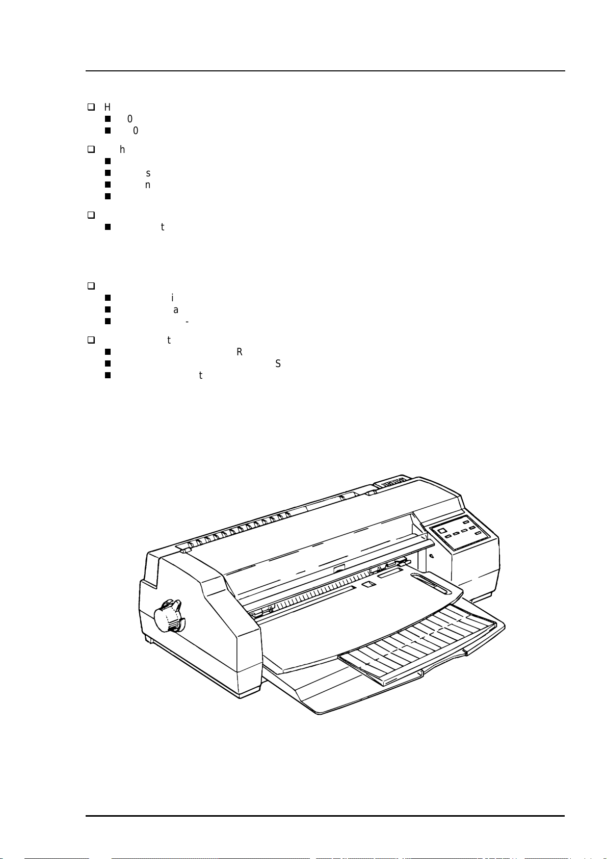
The EPSON Stylus COLOR 1520 is a business-use, high speed, and high-quality color ink jet printer.
The main features of this printer are:
High Speed Printing
400 cps for LQ mode
800 cps for draft mode
High print quality for color graphics
High Resolution :1440 (H) X 720 (V) dpi printing
Colors :Cyan, Magenta, Yellow, Black
Printing Method :Traditional and new micro weave printing
Smaller dot diameter for image improvement
Built-in auto sheet feeder with a wide availability and high capacity
This printer holds :Envelope up to A2 size portrait
:100 cut sheets (55 g/‡u)
:10 envelopes
:50 transparency films
:70 special paper
Built-in 2 interfaces and 1 optional interface card
Mac serial interface ( up to approximately 900 kbps)
Bi-directional parallel interface (IEEE1284 level 1 device)
Optional Type-B interface card
4 scalable fonts and 5 LQ fonts
Scalable fonts :Roman T, Sans Serif H, Roman, Sans Serif
LQ fonts :Roman, Sans Serif, Courier, Prestige, Script
Useful character tables :Italic, PC437, PC850, PC860, PC861, PC863, PC865, BRASCII,
Abicomp, Roman 8, ISO Latin 1
PC437 Greek, PC852, PC853, PC855, PC857, PC866, PC869,
MOZOAWIA, Code MJK, ISO 8559-7, Latin 1T, Bulgaria, PC774,
Estonia, ISO 8859-2, PC866 LAT
Rev. A
Figure 1-1. Exterior View of the EPSON Stylus COLOR 1520
1-1
Page 10

EPSON Stylus COLOR 1520
2
Model Description
C82305/C82306
C82307/C82308
C82310
C82313
C82315
C82314
C82312
C82331
C82345
C83602
C83603/C83604
C83605/C83606
C811**
S020108 Black ink cartridge
S020089 Color ink cartridge
S041059 / S041025 EPSON 360 dpi ink jet paper (A4)
S041060 EPSON 360 dpi ink jet paper (Letter)
S041065 EPSON 360 dpi ink jet paper (A3)
S041066 EPSON 360 dpi ink jet paper (Super A3/B)
S041061 / S041026 EPSON photo quality ink jet paper (A4)
S041062 EPSON photo quality ink jet paper (Letter)
S041067 EPSON photo quality ink jet paper (Legal)
S041068 EPSON photo quality ink jet paper (A3)
S041070 EPSON photo quality ink jet paper (B)
S041069 EPSON photo quality ink jet paper (Super A3/B)
S041054 EPSON photo quality ink jet card (A6)
S041121 EPSON photo quality ink jet card (5 X 8 inch)
S041122 EPSON photo quality ink jet card (8 X10 inch)
S041071 EPSON photo quality glossy film (A4)
S041072 EPSON photo quality glossy film (Letter)
S041107 EPSON photo quality glossy film (A6)
S041073 EPSON photo quality glossy film (A3)
S041075 EPSON photo quality glossy film (B)
S041074 EPSON photo quality glossy film (Super A3/B)
S041126 EPSON photo quality glossy paper (A4)
S041124 EPSON photo quality glossy paper (Letter)
S041125 EPSON photo quality glossy paper (A3)
S041123 EPSON photo quality glossy paper (A2)
S041063 EPSON ink jet transparencies (A4)
S041064 EPSON ink jet transparencies (Letter)
S041106 EPSON photo quality self adhesive sheet (A4)
S041103 EPSON 360 dpi ink jet banner paper
S041102 EPSON photo quality banner paper
S041*** EPSON ink jet canvas
S041*** EPSON back light film (A3)
S041*** EPSON back light film (A2)
Note) The asterisk is a substitute for the last digit of the product number,
which varies by country.
Table 1-1. Options and Consumables
Serial interface card
32 KB serial interface card
32 KB parallel interface card
32 KB EEE-488 interface card
Twinax interface card
Coax interface card
LocalTalk™ interface card
Ethernet interface card
Type-B Bidirectional parallel interface card
Parallel interface cable (shielded)
from D-SUB 25-pin (computer) to Amphenol 57
(printer)
Serial interface cable
from D-SUB 25-pin (computer) to D-SUB 25-pin
(printer)
Serial interface cable
from D-SUB 9-pin (computer) to D-SUB 25-pin
(printer)
Banner paper holder and cutting guide
1-
Rev. A
Page 11

3
1.2 Specification
This section provides detailed information on the EPSON Stylus COLOR 1520.
1.2.1 Printing Specifications
Printing method :On demand Ink jet
Nozzle configuration :Monochrome 128 nozzles (32 x 4 staggered)
:Color 64 nozzles each (magenta, cyan, yellow)
320/360 inch
32/360 inch
144/360 inch
#127#128
32/360 inch
#125#126
32/360 inch
#64
144/360 inch
#63
32/360 inch
144/360 inch
#64
32/360 inch
#63
Product Description
#64
#63
#2 #3#4#1
Black
Paper feed direction
#2
Cyan
#1
#2
Magenta
#1
Figure 1-2. Nozzle Configuration
Printing direction :Bi-directional with logic-seeking
Printing speed and Printable columns
Table 1-2. Print Speed and Printable Columns for Character Mode
Character Pitch Printable Columns LQ Speed Draft Speed
10 cpi (Pica) 136 400 cps 800 cps
12 cpi (Elite) 163 480 cps 960 cps
15 cpi 204 600 cps 1200 cps
17.1 cpi(Pica condensed) 233 684 cps 1378 cps
20 cpi(Elite dondensed) 272 800 cps 1600 cps
Table 1-3. Print Speed and Printable Columns for Raster Graphic Mode
Print Mode Printable Area Available Dot CR Speed
180 dpi X 180 dpi 11 inch 1980 40 ips
360 dpi X 360 dpi 11 inch 3960 20 ips
720 dpi X 720 dpi 11 inch 7920 20 ips
1440 dpi X 1440 dpi *
1
11 inch
7920 *
2
Note) 1: 1440 dpi X 720 dpi is available when using driver micro weave only.
2: 1440 dpi X 720 dpi can be printed by sending Following command sequence.
1. Set the print speed to 10 IPS.
2. Print 180 X 720 raster image.
3. Paper feed 31/720 inch.
4. Move 1/1440 inch print position.
5. Print 180 X 720 raster image.
6. Paper feed 31/720 inch.
Repeat the steps from 2 to 6.
#2
Yellow
10 ips
#1
Rev. A
1-
Page 12

EPSON Stylus COLOR 1520
4
1.2.2 Control codes
ESCP/2 and expanded raster graphics code
EPSON Remote command
IBMX24E emulation
1.2.3 Character tables
Legal and 14 international character sets
Standard version: 27 character tables
Italic table PC 437 (US, Standard Europe)
PC 850 (Multilingual) PC 860 (Portuguese)
PC 861 (IceLandic) PC 863 (Canadian-French)
PC 865 (Nordic) Abicomp
BRASCII Roman 8
ISO Latin 1 PC 437 (Greek)
PC 852 (East Europe) PC 853 (Turkish)
PC 855 (Cyrillic) PC 857 ( Turkish)
PC 866 (Russian) PC 869 (Greek)
MOZOAWIA (Poland) Code MJK (CSFR)
ISO 8559-7 (Latin, Greek) ISO Latin 1T (Turkish)
Bulgaria (Bulgaria) PC 774
Estonia ISO 8859-2 (ISO Latin 2)
PC 866 LAT
Typeface
Bit map LQ font EPSON Roman 10 cpi, 12 cpi, 15 cpi, Proportional
EPSON Sans Serif 10 cpi, 12 cpi, 15 cpi, Proportional
EPSON Courier 10 cpi, 12 cpi, 15 cpi,
EPSON Prestige 10 cpi, 12 cpi, 15 cpi,
EPSON Prestige 10 cpi, 12 cpi, 15 cpi
Scalable font EPSON Roman 10.5 pt., 8 pt. 32 pt. (every 2 pt.)
EPSON Sans Serif 10.5 pt., 8 pt. 32 pt. (every 2 pt.)
EPSON Courier 10.5 pt., 8 pt. 32 pt. (every 2 pt.)
EPSON Prestige 10.5 pt., 8 pt. 32 pt. (every 2 pt.)
EPSON Script 10.5 pt., 8 pt. 32 pt. (every 2 pt.)
Note) Each typeface has 4 variations:
Normal, Bold, Italic, and Bold Italic
An example of variations for Epson Roman is as follows:
Epson Roman normal
Epsom Roman bold
Epson Roman italic
Epson Roman bold italic
1-
Rev. A
Page 13

5
Combinations of Character tables and typefaces (font)
Table 1-14 shows the available combinations of character tables and Typefaces.
Table 1-4. Character Tables and Fonts
Bitmap Fonts Scalable Fonts Scalable Fonts
Character Tables
Italic
PC 860 (Portuguese))
PC 861 (IceLandic)
PC 863 (Canadian-French)
PC 865 (Nordic)
BRASCII
Abicomp
Roman 8
ISO Latin 1
Italic table
PC 437 (US Standard Europe)
PC 850 (Multilingual)
PC 437 (Greek)
PC 852 (East Europe)
PC 853 (Turkish)
PC 855 (Cyrillic)
PC 857 (Turkish)
PC 866 (Russian)
PC 869 (Greek)
MAZOWIA (Poland)
Code MJK (CSFR)
ISO 8859-7 (Latin/Greek)
ISO Latin 1T (Turkish)
Bulgaria (Bulgaria)
PC 774
Estonia
ISO 8859-2 (ISO Latin 2)
PC 866 LAT
EPSON Roman
EPSON Sans Serif
EPSON Courier
EPSON Prestige
EPSON Script
Supported Supported Supported
Supported Supported
EPSON Roman
EPSON Sans Serif
Product Description
EPSON Roman T
EPSON Sans Serif H
Not
Supported
1.2.4 Paper Feeding
Paper transport method :Friction feed with built-in auto sheet feeder (ASF)
Line spacing :1/6, 1/8 inch or programmable at 1/360 inch
Paper path :Cut-sheet ASF (Front entry)
:FF Rear tractor
Feed speed :66 ms / line (1 line = 1/6 inch)
88.9 mm / sec
3.5 inch / sec
Rev. A
1-
Page 14

EPSON Stylus COLOR 1520
6
1.2.5 Paper Specification
1.2.5.1 Cut Sheet
Table 1-5. Cut Sheet Size
Size Width Length
A4 210 mm (8.3”) 297 mm (11.7”)
Letter 215.9 mm (8.5”) 279.4 mm (11.0”)
B5 182 mm (7.2”) 257 mm (10.1”)
Legal 215.4 mm (8.5”) 355.6 mm (14.3”)
B4 257 mm (10.1”) 364 mm (14.0”)
A3 297 mm (11.7”) 420 mm (16.5”)
Ledger 279.4mm (11.0”) 431.8 mm (17.0”)
A3 wide 329 mm (13.0”) 483 mm (19.0”)
A2 420 mm (16.5”) 594 mm (23.4”)
US-C 431.8 mm (17.0”) 558.8 mm (22.0”)
B5 (ISO) 176 mm (6.9”) 250 mm (9.8”)
B4 (ISO) 250 mm (9.8”) 353 mm (13.9)”
Paper Thickness :0.065 mm (0.0025”) to 0.11 mm (0.004”)
Paper Weight :64 g/ m
:52 g/ m
Quality :Exclusive paper *
Note) 1. A2 portrait and US-C portrait are used by manual insertion only.
2. Be sure to use the designated side of exclusive paper.
2
(17 lb.) to 90 g/ m2 (24 lb.) (ASF)
2
(14 lb.) to 90 g/ m2 (24 lb.) (Manual insertion)
2
, Bond paper, PPC
1.2.5.2 Transparency
Table 1-6. Transparency Size
Size Width Length
A4 210 mm (8.3”) 297 mm (11.7”)
Letter 215.9 mm (8.5”) 279.4 mm (11.0”)
Paper thickness :0.075 mm (0.003”) to 0.085 mm (0.0033”)
Note) Transparency printing is only available at normal temperatures.
Transparency paper must be printed on the designated side.
1.2.5.3 Envelope
Table 1-7. Envelope Size
Size Width Length
No.10 241.3 mm (9 1/2”) 104.8 mm (4 1/8”)
DL 220 mm (8.7”) 110 mm (4.3)
C5 229 mm (9”) 162 mm (6.4)
Paper Thickness :0.16 mm (0.006”) to 0.52 mm (0.02”)
Paper Weight :45 g/m
Quality :Bond paper, Plain paper, Air mail
Note) Envelope printing is only available at normal temperatures.
Place the longer side of the envelope horizontally when setting.
2
(12 lb.) to 90 g/ m2 (24 lb.)
1.2.5.4 Index Card
Table 1-8. Index Card Size
Size Width Length
A6 index card 105 mm (4.1”) 148 mm (5.82”)
Card Thickness :0.23 mm (0.0091”)
1-
Rev. A
Page 15

Product Description
7
1.2.5.5 Labels (Cut Sheet)
Table 1-9. Label Size
Size Width Length
A4 210 mm (8.3”) 297 mm (11.7”)
Letter 216 mm(8.5”) 279 mm (11.0”)
Paper thickness :0.2 mm (0.0079”) including base sheet
Quality :Page printer label
Note) Label must be printed at normal room temperature.
1.2.5.6 Continuous Paper
Paper size :Paper width 101.6 mm (4”) to 406.4 mm (16”)
:Folding length 101.6 mm (4”)
Paper thickness :0.065 mm (0.0026”) to 0.11 mm (0.0043”)
Paper Weight :52 g/ m
2
(14 lb.) to 82 g/ m2 (22 lb.)
1.2.5.7 Labels (Continuous)
Paper size
Base sheet :Paper width 101.6 mm (4”) to 406.4 mm (16”)
:Folding length 101.6 mm (4”)
Label :Width 63.5 mm (2.5”)
:Length 23.9 mm (0.94”)
Paper thickness :0.2 mm (0.0079”) or less including base sheet
:0.12 mm (0.0047”) or less without base sheet
Quality :Plain paper
Note) Label (continuous) must be printed under normal room temperatures.
1.2.5.8 Banner
Size :Width :210 mm (8.32) to 432 mm (17.0”)
:Length :5.0 m or less (196.9”)
Thickness :0.08 mm (0.0031”) to 0.1 mm (0.0039”)
Weight :64 g/m
Quality :Plain paper
2
(17 lb.) to 82 g/ m2 (22 lb.)
Rev. A
1-
Page 16

EPSON Stylus COLOR 1520
8
1.2.6 Printable Area
Cut Sheet
PW
LM RM
TM
Printable Area
PL
BM
Figure 1-3. Printable Area for Cut Sheet
Table 1-10. Minimum Margins for Different Cut Sheet Sizes
PW LM (Left Margin) RM (Right Margin) TM BM
(Paper
Width)
A4
297 mm
Set to right
edge
3 mm
(0.12”)
Set to left
edge
3 mm
(0.12”)
Set to right
edge
3 mm
(0.12”)
Set to left
edge
3 mm
(0.12”)
(Top Margin) (Bottom
3 mm
(0.12”)
(11.87”)
Legal (L)
356 mm
3 mm
(0.12”)
5 mm
(0.20”)
5mm
(0.20”)
3 mm
(0.12”)
3 mm
(0.12”)
(14.0”)
B4 (L)
364mm
3 mm
(0.12”)
16 mm
(0.51”)
16 mm
(0.51”)
3 mm
(0.12”)
3 mm
(0.12”)
(14.3”)
A3 (L)
420 mm
13 mm
(0.51”)
25 mm
(0.98”)
62 mm
(2.32”)
50 mm
(1.85”)
3 mm
(0.12”)
(16.5”)
Ledger (L)
432 mm
25 mm
(0.98”)
25 mm
(0.98”)
62 mm
(2.32”)
62 mm
(2.32”)
3 mm
(0.12”)
(17.0”)
Note) 1. (L) : When the paper is placed in landscape orientation.
2. Printable are of label (cut sheet) is as same as cut sheet.
Margin)
14 mm
(0.54”)
14 mm
(0.54”)
14 mm
(0.54”)
14 mm
(0.54”)
14 mm
(0.54”)
1-
Rev. A
Page 17

9
Envelope
Product Description
LM
LM (Left Margin)
(minimum)
3 mm
(0.12”)
Printable area
Figure 1-4. Printable Area for Envelopes
Table 1-11. Minimum Margin for Envelope
RM (Right Margin)
(minimum)
3 mm
(0.12”)
TM (Top Margin)
(minimum)
3 mm
(0.12”)
RM
TM
BM
BM
(Bottom Margin)
(minimum)
14 mm
(0.55”)
Rev. A
1-
Page 18

EPSON Stylus COLOR 1520
0
Continuous Paper
Note) 1. Printable area of label (continuous) is as same as for continuous paper.
2. Base sheet of label (continuous) is not within the printing area.
More than
3 mm (0.12 ")
Perforation
Perforation
More than
13 mm (0.51") *1
Printable are 1
Printable area 2
Printable are 1
Printable area 2
Printable area 2
Printable are 1
More than
13 mm (0.51") *1
More than
12.5 mm (0.49")
More than
9 mm (0.35")
More than
9 mm (0.35")
More than
9 mm (0.35")
More than
9 mm (0.35")
More than
14 mm (0.55")
*1 : When the paper width is more than 406.4 mm (16"), this width is more than
38 mm (1.50").
Printable area 2
Printable are 1
Perforation
Printable Area 1: Paper feed pitch is not guaranteed in this area.
Printable Area 2: Paper feed pitch is guaranteed in this area.
Perforation
Perforation
Figure 1-5. Printable Area for Continuous Paper
More than
134 mm (5.28")
1-1
Rev. A
Page 19

Product Description
1.2.7 Adjust Lever
The adjust lever , located at the left and upper side of the printer , is used to adjust the gap between the
paper and platen. The adjust lever must be set to the proper position the paper type in order to prevent
the paper from smudging.
Table 1-12. Adjust Lever Position
Paper
Type
Cut sheet
Transparency
Continuous paper
Index card
Envelopes Near side (+) + 0.7 mm
Lever
Position
Far side (0) 0 mm
Platen Gap Adjustment
Value
Adjust lever
+
0
Figure 1-6. Adjust Lever Settings
Rev. A
1-11
Page 20

EPSON Stylus COLOR 1520
2
1.2.8 Ink Specification
1.2.8.1 Black ink cartridge
Table 1-13. Black Ink Cartridge Specifications
Black Ink Cartridge
Type Exclusive ink cartridge
Color Black
Print capacity 900 pages / A4 (ISO/IEC10561 Letter Pattern at 360 dpi)
Ink life 2 years from indicated production date
Storage Temperature
At storage : -20 •• to 40 ••
At packing storage : -30 •• to 40 ••
At transit (Packed) : -30 •• to 60 ••
Dimension 30 mm (W) X 58 mm (D) X 38.5 mm (H)
(1.22” X 2.36” X 1.57”)
*1 : Within a month at 40 ••
*2 : Within 120 hours at 60 •• for more than 120 hours.
1.2.8.2 Color ink cartridge
Table 1-14. Color Ink Cartridge Specifications
Color Ink Cartridge
Type Exclusive ink cartridge
Color Magenta, Cyan, Yellow
Print capacity 300 pages A4 (at 360 dpi, 5 % duty each color)
Ink life 2 years from indicated production date
Storage Temperature
Dimension 42.9 mm (W) X 56.5 mm (D) X 38.5 mm (H)
*1 : Within a month at 40 •• for more than a month.
*2 : Within 120 hours at 60 •• for more than 120 hours.
Note)
1. The cartridge must not be refilled. Only ink cartridge is prepared for article of consumption.
2. Do not used the cartridge that has exceeded the ink life.
3. When the ink is frozen under -4
before using.
At storage : -20 •• to 40 ••
At packing storage : -30 •• to 40 ••
At transit (Packed) : -30 •• to 60 ••
(1.75”X 2.30” X 1.57”)
C, leave it for more than 3 hours at the room temperature to defrost
* 1
* 1
* 1 *2
* 1
* 1
* 1 *2
1.2.9 Input Data Buffer
Input data buffer :64 Kbytes
1-1
Rev. A
Page 21

3
1.2.10 Electric Specifications
120 V version
Rated voltage :AC 120 V
Input voltage range :AC 103.5 to 132 V
Rated frequency renege :50 to 60 Hz
Input frequency range :49.5 to 60.5 Hz
Rated current :0.7 A (maximum)
Power consumption :Approximately 21 W (ISO/IEC 10561 Letter pattern)
Conforms to Energy Star program
Insulation resistance :10 M ohms min. (Between AC line and chassis, DC 500 V))
Dielectric strength :AC 1,000 V rms. (1 minute) or AC 1,200 V rms. (1 second)
(Between AC line and chassis)
220 - 240V version
Rated voltage :AC 220 to 240 V
Input voltage range :AC 198 to 264 V
Rated frequency renege :50 to 60 Hz
Input frequency range :49.5 to 60.5 Hz
Rated current :0.4 A (maximum)
Power consumption :Approximately 21 W (ISO/IEC 10561 Letter pattern)
Conforms to Energy Star program
Insulation resistance :10 M ohms min. (Between AC line and chassis, DC 500 V)
Dielectric strength :AC 1,500 Vrms. (1 minute) (Between AC line and chassis)
Product Description
1.2.11 Environmental Conditions
Temperature
Operating*
Non operating*
Humidity
Operating*
Non operating*
Resistance to vibration
Operating :0.15 G
Non-operating*
Resistance to shock
Operating :1 G within 1 ms
Non-operating*
*1 :Refer to the table below for guaranteed range.
*2 :In shipment container.
*3 :Without condensation
1
1
*
2
3
3
2
*
2
2
Humidity (%)
90
80
:10•• to 35••
:-20•• to 40•• ( 1 month at 40••)
-20•• to 60•• (120 hours at 60••)
:20% to 80% RH (without condensation)
:5% to 85% RH (without condensation)
:0.50 G
:2 G within 2 ms
70
60
50
40
30
20
C
10 20
(50 H)
C
27
(80 H)
30
C
C
35
C
(95 H)
Temperature ( )
40
C
C
Figure 1-7. Environmental Conditions
Rev. A
1-1
Page 22

EPSON Stylus COLOR 1520
4
1.2.12 Reliability
Total print volume :75,000 pages (A4/Lletter)
Print head life :2,000 million dots /nozzle
1.2.13 Safety Approvals
120 V version
Safety standards :UL1950 with D3
CSA22.2 No. 950 with D3
EMI :FCC part15 subpart B class B
220 - 240 V version
Safety standards :EN 60950 (TÜV, NEMKO)
EMI :EN 55022 (CISPR Pub.22) class B
:AS/NZS 3548 class B)
1.2.14 CE Marking
220 - 240 V version
Low Voltage Directive 73/23/EEC :EN60950
EMC Directive 89/336/EEC :EN55022 class B
EN61000-3-2
EN61000-3-3
EN50082-1
IEC801-2
IEC801-3
IEC801-4
1.2.15 Acoustic Noise
Noise level :Approximately 45 dB (A) (According to ISO 7779)
1-1
Rev. A
Page 23
Product Description
5
1.3 Interfaces
1.3.1 Parallel Interface
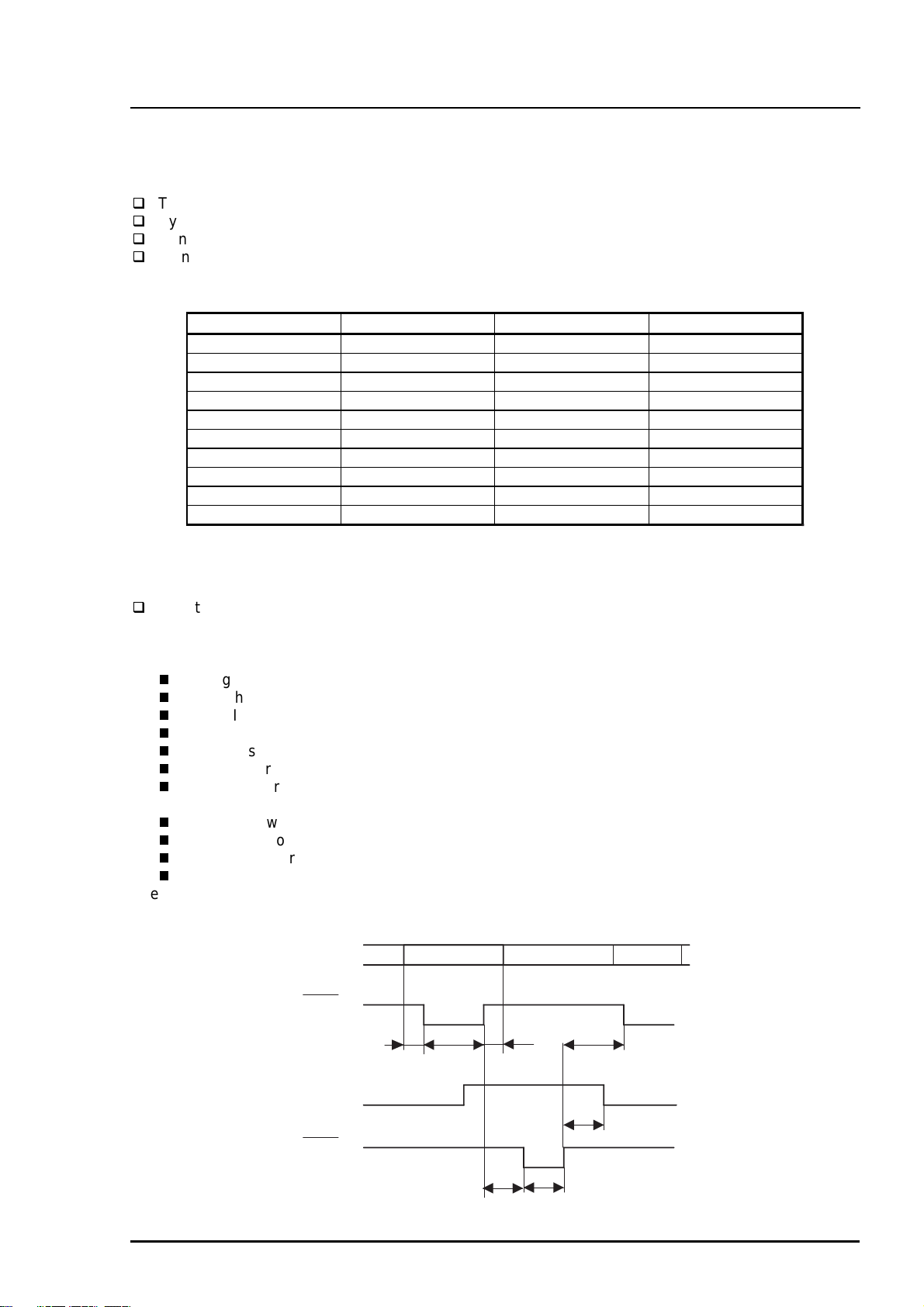
1.3.1.1 Forward Channel Specifications
Transmission mode :8 bit parallel , IEEE-P1284 compatibility mode
Synchronization :/STROBE pulse
Handshaking :BUSY and /ACKNLG signal
Signal level :TTL compatible level (IEEE-P1284 Level 1 device)
Table 1-15. Signal level of TTL Compatible (IEEE-1284 level 1 device)
Parameter Minimum Maximum Condition
VOH* - 5.5 V
VOL* -0.5 V -
IOH* - 0.32 mA VOH = 2.4 V
IOL* - 12 mA VOL = 0.4 V
CO - 50 pf
VIH - 2.0 V
VIL 0.8 V -
IIH - 0.32 mA VIH = 2.0 V
IIL - 12 mA VIL = 0.8 V
CI - 60 pf
Note) * : A low logic level on the Logic H signal is as follows:
2.0 V or less when the printer is powered off.
3.0 V or more when the printer is powered on.
The receiver shall provide an impedance equivalent to 7.5 K ohm top ground.
Adaptable connector :57-30360 (Amphenol) or equivalent
The BUSY signal is set high before setting either /ERROR low or PE high and held high until all these
signals return to the inactive state.
The BUSY signal is at high level in the following cases:
During data entry (see Figure 1-8. Data Transmission Timing below.)
When the input data buffer is full
While /INIT signal is at low level or during hardware initialization
During a printer error condition (See /ERROR signal)
During test printing
When the printer is in default setting mode
When the parallel interface is not selected
The ERROR signal is at low level when one of the following errors has occurred:
Printer hardware error (fatal error)
Paper-out error
Paper-jam error
Ink-out error
The PE signal is high level during paper-out error.
DATA
STORBE
0.5 us (min.)
BUSY
ACKNLG
DATA (n)
0.5 us (min.)
0.5 us (min.)
0 (min.)
DATA (n+1)
0 (min.)
0 (min.)
5 us (type.)
Figure 1-8. Data Transmission Timing
Rev. A
1-1
Page 24
EPSON Stylus COLOR 1520
6
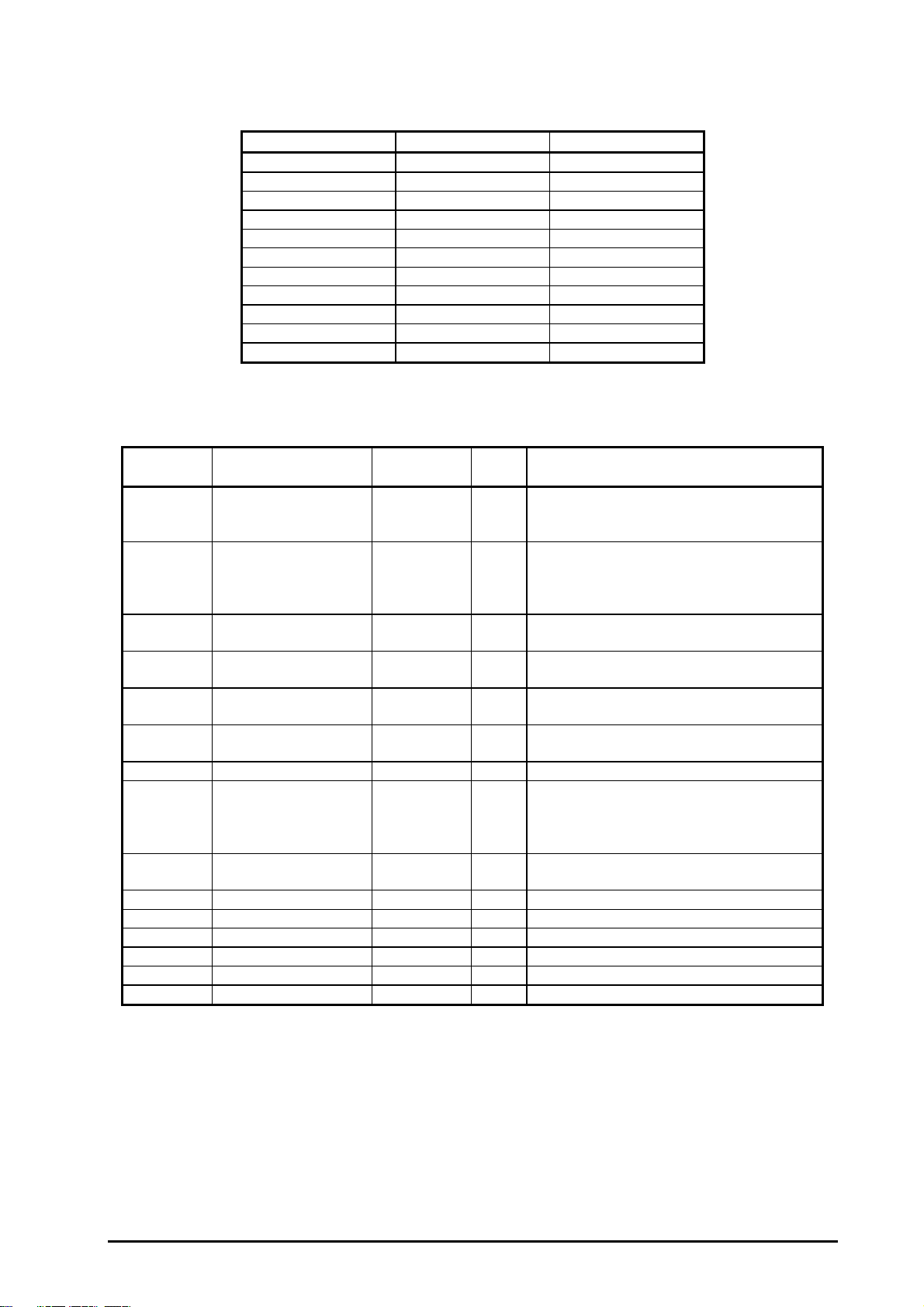
Table 1-16 shows the connector pin assignment and signals for forward channel of the parallel interface.
Table 1-16. Data Transmission Timing
Parameter Minimum Maximum
tsetup 500 ns -
thold 500 ns -
tstb 500 ns -
tready 0 -
tbusy - 500 ns
tt-out* - 120 ns
tt-in** - 200 ns
treply - -
tack 500 ns 10 us
tnbusy 0 -
tnext 0 -
Note) * : Rises and falls in time of every output signals.
**: Rises and falls in time of every input signal.
Table 1-17. Connector Pin Assignments and Signals (Forward Channel)
Pin No. Signal Name Return
GND Pin
1 /STROBE 19 I
2-9 DATA 0-9 20-27 I
10 /ACKNLG 28 O This signal is a negative pulse indicating
11 BUSY 29 O When this signal is at high level, the
12 PE 28 O When this sign is at high level, the paper
13 SLCT 28 O Always at high level when the printer is
14 /AFXT 30 I Not used.
31 /INIT 30 I The falling edge of a negative pulse or a
32 /ERROR 29 O When the printer detects an error, this
36 /SLIN 30 I Not used.
18 Logic H - O Pulled up to +5V via 3.9 K ohm resistor.
35 +5V - O Pulled up to +5V via 3.3 K ohm resistor.
17 Chassis GND - - Chassis ground.
16,33,19-30 GND - - Signal ground.
15,34 NC - - Not connected.
I/O Description
The strobe pulse. Read-in of data is
performed at the falling edge of this
pulse.
The data 0 to data 7 signals represent
data bits 0 to 7, respectively. Each signal
is at high level when data is logical 1 and
low level when data is logical 0.
that the printer can again accept data.
printer is not ready to accept data.
empty status is detected.
powered on.
low signal on this line causes the printer
to initialize. Minimum 50 us pulse is
necessary.
signal goes low.
Note) 1. */* at the beginning of a signal means active low.
2. The I/O column indicates the diction of the signal as viewed form the printer.
1-1
Rev. A
Page 25

Product Description
7
1.3.1.2 Reverse Channel Specifications
Transmission mode :IEEE-1284 nibble mode
Adaptable connector :Same as for the forward channel
Synchronization :Refer to the IEEE-1284 specification
Handshaking :Refer to the IEEE-1284 specification
Data transmission timing :Refer to the IEEE-1284 specification
Signal level :IEEE-1284 level 1 device
See the forward channel specification.
Table 1-18 shows the connector pin assignment and signals for reverse channel of the parallel interface.
Table 1-18. Connector Pin Assignment and Signals (Reverse Channel)
Pin No. Signal Name Return
GND Pin
1 HostClk 19 I Clock signal from the host computer.
2-9 DATA 0-7 20-27 I These signals represent parallel data
10 PtrClk 28 O Clock signal from the printer
11 PtrBusy /
Data bits 3,7
12 AckDatareq /
AckData Bits 2,6
13 Xflag/Data bit 1,5 28 O X flag signal.
14 HostBusy 30 I Busy signal from the host computer
31 /INIT 30 I Not used
32 /Data Avail /
Data bits 0,4
36 1284-Active 30 I 1284 active signal.
18 Logic-H - O Pulled up to +5V via 3.9 K ohm resistor.
35 +5V - O Pulled up to +5V via 3.3 K ohm resistor.
17 Chassis GND - - Chassis ground for the printer.
16,33,19-30 GND - - Signalground.
15,34 NC - - Not connected.
29 O Busy signal from the printer.
28 O Acknowledge request signal.
29 O Data available signal.
I/O Description
information on bits 2 to 9.Each signal is
High when the data is logical 1 and low
when the data is logical 0.
Data bit 3 or 7 in reverse channel.
Data bit 2 or 6 in reverse channel.
Data bit 1 or 5 in reverse channel.
Data bit 0 or 4 in reverse channel.
Note) The symbol */* at the beginning of a signal means active low.
Extensibility Request
The printer responds affirmatively when the extensibility request values are 00H or 04H, as follows:
00H :Request Nibble Mode Reverse Channel Transfer.
04H :Request Device ID;
Return Data Using Nibble Mode Rev Channel Transfer.
Device ID
The printer sends following device ID string when it is requested.
[00H] [xxH]
MFG :EPSON;
CMD :ESCP2E, PRPXL;
MDL :Stylus COLOR 1520;
CLS :PRINTER
Note) [00H] denotes a hexadecimal values of zero.
Rev. A
1-1
Page 26

EPSON Stylus COLOR 1520
8
1.3.2 Mac Serial Interface
1.3.2.1 Serial Interface Specifications
Standard :RS-423 compliance
Synchronization :Synchronous
Bit rate :Approximately 900 Kbps, 1.8 Mbps
Word format :Start bit 1 bit
:Data bit 8 bit
:Parity bit No parity bit
:Stop bit 1 bit
Handshaking :X-ON/XOFF, DTR protocol
Adaptable connector :8-pin mini circular connector
Recommended I/F cable :Apple System Peripheral-8 cable
Table 1-19. Connector Pin Assignment for Serial Interface
Pin No. Signal Name I/O Function Description
1 SCLK O Synchronous clock
2 CTS I Clear to send
3 TxD- O Transmit data 4 S.G. I Signal Ground
5 RxD- I Receive data 6 TxD+ O Balanced Transmit +
7 DTR O Data terminal ready
8 RxD+ I Balanced Receive +
8
7
5
2
Figure 1-9.
Serial Interface Connector Pin Assignment
Table 1-20. X-ON/X-OFF, DTR Protocol
State Buffer space X-ON/X-OFF DTR
Busy Less than 1024 bytes Send X-OFF code Off
Ready More than 2048 bytes Send X-ON code On
6
34
1
1-1
Rev. A
Page 27

Product Description
9
1.3.3 Optional Interface
The EPSON Stylus COLOR 1520 supports an optional Type-B interface (Level 2) with the following
characteristics.
Reply message
When ESC/P2 is selected:
Main type :MTP48p, PW136cl10cpi, PRG(W0xxxx)rev, AP800ma, SPD0fast
Product name :Stylus COLOR 1520
Emulation type :ESCPL2-00
Entity type :EPSONLQ2
When X24E is selected:
Main type :MTP48p, PW136cl10cpi, PRG(W0xxxx)rev, AP800ma, SPD0fast
Product name :Stylus COLOR 1520
Emulation type :PRPXL24-00
Entity type :EPSONPRPXL24
Table 1-21.Reply for Option Command
Option command No. command name Reply-A Reply-B
00h No Operation Accept None
01h Start Hard Ware Reset Accept Excute OK
02h Start Soft Ware Reset Reject
03h Send Main System Type Accept
04h Send Name Data Reject
05h Inquire Name Data Accept
06h Send Product Name Accept
07h Send Soft Ware Emulation Type Accept
08h Complete Buffered Data Accept Check Condition
09h Stop Procedure Reject Execute OK
0Ah Return Buffered Data Reject
0Bh Send Entity Type Accept
0Ch Send Status Accept
0Dh Quit Procedure Reject
0Eh Inquire ASCII Message Reject
0Fh Send ASCII Message Accept None
10h - 13h Unknown None
14h Inquire Emergency Message Accept Execute OK
15h Send Emergency message Accept
16h - 1Fh Unknown None
20h - FFh Reserved None
Table 1-22. Supported Main Command and Sending Timing
Main Command No. Command name Sending Timing
01h Start Software Reset
04h Send Name Data
07h Inquire Software Emulation Name
0Eh Inquire ASCII Message
14h Inquire Emergency Reply
15h Send Emergency Message
Emergency Command
0X00 :Get device ID
0X01 :Get all status
Sending BDC-ST through DBIN register
When State-Reply is set “ON”, by ST from Type-B I/F, sending BDC-ST through DBIN register is
started. When State-Reply is started, “Start” and “End” of BDC-ST characters are announced by
sending the Main command 0Eh.
Rev. A
/INIT signal on the std. parallel I/F
Type-B I/F option command : 01h
Cold Start
Type-B I/F command : 05h
Changing software Emulation Type
Writing to DBIN register
Reply for Emergency command
Receive Emergency Command
1-1
Page 28

EPSON Stylus COLOR 1520
0
1.3.4 Prevention Hosts from Data Transfer Time-out
Generally, hosts abandon data transfer to peripherals when a peripheral is in the busy state for dozens of
seconds continuously. To prevent hosts from this kind of time-out, the printer receives data very slowly,
several bytes par minute, even the printer is in busy state. This slowdown starts when the rest of input
buffer drops under several hundreds of bytes. Finally, the printer is in the busy state continuously when
the input buffer is full.
1.3.5 Interface Selection
The EPSON Stylus COLOR 1520 has three types of interface available :Parallel, Serial, and optional
interfaces. Each interface can be selected manually or automatically. Both modes are selected thorough
the default setting mode.
Manual selection
The interface selected through the default setting mode always prints out data from the host.
Automatic selection
When the printer is in this mode, the printer is initialized to the idle state when it is turned on. Then
the interface that receives data first will print. When the host stops data transfer and the printer is in
the stand-by state for the specific time, the printer returns to the idle state. As long as the host sends
data or the printer interface is buy state, the selected interface remains active.
Interface State and Interface Selection
When the parallel interface is not selected, the interface goes into the busy state. When the serial
interface is not selected, the interface sets the DTR signal MARK. When the printer is initialized or
returned to the idle state, the parallel interface goes into the ready state and the serial interface sets the
DTR signal SPACE. Caution that the interrupt signal such as the /INIT signal on the parallel interface is
not effective while that interface is not selected.
1.3.6 Printer language and Control Codes
Printer languages and control codes :ESC/PC
:IBM X24E
:EPSON Remote
1-2
Rev. A
Page 29

Product Description
1.4 Operation
This section describes the controls, settings and adjustment used to operate the EPSON Stylus COLOR
1520.
1.4.1 Control Panel
The control panel of this printer consists of 6 non-lock push switches, 1 lock type push switch, and 6 LED
indicators for easy operation of the various printer functions. Refer to
Figure 1-10 for button and LEDs descriptions and how they are arranged.
(1)
(2)
(3)
(4)
(5)
(6)
Indicators
(1) Cover Open
(2) Operate
(3) Ink Out (Black)
(4) Ink Out (Color)
(5) Paper Out
(6) Pause
5sec
Reset
Operate
Cover Open
Micro Feed
Ink Out
Ink Out
Paper Out
Micro Feed
Figure 1-10. Control Panel Appearance
Alt
LF/FF
Cleaning
Load/Eject
Cleaning
Rev. A
1-21
Page 30

EPSON Stylus COLOR 1520
2
Panel Functions :The function of each button is described below.
Power
Function :Turns the printer off or on *
Available condition :Always
1
.
Load/Eject
LF/FF
Pause
Micro-adjust
Micro-adjust
2
*
Cleaning (Black)
Function :Loads and ejects the paper.
Available condition :Pause/Stand-by
Function :Feeds one line or page.
Available conditions :Pause / Stand-by
Function :Alternates the printer state between printing and non-
printing.
Available conditions :Pause / Stand-by
Function : Pressing this button for 3 seconds resets the printer.
Available condition :Pause / Stand-by
Function :Feeds paper forward and is used to execute TOF
adjustment *
2
and Tear off adjustment *3.
Available conditions :Pause / Stand-by
Function :Feeds paper backward and performs TOF adjustment
and Tear off adjustment *3.
Available conditions :Pause / Stand-by
Function :Executes the black ink cartridge cleaning.
Available condition :Pause
Cleaning (Color)
Function :Executes the color ink cartridges cleaning.
Available condition :Pause
Alt
Function :Enters ink cartridge change mode. Pressing this button
for 3 seconds moves the ink cartridge to the position to
be replaced.
Available conditions :Pause / Ink out
Note)
1. Before the printer power is off, the printer executes the capping function.
2. When the micro adjust is performed at the TOF (Top Of Form position) for the ASF manual and
tractor feed, the new setting is stored in the corresponding address in the EEPROM.
3. When the micro adjust is performed at the tear off position, the new setting is stored in the
corresponding address in the EEPROM
CAUTION
The power switch is connected to the secondary side of the electrical circuit. Since it has a delay
circuit, voltage is still applied for the specified period of time after the printer power is off.
As long as the printer is plugged in, voltage is applied to the primary side of the electrical circuit.
Therefore be sure to unplug the printer before servicing or replacing the interface.
1-2
Rev. A
Page 31

Product Description
3
1.4.2 Panel Functions at Power On
This printer also enters various functions by turning on the printer while holding down a button
( buttons). Each combination and corresponding function is described in the table below.
Table 1-23. Panel Functions at Powered On
Switch *
(while turning on the printer)
Micro adjust
Pause Enters printer adjustment mode. (See Section 1.4.5.)
Load /Eject Enters LQ self-test printing mode.
LF/FF Enters draft self-test printing mode.
LF/FF + Load/Eject Enters hex-dump mode.
Alt + LF/FF + Load/Eject
+ Micro adjust
1
Enters default setting mode. (See Section 1.4.4.)
Enters EEPROM and Timer IC reset *
Function
2
mode.
Note) 1.”+” means to press one button while holding down the other button(s).
2.EEPROM and Timer IC must be reset only by qualified service personnel.
CAUTION
When performing EEPROM reset operation, waste ink drain pads must be replaced. Therefore
EEPROM reset is to be performed by a qualified service person only. (See Chapter 3.)
Rev. A
1-2
Page 32

EPSON Stylus COLOR 1520
4
1.4.3 Printer Condition and Panel Status
This printer has several printer conditions that are indicated by the LEDs on the control panel When any of
the errors listed below occurs, the printer indicates an error condition and the /ERROR signal goes “Low”
and Busy signal goes “High” to stop data transfer. This condition automatically puts the printer into
“Pause” status.
The carriage moves abnormally. (Fatal error)
Paper out or Paper jam condition is detected.
The PG for the paper currently loaded is inaccurate.
No ink cartridge or Ink end condition is detected.
Maintenance is required.
Table 1-24. Printer Condition and Panel Status
Indicators
Printer status Power Cover Open Ink out
(black)
Power on On
Cover open
Paper out
Paper jam
No ink cartridge or
ink end (black)
Ink level low (black)
No ink cartridge or
ink end (color)
Ink level low (color)
Enter EEPROM and
Timer IC reset
Maintenance request Blinks Blinks Blinks Blinks Blinks Blinks
Fatal error
Lever error
Capping function in
the power off
Data exit Blinks
In the sequence of
ink cartridge change
mode
Default setting mode Blinks
On
1 second
Blinks
On
On
1 second
Blinks
On
Blinks
On
1 second
Note)
1. “-” means no effect.
2. Fatal error is cleared by turning off and back on the printer or by inputting the /INIT signal after the
problem is solved.
3. Maintenance is required when the wasted ink drain pads are filled with the wasted ink to the specified
limit. On this condition servicing is needed. To clear the condition, perform EEPROM reset operation.
(See Section 1.4.2 “Panel function at power on”) Refer to Chapter 2 or Chapter 3.
Ink out
(color)
On
Blinks
On
1 second
Paper Out Pause
On
Blinks
On
1 second
Blinks Blinks
On
1 second
Blinks
Blinks
1-2
Rev. B
Page 33

Product Description
5
1.4.4 Cover Open Sensor Operation
The cover open sensor equipped with this printer controls the carriage movement which has a possibility
to hurt the user. The sensor performs followings:
The printer cover opens during printing:
The CR returns to the home position slowly after executing printing for the current pass. The cover
open LED lights up and the printer goes into the stand-by status.
To recover, close the cover and press the pause button to continue to print. The cover open LED
goes off with the recovery.
The printer cover opens during cleaning:
The printer completes the cleaning sequence. If the cover is still open after the cleaning, the cover
open LED lights up and the printer goes into the stand-by status.
To recover, close the cover and press the pause button to continue to print. The cover open LED
goes off with the recovery.
The printer cover opens While the printer is in the stand-by status:
The cover open LED lights up and the printer stops functioning. *
To recover, close the printer cover.
*1 :The interface is in the Busy status and the switches on the control panel are effective.
1
1.4.5 Default Setting
This printer has user-selectable default settings to which it refers at initialization. This section describes
setting method and setting menus.
1.4.5.1 Setting Method
See the flow chart in Page 1-26 for the default setting method.
CAUTION
Be sure to turn off the printer off once after the default setting operation is executed, since
adjustment values are not stored in the EEPROM until the printer is turned off.
The latest adjustment values set before power-off are stored in the EEPROM.
Rev. A
1-2
Page 34

EPSON Stylus COLOR 1520
6
Start
Press the "Micro Adjust " button,
and
The printer prints "Usage of this
mode" and firmware version number.
1.Move through the languages listed
in "Usage of this mode" by
pressing the "Alt " button.
2.Select the language by pressing
the Pause button.
The printer prints the current
setting and "Usage of this mode"
in the selected language on the
currently loaded paper.
the printer on.
turn
Change the settings?
NO
YES
1. Select the menu by pressing the
"Alt" button.
2. Press the "Pause" button.
LED indicators indicate the values for
the selected menu.
1. Scroll the values by pressing the "Load/Eject"
button.
2. Select the value by pressing the "Alt" button.
3. Press the "Pause" button.
The printer memorizes the setting value and
changes the indication to the main menu.
YES
More change?
NO
Turn the printer off to save the new settings into the EEPROM.
Figure 1-11. Default Setting Flowchart
1-2
Rev. B
Page 35

7
1.4.5.2 Setting Menus
The default setting menus are described in the table below.
Table 1-25. Default Setting Menu
Menu Setting *
Print direction*
Font
2
/ Bi-d / Uni-D
Auto
Roman / Sans Serif /
Courier
/ Prestige / Script/
Roman T / Sans Serif H / Draft
Pitch
I/F mode
Auto I/F wait mode
Software
Auto CR (IBM mode only)
AGM (IBM mode only)
Character tables
Standard version
10 cpi
Auto
10 seconds
ESC/P2
On /
On /
Italic
PC 437
/ 12 cpi / 15 cpi / 17.1 cpi / 20 cpi / Proportional
/ Parallel / Mac Serial / Option
/ 30 seconds
/ IBM X24E
Off
Off
, PC 850
PC 860, PC 863
PC 865, PC 861
BRASCII, Abicomp
Roman 8, ISO Latin 1
PC 437 (Greek), PC 853
PC 855, PC 852
PC 857, PC 866
PC 869, MOZOAWIA
Code MJK, ISO 8559-7
ISO Latin 1T, Bulgaria
PC 774, Estonia
ISO 8859-2, PC 866 LAT
International character set
for Italic table
Italic USA
Italic Germany, Italic U.K
, Italic France
Italic Denmark, Italic Sweden
Italic Italy, Italic Spain 1
Auto line feed
On /
Off
Network I/F mode This mode is for network environment.
: Used in usual environment
Off
On: Used in network environment
0 slash 0 / 0 with slash
Page length 11 inch / 12 inch / 8.5 inch / 70/6 inch / other
Skip over perforation
Auto tear off
Banner mode *
3
Parallel I/F transfer rate
On /
/ Off
On
On /
Fast
Off
Off
/ Normal
Note) 1. Underlined parameters in bold letter are factory default settings.
2. Refer to Table 1-26 and Table-27.
3. Refer to Table 1-28..
1
Product Description
Rev. A
1-2
Page 36

EPSON Stylus COLOR 1520
8
Table 1-26. Print Direction Mode Characteristics
Black and White Printing YMCK Printing (color)
Auto
Bi-D
Uni-D
Throughput and quality is better.
Throughput is the best.
Print quality may be down.
Throughput is worse.
Print quality is the best.
Table 1-27. Printing Direction and ESC U Command
Throughput is better.
Color quality with special paper is
worse.
(Color correction depends on the print
direction.)
Throughput is the best.
Color quality with special paper is
worse.
(Color correction depends on the print
direction.)
Throughput is worse.
Color quality is the best.
Character Mode
(for DOS)
ESC U 0 Auto Bi-D
Auto ESC U 1 Auto Uni-D
ESC U 2 Auto Auto
ESC U 0 Bi-D Bi-D
Default Bi-D ESC U 1 Uni-D Uni-D
Setting Mode ESC U 2 Auto Auto
ESC U 0 Uni-D Bi-D
Uni-D ESC U 1 Uni-D Uni-D
ESC U 2 Uni-D Auto
Table 1-28. Vertical Print Position in the manual Insertion
Trigger Banner mode Off
(manual insertion operation)
Command FF 1. Case that page length is set
by ESC (C
Eject
2. Case that page length is not
set by ESC (C
Advances to the top-
margin of the next page
ESC EMR No operation No operation
Switch FF Eject Advances to the top-margin position
Eject Eject (maximum 44 inches) Advances to the top-margin position
Data Over the page length
set by command
Over the paper
length
1. Case that page length is set
by ESC (C
Eject
2. Case that page length is not
set by ESC (C
No operation
Eject Eject
Auto Auto
Bi-D Bi-D
Uni-D Uni-D
Function
Advances to the top-margin position
of the next page.
of the next page.
of the next page.
No operation
Taster Graphics
Mode
(for Windows / Mac)
Banner mode On
1-2
Rev. A
Page 37

Product Description
9
1.4.6 Printer Adjustment Mode
The EPSON Stylus COLOR 1520 allows users to adjust the printing direction and head gap without a
special program. The following chart shows the adjustments method .
1.4.6.1 Adjustment Method
Start
Press the Pause button,
on the printer.
The printer prints the instruction
sheet on how to select the language.
1.Move through the languages listed
by pressing the alt button.
2.Select the language by pressing
the Pause button.
The printer prints the instruction
sheet on how to adjust the printer.
Adjust a patterns ?
NO
and
turn
YES
1. Select the appropriate test by
pressing the Alt button.
2. Press the Load/Eject button.
The printer prints the test patterns.
Select the most closely aligned pattern
by pressing the Pause button.
Press the Load/Eject button.
Turn the printer off once to save the new settings into the EEPROM.
Figure 1-12. Printer Adjustment Flow Chart
1.4.6.2 Adjustment patterns
Table 1-29. Printer Adjustment Patterns
Pattern Menu
Pattern 1 Uni-dir adjustment at 400 cps (with an increment of 1/1,440 inch)
Pattern 2 Bi-dir adjustment at 400cps (with an increment of 1/1,440 inch)
Pattern 3 Bi-dir adjustment at 200cps (with an increment of 1/1,440 inch)
Pattern 4 Head gap adjustment between black and color to the cross feed
direction at 200 cps (with an increment of 1/720 inch)
Pattern 5 Head gap adjustment between black and color to the cross feed
direction at 100 cps (with an increment of 1/720 inch)
More adjustment ?
NO
YES
Rev. A
1-2
Page 38

EPSON Stylus COLOR 1520
0
1.4.7 Printer Initialization
This printer has three initialization types: Power-on initialization, Operator initialization, and Software
initialization.
Power-on Initialization
This printer is initialized when turning on the printer. Then the printer recognizes the cold reset command
(Remote RS command). When the printer is initialized, following actions are performed:
Initialize the printer mechanism.
Clears input data buffer.
Clears download character set.
Clears print buffer.
Sets default values.
Operator Initialization
This printer is initialized when Pause button is pressed for 3 seconds, or the printer recognizes the /INIT
signal (negative pulse) of parallel interface. When the printer is initialized, following actions are
performed:
Clears input data buffer.
Clears download character set.
Clears print buffer.
Sets default values.
Software Initialization
This initialization is performed by the ESC @ commend and the following actions are performed:
Clears print buffer.
Sets default values.
1.4.8 Self-test Printing Mode
This printer has the self-test printing mode. Following items are checked by performing this mode.
Function for the control circuit board
Function for the printer mechanism
Print quality
The printer enters the LQ self-test printing mode by pressing the Load/eject button while turning on the
printer. To enter the draft self-test printing mode by pressing the LF/FF button while turning on the
printer.
1.4.9 Hexadecimal Dump Function
Pressing the LF/FF and Load/Eject buttons while turning on the printer activates the hexadecimal dump
mode. Each line has Hexadecimal codes, along with their corresponding letters printed in the right
column. If a received code denotes an unprintable character. Such as a control code, “.” (period) is
printed in the right column. This function enables users to check whether the data from the host is
properly transferred. Turn off the printer to exit the mode.
1.4.10 Monochrome Printing Mode
When the printer is in the ink end (color) condition, the black ink is substituted to continue to work. In
order to switch to monochrome printing mode, turn the printer off and back on. This mode is also
selected by the command “
ESC (K)
“. The Color select command “
” is ignored in this mode.
ESC r
1-3
Rev. A
Page 39

1.5 Physical Specification
Weight :6.5 Kg
Dimension :666 mm (W) X 554 mm (D) X 202 mm (H)
(26.2” X 21.8” X 7.9”)
Refer to Appendix for details.
Product Description
Rev. A
1-31
Page 40

EPSON Stylus COLOR 1520
2
1.6 Main Components
The main components of the EPSON Stylus COLOR 1520 are designed for easy removal and repair.
They are as follows:
Main control board :C211 MAIN Board
Power supply board :C172 PSB/PSE Board
Control panel bard
Printer mechanism :M-4160
Housing
1.6.1 C211 MAIN Board
This board consists of a 16-bit CPU (IC7) (clock wave : 19.66Mhz), gate arrays B05B33 (IC8) and
B05B34 (IC6), PROM (IC14), MROM (IC12), DRAMs (IC9, 10), RESET ICs (IC1, 4), EEPROM (IC2), two
motor drive ICs, printhead drive circuit, and so on.
Serial Interface IC
MROM
DRAM 4M
PROM 8M
Reset IC
Timer IC
Gate Array E05B33CPULithium Battery
PF Motor Drive IC
Gate Array E05B34
EEPROM
Figure 1-13. C211 MAIN Board Component Layout
Printhead Common Drive Circuit
CR Motor Drive IC
1-3
Rev. A
Page 41

Product Description
3
1.6.2 C172 PSB/PSE Board
This board consists of a transformer, switching FET, regulator IC, diode bridge, fuse, and so on.
Fuse
Regulator IC
Transformer
Diode Bridge
Figure 1-14. C211 PSB/PSE Board Component Layout
Switching FET
Rev. A
1-3
Page 42

Chapter 2
Operating Principles
2.1. Overview..............................................................................................................2-1
2.2. Printer Mechanism Operating Principle............................................................2-1
2.2.1.1. M - 4I60 Printer M ec hanism ................................................................................... 2-1
2.2.2. Printing Mechanism......................................................................................................... 2-2
2.2.2.1. Pr inthead Struc ture.............................................................................................. 2-2
2.2.2.2. Printing Process.................................................................................................. 2-3
2.2.2.3. Pr inting Methods.................................................................................................. 2-3
2.2.3. Carriage (CR) Mechanism................................................................................................ 2-5
2.2.4. Paper Feed Mechanism.................................................................................................... 2-6
2.2.4.1. A S F (Auto Sheet Feeder) Mechanism ................................................................. 2-7
2.2.4.2. Tractor M ec hanism.............................................................................................. 2-8
2.2.4.3. Manual Feed Mechani sm ..................................................................................... 2-8
2.2.5. Platen Gap (PG) Adjust Mechanism................................................................................ 2-9
2.2.6. Ink System.......................................................................................................................2-10
2.2.6.1. Pump Mechanism...............................................................................................2-11
2.2.7. Capping Mechanism .......................................................................................................2-14
2.2.7.1. Wiping/CR Lock M ec hanism...............................................................................2-15
2.3. Electrical Circuit Operation Principles............................................................2-16
2.3.1. C172 PSB/PSE El ectrical Circuit Board .........................................................................2-16
2.3.2. C211 MAIN Control Board...............................................................................................2-18
2.3.2.1. Reset Circuits.....................................................................................................2-20
2.3.2.2. Sensor Circuits...................................................................................................2-20
2.3.2.3. CR Motor Driver Circuits.....................................................................................2-22
2.3.2.4. PF Motor Driver Circuit.......................................................................................2-23
2.3.2.5. Pr inthead Driver Circuit ......................................................................................2-24
2.4. Ink System Management ..................................................................................2-27
2.4.1. Ink System Operations....................................................................................................2-27
2.4.2. Counters..........................................................................................................................2-28
Page 43

Operating Principles
2.1 Overview
This chapter describes the operating principl e of the printer mec hanism and electrical c ircuit .
2.2 Printer Mechanism Operating Pri n ci ple
2.2.1.1 M-4I60 Printer Mechanism
This printer is composed of the print head unit, paper f eedi ng mechani sm, CR m echani sm and the pum p
mechanism . The block chart for the print er m echani sm is shown in Fi gure 2-1. The pri nt er m echani sm of
this printer has 2 motors: CR motor and PF motor. The torque f rom the CR m otor m oves the CR i n the
column direction. The torque from the PF motor is transmitted to 2 ways: to the paper feeding
mechanism and to the pump m echanism. The di rection is determ ined by the CR posi tion. The release
lever transmits the torque from t he P F motor to the tract or si de to feed cont inuous paper.
Release Lever
Disengage Mechanism
Push Tractor Mechanism
PF Motor
Paper Feed Mechanism
CR Motor
ASF Mechanism
(For Cut sheet only.)
`Pump Mechanism
CR Unit
Black
Color
Figure 2-1. Printer Mechanism Block Diagram
Rev. A
2-1
Page 44

EPSON Stylus
2
COLOR
1520
2.2.2 Printing Mechanism
The printing method used for this printer is On-demand ink j et, sam e as for other EPSO N ink j et pri nters.
The new method used for the print head enables the pri nter t o produce output in high qual it y at a hi gher
speed. The printing mechani sm has 2 parts: ink cartr idge and printhead. T he ink cartri dge is filled with
ink.
2.2.2.1 Printhead Structure
The printhead f or this printer has the bl ack head and color head. The struct ures of the printheads are
basically the same except for the nozzle c onfiguration. The black head, used for the bl ack ink only, is
composed of 128 nozzles (32 nozzles f or each of 4 rows) The color head, composed of 3 heads for
Magenta, Cyan, and Yellow, has 64 nozzles (32 nozzles for each of 2 rows) for eac h c olor.
Printhead Driver Circuit Board
Nozzle Plate
To the ink cartridge.
Piezo
Cavity
Nozzle
Figure 2-2. Printhead Structure
2-
Rev. A
Page 45

Operating Principles
3
2.2.2.2 Printing Process
Steps bellow describe how the i nk is ejected from each noz z le with the on-demand ink jet system.
No print signal is applied t o the PZT. In thi s state, the PZT does not di splace and no pressure is added
inside the cavity. Therefore the pressure in t he c avi ty is kept at a c onstant level.
Print signal is appli ed to a specifi c nozzle by the head driv er circ uit to dri ve t he PZT of the nozzle. The
vol tage which drives the PZT is produced in t he com m on dri ver ci rcui t boar d on the cont rol board. When
the v oltage is applied to the PZ T, the PZT displac es and the pr essure in the cav ity c hanges. Then t he ink
is ejected as a result .
Step 1
Step 2
Normal state
Ejecting state
Normal State
Cavity
Nozzle
Figure 2-3. Printing Operation States
When no print signal is applied to the PZT, the PZT recovers from the displaced status. With this
process, the cavity also returns to its normal size, which brings the pressure negativ e. The negative
pressure in the cav ity t hen absorbs the ink from the cart ridge to f ill the cavity with the ink again for the
next printing motion. The ink which was not used for printing adheres on the nozzle surface and
increases vi scosity in the nozzles, and i t causes printing malfunct ion. Theref ore the ink is periodicall y
absorbed and wasted into the waste ink drain pads by the pump mechanism. Ink viscosity varies
depending on the temperatures around the head. S ince the c hange in the ink v iscosity c auses decr eas in
the print quality, the thermistor is attached to the black head driver circuit board to control the driv e
voltage at the proper lev el refer r ing to the detec ted head temperature.
Piezo
Ejected Ink
Ejecting State
2.2.2.3 Printing Methods
This print er has following special printing modes to pr int various types if graphic image.
Double Firing Normal dot / One do t printing mode
This print er form s 1 dot with double ink ejections i n the ANK or bit map image mode. I n the raster
graphics mode which r equires a high-resolut ion-print ing, however, forms 1 dot wit h a si ngle ink
ejecti on.
EPSON Micro dot printing
Both black and color pri nt ings can be performed in the normal dot printing mode and EPSON micro
dot printing mode. In the normal dot printing mode, the print er uses less ink t o c r eate sharper dots.
Therefor e the gradation range is expanded with more delic ate tone. This mode is available when the
1440X720-dpi-paper or glossy film is selected.
Micro Weave Printi ng
In this m ode, nozzles to be act iv ated are divided and onl y specifi c noz z les are used for each pass.
The paper is also fed in a smal ler increment for this operation. Thi s mode eliminates white banding
that occurs between lines to impr ove graphic im ages. Dec r ease i n paper feed speed is, howev er,
inevitabl e. The Micr o Weave printing can be selected t hr ough the printer dr iv er.
Rev. A
2-
Page 46

EPSON Stylus
4
Paper Type 180 dpi 360 dpi 720 X 360 dpi 720 dpi 1440X720 d pi
COLOR
1520
Table 2-1. Special Printing Availability
Black print ing for the raster data
360 dpi
exclusi ve paper
720 dpi
exclusi ve paper
OHP sheet
Gl ossy film
Glossy paper
Normal paepr 2 dot printing
Normal dot
Micro Weav e
2 dot printing
Normal dot
Micro Weav e
2 dot printing
Normal dot
Micro Weav e
1 dot printing
Normal dot
Micro Weav e
1 dot printing
Normal dot
Micro Weav e
1 dot printing
Normal dot
Micro Weav e
1 dot printing
Normal dot
Micro Weav e
1 dot printing
Normal dot
Micro Weav e
1 dot printing
Normal dot
Micro Weav e
Color printing for the raster data
360 dpi
exclusi ve
720 dpi
exclusi ve
OHP sheet
Gl ossy film
Glossy paper
Normal paepr 2 dot printing
Normal dot
2 dot printing
Normal dot
Micro Weav e
2 dot printing
Normal dot
1 dot printing
Normal dot
Micro Weav e
1 dot printing
Normal dot
Micro Weav e
1 dot printing
Normal dot
Micro Weav e
1 dot printing
Normal dot
Micro Weav e
1 dot printing
Normal dot
Micro Weav e
1 dot printing
Normal dot
Micro Weav e
For ANK, Bit map image dat a
360 dpi
exclusi ve
2 dot printing
Normal dot
2 dot printing
Normal dot
2-
Rev. A
Page 47

Operating Principles
5
2.2.3 Carriage (CR) Mechanism
The CR mechanism is composed of the CR unit, tim ing belt, CR guide shaft, paper eject fram e, HP
sensor (Home Position sensor) and CR motor. The CR motor sends torque to t he ti m i ng bel t t o m ov e t he
CR unit in the both right and left di rections along t he paper eject f rame and CR gui de shaft. A stepping
motor used for the CR m otor enables the CR uni t to m ov e and stop at any posi tion. The CR is pri mari ly
detected at the home position by HP sensor when the printer is turned on and its position is then
controll ed by the open loop. Table 2-2 and Table 2-3 show the specifi cat i on f or t he CR m otor and the CR
motor driv e terms, respectiv ely.
Table 2-2 CR Motor Specificati on
Item Descriptio n
Motor type 4-phases / 200-pole / HB type stepping m otor
Drive v oltage
Coil resistanc e
Exci tation mode Unipolar dr iv e
Drive frequenc y 480 ~ 9600 Hz
Minimum step 0.106 mm (1-2 phase drive)
42 VDC 5% (The voltage appl ied to the driver )
5 7% (at 25 C per 1 phase)
1-2 phase, 2w1-2 phase : Constant current drive
0.026 mm (2W1-2 phase drive)
Table 2-3 CR Motor Dri ve Terms
Print
mode
Print speed Acceleration1Acceleration2Constant Deceleration1Deceleration
2
Draft 400 cps 0.96 0.96 0.70 0.70 0.70
LQ 200 cps 0.96 0.96 0.70 0.80 0.80
SLQ 100 cps 0.90 0.90 0.60 0.80 0.80
CR Motor
CR Unit
Timing Belt
Sub Pulley
Pulley
HP Sensor
Paper Eject Frame
CR Guide Shaft
Figure 2-4. CR Mechanism
Rev. A
2-
Page 48

EPSON Stylus
6
COLOR
1520
2.2.4 Paper Feed Mechanism
The paper feed mechanism of this printer consists of the integrated ASF (Auto Sheet Feeder)
mechanism , tractor mechanism, PF (Paper Feed) m otor, front /rear PE (Paper End) sensors, PF roll er,
paper guide mechanism, paper eject unit, and P F motor dri ve disengage m echanism. The tor que from
the PF motor driv es the paper load mechanism, paper feed m echanism and paper eject mechanism.
Whi le t he printer is not pri nting, the PF m otor dr iv e disengage m echanism switches t he tor que f rom the
PF mot or to t he pum p m echani sm, which depends on the CR posit i on. Whi le t he paper f eed m echani sm
is driv en, the torque from the PF motor is transm itted v ia PF m otor pinion gear and di sengage gear to
the PF roller., where the torque is then div ided into 2 direct ions. One is transmit ted to the paper eject
mechanism via the gear train in the paper guide assembly. The other is transmitted to the ASF
mechanism via the transm ission gear.
The tractor driv e gear train is set at the lef t end of the PF roller. Table 2-4 and Table 2-5 shows the
specifi cation for the PF m otor and PF motor drive term s, respectivel y. Figure 2-5 illustrates the paper
feed m ec hanism.
Table 2-4 PF Motor Specifi cat ion
Item Descriptio n
Motor type 4-phases / 96-pole / HB type stepping m otor
Drive v oltage
Coil resistanc e
Connection Bipolar
Exci tation mode 2-2 phase, 1-2 phase, W1-2 phase constant current drive
Minimum step 1/720 inch / step ( 2- 2 phase drive)
42 VDC 5% (The voltage appl ied to the driver )
10 10% (at 25 C per 1 phase)
Table 2-5 PF Motor Drive Terms
Operatio n
Acceleration Constant Deceleration Stand-b y
mode
Paper feed
0.9/0.9 0.9 0.75/0.75 0.6
(Line feed:6/1 inch)
ASF Feed 0.9/0.9 0.9 0.75/0.75 0.6
Pump dri ven
Pump dri ven
/0.9
/
0.9 0.9 0.6
0.9
/
(slow)
Note) Double 1-2 phase drive / 2-2 phase dr iv e
Tractor Disengage Gear
To the tractor
mechanism.
To the ASF
mechanism.
ASF
Transmission Gear
PF Motor Pinion Gear
Disengage Gear
PF Drive Roller
PF Motor
0.6
Paper Eject Roller Shaft
Pump Mechanism
Paper Eject Roller Unit
Paper Eject Roller Shaft
Figure 2-5. Paper Feeding Mechanism
2-
Rev. A
Page 49

Operating Principles
7
2.2.4.1 ASF (Auto Sheet Feeder) Mechanism
Torque from t he PF roller is transm itted to the pic k up roller in the AS F mechanism via t he planetary
gear by the PF motor drive disengage mechanism which switches the torque based on the detected
position of the CR unit. T he pick up roller shaft has 2 arms on the r ight and l eft ends. The arms push
down the paper support to make t he paper surface contact with the pick up roller. The one way clutc h
rotates the puck up roller in the specifi ed directi on to load paper. The paper loaded is then f ed by the
paper feed mechanism and t he gear transmission from t he planetary gear is disengaged.
ASF Mechanism
Pickup Rollers
Arm
Front PE Sensor
One Way Clutch
Disengage Gear
Paper
PF Roller
Figure 2-6. ASF Mechanism
Pinion Gear
ASF transmission Gear
Paper Support
PF Motor
Rev. A
2-
Page 50

EPSON Stylus
8
COLOR
1520
2.2.4.2 Tractor Mechanism
Torque sent from the PF motor to the gears at the lef t end of the P F roller i s transmitted to t he tractor
gears via disengage mechanism by the release lever operation. W hen the release lev er is set to the
tractor side, the release sensor detects the position and the torque from the ASF mechanism is
disengaged consequently.
Tractor Disengage Gear
Release Lever
Rear PE Sensor
PF Roller
PF Motor
PF Motor Pinion Gear
Disengage Gear
Figure 2-7. Tractor Mechanism
2.2.4.3 Manual Feed Mechanism
The printer loads cut sheet and rol l paper at the rear paper sl ot. W hi le paper i s detected by the rear PE
sensor, the CR unit is off the ASF paper f eed positi on. Ther efore paper is manual ly l oaded ev en if there
is paper in ASF. This mode all ows the use of paper whi c h is not set in ASF.
2-
Rev. A
Page 51

Operating Principles
9
2.2.5 Platen Gap (PG) Adjust Mechanism
The PG adjust m echanism, l ocated at the t op right of the print er mechanism , allows the user to set the
proper platen gap (di stance between paper and nozzle surface) f or the paper thickness to prevent i nk
smudging. The PF Adjustment mechanism consists of the PG adjust lever, CR guide shaft, and
parallel ism adjust bushings. Shi fting t he lever f rom “0” t o “1” turns the CR guide shaft that joi ns to the
lever. The joint for the parallelism adjust bushing and CR guide shaft has an eccentricity toward the
guide shaft, which m oves the guide shaf t f rom or t oward the pl aten. Wi th t his m ov em ent , t he pl at en gap
changes from wide to narrow or vice versa.
Table 2-6. Platen Adjust Lever positions
Paper Type Adjust lever Position PG Adjustment Value
Cut Sheet, O HP S heet,
Label, Continuous paper
Envelope ,Card, I ndex card Fr ont + 0.7 m m
0
Rear 0
PG Adjust Lever
+
Parallelism Adjust Bushing
Figure 2-8. Platen Gap Adjustment Mechanism
Eccentricity
Printhead
Platen Surface
Platen Gap
CR Guide Shafts
Rev. A
2-
Page 52

EPSON Stylus
0
COLOR
1520
2.2.6 Ink System
The ink system for this printer i s composed of the foll owing mechanism s.
Ink cartridge
Pump m ec hanism
Capping mechanism
Waste ink drain pads
Wiping m ec hanism
Figure 2-9 shows the block char t of the ink system.
Air Valves
Color Ink Cartridge
Black Ink
Cartridge
Pump 2
Cleaner Head for
Black and Color Inks
Clutch Unit
Combination Gear
Pump 1
Pump Unit
PF Motor
Disengage Gear
Gear
Waste Ink Drain Pads
Figure 2-9. Ink System Mechanism
2-1
Rev. A
Page 53

Operating Principles
2.2.6.1 Pump Mechanism
1. Switching operation f r om the paper feed mechanism to the pump mechanism
The PF m otor also functions as the pum p motor by the switchi ng operation of the PF motor driv e
disengage mechani sm. When t he CR unit returns to the hom e positi on, the switch lever in the CR
unit pushes the cam lev er. Then the disengage gear switches the torque f rom t he ASF to the pum p
mechanism via the gear t rain. Figure 2-11 illustrates how the torque is transmi tted from the paper
feed m ec hanism to the pump mechanism.
PF Motor Drive Disengage Mechanism
Release Lever
Switch Lever (CR)
ASF Transmission Gear set Lever
Switch Lever
(CR)
Release Cam Set Lever
PF Motor Drive Disengage Mechanism
Release Cam
Disengage Gear
The direction in which the CR moves.
Figure 2-10. Release Cam Reset
CR Unit
Switch Lever
Release Cam
Torsion Spring
PF Motor Pinion Gear
PF Motor
Disengage Gear
Pump Mechanism
Rev. A
Figure 2-11. Paper Feed Mechanism Function
2-11
Page 54

EPSON Stylus
2
COLOR
1520
2. Switching operation f r om the pum p mechanism to the paper f eeding mechanism
When t he CR uni t shifts f rom the r ight end to t he l ef t end, the switch l ever i n the CR uni t pushes the
cam rel ease. Then the disengage gear switches the tor que from the pump m echanism to t he paper
feed mechanism as a result. Figure 2-13 illustrates how the torque is transmitted from the pump
mechanism to the paper feed mechanism.
Switch Lever (CR)
Release Lever
Path of the CR
Disengage Mechanism
Release Cam
Switch Lever
Release Cam
PF Roller
Figure 2-12. Release Cam Reset (2)
CR Unit
PF Motor Pinion Gear
PF Motor
Disengage Gear
Pump Mechasnim
Figure 2-13. Paper Feed Mechanism Function (2)
2-1
Rev. A
Page 55

Operating Principles
3
3. Pump Mechani sm Operati on
The pump mechanism absorbs ink inside the printhead and drai ns the i nk t o the waste ink dr ain pads
vi a the cap. Since thi s printer has black and color heads, the pum p m ec hanism f unct i ons for the bot h
heads by alternating rot ational dir ections of the PF motor. W hen the PF motor r otates forward (the
directi on for feedi ng paper), the pump is used for t he black head. The PF m otor rotates backward
(the direct ion for feeding back paper) to use the pump f or t he color head. The pump m echanism is
composed of the 2 rollers: tube, and pull ey. To draw the ink, the pul ley rotat es the roller s squeezing
the tube to produce the negative pressure, which absorbs the ink and dr ains it into the waste ink drain
pad.
Pulley
Ink Drawing
Ink Draining
Ink Drawing
PF Motor (Backward):Color Ink Drawing
Pulley
No Ink Drawing
No Ink Draining
PF Motor (Backward):No Black Ink Drawing
Figure 2-14. Pump Operation
Ink Draining
PF Motor (Forward):Black Ink Drawing
No Ink Draining
No Ink Drawing
PF Motor (Forward):No Color Ink Drawing
Rev. A
2-1
Page 56

EPSON Stylus
4
COLOR
1520
2.2.7 Capping Mechanism
The capping m echanism caps the print heads with the cap hol ders to prev ent the i nk around the nozz les
from increasi ng v iscosity while the pri nter i s in the stand-by stat us or the print er power is off . The c ap is
indiv iduall y equipped for the bl ack and color head. W hen the CR m oves right f rom the home positi on,
the cap holder al so shif ts ri ght and str ik es the ri ght f r am e. T his m oti on opens the ai r valve to r elease the
air in t he cap. To star t printi ng operation, t he CR mov es right f rom the hom e positi on to strike t he right
fram e with the cap holder so that the air v alv e opens. Thi s operati on brings the negati v e pressure in the
cap back to normal and the CR goes back the home posi tion. The power switch of this pri nter uses the
secondary circuit that keeps the pr inter power on until the capping oper ation com pletes ev en if t he printer
is turned off during the oper ation.
Black Ink Cartridge
Cap 2
To the waste ink drain pads
Air Valve
Color Ink Cartridge
CR
To the waste ink drain pads
1'
Hinge
1
Valve Spring
Air Tube
Figure 2-15. Capping Mechanism
Cap Holder
Cap 1
Right Frame
2-1
Rev. A
Page 57

Operating Principles
5
2.2.7.1 Wiping/CR Lock Mechanism
The wiping mechanism remov es the ink and dust adhered around the nozz les. Thi s is operated duri ng a
cleaning sequence. W hen the P F motor r otates backward, the tor que sent v ia t he head cl eaner (wiper)
driv e gear and the clutc h mov es the head cl eaner to the pat h of t he print head. Then the CR uni t m ov es
right and l ef t t o wipe the noz zl e surf ace agai nst the head cl eaner. The head cl eaner l eaves the path wit h
the forward rotati on of the PF motor. Only one cleaner head i s used for both bl ack and color heads. The
head cleaner is substit uted for the CR l ock mechanism. When the pr inter power is of f, i t locks t he CR
unit off the pri nting side. T he r ight f r ame also lock s the CR at the right end. W ith t his mechanism, the CR
remains i n the capping position while transport ed.
CR
Head Cleaner
Head Cleaner Lever
Printhead
PF Motor
Gear Train
Disengage Mechanism
Figure 2-16. Wiping/Carriage Lock Mechanism
Pump Gear/Clutch
<Wiping Mechanism>
Switch Lever
CR
Head Cleaner Lever
<CR Lock Mechanism>
Rev. A
2-1
Page 58

EPSON Stylus
6
COLOR
1520
2.3 Electrical Circuit Operation Pr i n ci ples
This print er c onsi sts of the f ollowing ci r c uit board:
C211 MAIN board
C178 PSB/PSE board
C211 Panel board
Head driver circui t s (nozzle selecti on circ uit ) are dir ectl y at tac hed to t he blac k and col or heads. F igur e 217 shows the block diagram of the el ec trical c ircuit .
C211 PNL
C172 PSB/PSE
+5 VDC
+42 VDC
C211 MAIN
M-4I60 Mechanism Unit
CR/PF Motor
CR Unit
Color Head
Driver Circuit
Black Head
Driver Circuit
Figure 2-17. Electrical Circuit Block Diagram
2.3.1 C172 PSB/PSE Electrical Circuit Board
The input vol tages for the PSB/PSE board are as shown in Table 2-7. Since the electr ical circui t of t his
printer is in a secondary circ uit, i t accommodates the delay timer to make the printer execute the capping
operation ev en though the printer is turned off during the operati on. With t his function, t he printer can
prevent the ink clogging or smudging caused by the exposed printhead.
Table 2-7. DC Voltage Distribution
VDC Application
+42 V
+5 V
CR motor/PF motorMotors
Printhead common voltage
C211 MAIN control board (logic)
Sensors (HP sensor, PE sensor, ink cartri dge
sensor, DE sensor, cover open sensor)
Control panel , Head nozzle selection
The electrical circuit of this board uses the RCC (Ringing Choke Converter) switching regulator. AC
voltage is first input to the filter circuit for higher harmonics absorption and is then input to the
rectification and smoothing circuit, converting into DC voltage. This DC voltage is then input to the
switching circuit. Along with this switching operation by FET on the primary side, +42 voltage is
generated and stabilized on the secondary side. The produced +42 v oltage i s then conv erted into t he
stable +5 VDC by the regulator I C. The CPU on the C211 MAIN board moni tors the on/off signal of the
power switch on the control panel. When t he power goes off, t he CPU sends the Power Off signal (PSC)
to the electric al ci rcuit . The el ectri cal board has a del ay circ uit (Z D86, C82 and Q84) t o delay t he power
off. The electrolytic capacitor, which control the delay peri od, continues to output +5 V and +42 V by
keeping the main circui t switch on the primary side act ive unti l all electr ic charge is discharged. (The
delay period is normally minimum 20 seconds, which depends on the capacitor size.)
2-1
Rev. A
Page 59

7
Figure 2-18 illustrates the electrical circuit diagram.
Operating Principles
Full Wave
Rectifier
Circuit
Filter
Fuse
AC Input
Primary Circuit
Smoothing
Circuit
Switching
Circuit
(Q1)
Half Wave
Rectifier
Circuit
Photo-coupler
PC1
+42 V
Protection Circuit
(Q81, Q82)
+42 V
Protection Circuit
(ZD52, ZD53, ZD87, Q82, Q83)
+5 V
Protection Circuit
(ZD53, Q82)
Secondary Circuit
+42 V
Line Detector
Circuit
(ZD51, 81 to 86)
Line Over Current
Line Over Voltage
Over Voltage
Chopping
Regulator
(IC51)
+42 V
+5 V
Power Off Delay Circuit
(ZD88, C84, Q84)
Power Off Signal
Figure 2-18. Power Supply Circuit Diagram
+5 VDC line over vol tage protection circuit
The output volt age lev el of t he 5 V line is monitored by a Zener diode (ZD53) . If the voltage level
exceeds 9 V, the status is fed back to the pr imary switc hing circuit through t he transistor (Q82) and
photocoupler (P C1) to cut the + 42 V line to t he r egulator (OC51) .
+5 VDC line constant voltage control ci r c uit
Voltage at +5 VDC l ine is controlled by the regulator IC (IC51). When the abnormal voltage at +5
VDC line is detected, the status is input to t he internal c omparator of the regul ator to control the
voltage.
+42 VDC line over vol tage protection circuit
The output l evel of the + 42 V DC line is monitored by the 2 Zener diodes ZD52 and Z D87. W hen the
output level of the + 42 V DC line ex c eeds +48 V, the switching FET operation on t he pr imary si de is
stopped via the thyristor (CY52), t r ansi stor ( Q81) and photocoupler ( P C21) .
+42 VDC line constant voltage control ci r c uit
Voltage at the +42 VDC line is monitored by the Zener diodes (ZD51, ZD81ZD86). This circuit feeds
back the output vol tage level status through photocoupler (PC1) to the primary switching c ircuit to
control t he on/off time of the switching FET for constant output voltage.
+42 VDC line over c ur r ent protection circuit
The output curr ent is moni tored by the transi stor s Q81 and Q82. When the output c ur r ent is
abnormally low, the status is assumed to be a short ci r c uit and the i nform ation is fed back to the
primar y c ircuit to stop the switching F E T operation
Rev. A
2-1
Page 60

EPSON Stylus
8
COLOR
1520
2.3.2 C211 MAIN Control Board
This print er uses C211 MAIN for the main contr ol circuit board. I t consists of the following:
16-bit CPU C90A02CB ( IC7) :Running at 19.66 MHz
2 gate arrays E05B33 (IC6) :Controls interfaces, motors and printheads.
E05B34 (IC5)
P-ROM, DRAM and M ROM
Drivers :Pr oduc es common volt age for the motors and print heads.
Table 2-8 and Figure 2-19 show the allocated functions for major components and the main control
circui t block di agr am, respectively.
Table 2-8. Location and function of the Major Components
IC Location Function
16-bit CPU
Run at 19.66 MHz
CPU IC7
Gate Array IC5
Gate Array IC6
DRAM IC9
DRAM IC10
MROM IC13
P-ROM IC11
P-ROM IC14
EEPROM IC2
Timer counter IC IC3
Common dr iv er
IC
Common dr iv er
IC
Driver I C16
Driver I C17
IC18
IC19
Controls the printer at the gate arrays IC5 and
IC6 according to the program in P-ROM.
Controls the I/F f or the control panel.
Controls the CR motor.
Detects the signal s from t he P E sensor, cov er
open sensor and REL (Release) sensor.
Controls the parallel I /F.
Controls the serial I/F.
Controls Type-B I/F.
Controls the PF motor.
Controls black and c olor heads.
Controls the HP sensor and DE sensor.
Manages buffers, work area in the CPU, and
stuck area.
For image buffer. Expansion
24 Mbit
Manages C.G. (Character Generator ) .
Equipped only for the Eur opean version.
8Mbit
Printer c ontrol program
Manages C.G. (Character Generator ) .
Stores v alues for the default settings and other
values.
Manages timer s for the ink system.
Produces common voltage f or the black head.
Produces common voltage f or the color head.
Drives the PF m otor.
Drives the CR motor.
2-1
Rev. A
Page 61

Operating Principles
9
Type-B
I/F
Head
Temperature
+42V
Power Line
Reset IC
M51955BFP
(IC4)
+5V
Logic Line
Reset IC
RST592D
(IC1)
P-ROM(8M)
(IC14)
CPU
C90A02CB
(IC7)
P-ROM(4M)
(IC11)
+5V
EEPROM
LE93C56
(IC2)
+5V
Lithium Battery
DRAM(4M)
(IC9)
Timer
Counter IC
RTC-45436A
(IC3)
DRAM(4M)
(IC10)
CLK
SD I/O
MROM
(IC12)
GA
E05B34
(IC5)
GA
E05B33
(IC6)
MROM
(IC13)
Data Bus
Address Bus
+42VDC
+5VDC
PSC
CR Motor Control
Control Panel
PE, Cover Open,
REL Sensors
HP, DE Sensors
Black/Color
Control Signals
PF Motor
Control Signal
Parallel I/F
Serial I/F
From IC6
From IC6
From IC5
From IC6
Carriage
Black/Color Head
Common Driver Circuit
Nozzle Selection Signal
CR Motor Driver Circuit
SLA7043M (IC17)
PF Motor
Driver Circuit
Nozzle
Selection IC
Nozzle
Selection IC
M
CR Motor
M
PF Motor
UDN2917EB (IC16)
Figure 2-19. Control Circuit Block Diagram
Black Head
128 Nozzles
Color Head
64 Nozzles
Rev. A
2-1
Page 62

EPSON Stylus
0
COLOR
1520
2.3.2.1 Reset Circuits
The C211 MAIN board contains two reset circui ts: logic line (+5 V) and power (+42 V) line. Reset IC
M51955BFP (IC4) monitor s the +42 V line. It output s /NMI si gnal t o the CP U and the gat e array t o cut off
the power line for the motors when the voltage level drops below 33.2 V. Reset IC RST592D (IC1)
monit ors the +5 V l ine and sends low pulse when the v oltage lev el drops bel ow 42 V. During t he pri nter
power on, it outputs LOW until stabilized +5 V is produced to ensure the CPU’s proper operation.
+42V
+5V
M51955BFP
(IC4)
OUT2
OUT1
NMI
CPU
C90A02CB
(IC7)
RST592D
RES
(IC1)
VOUT
XRESET
RESET
GA
E05B34
(IC5)
GA
E05B33
(IC6)
Figure 2-20. Reset Circuit Block Diagram
2.3.2.2 Sensor Circuits
This print er has 9 sensors to monitor the printer condition.
HP Sensor (Home posit ion sensor)
The HP sensor for this printer uses the photo interrupter system. When the CR unit is at the home
position, the signal goes low. A high signal level indic ates that the CR unit is off the home position.
The photo int er r upted system is highly reliable because it has no cont ac t with any mec hanism.
PE_R sensor (Rear Paper End sensor)
The PE_R sensor, attached to the rear si de of the paper pat h, detects the paper presence condition
for cont inuous paper or cut sheet set in the rear side of the paper path. A mechanical switch used for
this sensor opens when paper is fed and closes without any paper detected.
PE_F sensor (Front Paper E nd sensor)
This PE_F sensor, located i n the paper guide unit, detects cut sheet pr esence condition in ASF. This
sensor uses a mechanical switch which opens when paper is detected and closes with no paper
detected.
REL sensor (Release sensor)
REL sensor is built into the rear part of the left fram e in the printer mechanism. It determi nes whether
the release lever i s set to the cut sheet side (frict ion mode) or c ontinuous paper side (trac tor mode).
A mechani c al switch used for t his sensor opens and closes when the lever is set for the friction mode
and for the tractor mode, respectivel y.
DE sensor (Disengage sensor)
DE sensor built i nto the middle f r ame detects the CR posi tion. A mechanical switch used for this
sensor opens when the CR is at the pump side and it c loses when the CR is at the paper feeding
side.
BCO sensor (Black ink cartridge sensor)
BCO sensor, attached to the blac k ink cartridge holder i n the CR unit, detects the black ink cartridge
install ation condition. A mechanical switch used for this sensor indicates Low when the cartri dge is
install ed and goes Hi gh when the car tridge is not installed. W hen the sensor detects no cartri dge
conditi on, it resets the ink consumption counter.
2-2
Rev. A
Page 63

Operating Principles
CCO sensor (Color ink c ar tridge sensor)
CCO sensor, attached to the color ink cartridge holder i n the CR unit, detects if the color ink cartridge
is installed. A mec hanical switch used for this sensor indic ates Low with a cartridge installed and
goes High without it. When the sensor detects no cartr idge condition, it r esets the ink consumption
counter.
Cover open sensor
Cover open sensor, located at the right end of the pri nter mechanism unit, monitors the open/close
status for the pr inter cover. A mechanical switch for this sensor opens when the cov er is closed and
closes when the cover is opened. When a cov er open c ondition is detected, the pr inter sopts print ing
at the end of the line and returns the CR slowly to the CR lock position. When printing is
comm anded, the CR is left unloc k ed.
Thermistor
Thermistor is attached onto the color head to monitor the temperatures around the head. It is
operated to avoid change in ink viscosity, which affects printing result. The signal output from the
sensor is directly transmit ted to the analog por t of the CP U.
Figure 2-21 shows sensor circuit block diagram.
Thermistor
SWA3
GA
E05B34
(IC5)
GA
E05B33
(IC6)
SWA2
SWA1
SWA0
SWA0
SWA1
SWC0
SWC1
THS
Data Bus
CPU
C90A02CB
(IC7)
Address Bus
Figure 2-21. Sensor Circuit Block Diagram
PE_R Sensor
PE_F Sensor
REL Sensor
Cover Open
Sensor
HP Sensor
DE Sensor
BCO Sensor
CCO Sensor
Rev. A
2-21
Page 64

EPSON Stylus
2
COLOR
1520
2.3.2.3 CR Motor Driver Circuits
The CR motor driver IC SLA7043M (IC15) sends motor phase data using the serial data (XCRCLK,
XCRSTB, CRASERI, CRBSERI) and v oltage ref erence data (CRV) from the gate array E05B34 to the
driver to control the phase current in the driver. The data output from the phase A and phase B
(CRASERI, CRBSERI) are transf erred synchronizing with the clock signal (XCRCLK). T hen the data i s
read at the driver IC by the strobe signal (XCRSTB). This sequence enables the micro step with a
mini mum of 0.026 m m pulse dri ven at 2W 1-2 phase ex citati on. The hold signal (CRHLD) also dri ves 2
phases to place the CR to the home positi on and to the cartridge change positi on. The Figur e 2- 22 shows
the CR motor dr iv er c ircuit block diagram.
GA
E05B34
(IC5)
XCRCLK
XCRSTB
CRASERI
CRBSERI
From CRV0
to CRV6
PF Motor Drive IC
SLA7043M
(IC17)
16
13
17
14
5
2
6
3
CLKA
CLKB
STBA
STBB
DATAA
DATAB
REFA
REFB
81
80
101
102
+5V
CRV
Figure 2-22. CR Motor Block Diagram
PF Motor
1
A
8
A
11
B
18
B
+42V
CR A
CR_A
CR B
CR_B
CRCOM
2-2
Rev. A
Page 65

Operating Principles
3
2.3.2.4 PF Motor Driver Circuit
The PF m otor for this printer oper ates the fol lowing:
Paper loading
Paper feeding
Pumping
The gate array E05B 33 (IC6) outputs the phase dri ve cont rol signals (PFAPH and PF BPH), phase data
(PFA0/1 and PPFB1/0) and vol tage referenc e data (PFV) t o the driver I C UDN2917EB (IC16). T he driver
IC then controls the phase current based on the voltage r eference data. This sequence enables the micro
step with a mi nimum of 1/720 inch at 2-2 phase.
E05B33
(IC6)
PFAPH
PFBPH
UDN2917EB
(IC16)
23
24
43
26
44
25
2
1
I10
I11
I20
I21
PH1
PH2
VREF1
VREF2
A
A
B
B
PFA0
PFA1
PFB0
PFB1
PO0
PO1
PO2
PO3
33
34
35
36
45
46
47
48
49
50
+5V
PFV
Figure 2-23. PF Motor Driver Circuit Blo ck Diagram
18
6
3
21
PF Motor
PF A
PF_A
PF B
PF_B
Rev. A
2-2
Page 66

EPSON Stylus
4
COLOR
1520
2.3.2.5 Printhead Driver Circuit
This printer has 2 separate printhead driver circuits:for the black head and for the color head. Each
circui t has the com m on vol tage dri ver ci rcui t att ached to t he MAI N board and t he nozzl e select i on c ir cui t
attached to the head dri v er ci rcuit board. The com m on driv er ci rcui ts for t he both bl ack and color heads
are composed of the hybrid ICs (IC19) and the terminal transistors. 128-bit transfer gate array IC
IR2C72C is used for the black head nozzle selec tion cir cuit and 128-bi t transfer gate array IC IR2C72C
(for cyan and yellow) and 64-bit transf er gate array IC IR2C73C (for magenta) are used f or the color
head nozzle select ion circui t. Pri nting data i s separated into the com mon v oltage si gnal and t he nozzle
selection signal at the gate array E05B33 (IC6) and is then transferred to the corresponding circuit.
Figure 2-24 shows the printhead dr iv er c ircuit block diagram.
E05B33 (IC6)
BCHG,BKC
BND0/1,BMD0/1
SBDATA
BHCLK
BHLAT
BA/BHDATA
BHNCHG
VHPR
SCLK,SSTB,SCLR
CCHG,CKC
CND1/2,CMD1/2
SCDATA
CHCLK
CHLAT
YHDATA
CHDATA
MHDATA
CHNCHG
Common Driver
Common Driver
CN13
CN12
IR2C72C
COM
CLK
LAT
SI
NCHG
VHV
IR2C72C
COM
CLK
LAT
S3
S1
NCHG
VHV
IR2C73C
COM
CLK
LAT
S2
VHV
Black Head
Cyan
Yellow
Magenta
2-2
C211 MAIN Board
Head Driver Circuit
Figure 2-24. Prinrhead Driver Circuit Block Diagram
Rev. A
Page 67

Operating Principles
5
Common driver circuit f or the black head
Gate array E05B 33 ( IC6) sends serial data to t he head noz z le selecti on c ircuit on the head to select
nozzles to activ ate. Then the dat a is transferred to the common driver on the c ontrol board to dr iv e
all pi ez os that are corresponding to eac h noz z le. The operat ing principles for the black head i s as
follows:
Nozzle selection circuit
Nozzles for the black head are divided into 2 rows with 64 nozzles on each, and 2 deferent types
of nozzle select ion signal (BAHDATA and BBHDATA) are sent in serial data t o the corresponding
row. Clock signal (BHCLK) is composed of t he pulses from #1 to #64. The nozzles to be
activated i s deter mined by t he noz z le selecti on si gnal synchronized wit h the clock signal by the
latch signal (BHLAT). However, the numbers used f or the pulses and corresponding nozzl es are
not the same.
Common dr iv er c ircuit
The common v oltage (VH) is established to correspond to eac h of the bl ac k pr inthead
characteristics. This value is stored in advance i n t he EEPROM when the printer power is off. At
power on, the v alue is stored in t he RA M . The gate array E 05B 33 ( IC6) refer s to the value for the
comm on vol tage when outputting t he serial data SBDATA as the voltage cont r ol signals to the
comm on dr iv er c ircuit . The serial data transmi ssion control signal s (SCLK , SSTB and SCLR) ar e
used for thi s operat ion. The ther mistor controls the common voltage by outputting the signals to
compensate for changes in ink vi scosity.
BA/BHDATA
BHCLK
BHLAT
BHNCHG
COM
BKC,BCHG
BND0/1,BMD0/1
Figure 2-25. Black Data Transmission Timing
#1
#64
Head Drive Voltage (VH)
Rev. A
2-2
Page 68

EPSON Stylus
6
Color head nozzle selector circuit
COLOR
1520
The operating pr incipl e for the color head is the same as for the blac k head except that color print is
performed with data for 3 different colors: yellow, cyan, and magenta. The oper ating princ iple for the
color head is as described below:
Nozzle selection circuit
The nozzles for the color head ar e div ided into 3: for yel low, cyan, and magenta with 64 nozz les
for each of them . The nozzle sel ec tion signals for each color ( Y HDATA for yellow, MHDATA for
magenta and CHDATA for magenta) are sent simultaneously in serial dat a. The clock si gnal
(CHCLK) is com posed of the pulses fr om #1 to #64. T he noz z le selecti on si gnal and the
corresponding cloc k si gnal are synchronized by the latch signal (CHLAT) to determine the nozzle
to use. However, the num ber s used f or the pulses and corresponding nozzl es are not the same.
Common dr iv er c ircuit
The common v oltage (VH) is established to correspond to eac h of the bl ac k pr inthead
characteristics. This value is stored in advance i n t he EEPROM when the printer power is off. At
power on, the v alue is stored in t he RA M . The gate array E 05B 33 ( IC6) outputs the serial data
SCDATA of the voltage control signal s to the common driver cir c uit referring to this v alue. The
control signals for the serial transm ission SCLK, SST B and S CLR ar e used for this operat ion.
The therm istor controls the common voltage by output ting the signals to compensate for changes
in ink viscosity.
YHDATA
CHDATA
MHDATA
CHCLK
CHLAT
CHNCHG
COM
CKC,CCHG
CND0/1,
CMD0/1
Figure 2-26. Color Data Transmission Timing
#1
#64
Head Drive Voltage (VH)
2-2
Rev. A
Page 69

Operating Principles
7
2.4 Ink System Management
This section explai ns how the ink system is control led t o protect t he print heads and to ensure the output
in high qual ity. The ink system consi sts of following operations:
Power On
Initialization
Ink Cartridge Replacem ent
Cleaning
Print Start
Flushing
Waiting
False Absorbing
Wiping
Rubbing
Micro Absorbing
Carriage Lock
The printer also selects an ink sequence based on the pri nter condit ion by ref erring to t he val ue for the
timer counter I C that has a back-up li t hium bat tery and ti m er counter stored i n the EEPRO M. T he pri nter
has foll owing c ounters:
Protect Count er A
Protect Count er C
Ink Consumption Counter
One-time Flag
2.4.1 Ink System Operations
The ink system oper ations are as described below.
Power on
Performed when the printer is turned on. It per form s a cleaning sequence by referring to the counter
value.
Initialization
Performed when the printer r ec eiv es the initialization com mand. The CR returns to the home posi tion
during thi s operat ion.
Ink Cartridge Replacement
Performed through the c ontrol panel oper ation when the ink car tridge needs replacing. It determi nes
whether the ink cartridge is i nstalled and performs cl eaning sequence if nec essary.
Cleaning
Performed to solve decline in pri nt qualit y c aused by t he abnor mal nozzle status such as nozzle
clogging and inaccurate i nk ejection.
Print Start
Performs the cleaning or flushing operation before the printer starts printing after power on.
Flushing
Performed to ejec t few ink dot s during printing to prevent ink from increasing viscosity.
Waiting
Performs the flushing operati on after t he pr inting operation to avoid nozz le cloggi ng c aused by t he
viscous ink.
False Absorbing
Absorbs the ink inside the cap and eliminates the ink on the nozzle plate after ink is absorbed.
Rubbing
Performed to elimi nate the ink and dust t hat adheres on the nozzle surface. Few dots of ink is
absorbed to moisten the nozzle surface prior t o this operation.
Micro Absorbing
Performed to ejec t bubbles formed inside t he c avi ty.
Carriage Lock
Locks the carriage when turning off the printer or no pr inting is performed for 5 minutes with t he
printer power on.
Rev. A
2-2
Page 70

EPSON Stylus
8
COLOR
1520
2.4.2 Counters
This printer i s equipped with fol lowing counters. T he v alues f or the counters are stored in the EEPRO M
on the MAIN cont r ol board.
Protect Counter A
This counter is used to manage the tot al amount of drained ink. If the counter val ue exceeds 65,000,
the mai ntenance error occurs and the c ur r ent printing job stops consequently. (Refer t o S ec tion
1.4.11.) This error requires EEPROM clear and waste ink drain pad replacem ent. (Refer t o Sect ion
1.4.3 and Section 3.2.9.) The current value for thi s count er c an be found in t he default setting mode.
(Refer to Section 1.4.5.) To reset the counter, perform EEPRO M clear through the control panel
operation or by r unning the adjusting program.
Protect Counter C
This counter is used to manage the am ount of i nk flushed at t he left waste ink dr ain pad located at
left end of the paper eject dri ve uni t. The counter val ue c or r esponds to the ink amount ac c umulated
in the pad. I f the count er val ue exceeds the specified value, the maintenance error is i ndicated and
the current printing job stops consequently. (Refer to Section 1.4.11.) With an occur r enc e of thi s
error, the waste ink drain pads must be r eplaced. (Refer to Sect ion 1.4.3 and Section 3.2.9.) the
current value for this count er c an be found in t he default setting mode. (Refer to Section 1.4.5.)
Black/Color One-time Flag
This flag set in the EEPROM sets a li mit t o prevent user from performing frequent initial ink charge
operation. Nor mall y the init ial ink c har ging is perf or med when the user starts using a new printer only.
The fl ag is reset by the EEPROM clear operation through the control panel or adjusting program.
Ink Consumption Counter
This counter monitors the amount of ink used throughout the printing, cleaning, and flushing
operations af ter a new cartridge is installed. The value is referred to deter mine the amount of ink
remaining in the car tridge. T his counter is reset when the cart r idge is removed.
CAUTION
Be sure to replace the waste ink drain pads and t he left ink pad when t he EEPROM is cleared. (Refer
to Chapter 3.)
2-2
Rev. A
Page 71

Chapter 3
Disassembly and Assembly
3.1 Overview...............................................................................................................3-1
3.1.1 Precautions for Disassembling the Printer...................................................................... 3-1
3.1.2 Tools .................................................................................................................................. 3-2
3.2 Disassembly and Assembly................................................................................ 3-3
3.2.1 Upper Housing Removal................................................................................................... 3-4
3.2.2 ROM Rep lacement............................................................................................................. 3-6
3.2.3 Prin t Head Removal .......................................................................................................... 3-7
3.2.3.1 Bl ac k Head Removal............................................................................................ 3-7
3.2.3.2 Color Head Removal............................................................................................ 3-8
3.2.4 Home Position (HP) Sensor Removal .............................................................................. 3-9
3.2.5 Cover Open Sensor Removal ..........................................................................................3-10
3.2.6 Prin t er M echanism Uni t Removal.................................................................................... 3-11
3.2.7 PSB/PSE Board Assembly Removal ...............................................................................3-12
3.2.8 C211 MAIN Board Assembly Removal .............................................................................3-13
3.2.9 Waste Ink Drain Pad Removal..........................................................................................3-15
3.2.9.1 Waste Ink Drain Pad Removal .............................................................................3-15
3.2.9.2 Left Ink Pad Removal..........................................................................................3-15
3.2.10 Prin t er M echanism Uni t Disassembly ...........................................................................3-16
3.2.10.1 Carriage (CR) Motor Assembly Removal ...........................................................3-16
3.2.10.2 PF ( P aper Feed) Motor Assembly Removal.......................................................3-18
3.2.10.3 DE (Disengage) Sensor Removal ......................................................................3-19
3.2.10.4 Front/Rear PE (Paper E nd) S ensor Remov al.....................................................3-20
3.2.10.5 REL (Release) Sensor Removal........................................................................3-21
3.2.10.6 Edge Guide Unit Remov al .................................................................................3-22
3.2.10.7 Paper Eject Frame Removal..............................................................................3-23
3.2.10.8 Pump Unit Removal ..........................................................................................3-24
3.2.10.9 Carriage (CR) Unit Removal..............................................................................3-25
3.2.10.10 Base Frame Assembly Removal......................................................................3-27
3.2.10.11 Paper Load Roller Unit Removal......................................................................3-28
3.2.10.12 Paper F eed ( P F) Roller Removal .....................................................................3-31
3.2.10.13 Rear Paper Guide Removal.............................................................................3-32
3.2.10.14 Middle Frame Assembly Removal ...................................................................3-33
Page 72

Disassembly and Assembly
3.1 Overview
This section describes procedures for disassembling the m ain components of EPSON Stylus COLOR
1520. Unless otherwise specif ied, disassembly units or components can be reassembled by reversing the
disassembling procedure. Therefore, no assembly procedur es are included i n this section. Precaut ions
for any disassembly or assembly procedure are described under the heading “WORK POINT”. Any
adjustment required after disassembling the units are described under the heading “REQUIRED
ADJUSTMENT”.
3.1.1 Precautions for Disassembling the Printer
See the precaution below when disassembli ng and assembling EPSON Stylus COLOR 1520.
WARNING
Disconnect the power cable before disas s em bling and as s em bling the printer.
Wear protective goggles to protect your eyes from ink. If ink gets in y our eyes, f lush the eye w ith
fresh wat er and s ee a doc tor immediately.
If ink comes into contact with your skin, wash it off with soap and water. If irritation occurs,
contact
a physician.
Be carefully not to get ink in your eyes. In case ink gets in y our eyes, flus h it w ith f resh w at er and
see a doctor immediat ely.
A lithium batter y is ins talled on the main board of this printer. Be sure to obser v e the following
instructions when servicing t he battery:
Keep the battery away from any m etal or other batt er ies s o that electrodes of the opposite
polarity do not come in c ontact with each other.
Do not heat the battery or put it neat fire.
Do not solder on any part of the batter y. (Doing so may result in leakage of electroly te from the
battery , bur ning or ex plos ion. the leakage may af fect other devic e c los e to the battery.)
Do not charge the battery. (An explosive may be generated inside the battery, and cause
burning
or explosion.)
Do not dismantle the battery. (The gas inside the battery may hurt y our throat. Leakage ,
burning
or explosion may also be resulted.)
Do not install the bat tery in the w r ong dir ec tion. (This may c aus e bur ning or ex plos ion.)
CAUTION
Danger of explosion if t he battery is incorrect ly replaced. Replace only with the same or equivalent
type recommended by the manufacture. Dispose t he used bat tery according t o governm ent’s law and
regulations.
ATTENTION
Risqué d’explosion si la pile est rem placèe incorrectment. Ne remplacer pue par une pile du même
type ou d’un type équivalent r ec om m andé par le fabricant. E lim enir les piles déc har gées s elon les lois
et les règles de sécurité en vigueur.
Rev. A
3-1
Page 73

EPSON Stylus
2
COLOR
1520
CAUTION
Never remove the ink c ar tridge from t he c ar r iage unles s m anual s pec ifies to do so.
When transport ing the printer after installing t he ink cartridge, be s ure to pack t he printer for
transportat ion without rem ov ing the ink cartridge.
Use only recommended tools for disassembling, as s em bling or adjus ting the printer.
Apply lubricants and adhesiv es as s pec ified. (See Chapter 6 for details.)
Make the specified adjus tments w hen y ou dis as s em ble the printer. (See Chapter 4 for details.)
3.1.2 Tools
Make sure you use the tools listed in the foll owing table.
Table 3- 1. Tools
Tools Distributor Part No.
Phillips screwdriver no.1 EPSON B743800400
Phillips screwdriver no.2 EPSON B743800200
Standard screw driver EPSON B743000100
Nippers EPSON B740500100
Thickness Gauge EPSON B776702201
Tweezers EPSON B741000100
3-
Rev. A
Page 74

Disassembly and Assembly
3
3.2 Disassembl y and Assem bly
This section descri bes disassembly and assembly proc edures for the pri nter assembli es and parts. See
the precauti ons i n S ec tion 3.1.1 when disassembl ing and assembling.
CAUTION
See the precautions in S ec tion 3.1.1 prior to disassembly and assem bly.
START
START
Upper Housing
Removal
Printer Mechanism
Unit Removal
PSB/PSE Board
Removal
Printer Mechanism
Disassembly
CR Motor Assembly
Removal
Detection Sensor
Removal
Paper Eject
Frame Removal
ROM
Replacement
Printhead
Removal
Cover Open
Sensor Removal
Main Board
Removal
PF Motor Assembly
REmoval
Front/Rear PE
Sensor Removal
HP Sensor
Removal
Waste Ink Drain
Removal
Pad
Edge Guide
Removal
Release Sensor
Removal
Carriage Unit
Removal
Base Frame
Assembly Removal
Paper Load
Roller Removal
PF Roller Removal
Front Paper Guide
Removal
Pump Unit Removal
Middle Frame
Assembly Removal
Figure 3-1. Disassembly Flowchart
Rev. A
3-
Page 75

EPSON Stylus
4
COLOR
1520
3.2.1 Upper Housing Removal
1. Remove the knob, release l ever, rear sheet guide, output tray, and paper support.
2. Remove the tractor unit by rel easi ng the hook using the tweezers, then r emove it from t he pr inter
mechanism unit by lif ting up the rear edge of the tr ac tor unit.
Hook in the Tractor Unit
Tweezers
Tractor Unit
Figure 3-2. Tractor Unit Removal
3. Open the printer c over, and insert t he tweezers into the cut outs at the back of the Panel Unit to
release the hooks securing the panel unit t o the upper housing. Then disconnect the connect or c able
for the P anel Unit and remove the Panel Unit.
Connector Cable for the Panel Unit
Tweezers
Control Panel
Upper Housing
Figure 3-3. Panel Unit Removal
3-
Rev. A
Page 76

Disassembly and Assembly
5
4. Remove 3 screws (CBB, 3X12) and 2 screws (CBB, 4X2) securing the upper housing t o the lower
housing.
5. Insert the tweezers int o the cutouts at the bottom of the upper housing t o r elease the hooks fi xing
the upper housing to the lower housing. Then remove the upper housing.
WORK POINT
After replacing the upper housing or printer cover, be sure to attach the label such as the
CAUTION label to the s pec ified position.
Release Lever
Knob
Knob Sheet
Printer Cover
Screw (CBB 3X12)
Screws (CBB 4X20)
Tractor Unit
Rear Sheet Guide
Control Panel
Screws (CBB 3X12)
Upper Housing
Rev. A
Lower Housing
Hooks Fixing the Lower Housing
Figure 3-4. Upper Housing Removal
3-
Page 77

EPSON Stylus
6
COLOR
1520
3.2.2 ROM Replacement
1. Remove 1 screw (CBP, 3X8) securi ng the ROM cover to the lower housing, and remove the ROM
cover.
2. Remove the ROM.
CAUTION
Never replace the ROM before unplugging the power c able.
3-
Rev. A
Page 78

Disassembly and Assembly
7
3.2.3 Print Head Removal
3.2.3.1 Black Head Removal
1. Remove the upper housing. (Refer to Sec tion 3.2.1.)
2. Remove the ink car tridge if it is install ed.
3. Remove the FFC holders from the fr ont lef t corner of the CR unit. Then release the FF Cs by pulling
them toward the pr inthead side.
4. Disconnect the bl ac k head FFC fr om the blac k head c onnec tor.
5. Remove the cartridge lever.
6. Remove the compr ession spri ng fixing the black head to the CR unit.
7. Remove the head fixi ng screw securi ng the black head to the CR unit.
8. Shift the black head forward then remov e the black head by lif ting it upward.
Black Cartridge Lever
Color Cartridge Lever
Black Head
Compression Spring
FFC for the Color Head
FFC for the Black Head
Screw
Screw
Color Head
Fitting
Carriage Unit
Figure 3-5. Black/Color Head Removal
Rev. A
3-
Page 79

EPSON Stylus
8
COLOR
1520
3.2.3.2 Color Head Removal
1. Remove the upper housing. (Refer to Sec tion 3.2.1.)
2. Remove the ink car tridge if it is install ed.
3. Remove the FFC holders from the fr ont lef t corner of the CR unit. Then release the FF Cs by pulling
them toward the pr inthead side.
4. Disconnect the color FFC from t he c olor head connector.
5. Remove the Cartridge Lever.
6. Remove the compr ession spri ng fixing the black head to the CR unit.
7. Remove the screw securing the color head to the CR uni t.
8. Shift the color head forward then remov e it by lift ing upward.
WORK POINT
When removing the blac k head, be careful not t o c atch the color head FFC.
Be careful not t o dam age the Head FFCs when pulling them from the corner of the CR unit.
REQUIRED ADJUSTMENT
After replacing the head, perform the following:
(Refer to Chapter 4, Adjustment .)
Head data writing
Head angle adjustment
Head vertical adjustm ent
Head gap adjustment
3-
Rev. A
Page 80

Disassembly and Assembly
9
3.2.4 Home Position (HP) Sensor Removal
1. Remove the upper housing. (Refer to Sec tion 3.2.1.)
2. Disconnect the connector cable from t he HP sensor connect or.
3. Release the hooks fi xing the HP sensor to t he paper eject frame using t he tweezers, then remove
the HP sensor.
WORK POINT
After reass embling the HP sens or to the paper ejec t frame, be sure to f ix the hooks t o the frame
using the specified adhesiv e. (Refer to Chapter 6.)
HP Sensor
Paper Eject Frame
Rev. A
Tweezers
Figure 3-6. HP Sensor Removal
Connector Cable for the
HP Sensor
3-
Page 81

EPSON Stylus
0
COLOR
1520
3.2.5 Cover Open Sensor Removal
1. Remove the upper housing. (Refer to Sec tion 3.2.1.)
2. Disconnect the cover open sensor connector c able from the cover open sensor connector.
3. Release the hooks fi xing the Cover O pen S ensor t o the paper eject fram e usi ng the tweezers then
remove the Cover Open Sensor.
Cover Open Sensor
Figure 3-7. Cover Open Senso r Removal
Hook
3-1
Rev. A
Page 82

Disassembly and Assembly
3.2.6 Printer Mechanism Unit Removal
1. Remove the upper housing. (Refer to Sec tion 3.2.1.)
2. Disconnect the connector cables f r om the connect or s CN3, CN4, CN8, CN9, CN10, CN11, CN12,
CN13, CN14, and CN15 on the C211 MAIN Board.
3. Remove 4 screws (CBB, 4X14) securing the printer mec hanism unit to the lower housing.
4. Lift up the printer mechanism unit and rem ove i t.
WORK POINT
Be sure to lubricate the front top edge of the paper eject frame after installing the ASP printer
mechanism unit, which is not lubric ated.
REQUIRED ADJUSTMENT
After replacing the printer mechanis m unit, perform the following:
(Refer to Chapter 4.)
Input the head data whic h is m ar k ed on the package.
Bi-directional adjust m ent.
Screws (CB 4X14)
Printer Mechanism Unit
Screws (CB 4X14)
Rev. A
Lower Housing
Figure 3-8. Printer Mechanism Removal
3-11
Page 83

EPSON Stylus
2
COLOR
1520
3.2.7 PSB/PSE Board Assembly Removal
1. Remove the upper housing. (Refer to Sec tion 3.2.1.)
2. Remove the print er mechanism unit. (Refer to Section 3.2.6.)
3. Disconnect the power cabl e c onnec tor from CN1, and the C211 MAIN board connector c able from
the CN2.
4. Remov e 4 screws (CBP, 3X12) securing the PSB/PSE Board t o t he lower housing, and remov e the
PSB/PSE Board.
WARNING
Make sure that the AC power cable is unplugged before disconnecting the power cable
connector.
Screws (CBP 3X12)
CN2
PSB/PSE Board
CN1
Lower Housing
Figure 3-9. PSB/PSE Board Removal
3-1
Rev. A
Page 84

Disassembly and Assembly
3
3.2.8 C211 MAIN Board Assembly Remov al
1. Remove the upper housing. (Refer to Sec tion 3.2.1.)
2. Remove the print er mechanism unit. (Refer to Section 3.2.6.)
3. Disconnect the connector cable for the PSB/PSE board from CN2, and the Control Panel FFC from
CN7.
4. Remove 7 screws (CBP, 3X12) and 2 screws (CBS, M3X6) securing t he C211 MAIN board assembly
to the lower housing. Then remove the C211 MAIN board assembly, along with the Type-B i nterface
shield cover.
5. Remove 2 screws (CP, M3X6) securing t he Type-B interf ac e shi eld cover to the C211 MAIN board.
Then remove the shield cover.
REQUIRED ADJUSTMENT
When the C211 MAIN board is replaced, be sure to reset the EEPROM prior to adjustments to
avoid a failure such as bugged dat a.
WARNING
Be careful when s er v ic ing the lithium Battery. (Refer to Section 3.1.1.)
Pay attention to the sharp edges of the shield cover.
Rev. A
3-1
Page 85

EPSON Stylus
4
COLOR
1520
Screw (CP 3X6)
Screw (CBS 3X6)
Screw (CBP 3X12)
CN13
CN12
FFCs for the Heads
CN15
CN14
Screw (CBS 3x12)
CN4
CN3
Shield Cover for the
Screw (CBS 3X6)
Screw (CBP 3X12)
Type-B I/F
Connector Cable
for ther Control Panel
CN5
CN8
CN9
CN10
CN11
Screw (CBP 3X12)
CN2
Screws (CBS 3x12)
Main Board Assembly
Lower Housing
Figure 3-10. C202 MAIN Board Removal
3-1
Rev. A
Page 86

Disassembly and Assembly
5
3.2.9 Waste Ink Drain Pad Removal
Waste Ink Drai n P ads must be replaced when the pri nter is under the followi ng c onditions:
The v alue for the protect counter A has reached the specified value (65,000) and the
maint enanc e r equest er r or is indicat ed.
The indic ated value of t he P r otect counter is more than 52, 000. (In thi s case, be sure to r eplace
them by agreement with your c ustomer.
The protect c ounter C has reached the specified value and the maintenanc e r equest er r or for the
left ink pad is i ndicated.)
(Refer t o S ec tion 1.4.11 and Section 2.4.2.2.)
3.2.9.1 Waste Ink Drain Pad Removal
1. Reset the EEPROM. (Refer to Section 1.4.2.)
2. Remove the upper housing. (Refer to Sec tion 3.2.1.)
3. Remove the print er mechanism . (Refer to Section 3.2.6.)
4. Remove the waste ink pads.
3.2.9.2 Left Ink Pad Removal
1. Reset the EEPROM. (Refer to Section 1.4.2.)
2. Remove the upper housing. (Refer to Sec tion 3.2.1.)
3. Remove the ink pad cover on t he left end of the paper eject drive uni t.
4. Remove the left ink pad.
WORK POINT
Protect count er value is indicated on the fir st line of the first page of the default setting sample
print, along with the ROM ver s ion num ber.
Ink Pad Cover
Left Ink Pad
Printer Mechanism Unit
Waste Ink Drain Pads
Paper Eject Drive Unit
Figure 3-11. Ink Drain Pad Remo val
Rev. A
3-1
Page 87

EPSON Stylus
6
COLOR
1520
3.2.10 Printer Mechanism Unit Disassembly
This section describes how to disassemble and reassemble the units and parts in the M-4160 printer
mechanism.
3.2.10.1 Carriage (CR) Motor Assembly Removal
1. Remove the print er mechanism unit. (Refer to 3.2.6.)
2. Release the timing belt by removing the extension spring.
3. Disengage the timing belt from the pulley on the CR motor assembly.
4. Turn the CR motor assembl y c ounter clock wise i n the order indi c ated with arrows to disengage the
joint with the base frame assembly. Then remove the CR motor assembly by moving it toward the
bottom edge of the motor f r ame.
Base Frame Asssembly
Drive Pulley
CR Motor
Timing Belt
Connector Cable for the CR Motor
B
A
C
Extension Spring
Figure 3-12. CR Motor Assembly Removal
5. Disconnect the CR motor assembly c onnec tor cable from t he c onnec tor on the CR motor assembly.
3-1
Rev. A
Page 88

Disassembly and Assembly
7
WORK POINT
When mounting the CR motor, make sure that the connect or cable f or t he DE (disengage) sensor
doesn’t cut in.
CR fan motor and the CR m otor assembly are 2 different part s . Therefore be sur e to attach the
CR fan motor w hen r eplac ing the CR motor assem bly. Use the specif ied adhes iv e to attach the
fan to the motor shaft. (Refer to Chapter 6.) Note the follow ing when attaching t he fan:
Do not insert the fan more than 1 mm from the shaft end.
Set the fan with the indented s ide facing outward.
(Refer to Chapter 6.)
CR Motor Assembly
Figure 3-13. Fixing the CR Motor Fan
(A) : 1 mm or less
Adhesive
Indented Side
Fan
Rev. A
3-1
Page 89

EPSON Stylus
8
COLOR
1520
3.2.10.2 PF (Paper Feed) Motor Assembly Removal
1. Remove the print er mechanism unit. (Refer to 3.2.6.)
2. Remove the connector c able for the PF motor assembly from t he c onnec tor cable clump on the
printer mechanism unit.
3. Remove 2 hexagon nuts securing the PF motor assembly to the middle frame using a spanner, then
remove the PF m otor assembly.
WORK POINT
The pinion gear on the PF Motor Assembly is highly precise and t ends to rust easily. Therefore do
not touch it with your bare hand, or hit it with other objects.
PF Motor Assembly
Sub Frame Assembly
Figure 3-14. PF Motor Assemb ly Removal
Hexagon Nuts (M3)
3-1
Rev. A
Page 90

Disassembly and Assembly
9
3.2.10.3 DE (Disengage) Sensor Removal
1. Remove the print er mechanism unit. (Refer to 3.2.6.)
2. Using the tweezers, release the hook s fix ing the DE sensor to the cam select assembl y, then
remove the DE sensor.
3. Remove the connector c able from the connect or for the DE sensor.
Connector Cable for the DE Sensor
Cam Select Assembly
Tweezers
Hook fixing the DE Sensor
Figure 3-15. DE Sensor Removal
DE Sensor
Rev. A
3-1
Page 91

EPSON Stylus
0
COLOR
1520
3.2.10.4 Front/Rear PE (Paper End) Sensor Removal
1. Remove the print er mechanism unit. (Refer to 3.2.6.)
2. Using the tweezers, release the tubs fixing the F r ont/Rear PE sensors to the rear paper guide at the
bottom of the printer mec hanism unit .
3. Disconnect the connector cables f or the PE sensor from the PE sensor connectors.
Rear Paper Guide Assembly
Connector Cable
for the Rear PE Sensor
Rear PE Sensor
Connector Cable
for the Front PE Sensor
Figure 3-16. Front/Rear PE Sensor Removal
Hooks
Front PE Sensor
3-2
Rev. A
Page 92

Disassembly and Assembly
3.2.10.5 REL (Release) Sensor Removal
1. Remove the print er mechanism unit. (Refer to 3.2.6.()
2. Using the tweezers, release the tabs fxing the REL sensor to the l eft frame assembly. Then remov e
the REL sensor.
Tweezers
Tab Fixing the Release Sensor
Figure 3-17. REL Sensor Removal
Release Sensor
Connector Cable
for the Release Sensor
Rev. A
3-21
Page 93

EPSON Stylus
2
COLOR
1520
3.2.10.6 Edge Guide Unit Removal
1. Remove the print er mechanism unit. (Refer to Section 3.2.6.)
2. Release the joints for the edge guide unit and the r ight and left paper l oad r oller slide cov er s.
3. Remove 2 fl ange nuts (M4) securing the edge guide unit to the lef t and middle frame assembli es.
Then remove the edge guide unit.
Right Slide Cover
Main Bottom Frame
Left Slide Cover
Left Frame Assembly
Flange Nut
Middle Frame Assembly
Flange Nut
Damper
Rack
Edge Guide Unit
Figure 3-18. Edge Guide Unit Removal
WORK POINT
When installing the edge guide unit to the printer mechanism unit, be sure to engage t he damper
pinion with the rac k on the release transm is s ion lev er.
When installing the edge guide unit to the printer mechanism unit, engage the edge guide unit
with the main bottom fram e, as shown in the figure below.
Fix the flange nut s with adhesive af ter fastening t hem . (Refer to Chapt er 6.)
Main Bottom Frame
Figure 3-19.
Engagemen t of the Edge Guide with the Main Bottom Frame
Edge Guide Unit
3-2
Rev. A
Page 94

Disassembly and Assembly
3
3.2.10.7 Paper Eject Frame Removal
1. Remove the print er mechanism unit. (Refer to Section 3.2.6.)
2. Disconnect the connector cables f or HP sensor and cover open sensor from the connect or s.
3. Remove 3 screws (CBS, M3X6) securing the paper eject frame to the printer mechanism unit.
4. Remove the paper eject frame by releasing the joint s.
Screw (CBS 3X6)
Paper Eject Frame
Screws (CBS 3X6)
Printer Mechanism Unit
Figure 3-20. Paper Eject Frame Removal
WORK POINT
When removing the paper ejec t frame, place a c lean piec e of paper between t he platen sur face in
the front paper guide as s em bly and pr intheads in the CR unit t o pr otect the print heads .
Rev. A
3-2
Page 95

EPSON Stylus
4
COLOR
1520
3.2.10.8 Pump Unit Removal
1. Remove the print er mechanism unit. (Refer to Section 3.2.6.)
2. Remove the paper eject frame. (Refer to Section 3.2.10.7.)
3. Remove 2 screws (CBS, 3X6 and CBP, 3X8) securi ng the pump unit to the pri nter mechanism unit.
Then remove the pump unit.
Head Cleaner
Screw (CBS 3X6)
Pump Unit
Head Cleaner Lever
Right Frame Assembly
Middle Frame Assembly
Screw (CBP 3X8)
Figure 3-21. Pump Unit Removal
WORK POINT
When mounting the head c leaner onto the pump unit , set t he rubber part of the cleaner f acing to
the pump side.
3-2
Rev. A
Page 96

Disassembly and Assembly
5
3.2.10.9 Carriage (CR) Unit Removal
1. Remove the print er mechanism unit. (Refer to Section 3.2.6.)
2. Remove the ext ensi on spring to release the t imi ng belt. (Refer to the step 2 in Secti on 3.2.10.1.)
3. Disengage the timing belt from the pulley and sub pulley in the CR mot or assembly.
4. Remove 2 E-rings and 2 plain washer from the both edges of the CR guide shaft .
5. If the head c leaner lever in the pump unit is locking the CR unit, push the lever down manually to
release the CR unit .
6. Remove 1 securing the head FFCs and FFC holders to t he base frame assembly. Then remove the
head FFC and FFC holder fr om the pri nter mechanism unit.
7. Turn the parallel ism adjust bushings j oining the CR guide shaft to the right and left fram e assemblies
until they fit into the cutouts on the frames. T hen r emove the CR unit along with the CR gui de shaft.
8. Remove the CR guide shaf t from the CR unit .
Parallelism Adjust Bushing
E-ring
Plain Washer
Screws Fixing the CR
CR Guide Shaft
Head FFC
CR Unit
Printer Mechanism Unit
Screw Securing the Head FFCs and FFC Holder
Figure 3-22. CR Unit Removal
PG Adjust Lever
Plain Washer
E-ring
Parallelism Adjust Bushing
Rev. A
3-2
Page 97

EPSON Stylus
6
COLOR
1520
WORK POINT
After remov ing the CR unit, do not touch and dam age the heads. Protect t he heads from stat ic
electricity, because the head drive c ir c uit is directly at tached to the head board.
Pay attention to the oil pad when removing the CR guide shaft from the CR unit. It tends to
dislocate.
When installing the CR guide s haft to the printer mechanism unit, be sure to fit the plat en gap
adjust lever to t he r ight frame assem bly. (Refer to the figure below.)
REQUIRED ADJUSTMENT
Perform platen gap adjustment, Bi-directional adjustment, and Uni-directional adjustment after
installing the CR unit and parallelis m adjus t bushings. (Ref er to Chapter 4.)
If the printheads are replaced along with the CR unit, be sure to wr ite head data t o the EEPRO M.
(Refer to Chapter 4.)
WORK POINT
When engaging the timing belt to t he CR unit, note 2 par ts of the belt: flat par t and toot h par t. B e
sure to position t he 2 par ts of the t im ing belt as shown in the figure below.
CR Motor Assembly Side
Timing Belt
CR Assembly Side
Figure 3-23. Timing Belt Installation
Flat
3-2
Rev. A
Page 98

Disassembly and Assembly
7
3.2.10.10 Base Frame Assembly Removal
1. Remove the print er mechanism unit. (Refer to Section 3.2.6.)
2. Remove the paper eject frame. (Refer to Section 3.2.10.7.)
3. Remove the CR unit. (Refer to Section 3.2.10.9.)
4. Remove 1 E-ring fixing the gear (46) and compression spring (1.96) to the left frame assembly.
Then remove the gear along with 2 plain washers and the compression spring.
WORK POINT
Be careful not to lose the compression spring. It might spring out when you remove the E-ring.
5. Remove the tract or r elease cam.
6. Adjusting the sub tr ac tor release cam wi th the cutout in the left frame assembl y, and remove it from
the tractor r elease shaft. (Refer to t he figure below.)
7. Remove 5 screws (CBS, 3X6) securing the base f r ame assembly t o the printer mechanism unit, then
lift up the base f r ame assembly and remove it.
Base Frame Assembly
Tractor Release Shaft
Sub Tractor Release Cam
Screw (CBS 3X6)
Plain Washer
E-ring
Middle Frame assembly
Tarctor Release Cam
Gear 46
Compression Spring 1.95
Screws (CBS 3X6)
Right Frame Assembly
Left Frame Assembly
PF Roller Shaft
Figure 3-24. Base Frame Assembly Removal
Rev. A
3-2
Page 99

EPSON Stylus
8
COLOR
1520
3.2.10.11 Paper Load Roller Unit Removal
1. Remove the print er mechanism unit. (Refer to Section 3.2.6.)
2. Remove the paper eject frame. (Refer to Section 3.2.10.7.)
3. Remove the CR unit. (Refer to Section 3.2.10.9.)
4. Remove the base frame assembly. (Refer t o S ec tion 3.2.10.10.)
5. Attach the knob to the PF roller shaft, and press the trigger lev er down. Then rotate the paper load
roller unit by turning the knob cl oc k wise to hold the edge guide unit down.
6. Remove 1 screw (CBP, 3X8) securi ng the paper eject dr iv e unit to the left fram e assembly, and
remove the paper ej ec t drive unit by lifting up the front edge.
Paper Eject Drive Unit
PF Roller Unit
Screw (CBP 3X8)
Trigger Lever
Left Slide Cover in the
Paper Load Roller Unit
Edge Guide Unit
Right Slide Cover in the
Paper Load Roller Unit
Figure 3-25. Paper Eject Drive Unit Removal
7. Release the joints for the right and left sli de c overs and the edge guide.
8. Remove the E-ring l ocat ed at lef t end of the paper load roller .
9. Adjust the paper l oad r oller bushing with the cutout on the right frame.
10. Disengage the paper load gear at the right end of the paper load roller unit f r om the ASF
transmission gears i n the middle frame. Then remove the paper load roller uni t by slidi ng it toward
the left fr ame assembly.
3-2
Rev. A
Page 100

Disassembly and Assembly
9
Bushing
E-ring
ASF Tarnsmission Gear Set
Paper Load Shaft
Gear (PF Roller)
Bushing
PF Roller
Figure 3-26. Paper Load Roller Removal
Edge Guide
Rev. A
3-2
 Loading...