

Page 1
EPSON COLOR INKJET PRINTER
Stylus 1500
SERVICE MANUAL
EPSON
4005452
Page 2

REVISION SHEET
Revision Issue Data Revision Page
Rev.A October 30,1995 1st issue
-v-
Page 3

PREFACE
This manualdescribes functions, theory of electrical and mechanical operations, maintenance, and repair of Stylus
1500.
The instructions and procedures included herein are intended for the experience repair technician, and attention
should be given to the precautions on the preceding page. The chapters are organized as follows:
CHAPTER 1. GENERAL DESCRIPTION
Provides a general product overview, lists specifications, and illustrates the main components of the printer.
CHAPTER 2. OPERATING PRINCIPLES
Describes the theory of printer operation.
CHAPTER 3. DISASSEMBLY AND ASSEMBLY
Includes a step-by-step guide for product disassembly and assembly.
CHAPTER 4. ADJUSTMENTS
Includes a step-by-step guide for adjustment.
CHAPTER 5. TROUBLESHOOTING
Provides Epson-approved techniques for adjustment.
CHAPTER 6. MAINTENANCE
Describes preventive maintenance techniques and lists lubricants and adhesives required to service the equipment.
APPENDIX
Describes connector pin assignments, circuit diagrams, circuit board component layout and exploded diagram.
The contents of this manual are subject to change without notice.
-iv-
Page 4

TABLE OF CONTENTS
CHAPTER 1. GENERAL DESCRIPTION
CHAPTER 2. OPERATING PRINCIPLES
CHAPTER 3. DISASSEMBLY AND ASSEMBLY
CHAPTER 4. ADJUSTMENTS
CHAPTER 5. TROUBLESHOOTING
CHAPTER 6. MAINTENANCE
APPENDIX
-vi-
Page 5

Chapter 1 Product Description
Table of Contents
1.1 FEATURES 1-1
1.2 SPECIFICATIONS 1-3
1.2.1 Printing Specifications. . . . . . . . . . . . . . . . . . . . . . . . . . . . . . . . . . . . . . . . 1-3
1.2.2 Paper Feeding . . . . . . . . . . . . . . . . . . . . . . . . . . . . . . . . . . . . . . . . . . . . . 1-5
1.2.3 Input Data Buffer. . . . . . . . . . . . . . . . . . . . . . . . . . . . . . . . . . . . . . . . . . . . 1-5
1.2.4 Electrical Specifications . . . . . . . . . . . . . . . . . . . . . . . . . . . . . . . . . . . . . . 1-5
1.2.5 Environmental Conditions. . . . . . . . . . . . . . . . . . . . . . . . . . . . . . . . . . . . . 1-6
1.2.6 Reliability . . . . . . . . . . . . . . . . . . . . . . . . . . . . . . . . . . . . . . . . . . . . . . . . . 1-6
1.2.7 Safety Approvals. . . . . . . . . . . . . . . . . . . . . . . . . . . . . . . . . . . . . . . . . . . . 1-6
1.2.8 CE Marking. . . . . . . . . . . . . . . . . . . . . . . . . . . . . . . . . . . . . . . . . . . . . . . . 1-7
1.2.9 Acoustic Noise . . . . . . . . . . . . . . . . . . . . . . . . . . . . . . . . . . . . . . . . . . . . . 1-7
1.3 INTERFACES 1-8
1.3.1 Hardware Interfaces . . . . . . . . . . . . . . . . . . . . . . . . . . . . . . . . . . . . . . . . . 1-8
1.3.1.1 Parallel Interface . . . . . . . . . . . . . . . . . . . . . . . . . . . . . . . . . . . . . 1-8
1.3.1.2 Optional Interface. . . . . . . . . . . . . . . . . . . . . . . . . . . . . . . . . . . . 1-11
1.3.2 Printer Language and Control Codes . . . . . . . . . . . . . . . . . . . . . . . . . . . 1-12
1.4 OPERATIONS 1-13
1.4.1 Control Panel . . . . . . . . . . . . . . . . . . . . . . . . . . . . . . . . . . . . . . . . . . . . . 1-13
1.4.1.1 Buttons. . . . . . . . . . . . . . . . . . . . . . . . . . . . . . . . . . . . . . . . . . . . 1-13
1.4.1.2 Indicators . . . . . . . . . . . . . . . . . . . . . . . . . . . . . . . . . . . . . . . . . . 1-14
1.4.2 Panel Functions at Power On. . . . . . . . . . . . . . . . . . . . . . . . . . . . . . . . . 1-15
1.4.3 Printer Conditions and Status . . . . . . . . . . . . . . . . . . . . . . . . . . . . . . . . . 1-16
1.4.4 Default Settings . . . . . . . . . . . . . . . . . . . . . . . . . . . . . . . . . . . . . . . . . . . 1-17
1.4.4.1 Setting Method . . . . . . . . . . . . . . . . . . . . . . . . . . . . . . . . . . . . . . 1-17
1.4.4.2 Setting Menus . . . . . . . . . . . . . . . . . . . . . . . . . . . . . . . . . . . . . . 1-18
1.4.5 Printer Adjustment Mode . . . . . . . . . . . . . . . . . . . . . . . . . . . . . . . . . . . . 1-20
1.4.6 Printer Initialization . . . . . . . . . . . . . . . . . . . . . . . . . . . . . . . . . . . . . . . . . 1-22
1.4.7 Monochrome Printing Mode . . . . . . . . . . . . . . . . . . . . . . . . . . . . . . . . . . 1-22
1.5 PAPER SPECIFICATIONS 1-23
1.5.1 Paper Type Specifications . . . . . . . . . . . . . . . . . . . . . . . . . . . . . . . . . . . 1-23
1.5.2 Printable Area. . . . . . . . . . . . . . . . . . . . . . . . . . . . . . . . . . . . . . . . . . . . . 1-26
1.5.3 Adjust Lever Position . . . . . . . . . . . . . . . . . . . . . . . . . . . . . . . . . . . . . . . 1-29
1.6 INK CARTRIDGE SPECIFICATIONS 1-30
1.7 PHYSICAL SPECIFICATIONS 1-31
1.8 MAIN COMPONENTS 1-32
1.8.1 Main Control Board. . . . . . . . . . . . . . . . . . . . . . . . . . . . . . . . . . . . . . . . . 1-32
1.8.2 Power Supply Board . . . . . . . . . . . . . . . . . . . . . . . . . . . . . . . . . . . . . . . . 1-32
Page 6

List of Figures
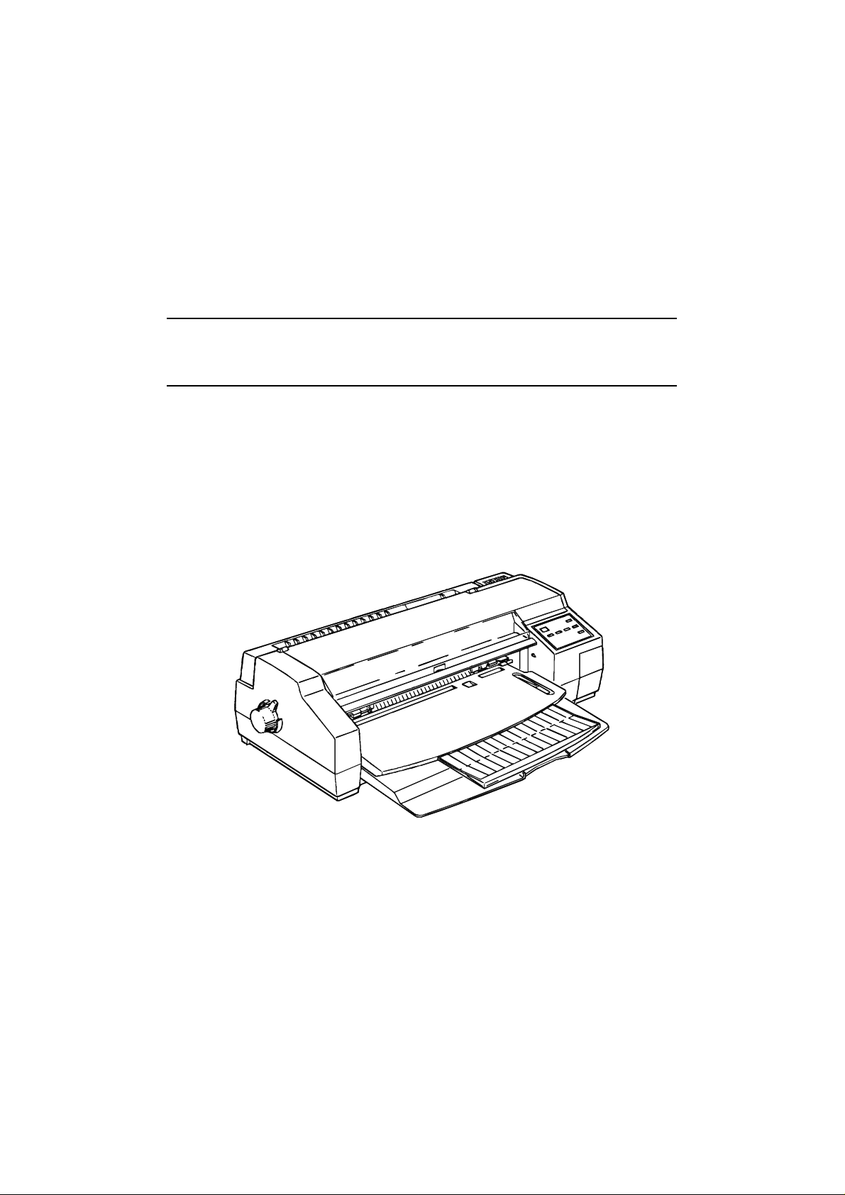
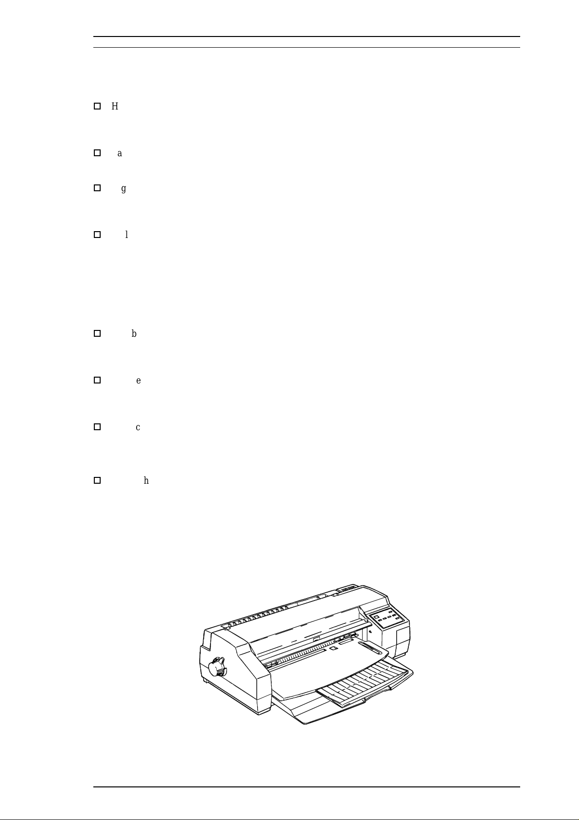
Figure 1-1. Stylus 1500 Exterior View. . . . . . . . . . . . . . . . . . . . . . . . . . . . . . . . . 1-1
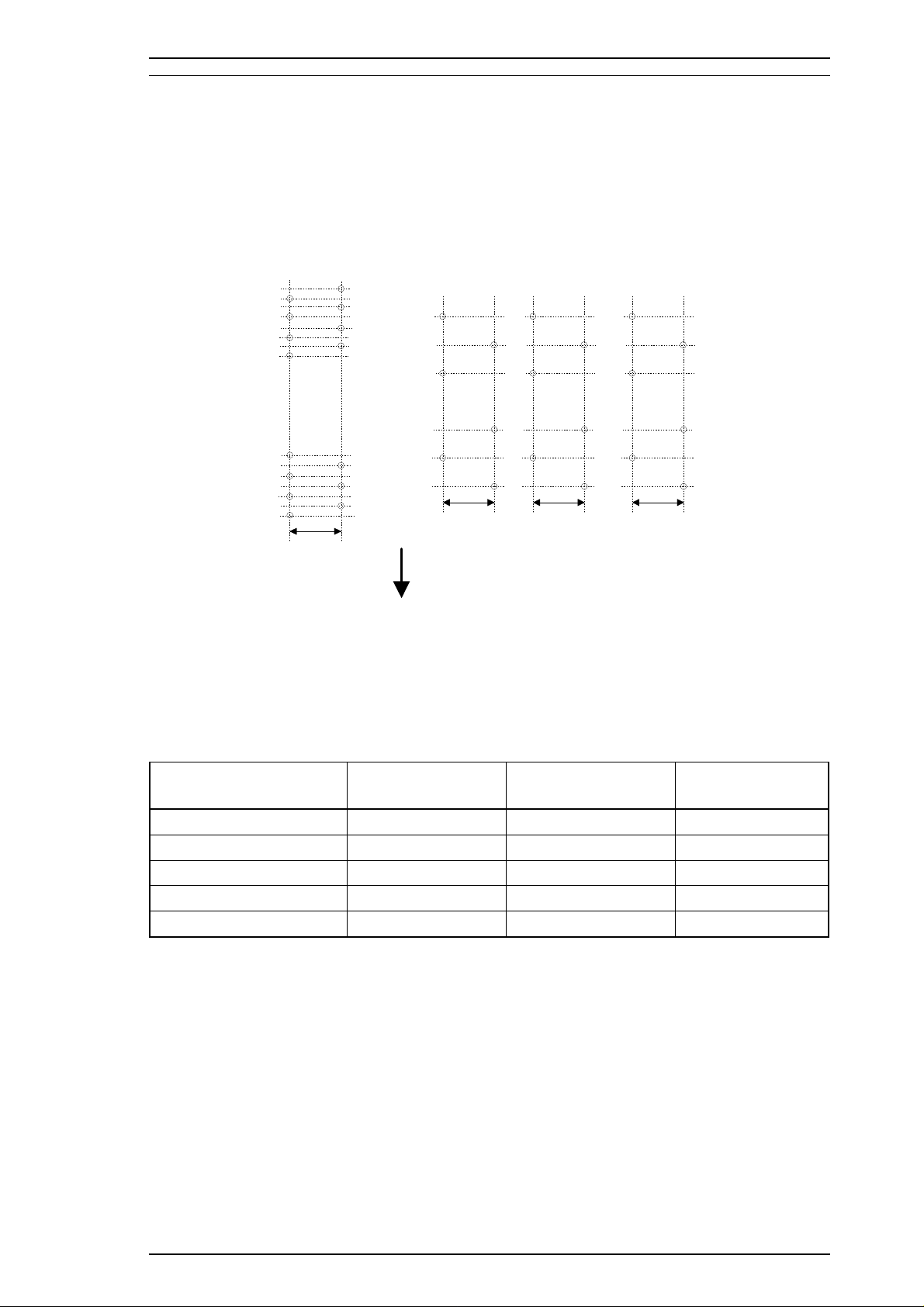
Figure 1-2. Nozzle Configuration . . . . . . . . . . . . . . . . . . . . . . . . . . . . . . . . . . . . 1-3
Figure 1-3. Environmental Conditions. . . . . . . . . . . . . . . . . . . . . . . . . . . . . . . . . 1-6
Figure 1-4. Data Transmission Timing . . . . . . . . . . . . . . . . . . . . . . . . . . . . . . . . 1-8
Figure 1-5. Control Panel Appearance . . . . . . . . . . . . . . . . . . . . . . . . . . . . . . . 1-13
Figure 1-6. Default Setting Flowchart . . . . . . . . . . . . . . . . . . . . . . . . . . . . . . . . 1-17
Figure 1-7. Sample Adjustment Pattern . . . . . . . . . . . . . . . . . . . . . . . . . . . . . . 1-20
Figure 1-8. Printable Area for Cut Sheets. . . . . . . . . . . . . . . . . . . . . . . . . . . . . 1-26
Figure 1-9. Printable Area for Envelopes . . . . . . . . . . . . . . . . . . . . . . . . . . . . . 1-27
Figure 1-10. Printable Area for Continuous Paper . . . . . . . . . . . . . . . . . . . . . . 1-28
Figure 1-11. Adjust Lever Settings . . . . . . . . . . . . . . . . . . . . . . . . . . . . . . . . . . 1-29
Figure 1-12. C172 MAIN Board Component Layout . . . . . . . . . . . . . . . . . . . . . 1-32
Figure 1-13. C172 PSB/PSE Board Component Layout. . . . . . . . . . . . . . . . . . 1-32
List of Tables
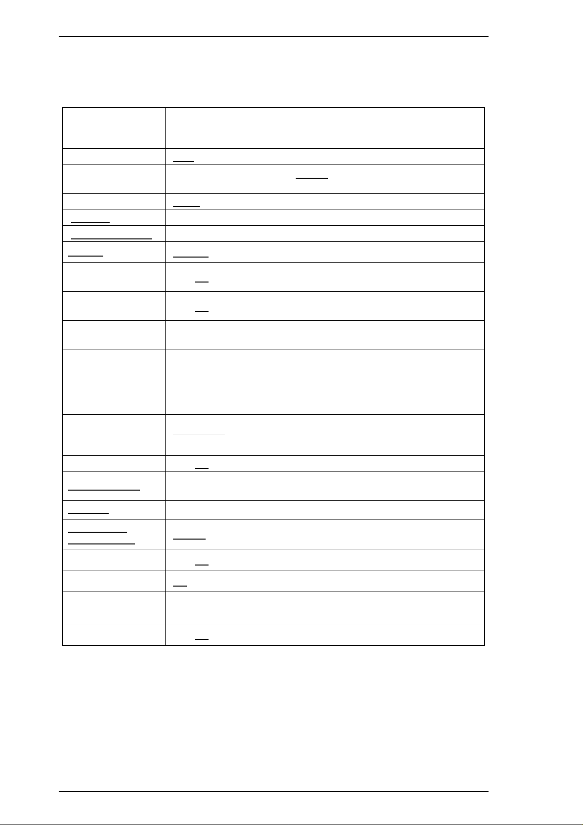
Table 1-1. Options and Consumables . . . . . . . . . . . . . . . . . . . . . . . . . . . . . . . . 1-2
Table 1-2. Print Speeds and Printable Columns. . . . . . . . . . . . . . . . . . . . . . . . . 1-3
Table 1-3. Character Tables and Fonts . . . . . . . . . . . . . . . . . . . . . . . . . . . . . . . 1-4
Table 1-4. Connector Pin Assignments and Signals (Forward Channel) . . . . . . 1-9
Table 1-5. Connector Pin Assignments and Signals (Reverse Channel) . . . . . 1-11
Table 1-6. Panel Functions at Power On . . . . . . . . . . . . . . . . . . . . . . . . . . . . . 1-15
Table 1-7. Indicator Status . . . . . . . . . . . . . . . . . . . . . . . . . . . . . . . . . . . . . . . . 1-16
Table 1-8. Default Settings. . . . . . . . . . . . . . . . . . . . . . . . . . . . . . . . . . . . . . . . 1-18
Table 1-9. Print Direction Mode Characteristics . . . . . . . . . . . . . . . . . . . . . . . . 1-19
Table 1-10. Printing Direction and ESC U Command. . . . . . . . . . . . . . . . . . . . 1-19
Table 1-11. Cut Sheet Specifications . . . . . . . . . . . . . . . . . . . . . . . . . . . . . . . . 1-23
Table 1-12. Transparency Specifications . . . . . . . . . . . . . . . . . . . . . . . . . . . . . 1-23
Table 1-13. Envelope Specifications. . . . . . . . . . . . . . . . . . . . . . . . . . . . . . . . . 1-23
Table 1-14. Index Card Specifications . . . . . . . . . . . . . . . . . . . . . . . . . . . . . . . 1-24
Table 1-15. Label (Cut Sheet) Specifications . . . . . . . . . . . . . . . . . . . . . . . . . . 1-24
Table 1-16. Continuous Paper Specifications. . . . . . . . . . . . . . . . . . . . . . . . . . 1-24
Table 1-17. Label (Continuous Paper) Specifications. . . . . . . . . . . . . . . . . . . . 1-24
Table 1-18. Banner Specifications . . . . . . . . . . . . . . . . . . . . . . . . . . . . . . . . . . 1-25
Table 1-19. Minimum Margins for Different Cut Sheet Sizes . . . . . . . . . . . . . . 1-26
Table 1-20. Minimum Margins for Envelopes . . . . . . . . . . . . . . . . . . . . . . . . . . 1-27
Table 1-21. Adjust Lever Position. . . . . . . . . . . . . . . . . . . . . . . . . . . . . . . . . . . 1-29
Page 7
Stylus 1500 Service Manual General Description
1.1 FEATURES
The Stylus 1500 is a business-use, high-speed, and high-quality color ink jet printer. The main features of this
printer are:
o
High print quality for color graphics
720 dpi printing
High Speed semi 720 dpi printing
o
Large capacity black ink cartridge
3 million characters (LQ mode)
o
High-speed printing
LQ printing at 200 cps
Draft printing at 400 cps
o
Built-in auto sheet feeder and push tractor
This holds:
Envelope to A2 size portrait
100 cut sheets, using 14 lb (55 g/m
10 envelopes
50 transparency sheets
70 sheets of special paper
o
Two built-in interfaces
Bidirectional parallel I/F (IEEE-P1284 compatible)
Type-B I/F
o
Easy setup
Multilingual messages (five languages), selected using the control panel
No DIP switches
o
Four scalable fonts, five LQ fonts, and one draft font installed
Scalable fonts: Roman T, Sans Serif H, Roman, Sans Serif
LQ bitmap fonts: Roman, Sans Serif, Courier, Prestige, Script
o
Useful character tables
Standard: Italic, PC437, PC850, PC860, PC861, PC863, PC865, BRASCII,
NLSP: Italic, PC437, PC437 Greek, PC850, PC852, PC853, PC855, PC857,
2
) paper
Abicomp, Roman 8, ISO Latin 1
PC866, PC869, MAZOWIA, Code MJK, ISO 8859-7, ISO Latin 1T,
Bulgaria, Roman 8, PC774, Estonia, ISO Latin 1, ISO Latin 2,
PC866 LAT
Figure 1-1. Stylus 1500 Exterior View
Rev. A 1-1
Page 8
General Description Stylus 1500 Service Manual
Table 1-1. Options and Consumables
Model Description
C83216* Color upgrade kit
C823071 / C823081 32 KB serial interface card
C82310* 32 KB parallel interface card
C82313* 32 KB IEEE-488 interface card
C82315* TWAIN interface card
C82312* Coax interface card
TM
C82312* LocalTalk
C82331* Ethernet interface card
C836021 / C836022
Parallel interface cable
(from D-SUB 25-pin to Amphenol 57)
interface card
C836031 / C836061
C836051 / C836061
S020062 Monochrome ink cartridge
S020049 Color ink cartridge
S041059 Exclusive paper (360 dpi) A4
S041060 Exclusive paper (360 dpi) Letter
S041065 Exclusive paper (360 dpi) A3
S041066 Exclusive paper (360 dpi) Super A3 / B
S041077 Exclusive paper (360 dpi) A2
S041066 Exclusive paper (720 dpi) A4
S041062 Exclusive paper (720 dpi) Letter
S041067 Exclusive paper (720 dpi) Legal
S041068 Exclusive paper (720 dpi) A3
S041069 Exclusive paper (720 dpi) Super A3 / B
S041070 Exclusive paper (720 dpi) B
S041076 Exclusive paper (720 dpi) A2
S041071 High quality glossy paper A4
S041072 High quality glossy paper Letter
S041073 High quality glossy paper A3
S041074 High quality glossy paper Super A3 / B
S041075 High quality glossy paper B
S041063 Transparency A4
S041064 Transparency Letter
S041054 Super coated index card for 720 dpi A6
Serial interface cable
(from D-SUB 25-pin to D-SUB 25-pin)
Serial interface cable
(from D-SUB 9-pin to D-SUB 25-pin)
* : The asterisk mean substitute for the last digit, which varies by each destinations.
1-2 Rev. A
Page 9
Stylus 1500 Service Manual General Description
1.2 SPECIFICATIONS
This section provides detailed information about the Stylus 1500.
1.2.1 Printing Specifications
Printing method: On-demand ink jet
Nozzle configuration: Monochrome: 64 nozzles (32 x 2 staggered)
Color: 60 nozzles (20 x 3, magenta, cyan, yellow)
#63
#61
#59
#57
#7
#5
#3
#1
0.847 mm
(12/360")
Monochrome
#64
#62
#60
#58
#6
#4
#2
Paper Feed Direction
#20
#2
1.129 mm
(16/360")
Magenta
#20
#19
#3
#2
#1
1.129 mm
(16/360")
#19
#3
#1
Cyan
Figure 1-2. Nozzle Configuration
Printing direction: Bidirectional with logic-seeking
#20
#2
1.129 mm
(16/360")
Yello w
#19
#3
#1
Table 1-2. Print Speeds and Printable Columns
Character Pitch Printable Columns LQ Speed Draft Speed
10 cpi (pica) 136 200 cps 400 cps
12 cpi (elite) 163 240 cps 480 cps
15 cpi 204 300 cps 600 cps
17 cpi (pica condensed) 233 343 cps 686 cps
20 cpi (elite condensed) 160 400 cps 800 cps
Control codes: ESC/P2 and extended raster graphics codes
EPSON remote commands
IBM XL24E emulation
Rev. A 1-3
Page 10
General Description Stylus 1500 Service Manual
Fonts:
Bitmap LQ fonts: EPSON Roman 10 cpi, 12 cpi, 15 cpi, Proportional
EPSON Sans Serif 10 cpi, 12 cpi, 15 cpi, Proportional
EPSON Courier 10 cpi, 12 cpi, 15 cpi
EPSON Prestige 10 cpi, 12 cpi, 15 cpi
EPSON Script 10 cpi, 12 cpi, 15 cpi
Scalable fonts: EPSON Roman 10.5 pt., 8 pt. - 32 pt. (in units of 2 pt.)
EPSON Sans Serif 10.5 pt., 8 pt. - 32 pt. (in units of 2 pt.)
EPSON Roman T 10.5 pt., 8 pt. - 32 pt. (in units of 2 pt.)
EPSON Sans Serif H 10.5 pt., 8 pt. - 32 pt. (in units of 2 pt.)
Note: Each typeface has four variations (normal, bold, italic, and bold italic).
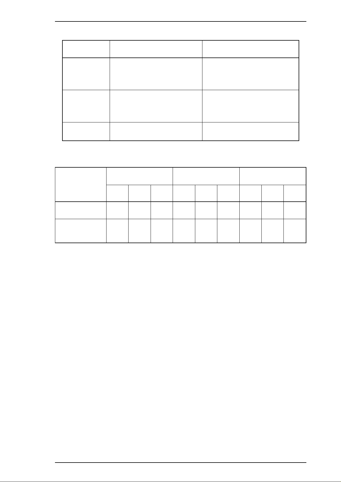
Table 1-3. Character Tables and Fonts
Standard
Version
NLSP
Version
Character Tables
Italic
PC437 (U.S., Standard Europe)
PC850 (Multilingual)
PC860 (Portuguese)
PC861 (Icelandic)
PC863 (Canadian-French)
PC865 (Nordic)
BRASCII
Abicomp
Roman 8
ISO Latin 1
Italic
PC437 (U.S., Standard Europe)
PC437 (Greek)
PC850 (Multilingual)
PC852 (East Europe)
PC853 (Turkish)
PC855 (Cyrillic)
PC857 (Turkish)
PC866 (Russian)
PC869 (Greek)
MAZOWIA (Poland)
Code MJK (CSFR)
ISO 8859-7 (Latin/Greek)
ISO Latin 1T (Turkish)
Bulgaria
Roman 8
PC774
Estonia
ISO Latin 1
ISO Latin 2
PC866 LAT
Bitmap
Fonts
EPSON
Roman
EPSON
Sans Serif
EPSON
Courier
EPSON
Prestige
EPSON
Script
Supported Supported Supported
Supported Supported
Scalable Fonts
EPSON
Roman
EPSON
Sans Serif
EPSON
Roman T
EPSON
Sans Serif H
None
supported
1-4 Rev. A
Page 11

Stylus 1500 Service Manual General Description
1.2.2 Paper Feeding
Feeding method: Friction feed with built-in auto sheet feeder (ASF)
and push tractor feed
Note : Reverse feeding beyond 9.5 mm (0.38") is not allowed.
Line spacing: 1/6 inch, 1/8 inch, or programmable in units of 1/360 inch
Paper path: Cut sheet front entry / front exit by ASF
Single sheet rear entry / front exit and continuous paper rear
entry / front exit
Feeding speed: 71 ms (1/6 inch)
3 inches/second (continuous feeding)
1.2.3 Input Data Buffer
Capacity: 256 KB
1.2.4 Electrical Specifications
120 V Version
Rated voltage: 120 VAC
Input voltage range: 103.5 - 132 VAC
Rated frequency range: 50 - 60 Hz
Input frequency range: 49.5 - 60.5 Hz
Rated current: 0.7 A
Power consumption: Approximately 23 W (self-test with 10-cpi LQ characters)
Insulation resistance:
Dielectric strength: 1000 VAC RMS - 1 minute or 1200 VAC RMS - 1 second
10 MΩ minimum (500 VDC between AC line and chassis)
(between AC line and chassis)
220 V Version
Rated voltage: 220 - 240 VAC
Input voltage range: 198 - 264 VAC
Rated frequency range: 50 - 60 Hz
Input frequency range: 49.5 - 60.5 Hz
Rated current: 0.4 A
Power consumption: Approximately 20 W (self-test with 10-cpi LQ characters)
Insulation resistance:
Dielectric strength: 1000 VAC RMS - 1 minute or 1200 VAC RMS - 1 second
10 MΩ minimum (500 VDC between AC line and chassis)
(between AC line and chassis)
Rev. A 1-5
Page 12

Humidity
(% RH)
˚C
(˚F)
80%
55%
20%
10˚C
(50˚F)
27˚C
(80˚F)
35˚C
(95˚F)
Guaranteed Range
General Description Stylus 1500 Service Manual
1.2.5 Environmental Conditions
Temperature:
Operating: 10 to 35° C
Non-operating: –20 to 40° C
*1
Non-operating:
–20 to 60° C
1 month at 40° C
120 hours at 60° C
Humidity: Operating:
Non-operating:
*2
*1, *2
20 to 80% RH
5 to 80% RH
Resistance to shock: Operating: 1G, within 1 ms
Non-operating:
*1
2 G, within 2 ms
Resistance to vibration: Operating: 0.15 G
Non-operating:
*1
0.50 G
Notes: *1 In shipment container. *2 Without condensation.
Figure 1-3. Environmental Conditions
1.2.6 Reliability
Total print volume: 75,000 pages (letter or A4)
Printhead life: 1,000 million dots/nozzle
1.2.7 Safety Approvals
120 V Version
Safety standards: UL 1950 with D3
CSA 22.2 950 with D3
EMC: FCC part 15 subpart B class B
220 - 240 V Version
Safety standards: EN 60950 (TÜV, SEMKO, DEMKO, NEMKO, FIMKO)
EMC: EN 55022 (CISPR Pub. 22) class B
EN 50082-1
1-6 Rev. A
Page 13

Stylus 1500 Service Manual General Description
1.2.8 CE Marking
220 - 240 V Version
Lower Voltage Directive 73/23/EEC: EN60950
EMC Directive 89/336/EEC: EN55022 Class B
EN50082-1
IEC801-2
IEC801-3
IEC801-4
1.2.9 Acoustic Noise
Noise level: Approximately 45 dB(A) (according to ISO 7779)
Rev. A 1-7
Page 14
General Description Stylus 1500 Service Manual
1.3 INTERFACES
1.3.1 Hardware Interfaces
This section describes the Stylus 1500 interfaces. The printer is standard-equipped with a parallel interface.
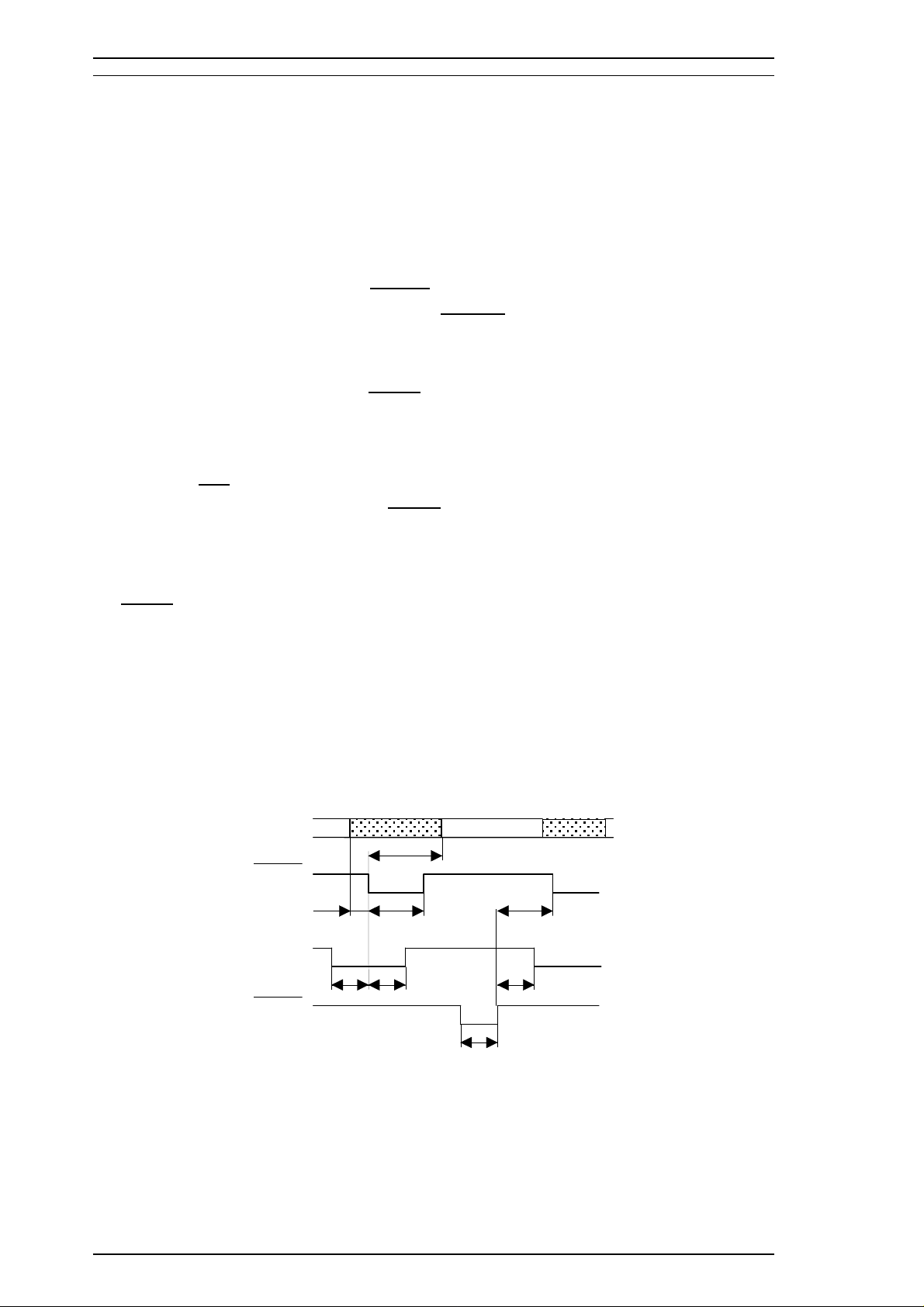
1.3.1.1 Parallel Interface
Forward Channel
Transmission mode: 8 bit parallel, IEEE-P1284 compatibility mode
Synchronization:
Handshaking: BUSY and
Signal level: TTL-compatible level (IEEE-P1284 Level 1 device)
Adaptable connector: 57-30360 (Amphenol or equivalent)
STROBE pulse
ACKNLG signal
The BUSY signal is set HIGH before either
ERROR is set LOW or PE is set HIGH, and BUSY is held HIGH
until all these signals return to the inactive state. The BUSY signal goes HIGH in the following cases:
o During data entry (See Figure 1-4 below.)
o When the input data buffer is full.
o When the
o During a printer error condition (See the
INIT signal is LOW or during hardware initialization.
ERROR signal description below.)
o During self-test printing.
o In default setting mode.
o When the parallel interface is not selected.
ERROR signal is LOW when the printer is in one of the following conditions:
The
o Printer hardware error (fatal error).
o Paper-out error.
o Release lever operation error.
The PE signal is HIGH during a paper-out error.
DATA
DATA (n)
DATA (n+1)
STROBE
500 ns (min.) 500 ns (min.)
BUSY
ACKNLG
* : The rise and fall time of every output signal must be less than 120 ns.
The rise and fall time of every input signal must be less than 200 ns.
500 ns (min.)
0 (min.) 500 ns (max.)
0 (min.)
0 (min.)
500 ns ~10 µs
Figure 1-4. Data Transmission Timing
1-8 Rev. A
Page 15
Stylus 1500 Service Manual General Description
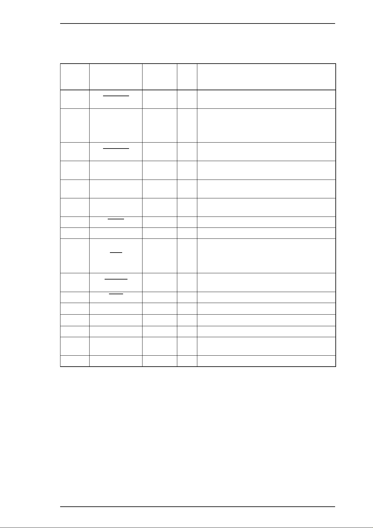
Table 1-4 shows the connector pin assignments and signals for the forward channel of the parallel interface.
Table 1-5 shows this information for the reverse channel.
Table 1-4. Connector Pin Assignments and Signals (Forward Channel)
Pin No. Signal Name
1
2 - 9 DATA 0 - 7 20 - 27
10
11 BUSY 29
12 PE 28 O
13 SLCT 28 O
14
15 NC — — Not connected.
31
STROBE 19 I
ACKNLG 28
AFXT 30 I
INIT 30 I
Return
GND Pin
I/O Description
Reading of data is performed at the falling
edge of this pulse.
Signals DATA0 - DATA7 represent data bits 0
to 7, respectively. Each signal is HIGH when
I
the data is logical 1 and LOW when the data is
logical 0.
This signal is a negative pulse indicating that
O
the printer can accept more data.
When this signal is HIGH, the printer cannot
O
receive data.
When this signal is HIGH, the printer detects a
paper-out error.
This signal is always HIGH when the printer is
powered on.
The falling edge of a negative pulse or a LOW
signal on this line causes the printer to
initialize. A 50 µs (minimum) pulse is
necessary.
When this signal is LOW, the printer detects an
32
36
18 Logic H — O
35 +5 V —
17 Chassis GND —
16, 33
19 - 30
15, 34 NC —
ERROR 29
SLIN 30 I Not used.
GND —
O
error.
Pulled up to +5 V via a 3.9 KΩ resistor.
O
Pulled up to +5 V via a 3.3 KΩ resistor.
—
Chassis ground.
—
Signal ground.
—
Not used.
Note: The I/O column indicates the direction of the signal as viewed from the printer.
Rev. A 1-9
Page 16

General Description Stylus 1500 Service Manual
Reverse Channel
Transmission mode: IEEE-P1284 nibble mode
Adaptable connector: See the Forward Channel section earlier in this manual.
Synchronization: Refer to the IEEE-P1284 specification.
Handshaking: Refer to the IEEE-P1284 specification.
Data transmission timing: Refer to the IEEE-P1284 specification.
Signal level: Refer to the IEEE-P1284 specification.
Extensibility request: The printer responds affirmatively when the extensibility request
values are 00H or 04H, as follows:
00H: Request nibble mode reverse channel transfer
04H: Request device ID
Return data using nibble mode channel transfer
Device ID: The printer sends following device ID string when requested:
ESC/P2
00H 36H
MFG: EPSON;
CMD: ESCPL2-00;
MDL: Stylus 1500;
CLS: PRINTER;
XL24E
00H 37H
MFG: EPSON;
CMD: PRPXL24-00;
MDL: Stylus 1500;
CLS: PRINTER;
Note: 00H denotes a hexadecimal value of zero.
1-10 Rev. A
Page 17
Stylus 1500 Service Manual General Description
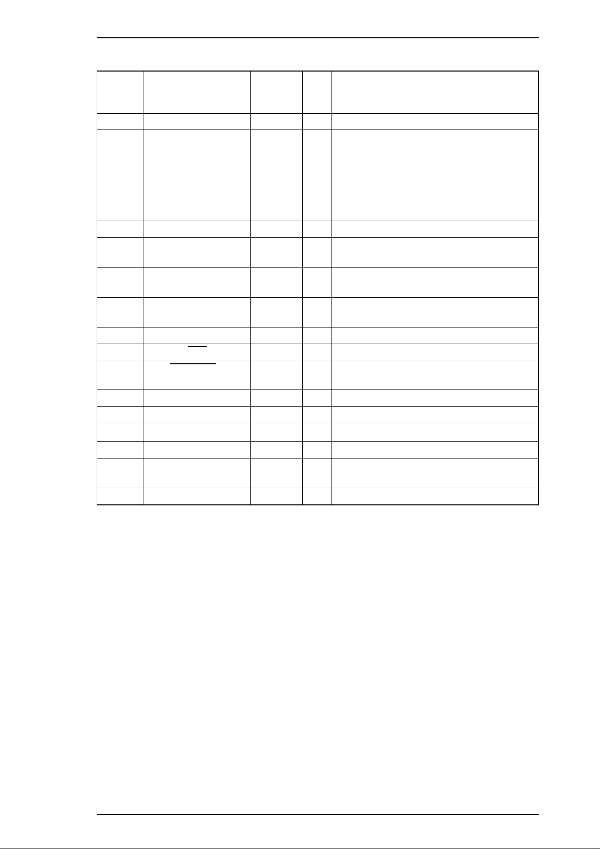
Table 1-5. Connector Pin Assignments and Signals (Reverse Channel)
Pin No. Signal Name
1 Host Clk 19 I Host clock signal.
2 - 9 DATA 0 - 7 20 - 27 I
10 PtrClk 28 O Printer clock signal.
11
12
13 Xflag / Data Bits 1, 5 28 O
14 Host Busy 30 I Host busy signal.
31
32
36 1284-Active 30 I Active signal for IEEE-P1284 mode.
18 Logic-H — O
35 +5 V — O
17 Chassis GND — — Chassis ground.
16, 33
19 - 30
15, 34 NC — — Not connected.
Ptr Busy /
Data Bits 3, 7
Ack Data Req /
Data Bits 2, 6
INIT 30 I Not used.
Data Avail /
Data Bits 0, 4
GND — — Signal ground.
Return
GND Pin
29 O
28 O
29 O
I/O Description
Signals DATA0 - DATA7 represent data
bits 0 to 7, respectively. Each signal is
HIGH when the data is logical 1 and LOW
when the data is logical 0. These signals
are used to transfer the extensibility request
values (described in IEEE-P1284) to the
printer.
Printer busy signal and reverse channel
transfer data bit 3 or 7.
Acknowledge data request signal and
reverse channel transfer data bit 2 or 6.
X-flag signal and reverse channel transfer
data bit 1 or 5.
Data available and reverse channel transfer
data bit 0 or 4.
Pulled up to +5 V via a 3.9 KΩ resistor.
Pulled up to +5 V via a 3.3 KΩ resistor.
Note: The I / O column indicates the direction of the signal as viewed from the printer.
1.3.1.2 Optional Interface
The Stylus 1500 supports an optional Type-B interface with the following characteristics:
Reply Message: ESC/P2 is selected:
Main type: MTP48p, PW136cl10cpi, PRG(L0xxxx)rev,AP800ma
Product name: Stylus 1500
Emulation type: ESCPL2-00
Entity type: EPSON LQ2
XL24E is selected:
Main type: MTP48p, PW136cl10cpi, PRG(L0xxxx)rev,AP800ma
Product name: Stylus 1500
Emulation type: PRPXL24-00
Entity type: EPSONPRPXL24
Rev. A 1-11
Page 18

General Description Stylus 1500 Service Manual
1.3.2 Printer Languages and Control Codes
Printer languages and control codes: ESC/P2
IBM 24XL
EPSON Remote
1-12 Rev. A
Page 19
Stylus 1500 Service Manual General Description
1.4 OPERATIONS
This section describes the controls, settings, and adjustments used to operate the Stylus 1500.
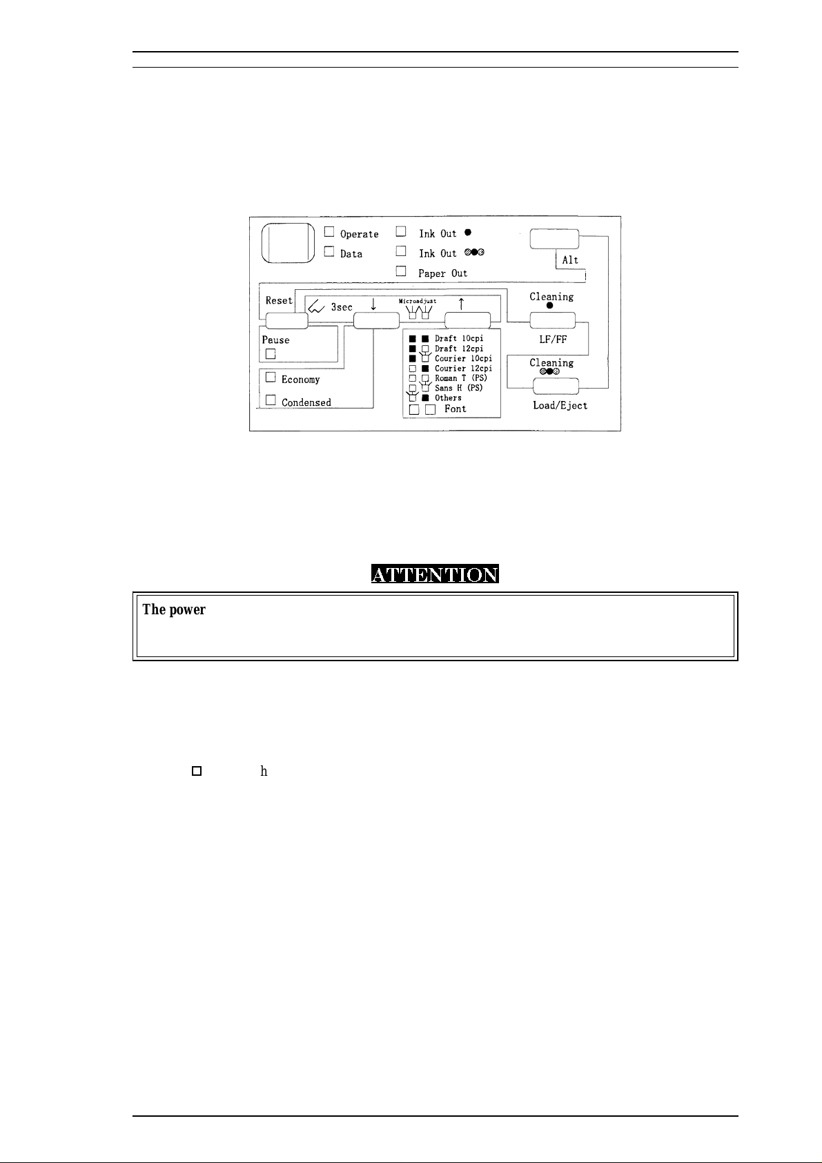
1.4.1 Control Panel
The control panel for this printer is in the center of the upper case. The panel has 1 lock-type and 6
non-lock-type pushbuttons, and 10 LED indicators for easy operation of the various print functions.
Figure 1-5. Control Panel Appearance
1.4.1.1 Buttons
Power
This button turns the printer on or off.
ATTENTION
The power button controls the secondary power supply circuit. Therefore, the primary circuit is
hot after power off. Do not connect the interface cable even if the printer power is off while the
AC inlet is connected. Otherwise, the circuit board or interface may be damaged.
Pause
This button alternates between printing and non-printing states when there is data in the print buffer. In the
pause state, printing stops but communication with the I/F does not stop. Therefore, even in the pause state,
the printer receives data from the host until the input data buffer is full.
o
Pressing the Pause button while holding down the Alt button resets the printer.
Alt
This button is usually used with another button.
o Holding down Alt for 3 seconds moves the printer carriage to the ink cartridge
installation position. Pressing Alt again returns the carriage to the home position.
LF/FF
This button feeds one line or a page.
o Pressing LF/FF while holding down Alt starts the black printhead cleaning cycle.
Economy/Condensed
This button selects economy or condensed printing mode.
Rev. A 1-13
Page 20

General Description Stylus 1500 Service Manual
Font
This button selects the desired font.
o
Pressing Font while holding down Alt starts the color printhead cleaning
cycle.
Load/Eject
This button loads and ejects the paper.
1.4.1.2 Indicators
Operate (green)
Lights when the printer power is on.
Data (orange)
o
Lights when there is data in the print buffer.
o
Blinks with the Pause LED when an error occurs.
Black Ink Out (red)
Lights when there is no ink in the black ink cartridge, and blinks when the cartridge is low.
Color Ink Out (red)
Lights when there is no ink in the color ink cartridge, and blinks when the cartridge is low.
Paper Out (red)
Lights when the printer is out of paper, and blinks when a paper jam occurs.
Pause (orange)
Lights when printing is paused.
Economy (green)
Lights when economy printing mode is selected.
Condensed (green)
Lights when condensed printing mode is selected.
Font (green)
Shows the selected font.
1-14 Rev. A
Page 21
Stylus 1500 Service Manual General Description
1.4.2 Panel Functions at Power On
The table below describes the functions performed when the indicated buttons are held down while turning on
the printer.
Table 1-6. Panel Functions at Power On
Button Function at Printer Power On
Alt Starts demonstration printing.
Economy/Condensed Enters default setting mode.
Pause Enters print adjustment mode.
Load/Eject Starts LQ mode self-test printing.
LF/FF Starts Draft mode self-test printing.
Alt + Pause Enters ink smudge prevention mode.
LF/FF + Load/Eject Enters hex dump mode.
Alt + Economy/Condensed + LF/FF +
Pause
Notes: 1. “+” means to press one button while holding down the other button(s).
2. The EEPROM and Timer IC must be reset only by qualified service personnel.
Enters reset mode for the EEPROM and Timer IC
(for factory and service use only).
Rev. A 1-15
Page 22
General Description Stylus 1500 Service Manual
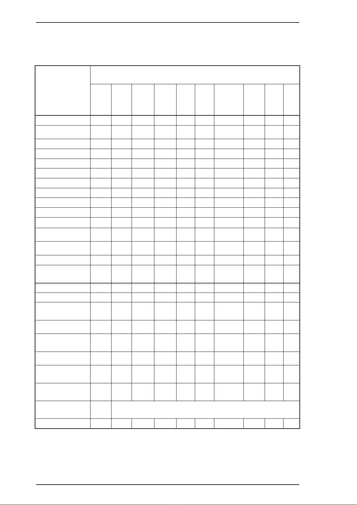
1.4.3 Printer Conditions and Status
The table below shows how the printer LEDs indicate status and operating conditions.
Table 1-7. Indicator Status
LEDs
Printer Status
Power Data
Power on On — — — — — — — — —
Capping after
power off
Data present — On — — — — — — — —
Economy mode — — — — — On — — — —
Condensed mode — — — — — — On — — —
Pause — — — — — — — On — —
Micro adjust mode — — — — — — — — Blink Blink
Draft 10 cpi — — — — — — — — Off Off
Draft 12 cpi — — — — — — — — Off On
Courier 10 cpi — — — — — — — — Off Blink
Courier 12 cpi — — — — — — — — On Off
Roman T
Proportional
Sans Serif H
Proportional
Ink sequence — — — — — — — Blink — —
Ink cartridge
change mode
Paper out — — — — On — — — — —
Paper jam — — — — Blink — — — — —
No ink cartridge
or ink end (black)
Ink level low
(black)
No ink cartridge
or ink end (color)
Ink level low
(color)
Release lever
error
Blink — — — — — — — — —
——— ——— — —OnOn
— — — — — — — — On Blink
— — — — — — — Blink — —
— — On — — — — — — —
— — Blink — — — — — — —
———On—— — ———
— — — Blink — — — — — —
— Blink — — Blink — — — — —
Ink
Out
(Black)
Ink
Out
(Color)
Paper
Out
Econ-
omy
Con-
densed
Pause
FontLFont
R
Maintenance
request
EEPROM and
timer reset
Fatal error — Blink — — — — — Blink — —
Blink Blink Blink Blink Blink Blink Blink Blink Blink Blink
— On (for 1 second only)
Note: “—” means that the indicated printer status does not affect the LED.
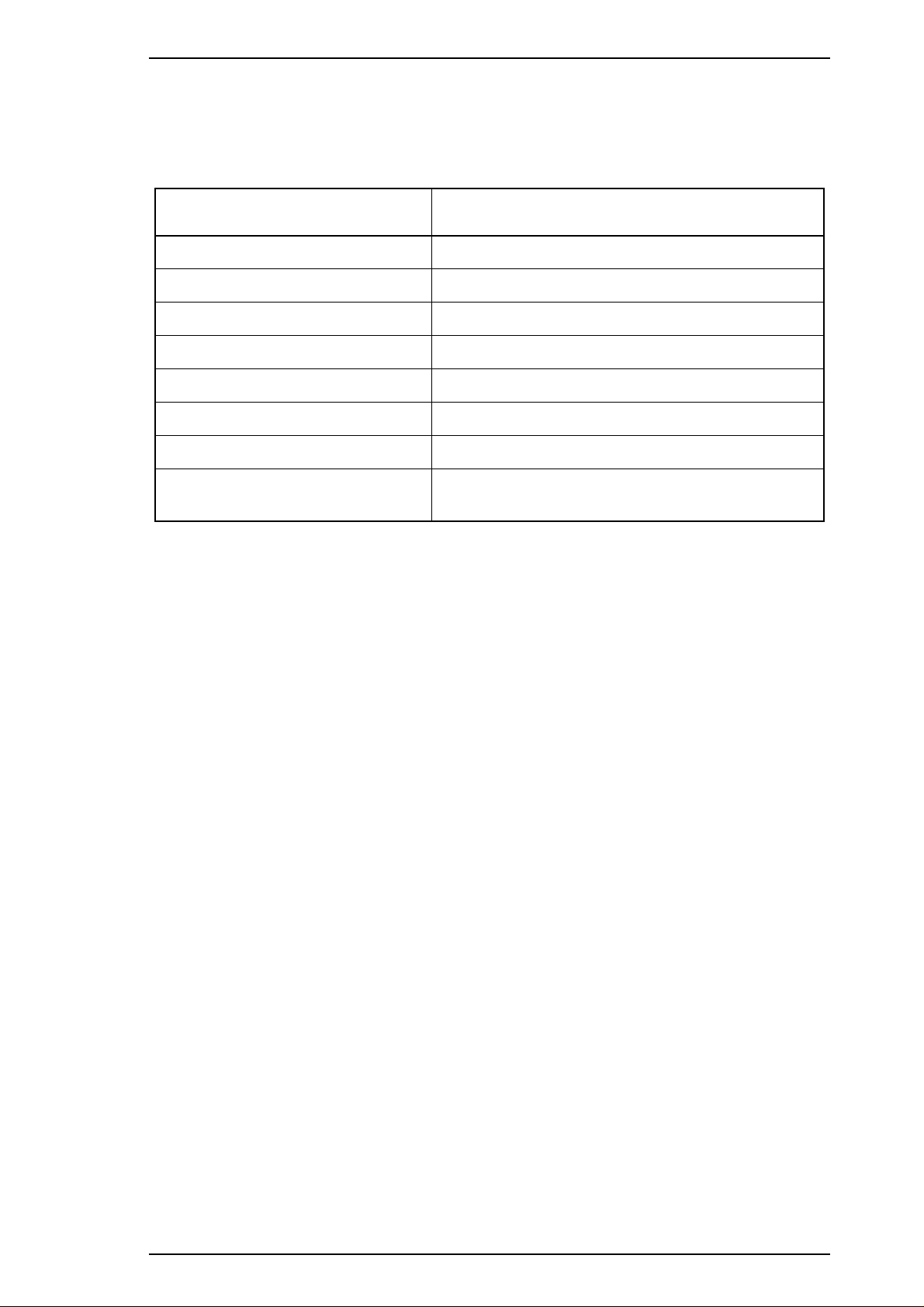
1.4.4 Default Settings
This printer has user-selectable default settings to which it refers at initialization. The default settings (and
factory settings ) are listed in Table 1-8.
1-16 Rev. A
Page 23
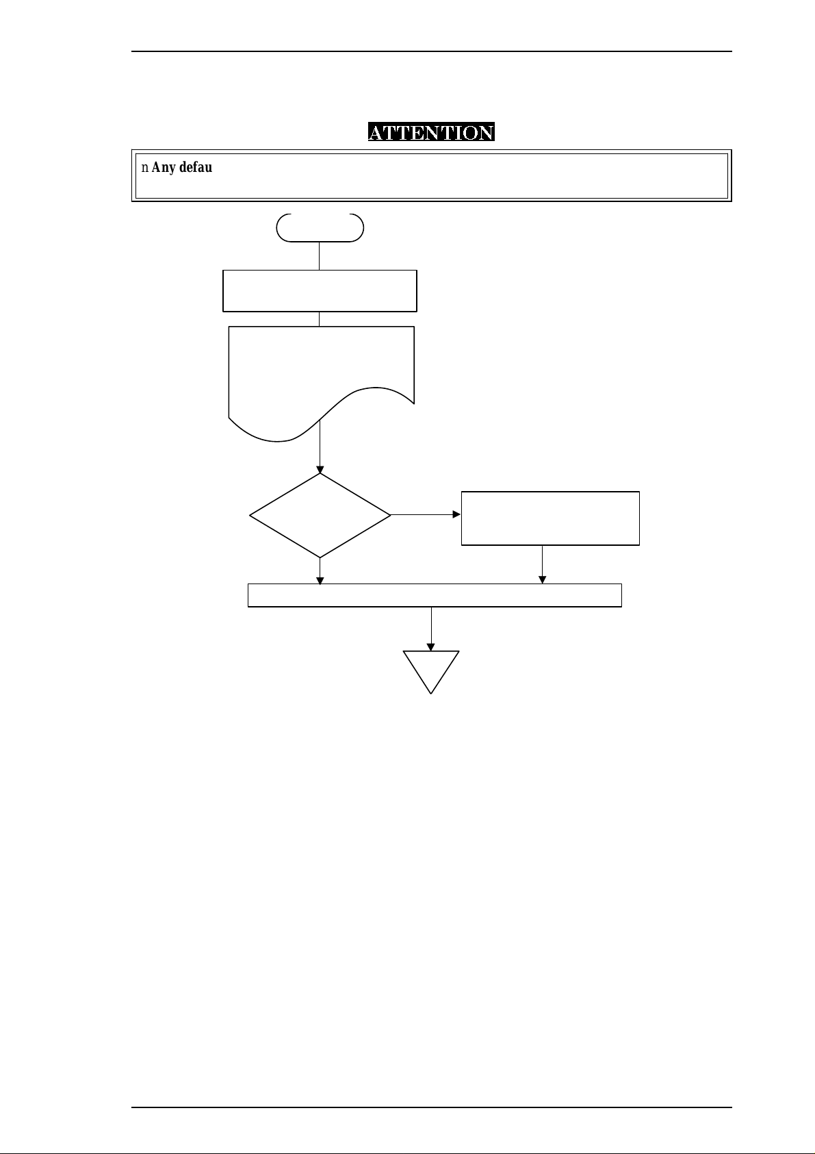
END
Change the settings?
YES
NO
Change setting menu:
Alt
button
Change setting value:
Pause
button
Turn printer power off to save settings to the EEPROM.on the main board
START
Hold down the Economy /Condensed
button, a nd tu rn on the print er.
The printer prints:
1. Firmware version,
Protec t co unte r va lue A/C.
2. How to set defaults.
3. Current settings.
Stylus 1500 Service Manual General Description
1.4.4.1 Setting Method
The method of setting defaults is shown in the flowchart below.
ATTENTION
n Any default value specified is not stored in the EEPROM until the printer is turned off.
n The last default value specified before power-off is stored in the EEPROM.
Figure 1-6. Default Setting Flowchart
Rev. A 1-17
Page 24
General Description Stylus 1500 Service Manual
1.4.4.2 Setting Menus
The default setting menus are described in the table below.
Table 1-8. Default Settings
Menus
Print direction
Font
Pitch
*1
Auto / Bi-D / Uni-D
Draft / Roman / Sans Serif /
Sans Serif H
10 cpi / 12 cpi / 15 cpi / 17.1 cpi / 20 cpi / Proportional
(underlines indicate factory default settings)
I/F mode Auto / Parallel / Serial
Auto I/F wait mode 10 seconds / 30 seconds
Software
Auto CR
(IBM mode only)
AGM
(IBM mode only)
Character tables
(standard version)
ESC/P2 / IBM X24E
Off
On /
Off
On /
Italic PC 437 PC 850 PC 860 PC 863 PC 865
PC 861 BRASCII Abicomp Roman 8 ISO Latin 1
Italic PC 437 PC 437 Greek PC 850 PC 853
Character tables
(NLSP version)
PC 855 PC 852 PC 857 PC 866 PC 869
MAZOWIA Code MJK ISO 8859-7 ISO Latin 1T Bulgaria
Roman 8 PC774 Estonia ISO Latin 1 ISO Latin 2
PC866 LAT
Settings
Courier / Prestige / Script / Roman T /
International
character set for
italic table
Auto line feed On /
Network I/F mode
Zero slash
Page length for
continuous paper
Skip over perforation
Auto tear off
Print mode
*3
Paper roll
Italic U.S.A. Italic France Italic Germany Italic U.K.
Italic Denmark Italic Sweden Italic Italy Italic Spain 1
Off
Off: Used in standalone environment
On: Used in network environment
0 / 0 with slash
11 inch 12 inch 8.5 inch 70/6 inch Other
Off
On /
On / Off
Plain paper (pure black) / Plain paper (composite black) /
Exclusive paper / Transparency
On /
Off
Notes: *1. Refer to Tables 1-9 and 1-10.
*2. This is selected when a value other than 11, 12, 8.5, or 70/6 inches has been placed
in EEPROM by the ESC | command.
*3. This mode is provided only for DOS users and is selected according to paper type.
Pure black and composite black are selected according to the printed result.
*2
1-18 Rev. A
Page 25
Stylus 1500 Service Manual General Description
Table 1-9. Print Direction Mode Characteristics
Item Monochrome Printing Color Printing
• Throughput is better.
Auto Throughput and quality is better.
Bi-D
• Throughput is best.
• Print quality may be down.
• Color quality with special paper is
worse. (Color correction depends
on the printing direction.)
• Throughput is better.
• Color quality with special paper is
worse. (Color correction depends
on the printing direction.)
Uni-D
• Throughput is worse.
• Print quality is better.
• Throughput is worse.
• Color quality is best.
Table 1-10. Printing Direction and ESC U Command
Default Setting
Mode
Character mode
(for DOS)
Raster graphics
mode
(for Windows)
ESC U0ESC U
Auto
Bi-D Uni-D Auto Bi-D Uni-D Bi-D Bi-D Uni-D Uni-D
Note: Printing direction is controlled by a driver in the Windows environment.
Auto Bi-D Uni-D
None
1
Auto Auto Bi-D Uni-D Bi-D Uni-D Uni-D Uni-D
ESC U0ESC U
1
None
ESC U0ESC U
None
1
Rev. A 1-19
Page 26
General Description Stylus 1500 Service Manual
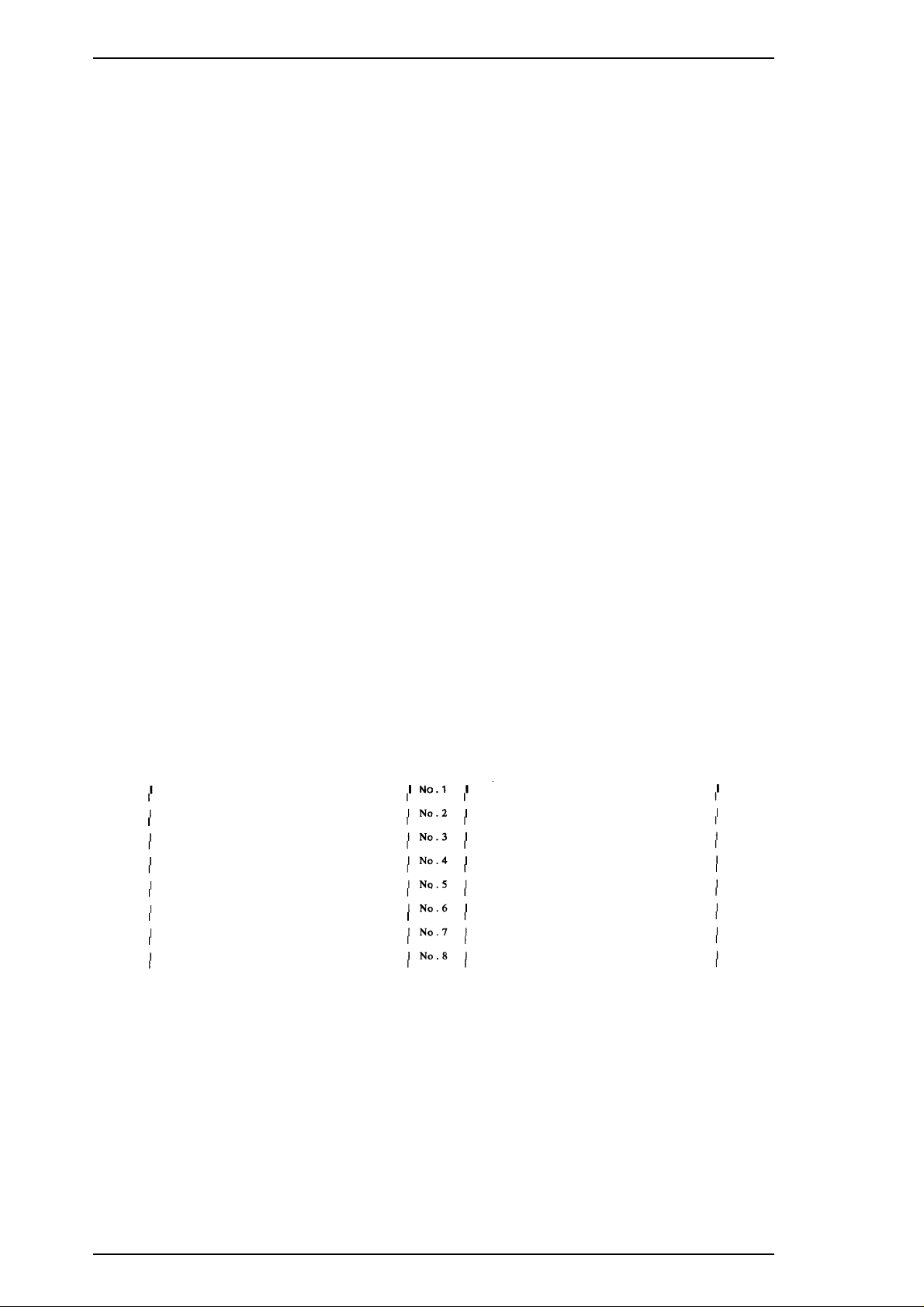
1.4.5 Printer Adjustment Mode
The Stylus 1500 allows the user to adjust the printing direction and head gap without a special program. The
following list shows the adjustments for this printer in order:
Pattern 1 Uni-D adjustment at 400 cps
Pattern 2 Bi-D adjustment at 100 cps
Pattern 3 Bi-D adjustment at 200 cps
Pattern 4 Bi-D adjustment at 400 cps
Pattern 5 Head gap adjustment (for the black and color printheads in the carriage movement direction
at 100 cps)
Pattern 6 Head gap adjustment (for the black and color printheads in the carriage movement direction
at 200 cps)
Pattern 7 Headgap adjustment (for the black and color printheads in the paper feed direction)*
* These adjustments are performed only when the color upgrade kit is installed in the printer.
Adjustment Method
Use the following steps to perform the adjustments:
1. Hold down the Pause button while turning on the power. The printer enters adjustment mode.
“Using this mode” and the pattern 1 are printed.
*
*
2. Select the number of the most closely aligned columns by pressing the Alt button.
The black Ink Out, color Ink Out, and Paper Out LEDs show the line number currently selected. This
selection advances once each time the Alt button is pressed, and the three LEDs change their
combination of On /Off / Blinking to indicate the selection.
3. Specify the selected number by pressing the Pause button.
The selected number is set, and the next pattern is printed.
Patterns 1
Figure 1-7. Sample Adjustment Pattern
1-20 Rev. A
Page 27
Stylus 1500 Service Manual General Description
4. Repeat steps 2 and 3 until the pattern No.4 or 7 is printed.
The adjustments are executed in the following order:
Pattern 1. Uni-D adjustment at 400 cps
Pattern 2. Bi-D adjustment at 100 cps
Pattern 3. Bi-D adjustment at 200 cps
Pattern 4. Bi-D adjustment at 400 cps
Pattern 5.
at 100 cps)
Pattern 6.
200 cps)
Pattern 7.
*
*
*
Head gap adjustment (for the black and color printheads in the carriage movement direction
Head gap adjustment (for the black and color printheads in the carriage movement direction at
Head gap adjustment (for the black and color printheads in the paper feed
direction at 360 dpi.)
* : When the optional color kit is not installed, the pattern 4 is the final pattern and the rest adjustments (pattern 5, 6 and 7)
are not executed.
ATTENTION
n Any adjustment value specified is not stored in the EEPROM untilthe printeris turned off.
n The last adjustment value specified before power-off is stored in the EEPROM..
n Before the whole adjustmentsare executed, the setting value is not stored in the printer.
5. Turn off the power to exit adjustment mode.
Rev. A 1-21
Page 28

General Description Stylus 1500 Service Manual
1.4.6 Printer Initialization
This printer has three initialization types: hardware, software, and panel.
1. Hardware Initialization
Hardware initialization is performed by turning on the printer or sending the INIT signal to the parallel interface. The following functions
are executed:
o The printer mechanism is initialized.
o The input data buffer is cleared.
o Downloaded character definitions are cleared.
o The print buffer is cleared.
o Default values are set.
2. Software Initialization
Software initialization is performed when the printer receives the ESC @ command. The following functions are executed:
o The print buffer is cleared.
o Default values are set.
Note: Thelast panel settings are kept after software initialization.
3. Panel Initialization
Panel initialization is performed by pressing the Load/Eject button while holding down the Alt button. The following functions are
executed:
o The input data buffer is cleared.
o The print buffer is cleared.
o Default values are set.
Note:
The last panel settings are kept after panel initialization.
1.4.7 Monochrome Printing Mode
This printer has a monochrome printing function that allows printing to continue with black ink when the color ink cartridge is out or the
color upgrade kit is not installed. This function is selected by the printer driver setting. To enter monochrome printing mode, turn the
Power button off and back on again.
Notes: 1. Once the printer has entered this function, print data must be resent.
2. The color select command (
ESC r
)isignored.
1-22 Rev. A
Page 29
Stylus 1500 Service Manual General Description
1.5 PAPER SPECIFICATIONS
1.5.1 Paper Type Specifications
1. Cut Sheets
Table 1-11. Cut Sheet Specifications
× 297 mm (11.7")
2
(14 lb) - 90 g/m2(24 lb)
Size
Thickness
Weight
Quality
A4: 210 mm (8.3")
Letter: 215.9 mm (8.5") × 279.4 mm (11.0" )
B5: 182 mm (7.2") × 257 mm (10.1")
Legal: 215.4 mm (8.5") × 355.6 mm (14.0")
B4: 257 mm (10.1") × 364 mm (14.3")
A3: 297 mm (11.7") × 420 mm (16.5")
Ledger: 279.4 mm (13.0") × 431.8 mm (17.0")
A3 wide: 329 mm (13.0") × 483 mm (19.0")
B3: 364 mm (14.3") × 514 mm (20.2")
A2: 420 mm (16.5") × 594 mm (23.4")
US C: 431.8 mm (17.0") × 558.8 mm (22")
B5 (ISO) 176 mm (6.9") × 250 mm (9.8")
B4 (ISO) 250 mm (9.8") × 353 mm (92.6")
0.065 mm (0.0025") - 0.11 mm (0.004")
ASF: 64 g/m2(17 lb) - 90 g/m2(24 lb)
Manual Insertion: 52g/m
Exclusive paper, bond paper, PPC, glossy paper
Note : The designated face must be used when printing on exclusive paper.
: A2 portrait, US-C portrait are used by manual insertion only.
2. Transparencies
Table 1-12. Transparency Specifications
Size
Thickness 0.075 mm (0.003") - 0.085 mm (0.0033")
Notes: 1. Printing on transparencies is supported only at normal temperatures.
2. The designated face must be used when printing on exclusive paper.
3. Envelopes
A4: 210 mm (8.3") × 297 mm (11.7")
Letter: 215.9 mm (8.5") × 279.4 mm (11.0")
Table 1-13. Envelope Specifications
No. 10: 241.3 mm (9.5") × 104.8 mm (4.125")
Size
Thickness 0.16 mm (0.006") - 0.52 mm (0.02")
Weight 45 g/m
Quality Exclusivepaper, bond paper, PPC, glossy paper
Notes: 1. Printing on envelopes is supported only at normal temperatures.
2. When inserting envelopes, keep the longer side horizontal.
3. When printing on envelopes, set the adjust lever to the proper position. (Refer to
Section 1.5.3, Adjust Lever Position.)
DL: 220 mm (8.7) × 110 mm (4.3")
C5: 229 mm (9") × 162 mm (6.4")
2
(12 lb) - 90 g/m2(24 lb)
Rev. A 1-23
Page 30
General Description Stylus 1500 Service Manual
4. Index Cards
Table 1-14. Index Card Specifications
Size
Thickness 0.23 mm (0.0091") and less
Note: When printing on index cards, set the adjust lever to the proper position. (Refer to
Section 1.5.3, Adjust Lever Position.)
A6: 105 mm (4.1") × 148 mm (5.8")
5. Labels (Cut Sheet)
Table 1-15. Label (Cut Sheet) Specifications
Size
Thickness 0.2 mm (0.0079") and less (base sheet and label)
Quality Page printer label
Note: Printing on cut-sheet labels is supported only at normal temperatures.
6. Continuous Paper
A4: 210 mm (8.3") × 297 mm (11.7")
Letter: 215.9 mm (8.5") × 279.4 mm (11.0")
Table 1-16. Continuous Paper Specifications
Size
Width: 101.6 mm (4") − 406.4 mm (16")
Folding length: 220 mm (8.7") − 110 mm (4.3")
Thickness 0.065 mm (0.0026") - 0.1 mm (0.0039")
2
Weight 52 g/m
(14 lb) - 82 g/m2(22 lb)
7. Labels (Continuous Paper)
Table 1-17. Label (Continuous Paper) Specifications
Size
(base paper)
Size
(label)
Thickness
(base paper +
label)
Thickness
(label)
Quality Plain paper
Note: Printing on continuous-paper labels is supported only at normal temperatures.
Width: 101.6 mm (4") - 406.4 mm (16")
Folding length: 101.6 mm (4")
Width: 63.5 mm (2.5")
Folding length: 23.9 mm (0.94")
0.2 mm (0.0079")
(The height from the base sheet to the label face is 0.12 mm or
less.)
0.12 mm (0.0047")
1-24 Rev. A
Page 31

Stylus 1500 Service Manual General Description
8. Banner
Table 1-18. Banner Specifications
Size
Thickness 0.08 mm (0.0031") - 0.1 mm (0.0039")
Weight 64 g/m
Quality Plain paper
Width: 210 mm (8.3") − 432 mm (17")
Length: 5 m (196.6") and less
2
(17 lb) - 82 g/m2(22 lb)
Rev. A 1-25
Page 32

General Description Stylus 1500 Service Manual
1.5.2 Printable Area
1. Cut Sheets
PW (Page Width)
LM
(Left Margin)
Printable Area
RM
(Right Margin)
TM
(Top
Margin)
BM
(Bottom
Margin)
PL
(Page Length)
Figure 1-8. Printable Area for Cut Sheets
PW
(Paper
Width)
A4
297 mm
(11.7")
Legal
landscape
356 mm
(14.0")
B4
landscape
364 mm
(14.3")
A3
landscape
420 mm
(16.5")
Table 1-19. Minimum Margins for Different Cut Sheet Sizes
(Left Margin)
(minimum)
Distance to
Left Edge
3 mm
(0.12")
5 mm
(0.20")
16 mm
(0.63")
25 mm
(0.98")
LM
Distance to
Right Edge
3 mm
(0.12")
3 mm
(0.12")
3 mm
(0.12")
13 mm
(0.51")
Distance to
Left Edge
3 mm
(0.12")
3 mm
(0.12")
3 mm
(0.12")
50 mm
(1.97")
RM
(Right Margin)
(minimum)
Distance to
Right Edge
3 mm
(0.12")
5 mm
(0.20")
16 mm
(0.63")
62 mm
(2.44")
TM
(Top
Margin)
(minimum)
3 mm
(0.12")
3 mm
(0.12")
3 mm
(0.12")
3 mm
(0.12")
BM
(Bottom
Margin)
(minimum)
14 mm
(0.54")
14 mm
(0.54")
14 mm
(0.54")
14 mm
(0.54")
Ledger
landscape
432 mm
25 mm
(0.98")
25 mm
(0.98")
62 mm
(2.44")
62 mm
(2.44")
3 mm
(0.12")
14 mm
(0.54")
(17.0")
Note: The printable area for a cut-sheet label is as same as that for the cut sheet itself.
1-26 Rev. A
Page 33

TM
RM
Printable area
LM
BM
Stylus 1500 Service Manual General Description
2. Envelopes
Figure 1-9. Printable Area for Envelopes
Table 1-20. Minimum Margins for Envelopes
LM
(Left Margin)
(minimum)
3 mm
(0.12")
RM
(Right Margin)
(minimum)
3 mm
(0.12")
TM
(Top Margin)
(minimum)
3 mm
(0.12")
BM
(Bottom Margin)
(minimum)
14 mm
(0.55")
Rev. A 1-27
Page 34

More than 13 mm (0.51") More than 13 mm (0.51")*
More than
3 mm (0.12" )
More than
9 mm (0.35" )
More than
9 mm (0.35")
More than
9 mm (0.35" )
More than
9 mm (0.35" )
More than
134 mm (5.28")
Perforation
Perforation
Perforation
More than
12.5 mm (0.49")
More than
14 mm (0.55")
Printable Area 2
Printable Area 1
Printable Area 1
Printable Area 1
Printable Area 1
Printable Area 1
Printable Area 1
Printable Area 1
Printable Area 2
Printable Area 2
Printable Area 2
General Description Stylus 1500 Service Manual
3. Continuous Paper
Printable Area 1 : Paper feed pitch is not guaranteed in this area.
Printable Area 2 : Paper feed pitch is guaranteed in this area.
*When the paper width is 406.4 mm (16"), this width is more than 38 mm (1.50").
Notes: 1. The printable area for a label is the same as that for continuous paper.
2. The base paper of a continuous-paper label is not within the printing area.
1-28 Rev. A
Figure 1-10. Printable Area for Continuous Paper
Page 35

0
+
Stylus 1500 Service Manual General Description
1.5.3 Adjust Lever Position
This printer has an adjust lever to prevent printing smudges caused by the paper thickness not fitting the head
gap. The adjust lever must be set to the proper position for the paper type. The adjust lever is located at the
left upper side of the printer cover.
Table 1-21. Adjust Lever Position
Paper Type Lever Position
Cut sheets,
transparencies,
continuous paper,
labels
Envelopes,
index cards
Far side 0
Near side + 0.7 mm
Platen Gap Adjustment
Value
Figure 1-11. Adjust Lever Settings
Rev. A 1-29
Page 36

General Description Stylus 1500 Service Manual
1.6 INK CARTRIDGE SPECIFICATIONS
Black
Type: Exclusive cartridge
Model: S020062
Color: Black
Print capacity 1900 pages /A4 ( LQ Roman ECMA text)
Life: 2 years from indicated production date
Storage temperature:
Dimensions:
Color
Type: Exclusive cartridge
Model: S020049
Color: Magenta, cyan, yellow
Print capacity: 320 pages / A4 (at 360 dpi, 5% duty and each color)
Life: 2 years from indicated production date
Storage temperature:
Dimensions:
–30° C - 40° C (86° F - 104° F)
Storage under a month at 40° C (104° F)
–30° C - 60° C (86° F - 140° F)
Transit under 120 hours at 60° C (140° F)
and under a month at 40° C (104° F)
25.1 mm (W) × 139.6 mm (D) × 105.3 mm (H)
–20° C - 40° C (–4° F - 104° F)
Storage under a month at 40° C (104° F)
–30° C - 40° C (86° F - 104° F)
Packing storage under a month at 40° C (104° F)
–30° C - 60° C (86° F - 140° F)
Transit under 120 hours at 60° C (140° F)
and under a month at 40° C (104° F)
42.9 mm (W) × 56.8 mm (D) × 38.5 mm (H)
Notes: 1. The ink cartridge cannot be refilled; it is the only consumable.
2. Do not use an ink cartridge that has exceeded the ink life.
°
3. The ink freezes below -3
C (37°F); however, it can be used after it returns to room
temperature.
1-30 Rev. A
Page 37

Stylus 1500 Service Manual General Description
1.7 PHYSICAL SPECIFICATIONS
Weight: 11 .5 kg
Dimensions:
664 mm (W) × 504 mm (D) × 202 mm (H)
Rev. A 1-31
Page 38

General Description Stylus 1500 Service Manual
1.8 MAIN COMPONENTS
The main components of the Stylus 1500 are designed for easy removal and repair. They are as follows:
o Main control board (C172 MAIN Board)
o Power supply board (C172 PSB/PSE Board)
o Control panel board (C172 PNL Board)
o Printer mechanism (M-4E60)
o Housing
1.8.1 Main Control Board (C172 MAIN Board)
This board consists of a CPU (TMP95C061AF), gate array (E05B16), ROM (CG), PROM, DRAM,
EEPROM, motor driver ICs, printhead driver circuits, etc.
Common Dr iver
EEPROM
RESET IC
DRAM
Gate Array (E05B16)
PF Motor Driver (UDN2917)
CR Motor Driver (SLA7043M)
MROM
Lithium Battery
CPU (TMP95C061AF)
Figure 1-12. C172 MAIN Board Component Layout
1.8.2 Power Supply Board (C172 PSB/PSE Board)
This board consists of a transformer, switching FET, regulator IC, diode bridge, etc. This board has two
ratings for input AC voltages (120 VAC/220-240 VAC). The power switch is equipped with a secondary
circuit that allows the CPU to remain active (min. 20 sec.) after the printer is turned off.
Fuse
Regulator IC
Diode Bridge
Transformer
Switching FET
Figure 1-13. C172 PSB/PSE Board Component Layout
1-32 Rev. A
Page 39

Chapter 2 Operating Principles
Table of Contents
2.1 OVERVIEW 2-1
2.2 PRINTER MECHANISM OPERATING PRINCIPLES 2-1
2.2.1 PrintingOperationPrinciples...................................2-1
2.2.2 PrinterMechanism...........................................2-3
2.2.3 CarriageDriveMechanism.....................................2-4
2.2.4 PaperFeedMechanism.......................................2-5
2.2.4.1AutoSheetFeederMechanism...........................2-6
2.2.4.2PushTractorMechanism................................2-7
2.2.4.3ManualFeedMechanism................................2-7
2.2.5 PlatenGapAdjustMechanism..................................2-8
2.2.6 Ink System . . . . . . . . . . . . . . . . . . . . . . . . . . . . . . . . . . . . . . . . . . . . . . . . . 2-9
2.2.7 PumpMechanism...........................................2-10
2.2.8 CapMechanism............................................2-13
2.2.9 WipingMechanism..........................................2-13
2.3 ELECTRICAL CIRCUIT OPERATING PRINCIPLES 2-14
2.3.1 PowerSupplyCircuitOperatingPrinciples .......................2-14
2.3.2 MainControlCircuitOperatingPrinciples ........................2-16
2.3.2.1 ResetCircuits .......................................2-17
2.3.2.2 SensorCircuits ......................................2-17
2.3.2.3 Carriage Motor Driver Circuit. . . . . . . . . . . . . . . . . . . . . . . . . . . . 2-19
2.3.2.4 PaperFeedMotorDriverCircuit.........................2-20
2.3.2.5 Printhead Driver Circuit ................................2-21
2.4 INK SYSTEM MANAGEMENT 2-25
2.4.1 InkOperations .............................................2-25
2.4.2 Counters..................................................2-27
Page 40

List of Figures
Figure2-1.BlackPrintheadStructure................................. 2-1
Figure2-2.ColorPrintheadStructure................................. 2-1
Figure2-3.PrintingOperationStates................................. 2-2
Figure2-4.PrinterMechanismBlockDiagram.......................... 2-3
Figure 2-5. Carriage Movement Mechanism. . . . . . . . . . . . . . . . . . . . . . . . . . . . 2-4
Figure2-6.PaperFeedMechanism.................................. 2-6
Figure2-7.ASFMechanism........................................ 2-6
Figure2-8.TractorPaperAdvanceMechanism......................... 2-7
Figure2-9.PlatenGapAdjustMechanism............................. 2-8
Figure 2-10. Ink System Block Diagram . . . . . . . . . . . . . . . . . . . . . . . . . . . . . . . 2-9
Figure2-11.ReleaseCamSet..................................... 2-10
Figure2-12.PumpMechanismFunction ............................. 2-10
Figure2-13.ReleaseCamReset................................... 2-11
Figure2-14.PaperFeedMechanismFunction......................... 2-11
Figure2-15.PumpOperation...................................... 2-12
Figure2-16.CapMechanism...................................... 2-13
Figure2-17.WipingMechanism.................................... 2-13
Figure2-18.ElectricalCircuitBlockDiagram.......................... 2-14
Figure2-19.PowerSupplyCircuitDiagram........................... 2-15
Figure2-20.MainControlCircuitBlockDiagram....................... 2-16
Figure2-21.ResetCircuitBlockDiagram............................. 2-17
Figure2-22.SensorCircuitBlockDiagram............................ 2-17
Figure 2-23. Carriage Motor Driver Circuit Block Diagram . . . . . . . . . . . . . . . . 2-19
Figure 2-24. Paper Feed Motor Driver Circuit Block Diagram . . . . . . . . . . . . . 2-20
Figure 2-25. Printhead Driver Circuit Block Diagram . . . . . . . . . . . . . . . . . . . . 2-21
Figure2-26.NormalDotDataTransmissionTiming..................... 2-22
Figure 2-27. Color Upgrade Kit Connector Pin Alignment . . . . . . . . . . . . . . . . 2-23
Figure2-28.ColorDataTransmissionTiming ......................... 2-23
Figure 2-29. EPSON Micro Dot Printing Driver Waveform . . . . . . . . . . . . . . . . 2-24
List of Tables
Table 2-1. Carriage Motor Specifications. . . . . . . . . . . . . . . . . . . . . . . . . . . . . . 2-4
Table 2-2. Drive Terms (Carriage Drive Mechanism) . . . . . . . . . . . . . . . . . . . . 2-4
Table2-3. PaperFeedMotorSpecifications........................... 2-5
Table 2-4. Drive Terms (Paper Feed Drive Mechanism) . . . . . . . . . . . . . . . . . . 2-5
Table2-5. PlatenGapAdjustLeverPositions.......................... 2-8
Table2-6. PumpMechanismOperation ............................. 2-12
Table2-7. DCVoltageDistribution.................................. 2-14
Table2-8. BlackInk-OutSensingMode ............................. 2-18
Page 41

Stylus 1500 Service Manual Operating Principles
2.1 OVERVIEW
This section describes the operating principles of the Stylus 1500 printer mechanism and electrical circuits.
2.2 PRINTER MECHANISM OPERATING PRINCIPLES
2.2.1 Printing Operation Principles
This printer mechanism uses a drop-on-demand ink jet system similar to the one used on all other
EPSON ink jet printers. However, the printhead in this system is completely redesigned to make it
more compact and to ensure a high level of reliability. The printer has two printheads: monochrome
(black ink) and color (yellow, cyan, and magenta ink).
1. Monochrome Printhead
The figure below shows the structure of the monochrome printhead, which consists of the nozzle,
nozzle plate, piezo elements, cavities, and printhead driver board.
For Ink Cartridge
Nozzle Plate
Printhead Driver Boar d
Piezo
Cavity
Nozzle
Figure 2-1. Black Printhead Structure
2. Color Printhead
The figure below shows the structure of the color printhead. Its structure is different from the
monochrome printhead. The color printhead consists of the nozzle plates, two rows of nozzles, piezo
elements, and cavities for each of the three colors.
Printhead Driver Board
For Cartridge
Nozzle Plate
Piezo
Cavity
Nozzle
Figure 2-2. Color Printhead Structure
Rev. A 2-1
Page 42

Operating Principles Stylus 1500 Service Manual
The printhead operates in one of two states to eject ink from each nozzle:
❏ Normal state
No electrical charge is applied to the piezoelectric element attached to the back of the cavity, and
pressure inside the cavity is kept at a constant level.
❏ Ejecting state
The head data signal is applied to a specific nozzle control line to select the active nozzle for
printing, and the piezoelectric element is gradually charged by the drive voltage. Charging the
piezoelectric element bends the vibration plate to compress the cavity. Ink is then ejected from the
nozzle.
Cavit y
Nozz le
Piezo
Vibration Plate
Normal
State
Cavit y
Piezo
Vibration Plate
Ejec ting
State
Figure 2-3. Printing Operation States
When the ink charge or printhead cleaning operation is performed, ink in the cavity is vacuumed out
with a pump mechanism. During printing, the ink is simultaneously supplied from the ink cartridge
and ejected from the nozzle, depending on changes in the volume of the cavity.
A thermistor is attached to the side of the black ink printhead driver board to monitor the
temperature, because the viscosity of the ink varies depending on the temperature. The detected
temperature level is fed back to the printhead driver voltage control circuit to change the time of the Tc
pulse.
3. EPSON Micro Dot Printing Mode
The Stylus 1500 has a special black ink printing mode called EPSON Micro Dot Printing Mode. This
mode can be selected when using a special paper type (such as glossy or transparency). Selecting this
printing mode via the printer driver can improve output quality because it eliminates banding that can
sometimes occur in normal mode. In normal dot printing mode, the print dot consists of two ink dots
combined into a single dot. In EPSON Micro Dot Printing Mode, the print dot consists of a single ink
dot only. Using this mode, the ink dot size is smaller than the normal dot and the graded
representation is larger than normal dot printing. This mode is effective for
720 dpi printing on normal paper.
2-2 Rev. A
Page 43

Stylus 1500 Service Manual Operating Principles
2.2.2 Printer Mechanism
The Stylus 1500 printer mechanism is composed of the printhead unit; paper feed, carriage drive,
pump, and push tractor feed mechanisms; and various sensors. The figure below shows a functional
block diagram of the printer mechanism. Depending on the position of the carriage unit, the paper
feed motor torque is transmitted to the paper feed, auto sheet feeding, push tractor feed, or pump
mechanisms via a disengage mechanism.
Release Lever
Pape r Fe e d M oto r
Carriage Motor
Figure 2-4. Printer Mechanism Block Diagram
Disengage Mecha nism
Black
Push Tractor Mechanism
Paper Feed Mechanism
Auto Sheet Feeder
Mechanism
Pump Unit Mechanism
Carriage Unit
Color
Rev. A 2-3
Page 44

Operating Principles Stylus 1500 Service Manual
2.2.3 Carriage Drive Mechanism
The timing belt attached to the base of the carriage unit is driven by the carriage motor, causing the
carriage unit to move along the carriage guide shaft from left to right or vice versa. The carriage drive
motor in this printer is a 4-phase, 96-pole, hybrid-type stepping motor, allowing the printer to stop the
carriage or change the carriage movement at any position. The carriage position is recognized by the
home position (HP) sensor, and position information is fed back to the CPU. This carriage motor is
driven by the SLA7043M motor driver IC.
Table 2-1. Carriage Motor Specifications
Item
Motor type
Drive voltage
Coil resistance
Drive frequency
Excitation mode
Minimum step
Print
Mode
^
Draft (black)
Draft (color)
Description
4-phase / 96-pole hybrid-type stepping motor
+42 VDC ± 5%
5 Ω±7%
480 - 9600 Hz
Constant current unipolar drive
❏ 0.026 mm (at 2W1-2 phase)
❏ 0.106 mm (at 1-2 phase)
Table 2-2. Drive Terms (Carriage Drive Mechanism)
Print
Speed
(cps)
400
Acceleration
1/2
0.8 / 0.8
0.9 / 0.9 ^
Current Value (A / Phase) +
Constant
Deceleration
1/2
0.7 0.96 / 0.96
Rush
(before/after)
0.5 / 0.5
LQ
SLQ
200 0.9 / 0.9 0.7 0.8 / 0.8 0.5 / 0.5
100 0.9 / 0.9 0.6 0.8 / 0.8 0.5 / 0.5
Drive Pulley
Timing Belt
Driven Pu lley
Eject Paper Frame
CR Motor
Carriage Unit
HP Sensor
CR Guide Shaft
Figure 2-5. Carriage Movement Mechanism
2-4 Rev. A
Page 45

Stylus 1500 Service Manual Operating Principles
2.2.4 Paper Feed Mechanism
This printer’s paper feed mechanism consists of the built-in ASF (auto sheet feeder), push tractor, PF
(paper feed) motor, front/rear PE (paper end) sensors, PF roller, eject roller unit, and disengage
mechanism. The PF motor is a 4-phase, 48-pole, PM-type stepping motor that directly drives the paper
feed mechanism (for paper advancing and paper pickup). This motor also drives the pump mechanism,
but only when the printer is in the cleaning state. The paper feed mechanism is driven using a 1-2
phase drive method, except in the paper feed drive sequence (W1-2 phase). The paper feed mechanism
is illustrated in Figure 2-6.
The disengage mechanism switches the PF motor torque between the PF drive and pump drive via the
carriage unit stop positions. The PF motor torque is transmitted to the PF roller via the PF motor
pinion, disengage mechanism, and gear train. The torque is then separated for each of the two
directions of the PF roller. One direction of torque transmission is used to drive the paper-ejecting
mechanism via the gear train of the upper paper guide assembly. The other direction is used to drive
the push tractor or ASF mechanism.
Table 2-3. Paper Feed Motor Specifications
Item
Motor type
Drive voltage
Coil resistance
Drive frequency
Excitation mode
Minimum step
Table 2-4. Drive Terms (Paper Feed Mechanism)
Mode
^
Paper loading (ASF)
Description
4-phase, 96-pole, HB-type
+42 VDC ± 5%
10 Ω ± 10%
300 - 2160 Hz
❑ Constant current bipolar drive
❑ Paper feed / pump drive: 2-2 phase, W1-2
phase
1/720" (2-2 phase)
Current Value (A / Phase) +
Frequency
(Hz)
2160 0.9 / 0.9 0.9 0.75 / 0.75 0.6 / 0.6
Acceleration
W1-2 / 2-2
Phase
Constant
Deceleration
W1-2 / 2-2
Phase
Rush
(before
/after)
Paper feed
Pump drive
Pump drive
(lower speed)
2160 0.9 / 0.9 0.9 0.75 / 0.75 0.6 / 0.6
700 — / 0.9 0.9 0.9 / — 0.75 / 0.75
300 — / — 0.9 — / — 0.75 / 0.75
Note: Hold current is 0.6 A.
Rev. A 2-5
Page 46

Pickup Roller
Paper Support
PE Sensor
PF Roller
ASF Transmission Gear
Disengage Gear
Pinion Gear
PF Motor
Paper
One Way Clutch
ASF Mechanism
Operating Principles Stylus 1500 Service Manual
Release Ge ar
To Tra ctor
To ASF
ASF Transmission Gear
Eject Roller Unit
PF Motor Pinion Gear
Disengage Gear
Paper Eject Roller
Figure 2-6. Paper Feed Mechanism
PF Motor
PF Roller
Pump Unit
Eject Paper Shaft
2.2.4.1 Auto Sheet Feeder Mechanism
The PF motor torque is transmitted to the ASF pickup rollers via a planetary gear in the disengage
mechanism. The pickup roller shaft has two arms on each side. The arms engage the paper support to
cause the paper surface to contact the pickup rollers. The one-way clutch makes the rollers rotate in
one direction for paper pickup. When not in paper pickup motion, the planetary gear does not
transmit torque to the pickup roller shaft.
After picking up paper, the planetary gear is released from the ASF mechanism. The torque of the PF
motor is then transmitted to the paper feed mechanism.
Figure 2-7. ASF Mechanism
2-6 Rev. A
Page 47

Release Lever
Releas e Gear
Rear PE Sensor
PF Roller
Disengage Gear
PF Motor
Pinion Gear
PF Mot or
Stylus 1500 Service Manual Operating Principles
2.2.4.2 Push Tractor Mechanism
The release gear of the push tractor is located on the left side of the printer mechanism. By operating
the release lever, the release gear is engaged between the PF roller gear and the push tractor gear. The
release gear transmits the PF motor torque from the PF roller to the push tractor. Continuous paper
can then be fed into the printer.
Figure 2-8. Tractor Paper Advance Mechanism
2.2.4.3 Manual Feed Mechanism
With the release lever moved to friction feed mode and a sheet inserted in the rear paper slot, the
printer switches to manual paper feed mode. In this mode, a single sheet can be fed from the rear
paper slot even if there is paper in ASF. This mode therefore allows the use of normal paper in the
ASF and special paper (such as glossy or transparency paper recommended for single-sheet feeding) in
the rear slot at the same time.
Rev. A 2-7
Page 48

Operating Principles Stylus 1500 Service Manual
2.2.5 Platen Gap Adjust Mechanism
The platen gap adjust lever, attached to the left upper side of the printer cover, should be set to the
appropriate position for the paper thickness. The platen gap adjust mechanism consists of the platen
gap adjust lever, carriage guide shaft, and two parallelism adjust bushings. Switching the lever
between positions 0 and + rotates the carriage guide shaft toward the front or rear. The bushings have
an eccentricity toward the center of the carriage guide shaft, and the platen gap is changed from wide
to narrow or vice versa.
Table 2-5. Platen Gap Adjust Lever Positions
Paper Type
Cut sheet
Transparency
Index card
Continuous paper
Envelope
Parallelism Adjust Bushing
Lever Position
0
Platen Gap
Adjustment Value
± 0mm
++0.7mm
Platen Gap Adjust Lever
Printhea d
Platen Surface
Eccentricity
CR Guide Shaft
Figure 2-9. Platen Gap Adjust Mechanism
2-8 Rev. A
Page 49

Stylus 1500 Service Manual Operating Principles
2.2.6 Ink System
This printer’s ink system is composed of the following mechanisms:
❑ Ink cartridge
❑ Pump mechanism
❑ Cap mechanism
❑ Waste ink drain tank
❑ Wiping mechanism
The figure below shows a diagram of the ink system.
Black Ink Cartridge
Color Ink Cartridg e (Option)
Air Valve
Pump 2
Head Cleaner
Clutch Unit
Pump 1
PF Motor
Disengage
Gear
Pump Unit
Gear Train
Waste Ink Drain Tank
Figure 2-10. Ink System Block Diagram
Rev. A 2-9
Page 50

Carriage Unit Switch Lever
Release Cam
Direction of Carriage Tr ansfer
Disengage Gear
Compression Spring
Direction of Release Cam Transfer
Carriage Unit Switch Lever
Disengage Mechanism
Release Lever
ASF Transmission Set Lever
Release Cam Set Lever
Release Cam Set Lever
Disengage Mechanism
Operating Principles Stylus 1500 Service Manual
2.2.7 Pump Mechanism
The paper feed motor drives the pump mechanism when the transmission gear moves to the position
where the motor engages the pump mechanism gear trains, when the carriage unit is at the ink system
home position. The release cam set is used to engage the pump mechanism (Figure 2-11) and disengage
it (Figure 2-13) to switch to paper feeding (Figure 2-14). Figure 2-12 shows a block diagram of the
pump mechanism. Pump system operation depends on the rotational direction of the paper feed motor,
as shown in Table 2-6.
1. Switching to the Pump Function
Figure 2-11. Release Cam Set
Carriage Unit
Switch Lever
Release Cam
PF Roller
PF Motor Pinion Gear
Figure 2-12. Pump Mechanism Function
PF Motor
Disengage Gear
Pump Unit
2-10 Rev. A
Page 51

Stylus 1500 Service Manual Operating Principles
2. Resetting from the Pump Function
Carriage Unit
Switching Lever
Disengage Mechanis m
Release Cam Lever
Switching Lever Path
Release Cam
Figure 2-13. Release Cam Reset
Carriage Unit
Switch Lever
Release Cam
PF Roller
PF Motor Pinion Gear
PF Motor
Disengage Ge ar
Pump Unit
Figure 2-14. Paper Feed Mechanism Function
Rev. A 2-11
Page 52

Operating Principles Stylus 1500 Service Manual
3. Pump Operation
The pump draws ink from the printhead nozzles and drains it into the waste ink drain tank to eliminate
dust or bubbles in the nozzles. The figure below illustrates pump operation. When the paper feed drive
motor rotates CCW (backward), the color pulleys in the wheel pump unit rotate in the direction of the
arrow while squeezing the ink tube to push the ink out to the waste ink drain tank. When the motor
rotates CW (forward), the black pulleys in the wheel pump unit rotate in the direction of the arrow
while squeezing the ink tube to push the ink out to the waste ink drain tank.
Table 2-6. Pump Mechanism Operation
PF Motor Rotational Direction
Clockwise (CW)
forward rotation
^
Counterclockwise (CCW)
backward rotation
^
Ink Tube
Ink Draining
Vacuuming
Pump Moto r ( CC W): Bla ck Pump i ng
Operation
❑ Black ink absorption
❑ Wiper reset
^
❑ Color ink absorption
❑ Wiper set
^
Ink Draining
Vacuuming
Pump Moto r (CW): C ol or Pu mp ing
No Ink Draining
No Vacuuming
Pump Motor (CW) : Bla ck N o P ump in g
Note:
CW = Clockwise; CCW = Cou nterclo ckwise
No Ink Draining
No Vacuuming
Pump Motor (CCW): Color No Pumping
Figure 2-15. Pump Operation
There are two pump rollers in the pump unit, and drive power is supplied from the paper feed motor
via the pump drive gear (D/E gear), which is moved by the carriage. In the pump unit, the
transmission gear supplies both the black and color pulleys, which are each rotated by the movement of
the other.
2-12 Rev. A
Page 53

Color Cartridge (Option)
Carriag e
Air Tube
Cap Holder
Cap 1
Cap 2
Air Valve
Valve Spring
Black Printhead
Right Side Frame
1
1'
Hinge
To Waste Ink Pad
To Waste Ink Pad
Stylus 1500 Service Manual Operating Principles
2.2.8 Cap Mechanism
The cap mechanism prevents the printhead nozzles from drying and keeps bubbles from forming inside
the nozzles while the printer is not in use. The printer performs the capping operation automatically
when it is not printing. If the printer power is turned off during printing or ink system operations,
capping is performed and then turn off. (The power switch uses a secondary circuit that allows this
operation to be performed.) This printer has two caps: one for the black printhead and one for the
color printhead.
Figure 2-16. Cap Mechanism
2.2.9 Wiping Mechanism
The wiping mechanism cleans the surface of the printhead when the printer is in the ink system
sequence. When the paper feed drive motor rotates CCW (backward), power from the motor (via the
clutch unit•and gears) is transmitted to the head cleaner (wiper) drive gear. The head cleaner moves
across the carriage unit’s path. When the motor rotates CW (forward), the head cleaner moves toward
the front to remove itself from the carriage unit’s path. Both the black and color printheads are
cleaned by this wiper.
Carriage Unit
Head Cleaner
Lever
Printhead
PF Motor
Carriage Unit
Head Cleaner
Head Cleaner Lever
Carriage Switch Lever
Disengage
Mechanism
Gear Train
Wiping Mechanism
Pump Gear / Clutch
Figure 2-17. Wiping Mechanism
Rev. A 2-13
Page 54

C172 PSB/PSE
+5 VDC
+42 VDC
C172 MAIN
C172 PNL
Mechanism Unit M-4E60
CR Motor
PF Motor
Carriage Unit
Color Head
Drive Circuit
(Option)
Black Head
Drive Circuit
Operating Principles Stylus 1500 Service Manual
2.3 ELECTRICAL CIRCUIT OPERATING PRINCIPLES
The Stylus 1500 contains the following circuit boards:
❏ C172 MAIN Board (main control circuit board)
❏ C172 PSB/PSE Board (power supply circuit board). This is the same board used in the Stylus
Color printer.
❏ C172 PNL (control panel board)
In addition to the circuit boards above, part of the printhead drive circuit is built on a separate circuit
board installed in the carriage unit; the printhead is attached directly to this board. The figure below
shows a block diagram of the electrical circuitry.
2.3.1 Power Supply Circuit Operating Principles
The power supply circuit for this printer is provided either by the C172 PSB board (120 VAC) or by
the C172 PSE board (220-240 VAC). Both boards are identical in design and function, except for the
components in the primary circuit that accommodate the specified input voltage. The input voltages
and applications of output voltages are summarized in the table below.
Voltage
+42 VDC
+5 VDC
Figure 2-18. Electrical Circuit Block Diagram
Table 2-7. DC Voltage Distribution
Application
❑ Motor drive (carriage and paper feed)
❑ Printhead (through the drive voltage generation circuit)
❑ C172 MAIN board logic circuit
❑ Sensors (home position, paper end, no ink cartridge, head thermistor)
❑ C172 PNL control panel board, head nozzle selector
2-14 Rev. A
Page 55

+42 V
+5 V
AC Input
Fuse
Filter
Full Wave
Rectifier
Circuit
Primary
Secondary
Smoothing
Cricuit
Main
Switchin g
Circuit
Photo-coupler
Smoothing
Circuit
Regulator IC
Power Switch
on C172 PNL
+42 V Line Drop
Protection Circuit
+42 V Line Over
Current Protection
Circuit
+42 VDC Line Over
Voltage Protec tion
Circuit
+5 VDC Line Over
Voltage Protection
Circuit
Power off Detection
/ Delay Circu it
Stylus 1500 Service Manual Operating Principles
The figure below shows a block diagram of the power supply circuit (C172 PSB/PSE). The power
switch is in a secondary circuit that allows the CPU to remain active for a minimum of 20 seconds after
the printer is turned off. This allows the printhead to return to the capping position. The CPU, which
is mounted on the C172 MAIN Board, monitors the PSC (power on/off) signal. If this signal goes
LOW, the CPU resets each device after performing the head-capping sequence.
This board also employs an RCC (Ringing Choke Converter) switching system. The AC voltage is first
input to the filter circuit for higher harmonics absorption and is then input to the rectification and
smoothing circuit, converting it into DC voltage. This DC voltage is input to the switching circuit.
Along with the switching operation on the primary side, +42 VDC is generated after passing through
the +42 V line voltage detection circuit. This +42 VDC output level is stabilized and is also input to the
+5 VDC generation circuit to produce a stable +5 VDC.
Figure 2-19. Power Supply Circuit Diagram
+5 VDC Line Overvoltage Protection Circuit
The output voltage level of the +5 V line is monitored by a Zener diode (ZD53). If the voltage level exceeds
+9 V, the status is fed back to the primary switching circuit through photocoupler PC1 to cut the +42 V until
the power is turned on again.
+5 VDC Line Overcurrent / Overvoltage Control Circuit
The output current is monitored by a +5 VDC generation switching control IC (IC51), which also monitors
the output voltage. This information is input to the internal comparator and cuts the +5 VDC when the
voltage or current becomes abnormal.
+42 VDC Line Overvoltage Protection Circuit
The output level is monitored by two Zener diodes (ZD52 and ZD87). If the voltage level exceeds +48 V,
photocoupler PC1 is activated to stop the primary switching circuit operation.
+42 VDC Line Drop Protection Circuit
The output level of the +42 VDC line is monitored by a detection circuit consisting of Zener diodes (ZD51
and ZD81 to ZD86). This circuit feeds back the output voltage level status through photocoupler PC1 to the
primary switching circuit, to control the on/off time of the switching transistor for constant output voltage.
+42 VDC Line Overcurrent Protection Circuit
The output current is monitored by transistors Q81 and Q82. This circuit feeds back the output voltage level
status through photocoupler PC1 to the primary switching circuit to stop the circuit’s operation.
Rev. A 2-15
Page 56

Operating Principles Stylus 1500 Service Manual
2.3.2 Main Control Circuit Operating Principles
The main control circuit for this printer is the C172 MAIN Board, which is controlled by a 16-bit
TMP96C061AF CPU (IC1) running at 24.57 MHz. A 4M DRAM (CAS method) on this board is controlled
by the CPU itself. The CPU manages the Type-B interface control.
®
Gate array E05B16 (IC2) manages the printhead driver control, external Centronics
panel, and control motors.
This board is also equipped with a 93C46 EEPROM (IC11) to store parameters such as the printer mechanism
control parameter, default setting parameters, and the special counter value used for printhead (ink
management) protection.
The NJU6355E timer IC (IC10) counts each time the printer is cleaned and keeps track of how long the
printer is not used, thereby allowing the printer to be cleaned only when necessary.
parallel I/F, control
PROM(4M)
(IC3)
Type-B I/F
PSC
+42 VDC
+5 VDC
Sensor
PROM
(IC4)
CPU
TMP95C061AF
(IC1)
+5 V
Lithium
Battery
DRAM
(IC17)
CLK
SD I/O
(IC10)
NJU6355E
(Timer
Counter)
DRAM
(IC18)
E05B16
(IC2)
Parallel I/F
CR Motor / P F M ot o r
Carriage Unit
CG-ROM
(IC6)
To B
Contro l
To A
Black/ Color
Data Bus
Address Bus
PST592D
(IC9)
EEPROM
M51955B
Nozzle Selection
CG-ROM
(IC7)
Panel
(IC11)
93C46
(IC8)
Reset IC
for Logic
Reset IC
for Power
Black H ead
(64 Nozzles)
Color Head
(Option)
From A
From B
From B
Black / Color
Common Drive Circu it
Black/ Co lor Noz zle S elec tion
CR Motor
Driver Circ uit (C15 )
PF Motor
Driver Circuit (IC16)
SED6100D0A
(U1)
SED5619D0A
(U1)
CR Motor
PF Motor
Figure 2-20. Main Control Circuit Block Diagram
2-16 Rev. A
Page 57

+42 V
+5 V
NMI
P84
CPU (IC1)
+5 V
PST592D
(IC9)
E05B16 (IC2)
RESET
XRESET
201
30
1
610
15
M51955B
(IC8)
3
2
Stylus 1500 Service Manual Operating Principles
2.3.2.1 Reset Circuits
The C172 MAIN Board contains two monitor reset circuits: +5 V and +42 V. The +5 V circuit monitors the
voltage level of the +5 V line (logic line) using a PST592D reset IC (IC9), and outputs a reset signal to the
CPU (IC1) and the E05E16 gate array (IC2) when the voltage level drops below +4.0 V. The +42 V circuit
monitors the voltage level of the +42 V line using an M51955B reset IC (IC8), and outputs a reset signal to
the CPU when the voltage level drops below +33.3 V. This causes a non-maskable interrupt (NMI).
Figure 2-21. Reset Circuit Block Diagram
2.3.2.2 Sensor Circuits
The following sensor circuits enable the C172 MAIN Board to monitor printer mechanism status:
CPU (IC1)
Rear PE
Sensor
(CN11)
Front P E
Sensor
(CN10)
HP Sensor
(CN9)
PE
PE
HP
+5 V
+5 V
+5 V
+5 V
4
P72
3
P71
2
P70
AN0
P77
P73
P74
1
2
1
2
1
2
3
20
9
5
45
6
+5 V
+5 V
Thermistor
13
THS
(CN7)
+5 V
Color Ink Cartridge (Option) Sensor
13
10
9
5
+5 V
1
2
BKEND
BHCO
(CN8)
CHCO
Black Ink End Senso r
(CN12)
Black Ink Cartridge Sensor
(CN13)
+5 V
Disengage
Sensor
(CN15)
Rev. A 2-17
1
DE
2
Figure 2-22. Sensor Circuit Block Diagram
14
P83
+5 V
P76
8
+5 V
1
2
RELEASE
Release Sensor
(CN14)
Page 58

Operating Principles Stylus 1500 Service Manual
HP sensor A photocoupler-type HP (home position) sensor is attached to the surface of the printer
mechanism to detect the carriage home position. A HIGH level signal from this sensor
indicates that the carriage is in the home position.
Front PE
sensor
Rear PE
sensor
Release
sensor
Black ink
cartridge
sensor
Black inkout sensor
A mechanical switch PE (paper end) sensor is built into the printer mechanism to determine
if there is paper in the printer. A CLOSE condition from this sensor indicates that no paper
is loaded.
A mechanical switch PE sensor is built into the rear paper guide to determine if there is
paper in the printer. A CLOSE condition from this sensor indicates that no paper is loaded.
A mechanical switch release sensor is built into the left-side frame of the printer mechanism
to determine whether the release lever is switched to friction mode or push tractor mode. A
CLOSE condition from this sensor indicates that tractor mode is selected.
A mechanical switch black ink cartridge sensor is built into the ink cartridge holder of the
printer mechanism to determine if the black ink cartridge is installed. A CLOSE condition
from this sensor indicates that the cartridge is installed.
A mechanical switch black ink-out sensor is built into the ink cartridge holder of the printer
mechanism to determine whether the black ink supply is empty or low. This sensor is used
with the black ink cartridge sensor signal as shown in the following table:
Table 2-8. Black Ink-Out Sensing Mode
Black Ink Cartridge Sensor
Black Ink-Out Sensor
OPEN CLOSE
OPEN
CLOSE
Thermistor A thermistor is attached to the black ink printhead driver board to monitor temperature,
using thermistor resistance values (at 25° C or 77° F, approximately
10 KΩ). The CPU changes the printhead drive signal’s pulse width (charge pulse width)
based on the temperature level.
DE sensor A mechanical switch DE (disengage) sensor is built into the printer mechanism to determine
whether the disengage gear is on the PF (paper feed) side or the pump side. A CLOSE
condition from this sensor indicates that the disengage gear is on the PF side.
Color ink
cartridge
sensor
Color inkout sensor
A mechanical switch color ink cartridge sensor is built into the optional color upgrade kit to
determine if the color ink cartridge is installed. A HIGH level signal from this sensor
indicates that the cartridge is installed.
Data regarding the consumption of color ink is stored in the EEPROM. If the consumption
value reaches the regular value, the printer indicates an ink-end or ink-low condition. This
value is reset when the ink cartridge is replaced due to these conditions.
Ink out Ink out
Ink out Ink remaining
2-18 Rev. A
Page 59

Stylus 1500 Service Manual Operating Principles
2.3.2.3 Carriage Motor Driver Circuit
The SLA7043M carriage motor driver IC (IC15) outputs a constant current to drive the carriage motor in the
printer mechanism. The E05B16 gate array (IC2) determines the motor phase and speed and then sends a
signal to the carriage motor driver IC using the 4-bit serial transmission line.
The first bit indicates the motor rotation direction. The other three bits are current duty data for the motor
speed of each printing sequence. The SLA7043M motor driver can select the reference voltage based on these
three current duty data bits. It also receives these signals by two serial transmission lines for the two motor
phases (A and B). As a result, the carriage motor can drive in micro-step sequences (a minimum of 1/720
inch).
E05B16
(IC2)
XCRCLK
XCRSTB
CRASERI
CRBSERI
CRV0
~CRV6
81
80
101
102
+5 V
CRV
SLA7043M
(IC15)
5
CLKA
16
CLKB
2
STBA
13
STBB
6
DATAA
17
DATAB
3
REFA
14
REFB
CR Motor
1
A
8
A
11
B
18
B
+42 V
CR A
CR_A
CR B
CR_B
CRCOM
Figure 2-23 . Carriage Motor Driver Circ uit Block Diagram
The SLA7043M motor driver reads the 4-bit data using four clock counters from the E05B16 (IC2) clock.
Each bit is read at the falling edge of these clock pulses. As a result, received serial data is placed in the shift
register and then shifts the latch register. When the strobe pulse becomes active from the E05B16 (IC2)
clock, serial data is moved into the reference voltage selection circuit and the voltage is changed. Therefore,
when the printer is in constant-speed mode, this strobe pulse becomes inactive.
Rev. A 2-19
Page 60

Operating Principles Stylus 1500 Service Manual
2.3.2.4 Paper Feed Motor Driver Circuit
The paper feed motor for this printer drives the following mechanisms:
❑ Paper feed
❑ Paper pickup
❑ Pump
The UDN2917EB paper feed motor driver IC (IC15) outputs a constant current to drive the paper feed motor
for the printer mechanism. The E05B12 gate array (IC2) determines the motor phase (PFAPH and PFBPH),
phase current (PFA0/1 and PFB0/1), and current setting signals (PFV), and then sends the signals to the paper
feed motor driver IC.
E05B12
(IC2)
PFA0
PFA1
PFB0
PFB1
PFAPH
PFBPH
PFV3
PFV2
PFV1
PFV0
88
87
85
86
92
91
90
89
83
84
+5 V
PFV
UDN2917EB
(IC15)
2
I10
1
I11
23
I20
24
I21
43
PH1
26
PH2
44
VREF1
25
VREF2
B
VBB
PF Motor
6
A
3
A
18
21
B
22
PF A
PF_A
PF B
PF_B
+42 V
Figure 2-24. Paper Feed Motor Driver Circ uit Block Diagram
2-20 Rev. A
Page 61

Stylus 1500 Service Manual Operating Principles
2.3.2.5 Printhead Driver Circuit
The printhead driver circuit for this printer is composed of the following:
❑ Common driver circuit (trapezoidal drive pulse generation)
❑ Head driver circuit (nozzle control built into the printhead)
The SED6100D 64-dot head driver in the black ink printhead driver circuit is used to selectively drive the
black ink printhead nozzles. Similarly, the SED5619D 60-dot (yellow, magenta, cyan × 20) head driver in the
color ink printhead driver circuit is used to selectively drive the color ink printhead nozzles.
E05B16 (IC2)
BHV0, BHV 5
BH1C1/0, BH2C1/0
BH1D, BH2D
BHLAT
BHCLK
BHSO
XBALL
VHVCTROL
CHPWMO, CH2C
CH2D1/0
CHLAT
CHCLK
ICLK
CHSO
IEN
CPSID1~4
C172 MAIN BOARD
59~65
55
49
56
58
82
45~48
38
36
37
39
40
41~44
COMMON DRIVER
NCHG
COMMON DRIVER
SED6100D (U1)
COM1-36
DOUT63 - 1
CN7
CN1
LAT
CLK
DOUT64 - 2
SI
NCHG
VHV
Row A
Row B
SED5619D (U1)
COM1-3
CN8
CN1
LAT
CLK
SI
ID1~ID4
DO64-61
DO60 - 1
Not Connected
Magenta
Cyan
Yellow
DRIVER CIRCUIT ON CARRIAGE
Figure 2-25. Printhead Driver Circuit Block Diagram
Rev. A 2-21
Page 62

Operating Principles Stylus 1500 Service Manual
1. Black Ink Printing
Common driver circuit
The common voltage (VH) is established to correspond to each of the black printhead characteristics. This
value is stored in advance in the EEPROM on the C172 MAIN Board by the host computer. The E05B16
gate array (IC2) outputs the parallel data of the voltage control signals (BHV0 - BHV5) to the common driver
circuit referring to this value. The common voltage is then established at 64 levels of the 26 V center value.
Corresponding to the temperature of the printhead environment, the CPU monitors the signal from the
thermistor in the black printhead driver circuit to compensate for changes in ink viscosity. The CPU then
adjusts the VH value and the interval (Thd) between the first and second common pulses in one dot.
Head driver circuit
The print data is converted into serial data by the E05B16 gate array (IC2) and is output from port CHSO (pin
39) to the color head driver circuit. Head driver SED6100D then latches the head data when the E05B16 gate
array (IC2) outputs the BHLAT signal, and the latched data becomes 64-bit parallel data for the black head.
One bit corresponds to each nozzle.
When data transfer and nozzle selection are complete, the E05B16 gate array (IC2) outputs the all- nozzles
ON signal (NCHG), black head charge pulse (BH1C/2C), and black head discharge pulse (BH1/2D) to the
common drive circuit. This circuit then generates the trapezoidal pulse and applies it to the printhead as a
common drive pulse. After this, the nozzle selected by the head data is activated to eject the ink.
BHSO
#1
BHCLK
BHLAT
NCHG
COM
BH1/2C
BH1/2D
#64
VH
Tdh
Figure 2-26. Normal Dot Data Transmission Timing
2-22 Rev. A
Page 63

ID1
ID2
TH
COM
GND2
ID3
M/C
IE
GND
SI
CLOCK
GND
ID4
CO
LATCH
FG
GND
VDD
COM
CHLAT
CHSO
CHCLK
#1
#64
CH2C
CH2D1/0
VH
Stylus 1500 Service Manual Operating Principles
2. Color Ink Printing
Common driver circuit
The color printing common voltage (VH) is established to correspond to each of the color printhead
characteristics. This value is stored in ID1 - ID4 patterns in each printhead driver circuit. By connecting the
color printhead unit (color upgrade kit) to the carriage unit, these ID data are transmitted to the C172 MAIN
Board by the printhead harness. The E05B16 gate array (IC2) outputs the parallel data of the voltage control
signals (CHPWMO) to the common driver circuit referring to this value. The common voltage is then
established at 15 levels of the 24 V center value.
Figure 2-27. Color Upgrade Kit Connector Pin Alignment
Head driver circuit
The print data is converted into serial data by the E05B16 gate array (IC2) and is output from port BHSO (pin
56) to the black head driver circuit. Head driver SED5619D then latches the head data when the E05B16 gate
array (IC2) outputs the CHLAT signal, and the latched data becomes 60-bit parallel data for the color head.
One bit corresponds to each nozzle.
When data transfer and nozzle selection are complete, the E05B16 gate array (IC2) outputs the color head
charge pulse (CH2C) and discharge pulse (CH2D1/0) to the common drive circuit. The common drive circuit
then generates the trapezoidal pulse and applies it to the printhead as a common drive pulse. After this, the
nozzle selected by the head data is activated to eject the ink.
Figure 2-28. Color Data Transmission Timing
Rev. A 2-23
Page 64

COM
BHLAT
BHSO
BHCLK
#1
#64
BH1/2C
BH1/2D
NCHG
VH
Operating Principles Stylus 1500 Service Manual
3. Normal Dot / EPSON Micro Dot Printing Modes
The Stylus 1500 uses two ink ejection modes (normal dot and EPSON Micro Dot) for monochrome ink
printing.
In normal dot printing mode, the print dot consists of two ink dots combined into a single dot. Since this
mode uses a larger dot size, the space between dots becomes narrower.
In EPSON Micro Dot Printing Mode, the print dot consists of only one ink dot, so a smaller dot is used. This
mode is therefore useful for a larger graded representation and for preventing white banding. Micro Dot
mode can be used for EPSON exclusive paper or transparencies with the appropriate paper settings. This
mode can also be selected for normal paper printing in super fine (720 dpi) quality.
Figure 2-29. EPSON Micro Dot Printing Driver Waveform
2-24 Rev. A
Page 65

Stylus 1500 Service Manual Operating Principles
2.4 INK SYSTEM MANAGEMENT
This section explains how the ink system is controlled to protect the printhead and ink supply and to ensure
high-quality output. Ink system control is composed of the following operations:
❑ Power On
❑ Ink Cartridge Replacement
❑ Cleaning Selection
❑ Print Start
❑ Flushing
❑ False Absorbing
❑ Wiping
❑ Rubbing
❑ Micro Absorbing
❑ Transportation Sequence
These ink system operations are controlled by the following counters:
❑ Protect counters A, B, and C
❑ Ink consumption counter
2.4.1 Ink Operations
The ink operations that can be performed selectively by the printer are described below.
1. Power On
This operation is performed when the power is turned on. The control counters are summed.
2. Ink Cartridge Replacement
This operation is performed when the Alt button is held down for more than 3 seconds; the carriage then
moves to the ink cartridge replacement position.
3. Cleaning Selection
This operation cleans each nozzle to ensure that the nozzle fires and that no dots are skipped during printing.
This operation is performed by pressing the cleaning button combinations (Alt + Load/Eject or LF/FF) while
the printer is paused.
4. Print Start
This operation eliminates ink from the nozzle surfaces and is performed when the printer receives data in the
standby state.
5. Flushing
This operation is to inject few ink dots from printhead nozzles preventing from increasing in the viscosity of
the head ink. It is performed during continuous printing outside of the printable area to increase throughput.
6. False Absorbing
This operation absorbs ink inside the cap and eliminates ink on the nozzle plate.
7. Wiping
This operation eliminates dust or ink from the nozzle plate by using the head cleaner.
Rev. A 2-25
Page 66

Operating Principles Stylus 1500 Service Manual
8. Rubbing
This operation removes dust or ink that adheres to the head surface. It eliminates ink by ejection and
absorption.
9. Micro Absorbing
When the cartridge is removed, it is possible for a small amount of air to form bubbles that can block the ink
from the nozzles. This operation eliminates these bubbles from the cavity of the printhead.
10. Transportation Sequence
This operation is performed to clean the printhead when the printer is transported from factory to market. A
special command is entered at the factory to perform this operation.
2-26 Rev. A
Page 67

Stylus 1500 Service Manual Operating Principles
2.4.2 Counters
The counters used for controlling ink system operation are stored in EEPROM 93C46 (IC11) on the main
board. This data is stored in RAM on the main board while the printer is on.
The counters and their functions are as follows:
❑ Protect Counter A This counter is used to manage the total amount of drained ink. If the
counter value is equal to or exceeds 40,000, the printer indicates an error on
the control panel; maintenance is then required. This counter is reset only
by the EEPROM reset function. (Refer to Section 1.4.2.)
❑ Protect Counter B This counter sets a limit to prevent the user from frequent initial ink
charging. This counter is stored in the EEPROM as a flag and is reset only
by the EEPROM reset function. (Refer to Section 1.4.2.)
❑ Protect Counter C This counter is used to manage the amount of ink in the left-side drained
ink pad in the paper ejection unit. If the counter value is equal to or
exceeds 400,000, the printer indicates an error on the control panel;
maintenance is then required. This counter is reset only by the EEPROM
reset function. (Refer to Section 1.4.2.)
❑ Ink Consumption
Counter
Note : Disassembling or replacing the ink cartridge carelessly before the ink is low or out will
cause the ink consumption counter to miscount.
This counter is reset during ink cartridge replacement and during EEPROM
reset.
Service Notes
■ The protect counters are also reset when:
1. The printer is shipped from the factory.
2. After maintenance is performed (when the ink drain tank is replaced).
■ When resetting the EEPROM, perform EEPROM data installation as described in Chapter 4.
■ Also when resetting the EEPROM, replace the left-side drained ink pad and the drained ink pad
under the mechanism.
Rev. A 2-27
Page 68

Page 69

Chapter 3 Disassembly and Assembly
Table of Contents
3.1 OVERVIEW 3-1
3.1.1PrecautionsforDisassemblingthePrinter .........................3-1
3.1.2Tools......................................................3-2
3.2 DISASSEMBLY AND ASSEMBLY PROCEDURES 3-3
3.2.1UpperHousingAssemblyRemoval...............................3-3
3.2.2PrinterMechanism(M-4E60)Removal............................3-6
3.2.3MainController(C172MAINBoard)Removal......................3-7
3.2.4 Power Supply Unit (172 PSB/PSE Board) Removal. . . . . . . . . . . . . . . . . . 3-9
3.2.5CRMotorRemoval..........................................3-10
3.2.6PFMotorRemoval...........................................3-11
3.2.7ReleaseSensorRemoval.....................................3-12
3.2.8 Carriage Home Position (HP) Sensor Removal . . . . . . . . . . . . . . . . . . . . 3-12
3.2.9DESensorRemoval.........................................3-13
3.2.10BlackHeadRemoval........................................3-14
3.2.10.1BlackHeadAssembly.................................3-15
3.2.11Left/RightInkDrainPadRemoval.............................3-17
3.2.12 Printer Mechanism (M-4E60) Disassembly. . . . . . . . . . . . . . . . . . . . . . . 3-18
3.2.12.1CartridgeHolderUnit.................................3-18
3.2.12.2 Carriage Unit Removal . . . . . . . . . . . . . . . . . . . . . . . . . . . . . . . 3-19
3.2.12.3PaperEjectFrameUnitRemoval........................3-21
3.2.12.4PumpUnitRemoval..................................3-22
3.2.12.5BaseFrameRemoval.................................3-23
3.2.12.6PaperEjectDriveUnitRemoval.........................3-24
3.2.12.7PaperPickupRollerUnitRemoval.......................3-26
3.2.12.8PaperFeedRollerUnitRemoval........................3-28
3.2.12.9MiddleFrameUnitRemoval............................3-29
3.2.13Front/RearPESensorRemoval..............................3-30
3.2.14ROMReplacement.........................................3-31
Page 70

LIST OF FIGURES
Figure3-1.DisassemblyFlowchart................................... 3-2
Figure3-2.ReleasingtheTractorHook................................ 3-
Figure3-3.RemovingtheControlPanel................................ 3-
Figure3-4.RemovingtheUpperHousing............................... 3-
Figure3-5.RemovingthePrinterMechanism............................ 3-
Figure3-6.RemovingtheC172MAINBoard............................ 3-
Figure3-7.RemovingthePowerSupplyUnit............................ 3-
Figure3-8.RemovingtheCRMotor................................... 3-
Figure3-9.ApplyingAdhesivetotheCRMotorFan....................... 3-
Figure3-10.RemovingthePFMotor.................................. 3-
Figure3-11.RemovingtheReleaseSensor............................. 3-
Figure3-12.RemovingtheHPSensor................................. 3-
Figure3-13.RemovingtheDESensor................................. 3-
Figure3-14.RemovingtheBlackHead ................................ 3-
Figure 3-15. Adjustment of the Ink Supply Tube and Left Frame . . . . . . . . . . . . . 3-
Figure3-16.DataFoundontheBlackHead............................. 3-
Figure3-17.RemovingtheInkDrainPad............................... 3-
Figure3-18.RemovingtheCartridgeHolderUnit......................... 3-
Figure3-19.RemovingtheCarriageUnit............................... 3-
Figure3-20.AttachingtheTimingBelt................................. 3-
Figure3-21.RemovingthePaperEjectFrameUnit....................... 3-
Figure3-22.RemovingthePumpUnit................................. 3-
Figure3-23.RemovingtheBaseFrame................................ 3-
Figure3-24.RemovingthePaperEjectDriveUnit........................ 3-
Figure3-25.AttachingtheLeft/RightEjectPaperAssembly............... 3-
Figure3-26.RemovingthePaperPickupRollerUnit...................... 3-
Figure3-27.EngagingtheGears..................................... 3-
Figure3-28.RemovingthePaperFeedRollerUnit....................... 3-
Figure3-29.RemovingtheMiddleFrameUnit........................... 3-
Figure3-30.RemovingtheFront/RearPESensors...................... 3-
LIST OF TABLE
Table3-1.Tools.................................................. 3-2
Table3-2.EquipmentRequiredforMaintenance......................... 3-
Page 71

Stylus 1500 Service Manual Disassembly and Assembly
3.1 OVERVIEW
This section describes procedures for disassembling the main components of the printer. Unless otherwise
specified, disassembled units or components can be reassembled by reversing disassembly procedures.
Therefore, no assembly procedures are included. Precautions for any disassembly or assembly procedure are
described under the heading “Disassembly/Assembly Points.” Adjustments required after assembling the unit
are described under the heading “Required Adjustments.”
3.1.1 Precautions for Disassembling the Printer
Follow the precautions below when disassembling the printer.
WARNING
❒Disconnect the power cable before disassembling or assembling the printer.
❒Wear protective goggles to protect your eyes from ink. If ink gets in your eye, flush it with
fresh water and see a doctor immediately. If ink comes into contact with your skin, wash it
off with soap and water. If irritation occurs, contact a physician.
❒A lithium battery is installed on the C172 MAIN board of this printer. Be sure to observe
the following instructions when servicing the battery:
1.Keep the battery away from any metal or other batteries so that electrodes of opposite
polarities do not come in contact with each other.
2.Do not heat the battery or place it near fire.
3.Do not solder any part of the battery. (Doing so may result in leakage of electrolyte
from the battery, burning, or explosion. The leakage may affect other devices close to
the battery.)
4.Do not charge the battery. (An explosive gas may be generated inside the battery, and
cause burning or explosion.)
5.Do not dismantle the battery. (The gas inside the battery may hurt your throat. Leakage,
burning, or explosion may also result.)
6.Do not install the battery in the wrong direction. (This may cause burning or explosion.)
❒Never touch the primary parts of the power supply unit (including the heat sink) while plugging
it in.
CAUTION
There is danger of explosion if the battery is replaced incorrectly. Replace it only with the same or
equivalent type, recommended by the manufacturer. Dispose of used batteries according to
government’s laws and regulations.
ATTENTION
Risque d’explosion si la pile est remplacée incorrectement. Ne remplacer que par une pile du
même type ou d’un type équivalent recommandé par le fabricant. Elminer les piles déchargées
selon les lois et les règles de sécurité en vigueur.
CAUTION
❒Never remove the ink cartridge from the carriage unless specified to do so.
❒Color Cartridge
When transporting the printer after installing the color ink cartridge, be sure to pack the
printer for transportation without removing the ink cartridge.
Black Cartridge
On the other hand, to prevent the black ink from leaking, the black ink cartrdge is not
mounted in the printer during transport. Be sure to pack the printer for transportation with
the black ink cartridge removed.
❒Use only recommended tools for disassembling, assembling, or adjusting the printer.
❒Apply lubricants and adhesives as specified. (See Chapter 6.)
❒Make specified adjustments when you disassemble the printer. (See Chapter 4.)
Rev.A 3-1
Page 72

Disassembly and Assembly Stylus 1500 Service Manual
3.1.2 Tools
This section describes the tools and equipment required for assembling, disassembling, or adjusting the
printer. Use only tools that meet these specifications.
Table 3-1. Tools
Tool Name Type
Phillips screwdriver no. 1 O / E B743800400
Phillips screwdriver no. 2 O / E B743800200
Standard screwdriver O / E B743000100
Thickness gauge O / E B776702201
Tweezers O / E B741000100
Wrench (M3) O —
Box driver (7 mm across) O / E B741700200
Torque wrench E B765106901
O: Commercially available
E: EPSON-exclusive
Part No.
Table 3-2. Equipment Required for Maintenance
Description Specification
Multimeter —
Oscilloscope 50 MHz
Note : An oscilloscope is required only for servicers who repair to the component level.
3-2 Rev.A
Page 73

|
START
3.2.1
3-3
Upper Housing Assembly Removal
3.2.14
3-31
ROM Replacement
3-6
3.2.2
Printer Mechanism (M-4E60) Removal
3-73.2.3
Main Controller (C172 MAIN Board)
Removal
3.2.5
CR Motor Removal
3-10
3.2.6
PF Motor Removal
3-11
3.2.7
3-12
Release Sensor Removal
3.2.8
Carriage Home Position Sensor Removal
3-12
3.2.9
DE Sensor Removal
3-13
3.2.10
Black Head Removal
3-14
3.2.12.1
Cartrdge Holder Unit Removal
3.2.12.2
Carriage Unit Removal
3-18
3-19
3-21
3-22
3.2.12.3
Paper Eject Frame Unit Removal
3.2.12.4
Pump Unit Removal
3-23
3-24
3-26
3-28
3.2.12.5
Base Frame Removal
3.2.12.6
Paper Eject Drive Unit Frame Removal
3.2.12.7
Paper Pickup Roller Unit Removal
3.2.12.8
Paper Feed Roller Unit Removal
3-29
3.2.12.9
Middle Frame Unit Removal
3-17
3.2.11
Left / Right Ink Drain Pad Removal
3.2.4
Power Supply Unit (C172 PSB/PSE)
Removal
3-9
3.2.13 3-30
Front /Rear PE Sensor Removal
Stylus 1500 Service Manual Disassembly and Assembly
3.2 DISASSEMBLY AND ASSEMBLY PROCEDURES
WARNING
❒Follow all the precautions in Section 3.1.1 when disassembling the printer.
This section consists of the topics shown in the diagram below. See the exploded view of the printer in the
Appendix, if necessary.
Rev.A 3-3
Figure 3-1. Disassembly Flowchart
Page 74

Disassembly and Assembly Stylus 1500 Service Manual
3.2.1 Upper Housing Assembly Removal
1.1. Remove the knob, release lever, and ink cartridge cover from the printer. (Refer to Figure 3-4.)
2. Remove the rear sheet guide from the printer by pulling it toward the back. (See Figure 3-4.)
3. Remove the tractor unit from the printer mechanism. (Release the hooks from both sides of the tractor by
inserting a tweezers between the tractor and mechanism, and pull up at the rear end of tractor frame as
shown in the figure below.)
Tractor Unit Hook
Twee zers
Tract or Un it
Figure 3-2. Releasing the Tractor Hook
4. Remove the control panel from the printer mechanism. (Release the tab by inserting a screwdriver into
the hole in the upper housing, as shown in the figure below.) At this time, disconnect the panel harness
from the connector on the C172 MAIN board.
Control Panel
Twee ze rs
Panel Har ness
Upper Housing
Figure 3-3. Removing the Control Panel
3-4 Rev.A
Page 75

Stylus 1500 Service Manual Disassembly and Assembly
5.
Remove 3 (CBB 3 × 12) screws and 3 (CBB 4 × 20) screws securing the upper housing to the lower
housing.
6. Insert a standard screwdriver in the holes in the lower housing, disengage the hooks, and remove the
upper housing from lower housing by lifting it upward.
CAUTION
❒Hold the carriage unit in the capping position to prevent the head from drying up.
Rear Sheet Guide
Trac tor U nit
CBB 4x20
Print er Cove r
CBB 3x12
Release Lever
Knob
Hooks for Lower Housing
Control Panel
CBB 3x12
Upper Ho using
Lower Housing
Ink Ca rtrid ge Cov er
Figure 3-4. Removing the Upper Housing
Rev.A 3-5
Page 76

Disassembly and Assembly Stylus 1500 Service Manual
3.2.2 Printer Mechanism (M-4E60) Removal
1. Remove the upper housing. (See Section 3.2.1.)
2. Remove the cables from connectors CN5 ~ 14 between the mechanism and C172 MAIN board.
3.
Remove 4 (CB 4 × 14) screws securing the mechanism to the lower housing.
4. Remove the mechanism from the lower housing by lifting it upward.
CAUTION
Never touch the white PF gears. Handling them will cause damage or contamination that will
affect print quality.
DISASSEMBLY / ASSEMBLY POINTS
❏The mechanism unit does not have lubrication on paper eject frame, where it contacts the
carriage unit. Therefore, you may want to put lubricant on it first. (Refer to Chapter 6.)
❏When mounting the printer mechanism, insert the shaft for the lower housing into the hole in
the ink cartridge holder cover, as shown in the figure below.
❏Take care to connect cables to the same color connectors. With CN10 and CN14, which have
the same color connectors but different cable lengths, the cable for CN10 does not reach CN14.
REQUIRED ADJUSTMENTS
❏When you replace the main board, initialize EEPROM contents as follows:
1.Reassemble the printer.
2.Turn the printer on while holding down the Alt, LF/FF, Economy / Condensed and
Pause buttons on the control panel.
❏When the EEPROM is initialized, some default settings (for example, the Bi-D setting, head
gap / angle / black-color head gap, head drive voltage settings, etc.) are lost. So, you need to
adjust the printer. (See Chapter 4.)
❏When the EEPROM is initialized, the protect counter is also reset; so you need to replace the
ink drain pad. (See Section 3.2.11.)
Hole in the Ink Car tridg e Holder Cover
CB 4 x 14
Printer Mechanis m
CB 4 x 14
Lower Housing
Shaft for the Lower Housing
Figure 3-5. Removing the Printer Mechanism
3-6 Rev.A
Page 77

Stylus 1500 Service Manual Disassembly and Assembly
3.2.3 Main Controller (C172 MAIN Board) Removal
1. Remove the upper housing. (See Section 3.2.1.)
2. Remove the printer mechanism. (See Section 3.2.2.)
3. Remove the cables from connectors CN4 and CN16 between the power supply unit and the C172 MAIN
board and the cable from control panel connector CN3.
4.
Remove 2 (CBS 3 × 12) screws securing the upper connector cover and the Type-B interface shield
cover to the lower housing. Then remove the upper connector cover.
5.
Remove 7 (CBP 3 × 12) screws and 2 (CBS 3 × 6) screws securing the C172 MAIN board to the lower
housing. Then remove the controller board along with the shield cover.
6.
Remove 2 (CP 3 × 6) screws securing the shield cover to the C172 MAIN board, and remove the shield
cover.
REQUIRED ADJUSTMENTS
❏When you replace the main board, initialize EEPROM contents as follows:
1.Reassemble the printer.
2.Turn the printer on while holding down the Alt, LF/FF, Economy / Condensed, and
Pause buttons on the control panel.
❏When the EEPROM is initialized, some default settings (for example, the Bi-D setting, head
gap / angle / black-color head gap, head drive voltage settings, etc.) are lost. So, you need to
adjust the printer. (See Chapter 4.)
❏When the EEPROM is initialized, the protect counter is also reset; so you need to replace the
ink drain pad. (See Section 2.4.2. and Section 3.2.11.)
CAUTION
❒The C172 MAIN board shield plate has sharp edges, so take care in handling them.
❒Take care in handling the lithium battery, as described in Section 3.1.1.
❒Replace the control panel harness, and then remove the main controller .
Rev.A 3-7
Page 78

Disassembly and Assembly Stylus 1500 Service Manual
CBP 3 x12
CP 3 x 6
CBS 3 x 6
Shield Cove r
CBP 3 x12
Control Panel Cable
CN3
CN16
C172 MAIN Board
CBP 3 x12
CN4
CBP 3 x12
CBS 3 x 1 2
Upper Connector Cover
Lower Housin g
Figure 3-6. Removing the C172 MAIN Boa rd
3-8 Rev.A
Page 79

C172 PSB/PSE
CBP 3 x 1 2
CN1
CN2
Lower Housing
Stylus 1500 Service Manual Disassembly and Assembly
3.2.4 Power Supply Unit (C172 PSB/PSE Board) Removal
1. Remove the upper housing. (See Section 3.2.1.)
2. Remove the printer mechanism. (See Section 3.2.2.)
3. Disconnect the power cable from connector CN1 on the C172 PSB/PSE board and the harness from
connector CN2 from the main controller board.
4.
Remove 4 (CBP 3 ×12) screws securing the power supply unit to the lower housing; then remove the
power supply unit.
WARNING
Because the power switch is located in the secondary side of C172 PSB/PSE, the primary side
remains hot, even if power is off. Therefore, disconnect the power cable from the AC inlet.
Figure 3-7. Removing the Power Supply Unit
Rev.A 3-9
Page 80

CR Motor Cable
CR Motor Unit
Timing Belt
Timing Belt Spring
Base Frame
Less than 1 mm
CR Motor
CR Motor Fan
Adhesive Po int
Sink side
Disassembly and Assembly Stylus 1500 Service Manual
3.2.5 CR Motor Removal
1. Remove the upper housing. (See Section 3.2.1.)
2. Disconnect the cable from the CR motor.
3. Remove the timing belt spring to loosen belt tension. Then remove the timing belt from the CR motor
pulley.
4. Tip the CR motor unit slightly clockwise. Then remove the motor from the base frame (procedures 1 to
3 below).
REQUIRED ADJUSTMENTS
After you have removed the CR motor, perform the Uni-D and Bi-D adjustments.
(See Chapter 4.)
CAUTION
❒Do not damage the surface of ink supply tube.
❒When assembling the CR motor, do not catch the cable for the DE sensor between the base
frame and middle frame unit.
❒Never touch the white PF gears. Handling them will cause damage or contamination that
will affect print quality.
Figure 3-8. Removing the CR Motor
DISASSEMBLY/ASSEMBLY POINT
When placing adhesive on the CR motor fan to attach the CR motor shaft, position the shaft within
1 mm of the back of the fan and set the sink side of fan toward outside. (Refer to Chapter 6.)
3-10 Rev.A
Figure 3-9. Applying Adhesive to the CR Motor Fan
Page 81

Hexagon Nut (M3)
PF Motor
Middle Frame Unit
Stylus 1500 Service Manual Disassembly and Assembly
3.2.6 PF Motor Removal
1. Remove the upper housing. (See Section 3.2.1.)
2. Unclamp the cable for the PF motor from the printer mechanism, and disconnect the cable from
connector CN6 on the main controller board.
3. Use a wrench to remove 2 (M3) hexagon nuts securing the PF motor to the middle frame, and then
remove the PF motor.
CAUTION
Never touch the white PF gears. Handling them will cause damage or contamination that will
affect print quality.
Figure 3-10. Removing the PF Motor
Rev.A 3-11
Page 82

Disassembly and Assembly Stylus 1500 Service Manual
3.2.7 Release Sensor Removal
1. Remove the upper housing. (See Section 3.2.1.)
2. Disconnect the cable from the connector on the sensor.
3. Remove the sensor from the left frame. (Insert tweezers to release the hook securing the sensor to the
left frame. Then pull the sensor off, as shown in the figure below.)
Tweezers
Hook for Sensor
Release Sensor Cable
Release Sensor
Figure 3-11. Removing the Release Sensor
3.2.8CarriageHomePosition(HP)SensorRemoval
1. Remove the upper housing. (See Section 3.2.1.)
2. Disconnect the cable from the connector on the sensor.
3. Remove the sensor from the paper eject frame. (Insert tweezers to release the hooks securing the sensor
to the paper eject frame. Then pull the sensor off, as shown in the figure below.)
HP Sensor
Paper Eje ct Frame
Twee zer s
HP Sensor Cable
Figure 3-12. Removing the HP Sensor
3-12 Rev.A
Page 83

Stylus 1500 Service Manual Disassembly and Assembly
3.2.9 DE Sensor Removal
1. Remove the upper housing. (See Section 3.2.1.)
2. Disconnect the cable from the connector on the sensor.
3. Remove the sensor from the sub-select cam frame. (Insert tweezers to release the hooks securing the
sensor to the sub-select cam frame. Then pull the sensor off, as shown in the figure below.)
DE Sensor Cable
Sub Select Cam Frame
Tweezers
DE Sensor
Hook for DE Sensor
Figure 3-13. Removing the DE Sensor
Rev.A 3-13
Page 84

Disassembly and Assembly Stylus 1500 Service Manual
3.2.10 Black Head Removal
1. Remove the upper housing. (See Section 3.2.1.)
2.
Remove 2 (CB(P2) 3 × 6) screws securing the CR cover to the carriage unit.
3. Remove the CR cover from the carriage unit. (Insert tweezers to release the hooks securing the cover to
the carriage unit, as shown in the figure below.)
4. Remove the head fastening pin securing the black head to the carriage unit, and remove the black head
along with the head FFC by lifting it upward.
CAUTION
❒Take measures to protect the printhead unit from static electricity, because the driver IC is
attached directly to the printhead unit.
❒Never touch the metallic surface of the nozzle cover for the printhead. Handle it only by
holding the edges of the printhead.
Nut Fastening the Ink Tube
Ink Supply Tube
Tube Cov er
O-ring
Damper Cover
CB(P2) 3 x 6
Head Damper
CR Cove r
Head Fastening Pin
Tweezers
Head FFC
Carr iage Unit
Black Head
Figure 3-14. Removing the Black Head
3-14 Rev.A
Page 85

Left Frame
Plate Holding the Tube
32 ~ 34 mm
Carr iage Unit
Tube Cover (Ink Supply Tube)
Head FFC
FFC Holder B
FFC Holder
Stylus 1500 Service Manual Disassembly and Assembly
3.2.10.1 Black Head Assembly
1. Connect the black head cable to the black head, and mount the head to the carriage unit, along with the
YMC head cable and the FFC holder.
2. Attach FFC holder B to the carriage unit.
3. Fit the black head fastening pin into the notch in the carriage unit.
4. Attach the CR cover (without the damper cover installed) to the carriage unit, and fasten the cover to the
carriage with 2 (CBP(P2) 3 × 6) screws.
5. Attach the damper to the carriage unit.
6. Insert the nut fastening the tube first; then insert the O-ring for the ink supply tube.
7. Use a torque wrench to attach the tube to the damper with the nut. The torque for tightening the nut is
0.09 ~ 0.11 Nm (0.90 ~ 1.1 kg-cm).
8. Cover the ink supply tube with the tube cover, and attach the tube to the base frame.
9. Attach the tube cover and damper to the CR cover.
10. Attach the damper cover to the CR cover.
11. Secure the black head cable, YMC head cable, and plate holding the tube to the base frame with a (CBS
3 × 6) screw. The torque for tightening the screw is 0.78 ~ 0.98 Nm (8 ~ 10 kg-cm).
REQUIRED ADJUSTMENT
Figure 3-15. Adjusting the Ink Supply Tube and Left Frame
Move the carriage to the left end of the printer by hand, and adjust the distance between the tube
and the left frame to 32 ~ 34 mm by sliding the plate holding the tube right and left.
DISASSEMBLY/ASSEMBLY POINT
❏Use a torque wrench to tighten the screws. Do not over-tighten!
❏After attaching the head, push it toward the back twice to remove any looseness between
the black head and carriage unit.
❏When you attach the tube cover to the CR cover, twist it a little to prevent the tube from
dropping and contacting other parts of the mechanism.
Rev.A 3-15
Page 86

Nozzles
Rank o f Hold ing Time 2
Normal Dot Drive Voltage
Micro Dot Drive Voltage
Serial Number
Black Head
Disassembly and Assembly Stylus 1500 Service Manual
REQUIRED ADJUSTMENTS
When removing or changing the black head, the following adjustments are needed.
1.Writing the black head data (See Section 4.1.3.)
2.Black head angle adjustment (See Section 4.1.4)
3.Black - color head vertical adjustment (See Section 4.1.8.)
4.Head gap adjustment (See Section 4.1.9.)
CAUTION
Make a note of the following head data, which is written on the printhead. This information is
required for printer adjustments described in Chapter 4.
Figure 3-16. Data Found on the Black Head
3-16 Rev.A
Page 87

Drain Pad Cover
Left Drain Pad
Paper Eject Drive Unit
Lower Housing
Printer Mechanism
Stylus 1500 Service Manual Disassembly and Assembly
3.2.11 Left / Right Ink Drain Pad Removal
Right Ink Drain Pad Removal
When protect counter A reaches 40,000, the printer displays a maintenance request error. (Refer to Section
2.4.2.)
1. Remove the upper housing. (See Section 3.2.1.)
2. Remove the printer mechanism. (See Section 3.2.2.)
3. Remove the right ink drain pad from the lower housing.
Left Ink Drain Pad Removal
When protect counter C reaches 400,000, the printer displays a maintenance request error. (Refer to Section
2.4.2.)
1. Remove the upper housing. (See Section 3.2.1.)
2. Remove the ink drain pad cover on the paper eject drive unit. Then remove the left ink drain pad.
REQUIRED ADJUSTMENT
❏When you replace the ink drain pad, initialize protect counter A in EEPROM contents as
follows to fit printer mechanism parameters to EEPROM data:
1.Reassemble the printer.
2.Turn the printer on while holding down Alt, LL/FF, Economy/Condence and Pause buttons on
the
control panel.
❏When the EEPROM is initialized, some default settings (for example; Bi-D setting, head gap /
angle / black-color head gap, head drive voltage settings, etc.) are lost. So, you need to
adjustment to the printer. (See Chapter 4.)
❏If you find that the value of counter A is less than 32,000, and there has been no maintenance
request error, be sure to let the customer know that you replaced the ink drain pad.
❏If you find that the value of counter C is less than 320,000, and there has been no maintenance
request error, let the customer know that you replaced the ink drain pad.
Rev.A 3-17
Figure 3-17. Removing the Ink Drain Pad
Page 88

Printer Mechanism
CBS 3 x 6
Cartridge Holder Unit
Ink Supply Tube
Nut Fastening the Ink Tube
O-ring
Right Frame
Disassembly and Assembly Stylus 1500 Service Manual
3.2.12 Printer Mechanism (M-4E60) Disassembly
The procedures in this section explain how to remove components within the printer mechanism.
CAUTION
Never touch the white PF gears. Handling them will cause damage or contamination that will
affect print quality.
3.2.12.1 Cartridge Holder Unit
1. Remove the printer mechanism. (See Section 3.2.2.)
2. Unclamp the cables for the ink cartridge sensor and black ink end sensor from the right frame.
3.
Remove 2 (CBS 3 × 6) screws securing the cartridge holder to the right frame, and remove the cartridge
holder unit from the right frame, along with the ink supply tube.
4. Remove the nut fastening the ink tube, and remove the tube from cartridge holder.
DISASSEMBLY/ASSEMBLY POINTS
❏When you attach the ink supply tube, insert the nut used to fasten the tube first, and then
insert O-ring into the ink supply tube.
❏Tighten the screws using a torque wrench. The tightening torque for the nut is 0.09 ~ 0.11 Nm
(0.90 ~ 1.1 kg-cm).
Figure 3-18. Removing the Cartridge Holder Unit
3-18 Rev.A
Page 89

Stylus 1500 Service Manual Disassembly and Assembly
3.2.12.2 Carriage Unit Removal
1. Remove the printer mechanism. (See Section 3.2.2.)
2. Remove the timing belt spring to loosen belt tension. Then, remove the timing belt from the CR motor
pulley and the timing belt driven pulley on base frame. (See Section 3.2.5.)
3. If the head cleaner lever gets caught on the carriage unit, manually remove the lever from the carriage
unit. (See Figure 3-22.)
4.
Remove the (CBS 3 × 6) screw securing the plate that holds the tube and the head FFC to the base
frame, and then remove the tube, along with the tube cover and head FFC, from the base frame.
5. Turn the PG adjust bushings in both directions to disengage them from left and right frames, and then
remove the carriage unit and the CR guide shaft.
6. Remove the CR guide shaft from the carriage unit.
REQUIRED ADJUSTMENTS
❏When you replace or remove the carriage unit, you must perform the platen gap (PG)
adjustment. (See Chapter 4.)
❏If you remove the printhead and carriage unit, you need to write the head setting parameters
to the EEPROM on the C172 MAIN board. (See Section 3.2.10 and Chapter 4.)
PG Adju st Bu shing
Head FFC
Carria ge Unit
CR Guide Shaft
PG Adjust Lever
Plate Hold ing the
Ink Tube
CBS 3 x 6
PG Adju st Bu shing
Figure 3-19. Removing the Carriage Unit
Rev.A 3-19
Page 90

Timing Belt
Carr iage Unit
Disassembly and Assembly Stylus 1500 Service Manual
CAUTION
❒Take proper measures to protect the printhead unit from static electricity, because the driver
IC is directly attached to the printhead unit.
❒Never touch the metallic surface of the nozzle cover for the printhead. Handle it only by
holding the edges of the printhead.
❒Never touch the white PF gears. Handling them will cause damage or contamination that
will affect print quality.
DISASSEMBLY/ASSEMBLY POINT
When you attach the timing belt to the carriage unit, insert the timing belt with the teeth out from
the carriage unit, as shown in the figure below.
Figure 3-20. Attaching the Timing Belt
3-20 Rev.A
Page 91

CBS 3 x 6
Paper Eject Frame Unit
Left Frame
Right Frame
Middle Frame
Stylus 1500 Service Manual Disassembly and Assembly
3.2.12.3 Paper Eject Frame Unit Removal
1. Remove the printer mechanism. (See Section 3.2.2.)
2. Remove the carriage unit. (See Section 3.2.12.2.)
3.
Remove 3 (CBS 3 × 6) screws securing the paper eject frame unit to the left frame, the right frame, and
the middle frame, and then remove the paper eject frame unit.
CAUTION
While removing the paper eject frame unit, insert a clean and soft paper towel between printhead
and the paper feed roller unit to protect the printhead nozzles.
Figure 3-21. Removing the Paper Eject Frame Unit
Rev.A 3-21
Page 92

Pump Unit
CBS 3 x 6
CBP 3 x 8
Right Frame
Middle Frame
Head Cleaner L ever
Rubber Face of Head Cleaner
Disassembly and Assembly Stylus 1500 Service Manual
3.2.12.4 Pump Unit Removal
1. Remove the printer mechanism. (See Section 3.2.2.)
2. Remove the carriage unit. (See Section 3.2.12.2.)
3. Remove the paper eject frame unit. (See Section 3.2.12.3.)
4.
Remove the (CBP 3 × 8) screw securing the pump unit to the right frame and the (CBS 3 × 6) screw
securing the pump unit to the middle frame, and then remove the pump unit.
CAUTION
Keeping the head cleaner clean is extremely important to keep the ink ejection system in the
printhead working properly, and it directly affects print quality. Therefore, handle the head cleaner
very carefully, and observe the following precautions:
❒Never touch the head cleaner with your bare hands.
❒When attaching the head cleaner to the pump unit, place the rubber face of the head cleaner
toward the right, using gloves and clean tweezers.
Figure 3-22. Removing the Pump Unit
3-22 Rev.A
Page 93

Stylus 1500 Service Manual Disassembly and Assembly
3.2.12.5 Base Frame Removal
1. Remove the printer mechanism. (See Section 3.2.2.)
2. Remove the carriage unit. (See Section 3.2.12.2.)
3. Remove the paper eject frame unit. (See Section 3.2.12.3.)
4. Remove the E-ring securing the spur gear (46 mm) to the shaft of the left frame, and then remove 2
plain washers, a compression spring (1.96 g), and the gear from the left frame.
CAUTION
When removing the E-ring, be careful not to lose the 1.96 g spring and plain washer attached to
spur gear.
5. Remove the tractor release cam from the paper feed roller unit.
6. Remove the tractor release cam support from the left frame, working it through the hole in the left
frame.
7.
Remove 5 (CBS 3 × 6) screws securing the base frame to the left frame, right frame, and middle
frame. Then remove the base frame by lifting it upward.
Tractor Release Shaft
Tracto r Release
Cam Support
Plain Washer
CBS 3 x 6
Base Frame
Left Frame
Middle Frame
Paper Feed Roller Unit
CBS 3 x 6
Right
Fram e
Tractor Release Cam
Spur Gear (46 mm)
E-ring
Compression Spring (1.95 g)
Figure 3-23. Removing the Base Frame
Rev.A 3-23
Page 94

Disassembly and Assembly Stylus 1500 Service Manual
3.2.12.6 Paper Eject Drive Unit Removal
1. Remove the printer mechanism. (See Section 3.2.2.)
2. Remove the carriage unit. (See Section 3.2.12.2.)
3. Remove the paper eject frame unit. (See Section 3.2.12.3.)
4. Remove the base frame. (See Section 3.2.12.5.)
5. Remove the left paper eject assembly stopper, and move the left and right paper eject assemblies to the
notches on the right side of the paper eject drive unit. Then remove the assemblies by pulling them
forward.
6. Turn the paper feed roller unit clockwise with the knob, moving the trigger lever on the right end of
paper feed roller to set the hopper assembly to the lowest position. (The trigger lever is shown in
Figure 3-24.)
7.
Remove the (CBP 3 × 8) screw securing the paper eject drive unit to the left frame and then remove
the paper eject drive unit.
Paper Eject Drive Unit
Eject Paper Assembly Stopper
Paper Feed Roller Unit
CBP 3 x 8
Notches
Trigger Lever
Pickup Roller Unit
Hopper Assembly
Left Paper Eject Assembly
Right Paper Eject Assembly
Figure 3-24. Removing the Paper Eject Drive Unit
3-24 Rev.A
Page 95

Cam Cover Assembly
Pickup Roller Unit
Left Paper Eject Assembly
Right Paper Eject Assembly
Plain Washer
Stylus 1500 Service Manual Disassembly and Assembly
DISASSEMBLY/ASSEMBLY POINT
When attaching the left and right paper eject assemblies to the paper eject drive unit,
assemble the left paper eject assembly as follows to fit the cam cover assembly for the paper
pickup roller unit and to fit the right paper eject assembly for the paper pickup roller unit:
Figure 3-25. Attaching the Left / Right Paper
Eject Assembly
Rev.A 3-25
Page 96

Disassembly and Assembly Stylus 1500 Service Manual
3.2.12.7 Paper Pickup Roller Unit Removal
1. Remove the printer mechanism. (See Section 3.2.2.)
2. Remove the carriage unit. (See Section 3.2.12.2.)
3. Remove the paper eject frame unit. (See Section 3.2.12.3.)
4. Remove the base frame. (See Section 3.2.12.5.)
5. Remove the paper eject drive unit. (See Section 3.2.12.6.)
6. Turn the paper feed roller unit clockwise with the knob, moving the trigger lever on the right end of
paper feed roller to set the hopper assembly to the lowest position. (The trigger lever is shown in
Figure 3-24.)
7. Remove the E-ring on the left end of the paper pickup roller unit.
8. Disengage the left end of the paper pickup roller bushing, securing it to the left frame.
9. Disengage the connection between the spur gear and paper pickup gear, and then remove the paper
pickup roller unit by moving it to the left side.
CAUTION
When disengaging the ASF transmission ratchet from the paper pickup roller unit, remove the
ratchet to prevent it from hitting the spur gear (24 mm) as shown in the following figure.
Bushing
Pickup Gear
ASF Transmission Ratchet
Bushing
Paper Pickup Roller Unit
E-ring
Hopper Assemb ly
Paper Feed Roller Unit
Figure 3-26. Removing the Paper Pickup Roller Unit
3-26 Rev.A
Page 97

Stylus 1500 Service Manual Disassembly and Assembly
DISASSEMBLY/ASSEMBLY POINT
Engage the paper pickup gear with the spur gear (29 mm) so that the teeth are as shown:
Spur Gear ( 29 mm ) in the ASF Transmis sion G ear Set
Paper Pickup Gear
Figure 3-27. Engaging the Gears
CAUTION
To preserve paper-feed accuracy, do not damage the surface of the gears, and do not touch them
with your bare hands.
Rev.A 3-27
Page 98

Disassembly and Assembly Stylus 1500 Service Manual
3.2.12.8 Paper Feed Roller Unit Removal
1. Remove the printer mechanism. (See Section 3.2.2.)
2. Remove the carriage unit. (See Section 3.2.12.2.)
3. Remove the paper eject frame unit. (See Section 3.2.12.3.)
4. Remove the base frame. (See Section 3.2.12.5.)
5. Remove the paper eject drive unit. (See Section 3.2.12.6.)
6. Disengage the connection between the trigger lever and trigger transmission ratchet on the middle
frame unit.
7. Remove the trigger lever from the paper feed roller unit.
8. Remove the grounding roller spring in the paper feed roller unit, where it contacts the left frame.
9. Remove the E-rings on the left bushing of the paper feed roller unit.
10. Turn the left and right bushings to disengage the connection between the bushings and frame.
11. Move the paper feed roller unit to the left, and disengage the connection between the spur gear (24
mm) and the ASF transmission ratchet, and then remove the paper feed roller unit by pulling it
upward.
CAUTION
To preserve paper-feed accuracy, do not damage the gear surface, and do not touch it with your
bare hands.
Bushing
Grounding Roller Spring
Spur Gear (40 mm)
Trigger Lever
Spur Gear (24 mm)
Peper Feed Roller Unit
E-ring
Spur Gear (33.6 mm)
ASF
Transmission
Ratche t
Figure 3-28. Removing the Paper Feed Roller Unit
3-28 Rev.A
Page 99

CBS 3 x 6
Middle Frame Unit
Bottom Frame
ASF Transmission Ratchet
Paper Pickup
Guide Frame
Stylus 1500 Service Manual Disassembly and Assembly
3.2.12.9 Middle Frame Unit Removal
1. Remove the printer mechanism. (See Section 3.2.2.)
2. Remove the carriage unit. (See Section 3.2.12.2.)
3. Remove the paper eject frame unit. (See Section 3.2.12.3.)
4. Remove the base frame. (See Section 3.2.12.5.)
5. Remove the paper eject drive unit. (See Section 3.2.12.6.)
6. Remove the paper feed roller unit. (See Section 3.2.12.8.)
7.
Remove 2 (CBS 3 × 6) screws securing the middle frame to the bottom frame and the
(CBS 3 × 6) screw securing the middle frame to the paper pickup guide frame.
8. Remove the middle frame unit by pulling it forward and then upward.
DISASSEMBLY/ASSEMBLY POINT
Assemble the middle frame unit so that it fits the bottom frame completely.
CAUTION
Do not place the cables between the sub frame and the bottom frame.
❒Never touch the white PF gears. Handling them will cause damage or contamination that
will affect print quality.
Figure 3-29. Removing the Middle Frame Unit
Rev.A 3-29
Page 100

Disassembly and Assembly Stylus 1500 Service Manual
3.2.13 Front / Rear PE Sensor Removal
1. Remove the upper housing. (See Section 3.2.1.)
2. Remove the printer mechanism. (See Section 3.2.2.)
3. Disconnect the sensor cables from the sensor connectors.
4. Remove the sensors from the rear paper guide assembly. (Release the hooks on both sides of the
sensors by inserting a screwdriver between the sensors and the rear paper guide assembly as shown in
the figure below.)
Rear Paper Guide Assembly
Rear PE Sensor Cable
Front PE Sensor Cable
Figure 3-30. Removing the Front / Rear PE Sensors
Rear PE Sensor Cable
Hooks
Front PE Sensor Cable
3-30 Rev.A
 Loading...