

Page 1
®
SERVICE MANUAL
SERVICE MANUAL
SERVICE MANUALSERVICE MANUAL
Color ink jet printer
Stylus COLOR 860/1160
SEIJ99003
Page 2

EPSON Stylus COLOR 860/1160 Revision C
Notice:
n All rights reserved. No part of this manual may be reproduced, stored in a retrieval system, or tran smi tted in any form or by any means,
electronic, mechanical, photocopying, recording, or otherwise, without the prior written permission of SEIKO EPSON CORPORATION.
n The contents of this manual are subject to change witho ut notice.
n All effort have been made to ensure the accuracy of the contents of this manual. However, should any errors be detected, SEIKO EPSON
would greatly appreciate being informed of them.
n The above not withstanding SEIKO EPSON CORPORATION can assume no responsibility for any errors in this manual or the conse quences
thereof.
EPSON is a registered trademark of SEIKO EPSON CORPORATION.
General Notice: Other product names used herein are for identification purpose only and may be trademarks or registered trademarks of their
respective owners. EPSON disclaims any and all rights in those marks.
Copyright © 1999 SEIKO EPSON CORPORATION. Printed in Japan.
2
Page 3

EPSON Stylus COLOR 860/1160 Revision C
PRECAUTIONS
Precautionary notations through out the text are categorized relative to 1)Personal injury and 2) damage to equipment.
DANGER Signals a precaution which, if ignored, could result in serious or fatal personal injury. Great caution should be exercised in
performing procedures preceded by DANGER Headings.
WARNING Signals a precaution which, if ignored, could result in damage to equipment.
The precautionary measures itemized below should always be observed when performing repair/maintenance procedures .
DANGER
1. ALWAYS DISCONNECT THE PRODUCT FROM THE POWER SOURCE AND PERIPHERAL DEVICES PERFORMING ANY MAINTENANCE
OR REPAIR PROCEDURES.
2. NOWORK SHOULD BE PERFORMED ON THE UNIT BY PERSONS UNFAMILIAR WITH BASIC SAFETY MEASURES AS DICTATED FOR
ALL ELECTRONICS TECHNICIANS IN THEIR LINE OF WORK.
3. WHEN PERFORMING TESTING AS DICTATED WITHIN THIS MANUAL, DO NOT CONNECT THE UNIT TO A POWER SOURCE UNTIL
INSTRUCTED TO DO SO. WHEN THE POWER SUPPLY CABLE MUST BE CONNECTED, USE EXTREME CAUTION IN WORKING ON
POWER SUPPLY AND OTHER ELECTRONIC COMPONENTS.
WARNING
1. REPAIRS ON EPSON PRODUCT SHOULD BE PERFORMED ONLY BY AN EPSON CERTIFIED REPAIR TECHNICIAN.
2. MAKE CERTAIN THAT THE SOURCE VOLTAGES IS THE SAME AS THE RATED VOLTAGE, LISTED ON THE SERIAL NUMBER/RATING
PLATE. IF THE EPSON PRODUCT HAS A PRIMARY AC RATING DIFFERENT FROM AVAILABLE POWER SOURCE, DO NOT CONNECT IT
TO THE POWER SOURCE.
3. ALWAYS VERIFY THAT THE EPSON PRODUCT HAS BEEN DISCONNECTED FROM THE POWER SOURCE BEFORE REMOVING OR
REPLACING PRINTED CIRCUIT BOARDS AND/OR INDIVIDUAL CHIPS.
4. IN ORDER TO PROTECT SENSITIVE MICROPROCESSORS AND CIRCUITRY, USE STATIC DISCHARGE EQUIPMENT, SUCH AS ANTI-
STATIC WRIST STRAPS, WHEN ACCESSING INTERNAL COMPONENTS.
5. REPLACE MALFUNCTIONING COMPONENTS ONLY WITH THOSE COMPONENTS BY THE MANUFACTURE; INTRODUCTION OF
SECOND-SOURCE ICs OR OTHER NONAPPROVED COMPONENTS MAY DAMAGE THE PRODUCT AND VOID ANY APPLICABLE EPSON
WARRANTY.
3
Page 4

EPSON Stylus COLOR 860/1160 Revision C
PREFACE
This manual describes basic functions, theory of electrical and mechanical operations, maintenance and repair procedures of Stylus COLOR 860/
1160. The instructions and procedures included herein are intended for the experienced repair technicians, and attention should be given to the
precautions on the preceding page. The chapters are organi zed as fol lows:
CHAPTER 1. PRODUCT DESCRIPTIONS
Provides a general overview and specifications of the product.
CHAPTER 2. OPERATING PRINCIPLES
Describes the theory of electrical and mechanical operations of the product.
CHAPTER 3. TROUBLESHOOTING
Provides the step-by-step procedures for troubleshooting.
CHAPTER 4. DISASSEMBLY AND ASSEMBLY
Describes the step-by-step procedures for disassembling and assembling the
product.
CHAPTER 5. ADJUSTMENTS
Provides Epson-approved methods for adjustment.
CHAPTER 6. MAINTENANCE
Provides preventive maintenance procedures and the lists of Epson-approved
lubricants and adhesives required for servicing the product.
APPENDIX
Provides the following additional information for reference:
• EEPROM Address Map
• Connector Pin Assignments
• Component Layout
• Parts List and Exploded Diagrams
• C298MAIN Board Circuit Diagram
4
Page 5
EPSON Stylus COLOR 860/1160 Revision C
Revision Status
Revision Issued Date Description
A August 19, 1999 First Release
Second release
B October 5, 1999
C November 25,1999
• Correction has been made due to overall review of the manual.
• Appendix has additional information.
Third release
• Correction has been made due to overall review of the manual.
• Some T.B.D have been made clear.
• Appendix has additional information.
- Fig7-3, 7-4 has been mounted.
5
Page 6

EPSON Stylus COLOR 860/1160 Revision C
PRODUCT DESCRIPTION
FEATURES .................................... ...... ....... ...... ....... ...... ....... ...... ....... ........... 9
SPECIFICATIONS ...................................................................................... 10
Physical Specification ......................................................................................... 10
Printing Specification ......................................................................................... 10
Paper Feeding ..................................................................................................... 11
Input Data Buffer ................................................ ..... ........................................ ... 11
Electric Specification .......................................................................................... 11
Environmental Condition .................................................................................... 12
Reliability ........................................................................................................... 12
Safety Approvals .................................................................................. ..... ......... 12
Acoustic Noise .................................................................................................... 12
CE Marking ........................................................................................................ 12
INTERFACE ............................................................................................... 13
Parallel Interface (Forward Channel) ................................................................. 13
Parallel Interface (Reserve Channel) .................................................................. 16
USB Interface ..................................................................................................... 17
Prevention of Data Transfer Time-out ................................................................ 18
Interface Selection .............................................................................................. 18
IEEE1284.4 Protocol .......................................................................................... 18
OPERATOR CONTROLS ........................................................................... 19
Operating Switch ................................................................................................ 19
Control Panel ...................................................................................................... 19
Switches .......................................................................................................... 19
Indicators ........................................................................................................ 19
Panel Functions ................................................................................................... 20
Printer Condition and Panel Status ................................ ...... ............................... 21
Printer Initialization ............................................................................................ 21
Errors .................................................................................................................. 22
PAPER ......................................................................................................... 23
Paper Handling ................................................................................................... 23
Paper Specification ............................................................................................. 23
Cut Sheet ........................................................................................................ 23
Transparency, Glossy Paper ........................................................................... 23
Envelope ......................................................................................................... 23
Index Card ...................................................................................................... 24
Printing Area ....................................................................................................... 25
Cut Sheet ........................................................................................................ 25
Envelopes ....................................................................................................... 26
INK CARTRIDGE ....................................................................................... 27
Black Ink Cartridge ............................................................................................ 27
Color Ink Cartridge ............................................................................................. 27
Operating Principles
Overview ...................................................................................................... 29
Printer Mechanism ......................................................................................... ..... 29
Printing Mechanism ....................................................................................... 30
Printing Process .............................................................................................. 31
Carriage Mechanism .............................. ..... ...... ........................................ ..... 32
Platen Gap (PG) Adjust Mechanism .............................................................. 33
Paper Feeding Mechanism ............................................................................. 33
CR Lock Mechanism ...................................................................................... 35
Paper Loading Mechanism ............................................................................. 36
Pump Mechanism ........................................................................................... 38
Capping Mechanism ....................................................................................... 39
Electrical Circuit Operating Principles ......................................................... 40
C298PSB/PSE Board .......................................................................................... 41
C298MAIN Board .............................................................................................. 43
Printhead Driver Circuit ................................................................................. 45
Reset Circuit ................................................................................................... 46
CR Motor Driver Circuit ................................................................................ 47
PF Motor Driver Circuit ............................................... .................................. 49
ASF/Pump Motor Driver Circuit .................................................................... 50
EEPROM Control Circuit .............................................................................. 50
Sensor Circuit ........................................................................... ..... ................. 51
Troubleshooting
Overview ...................................................................................................... 54
Troubleshooting with LED Error Indications ..................................................... 55
Remedies for Paper Out Error ........................................................................ 57
Remedies for the Paper Jam Error .................................................................. 59
Remedies for No I/C and Ink Out Errors ....................................................... 60
Remedies for the Maintenance Error ............................................................. 62
Remedies for Fatal Error ................................................................................ 63
Isolating the Faulty Part on the Power Supply Board ........................................ 66
6
Page 7

EPSON Stylus COLOR 860/1160 Revision C
Isolating the Faulty Part according to the Phenomenon ..................................... 68
Disassembly and Assembly
Overview ...................................................................................................... 75
Precautions for Disassembling the Printer .......................................................... 75
Tools ................................................................................................................... 76
Specification for Screws ..................................................................................... 77
Service Checks After Repair ......................................... ...... ..... .......................... 78
Disassembly Procedures ............................................................................... 79
Removing the Upper Housing ............................................................................ 80
Removing the Circuit Board Assembly .............................................................. 81
Removing the Operation Panel ........................................................................... 83
Disassembling the Printer Mechanism ............................................................... 84
Removing the Printhead Unit ......................................................................... 85
Removing the Waste Ink Absorber Tray Assembly ....................................... 87
Removing the Ink System Assembly ............................................................. 89
Removing the CR Motor Assembly ............................................................... 92
Removing the DE Assembly (include the ASF/Pump motor) ....................... 93
Removing the ASF Assembly ........................................................................ 97
Removing the Paper Feed Roller Assembly............................................................. 99
Removing the Right and Left LD Roller Assembly............................................... 104
Removing the CR Assembly ........................................................................ 105
Disassembling the CR Assembly............................................................................ 108
Removing the PF Roller Assembly and Paper Eject Roller Assembly ........ 110
Remove the PF Motor Assembly ................................................................. 114
Removing the PE Detector Assembly .......................................................... 115
Adjustment
Overview .................................................................................................... 117
Required Adjustments ...................................................................................... 117
Adjustment Tools Required .............................................................................. 118
Adjustment ................................................................................................ 119
Parallelism Adjustment ............................................................. ...... .................. 119
Backlash value Adjustment for PF motor ......................................................... 122
Adjustment by Adjustment Program ................................................................ 125
About Adjustment Program .......................................................................... 125
How to set up the program ........................................................................... 125
Choose the Model ......................................................................................... 126
Market Destination Check ............................................................................ 127
Head Voltage ID Input ................................................................................. 128
Head Angular Adjustment ............................................................................ 131
Bi-D Adjustment .......................................................................................... 134
USB ID input ................................................................................................ 137
Initial Ink Charge Operation ........................................................................ 141
Head Cleaning Operation ............................................................................. 142
Protection Counter Check/Reset .................................................................. 143
Recovery for the clogged nozzle .................................................................. 145
Print A4 pattern ............................................................................................ 146
PF Loop scale unit assembling procedure ................................................... 147
Assembling the PF Loop scale unit .................................................................. 147
Sticking the PF Loop scale unit to Gear 76 ...................................................... 149
Maintenance
Overview .................................................................................................... 151
Cleaning ............................................................................................................ 151
Service Maintenance ......................................................................................... 151
Lubrication ........................................................................................................ 152
Appendix
Connector Summary .................................................................................. 161
Connector Pin Assignment ............................................................................... 161
EEPROM ADDRESS MAP ............................................................................. 164
Circuit Board Component Layout .............................................................. 169
Exploded Diagrams and Parts List for Stylus COLOR 860 ......................... 172
Exploded Diagrams and Parts List for Stylus COLOR 1160 ....................... 180
Circuit Diagram ......................................................................................... 189
7
Page 8

PRODUCT DESCRIPTION
CHAPTER
Page 9

EPSON Stylus COLOR 860/1160 Revision C
1.1 FEATURES
The major features of EPSON color inkjet printers EPSON Stylus COLOR 860/
1160 are:
o High Color Print Quality
n 1440 (H) X 720 (V) dpi printing
n Four Color Printing (YMCK)
n Traditional and New Microweave
o Built-in Auto Sheet Feeder
n Holds 100 cut-sheets (64g/m
n Holds 10 envelopes
n Holds 30 transparency films
o Two Built-in Interfaces
n Bi-directional parallel I/F (IEEE-1284 level 1 device)
n USB
o Windows/Macintosh exclusive
2
)
PRODUCT DESCRIPTION FEATURES 9
Page 10
EPSON Stylus COLOR 860/1160 Revision C
1.2 SPECIFICATIONS
This section covers specifications of the printers.
1.2.1 Physical Specification
o Weight: 6.0kg (without ink cartridges) for Stylus Color 860
8.0kg (without ink cartridges) for Stylus Color 1160
o Dimension:
[Stylus Color 860]
Storage: 450 mm (W) x 269 mm (D) x 175 mm (H)
Printing: 450 mm (W) x 628 mm (D) x 303 mm (H)
[Stylus Color 1160]
Printing: 609 mm (W) x 766 mm (D) x 414 mm (H)
1.2.2 Printing Specification
o Print Method
n On demand ink jet
o Nozzle Configuration
n Monochrome 144 nozzles (48 x 3 staggered)
n Color 48 nozzles x 3 (Cyan, Magenta, Yellow)
o Print Direction
n Bi-direction with logic seeking
Table 1-2. Raster Graphics Mode
Model
Stylus Color 860
Stylus Color 1160
Horizontal
Resolution
180 dpi 8.26 inches 1488 23.8/19 IPS
360 dpi 8.26 inches 2976 23.8/19 IPS
720 dpi 8.26 inches 5952 19 IPS
180 dpi 12.716 inches 2289 23.8/19 IPS
360 dpi 12.716 inches 4578 23.8/19 IPS
720 dpi 12.716 inches 9156 19 IPS
o Control Code
n ESC/P Raster command
n EPSON Remote command
o Character Tables
n Two international character sets:
- PC 437 (US, Standard Europe)
- PC 850 (Multilingual)
o Typ eface
n Bit map LQ font:
EPSON Courier 10 CPI
Printable Area Available Dot CR Speed
o Print Speed & Printable Columns
Table 1-1. Character Mode
Model Character Pitch Printable Colum n LQ Speed
Stylus Color 860 10 CPI (Pica) 80 238 CPS*
Stylus Color 1160 10 CPI (Pica) 127 238 CPS*
*This value is the speed of normal-dot printing.
PRODUCT DESCRIPTION SPECIFICATIONS 10
Page 11

EPSON Stylus COLOR 860/1160 Revision C
1.2.3 Paper Feeding
o Feed Method
n Friction feed with ASF
o Paper Path
n Cut-sheet ASF (Top entry, Front out)
o Feed Speed
n 2.36 inch/sec (Normal, Continuous feed)
n 4.5 inch/sec (Fast, Continues feed)
1.2.4 Input Data Buffer
n 256KB
1.2.5 Electric Specification
[120V Version]
Rated Voltage: AC120V
Input Voltage Range: AC99∼132V
Rated Frequency Range: 50∼ 60Hz
Input Frequency Range: 49.5∼ 60.5Hz
Rated Current: 0.4A (for Stylus Color 860)
0.4A (for Stylus Color 1160)
Power Consumption: Approx. 18W (ISO10561 Letter Pattern)
Approx. 3.5W in standby mode
(for Stylus Color 860)
Approx. 18W (ISO10561 Letter Pattern)
Approx. 3.5W in standby mode
(for Stylus Color 1160)
Energy Star compliant
Insulation Resistance: 10M ohms min.
(between AC line and chassis, DC 500V)
Dielectric Strength: AC 1000V rms. 1 minutes or
AC 1200V rms. 1 second
(between AC line and chassis)
[220 ∼ 240V Version]
Rated Voltage: AC220V∼240V
Input Voltage Range: AC198∼264V
Rated Frequency Range: 50∼60Hz
Input Frequency Range: 49.5∼60.5Hz
Rated Current: 0.2 A (for Stylus Color 860)
0.2 A (for Stylus Color 1160)
Power Consumption: Approx. 18W (ISO10561 Letter Pattern)
Approx. 3.5W in standby mode
(for Stylus Color 860)
Approx. 18W(ISO10561 Letter Pattern)
Approx. 3.5W in standby mode
(for Stylus Color 1160)
Energy Star compliant
Insulation Resistance: 10M ohms min.
(between AC line and chassis, DC 500V)
Dielectric Strength: AC 1500V rms. 1 minute
(between AC line and chassis)
PRODUCT DESCRIPTION SPECIFICATIONS 11
Page 12
EPSON Stylus COLOR 860/1160 Revision C
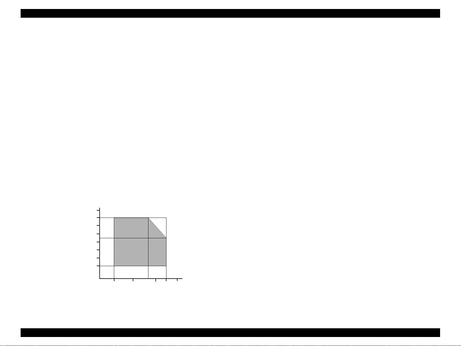
1.2.6 Environmental Condition
o Temperature
n Operating: 10 to 35°C (see the figure below for condition)
n Non-operating: -20 to 60°C (with shipment container)
1 month at 40°C and 120 hours at 60°C
o Humidity
n Operating: 20 to 80% RH
(without condensation / see the figure below for
condition)
n Non-operating: 5 to 85% RH
(without condensation / with shipment container)
o Resistance to Shock
n Operating: 1G, within 1 ms
n Non-operating: 2G, within 2 ms (with shipment container)
o Resistance to Vibration
n Operating: 0.15G
n Non-operating: 0.50G (with shipment container)
90
80
70
60
Humidity (%)
50
40
30
20
27
10
20
Temperature (°C)
30
35
40
1.2.7 Reliability
Total Print Volume: 75,000 pages (A4, Letter)
Print Head Life: 3 billion dots/nozzle
1.2.8 Safety Approvals
[120V Version]
Safety Standards: UL1950
CSA22.2 No.950
EMI: FCC part 15 subpart B Class B
CSA C108.8 Class B
[220∼240V Version]
Safety Standards: EN60950 (VDE)
EMI: EN55022 (CISPR Pub.22) Class B
AS/NZS 3548 Class B
1.2.9 Acoustic Noise
Level: Approx. 42dB(A) (According to ISO 7779)
-Used media : Plain Paper
- Print Quality: Fine
1.2.10 CE Marking
[220∼240V Version]
Low Voltage Directive 73/23/EEC: EN60950
EMC Directive 89/336/EEC: EN55022 Class B
EN61000-3-2
EN61000-3-3
EN50082-1
IEC801-2
IEC801-3
IEC801-4
Figure 1-1. Temperature/Humidity Range
PRODUCT DESCRIPTION SPECIFICATIONS 12
Page 13
EPSON Stylus COLOR 860/1160 Revision C
1.3 INTERFACE
The EPSON Stylus COLOR 860/1160 provide USB and parallel interface as
standard.
1.3.1 Parallel Interface (Forward Channel)
Transmission Mode: 8 bit parallel, IEEE-1284 compatibility mode
Synchronization: By STROBE pulse
Handshaking: BY BUSY and ACKNLG signal
Signal Level: TTL compatible level
Adaptable Connector: 57-30360 (amphenol) or equivalent
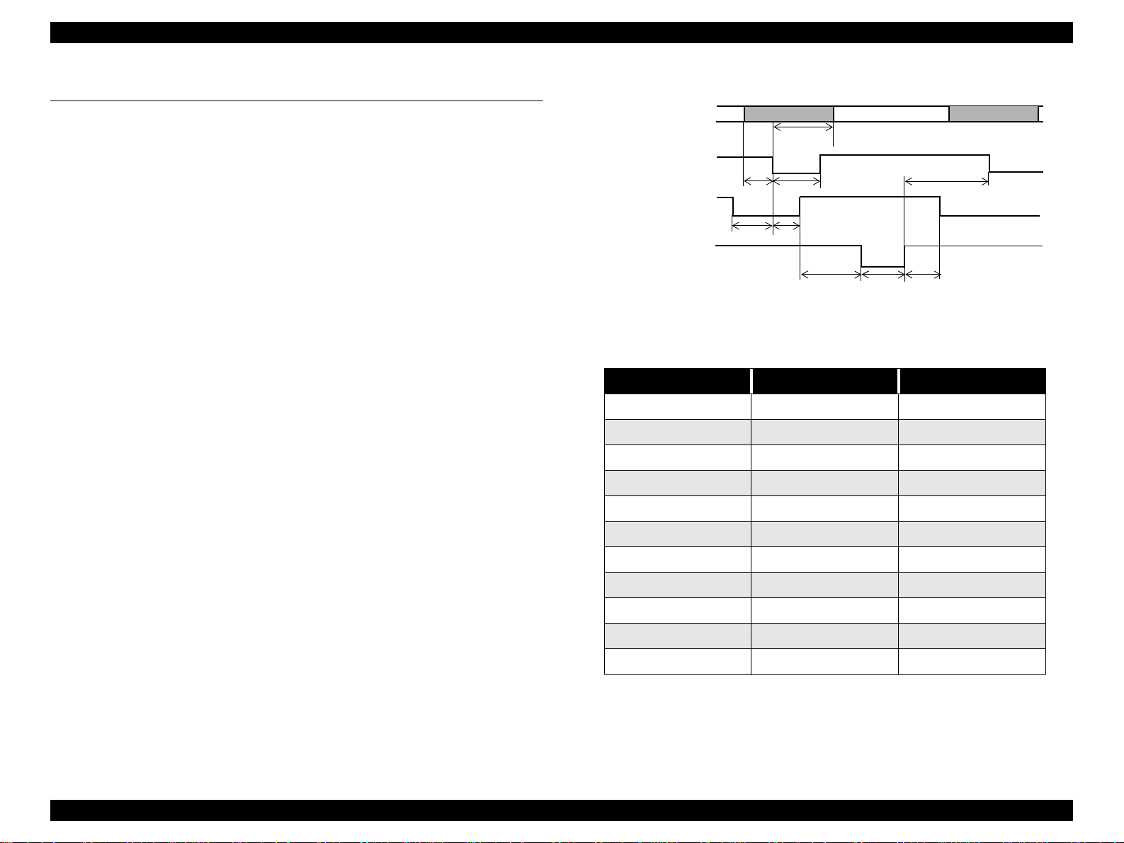
BUSY signal is set high before setting either -ERROR low or PE high, and held
high until all these signals return to their inactive state.
DATA
-STROBE
BUSY
-ACKNLG
data byte n
thold
tbusy
treply
tstb
tack
tnbusy
tsetup
tready
Figure 1-2. Data Transmission Timing
data byte n+1
tnext
BUSY signal is at high level in the following cases:
n During data entry (see data transmission timing).
n When input data buffer is full.
n During -INIT signal is at low level or during hardware initialization.
n During printer error (see -ERROR signal).
n When the parallel interface is not selected.
ERROR signal is at low level when the printer is in one of the following states:
n Printer hardware error (fatal error)
n Paper-out error
n Paper-jam error
n Ink-out error
PE signal is at high level during paper-out error.
Table 1-3.
Parameter Minimum Maximum
tsetup 500ns -
thold 500ns -
tstb 500ns -
tready 0 -
tbusy - 500ns
tt-out* - 120ns
tt-in** - 200ns
treply 0 -
tack 500ns 10us
tnbusy 0 -
tnext 0 -
* Rise and fall time of every output signal.
** Rise and fall time of every input signal.
*** Typical timing for tack is shown on the following page.
PRODUCT DESCRIPTION INTERFACE 13
Page 14
EPSON Stylus COLOR 860/1160 Revision C
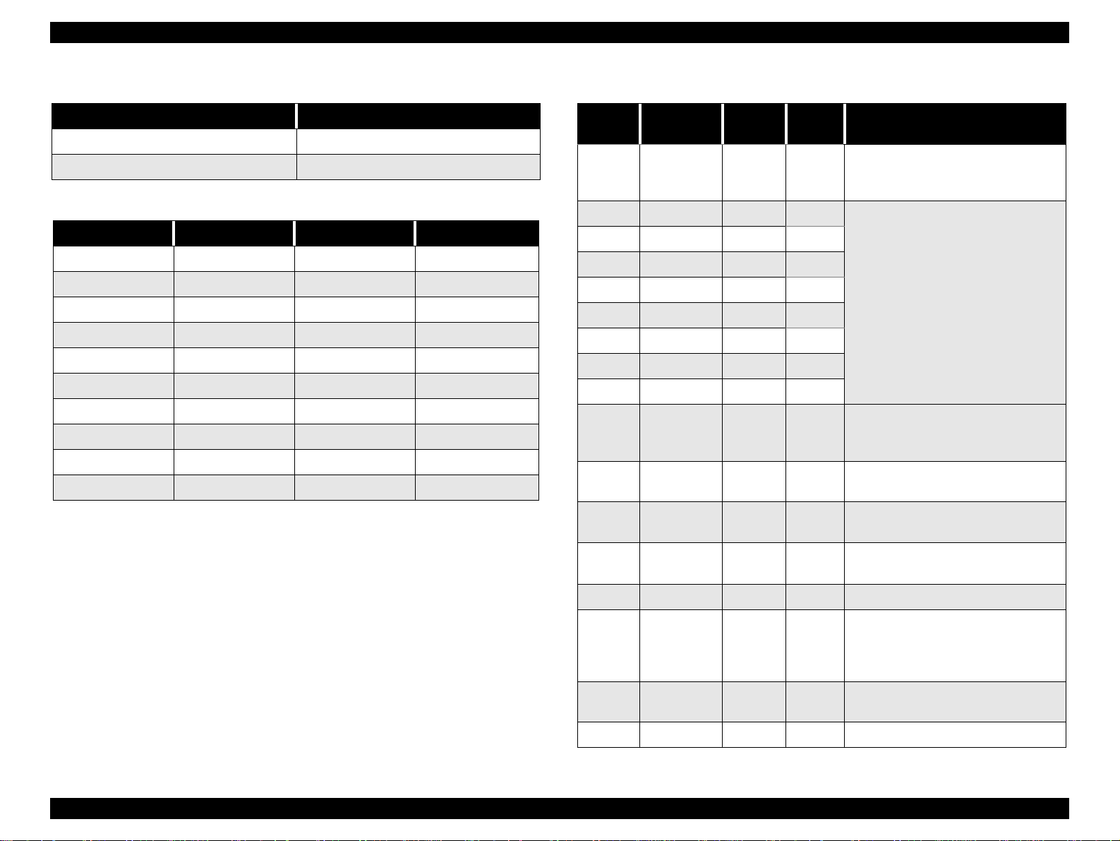
Table 1-4. Typical Time of tack
Parallel I/F Mode Typical Time of tack
High Speed 1us
Normal Speed 3us
Table 1-5. Signal Level: TTL Compatibl e (IEEE-1284 level 1 device)
Parameter Minimum Maximum Condition
VOH* - 5.5V
VOL* -0.5V -
IOH* - 0.32mA VOH = 2.4V
IOL* - 12mA VOL = 0.4V
CO - 50pF
VIH - 2.0V
VIL 0.8V -
IIH - 0.32mA VIH = 2.0V
IIL - 12mA VIL = 0.8V
CI - 50pF
* A low logic level on the Logic H signal is 2.0V or less when the printer
is powered off, and this signal is equal to or exceeding 3.0V when the
printer is powered on. The receiver shall provide an impedance
equivalent to 7.5K ohm to ground.
Table 1-6. Connector Pin Assignment and Signals
Pin No.
1 -STROBE 19 In
2 DATA0 20 In
3 DATA1 21 In
4 DATA2 22 In
5 DATA3 23 In
6 DATA4 24 In
7 DATA5 25 In
8 DATA6 26 In
9 DATA7 27 In
10 -ACKNLG 28 Out
11 BUSY 29 Out
12 PE 28 Out
13 SLCT 28 Out
Signal
Name
Return
GND Pin
In/Out Functional Descri ption
The strobe pulse. Read-in of data is
performed at the falling edge of this
pulse.
The DATA0 through DATA7 signals
represent data bits 0 to 7,
respectively.
Each signal is at high lev el when data
is logical 1 and low le vel whe n data is
logical 0.
This signal is a negative pulse
indicating that the printer can accept
data again.
A high signal indic ates that the printer
cannot receive data.
A high signal indicates paper-out
error.
Always at high level when the printer
is powered on.
14 -AFXT 30 In Not used.
The falling edge of a negative pulse
31 -INIT 30 In
32 -ERROR 29 Out
36 -SLIN 30 In Not used.
or a low signa l on this l ine c auses the
printer to initialize. Minimum 50us
pulse is necessary.
A low signal indicates printer error
condition.
PRODUCT DESCRIPTION INTERFACE 14
Page 15
EPSON Stylus COLOR 860/1160 Revision C
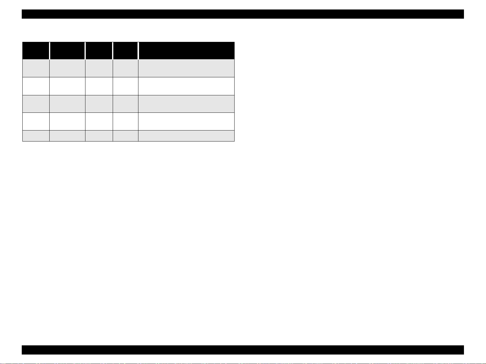
Table 1-6. Connector Pin Assignment and Signals (continued)
Pin No.
18 Logic H - Out
35 +5V - Out
17
16,33,
19-30
15,34 NC - - Not connected
Signal
Name
Chassis
GND
GND - - Signal GND
Return
GND Pin
- - Chassis GND
In/Out Functional Description
Pulled up to +5V via 3.9 K ohm
resistor.
Pulled up to +5V via 3.3K ohm
resistor.
NOTE: In/Out refers to the direction of signal flow seen from the printer
side.
PRODUCT DESCRIPTION INTERFACE 15
Page 16
EPSON Stylus COLOR 860/1160 Revision C
1.3.2 Parallel Interface (Reserve Channel)
Transmission Mode: IEEE-1284 nibble mode
Adaptable Connector See forward channel.
Synchronization: Refer to the IEEE-1284 specification
Handshaking: Refer to the IEEE-1284 specification
Data Trans. Timing: Refer to the IEEE-1284 specification
Signal Level: IEEE-1284 level 1 device
See forward channel.
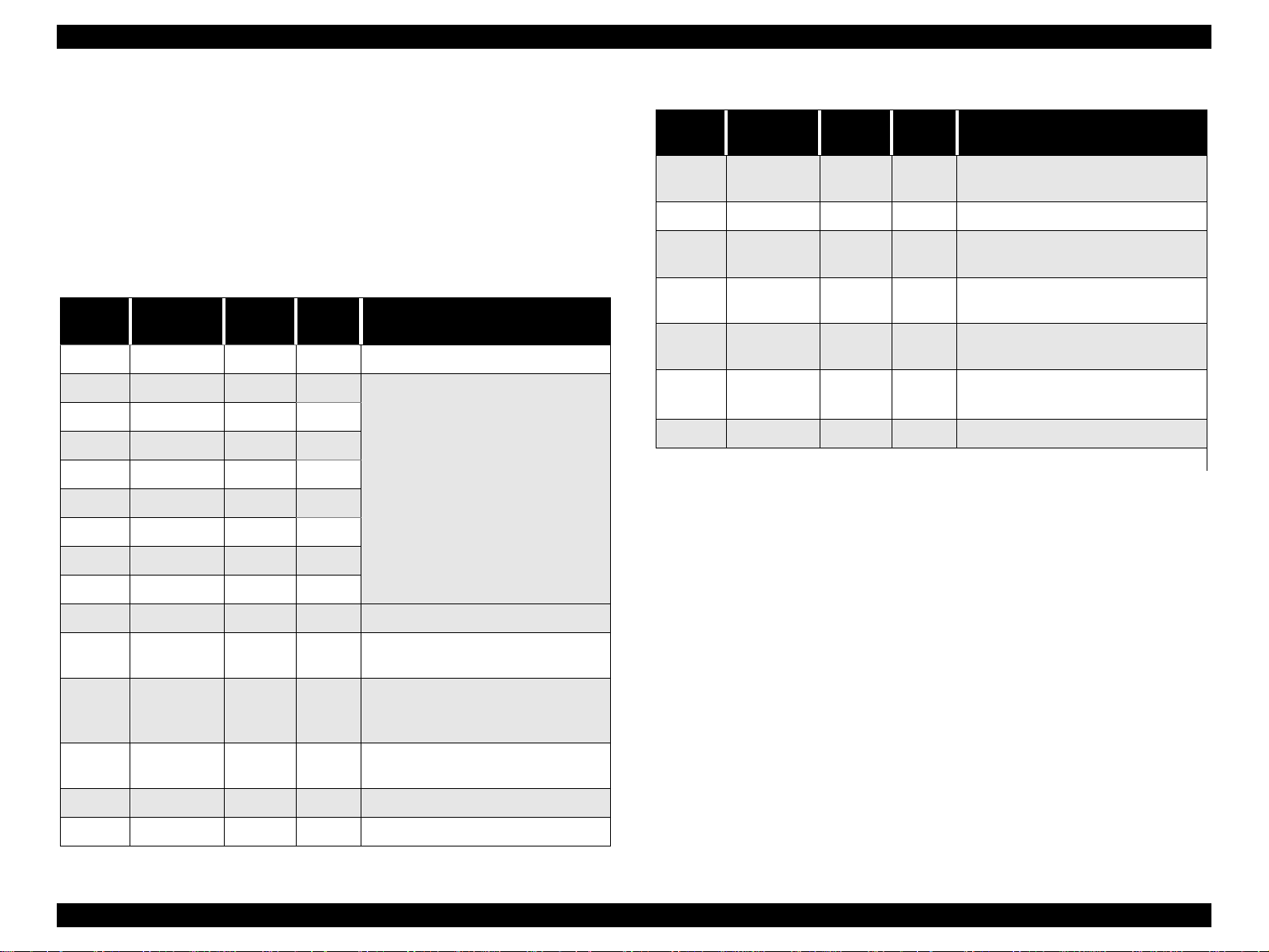
Table 1-7. Connector Pin Assignment and Signals
Pin No.
1 HostClk 19 In Host clock signal.
2 DATA0 20 In
3 DATA1 21 In
4 DATA2 22 In
5 DATA3 23 In
6 DATA4 24 In
7 DATA5 25 In
8 DATA6 26 In
9 DATA7 27 In
10 PtrClk 28 Out Printer clock signal.
11
Signal
Name
PtrBusy /
DataBit-3,7
Return
GND Pin
29 Out
In/Out Functional Description
The DATA0 through DATA7 signals
represent data bits 0 to 7,
respectively.
Each signal is at high level when data
is logical 1 and low level when data is
logical 0.
These signals are used to transfer
the 1284 extensibility request values
to the printer.
Printer busy signal and reverse
channel transfer data bit 3 or 7.
Table 1-7. Connector Pin Assignment and Signals (continued)
Pin No.
32
36 1284-Active 30 In 1284 active signal.
18 Logic-H - Out
35 +5V - Out
17
16,33,
19-30
15,34 NC - - Not connected
Note) In/Out refers to the direction of signal flow from the printer’s point of view.
Signal
Name
-DataAvail /
DataBit-0,4
Chassis
GND
GND - - Signal GND
Extensibility Request:
The printer responds affirmatively when the extensibility request values are
00H or 04H, which means,
00H: Request Nibble Mode Reverse Channel Transfer.
04H: Request Device ID;
Return Data Using Nibble Mode Rev Channel Transfer.
Return
GND Pin
29 Out
- - Chassis GND
In/Out Functional Description
Data available signal and reverse
channel transfer data bit 0 or 4.
Pulled up to +5V via 3.9K ohm
resistor.
Pulled up to +5V via 3.3K ohm
resistor.
12
13
14 HostBusy 30 In Host busy signal.
31 -INIT 30 In Not used.
AckDataReq
/ DataBit-2,6
Xflag /
DataBit-1,5
28 Out
28 Out
Acknowledge data request signal
and reverse channel tran sfer data bit
2 or 6.
X-flag signal and reverse channel
transfer data bit 1 or 5.
PRODUCT DESCRIPTION INTERFACE 16
Page 17
EPSON Stylus COLOR 860/1160 Revision C
Device ID:
The printer sends the following device ID string when requested.
When IEEE1284.4 is enabled,
[00H] [5AH] (for Stylus Color 860)
[00H] [5CH] (for Stylus Color 1160)
MFG: EPSON;
CMD: ESCPL2, BDC, D4;
MDL: Stylus[SP]COLOR[SP]860/1160;
CLS: PRINTER;
DES: EPSON[SP]Stylus[SP]COLOR[SP]860/1160;
When IEEE1284.4 is disabled,
[00H] [57H] (for Stylus Color 860)
[00H] [59H] (for Stylus Color 1160)
MFG: EPSON;
CMD: ESCPL2, BDC;
MDL: Stylus[SP]COLOR[SP]860/1160;
CLS: PRINTER;
DES: EPSON[SP]Stylus[SP]COLOR[SP]860/1160;
NOTE 1:[00H] denotes a hexadecimal value of zero.
NOTE 2:MDL value depends on the EEPROM setting.
NOTE 3:CMD value depends on the IEEE1284.4 setting.
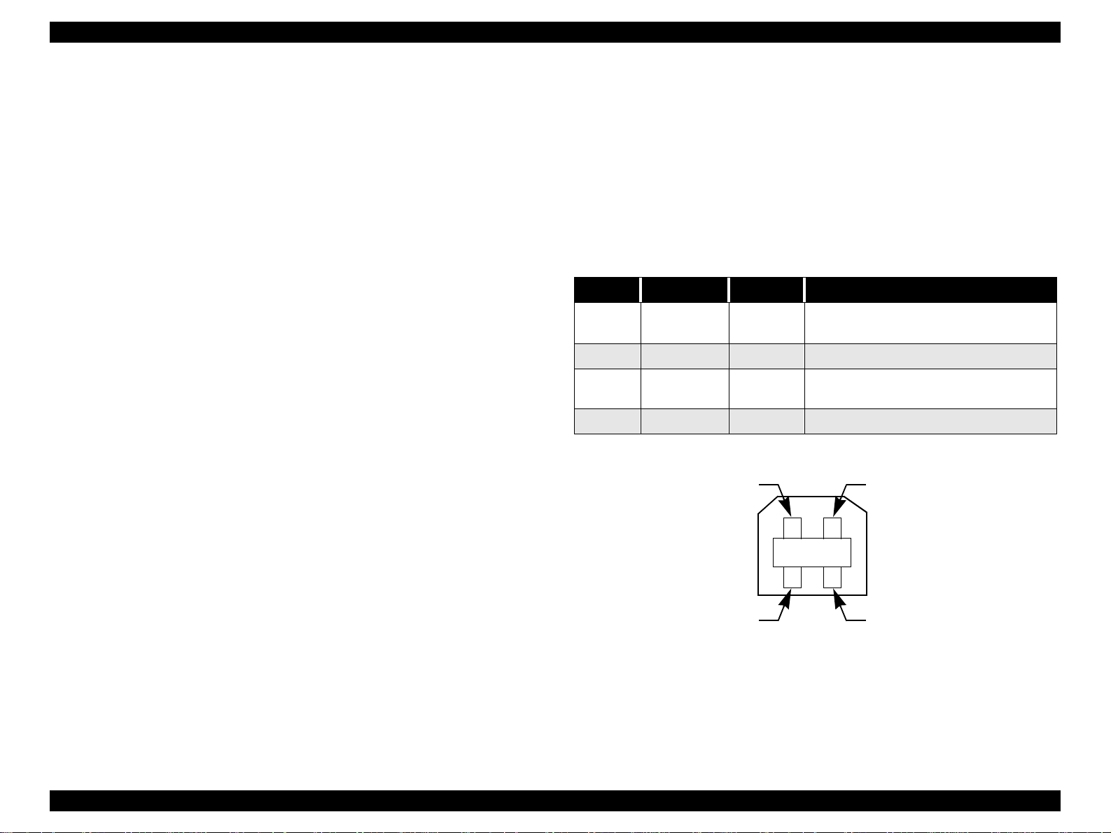
1.3.3 USB Interface
Standard: Based on:
“Universal Serial Bus Specifications Rev. 1.0”
“Universal Serial Bus Device Class Definition
for Printing Devices Version 1.0”
Bit Rate: 12Mbps (Full Speed Device)
Data Encoding: NRZI
Adaptable Connector: USB Series B
Recommended Cable Length: 2 meters
Table 1-8. Connector Pin Assignment and Signals
Pin No. Signal Name I/O Function Description
1VCC -
2 -Data Bi-D Data
3+DataBi-D
4 Ground - Cable ground
Pin #2
Cable power. Max. power consumption is
2mA.
Data, pull up to +3.3 V via 1.5K ohm
resistor.
Pin #1
Pin #3
Pin #4
Figure 1-3. USB Pin Assignment
PRODUCT DESCRIPTION INTERFACE 17
Page 18

EPSON Stylus COLOR 860/1160 Revision C
1.3.4 Prevention of Data Transfer Time-out
Generally, hosts abandon data transfer to peripherals when the peripheral is in
the busy state for dozens of seconds continuously. To prevent this kind of timeout, the printer receives data very slowly, several bytes per minute, even if the
printer is in the busy state. The slowdown starts when the remaining input
buffer becomes several hundreds of bytes, and the printer finally gets into the
busy state continuousl y when the input buffe r is full.
USB and IEEE1284.4 on the parallel interface do not require such function.
1.3.5 Interface Selection
The printer has two built-in interfaces: the USB and parallel interface.
These interfaces are selected automatically.
o Automatic Selection
In this automatic interface selection mode, the printer is initialized to the
idle state while scanning which interface receives data when it is powered
on. Then the interface which received data first is selected. When the host
stops data transfer and the printer is in the stand-by state for seconds, the
printer is returned to the idle state. As long as the host sends data or the
printer interface is in the busy state, the selected interface is let as it is.
o Interface State and Interface Selection
When the parallel interface is not selected, the interface gets into the busy
state. When the printer is initialized or returned to the idle state, the parallel
interface gets into the ready state. Note that the interrupt signal such as the
-INIT signal on the parallel interface is not effective while that interface is
not selected.
o Automatic Selection
An initial state is compatible interface and starts IEEE1284.4
communication when magic strings (1284.4 synchronous commands) are
received.
o On
An initial state is IEEE1284.4 communication and data that received it by
the time it is able to take synchronization by magic string (1284.4
synchronous commands) is discarded.
o Off
An initial state is compatible interface and never starts IEEE1284.4
communication even if magic strings (1284.4 synchronous commands) are
received.
1.3.6 IEEE1284.4 Protocol
The packet protocol described by IEEE1284.4 standard allows a device to
carry on multiple exchanges or conversations which contain data and/or control
information with another device at the same time across a single point-to-point
link. The protocol is not, however, a device control language. It does provide
basic transport-level flow control and multiplexing services. The multiplexed
logical channels are independent of each other and blocking of one has no
effect on the others. The protocol operates over IEEE1284.
PRODUCT DESCRIPTION INTERFACE 18
Page 19
EPSON Stylus COLOR 860/1160 Revision C
1.4 OPERATOR CONTROLS
1.4.1 Operating Switch
Operating switch is located on the control panel.
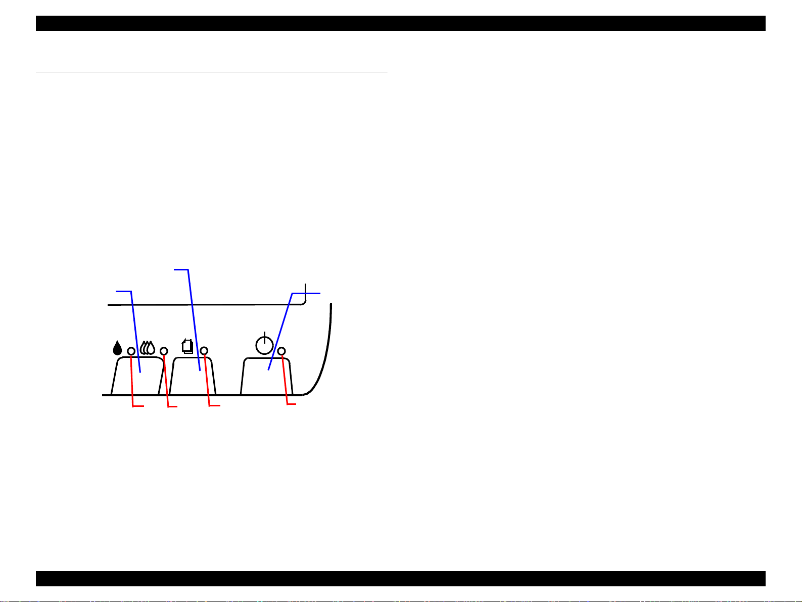
1.4.2 Control Panel
1.4.2.1 Switches
There are two non-lock type push switches, one lock-type push switch, and
four LED lights.
Load/Eject
Cleaning
Power
1.4.2.2 Indicators
(1) Power
Lights when the operating switch is “ON” and AC power is supplied.
(2) Paper Out
Lights during the paper-out condition, and blinks during the paper-jam
condition.
(3) Ink Out (Black)
Lights during no black ink condition, and blinks during the black
ink low condition.
(4) Ink Out (Color)
Lights during no color ink condition, and blinks during the color ink low
condition.
3
Figure 1-4. Control Panel
PRODUCT DESCRIPTION OPERATOR CONTROLS 19
4
2
1
Page 20
EPSON Stylus COLOR 860/1160 Revision C
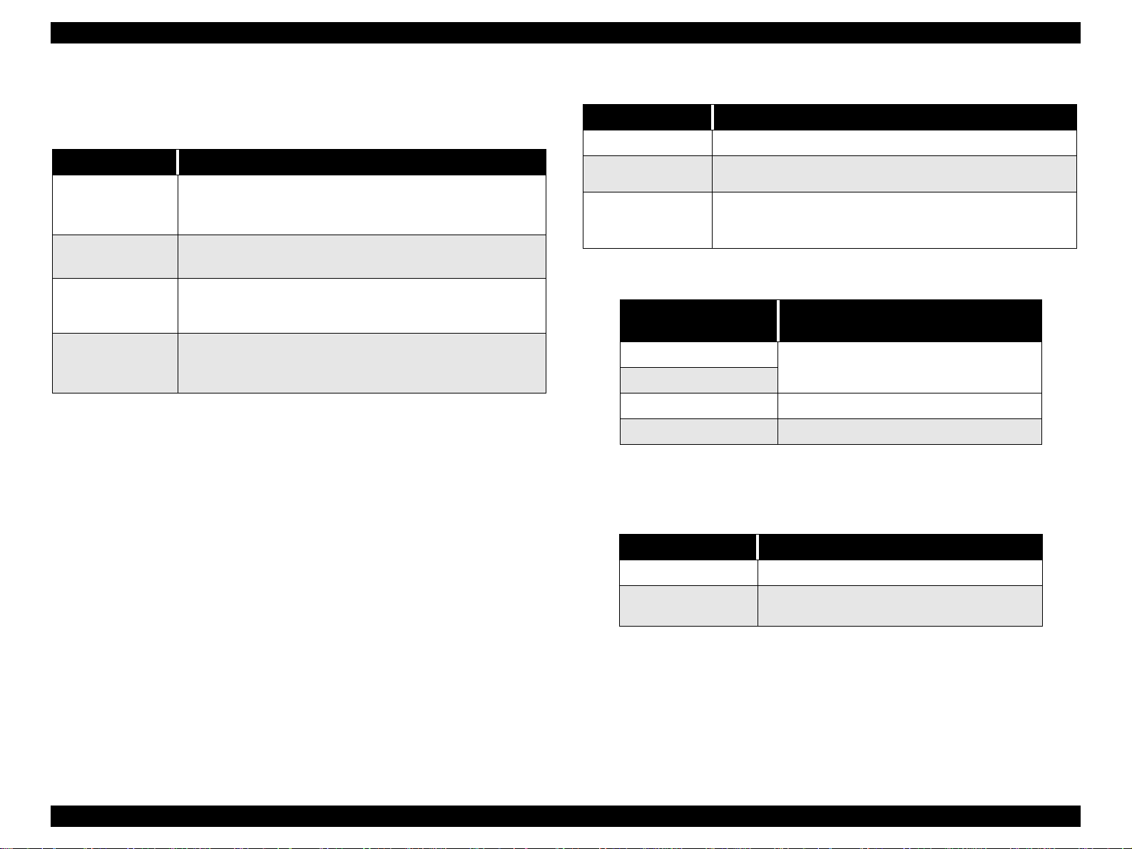
1.4.3 Panel Functions
Table 1-9. Panel Functions
Switch Function
Load / Eject
(Push for less than
2 sec.*)
Load / Eject
(Push for 2 sec.*)
Cleaning
(Push for 2 sec.*)
Cleaning
(Push for less than
2 sec.*)
* It is described in the user’s manual that three seconds are
required.
**This function is not available in printing status.
• Loads or ejects a paper.
• When the carriage is on the ink cartridge replacement
position, return the carriage to the capping position.
• Starts the ink cartridge replacement sequence.**
• Moves the carriage to the cartridge replacement position.
• Starts cleaning of the printhead.
• In the condition of “In k Low”, “Ink Out” , or “No I nk Cartridge ”,
starts the ink cartridge replacement sequence.**
• When the carriage is on the ink cartridge replacement
position, return the carriage to the capping position.
Table 1-10. Panel Function with Power On
Switch Pressing with Power On Function
Load / Eject
Cleaning
Load/Eject
+
Cleaning
*1: One of the following actions is carried out according to the content of
1BH of EEPROM.
Content of 1BH of
EEPROM, [bit7] [bit6]
*2: Not described in the user’s manual.
*3: See the table below.
• 1) Starts status printing. *1
• Changes code pages / Selec t IEEE1284.4 mode fo r parallel
I/F. *2
• Enters the special settings mode. (Factory use only). *3
Action
00
11
01 Start hex-dump printing.
10 Start self test printing.
Print firmware version, ink counter, selected
code page and nozzle check pattern.
Table 1-11. Special Setting Mode
Switch Function
Load / Eject
Cleaning
(Push for 10 seconds)
• Initialize EEPROM and reset timer IC.
• Reset the ink overflow counter in EEPROM.
PRODUCT DESCRIPTION OPERATOR CONTROLS 20
Page 21
EPSON Stylus COLOR 860/1160 Revision C
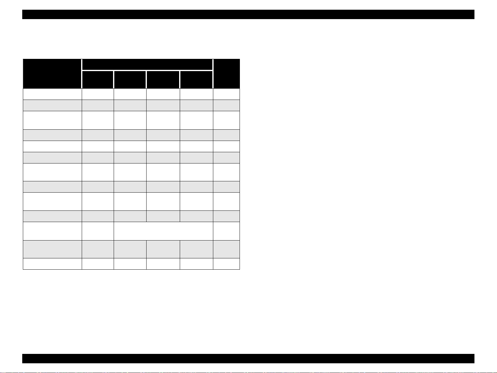
1.4.4 Printer Condition and Panel Status 1.4.5 Printer Initialization
Table 1-12. Printer Condition and LED Status
Indicators
Printer Status
Power On Condition On - - - 9
Ink Sequence Blink - - - 6
Ink Cartridge
Replacement Mode
Data Processing Blink - - - 8
Paper Out - - - On 4
Paper Jam Condition - Off Off Blink 3
No Ink Cartridge /
Ink End (Black)
Ink Level Low (Black) - Blink - - 7
No Ink Cartridge or
Ink End (Color)
Ink Level Low (Color) - - Blink - 7
Enter EEPROM and
Timer IC Reset
Maintenance
Request
Fatal Error Blin k On On Blink 1
Power
Blink - - - 5
-On- -7
--On-7
- ON (for 1 second only) -
Blink Blink Blink Blink 2
Ink Out
(Black)
Ink Out
(Color)
Paper Out
Priority
There are three kinds of initialization methods, and the following explains each
initialization.
1. Power-on Initialization
This printer is initialized when turning the pri nte r power on, or prin ter
recognized the cold-reset command (remote RS command).
When printer is initialized, the following actions are performed:
(a) Initializes printer mechanism.
(b) Clears input data buffer.
(c) Clears print buffer.
(d) Sets default values.
2. Operator Initialization
This printer is initialized when turning the printer power on again within 10
seconds from last power off, or printer recognized the -INIT signal
(negative pulse) of parallel interfac e.
When printer is initialized, the following actions are performed:
(a) Cap the printer head.
(b) Eject a paper.
(c) Clears input data buffer.
(d) Clears print buffer.
(e) Sets default values.
3. Software Initialization
The ESC@ command also initializ e the printer.
When printer is initialized, the following actions are performed:
(a) Clears print buffer.
(b) Sets default values.
PRODUCT DESCRIPTION OPERATOR CONTROLS 21
Page 22

EPSON Stylus COLOR 860/1160 Revision C
1.4.6 Errors
o Ink Out
When the printer runs out most of the ink of any color, it indicates ink-low
and keeps printing. When the printer runs out the whole ink of any color, it
stops printing and indicates ink-out error. User is then requested to install a
new ink-cartridge in this state. An ink-cartridge that has been taken out
once should never be used again. Re-installation of the cartridge not filled
fully upsets the ink level detection and may eventually cause a serious
problem in the print head.
o Paper Out
When the printer fails to load a sheet, it goes into a paper out error.
o Paper Jam
When the printer fails to eject a sheet, it goes into a paper jam error.
o No Ink-Cartridge
When the printer detects that ink-cartridge comes off, it goes into this error
mode.
o Maintenance Request
When the total amount of ink wasted through cleanings and flushing
reaches to the limit, printer indicates this error and stops. In such a case,
the absorber in the printer enclosure needs to be replaced with new one by
service personnel.
o Fatal Errors
Carriage control error or CG access error.
PRODUCT DESCRIPTION OPERATOR CONTROLS 22
Page 23

EPSON Stylus COLOR 860/1160 Revision C
1.5 PAPER
1.5.1 Paper Handling
Do not perform reverse feed more than 9.5mm (0.38”).
1.5.2 Paper Specification
1.5.2.1 Cut Sheet
[Size]
For Stylus Color 860/1160:
A4: Width 210mm (8.3”) x Length 297mm (11.7”)
Letter: Width 216mm (8.5”) x Length 279mm (11.0”)
B5: Width 182mm (7.2”) x Length 257mm (10.1”)
Legal: Width 216mm (8.5”) x Length 356mm (14.0”)
Statement: Width 139.7mm (5.5”) x Length 215.9mm (8.5”)
Executive: Width 184.2mm (7.25”) x Length 266.7mm (10.5”)
Photo Paper: Width 101.6mm (4”) x Length 152.4mm (6”)
For Stylus Color 1160 only:
A3: Width 297mm (11.7”) x Length 420mm (16.5”)
A3+: Width 329mm (13.0”) x Length 483mm (19.0”)
1.5.2.2 Transparency, Glossy Paper
[Size]
For Stylus Color 860/1160:
A4: Width 210mm (8.3”) x Length 297mm (11.7”)
Letter: Width 216mm (8.5”) x Length 279mm (11.0”)
For Stylus Color 1160 only:
A3+: Width 329mm x Length 483mm (Glossy Paper)
[Thickness]
0.075mm (0.003”) - 0.085mm (0.0033”)
*Transparency printing is available only at normal temperature.
1.5.2.3 Envelope
[Size]
No.10: Width 241mm (9 1/2”) x Length 104.8mm (4 1/8”)
DL: Width 220mm (8.7”) x Length 110mm (4.3”)
C6: Width 162mm (6.4”) x Length 114mm (4.5”)
[Thickness]
0.16mm (0.006”) - 0.52mm (0.02”)
[Thickness]
0.08mm (0.003”) - 0.11mm (0.004”)
[Weight]
2
64g/m
[Quality]
Exclusive paper, Bond paper, PPC
(17Ib.) - 90g/m2 (24Ib.)
[Weight]
45g/m2 (12Ib.) - 75g/m2 (20Ib.)
[Quality]
Bond paper, Plain paper, Air mail
Note1: Envelope printing is available only at normal temperature.
Note 2: Keep the longer side of the envelope horizontally at setting.
PRODUCT DESCRIPTION PAPER 23
Page 24

EPSON Stylus COLOR 860/1160 Revision C
1.5.2.4 In dex Card
[Size]
A6 Index Card: Width 105mm (4.1”) x Length 148mm (5.8”)
A5 Index Card: Width 148mm (5.8”) x Length 210mm (8.3”)
5 x 8” Index Card: Width 127mm (5.0” x Length 203mm (8.0”)
10 x 8” Index Card: Width 127mm (5.0”) x Length 203mm (8.0”)
[Thickness]
Less than 0.23mm (0.0091”)
PRODUCT DESCRIPTION PAPER 24
Page 25
EPSON Stylus COLOR 860/1160 Revision C
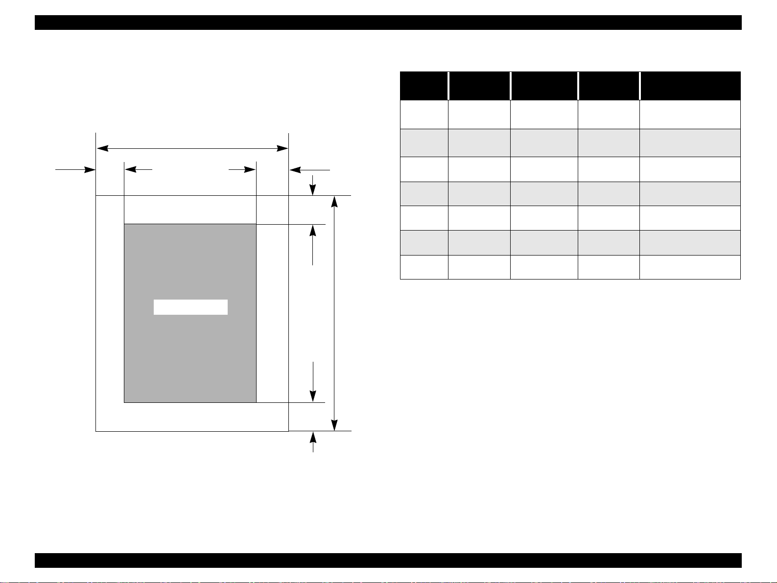
1.5.3 Printing Area
1.5.3.1 Cut Sheet
See the figure below and tables on the right for printable areas for Raster
Graphics mode and Character mode.
PW
LM
Printable Area
RM
TM
PL
Table 1-13. Character Mode
Paper
Size
A3 (*1) 3mm (0.12”) 3mm (0.12”) 3mm (0.12”)
A4 3mm (0.12”) 3mm (0.12”) 3mm (0.12”)
Letter 3mm (0.12”) 9mm (0.35”) 3mm (0.12”)
B5 3mm (0.12”) 3 m (0.12”) 3mm (0.12”)
Legal 3mm (0.12”) 9mm (0.35”) 3mm (0.12”)
Statement 3mm (0.12”) 3mm (0.12”) 3mm (0.12”)
Executive 3mm (0.12”) 3mm (0.12”) 3mm (0.12”)
Left Margin
(min.)
Right Margin
(min.)
Top Margin
(min.)
Bottom Margin
(min.)
14mm (0.54”) /3mm
(0.12”) (*2)
14mm (0.54”) /3mm
(0.12”) (*2)
14 mm (0.54”) / 3mm
(0.12”) (*2)
14 mm (0.54”) / 3mm
(0.12”) (*2)
14 mm (0.54”) / 3mm
(0.12”) (*2)
14 mm (0.54”) / 3mm
(0.12”) (*2)
14 mm (0.54”) / 3mm
(0.12”) (*2)
BM
Figure 1-5. Printable Area for Cut Sheet
PRODUCT DESCRIPTION PAPER 25
Page 26
EPSON Stylus COLOR 860/1160 Revision C
Table 1-14. Raster Graphics Mode
Paper
Size
A3* 3 mm (0.12”) 3 mm (0.12”) 3 mm (0.12”)
A3+* 3 mm (0.12 ”) 3 mm (0.12”) 3 mm (0.12”)
A4 3 mm (0.12”) 3 mm (0.12”) 3 mm (0.12”)
Letter 3 mm (0.12”) 3 mm (0.12”) 3 mm (0.12”)
B5 3 mm (0.12”) 3 mm (0.12”) 3 mm (0.12”)
Legal 3 mm (0.12”) 3 mm (0.12”) 3 mm (0.12”)
Statement 3 mm (0.12”) 3 mm (0.12”) 3 mm (0.12”)
Exclusive 3 mm (0.12”) 3 mm (0.12”) 3 mm (0.12”)
* For Stylus Color 1160 only.
** Bottom margin can be reduced to 3mm when paper dimension is
*** Refer to 1.5.2 Paper Specification for PW (paper width) and PL
Left Margin
(min.)
Right Margin
(min.)
Top Margin
(min.)
Bottom Margin
(min.)
14 mm (0.54”) / 3mm
(0.12”) **
14 mm (0.54”) / 3mm
(0.12”) **
14 mm (0.54”) / 3mm
(0.12”) **
14 mm (0.54”) / 3mm
(0.12”) **
14 mm (0.54”) / 3mm
(0.12”) **
14 mm (0.54”) / 3mm
(0.12”) **
14 mm (0.54”) / 3mm
(0.12”) **
14 mm (0.54”) / 3mm
(0.12”) **
defined by using command, otherwise it is not reduced (14mm). As for
an area between 3mm and 14mm margin, printing quality may decline.
(paper length).
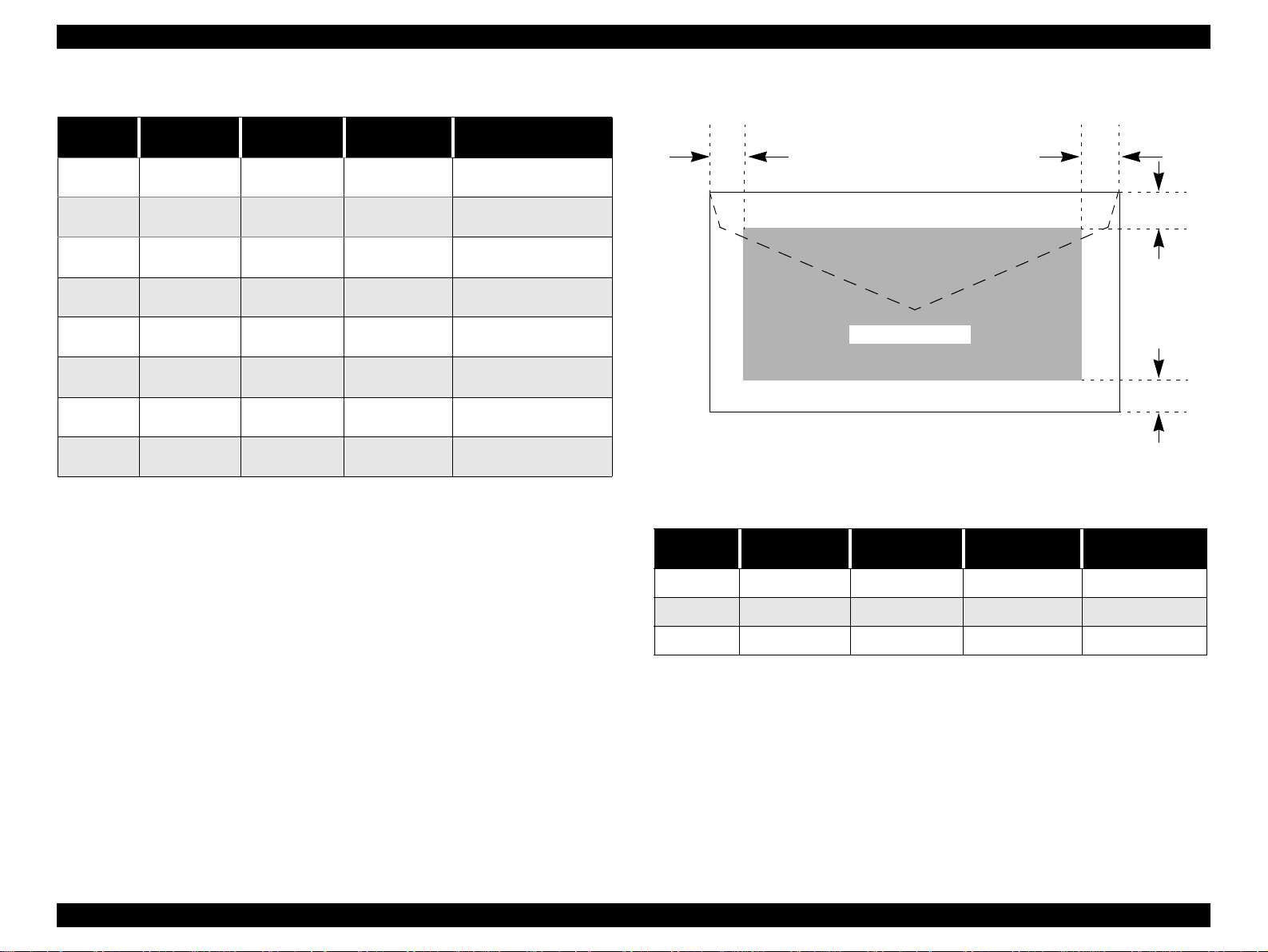
1.5.3.2 Envelopes
LM
Printable Area
Figure 1-6. Printable Area for Envelopes
Table 1-15. Envelope Margin
Size
#10 3 mm (0.12”) 28 mm (1.10”) 3 mm (0.12”) 14 mm (0.55”)
DL 3 m m (0.12”) 7 mm (0.28”) 3 mm (0.12”) 14 mm (0.55”)
Left Margin
(min.)
Right Margin
(min.)
Top Margin
(min.)
Bottom Margin
RM
TM
BM
(min.)
C6 3 mm (0.12”) 3 mm (0.12”) 3 mm (0.12”) 14 mm (0.55”)
PRODUCT DESCRIPTION PAPER 26
Page 27
EPSON Stylus COLOR 860/1160 Revision C
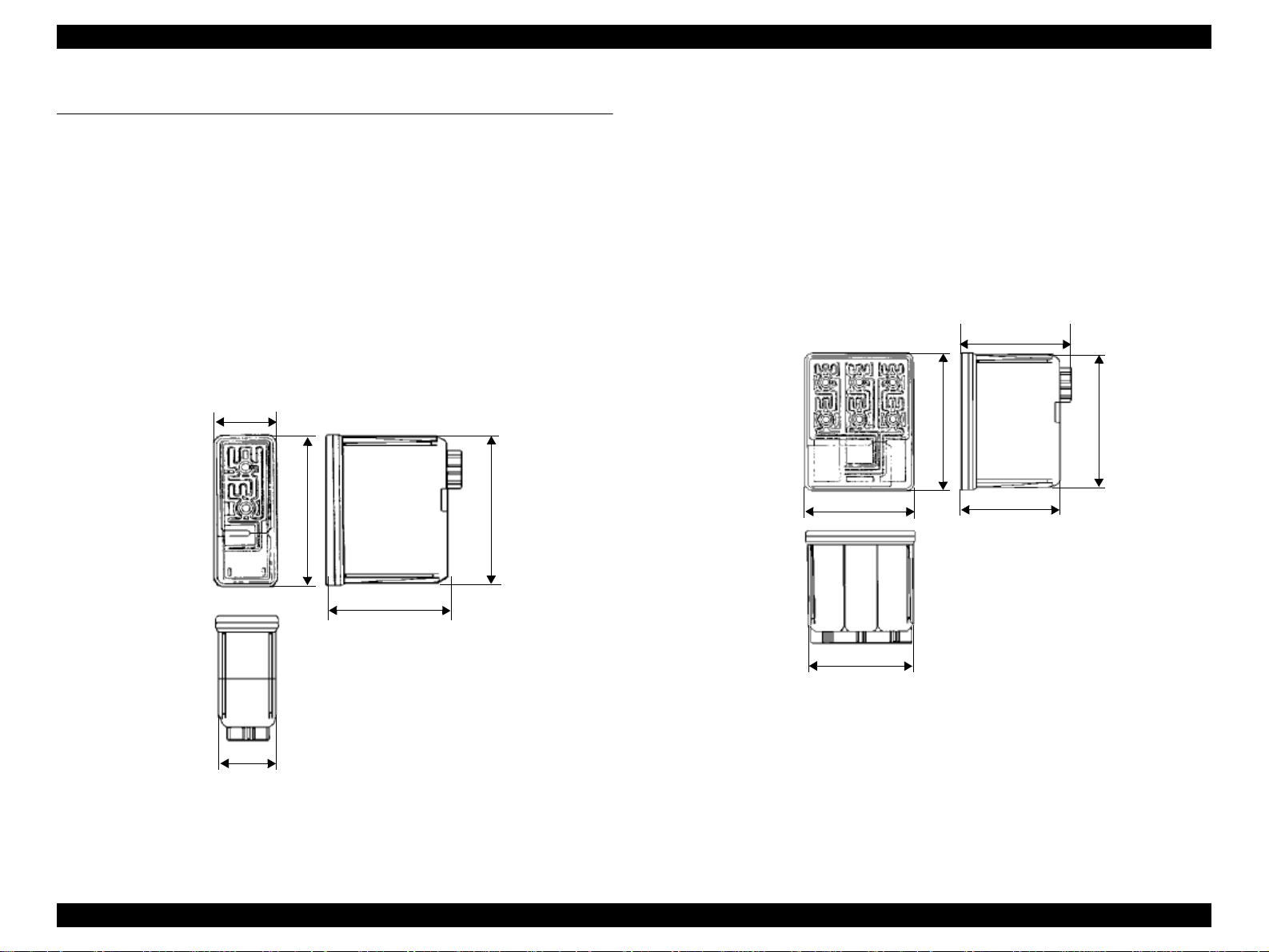
1.6 INK CARTRIDGE
1.6.1 Black Ink Cartridge
Type: Exclusive Cartridge
Color: Black
Print Capacity: 900 pages/A4
(ISO/IEC 10561 Letter Pattern at 360 dpi)
Ink Life: 2 years from date of production
Storage Temperature:
Storage: -20
Packing: -30
Transit: -30
Dimension: 27.8 mm (W) x 52.7 mm (D) x 38.5 mm (H)
27.8
o
C to 40 oC (within a month at 40 oC)
o
C to 40 oC (within a month at 40 oC)
o
C to 60 oC (within 120 hours at 60 oC
and within a month at 40
52.7
o
C)
51.2
1.6.2 Color Ink Cartridge
Type: Exclusive Cartridge
Color: Magenta, Cyan, Yellow
Print Capacity: 300 pages / A4 (360 dpi, 5% duty each color)
Ink Life: 2 years from date of production
Storage Temperature:
Storage: -20
Packing: -30
Transit: -30
Dimension: 42.9 mm (W) x 52.7 mm (D) x 38.5 mm (H)
o
C to 40 oC (within a month at 40 oC)
o
C to 40 oC (within a month at 40 oC)
o
C to 60 oC (within 120 hours at 60 oC
and within a month at 40
52.7
42.9
43.2
38.5
o
C)
51.2
38.5
41.4
Figure 1-8. Color Ink Cartridge
26.3
Figure 1-7. Black Ink Cartridge
Note 1: Ink cartridge can not be refilled. The ink cartridge is prepared only
for article of consumption.
Note 2: Do not use the ink cartridge which contains life-expired ink.
Note 3: Ink will be frozen under -4
o
C environment; however, it will be
usable after being left at room temperature for more than three
hours.
PRODUCT DESCRIPTION INK CARTRIDGE 27
Page 28

OPERATING PRINCIPLES
CHAPTER
Page 29
EPSON Stylus COLOR 860/1160 Revision C
2.1 Overview
This section describes the operating principles of the printer mechanism and
electrical circuit boards. The EPSON Stylus COLOR 860/1160 has the
following boards:
o
Main board: C298MAIN Board (Stylus COLOR 860/1160)
o
Power supply board: C298PSB/PSE Board (Stylus COLOR 860/1160)
o
Panel board: C298PNL Board (Stylus COLOR 860)
C304PNL Board (Stylus COLOR 1160)
2.1.1 Printer Mechanism
Unlike other EPSON ink jet printers, the
motor for power source. Use of the DC motor enable the printer to lower noise
during printing to a great extent. Table 2-1 shows the various motor types used
in the printer and their applications.
Table 2-1. Motor Types and Corresponding Applications
Motor Name Type Application / Feature
CR Motor DC with brush
PF Motor DC with brush
Pump/ASF
4-Phase 48-pole
stepping motor
Stylus COLOR 860/1160
Used to drive the carriag e maki ng littl e noise . A
a linear scale is used to monitor the motor’s
operating condition.
• Drives paper feeding rollers used to send
paper at specified speeds and load/eject
paper.
• CR lock lever operation
• To monitor paper feeding pitch, a loop scale
is attached beside the high-precision gear.
Like the Stylus COLOR 800 and Stylus Pro
5000, this motor manages pump drive and
paper loading from ASF.
Since this is a stepping motor, it has no scales
or photo sensors that are used to monitor the
motor’s operating condit ion .
uses DC
The basic structure of the printer mechanism is mostly common to the Stylus
COLOR 400/600/440/640/740, except that the Stylus COLOR 860/1160 uses a
Pump/ASF motor. With this motor equipped, the paper loading mechanism and
the pumping mechanisms are independently driven, which allows the printer to
offer higher throughput as a result.
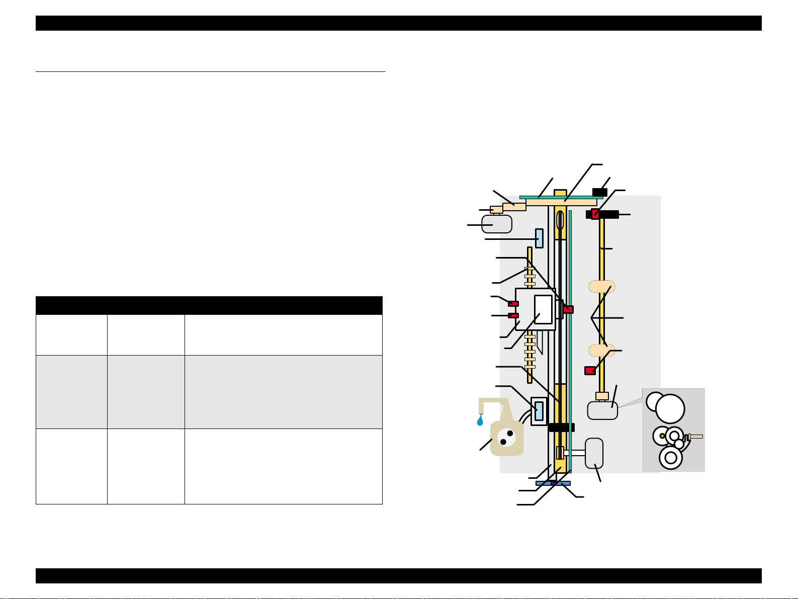
Figure 2-1 shows the printer mechanism block diagram for the Stylus COLOR
860/1160.
Loop Scale
Plain Gear
PF Motor Pinion
PF Motor
Flashing Window
(at 80th or 136th column)
Photo Interrupter
(Encoder for CR)
Star Wheel Roller
Bk I/C Sensor
CMY I/C Sensor
Carriage Unit
Printhead (one unit)
Timing Belt
Cap Unit
(without a valve)
Pump Unit
CR Guide Shaft
PF Roller
Liner Scale
PF Drive Gear
Encoder (PF)
ASF Sensor
Detector Wheel
Loading Shaft
Loading Rollers
PE Sensor
Pump/ASF Motor
(stepping motor)
CR Motor (DC motor)
PG Lever
Figure 2-1. Printer Mechanism Block Diagram
Operating Principles Overview 29
Page 30
EPSON Stylus COLOR 860/1160 Revision C
2.1.1.1 P rinting Mechanism
The basic operating principles of the printhead, which plays a major role in
printing, are the same as previous models; ones that use a on-demand type UCHIP head method. (Refer to Figure1-1.)
Also, unlike the Stylus Color IIs, 820 and 200, the Stylus COLOR 860/1160 is
not an automatic correction type. So, in order to correct dispersion of multi
layer piezo electric element that drives each nozzle, you are required to input a
VH value written on the top surface of the printhead by using an exclusive
program when you replace the printhead, control board, or printer mechanism.
(Note there are no resistor arrays to determine the VH voltage on the main
control board.) Following explains printhead.
o PZT
PZT is an abbreviation of Piezo Electric Element. Print signals from the
Main board are sent through the driver board on the printhead unit to the
PZT. Then, the PZT pushes the top cavity whic h has ink sto red to
discharge the ink from each nozzle on the nozzle plate.
o Cavity Set
The ink absorbed from the ink cartridge goes through the filter and then is
stored temporarily in this tank called “cavity” until PZT is driven.
I/C Sensor Actuator
Nozzle Plate
PZT
Nozzle Selector Board
Ink Cartridge
Needle
Filter
Cavity
o Nozzle Plate
Figure 2-2. Printing Mechanism
The board with nozzle holes on the printhead surface is called Nozzle
Plate.
o Filter
When the ink cartridge is installed, if any dirt or dust around the cartridge
needle is absorbed into the head, there is a great possibility of causing
nozzle clog and disturbance of ink flow, and finally causing alignment
failure and dot missing. To prevent this problem, a filter is set below the
cartridge needle, where ink is filtered.
Operating Principles Overview 30
Page 31

EPSON Stylus COLOR 860/1160 Revision C
2.1.1.2 P rinting Pro cess
Figure 2-3 and Figure 2-4 show the normal state and ejecting state of the
printhead, respectively.
1. Normal State:
When the print signal is not output, PTZ also does not move from a waiting
state (normal state). (Refer to Figure 2-3.)
2) Ejecting Stat e:
When the print signal is output from the C298MAIN board, IC (IR4C463S:
Nozzle Selector) located on the printhead unit latches data once by 1-byte
unit. An appropriate PZT latched by the nozzle selector is pushed into the
cavity by the common voltage applied from the main board. By this
operation, ink stored in the cavity spurts out from nozzles. (Refer to Figure
2-4.)
Ink Course Cavity
Figure 2-3. Print Head Normal State
PZT
Nozzle
Nozzle Plate
Figure 2-4. Print Head Ejecting State
Operating Principles Overview 31
Page 32

EPSON Stylus COLOR 860/1160 Revision C
2.1.1.3 Carria ge Mechanism
The carriage mechanism for the Stylus COLOR 860/1160 is mostly the same
as for other ink jet printers except it is driven by a DC motor. See the table
below for the carriage motor specifications.
Table 2-2. Carriage Motor Specification
Items Specifications
Type DC Motor with brush
Drive Voltage +42 V +/- 5%(DRV IC voltage)
Internal Resistance 29.2 ohms +/- 25%
Inductance 30.8 mH +/- 25%
Drive Method Constant Current Chopping
Driver IC LB1947
Unlike a stepping motor, the DC motor that drives the carriage can not detect
the current carriage position by referring to the pulses given. Therefore, a linear
scale is attached along the carriage operation range to enable the printer to
mechanically detect the carriage position. The linear scale is also used to
produce the print timing signal (PTS signal), to which the printer refers to for a
correct ink ejection timing.
For detailed information on the CR motor control circuit, see Section 2.2.
Carriage Motor
PF Roller
Timing Belt
Carriage Unit
Front Side
Rear Side
Parallelism
Adjust Lever
The printhead, a core of the printing mechanism, is stored in the carriage unit.
When the adjustment lever is moved up and down, this printhead is maintained
tilt in a flexible and adjustable structure by the tilt adjustment mechanism.
Also, the parallelism adjustment levers, mounted on the left and right sides of
the carriage guide shaft, are used to set the carriage guide shaft parallel to the
platen when the shaft has been installed to the printer mechanism. After this
adjustment is completed, moving the PG adjustment lever sets the distance
between the platen surface and the printhead surface to one of two
possibilities: 1.14 mm or 1.84 mm. Moving the PG lever, you can rotate the
shafts of the carriage guide shaft which itself is decentralized to change the
distance. This is the mechanism that the user can use to adjust the appropriate
PG value according to the printing result or any other environmental conditions
such as thick paper.
Fixing
Bushing
Carriage
Guide Shaft
Eject Roller
Paper Guide (Front)
PF Motor
CR Lock Lever
Figure 2-5. Carriage Mechanism (Top view)
Operating Principles Overview 32
Page 33

EPSON Stylus COLOR 860/1160 Revision C
2.1.1.4 Platen Gap (PG) Adjust Mechanism
The PG adjustment, at the left of the printer mechanism, consists of the PG
lever, PF support lever, right/left parallelism adjustment levers, and CR guide
shaft. The PG adjustment mechanism is designed to keep the platen gap
correct for the paper thickness to prevent ink from smearing. The PG lever
joins the CR guide shaft, which has an eccentricity via PG sub lever. Switching
the lever from “0” to “+” rotates the CR shaft and changes the platen gap from
narrow to wide.
Table 2-3. Platen Gap Adjust Lever Setting
Paper Lever Position PG adjustment value
All Media Front
If you find any print
problems or use thick
paper.
Rear
0 mm
(1.14 mm between head and platen)
0.7mm
(1.84 mm between head and platen)
2.1.1.5 Paper Feeding Mechanism
The paper feeding mechanism transports paper loaded from ASF using the PF
rollers and paper eject rollers. A new type of DC motor is used for the PF
motor. See the table below for the DC motor specifications.
Table 2-4. PF Motor Specifications
Item Description
Motor type DC Motor with Brush
Drive voltage +42V +/- 5% (DRV IC voltage)
Coil Resistance 31.1 ohm +/- 25%
Drive frequency [Hz] 26.6mH +/- 25%
Control method A3958
Unlike a stepping motor, the DC motor that drives the paper feeding
mechanism can not measure the paper feeding amount by referring to the
pulses given. For this reason, the loop scale and encoder sensor are directly
attached to the left end of the PF roller shaft to mechanically control paper feed
amount. See Section 2.2 for detailed information on the PF motor control
circuit.
Drive from the PF motor is sent to the PF rollers and paper eject rollers as
described below.
o To the PF rollers:
PF motor pinion gear
→ Spur gear (76) → PF rollers
o To the eject rollers:
PF motor pinion gear
Spur gear (28)
Figure 2-6 in the next page gives the paper feeding mechanism block diagram,
showing the parts along the PF motor drive transmission paths.
→ Spur gear (76) → Combination gear (13.5, 308) →
→ Paper eject rollers
Operating Principles Overview 33
Page 34

EPSON Stylus COLOR 860/1160 Revision C
Front Paper Guide
Eject Roller
PF Motor
Figure 2-6. Paper Feeding Mechanism
The printer loads paper at the ASF, which is detected by the PE sensor
attached to the right side of the top frame, and advances it to send the paper’s
leading edge to the halfway of the front paper guide. Then, to correct
deflection, the printer feeds the paper back specified steps toward ASF, and
advances the paper again toward the front paper guide and stops it at the
specified TOF (Top Of Form) position. Once the printer starts printing, it
transports paper using the PF rollers and sub rollers, and as the printer
transports or printing on the tailing 14 mm, it uses a star wheel gear and paper
eject rollers. Like the Stylus COLOR 440/640/740, this printer also provides
this extra printable range of 14 mm from the bottom edge, excluding the bottom
margin of 3mm, by changing the position of the star wheel gear; it has been
shifted by 5
this change, the tailing edge of paper is suppressed, and the printer can
advance paper steadily when printing around the bottom area. See Figure 2-7
next page that shows how paper is transported and parts involved.
° from the top of the eject roller toward the front paper guide. Due to
[Previous Models]
Star Wheel Assy.
Paper
Eject Roller
Printhead
Platen
[Stylus COLOR 860/1160]
Five Degrees
Figure 2-7. Paper Transportation
Support Roller
Bottom margin 3 mm touch es
the printhead surface.
Steady
PF Roller
Operating Principles Overview 34
Page 35

EPSON Stylus COLOR 860/1160 Revision C
2.1.1.6 CR Lock Mechanism
The carriage lock mechanism prevents the carriage from being left at an
uncapped position for a long time, which is usually caused by vibration during
printer transportation, user’s mishandling of the printer, and so on.
The CR Lock mechanism is driven with the DC PF motor. For the motor
specifications, refer to the Table 2-4 . The PF motor drive is used for the Paper
Feed Mechanism also and the CR lock mechanism is controled depends on
the direction of the PF motor rotationa. The CR lock mechanism is assembed
on the right tip of the Paper Eject Roller as shown in the folloiwng figure.
Top view
Bushing 6
Paper Eject Roller
Figure 2-8. CR Lock mechanism
CR Lock Lev e r
Middle Frame
Right side view
CR unit
CR unit
The carriage lock mechanism prevents the carriage from being left at an
uncapped position for a long time, that is usually caused by vibration during
printer transportation, user’s mishandling of the printer, and so on. If the
carriage is left uncapped for a long time, ink on its surface will become
gradually thick and not spurt from the nozzles as a result.
To make matters worse, the holes (crater) of the nozzles may be completely
clogged by the thick ink, and they may not be able to return to a normal
condition just by a cleaning operation. To prevent this, the printer enters a
carriage lock condition in the foll owi ng condi tio ns .
o After Power-off operation:
If the printer power is turned off in the middle of printing or any other
performances, carriage lock takes place in the end after an initialization
operation.
o After Power-on operation:
After the printer power is turned on and an automatic power-on cleaning is
completed, carriage lock is performed. The power-on cleaning is an
automatic head cleaning that runs when the printer power is turned on. The
timer IC always calculates printer’s power off time using power from a
lithium battery mounted on the C298MAIN board. The power-on cleaning
function automatically selects a correct cleaning level according to the
length of time which the printer has been turned off.
o After ejecting paper:
After the Load/Eject button is pressed and the paper is ejected, if the
printer does not receive any data, it performs carriage lock and goes to a
standby state. However, if paper is loaded by pressing the Load/Eject
button, the printer does not perform the ca rria ge loc k opera tio n.
While the PF motor drive is used for paper feeding (PF motor rotation: CCW),
the CR Lock lever is set under the Paper Eject Frame, but the CR Lcok lever
rises up with clockwise rotation of the PF motor and locks the CR unit.
Drive from the PF motor is sent to the CR Lock lever via Papaer Eject Roller as
described below.
To the CR lock lever
PF motor pinion gear (CW rotation)
(13.5, 30.8)
→ Spur gear (28) → Paper eject rollers→ CR lock lever
→ Spur gear (76) → Combination gear
PF motor torque is always transmitted to the CR lock lever side, but the
operation of the CR lock mechanism varies depending on the rotational
direction of the PF motor, as shown in the table below.
Table 2-5. CR lock mechanism & PF rotational direction
Directions Corresponding Functions
Counterclockwise
ckwise
• Release the CR lock lever.
• Sets the CR lock lever.
Operating Principles Overview 35
Page 36

EPSON Stylus COLOR 860/1160 Revision C
2.1.1.7 Paper Loading Mechanism
The paper loading mechanism loads paper at the ASF unit and feeds paper to
the PF rollers. The ASF unit, the same as in the Stylus COLOR 440/640/740,
uses a 4-phase 48-pole PM type stepping motor for the ASF/Pump motor.
Drive sent from this motor is switched between the ASF unit side and pump
unit by the disengage mechanism. See Figure 2-6 for the ASF/Pump motor
specifications.
Table 2-6. ASF/Pump Motor Specifications
Items Description
Motor type 4 Phase/ 48-pole /PM type pulse motor
Drive method Bipolar drive
Drive voltage +42V +/- 5% (DRV IC voltage)
Coil Resistance 10.4 ohm +/- 10%
Drive frequency [Hz] 15mH
Control method A3958
The rotational directions and their functions are shown in the table below:
Table 2-7. ASF/Pump Motor Rotation
Torque from the ASF/Pump motor is transmitted to the ASF as described
below:
o Torque transmission to the ASF unit
1) When the CR unit moves to the right end of the CR shaft, the DE lock lever
is pushed to the right end.
2) The ASF-Pump motor rotates clockwise specified steps (viewed from the
motor pinion gear side).
3) With the rotation of step 2), the planetary gear set in the disengage unit
shifts to the combination gear (12, 22.4) side.
4) The CR unit moves specified steps from the right end of the CR shaft to the
left. With this movement, the DE lock leve r fixes the planetary gear unit.
5) Torque from the ASF/Pump motor is transmitted as described below.
Motor pinion gear → Planetary gear (15.2) → Combination gear (12,
22.4)
→ Combination gear (14, 28) → Spur gear (32) in ASF
Figure 2-9 shows the disengage mechanism and the parts involved.
C om bination G ear 14,28
C om bination G ear 12,22.4
Planetary gear 15.2 unit
A
D E Lock Lever
Directions Corresponding Functions
Clockwise
Counterclockwise
• Sets the paper return lever.
• Switches torque to the ASF side.
• Loads paper at ASF.
P in io n fo r
AS F/Pum p M otor
: P aper loading rotation
C om bination G ear 17.19,25.6
: A S F s id e s w itc h ro ta tio n
Figure 2-9. Disengage Mechanism
Operating Principles Overview 36
Page 37

EPSON Stylus COLOR 860/1160 Revision C
Torque sent from the ASF/Pump motor to the ASF unit via the disengage
mechanism is used for the following operation.
o Paper loading operation
Like the Stylus COLOR 440/640/740, ASF of this printer has the multiple paper
loading prevention mechanism to provide steady paper loading. This
mechanism prevents a sheet of paper from falling from the paper set
position into the paper path. A paper return lever in the mechanism pushes
paper that may have fallen off back onto the hopper. After this motion is
completed, the LD roller starts loading paper. The paper loading
mechanism, including the multiple paper loading prevention mechanism, is
described in the following steps.
LD Roller
Hopper Hopper Spring
Cam
1. When the printer power is turned on, the ASF/Pump motor rotates
counterclockwise to detect ASF home position. Then the motor rotates
clockwise specified steps to set the LD roller and paper turn lever in place.
(See “Standby State” in Figure 2-10.)
2. When the paper loading signal is sent from the PC and the Load/Eject
button is pressed, ASF/Pump motor turns counterclockwise to let the LD
roller load paper. (See “Paper Pick Up State” in Figure 2-10.)
3. When the paper is transported to the PF roller, the LD roller stops where it
loses friction. (See “PF Roller Paper Feed State” in Figure 2-10.)
4. When the next print signal is sent and Load/Eject button is pressed, the
ASF/Pump motor rotates clockwise specified steps to set the LD roller and
the paper return lever in place. (See “Standby State” in Figure 2-10.)
NOTE: If no print signal is sent for several seconds in step 4, the LD roller and the
paper return lever automatically return to the standby state.
2
Pinch Roller
3
Paper Return
Lever
[Stand-by State]
Pad
Pad Spring
[Paper Pickup State]
[PF Roller Paper Load State]
Figure 2-10. Multiple Paper Loading Prevention Mechanism
Operating Principles Overview 37
Page 38

EPSON Stylus COLOR 860/1160 Revision C
2.1.1.8 Pump Mechanism
The pump mechanism absorbs ink from the printhead or the cap assembly.
The wiper for head cleaning is attached in the cap assembly. The pump
mechanism is driven by the ASF/Pump motor, a 4phase 48-pole PM type
stepping motor. See Table 2-6 for the ASF/Pump motor specifications. Torque
from the ASF/Pump motor is sent to the pump unit by the switching operation
of the planetary gear in the disengage mechanism. The ASF/Pump motor
torque is transmitted to the pump mechanism as described below.
o Torque transmission to the pump unit
1) When the CR unit moves to the right end of the CR s haft, the D E lock lever)
is pushed to the right end.
2) The ASF-Pump motor rotates specified steps counterclockwise (viewed
from the motor pinion gear side).
3) With the rotation of step 2), the planetary gear set in the disengage unit
moves to the combination gear (17.19, 25.6) side.
4) The CR unit moves specified steps from the right end of the CR shaft to the
left. With this motion, the DE lock lever fixes the planetary gear set.
5) Torque from the ASF/Pump motor is transmitted as described below.
Motor pinion gear
→
Tension belt → Spur gear → Pump unit
C om bination G ear 14,28
→
Planetary gear (15.2) → Combination gear (17.19, 25.6)
: P um p ink absorption rotation
: P u m p s id e s w itc h ro ta tio n
C om bination G ear 12,22.4
Planetary gear 15.2 unit
A
D E L o c k L e v e r
Tension Belt
When the ASF/Pump motor torque is switched to the pump unit side by the
disengage mechanism, the function of the pump mechanism varies depending
on the rotational direction of the motor, as shown in the table below.
Table 2-8. ASF/Pump Motor Functions
Directions Corresponding Functions
• Switches torque to the ASF side.
Counterclockwise
Clockwise
• Ink absorption by the pump
• Sets the wiper.
• Releases the pump.
• Resets the wiper.
Figure 2-12 shows the operating principles of the pump mechanism.
Counterclockwise
Tube pressured
Clockwis
Tube released
Figure 2-12. Pump Mechanism
P in io n fo r
A S F /P u m p M o to r
C o m b in a tio n G e a r 1 7 .1 9 ,2 5 .6
P u m p U n it G e a r
Figure 2-11. Torque to the Pump Mechanism
Operating Principles Overview 38
Page 39

EPSON Stylus COLOR 860/1160 Revision C
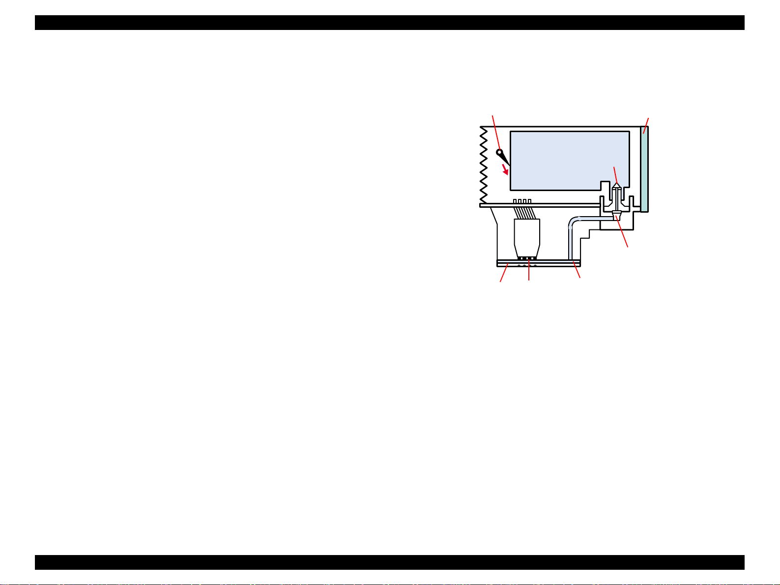
2.1.1.9 Capping Mechanism
The capping mechanism, which is driven by the pump unit, caps the printhead
closely to maintain air tightness of the cap. This operation is required to
vacuum ink from the ink cartridges, printhead, cavity, and cap. Also, to moisten
the inside of the cap while the printer power is off, this mechanism works to
keep the cap and the printhead surface in a tight contact. This function
prevents ink from clogging while the printer is not in use.
SC440/640/740 models
Flag for Carriage
Negative pressure
Ink Eject Valv e
Valve
For a specific feature of the Stylus COLOR 860/1160, it has a newly designed
valveless capping mechanism instead of other printers’ capping mechanism
that integrates an air valve. An air valve is usually equipped to remove bubbles
created inside the cap by releasing the negative pressure. However, due to
change in the ink sequence, the new valveless capping mechanism enables
this printer to maintain the initial ink charge and cleaning effects at the same
level as before. Figure 2-13 outlines the valveless capping mechanism.
SC860/1160 models
Flag for Carriage
Ink Eject Valve
Negative pressure
Closed state
Released state
Flags for
Frame
Air valve is not assembled
in this portion.
Figure 2-13. Valveless Capping Mechanism
Operating Principles Overview 39
Page 40

EPSON Stylus COLOR 860/1160 Revision C
2.2 Electrical Circuit Operating Principles
The electric circuit of the Stylus COLOR 860/1160 is composed of the following
boards.
o
Main board: C298MAIN (Stylus COLOR 860/1160)
o
Power supply board: C298PSB/PSE (Stylus COLOR 860/1160)
o
Panel board: C298PNL (Stylus COLOR 860)
C304PNL (Stylus COLOR 1160)
Refer to Figure 2-13 for the major connection of the three boards and their
roles.
C 298 P N L B oard (S C 860)
C 304 P N L B oard (S C 1160)
C 298 M A IN B oard
3.3V R egulator
Power off
+5VD C
C298 PSB/PSE
Board
+42VD C
Printer M echanism
C R M otor
PF M otor
AS F/P um p M otor
H ead D river B oard
Several S ensors
Figure 2-14. Electric Circuit of Stylus COLOR 860/1100
Operating Principles Electrical Circuit Operating Principles 40
Page 41

EPSON Stylus COLOR 860/1160 Revision C
2.2.1 C298PSB/PSE Board
The Stylus COLOR 860 and Stylus COLOR 1160 are equipped with the
C298PSB/PSE, the common power supply board for the both products. The
basic structure of the circuit is the same as for the C257PSB/PSE board used
in the Stylus COLOR 740. The power supply boards of these printers use a
RCC switching regulator, which generates +42VDC for drive line and +5VDC
for logic line to drive the printer. For one of the major characteristics of the
C298PSB/PSE, it uses the secondary switch that is also used in the Stylus
Color series. Use of the secondary switch enable the circuit to keep supplying
voltage to 5 V line and 24 V line for approximately 30 seconds if the printer
power is turned off through the panel switch. This extra time allows the printer
to perform the following operations when the printer is turned off through the
panel switch while it is in operation.
o When the printer is in a printing state, if the CR unit is away from the home
position, the CR unit can return to the home position to be locked before
the printer power shuts down.
o When the printer is not in a printing state, if paper fed from ASF remains in
the printer, the paper is ejected before the printer power shuts down.
Table 2-9 in the right column shows the application of each voltage generated
by C298PSB/PSE board.
NOTE: The 5VDC is only applied to the parts and locations shown in the Table 2-9.
The C298MAIN, like the C267MAIN-B board*, uses the 3.3V drive chips for
most of the logic line chips (CPU, ASIC, ROM, DRAM). For this reason, those
chips are not driven by the +5VDC but 3.3VDC that is reduced by the IC9
(3.3VDC regulator) on the C298Main Board.
* Used in the minor changed models of the Stylus COLOR 740, Stylus Pro
750, and Stylus Pro 1200.
Figure 2-15 in the right column shows the block diagram for the C298PSB/PSE
board. The process from the input of AC voltage to the output of 42 V DC and 5
V is explained in the following page.
Table 2-9. Application of the DC Voltages
Voltage Application
+42VDC
CR Motor, ASF/Pump Motor, PF Motor
Head driving power supply
Sensor circuit power supply voltage
LED panel drive power supply
+5VDC
Nozzle selector control signal voltage
I/F Control Circuit
Slave CPU for DC motor control
ZD90
+42VD C Lin D rop
L im ita tio n C irc u it
C84,Q84
Power Drop
Delay Circuit
PSC S ignal
from M ain board
PC1
+42 V D C
D51
+5 VD C
IC 5 1
+5V R egulator
ZD 81-86,Z D 51
+42VD C Line
C onstant C ontrol
C51
Sm oothing
Circuit
ZD53
+5V D C Line
O ver Voltage
L im ita tio n
ZD 52,87
+42VD C Line
O ver Voltage
L im ita tio n
TRANS(T1)
AC Input
C11
Sm oothing
Circuit
O ver C urrent
Protection
F1, TH 1
Q1
M ain S w itching
Circuit
F ilte r C irc iu t
L1, C 1,C 2
Q2,Q3,Q31
Full W ave
R e c tifie r c ir c u it
DB1
Abnorm al
Feed back circuit
Photo
Coupler
Figure 2-15. C298PSB/PSE Board Block Diagram
Operating Principles Electrical Circuit Operating Principles 41
Page 42

EPSON Stylus COLOR 860/1160 Revision C
1. Regardless of the state of the power switch (On or OFF), the voltage is
always applied to the primary side of the power supply board from the
moment or at the state that AC-plug is plugged in. At this time, F1 plays a
role of preventing AC100V from coming into the F1.
L1 also prevents high harmonic wave noise generated in the RC circuit
filter which consists of C1,C2 from going out, and eliminates the noise from
outside here.
2) The AC is full-wave rectified by the diode bridge DB1, and converted to
x AC in voltage by the smoothing electrolytic capacitor C11.
2
3) The pressured up direct current turns Q1 on through the starting resistor
R31 and starts the primary side of the circuit.
4) When the primary side is On, the energy (current) led by the
electromagnetic induction through the trans (T1) does not flow to the
secondary side since the diode (D51) on the secondary side is installed in
the opposite direction.
5) When the energy which is charged in the trans is reaching the saturated
state, the voltage which makes Q1 on becomes weak gradually. At the
point that this voltage drops at the certain voltage, C13 absorbs the current
in the opposite direction and Q1 is quickly shut off by the resulting sharp
drop.
6) When the primary side is turned off, the energy charged in the T1 is
opened according to the diode(D51 ) dire ction whi ch is inst all ed on the
secondary side. Basically, 42 V DC is output by these circuit operations
and the number of T1 spiral coil.
7) +5VDC is generated by pressured down this +42VDC as power supply.
IC51 pressures down the +42VDC and generates precise +5VDC by
chopping off the output, forming the standard santooth wave form by the
outer RC integration circuit.
The C298PSB/PSE board has the various control circuits to stop voltage
output if a malfunction occurs on the power supply board or the main board or
while the printer mechanism is on duty. Following explains each control and
protection circuit.
o +5V line over voltage protection circuit:
This protection circuit is in the same line as the +42V over voltage
protection circuit is located. The output voltage level of the +5V line is
monitored by a Zener diode. This circuit shuts down the +5V line forcefully
when the voltage level exceeds +9V.
o +42VDC line drop limitation circuit:
This protection circuit is in the same line as +42V over voltage protection
circuit is located. The output voltage level of the +42V line is monitored by
a Zener diode. This circuit shuts down the +42V line forcefully when the
voltage level drops to +36V.
o +42VDC line over voltage circuit:
This circuit is in the same line as +5V line over voltage protection circuit is
located. The output level is monitored by two Zener diodes. If the voltage
level exceeds +48VDC, this circuit shuts down the +42V line forcefully.
o +5V line constant voltage/constant current control circuit:
The output current is monitored by the +5VDC generation switching control
IC (IC51), which also monitors the output voltage. This information is input
to the internal comparator and stabilizes +5V line. The operations of the
secondary side switch are explained below.
n When the power is turned on, Q1 repeats on/off automatically along
with the increase and decrease of energy on the trans coil at the
primary side. While the power is on, the PSC signal is input to the
power supply board from the C298MAIN board.
n This signal turns Q84 on and it becomes possible to discharge energy
between the terminals 8 and 9 of T1. At this time, even if the power is
turned off, the electrolytic capacitor keeps Q84 on for a while, and by
this electrolytic capacitor, voltage output is held at least 30 seconds.
This time helps the printer to complete a power-off operation.
o +42V Line Constant Voltage Control Circuit:
The output level of the +42V line is monitored by a detection circuit
composed of the seven Zener diodes. This circuit prevents the voltage
from dropping for a constant level of the output voltage .
Operating Principles Electrical Circuit Operating Principles 42
Page 43

EPSON Stylus COLOR 860/1160 Revision C
2.2.2 C298MAIN Board
The logic circuit of the C298MAIN is composed of the following:
n Logic line (CPU, ASIC, DRAM, EEPROM, and so on)
n Various motor control/driver circuits (CR motor, PF motor, and ASF/
Pump motor)
n Head control/driver circuits
n Interface control (parallel I/F, USB I/F)
n Sensor circuits
n Timer circuits
n Reset circuits
This main board is mainly different form other models in the following two
points.
o Us e of the 3.3V chip s in the log ic circu it
The 3.3 V regulator (IC9) on the C298MAIN produces 3.3 V by pressuring
down the 5.5 VDC, also generated on this board, to drive several chips.
See the table below that separately shows the chips driven by the +5V and
+3V.
Table 2-10. 3.3V Drive Chips & 5.5V Drive Chips
+5V 3.3V
P-ROM 16M
(IC2)
C90A11CA
CPU (IC20)
CN3
USB
IC7
IC21
Address
Data
Address
Data
E0BA13KA
PDIUSBF11A
CR Encoder senser
Head
D-RAM 16M
(IC3)
E05B70OD
ASIC (IC8)
CN8 HD FFC
Batt1
CN12
CN9 HD FFC
CR1
Timer &
Reset IC
(IC5)
EEPROM
(IC6)
C90A120A
Slave CPU (IC15)
CN11
CN 6
CN5
PE Sensor
PF Encoder Sensor
Q3&Q4
Common
Driver
(IC10 or
IC11)
IC4
74VHC1612B4
CN14
Motor
Driver
(IC18)
C298 PNL (for SC860)
C303 PNL (for SC1100)
ASF Sensor
CR Motor
PF Motor
CN13
Motor
Driver
(IC19)
CN1 Parallel
ASF/Pump Motor
CN7
Motor
Driver
(IC12)
Sensors
I/F Circuit
PNL Board
Slave CPU
o
Use of the slave CPU
CPU
ASIC
P-ROM
D-RAM
Figure 2-16. Block Diagram for the C298MAIN Board
Since the CR motor and PF motor of this printer are DC motors, the slave
CPU is attached on the main board in addition to the CPU and ASIC. This
slave CPU, serving to control the DC motors only, reduces duty of the CPU
and ASIC for faster data processing.
See Figure 2-16 for the C298MAIN board block diagram.
Operating Principles Electrical Circuit Operating Principles 43
Page 44

EPSON Stylus COLOR 860/1160 Revision C
Table 2-11 shows the functions of the CPU, ASIC, and slave CPU.
Table 2-11. Functions of the CPUs and ASIC
IC Location Function
• Sets the c urrent value for the ASF/Pump motor.
CPU IC20
ASIC IC8
Slave CPU
for DC
motors
IC15
• Measures the printhead tem per ature .
• Several interrupting functions
• Outputs the system clock sig nal.
• Controls interfaces.
• Controls the printhead drive waveform circ uit.
• Transfers serial data to the printhead.
• Controls the ASF/Pump motor
• Receives panel control signals and sensor signals
• EEPROM
• Controls detection of the signals output from the
encoder.
• Sets the current value for the PF motor and CR
motor.
• Controls the PF motor and CR motors.
Operating Principles Electrical Circuit Operating Principles 44
Page 45

EPSON Stylus COLOR 860/1160 Revision C
2.2.2.1 Printhead Driver Circuit
The printhead driver circuit consists of the following two components:
n Common driver IC (IC10: E09A14RA) directly attached to the
C298MAIN board.
n Nozzle selector IC (Sharp IR2C95F or EPSON SED6125T0A) on the
head board.
F1
The common driver (IC10: E09A14RA) generates a reference drive waveform
according to the output signals from the C298MAIN board. The reference drive
waveform is amplified by the transistors Q3 and Q4 and then transferred to the
nozzle selector IC on the head board. Print data is converted to serial data by
the ASIC (IC8 E05B70CD) and then sent to the nozzle selector IC on the head
board. Based on the serial data, the nozzle selector IC determines the nozzles
to be actuated. The selected nozzles are driven by the drive waveforms
produced by the common driver. See Figure 2-17 for the printhead driver circuit
block diagram.
o Head common driver circuit
The reference head drive waveform is produced in the common driver
(IC10: E09A14RA) based on the following 12 signal lines output from the
ASIC (IC8 E05B70CD); A0-A4, CLK1, CLK2, RST, FLOOR, DATA, DCLK,
and E.
By the DATA signal output from the ASIC (IC8 E05B70CD), the original
data for the head drive waveform is written in the memory in the IC10. The
addresses for the written data are determined by the A0 - A4 signals, and,
of among, data used to determine the waveform angles is selected. Then,
setting the selected data, producing trapezoid waveform value, and
canceling the data are performed by the rising edges of the CLK1 and
CLK2 signals.
o Head nozzle selector circuit
Printing data is converted into serial data by the ASIC (IC8 E05B70CD).
Then the converted data is allocated to the six rows, the number of the
head nozzle rows, to be transferred to the nozzle selector (Sharp
IR2C95F) through the six signal lines (HS01 to HS06). Data transmission
from the ASIC (IC8 E05B70CD) to the nozzle selector synchronizes with
the LAT signal and SCK clock signal. Referring to the transferred data,
nozzles to be activated are selected, and the PZTs of the selected nozzles
are driven by the drive waveform output from the head common driver.
HW A0
HW A1
HW A2
HW A3
HW A4
HW CLK1
HW CLK2
HW FLR
HW RST
HW SDATA
HW SCLK
HW SLAT
IC 8 A S IC
E05B70C D
HCH
HLAT
CRAI0
CRAI1
SW CO
SW C1
HS01
HS02
HS03
HS04
HS05
HS06
HSOCMD
HSOCLK
to C P U A N 0 p o rt
AO
A1
A2
A3
A4
CLK1
CLK2
FLOO R
RST
DATA
DCLK
E
IC 1 0
Commom
D r iv e r IC
VCC
NPNB
FB
PNPB
CN8
CN9
CN9
COM
COM
COM
COM
VHV
VHV
CH
LAT
ENA
ENB
N o z z le S e le c o r IC
IR 2C 95F
COB
COA
SI1
SI2
SI3
SI4
SI5
SI6
SP
NCHGHNCHG
SCK
THM
Figure 2-17. Printhead Driver Circuit
H ead D rive
P u ls e
Operating Principles Electrical Circuit Operating Principles 45
Page 46

EPSON Stylus COLOR 860/1160 Revision C
2.2.2.2 Reset Circuit
Reset circuits are attached on the C298MAIN board to monitor the two
voltages: +5V for the logic line and +42V for the drive line. When each circuit
detects abnormality on the corresponding line, it outputs a reset signal to reset
CPU and ASIC. This function is necessary to prevent the printer from operating
abnormally. IC5 RTC-9820SA, a reset circuit IC, is attached directly on the
main board. This IC monitors both the +5V and +45 lines but can reset them
independently. See Figure 2-18 for the block diagram for the reset circuits.
o +5V line reset circuit
The VDD port of the IC5 reset IC monitors the +5V line. When the IC
detects an abnormal voltage level (4.3 V or lower), it outputs a reset signal
from the RST port to CPU and ASIC.
o +42V line reset circuit
The VIN port of the IC5 reset IC monitors the +45V line. When the IC
detects an abnormal voltage level (35.5V or lower), it outputs a reset signal
from the VDT port to CPU and ASIC.
NOTE: IC5, also serving as RIC (Real Time Clock), manages timer control when the
printer power is turned off. Power for this operation is supplied from the BAT1.
+42V
+5V
VIN
VDD
D2
SB007-03C PTB
BAT1
CR2032
C18
0.1U
C19
0.1U
C21
0.1U
VBK
GND
Figure 2-18. Reset Circuit Block Diagram
VDT
FRST
RST
C E
SCLK
DATA
+3.3V
R26
3.3K
R27
3.3K
IC 8
E05B 70C D
NMI
MRES
RESET
TCE
TCLK
TDATA
Operating Principles Electrical Circuit Operating Principles 46
Page 47

EPSON Stylus COLOR 860/1160 Revision C
2.2.2.3 CR Motor Driver Circuit
The Stylus COLOR 860/1160 is equipped with a DC motor for the CR motor. In
addition to the CPU and ASIC, a slave CPU is mounted on the C298MAIN
board. Since the slave CPU is exclusively used to control DC motors, it
reduces duty of CPU and ASIC to offer faster data processing.
o CR motor driver circ uit
The internal equivalent circuit of the CR motor driver IC (LB1947) is as
shown below.
CN8
Head FFC
ENA
ENB
IC 8
E05B70C D
CRAI0
CRAI1
NMI
RXD1
TXD 1
CRBI3
CRPH AB
CREN BB
CRAI2
CRBI2
CRBI3
CPU
P25
IC 1 5
C 90A 13C A
NMI
P31
P33
P32
P30
P64
RES
MD2
P12
P11
P13
P27
P26
PE1
PE2
PE0
PE4
PA0
DA1
+42V
IC 1 8
LB1947
VBB
IN 1
IN 2
ST
VI
MD
VREF
R138
4.4B K
-
R139
4.99B K
OUTA
OUTB
CR
E
GND
IC 2 4
M 62552FP
+5V
R112
0.499
-
+
C 117
1500p
C115
0.1U
CR-A
CR-B
R 115
68BK
R114
12.7K
Unlike a stepping motor, the DC motor that drives the carriage
can not detect
the current carriage position by referring to the pulses given. For this
reason, a linear scale is attached along the carriage operation range to
detect the carriage position. The linear encoder sensor outputs two
kinds of TTL level pulses Phase A and Phase B to IC8 ASIC.
1/180 inches
1/720 inches
Phase A
Phase B
Phase A
Phase B
LED
LEN S
Photo
D iodes
1/360 inches
CR Motor CW rotation
CR motor CCW
C om parators
A
+
A
-
B
+
B
-
Phase A
Phase B
Figure 2-19. Internal Equivalent Circuit of the CR Motor Driver IC
The
IC15 slave C PU
from the linear encoder via IC8 ASIC. The CPU also sets an appropriate
drive current value for the CR position and the direction in which the CR
moves based on the data transmitted from the ASIC. So the slave CPU
outputs specified control signals to the motor driver. The motor driver IC18
then outputs the CR motor drive current to the CR motor based on the
signals sent from the
controls the CR position by referring to the pulses sent
IC15 slave CPU
.
Direction for the current CR’s movement is detected based on the waveforms
of the Phase A and Phase B that are out of phase, while carriage position is
controlled by using the waveforms output from Phase A on a cycle basis (1
cycle: 1/180 inches). Phase between the output waveforms A and B is as
shown in Figure 2-20. Note all edges in Phase A, Phase B output waveforms
(1/720-inch cycle) are used to control the CR position while it is in the home
position for ink system.
Figure 2-20. CR Linear Scale Encoder Pulse
Operating Principles Electrical Circuit Operating Principles 47
Page 48

EPSON Stylus COLOR 860/1160 Revision C
o
Home position detection (capping position detection)
Home position is detected based on the pulses output from the linear scale
sensor and CD motor control current value. The basic home position
detection sequence is as described below:
1/180 inches
1)The linear encoder pulse counter in the IC15 slave CPU is reset during a
power-on sequence.
2)The CR motor moves clockwise and the CR moves from left to right.
IC15 slave CPU once assumes that the CR comes in contact with the
right frame when the following conditions are satisfied:
nThe slave CPU detects the motor control current value 720mA
nP1 (= number of pulses output for the above CR movement) is 30* or
less.
* Specified value that indicates CR is movable in the home position.
(All edges in the waveform are used in this condition.)
3)The CR motor rotates counterclockwise and the CR moves from right to
left, and the IC15 slave CPU assumes that it detects the CR lock lever
position when the following conditions are satisfie d:
nIC15 slave CPU detects the motor control current value 500 mA.
nDifference X between P1 and P2 (= number of pulses output while
the CR moves from the right frame) is 30 or less.
4)The CR motor rotates counterclockwise and the CR moves from left to
right again, and if IC15 slave CPU detects the motor control current
value 720 mA, it assumes that the CR comes in contact with the right
frame again.
5)Difference between P1 and P3 (= number of pulses output for the CR’s
movement from the CR lock lever to the right frame) is 4 or less.
Phase A
PTS
1/360 inches
Figure 2-21. Print Timing Signal and Linear Encoder Phase A
NOTE: If the drive voltage for the CR motor reaches 800mA, a fatal error occurs.
When all conditions in the sequence are satisfied, the printer detects the CR is
in the home position.
o PTS (Print Timing Signal) production
The circuit produces PTS signal (cycle: 1/360 inches) by dividing waveform
cycles for Phase A (cycle: 1/180 inches). The print timing signal is used to
eject ink at a correct timing.
Operating Principles Electrical Circuit Operating Principles 48
Page 49

EPSON Stylus COLOR 860/1160 Revision C
7
2.2.2.4 PF Motor Driver Circuit
TheStylus COLOR 860/1160 is equipped with a DC motor for the PF motor. In
addition to the CPU and ASIC, a slave CPU is mounted on the C298MAIN
board. Since the slave CPU is exclusively used to control DC motors, it
reduces duty of CPU and ASIC to offer faster data processing. The block
diagram for the PF motor driver circuit is as shown below:
OUTA
OUTB
CP1
CP2
VREG
SENSE
GND
GND
GND
IC 2 4
M 62552FP
+42V
C119
0.22U
C120
022U
-
+
C 116
0.22U
R113
0.24
PF-A
PF-B
C13
0.1U
CN12
PF Encorder
ENA
ENB
IC 8
E05B70CD
CRPHAA
CRENBA
NMI
RXD1
CRBI3
CRPHAB
CRAI2
CRBI0
CRAI3
CPU
P25
IC 1 5
C 90A 13C A
NMI
P31
P33TXD 1
P32
P30
P64CRENBB
RES
MD2
P17
P15
P20
P21
PD3
PD1
PD0
PD4
PD6
PD5
PD7
DA0
SCO N
IC 1 9
A3958S B
MODE
PHASE
ENABLE
RANGE
REF
OSC
CLO CK
DATA
STOROBE
R138
4.4B K
R139
4.99B K
Unlike a stepping motor, the DC motor that drives the PF motor can not detect
a paper feeding amount by referring to the pulses given. For this reason, a loop
scale is attached on the Gear 76 to mechanically detect a paper feeding
amount.
The loop scale encoder sensor outputs two kinds of TTL level pulses Phase A
and Phase B to IC8 ASIC.
1/1440 inches
Phase A
Phase B
PF motor CW rotation
1/5760 inches
Phase A
PF motor CCW rotation
Phase B
LEN S
Photo
D iodes
C om parators
A
LED
+
A
-
Phase A
B
+
B
-
Phase B
Figure 2-22. PF Motor Driver Circuit Block Diagram
IC15 slave CPU controls paper feeding amount by referring to the encoder
pulses sent from IC8 ASIC. It also sets a proper drive current value according
to the paper feeding amount and direction. So it outputs specified control signal
to the motor driver. The motor driver IC19 outputs PF motor drive current to the
PF motor according to the control signals from the IC15 slave CPU.
Rotational direction of the PF motor is determined by the phase between the
output waveforms of Phase A and Phase B. Refer to Figure 2-23 for different
phase for each direction.
NOTE: If the drive voltage for the PF motor reaches 1A, a fatal error occurs.
Figure 2-23. Loop Scale Encoder Pulse
Operating Principles Electrical Circuit Operating Principles 49
Page 50
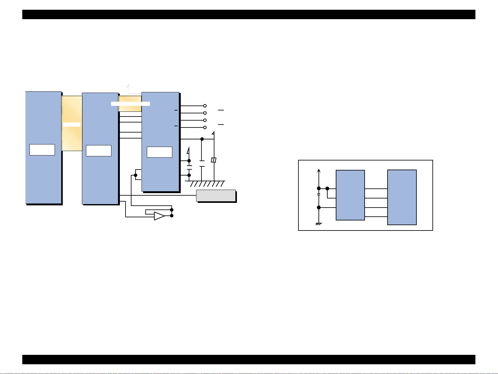
EPSON Stylus COLOR 860/1160 Revision C
2.2.2.5 ASF/Pump Motor Driver Circuit
The block diagram for the ASF/Pump motor is as shown below:
+42V
IC 8
E05B70CD
DATA Bus
PFPHAA
PFPHAB
PFENBA
PFENBB
IC 1 5
C90A13CA
SW A2
Current control signals
PHASE1
PHASE2
ENABLE1
ENABLE2
VREF1
VREF2
DA0
IC 1 2
LB11847
+
OUTA
OUTA
OUTB
OUTB
VBB
VCC
GND
IC 2 2
SN 104B 00P S R
C69
0.1U
ASF-A
ASF-A
ASF-B
ASF-B
+42
C79
C75
100U
0.1U
CN6
ASF SEN SO R
2.2.2.6 EEPROM Control Circuit
Since EEPROM is nonvolatile memory, it keeps information written if the
printer power is turned off. Information stored in EEPROM is various
adjustment values, factory values, and printer status values. See Appendix for
EEPROM Address Map that provides detailed information on the values stored
in EEPROM.
EEPROM is connected to ASIC with 4 lines and each line has the following
function.
n CS: Chip selection signal
n CK: Data synchronism clock pulse
n DI: Data writing line (serial data) at power off.
n DO: Data reading line (serial data) at power on.
The EEPROM control circuit is as shown below:
+5V
8
6
5
93C 56
(IC 7 )
Vcc
ORG
GND
CS
SK
DO
DI
1
2
3
4
206
205
204
203
E05B 70C D
(IC 8 )
EECS
EECK
EECO
EECI
Figure 2-24. ASF/Pump Motor Circuit Block Diagram
Figure 2-25. EEPROM Circuit Block Diagram
Operating Principles Electrical Circuit Operating Principles 50
Page 51

EPSON Stylus COLOR 860/1160 Revision C
r
2.2.2.7 Sensor Circuit
The Stylus COLOR 860/1160 is equipped with the following five sensors to
detect the status of the printer.
n I/C detection sensor
n Head Thermistor sensor
n PE sensor
n ASF home position sensor
n PF motor encoder sensor
n CR unit encoder sensor
The block diagram for the sensor circuit is as shown below:
CN4
PE Sensor
PRV
C89
GND
C90
PE
CN6
ASF H P Sensor
ASFV
C93
GND
C94
ASF
CN12
PF M otor E ncoder S ensor
ENA
ENB
CN8
C R M otor E ncolder S ensor
ENA
ENB
CN9
I/C D e te c tio n S e n s o r & T h e r m is to
COB
CCB
THM
IC 2 0 C P U
C90A11CA
+5v
R57
200
SW A1
AN0
DATA Bus
+5v
IC 8 A S IC
E05B 70C D
SW A2
CRPHAA
CRENBA
CRAI0
CRAI1
SW C0
SW C1
R93
200
Figure 2-26. Sensor Circuit Block Diagram
Function and detection method of each sensor is as described below.
o I/C detection sensor (for black I/C and color I/C)
The I/C detection sensor included in the CR unit determines whether a
black or color ink cartridge is installed. When an I/C is installed, this sensor
detects a mechanical contact with the cartridge and outputs a LOW signal
to the ASIC. If no cartridge is installed, it outputs a HIGH signal to the
ASIC.
o Head thermistor
The head thermistor is attached directly on the head driver board. It
monitors the temperature around the printhead and feeds back the
temperature to the CPU analog port. The printer refers to this information
to control head driver voltage based on the ink viscosity.
o PE sensor
The PE sensor is located at the bottom right edge of the top frame in the
printer mechanism. This sensor detects paper on the rear paper guide,
using a photo sensor and PE sensor lever that are included in the sensor.
When paper passes, the PE sensor does not interrupt the photo sensor
terminals. So a LOW signal is output to the ASIC. If there is no paper, on
the other hand, the lever cuts in between the photo sensor terminals, which
outputs a HIGH signal to the ASIC.
o ASF HP sensor
The ASF HP sensor, located at the left edge of the ASF, detects the ASF
home position. This sensor consists of the ASF HP detector wheel and a
photo sensor. A small portion of the ASF HP sensor has a cutout, and
when the cutout comes into position between the photo diode terminals,
ASF home position is detected. In this status, the photo diode terminals are
not blocked, and a LOW signal is output to the ASIC. Referring to the ASF
home position detected by this sensor, the printer drives the ASF/Pump
motor to set the LD roller and paper return lever ready for paper loading.
o PF moto r enc ode r sens or
The PF motor encoder sensor includes the loop scale attached to the left
end of the PF roller and the linear encoder. The minimum resolution of the
sensor is 1/1440 inches (minimum 1/5760 inches with all edges of Phase A
and Phase B), and the sensor outputs HIGH signals for the black lines and
LOW signals for the transparent parts to the ASIC. The printer controls the
PF motor based on the signals output from this sensor.
Operating Principles Electrical Circuit Operating Principles 51
Page 52

EPSON Stylus COLOR 860/1160 Revision C
o
CR unit encoder sensor
CR unit encoder sensor includes the linear encoder in the CR unit and the
scale plate attached along the CR scanning direction. The minimum
resolution of the sensor is 1/180 inch, (minimum 1/720 inches with all
edges of Phase A and Phase B) and outputs HIGH signals for the black
bands of the scale and LOW signals for the transparent parts to the ASIC.
The printer controls the CR motor based on the signals output from this
sensor. The sensor also detects the CR home position.
Operating Principles Electrical Circuit Operating Principles 52
Page 53

TROUBLESHOOTING
CHAPTER
Page 54

EPSON Stylus COLOR 860/1160 Revision C
3.1 Overview
This chapter describes how to troubleshoot problems. It consists of the
sections shown in the flowchart below. When identifying and
troubleshooting problems, be sure to proceed to the correct section
specified in the flowchart.
No
Isolating the faulty part
on the pow er supply
board
(Section 3.1.2)
Is the printer pow er on?
Yes
Troubleshooting w ith
LED error indications
(Section 3.1.1)
Isolating the faulty part
according to the
exhibited phenom enons
(Section 3.1.3)
Following sections show detailed informat ion on each step in the
flowchart. Be sure to perform troubleshooting without neglecting the
correct order specified in each section.
First of all, following tables show you the Motor Resistance and the
sensor check informations.
Table 3-1. Motor Resistance and Measurement Procedure
Motor Name Location Check Point
CR Motor • CN14 (Main boa rd) Pin 1 & 2, 31.1 OHM +/- 25%
PF Motor • CN13 (Main Board) Pin 1 & 2, 31.1 OHM +/- 25%
ASF/Pump Motor • CN7 (Main Board) Pin 1& 3,
Pin 2 & 4,
10.4 OHM+/-10%
Table 3-2. Sensor Check an Measurement Procedure
Sensor Connector No.
PE Sensor CN4 Pin 1 & 2 •0V
ASF/HP Sensor CN6 Pin 1 & 2 • 0V
PF Motor
Enscorder Sensor
CR Motor
Encorder Sensor
Black I/C
Detection Sensor
Color I/C
Detection Sensor
CN12 •0V
CN8 • 0V
CN9
Pin 15 & Pin 18
CN9
Pin 15 & Pin 17
Measurement
value
•5V
• 5V
•5v
•5v
•5V
•0V
•5V
•0V
Status
Detect the Paper
No Paper
Detect the ASF HP
Not detect ASF HP
Transparency slit
Black Slit
Transparency slit
Black Slit
I/C is not installed
I/C is installed
I/C is not installed
I/C is installed
Figure 3-1. Troubleshooting Flowchart
Troubleshooting Overview 54
Page 55

EPSON Stylus COLOR 860/1160 Revision C
3.1.1 Troubleshooting with LED Error Indications
This section describes how to troubleshoot the problem when the
printer indicates an error at power on and can not print . The Stylus
COLOR 860/1160 can detect the following six errors and seven status,
and indicates them with the LEDs, as shown below.
Table 3-3. Error Indication of Operation Panel
Printer Status
Power On Condition On - - - 9
Ink Sequence Blink - - - 6
Ink Cartridge Replacement
Mode
Data Processing Blink - - - 8
Paper Out On Off Off On 4
Paper Jam Condition On Off Off Blink 3
No Ink Cartridge / Ink End
(Black)
Ink Level Low (Black) - Blink - - 7
No Ink Cartridge or Ink End
(Color)
Ink Level Low (Color) - - Blink - 7
Enter EEPROM and Timer IC
Reset
Maintenance Request Blink Blink Blink Blink 2
Power Ink Out (Black) Ink Out (Color) Paper Out
Blink - - - 5
-On- -7
--On-7
- ON (for 1 second only) -
Indicators
Priority
Fatal Error Blink On On Blink
1
Troubleshooting Overview 55
Page 56

EPSON Stylus COLOR 860/1160 Revision C
See the following tables which show the error conditions and
corresponding possible causes:
Table 3-4. Error Condition and the Possible Causes
No. Error Condition Possible Causes
1 Paper Out Error
(Refer to Section
3.1.1.1.)
2 Paper Jam Error
(Refer to Section
3.1.1.2.)
3 NO I/C or Ink Out
Error (Refer to
Section3.1.1.3)
4 Maintenance
Error (Refer to
Section 3.1.1.4))
1. Failure in paper feeding
2. Connector for the PE sensor is disconnected.
3. The PE sensor actuator is acting improperly.
The sensor base is not fixed properly.
4. The PE sensor is defective.
5. ASF dose not move co rrectly
1. The paper in use is longer than specified.
2. The PE sensor remains on because it is covered with
paper debris or dust.
3. The PE sensor actuator is not acting properly.
The sensor base is not fixed properly.
4. The PE sensor is defective
5. The Hopper Release Lever is not assembled correctly.
1. The counter is not showing the actual remaining ink
level.
2. Ink cartridge sensor actuator is not acting properly.
3. The micro switch is not mounted correctl y.
The connector (green) is disconnected.
4. The connector (green, 3-pin) on the small board
directly attached to the printhead surface side is
disconnected. Note the connector (green, 4-pin) is
irrelevant as it is for the encoder.
5. The micro swi tch is defecti ve.
6. The value for the ink consumption counter in the
EEPROM is destroyed.
Usual waste ink over-flow is requested.
Note this error can be cleared by the special function
through the control panel operation and the Adjustment
program.
Table 3-4. Error Condition and the Possible Causes (continued)
No. Error Condition Possible Causes
5 Fatal Error
(Refer to Section
3.1.1.5)
1. The CR Encorder FFC has come off from the CR
Encorder Sensor board.
The CR Encorder sensor is not mounted in the CR
Assy.
2. The CR liner scale has come off.
The CR liner scale is not placed through the encoder
located at the back of the carriage.
3. The ASF sensor has come off.
The connector for the ASF sensor is not disconnected.
4. The ASF sensor is defective or dose not detect the
ASF HP position caused by any factor.
5. The PF or CR Encorder Sensor is defective or dose
not detect the slite pattern on the each scale.
6. The coil for the CR motor has burnt.
7. The coil for the PF motor has burnt.
8. Coil for the ASF/Pump motor has burnt
9. ASF Gear 32 is disengaged to the Combination Gear
14,28 which is assembled in the DE unit.
10. Torsion Spring 0.618 comes off from the DE Lock
Lever and the hook of DE unit.
Troubleshooting Overview 56
Page 57

EPSON Stylus COLOR 860/1160 Revision C
3.1.1.1 Remedies for Paper Out Error
This section provides check points and corres ponding actions which are
necessary when the Paper Out Error problem has occurred because of
either of the following reasons:
n Paper is set in the ASF hopper but not fed.
n Paper is fed but not detected by the PE sensor actuator.
Be sure to follow the steps in the order described in the tables.
NOTE:If the finding the detail phenomenon which fits the defective
printer, take the Check & Action described in the right col umn.
If “No”, proceed to the next step.Remedies for Paper Error.
Table 3-5. Remedies for Paper Out Error
Step Detail Phenomenon Check & Actions
1 When the Paper
Feed SW is pressed,
the ASF LD roller
attempts to feed the
paper. But the paper
is not loaded.
After that, the Panel
LED indicates the
Paper Out Error.
2 When the Paper
Feed SW is pressed,
the ASF LD roller
feeds the paper to
the PF roller.
But, ASF LD roller
rotates again an d the
PF roller advances
the paper over the
TOF position.
After that, the Panel
LED indicates the
Paper Out Error.
3 Ditto
Set a cleaning sheet in the ASF up side down. Then
holding the top edge, press the Load/Eject button, and
the micro pearl on the paper load roller (a semicircular
roller) surface is removed. To remove severe smear,
staple a cloth moistened with alcohol to a post card and
clean the roller in the same manner.
N on-adhesive A rea
C L S heet
Adhesive A rea
This side dow n
Check if the connector (yellow, 3-pin) fo r the PE sensor
is connected to PE sensor or CN5 on the Main Board.
Bottom view of the printer m echanism
C onnector for the
PE sensor
• Using your hand, try activating the actuator in the
same condition as it is det ecting incom ing pa per. Then
release the actuator and check if the actuator
automatically returns to its original position with the
tension of the spring.
• Referring to the illustration above , chec k that the
sensor base is securely installed to the frame. If the
sensor base is floating or installed insecurely, instal it
securely.
(U s e a p o s t c a r d
for the base sheet.)
Staplers
C loth m oistened
w ith alcohol
Tension spring
Troubleshooting Overview 57
Page 58

EPSON Stylus COLOR 860/1160 Revision C
Table 3-5. Remedies for Paper Out Error (continued)
Step Detail Phenomenon Check & Actions
4 When the Paper
Feed SW is pressed,
the Paper is ASF LD
roller feed the paper
to the PF roller.
But, ASF LD roller
rotate again and the
PF roller advances
the paper over the
TOF position.
After that, the Panel
LED indicates the
Paper Out Error.
5 When the Paper is
feed with the Load/
Eject SW, it seems
that the Hopper is
moving correctly. But,
the paper is not
loaded and the Paper
Out Error is indicated
on the Operation
Panel.
Check if the PE sensor is defective.
Measure the voltage at the yellow 3-pin connector CN5
on the Main Board by activating the actuator manually to
check that the voltage is correct as follows.
The actuator is in ter m inals: 5V
The actuator is out of terminals: 0V
Main Board
CN5
Pin 3 (PE)
Pin 2 (G N D)
M/C
RED
WHT
M/C
CRH PE ASF
BLK
M/C
Hand-rotate the shaft in the ASF in the paper feed
direction and check if the hopper hops out every time you
rotate the shaft.
NOTE: Even though the ASF HP sensor is in the prop er
condition for detecting th e ASF h ome posit ion, If
the hopper is not operating at the correct timing
for paper feeding, paper is not loaded.
Therefore, if the ASF sensor is working without
this correct combination, reassembly or replace
the ASF.
In case the ASF HP sensor detect the ASF HP
in the paper feed sequence, the Panel LED
indicates the Fatal Error.
Troubleshooting Overview 58
Page 59

EPSON Stylus COLOR 860/1160 Revision C
r
A
3.1.1.2 Remedies for the Paper Jam Error
This section includes the check points a nd correspondi ng actions whi ch
are necessary when the Paper Jam Error constantly occurs when the
printer is turned on or feeding paper.
The printer detects the Paper Jam Error in the following Condi tions.
n When the printer is turned on, the PE sensor detects the paper
and attempt to eject it by rotating the PF roller. But, the Low
signal (paper detect status) is not removed.
Be sure to follow the steps in the order described in the tables.
NOTE:If the finding for the question is Yes, take the action described in
the right column. If “No”, proceed to the next step.
Table 3-6. Remedies for Paper Jam Error
Step Detail Phenomenon Check & Actions
1 When the Paper is
ejected, the PF roller
advance the paper.
But, the Paper is not
ejected completely.
And, Paper Jam is
indicated.
2 When the printer is
turned on, the PF roller
rotates continuously
about 10 sec. After that,
Panel LED indicate s the
Paper Jam.
•Ditto
3
•Ditto
4
• When the Paper is
5
loaded from the ASF,
the Top of the Paper
is loaded to the PF
roller. But it dose not
reach to the Paper
Guide Front. And
Panel LED indicates
the Paper Jam.
If Paper Feed Operation
is repeated, Fatal Error
is indicate.
Make sure if the paper length is beyond the
specifications is used.
Make sure that any paper dust or material push
up the tip of the PE sensor Actuator.
Viewing the PE sensor from the front, check that
the actuator is the correct position: the actuator
falls in the cutout without any paper.
PE Senso
Actuator
PE P aper G uide
ssem bly (R ig ht)
PF R oller
Referring to Step 3 in Section 3.1.1.1 “Remedies
for Paper Out Error”, check the sensor condition.
Referring to Step 4 in Section 3.1.1.1 “Remedies
for Paper Out Error”, Check the sensor function.
Make sure if the ASF Hopper Release Lever is
assembled properly to the LD roller shaft in the
ASF.unit. Refer the following figure.
Left ASF Hopper
Right ASF Hopper
Troubleshooting Overview 59
Page 60

EPSON Stylus COLOR 860/1160 Revision C
3.1.1.3 Remedies for No I/C and Ink Out Errors
This section includes the check points a nd correspondi ng actions whi ch
are necessary when the black i nk (or color ink) LED comes on or blinks
at power on despite the ink cart ridge has been r eplaced wi th a new one .
Be sure to follow the steps in the order described in the tables.
NOTE:If the finding for the question is Yes, take the action described in
the right column. If “No”, proceed to the next step.
Table 3-7. Remedies for No I/C and Ink Out Errors
Step Detail Phenomenon Check & Actions
1 Dot missing occurs
despite the Ink end
condition is not
indicated. And the dot
missing number is
increased every
printing.
or
Enough ink is
remaining in the
cartridge, but the
printer shows the Ink
low or Ink end
condition and can not
continue to print.
2 If the I/C is removed
and reset into the CR
unit, the Ink Out LED
is not turn on and off.
Make sure the I/C was replaced with the new one in
the I/C replacement sequence. If not, explain the
situation to the user well and replaced the I/C with
new one in the I/C replacement sequence.
The ink consumption counter, sepa rately set for
black and color ink, adds up points according to ink
weight used to form one dot. This counter is reset
(the value returns to zero) when t he I/C replacemen t
sequence is performed and I/C is replaced. If the
I/C is replaced with the used I/C in the I/C
replacement sequence , the foll owin g adversit ies wi ll
occur.
• Ink has run out but the printer continues to print
and starts false firing, which damages the print
head.
If the new I/C is installed without entering the I/C
replacement sequence , the ink consumptio n counter
is not reset and the following adversities will occur.
• Enough ink is remaining in the cartridge, but the
printer shows the Ink low or Ink end condi tion and
can not continue to pri nt.
Turn the both actuators (rig ht and lef t) manua lly and
check that they properly push the micro switches.
Then, also check that the actuators return to their
normal conditions shown in the figure below
automatically.
M icro S w itches
Actuator 1
Actuator 2
Troubleshooting Overview 60
Page 61

EPSON Stylus COLOR 860/1160 Revision C
C
Table 3-7. Remedies for No I/C and Ink Out Errors (continued)
Step Detail Phenomenon Check & Actions
3 If the I/C is removed
and reset into the CR
unit, the Ink Out LED
is not turn on and off.
4 Ditto Remove the I/C Detector holder from the CR unit
5 Ditto
If the micro switch is not properly attached, the
actuators possibly fail to touch the micro switch.
Therefore, check that the micro switch is securely
attached to the carriage by the hooks.
onnector
M icro S w itches
H ooks
and check if the connector (green, 3-pin) is
disconnected from the head circuit board.
1. Keeping the left micro switch pressed down, place
the probes of the tes te r to the middle and left p ins
to check for electrical continuity.
2. Keeping the right micro switch pressed down,
place the probes of the tester to the middle and
right pins to check for electrical continuity.
Step1
Step2
Table 3-7. Remedies for No I/C and Ink Out Errors (continued)
Step Detail Phenomenon Check & Actions
6 Ditto If the address for the ink cons um pti on information in
the EEPROM is garbled and the printer shows the
Ink Out (Ink End) error constantly, the printer sets
the interface signal “BUSY” to High and stops
communication with any other peripheral devices.
Therefore, it is effective to replace the I/C with a new
one to forcibly overwrite the address with 00H.
Push 1
Push 2
See table 3.2 about the measuremen t valu e.
Troubleshooting Overview 61
Page 62

EPSON Stylus COLOR 860/1160 Revision C
3.1.1.4 Remedies for the Maintenance Error
While the printer is in this error condition, it disables all operations
including data communication except for the panel operat ion specified
to clear the error. Therefore, follow the steps described in Table 3-8 to
solve the problem.
Table 3-8. Remedies for the Maintenance Error
Step Actions Correct LED condition
1 Turn the printer on while pressing the
Load/Eject and the Cleaning buttons, and
the Paper Out LED starts blinking. (Blinks
for three seconds.)
2 While the Paper Out LED is blinking (for
three seconds), press the Cleaning button
for ten seconds.
The Paper Out LED is blinking.
The follo wing three red LEDs
blink and turn off.
Ink Out LED (Black), Ink Out
LED (Color), and Paper Out
LED.
NOTE:During the Step 2, if the Load/Eject button is pressed, the
Maintenance Error is not cleared but the EEPROM initialization
mode is activated instead. The EEPROM initialization can be
used to recover from conditions such as the print e r does not
accept any data from the PC. The EEPROM initialization mode
initializes the fo llo w i n g it e ms :
o Accumulated power-off time:The value for the Timer IC is reset.
o CL Timer: The CL timer, which is also called fire-
waiting timer, secures the printer
specific period of time so bubbles
formed around the printhead during a
cleaning vanish.
o I/F selection: Selects “Auto”, the factory default,
from 3 I/F selection items: Auto,
Parallel, USB.
Troubleshooting Overview 62
Page 63

EPSON Stylus COLOR 860/1160 Revision C
A
3.1.1.5 Remedi es for Fatal Error
A fatal error is basically caused by any of the following conditions:
-The printer does not detect the carriage in the home position.
-The printer does not detect signals from the linear scale.
-The ASF sensor does not detect the ASF home position.
The following tables show various causes of the error and
corresponding solutions. Be sure to fol low the steps correctly to solve
Step Detail Phenomenon Check & Actions
3 When the Printer is
Table 3-9. Remedies for Fatal Error (continued)
Referring to the figure below, check that the ASF
turned on, the CR
moves a little and it
sounds the ASF
Hopper moving. After
that, the Panel LED
indicates the Fatal
Error.
sensor is attached to the correct position.
Check that both connectors 1 and 2 are securely
connected.
AS F S ensor
SF Frame
(Left)
the problems.
NOTE:If the finding the detail phenomenon which fit the defective
printer, take the Check & Action desc ribed in the righ t column. I f
“No”, proceed to the next step.Remedies for Fatal Error
Table 3-9. Remedies for Fatal Error
Step Detail Phenomenon Check & Actions
1 When the Printer is
powered on:
• The CR unit
moves in the
capping area.(CR
unit is fixed with
CR lock lever.)
• The CR unit
moves and strikes
the left frame
because it is not
fixed with the CR
lock.
After that, the Panel
LED indicates the
Fatal Error.
Check the CR Encorder sensor board visually.
• In case the CR Encorder sensor board is not
mounted in the sensor mo unt ing pos ition, mount it
in the CR mounted position securely.
• In case the CR Encorder FFC is disconnected
from the connector on the CR Encorder sensor
board, connect it securely.
CR Encorder Sensor
4 Ditto Check for the correct voltages at 3-pin connector
C onnector 1
Main Board
CN 6
M/C
shown in the figure below.
Turn the printer on and check the voltage is correct
as follows:
• When the ASF HP Wheel is i n the HP, the voltage
is 0 VDC.
• When the ASF HP Wheel is out of the HP, the
voltage raises to 5 VDC.
To Pin 1
To Pin 3
(ASF)
(CRHP)
C onnector 2
CRH PE ASF
WHT
M/C
BLK
Main Board
CN6
M/C
RED
CRH PE ASF
M/C
RED
WHT
M/C
BLK
2 Ditto Referring to step 2 in Section 4.2.4.7 and Figure 4-
49, check that the CR liner scale is set between the
sensor parts. Also check that the sensor is free from
dust and paper debris.
To Pin 2 (GND)
T o P in 2 (G N D )
M/C
Troubleshooting Overview 63
Page 64

EPSON Stylus COLOR 860/1160 Revision C
Table 3-9. Remedies for Fatal Error (continued)
Step Detail Phenomenon Check & Actions
5 When the Printer is
turned on, the CR
move a little and the
PF motor also moves
little.
After that, the Panel
LED indicates the
Fatal Error.
6 When the Printer is
turned on, the CR
motor dose not move
at all. (PF motor
moves.)
After that, the Panel
LED indicates the
Fatal Error
• Check for the correct waveform at 5 pins of FFC.
The PF Motor Encorder Sensor FFC is c onn ec ted
to CN12 on the C298 Main Board . Check tha t both
connectors Pin 1 & 4 or Pin 1& 2.
• Check for the correct w avehorm at 21pins of H ead
FFC. The Head FFC is connected to CN8 on the
C298 Main Board. Check th at both conn ectors Pin
2 & GND or Pin 4& GND.
Since the CR motor is DC motor, measure the coil
resistance using the tester as following figure
<Resistance: 31.1
Ω ± 25%>
Table 3-9. Remedies for Fatal Error (continued)
Step Detail Phenomenon Check & Actions
7 When the Printer is
turned on, the PF
motor dose not
move.
After that, the Panel
LED indicates the
Fatal Error.
8 When the Printer is
turned on, it dose no t
sound the ASF
Hopper moving.
After that, the Panel
LED indicates the
Fatal Error
Since the PF motor is DC motor, measure the coil
resistance using the tester as following figure
<Resistance: 31.1
Ω ± 25%>
PF Motor
Since the Pump/ASF motor is controlled by the
Bipolar system, measure the coil resistance using the
tester as shown below.
<Resistance: 10.4
Note: Be
Ω ± 10%>
Step 1
sure to
measure the
resistance at
two points
To P in 3
shown in the
figure below.
ASF/Pump
CR Motor
Motor
To P in 4
To P in 1
To P in 2
Step 2
CR Motor
Troubleshooting Overview 64
Page 65

EPSON Stylus COLOR 860/1160 Revision C
Table 3-9. Remedies for Fatal Error (continued)
Step Detail Phenomenon Check & Actions
9 When the Printer is
turned on,
• it dose not sound
the hopper
moving.
• it sounds as if the
gear tooth strike
noisy and the AS F
Hopper dose not
move.
After that, the Fatal
Error is indicated on
the Panel LED.
• Make sure if the ASF unit is not assembled to the
suitable position as following figures
SC 860 ASF
Gear 32
Combination Gear 14,28
SC 1160 ASF
Gear 32
10 When the Printer is
turned on, the ASF
dose not move at all.
Make sure that the Torsion Spring 0.618 is hung to
between the DE lock lever and the hook on the DE
unit as following figure.
After that, the Panel
LED indicates the
Fatal Error
Torsion Spring 0.618
DE Lock Lever
Troubleshooting Overview 65
Page 66

EPSON Stylus COLOR 860/1160 Revision C
3.1.2 Isolating the Faulty Part on the Power Supply Board
This section explains how to troubleshoot the following problems:
o The printer is turned on, but the initialization is not performed and
LED on the control panel do not come on.
o Problems after power on
Be sure to perform troubleshooting in the order specified, because the
parts involved are mentioned in the disassembly procedure to facilitate
servicing.
Table 3-10. Isolating the Faulty Part on the Power Supply Board
Step Check Point Action
1 Is the Panel FFC
disconnected from the
connector on the panel
board?
2 Is the Panel FFC
disconnected from the
CN11 (black, 12-pin)
on the Main Board.
3 Is the 3pin of the Panel
FFC breaking wire
condition?
The power switch fo r this prin ter is in the seco ndary
side. Ther efore, if the FFC does not transfer
signals, the printer does not operate despite the
power supply board and the main board are
properly connected.
This printer uses the power switch on the
secondary side. Therefore, if the FFC does not
transfer signals, the printer does not operate
despite the power suppl y board and the main boa rd
are properly connected.
Check the 3pin’s line on the Panel FFC with the
circuit tester.
Table 3-10. Isolating the Faulty Part on the Power Supply Board
Step Check Point Action
7 Is the choke coil L1
broken?
8 Is the transformer (T1)
broken?
Viewing the reverse side of the power supply
board, check for the proper continuity at the two
points indicated in the figure below.
Referring to the figure below, check if the
transformer is disconnec ted between the po les. Try
every combination in each group marked with a
blue box.
4 Has the fuse (F1) on
the power supply board
blown?
5 Is CN1 on the power
supply board
disconnected?
6 Is CN10 on the Main
Board disconnected?
Check if the line in the F1 located beside the CN1
on the powe r supply board has blown.
Check that the connec tors CN1, which are used to
apply AC power to the primary side on the PS
board, are properly c o nnected.
Check that the connector CN10, which are used to
apply the DC voltage to the Main board, are
properly connected.
Troubleshooting Overview 66
Page 67

EPSON Stylus COLOR 860/1160 Revision C
Table 3-10. Isolating the Faulty Part on the Power Supply Board
Step Check Point Action
9 Is the main switching
FET (Q1) defective?
10 Is the NPN connection
transistor defective?
Check the electric al con tinuit y of the s witchi ng FE T
by trying four patterns below. Be sure to pay
attention to the po larity. If the mai n switching FET is
good, the findings should be as shown under the
figure.
G
-
+
-
Step.1
S
D
Step.3
G
D
Step.2
G
+
D
-
S
+
Step.4
G
+
D
Step 1: Off, Step 2: On, Step 3: Off, Step 4: Off
Check the electrical continuity of the NPN
connection transistor on the C298 PSB/SE board
by trying four patterns below. Be sure to pay
attention to the polarity. If the NPN contact
transistor is good, the findings should be as shown
under the figure. Note the NPN connection
transistor is shown in the circuit diagram as
described below.
Step.1
B
-
Step.3
B
+
NPN Tr
E
C
+
E
C
-
Step.2
B
E
C
+
-
Step.4
B
-
E
C
+
Step 1: On, Step 2: Off, Step 3: Off, Step 4: On
Table 3-10. Isolating the Faulty Part on the Power Supply Board
Step Check Point Action
11 Is the PNP connection
transistor defective?
Check the PNP connection transistor on the C298
PSB/SE board in the same manner described in
the previous step.
Step.2
E
B
C
+
-
E
C
-
Step.4
B
E
C
+
-
+
Step.1
B
C
Step.3
B
C
-
PNP Tr
B
E
+
E
Step 1: Off, Step 2: On, Step 3: Off, Step 4: On
12 Is the +5 V regulator
(IC51) defective?
Check the IC51 for the oscillation waveform
(measured by using a oscillo scope) output from
the Pin 2. If the output waveform is as shown
below, it means the IC51 is working properly.
GND
IC 5 1
O scillation w aveform
5-pin(O S C )
Troubleshooting Overview 67
Page 68

EPSON Stylus COLOR 860/1160 Revision C
3.1.3 Isolating the Faulty Part according to the Phenomenon
Refer to this section if you could not solve the problem in Section 3.1.1
or Section 3.1.2 or need more information to isolate the cause
according to the exhibited phenomenon. The contents mostly cover the
problems relating to the C298 and their remedies.
Table 3-11. Phenomenons Exhibited
No. Phenomenon Exhibited Table to refer to
1 CR motor does not rotate. Table 3-12
2 PF motor does not rotate. Table 3-13
3 pump/ASF motor does not rotate. Table 3-14
4 Cleaning does not solve the print problem. Table 3-15
Troubleshooting Overview 68
Page 69

EPSON Stylus COLOR 860/1160 Revision C
Table 3-12. CR Motor does not Operate
Step Check Point Action
1 Getting ready
for inspecting
waveforms.
2 Check of the
waveform and
remedies
The connector CN14 used to control the CR motor is
indicated in the figure below. Using the oscillo scope,
check for the waveform for each phase at the indicated
connector.
To check the waveform, press the Load/Eject button to
attempt to move the carriage. Be sure to leave the cable
for the CR motor connected.
NOTE: The GND can be output by placing the p robe of
the oscillo scope to the tapped hole in the
bottom plate on the board with a screw. Note
the connector has no ground line since this
printer drives the motor with the bipolar system.
While trying to drive the CR motor, the waveform output
from each phase should be as shown in the figure. If the
waveform output from each phase is as shown below,
replace the CR moto r. I f n ot, rep lac e the IC1 8 ( CR mo tor
driver IC) or C298 Main Board.
V1=0.1V
C298Main Board
Table 3-13. PF Motor does not Operate
Step Check Point Action
1 Getting ready
for inspecting
waveforms.
2 Check of the
waveform and
remedies.
The CN13 connector used to control the PF motor is
indicated in the figure below. Using the oscillo scope,
check for the waveform for each phase output from the
indicated connector. To check the waveform, press the
Load/Eject button to attempt the ASF paper feeding. Be
sure to leave the cable for the PF motor connected.
NOTE: The GND can be output by placing the pro be of
the oscillo scope to the tapped hole in the
bottom plate on the boa rd with a screw. Note
the connector has no ground line since this
printer drives the motor with the bipolar system.
While trying to drive the PF motor, the waveform output
from each phase should be as shown in the figure. If the
waveform output from each phase is as shown in the
figure, replace the PF motor. If not, re pla ce the IC1 9 (PF
motor driver IC) or C298 Main Board.
V1=0.1V
C298Main Board
Black Line :C R -A
R ed Line: C R -B
50V 50V
S A M P L E C 2 0 u S
NOTE: The GND can be output by placing the p robe of
the oscillo scope to the tapped hole in the
bottom plate on the board with a screw.
50V 50V
NOTE: The GND can be output by placing the pro be of
the oscillo scope to the tapped hole in the
bottom plat e on the board with a screw.
B la ck L in e :P F -A
R ed Line: P F-B
S A M P L E C 2 0 u S
Troubleshooting Overview 69
Page 70

EPSON Stylus COLOR 860/1160 Revision C
Table 3-14. Pump/ASF Motor does not Operate
Step Check Point Action
1 Getting ready for
inspecting
waveforms.
The CN7 for the Pump/ASF motor is located on the
Main Board. Using the oscillo scope, check the
waveform for each phase output from the indicated
connector. To check the waveform, press the Load/
Eject button to attempt the ASF paper feeding. Be sure
to leave the cable for the Pump/ASF motor connected.
NOTE: The GND can be output by placing the probe
of the oscillo scope to the tapped hole in the
bottom plate on the board with a screw. Note
the connector has no ground line since this
printer drives the motor with the bipolar
system.
C298Main Board
Table 3-14. Pump/ASF Motor does not Operate (continued)
Step Check Point Action
2 Check of the
waveform and
remedies.
While trying to drive the Pump/ASF motor, the
waveform output from each phase should be as shown
below. If the waveform s ou tpu t from ea ch p has e are as
shown below, replace the Pump/ASF motor. If not,
replace the IC12 (Pump/ASF motor driver IC) or C298
Main Board.
The GND can be output by placing the probe of the
oscillo scope to the tapped hole in the bottom plate on
the board with a screw.
Troubleshooting Overview 70
Page 71

EPSON Stylus COLOR 860/1160 Revision C
p
p
Table 3-15. Cleaning does not Solve the Print Problem
Step Check Point Action
1 Repeat the cleaning
7 or 8 times.
2 Trying the initial ink
charge operation.
3 Reinstalling the
printhead FFC.
Unlike the previous products, the Stylus Color 860/
1160 is not equipped with the CL3 (dummy
cleaning). Therefore, you can repeat the cleaning
every time you press th e Cleaning button with out
running a self-test nor any printing.
You can repeat the initial ink charge operation in
the way described below:
1. Using the exclusive program, reset the initial ink
charge flag in the EEPROM.
2. Turn the pr inter back on. (Refer to Chapter 5 for
details.)
Remove the u pper case and check if the FFCs are
properly connected to the CN8 and CN9 on the
C298 Main Board. Even though they are not
installed aslant as shown below, disconnect the
FFC once and con nect t hem a gain, t hen run a pri nt
check.
C298 Main
Board
Table 3-15. Cleaning does not Solve the Print Problem (continued)
Step Check Point Action
4 Check the cap for
any foreign matter,
dirt, or damage.
5 Has the Tension
Spring assembled in
the Cap Unit come
off?
Release the carriag e lock to move t he carri age un it
away from the home position. Then, have a close
look at the cap rubber and check for any problem
below.
Foreign m atter
Dust
D am aged area
on the rubber
R ubber
a rt o f th e c a
If the Tension Spring assembled in the Cap Unit,
comes off, the sealing ability lowers and the cap
rubber portion dose not fit to the surface of the
printhead. And the ink is not absorbed from the
head. Therefore, check that the Compression
Spring is securely assembled in the following
figured portion.
Compression Spring
Cap Assembly
Troubleshooting Overview 71
Page 72

EPSON Stylus COLOR 860/1160 Revision C
Table 3-15. Cleaning does not Solve the Pr int Problem (continued)
Step Check Point Action
6 Is any ink tube
disconnected from
the cap unit?
7 Is the FFC
disconnected from
the printhead board?
Referring to the figure below, check the following
points:
• The ink tube is inserted to the Cap assembly
securely as following figure.
• There is no damage on the ink tube.
Remove the Head FFC holder from the CR unit,
and check that two FFC are properly connected.
Even though no slant connection or disconnection
is found, disconnect the FFC once an d in st all them
again.
Table 3-15. Cleaning does not Solve the Print Problem (continued)
Step Check Point Action
8 Is the head driver
transistor defective?
If you see the C298 Main from the heat sink side,
the following two power transistors can be found:
• Q3 and Q4: Outputs the common voltage
To check if eac h pai r t rans is tor is wo rki ng properly,
check the trapezoid waveform at the emittor
terminal of the charging side. Check the waveform
while running a print.
Head FFC
• Check the continuity of each transistor by
referring the Step 11 for the “Isolating the Faulty
Part on the Power Supply Board”
Head Board
NOTE: Frequency of waveform and voltage level
(p-p) varies if printing is performed
through the driver. Therefore, as long as
the trapezoid waveform is output, the
head driver IC is considered good, and
the printhead must be replaced in that
case.
Troubleshooting Overview 72
Page 73

EPSON Stylus COLOR 860/1160 Revision C
Table 3-15. Cleaning does not Solve the Pr int Problem (continued)
Step Check Point Action
9 Is the head driving
pre-driver defective?
If a trapezoid waveform is not output in the
previous step, check al l the power transi stors (Q 3 Q4) for base waveform s. Like t he head tran sistor in
Step 8, the base terminal input the simi lar trapezoid
waveforms from the pre driver IC, but any wave
form is not input at Emita terminal. Replace the
Power Transisto r.
If the waveforms are not output correctly on Base
terminal of each Power Transistor, replace the
IC10 or 11 on C298 Main Board.
Otherwise, replace the C298 Main Board.
Troubleshooting Overview 73
Page 74

DISASSEMBLY AND ASSEMBLY
CHAPTER
Page 75

EPSON Stylus COLOR 860/1160 Revision C
4.1 Overview
This chapter describes procedures for disassembling the main components of
EPSON Stylus COLOR 860/1160. Unless otherwise specified, disassembly
units or components can be reassembled by reversing the disassembly
procedure. Therefore, no assembly procedures are included in this chapter.
Precautions for any disassembly or assembly procedure are described under
the heading “CHECK POINT”. Any adjustments required after disassembling
the units are described under the heading “REQUIRED ADJUSTMENT”.
4.1.1 Precautions for Disassembling the Printer
See the precautions given under the heading “WARNING” and “CAUTION” in
the right column and the following page, respectively, when disassembling or
assembling EPSON Stylus Color 440/640/740.
W ARNING
n Disconnect the power cable before disassembling or
assembling the printer.
n Wear protective goggles to protect your eyes from ink. If ink
gets in your eye, flush the eye with fresh water and see a
doctor immediately.
n If ink comes into contact with your skin, wash it off with
soap and water. If irritation occurs, contact a physician.
n A lithium battery is installed on the main board of this
printer. Be sure to observe the following instructions when
serving the battery:
n Keep the battery away from any metal or other batteries so
that electrodes of the opposite polarity do not come in
contact with each other.
n Do not heat the battery or put it near fire.
n Do not solder on any part of the battery. (Doing so may
result in leakage of electrolyte from the battery, burning or
explosion. The leakage may affect other devices close to
the battery.)
n Do not charge the battery. (An explosion may be generated
inside the battery, and cause burning or explosion.)
n Do not dismantle the battery. (The gas inside the battery
may hurt your throat. Leakage, burning or explosion may
also be resulted.)
n Do not install the battery in the wrong direction. (This may
cause burning or explosion.)
n Danger of explosion if the battery is incorrectly replaced.
Replace only with the same or equivalent type
recommended by the manufacture. Dispose the used
batteries according to government’s law and regulations.
CAUTION
Risque d’explosion si la pile est remplacée incorrectment. Ne
remplacer que par une pile du même type ou d’un type
équivalent recommandé par le fabricant. Eliminer les piles
déchargées selon les lois et les règles de sécurité en
vigueur.
Disassembly and Assembly Overview 75
Page 76

EPSON Stylus COLOR 860/1160 Revision C
CAUTION
n Never remove the ink cartridge from the carriage unless
this manual specifies to do so.
n When transporting the printer after installing the ink
cartridge, be sure to pack the printer for transportation
without removing the ink cartridge.
n Use only recommended tools for disassembling,
assembling or adjusting the printer.
n Apply lubricants and adhesives as specified. (See Chapter
6 for details.)
n Make the specified adjustments when you disassemble the
printer.
(See Chapter 4 for details.)
n When assembling, if an ink cartridge is removed and needs
to be installed again, be sure to install a new ink cartridge
because of the following reasons;
n Once the ink cartridge mounted on the printer is removed,
air comes into and creates bubbles in the cartridge. These
bubbles clog ink path and cause printing malfunction.
n If an ink cartridge in use is removed and is reinstalled, ink
quantity will not be detected correctly since the counter to
check ink consumption is cleared.
n Because of the reasons above, make sure to return the
printer to the user with a new ink cartridge installed.
4.1.2 Tools
Table 4-1 lists the tools recommended for disassembling, assembling, or
adjusting the printer. Use only tools that meet these specifications.
Table 4-1. Tool List
Tools
(+) Driver No.2 O.K. B743800200
(+) Driver No.1 O.K. B743800100
Tweezers O.K. B741000100
Hexagon Box Driver
(Opposite side:5.5mm)
Commercially
Available
O.K. B741700100
Code
Disassembly and Assembly Overview 76
Page 77

EPSON Stylus COLOR 860/1160 Revision C
4.1.3 Specification for Screws
Table 4-2 shows screw specifications. During assembly and disassembly,
make sure that the specified types of screws are used at proper locations,
referring to the table below. Note that the screw numbers described in the
manual correspond to the numbers in the table.
Table 4-2. Screw Characteristic
No. Body Name Size
1 +Bind, S-tite M3X6
2
3
4
5 +Pan head (C.P.) M3X6
C
6
7
8 +Bind, S-tight, M3X10
9
+Bind, P-tite
(CBP tight)
+Bind, P-tite
(CBP tight)
+Bind, P-tite
(CBP tight)
+Pan head, B-tite
Sems W1
+Bind, S-tight,
Sems
R2(CBS Sems)
+Pan head, B-tite
Sems W1
M3X6
M3X8
M2.5X5
M3X8
M3X6
1.7 X 5
Disassembly and Assembly Overview 77
Page 78

EPSON Stylus COLOR 860/1160 Revision C
4.1.4 Service Checks After Repair
Before returning the printer after servicing, use the check list below, which
enables you to keep record of servicing and shipping more efficiently.
Table 4-3. Inspection Checklist for the Repaired Printer
Category Component It em to check Is Check Required?
Self-test Is the operation normal? oChecked / oNot necessary
On-line test Was the on-line test successful? oChecked / oNot necessary
Printhead Is ink ejected normally from all nozzles? oChecked / oNot necessary
Does the carriage move smoothly? oChecked / oNot necessary
Any abnormal noise during movement? oChecked / oNot necessary
Carriage
mechanism
Printer units
Paper feeding
mechanism
Adjustment Specified adjustment items Are adjusted conditions all right? oChecked / oNot necessary
Lubricant Specified lubricated item
Function ROM version Newest version: oChecked / oNot necessary
Shipment
package
Others Attached items Are all attached items from users included? oChecked / oNot necessary
Ink cartridges are the ink cartridges installed correctly? oChecked / oNot necessary
Protection conditions during
transport
Any dirt or obstacles around the shaft of carriage
guide?
Is the CR motor at the correct temperature
(not over heating)?
Is paper fed smoothly? oChecked / oNot necessary
Does paper get jammed? oChecked / oNot necessary
Does paper get skew during paper feeding? oChecked / oNot necessary
Are papers multi fed? oChecked / oNot necessary
Does the PF motor get overheated? oChecked / oNot necessary
Abnormal noise during paper feeding? oChecked / oNot necessary
Is the paper path clear of all obstructions? oChecked / oNot necessary
Is lubrication applied to the specified locations? oChecked / oNot necessary
Is the quantity of lubrication adequate? oChecked / oNot necessary
Is all the pointed parts firmly fixed? oChecked / oNot necessary
oChecked / oNot necessary
oChecked / oNot necessary
Disassembly and Assembly Overview 78
Page 79

EPSON Stylus COLOR 860/1160 Revision C
4.2 Disassembly Procedures
The flowchart below shows procedures for disassembly.
Figure 4-1. Flowchart of Disassembly
Disassembly and Assembly Disassembly Procedures 79
Page 80

EPSON Stylus COLOR 860/1160 Revision C
4.2.1 Removing the Upper Housing
Since the printer mechanism itself structures the bottom part, the printer
mechanism appears just by removing the Upper Housing.
1. Open the printer cover and turn the PG adjustment lever towards (+) side.
2) Remove 4 screws (No.8) securing the Upper Housing, and remove it
upward. Refer to Figure 4-2. The left column’s photos show you the Stylus
Color 860 and right column’s photos show you the Stylus Color 1160.
Stylus COLOR 860
Stylus COLOR 1160
CAUTION
CHECK
POIN T
Lift up and remove the Upper Housing, pulling it forward.
(Since it collides with the carriage)
After assembling the Upper Housing, confirm the Head FFC is
placed in the gutter which is located at the back side of the of
the Upper Housing.
In case the Head FFC is not placed in the gutter, it may
damage the head FFC.
No.8 Screws
No.8 Screws
Upper Housing
No.8 Screws
No.8 Screws
Figure 4-2. Removing the Upper Housing
Disassembly and Assembly Disassembly Procedures 80
Page 81

EPSON Stylus COLOR 860/1160 Revision C
4.2.2 Removing the Circuit Board Assembly
Since the Main Board and Power Supply Circuit Board are built in a separate
bracket from the Printer Mechanism, remove the whole bracket from the printer
mechanism.
NOTE: The Main board and the Power Supply Board equipped with the Stylus
COLOR 860/1160 are the same, as listed below:
nStylus COLOR 860:C298MAIN, C298PSB/PSE
nStylus COLOR 1160:C298MAIN, C298PSB/PSE
1. Remove the Upper Housing. (Refer to Section 4.2.1.)
2) Remove the 7 screws (No.1) securing the M/B Shield Plate on the printer
mechanism. Refer to Figure 4-3.
No.1 Screws
No.1 Screws
3) Pull out the “M/B Shield Plate Assembly” a little bit and remove cables
which are hung on the holders A and B as you can see in Figure 4-3. Then
take all cables below out of the connectors on the main board.
nCN1(AC Source on PS board)
nCN5 (PE sensor)
nCN6 (ASF HP sensor)
nCN7 (ASF/Pump motor
nCN8 (Head FFC1)
nCN9 (Head FFC2)
nCN10 (PS Cable)
nCN11 (Control Panel)
nCN12 (PF Encoder Sensor)
After removing all the cables from the Main Board, detach the Shield Plate M/B
Assembly completely from the printer mechanism.
4) When removing each Circuit Board unit from the “M/B Shield plate”,
remove the screws securing each unit and shield plate.
n C298MAIN: Total 12 screws
(No.1 screw: 9 screws)
(No.5 screw: 3 screws)
n C298PSB/PSE: Total 4 screws (No.1 screw: 4 screws)
Refer to the next page for Figure 4-4. Also, when removing the Power Supply
Board, remove the cable connecting to the CN10 (locking type) on the Main
Board.
Holder A
No.1 Screws
Holder B
No.1 Screws
Figure 4-3. Removing the M/B Shield Plate
Disassembly and Assembly Disassembly Procedures 81
Page 82

EPSON Stylus COLOR 860/1160 Revision C
C298PSB/PSE
Board
Shield Plate M/B
Assembly
No1. Screws
No5. Screws
Earth Plate
No1. Screws
C298MAIN Board
ADJUSTMENT
REQUIRED
CHECK
POIN T
Be sure to perform the following adjustments after replacing
the Main Board;
1. Head voltage ID Input (Refer to Chapter 5.)
2. Bi-D adjustment, including Head Gap Adjustment (Refer
to Chapter 5.)
3. USB ID data input (Refer to Chapter 5.)
Be sure to exchange the following parts also when replacing
the Main Board;
1. Waste Ink Absorption Pad
2. Ink Cartridge (BK & Color)
This parts exchange is required since the several ink
counters stored in the EEPROM are lost whe n the Main Board
is replaced.
Make sure each cable is set in the correct cable holder (A or
B) on the M/B Shield Plate. Refer to Figure 4-5.
Cable Holder A
Cable Holder B
Figure 4-4. Removing Each Circuit Board
PE Detector
CAUTION
n Since the CN10 is a locking connector, be sure to release
the locks before removing the cables.
Also, make sure to lock them when connecting the cable.
Cable
ASF HP Sensor Cable
Panel FFC
Head FFC
CR Encoder Sensor FFC
CR, PF Motors
Figure 4-5. Setting the Cables to Holders A and B
Disassembly and Assembly Disassembly Procedures 82
Page 83

EPSON Stylus COLOR 860/1160 Revision C
4.2.3 Removing the Operation Panel
The panel board equipped with each printer is as follows:
- Stylus COLOR 860: C298PNL
- Stylus COLOR 1160: C304PNL
1. Remove the Upper Housing. (Refer to Section 4.2.1.)
2) Remove two screws (No.1) securing the Operation Panel Assembly.
Then:
Stylus COLOR 860: Disconnect the Operation Panel Assembly from the
Printer Mechanism.
Stylus COLOR 1160: Release the joint for the protrusion on the Operation
Panel and the gutter of the Right Sub Frame, and remove the Operation
Panel Assembly from the Printer Mechanism
Refer to Figure 4-6. The left column’s figures show the Stylus COLOR
1160 and the ones in the right column show the Stylus COLOR 860.
3) Stylus COLOR 860: Remove two screws (No.3) and detach the Sub Right
Panel Housing from the Operation Panel Assembly.
Stylus COLOR 1160: Remove four screws (No.3) securing th e C304PNL
board. Note the Stylus COLOR 1160 does not have a Sub Right Panel
Housing.
4) Remove the Panel Shield Plate and the C298PNL/C304PNL board from
the Operation Panel Assembly.
5) Disconnect the Panel FFC from the connector on the C298PNL/C304PNL
board.
Stylus COLOR 1160
SC1160
Operation Panel
Jointing position
SC1160
Sub Right Frame
No.1 Screws
Operation Panel
SC1160
Stylus COLOR 860
No.1 Screws
SC860
Operation Panel
Operation Panel
Assembly
Sub Right
Panel Housing
CAUTION
No.3 Screws
Removing the Operation Panel Assembly also separates the
No.3 Screws
stacker assembly from the Printer Mechanism, since the
Stacker Assembly is held with Operation Panel.
Figure 4-6. Removing the Operation Panel
Disassembly and Assembly Disassembly Procedures 83
Page 84

EPSON Stylus COLOR 860/1160 Revision C
4.2.4 Disassembling the Printer Mechanism
Since Stylus Color 860/1160 do not have the Lower Housing, the printer
mechanism part should already appear by now. Therefore, this section
explains procedures for disassembling the major parts or units of the printer
mechanism.
Disassembly and Assembly Disassembly Procedures 84
Page 85

EPSON Stylus COLOR 860/1160 Revision C
4.2.4.1 Removing the Printhead Unit
1. Remove the Upper Housing. (Refer to Section 4.2.1.)
2) Slide the CR Lock Lever to the front side with tweezers or small driver and
release the CR Lock Lever from the CR unit. Then move the CR Assembly
to the left.
3) Take both black and color ink cartridges out of the CR Assembly.
4) Remove the blue covers for black and color ink cartridges from the CR
Assembly.
5) Remove the Torsion Spring 49 from the left side of the CR Assembly and
one screw (No.2) securing the Fastener Head Plate.
Then take out the Fastener Head Plate. Refer to Figure 4-7.
6) Remove the Head FFC Holder from the CR Assembly by releasing four
hooks. (Two hooks; Left/Right sides of CR unit, Two hooks; Back side of
the CR unit) Refer to Figure 4-7.
One hook for
Head FFC Holder
Torsion Spring 49
No.2 Screw
One hook for
Head FFC Holder
Head FFC Holder
Fastener Head
Two hooks for
Head FFC Holder
Plate
Figure 4-7. Removing the Printhead
7) Remove the two Head FFCs that connect to the Printhead Drive Circuit
Board built in the CR Assembly and remove the narrow FFC from the CR
Encoder Sensor Board on the CR Assembly.
Disassembly and Assembly Disassembly Procedures 85
Page 86

EPSON Stylus COLOR 860/1160 Revision C
CHECK
POIN T
CAUTION
ADJUSTMENT
REQUIRED
n Make sure that the earth board is installed at the right corner
of the CR unit correctly. There are 2 pins used to determine
the location. Refer to Figure 4-8.
n When you install the printhead to the carriage, make sure
that the protrusion on the carriage side is placed in the Uditch of the printhead. Refer to Figure 4-8.
n Since the ink cartridge once taken out can not be used
again, be sure to install a new ink cartridge when you
return the printer to the user.
n Before packing the printer for transportation, make sure
new ink cartridges are installed and the carriage is locked
with the CR lock lever securely.
When you replace the printhead unit, perform the following
adjustments. (Refer to Chapter 5 for more details.):
1. Initial ink charge (Refer to Chapter 5/Section 5.2.3.9.)
2. Head Voltage ID Input (Refer to Chapter 5/Section 5.2.3.5.)
3. Head Angular Adjustment (Refer to Chapter 5/Section
5.2.3.6.)
4. Bi-D Adjustment (Chapter 5 /Section 5.2.3.7.)
Carriage Assembly
Printhead Surface
Printhead Circuit Board
Printhead
Nozzle Selector is included in the printhead.
Figure 4-8. Installing the Printhead
Disassembly and Assembly Disassembly Procedures 86
Page 87

EPSON Stylus COLOR 860/1160 Revision C
4.2.4.2 Removing the Waste Ink Abso rber Tray Assembly
1. Remove the Upper Housing. (Refer to Section 4.2.1.)
2) Remove one screw (No.1) securing the Left Housing Panel to the Printer
Mechanism. Refer to Figure 4-9.
3) Remove two screws (No.1) securing Left Sub Frame and remove Left Sub
Frame. Refer to Figure 4-9.
Paper Eject Assy
No3. Screws
No. 1 Screw
No. 1 Screws
Left Sub Frame
Left Housing Panel
Figure 4-9. Removing the Left Housing Panel &Left Sub Frame
4) Insert a screw driver through the center hole in the Paper Eject Assembly
and remove one screw (No.3) securing the Lower Paper Support Front to
the Waste Ink Absorber Tray Assembly.
Refer to Figure 4-10.
5) Inserting a screw driver through the cutout, remove No. 3 screw* securing
Waste Ink Absorber Tray Assembly to the right bottom part of the
mechanism. Refer to Figure 4-10.
* One screw for SC860 and two screws for SC1160
6) On the Left side of the printer mechanism, using tweezers or a small screw
driver, carefully shift the Tray Spacer securing the Waste Ink Absorber
Tray Assembly to left horizontally. Refer to Figure 4-10.
7) Remove the Waste Ink Absorber Tray Assembly pulling it downward.
Lower Paper Support Front
Tray Spacer
Waste Ink Absorber Tray Assy
Figure 4-10. Removing two No.3 screws and Tray Spacer
Disassembly and Assembly Disassembly Procedures 87
Page 88

EPSON Stylus COLOR 860/1160 Revision C
CAUTION
ADJUSTMENT
REQUIRED
1. When installing the Waste Ink Absorber Tray Assembly,
make sure to fix it with the Spacer Tray in the left side of
the printer mechanism. Refer to Figure 4-11.
2. Be careful not to damage Loop Scale when removing the
Tray Spacer.
1. After the replacing the Waste Ink Absorber, perform the
following Panel Reset Function for ink overflow counter.
Turn on the Printer while holding the “Load/Eject
SW”+”Cleaning SW”, then hold “Cleaning SW” for 10
seconds.
Otherwise, perform the counter reset operation by using
the adjustment program. For details, Refer to Chapter 5
Section 5.2.3.11.
Spacer Tray
Figure 4-11. Installing the Spacer Tray
Disassembly and Assembly Disassembly Procedures 88
Page 89

EPSON Stylus COLOR 860/1160 Revision C
4.2.4.3 Removing the Ink System Assembly
NOTE: The Pump Assembly and Cap Assembly are included in the Ink System
Assembly
1. Remove the Upper Housing. (Refer to Section 4.2.1.)
2) Remove the Operation Panel. (Refer to Section 4.2.3.)
3) Remove two screws (No.1) securing the Right Sub Frame. Refer to Figure
4-12.
Raise the printer mechanism
in the direction indicated with
the arrow.
Figure 4-13. Raising the Printer Mechanism
NO.1 Screws
Right Sub Frame
Figure 4-12. Removing the Right Sub Frame
4) Remove the Waste Ink Absorber Tray Assembly (Refer to Section 4.2.4.2.)
5) Raise the Printer Mechanism toward ASF side so that you can see the
bottom of the Printer Mechanism. Refer to Figure 4-13.
Disassembly and Assembly Disassembly Procedures 89
Page 90

EPSON Stylus COLOR 860/1160 Revision C
6) From the Middle Frame, remove three screws (No.1) securing the Pump
Assembly in the Ink System Assembly.
Then, from the Right Frame, remove one screw (No.1) securing the Cap
Assembly in the Ink System Assembly. Refer to Figure 4-14.
7) Release three hooks fixing the Cap Assembly to the Metal plate for Ink
System Assembly and remove the Cap Assembly.
Refer to Figure 4-14.
8) Remove the ink tube carefully from the Cap Assembly.
Middle Frame
CAUTION
1. When replacing the cleaner head built in the Pump
assembly, be careful of the following points.
n Do not touch the cleaner head with your bare hands.
Use gloves or tweezers.
n Do not smear the head cleaner with oil or grease.
n When installing the cleaner head, set the rubber side
(black side) toward the right side of the frame.
2. When replacing the Cap Assembly, do not touch the
sealing rubber portion of the Cap Assembly.
3. The components parts of the Pump Assembly are no
individually supplied as ASP. So please replace the whole
Pump Assembly when the Pump Assembly needs
replacing.
No.1 Screws securing
the Pump Assembly
No.1 Screw securing
the Cap Assy.
Cap Assembly
Three hooks fixing the
Cap Assy.
Figure 4-14. Removing the Pump Assembly & Cap Assembly
Disassembly and Assembly Disassembly Procedures 90
Page 91

EPSON Stylus COLOR 860/1160 Revision C
CHECK
POIN T
n Since the spring is included among the gears in the pump
assembly, make sure that the parts do not pop out during
disassembly and assembly.
n When assembling the Cap Assembly to the Ink System
Assembly, make sure that the Ink absorption Pad has been
set in the Cap Assembly. Refer to Figure 4-15.
n When assembling the printer, be careful not to crush or leave
any stress on the ink tube connecting the pump assembly
and the cap assembly.
n Check that the ink tube is connected securely to the connect
portion of the Cap Assembly. Refer to the Figure 4-16.
n Check that the ink tube is placed correctly in the Ink System
Assembly. Refer to Figure 4-16.
n After installing the Pump Assembly, ensure that the cleaner
parts move back and forth by rotating the Gear.
n After setting the three protrusions of Cap Assembly to the
suitable fixing holes of the metal plate, secure the Ink
System Assembly to the Middle Frame with the screws.
See Figure 4-14.
Ink Absorption Pad
About 45
About 60-90°
°
Figure 4-15. Setting the Ink Absorption Pad
Cap Assembly
Pump Assembly
Ink Tube
Figure 4-16. Placing the Ink Tube in the Ink System
Disassembly and Assembly Disassembly Procedures 91
Page 92

EPSON Stylus COLOR 860/1160 Revision C
4.2.4.4 Removing th e CR Motor Assembly
1. Remove the Upper Housing. (Refer to Section 4.2.1)
2) Using tweezers or a small screw driver, slide the CR Lock Lever to front
and release the CR Lock Lever from the CR unit. Then move the CR unit to
the center area of the CR shaft.
3) Loosen the CR Timing Belt by pushing the Driven Pulley Holder to right
using a screw driver, and remove the Timing Belt carefully from the pinion
gear on the CR motor. Refer to Figure 4-17.
Top Frame
CR Motor
Driven Pulley
Holder
CR Timing Belt
Figure 4-17. Removing the Timing Belt
4) Remove two screws (No.1) while holding the CR motor and remove the CR
motor assembly. Refer to Figure 4-18.
CAUTION
No.1 Screws
Figure 4-18. Removing the CR Motor Assembly
n When you remove the Timing Belt from the pinion gear on
CR motor, be careful not to damage the CR Encoder Slit
Plate.
n When you remove the CR motor through the hole in the Top
Frame, make sure the pinion gear does not hit the edge of
the hole.
Disassembly and Assembly Disassembly Procedures 92
Page 93

EPSON Stylus COLOR 860/1160 Revision C
4.2.4.5 Removing the DE Assembly (include the ASF/Pump motor)
1. Remove the Upper Housing (Refer to Section 4.2.1)
2) Remove the Ink System Assembly (Pump Assembly & Cap Assembly)
(Refer to Section 4.2.4.3)
3) Remove the CR Motor Assembly. (Refer to Section 4.2.4.4.)
4) Raise the Printer mechanism toward ASF side so that you can see the
bottom of the Printer Mechanism. Refer to Figure 4-19.
Tension Spring 7.3
Raise the Printer Mechanism in the
direction shown with the arrow.
Figure 4-19. Raising the Printer Mechanism
5) Using tweezers, remove the Tension Spring 7.37 on the Middle Frame and
loosen the No. 1 screw securing the Metal Plate for Combination gear
12,22.92. Refer to Figure 4-20.
No. 1 Screw
Combination
Gear 12, 22.92
Figure 4-20. Removing the Tension Spring
6) Loosen the Tension Belt by pushing down the Metal Plate for Combination
Gear 12,22.92 and remove the Tension Belt from the Combination gear 12,
22.92. Refer to Figure 4-21.
Tension Belt
Combination
Gear 12, 22.92
Metal Plate for Combination
Gear 12, 22.92
Figure 4-21. Removing the Tension Belt
Disassembly and Assembly Disassembly Procedures 93
Page 94

EPSON Stylus COLOR 860/1160 Revision C
7) Remove the Torsion Spring 0.618 between DE Lock Lever and the hook
on the DE unit. Refer to Figure 4-22.
Torsion Spring 0.618
DE Lock Lever
Figure 4-22. Removing the Tension Spring 0.618
8) Push down the hook on the DE unit carefully and slide the DE Lock Lever
until it touches the right frame. The left end of the DE Lock lever comes off
the hole (for DE Lock Lever) in the DE unit.
Refer to Figure 4-23.
9) Pull the left edge of the DE Lock Lever to your side slightly and slide it to
the left carefully to remove the DE Lock Lever from the hole in the Top
Frame. Refer to Figure 4-23.
10) Remove two screws (No.1 & No. 3) securing the DE unit.
Refer to Figure 4-24.
n No.1 Screw: Securing the DE Unit to the Middle Frame.
n No. 2 Screw: Securing the DE unit to the Top Frame.
DE Lock Lever
Hook on the DE Unit
Fixing the h ol e in
the Top Frame
Figure 4-23. Removing the DE Lock Lever
No. 2 Screw on the Top Frame
Screw driver
No. 1 Screws on the Middle Frame
Figure 4-24. Removing the DE Assembly
Disassembly and Assembly Disassembly Procedures 94
Page 95

EPSON Stylus COLOR 860/1160 Revision C
11) Remove the several cables from the hook on the DE Assembly and
disconnect the connector from the PE sensor.
12) Slide the DE Assembly to the right.
13) Remove two screws (No.3) securing the ASF/Pump Motor to the DE unit.
Refer to Figure 4-25.
CAUTION
n When you push down the hook in Step 8 to remove the DE
Lock Lever, be careful not to break the hook.
n Do not damage the CR Encoder Slit plate when removing the
No.2 screw from the Top Frame in Step10.
14) Push down Planetary Gear 15.2 unit to the Pump drive engagement side to
release the pinion gear of ASF/Pump motor in the DE Assembly. (See
Figure 4-26.)
No. 3 Screws
CHECK
POIN T
n Check that all gears are assembled in the DE unit.
Refer to Figure 4-26.
n Before you assemble the ASF/Pump motor to the DE unit, set
the Planetary gear 15.2 unit to the Pump drive side.
n Make sure that the Panel FFC is placed on the bottom frame
before you assemble the DE uni to the Middle Frame.
n Set the Tension Belt to the 17.19 gear of the Combination
Gear 17.19, 25.6 before securing the DE unit to the Middle
Frame. Refer to Figure 4-27.
n Make sure that the three protrusions on the DE unit fit in the
ASF/Pump Motor
DE Assembly
Figure 4-25. Removing the ASF/Pump Motor from DE Unit
15) Remove the ASF/Pump Motor from the DE Assembly.
corresponding holes in the Middle Frame.
n After setting the Tension Belt to the Gear 22.92 of the
Combination Gear 12, 22.92, hang the Tension Spring 7.3 in
the following order. Refer to Figure 4-28.
1. To the hook on the Middle Frame.
2. To the hook on the Metal plate for the Combination Gear
12,22.92
n Make sure that the following cables ar e set in the hook on the
DE unit when assembling the unit.
- PE Sensor cable
- ASF/Pump motor cable
- CR motor cable.
Disassembly and Assembly Disassembly Procedures 95
Page 96

EPSON Stylus COLOR 860/1160 Revision C
Combination Gear 12, 22.4
Combination Gear 17.19, 25.6
Planetary Gear 15.2
Figure 4-26. Gear Engagement in DE Assembly
Combination Gear 14, 28
Combination Gear
17.19, 25.6
DE Assembly
Tension Belt
Figure 4-27. Setting the Tension Belt to 17.19 Gear
Tension Spring 7.3
Hook on the
Middle Frame
Hook on the Metal Plate for
Combination Gear 12, 22.9
Figure 4-28. Setting the Tension Spring 7.37
Disassembly and Assembly Disassembly Procedures 96
Page 97

EPSON Stylus COLOR 860/1160 Revision C
4.2.4.6 Removing the ASF Assembly
1. Remove the Upper H ousing. (Refer to Section 4.2.1.)
2) Remove the following Cables from the cable hook in right side (viewed
from back) of the ASF Assembly.
- ASF HP Sensor Cable
- PF Motor Cable
3) Remove two screws (No.7 and ASF fixing screw) securing the ASF unit to
the Bottom Frame. Refer to Figure 4-29.
ASF Assembly
(Right Side)
ASF Fixing Screw
ASF Assembly
(Left Side)
No. 7 Screw
Figure 4-29. Removing the ASF Assembly (1)
4) Slide the ASF unit to the right (viewed from back) and pull it backward
carefully while holding up the Sub Paper Support Upper. Refer to Figure
4-30.
Sub Paper Support Upper
Figure 4-30. Removing the ASF Assembly (2)
Disassembly and Assembly Disassembly Procedures 97
Page 98

EPSON Stylus COLOR 860/1160 Revision C
CHECK
POIN T
n When installing the ASF assembly, make sure that the
protrusion on the ASF is assembled into the fixing hole in
the Middle Frame.
n Engage the Gear 32 (ASF Unit) and Combination Gear 14,28
(DE unit) carefully when installing the ASF unit is to the
Bottom Frame. Otherwise, gears may be damaged. Refer to
Figure 4-31.
Stylus COLOR 860
Combination Gear
14, 28
Stylus COLOR 1160
Middle Frame
Fixing Hole
Gear 32
Protrusion on
the ASF
CHECK
POIN T
n Screws for ASF Assembly should be used a t the follo wing
positions. (Looking from the back of printer). Refer to
Figure 4-29.
- Right Side (viewed from the back): ASF Fixing Screw
- Left side (viewed from the back): Screw No.7
n Make sure the ASF HP sensor cable and the PF Motor
Cable are set in the hook on the right side (viewed from
the back) of ASF unit. Refer to Figure 4-32.
Setting the ASF HP Sensor and
PF Motor Cable to the hook.
Fixing Hole
Gear 32
Figure 4-32. Setting the ASF HP Sensor & PF Motor cable
Combination Gear
14, 28
Middle Frame
Protrusion on
the ASF
Figure 4-31. Assembling notice for ASF Assembly.
Disassembly and Assembly Disassembly Procedures 98
Page 99

EPSON Stylus COLOR 860/1160 Revision C
4.2.4.6.1 Removing the Paper Feed Roller Assembly
1. Remove the ASF assembly. (Refer to Section 4.2.4.6.)
2) Remove the Gear 32 from the right edge of the LD Shaft by releasing the
hook in the Gear 32. Refer to Figure 4-33.
3) Remove the Right Hopper Release Lever from the right edge of the LD
Roller Shaft. Refer to Figure 4-33.
Right Hopper
Release Lever
Gear 32
Hook portion
Figure 4-33. Removing the Gear 32 & LD Roller
4) Move the left Paper Feed Roller Assembly to the center. Then:
Stylus COLOR 860: Remove the Left LD Roller Fixing Bushing (white
plastic) attached to the left end of the LD Roller Shaft. Refer to Figure 4-34.
Stylus COLOR 1160: Remove the E-Ring attached to the left end of the
LD Roller Shaft. Refer to Figure 4-34.
5) Slide the LD roller shaft to the left side and remove the ASF HP Detection
Wheel after releasing its hook. Refer to Figure 4-34.
SC860
Left LD Roller Fixing
Bushing
ASF HP Detector
Wheel
SC1160
E-Ring
LD Roller Shaft
Hook on the ASF HP
Detector Wheel
Figure 4-34.
Removing the LD Roller Fixing Bushing & ASF HP Detector Wheel
Disassembly and Assembly Disassembly Procedures 99
Page 100

EPSON Stylus COLOR 860/1160 Revision C
6) Release the Hopper Assembly fixing hooks from the protrusion at the top
left corner of the ASF Frame by following the step in Figure 4-35.
Fixing Protrusion in
the ASF Frame
ASF Hopper Assembly
Step 2
Step 1
Figure 4-35. Releasing the Hopper Assembly
7) Set the right arm portion of the Hopper Assembly to the square hole in the
right side of the ASF Frame and remove the Hopper Assembly carefully.
Refer to Figure 4-36.
Right arm portion of the Hooper
Assembly
Square hole in the right side of
the ASF Assembly
Figure 4-36. Setting the Right Arm of Hopper Assembly
Disassembly and Assembly Disassembly Procedures 100
 Loading...