

Page 1
Technical
Reference Guide
SR-610
EPSON
English
410421502
Rev.C
Page 2

Page 3

SR-610 Technical Reference Guide
CONFIDENTIALITY AGREEMENT
BY USING THIS DOCUMENT, YOU AGREE TO ABIDE BY THE TERMS OF THIS AGREEMENT. RETURN THIS
DOCUMENT IMMEDIATELY IF YOU DO NOT AGREE TO THESE TERMS.
❏ This document contains confidential, proprietary information of Seiko Epson Corporation or its affiliates. You
must keep such information confidential. If the user is a business entity or organization, you must limit disclosure
to your employees, agents, and contractors who have a need to know and who are also bound by obligations of
confidentiality.
❏ On the earlier of (a) termination of your relationship with Seiko Epson or (b) Seiko Epsonユs request, you
must stop using the confidential information. You must then return or destroy the information, as directed by
Seiko Epson.
❏ If a court, arbitrator, government agency, or the like orders you to disclose any confidential information, you must
immediately notify Seiko Epson. You agree to give Seiko Epson reasonable cooperation and assistance in resisting
disclosure.
❏ You may use confidential information only for the purpose of operating or servicing the products to which the
document relates, unless you obtain the prior written consent of Seiko Epson for some other use.
❏ Seiko Epson warrants that it has the right to disclose the confidential information. SEIKO EPSON MAKES NO
OTHER WARRANTIES CONCERNING THE CONFIDENTIAL INFORMATION OR ANY OTHER
INFORMATION IN THE DOCUMENT, INCLUDING (WITHOUT LIMITATION) ANY WARRANTY OF TITLE
OR NON-INFRINGEMENT. Seiko Epson has no liability for loss or damage arising from or relating to your use of
or reliance on the information in the document.
❏ You may not reproduce, store, or transmit the confidential information in any form or by any means (electronic,
mechanical, photocopying, recording, or otherwise) without the prior written permission of Seiko Epson.
❏ Your obligations under this Agreement are in addition to any other legal obligations. Seiko Epson does not waive
any right under this Agreement by failing to exercise it. The laws of Japan apply to this Agreement.
CAUTIONS
❏ This document shall apply only to the product(s) identified herein.
❏ No part of this document may be reproduced, stored in a retrieval system, or transmitted in any form or by any
means, electronic, mechanical, photocopying, recording, or otherwise, without the prior written permission of
Seiko Epson Corporation.
❏ The contents of this document are subject to change without notice. Contact us for the latest information.
❏ While every precaution has been taken in the preparation of this document, Seiko Epson Corporation assumes no
responsibility for errors or omissions.
❏ Neither is any liability assumed for damages resulting from the use of the information contained herein.
❏ Neither Seiko Epson Corporation nor its affiliates shall be liable to the purchaser of this product or third parties
for damages, losses, costs, or expenses incurred by the purchaser or third parties as a result of accident, misuse, or
abuse of this product or unauthorized modifications, repairs, or alterations to this product or (excluding the U.S.)
failure to strictly comply with Seiko Epson Corporation's operating and maintenance instructions.
❏ Seiko Epson Corporation shall not be liable against any damages or problems arising from the use of any options
or any consumable products other than those designated as Original EPSON Products or EPSON-Approved
Products by Seiko Epson Corporation.
©Seiko Epson Corporati on, 2005.
Rev. C i
Page 4

TRADEMARKS
EPSON® and ESC/POS are registered trademarks of Seiko Epson Corporation in the U.S. and other countries.
Intel® ,Celeron® and Pentium® are registered trademarks of Intel Corporation.
Microsoft
CompactFlash is trademarks of SanDisk Corporation, registered in the United States and other countries.
General Notice: Other product and company names used herein are for identification purposes only and may be
trademarks of their respective companies.
®
, MS-DOS® , Windows® and Windows NT® are registered trademarks of Microsoft Corporation.
ii Rev. C
Page 5

Revision Information
Revision Page Changed item and Contents
Rev. A Newly established
Rev. B vii, 1-2,3,1-5 -8,11, 3-1,2,
3-36-39, 5-21,35, 6-2, A-4, C-2
C-4,6
2-1, 3-40 Add the note of handling the HDD.
5-21,35 Add the BIOS Ver.3.05
Rev.C 1-2, 7, 17, 2-1, 32 -35, 66
4-1, 5-13, 15, 7-20, A-5, B-2 -4
The OI-S05 (CompactFlash Adapter) as option is added.
Add the Windows Embedded for Point of Service.
SR-610 Technical Reference Guide
Rev. C iii
Page 6
Key to Symbols
The symbols in this manual are identified by their level of importance, as defined below. Read
the following carefully before handling the product..
WARNING:
Provides information that must be followed carefully to avoid bodily injury.
CAUTION:
Provides information that must be observed to prevent damage to the equipment or
loss of data.
❏ Possibility of causing bodily injuries.
❏ Possibility of causing physical damage.
❏ Possibility of causing information loss.
Note:
Provides important information and useful tips on the operation of the equipment and the necessary
limitation matters to maintain the performance of the product,
Precautions
WARNING:
❏ Turn off the main power switch immediately and unplug the power cord if the SR-610
produces smoke, a strange odor, or unusual noise.
Continued use may lead to fire or electric shock. Contact your dealer or an EPSON service
center for advice.
❏ Never disassemble or modify this product.
Tampering with this product may result in injury, fire or electric shock.
❏ For your own safety, never attempt to make repairs yourself.
❏ Do not disassemble or modify.
❏ Injury, fire, or electric shock may result.
❏ Do not insert or unplug the power plug with wet hands.
❏ Electric shock may result.
❏ Do not put foreign objects into or drop the product.
❏ Fire or electric shock may result.
❏ Turn off the SR-610 main power switch immediately and unplug the power cord if a liquid
such as water gets inside, and contact your dealer or EPSON service center for advice.
iv Rev. C
Page 7

SR-610 Technical Reference Guide
WARNING
❏ Fire or electric shock may result.
❏ Plug it in to a household outlet by itself.
❏ Do not put many plugs into one outlet. Fire may result.
❏ Ensure easy access to the outlet so that the power plug can be unplugged immediately in an
emergency.
❏ Handle the power cord with care.
Fire or electric shock may result if the product is used in an improper manner.
• Do not tamper with the power cord.
• Do not put heavy objects on the power cord.
• Do not bend, wrench, or pull it forcibly
• Do not wire close to thermal appliances.
• Do not plug in a power cable with foreign particles such as dust adhered to it.
• Make sure to insert the power plug as far as it will go.
• Replace the power cord if it is damaged.
❏ Regularly unplug the power plug from the outlet and clean up the ends and between the
blades.
• If the power plug is plugged into the outlet over a long period, it gets dusty, and may
lead to fire due to a short.
❏ Do not disassemble, charge, deform, heat, or throw the built-in lithium battery into a fire.
• Injuries due to bursting or chemical reaction may result.
❏ Do not obstruct the ventilation of the product.
If the ventilation is obstructed, heat is accumulated and fire may result.
• Do not install it in a bookstand or the like which are narrow and poorly ventilated.
• Do not place it on a carpet or blanket.
• Do not cover it with a blanket, table cloth, or the like.
❏ Do not plug the telephone cable into the drawer kick out connector. Damage to the
telephone line or printer may result.
Rev. C v
Page 8

CAUTION
❏ When turning the power of SR-610 off once and turning it on again, wait at least 10 seconds
after turning it off before turning it on again.
• Turning the power on immediately may result in abnormal booting.
❏ Handle the package with care during transport, unpacking, and when burning it.
• Injury from cutting hands, etc. with the edge of the paper may result.
❏ Do not wire the various cables in any manner other than that specified in this manual.
• Incorrect wiring may lead to malfunction or fire.
❏ Do not install the product in an unsteady place (unsteady table, tilted place, etc.).
• Injury from dropping or toppling of the product may result.
❏ Do not install the product in a humid or dusty place.
• A malfunction such as paper jam in the printer, fire, or electric shock may result.
❏ Do not use the product in places where flammable substances (gasoline, benzine, or thinner)
exist in the air.
• Explosion or fire may result.
❏ Do not stand on this product or put heavy things on it.
• Injury from toppling or breaking of the product may result.
❏ Avoid dropping, bumping, heavy vibration, or physical shock.
• Injury and damage to the product may result from breaking the glass of the LCD.
❏ Do not use alcohol, benzine, thinner, trichloroethylene, or ketone solvent when removing
stains.
• Deterioration or breakage of plastic and rubber parts may result.
❏ For safety, be sure to unplug the power plug if the product is not used over a long period.
❏ Do not connect to an AC power supply which is close to a device generating a power surge
or electrical noise. In particular, keep the product away from any device using a large motor.
• Malfunction of SR-610 and POS system may result.
❏ Be sure to plug the power cable into the AC inlet of the product before plugging the power
plug into the outlet.
❏ Make sure to insert the power cable into the AC inlet of the product as far as it will go.
vi Rev. C
Page 9

SR-610 Technical Reference Guide
CAUTION
❏ Be sure to unplug the power cable from the outlet before unplugging it from the AC inlet of
the product.
❏ Unplug the power cable while holding the connector part. Do not unplug the power cable
by pulling the cable.
❏ Understand the product specifications (See [Power Specifications]).
❏ Do not use the product other than with specified voltage.
• Fire may result.
❏ Do not lift the product by holding the rear cover, the LCD or MSR.
• Injury from breaking or dropping the product may result.
❏ Avoid having the total power capacity of each device receiving power from the product
exceed the power capacity of the product.
• Malfunction may result. See appendix regarding the power capacity.
❏ Be sure to use the product with the rear cover attached.
• Using the product without the rear cover may cause fire or malfunction by allowing
foreign particles into the product.
❏ Do not forcibly rotate or change the angle of the customer display.
• Damage to the customer display or column may result.
❏ Do not use magnetic cards with the following abnormalities. Malfunction or serious
degradation in function may result.
• Magnetic surface is dirty. Wet with water, etc. Foreign particles are adhered. Has chips
or breakage.
❏ When using compressed air products; such as air dusters, for cleaning during repair and
maintenance, the use of such products containing flammable gas is prohibited.
❏ Do not use aerosol sprayers containing flammable gas inside or around this product. Doing
so may cause fire.
• Filled gas may make fire by catching fire.
❏ Do not insert or remove the CompactFlash card without turning off the power switch.
❏ Use a shielded LAN cable.
Rev. C vii
Page 10

Note
❏ Be sure to use DIMM, HDD, and CPU that we supplied or specified.
❏ Be sure to use an expanded board, the operation of which has been checked by us, to install
to the PCI slot. Contact your dealer for the operation check list. If a product other than those
on the list is used, it is your responsibility to sufficiently evaluate it.
❏ When a commercial application is installed, contact the dealer where you purchased the
product.
viii Rev. C
Page 11

SR-610 Technical Reference Guide
Regarding this Manual
Purpose of this Manual
This manual intends to provide necessary information for POS system development, design and
installation using SR-610 to engineers.
Contents of this Manual
The following list is a summary. All tables of contents are at the end of this section. Refer there
for more information and page numbers.
Composition of this manual is as follows.
Chapter 1 [SR-610 System Overview] Describes features of SR-610, hardware
configuration, software configuration, part
names, etc.
Chapter 2 [OS Setup] Describes the preinstalled OS (Windows 2000/
XP) and driver configuration and settings.
Chapter 3 [Hardware Setup] Describes how to set up SR-610 and options.
Chapter 4 [Utilities] Describes various utilities and setup
procedures.
Chapter 5 [BIOS Functions] Describes BIOS setup and its settings.
Chapter 6 [DIAG Device Diagnostic
Program]
Chapter 7 [RAID] Describes functions and directions of the RAID
Appendix A [Detailed Hardware
Specifications]
Appendix B [Operating the Product
Continuously (24-hours/day)]
Describes functions and directions of DIAG
Device Diagnostic Program.
system of SR-610.
Describes the hardware specifications of SR-610.
Describes the operating the product
continuously (24-hours/day) of SR-610.
Rev. C ix
Page 12

Related Manuals
Related Manuals
Name Comments
SR-610 User’s Manual Describes the operation procedure.
SR-610 Service Manual Describes the maintenance and repair procedure for SR-610 service
engineers.
x Rev. C
Page 13

SR-610 Technical Reference Guide
Contents
Revision Information . . . . . . . . . . . . . . . . . . . . . . . . . . . . . . . . . . . . . . . . . . . . . . . . . . . . . . . . . . . . . . . . . . . . iii
Key to Symbols . . . . . . . . . . . . . . . . . . . . . . . . . . . . . . . . . . . . . . . . . . . . . . . . . . . . . . . . . . . . . . . . . . . . . . . . iv
Precautions . . . . . . . . . . . . . . . . . . . . . . . . . . . . . . . . . . . . . . . . . . . . . . . . . . . . . . . . . . . . . . . . . . . . . . . . iv
Regarding this Manual . . . . . . . . . . . . . . . . . . . . . . . . . . . . . . . . . . . . . . . . . . . . . . . . . . . . . . . . . . . . . . . . . . viii
Purpose of this Manual . . . . . . . . . . . . . . . . . . . . . . . . . . . . . . . . . . . . . . . . . . . . . . . . . . . . . . . . . . . . . . . viii
Contents of this Manual . . . . . . . . . . . . . . . . . . . . . . . . . . . . . . . . . . . . . . . . . . . . . . . . . . . . . . . . . . . . . . viii
Related Manuals . . . . . . . . . . . . . . . . . . . . . . . . . . . . . . . . . . . . . . . . . . . . . . . . . . . . . . . . . . . . . . . . . . . . . . . viii
Contents . . . . . . . . . . . . . . . . . . . . . . . . . . . . . . . . . . . . . . . . . . . . . . . . . . . . . . . . . . . . . . . . . . . . . . . . . . . . . . xi
Chapter 1 SR-610 System Overview
SR-610 . . . . . . . . . . . . . . . . . . . . . . . . . . . . . . . . . . . . . . . . . . . . . . . . . . . . . . . . . . . . . . . . . . . . . . . . . . . . . . . . 1-1
SR-610 Features . . . . . . . . . . . . . . . . . . . . . . . . . . . . . . . . . . . . . . . . . . . . . . . . . . . . . . . . . . . . . . . . . . . . . . . . 1-2
Hardware . . . . . . . . . . . . . . . . . . . . . . . . . . . . . . . . . . . . . . . . . . . . . . . . . . . . . . . . . . . . . . . . . . . . . . . . . . . . . 1-4
Hardware configurations . . . . . . . . . . . . . . . . . . . . . . . . . . . . . . . . . . . . . . . . . . . . . . . . . . . . . . . . . . . . . 1-4
Difference between PC/AT PC and the SR-610 . . . . . . . . . . . . . . . . . . . . . . . . . . . . . . . . . . . . . . . . . . 1-4
Interface . . . . . . . . . . . . . . . . . . . . . . . . . . . . . . . . . . . . . . . . . . . . . . . . . . . . . . . . . . . . . . . . . . . . . . . . . . 1-5
Software configuration . . . . . . . . . . . . . . . . . . . . . . . . . . . . . . . . . . . . . . . . . . . . . . . . . . . . . . . . . . . . . . . . . . 1-6
BIOS . . . . . . . . . . . . . . . . . . . . . . . . . . . . . . . . . . . . . . . . . . . . . . . . . . . . . . . . . . . . . . . . . . . . . . . . . . . . . . 1-6
Device diagnostic utility (DIAG) . . . . . . . . . . . . . . . . . . . . . . . . . . . . . . . . . . . . . . . . . . . . . . . . . . . . . . . 1-6
Operating system . . . . . . . . . . . . . . . . . . . . . . . . . . . . . . . . . . . . . . . . . . . . . . . . . . . . . . . . . . . . . . . . . . . 1-7
RAID BIOS/Config utility . . . . . . . . . . . . . . . . . . . . . . . . . . . . . . . . . . . . . . . . . . . . . . . . . . . . . . . . . . . . . . 1-7
GUI utility (RAID Utility for Windows) . . . . . . . . . . . . . . . . . . . . . . . . . . . . . . . . . . . . . . . . . . . . . . . . . . . . 1-7
RAID Event Watch tool . . . . . . . . . . . . . . . . . . . . . . . . . . . . . . . . . . . . . . . . . . . . . . . . . . . . . . . . . . . . . . . 1-7
OLE-POS . . . . . . . . . . . . . . . . . . . . . . . . . . . . . . . . . . . . . . . . . . . . . . . . . . . . . . . . . . . . . . . . . . . . . . . . . . . 1-7
Printer driver-APD . . . . . . . . . . . . . . . . . . . . . . . . . . . . . . . . . . . . . . . . . . . . . . . . . . . . . . . . . . . . . . . . . . . 1-8
Epson Remote Maintenance Software . . . . . . . . . . . . . . . . . . . . . . . . . . . . . . . . . . . . . . . . . . . . . . . . . 1-8
Options . . . . . . . . . . . . . . . . . . . . . . . . . . . . . . . . . . . . . . . . . . . . . . . . . . . . . . . . . . . . . . . . . . . . . . . . . . . . 1-8
Operation Testing Products for IR . . . . . . . . . . . . . . . . . . . . . . . . . . . . . . . . . . . . . . . . . . . . . . . . . . . . . . . . . . 1-8
Part Names . . . . . . . . . . . . . . . . . . . . . . . . . . . . . . . . . . . . . . . . . . . . . . . . . . . . . . . . . . . . . . . . . . . . . . . . . . . . 1-9
SR-610 operation . . . . . . . . . . . . . . . . . . . . . . . . . . . . . . . . . . . . . . . . . . . . . . . . . . . . . . . . . . . . . . . . . . . . . . . 1-11
Setting of the DIP Switches and the Jumper . . . . . . . . . . . . . . . . . . . . . . . . . . . . . . . . . . . . . . . . . . . . . . . . 1-12
DIP Switches . . . . . . . . . . . . . . . . . . . . . . . . . . . . . . . . . . . . . . . . . . . . . . . . . . . . . . . . . . . . . . . . . . . . . . . 1-12
Jumper setting . . . . . . . . . . . . . . . . . . . . . . . . . . . . . . . . . . . . . . . . . . . . . . . . . . . . . . . . . . . . . . . . . . . . . 1-13
Dimensions . . . . . . . . . . . . . . . . . . . . . . . . . . . . . . . . . . . . . . . . . . . . . . . . . . . . . . . . . . . . . . . . . . . . . . . . . . . . 1-14
Specifications . . . . . . . . . . . . . . . . . . . . . . . . . . . . . . . . . . . . . . . . . . . . . . . . . . . . . . . . . . . . . . . . . . . . . . . . . . 1-16
SR-610 . . . . . . . . . . . . . . . . . . . . . . . . . . . . . . . . . . . . . . . . . . . . . . . . . . . . . . . . . . . . . . . . . . . . . . . . . . . . . 1-16
LCD . . . . . . . . . . . . . . . . . . . . . . . . . . . . . . . . . . . . . . . . . . . . . . . . . . . . . . . . . . . . . . . . . . . . . . . . . . . . . . . 1-17
Chapter 2 OS and Drivers
Outline of This Chapter . . . . . . . . . . . . . . . . . . . . . . . . . . . . . . . . . . . . . . . . . . . . . . . . . . . . . . . . . . . . . . . . . . 2-1
Operating Systems . . . . . . . . . . . . . . . . . . . . . . . . . . . . . . . . . . . . . . . . . . . . . . . . . . . . . . . . . . . . . . . . . .2-1
Drivers and Utilities . . . . . . . . . . . . . . . . . . . . . . . . . . . . . . . . . . . . . . . . . . . . . . . . . . . . . . . . . . . . . . . . . .2-1
Windows 2000 Pre-Installed Model . . . . . . . . . . . . . . . . . . . . . . . . . . . . . . . . . . . . . . . . . . . . . . . . . . . . . . . .2-3
Installation Procedure . . . . . . . . . . . . . . . . . . . . . . . . . . . . . . . . . . . . . . . . . . . . . . . . . . . . . . . . . . . . . . .2-3
Directory Configuration . . . . . . . . . . . . . . . . . . . . . . . . . . . . . . . . . . . . . . . . . . . . . . . . . . . . . . . . . . . . . .2-5
Windows 2000 Setup Procedure . . . . . . . . . . . . . . . . . . . . . . . . . . . . . . . . . . . . . . . . . . . . . . . . . . . . . . .2-6
Setting the recognition range of the double click . . . . . . . . . . . . . . . . . . . . . . . . . . . . . . . . . . . . . . . .2-7
Various Configurations (Windows 2000) . . . . . . . . . . . . . . . . . . . . . . . . . . . . . . . . . . . . . . . . . . . . . . . . . . . .2-7
Setting the Network . . . . . . . . . . . . . . . . . . . . . . . . . . . . . . . . . . . . . . . . . . . . . . . . . . . . . . . . . . . . . . . . .2-7
EPSON Serial Driver . . . . . . . . . . . . . . . . . . . . . . . . . . . . . . . . . . . . . . . . . . . . . . . . . . . . . . . . . . . . . . . . . .2-9
Power button prohibited setting tool for windows 2000 . . . . . . . . . . . . . . . . . . . . . . . . . . . . . . . . . . . .2-9
Dual Display . . . . . . . . . . . . . . . . . . . . . . . . . . . . . . . . . . . . . . . . . . . . . . . . . . . . . . . . . . . . . . . . . . . . . . . . 2-10
Adding Windows 2000 Applications . . . . . . . . . . . . . . . . . . . . . . . . . . . . . . . . . . . . . . . . . . . . . . . . . . . .2-15
Support Information . . . . . . . . . . . . . . . . . . . . . . . . . . . . . . . . . . . . . . . . . . . . . . . . . . . . . . . . . . . . . . . . .2-16
Recovering the OS . . . . . . . . . . . . . . . . . . . . . . . . . . . . . . . . . . . . . . . . . . . . . . . . . . . . . . . . . . . . . . . . . .2-17
Rev. C xi
Page 14

Windows XP Pre-Installed Model . . . . . . . . . . . . . . . . . . . . . . . . . . . . . . . . . . . . . . . . . . . . . . . . . . . . . . . . . . 2-19
Installation Procedure . . . . . . . . . . . . . . . . . . . . . . . . . . . . . . . . . . . . . . . . . . . . . . . . . . . . . . . . . . . . . . .2-19
Directory Configuration . . . . . . . . . . . . . . . . . . . . . . . . . . . . . . . . . . . . . . . . . . . . . . . . . . . . . . . . . . . . . . 2-21
Windows XP Setup Procedure . . . . . . . . . . . . . . . . . . . . . . . . . . . . . . . . . . . . . . . . . . . . . . . . . . . . . . . . 2-22
Setting the recognition range of the double click . . . . . . . . . . . . . . . . . . . . . . . . . . . . . . . . . . . . . . . .2-22
EPSON Serial Driver . . . . . . . . . . . . . . . . . . . . . . . . . . . . . . . . . . . . . . . . . . . . . . . . . . . . . . . . . . . . . . . . . . 2-23
Dual Display . . . . . . . . . . . . . . . . . . . . . . . . . . . . . . . . . . . . . . . . . . . . . . . . . . . . . . . . . . . . . . . . . . . . . . . 2-24
Adding Windows XP Applications . . . . . . . . . . . . . . . . . . . . . . . . . . . . . . . . . . . . . . . . . . . . . . . . . . . . . 2-28
Activation . . . . . . . . . . . . . . . . . . . . . . . . . . . . . . . . . . . . . . . . . . . . . . . . . . . . . . . . . . . . . . . . . . . . . . . . . 2-28
Recovering the OS . . . . . . . . . . . . . . . . . . . . . . . . . . . . . . . . . . . . . . . . . . . . . . . . . . . . . . . . . . . . . . . . . . 2-30
WEPOS Pre-Installed Model . . . . . . . . . . . . . . . . . . . . . . . . . . . . . . . . . . . . . . . . . . . . . . . . . . . . . . . . . . . . . . 2-32
Installation Procedure . . . . . . . . . . . . . . . . . . . . . . . . . . . . . . . . . . . . . . . . . . . . . . . . . . . . . . . . . . . . . . .2-32
Directory Configuration . . . . . . . . . . . . . . . . . . . . . . . . . . . . . . . . . . . . . . . . . . . . . . . . . . . . . . . . . . . . . . 2-34
WEPOS Setup Procedure . . . . . . . . . . . . . . . . . . . . . . . . . . . . . . . . . . . . . . . . . . . . . . . . . . . . . . . . . . . . . 2-35
Setting the recognition range of the double click . . . . . . . . . . . . . . . . . . . . . . . . . . . . . . . . . . . . . . . .2-35
Various Configurations (WEPOS) . . . . . . . . . . . . . . . . . . . . . . . . . . . . . . . . . . . . . . . . . . . . . . . . . . . . . . . . . . 2-36
Setting the Network . . . . . . . . . . . . . . . . . . . . . . . . . . . . . . . . . . . . . . . . . . . . . . . . . . . . . . . . . . . . . . . . . 2-36
Setting the FAX . . . . . . . . . . . . . . . . . . . . . . . . . . . . . . . . . . . . . . . . . . . . . . . . . . . . . . . . . . . . . . . . . . . . .2-36
EPSON Serial Driver . . . . . . . . . . . . . . . . . . . . . . . . . . . . . . . . . . . . . . . . . . . . . . . . . . . . . . . . . . . . . . . . . . 2-37
Dual Display . . . . . . . . . . . . . . . . . . . . . . . . . . . . . . . . . . . . . . . . . . . . . . . . . . . . . . . . . . . . . . . . . . . . . . . 2-38
The addition and the deletion of the Windows component . . . . . . . . . . . . . . . . . . . . . . . . . . . . . . . 2-42
The device manager display . . . . . . . . . . . . . . . . . . . . . . . . . . . . . . . . . . . . . . . . . . . . . . . . . . . . . . . . .2-43
Recovering the OS . . . . . . . . . . . . . . . . . . . . . . . . . . . . . . . . . . . . . . . . . . . . . . . . . . . . . . . . . . . . . . . . . . 2-44
Installation for Windows 2000 Professional Locally Procured Edition . . . . . . . . . . . . . . . . . . . . . . . . . . . . .2-46
Installation Procedure . . . . . . . . . . . . . . . . . . . . . . . . . . . . . . . . . . . . . . . . . . . . . . . . . . . . . . . . . . . . . . .2-46
Installing the Intel Chipset Diver . . . . . . . . . . . . . . . . . . . . . . . . . . . . . . . . . . . . . . . . . . . . . . . . . . . . . . . 2-49
Installing the VIDEO Driver . . . . . . . . . . . . . . . . . . . . . . . . . . . . . . . . . . . . . . . . . . . . . . . . . . . . . . . . . . . . 2-49
Installing the Network Driver . . . . . . . . . . . . . . . . . . . . . . . . . . . . . . . . . . . . . . . . . . . . . . . . . . . . . . . . . . 2-50
IInstalling the Touch Panel Driver . . . . . . . . . . . . . . . . . . . . . . . . . . . . . . . . . . . . . . . . . . . . . . . . . . . . . . 2-50
Setting the recognition range of the double click . . . . . . . . . . . . . . . . . . . . . . . . . . . . . . . . . . . . . . . .2-51
Setting of Power management . . . . . . . . . . . . . . . . . . . . . . . . . . . . . . . . . . . . . . . . . . . . . . . . . . . . . . . 2-52
Installing the Serial Port Driver . . . . . . . . . . . . . . . . . . . . . . . . . . . . . . . . . . . . . . . . . . . . . . . . . . . . . . . . . 2-54
Installation for Windows XP Professional Locally Procured Edition . . . . . . . . . . . . . . . . . . . . . . . . . . . . . .2-55
Installation Procedure . . . . . . . . . . . . . . . . . . . . . . . . . . . . . . . . . . . . . . . . . . . . . . . . . . . . . . . . . . . . . . .2-55
Installing the Intel Chipset Diver . . . . . . . . . . . . . . . . . . . . . . . . . . . . . . . . . . . . . . . . . . . . . . . . . . . . . . . 2-58
Installing the VIDEO Driver . . . . . . . . . . . . . . . . . . . . . . . . . . . . . . . . . . . . . . . . . . . . . . . . . . . . . . . . . . . . 2-58
Installing the Network Driver . . . . . . . . . . . . . . . . . . . . . . . . . . . . . . . . . . . . . . . . . . . . . . . . . . . . . . . . . . 2-59
Installing the Touch Panel Driver . . . . . . . . . . . . . . . . . . . . . . . . . . . . . . . . . . . . . . . . . . . . . . . . . . . . . . . 2-59
Setting the recognition range of the double click . . . . . . . . . . . . . . . . . . . . . . . . . . . . . . . . . . . . . . . .2-61
Installing the Serial Port Driver . . . . . . . . . . . . . . . . . . . . . . . . . . . . . . . . . . . . . . . . . . . . . . . . . . . . . . . . . 2-61
Activation . . . . . . . . . . . . . . . . . . . . . . . . . . . . . . . . . . . . . . . . . . . . . . . . . . . . . . . . . . . . . . . . . . . . . . . . . 2-62
HDD Power Down Timer Setting . . . . . . . . . . . . . . . . . . . . . . . . . . . . . . . . . . . . . . . . . . . . . . . . . . . . . . . . . . . 2-63
Chapter 3 Hardware Setup
Overview of the setup . . . . . . . . . . . . . . . . . . . . . . . . . . . . . . . . . . . . . . . . . . . . . . . . . . . . . . . . . . . . . . . . . . 3-1
Precautions for Setting Up . . . . . . . . . . . . . . . . . . . . . . . . . . . . . . . . . . . . . . . . . . . . . . . . . . . . . . . . . . . . . . .3-2
How to Install Options/Peripheral Units . . . . . . . . . . . . . . . . . . . . . . . . . . . . . . . . . . . . . . . . . . . . . . . . . . . . . 3-2
Connecting the customer display, the cash drawer and the TM printer . . . . . . . . . . . . . . . . . . . . . 3-3
Installing the customer display . . . . . . . . . . . . . . . . . . . . . . . . . . . . . . . . . . . . . . . . . . . . . . . . . . . . . . . . 3-4
Supplied Items . . . . . . . . . . . . . . . . . . . . . . . . . . . . . . . . . . . . . . . . . . . . . . . . . . . . . . . . . . . . . . . . . . . . . 3-4
Installing a Cash Drawer . . . . . . . . . . . . . . . . . . . . . . . . . . . . . . . . . . . . . . . . . . . . . . . . . . . . . . . . . . . . . 3-9
MSR Unit . . . . . . . . . . . . . . . . . . . . . . . . . . . . . . . . . . . . . . . . . . . . . . . . . . . . . . . . . . . . . . . . . . . . . . . . . . . . . . 3-11
Description . . . . . . . . . . . . . . . . . . . . . . . . . . . . . . . . . . . . . . . . . . . . . . . . . . . . . . . . . . . . . . . . . . . . . . . . 3-11
Supplied Items . . . . . . . . . . . . . . . . . . . . . . . . . . . . . . . . . . . . . . . . . . . . . . . . . . . . . . . . . . . . . . . . . . . . .3-11
Handling Guidelines . . . . . . . . . . . . . . . . . . . . . . . . . . . . . . . . . . . . . . . . . . . . . . . . . . . . . . . . . . . . . . . . . 3-11
Installing a MSR Unit . . . . . . . . . . . . . . . . . . . . . . . . . . . . . . . . . . . . . . . . . . . . . . . . . . . . . . . . . . . . . . . . .3-12
Setting Utilities . . . . . . . . . . . . . . . . . . . . . . . . . . . . . . . . . . . . . . . . . . . . . . . . . . . . . . . . . . . . . . . . . . . . . .3-13
Setup of 60 key POS keyboard (DM-KX060) . . . . . . . . . . . . . . . . . . . . . . . . . . . . . . . . . . . . . . . . . . . . .3-18
Installation of CompactFlash adaptor . . . . . . . . . . . . . . . . . . . . . . . . . . . . . . . . . . . . . . . . . . . . . . . . . 3-35
xii Rev. C
Page 15

SR-610 Technical Reference Guide
Installing the Compact Flash and Uninstalling . . . . . . . . . . . . . . . . . . . . . . . . . . . . . . . . . . . . . . . . . . .3-38
Installation of HDD . . . . . . . . . . . . . . . . . . . . . . . . . . . . . . . . . . . . . . . . . . . . . . . . . . . . . . . . . . . . . . . . . .3-40
DIMM . . . . . . . . . . . . . . . . . . . . . . . . . . . . . . . . . . . . . . . . . . . . . . . . . . . . . . . . . . . . . . . . . . . . . . . . . . . . .3-44
Installing a PCI Card . . . . . . . . . . . . . . . . . . . . . . . . . . . . . . . . . . . . . . . . . . . . . . . . . . . . . . . . . . . . . . . . .3-46
Attaching a Power Cable . . . . . . . . . . . . . . . . . . . . . . . . . . . . . . . . . . . . . . . . . . . . . . . . . . . . . . . . . . . . . . . .3-49
Power Cable . . . . . . . . . . . . . . . . . . . . . . . . . . . . . . . . . . . . . . . . . . . . . . . . . . . . . . . . . . . . . . . . . . . . . . . . . . .3-50
Chapter 4 Utility
Kinds of Utilities . . . . . . . . . . . . . . . . . . . . . . . . . . . . . . . . . . . . . . . . . . . . . . . . . . . . . . . . . . . . . . . . . . . . . . . . . 4-1
Obtaining Method of Each Utility . . . . . . . . . . . . . . . . . . . . . . . . . . . . . . . . . . . . . . . . . . . . . . . . . . . . . . . . . .4-2
MSR Auto Setup Utility . . . . . . . . . . . . . . . . . . . . . . . . . . . . . . . . . . . . . . . . . . . . . . . . . . . . . . . . . . . . . . . . . . .4-3
60-key Definition Utility . . . . . . . . . . . . . . . . . . . . . . . . . . . . . . . . . . . . . . . . . . . . . . . . . . . . . . . . . . . . . . . 4-5
Set up of the Touch Panel Driver, Install and Uninstall . . . . . . . . . . . . . . . . . . . . . . . . . . . . . . . . . . . . .4-20
EPSON OPOS ADK . . . . . . . . . . . . . . . . . . . . . . . . . . . . . . . . . . . . . . . . . . . . . . . . . . . . . . . . . . . . . . . . . . . . . . 4-30
Creating the Component Software . . . . . . . . . . . . . . . . . . . . . . . . . . . . . . . . . . . . . . . . . . . . . . . . . . . . 4-30
Software Standardization . . . . . . . . . . . . . . . . . . . . . . . . . . . . . . . . . . . . . . . . . . . . . . . . . . . . . . . . . . . . 4-31
EPSON Software . . . . . . . . . . . . . . . . . . . . . . . . . . . . . . . . . . . . . . . . . . . . . . . . . . . . . . . . . . . . . . . . . . . . 4-31
Chapter 5 BIOS Functions
BIOS Setup . . . . . . . . . . . . . . . . . . . . . . . . . . . . . . . . . . . . . . . . . . . . . . . . . . . . . . . . . . . . . . . . . . . . . . . . . . . . . 5-2
Operating Procedures . . . . . . . . . . . . . . . . . . . . . . . . . . . . . . . . . . . . . . . . . . . . . . . . . . . . . . . . . . . . . . . 5-2
Screen Configuration of BIOS Setup Utility . . . . . . . . . . . . . . . . . . . . . . . . . . . . . . . . . . . . . . . . . . . . . . . 5-3
Saving settings . . . . . . . . . . . . . . . . . . . . . . . . . . . . . . . . . . . . . . . . . . . . . . . . . . . . . . . . . . . . . . . . . . . . . . 5-3
Boot Device Setting . . . . . . . . . . . . . . . . . . . . . . . . . . . . . . . . . . . . . . . . . . . . . . . . . . . . . . . . . . . . . . . . . 5-3
BIOS Setup Main Menu . . . . . . . . . . . . . . . . . . . . . . . . . . . . . . . . . . . . . . . . . . . . . . . . . . . . . . . . . . . . . . . 5-4
Main menu . . . . . . . . . . . . . . . . . . . . . . . . . . . . . . . . . . . . . . . . . . . . . . . . . . . . . . . . . . . . . . . . . . . . . . . . 5-5
Advanced menu . . . . . . . . . . . . . . . . . . . . . . . . . . . . . . . . . . . . . . . . . . . . . . . . . . . . . . . . . . . . . . . . . . . 5-6
PnP/PCI Configurations Menu . . . . . . . . . . . . . . . . . . . . . . . . . . . . . . . . . . . . . . . . . . . . . . . . . . . . . . . . . 5-15
Chipset menu . . . . . . . . . . . . . . . . . . . . . . . . . . . . . . . . . . . . . . . . . . . . . . . . . . . . . . . . . . . . . . . . . . . . . . 5-17
Power menu . . . . . . . . . . . . . . . . . . . . . . . . . . . . . . . . . . . . . . . . . . . . . . . . . . . . . . . . . . . . . . . . . . . . . . . 5-19
Boot menu . . . . . . . . . . . . . . . . . . . . . . . . . . . . . . . . . . . . . . . . . . . . . . . . . . . . . . . . . . . . . . . . . . . . . . . . . 5-21
Security menu . . . . . . . . . . . . . . . . . . . . . . . . . . . . . . . . . . . . . . . . . . . . . . . . . . . . . . . . . . . . . . . . . . . . . . 5-23
Exit Menu . . . . . . . . . . . . . . . . . . . . . . . . . . . . . . . . . . . . . . . . . . . . . . . . . . . . . . . . . . . . . . . . . . . . . . . . . . 5-25
Defaults and Selectable Options . . . . . . . . . . . . . . . . . . . . . . . . . . . . . . . . . . . . . . . . . . . . . . . . . . . . . . . . . . 5-26
Main menu . . . . . . . . . . . . . . . . . . . . . . . . . . . . . . . . . . . . . . . . . . . . . . . . . . . . . . . . . . . . . . . . . . . . . . . . 5-26
Advanced menu . . . . . . . . . . . . . . . . . . . . . . . . . . . . . . . . . . . . . . . . . . . . . . . . . . . . . . . . . . . . . . . . . . . 5-26
PCI/PnP Menu . . . . . . . . . . . . . . . . . . . . . . . . . . . . . . . . . . . . . . . . . . . . . . . . . . . . . . . . . . . . . . . . . . . . . . 5-31
Chipset Menu . . . . . . . . . . . . . . . . . . . . . . . . . . . . . . . . . . . . . . . . . . . . . . . . . . . . . . . . . . . . . . . . . . . . . . 5-33
Power Menu . . . . . . . . . . . . . . . . . . . . . . . . . . . . . . . . . . . . . . . . . . . . . . . . . . . . . . . . . . . . . . . . . . . . . . . 5-34
Boot menu . . . . . . . . . . . . . . . . . . . . . . . . . . . . . . . . . . . . . . . . . . . . . . . . . . . . . . . . . . . . . . . . . . . . . . . . . 5-35
Security Menu . . . . . . . . . . . . . . . . . . . . . . . . . . . . . . . . . . . . . . . . . . . . . . . . . . . . . . . . . . . . . . . . . . . . . . 5-36
Exit Menu . . . . . . . . . . . . . . . . . . . . . . . . . . . . . . . . . . . . . . . . . . . . . . . . . . . . . . . . . . . . . . . . . . . . . . . . . . 5-36
Chapter 6 Device Diagnostics Utility
Function . . . . . . . . . . . . . . . . . . . . . . . . . . . . . . . . . . . . . . . . . . . . . . . . . . . . . . . . . . . . . . . . . . . . . . . . . . . . . . 6-1
Devices Available for the DIAG . . . . . . . . . . . . . . . . . . . . . . . . . . . . . . . . . . . . . . . . . . . . . . . . . . . . . . . 6-1
Devices Not Available for the DIAG . . . . . . . . . . . . . . . . . . . . . . . . . . . . . . . . . . . . . . . . . . . . . . . . . . . . 6-2
Preparation . . . . . . . . . . . . . . . . . . . . . . . . . . . . . . . . . . . . . . . . . . . . . . . . . . . . . . . . . . . . . . . . . . . . . . . . . . . . 6-3
How to Do the DIAG Test . . . . . . . . . . . . . . . . . . . . . . . . . . . . . . . . . . . . . . . . . . . . . . . . . . . . . . . . . . . . . . . . 6-4
How to Start the DIAG . . . . . . . . . . . . . . . . . . . . . . . . . . . . . . . . . . . . . . . . . . . . . . . . . . . . . . . . . . . . . . . 6-4
How to Exit the DIAG . . . . . . . . . . . . . . . . . . . . . . . . . . . . . . . . . . . . . . . . . . . . . . . . . . . . . . . . . . . . . . . . 6-4
Using the Keyboard . . . . . . . . . . . . . . . . . . . . . . . . . . . . . . . . . . . . . . . . . . . . . . . . . . . . . . . . . . . . . . . . . 6-5
Explanation of the Screen . . . . . . . . . . . . . . . . . . . . . . . . . . . . . . . . . . . . . . . . . . . . . . . . . . . . . . . . . . . . . . . 6-6
Device Diagnostic Test . . . . . . . . . . . . . . . . . . . . . . . . . . . . . . . . . . . . . . . . . . . . . . . . . . . . . . . . . . . . . . . . . . 6-12
Printing the Test Result . . . . . . . . . . . . . . . . . . . . . . . . . . . . . . . . . . . . . . . . . . . . . . . . . . . . . . . . . . . . . . . 6-13
Details of the Device Test . . . . . . . . . . . . . . . . . . . . . . . . . . . . . . . . . . . . . . . . . . . . . . . . . . . . . . . . . . . . . . . . 6-14
Rev. C xiii
Page 16

Chapter 7 How to Use RAID
Chapter 7 How to Use RAID
What is RAID? . . . . . . . . . . . . . . . . . . . . . . . . . . . . . . . . . . . . . . . . . . . . . . . . . . . . . . . . . . . . . . . . . . . . . . . . . . 7-2
What is RAID? . . . . . . . . . . . . . . . . . . . . . . . . . . . . . . . . . . . . . . . . . . . . . . . . . . . . . . . . . . . . . . . . . . . . . . . . . . 7-2
Array Build . . . . . . . . . . . . . . . . . . . . . . . . . . . . . . . . . . . . . . . . . . . . . . . . . . . . . . . . . . . . . . . . . . . . . . . . . 7-3
Array Build . . . . . . . . . . . . . . . . . . . . . . . . . . . . . . . . . . . . . . . . . . . . . . . . . . . . . . . . . . . . . . . . . . . . . . . . . 7-3
RAID Status and Error Detection . . . . . . . . . . . . . . . . . . . . . . . . . . . . . . . . . . . . . . . . . . . . . . . . . . . . . . . 7-4
RAID Status and Error Detection . . . . . . . . . . . . . . . . . . . . . . . . . . . . . . . . . . . . . . . . . . . . . . . . . . . . . . . 7-4
Checking the RAID Status . . . . . . . . . . . . . . . . . . . . . . . . . . . . . . . . . . . . . . . . . . . . . . . . . . . . . . . . . . . . 7-6
Checking the RAID Status . . . . . . . . . . . . . . . . . . . . . . . . . . . . . . . . . . . . . . . . . . . . . . . . . . . . . . . . . . . . 7-6
Windows Recognition . . . . . . . . . . . . . . . . . . . . . . . . . . . . . . . . . . . . . . . . . . . . . . . . . . . . . . . . . . . . . . . 7-7
Windows Recognition . . . . . . . . . . . . . . . . . . . . . . . . . . . . . . . . . . . . . . . . . . . . . . . . . . . . . . . . . . . . . . . 7-7
SR-610 RAID System . . . . . . . . . . . . . . . . . . . . . . . . . . . . . . . . . . . . . . . . . . . . . . . . . . . . . . . . . . . . . . . . . . . . . 7-8
SR-610 RAID System . . . . . . . . . . . . . . . . . . . . . . . . . . . . . . . . . . . . . . . . . . . . . . . . . . . . . . . . . . . . . . . . . . . . . 7-8
Settings before Use . . . . . . . . . . . . . . . . . . . . . . . . . . . . . . . . . . . . . . . . . . . . . . . . . . . . . . . . . . . . . . . . . . . . . 7-9
Settings before Use . . . . . . . . . . . . . . . . . . . . . . . . . . . . . . . . . . . . . . . . . . . . . . . . . . . . . . . . . . . . . . . . . . . . . 7-9
Array Build . . . . . . . . . . . . . . . . . . . . . . . . . . . . . . . . . . . . . . . . . . . . . . . . . . . . . . . . . . . . . . . . . . . . . . . . . 7-9
Array Build . . . . . . . . . . . . . . . . . . . . . . . . . . . . . . . . . . . . . . . . . . . . . . . . . . . . . . . . . . . . . . . . . . . . . . . . . 7-9
Installation . . . . . . . . . . . . . . . . . . . . . . . . . . . . . . . . . . . . . . . . . . . . . . . . . . . . . . . . . . . . . . . . . . . . . . . . . 7-9
Installation . . . . . . . . . . . . . . . . . . . . . . . . . . . . . . . . . . . . . . . . . . . . . . . . . . . . . . . . . . . . . . . . . . . . . . . . . 7-9
Installing J2RE . . . . . . . . . . . . . . . . . . . . . . . . . . . . . . . . . . . . . . . . . . . . . . . . . . . . . . . . . . . . . . . . . . . . . . 7-9
Installing J2RE . . . . . . . . . . . . . . . . . . . . . . . . . . . . . . . . . . . . . . . . . . . . . . . . . . . . . . . . . . . . . . . . . . . . . . 7-9
Installing the Watch RAID tool . . . . . . . . . . . . . . . . . . . . . . . . . . . . . . . . . . . . . . . . . . . . . . . . . . . . . . . . 7-11
Installing the Watch RAID tool . . . . . . . . . . . . . . . . . . . . . . . . . . . . . . . . . . . . . . . . . . . . . . . . . . . . . . . . 7-11
E-mail Setting . . . . . . . . . . . . . . . . . . . . . . . . . . . . . . . . . . . . . . . . . . . . . . . . . . . . . . . . . . . . . . . . . . . . . . 7-13
E-mail Setting . . . . . . . . . . . . . . . . . . . . . . . . . . . . . . . . . . . . . . . . . . . . . . . . . . . . . . . . . . . . . . . . . . . . . . 7-13
Buzzer/Sound Setting . . . . . . . . . . . . . . . . . . . . . . . . . . . . . . . . . . . . . . . . . . . . . . . . . . . . . . . . . . . . . . . . 7-16
Buzzer/Sound Setting . . . . . . . . . . . . . . . . . . . . . . . . . . . . . . . . . . . . . . . . . . . . . . . . . . . . . . . . . . . . . . . . 7-16
Display of Popup Message . . . . . . . . . . . . . . . . . . . . . . . . . . . . . . . . . . . . . . . . . . . . . . . . . . . . . . . . . . . 7-17
Display of Popup Message . . . . . . . . . . . . . . . . . . . . . . . . . . . . . . . . . . . . . . . . . . . . . . . . . . . . . . . . . . . 7-17
Using the RAID system . . . . . . . . . . . . . . . . . . . . . . . . . . . . . . . . . . . . . . . . . . . . . . . . . . . . . . . . . . . . . . . . . . . 7-21
Using the RAID system . . . . . . . . . . . . . . . . . . . . . . . . . . . . . . . . . . . . . . . . . . . . . . . . . . . . . . . . . . . . . . . . . . . 7-21
OS Startup Operations . . . . . . . . . . . . . . . . . . . . . . . . . . . . . . . . . . . . . . . . . . . . . . . . . . . . . . . . . . . . . . . 7-21
OS Startup Operations . . . . . . . . . . . . . . . . . . . . . . . . . . . . . . . . . . . . . . . . . . . . . . . . . . . . . . . . . . . . . . . 7-21
OS Termination Operations . . . . . . . . . . . . . . . . . . . . . . . . . . . . . . . . . . . . . . . . . . . . . . . . . . . . . . . . . . . 7-21
OS Termination Operations . . . . . . . . . . . . . . . . . . . . . . . . . . . . . . . . . . . . . . . . . . . . . . . . . . . . . . . . . . . 7-21
Checking of RAID operations . . . . . . . . . . . . . . . . . . . . . . . . . . . . . . . . . . . . . . . . . . . . . . . . . . . . . . . . . 7-21
Checking of RAID operations . . . . . . . . . . . . . . . . . . . . . . . . . . . . . . . . . . . . . . . . . . . . . . . . . . . . . . . . . 7-21
Failures and Determining the Failed HDD . . . . . . . . . . . . . . . . . . . . . . . . . . . . . . . . . . . . . . . . . . . . . . . . . . . 7-22
Failures and Determining the Failed HDD . . . . . . . . . . . . . . . . . . . . . . . . . . . . . . . . . . . . . . . . . . . . . . . . . . . 7-22
Errors that can be Detected During the System’s Start-up Process . . . . . . . . . . . . . . . . . . . . . . . . . . 7-22
Errors that can be Detected During the System’s Start-up Process . . . . . . . . . . . . . . . . . . . . . . . . . . 7-22
Errors that can be Detected During Operation . . . . . . . . . . . . . . . . . . . . . . . . . . . . . . . . . . . . . . . . . . 7-24
Errors that can be Detected During Operation . . . . . . . . . . . . . . . . . . . . . . . . . . . . . . . . . . . . . . . . . . 7-24
Determining the Failed Hard Disk Drive . . . . . . . . . . . . . . . . . . . . . . . . . . . . . . . . . . . . . . . . . . . . . . . . . 7-24
Determining the Failed Hard Disk Drive . . . . . . . . . . . . . . . . . . . . . . . . . . . . . . . . . . . . . . . . . . . . . . . . . 7-24
Building RAID . . . . . . . . . . . . . . . . . . . . . . . . . . . . . . . . . . . . . . . . . . . . . . . . . . . . . . . . . . . . . . . . . . . . . . . . . . 7-26
Building RAID . . . . . . . . . . . . . . . . . . . . . . . . . . . . . . . . . . . . . . . . . . . . . . . . . . . . . . . . . . . . . . . . . . . . . . . . . . 7-26
Establishing RAID system by adding one more hard disk to the normal one-drive system . . . . . . . 7-26
Establishing RAID system by adding one more hard disk to the normal one-drive system . . . . . . . 7-26
Newly Building RAID System . . . . . . . . . . . . . . . . . . . . . . . . . . . . . . . . . . . . . . . . . . . . . . . . . . . . . . . . . . 7-29
Newly Building RAID System . . . . . . . . . . . . . . . . . . . . . . . . . . . . . . . . . . . . . . . . . . . . . . . . . . . . . . . . . . 7-29
Rebuilding RAID after Replacing One of the Two Hard Disks . . . . . . . . . . . . . . . . . . . . . . . . . . . . . . . 7-31
Rebuilding RAID after Replacing One of the Two Hard Disks . . . . . . . . . . . . . . . . . . . . . . . . . . . . . . . 7-31
Canceling the RAID System . . . . . . . . . . . . . . . . . . . . . . . . . . . . . . . . . . . . . . . . . . . . . . . . . . . . . . . . . . 7-32
Canceling the RAID System . . . . . . . . . . . . . . . . . . . . . . . . . . . . . . . . . . . . . . . . . . . . . . . . . . . . . . . . . . 7-32
RAID BIOS . . . . . . . . . . . . . . . . . . . . . . . . . . . . . . . . . . . . . . . . . . . . . . . . . . . . . . . . . . . . . . . . . . . . . . . . . . . . . 7-33
RAID BIOS . . . . . . . . . . . . . . . . . . . . . . . . . . . . . . . . . . . . . . . . . . . . . . . . . . . . . . . . . . . . . . . . . . . . . . . . . . . . . 7-33
How to Start and Exit the RAID BIOS . . . . . . . . . . . . . . . . . . . . . . . . . . . . . . . . . . . . . . . . . . . . . . . . . . . . 7-33
How to Start and Exit the RAID BIOS . . . . . . . . . . . . . . . . . . . . . . . . . . . . . . . . . . . . . . . . . . . . . . . . . . . . 7-33
RAID BIOS Screen Configuration . . . . . . . . . . . . . . . . . . . . . . . . . . . . . . . . . . . . . . . . . . . . . . . . . . . . . . 7-33
RAID BIOS Screen Configuration . . . . . . . . . . . . . . . . . . . . . . . . . . . . . . . . . . . . . . . . . . . . . . . . . . . . . . 7-33
Menu Items . . . . . . . . . . . . . . . . . . . . . . . . . . . . . . . . . . . . . . . . . . . . . . . . . . . . . . . . . . . . . . . . . . . . . . . . 7-34
Menu Items . . . . . . . . . . . . . . . . . . . . . . . . . . . . . . . . . . . . . . . . . . . . . . . . . . . . . . . . . . . . . . . . . . . . . . . . 7-34
Formatting the Hard Disk Drives . . . . . . . . . . . . . . . . . . . . . . . . . . . . . . . . . . . . . . . . . . . . . . . . . . . . . . . 7-35
Formatting the Hard Disk Drives . . . . . . . . . . . . . . . . . . . . . . . . . . . . . . . . . . . . . . . . . . . . . . . . . . . . . . . 7-35
Watch RAID tool . . . . . . . . . . . . . . . . . . . . . . . . . . . . . . . . . . . . . . . . . . . . . . . . . . . . . . . . . . . . . . . . . . . . . . . 7-37
Watch RAID tool . . . . . . . . . . . . . . . . . . . . . . . . . . . . . . . . . . . . . . . . . . . . . . . . . . . . . . . . . . . . . . . . . . . . . . . 7-37
Staring up the Watch RAID tool . . . . . . . . . . . . . . . . . . . . . . . . . . . . . . . . . . . . . . . . . . . . . . . . . . . . . . . 7-37
Staring up the Watch RAID tool . . . . . . . . . . . . . . . . . . . . . . . . . . . . . . . . . . . . . . . . . . . . . . . . . . . . . . . 7-37
How to Operate the Watch RAID tool . . . . . . . . . . . . . . . . . . . . . . . . . . . . . . . . . . . . . . . . . . . . . . . . . . 7-38
How to Operate the Watch RAID tool . . . . . . . . . . . . . . . . . . . . . . . . . . . . . . . . . . . . . . . . . . . . . . . . . . 7-38
RAID Event Watch Tool . . . . . . . . . . . . . . . . . . . . . . . . . . . . . . . . . . . . . . . . . . . . . . . . . . . . . . . . . . . . . . . . . . 7-59
RAID Event Watch Tool . . . . . . . . . . . . . . . . . . . . . . . . . . . . . . . . . . . . . . . . . . . . . . . . . . . . . . . . . . . . . . . . . . 7-59
Startup . . . . . . . . . . . . . . . . . . . . . . . . . . . . . . . . . . . . . . . . . . . . . . . . . . . . . . . . . . . . . . . . . . . . . . . . . . . . 7-60
Startup . . . . . . . . . . . . . . . . . . . . . . . . . . . . . . . . . . . . . . . . . . . . . . . . . . . . . . . . . . . . . . . . . . . . . . . . . . . . 7-60
Setting . . . . . . . . . . . . . . . . . . . . . . . . . . . . . . . . . . . . . . . . . . . . . . . . . . . . . . . . . . . . . . . . . . . . . . . . . . . . . . . . 7-60
Setting . . . . . . . . . . . . . . . . . . . . . . . . . . . . . . . . . . . . . . . . . . . . . . . . . . . . . . . . . . . . . . . . . . . . . . . . . . . . . . . . 7-60
Appendix-A Hardware Specifications
Appendix-A Hardware Specifications
System Diagram . . . . . . . . . . . . . . . . . . . . . . . . . . . . . . . . . . . . . . . . . . . . . . . . . . . . . . . . . . . . . . . . . . . . . . . . A-1
System Diagram . . . . . . . . . . . . . . . . . . . . . . . . . . . . . . . . . . . . . . . . . . . . . . . . . . . . . . . . . . . . . . . . . . . . . . . . A-1
System Interrupts . . . . . . . . . . . . . . . . . . . . . . . . . . . . . . . . . . . . . . . . . . . . . . . . . . . . . . . . . . . . . . . . . . . . . . . A-2
System Interrupts . . . . . . . . . . . . . . . . . . . . . . . . . . . . . . . . . . . . . . . . . . . . . . . . . . . . . . . . . . . . . . . . . . . . . . . A-2
Hardware Specifications . . . . . . . . . . . . . . . . . . . . . . . . . . . . . . . . . . . . . . . . . . . . . . . . . . . . . . . . . . . . . . . .A-2
Hardware Specifications . . . . . . . . . . . . . . . . . . . . . . . . . . . . . . . . . . . . . . . . . . . . . . . . . . . . . . . . . . . . . . . .A-2
CPU . . . . . . . . . . . . . . . . . . . . . . . . . . . . . . . . . . . . . . . . . . . . . . . . . . . . . . . . . . . . . . . . . . . . . . . . . . . . . . A-2
CPU . . . . . . . . . . . . . . . . . . . . . . . . . . . . . . . . . . . . . . . . . . . . . . . . . . . . . . . . . . . . . . . . . . . . . . . . . . . . . . A-2
Memory (184pin DDR DIMM) . . . . . . . . . . . . . . . . . . . . . . . . . . . . . . . . . . . . . . . . . . . . . . . . . . . . . . . . . .A-2
Memory (184pin DDR DIMM) . . . . . . . . . . . . . . . . . . . . . . . . . . . . . . . . . . . . . . . . . . . . . . . . . . . . . . . . . .A-2
Real-time Clock . . . . . . . . . . . . . . . . . . . . . . . . . . . . . . . . . . . . . . . . . . . . . . . . . . . . . . . . . . . . . . . . . . . . A-3
Real-time Clock . . . . . . . . . . . . . . . . . . . . . . . . . . . . . . . . . . . . . . . . . . . . . . . . . . . . . . . . . . . . . . . . . . . . A-3
Video Controller . . . . . . . . . . . . . . . . . . . . . . . . . . . . . . . . . . . . . . . . . . . . . . . . . . . . . . . . . . . . . . . . . . . . A-3
Video Controller . . . . . . . . . . . . . . . . . . . . . . . . . . . . . . . . . . . . . . . . . . . . . . . . . . . . . . . . . . . . . . . . . . . . A-3
HDD . . . . . . . . . . . . . . . . . . . . . . . . . . . . . . . . . . . . . . . . . . . . . . . . . . . . . . . . . . . . . . . . . . . . . . . . . . . . . . A-3
HDD . . . . . . . . . . . . . . . . . . . . . . . . . . . . . . . . . . . . . . . . . . . . . . . . . . . . . . . . . . . . . . . . . . . . . . . . . . . . . . A-3
Serial Device . . . . . . . . . . . . . . . . . . . . . . . . . . . . . . . . . . . . . . . . . . . . . . . . . . . . . . . . . . . . . . . . . . . . . . . A-3
Serial Device . . . . . . . . . . . . . . . . . . . . . . . . . . . . . . . . . . . . . . . . . . . . . . . . . . . . . . . . . . . . . . . . . . . . . . . A-3
PCI Slots . . . . . . . . . . . . . . . . . . . . . . . . . . . . . . . . . . . . . . . . . . . . . . . . . . . . . . . . . . . . . . . . . . . . . . . . . . . A-4
PCI Slots . . . . . . . . . . . . . . . . . . . . . . . . . . . . . . . . . . . . . . . . . . . . . . . . . . . . . . . . . . . . . . . . . . . . . . . . . . . A-4
Drawer . . . . . . . . . . . . . . . . . . . . . . . . . . . . . . . . . . . . . . . . . . . . . . . . . . . . . . . . . . . . . . . . . . . . . . . . . . . . A-4
Drawer . . . . . . . . . . . . . . . . . . . . . . . . . . . . . . . . . . . . . . . . . . . . . . . . . . . . . . . . . . . . . . . . . . . . . . . . . . . . A-4
Ethernet Controller . . . . . . . . . . . . . . . . . . . . . . . . . . . . . . . . . . . . . . . . . . . . . . . . . . . . . . . . . . . . . . . . . . A-4
Ethernet Controller . . . . . . . . . . . . . . . . . . . . . . . . . . . . . . . . . . . . . . . . . . . . . . . . . . . . . . . . . . . . . . . . . . A-4
Dual Display . . . . . . . . . . . . . . . . . . . . . . . . . . . . . . . . . . . . . . . . . . . . . . . . . . . . . . . . . . . . . . . . . . . . . . . A-5
Dual Display . . . . . . . . . . . . . . . . . . . . . . . . . . . . . . . . . . . . . . . . . . . . . . . . . . . . . . . . . . . . . . . . . . . . . . . A-5
Electrical Specifications . . . . . . . . . . . . . . . . . . . . . . . . . . . . . . . . . . . . . . . . . . . . . . . . . . . . . . . . . . . . . . . . . A-5
Input Specification . . . . . . . . . . . . . . . . . . . . . . . . . . . . . . . . . . . . . . . . . . . . . . . . . . . . . . . . . . . . . . . . . . A-5
Protection Circuit/Unit . . . . . . . . . . . . . . . . . . . . . . . . . . . . . . . . . . . . . . . . . . . . . . . . . . . . . . . . . . . . . . . A-5
Electrical Capacity to External Devices . . . . . . . . . . . . . . . . . . . . . . . . . . . . . . . . . . . . . . . . . . . . . . . . A-6
xiv Rev. C
Page 17

SR-610 Technical Reference Guide
Lithium Battery . . . . . . . . . . . . . . . . . . . . . . . . . . . . . . . . . . . . . . . . . . . . . . . . . . . . . . . . . . . . . . . . . . . . . . . . .A-6
Interface . . . . . . . . . . . . . . . . . . . . . . . . . . . . . . . . . . . . . . . . . . . . . . . . . . . . . . . . . . . . . . . . . . . . . . . . . . . . . .A-7
Serial Connectors . . . . . . . . . . . . . . . . . . . . . . . . . . . . . . . . . . . . . . . . . . . . . . . . . . . . . . . . . . . . . . . . . . . A-7
Parallel Connector (LPT Connector) . . . . . . . . . . . . . . . . . . . . . . . . . . . . . . . . . . . . . . . . . . . . . . . . . . .A-8
DKD Connector . . . . . . . . . . . . . . . . . . . . . . . . . . . . . . . . . . . . . . . . . . . . . . . . . . . . . . . . . . . . . . . . . . . . .A-9
Customer Display Connector . . . . . . . . . . . . . . . . . . . . . . . . . . . . . . . . . . . . . . . . . . . . . . . . . . . . . . . . .A-9
Appendix-B Operating the Product Continuously (24-hours/day)
HDD Motor Stop Setting . . . . . . . . . . . . . . . . . . . . . . . . . . . . . . . . . . . . . . . . . . . . . . . . . . . . . . . . . . . . . . . . .B-1
HDD Power Down Timer Setting . . . . . . . . . . . . . . . . . . . . . . . . . . . . . . . . . . . . . . . . . . . . . . . . . . . . . . .B-1
Windows Update Setting . . . . . . . . . . . . . . . . . . . . . . . . . . . . . . . . . . . . . . . . . . . . . . . . . . . . . . . . . . . .B-3
Appendix-C Replacement of SR-600 with SR-610
OS Type . . . . . . . . . . . . . . . . . . . . . . . . . . . . . . . . . . . . . . . . . . . . . . . . . . . . . . . . . . . . . . . . . . . . . . . . . . . . . . .C-1
For Windows 95/98 and MS-DOS . . . . . . . . . . . . . . . . . . . . . . . . . . . . . . . . . . . . . . . . . . . . . . . . . . . . . . .C-1
For Windows NT . . . . . . . . . . . . . . . . . . . . . . . . . . . . . . . . . . . . . . . . . . . . . . . . . . . . . . . . . . . . . . . . . . . . . C-1
For Windows 2000 Professional . . . . . . . . . . . . . . . . . . . . . . . . . . . . . . . . . . . . . . . . . . . . . . . . . . . . . . . .C-1
Compatibility . . . . . . . . . . . . . . . . . . . . . . . . . . . . . . . . . . . . . . . . . . . . . . . . . . . . . . . . . . . . . . . . . . . . . . . . . .C-2
CD/DVD Drive . . . . . . . . . . . . . . . . . . . . . . . . . . . . . . . . . . . . . . . . . . . . . . . . . . . . . . . . . . . . . . . . . . . . . .C-2
FDD . . . . . . . . . . . . . . . . . . . . . . . . . . . . . . . . . . . . . . . . . . . . . . . . . . . . . . . . . . . . . . . . . . . . . . . . . . . . . . .C-2
Drawer/CRT Board . . . . . . . . . . . . . . . . . . . . . . . . . . . . . . . . . . . . . . . . . . . . . . . . . . . . . . . . . . . . . . . . . .C-2
Support for CompactFlash Cards . . . . . . . . . . . . . . . . . . . . . . . . . . . . . . . . . . . . . . . . . . . . . . . . . . . . . .C-2
Logon Tool (for Win2000) . . . . . . . . . . . . . . . . . . . . . . . . . . . . . . . . . . . . . . . . . . . . . . . . . . . . . . . . . . . . .C-2
PS/2 Keyboard/Mouse . . . . . . . . . . . . . . . . . . . . . . . . . . . . . . . . . . . . . . . . . . . . . . . . . . . . . . . . . . . . . . .C-2
Shutdown with Power Switch . . . . . . . . . . . . . . . . . . . . . . . . . . . . . . . . . . . . . . . . . . . . . . . . . . . . . . . . .C-3
Difference Between Models . . . . . . . . . . . . . . . . . . . . . . . . . . . . . . . . . . . . . . . . . . . . . . . . . . . . . . . . . . . . . .C-4
Options . . . . . . . . . . . . . . . . . . . . . . . . . . . . . . . . . . . . . . . . . . . . . . . . . . . . . . . . . . . . . . . . . . . . . . . . . . . . . . .C-6
Rev. C xv
Page 18

xvi Rev. C
Page 19
SR-610 Technical Reference Guide
Chapter 1
SR-610 System Overview
SR-610
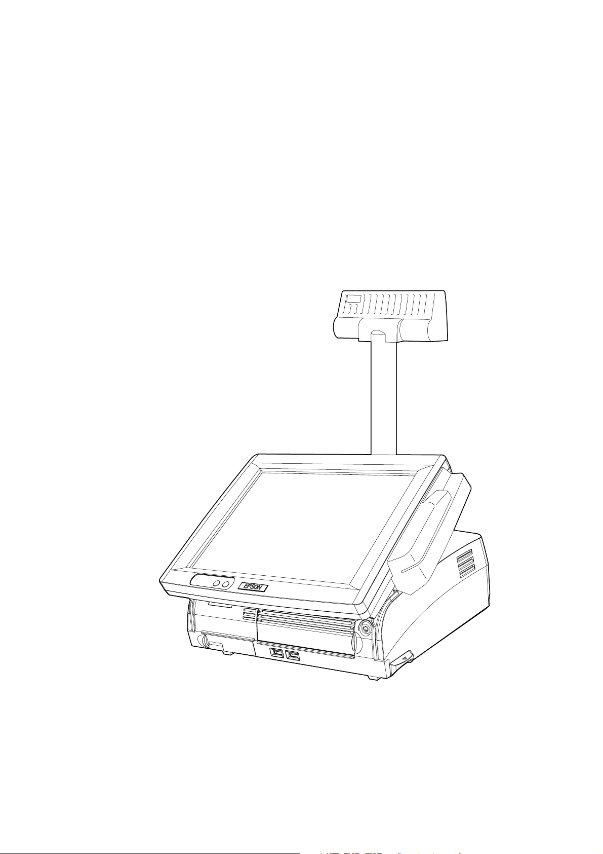
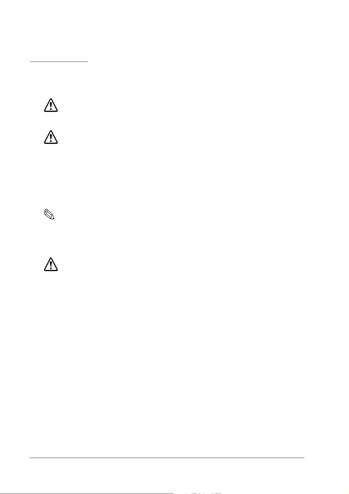
SR-610 is a PC-based POS equipped with a touch panel LCD. This is an the excellent compact
design that will blend into the ambience of your store.
Model configurations
The SR-610 is available in various models, OS, and color. For detailed information, please refer
to our catalog, or contact one of our sales offices.
Rev. C SR-610 System Overview 1-1
Page 20

SR-610 Features
❏ Compact design
• The foot print is 310 mm wide and 306mm deep. It can be placed even where there is
limited counter space.
• The simple design allows the cables to be stored compactly. It can successfully be
installed even in counter setups where the back of the POS is exposed, such as face-toface counters, as it will blend into the ambience of the store.
❏ Easy to use, reliable hardware
• The 12.1 SVGA model uses a high luminance level TFT screen. A touch panel that
minimizes fingerprints is incorporated. Its angle can be adjusted so that it is easy to read,
even in a bright room.
• Three kinds of customer displays are available for various purposes. By changing the
positioning and angle, adjustments can be made so that the customers and the operators
can easily view the display.
• A Magnetic Stripe Reader (MSR) can be attached to the side of the LCD display.
❏ Stable operation and downtime reduction
• RAID1 (mirroring) is supported in models with 2 hard drives installed. Even if one HDD
fails, the other HDD will continue to operate.
• The hard disk can be replaced easily, so maintenance has been improved compared to
the SR-610. This contributes to reduced downtime.
• A CompactFlash (option) is prepared for the data backup.
(It is not possible to boot up from the CompactFlash. Hot-swap during the power is on is
not supported (as before).)
• The unit can be started up using the CD/DVD-ROM drive or a floppy disc drive
connected to the USB port.
• The manager key is used for the optional 60-key POS keyboard (DM-KX060), and up to 7
access levels can be set up, depending on the type of key. Access levels to the system can
be set up by the owner or manager, etc.
❏ High-performance
• The CPU offers power and speed, which is needed for complex programming and data
processing, using a Pentium M/Celeron M and a maximum of 1 GB of memory, using a
HDD larger then 40GB.
• The use of an HDD connected by 2.5" serial ATA helps to improve reliability.
• Windows 2000 Professional SP4, Windows XP Professional SP2 or Windows Embedded
for Point of Service (WEPOS) is used as the OS. Based on OLE-POS, it can be flexibly
applied to a variety of system configurations.
1-2 SR-610 System Overview Rev. C
Page 21

SR-610 Technical Reference Guide
• Equipped with 3 serial ports, a parallel port, 1 PCI slot, and 4 USB ports, extensibility is
assured. Serial ports output +5V (COM 1/2 ports).
❏ Compatibility with Epson's SR-600 series is assured.
• Windows 2000 Professional SP4 is used as the OS. (Windows NT is not supported)
• OPOS ADK is used. If programs are developed through OPOS ADK, you do not have to
make major changes in the whole application, but only the SO part, even if a peripheral
device has been changed.
• The DM-MS123 is used for the MSR.
• The DM-D110/210/500 are used for the customer display.
(DM-D210/500 cannot be used for the SR-610.)
• A CompactFlash adapter (option) is prepared.
Rev. C SR-610 System Overview 1-3
Page 22
Hardware
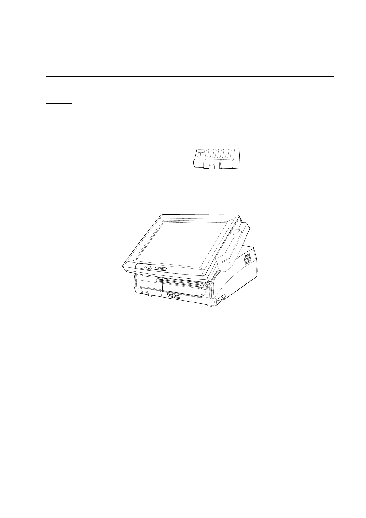
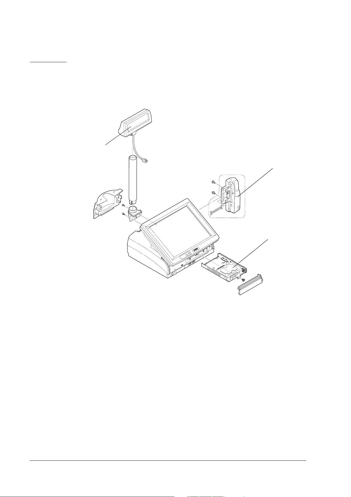
Hardware configurations
SR-610's hardware can be attached to the options as follows - the configuration makes it easy to
replace HDDs.
Customer Display
HDDs
MSR
Difference between PC/AT PC and the SR-610
Compared to PC/AT PCs, the following points are different.
❏ Customer display, and cash drawer can be attached.
❏ LCD unit equipped with a touch panel is integrated.
❏ MSR unit can be mounted on the LCD unit.
❏ Equipped with 3 serial ports, a parallel port, 2 PCI slot, 4 USB ports, extensibility is assured.
Serial ports output +5V(COM 1/2).
1-4 SR-610 System Overview Rev. C
Page 23
Interface
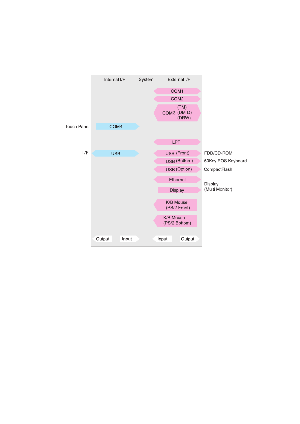
Interface
InterfaceInterface
Interfaces of the SR-610 are as follows:
SR-610 Technical Reference Guide
Rev. C SR-610 System Overview 1-5
Page 24
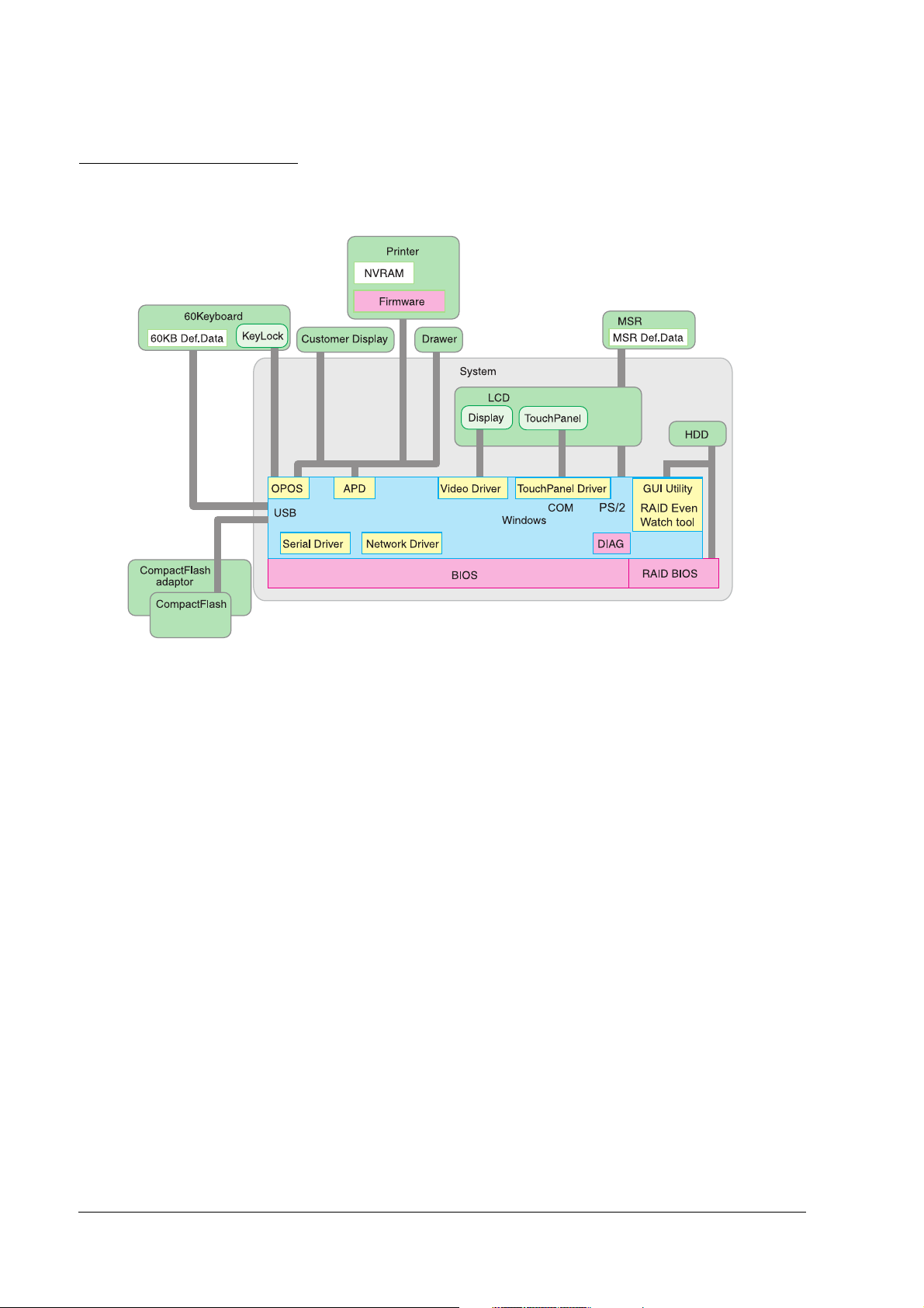
Software configuration
The configuration of the SR-610's software is as follows:
BIOS
BIOS
BIOSBIOS
The BIOS uses the AMI BIOS as a Core BIOS and supports the Plug & Play, APM , ACPI 2.0 etc.
Setting up the BIOS's settings and changes to the CMOS can be performed using a utility. The
default settings can be saved on a floppy disc and loaded on another SR-610 (It is possible only
when the version of the BIOS is the same).
The diagnostic functions (Power On Self Test) inspect the system environment and the hardware
when the power is on.
Device diagnostic utility (DIAG)
The device diagnostic utility can inspect the communication line between devices connecting to
SR-610 and check the setting of main board.
The devices that can be tested are as follows:
• CPU, main board, memory
• HDD
• LCD display and touch panel
• Customer display
1-6 SR-610 System Overview Rev. C
Page 25

SR-610 Technical Reference Guide
The devices that cannot be tested are as follows:
• MSR unit
• PCI card
• USB Access Device (60-key POS keyboard included)
• CompactFlash
Operating system
SR-610 works on the following operating systems.
• Windows 2000 Professional SP4 or later
• Windows XP Professional SP2 or later
• Windows Embedded for Point of Service (WEPOS)
Epson offers HDDs with an OS installed. In addition, a dedicated SR-610 and the utility driver
installation CD-ROM are available as well. Therefore, an OS that the customers bring in can be
used.
Note:
❏ Be sure to back up your data. When you request the repair of an HDD, please be sure to
bring the OS disk.
RAID BIOS/Config utility
Models with 2 HDDs can build RAID1 (mirroring). The RAID BIOS checks the RAID status
during startup, and controls the RAID during operation. Even if one HDD fails during startup
or operation, another HDD can continue to operate the system.
In addition, basic matters such as starting and stopping RAID are executed.
Watch RAID tool (RAID Utility for Windows)
The Watch RAID tool monitors the RAID status during Windows operation. When RAID events
occur, it can notify users by email or buzzer. RAID status can also be confirmed.
RAID Event Watch tool
The RAID Event Watch tool monitors events of the GUI utility. When RAID events occur, it can
display popup messages in front of an application and create event logs for Windows.
OLE-POS
The PC/AT architecture allows the use of tools such as Visual BASIC and Visual C++ when
developing the SR-610 applications. As the OLE-POS drivers are provided for POS peripheral
devices, optimal applications for wide use are easily developed. For the latest OLE-POS, please
Rev. C SR-610 System Overview 1-7
Page 26
contact our sales offices. OPOS drivers vary from the printer driver for general Windows. It is
assumed that the programming is executed in a development environment, such as Visual
BASIC. This driver is not supposed to print through applications on the market.
Printer driver-APD
Adding control of printer, customer display, cash drawer to the printer driver for general
Windows enables the driver to control especially for POS purposes.
Epson Remote Maintenance Software
Epson Remote Maintenance Software
Epson Remote Maintenance SoftwareEpson Remote Maintenance Software
With the Remote Maintenance Software, you can manage clients by issuing various jobs from a
server to clients (SR-610) and obtain the execution results via the internet or LAN system. It
enables you to rewrite or obtain definition data of clients in many shops or on many floors all at
once. You can also rewrite the printer firmware. Therefore, a maintenance person does not need
to go to every client to rewrite data, which makes maintenance more effective.
Options
SR-610 offers the following options.
Hardware Model number
POS Keyboard
Unit
MSR Unit DM-MS123
Customer display DM-D110
CompactFlash adapter OI-S05
60-KeyPOS Keyboard DM-KX060
DM-D210
DM-D500
Operation Testing Products for IR
The Operation Confirmed items are marketed by Epson and are built-in, included, or connected
to an Epson POS product, and operation by has been confirmed by Epson. Epson can also offer
reference information for the selection of peripheral devices to the customer who constructs a
system using Epson POS products. Please inquire what kind of device can be used from Epson
or the selling agent.
This operation confirmation evaluates the equipment in test environments and conditions, but it
does not guarantee the operation. Therefore, procurement and evaluation by the customer are
required.
1-8 SR-610 System Overview Rev. C
Page 27
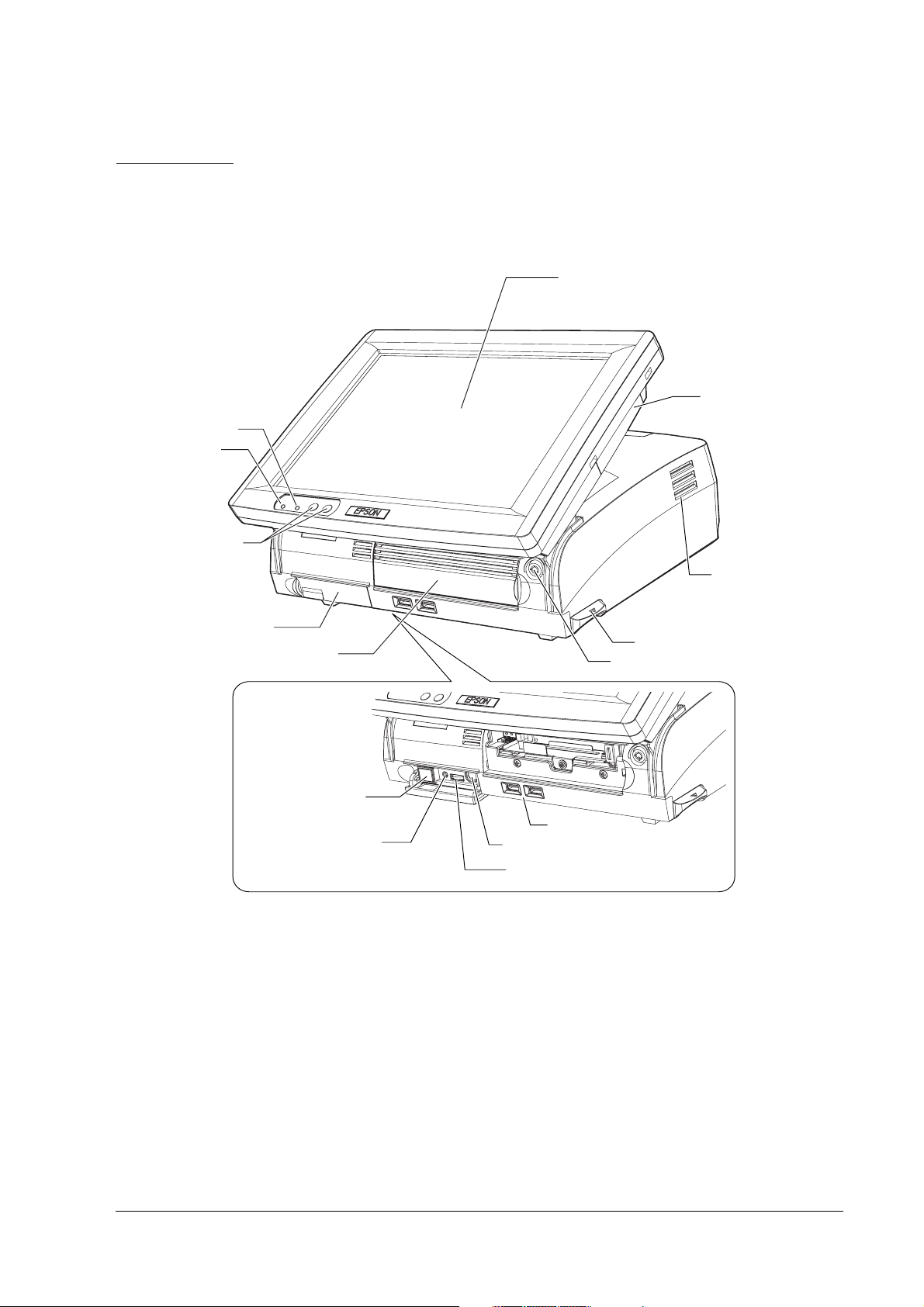
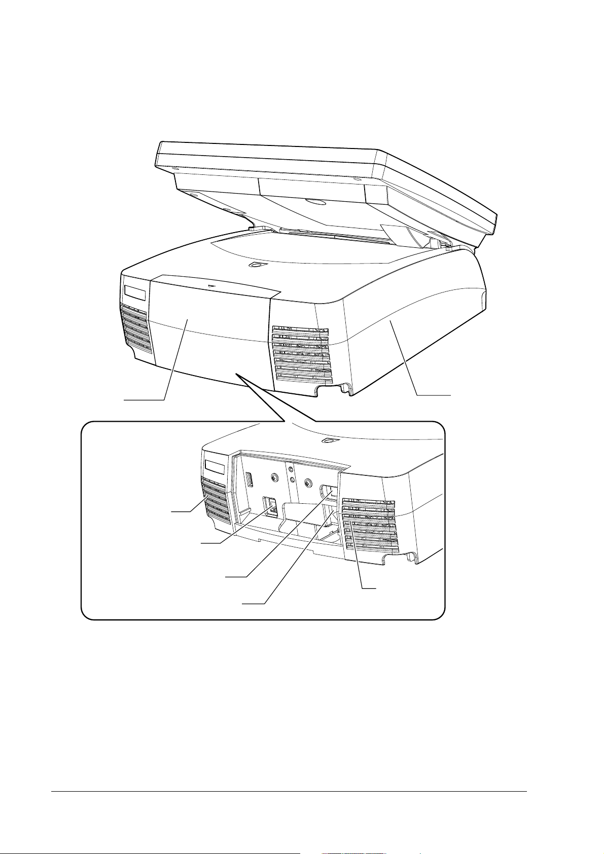
Part Names
The part names are as follows:
HDD LED
Power LED
LCD backlight
brightness
button
SR-610 Technical Reference Guide
LCD unit
MSR cover
Ventilator
Switch cover
Front cover
Front power switch
Reset switch
LCD lever
Case lock key
USB
Keyboard/Mouse(Front)
Speaker volume control knob
Rev. C SR-610 System Overview 1-9
Page 28
Back
Rear cover
Unit cover
Power fan
AC inlet
Main power switch
Case fan
Customer display connector
1-10 SR-610 System Overview Rev. C
Page 29
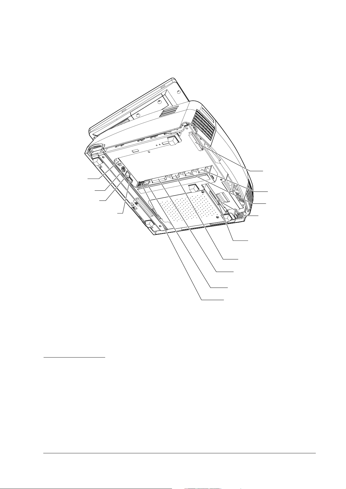
Bottom
Bottom
BottomBottom
Display
Keyboard/Mouse
(Bottom)
Drawer connector
DIP switch
SR-610 Technical Reference Guide
Cable clamp
COM1
COM2
CompactFlash slot
(Option)
SR-610 operation
See the SR-610 users manual.
Eject button
(Option)
COM3
LPT
Ethernet
USB
Rev. C SR-610 System Overview 1-11
Page 30
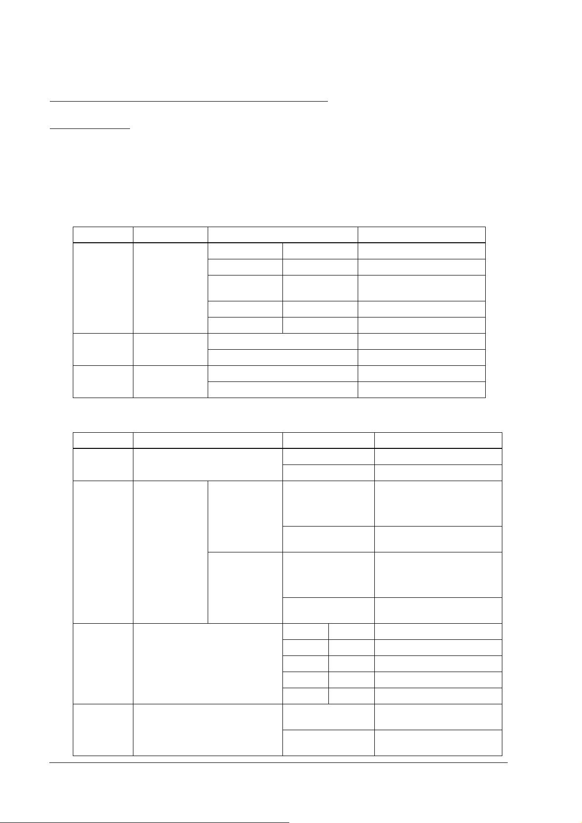
Setting of the DIP
Setting of the DIP SSSSwitch
Setting of the DIP Setting of the DIP
DIP
DIP SSSSwitch
DIP DIP
witches
witchwitch
es
eses
witches
witchwitch
es and the Jumper
eses
and the Jumper
and the Jumper and the Jumper
The DIP Switches are used for the communication with the cash drawer and the for switching
between the front side keyboard/mouse connector and the bottom side keyboard/mouse
connector. SW1 is inside. SW2 is accessible from the outside on the bottom of the unit.
setting
SW1
NO
NO Function
NONO
1,2 Operation mode SW1-1 SW1-2
3 Parity OFF (default) None
4 Data bit length OFF (default) 8Bit
Function Setting
FunctionFunction
OFF OFF Emulation mode 1
ON OFF Emulation mode 2
OFF ON Native mode
ON ON (Reserved)
ON Yes (Even)
ON 7Bit
Setting Contents
SettingSetting
(default)
Contents
ContentsContents
SW2 setting
NO
NO
NONO
1 Handshaking OFF (default) DTR/DSR
2 Meaning of
drawer open
signal
3,4 Transmission speed SW2-3 SW2-4 Function
5 Switching PS/2 OFF Front PS/2 (on VR board)
機能
機能 設定
機能機能
ON XON/XOFF
Emulation mode
1, 2
Native mode OFF( (default) Connects 1 or 2 units of the
OFF (default) Connects 1 or 2 units of the
ON Connects 2 units of the drawer
ON Connects 2 units of the drawer
OFF OFF 9600bps (default)
ON OFF 19200bps
OFF ON 38400bps
ON ON 115200bps
ON (default) Bottom PS/2 (on DRW board)
設定 設定内容
設定設定
drawer (drawer open level: L)
or 1 unit of the drawer (drawer
open level: H)
(drawer open level: H)
drawer (drawer open level: L)
or 1 unit of the drawer (drawer
open level: H)
(drawer open level: H)
enabled
enabled
設定内容
設定内容設定内容
1-12 SR-610 System Overview Rev. C
Page 31

Jumper setting
Jumper setting
Jumper setting Jumper setting
Power supply
unit
SR-610 Technical Reference Guide
DM-D loopback jumper
CPU
DIMM
855GME
CMOS Clear Jumper
LCD type setting jumper
1 2 3
ICH4
CMOS Clear Jumper
It is the jumper to clear the CMOS RAM.
Function
Jumper Address
JP1601 1-2 2-3
Initial Setting CMOS Clean-up
LCD type setting jumper
It is the jumper to set the type of the LCD.
LCD type
LCD type
LCD typeLCD type
Jumper Address
Jumper Address
Jumper AddressJumper Address
JP3101 1-2 2-3 1-2 2-3
JP3102 1-2 1-2 2-3 2-3
(Reserved)
(Reserved) (Reserved)
(Reserved)(Reserved)
(Reserved) (Reserved)
(Reserved)(Reserved)
(Reserved) (SVGA,
(Reserved)(Reserved)
(SVGA, TFT
(SVGA,(SVGA,
TFT))))
TFT TFT
DM-D loopback jumper
The jumper that loops the RTS and CTS of the DM-D connector on the main board.
Function
Jumper Address
JP2901 1-2 2-3
Rev. C SR-610 System Overview 1-13
Loop back No loop back (default)
Page 32

Dimensions
Dimensions
Dimensions Dimensions
The size shown above is for reference and is not guaranteed.
1-14 SR-610 System Overview Rev. C
Page 33

Connected MSR Unit
SR-610 Technical Reference Guide
The size shown above is for reference and is not guaranteed.
Required Clearance
Secure the installation space, and set up on a horizontal area which is wider than the product. Leave a space of 5
cm (2 inches) or more from the wall when setting it up near a wall.
Rev. C SR-610 System Overview 1-15
Page 34

Specifications
❏ SR-610
SR-610
Item Specification
CPU Compatible CPU Intel CeleronM (1.3GHz)
Socket mPGA479M socket
Secondary cache
memory
Memory Main memory 184 pin DDR SDRAM DIMM slot x2, Max. 1 GB
BIOS ROM 8MBit
Chip set Intel 855GME/ICH4 chip set
Video controller Built-in chip set (Supports dual display.)
LCD Size Type 12.1"
Type Color TFT
Resolution 800 ~ 600 dots
Display color 256K (Approx. 260K)
Number of
backlights
Backlight Brightness 272 cd/m
Touch panel Method Resistive film (Data can be entered using the touch panel.)
Surface solidity 3H or more (JIS K-5600, ISO/DIS 15184)
Positioning
accuracy
Fingerprint
resistance
Sub storage HDD HDD Serial ATA interface with 1 or 2 built in-type 2.5" HDD.
512 KB (Built in the CPU.)
(Supports up to DDR DIMM PC2700.)
Note: Operates as Pc2700 when using a DIMM of PC2700 or faster.
2 lights
2
typ. (Touch panel included)
Brightness is adjustable with the backlight brightness buttons.
± 5mm maximum
Supported
RAID-ready for 2 built-in-type (mirroring only)
1-16 SR-610 System Overview Rev. C
Page 35

SR-610 Technical Reference Guide
SR-610
Item Specification
Interface Ethernet
Shared board for
keyboard/mouse
Serial
Parallel x1 (D-sub female 25-pin) Supports EPP/ECP.
Display
USB*4 External: USB 2.0 x4 (high/full/low speed support)
Customer display x1 (RJ-45)
Drawer (DK)*5 x1
Expansion slot PCI slot*6 x1 (DC 3.3 V power supply is provided.) (Revision 2.2)
Sound Beep Can be output to built-in speaker.
Speaker Built-in monaural speaker (with hardware volume control)
BIOS Supports ACPI 2.0/APM 1.2/Plug & Play/DMI.
Supported OS Windows2000 Professional SP4 or later
RTC/CMOS backup battery A lithium non-rechargeable battery supplies the backup voltage to
Power supply AC 100 V ~ 240 V/50 Hz ~ 60 Hz
Temperature Operation: 5°C ~ 35°C
Humidity Operation: 30%RH ~ 80%RH (No condensation)
Case color EPSON cool white (ECW)/EPSON dark gray (EDG)
Overall dimensions 310mm(W) x 363mm(D) x 277mm(H)
Mass 8.7kg (LCD unit and Two-hard-disks included)
*1
10 BASE-T/100 BASE-TX is included as standard.
Wake On LAN available
x2 PS/2-compliant (6-pin mini-DIN)
Either the front connector or the bottom connector is available.
Can be switched with the DIP switch.
Both keyboard and moue can be connected using branch cable.
*2
x3 (D-sub male 9-pin)
Can be set in the BIOS settings so that it outputs DC5 V to pin 1 through
COM1 and COM2.
COM3 can be set in the BIOS settings to be used as Normal, TM/DM-D,
DRW, DM-D port.
*7
Supports Wake up function (Modem Ring On) of pin 9 (RI).
*3
x1 (D-sub female 15-pin)
Internal: x1
WindowsXP Professional SP2 or later
Windows
Embedded for Point of Service
the RTC.
Max. 4.0 A/152 W
Storage: -10°C ~ 50°C
Storage: 30%RH ~ 90%RH (No condensation)
(Rear cover included, LCD unit excluded)
Rev. C SR-610 System Overview 1-17
Page 36

NOTE*1: Ethernet controller/sound controller are included in the standard package, and are separable in the BIOS
settings.
*2: The SR-610 has 4 external ports. However, the customer display uses 1 port, leaving 3 ports available for
external interfaces.
*3: Contents can be displayed separately on the display and LCD using the dual display function.
*4: In addition to four external ports, the SR-610 has one other USB port for connecting the CompactFlash
adapter of the option.
*5: Two drawers can be controlled by the exclusive cable.
*6: When attaching the CompactFlash adapter of the option, the PCL slot cannot be used.
*7: COM3 can be set in the BIOS as shown in the table below.
BIOS setting
Versatile device TM printer
Normal Y
TM/DM-D(*9) N Y
DRW/DM-D N N Y Y
Y: Settable, N: Not settable
*8: Can be used in the same manner as COM1 and COM2 are. (However, +5 V cannot be output to pin 1
(DCD terminal).)
COM3 port
(*8)
YNN
(*10)
Customer
display DM-D
YN
Cash drawer
DRW
*9: In the TM/DM-D mode, use the SR-610 connected with both the TM printer and the customer display.
*10: As COM3 becomes the exclusive port for the TM printer, it cannot be used for the other devices.
❏ 60-key POS Keyboard
DM-KX060
Item DM-KX060
Key switch Alignment 6 x 10
Number of keys 60
Keylock 8 positions
Interface Connector for connecting to the
main unit
USB downstream x2 USB 1.1 compliant
Overall dimensions 250mm(W) x 140mm(D) x 52mm(H)
Cable length 550mm
Mass Approx. 800 g
USB 1.1 compliant Type A connector
1-18 SR-610 System Overview Rev. C
Page 37

SR-610 Technical Reference Guide
❏ MSR Unit
DM-MS123
Item DM-MS123
Supported card ISO 7811/JIS X6301 Type I, track 1, 2, 3
Connection Can be connected to the side of the LCD unit with a
Power supply DC 5 V (Supplied from the SR-610.)
Overall dimensions 46mm(W) x 174mm(D) x 56mm(H)
Mass Approx. 270 g
CompactFlash Adapter
❏
dedicated connector.
OI-S05
Item OI-S05
Usable card
BIOS BIOS version 3.05 or higher.
Mass Approx. 75 g
CompactFlash
Type I(3.3mm thick)/Type II(5mm thick)
CF+ Card
Type I(3.3mm thick)/Type II(5mm thick)
The I/O card of the CF+Card (modem, LAN, etc), the Longer card and
the Extended card (the full length exceeds 36.55 mm) are not
supported.
It is not possible to boot up from the CompactFlash.
Hot-swap during the power is on is not supported (as before).
Set [Boot]-[Onboard CompactFlash] to "Disabled".
Rev. C SR-610 System Overview 1-19
Page 38

1-20 SR-610 System Overview Rev. C
Page 39

SR-610 Technical Reference Guide
Chapter 2
OS and Drivers
Outline of This Chapter
This chapter tells which Operating Systems and Drivers can be used and how to install and
uninstall them.
CAUTION:
Don’t write anything, such as an application to an HDD that is removed from the SR-610.
The vibration and impact can cause trouble and the failure of the HDD.
Operating Systems
The following Operating Systems can be used for the SR-610.
❏ Windows 2000 Professional SP4 (There is a version preinstalled by EPSON)
❏ Windows XP Professional Edition SP2 (There is a version preinstalled by EPSON)
❏ Windows Embedded for Point of Service (WEPOS)
(There is a version preinstalled by EPSON)
Drivers and Utilities
Drivers for using the SR-610 are on the Driver CD-ROM included with the SR-610. If the
operating system is pre-installed on the HDD, the printer driver, the customer display driver,
and the ERM are not installed.
Rev. C OS and Drivers 2-1
Page 40

Driver CD-ROM for the SR-610
In case you use a locally procured OS on the SR-610, the drivers for using the peripheral devices
are on this CD-ROM.
The CD-ROM directory is shown below.
Root CDVER.TAG
|--- COMMON Common OS utility drivers
| |--- 60KEYCFG : 60-key POS keyboard definition utility
| |--- MSRCFG : MSR definition utility
| |--- APDRV : Advanced Printer driver
| |--- ERM : Epson Remote Maintenance Software
| |--- OPOSADK : OPOS ADK(Printer, Customer Display and Drawer)
|--- DOS62 Drivers for MS-DOS
| |--- NETWORK : Network drivers
|--- WIN2K Drivers for Windows2000
| |--- 60KEYCFG : 60-keyPOSkeyboard driver
| |--- CHIPSET : Chipset drivers
| |--- DISSW : Power button prohibited setting tool
| |--- EPSERIAL : Serial Driver
| |--- NETWORK : Network drivers
| |--- SATARAID : SATA RAID related driver folder
| | |--- DRIVER : SATA-RAID Driver
| | |--- TOOL : GUI Utility, RAID Event Monitoring Tool
| |--- TOUCH : Touch Panel drivers
| |--- VIDEO : Video drivers
|--- WINXP Drivers for Windows XP
|--- 60KEY : 60-key POS Keyboard drivers
|--- CHIPSET : Chipset drivers
|--- EPSERIAL : Serial tool
|--- NETWORK : Network drivers
|--- SATARAID : SATA RAID related driver folder
| |--- DRIVER : SATA-RAID Driver
| |--- TOOL : GUI Utility, RAID Event Monitoring Tool
|--- TOUCH : Touch Panel drivers
|--- VIDEO : Video drivers
Readme.txt files are in both the root directory and in subdirectories of the root directory.
1. The Readme.txt file in the root directory contains an overview of this CD-ROM and
refers to the Readme.txt files in the various subdirectories.
2. The Readme.txt files in the operating system subdirectories explain driver installation/
un-installation for each operating system.
3. Readme.txt files for KEYCFG, OPOS-ADK, and APDRV are included with the software.
2-2 OS and Drivers Rev. C
Page 41

SR-610 Technical Reference Guide
Windows 2000 Pre-Installed Model
The exclusive EPSON utility and drivers for using SR-610 are pre-installed in the HDD with the
pre-installed Windows 2000 Professional.
Installation Procedure
Windows 2000 Installation
When the power supply is turned on, the installation starts. Enter the product
key of the W2K label pasted on the product. You can set up the Network
automatically or set it up later.
Change of Double click settings
Set up this setting every time a new user starts using Windows 2000.
Setting of RAID
If there are 2 installed HDDs and you are going to use a RAID system, set it
up.
Other software Installation
Install utilities such as serial driver, MSR, and 60-key from backup folder if
necessary.
Rev. C OS and Drivers 2-3
Page 42

Formatting the hard disk
The hard disk is composed of one partition of up to 10 GB as a system area. For a hard disk of
more than 10 GB, the excess area other than the system area is not yet formatted. This drive can
be converted to NTFS using the Convert command. Use the disk administrator when creating a
drive in the unused area. The start-up drive has been formatted to the following file system.
• File system: FAT32
• Volume label: Windows 2000
Pre-installed software
❏ Microsoft Windows 2000 Professional
❏ Microsoft Windows 2000 Service Pack 4
❏ Microsoft Windows 2000 Multilingual User Interface Pack
❏ Intel Chipset software installation utility
❏ Intel Video driver
❏ Intel Network driver
❏ Silicon Image SATA-RAID driver
❏ EPSON Touch Panel driver
❏ EPSON Power button prohibited setting tool*1
❏ EPSON 60-key POS keyboard definition utility *1
❏ EPSON MSR definition utility *1
❏ EPSON Serial driver *1
Note:
*1: These are not installed during the auto installation procedure.
2-4 OS and Drivers Rev. C
Page 43

SR-610 Technical Reference Guide
Version of the Pre-installation HDD
To confirm the version of the HDD, see the file HDVER.TAG in the root directory of the boot
drive. This file is text-formatted and can be read using Notepad or a similar text editor. The file
HDVER.TAG has the following contents:
[HD Informatio n]
MODEL=SR-610
OS=Windows2000
LANG=Dutch/English/French/German/Italian/Portuguese/Russian/Spanish
VER=1.**.*
Directory Configuration
The root directory of the HDD is structured as follows.
|--- Backup
| |--- 60KEYCFG : 60-key POS keyboard definition utility
| | |--- DRIVER : 60-key POS keyboard driver
| | |--- TOOL : Utility
| |--- CHIPSET : Chipset driver backup folder
| |--- EPSERIAL : EPSON Serial driver backup folder
| |--- DISSW : EPSON Power button prohibited setting tool backup folder
| |--- Msrcfg : MSR definition utility backup folder
| |--- NETWORK : Network driver backup folder
| |--- SATARAID : SATA RAID related driver backup folder
| | |--- DRIVER : SATA-RAID driver
| | |--- TOOL : GUI Utility, RAID Event Monitoring Tool
| |--- TOUCH : Touch Panel driver backup folder
| |--- VIDEO : Video driver backup folder
|--- I386 : Setup file folder
|--- Mui : Microsoft Windows XP Multilingual User Interface Pack
|--- Program Files : Windows utility folders
|--- WINNT : Windows folders
The I386 directory may be deleted after the addition of the Windows 2000 application and the
addition / change of the driver.
The directories under the Backup directory are the backups for drivers and utilities. Each of
these directories can be backed up into CD-R or other media. After being backed up, these
directories may be deleted.
If you install the optional CD-R/RW drive, you need to get software for CD-R/RW writing. The
software is not supplied by EPSON.
Rev. C OS and Drivers 2-5
Page 44

Windows 2000 Setup Procedure
Note
Connect the keyboard before beginning the setup procedure. The keyboard is necessary for inputting the
product ID and the password.
Windows 2000 is set up by using the following procedure.
1. Turn on the system, and boot the system from the pre-installation HDD. Windows 2000
setup will start.
2. The License Agreement screen is displayed. Check the contents, then select [I accept this
agreement] and click Next.
3. The Regional Settings screen is displayed. Make sure the system locale, user locales and
keyboard layout are set to United States, then click Next.
4. The Personalize Your Software screen is displayed. Input the Name and Organization, then
click Next.
5. The Your Product Key screen is displayed. Input the product key entered on the cover of the
First Step Guide in the COA (Certificate of Authenticity) package included with this
product; then click Next.
6. The Computer Name and Administrator Password screen is displayed. Input the Computer
Name and Administrator Password, then click Next.
7. The Date and Time Settings screen is displayed. Set the date and time, then click Next.
8. The Networking Settings screen is displayed. Select either Typical Settings or Custom
Settings according to the environment, then click Next. The Networking Components screen
is displayed if Custom Settings is selected. Set the settings in accordance with the
environment, then click Next.
9. The Workgroup or Computer Domain screen is displayed. Set the settings in accordance
with the environment, then click Next.
10. The system will start automatically when Restart is clicked.
11. The Network Identification Wizard starts. Click Next.
12. The Users of this Computer screen is displayed. Set the settings in accordance with the
environment, then click Next.
13. The Completing the Network Identification Wizard screen is displayed. Click Finish.
14. Windows 2000 starts and the setup is completed.
2-6 OS and Drivers Rev. C
Page 45

SR-610 Technical Reference Guide
Setting the recognition range of the double click
When Windows 2000 is installed, the permissible double click level is limited and it is difficult to
double click with your finger. To change the permissible double click level, start up the EPSON
Touch Panel Configuration Tool. It changes the registry key automatically. This setting makes
easy to double click with your finger.
However, when a new user first logs on, the permissible level is limited because the default
value of Windows is the value of the registry key. So the registry key must be modified for
individual users.
When Windows 2000 is set up and a new user is created, the registry key must be modified for
individual users by following the steps below.
Note
The administrator modifies the registry key.
Method
Select Programs - Epson Touch Panel Tool - Touch Panel Configuration Tool from the Start
menu. Click OK. (There is no need to do any other operation.)
Various Configurations (Windows 2000)
To change their configurations, use the control panel.
Setting the Network
A dialog box prompting the user to manually install the network is displayed. Set the network
settings by the following procedure.
1. Open the Control Panel, then select Network and Dial-up Connections.
2. The Network and Dial-up Connections dialog box is displayed. Select Make New
Connection.
3. The Network Connection Wizard starts. If the location information setting has not been
completed by this time, the Location Information dialog box is displayed at this time. Set the
settings in accordance with the environment, then click OK. If all the location information
has been set, this dialog box is not displayed. Proceed to item (5) and set the settings in
subsequent steps.
4. The Telephone and Modem Option dialog box is displayed. Select the location set in the
previous item, then click OK.
5. The Network Connection Wizard opening dialog box is displayed. Click Next.
Rev. C OS and Drivers 2-7
Page 46
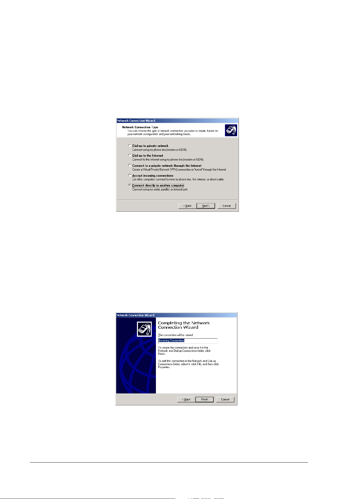
6. The Network Connection Type dialog box is displayed. Set the settings in accordance with
the environment; then click Next. The dialog displayed by the following procedure is
different depending on the type of the set network connection. The explanation here is for
the case in which Connect directly to another computer is selected. Setting of other network
connections can be accomplished in the same way by following instructions of the Network
Connection Wizard.
7. The Host or Guest dialog box is displayed. Set the settings in accordance with the
environment, then click Next. The explanation here is for the case in which Host is selected.
8. The Connection Device dialog box is displayed. Set the settings in accordance with the
environment, then click Next.
9. The Allowed Users dialog box is displayed. Set the settings in accordance with the
environment, then click Next.
10. The Completing the Network Connection Wizard dialog box is displayed. Input the name to
be given to the current settings, then click Finish.
11. The newly set connection is added to the Network and Dial-up Connection dialog box. To
change the connection method, right click on the newly added icon, and select Properties.
The settings can then be changed.
2-8 OS and Drivers Rev. C
Page 47

SR-610 Technical Reference Guide
EPSON Serial Driver
Install
Install
InstallInstall
Uninstall
Uninstall
UninstallUninstall
Serial Driver
Serial Driver Serial Driver
When the serial port is transmitting with Windows 2000, this Driver prevents the OS from
shifting to the Standby mode, and the operation of the full-on mode can be continued.
When installing the service pack, install the serial driver again.
Note
Be sure an administrator installs the serial driver.
Install the serial driver using the following procedure.
1. Execute C:\backup\epserial\Epserial.exe.
2. Start serial driver Setup. The welcome screen is displayed. Click Next.
3. After installation is completed, the InstallShield Wizard Complete dialog box is displayed.
Select Yes, I want to restart my computer now, then click Finish to restart the system.
Uninstall the serial driver using the following procedure.
1. Open the Control Panel and select Add/Remove Programs.
2. The Add/Remove Programs dialog box is displayed. Click Change or Remove Programs to
display a list of the currently installed programs. Change/Remove will be displayed when
EPSON Serial Driver is selected. Click Change/Remove.
3. The Confirm File Deletion dialog box is displayed. Click Ye s.
4. The Remove Programs From Your Computer dialog box is displayed. The uninstall process
then begins.
5. A dialog box is displayed when uninstall is completed. Click OK.
Power button prohibited setting tool for windows 2000
The Power button prohibited setting tool is the tool setting the registry to prohibit the shift to the
shutdown and the stand-by mode even if the front power switch is pressed. It can prevent the
shutdown of the system even if the front power switch is pressed by mistake.
Note
Note for using
Note Note
for using
for usingfor using
When Power Options of Windows are updated, the setting is cleared, so always set after
updating the Power Options.
for windows 2000
for windows 2000for windows 2000
Rev. C OS and Drivers 2-9
Page 48

How to us
How to useeee
How to usHow to us
1. Execute C:\Backup\Dissw\DISSW.EXE.
2. The following message is displayed. Click Yes. If No is clicked, processing stops and you
return to Windows.
3. When setting the registry, the following message is displayed. Click Yes, so Windows is
restarted and the setting becomes valid.
If you click No, the setting returns to Windows without becoming valid. In this case, if you
then restart Windows, the setting becomes valid.
Dual Display
If an external monitor is added, the SR-610 can display the same content on both the LCD
display and the external monitor, or each of them can display different content (expansion of the
work area).
Displaying the same content on both monitors
Follow the following procedure.
1. Select [Start]-[Settings]-[Control Panel]-[Display]
2-10 OS and Drivers Rev. C
Page 49

SR-610 Technical Reference Guide
2. The [Display Properties] screen is displayed. Select the [Settings] tab and press the
[Advanced] button.
3. The following screen is displayed. Select the [Intel(R) Extreme Graphics 2 for Mobile] tab
and press the [Graphics Properties] button.
Rev. C OS and Drivers 2-11
Page 50

4. The [Intel(R) Extreme Graphics 2 for mobile] screen is displayed. Select the [Display
Devices] button and then
5. The [Confirm the Desktop Change] screen is displayed. Press the [OK] button.
check the [Intel(R) Dual Display Clone], and press the [OK] button.
6. Each monitor displays the same content.
2-12 OS and Drivers Rev. C
Page 51

SR-610 Technical Reference Guide
Displaying different content on each monitor (expansion of the work area)
Follow the following procedure.
1. Select [Start]-[Settings]-[Control Panel]-[Display]
2. The [Display Properties] screen is displayed. Select the [Settings] tab and press the
[Advanced] button.
3. The following screen is displayed. Select the [Intel(R) Extreme Graphics 2 for Mobile] tab
and press the [Graphics Properties] button.
Rev. C OS and Drivers 2-13
Page 52

4. The [Intel(R) Extreme Graphics 2 for Mobile] screen is displayed. Select the [Display
Devices] button and then
5. Change the method of allocating the work area by dragging and dropping the icons of the
monitors.
check the [Extended Desktop] button, and press the [OK] button.
2-14 OS and Drivers Rev. C
Page 53

SR-610 Technical Reference Guide
6. Press the [Display Settings] button. Change the setting of each monitor, and press the [OK]
button.
7. The [Confirm Desktop Change] screen is displayed. Press the [OK] button.
Adding Windows 2000 Applications
When adding any Windows 2000 application, specify the C:\I386 directory. In this directory,
\I386 has been backed up from the Windows 2000 DVD-ROM.
Rev. C OS and Drivers 2-15
Page 54

Support Information
Right click the My Computer icon and select Properties from the pull down menu. Then the
System properties are displayed.
Click the Support information button, so the information on the contact is displayed
2-16 OS and Drivers Rev. C
Page 55

SR-610 Technical Reference Guide
Recovering the OS
Preparing confirmation
Preparing confirmation
Preparing confirmationPreparing confirmation
Confirm the following before OS recovery.
❏ DVD-ROM drive is prepared by the user.
❏ "The Windows 2000 DVD-ROM" included with the product is used for recovering Windows
2000.
❏ In the model installed 2 HDDs, construct RAID first, then perform OS recovery to construct
RAID.
❏ Use the HDD included in the shipment or an unused HDD for OS recovery.
❏ The external keyboard is necessary for the recovery.
❏ In the setup of OS after recovering the OS, it is necessary to enter the product ID. In EPSON
OS pre-installed model, the product ID is printed on the Windows sticker label on the side of
the system.
❏ Set the BIOS setting to "Optimal Defaults". When using the customized BIOS setting, note
down the BIOS setting value beforehand. After the recovery is done, you must reset it to that
value.
❏ OS recovery erases all contents of the HDD. Back up the necessary data to a floppy disk or
other media.
Recovering method
Recovering method
Recovering methodRecovering method
Follow the steps below to carry out OS recovery.
1. Turn power to the SR-610 off. Pull out the power cord from the SR-610.
2. Remove the peripheral devices such as the CompactFlash card that is not needed in the
recovery work.
3. Install the HDD unit for which OS recovery will be done to the SR-610. For single HDD
model, install it on the front side.
CAUTION:
Confirm that the HDD is installed correctly and that the cable are connected properly. It
is important to prevent cause a poor connection.
4. Connect the external keyboard to the SR-610 keyboard/mouse connector and connect the
DVD-ROM Drive to the USB connector.
5. Connect the power cord to the SR-610 and power switch On.
6. Boot the system, press the Del key during the POST process, and the BIOS setup will start.
Rev. C OS and Drivers 2-17
Page 56

7. To set the BIOS to Optimal Defaults, execute Load Optimal Defaults in the Exit menu.
8. Set to the DVD-ROM model number connecting 1st Boot Device of Boot Device Priority in
the Boot menu.
9. Set the USB 2.0 ControllerMode to Hispeed in the Advanced menu.
10. Select "Save Changes and Exit" in the Exit menu, and press the Enter key. The following
dialog box is displayed.
Save configuration changes and exit setup?
[OK] [Cancel]
11. Select [OK], and press the Enter key.
12. The system will reboot. Insert the "Windows 2000 DVD-ROM" into the DVD-ROM drive.
13. The following message will appear. Select and enter the partition size of the HDD.
Please select the system partition size.
1: 10GB (Default size)
F: Full size of HD.
Please push a key of 1 or F. _
14. Select the range to format as the system area on the hard disk. Press the "1" key to select
10GB or press the "F" key to select the full size. After that, the OS recovery starts.
15. When the prompt below is displayed on the screen, OS recovery work is complete.
c:\RESTORE>_
16. Eject the "Windows 2000 DVD-ROM" from the DVD-ROM drive.
17. Reboot and start the BIOS setup utility.
18. Set USB 2.0 ControllerMode to Full Speed in the Advanced menu.
19. Set to the HDD model number connecting 1st Boot Device of Boot Device Priority in the Boot
menu.
20. Select "Save Changes and Exit" in the Exit menu, and press the Enter key. The following
dialog box is displayed.
Save configuration changes and exit setup?
[OK] [Cancel]
21. Select [OK], and press the Enter key.
Detach the external keyboard.Limitation
❏ Recovery cannot be performed starting from a hard disk. You must perform recovery from a
DVD-ROM.
2-18 OS and Drivers Rev. C
Page 57

SR-610 Technical Reference Guide
Windows XP Pre-Installed Model
The exclusive EPSON utility and drivers for using SR-610 are pre-installed in the HDD with the
pre-installed Windows XP Professional.
Installation Procedure
Windows XP Installation
When the power supply is turned on, the installation starts. Enter the product
key of the WXP label pasted on the product. You can set up the Network
automatically or set it up later.
Change of Double click settings
Set up this setting every time a new user starts using Windows XP.
Setting of RAID
If there are 2 installed HDDs and you are going to use a RAID system, set it
up.
Other software Installation
Install utilities such as serial driver, 28-key, MSR, and 60-key from backup
folder if necessary.
Activation
Authenticate the license by the network or by telephone.
Rev. C OS and Drivers 2-19
Page 58

Formatting the hard disk
The hard disk is composed of one partition of up to 10 GB as a system area. For a hard disk of
more than 10 GB, the excess area other than the system area is not yet formatted. This drive can
be converted to NTFS using the Convert command. Use the disk administrator when creating a
drive in the unused area. The start-up drive has been formatted to the following file system.
• File system: NTFS
• Volume label: Windows XP
Pre-installed software
❏ Microsoft Windows XP Professional
❏ Microsoft Windows XP Service Pack 2
❏ Microsoft Windows XP Multilingual User Interface Pack
❏ Intel Chipset software installation utility
❏ Intel Video driver
❏ Intel Network driver
❏ Silicon Image SATA-RAID driver
❏ EPSON Touch Panel driver
❏ EPSON 60-key POS keyboard definition utility*1
❏ EPSON MSR definition utility*1
❏ EPSON Serial driver *1
Note:
*1: These are not installed during the auto installation procedure.
2-20 OS and Drivers Rev. C
Page 59

SR-610 Technical Reference Guide
Version of the Pre-installation HDD
To confirm the version of the HDD, see the file HDVER.TAG in the root directory of the boot
drive. This file is text-formatted and can be read using Notepad or a similar text editor. The file
HDVER.TAG has the following contents:
[HD Informatio n]
MODEL=SR-610
OS=WindowsXP OEM
LANG=Dutch/English/French/German/Italian/Portuguese/Russian/Spanish
VER=1.**.*
Directory Configuration
The root directory of the HDD is structured as follows.
|--- Backup
| |--- 60KEYCFG : 60-key POS keyboard definition utility backup folder
| | |--- DRIVER : 60-key POS keyboard driver
| | |--- TOOL : Utility
| |--- CHIPSET : Chipset driver backup folder
| |--- EPSERIAL : EPSON Serial driver backup folder
| |--- MSRCFG : MSR definition utility backup folder
| |--- NETWORK : Network driver backup folder
| |--- SATARAID : SATA RAID related driver backup folder
| | |--- DRIVER : SATA-RAID driver
| | |--- TOOL : GUI Utility, RAID Event Monitoring Tool
| |--- TOUCH : Touch Panel driver backup folder
| |--- VIDEO : Video driver backup folder
|--- I386 : Setup file folder
|--- Mui : Microsoft Windows XP Multilingual User Interface Pack
|--- Program Files : Windows utility folders
|--- WINNT : Windows folders
The I386 directory may be deleted after the addition of the Windows XP application and the
addition / change of the driver.
The directories under the Backup directory are the backups for drivers and utilities. Each of
these directories can be backed up into CD-R or other media. After being backed up, these
directories may be deleted.
If you install the optional CD-R/RW drive, you need to get software for CD-R/RW writing. The
software is not supplied by EPSON.
Rev. C OS and Drivers 2-21
Page 60

Windows XP Setup Procedure
Note
After connecting the keyboard, start the setup procedure. The keyboard is necessary for inputting the
product ID and the password.
Windows XP is set up by using the following procedure.
1. Turn on the system, and boot the system from the pre-installation HDD. Windows XP setup
will start.
2. The [Welcome to the Windows XP Setup Wizard] screen is displayed. Click Next.
3. The License Agreement screen is displayed. Check the contents, then select [I accept this
agreement] and click Next.
4. The [Regional and Language Options] dialog box is displayed. Confirm the setting contents
and click Next
5. The [Personalize Your Software] dialog box is displayed. Input your name and your
organization, and then click Next
6. The [Your Product key] dialog box is displayed. Input the 25-digit product key shown on the
COA (Certificate of Authenticity) and click Next
Next.
NextNext
Next.
NextNext
Next.
NextNext
7. The [Computer Name and Administrator Password] dialog box is displayed. Input the
necessary information and click Next
8. The [Date and Time Settings] dialog box is displayed. Confirm the setting and click Next
9. The Networking Settings screen is displayed. Select either Typical Settings or Custom
Settings according to the environment, then click Next. The Networking Components screen
is displayed if Custom Settings is selected. Set the settings in accordance with the
environment, then click Next.
10. The Workgroup or Computer Domain screen is displayed. Set the settings in accordance
with the environment, then click Next.
11. The [Completing the Windows XP setup wizard] dialog box is displayed. Click Finish
Next.
NextNext
Setting the recognition range of the double click
When connecting the LCD with the touch panel and making a setup, the touch panel driver is
automatically installed and the double click setting registry key of Windows is modified.
But when a new user first logs on, the default value of Windows is applied to the value of the
registry key, so the registry key must be modified for individual users.
When you set up Windows XP and create a new user, you have to modify the registry key for
individual users by following the steps below.
Next.
NextNext
Finish.
FinishFinish
Note
The administrator modifies the registry key.
2-22 OS and Drivers Rev. C
Page 61

SR-610 Technical Reference Guide
EPSON Serial Driver
When the serial port is transmitting with Windows XP, this Driver prevents the OS from shifting
to the Standby mode, and the operation of the full-on mode can be continued.
Install
Install
InstallInstall
Note
Be sure an administrator installs the serial driver.
Install the serial driver using the following procedure.
1. Execute C:\BACKUP\EPSERIAL\EPSERIAL.exe.
2. Start serial driver Setup. The welcome screen is displayed. Click Next.
3. After installation is completed, the InstallShield Wizard Complete dialog box is displayed.
Select Yes, I want to restart my computer now, then click Finish to restart the system.
Uninstalling the serial port driver
Uninstall the serial port driver using the following procedure.
1. Open the Control Panel, and select Add or Remove Programs.
2. The Add or Remove Programs dialog box is displayed. Click Change or Remove Programs
to display a list of the currently installed programs. Change/Remove will be displayed
when EPSON Serial Driver is selected. Click Change/Remove.
3. The Confirm File Deletion dialog box is displayed. Click OK.
Rev. C OS and Drivers 2-23
Page 62

Dual Display
If an external monitor is added, the SR-610 can display the same content on both the LCD
display and the external monitor, or each of them can display different content (expansion of the
work area).
Displaying the same content on both monitors
Follow the following procedure.
1. Select [Start]-[Control Panel]-[Appearance and Themes]-[Display]
2. The [Display Properties] screen is displayed. Select the [Settings] tab and press the
[Advanced] button.
3. The following screen is displayed. Select the [Intel(R) Extreme Graphics 2 for Mobile] tab
and press the [Graphics Properties] button.
2-24 OS and Drivers Rev. C
Page 63

SR-610 Technical Reference Guide
4. The [Intel(R) Extreme Graphics 2 for mobile] screen is displayed. Select the [Display
Devices] button and then
check the [Intel(R) Dual Display Clone], and press the [OK] button.
5. The [Confirm the Desktop Change] screen is displayed. Press the [OK] button.
6. Each monitor displays the same content.
Rev. C OS and Drivers 2-25
Page 64

Displaying the different content with each monitor (The expansion of the work area)
Follow the following procedure.
1. Select [Start]-[Control Panel]-[Appearance and Themes]-[Display].
2. The [Display Properties] screen is displayed. Select the [Settings] tab and press the
[Advanced] button.
3. The following screen is displayed. Select the [Intel(R) Extreme Graphics 2 for Mobile] tab
and press the [Graphics Properties] button.
2-26 OS and Drivers Rev. C
Page 65

SR-610 Technical Reference Guide
4. The [Intel(R) Extreme Graphics 2 for Mobile] screen is displayed.Select the [Display Devices]
button and then
check the [Extended Desktop] button, and press the [Apply] button.
5. Change the method of allocating the work area by dragging and dropping the icons of the
monitors.
Rev. C OS and Drivers 2-27
Page 66

6. Select the [Display Settings] button. Change the setting of each monitor, and press the [OK]
button.
7. The [Confirm the Desktop Change] screen is displayed. Press the [OK] button.
Adding Windows XP Applications
When adding any Windows XP application, specify the C:\I386 directory. In this directory,
\I386 has been backed up from the Windows XP DVD-ROM.
Activation
The copy prevention technology for softwares called Product Activation (hereafter referred to as
License authentication) is used in Windows XP. Thus, license authentication is required to
reinstall or recover the OS.
The following is the procedure for the license authentication.
1. Turn on the power of SR-610.
2-28 OS and Drivers Rev. C
Page 67

SR-610 Technical Reference Guide
2. The following message is displayed on the lower right of the screen shortly after Windows
XP starts up. Click the icon.
3. Windows license authentication screen is displayed."Select Yes, let's activate Windows over
the Internet now" or "Yes, I want to telephone a customer service representative to activate
Windows", and click the [Next] button.
4. Follow the instructions on the screen, and complete the license authentication procedure.
Note:
If the license authentication is not carried out, you will not be able to use XP after expiration. Thus, be
sure to carry it out when the OS is installed.
Rev. C OS and Drivers 2-29
Page 68

Recovering the OS
Preparing confirmation
Preparing confirmation
Preparing confirmationPreparing confirmation
Note:
Disconnect the mouse before recovering the OS. If the mouse is connected, this will not work
Confirm the following before OS recovery.
❏ DVD-ROM drive is prepared by the user.
❏ "The Windows XP DVD-ROM" included with the product is used for recovering Windows
XP.
❏ In the model with 2 installed HDDs, construct the RAID first, then perform OS recovery to
construct the RAID.
❏ Use the HDD included in the shipment or an unused HDD for OS recovery.
❏ The external keyboard is necessary for the recovery.
❏ In the setup of OS after recovering the OS, it is necessary to enter the product ID. The
product ID is printed on the Windows sticker label on the bottom of the system.
❏ Set the BIOS setting to "Optimal Defaults." When using the customized BIOS setting, note
down the BIOS setting value beforehand. After the recovery is done, you must reset it to that
value.
❏ OS recovery erases all contents of the HDD. Back up the necessary data to a floppy disk or
other media.
Recovering method
Recovering method
Recovering methodRecovering method
Follow the steps below to carry out OS recovery.
1. Turn power to the SR-610 off. Pull out the power cord from the SR-610.
2. Remove the peripheral devices such as the compact flash card that is not need in the
recovery work.
3. Install the HDD unit for which OS recovery will be done to the SR-610. For single HDD
model, install it on the front side.
CAUTION
Confirm that the HDD is installed correctly and that the cable are connected properly. It
is important to prevent cause a poor connection.
4. Connect the external keyboard to the SR-610 keyboard/mouse connector and connect the
DVD-ROM Drive to the USB connector.
5. Connect the power cord to the SR-610 and power switch On.
6. Boot the system, press the Del key during the POST process, and the BIOS setup will start.
2-30 OS and Drivers Rev. C
Page 69

SR-610 Technical Reference Guide
7. To set the BIOS to Optimal Defaults, execute Load Optimal Defaults in the Exit menu.
8. Set to the DVD-ROM model number connecting 1st Boot Device of Boot Device Priority in
the Boot menu.
9. Set the USB 2.0 ControllerMode to Hispeed in the Advanced menu.
10. Select "Save Changes and Exit" in the Exit menu, and press the Enter key. The following
dialog box is displayed.
Save configuration changes and exit setup?
[OK] [Cancel]
11. Select [OK], and press the Enter key.
12. The system will reboot. Insert the "Windows XP DVD-ROM" into the DVD-ROM drive.
13. The following message will appear. Select and enter the partition size of the HDD.
Please select the system partition size.
1: 10GB (Default size)
F: Full size of HD.
Please push a key of 1 or F. _
14. Select the range to format as the system area on the hard disk. Press the "1" key to select
10GB or press the "F" key to select the full size. After that, the OS recovery starts.
15. When the prompt below is displayed on the screen, OS recovery work is complete.
c:\RESTORE>_
16. Eject the "Windows XP DVD-ROM" from the DVD-ROM drive.
17. Reboot and start the BIOS setup utility.
18. Set USB 2.0 ControllerMode to Full Speed in the Advanced menu.
19. Set to the HDD model number connecting the 1st Boot Device of Boot Device Priority in the
Boot menu.
20. Select "Save Changes and Exit" in the Exit menu, and press the Enter key. The following
dialog box is displayed.
Save configuration changes and exit setup?
[OK] [Cancel]
21. Select [OK], and press the Enter key.
22. Detach the external keyboard.
Limitation
Recovery cannot be performed starting from a hard disk. You must perform recovery from a
DVD-ROM.
Rev. C OS and Drivers 2-31
Page 70

WEPOS Pre-Installed Model
The exclusive EPSON utility and drivers for using SR-610 are pre-installed in the HDD with the
pre-installed WEPOS.
Installation Procedure
WEPOS Installation
When the power supply is turned on, the installation starts.
Change of Double click settings
Set up this setting every time a new user starts using WEPOS.
Setting of RAID
If there are 2 installed HDDs and you are going to use a RAID system, set it
up.
Other software Installation
Install utilities such as serial driver, 28-key, MSR, and 60-key from backup
folder if necessary.
2-32 OS and Drivers Rev. C
Page 71

SR-610 Technical Reference Guide
Formatting the hard disk
The hard disk is composed of one partition of up to 10 GB as a system area. For a hard disk of
more than 10 GB, the excess area other than the system area is not yet formatted. This drive can
be converted to NTFS using the Convert command. Use the disk administrator when creating a
drive in the unused area. The start-up drive has been formatted to the following file system.
• File system: NTFS
• Volume label: WEPOS
Pre-installed software
❏ Windows Embedded for Point of Service
❏ Intel Chipset software installation utility
❏ Intel Video driver
❏ Intel Network driver
❏ Realtek Sound driver
❏ Silicon Image SATA-RAID driver
❏ EPSON Touch Panel driver
❏ EPSON 60-key POS keyboard definition utility*1
❏ EPSON MSR definition utility*1
❏ EPSON Serial driver *1
Note:
*1: These are not installed during the auto installation procedure.
Rev. C OS and Drivers 2-33
Page 72

Version of the Pre-installation HDD
To confirm the version of the HDD, see the file HDVER.TAG in the root directory of the boot
drive. This file is text-formatted and can be read using Notepad or a similar text editor. The file
HDVER.TAG has the following contents:
[HD Informatio n]
MODEL=SR-610
OS=WEPOS
LANG=English
VER=1.**.*
Directory Configuration
The root directory of the HDD is structured as follows.
|--- Backup :
| |--- 60keycfg : 60-key POS keyboard definition utility
| | |--- Driver : 60-key POS keyboard driver
| | |--- Tool : Utility
| |--- Chipset : Chipset driver backup folder
| |--- Epserial : EPSON Serial driver backup folder
| |--- Msrcfg : MSR definition utility backup folder
| |--- Network : Network driver backup folder
| |--- Sataraid : SATA RAID related driver backup folder
| | |--- Driver : SATA-RAID driver
| | |--- Tool : GUI Utility, RAID Event Monitoring Tool
| |--- Touch : Touch Panel driver backup folder
| |--- Video : Video driver backup folder
|--- Documents and Settings :
|--- Inetpub :
|--- Intel :
|--- Program Files : Windows utility folders
|--- Windows : Windows Embedded for Point of Service system
The directories under the Backup directory are the backups for drivers and utilities. Each of
these directories can be backed up into CD-R or other media. After being backed up, these
directories may be deleted.
If you install the optional CD-R/RW drive, you need to get software for CD-R/RW writing. The
software is not supplied by EPSON.
2-34 OS and Drivers Rev. C
Page 73

SR-610 Technical Reference Guide
WEPOS Setup Procedure
WEPOS is set up automatically when starting up OS the first time. The product key is already
subscribed, so the entering of it is not needed.
Note
When starting up OS the first time, access time takes several minutes after the screen is displayed.
However, only the first time.
Setting the recognition range of the double click
When Windows WEPOS is installed, the permissible double click level is limited and it is
difficult to double click with your finger. To change the permissible double click level, start up
the EPSON Touch Panel Configuration Tool. It changes the registry key automatically. This
setting makes easy to double click with your finger.
However, when a new user first logs on, the permissible level is limited because the default
value of Windows is the value of the registry key. So the registry key must be modified for
individual users.
When WEPOS is set up and a new user is created, the registry key must be modified for
individual users by following the steps below.
Note
The administrator modifies the registry key.
Rev. C OS and Drivers 2-35
Page 74

Various Configurations (WEPOS)
To change their configurations, use the control panel.
Setting the Network
Select [Network and Internet Connection] in Control panel and Set the network according to the
using environment.
Setting the FAX
When using the FAX service, change the Fax service type to Automatic because it is set Disable
at the time of setup.
1. Select [Control panel]-[Performance and Maintenance]-[Administrative Tools]-[Services] in
2. The "Services(Local)" screen is displayed. Double click the [Fax] icon.
3. The "Fax properties(Local computer)" screen is displayed. Click the [General] tab.
4. Select [Automatic] in the [Startup type] option.
FAX
FAXFAX
the start menu of Windows.
5. Click the [OK] button.
2-36 OS and Drivers Rev. C
Page 75

SR-610 Technical Reference Guide
EPSON Serial
When the serial port is transmitting with WEPOS, this Driver prevents the OS from shifting to
the Standby mode, and the operation of the full-on mode can be continued.
Install
Install
InstallInstall
Be sure an administrator installs the serial driver.
Install the serial driver using the following procedure.
1. Execute C:\BACKUP\EPSERIAL\EPSERIAL.exe.
2. Start serial driver Setup. The welcome screen is displayed. Click Next.
3. After installation is completed, the InstallShield Wizard Complete dialog box is displayed.
al Driver
alal
Note
Select Yes, I want to restart my computer now, then click Finish to restart the system.
Uninstalling the serial driver
Uninstall the serial driver using the following procedure.
1. Open the Control Panel, and select Add or Remove Programs.
2. The Add or Remove Programs dialog box is displayed. Click Change or Remove Programs
to display a list of the currently installed programs. Change/Remove will be displayed
when EPSON Serial Driver is selected. Click Change/Remove.
3. The Confirm File Deletion dialog box is displayed. Click OK.
Rev. C OS and Drivers 2-37
Page 76

Dual Display
If an external monitor is added, the IR-700 can display the same content on both the LCD display
and the external monitor, or each of them can display different content (expansion of the work
area).
Displaying the same content on both monitors
Follow the following procedure.
1. Select [Start]-[Control Panel]-[Appearance and Themes]-[Display]
2. The [Display Properties] screen is displayed. Select the [Settings] tab and click the
[Advanced] button.
3. The following screen is displayed. Select the [Intel(R) Extreme Graphics 2 for Mobile] tab
and click the [Graphics Properties] button.
2-38 OS and Drivers Rev. C
Page 77

SR-610 Technical Reference Guide
4. The [Intel(R) Extreme Graphics 2 for mobile] screen is displayed. Select the [Display
Devices] button and then
check the [Intel(R) Dual Display Clone], and click the [OK] button.
5. The [Confirm the Desktop Change] screen is displayed. Click the [OK] button.
6. Each monitor displays the same content.
Displaying the different content with each monitor (The expansion of the work area)
Follow the following procedure.
1. Select [Start]-[Control Panel]-[Appearance and Themes]-[Display].
Rev. C OS and Drivers 2-39
Page 78

2. The “Display Properties” screen is displayed. Select the [Settings] tab and click the
[Advanced] button.
3. The following screen is displayed. Select the [Intel(R) Extreme Graphics 2 for Mobile] tab
and click the [Graphics Properties] button.
2-40 OS and Drivers Rev. C
Page 79

SR-610 Technical Reference Guide
4. The “Intel(R) Extreme Graphics 2 for Mobile” screen is displayed. Select the [Display
Devices] button and then
button.
check the [Extended Desktop] button, and click the [Apply]
5. Change the method of allocating the work area by dragging and dropping the icons of the
monitors.
Rev. C OS and Drivers 2-41
Page 80

6. Select the [Display Settings] button. Change the setting of each monitor, and click the [OK]
button.
7. The “Confirm the Desktop Change” screen is displayed. Click the [OK] button.
The addition and the deletion of the Windows component
The Windows components cannot be added or deleted for WESPOS. All necessary components
are incorporated.
2-42 OS and Drivers Rev. C
Page 81

SR-610 Technical Reference Guide
The device manager display
Even if the device is already digitally signed, WEPOS displays “Not digitally signed.”
Rev. C OS and Drivers 2-43
Page 82

Recovering the OS
Preparing confirmation
Preparing confirmation
Preparing confirmationPreparing confirmation
Note:
Disconnect the mouse before recovering the OS. If the mouse is connected, this will not work
Confirm the following before OS recovery.
❏ DVD-ROM drive is prepared by the user.
❏ "Windows Embedded for Point of Service DVDROM" included with the product is used for
recovering WEPOS.
❏ In the model with 2 installed HDDs, construct the RAID first, then perform OS recovery to
construct the RAID.
❏ Use the HDD included in the shipment or an unused HDD for OS recovery.
❏ The external keyboard is necessary for the recovery.
❏ In the setup of OS after recovering the OS, it is necessary to enter the product ID. The
product ID is printed on the Windows sticker label on the side of the system.
❏ Set the BIOS setting to "Optimal Defaults." When using the customized BIOS setting, note
down the BIOS setting value beforehand. After the recovery is done, you must reset it to that
value.
❏ OS recovery erases all contents of the HDD. Back up the necessary data to a USB Memory
Stick or other media.
Recovering method
Recovering method
Recovering methodRecovering method
Follow the steps below to carry out OS recovery.
1. Turn power to the SR-610 off. Pull out the power cord from the SR-610.
2. Remove the peripheral devices.
3. Install the HDD unit for which OS recovery will be done to the SR-610. For single HDD
model, install it on the front side.
CAUTION:
Insert the HDD as far as you can or it may cause a poor connection.
4. Connect the external keyboard to the SR-610 keyboard/mouse connector and connect the
DVD-ROM Drive to the USB connector on the side.
5. Connect the power cord to the IR-700.
6. Boot the system, click the Del key during the POST process, and the BIOS setup will start.
2-44 OS and Drivers Rev. C
Page 83

SR-610 Technical Reference Guide
7. To set the BIOS to Optimal Defaults, execute Load Optimal Defaults in the Exit menu.
8. Set to the DVD-ROM model number connecting 1st Boot Device of Boot Device Priority in
the Boot menu.
9. Set the USB 2.0 ControllerMode to Hispeed in the Advanced menu.
10. Select "Save Changes and Exit" in the Exit menu, and press the Enter key. The following
dialog box is displayed.
Save configuration changes and exit setup?
[OK] [Cancel]
11. Select [OK], and press the Enter key.
12. The system will reboot. Insert the "Windows Embedded for Point of Service DVD-ROM"
into the DVD-ROM drive.
13. The following message will appear. Select and enter the partition size of the HDD.
Please select the system partition size.
1: 10GB (Default size)
F: Full size of HD.
Please push a key of 1 or F. _
14. Select the range to format as the system area on the hard disk. Press the "1" key to select
10GB or press the "F" key to select the full size. After that, the OS recovery starts.
15. When the prompt below is displayed on the screen, OS recovery work is complete.
c:\RESTORE>_
16. Eject the "Windows Embedded for Point of Service DVD-ROM" from the DVD-ROM drive.
17. Reboot and start the BIOS setup utility.
18. Set USB 2.0 ControllerMode to Full Speed in the Advanced menu.
19. Set to the HDD model number connecting 1st Boot Device of Boot Device Priority in the Boot
menu.
20. Select "Save Changes and Exit" in the Exit menu, and press the Enter key. The following
dialog box is displayed.
Save confiugration changes and exit setup?
[OK] [Cancel]
21. Select [OK], and press the Enter key.
22. Detach the external keyboard.
Limitation
Recovery cannot be performed starting from a hard disk. You must perform recovery from a
DVD-ROM.
Rev. C OS and Drivers 2-45
Page 84

Installation for Windows 2000 Professional Locally Procured Edition
Note:
Use Windows 2000 Service Pack4 or later. The Operating System cannot be installed with the CD-ROM
of Service Pack 2 or earlier
Installation Procedure
If you install Windows 2000 Professional locally procured edition, follow the steps below.
Windows 2000 Professional Installation
Insert the Windows 2000 startup disk and CD-ROM; then turn on the SR-610
to perform the setup. Enter the product key of the COA package. You can set
up the Network automatically or set it up later.
Chipset Driver Installation
Install the Chipset Driver from the Driver CD-ROM for the SR-610.
Video Driver Installation
Install theVideo Driver from the Driver CD-ROM for the SR-610.
Network Driver Installation
Install the software from the Driver CD-ROM for the SR-610.
Touch Panel Driver Installation
Install the Touch Panel Driver from the CD-ROM for the SR-610.
The double click setting
Set up this setting every time a new user starts using Windows 2000.
Setting of RAID
If there are 2 installed HDDs and you are going to use a RAID system, set it
up.
Setting of Power Management
Set the procedure of return from the standby mode.
Other software Installation
Install utilities such as serial driver, MSR, and 60-key from backup folder if
necessary.
2-46 OS and Drivers Rev. C
Page 85

Setup procedure
Prepare the following before starting the setup of Windows 2000.
❏ Startup disk
Create the startup disk using the following procedure.
1. Prepare a blank floppy disk.
2. Copy all files in /WIN2K/SATARAID/Driver folder of the driver CD to the floppy disk.
❏ CD/DVD-ROM drive
drive
❏ FD
Windows 2000 is set up by using the following procedure:
1. Connect the keyboard and mouse to the SR-610.
2. Connect the CD/DVD-ROM drive and FD drive to the SR-610.
drive
drive drive
• This is necessary for reading the startup disk.
SR-610 Technical Reference Guide
3. Insert the CD-ROM of Windows 2000 in the CD/DVD-ROM drive and boot up the system.
4. Start up the BIOS setup utility. (Refer to Chapter 5 for the operating procedure of the BIOS
setup utility.)
5. Select [Boot Device Priority] in the BOOT menu of BIOS setup utility. Set to the CD/DVDROM model number connecting 1st Boot Device of Boot Device Priority.
6. Select "Save Changes and Exit" in the Exit menu, and press the Enter key. The following
dialog box is displayed.
Save configrat io n changes and exit setu p?
[OK] [Cancel]
Select [OK], and press the Enter key.
7. Press the Enter key when the following message is displayed.
"Press any key to boot from CD. ."
8. Installation is started when the OS setup screen is displayed, and the following message is
displayed at the lower left on the screen.
"Press F6 if you need to install a third party SCSI or RAID driver"
When this message is displayed, press the F6 key. Since this screen will not stop, watch the
screen with care to press theF6 key.
9. The following message is displayed. Press the S key.
* To specify additional SCSI adapters, CD-ROM drives, or apecial disk controllers for use
with Windows, inckuding those for which you have a device support disk from a mass
storage device manufacture, press S.
Rev. C OS and Drivers 2-47
Page 86

10. Insert the startup disk into the FD drive after the following message is displayed, and press
the Enter key.
Please insert the disk labeled
Manufacturer-supplied hardware support disk
into Drive A:
Press ENTER when ready.
11. When the selection screen of Silicon Image is displayed, select "Silicon Image SiI 3x12
RaidLinl Controller for Windows 2000/NT", and press the Enter key.
12. Confirm that the display of Silicon Image is "Silicon Image SiI 3x12 RaidLinl Controller for
Windows 2000/NT", then press the Enter key.
13. The Setup Wizard starts, and the Welcome dialog box is displayed. Press [Enter].
14. The License Agreement is displayed. Read it through and confirm your agreement to the
terms. And then press the [F8] key (I agree).
15. Select the partition to set up Windows, and press [Enter]. When an unformatted partition is
selected, a confirmation screen is displayed. Execute the format according to the instructions
on the screen. After that, copying of the file starts.
16. Reboot the system again according to the instructions on the screen.
17. The Regional Settings screen is displayed. Make sure the system locale, user locales and
keyboard layout are set to United States, then click Next.
18. The Personalize Your Software screen is displayed. Input the Name and Organization, then
click Next.
19. The Your Product Key screen is displayed. Input the product key entered on the cover of the
First Step Guide in the COA (Certificate of Authenticity) package included with this
product; then click Next.
20. The Computer Name and Administrator Password screen is displayed. Input the Computer
Name and Administrator Password, then click Next.
21. The Date and Time Settings screen is displayed. Set the date and time, then click Next.
22. The Completing the Windows 2000 Setup Wizard screen is displayed. Click Finish.
23. The Networking Settings screen is displayed. Select either Typical Settings or Custom
Settings according to the environment, then click Next. The Networking Components screen
is displayed if Custom Settings is selected. Set the settings in accordance with the
environment, then click Next.
24. The Users of this Computer screen is displayed. Set the settings in accordance with the
environment, then click Next.
25. The Completing the Network Identification Wizard screen is displayed. Click Finish.
26. Windows 2000 starts and the setup is completed.
2-48 OS and Drivers Rev. C
Page 87

SR-610 Technical Reference Guide
Installing the Intel Chipset Diver
Note
The Chipset Driver must be installed before you install other drivers.
This is installed by the exclusive installation program.
1. Insert the Driver CD-ROM for the SR-610 in the CD-ROM drive. Start
WIN2K\Chipset\infinst_enu.EXE.
2. The Setup Wizard starts and the Welcome screen is displayed. Click Next.
3. The License Agreement screen is displayed. Click Yes.
4. The Readme Information dialog box is displayed. Click Next.
5. Complete dialog box is displayed. Confirm that [Yes, I want to restart my computer now] is
selected, and click Finish to reboot the system.
Uninstalling the Intel chipset driver
Uninstalling cannot be done.
Installing the VIDEO Driver
This is installed by the exclusive installation program.
1. Insert the Driver CD-ROM for the SR-610 in the CD-ROM drive. Start
WIN2K\VIDEO\win2k_xp1413.exe.
2. The Readme Information dialog box is displayed. Click Next.
3. The Setup Wizard starts and the Welcome screen is displayed. Click Next.
4. The License Agreement screen is displayed. Click Yes.
5. Complete dialog box is displayed. Confirm that [Yes, I want to restart my computer now] is
selected, and click Finish to reboot the system.
Uninstalling the video driver
To uninstall the VIDEO Driver using the following procedure.
1. Open the Control Panel, and select Add/Remove Programs.
2. The Add or Remove Programs dialog box is displayed. Click Remove Programs to display a
list of the currently installed programs. Change/Remove will be displayed when Intel(R)
PRO Extreme Graphics 2 Driver. Click Remove.
3. The System Settings Change dialog box is displayed. Click YES.
Rev. C OS and Drivers 2-49
Page 88

Installing the Network Driver
This is installed by the exclusive installation program.
1. Insert the Driver CD-ROM for the SR-610 in the CD-ROM drive. Start
WIN2K\Network\v6.4_pro2kxp_only.exe.
2. The Setup Wizard starts, and the License Agreement dialog box is displayed. Select [I accept
the terms in the license agreement] and click Next.
3. The Location to Save Files dialog box is displayed. Input the folder and click Next. The
default setting is c:\IntelPRO.
4. When copying of the file is completed, the following dialog box is displayed. Click Install
now.
5. The following dialog box is displayed. Click Finish.
Uninstalling the network driver
To uninstall the Network Driver use the following procedure:
1. Open the Control Panel, and select Add/Remove Programs.
2. The Add/Remove Programs dialog box is displayed. Click Change or Remove Programs to
display a list of the currently installed programs. Change/Remove will be displayed when
Intel(R) PRO Network Adapters and Drivers is selected. Click Change/Remove.
3. The Intel(R) PRO Network Adapters and Drivers is selected Uninstaller dialog box is
displayed. Click OK.
IInstalling the Touch Panel Driver
This is installed by the exclusive installation program.
1. Insert the Driver CD-ROM for the SR-610 in the CD-ROM drive. Start
WIN2K\Touch\EPsTPWDM.EXE.
2. The Setup Wizard starts and the Welcome dialog box is displayed. Click Next.
3. The Choose Destination Location dialog box is displayed. Input the folder and click Next.
The default setting is C:\Program Files\EPSON\TouchPanel.
4. The Digital Signature Not Found dialog box is displayed. Click Yes.
5. The Setup Complete dialog box is displayed. Confirm that [Yes, I want to restart my
computer now] is selected, and click Finish to reboot the system.
2-50 OS and Drivers Rev. C
Page 89

SR-610 Technical Reference Guide
Uninstalling the touch panel driver
Uninstall the Touch Panel Driver using the following procedure.
1. Open the Control Panel, and select Add/Remove Programs.
2. The Add/Remove Programs dialog box is displayed. Click Change or Remove Programs to
display a list of the currently installed programs. Change/Remove will be displayed when
EPSON Touch Panel Driver is selected. Click Change/Remove.
3. The Confirm File Deletion dialog box is displayed. Click Yes.
4. The reboot dialog box is displayed. Click OK.
5. Uninstalling is completed and the dialog box is displayed. Click OK.
Setting the recognition range of the double click
When Windows 2000 is installed, the permissible double click level is limited and it is difficult to
double click with your finger. To change the permissible double click level, start up the EPSON
Touch Panel Configuration Tool. It changes the registry key automatically. This setting makes
easy to double click with your finger.
However, when a new user first logs on, the permissible level is limited because the default
value of Windows is the value of the registry key. So the registry key must be modified for
individual users.
When Windows 2000 is set up and a new user is created, the registry key must be modified for
individual users by following the steps below.
Note
The administrator does the modification of the registry key.
Method
Select Programs - Epson Touch Panel Tool - Touch Panel Configuration Tool from the Start
menu. Click OK. (There is no need to do any other operation.)
Rev. C OS and Drivers 2-51
Page 90

Setting of Power management
The return from the standby mode is set by operating with touchpanel keyboard and mouse.
Note
For the Windows 2000 Professional Locally Edition, the return from the standby mode is operated with
the power button.
The setting is following.
1. Select [START] - [Settings] - [Control Panel] - [System], and open System Properties.
2. Select the Hardware tab, and press the Device Manager button.
3. Device Manager starts up. Select [Keyboard] - [HID Keyboard Device].
4. Select [Power Management]. Check [Allow this device to bring the computer out of
standby] and click [OK].
5. Device Manager - Select [Keyboard] - [Standard 101/102-key or Microsoft Natural PS/2
Keyboard].
2-52 OS and Drivers Rev. C
Page 91

SR-610 Technical Reference Guide
6. Select [Power Management]. Check [Allow this device to bring the computer out of standby]
and click [OK].
Rev. C OS and Drivers 2-53
Page 92

Installing the Serial Port Driver
When the serial port is transmitting with Windows 2000, this Driver prevents the OS from
shifting to the Standby mode and the operation of the full-on mode is continued.
When installing the service pack, install the serial driver again.
Note
Be sure an administrator installs the serial driver.
Install the serial port driver using the following procedure.
1. Insert the Driver CD-ROM for the SR-610 in the CD-ROM drive. Start
Win2K\Epserial\EPSERIAL.EXE.
2. Start serial driver Setup. The welcome screen is displayed. Click Next.
3. After installation is completed, the InstallShield Wizard Complete dialog box is displayed.
Select Yes, I want to restart my computer now; then click Finish to restart the system.
Uninstalling the serial port driver
Uninstall the serial port driver using the following procedure.
1. Open the Control Panel, and select Add/Remove Programs.
2. The Add/Remove Programs dialog box is displayed. Click Change or Remove Programs to
display a list of the currently installed programs. Change/Remove will be displayed when
EPSON Serial Driver is selected. Click Change/Remove.
3. The Confirm File Deletion dialog box is displayed. Click OK.
2-54 OS and Drivers Rev. C
Page 93

SR-610 Technical Reference Guide
Installation for Windows XP Professional Locally Procured Edition
Note:
Use Windows XP Service Pack2 or later. The Operating System cannot be installed with the CD-ROM of
Service Pack 2 or earlier
Installation Procedure
If you install Windows XP Professional locally procured edition, follow the steps below.
Windows XP Professional Installation
Insert the Windows XP startup disk and CD-ROM; then turn on the SR-610 to
perform the setup. Enter the product key of the COA package. You can set up
the Network automatically or set it up later.
Chipset Driver Installation
Install the Chipset Driver from the Driver CD-ROM for the SR-610.
Video Driver Installation
Install theVideo Driver from the Driver CD-ROM for the SR-610.
Network Driver Installation
Install the software from the Driver CD-ROM for the SR-610.
Touch Panel Driver Installation
Install the Touch Panel Driver from the CD-ROM for the SR-610.
The double click setting
Set up this setting every time a new user starts using Windows XP.
Setting of RAID
If there are 2 installed HDDs and you are going to use a RAID system, set it
up.
Other software Installation
Install utilities such as serial driver, MSR, and 60-key from backup folder if
necessary.
Activation
Authenticate the license by the network or by telephone.
Rev. C OS and Drivers 2-55
Page 94

Setup procedure
Prepare the following before starting the setup of Windows XP.
❏ Startup disk
Create the startup disk using the following procedure.
1. Prepare a blank floppy disk.
2. Copy all files in /WINXP/SATARAID/Driver folder of the driver CD to the floppy disk.
❏ CD/DVD-ROM drive
❏ FD drive
• This is necessary for reading the startup disk.
Windows XP is set up by using the following procedure:
1. Connect the keyboard and mouse to the SR-610.
2. Connect the CD/DVD-ROM drive and FD drive to the SR-610.
3. Insert the CD-ROM of Windows XP in the CD/DVD-ROM drive and boot up the system.
4. Start up the BIOS setup utility. (Refer to Chapter 5 for the operating procedure of the BIOS
setup utility.)
5. Set [USB 2.0 (EHCI)] to Disabled in the Chipset menu of the BIOS setup utility.
6. Select [Boot Device Priority] in the BOOT menu of BIOS setup utility. Set to the CD-ROM
model number connecting the 1st Boot Device of Boot Device Priority.
7. Select "Save Changes and Exit" in the Exit menu, and press the Enter key. The following
dialog box is displayed.
Save configrat io n changes and exit setu p?
[OK] [Cancel]
Select [OK], and press the Enter key.
8. Press the Enter key when the following message is displayed.
"Press any key to boot from CD. ."
9. Installation is started when the OS setup screen is displayed, and the following message is
displayed at the lower left on the screen.
"Press F6 if you need to install a third party SCSI or RAID driver"
When this message is displayed, press the F6 key. Since this screen will not stop, watch the
screen with care to press the F6 key.
2-56 OS and Drivers Rev. C
Page 95

SR-610 Technical Reference Guide
10. The following message is displayed. Press the S key.
* To specify additional SCSI adapters, CD-ROM drives, or apecial disk controllers for use
with Windows, inckuding those for which you have a device support disk from a mass
storage device manufacture, press S.
11. Insert the startup disk into the FD drive after the following message is displayed, and press
the Enter key.
Please insert the disk labeled
Manufacturer-supplied hardware support disk
into Drive A:
Press ENTER when ready.
12. When the selection screen of Silicon Image is displayed, select "Silicon Image SiI 3x12
RaidLinl Controller for Windows XP/2003", and press the Enter key.
13. Confirm that the display of Silicon Image is "Silicon Image SiI 3x12 RaidLinl Controller for
Windows 2003/NT", then press the Enter key.
14. The [Welcome to Setup] screen is displayed. Press [Enter].
15. The [END-USER LICENSE AGREEMENT] screen is displayed. Read it through and confirm
contents. If you agree with them, press the [F8] key.
16. Select the partition to set up Windows, and press [Enter]. When an unformatted partition is
selected, a confirmation screen is displayed. Execute the format according to the instructions
on the screen. After that, copying of the file starts.
17. Reboot the system again according to the instructions on the screen.
18. The [Regional and Language Options] dialog box is displayed. Confirm the setting contents
and click Next
19. The [Personalize Your Software] dialog box is displayed. Input your name and your
organization, and then click Next
20. The [Your Product key] dialog box is displayed. Input the 25-digit product key shown on the
COA (Certificate of Authenticity) and click Next
21. The [Computer Name and Administrator Password] dialog box is displayed. Input the
necessary information and click Next
22. The [Date and Time Settings] dialog box is displayed. Confirm the setting and click Next
23. The system reboots automatically.
24. The [Monitor Settings] dialog box is displayed. Click OK
25. The [Welcome to Microsoft Windows] dialog box is displayed. Click Next
Next.
NextNext
Next.
NextNext
Next.
NextNext
Next.
NextNext
OK.
OKOK
Next.
NextNext
Next.
NextNext
26. The [Help protect your PC] dialog box is displayed. Confirm the setting and click Next
Rev. C OS and Drivers 2-57
Next.
NextNext
Page 96

27. The [Who will use this computer ?] dialog box is displayed. Input the user name according
to the instruction on the screen.
28. The [Thank you!] dialog box is displayed. Click Finish
29. Reboot the system again, and start up the BIOS setup utility.
30. Set [USB 2.0 (EHCI)] to E
31. Select "Save Changes and Exit" in the Exit menu, and press the Enter key, and Reboot the
system again.
nabled in the Chipset menu of BIOS setup utility.
Finish; Windows XP will start.
FinishFinish
Installing the Intel Chipset Diver
Note
The Chipset Driver must be installed before you install other drivers
This is installed by the exclusive installation program.
1. Insert the Driver CD-ROM for the SR-610 in the CD-ROM drive. Start
WINXP\CHIPSET\infinst_enu.EXE.
2. The Setup Wizard starts and the Welcome screen is displayed. Click Next.
3. The License Agreement screen is displayed. Click Yes.
4. The Readme Information dialog box is displayed. Click Next.
5. Complete dialog box is displayed. Click Finish.
Uninstalling the Intel chipset driver
Uninstalling cannot be done.
Installing the VIDEO Driver
This is installed by the exclusive installation program.
1. Insert the Driver CD-ROM for the SR-610 in the CD-ROM drive. Start
WINXP\VIDEO\win2k_xp1413.exe.
2. The Readme Information dialog box is displayed. Click Next.
3. The Setup Wizard starts and the Welcome screen is displayed. Click Next.
4. The License Agreement screen is displayed. Click Yes.
5. Complete dialog box is displayed. Click Finish.
2-58 OS and Drivers Rev. C
Page 97

SR-610 Technical Reference Guide
Uninstalling the video driver
To uninstall the VIDEO Driver using the following procedure.
1. Open the Control Panel, and select Add or Remove Programs.
2. The Add or Remove Programs dialog box is displayed. Click Change or Remove Programs
to display a list of the currently installed programs. Change/Remove will be displayed
when Intel(R) PRO Extreme Graphics 2 Driver. Click Remove.
3. The System Settings Change dialog box is displayed. Click YES.
Installing the Network Driver
This is installed by the exclusive installation program.
1. Insert the Driver CD-ROM for the SR-610 in the CD-ROM drive. Start
WINXP\NETWORK\v6.4_pro2kxp_only.exe.
2. The Setup Wizard starts, and the License Agreement dialog box is displayed. Select [I accept
the terms in the license agreement] and click Next.
3. The Location to Save Files dialog box is displayed. Input the folder and click Next. The
default setting is C:\IntelPRO.
4. When copying of the file is completed, the Complete dialog box is displayed. Click Install
now.
5. The Complete dialog box is displayed. Click Finish.
Uninstalling the network driver
To uninstall the Network Driver using the following procedure.
1. Open the Control Panel, and select Add or Remove Programs.
2. The Add or Remove Programs dialog box is displayed. Click Change or Remove Programs
to display a list of the currently installed programs. Change/Remove will be displayed
when Intel(R) PRO Network Adapters and Drivers is selected. Click Change/Remove.
3. The Intel(R) PRO Network Adapters and Drivers Uninstaller dialog box is displayed. Click
OK.
Installing the Touch Panel Driver
This is installed by the exclusive installation program.
1. Insert the Driver CD-ROM for the SR-610 in the CD-ROM drive. Start
WINXP\TOUCH\EpsTPWDM.EXE.
2. The Setup Wizard starts and the Welcome dialog box is displayed. Click Next.
Rev. C OS and Drivers 2-59
Page 98

3. The Choose Destination Location dialog box is displayed. Input the folder and click Next.
The default setting is C:\Program Files\EPSON\TouchPanel.
4. The Setup Complete dialog box is displayed. Confirm that [Yes, I want to restart my
computer now] is selected, and click Finish to reboot the system.
Uninstalling the touch panel driver
Uninstall the Touch Panel Driver using the following procedure.
1. Open the Control Panel, and select Add or Remove Programs.
2. The Add or Remove Programs dialog box is displayed. Click Change or Remove Programs
to display a list of the currently installed programs. Change/Remove will be displayed
when EPSON Touch Panel Driver is selected. Click Change/Remove.
3. The Confirm File Deletion dialog box is displayed. Click Yes.
4. The reboot dialog box is displayed. Click OK.
5. Uninstalling is completed and the dialog box is displayed. Click OK.
2-60 OS and Drivers Rev. C
Page 99

SR-610 Technical Reference Guide
Setting the recognition range of the double click
When Windows XP is installed, the permissible double click level is limited and it is difficult to
double click with your finger. To change the permissible double click level, start up the EPSON
Touch Panel Configuration Tool. It changes the registry key automatically. This setting makes
easy to double click with your finger.
However, when a new user first logs on, the permissible level is limited because the default
value of Windows is the value of the registry key. So the registry key must be modified for
individual users.
When Windows XP is set up and a new user is created, the registry key must be modified for
individual users by following the steps below.
Note
The administrator modifies the registry key.
Installing the Serial Port Driver
When the serial port is transmitting with Windows XP, this Driver prevents the OS from shifting
to the Standby mode and the operation of the full-on mode is continued.
Note
Be sure an administrator installs the serial driver.
Install the serial port driver using the following procedure.
1. Insert the Driver CD-ROM for the SR-610 in the CD-ROM drive. Start
WinXP\Epserial\EPSERIAL.EXE.
2. Start serial driver Setup. The welcome screen is displayed. Click Next.
3. After installation is completed, the InstallShield Wizard Complete dialog box is displayed.
Select Yes, I want to restart my computer now, then click Finish to restart the system.
Uninstalling the serial port driver
Uninstall the serial port driver using the following procedure.
1. Open the Control Panel, and select Add or Remove Programs.
2. The Add or Remove Programs dialog box is displayed. Click Change or Remove Programs
to display a list of the currently installed programs. Change/Remove will be displayed
when EPSON Serial Driver is selected. Click Change/Remove.
3. The Confirm File Deletion dialog box is displayed. Click OK.
Rev. C OS and Drivers 2-61
Page 100

Activation
The copy prevention technology for softwares called Product Activation (hereafter referred to as
License authentication) is used in Windows XP. Thus, license authentication is required to
reinstall or recover the OS.
The following is the procedure for the license authentication.
1. Turn on the power of SR-610.
2. The following message is displayed on the lower right of the screen shortly after Windows
XP starts up. Click the icon.
3. Windows license authentication screen is displayed."Select Yes, let's activate Windows over
the Internet now" or "Yes, I want to telephone a customer service representative to activate
Windows", and click the [Next] button.
4. Follow the instructions on the screen, and complete the license authentication procedure.
Note:
If the license authentication is not carried out, you will not be able to use XP after expiration. Thus, be
sure to carry it out when the OS is installed.
2-62 OS and Drivers Rev. C
 Loading...