

Page 1
English
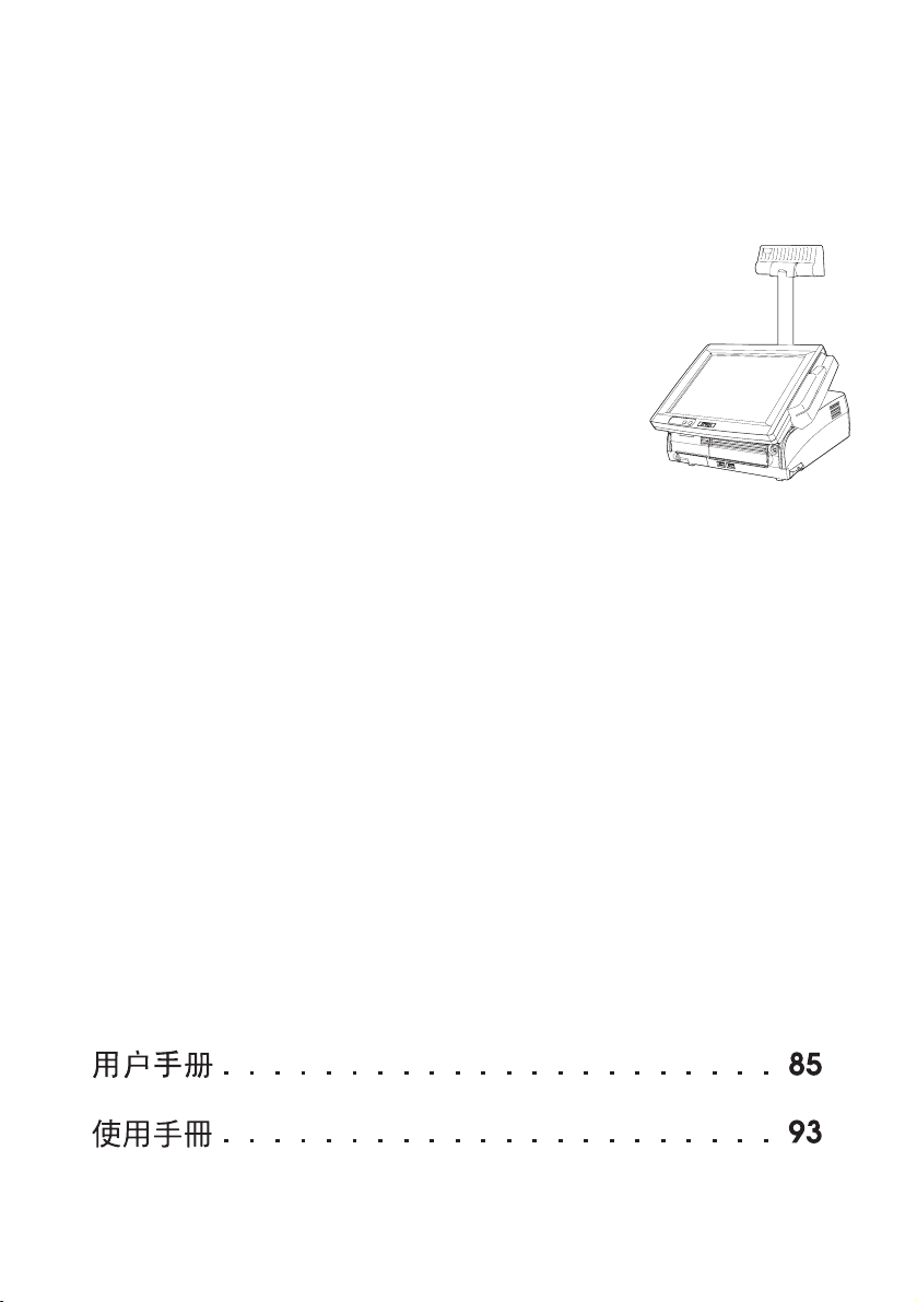
SR-610
User’s Manual. . . . . . . . . . . . . . . . . . . . 1
Benutzerhandbuch . . . . . . . . . . . . . . . . 11
Gebruikershandleiding . . . . . . . . . . . . . 23
Manuel de l’utilisateur . . . . . . . . . . . . . . 33
Manual do utilizador . . . . . . . . . . . . . . . 43
Manual del usuario. . . . . . . . . . . . . . . . 53
Manuale dell’utente . . . . . . . . . . . . . . . 63
Руководство по эксплуатации . . . . . . . . 73
410392502
Page 2
English
A
1
2
10
9
8
3
7
6
15
14
11
12
13
4
5
ii
Page 3
English
B
17
16
22
21
20
18
19
iii
Page 4
English
C
(Bottom)
33
32
31
30
23
24
25
26
27
28
29
iv
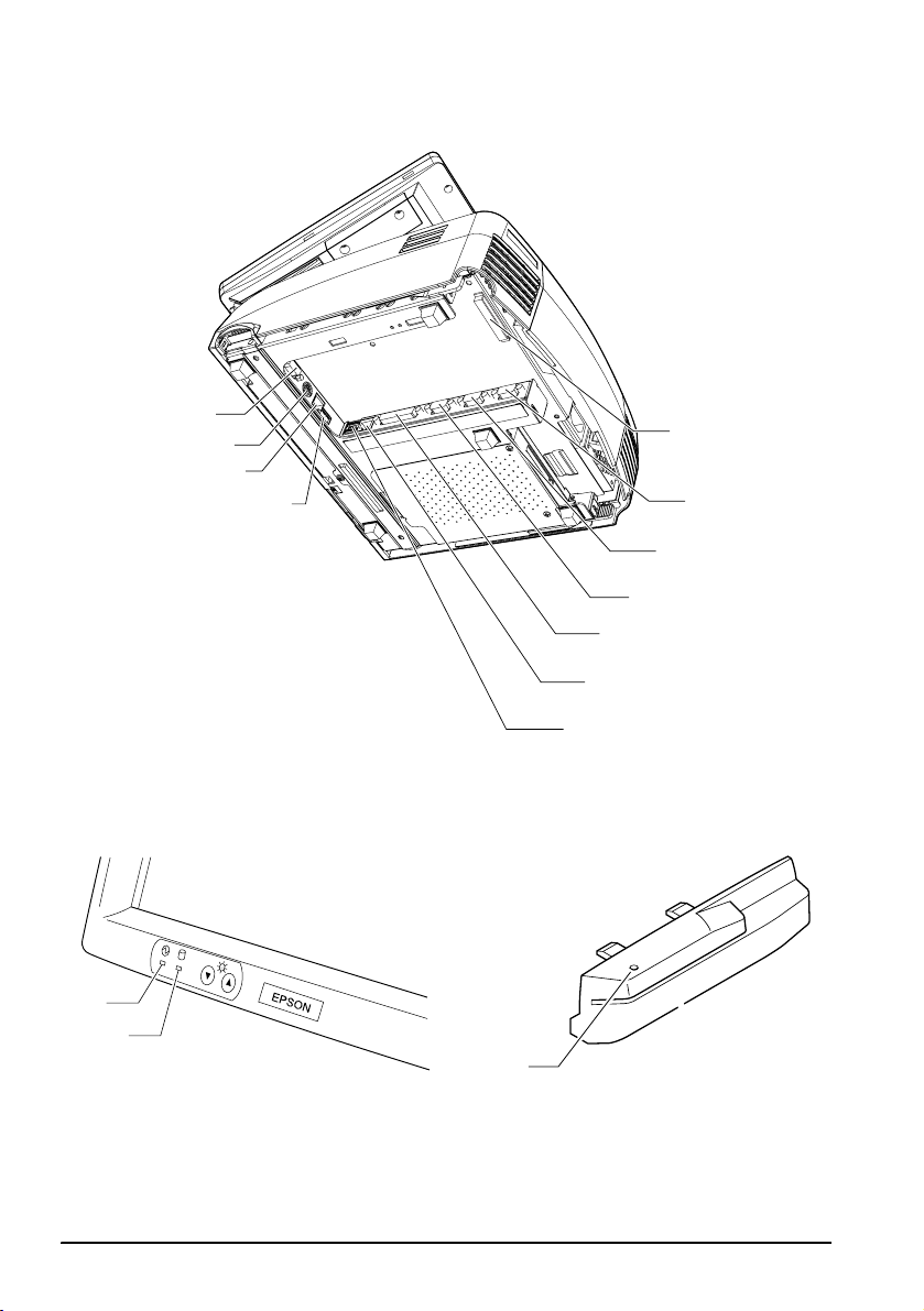
D
LED
34
35
36
Page 5
English
E
F
G
37
v
Page 6
English
H
I
38
vi
J
Page 7
English
K
L
M
39
vii
Page 8

English
N
O
MA2
S
Z
X
MA1
PRG
REG
OFF
40
viii
Page 9
P
Q
English
41
42
R
S
2
1
ix
Page 10
English
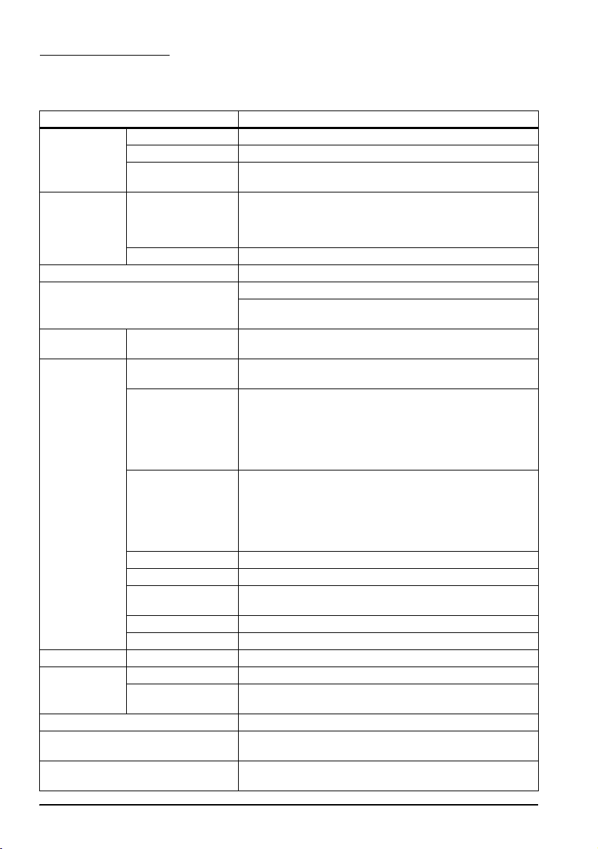
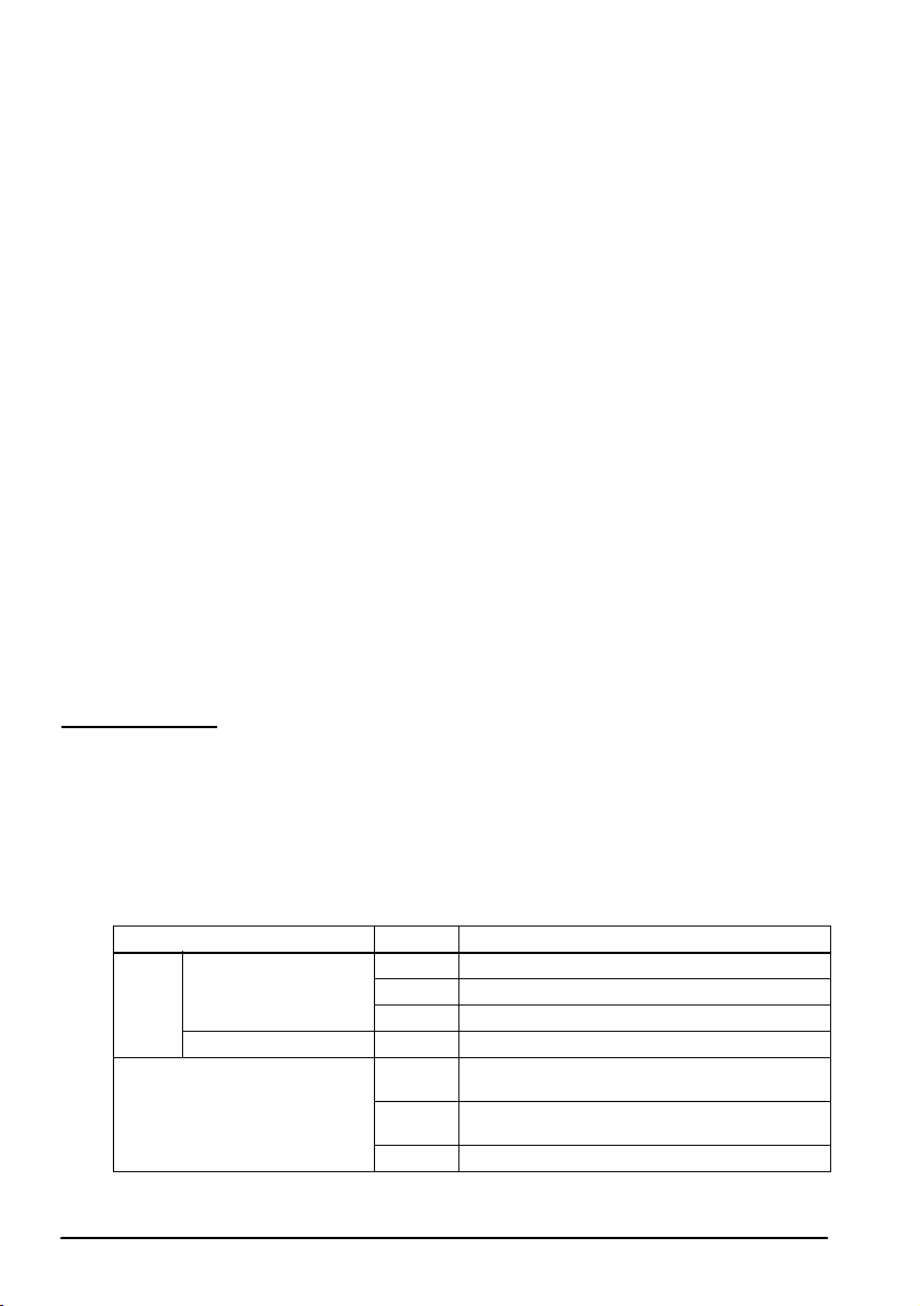
Specifications
SR-610
Item Specification
CPU CPU Intel® Celeron®M 1.3 GHz
Socket mPGA479M socket
Secondary cache
memory
Memory Main memory 184 pin DDR SDRAM DIMM slot × 2, Max. 1 GB
BIOS ROM 8 MBit
Chip set Intel 855GME/ICH4 chip set
Video controller Built-in chip set (Supports dual display.)
Sub storage HDD Serial ATA interface with 1 or 2 built in-type 2.5” HDD.
Interface Ethernet (*1) 10 BASE-T / 100 BASE-TX is included as standard.
Shared board for
keyboard/mouse
Serial (*2) × 3 (D-sub male 9-pin)
Parallel × 1 (D-sub female 25-pin) Supports EPP/ECP.
Display (*3) × 1 (D-sub female 15-pin)
USB (*4) External: USB 2.0 × 4 (high/full/low speed support)
Customer display × 1 (RJ-45)
Drawer (DK) × 1
Expansion slot PCI slot (*5) × 1 (DC 3.3 V power supply is provided.) (Revision 2.2)
Sound Beep Can be output to built-in speaker.
Speaker Built-in monaural speaker (with hardware volume
BIOS Supports ACPI 2.0/APM 1.2/Plug & Play/DMI.
Supported OS Windows 2000 Professional SP4 or later
RTC/CMOS backup battery A lithium non-rechargeable battery supplies the backup
512 KB (Built in the CPU.)
(Supports up to DDR DIMM PC2700.)
Note: Operates as PC2700 when using a DIMM of PC2700
or faster.
12.1” LCD, 800 × 600 dots
256K colors (16770K colors can be set.)
RAID-ready for 2 built-in-type (mirroring only)
Wake On LAN available
× 2 PS/2-compliant (6-pin mini-DIN)
Either the front connector or the bottom connector is
available.
Can be switched with the DIP switch.
Both keyboard and mouse can be connected using
branch cable.
Can be set in the BIOS settings so that it outputs DC5 V to
pin 1 through COM1 and COM2.
COM3 can be set in the BIOS settings to be used as
Normal, TM/DM-D, DRW, DM-D port. (*6)
Supports Wake up function (Modem Ring On) of pin 9 (RI).
Internal: × 1 (For optional CompactFlash Board)
control)
Windows XP Professional SP2 or later
voltage to the RTC.
x
Page 11
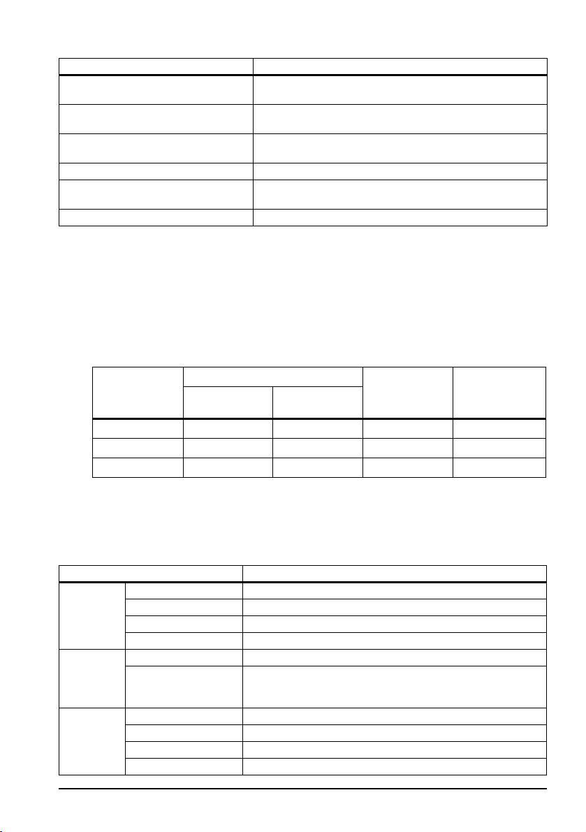
Item Specification
Power supply AC 100 V ~ 240 V/50 Hz ~ 60 Hz
Max. 5.0 A
Temperature Operation: 5 ° C ~ 35 ° C
Storage: -10 ° C ~ 50 °C
Humidity Operation: 30 %RH ~ 80 %RH (No condensation)
Storage: 30 %RH ~ 90 %RH (No condensation)
Case color Epson cool white (ECW)/Epson dark gray (EDG)
Overall dimensions 310 mm (W) × 363 mm (D) × 277 mm (H)
(Rear cover included, LCD unit excluded)
Mass Approx. 8.7 kg (LCD unit and 2 HDDs included)
*1. Ethernet controller/sound controller are included in the standard package, and are
separable in the BIOS settings.
*2. The SR-610 has 4 external ports. However, the customer display uses 1 port, leaving 3 ports
available for external interfaces.
*3. Contents can be displayed separately on the display and LCD using the dual display
function.
*4. Apart from the 4 external ports, one more port is provided for the optional CompactFlash
Board.
*5. PCI slot cannot be used when the optional CompactFlash
*6. COM3 can be set in the BIOS as shown in the table below.
Adapter is attached.
English
BIOS setting COM3 port Customer
Versatile
TM printer
display DM-D
Cash drawer
device
Normal Y(*6) Y N N
TM/DM-D N Y (*7) Y N
DRW/DM-D N N Y Y
Y: Settable N: Not settable
*6: Can be used in the same manner as COM1 and COM2. (However, +5 V cannot be output to
pin 1 [DCD terminal].)
*7: As COM3 becomes the exclusive port for the TM printer, it cannot be used for other devices.
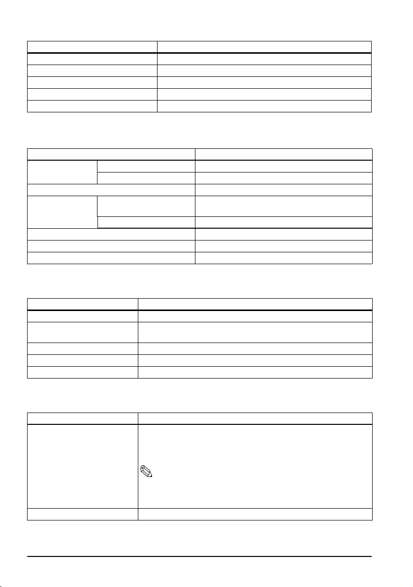
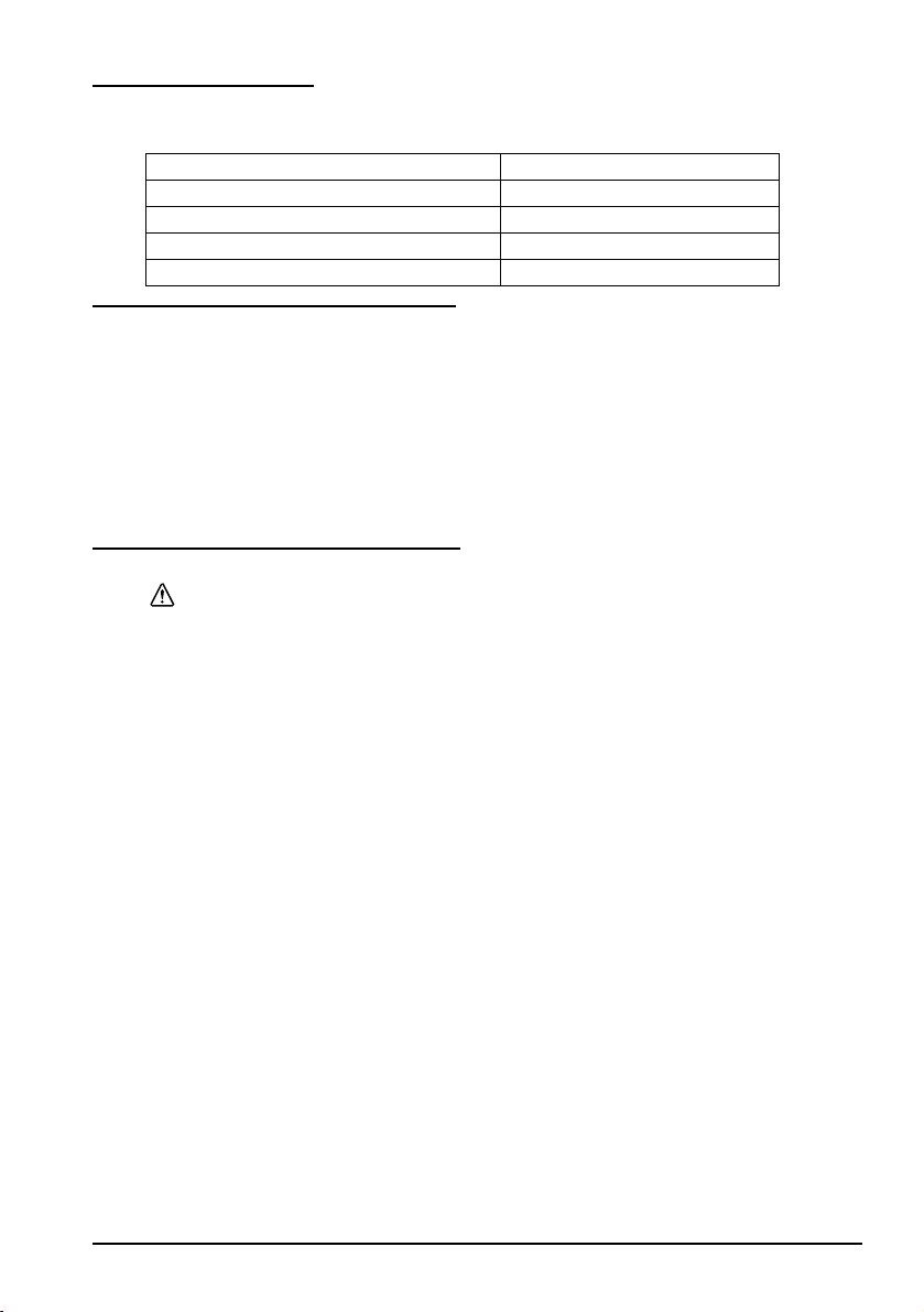
LCD
Item Specification
LCD Size Type 12.1"
Type Color TFT
Resolution 800 × 600 dots
Display color 256K (Approx. 260K)
Backlight Number of backlights 2 lights
Touch
panel
Brightness 272 cd/m2 typ. (Touch panel included)
Method Resistive film (Data can be entered using the touch panel.)
Surface solidity 3H or more (JIS K-5600, ISO/DIS 15184)
Positioning accuracy ± 5 mm maximum
Fingerprint resistance Supported
Brightness is adjustable with the backlight brightness
buttons.
DRW
xi
Page 12
English
Item Specification
MSR interface For connecting DM-MS123
LCD Power LED, HDD LED
Power supply DC +3.3 V, +5 V, +12 V (Supplied by the SR-610.)
Overall dimensions 310 mm (W) × 251.5 mm (D) × 52 mm (H)
Mass Approx. 2.3 kg
60 POS Keyboard DM-KX060
Item Specification
Key switch Alignment 6 × 10
Number of keys 60
Keylock 8 positions
Interface Connector for connecting
to the main unit
USB downstream × 2 USB 1.1 compliant
Overall dimensions 250 mm (W) × 140 mm (D) × 52 mm (H)
Cable length 550 mm
Mass Approx. 800 g
USB 1.1 compliant Type A connector
MSR Unit DM-MS123
Item Specification
Supported card ISO 7811/JIS X6301 Type I, track 1, 2, 3
Connection Can be connected to the side of the LCD unit with a dedicated
Power supply DC 5 V (Supplied from the SR-610.)
Overall dimensions 46 mm (W) × 174 mm (D) × 56 mm (H)
Mass Approx. 270 g
connector.
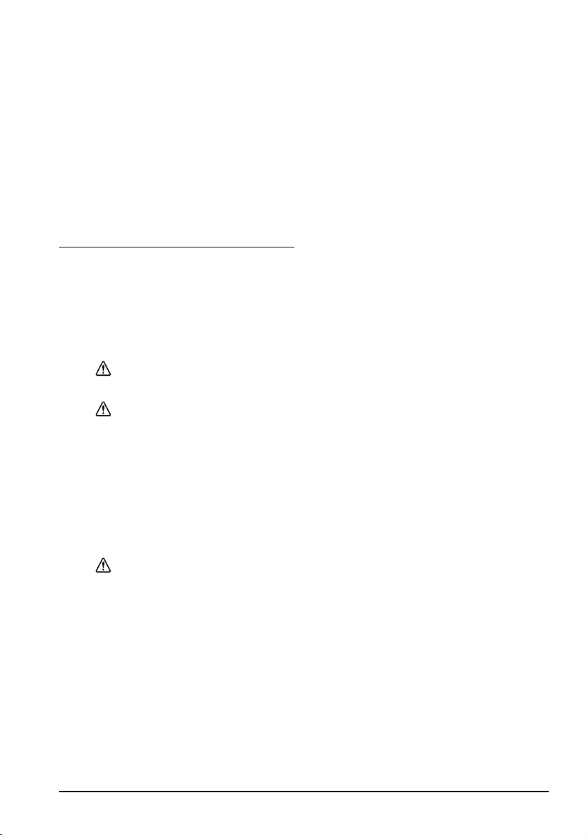
CompactFlash®Adapter OI-S05
Item Specification
Usable cards CompactFlash Storage Card
Mass Approx. 75 g
xii
Type I (3.3mmthick)/Type II (5mmthick)
CF+ Card
Type I (3.3mm thick) or Type II (5mm thick)
Note:
CF+ Card I/O cards (modem, LAN, etc.) or longer or extended
cards (cards that exceed 36.55mm in total length) are not
supported.
Page 13

English
English
SR-610
User’s Manual
Specifications
The technical specifications are at the beginning of this manual.
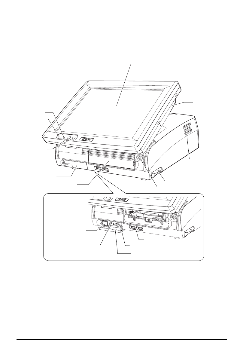
Illustrations
All of the illustrations are at the beginning of this manual. They are identified by letters (A, B, C . . .). Some
of the illustrations have numbers in them. See the list below for the meaning of the numbers. The text has
references to the letters and the numbers. For example: “See Illustration A” or “See A 16.” (“A 16” means
number 16 on Illustration A.)
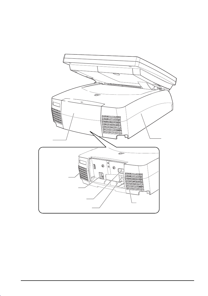
Illustration A: Illustration B: Illustration D:
1. LCD unit 16. Unit cover 34. Power LED
2. MSR cover 17. Rear cover 35. HDD LED
3. Ventilator 18. Power fan 36. LED
4. LCD lever 19. AC inlet Illustration G:
5. Case lock key 20. Main power switch 37. Front power switch
6. Front cover 21. Customer display connector Illustration H:
7. Switch cover 22. Case fan 38. Reset switch
8. LCD backlight brightness
button
9. Power LED 24. COM1
10.HDD LED 25. COM2 Illustration O:
11.USB 26. COM3 40. 8 positions
12.Keyboard/Mouse (Front) 27. LPT Illustration P:
13.Speaker volume control
knob
14.Reset switch 30. DIP switch 42. Eject button
15.Front power switch 31. Drawer connector
All rights reserved. No part of this publication may be reproduced, stored in a retrieval system, or
transmitted in any form or by any means, electronic, mechanical, photocopying, recording, or otherwise,
without the prior written permission of Seiko Epson Corporation. No patent liability is assumed with
respect to the use of the information contained herein. While every precaution has been taken in the
preparation of this book, Seiko Epson Corporation assumes no responsibility for errors or omissions.
Neither is any liability assumed for damages resulting from the use of the information contained herein.
Neither Seiko Epson Corporation nor its affiliates shall be liable to the purchaser of this product or third
parties for damages, losses, costs, or expenses incurred by purchaser or third parties as a result of:
accident, misuse, or abuse of this product or unauthorized modifications, repairs, or alterations to this
product, or (excluding the U.S.) failure to strictly comply with Seiko Epson Corporation’s operating and
maintenance instructions.
Illustration C: (Bottom) Illustration L:
23. Cable clamp 39. Backlight brightness
button
28. Ethernet 41. CompactFlash card
29. USB Illustration Q:
32. Keyboard/Mouse (Bottom)
33. Display
SR-610 User’s Manual 1
Page 14

English
Seiko Epson Corporation shall not be liable against any damages or problems arising from the use of any
options or any consumable products other than those designated as Original Epson Products or Epson
Approved Products by Seiko Epson Corporation.
Epson® and ESC/POS® are registered trademarks of Seiko Epson Corporation.
Intel®, Celeron® and Pentium® are trademarks or registered marks of Intel Corporation.
MS-DOS®, Microsoft®, Windows® and WindowsNT® are trademarks or registered trademarks of
Microsoft Corporation in the United States and/or other countries.
CompactFlash® is a trademark of SanDisk Corporation, registered in the United States and other countries.
IBM®, PC/AT®, PS/2® are trademarks or resistered trademarks of International Business Machines
Corporation in the United States, other countries, or both.
NOTICES:
Other product and company names used herein are for identification purposes only and may be
trademarks or registered trademarks of their respective companies. Epson disclaims any and all rights in
those marks.
The contents of this manual are subject to change without notice.
Copyright © 2005 by Seiko Epson Corporation, Nagano, Japan.
EMC and Safety Standards Applied
Product Name: IM-610, DM-LS121T
Model Name: M164B, M169B
The following standards are applied only to the units that are so labeled.
Europe: CE Marking
North America: EMI: FCC/ICES-003 Class A
Japan: EMI: VCCI Class A
Oceania: EMC: AS/NZS CISPR22 Class A
The connection of a non-shielded printer interface cable to this device will invalidate the EMC standards
of this device.
You are cautioned that changes or modifications not expressly approved by Seiko Epson Corporation
could void your authority to operate the equipment.
CE Marking
The unit conforms to the following Directives and Norms:
Directive 89/336/EEC EN 55022 Class A
Directive 73/23/EEC Safety: EN 60950
This is a Class A product. In a domestic environment this product may cause radio interference in which
case the user may be required to take adequate measures.
Safety: UL 60950/ CSA C22.2
No. 60950
JIS C 61000-3-2
WARNING
EN 55024
IEC 61000-4-2
IEC 61000-4-3
IEC 61000-4-4
IEC 61000-4-5
IEC 61000-4-6
IEC 61000-4-11
EN 61000-3-2
EN 61000-3-3
WARNING
CAUTION:
Connecting an outdoor overhead LAN cable directly to your product may lead to lightning
damage. If you need to connect such a cable to your product, the cable must be protected
against an electrical surge between the cable and your product. You should avoid connecting
your product to a non-surge protected outdoor overhead LAN cable.
2 SR-610 User’s Manual
Page 15
English
FCC Compliance Statement For American Users
This equipment has been tested and found to comply with the limits for a Class A digital device, pursuant
to Part 15 of the FCC Rules. These limits are designed to provide reasonable protection against harmful
interference when the equipment is operated in a commercial environment.
This equipment generates, uses, and can radiate radio frequency energy and, if not installed and used in
accordance with the instruction manual, may cause harmful interference to radio communications.
Operation of this equipment in a residential area is likely to cause harmful interference, in which case the
user will be required to correct the interference at his own expense.
For Canadian Users
This Class A digital apparatus complies with Canadian ICES-003.
Disposal or Recycling
This product includes a lamp component that contains mercury (Hg). Please consult your state and local
regulations regarding disposal or recycling. Do not put it in the trash.
Important Safety Information
This section presents important information intended to ensure safe and effective
use of this product. Read this section carefully and store it in an accessible location.
Key to Symbols
The symbols in this manual are identified by their level of importance, as defined
below. Read the following carefully before handling the product.
WARNING:
Warnings must be observed carefully to avoid serious bodily injury.
CAUTION:
Cautions must be observed to avoid minor injury to yourself, damage to your
equipment, or loss of data.
Note:
Notes have important information and useful tips on the operation of your product.
Safety Precautions
This section describes the warnings and cautions intended to ensure safe and
effective use of the SR-610. Other warnings and cautions on handling of this
product for its safe and effective use are described in individual sections.
WARNINGS:
Turn off the main power switch of the SR-610 immediately and unplug the power
cable if the SR-610 produces smoke, a strange odor, or unusual noise. Continued
use may lead to fire or electric shock. Contact your dealer or an Epson service
center for advice.
Never attempt to repair this product yourself. Improper repair work can be
dangerous.
Never disassemble or modify this product. Tampering with this product may
result in injury, fire, or electric shock.
Never insert or disconnect the power plug with wet hands. Doing so may result
in severe shock.
Do not allow foreign objects to fall into this product. Penetration by foreign
objects may lead to fire or shock.
SR-610 User’s Manual 3
Page 16

English
If water or other liquid spills into this product, turn off the main power switch of
the SR-610, unplug the power cable of the SR-610 immediately, and then
contact your dealer or an Epson service center for advice. Continued use may
lead to fire or shock.
Always supply power directly from a standard domestic power outlet.
Do not place multiple loads on the power outlet (wall outlet). Overloading the
outlet may lead to fire.
The equipment must be installed near the power outlet, and the outlet must be
easily accessible in case of emergency.
Be sure your power cable meets the relevant safety standards and includes a
power system ground terminal (PE terminal).
Handle the power cable with care. Improper handling of the power cable may
cause fire or electric shock.
• Do not modify or attempt to repair the cable.
• Do not place any heavy object on top of the cable.
• Avoid excessive bending, twisting, and pulling of the cable.
• Do not place the cable near heating equipment.
• Check that the plug is clean before plugging it in.
• Be sure to push the prongs all the way in.
• Do not use a damaged cable.
Regularly remove the power plug from the outlet and clean the base of the
prongs and between the prongs. If you leave the power plug in the outlet for a
long time, dust may collect on the base of the prongs, causing a short and fire.
Do not block the openings of this product. The product overheats and fire may
result.
• Do not place the product in an unventilated narrow location, such as
a bookshelf.
• Do not place the product on carpet or bedding.
• Do not cover the product with a blanket or tablecloth.
Do not connect a telephone line to the drawer-kick connector of the printer.
The telephone line or printer may become damaged.
Do not disassemble, charge, deform, or leave the internal lithium battery in a
hot place such as near a fire or on a heater. This could result in explosion or
release of hazardous chemicals, leading to injury.
There is a danger of explosion if the battery is incorrectly replaced. Replace
only with the same or equivalent type recommended by the manufacturer.
Dispose of used batteries according to the manufacturer's instructions.
CAUTIONS:
If you power off the SR-610, wait more than 10 seconds before you power it on
again. If the SR-610 is powered on without an interval, it may not start up
normally.
Do not connect the unit to power outlets that are close to devices that
generate voltage fluctuations or electrical noise. In particular, stay clear of
devices that use large electric motors. Otherwise, the SR-610 and the POS
system may malfunction.
Do not use this product with any voltage other than the specified one. Doing so
may lead to fire.
Always connect the power cable to the AC inlet of this product before
plugging it into the power outlet.
4 SR-610 User’s Manual
Page 17

English
Be sure to push the plug of the power cable all the way into the AC inlet of this
product.
Always unplug the power cable from the power outlet before unplugging it
from the AC inlet of this product.
When disconnecting the power cable, hold the plug firmly. Do not tug on the
cable itself.
Do not connect the cables in ways other than those specified in this manual.
Different connections may cause equipment damage or fire.
Make sure that the total power requirements of all devices receiving power
from this product do not exceed the power limitation. Otherwise, the product
may become damaged.
Be sure to use this product with the rear cover attached. If it is not attached,
foreign objects may enter this product, causing fire or equipment damage.
Do not use the unit in locations subject to high humidity or dust levels. Excessive
humidity and dust may cause paper jams and other problems, such as fire, or
electric shock.
Be careful when transporting, opening, and incinerating the package. You
may cut your finger on the edge of the cardboard.
Never hold this product by the rear cover, the LCD, the POS keyboard, or the
MSR. The product may break and fall onto the floor, causing possible injury.
Be sure to set this product on a firm, stable, horizontal surface. The product may
break or cause injury if it falls.
Never clean the product with alcohol, benzine, thinner, or other such solvent.
Doing so may damage or break parts made of plastic or rubber.
To ensure safety, unplug this product before leaving it for an extended period.
Do not stand on or place heavy objects on top of this product. Equipment may
fall or collapse, causing breakage and possible injury.
Do not drop, bump, or otherwise subject this product to strong vibration or
impact. The glass of the LCD may break and cause possible injury, or the
product may become damaged.
Do not place anything on the LCD screen and do not let anything contact it.
Doing so may leave a trace on the screen.
Do not attempt to adjust the angle of the LCD with the front key inserted in the
front cover lock. Doing so may break the front cover lock.
Do not use excessive force to rotate the customer display or to change the
angle of it. Doing so may break the customer display or the support.
Do not use magnetic stripe cards that are chipped, cracked, dirty, wet, or have
foreign matter stuck to them. Doing so may break the MSR or damage its
mechanical functions.
Do not use aerosol sprayers containing flammable gas inside or around this
product. Doing so may cause fire.
If you use a LAN cable, be sure to use a shielded one.
Notes:
Be sure to use Epson supplied DIMMs, HDDs, and CPUs.
Be sure to use PCI boards for which Epson has verified the operation. Contact your dealer
for the list of PCI boards whose operation is verified. If you use other PCI boards, carry out
a thorough verification on your own responsibility before use.
To install commercially available applications, consult your dealer.
SR-610 User’s Manual 5
Page 18
English
Part Names
See Illustrations A through O.
LED
The LCD unit has 2 LEDs and the MSR has 1 LED. See Illustration D.
Each LED indicates the following:
LED Color Meaning
LCD Power (D33) Green Power is on (normal).
Orange Stand-by (waiting) mode
Off Power is off.
HDD (D34) Green Accessing the HDD.
MSR (D35)GreenReading was performed correctly.
Orange A read error has occurred.
Off Ready for reading, or power is off.
(The MSR beeps once.)
(The MSR beeps 3 times.)
Peripheral Devices
The following peripheral devices are available for the SR-610.
Hardware Model number
60 POS Keyboard Unit DM-KX060
MSR unit DM-MS123
Customer display DM-D110, DM-D210, DM-D500
CF board OI-S05
Before You Use the Unit
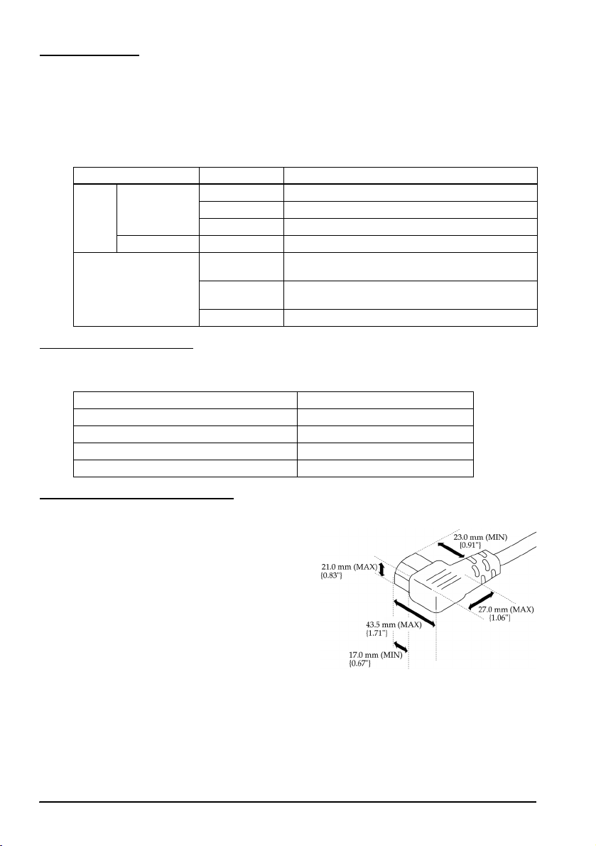
Power Cable
Always use a power cable that meets the
size requirements shown.
6 SR-610 User’s Manual
Page 19
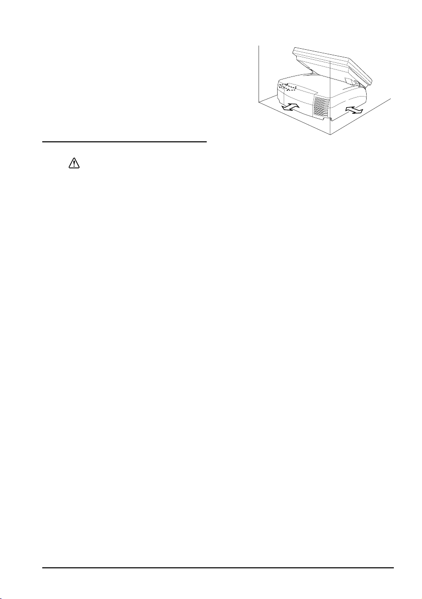
Required Clearance
Secure the installation space, and set up on
a horizontal area which is wider than the
product. Leave a space of 5 cm (2 inches) or
more from the wall when setting it up near
a wall.
Powering On/Off the SR-610
CAUTION:
Continuous operation cannot be recommended because it shortens the life of
the product. When you must operate it continuously, stop the turning of the
hard disk motor during the idle time by referring to the SR-610 Technical
Reference Guide.
Main Power Switch
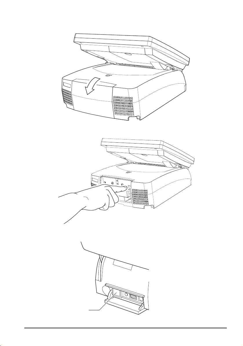
When using this product for the first time, turn on the main power switch. The
main power switch is located under the rear cover. (See B 20.)
1. Pull the lower part of the rear cover as shown in Illustration E and remove it.
2. Turn on the main power switch.
The “O“ engraved on the case means Power OFF, and “|” means Power ON.
The main power switch should usually be kept on. Turn off the unit’s main
power switch only when attaching peripherals, before transporting it, when it
will not be used for an extended period of time. See Illustration F.
3. Attach the rear cover, reversing order of the steps for removal.
English
Front Power Switch
Open the switch cover and press the front power switch to turn it on.
To turn it off, press the front power switch while the SR-610 is in operation. See
Illustration G.
You can also power on the SR-610 through the network.
The operation system of the SR-610 has a standby mode. The system can be set so
that the standby mode can be turned on and off with the front power switch.
If you power off the unit, wait more than 10 seconds before you power it on again.
Note:
Assign the functions to the front power switch through the operating system or BIOS.
Be sure that the power switch of the customer display is always set to on.
Forced Termination
If you cannot power off the SR-610 using applications or the operation system,
you can execute forced termination as a last resort. Keep pressing the front power
switch for approximately 4 seconds until the SR-610 is powered off. Be careful;
when forced termination is executed, all unsaved data is lost.
SR-610 User’s Manual 7
Page 20
English
Reset
Reset restarts the computer while its power is on.
CAUTION:
Do not press the reset switch unless an operating system runaway occurs.
When the system is reset, all unsaved data is lost.
Follow the steps below to reset the computer.
1. Open the switch cover.
2. Press the reset switch (shown in Illustration H) with a pointed object such as a
pen.
Controlling the Speaker Volume
You can control the speaker volume with the speaker volume control.
1. Open the switch cover.
2. Turn the volume control to the left to turn the volume down. Turn it to the
right to turn the volume up. See Illustration I.
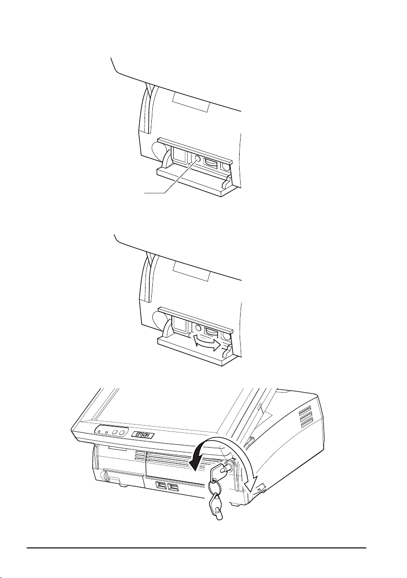
Front Cover Lock
The front cover lock locks both the front cover and the unit cover.
Locking the front cover protects the HDD and other internal parts from theft.
Insert the key into the lock and turn it while slightly pushing it in to lock. Turning
to the right locks and turning to the left unlocks the lock. See Illustration J.
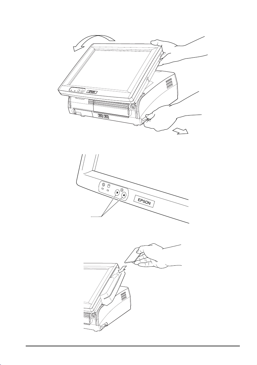
Adjusting the LCD Unit Angle
You can adjust the angle of the LCD unit as you like.
1. Adjust the angle of the LCD unit while pulling the LCD lever on the right side
of the LCD unit. See Illustration K.
2. Release the LCD lock lever to fix the angle. The LCD unit clicks when it is
locked in place.
3. Move the LCD unit slightly up and down to ensure that the LCD unit is
firmly fixed.
Adjusting the LCD Brightness
You can adjust the LCD brightness by pressing the backlight brightness buttons (see
Illustration L). Press the ▼ button to darken the backlight. Press the ▲ button to
brighten the backlight. The new setting is saved even if you power off the SR-610.
Reading Magnetic Stripe Cards
If the MSR unit is installed, you can read magnetic stripe cards.
You can read the data in a magnetic stripe card by swiping the card through the
MSR unit as shown in Illustration M. Hold the card, check the direction of the
arrow printed on the card, and swipe it through the MSR unit.
8 SR-610 User’s Manual
Page 21
Operating the Customer Display
Be sure that the power switch of the customer display is always on. (See B 20.)
Adjusting the Direction
You can change the direction and angle of the display of the customer display by
moving it slowly as you hold down the pole. Adjust the customer display to a
position easy for customers to view. See Illustration N.
CAUTION:
Do not rotate the customer display with excessive force. Doing so may break it.
The mobile range of the display is as follows.
❏ Display rotation: Maximum angle of 90° (45° each to left and right.)
Display tilt
❏ Maximum angle of 48° (4 levels, 5 positions)
Operating the Key Lock key - 60 POS Keyboard Unit
A set of Key Lock keys is provided for the 60 POS keyboard. When the key position
is on OFF, no data can be entered. Each key can be given a different access range to
prevent use of higher functions by unauthorized users. See Illustration O.
Note:
Use application software to set up the Key Lock key.
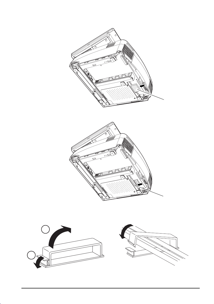
Inserting and Removing CompactFlash Cards
When connecting a CompactFlash adapter, confirm that [Boot Setting
Configuration] - [Onboard Compact Flash] for the BIOS is Disabled. If it is
Enabled the system does not start.
English
CAUTION:
Turn the power switch off before inserting or removing a CompactFlash card.
Do not insert or remove the card when power is on or when the device is in
sleep/standby mode.
Follow the procedure below to insert a CompactFlash card.
1. Slightly lift the back side of the SR-610.
2. Make sure the compactFlash card surface is facing up and press it into the
CompactFlash adapter until you hear a click. See Illustration P.
Follow the procedure below to remove the CompactFlash card.
1. Slightly lift the back side of the SR-610.
2. Press the eject button. See Illustration Q.
The CompactFlash card will be ejected forward. Grasp and remove.
SR-610 User’s Manual 9
Page 22
English
Attaching Peripheral Devices
To attach a peripheral device, connect the device to the connector at the bottom of
the SR-610 and clamp the cables of the device with the cable clamp.
1. Open the cable clamp. See Illustration R.
2. Set the cables inside the cable clamp.
3. Close the cable clamp. See Illustration S.
Keyboard/Mouse
The SR-610 has 2 connectors for the keyboard and mouse; one is inside the front
switch cover, and another is at the bottom of the front switch cover. However,
only one of them can be used at a time.
Use the DIP switch at the bottom of the SR-610 to switch the connectors.
DIP switch - 5 Connector location
OFF Front
ON Bottom
Maintenance
Cleaning
CAUTION:
Never clean the product with alcohol, benzine, thinner, or other such solvents.
Doing so may damage or break the parts made of plastic and rubber.
Display
Wipe away the dirt with a cloth that is dry or slightly moistened with ethanol or
isopropyl alcohol.
Keyboard
Remove dust with a vacuum cleaner.
SR-610
Remove dust around the openings with a vacuum cleaner.
10 SR-610 User’s Manual
Page 23

English
Deutsch
SR-610
Benutzerhandbuch
Technische Daten
Die technischen Daten befinden sich am Anfang dieses Handbuchs.
Abbildungen
Alle Abbildungen befinden sich am Anfang dieses Handbuchs. Sie sind durch Buchstaben
gekennzeichnet (A, B, C…). Einige Abbildungen enthalten Ziffern. Die Bedeutung der Ziffern entnehmen
Sie bitte der folgenden Liste. Der Text enthält Verweise auf Buchstaben und Ziffern. Beispiel: „Siehe
Abbildung A” oder „Siehe A 16”. („A 16” bedeutet Nummer 16 in Abbildung A.)
Abbildung A: Abbildung B: Abbildung D:
1. LCD-Einheit 16. Gehäuseabdeckung 34. Netz-LED
2. Magnetkartenleserge-
häuse
3. Ventilator 19. Netzsteckdose Abbildung G:
4. LCD-Hebel 20. Hauptschalter 37. Front-Ein-/Ausschalter
5. Gehäusesperrschlüssel 21. Anschluss für Kundenanzeige Abbildung H:
6. Frontgehäuse 22. Gehäuseventilator 38. Rücksetztaste
7. Schalterabdeckung Abbildung C: (unten) Abbildung L:
8. LCD Helligkeit Taste 23. Kabelklemme 39. Helligkeitstaste für
9. Netz-LED 24. COM1
10.Festplatten-LED 25. COM2 Abbildung O:
11.USB 26. COM3 40. 8 Positionen
12.Tastatur/Maus (vorn) 27. LPT Abbildung P:
13.Lautstärkeregler 28. Ethernet 41. CompactFlash-Karte
14.Rücksetztaste 29. USB Abbildung Q:
15.Front-Ein-/Ausschalter 30. DIP-Schalter 42. Ausgabetaste
Alle Rechte vorbehalten. Kein Teil dieses Handbuchs darf in irgendeiner Form (Druck, Fotokopie,
Mikrofilm oder ein anderes Verfahren) ohne die schriftliche Genehmigung der EPSON Deutschland
GmbH reproduziert oder unter Verwendung elektronischer Systeme verarbeitet, vervielfältigt oder
verbreitet werden. Alle enthaltenen Informationen werden ohne Rücksicht auf die Patentlage mitgeteilt.
Dieses Handbuch wurde mit großer Sorgfalt erstellt. Eine Haftung für leicht fahrlässige Fehler, z.B.
Druckfehler, ist jedoch ausgeschlossen. Für etwaige Schäden, die aus der Verwendung der hier
enthaltenen Informationen entstehen, wird nicht gehaftet.
Weder die EPSON Deutschland GmbH noch die Seiko Epson Corporation haften für Schäden infolge von
Fehlgebrauch sowie Reparaturen und Abänderungen, die von dritter, nicht autorisierter Seite
vorgenommen wurden.
17. Rückabdeckung 35. Festplatten-LED
18. Stromventilator 36. LED
Hintergrundbeleuchtung
31. Anschluss für Kassenschublade
32. Tastatur/Maus (unten)
33. Display
SR-610 Benutzerhandbuch 11
Page 24

English
EPSON und angegliederte Firmen haften nicht für Schäden oder Störungen durch Einsatz von Optionen
oder Zubehör, wenn diese nicht original EPSON-Produkte oder von der Seiko Epson Corporation
ausdrücklich als „EPSON Approved Product” zugelassen sind.
EPSON® und ESC/POS® sind eingetragene Marken der Seiko Epson Corporation.
Intel®, Celeron® und Pentium® sind Marken oder eingetragene Marken der Intel Corporation.
MS-DOS®, Microsoft®, Windows® und WindowsNT® sind Marken oder in den USA und/oder anderen
Ländern eingetragene Marken der Microsoft Corporation.
CompactFlash® ist eine Marke der SanDisk Corporation, registriert in den Vereinigten Staaten und
anderen Ländern.
IBM®, PC/AT®, PS/2® sind Marken oder in den USA und/oder anderen Ländern eingetragene Marken
der International Business Machines Corporation.
HINWEISE:
Andere im Handbuch genannte Produkt- und Firmennamen dienen lediglich Identifikationszwecken und
sind möglicherweise Marken oder eingetragene Marken der jeweiligen Eigentümer. EPSON erhebt
keinerlei Ansprüche auf diese Marken.
Der Inhalt dieses Handbuchs kann ohne vorherige Ankündigung jederzeit geändert werden.
Copyright © 2005, Seiko Epson Corporation, Nagano, Japan.
Angewandte EMV- und Sicherheitsnormen
Produktname: IM-610, DM-LS121T
Modellname: M164B, M169B
Die folgenden Normen gelten nur für entsprechend gekennzeichnete Einheiten.
Europa: CE-Zeichen
Nordamerika: EMI: FCC/ICES-003 Klasse A
Japan: EMI: VCCI Klasse A
Ozeanien: EMV: AS/NZS CISPR22 Klasse A
Wird dieses Gerät über ein nicht abgeschirmtes Druckerschnittstellenkabel angeschlossen, ist die
Einhaltung der EMV-Vorschriften durch das Gerät nicht mehr gegeben.
Durch Änderungen oder Modifikationen, die nicht ausdrücklich von der Seiko Epson Corporation
genehmigt wurden, wird Ihre Berechtigung zum Betrieb des Geräts möglicherweise ungültig.
CE-Zeichen
Das Gerät erfüllt folgende Richtlinien und Normen:
Richtlinie 89/336/EWG EN 55022 Klasse A
Richtlinie 73/23/EWG Sicherheit: EN 60950
Dies ist ein Gerät der Klasse A. In Wohnbereichen kann dieses Produkt Rundfunkstörungen verursachen;
in diesem Fall muss der Benutzer geeignete Abhilfemaßnahmen treffen.
Sicherheit: UL 60950/ CSA C22.2
Nr. 60950
JIS C 61000-3-2
WARNUNG
EN 55024
IEC 61000-4-2
IEC 61000-4-3
IEC 61000-4-4
IEC 61000-4-5
IEC 61000-4-6
IEC 61000-4-11
EN 61000-3-2
EN 61000-3-3
WARNUNG
12 SR-610 Benutzerhandbuch
Page 25
English
VORSICHT:
Wird ein im Freien aufgehängtes LAN-Kabel direkt an das Gerät angeschlossen, kann das Gerät
durch Blitzschlag beschädigt werden. Muss ein solches Kabel an das Gerät angeschlossen
werden, so muss zwischen dem Kabel und dem Gerät eine Schutzvorrichtung für elektrische
Überspannungen installiert werden. Das Gerät darf nicht an ein im Freien aufgehängtes LANKabel angeschlossen werden, das nicht mit einem Überspannungsschutz ausgestattet ist.
GERÄUSCHPEGEL
Gemäß der Dritten Verordnung zum Gerätesicherheitsgesetz
(Maschinenlärminformations- Verordnung-3. GSGV) ist der arbeitsplatzbezogene
Geräusch-Emissionswert kleiner als 70 dB(A) (basierend auf ISO 7779).
Wichtige Sicherheitsinformationen
Dieser Abschnitt enthält wichtige Informationen für den sicheren und effektiven
Einsatz des Geräts. Lesen Sie diesen Abschnitt sorgfältig durch und bewahren Sie
ihn leicht zugänglich auf.
Erklärung der Symbole
Die in diesem Handbuch verwendeten Symbole sind nach Bedeutungsgrad
gegliedert (siehe Definition unten). Lesen Sie folgende Informationen vor der
Handhabung des Geräts sorgfältig durch.
WARNUNG:
Warnungen müssen genau eingehalten werden, um schwere
Körperverletzungen zu vermeiden.
VORSICHT:
Vorsichtshinweise müssen eingehalten werden, um leichte Verletzungen,
Geräteschäden oder Datenverluste zu vermeiden.
Hinweis:
Hinweise enthalten wichtige Informationen und nützliche Tipps zum Betrieb des Geräts.
Sicherheitsvorkehrungen
Dieser Abschnitt enthält Warnungen und Sicherheitshinweise für den sicheren
und effektiven Gebrauch des SR-610. Weitere Warnungen und
Sicherheitshinweise für den sicheren und effektiven Umgang mit diesem Produkt
sind in den jeweiligen Abschnitten zu finden.
WARNUNGEN:
Schalten Sie den SR-610 sofort aus und ziehen Sie das Netzkabel, wenn das Gerät
anfängt zu rauchen bzw. seltsame Gerüche oder Geräusche von sich gibt. Bei
weiterer Verwendung besteht Feuer- und Stromschlaggefahr. Wenden Sie sich
an Ihren Fachhändler oder ein Epson Service Center.
Versuche Sie nie das Gerät selbst zu reparieren. Unsachgemäß durchgeführte
Reparaturen können gefährlich sein.
Nehmen Sie das Gerät nicht auseinander und ändern Sie es auf keinerlei Weise
ab. Unbefugte Arbeiten an diesem Gerät können zu Verletzungen, Brand oder
elektrischem Schlag führen.
Stecken Sie den Netzstecker niemals mit nassen Händen ein oder ziehen ihn
heraus. Anderenfalls besteht die Gefahr eines starken elektrischen Schlages.
SR-610 Benutzerhandbuch 13
Page 26

English
Lassen Sie keine Fremdkörper in dieses Gerät fallen. Fremdkörper können einen
Brand oder elektrischen Schlag verursachen.
Falls Wasser oder sonstige Flüssigkeiten in dieses Gerät eindringen, schalten Sie
sofort den Hauptschalter des SR-610 aus, ziehen Sie den Netzstecker heraus und
setzen Sie sich dann mit Ihrem Händler oder einem Epson Service Center in
Verbindung. Bei weiterer Verwendung besteht Feuer- und Stromschlaggefahr.
Verwenden Sie als Netzspannungsquelle immer eine standardmäßige
Haushaltssteckdose.
Schließen Sie nicht mehrere Lasten an dieselbe Steckdose an. Überlastete
Steckdosen können Brände verursachen.
Das Gerät muss in der Nähe der Steckdose aufgestellt werden und die
Steckdose muss im Notfall leicht zugänglich sein.
Sorgen Sie dafür, dass das Netzkabel den geltenden Sicherheitsvorschriften
entspricht und über einen Schutzkontakt verfügt.
Behandeln Sie das Stromkabel sorgfältig. Bei unsachgemäßer Handhabung des
Netzkabels besteht Feuer- und Stromschlaggefahr.
• Versuchen Sie nicht, das Kabel abzuändern oder zu reparieren.
• Stellen Sie keine schweren Gegenstände auf das Kabel.
• Vermeiden Sie das Kabel übermäßig zu biegen, zu verdrehen oder zu
ziehen.
• Verlegen Sie das Kabel nicht in der Nähe von Heizgeräten oder
anderen Wärmequellen.
• Stellen Sie vor dem Einstecken des Steckers sicher, dass er sauber ist.
• Führen Sie die Pole des Steckers vollständig in die Steckdose ein.
• Verwenden Sie keine beschädigten Kabel.
Nehmen Sie das Netzkabel regelmäßig aus der Steckdose und reinigen Sie die
Basis der Pole und den Bereich zwischen den Polen. Wenn der Stecker über
lange Zeit hinweg in der Steckdose bleibt, kann sich Staub an der Basis der Pole
ansammeln, was einen Kurzschluss und einen Brand verursachen kann.
Blockieren Sie die Öffnungen dieses Geräts nicht. Das Gerät kann sich sonst
überhitzen und einen Brand verursachen.
• Stellen Sie das Gerät nicht an einem schmalen, unbelüfteten Ort auf
(wie beispielsweise einem Bücherregal).
• Stellen Sie das Gerät nicht auf einen Teppich oder auf eine andere
weiche Oberfläche.
• Legen Sie keine Decke oder Tischdecke über das Gerät.
Stecken Sie keine Telefonleitung in den Anschluss für die Kassenschublade des
Druckers. Die Telefonleitung und/oder der Drucker können sonst beschädigt
werden.
Den internen Lithium-Akku von Hitze (z.B. Kaminfeuer und Heizgeräten)
fernhalten und nicht auseinandernehmen oder verformen. Andernfalls besteht
Verletzungsgefahr durch Explosion oder Freigabe gefährlicher Chemikalien.
Es besteht Explosionsgefahr, wenn der Akku falsch ersetzt wird. Ersetzen Sie ihn
nur durch den gleichen oder einen gleichwertigen, vom Hersteller
empfohlenen Typ. Entsorgen Sie verbrauchte Akkus gemäß den Vorschriften
des Herstellers.
14 SR-610 Benutzerhandbuch
Page 27

English
VORSICHT:
Warten Sie nach dem Ausschalten des SR-610 mindestens 10 Sekunden, bevor
Sie es wieder einschalten. Wird diese Frist nicht eingehalten, können Fehler
beim Hochfahren des SR-610 auftreten.
Schließen Sie das Gerät nicht in eine Steckdose an, die sich in der Nähe von
Geräten befindet, die Spannungsschwankungen oder elektrische Störungen
verursachen. Meiden Sie insbesondere Geräte mit großen Elektromotoren.
Anderenfalls kann es zu Betriebsstörungen des SR-610 und des POS-Systems
kommen.
Betreiben Sie das Gerät nur mit der angegebenen Spannung. Anderenfalls
besteht Feuergefahr.
Stecken Sie das Netzkabel immer zuerst in den 220 V Netzanschluss dieses
Gerätes, bevor Sie es in eine Steckdose einstecken.
Schieben Sie den Stecker des Netzkabels immer bis zum Anschlag in den 220 V
Netzanschluss dieses Geräts.
Ziehen Sie das Netzkabel immer zuerst aus der Steckdose, bevor Sie es aus den
220 V Netzanschluss dieses Geräts ziehen.
Halten Sie den Stecker beim Herausziehen des Netzkabels gut fest. Ziehen Sie
immer am Stecker und nicht am eigentlichen Kabel.
Schließen Sie die Kabel nur so an, wie dies im vorliegenden Handbuch
beschrieben wird. Andersartige Kabelverbindungen können Geräteschäden
oder Brände verursachen.
Achten Sie darauf, dass der Gesamtstrombedarf aller Geräte, die von diesem
Produkt mit Strom versorgt werden, die Leistungsgrenze nicht übersteigt.
Andernfalls besteht Gefahr, dass das Produkt beschädigt wird.
Betreiben Sie das Gerät nur mit befestigter Rückabdeckung. Ist die
Rückabdeckung nicht angebracht, können Fremdkörper in das Gerät
gelangen, die ein Feuer verursachen oder das Gerät beschädigen können.
Verwenden Sie das Gerät nicht in Umgebungen mit hoher Luftfeuchtigkeit oder
hohem Staubgehalt. Ein übermäßiger Feuchtigkeits- oder Staubgehalt kann
Papierstaus und andere Störungen verursachen, beispielsweise Feuer oder
elektrische Schläge.
Gehen Sie beim Transportieren, Öffnen und Entsorgen des Verpackungsmaterials
vorsichtig vor. Scharfe Kartonränder können Schnittwunden verursachen.
Halten Sie das Gerät niemals an der Rückabdeckung, der LCD, der POSTastatur oder dem Magnetkartenleser fest. Das Gerät kann sonst brechen und
fallen, was zu Körperverletzungen führen kann.
Stellen Sie das Gerät auf eine feste, stabile und horizontale Arbeitsfläche. Wird
das Gerät fallengelassen, kann es brechen oder Verletzungen verursachen.
Reinigen Sie das Gerät niemals mit Alkohol, Benzol, Verdünnung oder ähnlichen
Lösungsmitteln. Anderenfalls können Kunststoff- oder Gummiteile beschädigt
werden.
Um mögliche Gefahren zu vermeiden, trennen Sie das Gerät vom 220 V-Netz,
wenn Sie es für längere Zeit unbeaufsichtigt lassen.
Stellen Sie Sich nicht auf das Gerät und stellen auch Sie keine schweren
Objekte darauf. Das Gerät kann fallen oder brechen, was zu Schäden und
möglichen Körperverletzungen führen kann.
SR-610 Benutzerhandbuch 15
Page 28
English
Setzen Sie das Gerät keinen Stößen, Schlägen oder starken Vibrationen aus.
Das Glas der LCD-Anzeige kann brechen und Körperverletzungen verursachen
und das Gerät kann beschädigt werden.
Legen Sie nichts auf den LCD-Bildschirm und halten Sie Gegenstände davon
fern. Andernfalls kann der Bildschirm zerkratzt werden.
Versuchen Sie nicht, den Winkel der LCD zu verstellen, während der
Frontschlüssel vorn im Frontgehäuseschloss steckt. Andernfalls kann das
Frontgehäuseschloss beschädigt werden.
Üben Sie beim Drehen der Kundenanzeige oder Einstellen des Winkels keine
übermäßige Kraft aus, um eine Beschädigung der Kundenanzeige oder der
Halterung zu vermeiden.
Verwenden Sie keine Magnetkarten, die feucht sind oder Kerben, Risse,
Verschmutzungen oder anhaftende Fremdkörper aufweisen. Andernfalls kann
der Magnetkartenleser (MSR) beschädigt oder deren mechanische Funktionen
beeinträchtigt werden.
Verwenden Sie keine brennbaren Sprühmittel in und in der Nähe des Gerätes.
Brandgefahr!
Wenn Sie ein LAN-Kabel verwenden, verwenden Sie unbedingt ein
abgeschirmtes Kabel.
Hinweise:
Verwenden Sie ausschließlich DIMMs, Festplatten und Prozessoren von EPSON.
Verwenden Sie PCI-Karten, deren ordungsgemäßer Betrieb von EPSON bestätigt wurde.
Eine Liste der bestätigten PCI-Karten erhalten Sie bei Ihrem Fachhändler. Sollen andere
PCI-Karten verwendet werden, müssen Sie zuvor eine sorgfältige Prüfung auf eigene
Verantwortung durchführen.
Informationen zur Installation gewerblicher Anwendungen erhalten Sie bei Ihrem
Fachhändler.
Teilenamen
Siehe Abbildungen A bis O.
LED
Die LCD-Einheit weist 2 LED-Anzeigen und der Magnetkartenleser 1 LED-Anzeige
auf. Siehe Abbildung D.
Die LEDs haben folgende Bedeutung:
LED Farbe Bedeutung
LCD Betriebsanzeige (D33) grün Gerät ist eingeschaltet (normal)
orange Standby-Modus (Wartezustand)
aus Gerät ist ausgeschaltet
Festplatte (D34) grün Zugriff auf die Festplatte
Magnetkartenleser (D35) grün Der Lesevorgang wurde korrekt ausgeführt.
orange Es ist ein Lesefehler aufgetreten.
aus Lesebereit oder Strom ist ausgeschaltet.
16 SR-610 Benutzerhandbuch
(Der Magnetkartenleser gibt einen Piepton ab.)
(Der Magnetkartenleser gibt 3 Pieptöne ab.)
Page 29
Peripheriegeräte
Für den SR-610 sind folgende Peripheriegeräte erhältlich:
Hardware Modelnummer
POS-Tastatur mit 60 Tasten DM-KX060
Magnetkartenleser DM-MS123
Kundenanzeige DM-D110, DM-D210, DM-D500
CF-Karte OI-S05
Vor Verwendung der Einheit
Netzkabel
Verwenden Sie stets ein Netzkabel, dass den angezeigten
Anschlussvoraussetzungen entspricht. Siehe die Abbildung auf Seite 6.
Erforderlicher Abstand
Legen Sie fest, wo die Einheit aufgestellt werden soll; wählen Sie eine horizontale
Fläche, die breiter ist als das Produkt. Beim Aufstellen vor einer Wand halten Sie
mindestens 5 cm Abstand zur Wand. Siehe die Abbildung auf Seite 7.
Ein-/Ausschalten des SR-610
VORSICHT:
Der kontinuierliche Betrieb kann nicht empfohlen werden, da hierdurch die
Produktlebensdauer verkürzt wird. Wenn das Gerät kontinuierlich betrieben
werden soll, unterbrechen Sie die Festplattenmotorrotationen in den
Pausezeiten gemäß der technischen Referenz (Technical Reference Guide) für
den SR-610.
Hauptschalter
Schalten Sie bei der erstmaligen Verwendung des Produkts den Hauptschalter
ein. Der Hauptschalter befindet sich unter der Rückabdeckung. (Siehe B 20.)
1. Ziehen Sie den unteren Teil der Rückabdeckung wie in Abbildung E gezeigt ab.
2. Schalten Sie den Hauptschalter ein.
Das ins Gehäuse eingravierte „O“ bedeutet „Strom AUS” und „|” bedeutet
„Strom EIN”. Normalerweise sollte der Hauptschalter eingeschaltet bleiben.
Schalten Sie den Hauptschalter der Einheit nur aus, ehe Sie Peripheriegeräte
anschließen oder das Produkt transportieren sowie bei längerer
Nichtverwendung. Siehe Abbildung F.
3. Bringen Sie die Rückabdeckung (in umgekehrter Reihenfolge wie beim
Abnehmen) an.
English
SR-610 Benutzerhandbuch 17
Page 30
English
Front-Ein-/Ausschalter
Öffnen Sie die Schalterabdeckung und drücken Sie den Front-Ein-/Ausschalter
zum Einschalten des Geräts.
Zum Ausschalten drücken Sie den Front-Ein-/Ausschalter, während der SR-610
in Betrieb ist. Siehe Abbildung G.
Sie können den SR-610 auch über das Netzwerk einschalten.
Das Bedienungssystem des SR-610 hat einen Standby-Modus. Das System kann so
eingestellt werden, dass der Standby-Modus mit dem Front-Ein-/Ausschalter einund ausgeschaltet werden kann.
Wenn Sie die Einheit ausschalten, warten Sie länger als 10 Sekunden, ehe Sie die
Einheit wieder einschalten.
Hinweis:
Die Funktionen des Front-Ein-/Ausschalters werden über das Betriebssystem oder BIOS
zugewiesen.
Sorgen Sie dafür, dass der Ein-/Ausschalter der Kundenanzeige immer
eingeschaltet ist.
Zwangsabschaltung
Wenn der SR-610 nicht über die Anwendungen oder das Betriebssystem
heruntergefahren werden kann, können Sie als letztes Mittel eine
Zwangsabschaltung ausführen. Halten Sie den Ein-/Ausschalter ca. 4 Sekunden
lang gedrückt, bis der SR-610 ausgeschaltet ist. Beachten Sie jedoch, dass dabei
sämtliche Daten, die noch nicht gespeichert wurden, verloren gehen.
Rücksetzen (Reset)
Mit der Systemrücksetztaste wird der Computer neu gestartet, während er
eingeschaltet ist.
VORSICHT:
Drücken Sie die Rücksetztaste nur, wenn ein nicht behebbarer Fehler im
Betriebssystem aufgetreten ist. Beim Zurücksetzen des Systems gehen alle noch
nicht gespeicherten Daten verloren.
Gehen Sie beim Zurücksetzen des Computers wie folgt vor:
1. Öffnen Sie die Schalterabdeckung.
2. Drücken Sie die Rücksetztaste (siehe Abbildung H) mit einem spitzen
Gegenstand, wie beispielsweise einem Kugelschreiber.
Einstellen der Lautstärke
Die Lautstärke des Lautsprechers ist einstellbar.
1. Öffnen Sie die Schalterabdeckung.
2. Drehen Sie den Lautstärkeregler zum Leiserdrehen nach links, zum
Lauterdrehen nach rechts. Siehe Abbildung I.
18 SR-610 Benutzerhandbuch
Page 31

Frontgehäuseschloss
Das Frontgehäuseschloss dient zum Abschließen der Frontabdeckung und der
Gehäuseabdeckung.
Durch Absperren des Frontgehäuses können die Festplatte und sonstigen internen
Teile vor Diebstahl geschützt werden.
Stecken Sie den Schlüssel in das Schloss und drehen Sie den Schlüssel, während
Sie ihn leicht in das Schloss hineindrücken. Durch Drehen nach rechts wird das
Schloss zugesperrt, durch Drehen nach links aufgesperrt. Siehe Abbildung J.
Einstellen des Winkels der LCD-Einheit
Sie können den Winkel der LCD-Einheit nach Wunsch einstellen.
1. Stellen Sie den Winkel der LCD-Einheit ein, während Sie am LCD-Hebel an
der rechten Seite der LCD-Einheit ziehen. Siehe Abbildung K.
2. Geben Sie zum Feststellen des Winkels den LCD-Sperrhebel wieder frei. Beim
Arretieren der LCD-Einheit ist ein Klicken zu hören.
3. Bewegen Sie die LCD-Einheit ein wenig nach oben und unten, um
sicherzustellen, dass die LCD-Einheit sicher verankert ist.
Einstellen der LCD-Helligkeit
Die LCD-Helligkeit kann durch Drücken der entsprechenden
Hintergrundbeleuchtungstasten anders eingestellt werden (siehe Abbildung L).
Durch Drücken der Taste ▼ wird die Hintergrundbeleuchtung dunkler, durch
Drücken der Taste ▲ heller. Die neue Einstellung bleibt beim Ausschalten des
Geräts SR-610 im Speicher erhalten.
English
Lesen von Magnetkarten
Wenn der Magnetkartenleser (MSR) installiert ist, können Sie mit dem Gerät
Magnetkarten lesen.
Ziehen Sie die Magnetkarte durch den Magnetkartenleser, wie dies in Abbildung M
dargestellt ist. Achten Sie beim Festhalten der Karte darauf, dass die Karte in
Richtung des aufgedruckten Pfeils durch den Magnetkartenleser gezogen wird.
Verwenden der Kundenanzeige
Sorgen Sie dafür, dass der Ein-/Ausschalter der Kundenanzeige immer
eingeschaltet ist. (Siehe B 20.)
Einstellen der Richtung
Sie können die Richtung und den Winkel der Kundenanzeige ändern, indem Sie
sie vorsichtig bewegen, während Sie den Haltepfosten nach unten halten. Stellen
Sie die Kundenanzeige so ein, dass sie vom Kunden leicht gelesen werden kann.
Siehe Abbildung N.
VORSICHT:
Drehen Sie die Kundenanzeige nicht mit übermäßigem Kraftaufwand, da sie
sonst beschädigt werden kann.
SR-610 Benutzerhandbuch 19
Page 32

English
Die Kundenanzeige kann im folgenden Bereich eingestellt werden:
❏ Drehung der Kundenanzeige: maximaler Winkel 90° (je 45° nach links
oder rechts)
Neigung der Kundenanzeige
❏ maximaler Winkel 48° (4 Stufen, 5 Positionen)
Verwenden des Schlüsselschalterschlüssels und der
POS-Tastatur mit 60 Tasten
Die POS-Tastatur mit 60 Tasten wird mit einem Schlüsselschalterschlüssel
geliefert. Wenn sich der Schlüssel in der ausgeschalteten Position befindet (OFF),
können keine Daten eingegeben werden. Den einzelnen Schlüsseln können
unterschiedliche Zugriffsrechte zugewiesen werden, um den Zugriff auf höhere
Funktionen durch Unbefugte zu verhindern. Siehe Abbildung O.
Hinweis:
Der Schlusselschalterschlussel wird durch Anwendungssoftware programmiert.
CompactFlash-Karten einsetzen und entnehmen
Wenn Sie einen CompactFlash-Adapter anschließen, vergewissern Sie sich, dass
[Boot Setting Configuration] - [Onboard Compact Flash] für das BIOS Disabled ist.
Wenn es Enabled ist, startet das System nicht.
ACHTUNG:
Schalten Sie die Spannungsversorgung aus, bevor Sie eine CompactFlash-Karte
einsetzen oder entnehmen. Sie dürfen die Karte nicht einsetzen oder
entnehmen, wenn die Spannungsversorgung eingeschaltet ist oder das Gerät
sich im Ruhe/Standby-Modus befindet.
Führen Sie zum Einsetzen einer CompactFlash-Karte die nachstehenden
Anweisungen aus.
1. Heben Sie die Rückseite des SR-610 etwas an.
2. Vergewissern Sie sich, dass die Oberseite der CompactFlash-Karte nach oben
weist. Drücken Sie sie in den CompactFlash-Adapter, so dass sie hörbar
einrastet. Siehe Abbildung P.
Führen Sie zum Entnehmen der CompactFlash-Karte die nachstehenden
Anweisungen aus.
1. Heben Sie die Rückseite des SR-610 etwas an.
2. Drücken Sie die Ausgabetaste. Siehe Abbildung Q.
Die CompactFlash-Karte springt hervor. Entnehmen Sie sie.
Anschließen von Peripheriegeräten
Zum Anschließen von Peripheriegeräten stecken Sie den Anschluss des
Peripheriegeräts unten in den SR-610 und befestigen Sie die Gerätekabel mit der
Kabelklemme.
1. Öffnen Sie die Kabelklemme. Siehe Abbildung R.
2. Positionieren Sie die Kabel in der Kabelklemme.
3. Schließen Sie die Kabelklemme. Siehe Abbildung S.
20 SR-610 Benutzerhandbuch
Page 33

Tastatur/Maus
Der SR-610 verfügt über 2 Anschlüsse für Tastatur und Maus; einer befindet sich
in der Frontschalterabdeckung, der andere unten an der Frontschalterabdeckung.
Es kann jedoch nur jeweils einer der Anschlüsse verwendet werden.
Mit Hilfe des DIP-Schalters unten am SR-610 kann von einem Anschluss zum
anderen umgeschaltet werden.
DIP-Schalter - 5 Anschlussposition
AUS vorn
EIN unten
Wartung
Reinigung
VORSICHT:
Reinigen Sie das Gerät niemals mit Alkohol, Benzol, Verdünnung oder ähnlichen
Lösungsmitteln. Anderenfalls können Kunststoff- und Gummiteile beschädigt
werden.
Display
Reinigen Sie das Display mit einem trockenen Tuch bzw. mit einem Tuch, das
leicht mit Ethyl- oder Isopropylalkohol getränkt ist.
Tastatur
Entfernen Sie Staub mit einem kleinen Staubsauger.
SR-610
Entfernen Sie Staub an den Öffnungen mit einem kleinen Staubsauger.
English
Anfragen Über in Deutschland Erworbene Produkte
Bei Fragen zu Produkten, die in Deutschland gekauft wurde, wenden Sie sich bitte
an Ihren Fachhändler oder einen der folgenden Kontakte.
Bei Produkten, die außerhalb Deutschlands gekauft wurden, wenden Sie sich bitte
an Ihren Fachhändler.
EPSON DEUTSCHLAND GMBH
Otto-Hahn-Strasse 4, D-40670 Meerbusch, F.R., Germany
SR-610 Benutzerhandbuch 21
Page 34

English
22 SR-610 Benutzerhandbuch
Page 35

English
Nederlands
SR-610
Gebruikershandleiding
Specificaties
De technische specificaties staan voor in deze handleiding.
Afbeeldingen
Alle afbeeldingen treft u voor in deze handleiding aan. Ze worden aangeduid door letters (A, B, C . . .).
Sommige afbeeldingen bevatten cijfers. Zie de onderstaande lijst voor de betekenis van de cijfers. De tekst
bevat een uitleg van de letters en de cijfers. Voorbeeld: ‘Zie afbeelding A’ of ‘Zie A 16.’ (‘A 16’ betekent
nummer 16 in afbeelding A.)
Afbeelding A: Afbeelding B: Afbeelding D:
1. LCD-scherm 16. Apparaatdeksel 34. Aan/uit-LED
2. Deksel magneetstriplezer 17. Achterpaneel 35. Vaste-schijf-LED
3. Ventilatie 18. Ventilator voeding 36. LED
4. LCD-vergrendeling 19. Netspanningsingang Afbeelding G:
5. Sleutel 20. Hoofdschakelaar 37. Aan/uit-knop voorpaneel
6. Voorpaneel 21. Connector klantdisplay Afbeelding H:
7. Schakelaardeksel 22. Ventilator behuizing 38. Resetknop
8. Knop helderheid LCD-
achtergrondverlichting
9. Aan/uit-LED 24. COM1
10. Vaste-schijf-LED 25. COM2 Afbeelding O:
11. USB 26. COM3 40. 8 standen
12. Toetsenbord/muis
(voorkant)
13. Regelknop geluidssterkte 29. USB Afbeelding Q
14. Resetknop 30. DIP-schakelaartje 42. Uitwerpknop
15. Aan/uit-knop voorpaneel 31. Ladeconnector
Alle rechten voorbehouden. Niets uit deze uitgave mag worden verveelvoudigd, opgeslagen in een
geautomatiseerd gegevensbestand of openbaar worden gemaakt in enige vorm of op enige wijze, hetzij
elektronisch, mechanisch, door fotokopieën, opnamen of enige andere manier, zonder voorafgaande
schriftelijke toestemming van Seiko Epson Corporation. Er wordt geen aansprakelijkheid in verband met
octrooien aanvaard bij gebruik van de informatie in deze uitgave. Ondanks alle aan de samenstelling van
de tekst bestede zorg kan Seiko Epson Corporation geen aansprakelijkheid aanvaarden voor fouten of
omissies. Noch wordt aansprakelijkheid aanvaard voor schade die zou kunnen voortvloeien uit gebruik
van de informatie in deze uitgave.
Afbeelding C: (onderkant) Afbeelding L:
23. Kabelklem 39. Knop helderheid LCD-
achtergrondverlichting
27. LPT Afbeelding P
28. Ethernet 41. CompactFlash-kaart
32. Toetsenbord/muis (onderkant)
33. Display
SR-610 Gebruikershandleiding 23
Page 36

English
Noch Seiko Epson Corporation, noch haar dochterondernemingen zijn aansprakelijk, tegenover de koper
van dit product of derden, voor schade, verliezen, of kosten die door de koper of derden worden
opgelopen als resultaat van: ongelukken, oneigenlijk gebruik of misbruik of onbevoegde aanpassing,
reparatie of wijziging van dit product of (behalve in de VS) niet nauw in acht nemen van de door Seiko
Epson Corporation verstrekte aanwijzingen voor gebruik en onderhoud.
Seiko Epson Corporation is niet aansprakelijk voor schade of problemen die voortvloeien uit gebruik van
andere optionele onderdelen of verbruiksgoederen dan die welke door Seiko Epson Corporation zijn
voorzien van de aanduiding ‘Original Epson Products’ of ‘Epson Approved Products’.
Epson® en ESC/POS® zijn gedeponeerde handelsmerken van Seiko Epson Corporation.
Intel®, Celeron® en Pentium® zijn handelsmerken of gedeponeerde handelsmerken van Intel Corporation.
MS-DOS®, Microsoft®, Windows® en WindowsNT® zijn handelsmerken of gedeponeerde handelsmerken
van Microsoft Corporation in de Verenigde Staten en/of andere landen.
CompactFlash® is een handelsmerk van SanDisk Corporation dat in de Verenigde Staten en andere
landen is gedeponeerd.
IBM®, PC/AT®, PS/2® zijn handelsmerken of gedeponeerde handelsmerken van International Business
Machines Corporation in de Verenigde Staten en/of andere landen.
KENNISGEVINGEN:
Andere in deze uitgave gebruikte namen van producten en bedrijven dienen uitsluitend ter identificatie
en kunnen handelsmerken of gedeponeerde handelsmerken van de respectieve bedrijven zijn. Epson wijst
alle rechten op deze handelsmerken af.
Wijzigingen in de inhoud van deze handleiding onder voorbehoud.
Copyright © 2005, Seiko Epson Corporation, Nagano, Japan.
Normen voor elektromagnetische compatibiliteit en veiligheid
Naam product: IM-610, DM-LS121T
Naam model: M164B, M169B
De volgende normen gelden alleen voor units die van de desbetreffende aanduiding zijn voorzien.
Europa: CE-keurmerk
North America: EMI: FCC/ICES-003 Class A
Japan: EMI: VCCI Class A
Oceanië: EMC: AS/NZS CISPR22 Class A
Aansluiten van een niet-afgeschermde printerkabel op dit apparaat maakt de EMC-normen voor dit
apparaat ongeldig.
U wordt erop gewezen dat wijzigingen of aanpassingen die niet uitdrukkelijk door Seiko Epson
Corporation zijn goedgekeurd, u het recht op gebruik van de apparatuur kunnen ontnemen.
CE-keurmerk
De printer voldoet aan de volgende richtlijnen en normen:
Richtlijn 89/336/EEC EN 55022 klasse A
Richtlijn 73/23/EEC Veiligheid: EN 60950
Veiligheid: UL 60950/ CSA C22.2
No. 60950
JIS C 61000-3-2
WAARSCHUWING
EN 55024
IEC 61000-4-2
IEC 61000-4-3
IEC 61000-4-4
IEC 61000-4-5
IEC 61000-4-6
IEC 61000-4-11
EN 61000-3-2
EN 61000-3-3
24 SR-610 Gebruikershandleiding
Page 37

English
Dit is een product van klasse A. In een residentiële omgeving kan dit product radiostoring veroorzaken;
in dat geval zal de gebruiker soms aanvullende maatregelen moeten treffen.
LET OP:
Aansluiten van een externe, bovengrondse LAN-kabel direct op uw product kan schade door
blikseminslag veroorzaken. Als aansluiten van zo’n kabel op het product noodzakelijk is, moet de
kabel beveiligd zijn tegen stroompieken tussen de kabel en uw product. Vermijd aansluiting van
uw product op een externe, bovengrondse LAN-kabel die niet voorzien is van bescherming
tegen spanningspieken.
WAARSCHUWING
Belangrijke veiligheidsinformatie
Dit gedeelte bevat belangrijke informatie voor veilig en effectief gebruik van dit
product. Lees dit gedeelte zorgvuldig door en bewaar het op een goed toegankelijke
plaats.
Verklaring van symbolen
De symbolen in deze handleiding zijn onderverdeeld volgens hun mate van
belangrijkheid, zoals hieronder beschreven. Lees het onderstaande zorgvuldig
door voordat u het product gebruikt.
WAARSCHUWING:
Waarschuwingen moeten goed in acht genomen worden om ernstig
lichamelijk letsel te voorkomen.
LET OP:
Voorzorgsmaatregelen moeten in acht genomen worden om licht letsel,
apparatuurschade of dataverlies te voorkomen.
NB:
Tekst met de vermelding ‘NB’ bevat belangrijke informatie en nuttige tips voor gebruik
van het product.
Veiligheidsmaatregelen
Dit gedeelte beschrijft de waarschuwingen en voorzorgsmaatregelen voor veilig en
effectief gebruik van de SR-610. Overige waarschuwingen en voorzorgsmaatregelen
over het hanteren van dit product voor veilig en effectief gebruik zijn beschreven in
de afzonderlijke gedeelten.
WAARSCHUWINGEN:
Zet de hoofdschakelaar van de SR-610 onmiddellijk uit en trek het snoer uit het
stopcontact als de SR-610 rook, een vreemde lucht of ongebruikelijk geluid
produceert. Verder gebruik kan tot brand of elektrische schokken leiden. Neem
contact op met de leverancier of een Epson servicecentrum voor advies.
Niet proberen om zelf dit product te repareren. Onjuist uitgevoerde reparaties
kunnen gevaarlijk zijn.
Dit product nooit demonteren of wijzigen. Knoeien met dit product kan letsel,
brand of elektrische schokken veroorzaken.
De stekker nooit met natte handen in het stopcontact steken of uit het
stopcontact trekken. Dat kan een ernstige elektrische schok veroorzaken.
Voorkom dat er vreemde voorwerpen in dit apparaat vallen. Binnendringen
van vreemde voorwerpen kan brand of elektrische schokken veroorzaken.
SR-610 Gebruikershandleiding 25
Page 38

English
Als er water of een andere vloeistof in dit product wordt gemorst, moet u de
hoofdschakelaar van de SR-610 uitzetten, de stekker van de SR-610 onmiddellijk
uit het stopcontact trekken en voor nader advies contact opnemen met de
leverancier of een Epson servicecentrum. Verder gebruik kan tot brand of
elektrische schokken leiden.
De voeding dient altijd direct vanaf een standaard stopcontact te geschieden.
Niet meerdere apparaten aansluiten op het stopcontact. Overbelasting van
het stopcontact kan brand veroorzaken.
De apparatuur moet dichtbij het stopcontact worden geplaatst en het
stopcontact moet goed bereikbaar zijn in noodgevallen.
Het netsnoer moet voldoen aan de geldende veiligheidsnormen en een
voorziening voor aardsluitingsbeveiliging (PE-pool) hebben.
Hanteer het snoer voorzichtig. Verkeerde hantering van het snoer kan tot
brand of elektrische schokken leiden.
• Niet proberen om het netsnoer te wijzigen of te repareren.
• Geen voorwerpen bovenop het netsnoer plaatsen.
• Overmatig buigen, draaien of trekken aan het netsnoer vermijden.
• Het netsnoer niet in de buurt van verwarmingsapparatuur leggen.
• Controleer of de stekker schoon is voordat u hem in het stopcontact steekt.
• Druk de tanden van de stekker helemaal in het stopcontact.
• Geen beschadigd netsnoer gebruiken.
Trek de stekker regelmatig uit het stopcontact en maak de onderkant van de
tanden en de ruimte tussen de tanden goed schoon. Als u de stekker lang in
het stopcontact laat zitten, kan er zich aan de voet van de tanden stof
ophopen, wat kortsluiting en brand zal veroorzaken.
De openingen op dit product niet blokkeren. Hierdoor raakt het product
oververhit en kan brand ontstaan.
• Zet het product niet op ongeventileerde, nauwe plaatsen,
bijvoorbeeld in een boekenkast.
• Zet het product niet op tapijten of beddengoed.
• Dek het product niet af met een deken of tafelkleed.
Sluit geen telefoonlijn aan op de connector van de lade-uitstoter of de printer.
Hierdoor kan de telefoonlijn of de printer beschadigd raken.
De interne lithiumbatterij nooit demonteren, opladen, vervormen of op een
hete plaats, zoals bij vuur of verwarming, laten liggen. Dit kan tot explosie of
afgifte van schadelijke chemische stoffen leiden, wat letsel veroorzaakt.
Er bestaat explosiegevaar als de batterij verkeerd wordt geplaatst. Gebruik
altijd een batterij van hetzelfde of een gelijkwaardig type. Houd u hierbij aan
de voorschriften van de fabrikant. Gooi oude batterijen weg volgens de
voorschriften van de fabrikant.
LET OP:
Als u de SR-610 hebt uitgezet, moet u ten minste 10 seconden wachten voordat
u hem weer aanzet. Als de SR-610 zonder te wachten weer wordt aangezet, zal
hij soms niet goed opstarten.
Steek de stekker niet in elektrische stopcontacten dichtbij apparatuur die
spanningspieken of elektrische ruis veroorzaakt. Blijf met name uit de buurt van
apparatuur met grote elektromotoren. Anders zullen de SR-610 en het POSsysteem misschien niet goed werken.
26 SR-610 Gebruikershandleiding
Page 39

English
Dit product niet met een andere dan de gespecificeerde spanning gebruiken.
Dat kan brand veroorzaken.
Sluit het netsnoer altijd eerst aan op de netspanningsingang van dit product
voordat u de stekker in het stopcontact steekt.
Steek de stekker van het netsnoer altijd helemaal in de netspanningsingang
van dit product.
Trek het netsnoer altijd eerst uit het stopcontact voordat u de stekker uit de
netspanningsingang van dit product trekt.
Houd de stekker goed vast wanneer u het netsnoer uit het contact trekt. Niet
aan het netsnoer zelf trekken.
Sluit de kabels niet anders aan dan beschreven in deze handleiding. Verkeerde
aansluitingen kunnen apparatuurschade of brand veroorzaken.
De totale voeding die via dit product aan andere apparatuur wordt geleverd,
mag de voedingsbeperkingen niet overschrijden. Anders kan het product
beschadigd raken.
Dit product alleen gebruiken als het achterpaneel geïnstalleerd is. Als het niet is
aangebracht, kunnen er vreemde voorwerpen in dit product binnendringen,
wat brand of apparatuurschade veroorzaakt.
De unit niet gebruiken op plaatsen met een hoge vochtigheidsgraad of veel
stof. Door overmatig vocht en stof kan het papier vastlopen en kunnen
problemen zoals brand of elektrische schokken ontstaan.
Wees voorzichtig bij transport, openen en verbranden van de verpakking. U
kunt u snijden aan de rand van het karton.
Dit product nooit optillen aan het achterpaneel, het LCD-scherm, het POStoetsenbord of de magneetstriplezer. Het product kan beschadigd raken of
ongelukken veroorzaken als het op de grond valt.
Plaats dit product op een stevig, stabiel, horizontaal oppervlak. Het product
kan beschadigd raken of ongelukken veroorzaken als het valt.
Dit product nooit schoonmaken met alcohol, benzeen, thinner of vergelijkbare
oplosmiddelen. Dat kan de onderdelen van kunststof of rubber beschadigen.
Trek voor alle veiligheid de stekker van dit product uit het stopcontact wanneer
het langere tijd niet gebruikt wordt.
Geen zware voorwerpen bovenop dit product plaatsen. De apparatuur kan
vallen of in elkaar klappen, wat schade en letsel kan veroorzaken.
Dit product niet laten vallen, stoten of op enige andere wijze blootstellen aan
sterke trillingen of botsingen. Het glas van het LCD-scherm kan breken en
mogelijk letsel veroorzaken of het product kan beschadigd raken.
Plaats niets op het LCD-scherm en zorg dat er niets mee in contact komt.
Anders kunnen er sporen op het scherm achterblijven.
Verstel de hoek van het LCD-scherm niet als de sleutel in het voorpaneelslot
steekt. Hierdoor kan het voorpaneelslot stuk raken.
Gebruik geen overmatige kracht om het klantdisplay te verdraaien of onder een
andere hoek te zetten. Hierdoor kan het klantdisplay of de steun stuk raken.
Gebruik geen magneetstripkaarten die geschilferd, gebarsten, vuil of nat zijn of
waarop dingen kleven. Hierdoor kan de magneetstriplezer stuk raken of kunnen
de mechanische functies ervan worden beschadigd.
Geen spuitbussen met brandgevaarlijk gas in of bij dit product gebruiken. Dat
kan brand veroorzaken.
Als u een LAN-kabel gebruikt, let er dan op dat die kabel afgeschermd is.
SR-610 Gebruikershandleiding 27
Page 40

English
NB:
Uitsluitend door Epson geleverde DIMM's, vaste schijven en CPU's gebruiken.
Gebruik PCI-boards waarvan Epson de werking geverifieerd heeft. Neem contact op met de
leverancier voor een overzicht van PCI-boards waarvan de werking geverifieerd is. Als u
andere PCI-boards gebruikt, moet u op eigen verantwoordelijkheid een grondige verificatie
verrichten voordat u ze gebruikt.
Raadpleeg de leverancier over het installeren van op de markt verkrijgbare applicaties.
Naam van onderdelen
Zie afbeelding A t/m O.
LED (Ledje)
Het LCD-scherm is voorzien van 2 ledjes en de magneetstriplezer van 1 ledje.
Zie afbeelding D.
De ledjes hebben de volgende betekenis:
LED Kleur Betekenis
LCD Voeding (D33) Groen Stroom ingeschakeld (normaal).
Oranje In stand-by
Uit Stroom uitgeschakeld.
HDD (vaste schijf; D34) Groen Vaste schijf wordt gebruikt.
Magneetstriplezer (D35) Groen Foutloos gelezen. (De magneetstriplezer
Oranje Leesfout. (De magneetstriplezer geeft
Uit Klaar om te lezen of uit.
geeft één pieptoon.)
drie pieptonen.)
Randapparatuur
Onderstaande randapparatuur is beschikbaar voor de SR-610.
Hardware Modelnummer
Unit met 60 POS-toetsenbord DM-KX060
Magneetstriplezer DM-MS123
Klantdisplay DM-D110, DM-D210, DM-D500
CF-kaart OI-S05
Voordat u de unit gebruikt
Voedingskabel
Gebruik altijd een voedingskabel die voldoet aan de hieronder vermelde
maatvereisten. Zie de afbeelding op pagina 6.
Vereiste ruimte
Maak de installatieruimte gereed en stel de unit op op een horizontaal oppervlak
dat breder is dan het product. Houd een ruimte van 5 cm of meer aan tussen de
unit en de muur als u de unit aan de kant van de muur plaatst. Zie de afbeelding
op pagina 7.
28 SR-610 Gebruikershandleiding
Page 41

SR-610 aan-/uitzetten
LET OP:
Continu gebruik is niet aanbevolen omdat dit de levensduur van het product
verkort. Als u het product continu moet gebruiken, kunt u de motor van de
vaste schijf uitzetten als de schijf niet actief is. Zie de SR-610 Technical
Reference Guide (technische naslaggids).
Hoofdschakelaar
Bij het eerste gebruik van het product moet u de hoofdschakelaar aanzetten. De
hoofdschakelaar bevindt zich onder het achterpaneel. (Zie B 20.)
1. Trek aan het onderste gedeelte van het achterpaneel zoals in afbeelding E te
zien is en verwijder het paneel.
2. Zet de hoofdschakelaar aan.
Het symbool “O“ op de behuizing betekent UIT en het symbool “|” betekent
AAN. De hoofdschakelaar moet doorgaans op AAN blijven staan. Zet de
hoofdschakelaar alleen uit terwijl u randapparatuur aansluit, voordat u het
apparaat vervoert en als het geruime tijd niet zal worden gebruikt. Zie
afbeelding F.
3. Bevestig het achterpaneel en volg daarbij de stappen voor verwijdering in
omgekeerde volgorde.
Aan/uit-knop op voorpaneel
Open het schakelaardeksel en druk op de aan/uit-knop om het apparaat aan te
zetten.
Om het apparaat uit te zetten, drukt u op de aan/uit-knop, terwijl de SR-610 in
werking is. Zie afbeelding G.
U kunt de SR-610 ook aanzetten via het netwerk.
Het besturingssysteem van de SR-610 heeft een standbymodus. Het systeem kan
zo ingesteld worden dat de standbymodus met de aan/uit-knop kan worden inen uitgeschakeld.
Als u het apparaat uitzet, moet u ten minste 10 seconden wachten voordat u het
weer aanzet.
N.B.
U kent de functies aan de aan/uit-knop op het voorpaneel toe via het besturingssysteem of
het BIOS.
De aan/uit-knop van het klantdisplay moet altijd op aan staan.
English
Geforceerde uitschakeling
Als u de SR-610 niet met applicaties of het besturingssysteem kunt uitschakelen,
kunt u in allerlaatste instantie een geforceerde uitschakeling verrichten. Houd de
aan/uit-knop op het voorpaneel ongeveer 4 seconden ingedrukt totdat de SR-610
wordt uitgeschakeld. Wees voorzichtig: bij geforceerde uitschakeling gaan alle
niet-opgeslagen gegevens verloren.
SR-610 Gebruikershandleiding 29
Page 42

English
Resetten
Resetten start de computer opnieuw op terwijl de stroom aanstaat.
LET OP:
Druk alleen op de systeemresetknop als het besturingssysteem op hol slaat. Bij
een reset gaan alle niet-opgeslagen gegevens verloren.
Ga als volgt te werk om de computer te resetten.
1. Open het schakelaardeksel.
2. Druk op de resetknop (zie afbeelding H) met een scherp voorwerp zoals een
pen.
Geluidssterkte van speakers regelen
U kunt de geluidssterkte van de speakers regelen met de geluidssterkteknop.
1. Open het schakelaardeksel.
2. Draai de knop naar links om de geluidssterkte te verlagen. Draai de knop
naar rechts om de geluidssterkte te verhogen. Zie afbeelding I.
Voorpaneelslot
Het voorpaneelslot vergrendelt het voorpaneel en het apparaatdeksel.
Vergrendeling van het voorpaneel beschermt de vaste schijf en andere interne
onderdelen tegen diefstal.
Steek de sleutel in het slot. Draai de sleutel om terwijl u er voorzichtig op duwt.
Draai naar rechts om te vergrendelen. Draai naar links om te ontgrendelen. Zie
afbeelding J.
Hoek van LCD-scherm verstellen
U kunt de hoek van het LCD-scherm naar wens verstellen.
1. Verstel de hoek van het scherm terwijl u aan de LCD-vergrendeling aan de
rechterzijde van het scherm trekt. Zie afbeelding K.
2. Laat de LCD-vergrendeling los om het scherm onder de gewenste hoek vast
te zetten. Het scherm geeft een klik als het wordt vergrendeld.
3. Beweeg het scherm ietwat op en neer om te controleren of het stevig vastzit.
Helderheid van LCD-scherm regelen
U kunt de helderheid van het scherm regelen door middel van de
helderheidsknoppen voor de achtergrondverlichting (zie afbeelding L). Druk op
de ▼-knop voor minder achtergrondverlichting. Druk op de ▲-knop voor meer
achtergrondverlichting. De nieuwe instelling blijft opgeslagen ook al zet u de
SR-610 uit.
30 SR-610 Gebruikershandleiding
Page 43

Magneetstripkaarten lezen
Als de magneetstriplezer is geïnstalleerd, kunt u magneetstripkaarten lezen.
U kunt de gegevens op een magneetstripkaart lezen door de kaart door de
magneetstriplezer te halen (zie afbeelding M). Houd de magneetstripkaart vast,
controleer de richting van de pijl op de kaart en haal de kaart door de
magneetstriplezer.
Gebruik van klantdisplay
De aan/uit-knop van het klantdisplay moet altijd op aan staan. (Zie B 20.)
Oriëntering wijzigen
U kunt de oriëntering en hoek van het klantdisplay wijzigen door het langzaam te
verplaatsen terwijl u de steun vasthoudt. Verstel het klantdisplay zodanig dat het
voor de klant goed zichtbaar is. Zie afbeelding N.
LET OP:
Verdraai het klantdisplay niet met overmatige kracht. Hierdoor kan het
klantdisplay stuk raken.
Het bewegingsbereik van het display is als volgt:
❏ Rotatie: maximumhoek 90° (45° links, 45° rechts)
Kanteling
❏ Maximumhoek 48° (4 niveaus, 5 standen)
Gebruik van de sleutel - unit met 60 POS-toetsenbord
Het 60 POS-toetsenbord wordt geleverd met een stel sleutels. Als het slot op UIT
staat, kunnen er geen gegevens ingevoerd worden. Aan elke sleutel kan een bepaald
toegangsbereik worden toegekend om gebruik van hogere functies door
onbevoegde gebruikers te voorkomen. Zie afbeelding O.
NB:
Gebruik de applicatiesoftware voor instelling van de sleutel.
English
CompactFlash-kaarten plaatsen en verwijderen
Wanneer u een CompactFlash-adapter aansluit, controleer dan of in het BIOS de
optie [Boot Setting Configuration] - [Onboard Compact Flash] op Disabled staat.
Wanneer hier Enabled is geselecteerd, wordt het systeem niet gestart.
LET OP:
Zet het apparaat uit met de aan/uit-knop voordat u een CompactFlash-kaart
plaatst of verwijdert. U mag nooit kaarten plaatsen of verwijderen wanneer het
apparaat aanstaat of in de slaapstand/standbymodus staat.
Ga als volgt te werk om een CompactFlash-kaart te plaatsen.
1. Til de achterkant van de SR-610 iets op.
2. Duw de CompactFlash-kaart met de bovenzijde omhoog in de
CompactFlash-adapter totdat u een klik hoort. Zie afbeelding P.
Ga als volgt te werk om een CompactFlash-kaart te verwijderen.
SR-610 Gebruikershandleiding 31
Page 44

English
1. Til de achterkant van de SR-610 iets op.
2. Druk op de uitwerpknop. Zie afbeelding Q.
De CompactFlash-kaart komt naar buiten, zodat u de kaart kunt pakken en
verwijderen.
Aansluiten van randapparatuur
Sluit het randapparaat aan op de connector aan de onderkant van de SR-610 en
klem de kabels van het apparaat af met de kabelklem.
1. Open de kabelklem. Zie afbeelding R.
2. Plaats de kabels in de klem.
3. Sluit de kabelklem. Zie afbeelding S.
Toetsenbord/muis
De SR-610 heeft twee connectors voor het toetsenbord en de muis. Een van de
connectors bevindt zich in het schakelaardeksel op het voorpaneel en de andere
bevindt zich aan de onderkant van het schakelaardeksel op het voorpaneel. Er kan
echter slechts één connector tegelijk worden gebruikt.
Verwissel de connectors door middel van het DIP-schakelaartje aan de onderkant
van de SR-610.
DIP-schakelaartje - 5 Connectorlocatie
UIT Voorkant
AAN Onderkant
Onderhoud
Reinigen
LET OP:
Dit product nooit schoonmaken met alcohol, benzeen, thinner of vergelijkbare
oplosmiddelen. Dat kan de onderdelen van kunststof of rubber beschadigen.
Display
Verwijder eventueel vuil met een droge doek, of een doek die licht bevochtigd is
met ethanol of isopropanol.
Toetsenbord
Verwijder stof met een kleine stofzuiger.
SR-610
Verwijder stof rondom de openingen met een kleine stofzuiger.
32 SR-610 Gebruikershandleiding
Page 45

Français
SR-610
Manuel de l’utilisateur
English
Les caractéristiques techniques sont indiquées au début du présent manuel.
Figures
Toutes les figures se trouvent au début du présent manuel. Elles sont désignées par des lettres (A, B, C, . . .).
Certaines des figures portent aussi un numéro. La liste ci-dessous indique ce que signifient ces numéros. On
trouvera dans le texte des renvois aux lettres et aux numéros. Exemple : « Voir la figure A » ou « Voir A 16 ».
(A 16 désigne l’élément 16 de la figure A.)
Figure A: Figure B: Figure D:
1. Affichage à cristaux liquides 16. Capot de l’imprimante 34. Témoin de marche
Caractéristiques
2. Capot de MSR 17. Capot arrière 35. Témoin de disque
3. Ventilateur 18. Ventilateur d’alimentation
4. Manette de l’écran à cristaux
liquides
5. Clé de verrouillage de boîtier 21. Connecteur de l’afficheur client 37. Interrupteur de
6. Capot avant 22. Ventilateur d'enceinte
7. Cache de commutateur Figure C: (en dessous) Figure H:
8. Bouton de réglage de luminosité
de l’écran à cristaux liquides
9. Témoin de marche 25. COM2 Figure L:
10. Témoin de disque dur 26. COM3 39. Bouton de réglage
11. USB 27. LPT
12. Clavier / souris (face avant) 28. Ethernet Figure O:
13. Bouton de réglage de volume
sonore
14. Commutateur de réinitialisation 31. Connecteur tiroir 41. Carte
15. Interrupteur de face avant 32. Clavier / souris (position basse)
Tous droits réservés. Aucune partie de ce document ne peut être reproduite, stockée dans un système
d’archivage ou d’accès de données, ni transmise sous quelque forme que ce soit ou par quelque moyen
que ce soit (électronique, photocopie, enregistrement ou autre) sans l’autorisation préalable de Seiko
Epson Corporation donnée par écrit. Aucune responsabilité n’est assumée en matière de brevets en ce qui
concerne l’utilisation des informations contenues dans le présent document. Bien que ce document ait été
préparé avec la plus grande précaution, Seiko Epson Corporation dégage toute responsabilité eu égard à
toute erreur ou omission. Seiko Epson Corporation dégage en outre toute responsabilité eu égard à des
dommages résultant de l’utilisation des informations contenues dans ce document.
19. Entrée secteur 36. Témoin
20. Interrupteur principal Figure G:
23. Pince de câble 38. Commutateur de
24. COM1
29. USB 40. 8 positions
30. Micro-interrupteur DIP Figure P:
33. Sortie écran Figure Q:
dur
face avant
réinitialisation
de luminosité
CompactFlash
42. Touche d'éjection
SR-610 Manuel de l’utilisateur 33
Page 46

English
Ni Seiko Epson Corporation ni ses filiales ne seront tenues responsables envers l’acheteur de ce produit
ou envers des tiers de tous dommages, pertes, coûts ou frais encourus par lesdits acheteur ou tiers par
suite de : accident, utilisation incorrecte ou abusive de ce produit ou modification, réparation ou altération
non autorisée du produit, ou (sauf aux États-Unis) non respect des instructions d’exploitation et de
maintenance fournies par Seiko Epson Corporation.
Seiko Epson Corporation ne sera pas tenue responsable de tous dommages ou problèmes résultant de
l’utilisation de tout produit en option ou article consommable autre que ceux désignés par Seiko Epson
Corporation comme produits Epson d’origine ou produits Epson approuvés.
Epson® et ESC/POS® sont des marques déposées de Seiko Epson Corporation.
Intel®, Celeron® et Pentium® sont des marques commerciales ou des marques déposées d’Intel Corporation.
MS-DOS®, Microsoft®, Windows® et WindowsNT® sont des marques commerciales ou des marques
déposées de Microsoft Corporation aux États-Unis et dans d’autres pays.
CompactFlash® est une marque commerciale de SanDisk Corporation, déposée aux États-Unis et dans
d'autres pays.
IBM®, PC/AT®, PS/2® sont des marques commerciales ou des marques déposées d’International Business
Machines Corporation aux États-Unis, dans d’autres pays, ou les deux.
AV I S :
Les noms d’autres produits et sociétés cités dans le présent document le sont uniquement à des fins
d’identification et peuvent correspondre à des marques de commerce ou marques déposées appartenant
aux sociétés concernées. Epson ne détient absolument aucun droit eu égard à ces marques.
Le contenu du présent manuel est sujet à modification sans préavis.
Copyright © 2005 Seiko Epson Corporation, Nagano, Japon.
Conformité aux normes de compatibilité électromagnétique
et de sécurité
Nom du produit : IM-610, DM-LS121T
Nom de modèle : M164B, M169B
Une étiquette apposée à l’unité indique celles des normes suivantes pour lesquelles la conformité a été
établie.
Europe : Marque CE
Amérique du Nord : Ronflement électromagnétique : FCC/ICES-003 Classe A
Japon : Ronflement électromagnétique : VCCI Classe A
Océanie : Compatibilité électromagnétique : AS/NZS CISPR22 Classe A
Le raccordement d’un câble d’interface imprimante non blindé à cet appareil annule sa conformité aux
normes de compatibilité électromagnétique.
Vous êtes averti que les modifications ou altérations qui n’ont pas été expressément approuvées par Seiko
Epson Corporation risquent d’annuler votre droit d’utilisation du matériel.
Marque CE
L’unité est conforme aux directives et normes suivantes :
Directive 89/336/EEC EN 55022 Classe A
Sécurité : UL 60950/ CSA C22.2
N° 60950
JIS C 61000-3-2
AVERTISSEMENT
EN 55024
IEC 61000-4-2
IEC 61000-4-3
IEC 61000-4-4
IEC 61000-4-5
IEC 61000-4-6
IEC 61000-4-11
EN 61000-3-2
EN 61000-3-3
34 SR-610 Manuel de l’utilisateur
Page 47

English
Directive 73/23/EEC Sécurité : EN 60950
Cet appareil est un produit de classe A. Dans un environnement résidentiel, il risque de provoquer un
brouillage radio, auquel cas l’utilisateur pourra être tenu de prendre des mesures adéquates.
ATTENTION :
Le raccordement direct d’un câble LAN extérieur aérien à votre appareil risque de l’exposer à
des dégâts par la foudre. Si vous devez connecter un tel câble à votre appareil, un dispositif antisurtension doit être monté entre le câble et l’appareil. Évitez de raccorder votre appareil à un
câble LAN extérieur aérien non protégé contre les surtensions.
AVERTISSEMENT
Utilisateurs au Canada
Ce dispositif numérique de classe A est conforme à la norme canadienne NMB-003.
Informations importantes concernant la sécurité
D’importantes informations destinées à assurer un emploi sans danger et efficace de
ce produit sont présentées dans cette section. Lisez-la attentivement et rangez le
guide dans un endroit facile d’accès.
Signification des symboles
Les symboles utilisés dans le présent manuel sont identifiés comme suit, par ordre
d’importance. Lisez attentivement ce qui suit avant de vous servir de l’appareil.
AVERTISSEMENT :
Les avertissements doivent être strictement respectés afin d’éviter tout risque
de blessure corporelle.
MISE EN GARDE :
Les mises en garde doivent être respectées afin d’éviter les risques de blessure
légère de l’utilisateur, d’endommagement du matériel ou de perte de données.
Remarque :
Les remarques fournissent des informations importantes et des conseils utiles concernant
l'exploitation de votre produit.
Précautions de sécurité
Des avertissements et mises en garde destinés à assurer un emploi sans danger et
efficace de ce produit sont présentés dans cette section. D’autres avertissements et
mises en garde sur l’utilisation de ce produit pour assurer un emploi sans danger
et efficace sont décrits dans les sections individuelles.
AVERTISSEMENTS :
Éteignez immédiatement le commutateur principal de la SR-610 et débranchez
le cordon électrique si l’appareil émet de la fumée, une odeur anormale ou un
bruit inhabituel. Il existe sinon un danger d’incendie ou de choc électrique.
Demandez conseil à votre revendeur ou à un centre S.A.V. Epson.
N’essayez jamais de réparer vous-même ce produit. Il peut exister des dangers
en cas de réparation incorrecte.
Ne procédez jamais au démontage ou à la modification de ce produit, dont
l’altération risque de poser des risques de blessure, d’incendie ou de choc
électrique.
Ne jamais brancher ou débrancher la fiche avec les mains mouillées. Il existe
sinon des risques de choc électrique grave.
SR-610 Manuel de l’utilisateur 35
Page 48

English
Veillez à ne pas laisser tomber quelque objet que ce soit dans l’appareil, car
cela peut entraîner des risques d’incendie ou de choc électrique.
Si de l’eau ou tout autre liquide pénètre dans ce produit, mettez l’appareil hors
tension à l’aide du commutateur principal, débranchez immédiatement son
cordon d’alimentation, puis demandez conseil à votre revendeur ou à un
centre S.A.V. Epson. Il existe sinon un danger d’incendie ou de choc électrique.
Raccordez toujours le cordon d’alimentation directement à une prise secteur
standard.
Ne pas brancher plusieurs charges à la prise d’alimentation (prise secteur).
La surcharge de la prise pose des risques d’incendie.
L’appareil doit être installé près de la prise secteur et cette dernière doit être
facilement accessible en cas d’urgence.
Vérifiez que votre cordon électrique est conforme aux normes de sécurité
pertinentes et comporte une borne de terre du système électrique (borne PE).
Manipulez le cordon d’alimentation avec précaution. La manipulation incorrecte
du cordon électrique pose un danger d’incendie ou de choc électrique.
• N’essayez jamais de modifier ou de réparer le cordon.
• Veillez à ne poser aucun objet sur le cordon.
• Évitez toute pliure, torsion ou tension excessive.
• Ne placez jamais le cordon près d’un appareil de chauffage.
• Vérifiez que la fiche est propre avant de la brancher.
• Veillez à enfoncer les broches à fond.
• N’utilisez jamais un cordon en mauvais état.
Débranchez régulièrement le cordon électrique de la prise secteur et nettoyez la
base des broches et l’espace entre les broches. Si le câble reste branché dans la
prise pendant un temps prolongé, il se peut que de la poussière s’accumule sur
la base des broches et provoque un court-circuit et un incendie.
Ne bloquez pas les orifices de cet appareil. Le produit surchaufferait et un
incendie pourrait en résulter.
• Ne placez pas l’appareil dans un espace restreint et non ventilé, tel
qu’un rayonnage.
• Ne placez pas l’appareil sur un tapis ou un lit.
• Ne recouvrez jamais l’appareil avec une couverture ou une nappe.
Ne connectez pas de ligne téléphonique au connecteur tiroir de l’imprimante.
Cela risque d’endommager la ligne téléphonique ou l’imprimante.
Il ne faut pas démonter, charger, déformer ou laisser la pile interne au lithium dans
un endroit chaud tel que près d’un feu ou d’un radiateur. Ceci pourrait entraîner
une explosion ou dégager des produits chimiques nocifs, entraînant des blessures.
Si la pile n'est pas remplacée de manière correcte, une explosion peut survenir.
Remplacez uniquement la pile par une pile similaire ou du type recommandé par
le fabricant. Mettez les piles usagées au rebut conformément aux instructions du
fabricant.
MISES EN GARDE :
Si vous mettez l’SR-610 à l’arrêt, attendez plus de 10 secondes avant de la
remettre en marche. En cas de remise en marche immédiate, l’SR-610 risque
de ne pas démarrer correctement.
36 SR-610 Manuel de l’utilisateur
Page 49

English
Ne raccordez pas l’appareil à des prises secteur qui se trouvent à proximité de
dispositifs produisant des sauts de tension ou du bruit électrique. Évitez en
particulier les dispositifs qui emploient de gros moteurs électriques. L’SR-610 et
les systèmes associés risquent sinon de mal fonctionner.
N’utilisez jamais ce produit sur une tension autre que la tension spécifiée.
Il existe sinon un danger d’incendie.
Branchez toujours le cordon d’alimentation à l’entrée AC de l’appareil avant
de le raccorder au secteur.
Veillez à enfoncer le cordon électrique bien à fond dans l’entrée AC de l’appareil.
Débranchez toujours le cordon électrique de la prise secteur avant de le
débrancher de l’entrée AC de l’appareil.
Lorsque vous débranchez le cordon électrique, tenez fermement la fiche. Ne
tirez pas sur le cordon.
Ne branchez jamais les câbles d’une manière autre que celle spécifiée dans
ce manuel. Un branchement incorrect risque d’endommager le matériel et
pose des risques d’incendie.
Assurez-vous que l’ensemble de la puissance requise pour tous les appareils
recevant une alimentation depuis ce produit ne dépasse pas la limite de
puissance. Cela pourrait endommager le produit.
Veillez à ce que le capot arrière soit en place lorsque vous utilisez l’appareil.
Des objets étrangers risquent sinon de pénétrer dans l’appareil et de provoquer
un incendie ou d’endommager des éléments.
Évitez les endroits sujets à une humidité ou à une poussière élevée, car ces
conditions risquent de provoquer des bourrages de papier et d’autres
problèmes tels qu’incendie ou choc électrique.
Procédez avec précaution lors du transport, de l’ouverture et de l’incinération
de l’emballage. Le bord du carton risque de couper les doigts.
Ne tenez jamais cet appareil par le capot arrière, l’écran LCD, le clavier ou
l’unité MSR. L’appareil pourrait sinon se briser et tomber au sol et occasionner
des risques de blessures.
Veillez à installer cet appareil sur une surface horizontale ferme et stable. Il existe
des risques de dégâts matériels et de blessure en cas de chute du produit.
Ne nettoyez jamais l’appareil avec de l’alcool, du benzène, du diluant ou un
autre solvant. Cela risque d’endommager ou de briser les pièces de plastique
ou de caoutchouc.
Par mesure de sécurité, débranchez l’appareil si vous ne comptez pas l’utiliser
pendant un certain temps.
Ne montez jamais sur l’appareil et veillez à n’y poser aucun objet lourd. Il risquerait
sinon de se briser ou de provoquer des blessures en tombant ou en s’effondrant.
Faites attention à ne pas laisser tomber, heurter ou exposer de quelque autre
manière que ce soit cet appareil à des vibrations ou chocs puissants. Le verre
de l’écran LCD risque de provoquer des blessures en se brisant et l’appareil
risque d’être endommagé.
Ne placez rien sur l’écran à cristaux liquides et ne laissez rien entrer en contact
avec celui-ci. Ceci pourrait laisser une marque sur l’écran.
N’essayez pas de régler l’orientation de l’écran à cristaux liquides avec la clé
avant insérée dans la serrure de capot avant. Ceci pourrait endommager la
serrure de capot avant.
SR-610 Manuel de l’utilisateur 37
Page 50

English
N’exercez pas de force excessive pour faire tourner l’affichage client ou pour
modifier son orientation. Ceci pourrait endommager l’affichage client ou son
support.
N’utilisez pas de cartes à bande magnétique ébréchées, fissurées, sales,
mouillées ou comportant des particules étrangères collées. Ceci pourrait
endommager le MSR ou ses fonctions mécaniques.
Ne pas utiliser de bombes à aérosol contenant un gaz inflammable à l'intérieur
ou à proximité de ce produit. Cela pourrait entraîner un incendie.
Si vous utilisez un câble LAN, veillez à utiliser un câble blindé.
Remarques :
Utilisez exclusivement des modules DIMM, disques durs et unités centrales fournis par
Epson.
N'utilisez que des cartes PCI dont Epson a vérifié le fonctionnement. Vous pouvez vous
procurer auprès de votre revendeur la liste des cartes PCI dont le fonctionnement a été
vérifié. Si vous utilisez d'autres cartes PCI, il vous appartient de procéder auparavant à
une vérification approfondie.
Consultez votre revendeur en ce qui concerne l’installation d’applications disponibles dans
le commerce.
Nomenclature
Voir figures A à O.
Témoins lumineux
L’écran d’affichage à cristaux liquides comporte 2 témoins et le MSR 1 témoin.
Voir figure D.
Chaque témoin fournit les indications suivantes :
LCD Couleur Signification
LCD Alimentation (D33) Vert Sous tension (normal).
Orange Mode d’attente
Éteint Hors tension.
Disque dur (D34) Vert Accès au disque dur…
MSR (D35) Vert La lecture s’est effectuée correctement.
Orange Une erreur de lecture a été rencontrée.
Éteint Prêt à lire ou hors tension.
(Le MSR émet un bip sonore).
(Le MSR émet 3 bips sonores).
Périphériques
Les périphériques suivants sont offerts pour la SR-610.
Matériel Numéro de modèle
Clavier POS 60 touches DM-KX060
Unité MSR DM-MS123
Afficheur client DM-D110, DM-D210, DM-D500
Circuit CF OI-S05
38 SR-610 Manuel de l’utilisateur
Page 51

Préparation à l’emploi de l’appareil
Câble électrique
Utilisez toujours un câble électrique satisfaisant aux spécifications de taille
requises. Voir la figure à la page 6.
Espace nécessaire
Vérifiez que le plan d’installation est solide et posez l’appareil sur la partie horizontale
qui est plus large que ce dernier. En cas d’installation du côté du mur, laissez un
espace d’au moins 5 cm entre l’appareil et le mur. Voir la figure à la page 7.
Mise en marche et mise à l’arrêt de la SR-610
MISES EN GARDE :
Un fonctionnement continu ne peut pas être recommandé car il réduit la
durée de vie du produit. Lorsque l’appareil doit être utilisé en continu, arrêtez la
rotation du moteur de disque dur pendant les temps d’attente en consultant le
manuel de référence technique de la SR-610.
Interrupteur principal
Lors de l’utilisation de ce produit pour la première fois, mettez l’interrupteur
principal en position de marche. L’interrupteur principal se trouve sous le capot
arrière. (Voir B 20)
1. Tirez la partie inférieure du capot arrière comme indiqué à la figure E et
déposez-la.
2. Mettez l’interrupteur principal en position de marche.
Le « O » gravé sur le boîtier indique l’arrêt, et le « | » indique la marche.
L’interrupteur principal doit généralement être laissé en position de marche.
Mettez l’interrupteur principal de l’appareil en position d’arrêt uniquement
lors du branchement de périphériques, avant son transport, et lorsqu’il ne
doit pas être utilisé pendant une durée prolongée. Voir figure F.
3. Mettez le capot arrière en place, en inversant l’ordre des étapes de dépose.
English
Interrupteur de face avant
Ouvrez le cache de l’interrupteur et appuyez sur l’interrupteur pour mettre
l’appareil sous tension.
Pour mettre l’appareil hors tension, appuyez sur l’interrupteur de face avant
pendant que la SR-610 est en fonctionnement. Voir figure G.
Vous pouvez également mettre la SR-610 sous tension au travers du réseau.
Le système d’exploitation de la SR-610 offre un mode d’attente. Il est possible de
configurer le système de manière à ce que le mode d’attente soit activé et désactivé
au moyen de l’interrupteur marche-arrêt de la face avant.
Si vous mettez l’appareil hors-tension, attendez plus de 10 secondes avant de le
remettre sous tension.
Remarque :
Affectez les fonctions à l’interrupteur de face avant au moyen du système d’exploitation ou
du BIOS.
Veillez à ce que l’interrupteur de l’afficheur client soit toujours en position de marche.
SR-610 Manuel de l’utilisateur 39
Page 52

English
Arrêt forcé
S’il est impossible de mettre la SR-610 hors tension au moyen des applications ou
du système d’exploitation, vous pouvez en dernier recours exécuter un arrêt forcé.
Appuyez sur l’interrupteur de face avant pendant 4 secondes environ jusqu’à ce
que la SR-610 se mette hors tension. Attention : en cas d’arrêt forcé, toutes les
données non enregistrées sont perdues.
Réinitialisation
Le bouton de réinitialisation redémarre l’ordinateur lorsqu’il est sous tension.
MISE EN GARDE :
N’appuyez jamais sur le bouton de réinitialisation, sauf si le système d’exploitation
est hors contrôle. Lorsque le système est réinitialisé, toutes les données non
enregistrées sont perdues.
Procédez comme suit pour réinitialiser l’ordinateur.
1. Ouvrez le cache d’interrupteur.
2. Appuyez sur le bouton de réinitialisation (voir figure H) á l’aide d’un objet
pointu tel qu’un stylo.
Réglage du volume sonore
Vous pouvez régler le niveau du haut-parleur au moyen du bouton de réglage du
volume sonore.
1. Ouvrez le cache d’interrupteur.
2. Tournez le bouton de réglage vers la gauche pour réduire le volume.
Tournez-le vers la droite pour augmenter le volume. Voir figure I.
Verrouillage du capot avant
Le verrouillage de capot avant verrouille le capot avant et le capot de l’imprimante.
Verrouiller le capot avant protège le disque dur et les autres pièces internes contre
le vol.
Insérez la clé dans la serrure et tournez-la tout en la poussant légèrement dans la
serrure. Tourner vers la droite verrouille et tourner vers la gauche déverrouille la
serrure. Voir figure J.
Réglage de l’inclinaison de l’écran à cristaux liquides
Vous pouvez régler l’angle de l’écran à cristaux liquide selon vos désirs.
1. Réglez l’angle de l’écran à cristaux liquide tout en tirant la manette de l’écran
située du côté droit de l’écran. Voir figure K.
2. Relâchez la manette de verrouillage pour bloquer l’écran à l’inclinaison
voulue. L’écran émet un clic lorsqu’il est verrouillé en place.
3. Déplacez légèrement l’écran vers le haut et vers le bas pour vérifier qu’il est
bien bloqué.
40 SR-610 Manuel de l’utilisateur
Page 53

Réglage de la luminosité de l’écran à cristaux liquides
Vous pouvez régler la luminosité de l’écran à cristaux liquides en appuyant sur les
boutons de réglage de luminosité (voir figure L). Appuyez sur le bouton ▼ pour
assombrir l’écran. Appuyez sur le bouton ▲ pour éclaircir l’écran. Le nouveau
réglage est conservé en mémoire même si la SR-610 est mise hors-tension.
Lecture des cartes à bande magnétique
Lorsque le lecteur MSR est installé, il est possible de lire les cartes à bande
magnétique.
Pour lire les données d'une carte à bande magnétique, passez la carte dans le lecteur
MSR de la manière indiquée à la figure M. Veillez à orienter la carte dans la direction
de la flèche imprimée sur la carte avant de passer celle-ci dans le lecteur MSR.
Utilisation de l’afficheur client
Veillez à ce que l’interrupteur de l’afficheur client soit toujours en position de
marche. (Voir B 20)
Réglage de l’orientation
Il est possible de modifier l’orientation et l’inclinaison de l’écran de l’afficheur
client en le déplaçant lentement tout en maintenant le montant. Réglez l’écran à
une position permettant aux clients de voir facilement l’affichage. Voir figure N.
MISE EN GARDE :
Faites pivoter l’afficheur client sans forcer. Vous risquez sinon de le briser.
La plage de réglage de la position de l’affichage est la suivante.
❏ Rotation de l’affichage : Angle maximum de 90º (45º à gauche et à droite).
Inclinaison de l’affichage :
❏ Angle maximum de 48º (4 niveaux, 5 positions)
English
Utilisation de la clé de verrouillage - Clavier POS 60 touches
Le clavier POS 60 touches s’accompagne d’une série de clés de verrouillage. Lorsque
la clé est en position d’arrêt (OFF), aucune donnée ne peut être entrée. Il est possible
d’attribuer une plage d’accès différente à chaque clé afin d’interdire à des
utilisateurs non autorisés l’utilisation de fonctions réservées. Voir figure O.
Remarque :
Servez-vous du logiciel d’application pour configurer la clé de verrouillage.
Insertion et retrait de cartes CompactFlash
Lors de la connexion d'un adaptateur CompactFlash, vérifiez que les options [Boot
Setting Configuration] - [Onboard Compact Flash] du BIOS sont réglées sur
Disabled. Si ces options sont réglées sur Enabled, le système ne démarre pas.
MISE EN GARDE :
Mettez le périphérique hors tension avant d'insérer ou de retirer une carte
CompactFlash. N'insérez et ne retirez pas la carte lorsque le périphérique est
sous tension ou lorsque le mode de veille est activé.
Procédez comme suit pour insérer une carte CompactFlash.
SR-610 Manuel de l’utilisateur 41
Page 54

English
1. Soulevez légèrement la partie arrière de la SR-610.
2. Assurez-vous que la carte CompactFlash est orientée vers le haut et insérez-la
dans l'adaptateur CompactFlash jusqu'à ce qu'un déclic soit émis. Voir
figure P.
Procédez comme suit pour retirer la carte CompactFlash.
1. Soulevez légèrement la partie arrière de la SR-610.
2. Appuyez sur le bouton d'éjection. Voir figure Q.
La carte CompactFlash est alors éjectée. Il vous suffit de la saisir et de la
retirer.
Raccordement de périphériques
Pour brancher un périphérique, connectez le périphérique au connecteur situé en
bas de la SR-610 et bloquez les câbles du périphérique avec la pince de câble.
1. Ouvrez la pince de câble. Voir figure R.
2. Placez les câbles dans la pince de câble.
3. Fermez la pince de câble. Voir figure S.
Clavier / souris
La SR-610 présente deux connecteurs pour le clavier et la souris ; l’un d’eux est
dans le cache de l’interrupteur avant, et l’autre en bas du cache de l’interrupteur
avant. Mais un seul des deux connecteurs peut être utilisé à la fois.
Utilisez le micro-commutateur DIP en bas de la SR-610 pour sélectionner le
connecteur.
Micro-commutateur DIP 5 Emplacement de connecteur
ARRÊT Connecteur avant
MARCHE Connecteur inférieur
Maintenance
Nettoyage
MISE EN GARDE :
Ne nettoyez jamais l’appareil avec de l’alcool, du benzène, du diluant ou un
autre solvant. Cela risque d’endommager ou de briser les pièces de plastique
et de caoutchouc.
Écran
Essuyez la poussière avec un chiffon sec ou légèrement humecté d’éthanol ou
d’alcool isopropylique.
Clavier
Enlevez la poussière avec un petit aspirateur.
SR-610
Enlevez la poussière autour des orifices avec un petit aspirateur.
42 SR-610 Manuel de l’utilisateur
Page 55

Português
SR-610
Manual do utilizador
English
As especificações técnicas encontram-se na parte inicial deste manual.
Ilustrações
Todas as ilustrações encontram-se na parte inicial deste manual. Encontram-se identificadas por letras (A, B,
C . . .). Algumas contêm números. Consulte a lista abaixo para obter o significado dos números. O texto faz
referências às letras e aos números. Por exemplo: “Veja a Ilustração A” ou “Veja A 16.” (“A 16” significa o
número 16 na Ilustração A.)
Ilustração A: Ilustração B: Ilustração D:
1. Unidade do LCD 16. Tampa da unidade 34. LED de alimentação
2. Tampa do MSR 17. Tampa da parte de trás 35. LED do HDD (disco duro)
3. Ventilador 18. Ventilador de alimentação 36. LED
4. Alavanca do LCD 19. Tomada de entrada CA Ilustração G:
Especificações
5. Chave de trava da
estrutura
6. Tampa da parte frontal 21. Conector do écran do cliente Ilustração H:
7. Tampa do interruptor 22. Ventilador da estrutura 38. Interruptor de
8. Botão do brilho da luz
de fundo do LCD
9. LED de alimentação 24. COM1 39. Botão do brilho da luz de
10. LED do HDD (disco duro) 25. COM2
11. USB 26. COM3 Ilustração O:
12. Teclado/Rato (frente) 27. LPT 40. 8 posições
13. Botão de controlo do
altifalante
14. Interruptor de
reconfiguração
15. Interruptor de
alimentação da frente
Todos os direitos reservados. Nenhuma parte desta publicação pode ser reproduzida, guardada num
sistema de recuperação ou transmitida de qualquer forma ou por qualquer método, electrónico, mecânico,
por fotocópia, gravação, ou de outra forma, sem a autorização prévia, por escrito, da Seiko Epson
Corporation. Nenhuma responsabilidade é assumida em relação à utilização das informações contidas
neste Manual. Embora tenham sido tomadas todas as precauções na preparação deste livro, a Seiko Epson
Corporation não assume qualquer responsabilidade por erros ou omissões. Da mesma forma, não assume
qualquer responsabilidade por danos resultantes da utilização das informações contidas neste Manual.
20. Interruptor de alimentação
principal
Ilustração C: (fundo)
23. Grampo de cabos Ilustração L:
28. Ethernet Ilustração P:
29. USB 41. Cartão CompactFlash
30. Interruptor DIP Ilustração Q:
31. Conector da gaveta 42. Botão de ejecção
32. Teclado/Rato (fundo)
33. Écran
37. Interruptor de
alimentação da frente
reconfiguração
fundo
SR-610 Manual do utilizador 43
Page 56

English
A Seiko Epson Corporation e respectivas filiais não serão consideradas responsáveis perante o comprador
deste produto ou perante terceiros por danos, perdas, custos ou despesas incorridos pelo comprador ou
pelo terceiro como resultado de: acidente, má utilização ou abuso deste produto ou modificações,
reparações ou alterações não autorizadas neste produto, ou (excepto nos EUA) o não cumprimento das
instruções de funcionamento e manutenção da Seiko Epson Corporation.
A Seiko Epson Corporation não serão considerada responsável por quaisquer danos ou problemas
resultantes da utilização de quaisquer opções ou produtos de consumo além dos designados pela Seiko
Epson Corporation como Produtos Originais Epson ou Produtos Aprovados pela Epson.
Epson® e ESC/POS® são responsáveis marcas registadas da Seiko Epson Corporation.
Intel®, Celeron® e Pentium® são marcas comerciais ou marcas registadas da Intel Corporation.
MS-DOS®, Microsoft®, Windows® e WindowsNT® são marcas comerciais ou marcas registadas da
Microsoft Corporation nos Estados Unidos e / ou noutros países.
CompactFlash® é uma marca comercial da SanDisk Corporation, registada nos Estados Unidos e noutros
países.
IBM®, PC/AT®, PS/2® são marcas comerciais ou marcas registadas da International Business Machines
Corporation nos Estados Unidos, noutros países, ou ambos.
AV I S O S :
Os outros produtos ou nomes de empresas utilizados neste Manual apenas se destinam a efeitos de
identificação e podem ser marcas registadas ou marcas comerciais registadas das respectivas empresas. A
Epson renuncia a todo e qualquer direito sobre tais marcas.
O conteúdo deste Manual está sujeito a mudanças s sem aviso prévio.
Copyright © 2005, Seiko Epson Corporation, Nagano, Japão.
EMC e Normas de Segurança Aplicados
Nome do produto: IM-610, DM-LS121T
Nome do modelo: M164B, M169B
As normas abaixo aplicam-se unicamente às unidades identificadas como tal.
Europa: Marcação EC
América do Norte: EMI: FCC/ICES-003 Classe A
Japão: EMI: VCCI Classe A
Oceânia: EMC: AS/NZS CISPR22 Classe A
A ligação de um cabo de interface de impressora não blindado invalidará as normas EMC deste aparelho.
O utilizador fica avisado de que quaisquer alterações ou modificações não aprovadas expressamente pela
Seiko Epson Corporation poderão anular a sua autorização para operar este equipamento.
Marcação EC
A unidade cumpre as seguintes Directivas e Normas:
Directiva 89/336/EEC EN 55022 Classe A
Directiva 73/23/EEC Segurança: EN 60950
Segurança: UL 60950/CSA C22.2
No 60950
JIS C 61000-3-2
IMPORTANTE
EN 55024
IEC 61000-4-2
IEC 61000-4-3
IEC 61000-4-4
IEC 61000-4-5
IEC 61000-4-6
IEC 61000-4-11
EN 61000-3-2
EN 61000-3-3
IMPORTANTE
44 SR-610 Manual do utilizador
Page 57

English
Este é um produto de Classe A. Num ambiente doméstico, este produto poderá causar interferência de
rádio. Nesse caso, o utilizador poderá ter de tomar medidas adequadas.
CUIDADO:
A ligação de um cabo de LAN suspenso externo ao produto poderá resultar em danos por
relâmpagos. Caso necessite de ligar um cabo deste tipo ao produto, o cabo deverá ser
protegido contra um pico de tensão entre o cabo e o produto. Deverá evitar a ligação do
produto a um cabo de LAN suspenso externo sem protecção contra picos de tensão.
Declaração de conformidade com a FCC para utilizadores norte-americanos
Este equipamento foi testado e considerado como respeitando os limites de um aparelho digital de
Classe A, de acordo com a Parte 15 das Normas da FCC. Estes limites foram concebidos com o fim de
proporcionar uma protecção condizente contra interferências prejudiciais durante o funcionamento do
equipamento num ambiente comercial.
Este equipamento gera, utiliza e pode irradiar energia de radiofrequência e, caso não seja instalado e
utilizado de acordo com o manual de instruções, poderá causar interferências prejudiciais às comunicações
por rádio. É provável que a operação deste equipamento numa área residencial cause interferência
prejudicial. Nesse caso, o utilizador terá de corrigir a interferência aos seus próprios custos.
Informações de segurança importantes
Esta secção apresenta informações importantes cuja finalidade é garantir uma
utilização segura e eficaz deste produto. Leia esta secção com atenção e guarde-a
num local de fácil acesso.
Significado dos símbolos
Os símbolos apresentados neste manual são identificados pelo seu grau de
importância, como se explica abaixo. Leia esta secção com atenção antes de
manusear o produto.
IMPORTANTE:
Cuidados que deve ter para evitar lesões físicas graves.
CUIDADO:
Cuidados que deve ter para evitar lesões físicas secundárias, danos ao
equipamento ou perda de dados.
Observação:
As observações mostram informações importantes e sugestões úteis para a operação do seu
produto.
Precauções de segurança
Esta secção descreve as advertências e cuidados que se destinam a garantir a
utilização segura e eficaz da SR-610. Outros cuidados e advertências sobre como
manusear o produto para a sua utilização de forma segura e eficaz encontram-se
nas secções individuais.
IMPORTANTE:
Desligue imediatamente o interruptor principal de alimentação da SR-610
imediatamente e desligue o cabo de alimentação se a SR-610 produzir fumo,
um odor estranho ou um ruído incomum. Continuar a utilizá-la pode resultar em
incêndio ou choque eléctrico. Contacte o seu revendedor ou um centro de
atendimento da Epson para obter orientação.
Nunca tente reparar este produto. Uma reparação inadequada poderá ser
perigosa.
SR-610 Manual do utilizador 45
Page 58

English
Nunca desmonte nem modifique este produto. Qualquer adulteração deste
produto poderá resultar em lesões, incêndio ou choque eléctrico.
Nunca insira ou desligue a ficha de alimentação com as mãos molhadas, caso
contrário, poderá resultar num choque intenso.
Não permita que nenhum objecto estranho caia neste produto. A penetração
de objectos estranhos poderá resultar em incêndio ou choque.
Se água ou outro líquido cair sobre este produto, desligue o interruptor
principal de alimentação da SR-610, desligue imediatamente o cabo de
alimentação da SR-610 e então entre em contacto com o revendedor ou com
um centro de atendimento da Epson para obter orientação. Continuar a
utilizá-la pode resultar em incêndio ou choque.
Forneça sempre alimentação directamente de uma tomada doméstica da
parede.
Não coloque cargas múltiplas na tomada de alimentação (tomada da
parede). A sobrecarga da tomada pode resultar em incêndio.
O equipamento deverão ser instalado próximo de uma tomada de
alimentação e esta deverão ser de fácil acesso em caso de emergência.
Certifique-se de que o cabo de alimentação cumpre as normas de segurança
relevantes e inclui um terminal de ligação à terra para o sistema de
alimentação (terminal PE).
Tenha cuidado ao manusear o cabo de alimentação. O manuseio inadequado
do cabo de alimentação pode causar um incêndio ou choque eléctrico.
• Não modifique nem tente reparar o cabo.
• Não coloque nenhum objecto pesado sobre o cabo.
• Evite dobrar, torcer e puxar excessivamente o cabo.
• Não posicione o cabo perto de qualquer equipamento que produza
calor.
• Verifique se a ficha está limpa antes de ligá-la.
• Certifique-se de que as linguetas da ficha estejam completamente
inseridas.
• Não utilize um cabo danificado.
Retire regularmente a ficha de alimentação da tomada e limpe entre as
linguetas, bem como a respectiva base. Deixar a ficha de alimentação ligada à
tomada por um período longo poderá fazer com que haja uma acumulação
de poeira na base, resultando num curto-circuito e num incêndio.
Não bloqueie as aberturas deste produto. O produto poderá sobreaquecer e
provocar um incêndio.
• Não coloque o produto num local apertado e sem ventilação; por
exemplo, numa estante.
• Não coloque o produto sobre um tapete ou roupa de cama.
• Não cubra o produto com um cobertor ou pano de mesa.
Não ligue uma linha telefónica ao conector da abertura da caixa da
impressora. A linha telefónica ou a impressora poderão sofrer danos.
Não desmonte, carregue, deforme nem deixe a bateria interna de lítio num local
quente, como perto de fogo ou sobre um aquecedor, pois isso pode resultar em
explosão ou na liberação de químicos nocivos, levando a ferimentos.
Existe o risco de explosão se a bateria for mal substituída. Utilize apenas baterias
do mesmo tipo ou equivalentes às recomendadas pelo fabricante. Deite fora as
baterias gastas de acordo com as instruções do fabricante.
46 SR-610 Manual do utilizador
Page 59

English
CUIDADO:
Se desligar a SR-610, aguarde mais de 10 segundos antes de ligá-la novamente.
Se a SR-610 for ligada sem um intervalo, poderá não iniciar normalmente.
Não ligue a unidade a tomadas de alimentação que estejam próximas de
aparelhos geradores de flutuações de tensão ou ruído eléctrico.
Particularmente, mantenha a distância de aparelhos que utilizam motores
eléctricos, caso contrário, a SR-610 e o sistema POS poderão falhar.
Não utilize este produto com qualquer tensão além da especificada, caso
contrário, poderá resultar em incêndio.
Ligue sempre o cabo de alimentação são tomada de entrada de CA deste
produto antes de ligar a ficha são tomada da parede.
Certifique-se de que a ficha do cabo de alimentação estão completamente
inserida na tomada de entrada de CA deste produto.
Desligue sempre o cabo de alimentação da tomada antes de desligar a ficha
da tomada de entrada de CA deste produto.
Ao desligar o cabo de alimentação, segure a ficha com firmeza. Não puxe o
cabo em si.
Não ligue os cabos de formas diferentes das especificadas neste manual. As
ligações diferentes poderão causar danos ao equipamento ou incêndio.
Certifique-se de que os requisitos totais de alimentação de todos os dispositivos
a receber alimentação a partir deste produto não ultrapassem o limite de
alimentação. Caso contrário, o produto pode sofrer danos.
É imprescindível que utilize este produto com a tampa traseira presa. Caso
contrário, poderão entrar objectos estranhos neste produto, causando
incêndio ou danos ao equipamento.
Não utilize a unidade em locais sujeitos a altos índices de humidade e poeira.
O excesso de humidade e poeira poderá causar emperramentos e outros
problemas, como incêndio ou choque eléctrico.
Tenha cuidado ao transportar, abrir e incinerar o pacote. Poderá cortar o
dedo na borda do cartão.
Nunca segure este produto pela tampa traseira, pelo LCD, pelo teclado POS
ou pelo MSR. O produto poderá quebrar e cair ao chão, causando possíveis
ferimentos.
Certifique-se de que este produto é colocado sobre uma superfície firme,
estável e horizontal. Em caso de queda, o produto poderá quebrar ou causar
ferimentos.
Nunca limpe o produto com álcool, benzina, diluente ou outros solventes
similares, caso contrário, poderá danificar ou quebrar peças de plástico ou de
borracha.
Para garantir a segurança, desligue a ficha deste produto antes de o deixar
por um período prolongado.
Não pise nem coloque objectos pesados sobre este produto. O equipamento
poderá cair ou desmontar-se, resultando em quebra e possíveis ferimentos.
Não deixe cair, bater ou de qualquer outra forma sujeite este produto a
vibrações ou impactos fortes. O vidro do LCD poderá partir-se e causar
possíveis lesões, ou o produto poderá danificar-se.
Não coloque nada sobre o écran do LCD e não deixe que nada entre em
contacto com o mesmo, pois isto pode deixar uma marca no écran.
SR-610 Manual do utilizador 47
Page 60

English
Não tente ajustar o ângulo do LCD com a chave da frente inserida na trava da
tampa da frente, pois isso pode quebrá-la.
Não exerça força excessiva ao girar o écran do cliente ou ao mudar o seu
ângulo, pois isso pode quebrá-lo ou quebrar o suporte.
Não utilize cartões de fita magnética que estejam lascados, rachados, sujos,
molhados ou sobre os quais haja material estranho, pois isso pode quebrar o
MSR ou danificar as suas funções mecânicas.
Não utilize aspersores aerossóis que contenham gás inflamável no interior ou
em torno deste produto, pois isto pode causar incêndio.
Se utilizar um cabo de LAN, certifique-se de que é blindado.
Observações:
Lembre-se de utilizar DIMMs, HDDs e CPUs fornecidos pela Epson.
Lembre-se de utilizar placas de PCI para as quais a Epson verificou a operação. Entre em
contacto com o seu revendedor para obter a lista de placas de PCI cuja operação tenha sido
verificada. Se utilizar outras placas de PCI, efectue uma verificação completa, da sua
própria responsabilidade, antes da utilização.
Para instalar aplicações comercialmente disponíveis, consulte o seu revendedor.
Nomes das peças
Veja as Ilustrações A a O.
LED
A unidade do LCD tem 2 LED e o MSR tem 1 LED. Veja a Ilustração D.
Cada LED indica o seguinte:
LED Cor Significado
LCD Alimentação (D33) Verde Alimentação ligada (normal).
Laranja Modo “Stand-by” (espera)
Desligado Alimentação desligada.
HDD (D34) Verde A aceder à HDD.
MSR (D35) Verde A leitura foi efectuada correctamente.
Laranja Ocorreu um erro de leitura.
Desligado Pronto para a leitura ou não há
(O MSR emite um único alarme.)
(O MSR emite 3 alarmes.)
alimentação.
Dispositivos periféricos
Os dispositivos periféricos em baixo estão disponíveis para a SR-610.
Hardware Número do modelo
Unidade de teclado de 60 POS DM-KX060
Unidade MSR DM-MS123
Ecrã do cliente DM-D110, DM-D210, DM-D500
Placa de CF OI-S05
48 SR-610 Manual do utilizador
Page 61

Antes de utilizar a unidade
Cabo de energia
Sempre utilize um cabo de energia que cumpra os requisitos de tamanho
mostrados. Ver figura na página 6.
Espaço necessário
Reserve o espaço de instalação e instale na área horizontal mais larga que o
produto. Mantenha um espaço de 5 cm ou mais da parede quando instalar ao lado
da mesma. Ver figura na página 7.
Como ligar / desligar a SR-610
CUIDADO
Não se pode recomendar a operação contínua, pois encurta a vida do
produto. Quando estiver a operá-la continuamente, pare o giro do motor do
disco duro durante o tempo em que não estiver em utilização; para tanto,
consulte o Guia de Referência Técnica da SR-610.
Interruptor de alimentação principal
Quando estiver a utilizar este produto pela primeira vez, ligue o botão de
alimentação principal, que se localiza sob a tampa de trás. (Veja B 20.)
1. Puxe a parte inferior da tampa de trás, como mostra a Ilustração E, e a remova.
2. Ligue o interruptor de alimentação principal.
O “O” marcado na estrutura significa DESLIGAR e o “|” significa LIGAR.
O interruptor de alimentação principal deve, normalmente, ficar ligado.
Desligue-o apenas quando estiver a ligar periféricos à unidade, antes de
transportá-la e quando não for utilizá-la durante um período prolongado.
Veja a ilustração F.
3. Prenda a tampa de trás, invertendo a ordem das etapas para a sua remoção.
English
Interruptor de alimentação da frente
Abra a tampa do interruptor e prima o interruptor de alimentação da frente para
ligar a unidade.
Para desligá-la, prima o interruptor de alimentação da frente durante o
funcionamento da SR-610. Veja a Ilustração G.
Pode-se também ligar a SR-610 por meio da rede.
O sistema de operação da SR-610 conta com um modo standby. O sistema pode
ser ajustado de forma que o modo standby possa ser ligado ou desligado com o
interruptor de alimentação da frente.
Se desligar a unidade, espere mais de 10 segundos antes de ligá-la novamente.
Observação:
Designe as funções para o interruptor de alimentação da frente através do sistema
operativo ou do BIOS (Sistema Básico de Entrada/Saída).
Certifique-se de que o interruptor de alimentação do écran do cliente esteja
sempre ajustado em ‘on’ (ligado).
SR-610 Manual do utilizador 49
Page 62

English
Interrupção forçada do funcionamento
Se não conseguir desligar a SR-610 ao utilizar as aplicações ou o sistema operativo,
pode, num caso extremo, efectuar a interrupção forçada do funcionamento.
Mantenha o interruptor de alimentação da frente premido durante aproximadamente
4 segundos até que a SR-610 desligue. Tenha cuidado; quando se efectua uma
interrupção forçada do funcionamento, perdem-se todos os dados não guardados.
Reconfiguração
A reconfiguração reinicia o computador sem que seja interrompida a sua alimentação.
CUIDADO:
Não prima o interruptor de reconfiguração do sistema a menos que o sistema
operativo deixe de responder. Quando se reconfigura o sistema, perdem-se
todos os dados não guardados.
Siga as etapas abaixo para reconfigurar o computador.
1. Abra a tampa do interruptor.
2. Prima o interruptor de reconfiguração (como se mostra na Ilustração H) com
um objecto pontiagudo, como uma caneta.
Como controlar o volume do altifalante
Pode controlar o volume do altifalante com o controlo do volume do altifalante.
1. Abra a tampa do interruptor.
2. Gire o controlo do volume para a esquerda para diminuir o volume. Gire-o
para a direita para aumentar o volume. Veja a Ilustração I.
Tampa da trava da frente
A trava da frente tranca tanto a tampa da frente como a tampa da unidade.
Travar a tampa da frente protege o disco duro e outras partes internas contra roubos.
Insira a chave na fechadura e gire-a enquanto a empurra levemente para dentro
da trava. Girar para a direita trancará e para a esquerda destrancará a trava. Veja a
Ilustração J.
Como ajustar o ângulo da unidade do LCD
Pode-se ajustar o ângulo da unidade do LCD como convier.
1. Ajuste o ângulo da unidade do LCD ao puxar a alavanca do LCD no lado
direito da unidade do LCD. Veja a Ilustração K.
2. Solte a alavanca de trava do LCD para fixar o ângulo. A unidade do LCD
soará um “clique” quando encaixar.
3. Mova a unidade do LCD levemente para cima e para baixo para assegurar
que está firmemente fixada.
Como ajustar o brilho do LCD
Pode-se ajustar o brilho do LCD ao se premirem os botões de brilho da luz de
fundo (veja a Ilustração L). Prima o botão ▼ para escurecer a luz de fundo. Prima o
botão ▲ para aclarar a luz de fundo. O novo ajuste é guardado mesmo que se
desligue a SR-610.
50 SR-610 Manual do utilizador
Page 63

English
Como efectuar a leitura de cartões com fitas magnéticas
Se a unidade MSR estiver instalada, podem-se ler cartões com fitas magnéticas.
Podem-se ler os dados num cartão com fita magnética ao passar o cartão na
unidade MSR, como mostra a Ilustração M. Segure o cartão, verifique a direcção
da seta impressa e passe-o na unidade MSR.
Como operar o écran do cliente
Certifique-se de que o interruptor de alimentação do écran do cliente esteja
sempre ligado. (Veja B 20.)
Como ajustar a direcção
Podem-se mudar a direcção e o ângulo do écran do cliente ao se movê-lo
lentamente enquanto se segura o cavilhão. Ajuste o écran do cliente numa posição
que facilite a visualização pelo cliente. Veja a ilustração N.
CUIDADO:
Não gire o écran do cliente com força excessiva, pois isso pode quebrá-lo.
O alcance móvel do écran é o seguinte.
❏ Rotação do écran: Ângulo máximo de 90° (45° para a direita e 45° para a
esquerda.)
Inclinação do écran:
❏ Ângulo máximo de 48° (4 níveis, 5 posições)
Como operar a chave de bloqueio de teclas - Unidade de
teclado de 60 POS
É fornecido um conjunto de chaves de bloqueio de teclas para o teclado de 60 POS.
Quando a chave se encontra na posição “OFF” (Desligado), não poderá digitar
qualquer dado. Cada chave pode ter uma gama de acesso diferente para evitar a
utilização de funções superiores por indivíduos não autorizados. Veja a ilustração O.
Observação:
Utilize software de aplicação para configurar a chaves de bloqueio de teclas.
Inserir e Remover Cartões CompactFlash
Quando ligar um adaptador CompactFlash, certifique-se de que a opção [Boot
Setting Configuration] - [Onboard Compact Flash] para o BIOS está Disabled. Se
estiver Enabled, o sistema não arranca.
CUIDADO:
Desligue o interruptor de alimentação antes de inserir ou retirar um cartão
CompactFlash. Não insira nem retire o cartão com o dispositivo ligado ou
quando o dispositivo estiver em modo inactivo/espera.
Siga este procedimento para inserir um cartão CompactFlash:
1. Levante ligeiramente a parte de trás da SR-610.
2. Certifique-se de que a superfície do cartão CompactFlash está voltada para
cima e encaixe-o no adaptador CompactFlash até ouvir um clique. Veja a
ilustração P.
SR-610 Manual do utilizador 51
Page 64

English
Siga este procedimento para remover o cartão CompactFlash:
1. Levante ligeiramente a parte de trás da SR-610.
2. Prima o botão de ejecção. Veja a ilustração Q.
O cartão CompactFlash será ejectado para a frente. Pegue nele e retire-o.
Como ligar dispositivos periféricos
Para ligar um dispositivo periférico, ligue-o ao conector no fundo da SR-610 e
prenda os seus cabos com o grampo de cabos.
1. Abra o grampo de cabos. Veja a ilustração R.
2. Coloque os cabos dentro do grampo correspondente.
3. Feche o grampo de cabos. Veja a ilustração S.
Teclado/Rato
A SR-610 tem 2 conectores para o teclado e o rato: um encontra-se dentro da
tampa do interruptor e o outro no fundo da tampa do interruptor da frente.
Entretanto, apenas um deles pode ser utilizado de cada vez.
Utilize o interruptor DIP no fundo da SR-610 para mudar os conectores.
Interruptor DIP - 5 Localização do conector
DESLIGADO Frente
LIGADO Fundo
Manutenção
Limpeza
CUIDADO:
Nunca limpe o produto com álcool, benzina, diluente ou outro solvente similar,
caso contrário, poderá danificar ou quebrar peças de plástico e de borracha.
Écran
Passe um pano seco ou levemente humedecido com etanol ou álcool isopropílico
para limpar o pó.
Teclado
Retire o pó com um aspirador de pó pequeno.
SR-610
Retire o pó em torno das aberturas com um aspirador de pó pequeno.
52 SR-610 Manual do utilizador
Page 65

Español
SR-610
Manual del usuario
English
Las especificaciones técnicas se encuentran al principio de este manual.
Ilustraciones
Todas las ilustraciones se encuentran al principio de este manual. Están identificadas por letras (A, B, C,…).
Algunas ilustraciones tienen números en ellas. Vea el significado de los números en la lista de abajo. El texto
hace referencia a las letras y a los números. Por ejemplo: “Vea la Ilustración A” o “Vea A16”. (“A16” significa
el número 16 en la Ilustración A.)
Ilustración A: Ilustración B: Ilustración D:
Especificaciones
1. Unidad LCD 16. Tapa de la unidad 34. Indicador de
2. Cubierta de la MSR 17. Tapa trasera
3. Ventilador 18. Ventilador mecánico 35. Indicador de la HDD
4. Palanca de la LCD 19. Entrada de CA 36. Indicador
5. Llave de acceso 20. Interruptor principal Ilustración G:
6. Tapa frontal 21. Conector del visor para
7. Tapa del interruptor Ilustración H:
8. Botón de brillo de la luz
de fondo de la LCD
9. Indicador de
alimentación
10. Indicador de la HDD 25. COM2 Ilustración O:
11. USB 26. COM3 40. 8 posiciones
12. Teclado/Ratón (Frente) 27. LPT Ilustración P:
13. Control del volumen
del altavoz
14. Conmutador de
reinicio
15. Interruptor frontal 32. Teclado/Ratón (Detrás)
Todos los derechos reservados. Ninguna porción de esta publicación podrá reproducirse, guardarse en un
sistema de recuperación de datos o transmitirse en forma o modo alguno, sea electrónico, mecánico,
fotocopiado, grabado o de otra forma, sin el permiso previo y por escrito de Seiko Epson Corporation. No
se asume responsabilidad de patente con respecto al uso de la información contenida aquí. Si bien se han
tomado todas las precauciones en la preparación de este libro, Seiko Epson Corporation no asume
ninguna responsabilidad por errores u omisiones. Tampoco asume responsabilidad alguna por daños que
surjan por el uso de la información contenida aquí.
el cliente
22. Ventilador centrífugo 38. Conmutador de reinicio
Ilustración C: (Fondo) Ilustración L:
23. Abrazadera de cables 39. Botón de brillo de la luz
24. COM1
28. Ethernet 41. Tarjeta CompactFlash
29. USB Ilustración Q:
30. Interruptor DIP 42. Botón de expulsión
31. Conector del cajón
33. Visor (Pantalla)
alimentación
37. Interruptor frontal
de fondo
SR-610 Manual del usuario 53
Page 66

English
Ni Seiko Epson Corporation ni sus compañías afiliadas, serán responsables ante el comprador de este
producto o ante terceros por daños, pérdidas, costos, o gastos incurridos por el comprador o por terceros
como resultado de: accidente, uso indebido, o abuso de este producto o de modificaciones, reparaciones o
alteraciones no autorizadas de este producto, o (excluyendo a los EE.UU.) por no cumplir estrictamente
con las instrucciones de operación y mantenimiento de Seiko Epson Corporation.
Seiko Epson Corporation no será responsable de cualquier daño o problema que surja por el uso de
cualquier opción o producto de consumo que no esté designado como Producto Epson Original o
Producto Epson Aprobado por Seiko Epson Corporation.
Epson® y ESC/POS® son marcas registradas de Seiko Epson Corporation
Intel®, Celeron® y Pentium® son marcas comerciales o marcas registradas de Intel Corporation.
MS-DOS®, Microsoft®, Windows® y WindowsNT® son marcas comerciales o marcas registradas de
Microsoft Corporation en los Estados Unidos y/o en otros países.
CompactFlash® es una marca comercial de SanDisk Corporation, registrada en Estados Unidos y otros
países.
IBM®, PC/AT®, PS/2® son marcas comerciales o marcas registradas de International Business Machines
Corporation en los Estados Unidos, en otros países o en ambos lugares.
AV I S O S :
Los otros nombres de productos y compañías que se usan aquí, son sólo para propósitos de identificación
y podrían ser marcas comerciales o marcas registradas de sus respectivas compañías. Epson renuncia a
cualquiera y a todos los derechos a esas marcas.
El contenido de este manual está sujeto a cambios sin previo aviso.
Copyright © 2005 Seiko Epson Corporation, Nagano, Japón
Normas EMC y de Seguridad Aplicadas
Nombre del producto: IM-610, DM-LS121T
Nombre del modelo: M164B, M169B
Las siguientes normas se aplican sólo a las unidades así etiquetadas.
Europa: Marcado CE
América del Norte: EMI: FCC/ICES-003 Clase A
Japón: EMI: VCCI Clase A
Oceanía: EMC: AS/NZS CISPR22 Clase A
La conexión de un cable de interface de impresora no blindado a este dispositivo, invalidará las normas
EMC de este dispositivo.
Se advierte que los cambios o modificaciones no aprobados expresamente por Seiko Epson Corporation
podrían anular la autorización que tiene usted para operar el equipo.
Marcado CE
La unidad se ajusta a las siguientes Directivas y Normas:
Directiva 89/336/CEE NE 55022 Clase A
Directiva 73/23/CEE Seguridad: NE 60950
Seguridad: UL 60950/ CSA C22.2
No. 60950
JIS C 61000-3-2
ADVERTENCIA
NE 55024
IEC 61000-4-2
IEC 61000-4-3
IEC 61000-4-4
IEC 61000-4-5
IEC 61000-4-6
IEC 61000-4-11
NE 61000-3-2
NE 61000-3-3
54 SR-610 Manual del usuario
Page 67

English
Este es un producto de Clase A. En un ambiente residencial este producto podría causar radiointerferencias,
en cuyo caso el usuario podría verse en la necesidad de tomar las medidas apropiadas.
PRECAUCIÓN:
La conexión directa de un cable aéreo LAN para exteriores a su producto, podría causar daños
debido a rayos. Si necesita conectar dicho cable a su producto, el cable tiene que estar
protegido contra sobrevoltajes eléctricos entre el cable y su producto. Evite conectar su
producto a un cable aéreo LAN para exteriores que no esté protegido contra sobrevoltajes.
ADVERTENCIA
Declaración de cumplimiento con la FCC para los usuarios estadounidenses
Este equipo se probó y se halló que cumple con los límites de un dispositivo digital de Clase A, conforme
a la parte 15 de las Reglas de la FCC. Estos límites están diseñados para brindar una protección razonable
contra interferencias perjudiciales cuando el equipo se opera en un entorno comercial.
Este equipo genera, usa y puede irradiar energía de radiofrecuencia y, si no se le instala y usa de acuerdo
con el manual de instrucciones, podría causar interferencias perjudiciales a las comunicaciones por radio.
La operación de este equipo en una zona residencial probablemente causará interferencias perjudiciales,
en cuyo caso el usuario tendrá que corregir la interferencia por cuenta propia.
Información importante sobre la seguridad
En esta sección, se presenta información importante cuyo propósito es cerciorarse
de un uso seguro y efectivo de este producto. Lea esta sección con cuidado y
guárdela en un lugar accesible.
Significado de los símbolos
Los símbolos en este manual se identifican por su nivel de importancia, tal como se
identifica adelante. Lea cuidadosamente lo siguiente antes de manejar el producto.
ADVERTENCIA:
Las advertencias tienen que observarse con cuidado para evitar lesiones
corporales graves.
PRECAUCIÓN:
Las precauciones tienen que observarse para evitar lesiones menores a su
persona, daños al equipo o pérdida de datos.
Nota:
Las notas tienen información importante y consejos útiles respecto al uso de su producto.
Precauciones de Seguridad
En esta sección se describen las advertencias y precauciones cuyo propósito es
cerciorarse de un uso seguro y efectivo de la SR-610. Otras advertencias y
precauciones sobre el manejo de este producto para un uso seguro y efectivo se
describen en secciones individuales.
ADVERTENCIAS:
Si la SR-610 produce humo, un olor raro, o un ruido inusual, apáguela de
inmediato y desenchufe el cable eléctrico. Si la sigue usando, podría ocasionar
un incendio o un cortocircuito. Comuníquese con su distribuidor o con un
servicio técnico Epson.
Nunca trate de reparar este producto usted mismo. Una reparación incorrecta
puede ser peligrosa.
Nunca desmonte o modifique este producto. La manipulación de este
producto puede causar lesiones, incendios o un cortocircuito.
SR-610 Manual del usuario 55
Page 68

English
Nunca manipule el enchufe con las manos mojadas. El hacerlo puede causar
un cortocircuito.
No deje que objetos extraños caigan dentro de este producto, pues éstos
podrían causar un incendio o un cortocircuito.
Si se derrama agua o algún otro líquido dentro de este producto, apague el
interruptor principal de la SR-610, desenchufe el cable eléctrico inmediatamente,
y después póngase en contacto con su distribuidor o con el servicio técnico
Epson. Si sigue usándolo podría causar un incendio o un cortocircuito.
La electricidad debe suministrarse siempre desde una toma de corriente normal.
No sobrecargue la toma de corriente. La sobrecarga puede ocasionar un
incendio.
Este equipo tiene que instalarse cerca de una toma de corriente que sea
fácilmente accesible en caso de emergencia.
Cerciórese de que su cable eléctrico cumpla con las normas relevantes de
seguridad e incluya un terminal a tierra para sistema de alimentación eléctrica
(terminal PE).
Maneje el cable eléctrico con cuidado. Un manejo inadecuado podría causar
un incendio o un cortocircuito.
• No modifique ni trate de reparar el cable.
• No ponga ningún objeto pesado encima del cable.
• Evite doblar, torcer o tirar del cable con exceso.
• No ponga el cable cerca de un equipo de calefacción.
• Verifique que el enchufe esté limpio antes de enchufarlo.
• Cerciórese de empujar las clavijas hasta adentro.
• No utilice un cable dañado.
Periódicamente saque el enchufe de la toma de corriente y limpie la base de
las clavijas y el espacio entre ellas. Si deja el enchufe dentro de la toma de
corriente mucho tiempo, el polvo podría acumularse en la base de las patillas,
causando un cortocircuito y un incendio.
No bloquee las aberturas de este producto. El producto se sobrecalentará y
podría causar un incendio.
• No ponga el producto en un lugar estrecho sin ventilación, por
ejemplo, una repisa de libros.
• No ponga el producto sobre alfombras o sobre ropa de cama.
• No cubra el producto con una cubierta o con un mantel.
No conecte una línea telefónica al conector de apertura del cajón de la
impresora; si lo hace, se pueden dañar la impresora y la línea de teléfono.
No desmonte, cargue, deforme, ni deje la batería (pila) interna de litio en un
lugar caliente, es decir, cerca de llamas o sobre un calefactor. Esto podría
resultar en una explosión o en la liberación de substancias químicas peligrosas,
que pueden provocar una lesión.
Si se cambia la pila incorrectamente, existe el peligro de explosión. Sustitúyala
únicamente por otra del mismo tipo o equivalente recomendada por el
fabricante. Deseche las pilas usadas según las instrucciones del fabricante.
PRECAUCIONES:
Si apaga la SR-610, espere más de 10 segundos antes de volver a encenderla.
Si la SR-610 se enciende sin un intervalo, podría no arrancar en la forma normal.
56 SR-610 Manual del usuario
Page 69

English
No conecte la unidad a tomas de corriente que estén cerca de dispositivos
que generan fluctuaciones de voltaje o ruidos eléctricos. En particular, aléjelo
de dispositivos que usen motores eléctricos grandes. De otra forma, la SR-610 y
el sistema POS podrían no funcionar bien.
No use este producto con algún voltaje que no sea el especificado, pues
podría causar un incendio.
Siempre conecte el cable eléctrico en la entrada de C.A. de este producto
antes de enchufarlo a la toma de corriente de la pared.
Cerciórese de introducir totalmente el extremo del cable eléctrico en la
entrada de C.A. de este producto.
Siempre desenchufe el cable eléctrico de la toma de corriente de la pared
antes de desenchufarlo de la entrada de C.A. de este producto.
Al desconectar el cable eléctrico, agárrelo firmemente por la clavija. No tire
del propio cable.
No conecte los cables en formas diferentes a las especificadas en este manual.
Las conexiones diferentes pueden causar daños al equipo o un incendio.
Cerciórese de que los requisitos totales de alimentación de todos los
dispositivos alimentados desde este producto no excedan las limitaciones de
la potencia eléctrica. De otra forma, el producto podría dañarse.
Cerciórese de usar este producto con la tapa trasera acoplada en su lugar.
Si no está acoplada, pueden entrar objetos extraños en este producto,
causando un incendio o daños al equipo.
No use la unidad en lugares sujetos a altos niveles de humedad o de polvo.
El exceso de humedad o de polvo podría causar atascos de papel y otros
problemas, como incendios o cortocircuitos.
Tenga cuidado al transportar, abrir e incinerar el paquete, ya que se puede
cortar los dedos en el borde del cartón.
Nunca sostenga este producto por la tapa trasera, la pantalla LCD, el teclado
POS, o por la pista magnética MSR. El producto podría romperse y caer al piso,
causando una posible lesión.
Asegúrese de poner este producto sobre una superficie firme, estable,
horizontal. El producto se puede romper o causar lesiones si se cae.
Nunca limpie el producto con alcohol, benceno, o cualquier otro disolvente
similar. El hacerlo podría dañar o romper las piezas hechas de plástico o de
caucho.
Por razones de seguridad, desenchufe este producto antes de dejarlo sin usar
por un tiempo largo.
No se pare encima, ni ponga objetos pesados sobre este producto. El equipo
podría caerse o colapsarse y causar roturas y posibles lesiones.
No deje caer, ni golpee o de alguna forma permita que este producto esté
sujeto a impactos o vibraciones fuertes. El vidrio de la pantalla de cristal líquido
(LCD) podría romperse y causar posibles lesiones, o el producto podría dañarse.
No ponga nada sobre la pantalla LCD y no permita que nada haga contacto
con ella. Si lo hace, podría dejar rastros en la pantalla.
No trate de ajustar el ángulo de la LCD con la llave frontal insertada en la
cerradura de la tapa frontal. Si lo hace, dicha cerradura podría romperse.
No use demasiada fuerza para girar el visor para el cliente o para cambiarle el
ángulo visual. El hacerlo puede romper el visor para el cliente o el soporte.
SR-610 Manual del usuario 57
Page 70

English
No use tarjetas de pista magnética que estén quebradas, rajadas, sucias,
mojadas o tengan materiales extraños pegados en ellas. El hacerlo puede
romper la MSR o causar un deterioro en el funcionamiento.
No utilice aerosoles que contengan gases inflamables dentro o cerca de este
producto. Si lo hace, podría provocar un incendio.
Si utiliza un cable LAN, que sea siempre blindado.
Notas:
Cerciórese de usar DIMMs, unidades de disco duro (HDDs) y CPUs suministrados por Epson.
Cerciórese de usar tarjetas PCI cuyo funcionamiento haya sido verificado por Epson.
Comuníquese con su distribuidor para obtener la lista de las tarjetas PCI que han sido
verificadas. Si usa otras tarjetas PCI, lleve a cabo una verificación minuciosa bajo su
propia responsabilidad antes de usarlas.
Para instalar las aplicaciones disponibles en el comercio, consulte a su distribuidor.
Nombres de las piezas
Vea las ilustraciones A hasta O.
Indicadores LED
La unidad de la LCD tiene 2 LEDs y la MSR tiene 1 LED. Vea la ilustración D.
Cada indicador LED significa lo siguiente:
Indicador LED Color Significado
Pantall
a LCD
MSR (D35) Verde La lectura se llevó a cabo correctamente.
Encendido (D33) Verde Alimentación encendida (normal).
Anaranjado Modo reposo (en espera).
Apagado Alimentación apagada.
Unidad HDD (D34) Verde Accediendo al HDD.
(La MSR pita una vez.)
Anaranjado Sucedió un error de lectura.
(La MSR pita 3 veces.)
Apagado Lista para leer, o está apagada.
Dispositivos periféricos
Los siguientes dispositivos periféricos están disponibles para la SR-610.
Hardware Modelo número
Unidad de teclado 60 POS DM-KX060
Unidad MSR DM-MS123
Visor para el cliente DM-D110, DM-D210, DM-D500
Tarjeta CF OI-S05
58 SR-610 Manual del usuario
Page 71

Antes de usar la unidad
Cable eléctrico
Siempre use un cable eléctrico que cumpla con los requisitos de tamaño que se
muestran. Vea la ilustración en la página 6.
Espacio libre requerido
Asegure el espacio para la instalación, y coloque el producto en el área horizontal
que sea más ancha que dicho producto. Mantenga un distancia de 5 cm o más de
la pared cuando lo acomode junto a una pared. Vea la ilustración en la página 7.
Encendido/Apagado de la SR-610
PRECAUCIÓN:
No se puede recomendar el funcionamiento continuo porque se reduce la
vida del producto. Cuando se tiene que operar la máquina en forma
continua, pare el motor del disco duro durante el tiempo muerto, para ello
consulte la Guía de Referencia Técnica de la SR-610.
Interruptor principal
Cuando use este producto por primera vez, encienda el interruptor principal. El
interruptor principal está ubicado abajo de la tapa trasera. (Vea B 20.)
1. Tire de la parte baja de la tapa trasera como se muestra en la ilustración E y
quítela.
2. Encienda el interruptor principal.
El círculo “O“ grabado en el cuerpo significa APAGADA, y el símbolo “|”
significa ENCENDIDA. Generalmente, el interruptor principal debe dejarse
encendido. Apague dicho interruptor sólo cuando esté conectando unidades
periféricas, antes de transportarla, o cuando no la vaya a usar por mucho
tiempo. Vea la ilustración F.
3. Vuelva a poner la tapa trasera; invierta el orden de los pasos para quitarla.
English
Interruptor frontal
Abra la tapa del interruptor y presione el interruptor frontal para encenderla.
Para apagarla, presione el interruptor frontal mientras la SR-610 está en
funcionamiento. Vea la ilustración G.
También puede encender la SR-610 a través de la red.
El sistema operativo de la SR-610 tiene un modo de espera. El sistema se puede
fijar de tal manera que el modo de espera se pueda encender y apagar con el
interruptor frontal.
Si apaga la unidad, espérese más de 10 segundos antes de volverla a encender.
Nota:
Asigne las funciones al interruptor de la alimentación a través del sistema operativo o del
BIOS (sistema básico de entrada/salida).
Cerciórese que el interruptor de la alimentación del visor para el cliente siempre
esté en la posición de encendido.
SR-610 Manual del usuario 59
Page 72

English
Terminación forzada
Si no puede apagar la SR-610 utilizando las aplicaciones o el sistema operativo,
puede realizar una terminación forzada como último recurso. Mantenga presionado
el interruptor de la alimentación durante 4 segundos aproximadamente hasta que la
SR-610 se apague. Tenga cuidado, cuando se realiza una terminación forzada, se
pierden todos los datos no guardados.
Reinicio
El reinicio (reset) reanuda el ordenador mientras éste esté encendido.
PRECAUCIÓN
No presione el botón de reinicio de sistema a menos que el software de la
aplicación no esté respondiendo. Cuando se reinicia el sistema, se pierden
todos los datos no guardados.
Siga estos pasos para reiniciar el ordenador.
1. Abra la tapa del interruptor.
2. Presione el botón de reinicio (se muestra en la ilustración H) con un objeto
puntiagudo, por ejemplo un bolígrafo.
Control de volumen del altavoz
Se puede ajustar el volumen del altavoz con el control de volumen del altavoz.
1. Abra la tapa del interruptor.
2. Gire el control de volumen hacia la izquierda para bajar el volumen. Gírelo
hacia la derecha para subirlo. Vea la ilustración I.
Cerradura de la tapa frontal
La cerradura de la tapa frontal cierra las dos tapas, la frontal y la de la unidad.
El cerrar la tapa con llave protege contra robos al disco duro (HDD) y a las otras
piezas internas.
Meta la llave en la cerradura y gírela mientras la empuja un poco para que cierre.
Si la gira hacia la derecha, mete llave, si la gira hacia la izquierda, la abre. Vea la
ilustración J.
Ajuste del ángulo de la unidad LCD
Puede ajustar el ángulo de la unidad LCD a su gusto.
1. Ajuste el ángulo de la unidad LCD mientras tira de la palanca que está al lado
derecho de la misma. Vea la ilustración K.
2. Suelte la palanca de bloqueo de la LCD para fijar el ángulo. La unidad LCD
produce chasquidos al trabarse en su lugar.
3. Mueva la unidad LCD un poco hacia arriba y hacia abajo para cerciorarse de
que ha quedado firmemente fijada.
60 SR-610 Manual del usuario
Page 73

Ajuste del brillo de la pantalla LCD
Puede ajustar el brillo de la LCD presionando los botones de brillo de la luz de
fondo (vea la ilustración L). Presione el botón ▼ para oscurecer la luz de fondo.
Presione el botón ▲ para aclarar la luz de fondo. La nueva fijación se guarda
aunque usted apague la SR-610.
Lectura de tarjetas de banda magnética
Si hay una unidad MSR instalada, se pueden leer tarjetas de banda magnética.
Se pueden leer los datos en una tarjeta de banda magnética pasándola por la
unidad MSR como se muestra en la ilustración M. Cerciórese de que la orientación
de la tarjeta de banda magnética sea la correcta antes de pasarla por la unidad.
Operación del visor para el cliente
Cerciórese de que el interruptor de alimentación del visor para el cliente siempre
esté encendido. (Vea B 20.)
Ajuste de la dirección
Se puede cambiar la dirección y el ángulo de la pantalla del visor para el cliente
moviéndola lentamente mientras se presiona el soporte hacia abajo. Acomode el
visor para el cliente en una posición que sea fácil de ver por los clientes. Vea la
ilustración N.
PRECAUCIÓN:
No gire el visor para el cliente con fuerza excesiva. Si lo hace, puede romperlo.
Los límites de movimiento del visor son los siguientes.
❏ Rotación del visor: Ángulo máximo de 90° (45° a la derecha y 45° a la izquierda.)
Inclinación del visor
❏ Ángulo máximo de 48° (4 niveles, 5 posiciones)
English
Funcionamiento de la llave de acceso - Unidad de
teclado 60 POS
Se suministra un juego de llaves de acceso para el teclado 60 POS. Cuando la
posición de la cerradura está en OFF, no se pueden entrar datos. A cada llave se le
puede dar un margen de acceso diferente para evitar el uso de funciones
superiores por usuarios no autorizados. Vea la ilustración O.
Nota:
Use el software de la aplicación para fijar el margen de la llave de acceso.
Inserción y extracción de las tarjetas CompactFlash
Cuando conecte un adaptador de CompactFlash, compruebe que [Boot Setting
Configuration] - [Onboard Compact Flash] en el BIOS esté Disabled. Si está
Enabled el sistema no se iniciará.
PRECAUCIÓN:
Apague el dispositivo antes de instalar o extraer una tarjeta CompactFlash. No
inserte ni extraiga la tarjeta cuando el dispositivo esté encendido o en el modo
de reposo.
SR-610 Manual del usuario 61
Page 74

English
Siga este procedimiento para insertar una tarjeta CompactFlash.
1. Levante un poco la parte posterior del SR-610.
2. Compruebe que la superficie de la tarjeta CompactFlash esté boca arriba y
empújela para introducirla en el adaptador de CompactFlash hasta que oiga
un clic. Vea la ilustración P.
Siga este procedimiento para extraer la tarjeta CompactFlash.
1. Levante un poco la parte posterior del SR-610.
2. Pulse el botón de expulsión. Vea la ilustración Q.
Se expulsará la tarjeta CompactFlash. Sáquela con la mano.
Conexión de dispositivos periféricos
Para conectar un dispositivo periférico, conecte el dispositivo al conector que está
en la parte de abajo de la SR-610 y sujete los cables del dispositivo con la
abrazadera de cables.
1. Abra la abrazadera de cables. Vea la ilustración R.
2. Ponga los cables dentro de la abrazadera de cables.
3. Cierre la abrazadera de cables. Vea la ilustración S.
Teclado/Ratón
La SR-610 tiene 2 conectores para el teclado y para el ratón; uno está adentro de la
tapa del interruptor frontal, y el otro está en la parte de abajo de la tapa del
interruptor frontal. Sin embargo, sólo se puede usar uno de ellos a la vez.
Use el interruptor DIP que está en la parte de abajo de la SR-610 para conmutar los
conectores.
Interruptor DIP - 5 Ubicación del conector
APAGADO Al frente
ENCENDIDO Parte de abajo
Mantenimiento
Limpieza
PRECAUCIÓN:
Nunca limpie el producto con alcohol, benceno o cualquier otro disolvente
similar. El hacerlo, podría dañar o romper las piezas hechas de plástico o de
caucho.
Visor
Quítele la suciedad con un paño seco o ligeramente humedecido en etanol o en
alcohol isopropílico.
Teclado
Quítele el polvo con una aspiradora pequeña.
SR-610
Quítele el polvo alrededor de las aberturas con una aspiradora pequeña.
62 SR-610 Manual del usuario
Page 75

Italiano
SR-610
Manuale dell’utente
English
Le specifiche tecniche si trovano all’inizio di questo manuale.
Illustrazioni
Tutte le illustrazioni si trovano all’inizio di questo manuale, e sono identificate da lettere (A, B, C . . .).
Alcune illustrazioni contengono anche numeri. Per il significato dei numeri vedere l’elenco qui sotto.
Il testo contiene riferimenti alle lettere e ai numeri. Per esempio: “Vedere l’illustrazione A” oppure
“Vedere A16.” (“A16” significa il numero 16 sull’illustrazione A.)
Illustrazione A: Illustrazione B: Illustrazione D:
1. Unità LCD 16. Copertura dell’unità 34. LED Power
2. Copertura dell’MSR 17. Copertura posteriore 35. LED HDD
3. Ventilatore 18. Ventilatore alimentazione 36. LED
4. Leva dell’LCD 19. Alimentazione CA Illustrazione G:
Specifiche
5. Chiave serratura
carrozzeria
6. Copertura anteriore 21. Connettore display del cliente Illustrazione H:
7. Copertura interruttore 22. Ventilatore della carrozzeria 38.Pulsante di ripristino
8. Pulsante luminosità
retroilluminazione LCD
9. LED Power 24. COM1
10. LED HDD 25. COM2 Illustrazione O:
11. USB 26. COM3 40. 8 posizioni
12. Tastiera/Mouse (Davanti) 27. LPT Illustrazione P:
13. Manopola di regolazione
volume altoparlante
14. Pulsante di ripristino 30. Interruttore DIP Illustrazione Q:
15. Interruttore frontale
alimentazione
Tutti i diritti riservati. Nessuna parte di questa pubblicazione può essere riprodotta, memorizzata, né
trasmessa in qualsiasi forma o con qualsiasi mezzo (elettronico, meccanico, fotocopia, registrazione o
altro), senza la preventiva autorizzazione scritta della Seiko Epson Corporation. Viene esclusa ogni
responsabilità di brevetto rispetto all’uso delle informazioni contenute in questa pubblicazione. Malgrado
questo manuale sia stato preparato con la massima cura, la Seiko Epson Corporation non si assume alcuna
responsabilità per eventuali errori o omissioni in esso contenuti, né per eventuali danni risultanti dall’uso
delle informazioni contenute in questo manuale.
20. Interruttore principale
dell'alimentazione
Illustrazione C: (In basso) Illustrazione L:
23. Morsetto 39. Pulsante luminosità
28. Ethernet 41. Scheda
29. USB
31. Connettore del cassetto 42. Pulsante di espulsione
32. Tastiera/Mouse (In basso)
33. Display
37. Interruttore frontale
alimentazione
retroilluminazione
CompactFlash
SR-610 Manuale dell’utente 63
Page 76

English
Né la Seiko Epson Corporation né alcuna delle sue affiliate, sarà ritenuta responsabile verso l’acquirente
di questo prodotto, o terze parti, di eventuali danni, perdite, costi o spese sostenuti dall’acquirente o terze
parti risultanti da: incidente, uso improprio o abuso di questo prodotto, o da modifiche non autorizzate,
riparazioni, alterazioni a questo prodotto, oppure (esclusi gli Stati Uniti d’America) dalla totale
inosservanza delle istruzioni per l’uso e la manutenzione impartite dalla Seiko Epson Corporation.
La Seiko Epson Corporation non sarà responsabile di alcun danno o problema insorto dall’uso di
qualunque accessorio opzionale o di prodotti consumabili diversi da quelli designati dalla Seiko Epson
Corporation come Prodotti originali Epson o Prodotti approvati dalla Epson.
Epson® e ESC/POS® sono marchi registrati di Seiko Epson Corporation.
Intel®, Celeron® e Pentium® sono marchi o marchi registrati di Intel Corporation.
MS-DOS®, Microsoft®, Windows® e WindowsNT® sono marchi o marchi registrati di Microsoft
Corporation negli Stati Uniti e/o in altri Paesi.
CompactFlash® è un marchio di SanDisk Corporation, registrato negli Stati Uniti e in altri paesi.
IBM®, PC/AT®, PS/2® sono marchi o marchi registrati di International Business Machines Corporation
negli Stati Uniti, in altri Paesi o in entrambi.
AVVISI:
I nomi di altri prodotti e di altre società usati nel presente manuale hanno solo scopo identificativo, e
possono essere marchi, registrati o meno, dei rispettivi proprietari Epson riconosce di non avere alcun
diritto su quei marchi.
Il contenuto di questo manuale è soggetto a cambiamenti senza preavviso.
Copyright © 2005 Seiko Epson Corporation, Nagano, Giappone.
Standard EMC e di sicurezza applicati a questo prodotto
Nome del prodotto: IM-610, DM-LS121T
Nome del modello: M164B, M169B
Gli standard seguenti sono stati applicati solo ai prodotti così etichettati.
Europa: Contrassegno CE
Nord America: EMI: FCC/ICES-003 Classe A
Giappone: EMI: VCCI Classe A
Oceania: EMC: AS/NZS CISPR22 Classe A
Il collegamento a questa periferica di un cavo d’interfaccia di stampante non schermato renderà non
validi gli standard EMC di questa periferica.
Si informa che cambiamenti o modifiche non espressamente approvati dalla Seiko Epson Corporation
possono rendere nullo il diritto di usare il prodotto.
Contrassegno CE
Il prodotto è conforme alle Direttive e Norme seguenti:
Direttiva 89/336/EEC EN 55022 Classe A
Direttiva 73/23/EEC Sicurezza: EN 60950
Sicurezza UL 60950/ CSA C22.2
No. 60950
JIS C 61000-3-2
AVVERTENZA
EN 55024
IEC 61000-4-2
IEC 61000-4-3
IEC 61000-4-4
IEC 61000-4-5
IEC 61000-4-6
IEC 61000-4-11
EN 61000-3-2
EN 61000-3-3
64 SR-610 Manuale dell’utente
Page 77

English
Questo è un prodotto di Classe A. In ambiente domestico, questo prodotto può causare interferenze radio.
In tal caso, l’utente deve adottare le misure necessarie per eliminare l’interferenza.
ATTENZIONE:
Se al prodotto viene collegato un cavo LAN aereo installato all’aperto, l’unità potrebbe venire
danneggiata dai fulmini. Se risulta necessario collegare tale tipo di cavo al prodotto, installare
fra il cavo e il prodotto una protezione del cavo contro le sovratensioni elettriche transitorie. Per
quanto possibile, evitare di collegare il prodotto ad un cavo LAN aereo installato all’aperto, e
non protetto da sovratensioni transitorie.
AVVERTENZA
Precauzioni di sicurezza
Questa sezione contiene informazioni importanti per l’uso efficiente e sicuro di
questo prodotto. Leggere attentamente questa sezione e conservarla in un luogo
prontamente accessibile.
Spiegazione dei simboli
I simboli usati in questo manuale sono identificati in base al loro grado di
importanza, come definito qui sotto. Prima di maneggiare il prodotto, leggere
attentamente questa sezione.
AVVERTENZA:
Seguire attentamente le note di avvertenza per evitare gravi infortuni alle
persone.
ATTENZIONE:
Osservare le note di attenzione per evitare infortuni non gravi alla propria
persona, danni all’unità o perdita di dati.
Nota:
Le note contengono informazioni importanti e consigli utili per l’uso del prodotto.
Precauzioni di sicurezza
Questa sezione descrive le note di avvertenza e di attenzione per l’uso efficiente e
sicuro dell’unità SR-610. Altre avvertenze e note di attenzione relative alla
manipolazione di questo prodotto per l’uso efficiente e sicuro dello stesso sono
illustrate nelle singole sezioni.
AVVERTENZE:
Spegnere immediatamente l’unità SR-610 e staccare il cavo di alimentazione se
l’unità SR-610 produce fumo, un odore strano o un rumore inconsueto. L’uso
continuato potrebbe causare un incendio o scossa elettrica. Per consigli,
rivolgersi al rivenditore o ad un centro di assistenza della Epson.
Non riparare mai da soli questa unità. La riparazione impropria potrebbe creare
un pericolo.
Non smontare né modificare mai questa unità. La manomissione del prodotto
potrebbe causare lesioni personali, incendio o scossa elettrica.
Non collegare né scollegare mai la spina del cavo di alimentazione con le
mani bagnate. Ciò potrebbe causare una grave scossa elettrica.
Evitare che nell’unità entrino corpi estranei. Questi potrebbero causare incendio.
SR-610 Manuale dell’utente 65
Page 78

English
Se acqua o altri liquidi cadono accidentalmente nell’unità, spegnere l’unità
SR-610, staccare immediatamente il cavo di alimentazione dell’unità SR-610,
quindi rivolgersi per consigli al rivenditore o al centro di assistenza della Epson.
L’uso continuato dell’unità potrebbe causare incendio o scossa elettrica.
Fornire sempre l’alimentazione direttamente da una comune presa di corrente.
Non assoggettare la stessa presa di corrente a muro a carichi multipli.
Il sovraccarico potrebbe causare un incendio.
Installare l’unità vicina ad una presa di corrente e questa deve essere
facilmente accessibile in caso di emergenza.
Verificare che il cavo di alimentazione soddisfi i requisiti di sicurezza del caso
e contenga un terminale di messa a terra del sistema di alimentazione
(terminale PE).
Maneggiare con cura il cavo di alimentazione. La manipolazione impropria
può causare incendio o scossa elettrica.
• Non modificare né riparare il cavo di alimentazione.
• Non mettere alcun oggetto pesante sopra il cavo di alimentazione.
• Non piegare, torcere e tirare eccessivamente il cavo di alimentazione.
• Non collocare o far transitare il cavo vicino a stufe o apparecchiature
di riscaldamento.
• Prima di infilare la spina nella presa di corrente, controllare che sia pulita.
• Infilare i poli della spina completamente nella presa di corrente.
• Non usare un cavo di alimentazione danneggiato.
Rimuovere regolarmente la spina dalla presa di corrente e pulire la base dei
poli e fra i poli. Se la spina viene lasciata inserita nella presa di corrente per un
periodo prolungato, sulla base dei poli potrebbe accumularsi polvere
costituendo causa di incendio o corto circuito.
Non ostruire le aperture di questo prodotto. Il prodotto si surriscalda causando
un pericolo d’incendio.
• Non mettere il prodotto in un posto stretto e non ventilato, quale lo
scaffale di una libreria.
• Non mettere il prodotto su un tappeto o sulla coperta di un letto.
• Non coprire il prodotto con una coperta o un telo.
Non collegare una linea telefonica al connettore del cassetto estraibile della
stampante; la stampante o la linea telefonica possono danneggiarsi.
Non smontare, caricare, deformare o lasciare la batteria interna al litio in un
luogo molto caldo, come ad esempio vicino ad un fuoco o su un termosifone.
Ciò può causare esplosione o il rilascio di sostanze chimiche pericolose, con
conseguenti infortuni alla persona.
Se la batteria viene sostituita in modo non corretto, vi sono rischi di esplosione.
Sostituire soltanto con lo stesso tipo di batteria o batteria equivalente come
consigliato dal produttore. Smaltire le batterie usate in base alle istruzioni del
produttore.
66 SR-610 Manuale dell’utente
Page 79

English
ATTENZIONE:
Se l’unità SR-610 viene spenta, attendere almeno 10 secondi prima di
riaccenderla. Senza questo intervallo, l’unità potrebbe non avviarsi normalmente.
Non collegare l’unità a prese di corrente vicine ad apparecchiature che
generano fluttuazioni della tensione o rumore elettrico. In particolare, non
collegare l’unità in prossimità di apparecchiature che usano grandi motori
elettrici. L’unità SR-610 e il sistema POS potrebbero non funzionare
correttamente.
Per evitare il pericolo d'incendio, non usare questo prodotto a tensioni diverse
da quella specificata.
Collegare sempre il cavo di alimentazione prima alla presa di alimentazione
CA dell’unità, poi alla presa di corrente a muro.
Inserire la spina del cavo di alimentazione completamente nella presa di
alimentazione CA di questo prodotto.
Staccare sempre il cavo di alimentazione dalla presa di corrente a muro prima
di staccarlo dalla presa di entrata CA del prodotto.
Staccare il cavo di alimentazione tirando fermamente la spina, non il cavo.
Non collegare i cavi in modi diversi da quelli indicati in questo manuale.
Collegamenti non corretti possono causare un incendio o danni all’unità.
Accertarsi che il totale dei requisiti di alimentazione di tutte le periferiche
alimentate da questo prodotto non superi il limite dell’alimentazione, altrimenti
il prodotto potrebbe danneggiarsi.
Usare sempre questo prodotto con la copertura posteriore montata. In caso
contrario, corpi estranei potrebbero entrare nel prodotto, causando incendio o
danni all’unità.
Non usare questa unità in ambienti soggetti ad un elevato tasso di umidità o
polvere. L’umidità o la polvere eccessiva può causare inceppamenti della
carta e altri problemi, quali incendio o scossa elettrica.
Fare attenzione durante il trasporto, l’apertura o lo smaltimento della
confezione. Il bordo del cartone è affilato e potrebbe causare ferite alle mani.
Non sollevare mai il prodotto tenendolo per la copertura posteriore, l’LCD, la
tastiera POS o l’MSR. Il prodotto può rompersi e cadere a terra, causando
anche possibili lesioni alla persona.
Posare questa unità su una superficie orizzontale piana, solida e stabile. Se
cade, questa unità può rompersi causando anche possibili lesioni alla persona.
Non pulire mai il prodotto con alcool, benzina, diluente o altro simile solvente.
Le parti di plastica o di gomma potrebbero danneggiarsi o rompersi.
Per motivi di sicurezza, staccare sempre la spina dell’unità prima di lasciarla
inutilizzata per un lungo periodo di tempo.
Non salire né mettere oggetti pesanti sopra questo prodotto. L’unità può
cadere o crollare rompendosi, causando anche possibili lesioni alla persona.
Non fare cadere, colpire o sottoporre il prodotto ad urti o forti vibrazioni. Il vetro
dell’LCD può rompersi e causare lesioni alla persona, o il prodotto potrebbe
danneggiarsi.
Non mettere niente sullo schermo LCD ed evitare che qualsiasi oggetto lo
tocchi. Ciò potrebbe lasciare una traccia sullo schermo.
Non regolare l’angolazione dello schermo LCD con la chiave anteriore inserita
nella serratura sulla copertura anteriore. Ciò potrebbe rompere la serratura.
SR-610 Manuale dell’utente 67
Page 80

English
Non usare forza eccessiva per ruotare il display del cliente o per cambiare
l’angolazione. Il display o il supporto potrebbero rompersi.
Non usare carte a banda magnetica scheggiate, incrinate, sporche, bagnate
o sulle quali sono appiccicati corpi estranei. L’unità MSR potrebbe rompersi e le
funzioni meccaniche del prodotto potrebbero deteriorarsi.
Per evitare il pericolo d'incendio, non usare spruzzatori aerosol contenenti gas
infiammabili, all'interno del prodotto o vicino ad esso.
Se si utilizza un cavo LAN, assicurarsi che sia di tipo schermato.
Note:
Accertarsi di usare DIMM, HDD e CPU forniti dalla Epson.
Accertarsi di usare schede PCI delle quali la Epson ha verificato il funzionamento.
Richiedere al proprio rivenditore l’elenco di dette schede PCI. Se vengono usate schede PCI
diverse, prima dell’uso eseguire per proprio conto la verifica di funzionamento delle schede.
Per installare programmi disponibili in commercio, rivolgersi al proprio rivenditore.
Nomi delle parti
Vedere le illustrazioni da A – O.
LED
L’unità LCD ha 2 LED e l’unità MSR ha 1 LED. Vedere l’illustrazione D.
Ogni LED indica quanto segue:
LED Colore Significato
LCD Alimentazione
MSR (D35) Verde La lettura è stata eseguita correttamente
(D33)
HDD (D34) Verde Accesso in corso all’HDD.
Verde Acceso (normale).
Arancione Modo stand-by (attesa)
Spento Alimentazione disattivata.
(l’unità MSR emette un solo segnale acustico).
Arancione Si è verificato un errore nella lettura
Spento Pronta per la lettura, oppure alimentazione
(l’unità MSR emette 3 segnali acustici).
disattivata.
Periferiche
Per l’unità SR-610 sono disponibili le seguenti periferiche.
Hardware Numero del modello
Unità con tastiera 60 POS DM-KX060
Unità MSR DM-MS123
Display cliente DM-D110, DM-D210, DM-D500
Scheda CF OI-S05
68 SR-610 Manuale dell’utente
Page 81

Prima di usare l’unità
Cavo di alimentazione
Usare sempre un cavo che soddisfa i requisiti dimensionali indicati. Vedere la
figura a pagina 6.
Requisiti di spazio
Provvedere uno spazio sicuro per l’installazione, e installare il prodotto su una
superficie orizzontale più larga del prodotto stesso. Se l’unità viene installata a
muro, lasciare uno spazio di almeno 5 cm dalla parete. Vedere la figura a pagina 7.
Accensione/Spegnimento dell’unità SR-610
ATTENZIONE:
Per non accorciare la durata utile del prodotto, si sconsiglia di far funzionare
l’unità in continuazione. Quando è necessario usarla in modo continuo, arrestare
il funzionamento del motore del disco fisso durante i periodi di inattività; a tale
scopo, consultare la Guida di riferimento tecnico dell’unità SR-610.
Interruttore principale dell’alimentazione
Quando il prodotto viene usato per la prima volta, accendere l’interruttore
principale dell’alimentazione, situato sotto la copertura posteriore (Vedere B 20).
1. Tirare la parte inferiore della copertura posteriore, come mostrato
nell’Illustrazione E, e rimuoverlo.
2. Accendere l’interruttore principale dell’alimentazione.
La lettera “O“ incisa sulla carrozzeria significa alimentazione disattivata,
e il simbolo “|” significa alimentazione attivata. L’interruttore principale
dell’alimentazione deve essere di solito lasciato acceso. Spegnere l’interruttore
principale dell’alimentazione dell’unità solo quando si devono collegare unità
periferiche, prima di trasportare l’unità oppure quando l’unità non verrà usata
per un lungo periodo di tempo. Vedere l’Illustrazione F.
3. Montare la copertura posteriore, compiendo in senso inverso le operazione
per la rimozione.
English
Interruttore frontale dell’alimentazione
Aprire la copertura dell’interruttore e premere l’interruttore frontale
dell’alimentazione.
Per spegnere, premere l’interruttore frontale dell’alimentazione mentre l’unità
SR-610 è in modalità operativa. Vedere l’Illustrazione G.
L’unità SR-610 può essere alimentata anche tramite la rete.
Il sistema di funzionamento dell’unità SR-610 ha un modo standby. Il sistema può
essere impostato per l’attivazione/disattivazione del modo standby con l’interruttore
frontale dell’alimentazione.
Se l’unità viene spenta, attendere non meno di 10 secondi prima di riaccenderla.
Nota:
Assegnare le funzioni all’interruttore dell’alimentazione attraverso il sistema operativo o
il BIOS.
Accertarsi che l’interruttore dell’alimentazione del display del cliente sia sempre
impostato su acceso.
SR-610 Manuale dell’utente 69
Page 82

English
Disattivazione forzata
Se risulta impossibile spegnere l’unità SR-610 usando i programmi o il sistema
operativo, è possibile eseguire, come ultima alternativa, una disattivazione forzata.
Continuare a premere per 4 secondi l’interruttore frontale dell’alimentazione fino
allo spegnimento dell’unità SR-610. Attenzione: l’esecuzione di una disattivazione
forzata causa la perdita di tutti i dati non salvati.
Ripristino
Il ripristino riavvia il computer mentre è alimentato.
ATTENZIONE:
Non premere l’interruttore di ripristino del sistema (reset) a meno che non si
verifichi una perdita di controllo del sistema operativo. Il ripristino del sistema
causa la perdita di tutti i dati non salvati.
Per ripristinare il computer, procedere come segue:
1. Aprire la copertura dell’interruttore.
2. Servendosi di un oggetto appuntito, quale una penna, premere l’interruttore
di ripristino (mostrato nell’Illustrazione H).
Regolazione del volume dell’altoparlante
Il volume dell’altoparlante è regolabile usando il comando apposito.
1. Aprire la copertura dell'interruttore.
2. Ruotare a sinistra il comando del volume per abbassare il volume. Ruotarlo a
destra per alzare il volume. Vedere l’Illustrazione I.
Serratura della copertura anteriore
La serratura della copertura anteriore chiude la copertura anteriore e la copertura
dell’unità.
La chiusura a chiave della copertura anteriore protegge dal furto l’HDD e altre
parti all’interno dell’unità.
Inserire la chiave nella serratura e, spingendola in dentro, girarla per chiudere. Per
chiudere la serratura, girare la chiave a destra; per aprire la serratura, girare la chiave
a sinistra. Vedere l’Illustrazione J.
Regolazione dell’angolazione dell’unità LCD
È possibile regolare l’unità LCD nell’angolazione preferita.
1. Per regolare l’angolazione dell’unità LCD, tirare la leva sul lato destri
dell’LCD. Vedere l’Illustrazione K.
2. Rilasciare la leva di bloccaggio dell’LCD per fissare l’angolo. L’unità LCD
scatta quando è bloccata in posizione.
3. Spostare leggermente in alto e in basso l’unità LCD per verificare che l’unità
sia fissata in maniera salda.
70 SR-610 Manuale dell’utente
Page 83

Regolazione della luminosità dell’LCD
Premere i pulsanti della luminosità della retroilluminazione dell’LCD (Vedere
l’Illustrazione L) per regolare la luminosità dell’LCD. Premere il pulsante ▼ per
ridurre le retroilluminazione. Premere il pulsante ▲ per aumentare la
retroilluminazione. La nuova impostazione viene salvata quando l’unità
SR-610 viene spenta.
Lettura delle carte a banda magnetica
Se l’unità MSR è installata, è possibile leggere le carte a banda magnetica.
Per leggere i dati di una carta a banda magnetica, scorrere la carta nell’unità MSR,
come mostrato nell’Illustrazione M. Prendere la carta, controllare la direzione
della freccia stampata sulla carta e scorrerla nell’unità MSR.
Uso del display del cliente
Controllare che l’interruttore dell’alimentazione del display del cliente sia sempre
acceso (Vedere B 20).
Regolazione dell’orientamento
L’orientamento e l’angolazione del display del cliente possono essere cambiati
muovendo lentamente il display tenendo l’asta abbassata. Regolare il display in
una posizione facilmente visibile dal cliente. Vedere l’Illustrazione N.
ATTENZIONE:
Per evitare di rompere il display del cliente, non ruotarlo esercitando forza
eccessiva.
L’arco di mobilità del display è il seguente:
❏ Rotazione del display: Angolazione massima di 90° (45° a sinistra e 45° a
destra)
Inclinazione del display
❏ Angolazione massima di 48° (4 livelli, 5 posizioni)
English
Uso della chiave Key Lock - Unità con tastiera 60 POS
La tastiera 60 POS viene fornita con un set di chiavi Key Lock. Quando la chiave è in
posizione OFF, non è possibile immettere alcun dato. Ad ogni chiave può essere
assegnata una serie di accessi diversi per evitare l’uso di funzioni più avanzate da
parte di utenti non autorizzati. Vedere l’Illustrazione O.
Nota:
Per impostare la chiave Key Lock, usare il programma software.
Inserimento e rimozione di schede CompactFlash
Quando si collega un adattatore CompactFlash, verificare che nel BIOS la
funzione [Boot Setting Configuration] - [Onboard Compact Flash] sia impostata su
Disabled. Se è impostata su Enabled, il sistema non si avvia.
ATTENZIONE:
Spegnere l'interruttore di alimentazione prima di inserire o rimuovere una
scheda CompactFlash. Non inserire o rimuovere la scheda quando
l'alimentazione è attivata o quando è impostato il modo riposo/standby.
SR-610 Manuale dell’utente 71
Page 84

English
Per inserire una scheda CompactFlash, procedere come segue.
1. Sollevare leggermente il retro dell'unità SR-610.
2. Assicurarsi che la superficie della scheda compactFlash sia rivolta verso l'alto
e premerla nell'adattatore CompactFlash fino allo scatto in posizione. Vedere
l'Illustrazione P.
Per rimuovere la scheda CompactFlash, procedere come segue.
1. Sollevare leggermente il retro dell'unità SR-610.
2. Premere il pulsante di espulsione. Vedere l'Illustrazione Q.
La scheda CompactFlash verrà espulsa all'esterno. Afferrarla e rimuoverla.
Collegamento di unità periferiche
Per collegare una periferica, collegarla al connettore situato in basso sulla SR-610 e
serrare i cavi della periferica usando il relativo morsetto.
1. Aprire il morsetto dei cavi. Vedere l’Illustrazione R.
2. Mettere i cavi dentro il morsetto.
3. Chiudere il morsetto. Vedere l’Illustrazione S.
Tastiera/Mouse
L’unità SR-610 ha 2 connettori per la tastiera e per il mouse; un connettore si trova
dentro la copertura anteriore dell’interruttore, e l’altro si trova in basso sulla
copertura anteriore dell’interruttore. Tuttavia, in un dato momento è possibile
usare solo un interruttore.
Usare l’interruttore DIP sul fondo dell’unità SR-610 per cambiare i connettori.
Interruttore DIP - 5 Posizione del connettore
OFF Davanti
ON Sul fondo
Manutenzione
Pulizia
ATTENZIONE:
Non pulire mai il prodotto con alcool, benzina, diluente o altro simile solvente.
Le parti di plastica o di gomma potrebbero danneggiarsi o rompersi.
Display
Rimuovere lo sporco con un panno asciutto o leggermente inumidito con etanolo
o alcool isopropilico.
Tastiera
Rimuovere la polvere con un piccolo aspirapolvere.
SR-610
Rimuovere la polvere intorno alle aperture con un piccolo aspirapolvere.
72 SR-610 Manuale dell’utente
Page 85

На русском языке
SR-610
Руководство по эксплуатации
English
Технические характеристики терминала см. в начале руководства.
Иллюстрации
Все иллюстрации приведены в начале руководства. Иллюстрации обозначены латинскими буквами (A, B,
C,...). В некоторых иллюстрациях предусмотрены цифровые обозначения компонентов. См. ниже перечень,
поясняющий обозначения компонентов. В тексте руководства используются ссылки на буквенные обозначения
иллюстраций и числовые обозначения компоне нтов. Например, «См. иллюстрацию A » или «A16» («A 16»
означает «компон ен т № 16 на иллюстрации A ).
Иллюстрация A: Иллюстрация B: Иллюстрация D:
1. Модуль ЖКД 16. Крышка терминала 34. СДИ электропитания
Технические характеристики
2. Крышка устро йства
считывания магнитных карт
3. Вентилятор 19. Разъем для кабеля питания от
4. Рычажок фиксатора ЖКД Иллюстрация G:
5. Замок корпуса 20. Главны й переключатель
6. Передняя крышка
7. Крышка кнопки
перезапуска
8. Кнопка настройки
подсветки ЖКД
9. СДИ электропитания 24. COM1
10. СДИ накопителя на
жестком диске
11. Порт USB 27. Порт для построчного принтера Иллюстрация P:
12. Разъем кабеля клавиатуры
и мыши (передний)
13. Ручка настройки громкости
звука
14. Кнопка перезапуска
15. Передний переключатель
электропитания
Все права защищены. Никакую часть данного документа нельзя воспроизводить, хранить в поисковых
системах или передавать в любой форме и любыми способами (электронными, механическими, путем
копирования, записи или иными) без предварительного письменного разрешения Seiko Epson Corporation.
Информация, содержащаяся в документе, предназначена исключительно для использования с данным
принтером Epson. Epson не несет ответственности за применение сведений, содержащихся в этом документе,
к другим принтерам.
17. Задняя крышка 35. СДИ накопителя на
18. Вентилятор бло ка электропитания
сети переменного тока
электропитания
21. Разъем для дисплея пок упателя Иллюстрация H:
22. Вентилятор корпуса 38. Кнопка перезапуска
Иллюстрация C: (нижняя) Иллюстрация L:
23. Kабельный зажим 39. Кнопка настройки
25. COM2 Иллюстрация O:
26. COM3 40. 8 позиций
28. Разъем для кабеля сети Ethernet 41. Карта CompactFlash
29. Порт USB Иллюстрация Q:
30. Двухрядный переключатель 42. Кнопка выброса
31. Разъем для кабеля кассового
ящика
32. Разъем для кабеля клавиатуры и
мыши (нижний)
33. Дисплей
жестком диске
36. СДИ
37. Передний переключатель
электропитания
подсветки
SR-610 Руководство по эксплуатации 73
Page 86

English
Seiko Epson Corporation и ее филиалы не несут ответственности перед покупателями данного продукта или
третьими сторонами за понесенные ими повреждения, потери, сборы или затраты, вызванные несчастными
случаями, неправильным использованием продукта, недозволенной модификацией, ремонтом или
изменением продукта и невозможностью (исключая США) строгого соблюдения инструкций по работе и
обслуживанию, разработанных Seiko Epson Corporation.
Seiko Epson Corporation не несет ответственности за любые повреждения или проблемы, возникшие из-за
использования любых функций или расходн ых материалов, не являющихся оригинальными продуктами
EPSON (Original EPSON Products) или продуктами, одобренными EPSON (EPSON Approved Products).
«Epson» и «ESC/POS» — зарегистрированные торговые марки корпорации Seiko Epson.
®
, Celeron® и Pentium® — товарные знаки или зарегистрированные знаки корпорации Intel.
Intel
®
MS-DOS
кор по рации Microsoft в Соединенных Штатах Америки и (или) в других странах.
CompactFlash
Штатах Америки и других странах.
IBM
Business Machines в Соединенных Штатах Америки и (или) в других странах.
ИЗВЕЩЕНИЯ
Наименования других видов продукции и других ком па ний используются в тексте настоящего документа
исключительно с целью их идентификации и могут быть товарными знаками или зарегистрированными
товарными знаками соответствующих компаний. Комп ан ия Epson отказывается от каких-либо прав,
связанных с такими товарными знаками.
Содержание настоящего руководства может быть изменено без извещения.
Copyright © 2005, Seiko Epson Corporation, Нагано, Япония.
, Microsoft®, Windows® и WindowsNT® — товарные знаки или зарегистрированные товарные знаки
®
— товарн ый знак кор по рац ии SanDisk Corporation, зарегистрированный в Соединенных
®
, PC/AT®, PS/2® — товарные знаки или зарегистрированные товарные знаки корпорации International
Применимые стандарты электромагнитной (ЭМ)
совместимости и безопасности
Наименование продукции: IM-610, DM-LS121T
Наименование модели: M164B, M169B
Следующие стандарты применимы только в отношении устройств, обозначенных соответствующими
наклейками.
В Европе: Маркировка «CE»
В Северной Америке: ЭМ помехи FCC/ICES-003, класс A
В Японии: ЭМ помехи VCCI, класс A
В Тихоокеанском регионе: ЭМ совместимость AS/NZS CISPR22, класс A
Подсоединение к этому устройству неэкранированного кабеля интерфейса с принтером приведет к
несоблюдению применимых в отношении этого устройства стандартов электромагнитной совместимости.
Не забывайте о том , что внесение каких-либо изменений в конструкцию оборудования корпорации Seiko
Epson без специального разрешения изготовителя может привести к потере пользователем права на
получение гарантийного ремонта и технического обслуживания.
Безопасность UL 60950/ CSA C22.2
№ 60950
JIS C 61000-3-2
ПРЕДУПРЕЖДЕНИЕ
74 SR-610 Руководство по эксплуатации
Page 87

English
Маркировка «CE»
Ус т р о й с т в о соответствует требованиям, предусмотренным следующими директивами и нормативами:
Директива 89/336/EEC EN 55022, класс A
Директива 73/23/EEC EN 60950 (обеспечение безопасности)
ГОСТ Р МЭК 60950-2002, ГОСТ 26329-84,
ГОСТ Р 50948-2001, ГОСТ Р 51318.22-99 (Класс Б),
ГОСТ Р 51318.24-99, ГОСТ Р 51317.3.2-99,
ГОСТ Р 51317.3.3-99
EN 55024
IEC 61000-4-2
IEC 61000-4-3
IEC 61000-4-4
IEC 61000-4-5
IEC 61000-4-6
IEC 61000-4-11
EN 61000-3-2
EN 61000-3-3
ПРЕДУПРЕЖДЕНИЕ
Описываемая в этом руководстве продукция относится к классу А. В бытовых условиях эта продукция может
вызывать радиочастотные помехи, требующие от пользователя принятия соответствующих мер по устранению
помех.
ВНИМАНИЕ!
Подключение оборудования непосредственно к находящемуся на открытом воздухе подвесному
кабелю ЛВС может привести к повреждению оборудования и его компонентов атмосферным
электрическим разрядом. Если ваше оборудование необходимо подсоединить к такому кабелю,
между кабелем и вашим оборудованием должно быть установлено устройство защиты
(заземление). Подсоединение вашего оборудования к находящемуся на открытом воздухе
подвесному кабелю ЛВС, не защищенному устройством защиты (заземлением), не рекомендуется.
Важная информация об обеспечении безопасности
В этом разделе содержится важная информация, способствующая обеспечению безопасного и
эффективного использования описываемой продукции. Внимательно прочтите этот раздел и храните
инструкции по обеспечению безопасно сти в легкодоступном месте.
Типографские обозначения предупреждений и примечаний
Различными типографскими стилями в тексте настоящего руководства обозначается информация
различной степени важности (см. приведенные ниже определения). Внимательно читайте
предупреждения и примечания перед транспортировкой, подключением и использованием продукции.
ПРЕДУПРЕЖДЕНИЕ
Несоблюдение рекомендаций под заголовком «ПРЕДУПРЕЖДЕНИЕ» может
привести к нанесению тяжелой травмы.
ВНИМАНИЕ!
Несоблюдение рекомендаций под заголовком «ВНИМАНИЕ!» может привести к
травме, повреждению оборудования или потере данных.
Примечание
В примечаниях содержатся важная информация и полезные советы по
эксплуатации продукции.
SR-610 Руководство по эксплуатации 75
Page 88

English
Меры предосторожности
В этом разделе приводятся предупреждения и описания мер предосторожности,
соблюдение которых необходимо для безопасного и правильного использования
терминала SR-610. Другие предупреждения и описания мер предосторожности,
необходимых для безопасного и правильного использования продукции, приводятся
в разделах, посвященных отдельным компонента м и функциям.
ПРЕДУПРЕЖДЕНИЯ
Если при использовании терминала SR-610 будут замечены дым, непривычный
запах или необычный шум, немедленно отключите электропитание
терминала SR-610 с помощью главного переключателя и отсоедините его
шнур питания от сети. Дальнейшее использование терминала может
привести к пожару или к поражению электрическим током. Обратитесь за
рекомендациями к поставщику оборудования или в центр технического
обслуживания оборудования компании Epson.
Никогда не пытайтесь самостоятельно ремонтировать ваш терминал.
Неправильное выполнение ремонта может привести к возникновению опасной
ситуации.
Никогда не разбирайте терминал и не изменяйте его конструкцию. Неумелое
обращение с оборудованием терминала может привести к травме, пожару или
к поражению электрическим током.
Вставляйте вилку шнура питания в розетку и отсоединяйте ее от розетки
только сухими руками. Взявшись за вилку вла жной рукой, вы можете
подвергнуться опасному поражению электрическим током.
Не допускайте попадания посторонних предметов внутрь терминала.
Попадание в терминал постороннего предмета может привести к пожару или
к поражению электрическим током.
В случае попадания внутрь терминала воды или какой-либо другой жидкости
немедленно отключите электропитание терминала SR-610, отсоедините его
шнур питания от сети и обратитесь за рекомендациями к поставщику
оборудования или в центр технического обслуживания оборудования компании
Epson. Дальнейшее использование терминала может привести к пожару или к
поражению электрическим током.
Всегда подсоединяйте терминал непосредственно к стандартной розетке
бытовой сети переменного тока.
Не подсоединяйте к одной розетке сети переменного тока несколько видов
оборудования (нагрузок) одновременно. Перегрузка розетки может привести к
пожару.
Оборудование следует устанавливать рядом с розеткой сети переменного
тока, причем такая розетка должна быть легкодоступной в случае
возникновения чрезвычайной ситуации.
Убедитесь в том, что шнур питания терминала соответствует применимым
стандартам обеспечения безопасности и заканчивается вилкой со
штырьковым контактом, входящим в гнездо заземления розетки сети
переменного тока.
Соблюдайте осторожность при обращении со шнуром питания. Неправильное
обращение со шнуром питания может привести к пожару или к поражению
электрическим током.
• Не изменяйте конструкцию шнура питания и не пытайтесь его
ремонтировать.
• Не ставьте на шнур питания какие-либо тяжелые предметы.
76 SR-610 Руководство по эксплуатации
Page 89

English
• Не допускайте чрезмерного перегиба, скручивания и растягивания
шнура питания.
• Не размещайте шнур питания рядом с нагревательным оборудованием.
• Перед тем как вставлять вилку шнура питания в розетку, убедитесь
в том, что она не загрязнена.
• Вставляйте вилку шнура питания в розетку до упора.
• Не пользуйтесь поврежденным шнуром питания.
Регулярно отсоединяйте вилку шнура питания от розетки и очищайте
основания штырьковых контактов и поверхности между штырьковыми
контактами. Если вилка будет оставаться вставленной в розетку в течение
длительного времени, пыль может накопиться на основаниях штырьковых
контактов и привести к возникновению короткого замыкания и пожара.
Не блокируйте отверстия в корпусе терминала. Это может привести к
перегреву терминала и пожару.
• Не устанавливайте терминал в плохо проветриваемом, тесном
пространстве (например, на книжной полке).
• Не устанавливайте терминал на ковре или на мягкой прокладке.
• Не покрывайте терминал тканью или клеенкой.
Не подсоединяйте телефонную линию к гнезду интерфейса кассового ящика
(замка ящика для денег). Это может привести к повреждению телефонной
линии или других подключенных устройств.
Не разбирайте и не заряжайте внутреннюю литиевую батарею терминала, не
допускайте ее деформации и не оставляйте ее рядом с источником тепла,
таким, как открытое пламя или нагреватель. Взрыв батареи или
высвобождение из нее опасных химических веществ могут привести к
нанесению травмы.
При неправильной замене батареи существует опасность взрыва. Для замены
используйте только такую же или аналогичную батарею, рекомендованную
изготовителем. Утилизируйте использованные батареи в соответствии с
инструкциями изготовителя.
ВНИМАНИЕ!
Если вы отключили электропитание терминала SR-610, подождите не менее
10 секунд, прежде чем включать его снова. Если терминал SR-610 будет включен
сразу после его выключения, он может не запуститься надлежащим образом.
Не подключайте терминал к розеткам сети переменного тока, находящимся
рядом с устройствами, генерирующими колебания напряжения или
электромагнитные шумы. В частности, устанавливайте терминал вдали от
устройств, содержащих мощные электродвигатели. Воздействие таких
устройств может привести к неисправности терминала SR-610 и кассовой
системы (POS).
Не подключайте терминал к источнику питания, подающему ток под
напряжением, не соответствующим рекомендованному в руководстве. Это
может привести к возникновению пожара.
Всегда подключайте шнур питания сначала к разъему для шнура питания на
терминале, а потом уже к розетке сети переменного тока.
Подключая шнур питания к разъему для шнура питания на терминале,
вставляйте его до упора.
Всегда отсоединяйте шнур питания сначала от розетки сети переменного
тока, а потом уже от разъема для шнура питания на терминале.
SR-610 Руководство по эксплуатации 77
Page 90

English
Отсоединяя шнур питания, крепко держитесь за вилку шнура. Не держитесь за
шнур и не тяните его.
Подсоединяйте кабели терминала только так, как указано в этом
руководстве. Неправильное подсоединение кабелей может привести к
повреждению оборудования или к пожару.
Убедитесь в том, что суммарное потребление мощности всеми
потребляющими электроэнергию устройствами кассовой системы не
превышает ограничения на потребление мощности. Превышение ограничений
на потребление мощности может привести к повреждению терминала.
Перед началом использования терминала не забывайте устанавливать его
заднюю крышку. Если задняя крышка терминала не установлена, в него могут
попасть посторонние предметы, что способно привести к возникновению
пожара или к повреждению оборудования.
Не используйте терминал в помещениях с повышенной влажностью или
запыленностью воздуха. Чрезмерные влажность и запыленность могут
приводить к застреванию бумаги и другим проблемам, таким как
возникновение пожара или удар электрическим током.
Соблюдайте осторожность при перевозке, вскрытии и утилизации упаковки
терминала. Вы можете порезаться краем картонной коробки.
Никогда не удерживайте терминал за заднюю крышку, за ЖКД, за кассовую
клавиатуру (POS) или за устройство для считывания магнитных полосовых
кодов (MSR). Терминал может сломаться или упасть на пол и нанести травму
персоналу.
Убедитесь в том, что терминал установлен на прочной, устойчивой
горизонтальной поверхности. Упавший терминал может сломаться или
нанести травму персоналу.
Никогда не очища йте терминал спиртом, бензолом, растворителем или
другими подобными химически активными веществами и органическими
растворителями. Это может привести к повреждению или порче
компонентов, изготовленных из пластика или резины.
С целью обеспечения безопасности отсоединяйте терминал от сети
переменного тока в тех случаях, когда он не используется в течение
длительного времени.
Не кладите тяжелые предметы на терминал. Оборудование может упасть
или перевернуться, что, в свою очередь, может привести к поломке
терминала или к нанесению травмы персоналу.
Не роняйте терминал и не подвергайте его сильным толчкам, ударам или
вибрации. Это может привести к повреждению оборудования, а разбившееся
стекло ЖКД может привести к травме персонала.
Не кладите какие-либо предметы на экран ЖКД и не допускайте
соприкосновения экрана ЖКД с какими-либо предметами. Такое обращение
может привести к образованию следа на экране.
Не пытайтесь регулировать угол наклона ЖКД, не вынув предварительно
ключ из замка передней крышки. Это может привести к поломке замка
передней крышки.
Не прилагайте чрезмерные усилия, поворачивая дисплей покупателя или
изменяя угол его наклона. Неосторожное обращение может привести к
поломке дисплея покупателя или его опоры.
78 SR-610 Руководство по эксплуатации
Page 91

Не допускайте использования выщербленных, треснувших, загрязненных,
влажных или покрытых липкими чужеродными материалами карточек с
магнитными полосовыми кодами. Использование таких карточек может
привести к поломке устройства для считывания магнитных карт или к
нарушению его механических функций.
Не распыляйте аэрозоли, содержащие воспламеняющиеся газы, внутри этого
оборудования или около него. Это может привести к пожару.
Используйте только экранированный кабель ЛВС.
Примечания
Используйте только поставляемые компанией Epson сдвоенные встраиваемые
модули памяти (DIMM), накопители на жестких дисках (HDD) и центральные
процессоры (CPU).
Пользуйтесь только теми платами интерфейса периферийных устройств (PCI),
функционирование которых одобрено компанией Epson. Обратитесь к торговому
представителю компании Epson за перечнем совместимых периферийных
устройств, функциональные характеристики которых проверены и одобрены
компанией Epson. В случае использования других периферийных устройств,
компания Epson требует тщательной проверки всех их функциональных
характеристик и соответствия установленным международным стандартам.
Инструкции по установке предлагаемых на рынке прикладных программ можно
получить у торгового поставщика оборудования.
Наименования компонентов
См. иллюстрации A — O.
Светодиодные индикаторы (СДИ)
На модуле ЖКД предусмотрены два светодиодных индикатора, а на устройстве для
считывания магнитных карт — один светодиодный индикатор (см. иллюстрацию D ).
Светодиодные индикаторы оповещают о следующих состояниях системы.
English
СДИ Цвет, состояние Значение
ЖКД Питание (D33) Зеленый Питание подается (нормальный режим)
Оранжевый Режим готовности (ожидания)
Не горит Питание не подается (отключено)
Жесткий диск (D34) Зеленый Осуществляется доступ к жесткому диску
Устройство считывания (D35) Зеленый Считывание произведено успешно
Оранжевый При считывании возникла ошибка
Не горит Устройство готово к считыванию,
(устройство подает однократный
звуковой сигнал).
(устройство подает трехкратный
звуковой сигнал).
либо не подается питание.
SR-610 Руководство по эксплуатации 79
Page 92

English
Периферийные устройства
Предлагаются следующие периферийные устройства для терминала SR-610.
Оборудование № модели
Кассовая клавиатура с 60 клавишами DM-KX060
Устр ой ство считывания DM-MS123
Дисплей покупателя DM-D110, DM-D210, DM-D500
Флэш-карта CompactFlash OI-S05
Подготовка к использованию терминала
Шнур питания
Пользуйтесь только шнуром питания, по размерам соответствующим требованиям,
приведенным на иллюстрации на стр.6.
Требуемые габаритные просветы
Освободите от посторонних предметов пространство, необходимое для установки
терминала, и разместите терминал на горизонтальной поверхности, более широкой,
чем терминал. Если терминал устанавливается у стены, его должно отделять от
стены свободное пространство шириной не менее 5 см (см. иллюстрацию на стр.7).
Включение-выключение питания терминала SR-610
ВНИМАНИЕ!
Непрерывная эксплуатация не рекомендуется, так как она приводит к
сокращению срока службы оборудования. Если требуется длительная
непрерывная эксплуатация терминала, выключайте двигатель накопителя на
жестком диске, когда терминал не используется (см. справочное руководство
по техническому обслуживанию терминала SR-610).
Главный переключатель электропитания
Перед началом эксплуатации терминала включите главный переключатель его
электропитания. Он находится под задней крышкой (см. B 20 ).
1. Потяните на себя нижнюю часть задней крышки так, как показано на
иллюстрации E, и уда лите крышку.
2. Включите главн ый переключатель электропитания.
Символ «O», выгравированный на корп усе, соответствует выключенному
положению переключателя электропитания, а символ «|» — включенному
положению. Как правило, главный переключатель электропитания должен
оставаться во включенном положении. Выключайте главный переключатель
электропитания только перед подсоединением к терминалу периферийных
устройств, перед перевозкой терминала или в тех случаях, когда ожидается,
что терминал не будет использоваться в течение длительного времени
(см. иллюстрацию F).
3. Уст а н о в и т е заднюю крышку, выполнив инструкции по ее удалению в обратной
последовательности
Передний переключатель электропитания
Для того, чтобы включить терминал SR-610, откройте крышку переключателя и
нажмите кнопку переднего переключателя электропитания.
80 SR-610 Руководство по эксплуатации
Page 93

Для того, чтобы выключить работающий терминал SR-610, снова нажмите кнопку
переднего переключателя электропитания (см. иллюстрацию G ).
Кроме того, терминал SR-610 можно включать с помощью сети связи.
В операционной системе терминала SR-610 предусмотрен режим ожидания.
Параметры системы можно задать таким образом, чтобы передний переключатель
электропитания выполнял функции включения и выключения режима ожидания.
Выключив терминал, подождите не мене 10 секунд перед тем, как включать его снова.
Примечание
Функции переднего переключателя электропитания задаются с помощью
операционной системы или с помощью базовой системы ввода-вывода (BIOS).
Следите за тем, чтобы переключатель электропитания дисплея покупателя всегда
находился во включенном положении.
Принудительное выключение
Если вы не можете выключить SR-610 с помощью прикладных программ или
операционной системы, в качестве последнего средства можно применить
принудительное выключение. Нажмите на передний переключатель электропитания
и уде рж и ва йте его в нажатом положении примерно в течение 4 секунд, до тех пор,
пока терминал SR-610 не выключится. Будьте осторожны: принудительное
выключение терминала приводит к потере всех не сохраненных данных.
Перезапуск
Перезапуск переводит к выключению и повторному включению комп ьют ера без
отключения электропитания.
ВНИМАНИЕ!
Не нажимайте на кнопку перезапуска, если это не требуется в связи с отказом
(«зависанием») операционной системы. В процессе перезапуска системы
теряются все не сохраненные данные.
Для того, чтобы перезапустить компьюте р, выполните следующие инструкции.
1. Откройте крышку кнопки перезапуска.
2. Нажмите на кнопку перезапуска (см. иллюстрацию H ) предметом с
заостренным концом (например, шариковой ручкой).
English
Настройка громкости звука
Вы можете регулировать громкость звукового сигнала, пользуясь ручкой настройки
громкости звука.
1. Откройте крышку кнопки перезапуска.
2. Для того, чтобы уменьшить громкость звука, поверните ручку настройки
налево. Для того, чтобы увеличить громкость звука, поверните ее направо
(см. иллюстрацию I ).
SR-610 Руководство по эксплуатации 81
Page 94

English
Замок передней крышки
Замок передней крышки позволяет запирать переднюю крышку и крышку
терминала.
Закрытая на замок передняя крышка предохраняет накопитель на жестком диске и
другие внутренние компо ненты терминала от хищения.
Вставьте ключ в замок и поверните его, слегка нажимая ключом на замок. Поворот ключа
вправо закрывает замок; поворот ключа влево открывает замок (см. иллюстрацию J ).
Регулировка угла наклона модуля ЖКД
Вы можете регулировать по желанию угол наклона модуля жидкокристаллического
дисплея (ЖКД).
1. Отрегулируйте угол наклона ЖКД, потянув на себя рычажок фиксатора ЖКД,
находящийся с правой стороны модуля ЖКД (см. иллюстрацию K ).
2. Для того, чтобы зафиксировать модуль ЖКД в том или ином положении,
отпустите рычажок фиксатора ЖКД. Когда модуль ЖКД зафиксируется, вы
услышите характерный щелчок.
3. Для того, чтобы убедиться в том, что модуль ЖКД надежно закреплен,
проверьте, не перемещается ли он вверх или вниз, слегка нажимая на модуль.
Настройка яркости ЖКД
Вы можете регулировать яркость ЖКД, нажимая на кнопки настройки подсветки
(см. иллюстрацию L). Для того, чтобы уменьшить яркость подсветки, нажимайте на
кнопку ▼. Для того, чтобы увеличить яркость подсветки, нажимайте на кнопку ▲.
Заданный уровень яркости подсветки сохраняется даже после выключения и
повторного включения терминала SR-610.
Считывание карточек с магнитными полосовыми кодами
Если установлено устройство считывания магнитных карт (MSR), ваша система
позволяет считывать карточки с магнитными полосовыми кодами.
Данные, записанные на магнитной полоске карточки, можно считывать, проводя
карточкой вдоль прорези считывающего устройства, как показано на иллюстрации M.
Перед тем, как провести карточкой вдоль прорези считывающего устройства,
проверяйте ориентацию магнитной полоски карточки по отношению к устройству
(правильная ориентация указана стрелкой, изображенной на карточке).
Эксплуатация дисплея покупателя
Следите за тем, чтобы выключатель электропитания дисплея покупателя всегда
оставался во включенном положении (см. B 20 ).
Регулировка положения дисплея
Вы можете изменять ориентацию и угол наклона дисплея покупателя, удерж ивая
стойку дисплея одной рукой и медленно перемещая дисплей другой рукой.
Устанавливайте дисплей покупателя в положение, позволяющее покупателям
беспрепятственно просматривать информацию, появляющуюся на дисплее
(см. иллюстрацию N).
82 SR-610 Руководство по эксплуатации
Page 95

ВНИМАНИЕ!
Изменяя положение дисплея покупателя, не прилагайте чрезмерные усилия.
Неосторожное обращение может привести к поломке дисплея покупателя.
Ниже указаны диапазоны перемещения дисплея покупателя.
❏ Максимальный угол вращения дисплея: 90° (45° влево и 45° вправо)
Наклон дисплея
❏ Максимальный угол наклона 48° (4 уровня, 5 позиций)
Использование замка (кассовая клавиатура с
60 клавишами)
С 60-клавишной клавиатурой кассового типа (POS) поставляется набор ключей. Когда
замок повернут в выключенное положение (OFF), ввод данных становится невозможен.
Для каждого из ключей может быть запрограммирован отдельный уровень доступа, что
позволяет предотвращать использование неуполномоченными лицами функций,
предназначенных только для уполномоченных лиц (см. иллюстрацию O ).
Примечание
Параметры замка задаются с помощью прикладного программного обеспечения.
Вставка и извлечение карт CompactFlash
При подсоединении адаптера для карт CompactFlash, убедитесь, что параметр BIOS
[Boot Setting Configuration] - [Onboard Compact Flash] (Конфигурация параметров
загрузки - Установленная карта Compact Flash) установлен в значение Disabled. Если
он установлен в значение Enabled, система не запустится.
ВНИМАНИЕ!
Прежде чем вставлять или извлекать карту CompactFlash, отключите
электропитание. Не вставляйте и не извлекайте карту, если
электропитание включено, или если терминал находится в спящем режиме
или в режиме ожидания.
English
Для вставки карты CompactFlash выполните процедуру, описанную ниже.
1. Приподнимите терминал SR-610 с задней стороны.
2. Убе дите сь, что поверхность карты CompactFlash направлена вверх, и вставьте ее
в адаптер для карт CompactFlash до щелчка. См. Иллюстрацию P.
Для извлечения карты CompactFlash выполните процедуру, описанную ниже.
1. Приподнимите терминал SR-610 с задней стороны.
2. Нажмите кнопку выброса. См. Иллюстрацию Q.
Карта CompactFlash будет выброшена вперед. Зажмите ее пальцами и
извлеките.
SR-610 Руководство по эксплуатации 83
Page 96

English
Подключение периферийных устройств
Для того, чтобы подсоединить периферийное устройство, подключите устройство к
разъему в нижней части терминала SR-610 и зажмите кабели устройства кабельным
зажимом.
1. Откройте кабельный зажим (см. иллюстрацию R ).
2. Проложите кабели внутри кабельного зажима.
3. Закройте кабельный зажим (см. иллюстрацию S).
Клавиатура и мышь
В терминале SR-610 предусмотрены два разъема для кабелей клавиатуры и мыши:
один под крышкой переднего переключателя электропитания, а второй — с нижней
стороны крышки переднего переключателя электропитания. Одновременное
использование обоих этих разъемов, однако, не допускается.
Переключение разъемов осуществляется с помощью двухрядного переключателя,
установленного в нижней части терминала SR-610.
Двухрядный переключатель – 5 Функционирующий разъем
ВЫКЛ. Передний
ВКЛ. Нижний
Техническое обслуживание
Очистка
ВНИМАНИЕ!
Никогда не очища йте терминал спиртом, бензолом, растворителем или
другими химически активными веществами и органическими растворителями.
Это может привести к повреждению или порче компонентов, изготовленных
из пластика или резины.
Дисплей
Очищайте дисплей от пыли, протирая его сухой или слегка увлажненной этиловым
или изопропиловым спиртом тканью.
Клавиатура
Удаляйте пыль с клавиатуры, пользуясь миниатюрным пылесосом.
Терминал SR-610
Удаляйте пыль с поверхностей вокруг отверстий терминала, пользуясь
миниатюрным пылесосом.
84 SR-610 Руководство по эксплуатации
Page 97

简体中文
SR-610
用户手册
English
技术规格位于本手册的开头部分。
所有的图例都位于本手册的开头部分。这些图例由字母来标识 (A、 B、 C. . .)。某些图例包含有多个数字。
请看以下列表中数字所表达的含意。手册文本利用这些字母和数字作参考说明。例如: “请参见图例 A”
或“参见A 16。” ( “ A 16”的意思是图例 A 上的数字 16。)
图例 A: 图例 B: 图例 D:
1.
LCD 单元
2.
MSR 盖
3.
通风器
4.
LCD 锁定杆
5.
机壳锁定键
6.
前盖
7.
开关盖
8.
LCD 背景光亮度调节按钮 图例 C:
9.
电源 LED
10. HDD LED 24. COM1
11. USB 25. COM2 40.
12.
键盘 / 鼠标 (前方)
13.
扬声器音量控制转轮
14.
复位开关
15.
前电源开关
保留所有权利。在未得到精工爱普生株式会社 (Seiko Epson Corporation) 的书面许可前,不得复制本出版
物的任何部分,或者将其存储到检索系统中,或以任何形式、任何手段 (如电子、机械、影印、记录或其
他)进行传播。使用这里的信息不承担任何专利责任。因为制作本手册时预先已采取了各项预防措施,精
工爱普生株式会社 (Seiko Epson Corporation) 对出现的错误或遗漏不承担任何责任。对因使用此处包含的
信息所导致的任何损坏不承担任何责任。
精工爱普生株式会社 (Seiko Epson Corporation) 及其分支机构不对本产品的买方或第三方因 意外事故、不
当使用或滥用此产品,或未经授权进行变更、修改或改用此产品,或 (美国除外)没有严格按照精工爱普
生株式会社 (Seiko Epson Corporation) 操作和维护说明所产生的损坏、丢失、费用或开支负责。
精工爱普生株式会社 (Seiko Epson Corporation) 对因使用不是原爱普生产品或爱普生批准的任何选项或任
何可消耗产品引起的任何损坏或问题将不承担任何责任。
®
Epson
和 ESC/POS® 是精工爱普生株式会社 (Seiko Epson Corporation) 的注册商标。
®
Intel
、 Celeron®和 Pentium®是 Intel Corporation 的商标或注册商标。
16.
单元盖
17.
后盖
18.
电源风扇
19.
AC 输入 图例 G:
20.
主电源开关
21.
客户显示器连接器 图例 H:
22.
机壳风扇
23.
电缆夹板
26. COM3
27. LPT 41.
28.
以太网 图例 Q:
29. USB 42.
30.
DIP 开关
31.
抽屉连接器
32.
键盘 / 鼠标 (底部)
33.
显示器
规格
图例
(底部)
34.
电源 LED
35. HDD LED
36. LED
37.
前电源开关
38.
复位开关
图例 L:
39.
背景光亮度调节按钮
图例 O:
8 个位置
图例 P:
CompactFlash 卡
退出钮
SR-610
用户手册
85
Page 98

English
MS-DOS®、Microsoft®、Windows®和 WindowsNT®是 Microsoft Corporation 在美国和 / 或其它国家的
商标或注册商标。
CompactFlash
®
IBM
商标或注册商标。
注意:
此处使用的其他产品和公司名称仅为识别的目的,且可能是各自公司的商标或注册商标。爱普生免除了这
些商标中的任何和所有权利。
本手册包含的内容可能随时更改,恕不另行通知。
版权所有 ©2005 日本长野精工爱普生株式会社 (Seiko Epson Corporation)。
®
是 SanDisk Corporation 在美国和其它国家的注册商标。
、 PC/AT®和 PS/2®是 International Business Machines Corporation 在美国、其它国家、或两者的
所应用的
产品名称: IM-610, DM-LS121T
型号名称: M164B, M169B
以下标准仅应用于这样标识的单元。
欧洲: CE 标志
北美: EMI: FCC/ICES-003 A 级
日本: EMI: VCCI A 级
大洋洲: EMC: AS/NZS CISPR22 A 级
中国: CCC: GB4934, GB9254
台湾: BSMI: CNS13438, CNS14336
将非屏蔽打印机接口电缆连接本设备将使本设备的 EMC 标准无效。
请注意,任何未经精工爱普生株式会社 (Seiko Epson Corporation) 明确批准的变更或修改会使您丧失操作
本设备的权利。
CE
标志
本机符合以下指令和标准:
指令 89/336/EEC EN 55022 A 级
指令 73/23/EEC 安全性: EN 60950
这是 A 级产品。在国内环境中,本产品可能会导致无线电干扰,在这种情况下可能需要用户采取适当的措
施。
EMC
和安全标准
安全性:UL 60950/ CSA C22.2
No. 60950
JIS C 61000-3-2
EN 55024
IEC 61000-4-2
IEC 61000-4-3
IEC 61000-4-4
IEC 61000-4-5
IEC 61000-4-6
IEC 61000-4-11
EN 61000-3-2
EN 61000-3-3
警告
警告
小心:
直接将户外高架
中,必须针对在电缆和您的产品间出现的涌流对电缆进行保护。应该避免将您的产品连接到无涌流保护的
户外高架
FCC
美国用户的合规性声明
本设备已经过测试,确定它遵从 A 级数字设备的限制,并与 FCC 规则的第 15 部分相符。当在商业环境中
操作本设备时,这些限制旨在针对有害干扰提供合理保护。
86 SR-610
LAN
LAN
电缆与您的产品连接可能会导致闪电伤害。如果需要将这样的电缆连接到您的产品
电缆。
用户手册
Page 99

English
本设备生成、利用并能够传播射频能量,如果不按照说明手册进行安装和使用,可能对无线电通信造成有
害干扰。在居住区操作此设备容易造成有害干扰,在这种情况下,需要客户自费排除这些干扰。
对于加拿大的用户
此 A 级数字设备遵从加拿大的 ICES-003 规则。
对于中国的用户
此为 A 级产品,在生活环境中,该产品可能会造成无线电干扰。在这种情况下,可能需要用户对其干扰采
取切实可行的措施。
重要安全信息
本部分介绍专用于确保安全和高效使用本产品的重要信息。请认真阅读本部分,并
将它存放到便于取用的位置。
符号说明
本手册中符号的级别由其重要性确定,定义如下。处理本产品前请认真阅读以下内
容。
警告:
必须谨慎遵守警告,以避免严重的身体伤害。
小心:
必须遵守小心事项,以免对您造成轻微伤害、损坏您的设备或丢失数据。
注意:
注意是有关您操作产品的重要信息和有用提示。
安全防范措施
本部分介绍专用于确保安全和高效使用 SR-610 的警告和小心事项,其它为了安全
及高效地使用本产品的警告和小心事项将在个别部分介绍。
警告:
如果
SR-610
用会导致火灾或电击。请与您的经销商或爱普生服务中心联系以获得建议。
一定不要尝试自行维修本产品。不当的维修会带来危险。
一定不要拆卸或修改本产品。篡改本产品可能导致人身伤害、火灾或电击。
一定不要用湿手将插头插入或断开电源。这样可能会导致严重的电击。
不允许异物落入本产品中。异物的渗透可能会导致火灾或电击。
如果有水或其他液体渗入本产品,立即关闭
您的经销商或爱普生服务中心获得建议。继续使用会导致火灾或电击。
总是要从标准家庭电源插座直接接入电源。
不要在电源插座 (壁装电源插座)上放置多个负载。插座过载可能导致火灾。
必须靠近电源插座安装设备,且遇到紧急情况时必须能够方便操作电源插座。
确保电源线符合相关安全标准,其中包括电源系统接地端子 (
小心处理电源线。不当处理电源线可能导致火灾或电击。
· 不要修改或尝试维修电缆。
· 不要在电缆之上放置任何沉重物体。
· 避免过度弯曲、扭曲和拉扯电缆。
· 不要靠近加热设备放置电缆。
· 检查电源插头是否干净,然后再将它插入。
· 确保将所有插销完全插入。
· 不要使用损坏的电缆。
出现冒烟、有异味或异常噪音时,立即关闭
SR-610
SR-610
,拔下
并拔下电源线。继续使
SR-610
的电源线,然后联系
PE
端子)。
SR-610
用户手册
87
Page 100

English
定期将插头从插座拔下,并对插销基部或插销间进行清理。如果插头插在插座中的时间
过长,插销的基部可能会聚集灰尘,从而引起短路和火灾。
不要堵塞本产品的开口。可能会导致本产品过热或起火。
· 不要将本产品放置在不通风的狭窄位置,如书架。
· 不要将本产品放置在地毯或被褥上。
· 不要用毯子或桌布覆盖本产品。
不要将电话线与打印机的弹出式抽屉连接器连接。电话线或打印机可能会损坏。
不要拆卸、充电内部锂电池、将内部锂电池变形、或放置近火或加热器顶部等高温的地
方。这会引起爆炸或释放有害化学物质引致损伤。
若不正确更换电池,会有引起爆炸的危险。更换电池时,确保使用制造商建议的相同或
同类型电池。请根据制造商的说明,弃置已使用的电池。
小心:
如果您关闭
SR-610
SR-610
,请等待
10
,可能无法正常启动。
多秒钟,然后再打开电源。如果没有间隔就打开
不要将本机连接到靠近生成电压波动或电路噪声设备的电源插座上。特别要避开使用大
型电动机的设备,否则
SR-610和 POS
系统可能会出现故障。
不要使用本产品指定以外的任何电压。这样可能会导致火灾。
在将电源线插入电源插座前,请先将电源线与本产品的
AC
确保将电源线的插头完全插入本产品的
输入插座。
总是先将电源线从电源插座上拔下,然后再将它从本产品的
AC
输入插座相连接。
AC
输入插座拔下。
断开电源线时,要紧握插头。不要拖拉电缆本身。
不要用本手册中指定以外的方法连接电缆。其他连接可能会导致设备损坏或火灾。
要确保从本产品接收电源的所有设备的总体电源需求没有超过电源的限制,否则该产品
可能会损坏。
确保使用本产品时已连接后盖。如果没有连接后盖,异物可能会进入本产品,从而导致
火灾或设备损坏。
不要在潮湿或灰尘多的地方使用本机。湿度过高和灰尘过多可能会导致纸张堵塞和其他
问题,如火灾或电击。
在运送、打开和烧毁包装时要小心。纸板边缘可能会刺伤您的手指。
一定不要通过后盖、
LCD、POS
键盘或
MSR
把持本产品。本产品可能会破裂并掉在地
板上,从而导致可能的损伤。
确保将本产品放置在牢固、稳定和水平的表面上。如果本产品跌落可能会破裂或导致损
伤。
一定不要使用酒精、挥发油、稀释剂或其他类似溶剂清理本产品。这样可能会损坏由塑
料或橡胶制成的部件或使其破裂。
为确保安全,如果长时间放置本产品,要将它从电源上拔下。
不要在本产品的顶部站立或放置沉重物体。设备可能会跌倒或塌下,从而引起破损或可
能的伤害。
不要跌落、撞击或在其他方面使产品受到强烈的振动或碰撞。这样可能会打碎
LCD
玻璃并引起可能的伤害,或使产品毁坏。
不要将任何物品放置在
LCD
屏幕上,或用任何物品接触屏幕。这样可能会刮花屏幕表
面。
当有匙插入前盖锁时,不要尝试调节
LCD
的角度。这样可能会打碎前盖锁。
不要使用含有碎片、裂纹、污垢、潮湿或有异物卡入其中的磁条卡。这样可能会使机械
功能受损。
不要使用含有碎片、裂纹、污垢、潮湿或有异物卡入其中的磁条卡。这样可能会使机械
功能受损。
请勿在本产品内或四周使用含易燃性气体的喷雾。这样可能会导致火灾。
LAN
若使用
电缆, 确保使用屏蔽的一种。
的
88 SR-610
用户手册
 Loading...