

Page 1
Confidential
Developer's Guide
Issued date , ,
Issued by
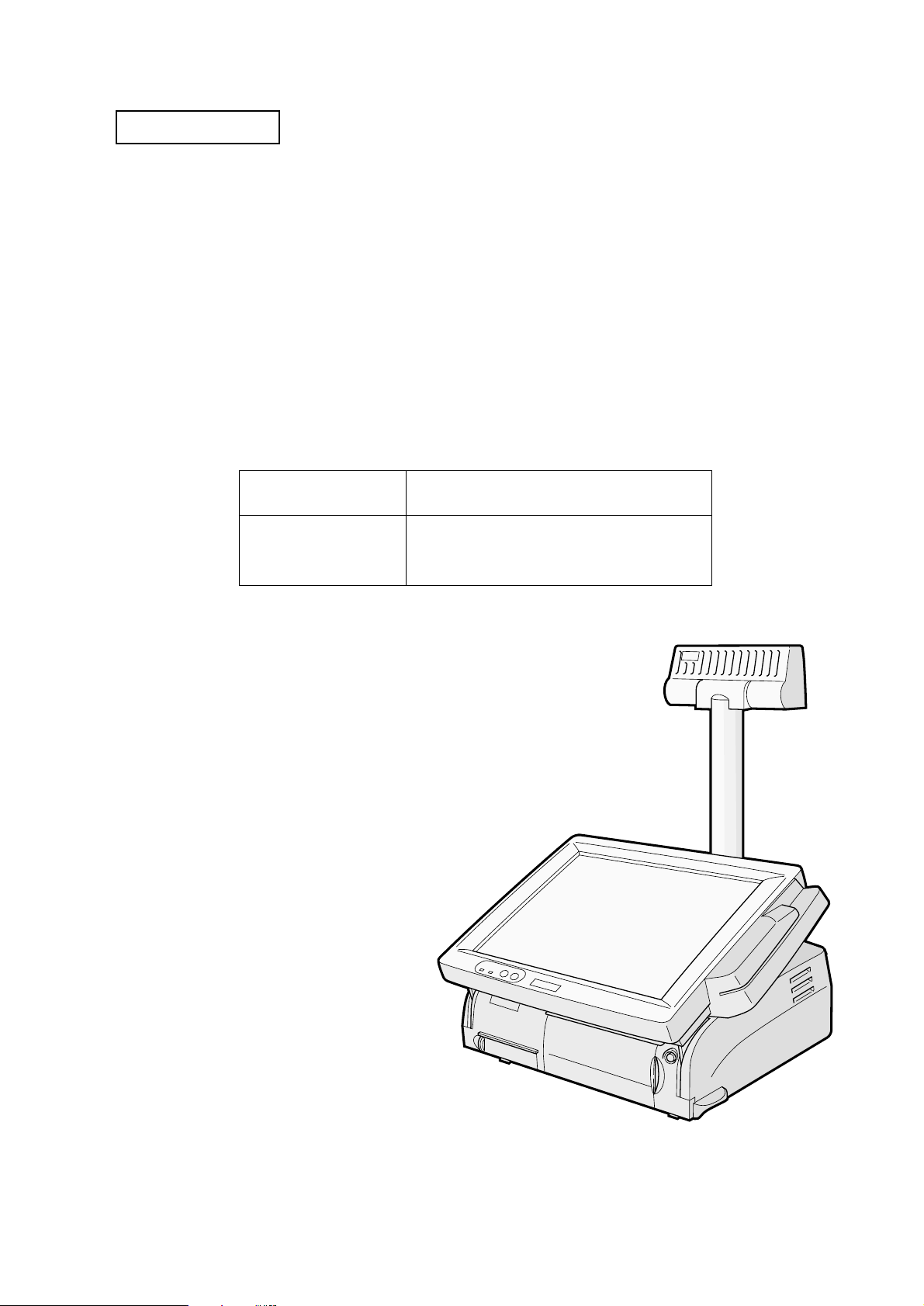
SR-600
EPSON
English
401333300
Page 2

Confidential
Page 3

Confidential
Table of content s
Revision Information . . . . . . . . . . . . . . . . . . . . . . . . . . . . . . . . . . . . . . . . . . . . . . . . . . . . iv
Warnings, Cautions, and Notes . . . . . . . . . . . . . . . . . . . . . . . . . . . . . . . . . . . . . . . . . . . iv
Guide Configuration . . . . . . . . . . . . . . . . . . . . . . . . . . . . . . . . . . . . . . . . . . . . . . . . . . .viii
Chapter 1 General Features
Features of the product . . . . . . . . . . . . . . . . . . . . . . . . . . . . . . . . . . . . . . . . . . . . . . . . . 1-1
Part Names . . . . . . . . . . . . . . . . . . . . . . . . . . . . . . . . . . . . . . . . . . . . . . . . . . . . . . . . . . . 1-5
Required Clearance . . . . . . . . . . . . . . . . . . . . . . . . . . . . . . . . . . . . . . . . . . . . . . . . . . . 1-11
Chapter 2 OS and Driver Setup
Supporting OS . . . . . . . . . . . . . . . . . . . . . . . . . . . . . . . . . . . . . . . . . . . . . . . . . . . . . . . . . 2-1
MS-DOS . . . . . . . . . . . . . . . . . . . . . . . . . . . . . . . . . . . . . . . . . . . . . . . . . . . . . . . . . . . . . . 2-1
Windows 95 . . . . . . . . . . . . . . . . . . . . . . . . . . . . . . . . . . . . . . . . . . . . . . . . . . . . . . . . . . . 2-4
Windows 98 . . . . . . . . . . . . . . . . . . . . . . . . . . . . . . . . . . . . . . . . . . . . . . . . . . . . . . . . . . . 2-9
Windows NT 4.0 . . . . . . . . . . . . . . . . . . . . . . . . . . . . . . . . . . . . . . . . . . . . . . . . . . . . . . 2-13
Windows2000 . . . . . . . . . . . . . . . . . . . . . . . . . . . . . . . . . . . . . . . . . . . . . . . . . . . . . . . . 2-20
Chapter 3 BIOS Setup
BIOS Setup Utility . . . . . . . . . . . . . . . . . . . . . . . . . . . . . . . . . . . . . . . . . . . . . . . . . . . . . 3-1
Power On Self Test (POST) . . . . . . . . . . . . . . . . . . . . . . . . . . . . . . . . . . . . . . . . . . . . . 3-11
Device Diagnostics Utility . . . . . . . . . . . . . . . . . . . . . . . . . . . . . . . . . . . . . . . . . . . . . . 3-15
Developer's Guide SR-600
Chapter 4 Driver / Utility Specifications
Network Driver . . . . . . . . . . . . . . . . . . . . . . . . . . . . . . . . . . . . . . . . . . . . . . . . . . . . . . . . 4-3
Video Driver . . . . . . . . . . . . . . . . . . . . . . . . . . . . . . . . . . . . . . . . . . . . . . . . . . . . . . . . . . 4-4
Log on (Software Keyboard) Utility . . . . . . . . . . . . . . . . . . . . . . . . . . . . . . . . . . . . . . 4-5
Screen Saver (For NT) . . . . . . . . . . . . . . . . . . . . . . . . . . . . . . . . . . . . . . . . . . . . . . . . . . 4-7
EPSON OPOS ADK . . . . . . . . . . . . . . . . . . . . . . . . . . . . . . . . . . . . . . . . . . . . . . . . . . . 4-11
Chapter 5 Hardware Specifications
Circuit Board Functions . . . . . . . . . . . . . . . . . . . . . . . . . . . . . . . . . . . . . . . . . . . . . . . . . 5-1
System . . . . . . . . . . . . . . . . . . . . . . . . . . . . . . . . . . . . . . . . . . . . . . . . . . . . . . . . . . . . . . . 5-2
Mother Board . . . . . . . . . . . . . . . . . . . . . . . . . . . . . . . . . . . . . . . . . . . . . . . . . . . . . . . . . 5-7
Power Supply Unit . . . . . . . . . . . . . . . . . . . . . . . . . . . . . . . . . . . . . . . . . . . . . . . . . . . . 5-11
Multi Video Mode . . . . . . . . . . . . . . . . . . . . . . . . . . . . . . . . . . . . . . . . . . . . . . . . . . . . 5-14
PCI Board . . . . . . . . . . . . . . . . . . . . . . . . . . . . . . . . . . . . . . . . . . . . . . . . . . . . . . . . . . . . 5-15
Power Supply Unit . . . . . . . . . . . . . . . . . . . . . . . . . . . . . . . . . . . . . . . . . . . . . . . . . . . . 5-16
FDD . . . . . . . . . . . . . . . . . . . . . . . . . . . . . . . . . . . . . . . . . . . . . . . . . . . . . . . . . . . . . . . . . 5-18
HDD . . . . . . . . . . . . . . . . . . . . . . . . . . . . . . . . . . . . . . . . . . . . . . . . . . . . . . . . . . . . . . . . 5-18
CD-ROM Drive(Optional) . . . . . . . . . . . . . . . . . . . . . . . . . . . . . . . . . . . . . . . . . . . . . . 5-19
CompactFlash Card(Optional or Specified Product) . . . . . . . . . . . . . . . . . . . . . . . 5-19
LCD/Keyboard unit . . . . . . . . . . . . . . . . . . . . . . . . . . . . . . . . . . . . . . . . . . . . . . . . . . 5-20
Chapter 6 Peripherals/Option Installation
LCD Unit . . . . . . . . . . . . . . . . . . . . . . . . . . . . . . . . . . . . . . . . . . . . . . . . . . . . . . . . . . . . . 6-2
CD-ROM Drive . . . . . . . . . . . . . . . . . . . . . . . . . . . . . . . . . . . . . . . . . . . . . . . . . . . . . . . 6-14
Drawer /CRT Board . . . . . . . . . . . . . . . . . . . . . . . . . . . . . . . . . . . . . . . . . . . . . . . . . . 6-17
Compact Flash Slot . . . . . . . . . . . . . . . . . . . . . . . . . . . . . . . . . . . . . . . . . . . . . . . . . . . . 6-23
MSR Unit . . . . . . . . . . . . . . . . . . . . . . . . . . . . . . . . . . . . . . . . . . . . . . . . . . . . . . . . . . . . 6-27
DM-D Unit . . . . . . . . . . . . . . . . . . . . . . . . . . . . . . . . . . . . . . . . . . . . . . . . . . . . . . . . . . . 6-44
Floppy Disk Drive . . . . . . . . . . . . . . . . . . . . . . . . . . . . . . . . . . . . . . . . . . . . . . . . . . . . 6-45
DIMM . . . . . . . . . . . . . . . . . . . . . . . . . . . . . . . . . . . . . . . . . . . . . . . . . . . . . . . . . . . . . . . 6-46
Rev.A i
Page 4

Confidential
Appendix 1 Interfaces
Connector Location . . . . . . . . . . . . . . . . . . . . . . . . . . . . . . . . . . . . . . . . . . . Appendix 1-1
Serial Port . . . . . . . . . . . . . . . . . . . . . . . . . . . . . . . . . . . . . . . . . . . . . . . . . . . Appendix 1-2
Parallel Port (LPT Port) . . . . . . . . . . . . . . . . . . . . . . . . . . . . . . . . . . . . . . . Appendix 1-3
Keyboard/Mouse Port . . . . . . . . . . . . . . . . . . . . . . . . . . . . . . . . . . . . . . . . Appendix 1-4
USB Port . . . . . . . . . . . . . . . . . . . . . . . . . . . . . . . . . . . . . . . . . . . . . . . . . . . . Appendix 1-5
Ethernet Port . . . . . . . . . . . . . . . . . . . . . . . . . . . . . . . . . . . . . . . . . . . . . . . . Appendix 1-6
Customer Display Port . . . . . . . . . . . . . . . . . . . . . . . . . . . . . . . . . . . . . . . . Appendix 1-7
CRT Port . . . . . . . . . . . . . . . . . . . . . . . . . . . . . . . . . . . . . . . . . . . . . . . . . . . . Appendix 1-8
Drawer Port . . . . . . . . . . . . . . . . . . . . . . . . . . . . . . . . . . . . . . . . . . . . . . . . . Appendix 1-9
Floppy Disk Drive Connector . . . . . . . . . . . . . . . . . . . . . . . . . . . . . . . . . Appendix 1-10
PCI Slot . . . . . . . . . . . . . . . . . . . . . . . . . . . . . . . . . . . . . . . . . . . . . . . . . . . . Appendix 1-11
Appendix 2 Power Management
Description . . . . . . . . . . . . . . . . . . . . . . . . . . . . . . . . . . . . . . . . . . . . . . . . . . Appendix 2-1
Suspend . . . . . . . . . . . . . . . . . . . . . . . . . . . . . . . . . . . . . . . . . . . . . . . . . . . . Appendix 2-3
Video Off . . . . . . . . . . . . . . . . . . . . . . . . . . . . . . . . . . . . . . . . . . . . . . . . . . . Appendix 2-6
Front Power Switch Function . . . . . . . . . . . . . . . . . . . . . . . . . . . . . . . . . . Appendix 2-8
Recommended Setting according with Operation . . . . . . . . . . . . . . . . Appendix 2-12
Restrictions . . . . . . . . . . . . . . . . . . . . . . . . . . . . . . . . . . . . . . . . . . . . . . . . . A ppendix 2-12
Appendix 3 Wake On LAN
Descriptions . . . . . . . . . . . . . . . . . . . . . . . . . . . . . . . . . . . . . . . . . . . . . . . . . Appendix 3-1
Software Setting . . . . . . . . . . . . . . . . . . . . . . . . . . . . . . . . . . . . . . . . . . . . . . Appendix 3-3
Function Details . . . . . . . . . . . . . . . . . . . . . . . . . . . . . . . . . . . . . . . . . . . . . . Appendix 3-5
Appendix 4 COM3 Mode
Description . . . . . . . . . . . . . . . . . . . . . . . . . . . . . . . . . . . . . . . . . . . . . . . . . . Appendix 4-1
COM3 Mode Seting Specification . . . . . . . . . . . . . . . . . . . . . . . . . . . . . . . Appendix 4-2
INDEX . . . . . . . . . . . . . . . . . . . . . . . . . . . . . . . . . . . . . . . . . . . . . . . . . . . . . . . . . . . .Index-1
ii Rev.A
Page 5

Confidential
Developer's Guide SR-600
CONFIDENTIALITY AGREEMENT
BY USING THIS DOCUMENT, YOU AGREE TO ABIDE BY THE TERMS OF THIS AGREEMENT. PLEASE
RETURN THIS DOCUMENT IMMEDIATELY IF YOU DO NOT AGREE TO THESE TERMS.
❏ This document contains confidential, proprietary information of Seiko Epson Corporation or its affiliates. You
must keep such information con fidential. I f the user is a b usine ss entit y or organiz ation, you must limit disclosur e
to your employees, agents, and contractors who have a need to know and who are also bound by obligations of
confidentiality.
❏ On the earlier of (a) termination of your relationship with Seiko Epson, or (b) Seiko Epson’s request, you must
stop using the confidential informa ti on. You must th en ret urn or de st roy th e informa ti o n, as dir ected by Seiko
Epson.
❏ If a court, arbitrator, government agency, or the like orders you to disclose any confidential information, you
mustimmediately notify Seiko Epson. You agree to give Seiko Epson reasonable cooperation and assistance in
resisting disclosure.
❏ You may use confidential information only for the purpose of facilitating authorized sales and service of, or
developing software and similar products for authorized use with, the products to which the document relates,
unless you obtain the prior written consent of Seiko Epson for some other use.
❏ Seiko Epson warrants that it has the right to disclose the confidential information. SEIKO EPSON MAKES NO
OTHER WARRANTIES CONCERNING THE CONFIDENTIAL INFORMATION OR ANY OTHER
INFORMATION IN THE DOCUMENT, INCLUDING (WITHOUT LIMITATION) ANY WARRANTY OF TITLE
OR NON-INFRINGEMENT. Seiko Epson has no liability for loss o r damage arisi ng from or relating t o your use of
or reliance on the information in the document.
❏ You may not reproduce, store, or transmit the confidential information in any form or by any means (electronic,
mechanical, photocopying, recording, or otherwise) without the prior written permission of Seiko Epson.
❏ Your obligations under this Agreem en t a re in addi tion to a ny ot her lega l obl iga ti ons. Seiko Epson does not waive
any right under this Agreement by failing to exercise it. The laws of Japan apply to this Agreement.
CAUTIONS
❏ This document shall apply only to the product(s) identified herein.
❏ No part of this document may be reproduced, stored in a retrieval system, or transmitted in any form or by any
means, electronic, mechanical, photocopying, recording, or otherwise, without the prior written permission of
Seiko Epson Corporation.
❏ The contents of this document are subject to change wi thout notice. Please contact u s f or the latest information.
❏ While every precaution has been taken in the prepara ti on of this d ocumen t, Seik o Epson Corpora t ion a ssumes no
responsibility for errors or omissions.
❏ Neither is any liability assumed for damages resulting from the use of the information contained herein.
❏ Neither Seiko Epson Corporation nor its affiliates shall be liable to the purchaser of this product or third parties
for damages, losse s, cos ts, or expen ses inc urred by t he purc hase r or t hird parties a s a r esul t of: a cciden t, mi suse, or
abuse of this product or unau thoriz ed modifi cati ons, r epairs, or alterations to this product, or (ex cluding t he U.S .)
failure to strictly comply with Seiko Epson Corporation's operating and maintenance instructions.
❏ Seiko Epson Corporation shall not be liable against any damages or problems arising from the use of any options
or any consumable products other than those designated as Original EPSON Products or EPSON Approved
Products by Seiko Epson Corporation.
TRADEMARKS
EPSON ® is a registered trademark of Seiko Epson Corporation.
General Notice: Other product and company names used herein are for identification purposes only and may be
trademarks of their respective companies.
Rev.A iii
Page 6
Confidential
Revision Information
Revision Page Altered Item and Contents
Rev. A
Warnings, Cautions, and Notes
Notes and precautions in this manual are identified as defined below.
WARNING:
Provides information that must be followed carefully to avoid bodily injury.
CAUTION:
Provides information that must be observed to pr event damage to the equipment or
loss of data.
❏
Possibility of sustaining physical injuries.
❏
Possibility of causing physical damages.
❏
Possibility of causing information loss.
Note:
Provides important information and useful tips on handling the equipment.
iv Rev.A
Page 7

Confidential
Developer's Guide SR-600
Safety Precautions
This section presents important information intended to ensure safe and effective use of this
product. Please read this section carefully and store it in an accessible location.
WARNING:
❏
Turn off the main power switch immediately and unplug the power cord if the SR-600
produces smoke, a strange odor, or unusual
electric shock. Contact your dealer or an EPSON service center for advice.
❏
Never attempt to repair this product yourself. Improper repair work can be
dangerous.
❏
Never disassemble or modify this product. Tampering with this product may result in
injury, fire, or electric shock.
❏
Be sure to use the specified power supply. Using an unsuitable power supply may
cause fire or electric shock.
❏
Never insert or disconnect the power plug with wet hands. Doing so may result in
severe shock.
. Continued use may lead to fire or
noise
❏
Do not allow foreign objects to fall into this product. Penetration by foreign objects
may lead to fire or shock.
❏
Do not plug too many leads in to a single socket. It may lead to fire.
❏
Handle the power cord with care. Improper handling may lead to fire or shock.
❏
Do not modify or attempt to repair the cord.
• Do not process the power cord.
• Do not place any object on top of the cord.
• Avoid excessive bending, twisting, and pulling.
• Do not place the cord near heating equipment.
• Check that the plug is clean before plugging it in.
• Be sure to push the pron gs all the way in.
Rev.A v
Page 8
Confidential
CAUTION:
❏
Be sure your power cable meets the relevant safety standards and includes a
power-system ground terminal (PE terminal). Impro per inter connect ions may lea d to
crash or fire.
❏
Be sure to set this product o n a firm, stable and horizontal surface. The product may
break or cause injury if it falls
❏
Do not use in locati ons subjec t to h igh humi dity o r dust l evels. E xcess ive humid ity an d
dust may cause equipment damage, fire, or shock.
❏
Do not place multiple loads on the power outlet (wall outlet). Overloading the outlet
may lead to fire.
❏
To ensure safety, unplug this product prior to leaving it unused for an extended
period.
Note:
❏
Be sure to use the EPSON supplied DIMM, HDD and CPU.
.
❏
To get the lastest information about which Compact Flash and PCI board can be used with
this product, contact your EPSON dealer.
Note for Maintenance, Repair, and Inspection
WARNING:
❏
Wear a ground wristlet to prevent the system f ailure from the static electricity durin g
the handling of the internal circuit board.
❏
If you remove the internal circuit board, place the circuit board on the antistatic
rubber surface or equivalent product to prevent the system failure from the static
electricity.
❏
Handle the power cord with care, improper handling may lead to fire.
❏
Do not modify or attempt to repair the cord.
❏
Do not operate the maintena nce, repa iring or ins pection t o avoid the electr ic shock
when it’s thunderstorming.
❏
It is possible that the temperature of the circuit board device is high. Besure to wait
for about 10 minutes after turned off the power to handle the circuit board device.
❏
Do not give the circuit board impacts or vibrations. It may result in the system failure.
❏
Do not touch the circuit board or cable termi nals. It may cause the system failure
from the dirt.
vi Rev.A
Page 9
Confidential
❏
Never clean the product with thinner, benzene, alcohol or other such
result in deformation or breakage of the plastic and rubber made supplies of this
product.
❏
Clean this product with dry or wettish fabric. Be sure to unplug the power cord
before clean this product.
Developer's Guide SR-600
solvent.
Note for Deacquisition
Note:
Follow the country(or local) law and the regulation for the disposal of this product.
Modular Type Connector
Be careful not to cut your finger on any edge of he unit.The Caution label as shown below is
sticked around the three modular type connector on the rear and bottom sides of this product.
CAUTION:
It may
The modular type connector is used as a dedicated connector for cash drawer or customer
display. Do not connect it with the public circuits, Network, or LAN. It does not operate as an
Ethernet Connector.
Rev.A vii
Page 10

Confidential
Guide Configuration
Aim of the Manual
This manual was created to provide information on the
programs, and setting upthe optional supplies and the printer.
SR-600
Contents of the Manual
The configurations of this manual is summarized in the table below.
Chapter 1 “General Features"
Chapter 2 “OS and Driver Setup”
Chapter 3 “BIOS Setup”
Chapter 4 “Driver / Utility
Specifications”
Chapter 5 “Hardware Specifications”
Chapter 6 “Peripherals/Option
Installation”
Gives descriptions of SR-600 and the parts
names.
Gives descriptions of the OS and the Driver
compliant with each OS.
Gives descriptions of the BIOS, POST, and the
Device Diagnostic Utility.
Gives specifications for the Drivers and
Utilities.
Gives specifications for the Hard ware
configurations and the optional supplies.
Gives specifications for the opti onal periph erals
and setup.
for anyone who is developing
Appendix 1 “Interfaces”
Appendix 2 “Power Management”
Appendix 3 “Wake On LAN”
Appendix 4 “COM3 Mode”
Gives specifications for all the interfaces.
Gives specifications for the Po wer Manag ement
Function.
Gives specifications for the Wake On LAN
function.
Gives descriptions of th e COM3 Mode.
Related Manuals
Related Manuals
Name Contents
SR-600 User’s Manual Gives basic handling guidelines of SR-600.
SR-600 Service Manual Gives guidelines for anyone who supports and repairs SR-600.
viii Rev.A
Page 11

Confidential
Chapter 1
General Features
Features of the product
Hardware Configurations
The SR-600 is an intelligent terminal developed for the POS environment.
The SR-600 has the following features:
❏
A high speed Intel Celeron processor provides the power and speed necessary for data
processing.
❏
Using it with a variety of options and
suits your needs best.
❏
Designed with a stylish color and shape, it is waterproof and easy to care for.
❏
The lock on the front cover allows only the key owner to take out a CD-ROM
peripheral devices allows you to construct a system that
Developer's Guide SR-600
.
❏
The power management function supplies only the amount of power
processing, assuring optimum power saving.
❏
Use of PC/AT compatible BIOS.
❏
Support of Plug & Play function. (Windows 98/2000 only)
❏
Wake up function can be available over a LAN.
❏
Use of design consistent with the EPSON POS system DM series Customer Display. A
customer display can be mounted on the SR-600, so it does not occupy much space.
❏
Two disk spaces are provided for HDD, CD-ROM, and/or CompactFlash.
❏
A 2.5-inch hard disk drive can be stored in hard disk drive.
❏
The PC-based open architecture with a PCI slot increases system
❏
Three serial ports, one parallel port, and two USB port allow connection of
devices, increasing system expandability.
❏
An Ethernet controller can be used to 100Base-TX or 10Base-T
❏
A CompactFlash board can be installed.
❏
The built-in IBM PS 2 keyboard port supports IBM PC/AT
.
compatible keyboards.
necessary for data
expandability.
peripheral
❏
A CD-ROM drive can be installed.
❏
LCD unit (option) is a 12.1-inch TFT with Touch Panel or can be selected from DSTN
allows you to make a free layout for the appli cation screen.
❏
A 2MB video memory is internally equipped using a PCI video controller.
Rev.A General Features 1-1
, which
Page 12

Confidential
Software Configurations
BIOS setup
BIOS setup defines your system configuration. When you set up the product for the first time,
run this program to set the system environment. When you want to chang e the operating
environment, run this program again. For details on BIOS setup, refer to “Chapter 3, BIOS
Setup.”
Device self-dia gn o s is uti lity
Device self-diagnosis utility performs a test on each devices and functions of the SR-600. For
details on device self-diagnosis utility, refer to “Chapter 3, BIOS Setup.”
1-2 General Features Rev.A
Page 13

Confidential
Operating System
SR-600
The
•Windows 95
•Windows 98
• Windows NT Workstation 4.0
•MS-DOS 6.2
• Windows 2000 Professional (It’ll be available in the near future.)
runs on the standard Microsoft ® operating systems:
Developer's Guide SR-600
Rev.A General Features 1-3
Page 14

Confidential
Peripheral Devices
SR-600
The
❏
LCD units
12.1” color DSTN Model Name DM-LS121S
12.1” color TFT Model Name DM-LS121T
❏
MSR units
ISO I track 1,2,3 Model NameDM-MS123
❏
Floppy disk drive
3.5” 720KB/1.44MB Model Name OI-S01
❏
CD-ROM drive Model Name OI-S02
❏
Drawer board
Cash drawer x 2 port Model Name OI-B08
CRT x 1 port
❏
CompactFlash board
For HDD attachment Model Name OI-S03-012
For CD-ROM attachment Model Name OI-S03-022
can be configured with the following optional units:
1-4 General Features Rev.A
Page 15
Confidential
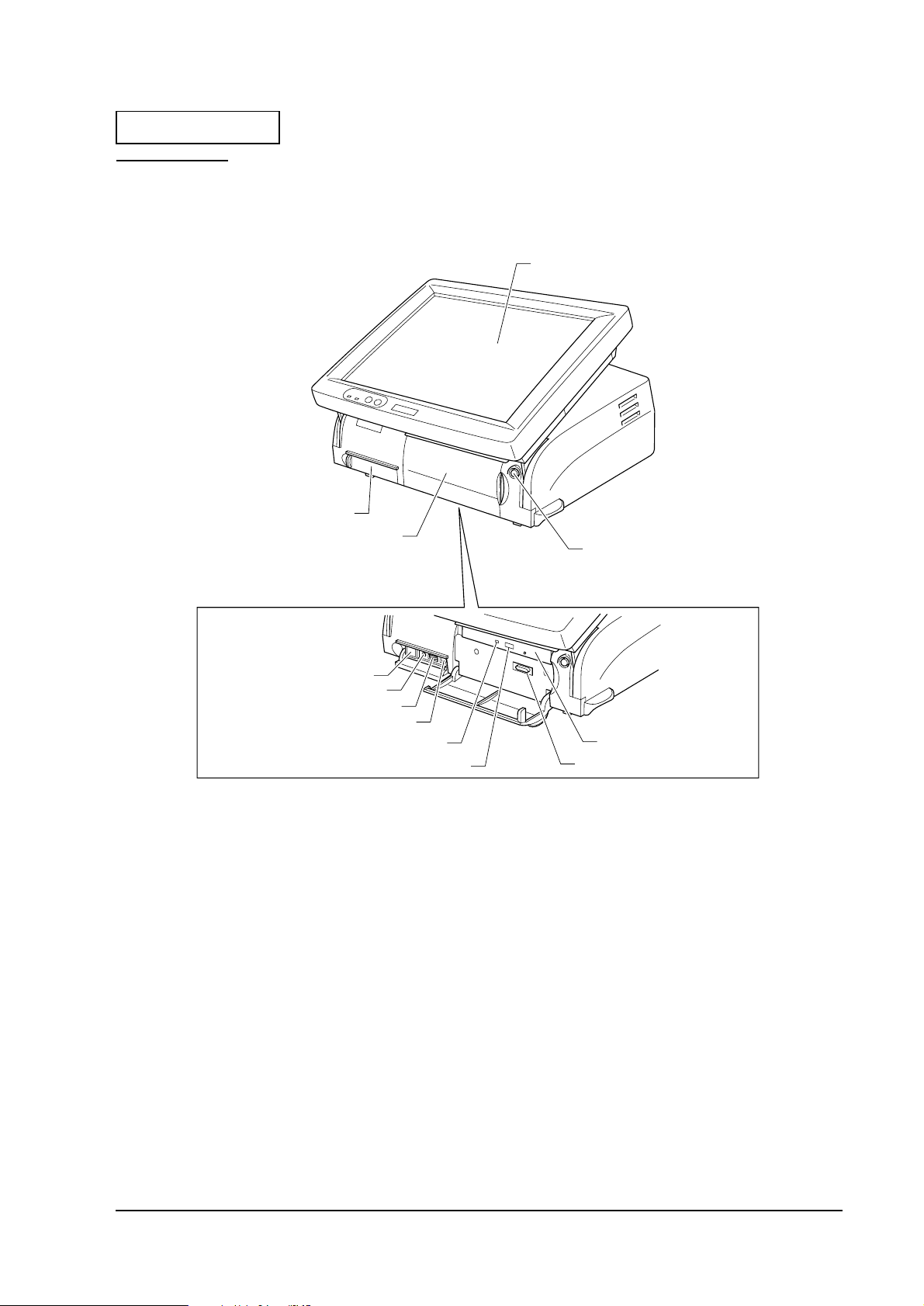
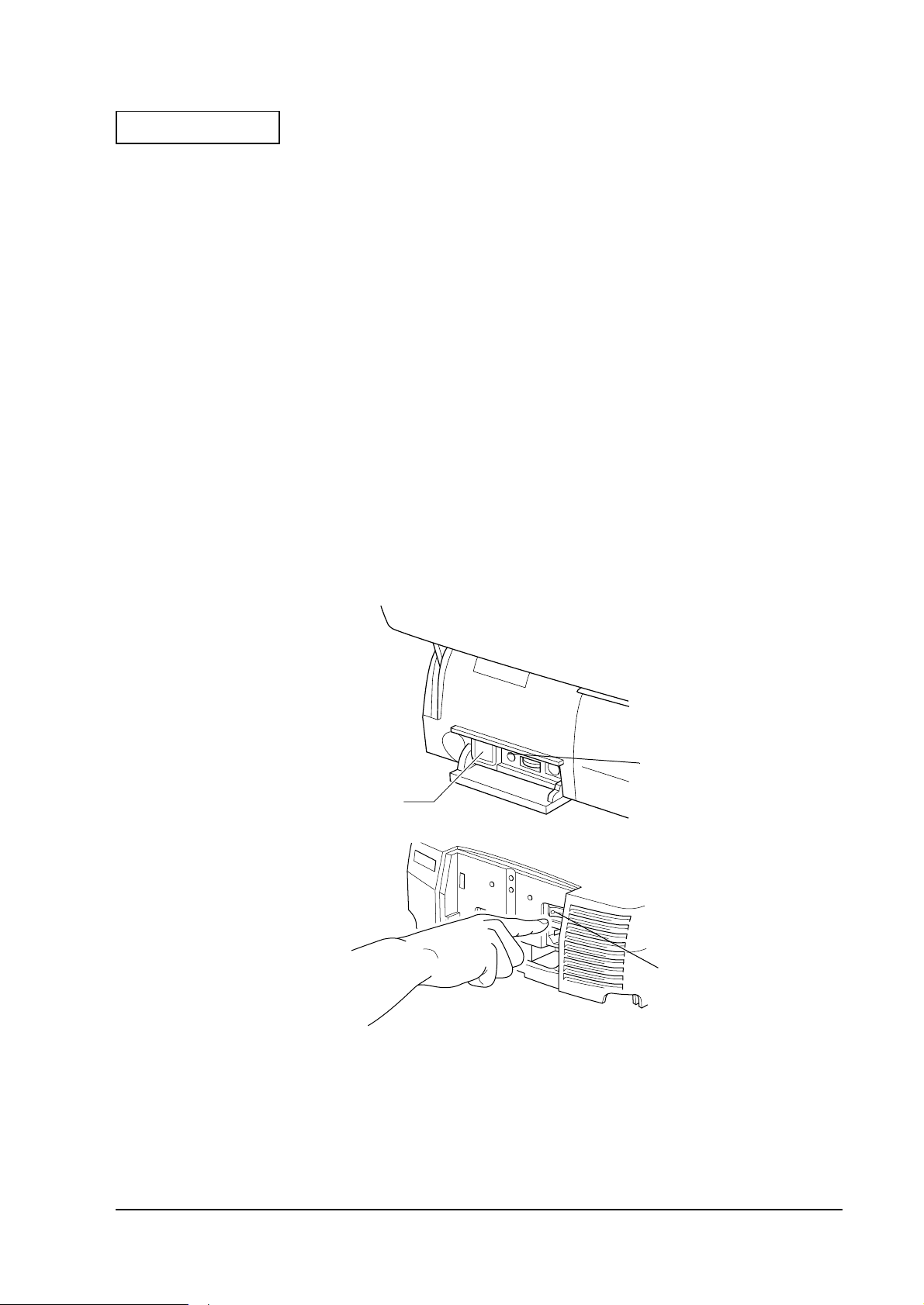
Part Names
Front View
Developer's Guide SR-600
LCD Unit
Switch Cover
CD Cover
Key Lock
Front Power Switch
Reset Switch
Speaker Volume
K/B Mouse Connector
CD-ROM Access LED
CD-ROM Eject Button
Figure 1-1 Front views of the SR-600
CD-ROM Drive
FDD Connector
Rev.A General Features 1-5
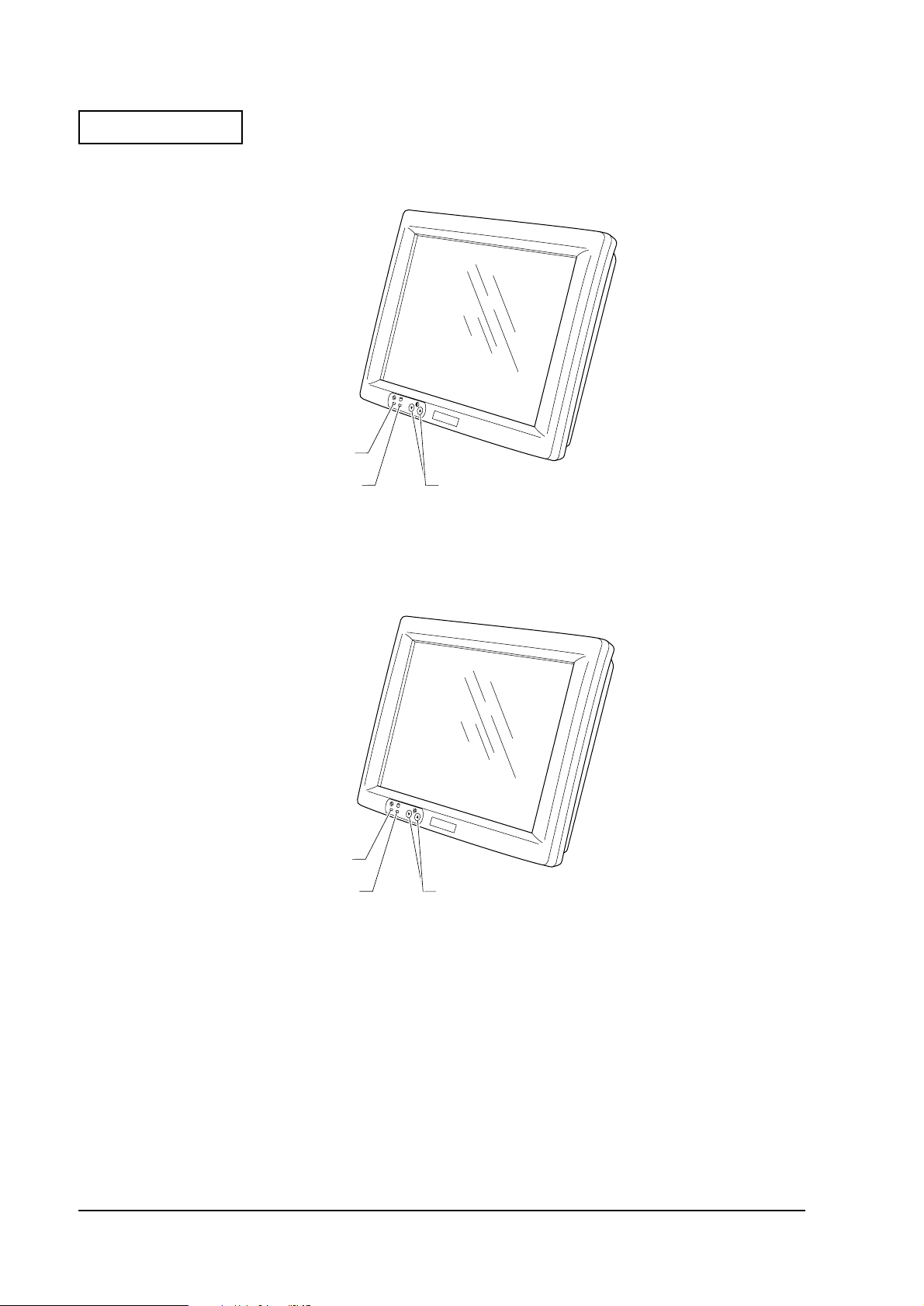
Page 16
Confidential
DM-LS121S
Power LED
DM-LS121T
HDD LED
Contrast Adjustment
Switch
Figure 1-2 External views of the DM-LS121S
Power LED
HDD LED
Backlight Brightness
Adjustment Switch
Figure 1-3 External views of the DM-LS121T
1-6 General Features Rev.A
Page 17
Confidential
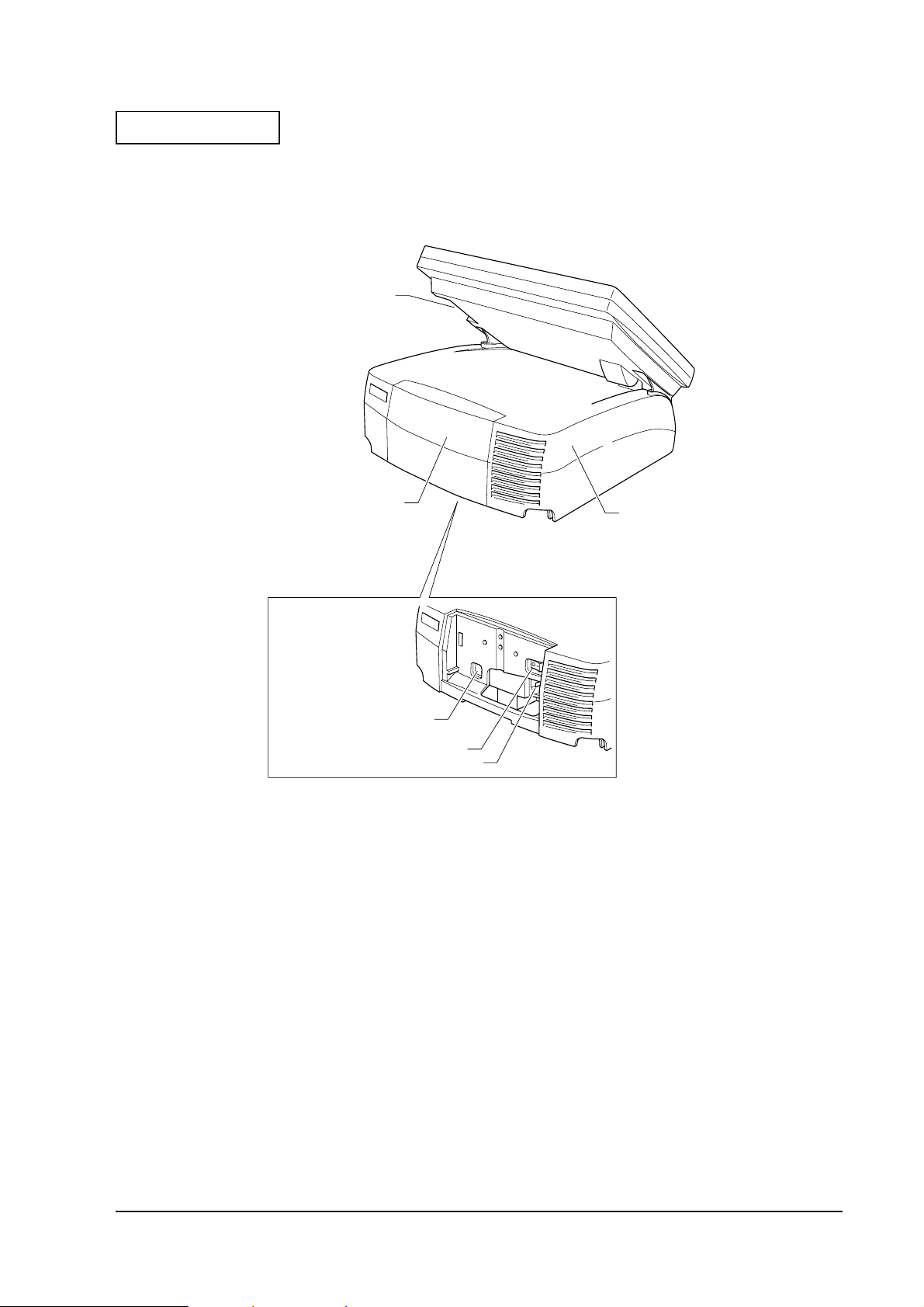
Rear View
Developer's Guide SR-600
MSR Unit
Connector
Rear Cover
Customer Display
Connector
Main Power Switch
Main Power Connector
Figure 1-4 Rear views of the SR-600
Main Cover
Rev.A General Features 1-7
Page 18
Confidential
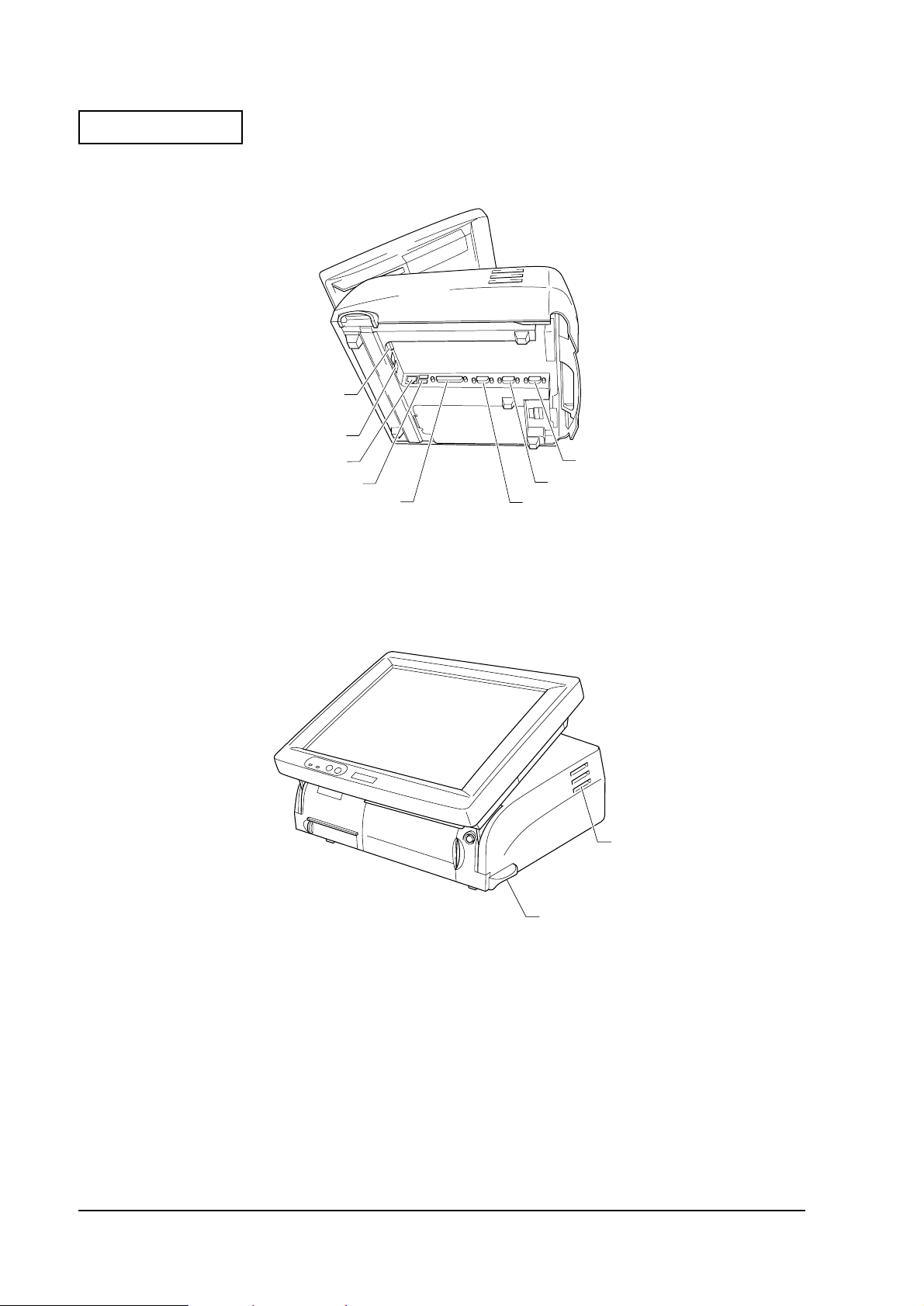
Bottom View
:
*Drawer Kick Connector
*CRT Connector
Ethernet Connect or
USB Connector
Figure 1-5 Bottom views of the SR-600
LPT
COM1
COM2
COM3
* CRT and drawer kick connector is used if the optional CRT/drawer board is installed.
LCD Angle Adjusment
Lever
Figure 1-6 Side views of the SR-600
Ventilator
1-8 General Features Rev.A
Page 19
Confidential
Switches
❏
Front power switch
The front power switch is a push type switch on the bottom of the left side corner under the
switch cover. It turn s o n an d o ff t he sys tem. The fro nt p ower s wit ch i s pl ace d un der the f ront
cover to prevent the operation mistake from being turning off accidentally. It changes the
front power status of SR-600 to power on, standby, or off. The functionality of the front
power switch is determined by BIOS Setup utiliy.
❏
Main power switch
The main power switch on the back of the SR-600 isolates the AC line voltage from the
power supply. Rem ove t he rea r cov er to turn on and o ff t he main pow er. D uring the n ormal
use, this switch is left on.
❏
Reset Switch
The reset switch under the switch cover by the right side of the front power switch resets the
hardware of the SR-600. I f the sy stem han gs for any reas on and cannot r ecover, p ressing t his
switch restarts the system.
Developer's Guide SR-600
Front Power
Switch
Figure 1-7
Switch locations
Reset Switch
Main Power
Switch
Rev.A General Features 1-9
Page 20
Confidential
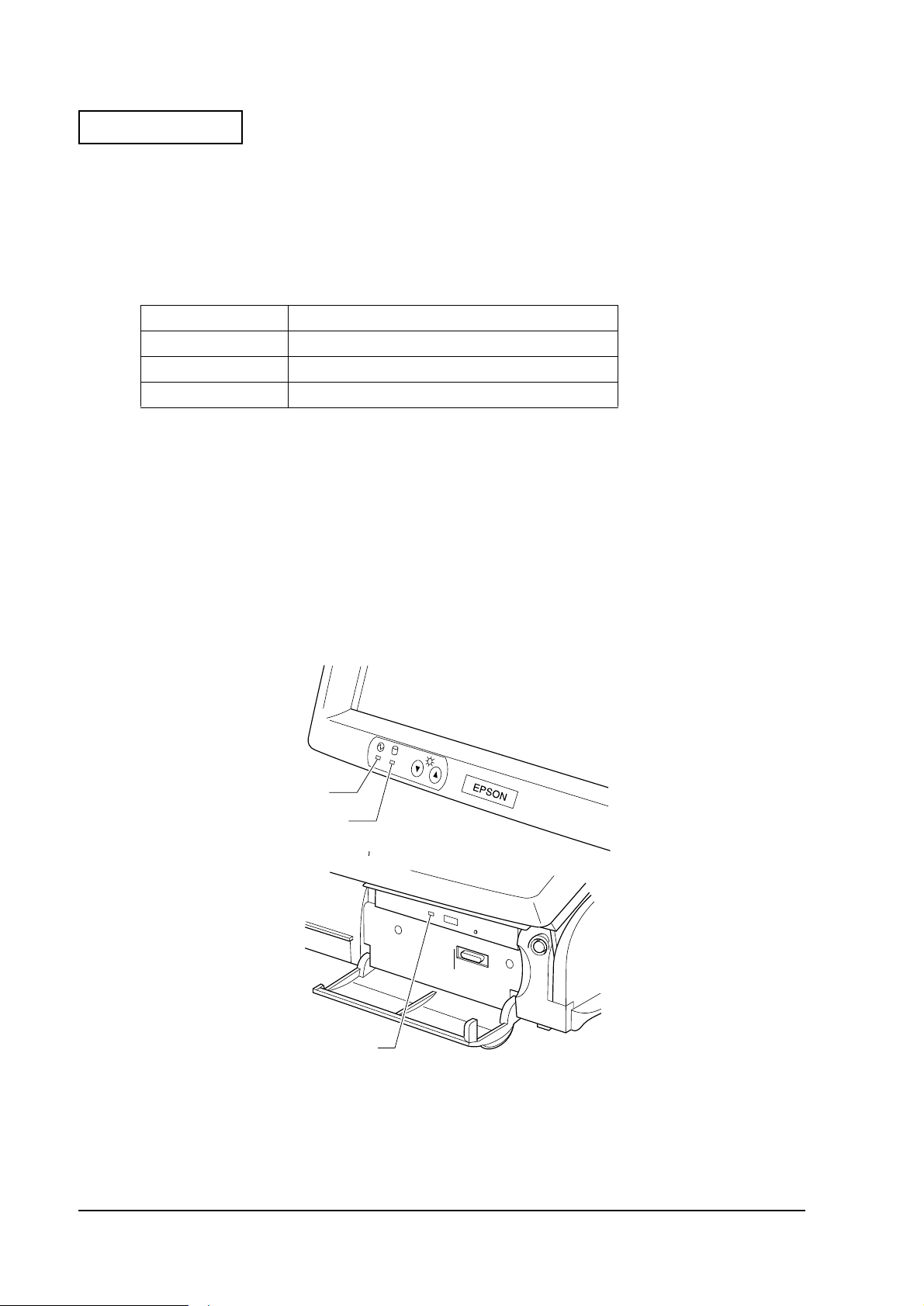
Indicators
❏
Power LED
The power LED on the LCD unit indicates the on/off status of the power supply. The table below
shows the colors of the LED and its meaning.
Table 1-1 Power LED colors and their meaning s
LED color Meaning when illuminated
Green Power supply is on (during normal operations)
Orange
Off Power is off
❏
HDD LED
Power is suspended
hows the col ors
HDD LED (Green) on the LCD unit indicates the access status of the HDD or CF. The
meaning of the LED is same in all the units.
It also lights while accessing to other devices (CD-ROM or CF) which connected to Primary
IDE.
❏
CD-ROM Access LED
CD-ROM access LED on the CD-ROM unit lights green while the CD-ROM is being
accessed.
Power LED
HDD LED
CD-ROM
Access LED
Figure 1-8 Location of LEDs
1-10 General Features Rev.A
Page 21
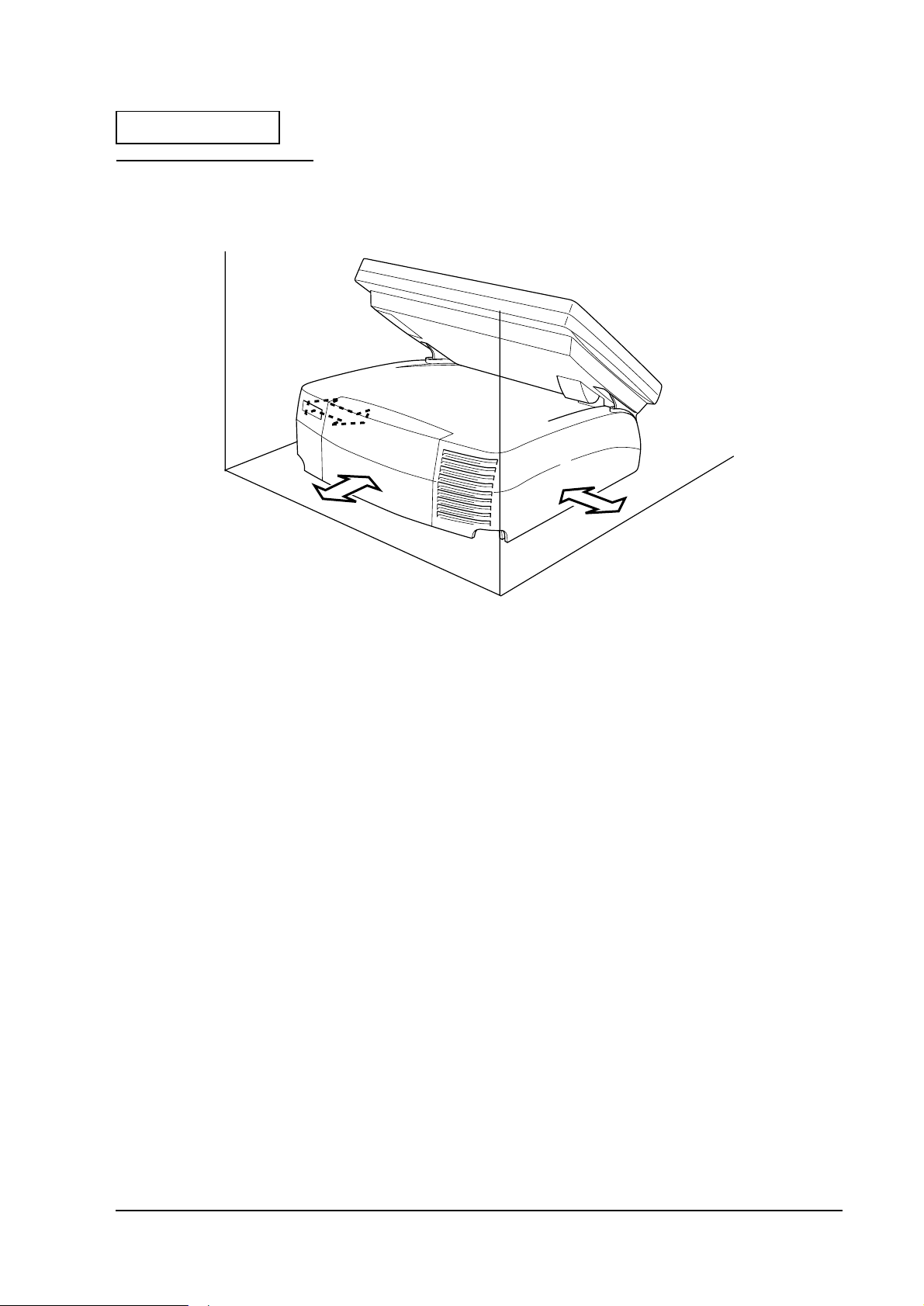
Confidential
Required Clearance
Developer's Guide SR-600
5cm
5cm
Rev.A General Features 1-11
Page 22

Confidential
1-12 General Features Rev.A
Page 23

Confidential
Chapter 2
OS and Driver Setup
Supporting OS
SR-600 is supporte d with following OS listed below.
• MS-DOS 6.2 (See section 2-1.)
• Microsoft Windows 95 (See section 2-4.)
• Microsoft Windows 98 (See section 2-9.)
• Microsoft Windows NT Workstation 4.0 (See section 2-13.)
• Microsoft Windows 2000 (It will be supported in the near future) (See section 2-20.)
MS-DOS
Developer's Guide SR-600
Accompanying Software
The software listed below is pre-installed in the system. The utilities setup is not performed.
Also, the langu age indicated in the parentheses is available. If your language for the utilities is
not available, English is used instead. For example, English version of DM-MS series utility
setting is attached as a substitute for French version of MS-DOS.
• Microsoft MS-DOS 6.2 (Japanese and other language edition : 6.20/V
Foreign edition : 6.22)
• Fujitsu Touch Panel Driver 1.0 (English)
• Realtec Network Driver 3.80 (English)
• Matsushita CD-ROM Driver 98/05/08 version (Japanese/English)
• EP SON DM-MSE series Setup Utility 1.00 (English)
Rev.A OS and Driver Setup 2-1
Page 24

Confidential
Directory Configurations
The directory configurations of Pre-installed HD Setup Drive are as follows. Volume label for
Japanese edition is "MS-DOS_6", and for other languages is "MS-DOS_6_22". Required capacity
is approximately 7MB.
\ : Bootup File
+-- BACKUP
| +-- CDROM : CD-ROM Driver Backup
| +-- MSRCFG : DM-MS series Setup Utility
| +-- NETWORK : Network Driver Backup
| | +-- MSLANMAN
| | | +-- DRIVERS
| | | | +-- ETHERNET
| | | | | +-- RTL8139
| | | | +-- NIF
| | | +-- NWCLIENT
| | | | +-- DOS
| +-- TOUCH : Touch Panel Driver Backup
+--DOS : System File
Refer to “HDVER.TAG” on the Setup Drive root to conf irm the HD version. The contents is as
follows. This file is saved in Text format and can ch eck from the EDIT. Available LANG
(language) is Japanese, English, German, French, Italian, Spanish, Dutch, Korean, Chinese
Traditional, or Chinese Simplified. VER (Version) is organized in three sets of number
combination such as "1.00.1".
[HD Information]
MODEL=IM-600
OS=MS-DOS6.2
LANG=English
VER=1.00.1
Touch Panel Driver
The Touch Panel Driver is not installed when th is unit is shipped. Simple Batch File for copying
is available. Copy it from the backup directory to use. Move the Batch File to
“C:\BACKUP\TOUCH" and type the command written below to start installation.
INSTALL C:\TOUCH[Enter]
The directory where the file is copying to can be specified to the parameter as an option, and also
can be omitted. If it is omitted, the file is copied to “C:\TOUCH". It automatically copies the file
and completes the file copying.
2-2 OS and Driver Setup Rev.A
Page 25

Confidential
Type the command written below on the prompt to install the driver.
MEDVSTD I10,P2E8,B96[Enter]
Parameter “I10" specifies IRQ 10, “P2E8" specifies I/O address 2E8h, and “B96" specifies Baud
Rate 9600.
The calibration method is as follows.
1. Move to the Touch Pane l directory.
2. Type “EPCAL” then press [Enter]. Calibration utility starts.
3. Click on the points on the [+] character. The [+] character is displayed sequentially in nine
places on the screen (Top : left/middle/right, Middle : left/middle/right, Low : left/
middle/right).
4. It automatically exits the utility when the procedure is completed.
Developer's Guide SR-600
Network Driver
The driver for Microsoft Lan Manager is stored in “C:\BACKUP\NETWORK\MSLANMAN"
directory, and the driver for Novell Netware is stored in
“C:\BACKUP\NETWORK\NWCLIENT” directory. The installation instruction is ind icated in
“MSLANMAN/MSLANMAN.TXT” for Microsoft Lan Manager Drive, and “NWCLIENT/
NWODIDOS.TXT” for Novell Netware Drive. Refer to those instructions for the installation.
The directories explained above is for backup and is not a directory configuration of the
document. Make sure to create an appropriate directory, then proceed the copying of the file.
CD-ROM Driver
The CD-ROM Driver is not installed when this un it is shipped. Follow the steps bel ow to install
the CD-ROM Driver.
1. Start “C:\BACKUP\CDROM\INSTALL.EXE”.
2. The Installation Menu Screen is displayed.
Ordinarily, item 2 is selected.
3. “AUTOEXE.BAT” Updated Selection screen is displayed.
Press “Y" then [Enter].
4. Start the searching of the fie then exit.
The searching of the file is a required process for Windows, but not necessary for MS-DOS.
Rev.A OS and Driver Setup 2-3
Page 26

Confidential
Windows 95
Accompanying Software
The software listed below is pre-installe d in the system. The language indicated in the
parentheses is available. All the languages are not prepared for the utilities. English is used as a
substitute for un available languages. For ex ample, English version of DM-MS series utility
setting is attached as a substitute for French version of MS-DOS.
• Microsoft Windows 95 950B (OSR2.1, all available languages)
• Microsoft Windows 95 Supplement (USB Supplement/Y2K Supplement/MS-IME97/
IME 97 Updater/IrDA INF File etc, each languages)
• INTEL Chipset INF Utility 2.20.0006 (English)[Note 1]
• EPSON Touch Panel Driver 1.00 (English)
• Chipset & Technologies Display Driver 4.11.01.2500 (all available languages)
• Realtec Network Driver 5.374.0214.2000 (English)[Note 2]
• EP SON DM-MS series Setup Utility 1.00 (Win version, English), 1.00 (DOS ve rsion,
English)[Note 2]
• EPSON Logon Utility 1.02 (English)[Note 2]
• EPSON OPOS ADK 1.96 (Japanese/English)[Note 2]
• EPSON TM Driver 2.01 (Japanese/English/Chinese Traditional/Chinese
Simplified)[Note 2]
[Note 1]Required to recognize the bridge, USB Controller, and IDE Controller. Set up is completed.
[Note 2]It is not setup.
2-4 OS and Driver Setup Rev.A
Page 27

Confidential
Developer's Guide SR-600
Directory Configurations
The directory configurations of setup drive are as follows. Volume label is "Windows 95" and
the initial required capacity is approximately 400MB.
\ : Bootup File, Version File (Note 1)
+-- BACKUP
| +-- CHIPSET : Chipset INF Utility Backup
| +-- MSRCFG : MSR Setup Utility Backup
| | +-- DOS : for DOS
| | +-- WIN : for Windows
| +-- LOGON : Software Keyboard Utility Backup
| +-- NETWORK : Network Driver Backup
| +-- OPOSADK : OPOS ADK Backup
| +-- RECOVERY : Recovery Media Backup
| | +-- DATA
| | | +-- RESTORE
| | +-- BOOTFD
| | +-- DATA
| +-- TOUCH : Touch Panel Driver Backup
| +-- TMDRV : TM/DM Driver Backup
| +-- VIDEO : Video Driver Backup
| +-- WIN95SUP : Supplement Backup
+-- ProgramFiles : Windows 95 Utility
+-- WINDOWS : Windows 95 File
Note 1)The contents of Version File (HDVER.TAG) are as follows.
[HD Information]
MODEL=IM-600: Model Name
OS=Windows95: OS Name
LANG=Englis h : Lan guage = English
Japanese
German
French
Italian
Spanish
Dutch
Korean
Chinese Traditional
Chinese Simplified
Rev.A OS and Driver Setup 2-5
Page 28
Confidential
Initial Setup
The environment setting is proceeded following the steps below when you turn on the PC.
1. The program prompts you to enter the Windows owner’s name and the comapny name.
Enter the names and press the Next button.
2. The Software Licensing Agreement is displayed. Check on the [Agree] radio box and press
the Next button.
3. The program prompts you to enter the Product Key. Enter the product key listed on the
front page of First Step Guide contained in the COA(Certificate of Authenticity) package
supplied with OS package, then press the Next button.
4. Information data input is completed. Press the [Done] button.
5. Set the Date, Time, and Time Zone.
Make sure to s et the correct date and t im e. The standard setting may not match with you r
environment.
6. Printer setup.
It is not necessary to setup the printer here. You can se tup the printer later.
7. Tour utility is executed.
The document about the Y2K is displayed after the execution of tour utility. Read the
document and install it if it’s necessary.
CAUTION:
65536 colors is already set for DSTN LCD model same as TFT LCD model.
It performs setup for SR-600 when it is initially setting up. Therefore, it takes additional 20
to 30 seconds to display the Windows desktop.
Device recognition is performed for the initial setup depending on the system
configuration (change in system configuration, not connectiing PS2 Mouse, etc). It may
require a Driver file depending on the device. Follow the installation steps below or th e
manual comes with device for the installation.
From the second setup, the warning dialog “Mouse is not conncted” appears. Check
on the check box and click [OK]. The dialog does not appear from the next setup.
Chipset INF Utility Installation
Follow the steps below to install the Chipset INF Utility:
1. Start C:\BACKUP\CHIPSET\SETUP.EXE.
Welcome Screen is displayed.
2. Click on the [Next] button.
The Software License Agreement Screen is displayed.
2-6 OS and Driver Setup Rev.A
Page 29

Confidential
3. Click on [Yes]button, only if you agree with the agreement.
The Readme Screen is displayed.
4. Read the text and click on [Next] button.
Then copying of file is executed. The Setup Complete Screen is displayed when the copy is
completed.
5. Select "Yes, I want to restart ....” , then click on [Finish] button.
6. It reboots the system and starts the Device Recognition.
IDE Device Wizard Screen is displayed.
7. Click on [Next] button.
8. Wizar d finds Driver from the Inf Folder. Click on [Finish] button.
9. The program finds the Primary and Secondary IDE Controllers, and the computer reboot.
Confirmati on Screen is displayed. Click on [No] button and continue with the Wizard.
10. Desktop is displayd and the Computer Reboot Confirmation Screen appears when a device
recognition is completed. Click on [Yes] button and reboot the system.
Developer's Guide SR-600
Display Driver Installation
Follow the steps below to install the Display Driver.
1. Start C:\BACKUP\VIDEO\W95500.EXE.
The Welcome Screen is displayed.
2. Click on [Next]button.
The Software License Agreement is displayed.
3. Click on [Yes]button, only if you agree with the agreement.
Then copying of file is executed. The Setup Complete Screen is displayed when the copy is
completed.
4. Select "Yes, I want to restart ....” , then click on [Finish] button.
5. It reboots the system.
Change the settings from the [Control Panel:Display Properties:Settings Tab] if necessary.
Network Driver Installation
Follow the steps below to install the Network Driver.
1. Network Device is found and the Wizard Screen is displayed during the Windows Bootup.
Click on [Yes]button.
2. Driver is not found, if it is the initial installation of the Network Driver. C lick on [Other
Locations]button. Select Othe r Location Screen is di splayed. Type
C:\BACKUP\NETWORK and click on [OK]button.
3. Realtek RTL8139(A/B/C/8130) PCI Fast Ethernet NIC is found. Click on [Finish]button.
Rev.A OS and Driver Setup 2-7
Page 30

Confidential
4. Copying of Files Screen is displayed. Type C:\BACKUP\NETWORK, and click on
[OK]button. It starts the Driver installation.
5. The program prompts you to enter “Computer Name" and “Workgroup Name”. Click on
[OK]button.
The Network Screen is displayed.
6. Enter an appropriate Computer Name and Workgroup Name. Click on [Close]button.
7. If it requests the Windows CD-ROM, type C:\WINDOWS\OPTIONS\CABS and click on
[OK]button.
8. The program prompts you to reboot the system after the driver installation. Click on
[Yes]button and reboot the system.
After reboot the system, the Enter Network Password Screen is displayed.
9. Enter an appropriate User Name and Password. Click on [OK]button.
The Password Check Screen is displayed.
10. Enter the Password again and click on [OK]button.
2-8 OS and Driver Setup Rev.A
Page 31

Confidential
Developer's Guide SR-600
Windows 98
Accompanying Software
The software listed below is pre-installe d in the system. The language indicated in the
parentheses is available. All the languages are not prepared for the utilities. English is used as a
substitute for unavailable languages. For example, English version of DM-MS series utility
setting is attached as a substitute for French version of MS-DOS.
• Microsoft Windows 98 4. 10. 2222 A (Scond Edition, all available languages)
• EPSON Touch Panel Driver 1.00 (English)
• Chips&Tech Display Driver 4.11.01.2600 (all available languages)
• Realtec Network Driver 5.367.0901.1999 (English)[Note 1]
• EPSON DM-MS series Setup Utility 1.00 (Win version, English), 1.00 (DOS version,
English)[Note1]
• EPSON Logon Utility 1.02 (English)[Note 1]
• EPSON OPOS ADK 1.96 (Japanese/English)[Note 1]
• EPSON TM Driver 2.01 (Japanese/English/Chinese Traditional/Chinese
Simplified)[Note 1]
[note 1]It is not setup.
Rev.A OS and Driver Setup 2-9
Page 32

Confidential
Directory Configurations
The directory configurations are as follows:
\ : Bootup File, Version File (Note 1)
+-- BACKUP
| +-- LOGON : Software Keyboard Utility Backup
| +-- MSRCFG : MSR Setup Utility Backup
| | +-- DOS : for DOS
| | +-- WIN : for Windows
| +-- NETWORK : Network Driver Backup
| +-- OPOSADK : OPOS ADK Backup
| +-- RECOVERY : Recovery Media Backup
| | +-- DATA
| | | +-- RESTORE
| | +-- BOOTFD
| | +-- DATA
| +-- TOUCH : Touch Panel Driver Backup
| +-- TMDRV : TM/DM Driver Backup
| +-- VIDEO : Video Driver Backup
+-- My Documents : Windows 98 Document
+-- ProgramFiles : Windows 98 Utility
+-- WINDOWS : Windows 98 File
note 1)The content of Version File (HDVER.TAG) is as follows.
[HD Information]
MODEL=IM-600: Model Name
OS=Windows98: OS Name
LANG=English: Language = English
Japanese
German
French
Italian
Spanish
Dutch
Korean
Chinese Traditional
Chinese Simplified
2-10 OS and Driver Setup Rev.A
Page 33

Confidential
Developer's Guide SR-600
Initial Setup
When the PC main power is turned on, the environmental setting is executed as described
below.
1. The IME Tutorial starts in the double byte language editions.
Click on [ESC] key to cancel the Tutorial.
2. The program prompts you to enter the Windows owner’s name. Input the name; then click
on [Next]button.
The Software License Agreement is displayed.
3. Check on [Agree] radio button and click on [Next]buton.
4. The program prompts you to enter the Product-Key. Enter the Product-Key listed on the
front page of the First Step Guide packed in the COA(Certificate of Authenticity) package
that comes with the OS Package. Click on [Next]button.
Information input is completed.
5. Click on [Finished]button.
6. Set the date, time and time zone.
The successfully standard s etting may not match with your setting environment. Check the
setting carefully.
7. After this update, the environmental setting is successfully completed.
CAUTION:
65536 colors is already set for DSTN LCD model same as TFT LCD model.
It performs setup for SR-600 when it is initi ally setting up. Therefore, it takes additional 20
to 30 seconds to display the Windows desktop.
Device recognition is performed for the initial setup depending on the system
configuration (change in system configuration, not connectiing PS2 Mouse, etc). It may
require a Driver file depending on the device. Follow the installation steps below or th e
manual comes with device for the installation.
From the second setup, the warning dialog “Mouse is not conncted” appears. Check
on the check box and click [OK]. The dialog does not appear from the next setup.
Rev.A OS and Driver Setup 2-11
Page 34

Confidential
Video Driver Installation
Follow the steps below to install the Video Driver.
1. Start C:\BACKUP\VIDEO\W98600.EXE .
The Welcome Screen is displayed
2. Click on [Next]button.
The Software License Agreement Screen is displayed
3. Click on [Yes]button, only if you agree on the agreement.
Then the files are copied. The Setup Complete Screen is displayed when the copy is
completed.
4. Select "Yes, I want to restart ....” , then click on [Finish]button to reboot the system.
5. It reboots the system and starts the Device Recognition. Change the settings from the
[Control Panel:Display Properties:Settings Tab] if necessary.
Network Driver Installation
Follow the steps below to install the Network Driver.
1. If the Network Device is found during the Windows Bootup, Wizard Screen is displayed.
Click on [Next] button.
2. Select [Display a list of all the device ....], then click on [Next]button.
3. Select Network adapters and click on [Next]button.
The Select Device Screen is displayed.
4. Click on [Have Disk]button.
5. Install Fr om Disk screen is displayed. Type C:\BACKUP\NETWORK and click on [OK]
button.
6. De vice Model Name is displayed. Click on [OK]button.
It goes back to the Wizard screen.
7. Click on [Next]button.
8. It asks you to insert the Disk. Click on [OK]button.
Copying Files screen is displayed.
9. Type C:\BACKUP\NETWORK and click on [OK]button.
It starts the driver installation.
10. Click on [Finish]button.
11. It asks you to reboot the system. Click on [Yes]button and reboot the computer.
After rebooting the system, Network Password Screen is displayed.
2-12 OS and Driver Setup Rev.A
Page 35

Confidential
Developer's Guide SR-600
12. Enter an appropriate User Name and Password and click on [OK]button.
13. Password Check Screen is displayed. Enter the Password again and click on [OK]button.
Windows NT 4.0
Accompanying Software
The software listed below are pre-installed in Windows NT Workstation 4.0 pre-installed HDD.
• Microsoft Windows NT Workstation 4.0( all available languages)
• Microsoft Windows NT Service Pack 4( all available languages) [Note 1]
• Microsoft Windows NT Service Pack 5( all available languages)[Note 1]
• Microsoft Windows NT Service Pack 6( all available languages)[Note 1]
• Microsoft Internet Explorer 4.01 Service Pack2( all available languages)
• M icrosoft Data Access Compon ents 2.0 Service Pack1( al l available languages)
• Microsoft Windows NT 4.0 Service Pack4 Y2K Update( all available languages)[ Note 2]
y2kupd.exe netfixi.exe
• Microsoft Windows NT 4.0 Service Pack5 Y2K Update( all available languages)[Note 2]
netfixi.exe
• EPSON Touch Panel Driver Ver. 1.01 (English)
• Chips And Technologies Video Driver Ver.1.29( all available languages)
• Realtek Network Driver Ver.4.364.0719.1999(English) [Note 3]
• EPSON DM-MS series Setup Utility Ver 1.0.2(English)[Note 2]
• EPSON Printer Driver for Windows
• EPSON Logon Utility Ver.1.01 (English)[Note 2]
• EPSON Screen Saver Ver.1.01 (English) [Note 2]
[note 1] :Select SP4 and SP5 installation during the setup. (Installation tool is required)
[note 2]:It is not setup.
[note 3]:Select the installation dur ing the Windows setup.
:If your languag e is no t av a ilable in the foreign version, insta ll th e En g li sh ve rs io n as a def a ul t.
:OPOS-ADK Japanese version is applied to Japanese version Master. OPOS-ADK English version is applied to
foreign version Master.
:It automatically detects Japanese and foreign versions. (English is applied to foreign version)
Rev.A OS and Driver Setup 2-13
Page 36

Confidential
Directrory Configurations
The HDD root directory configurations are as follows (sub directory is omitted):
+-- I386 :Windows NT System(copy of Windows NT CD-ROM)
+-- Drvlib :Drivers(copy of Windows NT CD-ROM)
+-- Drvlibj :JP version Drivers(copy of Windows NT CD-ROM)
+-- Program Files :Windows NT Application
+-- SP4 :Service Pack 4
| +--Y2k :Y2K Update (Y2kupd.exe, netfixi.exe)
+-- SP5 :Service Pack 5
| +--Y2k :Y2K Update (Netfixi.exe)
+-- SP6 :Service Pack 6
+-- Ie4 :Internet Explorer 4.01 SP2
+-- Mdac :MDAC2.0 SP1
+-- Backup :
| +--Msrcfg :Key Definition Utility backup
| | +-- Win :
| | | +-- Disk1 :
| | +-- DOS :
| +--Touch :Touch Panel Driver Backup (EPSON)
| +--Video :Video Driver Backup
| +--Network :Network Driver Backup
| +--Logon :Logon Utility Backup
| +--SSFORNT :Screen Saver Backup
| +--Recovery :
| | +-- Data :HD Backup (for Recovery Media)
| | | +-- Restore :Easy Restore
| | +-- Bootfd : Boot FD
| | +--Data : Boot FD Data
+-- Temp :
+-- WINNT :Windows NT Workstation 4.0 System
(1)[I386], [Drvlib], and [Drvlib](available only in Japanese version) directory may be deleted after the Windows NT
application is add e d and the Dr iver is ad ded or changed.
(2) The directories under the [Backup] directory are the backup of each driver and utility, which can be backed up
by copying them to the FD or the like. These di recto rie s ma y be del et ed aft er th e ba cku p is com pleted
(3) For the Japanese version, refer to the each version of directory configurations for the details of folder under
C:\backup\oposoadk. For foreign version, each module exists under oposadk directory. (The directories for
each versions does not exist.)
(4) SP4, SP5, and SP6 directories are used to install the Service Pack 4, Service Pack 5, and Service Pack 6,
respectively. These directories may be deleted if the installation of these service packs is not necessary.
(5)The [Y2K] directory under the SPx directory is used to apply Y2K compliance to each Service Pack.
(6)The [Ie4] directory is used to install or uninstall Internet Explorer 4.01. This directory may be deleted if the
installation or un in s ta lled of Internet Explorer 4.01 is not necessary.
(7)The [Mdac] directory is used to inst all Data Access Components 2.0. Thi s directory may be deleted if the
installation of Data Access Components 2.0 is no t necessary. The MDAC2.0 cannot be uninstalled.
2-14 OS and Driver Setup Rev.A
Page 37

Confidential
Developer's Guide SR-600
Initial Setup
Follow the steps below to set up the system.
1. Turn on the power, and boot the system from the pre-installation HDD.
Windows NT Setup (GUI Mode Setup) starts.
2. Select the necessary options and install. Follow the instructions of the GUI Mode Setup.
3. Select LCD Panel Type.
4. Select Service Pack Install.
Reboot the system if Service Pack 4 or the advanced version is installed.
5. Select Windows NT from the Boot Loader Menu, and start Windows NT.
6. Log on to the system using the Administrator.
The installation of the IE4.01 and MDAC2.0 starts.(Entry is not required during the
installation of the IE4.01 and MDAC2.0.)
The system will automatically reboot after the installation is completed. The log-on operation
will be normal from the next startup of Windows NT.
CAUTION:
VGA Mode setup is executed.
The keyboard must be connected before starting the setup as the touch panel cannot
be used until all the settings are completed and the system is rebooted. Even when the
touch panel cannot be used, the keyboard must be used to log on to Windows NT for
startup of the log-on process by using the CTRL+ALT+DEL keys and for the user
authentication.
If log-on utility is installed, Keyboard connection can be logged on with log-on utility
and is not necessary.
Service Pack Installation
Start up the following dialogue box for selecting the service pack to be installed in the setup
process of Windows NT.
• The style of the dialogue box should be such that no system menu is included and the
size of the window is fixed.
• Attempting to exit out of the dialogue box by pressing the ALT+
• In the startup process of this dialog box, the Service Pack is not selected.
F4
keys will be ignored.
Rev.A OS and Driver Setup 2-15
Page 38

Confidential
Select the service pack and press the [Install] button, and the installation of Service Pack starts.
If the [Install] button is pres sed without selecting Service Pack, the following message will
appear.
CAUTION:
Re-installation is possible after OS setup for each Service Packs.
Y2K Update Module is not installed for each Service Packs.
(If it’s necessary, install it after OS setup.
2-16 OS and Driver Setup Rev.A
Page 39

Confidential
Developer's Guide SR-600
Video Driver Installation
Follow the steps below to install the Video Driver.
1. Open the control panel and select “Screen”.
2. Set the Driver Disk into FDD.
3. Select “Display Category” from the “Display Setting”.
4. Click on “Change” button and click on “Disk in Use(Have Disk)”.
5. Select Chips Video Accelerator (65545/48/50/54/55 68554 69000) , then type “OK".
Starts the installation.
6. After the installation, reboot the system.
Network Driver Installation
Follow the steps below to install the Network Driver.
1. Open the control panel and select “Network".
2. Set the Driver Disk into FDD.
3. Select “Add” from the “Adapter”.
4. Click on “Disk in Use(Have Disk)”.
5. RTL8139(A/B/C/8130)PCI Fast Ethernet Adapter, then type “OK".
6. Select (1) AUTO for Duplex Mode.
7. After the installation, reboot the system.
OS Master Recovery
Creation of the Recovery Media
CD-ROM for recovery is not included with the system. It is recommended to back up the
recovery following the steps below.
❏
Creation of the startup disk.
1. Start the MS-DOS prompt.
2. Move to C:\backup\recovery\bootfd director.
3. Execute the Makefd.bat file.
4. Insert a floppy disk into the FDD.
5. Press
Rev.A OS and Driver Setup 2-17
Enter
key. (Formatting will start.)
Page 40

Confidential
6. When asked whether another floppy disk should be formatted or not, press the N key.
7. When the message that the formatting is over appears, quit the MS-DOS prompt.
❏
Saving the HD image data.
Save all the data in the C:\backup\recovery\data directory in other media or drive.
(Example)
1. Make a network connection to a PC that can write the SR-600 data onto a CD-R.
2. Save all data under the C:\backup\recovery\data directory of the SR-600 to the PC.
3. Write all the data saved in the step 2 above into a CD-R.
4. The data under the C:\backup\recovery directory may be deleted after the data is
saved.
❏
Saving the POS and UniMini data.
As the OPOS and UniMini data are not saved in the image data saved in “Saving the HD
image data”.
Save all data contained in the C:\backup\oposadk and C:\backup\Tmdrv directories in other
media or drive.
Note:
The directories under the [c:\backup] directory are the backup of each driver, which can be backed up
by saving them individually.
2-18 OS and Driver Setup Rev.A
Page 41

Confidential
Developer's Guide SR-600
Recovery Method
❏
Edit of the startup disk.
Edit the [CONFIG.SYS] and [AUTOEXEC.BAT] files created in previous section “Creation of the
recovery media” according to th e device in which the image data was saved.
❏
Recovery
1. Connect the media or drive in which the data was saved in the previous section “Creation of
the recovery media” to the SR-600.
2. Use the startup FD created in the previous section “Creation of the startup disk” to reboot
the system.
3. Type "x:
4. Execute the [Start.bat] file.
When the title of EasyRestore appears and then the startup screen appears with the EPSON
logo.
5. Select [continue].
Execute the setup of the OS after the OS is recovered.
6. Resume [OPUS] and [UniMini] saved in “Creation of the recovery media” to the
[C:\Backup] directory.
ente
r". ("x" is the drive which contains the image file).
CAUTION:
Saving the image data requires 500 to 600MB. 3GB capacity is re quired for Windows
2000. Therefore, select the CD-ROM, MO, Server or other media having a large
capacity for saving.
HD image data file (HDIMG002.PQI) cannot be partitioned due to the EasyRestore
limitation.
EasyRestore runs only on MS-DOS. Therefore, the saving device as described in “Saving
the HD image data” should be recognized by MS-DOS.
If the system is booted from the internal hard disk of the SR-600, it cannot be recovered.
Rev.A OS and Driver Setup 2-19
Page 42

Confidential
Windows2000
Accompanying Software
The following is pre-installed in Windows 2000 Professional pre-installed HDD for IM-600.
• Microsoft Windows 2000 Professional
• Microsoft Windows 2000 Professional Multilanguage Version [Note 2]
• EPSON Touch Panel Driver Ver.1.00.0 (English)
• EPSON DM -MS series Setup Uility Ver 1.0.2 (English) [Note 1]
[note 1) It is not setup.
[note 2) Japanese version is not available.
2-20 OS and Driver Setup Rev.A
Page 43

Confidential
Developer's Guide SR-600
Directrory Configurations
The HDD route directory configurations are as follows (sub directory is omitted):
+-- I386 : Windows 2000 System(copy of Windows 2000CD-ROM)
+-- BOOTDISK : Windows 2000 SETUP Start Disk
+-- MUI : Windows 2000 Multilanguage
(copy of Windows Multilanguage Version CD-ROM)
| +--NL.MUI : Netherlandic
| +--FR.MUI : French
| +--GER.MUI : German
| +--IT.MUI : Italian
| +--ES.MUI : Espana
| +--KOR.MUI : Korean
| +--CHT.MUI : Chinese(Traditional)
| +--CHS.MUI : Chinese(Simplified)
+-- Backup :
| +--Msrcfg : DM-MS series Setup Utility Backup
| | +-- Win :
| | | +-- Disk1 :
| | +-- DOS :
| +--Touch : Touch Panel Driver backup ( )EPSON )
| +--Recovery :
| | +-- Data : HD Backup (for Recovery Media)
| | | +-- Restore : Easy Restore
| | +-- Bootfd : Boot FD
| | | +-- Data : Boot FD Data
+-- Documents and Settings : Windows 2000 User Setting
+-- Program Files : Windows 2000 Application
+-- WINNT :( Windows 2000 Professional System)
(1) The directories under the [Backup] directory are the backup of each driver and utility, which can be backed up
by copying them to the FD or the like. These di re ctories may be deleted after the backup is completed.
(2) MUI Direc tory is not availab le for Japan ese versio n .
(3) KOR.MUI, CHT.MUI, and CHS.MUI is not available for Western version.
(4)NL.MUI, FR.MUI, GER.MUI, IT.MUI,and ES.MUI are for Asia version.
(5) You may delete the languages from the MUI directory if it is not necessary.
OS Master Recovery
Follow the same steps as WindowsNT 4.0 f or Creati on of re covery media a nd re covery meth od.
Refer to the "OS Master Recovery” (see section 2-17).
Rev.A OS and Driver Setup 2-21
Page 44

Confidential
2-22 OS and Driver Setup Rev.A
Page 45

Confidential
Developer's Guide SR-600
Chapter 3
BIOS Setup
The system ROM of the SR-600 incorporates the following utilities related to the BIOS. These
utilities are explained in this chapter.
❏
BIOS Setup Utility (Refer to page 3-1)
❏
Power On Self Test (POST) (Refer to page 3-11)
❏
Device Diagnostic Utility (Refer to page 3-15)
BIOS Setup Utility
BIOS set up utility is used to configure the system operating environment. When you use the
SR-600 for the first time, b e sure to execute this pr ogram and se t the ope rating environment. Use
this program also when you want to change the operation environment.
Setup and Exit
How to Set up
Follow the steps below to run the BIOS setup utility:
1. Connect the keyboard to the keyboard/mouse connector.
2. Turn on the power supply of the SR-600 to setup.
3. Press the "DEL" key during the Power On Self Test during the POST process. BIOS setup
starts.
How to exit
Follow the steps below to enable the new configuration and exit the BIOS Setup utility:
1. Display the main menu of BIOS setup utility .
2. Select “SAVE & EXIT SETUP” and press Enter key.
3. The message “Save and EXIT (Y/N)?” appears. Pr ess the Y key and then Enter key. The BIOS
Setup utility finishes and the system reboots with the new configuration enabled.
Follow the steps below to cancel the new configuration and exit the BIOS Setup utility.
1. Display the main menu of BIOS Setup utility.
2. Select “EXIT WITHOUT SAVING” and press Enter key.
3. The message “Quit Without Saving (Y/N)?” appears. Press the Y key and then Enter key.
The BIOS Setup util ity fi nishes a nd th e syste m r eboot s with the n ew c onfigurat ion canc elled .
Time &Date setting is also update d.
Rev.A BIOS Setup 3-1
Page 46

Confidential
CAUTION:
Do not change any BIOS settings unless it is necessary. Also do not change the settings
specified as
operate normally.
Basic Operation
Help
Press the F1 key to display the options of the items displayed inversely and the default setting
value. Press F1 again or the Esc key to exit the help window.
Changing settings
To select an item, move the cursor (using an arrow key) to the desired field. Then select the
value of the selected field with +(Page Up) or - (Page Down) key. Run the Save & EXIT SETUP
command from the main menu. All the current indicated values are saved.
Main Menu
The following items can be selected from the BI OS setup main menu :
“Do not change” in this manual. If you change them, the SR-600 may not
Table 3-1 BIOS Main Menu
Item Contents
STANDARD CMOS SETUP Standard BIOS setup menu (See table 3-2)
BIOS FEATURES SETUP Expansion BIOS setup menu (See table 3-3)
CHIPSET FEATURES SETUP It sets the items that rel y on the chipset on the motherboard . As the optimum
parameters are normally set by executing [LOAD SYSTEM DEFAULT], these settings
should not need to be modified. (See table 3-4)
POWER MANAGEMENT SETUP It sets the items related to power management. (See table 3-5)
PNP/PCI CONFIGURATION Performs the IRQ number, the DMA assign me tho d an d o ther resou rce
LOAD BIOS DEFAULTS Loads the minimum default values required for boot-up purposes that are
LOAD SETUP DEFAULTS Loads the optimum default values for the SR-600. Setup default assures the perfect
INTEGRATED PERIPHERAL S It sets the items related to I/O sub system, such as the controller for ptional
SUPERVISOR PASSWORD Enables a password to be set, changed, or canceled for system and BIOS setup
configurations. Do not change the default settings [Auto]under normal
condition
recorded beforehand in the BIOS ROM. This func tion has been provide d f or
troubleshooting purposes. The execution of this function has no effect on the
[STANDARD C MOS
performance of SR-600. If the contents of the CMOS are erased owing to long-
term storage without the system being used, this function must be used to restore
the default settings. If the CMOS settings are erased, a message will be displayed
during the boot-up.
[STANDARD CMOS SETUP] parameters.
devices.
(See table 3-7)
utility security purposes. Without Supervisor Password, BIOS setup utility cannot be
activated. (See “PASSWORD”)
s.
SETUP]
parameters
The execution of this function has no ef f ec t on the
.
(See table 3-6)
3-2 BIOS Setup Rev.A
Page 47

Confidential
Developer's Guide SR-600
Table 3-1 BIOS Main Menu
Item Contents
USER PASSWORD Enables a user password to be set for use of the system. This can be used to
IDE HDD AUTO DETECTION This function automatically detects the IDE Hard Disk Parameter.
SAVE & EXIT SETUP Saves all modified values in the CMOS RAM, and exits the BIOS setup utility.
EXIT WITHOUT SAVING Cancels all modified values, and exits the BIOS setup utility.
differentiate between authority levels when multiple users are logged onto the
system. ( Refer to “PASSWORD”)
STANDARD CMOS SETUP
System clock, Calendar settings, disk drive parameter, video sub system type settings and error
types that terminate Power On Self Test (POST) can be selected from the standard CMOS setup.
Table 3-2 STANDARD CMOS SETUP Menu
Item Cotents
Date/Time It sets the date. (B IOS au toma tical l y d eterm ine s t he da y of t he week ; this fi el d is f or in form at io n onl y. )
Drive A It sets the FDD type to be connected.
Drive C/
Drive D
LCD & CRT It sets the output destination for the video . N ormally set at [Auto].
Halt On Yo u can se t the BIOS to igno re certain errors durin g POST an d co ntin ue the boot-up process. These
Press
or type the desired value into the field.
Set the time for a 24-hour military-time clock. For example, 1 p.m. is 13:00:00. Press
to the desired field. Press
into the field.
[None] is set when no FDD type is connected or can n ot be det ected .
IRQ6 will not be available even when [None] is set for this parameter. It is also necessary to note that
the FD will not be detect ed no rmally if different capacities have be en set.
BIOS can automatically detect specifications and optimal operating mode of almost all IDE hard
drives. If you select type AUTO, BIOS detects HDD specifications during POST. Set this item at AUTO
Auto: The CRT connection is automatically detected during boot- up .
Data is output to both CRT and LCD when a CRT is detected.
Data is output to onl y LCD when no CRT is detected.
Both: Data is output to Bot h CRT and LCD.
LCD: Data is output to only LCD.
CRT: Data is output to only CRT.
Data is output to both CRT and LCD regardless of the settings when executing POST and the BIOS
setup utility.
are the selections:
All, But Diskette POST does not stop for diskette drive errors, but stops for all other errors.
or → to move to the desired field (date, month, year).
←
“PgUp”
No Errors POST does not stop for any errors.
All Errors If BIOS detects any non-fatal error, it stops.
All, But Keyboard POST does not stop for a keyboard error, but does for all other errors.
All, But Disk/Key POST does not stop for a keyboard or disk error, but stops for all other errors.
and
“PgDn” key to
increment the value, or type the de sired value
PgUp
or
increment the setting,
PgDn
or
←
to move
→
Rev.A BIOS Setup 3-3
Page 48

Confidential
BIOS FEATURES SETUP
It sets the basic BIOS settings, such as cache, boot-up sequence and memory shadowing
.
Table 3-3 BIOS FEATURES SETUP Menu
Items Description
Virus Warning Disables and enables writing onto the HDD boot sector and partition table.Normally set at
CPU Internal L1
Cache
CPU Internal L2
Cache
CPU L2 Cache
ECC Checking
Quick Power On
Self Test
Boot Sequence Do not change this setting.
Boot Up Floppy
Seek
Boot Up Num
Lock Status
Gate A20
Option
Typematic Rate
Setting
Typematic Rate It sets how many times per second a key is to be activated (repeated) when pressed
Typematic
Delay
Security Option It sets the timing for requesting password input. The following differences exist in accordance
VGA/SVGA
Stratching
[Disabled]. The system will be protected from viruses when this setting is set at [Enabled], but on
the other hand, it is necessary to note that it will not be possible to execute FDI SK and FORMAT
when this setting to set at [Enabled].
Enables and disables the CPU internal L1 cache. Normally set at [Enabled].
It is necessary to no te tha t pe rf ormance will drop when this parameter is se t at [Disabled] (no
caching.)
Enables and disables the CPU internal L2 cache. Normally set at [Enabled].
It is necessary to no te tha t pe rf ormance will drop when this parameter is se t at [Disabled] (no
caching.)
Enables and disables the CPU internal second cache (L2 cache) ECC checking. Normally set
at [Enabled].
It sets the items related to memory testing with POST (Power On Self Test) executed during bootup.
Enabled: Executes a single memory test during boot-up
Disabled: Execut es three memory tests du ring boot-up
The memory test will be executed with three d ifferent patte rns wh en this param et er is set at
[Disabled]. It is also possible to skip the memory tests by pressing the [ESC] key during testing.
It sets whether to search or not search for the FDD during boot-up. Normally set at Disabled.
Boot-up time can be slightly reduced by setting this at [Disabled] when the boot-up is not
performed on the FDD boot such as HDD Boot.
It sets whether to enable or disable the keyboard's NumLock function during boot-up.
The settings related to memory access that exceeds 1Mbyte. Normally set at [Fast].
Fast: Gate A20 is used by the chipset, and fast memory access (which is actually a
switch between the real mode and the protect mode) is enabled.
Normal: Only enables access for conventional AT compatible sys tems that use a
keyboard controller.
It sets whether to enable or disable the [Typematic Delay (Msec)] and [Typematic rate (C hars/
Sec) settings.
continuously.
It sets the repeating interval between the 1st and 2nd pressing in units of msecs. For example, if
this parameter is set at 250ms, the key will be repeated at intervals of 250ms when pressed
continuously.
with the sett ing.
System Password input is requeste d w it h th e [U SER PAS SW ORD] setting during boot- u p.
Setup Password input is re qu e s te d w h e n ev e r t he BIOS setup utility is started up.
It sets if display VGA (640 x 480)in SVGA.
3-4 BIOS Setup Rev.A
Page 49

Confidential
Table 3-3 BIOS FEATURES SETUP Menu
Items Description
HDD S.M.A.R.T
Capability
Video BIOS
Shadow
C8000-CBFFF,
CC000-CFFFF,
D0000-D3FFF,
D4000-D7FFF,
D8000-DBFFF,
DC000-DBFFF
Shadow
It sets the HDD S.M.A.R. T f unction Enabled or Disabled. Normally set at Enabled. If it set at
Enabled, and the HDD does not support this function, Message is displayed on System
Configuration Screen.
It enables or disables the copying (Shadowing) of the video BIOS code from C0000h to CFFFFh
to the main memory. The purpose of shadowing is to provide high-speed execution to improve
performance by execuing the video BIOS code from the main memory. Shadowing will always
be performed with Win95/98/2000 regardless of the setting.
It enables or disables the copying (Shadowing) of the ROM BIOS Code on thePC Card to the
MainMemory. The purpose of shadowing is to provide high-speed execution to improve
performance by execuing the ROM BIOS Code on the PC Card from the Main Memory.
Developer's Guide SR-600
Rev.A BIOS Setup 3-5
Page 50

Confidential
CHIPSET FEATURES SETUP
It sets the items that rely on the chipset situated on the motherboard, such as the memory, the
bus timing and the system temperature. As the optimum parameters are norm ally set by
executing [LOAD SYSTEM DEFAULT], these settings need not be changed.
Table 3-4 CHIPSET FEATURES SETUP Menu
Items Description
SDRAM RAS to
CAS Delay
SDRAM RAS
Precharge Time
SDRAM CAS
Latency
DRAM Data
Integrity M o de
System BIOS
Shadow
Video BIOS
Cacheable
Video RAM
Cacheable
8Bit I/O
Recovery Time
16Bit I/O
Recovery Time
PassiveRelease The settings related to the chipset's PCI-ISA bridge. As the response from the ISA bus device is
Delayed
Transaction
CPU Temp High
Limit
It sets the Delay time after the SDRAM RAS to move to CAS. It incr e ase s Memory Access as it
reduces time interval.
This is a SDRAM version of DRAM RAS Precharge Time. It sets the CPU cloc k assigne d for RAS
signal to store the req uired electric charge before the SDR AM reflesh. It increases accessibility
as it reduces value, but it ma y caus e pro blems in Reflesh and loose content s of the memory if
the value is set too low.
It sets the value of CAS Waiting Time Clock . It increases accessibility as it reduces this value.
It increases reliability of Data.
It sets whether to copy (shadowing) or not copy the system BIOS code between F0000h and
FFFFFh into the
Enabled: Shadowing
Disabled: Non Shadowing
Performance will be improved with operating systems that perform the BIOS call, such as DOS,
Win 95, 98 and 2000, by se tti ng t his p arameter t o [Enabl ed]. On t he other h and, i t must be set at
[Disabled] for WinNT, which does not perform the BIOS call.
It sets whether to cache (L2 cache) the shadowed video BIOS code.
Performance will be improved by setting this parameter to [Enabled].
It sets whether to cache (L2 cache) the shadowed video RAM (VRAM).
Performance will be improved by setting this parameter to [Enabled].
It sets the 8-bit ISA timing. It is necessary to align the pace of CPU operations for bus I/O request
completion in order to ensure the speed is faster than the I/O bus. This stand-by time is known as
'recovery time .' This is usually one bus clock, but it is pos si bl e to incr ea s e this figure to stabilize
the system if the ISA bus device operations are unstable.
It sets the 16-bit ISA timing. This is usually one bus clock, but it is possible to increase this figure to
stabilize the system if the ISA bus device operations are un stabl e.
not good for CPU requests, the CPU will not be able to execute other processes while waiting
for the ISA bus response, and performance will consequently be lowered. In order to solve this
problem, an ISA/EISA cycle and a CPU-to-PCI cycle are triggered simultaneously in a function
added from PCI specification revision 2.1. This is normally set at [Enabled].
This function is only valid for chipsets mounted with a 32-bit post write buffer, a function added
from PCI specification revision 2.1.
access that consumes approximately 50 to 60 PCI clocks. In other words, bus master access is
possible from the PCI device during ISA bus access, and this increases performance. Normally
set at [Disabled].
It sets the High Limit of Thermal Throttling by har dware.
If the setting temperature is above the High Limit , It autom atica ll y chan ge s the CPU to Low
Power Mode and decreases CPU temperature. If the temperature is set too low or the
temperature difference to Low L imit is too lit t le, CPU spee d ch an g es freque nt ly an d th e
performance may decrease. Also, it is necessary to set the higher tempe rature than the Low
Limit.
main memory. Normally set at [Disabled].
This function releases (passively) the PCI bus during ISA bus
3-6 BIOS Setup Rev.A
Page 51

Confidential
Developer's Guide SR-600
Table 3-4 CHIPSET FEATURES SETUP Menu
Items Description
CPU Temp It sets the Low Limit of Thermal Throttling by hard ware.
Thermal Monitor Displays CPU Junction Temperature in Celsius or Fahrenheit.
Fan Speed
Monitor
Voltage Monitor D isplays the Voltage of VTT(1.5V series), VCORE(2.0V series), 3.3V, 5V and12V.
If the setting temperatu r e is below the Low Limit, it automa tically changes CPU to Full On from
Low Power Mode. If the temperature difference with Hot Limit is too little, CPU speed changes
frequently and the performance ma y decrease. Also, it is nec es s ary to set the lower
temperature than the High Limit .
Displays revolutions of CPU fan and Power Supply Fan in RPM.
POWER MANAGEMENT SETUP
It sets the items related to power management. Power management prolongs the battery life for
LCD backlight, HD D and other parts
Table 3-5 POWER MANAGEMENT SETUP Menu
Items Description
PM Control by
APM
Throttle Duty
Cycle
Video Off
Method
HDD Power
Down Timer
It enables or disables to control the power management with th e APM (Advanced Power
Management) BIOS from the OS or the application. Normally set at [Yes]. If the APM driver is
included in the operating system, power management control and the automatic power off
functions can be enabled. If the APM driver is not included in the operating system, neither the
power management control nor the au toma tic pow er off functi ons can be enable d even if
[Yes] is set. If [N o ] is set, the power manag em ent control with APM BIOS Function CAll does not
function at all.
It sets a CPU Clock Duty during CPU Low P ower Mode, Vid eo Off Mode, and CPU Co ntrol Mode
by Thermal. CPU speed is slower as setting value gets bigger.
It sets the method for turning the video of f with power management. Normally set at [V / H
SYNC+Blank].
V/H SYNC+Blank: Stops the vertical/horizontal sync signals and video signals from the video
controller. It is common for the display of monitors that support power management to also be
switched off when the vertical/ h orizontal syn c signal is stopped.
DPMS: Controls the BIOS in accordance with the video controller's DPMS function
(Display Power Management System.) It is necessary for DPMS to be supported by the monitor.
Blank Only: Set when using monitors that only have a display off function and do not support
power manag ement.
It sets the power down (stop the moto r) timer for the HDD. The HDD enters the power down
mode when the system idles continuously for a pre-determined period
of time.The timer is reset if an access to the HDD head occurs within the set time. The default
setting is 15 minutes, and can be changed by in 1 minute increments. A lso, it does not change
to the HDD power down mode from the Disab led se ttin g.
.
Video Off Timer It is same as Stand-by mode of general PC. CPU is in Low Power operation or Video Sub System
Suspend Timer It sets the timer for shifting to the suspend mode. The syst em ent ers the suspend mode after
Front Switch
Function
Power Down during this mode. Therefore, systems other than CPU and Video Sub System is in
Full On Mode. If the system is kept idle continuously, it sets or moves the Video Sub System to
Off mode after several minutes.
idling continuo us l y f or a pre -determined period of time. Suspend m od e is no t supported with
Windows NT. Normally set at [Disabled].
It sets the function of the main power switch (front switch) during the power on status. When the
front power switch is pressed during the power off status, it always turns on the SR-600.
Power Off : Forced power off
APM Power Off : Tells the APM BIOS that an event occurs.Usually the application uses this
notice for some operation.
The default setting is APM Power OFF.
Rev.A BIOS Setup 3-7
Page 52

Confidential
Table 3-5 POWER MANAGEMENT SETUP Menu
Items Description
Wake On LAN It enables or disables the Power On via the network (LAN).
CPU Low Power
Timer
BIOS Timer
Reload Events
The default setting is “Disabled.” When this parameter is set at [Enabled] the power will be
switched on automaticall y i n the same way as wh en the power on oper atio n i s per form ed with
the front switch when a special packet, kno wn as the 'Wa keu p Pa cket,' is received from the
host.
CPU is operating in Low Power(Speed) during this mode. Therefore, systems other than CPU is in
a Full On Mode. If the system is kept idle continuously, it sets or moves the System to CPU Low
Power Mode after several minutes.
It sets the event to reset the [HDD PowerDownTimer] and the [Suspend Timer].
The reload events contains the follo win g:
IDE Primary Master: Occurrence of access to the IDE primary master
IDE Primary Slave: Occurrence of access to the IDE primary slave
Serial Port 1 and 2: Occurrence of access to the serial port (COM1/2)
Serial Port 3 and 4: Occurrence of access to the serial port (COM3/4)
Floppy Disk: Occurrence of access to the FDD
Parallel Port: Occurrence of access to the parallel port
Default settin gs:
IDE Primary Master: Enabled
IDE Primary Slave: Disabled
Serial Port 1 and 2: Enabled
Serial Port 3 and 4: Enabled
Floppy Disk: Disabled
Parallel Port: Disabled
PNP/PCI CONFIGURATION
Performs the IRQ, the DMA assign method and other resource configurations. Normally, the
default settings do not need to be changed.
Table 3-6 PNP/PCI CONFIGURATION Menu
Items Description
PNP OS Installed It sets whether the installed OS supports PnP (Plug & Play). Normally set at [Yes].
Resources
Controlled By
Reset
Configuration
Data
It sets whether PnP (Plug 6 Play) is to be performed for IRQ, DMA, I/O address and o ther system
resource assignations. Normally set at [Auto]. The minimal system resources are assigned and
BIOS is automatically performed when this paramete r is set at [Auto], and this status is notified
to the OS to enable it to succeed to this mode. However, there are cases when automatic
setting with t he Pn P BIOS pr eve nts th e IR Q para met ers and common p aram eter s fro m b ein g set
at the required values. In this event, change the setting to [Manual] and then make the
required settings manually with [IRQ#/DMA# assigned to] or the OS. Also, it is necessary to use
[IRQ#/DMA# assigned to] in order to make manual settings when legacy devices that do not
support Plug & Play are in use.
It sets whether to reset the PnP-related information logged in the ESCD block (Extended System
Configuration Data) on subsequent boot-ups. Normally set at [Disabled].This parameter will be
automatically resto red to the [Disabled] sett ing on the next boot-up when set at
[Enabled].
3-8 BIOS Setup Rev.A
Page 53

Confidential
Developer's Guide SR-600
Table 3-6 PNP/PCI CONFIGURATION Menu
Items Description
IRQ#/DMA#
Assigned To
Used MEM Base
Addr
Used MEM
Length
Enables the IRQ and DMA assignations to be set manually when [Resource Controller By] is set
at [Manual]. The [A ut o] set t in g is us ed when the required assignations cannot be s elected
owing to legacy devices that do not support Plug & Play being in use. It is necessary to ensure
that no resource conf l ict s ar is e wh en s et ti ng th is para meter. This is especially applicab le wh en
all IRQ resources are required for serial ports and other ISA devices. On the other hand, the IRQ
resources are controlled by the PCI steering holder with PCI devices.
It sets the base address of t he UMB in the expanded area (768K to 896K) . Normally set at N/A. If
the values are specified, the values mean the base address.
It sets the memory size when [Used MEM Base Addr] is set to other than N/A. Normally 8K bytes.
If the value is changed, the value is the memory size.
INTEGRATED PERIPHERALS
It sets the items related to the I/O ports, such as the IDE controller, the transf er mode, the serial
ports and the parallel port.
Table 3-7 INTEGRATED PERIPHERALS Menu
Items Description
IDE HDD Block
Mode
On-chip PCI IDE It sets whether to use or not use the IDE controller on the motherboard (chipset). Two 2.5 inch
IDE Primary
Master PIO
IDE Primary
Slave PIO
IDE Primary
Master UDMA
IDE Primary
Slave UDMA
USB Keyboard
Support
Onboard LAN
Support
Onboard
Parallel Port
Parallel Port
Mode
It sets the sector numbers related to the block transfer mode (The b lock transfer mode reduces
the number of interruptions by th e multi sector transfer to enable high er transfer speed).
Normally set at [Enabled].
HDDs can be connected to the primary PCI
a compact-flash to the secondary PCI IDE. It is possible to make available the IRQ with system
configurations that do not use IDE devices (drives) by disabling both the primary and
secondary parameters.
It sets the transfer mode wit h th e PIO of th e IDE device conn ect ed to th e IDE in ter face (Mas te r).
This parameter is normally set at [Auto] and automatically sets up the optimum mode with the
auto detection function on the BIOS during POST.
It sets the transfer mode with the PIO of the IDE device connected to the IDE interface (Slave).
This parameter is normally set at [Auto] and automatically sets up the optimum mode with the
auto detection function on the BIOS during POST.
It sets the transfer mode with the DMA of the IDE device connected to the IDE interfa ce
(Master).
This parameter is normally set at [Auto] and automatically sets up the optimum mode with the
auto detection function on the BIOS during POST.
It sets the transfer mode with t he DMA of the IDE de vice con necte d to the IDE int erfa ce (S lave ).
This parameter is normally set at [Auto] and automatically sets up the optimum mode with the
auto detection function on the BIOS during POST.
It enables or disables a USB Keyboa rd Legacy Support setting. If Legacy Support Enables is
selected, it is necessary to set the [Assign IRQ For USB] stting to Enable.
It sets enable or disable an Onboard Ethernet usage.
It sets the I/O address and IRQ number of the parallel port (LPT1) on the motherboard.
This parameter can be selected from 3BC/IR7, 378/IRQ7 (Default), 278/IRQ5, and [Disabled].
The I/O address and IRQ number will be available if this parameter is set at [Disabled].
It sets the parallel port mode. This parameter can be selected from SPP, EPP1.9+SPP, ECP,
ECP+EPP1.9, Normal, EPP1.7+SPP and ECP+EPP1.7. It is necessary to set [DMA Channel] in [ECP
Mode Use DMA] when the [ECP Mode] has been selected.
It is also po ssible to connect both a CD-ROM and
.
Rev.A BIOS Setup 3-9
Page 54

Confidential
Table 3-7 INTEGRATED PERIPHERALS Menu
Items Description
ECP Mode Use
DMA
Onboard Serial
Port 1
Serial Port 1
Outlet 5V
Onboard Serial
Port 2
Serial Port 2
Outlet 5V
Onboard Serial
Port 3
Serial Port 3
Mode
Onboard Serial
Port 4
It sets the DMA channel when either ECP, ECP+E PP 1 .9 or EXP+EPP1.7 have been set with
[Parallel
Port Mode].
It sets I/O adress and IRQ of Serial ports 1 (COM1) on the mother board.
I/O address and IRQ number are a set and can be selected from Available Option. The serial
port setting cannot be used if it sets at Disabled.
It enables or disables the 5V power supply to a serial ports 1. Set it at Enbled and proceed
power supply to use the serial port device, which requires power supply for barcode scanner
etc. Also, make sure that the power is supplied if this setting is Enabled, although [Onboard
Serial Port 1] is set at Disabled.
It sets I/O address and IRQ of serial ports 2 (COM2) on the mother board.
I/O address and IRQ number are a set and can be selected from Available Option. The serial
port setting cannot be used if it sets at Disabled.
It enables or disables th e 5V po wer supply to serial ports 2. Set i t at Enable to use the serial port
device which requires power supply for barcode scanner etc. Also, make sure that the power is
supplied if this setting is Enabled, although [Onboard Serial Ports 2] is set at Disabled.
It sets I/O address and IRQ of serial ports 3 (COM 3) on the mother board.
I/O address and IRQ number are a set and can be selected from Available Option. The serial
port setting cannot be used if it sets at Disabled.
It sets the serial ports 3 operational mode.
Mode 0: General Purpose (External Use) Mode
Mode 1: TM/DM-D (Internal/External Use) Mode
Mode 2: General Purpose (Internal Use) Mode
It sets I/O address and IRQ of serial ports 4 (COM4) on the mother board.
This port is dedicat ed to a To uch Panel. I/O address and IRQ number are a set and c an be
selected from Available Option. The serial port setting cannot be used if it sets at Disabled
3-10 BIOS Setup Rev.A
Page 55

Confidential
Developer's Guide SR-600
PASSWORD
When you select this function (SUPERVISOR PASSWORD or USER PASSWORD) from the main
menu, a message explained below appears at the center of the screen: then enter the password.
Password distinguishes upper and lowercase characters and can have up to 8 characters.
ENTER PASSWORD:
Typing a password clears any previously entered password.
The following message appears next.
CONFIRM PASSWORD:
Again, type the password and press
To clear the password, simply press
Ente
r.
Enter
when asked to enter a password. Then the password
function is disabled.
To abort the process at any time, press Esc.
Power On Self Test (POST)
Power On Self Test (POST) checks the system configuration and hardware while power is on. If
it detects any errors, it issues error messages and emits audible beeps. The following section
explains the error messages.
POST Messages
During the POST, the BIOS either sounds a beep code or displays a message when it detects a
correctable error. The following is a list of POST messages. An error message may be followed
by a prompt to press
Table 3-8 POST Messages
Message Description
Beep The only beep code indicates a video error has occurred and BIOS cannot
CMOS BATTERY HAS FAILED CMOS battery is no longer functional. It should be replaced.
CMOS CHECKSUM ERROR Checksum of CMOS is incorrect.
F1
to continue or press
initialize the vid eo screen to display any additional inf orm at ion. This beep
code consists of a single long beep followed by two short beeps.
This can indicate that CMOS has become corrupt.
This error may have been caused by a weak battery .
Check the battery and replace if necessary.
DEL
to enter Setup
.
Rev.A BIOS Setup 3-11
Page 56

Confidential
Table 3-8 POST Messages (Continued)
Message Description
DISK BOOT FAILURE, INSERT SYSTEM
DISK AND PRESS ENTER
DISKETTE DRIVES OR TYPES
MISMATCH ERROR - RUN SETUP
DISPLAY SWITCH IS SET
INCORRECTLY
DISPLAY TYPE HAS CHANGED
SINCE LAST BOOT
EISA Configuration Checksum Error
PLEASE RUN EISA CONFIGURATION
UTILITY
EISA Configuration Is Not
Complete
PLEASE RUN EISA CONFIGURATION
UTILITY
ERROR ENCOUNTERED INITIALIZING
HARD DRIVE
ERROR INITIALIZING HARD DISK
CONTROLLER
FLOPPY DISK CNTRLR ERROR OR
NO CNTRLR PR ESENT
Invalid EISA Configuration
PLEASE RUN EISA CONFIGURATION
UTILITY
KEYBOARD ERROR OR NO
KEYBOARD PRESENT
No boot device was found.
This could mean that either a boot drive was not de te cte d or the dri ve do es
not contain proper system boot files.
Insert a system disk into Drive A: and press <Enter>.
If you assumed the system would boot from the hard dri v e, make sure the
controller is inserted co rrectly and all cables are properly attached.
Also be sure the disk is formatted as a boot device.
Then reboot the system.
Type of diskette driv e in s ta lled in the system is different from the C MOS
definition.
Run Setup to reconfigure the drive type correctly .
Display switch on the motherboard can be set to either monoch ro me or
color.
This indicat es th e s wit c h is set to a different setting th an indicated in Setup.
Determine which setting is correct, and then either turn off the system and
change the jumper, or enter Setup and change the VIDEO selection.
Since last powering off the system, the display adapter has been changed.
You must configure the system for the new display type.
The EISA non-volatile RAM checksum is incorrect or cannot correctly read the
EISA slot.
This can indicate either the EISA non-volatile memory has become corrupt or
the slot has been configured incorrectly.
Also be sure the card is installed firmly in the slot.
The slot configuration information stored in the EISA non-volatile memory is
incomplete.
Note: When either of these errors appear, the syste m will boot in ISA mode,
which allows you to run the EISA Configuration Util ity.
Hard drive canno t be initialized.
Be sure the adapter is installed correctly and all cables are correctly and
firmly attached.
Also be sure the correct hard drive type is selected in Setup.
Cannot initializ e c on tro ll er.
Make sure the cord is correctly and firmly installed in the bus.
Be sure the correct hard drive type is selected in Setup.
Also check to see if any jumper needs to be set correctly on the hard driv e.
Cannot find or initialize the floppy drive controller.
Make sure the controller is installed correctly and firmly.
If there are no floppy drives installed, be sure the Diskette Drive selection in
Setup is set to NONE.
The non-volatile memory containing EISA configuration information was
programmed incorrectly or has become corrupt.
Re-run EISA configuratio n util ity to correctly program the memory.
NOTE: When thi s er ro r appears, the system will boot in IS A m o d e , which
allows you to run the EISA Configuration Utility.
Cannot initialize the keyboard.
Make sure the keyboard is attached correctly and no keys are being pressed
during the boot.
If you are purposely configuring th e sy s tem without a keyboard , set the error
halt conditio n in Setup to HALT ON ALL, BUT KEY BO A R D.
This will cause the BIOS to ig nore the missing keyboard and continue the
boot.
3-12 BIOS Setup Rev.A
Page 57

Confidential
Table 3-8 POST Messages (Continued)
Message Description
Memory Address Error at ... Indicates a memory address error at a specific location.
You can use this location along with the memory map for your system to find
and replace the bad memory chips.
Developer's Guide SR-600
Memory parity Error at ... Indicates a memory parity error at a specific location.
MEMORY SIZE HAS CHANGED
SINCE LAST BOOT
Memory Verify Error at ... Indicates an error verifying a value already written to memory.
OFFENDING ADDRESS NOT FOUND This message is used in conjunction with the I/O CHANNEL CHECK and RAM
OFFENDING SEGMENT: This message is used in conjunction with the I/O CHANNEL CHECK and RAM
PRESS A KEY TO REBOOT This will be displayed at the bottom screen whe n an error occurs th at
PRESS F1 TO DISABLE NMI, F2 TO
REBOOT
RAM PARITY ERROR - CHECKING
FOR SEGMENT ...
Should Be Em p t y Bu t EISA Board
Found
PLEASE RUN EISA CONFIGURATION
UTILITY
Should Have EISA Board But Not
Found
PLEASE RUN EISA CONFIGURATION
UTILITY
Slot Not Empty Indicates that a slot designated as empty by the EISA Confi guration Utility
SYSTEM HALTED, (CTRL-ALT-D EL) TO
REBOOT ...
Wrong Board In Slot
PLEASE RUN EISA CONFIGURATION
UTILITY
FLOPPY DISK(S) fail (80) Unable to reset floppy subsystem.
FLOPPY DISK(S) fail (40) Floppy Type dismatch.
You can use this location along with the memory map for your system to find
and replace the bad memory chips.
Memory has been added or removed since the last boot.
In EISA mode use Configuration Utility to reconfigure the memory
configuration. In ISA mode enter Setup and enter the new memory size in the
memory fields.
Use the location along with your sys tem's memory map to locate the bad
chip.
PARITY ERROR messages when the segment that has caused the problem
cannot be isolated.
PARITY ERROR messages when the segment that has caused the problem
has been isolated.
requires you to reboot.
Press any key and the system will reboot.
When BIOS detects a Non-maskable Interrupt condition during boot, this will
allow you to disable the NMI and continue to boot, or you can reboot the
system with the NMI enabled.
Indicates a parity error in Random Access Memory.
A valid board I D was found in a slot that was c onfigured as having no board
ID.
NOTE; When thi s er ro r appears, the system will boot in IS A m o d e , which
allows you to run the EISA Configuration Utility.
The board installed is not responding to the ID request, or no board ID has
been found in the indicated slot.
NOTE: When thi s er ro r appears, the system will boot in IS A m o d e , which
allows you to run the EISA Configuration Utility.
actually contains a board.
NOTE: When thi s er ro r appears, the system will boot in IS A m o d e , which
allows you to run the EISA Configuration Utility.
Indicates the present boot attempt has been aborted and the system must
be rebooted.
Press and hold down the CTRL and ALT keys and press DEL.
The board ID does not match the ID sto red in the EISA non-volatile memory.
NOTE: When thi s er ro r appears, the system will boot in IS A m o d e , which
allows you to run the EISA Configuration Utility.
Rev.A BIOS Setup 3-13
Page 58

Confidential
Table 3-8 POST Messages (Continued)
Message Description
Hard Disk(s) fail (80) HDD reset failed
Hard Disk(s) fail (40) HDD controller diagnostics failed.
Hard Disk(s) fail (20) HDD initialization error.
Hard Disk(s) fail (10) Unable to r ecalibrate fixed disk.
Hard Disk(s) fail (08) Sector Verify failed.
Keyboard is locked out - Unlock
the key.
Keyboard error or no keyboard
present.
Manufacturing POST loop. System will repeat POST proce dure infinitely while the keyboard controller is
BIOS ROM checksum error - System
halted.
Memory test fail. BIOS reports the memory test fail if the onboard memo ry is tested error .
BIOS detect the keyboard is locked.
Cannot initialize the keyboard.
Make sure the keyboard is attached correctly and no keys are being pressed
during the boot.
pull low.
This is also used for M/B burn in test.
The checksum of ROM address F0000H-FFFFFH is bad.
3-14 BIOS Setup Rev.A
Page 59

Confidential
Device Diagnostics Utility
Operational check for the devices connected to the SR-600 is accomplished.
The device diagnostics utility can perform the following tests:
• TM printer printing test
• Customer display test
• Cash drawer operation test
• Serial port loop-back test
• LPT1 port loop-back test
• Printer connected to LPT1 printing test
• Ethernet loop-back test
Conditions for Running Device Diagnostics
Developer's Guide SR-600
Device diagnostics utility is performed under the following conditions shown in the table.
Table 3-9 Conditions
Setting Condition
Connection to the TM printer The TM printer needs to be connected to
Setting of the TM printer DIP
switches
DM display connect port Connect the DM display to DM display port, when the DM display is test ed.
Setting of DIP switches for the DM
display
printer to either COM port or LPT1, even if you will not test the TM printer.
Set the rece iv ing buffer to maximum. Se t s e lection switch (customer display
connection / non-connection) to non-connection (if it has a selection
switch). Set the communication settings follow i ng th e in s tru c ti on s , if th e TM
printer does not have an ID function. (ESC/POS
Baud Rate : 9600 bps
Word Length : 8 bits
Parity : None
Refer to the TM printer manua l for the setting procedure.
When the TM printer is connected to COM1:
Set the commun ication settings following the ins t ructions, when the TM
printer has th e ID fu n c tion (ESC/POS
Baud Rate: Same setting as for the TM printer (9600 bps)
Word Length: Same setting as for the TM printer (8 bits)
Parity: Same setting as for the TM printer (None)
Set the communication settings following the instructions, if the TM printer
does not have the ID function. (ESC/POS
Baud Rate : 9600 bps
Word Length : 8 bits
Parity : None
When the TM printer is connected to another port besides COM1:
Set the DM display co mmunication settings foll ow ing the instructions.
Baud Rate : 9600 bps
Word Length : 8 bits
Parity : None
Refer to the DM display manual for the setting procedures.
SR-600. Connect the
GS I
command).
GS I
command).
GS I
command).
Rev.A BIOS Setup 3-15
Page 60

Confidential
Table 3-9 Conditions
Setting Condition
Connection to the cash drawer Connects to the cash drawer to test the kick back operation of the drawer.
Connection to the loop back
connector
Serial port, LPT port setti ng It sets to the default setting with BIOS setup utility, when ch anging the setting
Basic Operation
Starting the device diagnostics utility
Connects th e lo op-back connector to th e p o r t ru nning test, when
performing a loop-back test to LP T1.
of serial port and LPT1 port.
To run diagnostics, press the
F10
key when you start the system. The message "Diagnostics
program will execute after POST" is displayed, and the device self-diagnostic utility starts up.
Initial screen
When the device diagnostic utility starts, the following screen appears.
3-1 TM port selection
Press left or right arrow to select the port connected to the TM printer, then press enter. The
device diagnostics utility confirms the TM and DM connection and displays their status on the
screen.
The device diagnostics uti lity displ ays the option con nectivi ty status and runs th e operation test .
Follow these guidelines for using device diagnostics:
3-16 BIOS Setup Rev.A
Page 61

Confidential
❏
To display a pull-down menu, use the left arrow or right arrow key to highlight the option;
then press
of the option. (The initialize option does not have a pull-down menu.)
❏
To select an option from the pull-down menu, use the up arrow or down arrow key to
highlight the option; then press
Enter
press
the option.
Developer's Guide SR-600
Enter.
You also can see the pu ll-down menu if y ou pre ss the key for the f irst le tter
Ente
r. If the option has a dialog box, you see it when you
. You also can see the pull-down menu if you press the key for the first letter of
❏
❏
Esc
Press
Press the
to close a pull-down menu or a dialog box.
Backspace
key to correct typing.
Initialize
When you select “Initialize” from the menu bar, device diagnostics restarts the program. If
device diagnostics displays “no communication” for the TM status of TM/Drawer area or DM
status of DM area, fix the problem. Then select this option to reset the program.
Exit
When “Exit” is selected from the menu, the device diagnostics is closed and the SR-600 restarts.
Device Diagnostics Utility Screen
The device diagnostics utility screen is divided into the following five areas:
❏
TM/Drawer
❏
DM
❏
COM Ports
❏
LPT1
❏
Messages
Rev.A BIOS Setup 3-17
Page 62

Confidential
TM/Drawer
The TM/Drawer area of the device diagnostics screen displays communication settings, cash
drawer driving pulse signal width, and the status for the TM printer and cash drawer.
Table 3-10 TM/Drawer Information
Setting Description
TM model Displays the model name, depending on the type of TM printer attached.
with ID function only)
TM port Displays the TM printer connection port you selected when you started device diagnostics.
TM reset signal Indicates the signal to reset the TM printer. None is displayed, since SR-600 does not have reset
Baud rate
Word length Indicates the word length devi ce di agnostics is using to communicate with the TM printer.
Parity Indicates whether device diagnostics is using parity to communicate with the TM printer.
Drawer ON time Displays the pulse width of the signal for open ing the cash drawer.
TM status Indicates the status of the TM printer. Refer to the “TM Status Messages” table below for more
Drawer status Displays the status (High/Low) of the cash drawer.
signal.
Indicates the baud rate device diagnostics is using to communicate with the TM printer.
details on the messages.
(EPSON TM print er
3-18 BIOS Setup Rev.A
Page 63

Confidential
Developer's Guide SR-600
Table 3-11 TM Status Messages
Message Priority Description
Disable - The port connected to the TM printer is disabled. Set at Enabled using BIOS setup.
No
communications
- •Displays th is me s s a ge when a TM printer that doe s no t have ID function (ESC/P O S
command) is connected. Check whether TM printer DIP switches are set at the
GS I
following.
Baud Rate :9600bps
Wo rd Length :8 bits
Parity :None
Although the screen indicates “No communication,” device diagnostics can
communicate with the TM printer if DIP switches are set correctly. If something is
wrong, check the “check list” listed below.
•The device diagnostics utility cannot communicate to a TM printer that does not
have the ID function (ESC/POS
Check the following items:
•Interface and power cables are connected to the TM properly. Be sure to turn
off the SR-600 before you connect the cables.
•The TM printer power switch is on.
•The connected TM printer was selected in the device diagnostics port.
•The TM printer is not performing a self-test when device diagnostics starts (Do
not perform self-test).
•The paper FEED button is pressed when device diagnostics starts (Do not press
the paper feed switch).
command).
GS I
If the TM printer does not meet these conditions, correct the prob lem and select
the Initialize option from the menu bar.
If the printer meets all the above conditions, one of the following may have
occurred:
•The print head has overheated.
• The TM printer is not working.
•The TM printer interface circuit of the SR-600 is not opera ting normally.
Hardware error 1 The print head is over h eat ed , o r the prin ter is not worki ng.
Paper feeding 2 The TM printer is feeding paper.
Receipt end 3 The receipt paper path contains no paper.
Journal end 4 The journal paper path contains no paper.
Paper near-end 5 The paper roll is out of paper or is not installed.
Receipt near-end 6 The receipt paper roll is out of paper or is not installed.
Journal near-end 7 The journal paper roll is out of pap er or is not installe d.
Cover open 8 The printer cover is open.
Online 9 The printer is online. It is possible to do a TM print test.
*If Device Diagnostics dete cts mo re than two TM status items, it displ ays the highest priority mess age. (Priority code 1 is
higher than pri ority code3.)
Rev.A BIOS Setup 3-19
Page 64

Confidential
DM
The DM area on the screen indicates the communication settings and status of the DM display.
Table 3-12 DM Information
Setting Description
DM port In d icates the port the device diagnost ics utility is using to transmit data .
Baud rate Indicates the baud rate device diagnostics is using to com mu nicate to the DM display.
Word length Indicates word length device diagnostics is using to communicate to the DM display.
Parity Indicates whether device diagnostics is using parity to communicate to the DM display.
DM status Indicates DM display status. Refer to the table below for more details .
Table 3-13 DM Status Messages
Message D e scription
Disable The setting of the port connecting the DM display is incorrect. It sets the port from BIOS
Setup.
No communication Device diagnostics cannot communicate with the DM display. Check the TM printer and
Busy DM display's co ndition is busy. It is possibly caused by th e f ol lo w in g :
Ready The DM display is ready to receive data. The DM display test is possible.
DM displa y fo r the following:
The DM display is properly connected. Be sure to turn off the SR-600 before you connect the
cables.
The data communications DIP switch is the same for the DM display and the TM printer.
•
DM display main po w er s wit c h is on .
•
The DM display is no t d oi ng a se lf tes t . (Do not perform self-test.)
•
If DM display does not meet these conditions, correct the problem and select the Initialize
option from the menu bar. If the TM printer and DM display meet the conditions above, one
of the following may have occurred:
DM display interface circuit on the this prod uct is not working.
•
DM display is not wo rk ing.
•
The DM display is running a self test.
•
After the device diagnostics started, the DM display power was turned off.
•
COM ports
The area of the screen for COM ports lists the DTR, DSR, RTS, CTS, DCD, and RI status for each
available COM port. When the port is disabled, you see a message to that effect.
LPT port
The LPT1 area of the screen lists the BSY, ACK, PE, SLCT, and ERR status for the LPT1 port
including RDT, CLI, SDT, and CLO status for the OCIA port.
3-20 BIOS Setup Rev.A
Page 65

Confidential
Developer's Guide SR-600
Messages
The message portion of the screen displays the result of tests.
Table 3-14 Message area
Test category Message Description
TM printer Disabled This port is disabled.
Done The TM printer test is compl eted. Check the printing motion and autocutter
DM display Disabled This port is disabled.
Done DM display test is completed. Check display.
Drawer kick-out Disabled This port is di sabled.
Done The drawer kick-ou t test is complet ed . Check t he mot ion of cash drawer.
Loop-back Error The diagnostics test failed. This message also appears when a loop- back
Disabled This port is disabled.
OK The test completed successfully.
LPT1 print Time out The printer connected to the LPT1 port did not enter a ready state after 2
Disabled
Ok The print data was sent successfully.
motion.
connector is not connected or the wrong loop-back connector is connected.
seconds.
This port is disabled.
Setup Menu
Following three commands can be executed from the Setup menu.
❏
Drawer Password
It sets the password to access to the drawer kick out test
❏
Drawer ON time
It sets the length of time for the voltage signal supplied to the cash drawer solenoid to open
it.
❏
M/B Information
Displays the various informations on the motherboard.
.
Rev.A BIOS Setup 3-21
Page 66

Confidential
Setting a Password for th e Drawer Kick Out Test
Follow the procedures b elow to set a password for the drawer kick out test.
1. Select “Drawer Password” from the pull down menu. You are asked to enter the
password.
3-2 Enter Password screen
2. Enter the password to be set and press Enter. The password should be 4 to 8
alphanumeric characters. Upper and lower case characters are distinguished. The
Password must be at least 4 characters.
3. Message “Re-enter” appears. Input the password ag ain and pr ess Enter. The pass word is
now set.
When the password is set, inputting the password is required when you try to execute the
Drawer kick out test.
3-22 BIOS Setup Rev.A
Page 67

Confidential
Developer's Guide SR-600
Changing/Deleting the Password for the Drawer Kick Out Test
Follow the procedures below to change or dele te the password for the drawer kick out test.
1. Select “Drawer Password” from the pull down Setup menu. You are asked to enter the
password.
2. Enter the current password and press Enter key.
3. Message “New” appears.
4. Press Enter key only to delete the password. Enter new password an d pr ess Ente r key to
set a new password.
5. Message “Re-Enter” appears. Enter the password again and press the Enter key to
change or de lete the password.
Setting Drawer ON time
Drawer ON time option sets the leng th of time for the vo ltage sign al supplied to the cash drawe r
solenoid to open.
3-3 Enter Drawer On Time screen
Select Drawer ON time option from the Setup pull down menu to set the time. The dialog box
appears. Set the length of the voltage signal required by the cash drawer in ms unit. The On
time can be se t at any value within a range of 0 to 500 ms. The setting is rounded to the
minimum units that can be set by the TM that you are connected to. For the TM-930, the
minimum units are 10 ms, and for other TMs, the minimum units are 2 ms.
Please refer to the cash drawer’s manual for the appropriate value to enter.
Rev.A BIOS Setup 3-23
Page 68

Confidential
M/B Information
When the M/B Information is selected from the pull down menu, various main board
information is displayed. Press any key to close the display.
3-4 Mainboard Informations
M/B information displays following information:
• CPU (CPU)
• CPU speed (Speed)
• CPU temperature (Temp)
It displays in Celsius and Fahrenheit within a range of 0 to 125 Celsius.
• Memory capacity (Memory)
MB (megabyte) unit
• Enable/ Disable the On Board Video Controller (Video)
Displays "Enable” in the normal operation and “Disable” in other situations.
• Enable/ Disable the Sound Daughter Board (Sound)
Displays "Enable” in the normal operation and “Disable” in other situations.
• Enable/ Disable the On Board Ethernet Controller (Ethernet)
Displays "Enable” in the normal operation and “Disable” in other situations.
3-24 BIOS Setup Rev.A
Page 69

Confidential
• Enable/ Disable the Ethernet Controller Boot-ROM(ROM)
Displays "Enable” in the normal operation and “Disable” in other situations.
•Ethernet ID(ID)
Displays 12 digit hexadecimal numbers separated by hyphens. Only a hyphen is
displayed if there is no controller.
• BIOS version (BIOS Version)
• Keyboard Firmware Version (K/B Firmware Version)
• Main Board Total Run Time (M/B Total Run Time)
Displays in hours. Maximum of 1193046 hours.
• Battery Discharge
Rechargeable for a maximum of 65535 times.
Developer's Guide SR-600
Device Test Menu
The test for each devices can be performed from the Device Tests and More Tests menu. The
device test is explained below.
❏
TM print test
The following tests are run in the TM print test.
Print test for receipt paper (Standard print pattern)
Autocutter test (restricted to those printers with Autoc utter)
When the test is completed, “TM print test:done” message appears on the message area.
Make sure that the print pattern is printed. And check that the receipt paper is cut by the
autocutter if the printer is equipped with an autocutter.
TM print test is not performed if the TM Status is Disable or No communication.
❏
DM display test
Sends following messages to the DM display.
Display Module Test
**** Device Diagnostics ****
Check the DM display and make sure that the test is performed.
Press any key to finish the test. The message “DM display test: done” appears on the
message area.
DM display test is not performed if the DM Status is Disable or No communication.
❏
Drawer kick out test
Drawer kick out test opens the cash drawer. Make sure that the cash drawer board opens
normally. T M printer has drawer kic k out drive signal (Signal 1 and 2). This test is effective
only for drawer kick out drive signal 1.
If the password has been set for the drawer kick out test, it asks your password to run the
drawer kick out test.
Drawer kick out test is not performed if the DM Status is Disable or No communication.
❏
COM1/COM2/COM5/COM6 loop-back
Runs data transmission test of serial port. It performs data transmission to a target port,
therefore, it is required to connect a loop-back connector to the target port. COM port test
Rev.A BIOS Setup 3-25
Page 70

Confidential
checks DTR, DSR, CTS, RTS, TXD and RXD signals.
If the test is completed normally, “OK” message appears on the message area. If the test is
failed, an error message appears.
❏
LPT1 loop-back
Performs LPT1 signal line test. It performs data transmission to a target port, therefore, it is
required to connect the loop-back connector to the target port. LPT1 port test checks STROBE, ACK, DATA0, BUSY, AUTO FEED, PAPER EMPTY, ERR, INIT, SELECT IN and
SELECT signals. The loop-back test does not test the data line. Perform the data line check
on the LPT1 print test.
If the test is completed normally, “OK” appears on the message area. If the test is failed, an
error message appears.
❏
LPT1 print test
LPT1 print test prints out the standard print pattern to the printer connected to the LPT1
port.
If the test is completed normally, “OK” message appears on the message area. If the test is
failed, error message appears.
❏
Ethernet test
Performs loop-back test of the Eth ernet controller. It is not required to conn ect any object to
run the test, because it runs with internal loop-back funct ion of the controller.
If the test is completed normally, “OK” appears on the message area. If the test is failed, an
error message appears.
3-26 BIOS Setup Rev.A
Page 71

Confidential
Chapter 4
Driver / Utility Specifications
Utilities for SR-600 listed below are expla ined in this chapter.
MS-DOS
• Fujitsu Touch Panel Driver 1.0 (English)
• Realtec Network Driver 3.80 (English)
• Matsushita CD-ROM Driver 98/05/08 version (Japanese/English)
• EP SON DM-MSE series Setup Utility 1.00 (English)
Windows95
• INTEL Chipset INF Utility 2.20.0006 (English)
• EPSON Touch Panel Driver 1.00 (English)
• Chipset & Technologies Display Driver 4.11.01.2500 (all available languages)
• Realtec Network Driver 5.374.0214.2000 (English)
• EP SON DM-MS series Setup Utility 1.00 (Win version, English), 1.00 (DOS ve rsion,
English)
• EPSONLogon Utility 1.02 (English)
• EPSON OPOS ADK 1.96 (Japanese/English)
• EPSON TM Driver 2.01 (Japanese/EnglishChinese Traditional/Chinese Simplified
Developer's Guide SR-600
)
Windows98
• EPSON Touch Panel Driver 1.00 (English)
• Chips&Tech Display Driver 4.11.01.2600 (all available languages)
• Realtec Network Driver 5.367.0901.1999 (English)
• EP SON DM-MS series Setup Utility 1.00 (Win version, English), 1.00 (DOS ve rsion,
English)
• EPSON Logon Utility 1.02 (English)
• EPSON OPOS ADK 1.96 (Japanese/English)
• EPSON TM Driver 2.01 (Japanese/EnglishChinese Traditional/Chinese Si mplified
Windows NT 4.0
• EPSON Touch Panel Driver Ver. 1.01 (English)
• Chips And Technologies Video Driver Ver.1.29 (all available languages)
• Realtek Network Driver Ver.4.364.0719.1999 (English)
• EPSON DM-MS series Setup Utility Ver 1.0.2 (English)
• EPSON Windows Printer Driver
• EPSON Logon Utility Ver.1.01 (English)
• EPSONScreen Saver Ver.1.01 (English)
Windows2000
• EPSON Touch Panel Driver Ver. 1.01 (English)
• EPSON DM-MS series Setup Utility Ver 1.0.2 (English)
)
Rev.A Driver / Utility Specificatio ns 4-1
Page 72

Confidential
The Driver and Utility listed below are explained in this Chapter. Refer the Chapter 2 “ OS and
Driver Setup” and Chpater 6 ”Peripherals/Option Installation” for the details of Driver and
Utility not listed below.
• Network Driver (See section 4-3)
• Video Driver (See section 4 - 4)
• Logon (Software Keyboard) Utility (See section 4-5)
• Screen Saver (for NT) (See section 4-7)
• EPSON OPOS ADK (See section 4-11)
4-2 Driver / Utility Specifications Rev.A
Page 73

Confidential
Developer's Guide SR-600
Network Driver
Installation
Follow the steps below to install the Driver for NT Network. Refere the Chapter 2 “OS and
Driver Setup” for other OS installation procedures.
1. Open the Control Panel and double click “Network”. The dialog shown be low is displ ayed.
Click [Yes] button.
2. "Network Setup Wizard” starts. Select “Con nect to the Network” check b ox and c li ck [Next]
button.
3. Clic k [Select from the list] button.
4. Click [Use Disk] button.
5. Tyepe “C:backup\network” and click [OK] button.
6. Select “RTL8139(A/B/C/8130) PCI Fast Ethernet Adapter” and click [OK] button.
7. "RTL8139(A/B/C/8130) PCI Fast Ethernet Adapter” is added to the Network Adapter.
Click [Next] button.
8. Click the Network Protocol that you want to install, then click [Next] button.
9. Click the Network Service that you want to install, then click [Next] button.
10. Next dialog is displayed, then click [next] button. It starts installation.
11. Set the Duplex Mode. Select [(1)AUTO] , then click [Continue].
12. Reboot the system after the installation.
Rev.A Driver / Utility Specificatio ns 4-3
Page 74

Confidential
Video Driver
Chipset & Technologies Video Driver is used for DM-LS121S and DM-LS121T LCD unit.
VGA/SVGA
DM-LS121S and DM-LS121T are a SVGA (800 x 600 )panel. If it displays as VGA screen (640 x
800), the screen appears in the center of the screen and the whole screen is not displayed.The
resolution of SR-600 is set at standard VGA (640 x 480) as a default. Therefore, the resolution
needs to be set at SVGA in Windows 95/98.
Follow the steps below to adjust the resolution of LCD unit.
1. Connect with the external monitor. Open the Windows Control Panel. then change the
resolutin to 800 x 600.
2. Set the Color. 256 colors are displayed on the SVGA LCD unit. If more than 256 colors are
displayed, the resolution are set at 640 x 480.
3. Reboot the system. Press the Del key, then start the BIOS setup.
4. BIOS is updated to support the SVGA Display.
CAUTION:
Do not use SVGA BIOS in VGA LCD,or VGA BIOS in SVGA LCD. It may shorten the life of
the Display.
Back light control for VGA LCD cannnot be used in Power Management.
4-4 Driver / Utility Specifications Rev.A
Page 75

Confidential
Developer's Guide SR-600
Log on (Software Keyboard) Utility
SEGina (SEIKO EPSON Image Identify Certification) tool enables Windows NT 4.0 user to log
on from the software keyboard and use the software keyboard after logging on.
By clicking the software keyboard key displayed on the screen with mouse, you can input the
data to the executed Window. Drag the upper part to move the software keyboard.
Installation
The document about the software installation is in "C:\Backup\Logon" directory - readme file.
Follow the steps below for the installation.
1. Execute C:\backup\logon\Setup.exe. The dialog shown below is displayed. Click [Next]
button.
2. Specify the directory sinstalling to. "C:\Program Files\EPSON\SEGina\" is selected as an
default. Click [Next] button, then it starts installation.
Rev.A Driver / Utility Specificatio ns 4-5
Page 76

Confidential
3. The dialog shown below is displayed after the installation. Select [Yes] and click [Finish],
then reboot the system.
CAUTION:
Reboot the system after installed SEGina to Windows NT 4.0. If Actinkey is executed
without rebooting the system, it may cause some problems. If any problems occur,
reboot the system.
How to use the sortware ketboard
The following three Modules are installed:
• SEGina - Controls Logon from the Main Module
• Logonkey - Software keyboard displayed during logon
• Actinkey - Software keyboard displayed after lo gon
Logonkey
Select
displayed.
is displayed with logon dialog in Windows NT 4.0 when the System is turned on.
Actinkey
from the start menu to use software keyboard after the nstallation.
Actinkey
is
Select the “Top” check box on the upper right corner of the screen, then software keyboard is
displayed on the top all the time.
To exit the
4-6 Driver / Utility Specifications Rev.A
Actinkey
, click [x] button on the upper right corner of the screen.
Page 77

Confidential
Developer's Guide SR-600
CAUTION:
Do not use this tool for the hardware keyboard. It may send incorrect keyboard status if
hardware keyboard is used. This tool is for 101/102/106 type keyboard. However, its
operation is not guaranteed other than Japanese or English Operation System.
Screen Saver (For NT)
This is a Windows NT dedicated screen saver. When this screen saver starts, LCD back light is
turned off. When the screen saver is closed, LCD back light is turned on. It extends the life of
LCD supplies an d increases reliability. It also reduces the power consumption during the
System-idle mode.
Installation
Follow the steps below to install the screen saver.
1. Select EPSSS4NT.EXE.
2. Double click EPSSS4NT.EXE, then strat the installation.
3. The screen shown below is displayed. Check the contents of the document and click [Next]
button.
Rev.A Driver / Utility Specificatio ns 4-7
Page 78

Confidential
4. The screen shown below is displayed after the installation. Select [Yes] radio button and
click [OK], then reboot the Windows.
Uninstallation
Follow the steps below to uninstall the screen saver.
1. Open the Control Panel.
2. Double click “Add / Delete Application”
3. Click “Installation and Delete” tab, then select “EPSON Screen Saver” from the list box.
4. Click “Add and Delete” button.
4-8 Driver / Utility Specifications Rev.A
Page 79

Confidential
5. The diagram shown below is displayed. Click [Yes] button.
6. The screen shown below is displayed after t he uninstal lati on. Click [OK] b utton, then rebo ot
the Windows.
Developer's Guide SR-600
Screen Saver Setting
Follow the steps below to set the screen saver.
1. Open the Control Panel.
2. Double click “Screen”.
Rev.A Driver / Utility Specificatio ns 4-9
Page 80

Confidential
3. The screen below is displayed when “Screen Saver” t ab is clicked
.
4. Select “EPSON Screen Saver” from the “Screen Saver” Group box in the drop down list.
Sets the "Waiting Time for the execution" from the "Screen Saver" Group box.
The Virsion information shown below is displayed when the "Setting" button is clicked.
4-10 Driver / Utility Specifications Rev.A
Page 81

Confidential
Developer's Guide SR-600
EPSON OPOS ADK
OLE (Object Linking and Embedding) is component so ftware that runs on Win 32-bit style
operating systems, such as Microsoft Windows NT 4.0. The creation of software components
enables software reuse and backward compatibility.
The purpose of OLE PO S (“OPO S”) is to use OLE to stand ardiz e the contro l syst em (API) of POS
peripherals, thereby making application and peripheral equipment control software open and
generic, OPOS standardizes the interface between POS applications and device control objects,
which in the past have differed by device and by manufacturer; it also facilitates the porting of
applications and the reconfigurations of peripheral devices.
Such standardization of peripheral devices eliminates much of the work once needed to
developsoftware. Further, it totally opens systems and makes it possible to build intelligent,
flexible POS systems affordably, not only in large retail stores but even in the smallest shops,
where POS has yet to make inroads.
OPOS makes it easy to build POS applications that take advantage of the functionality that
Windows has to offer, such as graphics, video, and sound, a user-friendly GUI, and
multitasking.
Refer the User’s Guide stored in the directory C:\Backup\Oposadkfor for more dtails of the
OPOS ADK installation procedure.
The creation of component software
POS devices require a control program. In the past, the device control object existed as part of a
monolithic POS application software. Because of this monolithic structure, POS systems
designers would have to replace or revise the entire POS application software just to change the
device control object when a peripheral device was changed. This, of course, was a timeconsuming and costly process. It also meant that to create device control objects, POS
application software developers had to acquire detailed technical knowledge of each
manufacturer’s devices, including their functions and command systems.
With the advent of PC-POS, however, any external device could be connected to the PC, as long
as the interface (e.g., serial or parallel) was supported. While the hardware compatibility
problem was solved, the software probl em was not. Soft ware could not be adapted and the POS
applications software itself would have to be replaced. Thus a total opening of PC-POS
systemsin terms of both hardware and software had not been achieved.
To solve this problem, the devi ce control objec ts were modular ized and made indep endent from
the POS applications software. This simplifies the process of changing the POS application
software itself when a device is replaced because now only the device control object needs to
bereplaced. In ad di ti on, by providing our own de vi ce control objects, we can li ght en the burden
on our POS applications software developers, who no longer need to acquire detailed
knowledge of each manufa ctur er‘ s d ev ice and standardize the total system, hard war e as well as
software.
Rev.A Driver / Utility Specifications 4-11
Page 82

Confidential
Software standardization
When a device control object is created, it is necessary to choose the interface (API) between the
POS application software and the device control module. EPSON has joined an industry-wide
and worldwide effort to standardize and spread the use of APIs. The standardized software
usesan OCX driver, which is modularized software divided into two levels: the Control O bject
(CO) and Service Object (SO).
A separate CO exists for each class of device, while a separate SO exists for each individual
device. For example, software that uses a TM-U950 needs a general POS printer CO and a
specific TM-U950 SO. If the TM-U950 printer were replaced by a TM-U375 printer, the TMU950SO would have to be r epl aced by a T M-U 375 SO, b ut the res t of the software, including the
POS printer CO would remain th e same. In other word s, to switch from one printer to another
requires only a change in the SO.
EPSON software
The software products (OCX drivers) that EPSON offers to enable such an OPOS system are
called the EPSON OPOS ADK. The EPSON OPOS ADK provides the OCX driver and much
more. EPSON also provides cust om tools to support t he construction and development of an
OPOS application software development environment.
4-12 Driver / Utility Specifications Rev.A
Page 83

Confidential
Chapter 5
Hardware Specifications
Circuit Board Functions
Descriptions of the circuit board used in the SR-600 are listed below.
❏
Motherboard
The circuit board unit that contains the basic fu nctions for the PC.
This contains CPU, chip set, memory(DIMM), Super I/O, power supply unit (DC - DC
Converter) and so on.
❏
Video board
This is connected to the motherboard and acts as a system relay on the LCD, and performs
LVDS conversion for the TFT. A single circuit board supports the TFT LCD panel and the
DSTN LCD panel.
❏
PCI board
This connects to the PCI expansion board, and is connected to the motherboard.
Developer's Guide SR-600
❏
Volumeboard circuit board
This consists of the keyboard I/F, reset switch of the SR-600, power switch and speaker
volume, and is connected to the motherboard with a cable.
❏
I/O board
The circuit board that contains the interface connectors of the external I/O consists of three
serial ports, one parallelport, USB2 port an d LAN1 port.
❏
Drawer board/CRT board (Option)
The circuit board that adds 2 drawer ports and an external CRT1 port.
Rev.A Hardware Specifications 5-1
Page 84

Confidential
r
System
System Diagram
The SR-600 system diagram is shown below.
Volume
Reset SW
Volume Board
FDD
(MOLEX 26 pin)
15 pin
CPU sub-board
for connecting
Drawer Port
Speake
Power Switch
2 pin
For connecting
DM-D
RJ-458 pin
120 pin
120 pin
40 pin
22 pin
Video Board
For DSTN Panel
For TFT Panel
COM3
I/O Board
40 pin
I/O Board
80 pin
40 pin
80 pin
P/S Unit
Mother Board
44 pin
ATAPI
80 pin
44 pin
80 pin
44 pin
44 pin
PCI Board
44 pin44 pin
44 pin
28 pin
144 pin PCI slot
50 pin
Compact
50 pin
2.5 inch
HDD
Flash
50 pin
To TFT Display Unit To DSTN Display Unit
Compact
Flash
Space 1
44 pins
Transforming
Board 44 to 50
50 pin
for CD-ROM
50 pin
Space 2
(Option)
5-1 System diagram (Motherboard)
5-2 Hardware Specifications Rev.A
Page 85

Confidential
Developer's Guide SR-600
Memory Map
The SR-600 has a 256KB Flash ROM as a system ROM.
After the BIOS starts, the SYSTEM BIOS is assigned to the 64 KB space 0F0000h through
0FFFFFh and the Video BIOS is assigned to the 44KB (40KB for the IM-300) space 0C0000h
through 0CBFFFh.
100000h
0F0000h
0E0000h
0CB000h
0C0000h
0B8000h
0B0000h
0A0000h
System BIOS
RAM
Video BIOS
Color
Monochrome
Graphics
RAM
Expansion Memory Range
System ROM Range
Expansion ROM Range
Video Buffer Range
Conventional
Memory Range
000000h
Rev.A Hardware Specifications 5-3
5-2 Memory Map
Page 86

Confidential
I/O Map
The SR-600 system I/O map is PC/AT-compatible. The I/O address assignments are shown
below. The changes in the serial and parallel ports I/O addresses is available from the BIOS
setup program or Plug & Play function
Table 5-1 I/O Map
I/O address Description
00h-1Fh DMA controller 1 (8237A)
20h-3Fh Interruption controller 1 (8259A)
40h-5Fh Timer/ Counter (8254)
60h-6Fh Keyboard cont rol ler (8042)
70h-7Fh Real time clock, NMI mask
90h-9Fh DMA page registe r
A0h-BFh Interruption controller 2 (8259A)
B2h-B3h Advanced Power Management Control
C0h-DFh DMA controller 2 (8237A)
F0h Co-processor erro r
170h-177h Hard disk controller (Secondary)
1F0h-1F7h Hard disk controller (Primary)
2E8h-2Efh Serial port 4 O FDC37B807
2F8h-2FFh Serial port 2 O FDC37B807
376h Hard disk controller (Secondary)
378h-37Fh Parallel port 1 (+400h can be used when in the ECP mode) O FDC37B807
3B0h-3DFh VGA register
3E8h-3EFh Serial port 3 O FDC37B807
3F0h-3F7h Floppy disk controller (excluding 3F6h)
3F6h Hard disk controller (Primary)
3F8h-3FFh Serial port 1 O FDC37B807
4D0h-4D1h Interruption edge/ Level control
CF8h-CFFh PCI configuratio n register (DWORD)
CF9h Reset control (Byte)
5000-5000Ch SMBUS I/O register
.
Can be
changed Device
✕
✕
✕
✕
✕
✕
✕
✕
✕
✕
✕
✕
✕
✕
✕
✕
✕
✕
✕
✕
82371EB
82371EB
82371EB
FDC37B807
82371EB
82371EB
82371EB
82371EB
82371EB
82371EB
82371EB
82371EB
82371EB
69000
FDC37B807
82371EB
82371EB
82443BX
82371EB
82371EB
5-4 Hardware Specifications Rev.A
Page 87

Confidential
Developer's Guide SR-600
DMA
The 8237A-, which is equivalent to two DMA controllers and supports seven DMA channels, is
mounted in the SR-600. Channels 0, 1, 2, and 3 provide 8-bit data transfers; channels 5, 6, and 7
provide 16-bit data t ran sfer s. T he SR-60 0 u s es cha nnel 2 for the floppy disk drive controller, and
releases other channels to the ISA bus.
The DMA channel assignments are shown below.
Table 5-2 DMA channel assignments
Controller Channel Application
DMA1 8 bits 0 (Spare)
1 (Spare *)
2Floppy disk controller
3 (Spare *)
DMA2 16 bits 4 Cont r ol ler 1 cas c a de connection
5 (Spare)
6 (Spare)
7 (Spare)
* When LPT1 is in ECP mode, use one of the cha n ne ls.
Rev.A Hardware Specifications 5-5
Page 88

Confidential
System Interrupts
The system provides two cascade connections to 8259A-equivalent interrupt controller and
carries 15 levels of int err up ts , b es id es
NMIs.
However, you can change the serial and parallel interrupts from the BIOS setup program or Plug
& Play function.
Table 5-3 System interrupts
Controller 1 Controller 2 Application
IRQ0 Timer
IRQ1 Keyboard
IRQ2 Control ler 2 cascad e
IRQ8 RTC
IRQ9 Not used O
IRQ10 Serial port 4 O
IRQ11 Serial port 3 O
IRQ12 Mouse O
IRQ13 Numerical operation co-processor
IRQ14 Hard disk controller (Primary)
IRQ15 Hard disk controller (Se c on dary)
IRQ3 Seria l port 2 O
IRQ4 Seria l port 1 O
IRQ5 Not used O
IRQ6 Floppy disk controller
IRQ7 Par all el po rt 1 O
NMI I/O error check
Table 5-3 shows the applicatio n fo r each i nterrupts.
Can be
changed
✕
✕
✕
✕
✕
▲
*1
▲
*2
✕
✕
*1: It cannot be changed when the device is in use, but can be cleared when not in use.
*2: IRQ15 is assigned in the second ar y IED, but not used in SR-600.
5-6 Hardware Specifications Rev.A
Page 89

Confidential
Mother Board
Developer's Guide SR-600
ATX POWER
20pin
P/S Control
3pin
To
PCI Slot Board
80pin
FDD
25pin
E2PROM
FLASH ROM
LM77
TX/RX
FAN
Socket 370 82443BX
I2C-Bus
PCI Bus
25.000MHz
RTL8139BL
South Bridge
USB×2
ISA Bus
FDC37B80X FDC37B80X
82371EB
KeyBoard
14.31818MHz
North Bridge
32.768KHz
ICS9245-55 ICS9179- 03
LM87
To IDE-HDD
CD-ROM
CF
IDE
44pin
1Mbit
Flash
ROM
168pin DIMM×2
Amp
LM4765
RESET Signal
Power O N/OFF Signal
15pin
From MCR
From T/P
Video Analog
Volume
Speaker
RESET SW
Power SW
Mouse/KB
To Multi Video
Board
(120pins)
Parallel
Selector Selector
TRANSE
ST-6118T
COM2COM1
To I/O Connector Board 80pin
Driver/Receive r x 3
COM3B
DM-D
8pin
RJ-45
COM3A
Drawer/D-Sub Board
40pin
5-3 Block diagream of the mothreboard
Rev.A Hardware Specifications 5-7
Page 90

Confidential
Peripheral CPU and Memory Circuits
CPU
Celeron
CPU Clock
14.318MHz
Clock
Generator
82443BX
Host Bus
Memory Clock
Clock
Buffer
Memory Bus
DIMM
DIMM
PCI Clock
5-4 Block diagram of the peripheral CPU and memory circuits
PCI Bus
CPU (Celeron-PPGA)
An Intel Celeron processor is used. In SR-600, 370 socket type is in use.
The main specifications of the CPU are explained below. Refer to the Intel Celeron Processor
Data sheet for information on items not covered here.
Operating freque ncies: 366MHz
Base clock: 66MHz (Input from the clock generator)
L2 cache: 128KB built in
Core voltage: 2.00V The core voltage is automatically set by the CPU.
(Setting a jumper is not necessary)
Memory (168pin DIMM)
Two 168-pin DIMM sockets are available, and a maximum of 256MB memory can be mounted.
The DRAM only supports the 3.3V SDRAM (synchronous DRAM.) The DIMM is used
singularly.
to the Intel PC SDRAM Unbuffered DIMM Specifications for the basic specifications. The
specifications are explained below.
It is possible to use two DIMMs with different capacities. It is necessary to conform
SDRAM specifications: Conform to the Intel PC SDRAM specifications.
5-8 Hardware Specifications Rev.A
Page 91

Confidential
Operating clock: 66MHz x 4 /sockets
Usable height: 36mm or less
Serial PD (SP D): Must conform to the Intel PC SPD specifications
Operating mode: Must support the self-refreshing mode
184
Developer's Guide SR-600
(input from the chipset via clock generator)
DIMMs that support PC100 (for 100MHz clock) can also
be used.
(maximum 38.23mm in the unbuffered D IM M
specification)
(memory information acquisition)
36mm
≤
85 168
5-5 External view of the DIMM
Chip set (82443BX : North bridge)
The Intel chipset 82443BX cont rol s CPU, memory a nd PCI b us. It al so sup por ts AG P b us cont ro l
function, but that is not used in SR-600. Combination of this chip set and 82371EB is called
440BX.
Rev.A Hardware Specifications 5-9
Page 92

Confidential
Peripheral I/O Circuits
BIOS
ROM
PCI Bus
POS K/B
Controller
82371EB
(PIIX4E)
82C37
82C59
82C54
RTC
ISA Bus
FDC37B807
(A)
Primary IDE
Secondary IDE
D/R
FDC37B807
D/R
(B)
D/R
SEL
USB
USB
Or
Or
CF
CF
2.5”
HDD
CD-ROM
COM4
(Touch panel)
DM-LR121X
*Selection by BIOS
Setup
COM3
(Exclusive
DRW/TM/DM-D)
FDD KB/Mouse LPT COM1 COM2
(*) The POS K/B controller is located on the MSR board in the optional MSR module.
5-6 Block chart of peripheral I/O circuits
COM3
D/R:
Driver/Receiver
Super I/O (FDC37B807)
Two SMSC FDC37B807 are used to control the FDD, keyboard/ mouse, parallel (1 port) and
serial (4 ports). As shown in the block chart of peripheral I/O circuits (page 5-12), one of the
SMSC FDC37B807 co ntro ls F DD, K eyboa rd/M ous e, pa ral lel and serial 2 p orts , a nd t he ot her one
controls serial 2 ports.
The COM1, COM2 serial ports are used as an external I/F . COM3 can be used as an externa l I/F
when it is not connected to the DRW/ external TM/DM-D, although COM3 is allocated for
DRW/ external TM/DM-D.
IDE device
It is possibl e to mount 2.5- inch HDD o r C ompactF lash ca rd o n stand ard primar y ID E de vice and
CD-ROM and CompactFalsh card on secondary IDE device.
5-10 Hardware Specifications Rev.A
Page 93

Confidential
Power Supply Unit
Developer's Guide SR-600
+5V
+5VSB
+3.3V
5-7 The power generated on the motherboard
The power that is provided from the power supply unit on the motherboard generates the
various power as shown above in the table 5-8. See “Power Supply Unit” on page 5-25 for more
details.
DC/DC
Converter
Series
Regulator
Series
Regulator
Series
Regulator
VCORE
VCC2.5
+3.3VSB
VTT
VCORE
This is a core power supply unit for CPU, and is generated by DC/DC converter from +5V.
According to the current Celeron ( up to 500MHz), VCORE is 2.00V. The jumper setting is not
necessary, since it is automatically set when attaching the CPU.
It starts its operation after PS - OK signal from the power supply unit is confirmed.
Output capacity range: 1.80V to 2.05V 0.05V step
Ouput voltage error: +/-2%
Electric current output: Approximately 14A (maximum)
ControlIC: Linear Technology LTC1753CG 20pin SSOP
VCC2.5
2.5V power supply for the CMOS signal of the CPU. It is generated by the series regulator from
+5V.
Electric current output: 500mA (maximum)
Regulator: Linear Technology LT1086CM
Rev.A Hardware Specifications 5-11
Page 94

Confidential
V
+3.3VSB
It can generate +3.3VSB by the series regulator from +5 VSB (as long as the main switch of the
power supply unit is on, this electric current is flow ing although the power is off).
Output electric current: 50mA (maximum)
Regulator: SII S-814A33AMC-BCX
VTT
1.5V power s upply for the AGTL+ bus of the CPU. It is genera ted by the series regulator from
+3.3V.
Electric current output: 4A (maximum)
Regulator: Linear Technology LT1585CT-1.5
PWRGOOD Signal
The PWRGOO D (Power Confirmati on Signal) signal from t he system is activated after the
VCORE power is stable. After the activation of the PWRGOOD signal, the system starts its
operation.
+5V,+3.3V
PS_OK
CORE
PWRGOOD
/PWROK
T1: 1ms (min.) 10ms (Typ.)
5-8 PWRGOOD signal timing
Peripheral Ethernet Controller Circuits
LAN Wake Up
25MHzCrystal
Ethernet Controller
PCI Bus
RTL8139B(L)
T1
Transformer
RJ45
5-9 Block chart of peripheral Ethernet circuits
5-12 Hardware Specifications Rev.A
Page 95

Confidential
For the Ethernet controller, the RTL8139B/C(L) for PCI connection is used. Both 10 Mbps and
100 Mbps operation, and wake-up from the LAN is available. Booting program from the
network is stored in the optional Flash Memory.
However, while AC power is not provided(including main power switch is off) and the power is
off, wake-up is not available. To enable wake-up, it is necessary to enable Wake Up On LAN
from the BIOS Setup and to turn on the main power.
This controller can be set from the BIOS setup so that it cannot be used.
Developer's Guide SR-600
Others
Lithium Rechargeable Batteries
The SR-600 is internally equipped with a Vanadium Lithium rechargeable battery(VL2330)
which backs up the RTC in the CMOS RAM. This battery, which uses +5V, is recharged
when the main power switch is turned on and the system is in operation.
Charging time: 40 hours
Backup time: 200 day s (when completely charged)
WARNING:
Do not attempt to open, disassemble, deform or put in the fire the Vanadium-Lithium battery,
which could result in burns or release of hazardous chemicals.
When you dispose of the Vanadium-Lithium battery, insulate i t by wrappin g the termina ls with
tape. Do n ot mix with other metals or batteries; this may lead to fire, h eat, or explosion.
When the Vanadium-Lithium battery is ship ped from the factory, it is not fully charged.
Therefore, “CMOS chcksum error” message might be displayed when you turn on the main
power for the first time. Press the F1 key to set the default value to CMOS.
Rev.A Hardware Specifications 5-13
Page 96

Confidential
Multi Video Mode
Peripheral Video Circuits
PCI Bus
14.318MHz
Clock
32.768kHz
Clock
Video Controller
B69000
SDRAM
(2MB)
LCD Signal
LCD Module Connecter
CRT Signal
Main Board Connecter
5-10 Block chart of the peripheral video circuits
The video controller uses the Intel (formerly Chips & Technology) (B) 69000.
It is connected to the PCI bus.
When the Windows
98/Windows 2000 operation system is used, it is also possible to support
Multi Display by generating the output from LCD (or CRT) and video card. Insert video card
into the PCI slot to use the Multi Display. However, the LCD and CRT cannot display different
screen images if only the SR-600 is in use.
2MB SDRAM is built in the system as a video memory which m akes possible the color settings
shown in the table below.
Table 5-4 Display devices and the available color settings
Display device
Resolutions(dots)
640 x 480 - - 16,670,000 colors
800 x 600 16,670,000 colors 256K colors 16,670,000 colors
1024 x 768 - - 65,000 colors
Note 1) The above table shows the colors that can be set. The n um ber of co lo rs tha t can act ua lly be di spla y ed is
restricted by the available display colors for each LCD un it .
DSTN TFT CRT
5-14 Hardware Specifications Rev.A
Page 97

Confidential
Developer's Guide SR-600
PCI Board
PCI Slot
The PCI bus signal from the motherboard is directly connected to the PCI slot through the PCI
board. Refer to Ta ble 10, “Assignment of PCI slot signal sM,” on page 12 for the pin assignment s.
IDSEL
• Slot #1: AD26
❏
+3.3V/+5V/ +/-12V power supply
❏
PCI card siz e that can be mounted
The PCI card that fit within the range shown below can be mounted.
However, the PCI card s i ze shown below fits when the under frame under the main cover is
removed. The card size, that can be mounted from the access point located to the side of the
SR-600, is smaller than the size shown below.
145 or less
< Card surface >
5-11 Mountable (when under frame is remved) PCI card size
145 or less
< Card surface >
95 or less
unit:mm
95 or less
unit:mm
5-12 PCI card size that is inserted from the side of SR-600
Rev.A Hardware Specifications 5-15
Page 98

Confidential
Power Supply Unit
Sequences
PS_ON#
+12VDC Output
+5VDC Output
+3.3VDC Output
PWR_OK
+24VDC Output
-12VDC Output
OFF
ON
95%
10%
95%
10%
94%
10%
97%
90%
T1
~
~
~
~
~
T2
T1
T6
T1
~
T5T4T3
~
T7
5-13 Power supply unit sequences
T1 (power on time) max. 500ms
T2 (+12V,+5V,+3,.3V start up time) 0.1ms ~ 70ms
T3 (PWR_OK delay time) 100ms ~ 500ms
T4 (PWR_OK start up time) max. 10ms
T5 (Power down warning) min. 1ms
T6 (+24V start up time) min. 70ms (loading capacity 6800µF)
T7 (-12V start up time) max. 70ms (loading capacity 350µF)
5-16 Hardware Specifications Rev.A
Page 99

Confidential
Protection Circuit/Unit
❏
Short circuit protection (*1)
Shuts down when the output terminal (output power supply) is short circuited.
❏
Over-voltage protection (*1)
Protection circuit to prevent the output terminals from exceeding the rated voltage .
❏
Overheating protection (*1)
Shuts down when abnormal heat is detected in the power supply elements.
❏
Input power fuse
Shuts down the system when the input current exceeds existing values.
Because this may indicate a defect within the power supply, the entire power supply unit
must be replaced when the fuse blows
*1: Unplug the AC cord ot turn off the main power switch if power shuts down from these
protection operation. Turn off the power for a certain period of time ( approximately 1
minute), then plug the AC cord or turn on the main power to reboot.
Others
Developer's Guide SR-600
.
The main power fun is changeable when the unit case is removed.
Electrical capacitance to the external devices
The table shown below shows the total electrical capacitance that can be pro vided to the devices
that receive their power supply from the board inserted to PCI slot, COM ports 1 and 2, the
keyboard, mouse, and the USB port. Make sure that the electrical current consumed does not
exceed the total capacitance listed in the table below for the +5V, +3.3V, +12V, -12V, and +24V
voltages.
Table 5-5 External Electrical Capacitance
Power supply Application Total capacitance
+5VDC PCI slot, COMport, keyboard, USB, FDD 2.8A
+3.3VDC PCI slot 0.5A
+12VDC PCI slot, DMD 0.7A
-12VDC PCI slot 0.25A
+24VDC Drawer 0.5A, peak at 2.0A
Rev.A Hardware Specifications 5-17
Page 100

Confidential
Each of these ports is restricted to the capacitance limits shown below.
Table 5-6 Electrical Capacitance of Each Port
Port Power Supply capacity Remarks
COMport +5VDC 400mA each +5VDC The total for all 5 ports
USBport +5VDC 500mA each
keyboard +5VDC 500mA
PCI slot +5VDC 1A
FDD +5VDC 500mA
PCI slot +12VDC 500mA +12VDC The total for 2 ports must
DMD +12VDC 600mA
FDD
The external 3.5-inch FDD (optional), which makes it possible to read and write 1.44MB/720KB
in floppy disks, can be connected to the SR-600.
must not exceed 2.8A.
not exceed 700mA.
HDD
A 2.5-inch ATA interface HDD can be installed in the SR-600. The specification is explained
below.
Interface: ATA (Primary)
Transfer mode: PIO Mode4, Ultra DMA Mode2 33MB (not compliant with 66 MHz)
Size: 2.5-inch (9.5mm) maximum height
HDD Capacity Limit
The HDD capacity has the following limits (upper limits) including BIOS and OS explained
below.
1. BIOS upper limit : 137.4 GB
Addressing is capable up to 137.4 GB(228 x 512byte/sector) by applying the LBA
addressing method.
2. OS capacity limit
The following limit is applied according t o its format type.
• NTFS (WindowsNT4.0)
Theoretically maximum partition size 16EB(16x1024x1024GB)
Boot partition size 4GB
ServicePack3 applied, recognizable maximum size 8GB
HDD Jumper Setting
2.5-inch HDD is used only as Master, therefore the jumper setting is not necessary.
5-18 Hardware Specifications Rev.A
 Loading...