

Page 1
MF599-06
CMOS 4-BIT SINGLE CHIP MICROCOMPUTER
S1C62 Family
Development Tool Reference Manual
Page 2

NOTICE
No part of this material may be reproduced or duplicated in any form or by any means without the written permission of Seiko
Epson. Seiko Epson reserves the right to make changes to this material without notice. Seiko Epson does not assume any
liability of any kind arising out of any inaccuracies contained in this material or due to its application or use in any product or
circuit and, further, there is no representation that this material is applicable to products requiring high level reliability, such
as medical products. Moreover, no license to any intellectual property rights is granted by implication or otherwise, and there
is no representation or warranty that anything made in accordance with this material will be free from any patent or copyright
infringement of a third party. This material or portions thereof may contain technology or the subject relating to strategic
products under the control of the Foreign Exchange and Foreign Trade Law of Japan and may require an export license from
the Ministry of International Trade and Industry or other approval from another government agency.
MS-DOS, Windows, Windows 95, Windows 98 and Windows NT are registered trademarks of Microsoft Corporation, U.S.A.
PC-DOS, PC/AT, PS/2, VGA, EGA and IBM are registered trademarks of International Business Machines Corporation, U.S.A.
NEC PC-9800 Series and NEC are registered trademarks of NEC Corporation.
All other product names mentioned herein are trademarks and/or registered trademarks of their respective owners.
© SEIKO EPSON CORPORATION 2001 All rights reserved.
Page 3

S1C62 Family Development Tool Reference Manual
Preface
The explanation covering the outline and operation of the development support tools for the CMOS 4-bit
Single Chip Microcomputer S1C62 Family has been divided into the following parts.
I. INTRODUCTION
II. DEVELOPMENT TOOL MANAGEMENT SYSTEM DMS6200
III. CROSS ASSEMBLER ASM62XX
IV. MELODY ASSEMBLER MLA628X
V. FUNCTION OPTION GENERATOR FOG62XX
VI. SEGMENT OPTION GENERATOR SOG62XX
VII. EVALUATION BOARD S5U1C62XXXE
VIII. ICE CONTROL SOFTWARE ICS62XX
IX. MASK DATA CHECKER MDC62XX
Before Reading . . .
This manual indicates the model name as "S1C62XXX" and source file and output files as "C2XXYYY" for
purposes of explanation of the common content in each model of the S1C62 Family. You should substitute
the "XXX" parts for the various model names. Please allow Seiko Epson to specify the "YYY" section for
each customer.
Example: When the development model is S1C6S460, and the "YYY" section is to be specified as "0A0".
S1C6XXXX → S1C6S460
CXXXYYY → CS460A0
Reference Manual
The peculiar content of each model, device details and the like are explained in the below manual. You
should refer to it as required.
Development Tools ☞ S5U1C62xxxD Manual (Development Software Tool for S1C62xxx)
S5U1C62xxxE Manual (Evaluation Board for S1C62xxx)
S5U1C62000H Manual (S1C60/62 Family In-Circuit Emulator)
Device (S1C62xxx)
Instructions
∗ In this manual, "ICE" and "evaluation board" indicate S5U1C62000H and S5U1C62xxxE, respectively.
☞ S1C62xxx Technical Manual
☞ S1C6200/6200A Core CPU Manual
Page 4

Page 5
The information of the product number change
Starting April 1, 2001, the product number will be changed as listed below. To order from April 1,
2001 please use the new product number. For further information, please contact Epson sales
representative.
Configuration of product number
Devices
S1 C 60N01 F 0A01
Development tools
S5U1
∗1: For details about tool types, see the tables below. (In some manuals, tool types are represented by one digit.)
∗2: Actual versions are not written in the manuals.
C 60R08 D1 1
00
Packing specification
Specification
Package (D: die form; F: QFP)
Model number
Model name (C: microcomputer, digital products)
Product classification (S1: semiconductor)
00
Packing specification
Version (1: Version 1 ∗2)
Tool type (D1: Development Tool ∗1)
Corresponding model number (60R08: for S1C60R08)
Tool classification (C: microcomputer use)
Product classification
(S5U1: development tool for semiconductor products)
Comparison table between new and previous number
S1C60 Family processors
Previous No.
E0C6001
E0C6002
E0C6003
E0C6004
E0C6005
E0C6006
E0C6007
E0C6008
E0C6009
E0C6011
E0C6013
E0C6014
E0C60R08
New No.
S1C60N01
S1C60N02
S1C60N03
S1C60N04
S1C60N05
S1C60N06
S1C60N07
S1C60N08
S1C60N09
S1C60N11
S1C60N13
S1C60140
S1C60R08
S1C62 Family processors
Previous No.
E0C621A
E0C6215
E0C621C
E0C6S27
E0C6S37
E0C623A
E0C623E
E0C6S32
E0C6233
E0C6235
E0C623B
E0C6244
E0C624A
E0C6S46
New No.
S1C621A0
S1C62150
S1C621C0
S1C6S2N7
S1C6S3N7
S1C6N3A0
S1C6N3E0
S1C6S3N2
S1C62N33
S1C62N35
S1C6N3B0
S1C62440
S1C624A0
S1C6S460
Previous No.
E0C6247
E0C6248
E0C6S48
E0C624C
E0C6251
E0C6256
E0C6292
E0C6262
E0C6266
E0C6274
E0C6281
E0C6282
E0C62M2
E0C62T3
New No.
S1C62470
S1C62480
S1C6S480
S1C624C0
S1C62N51
S1C62560
S1C62920
S1C62N62
S1C62660
S1C62740
S1C62N81
S1C62N82
S1C62M20
S1C62T30
Comparison table between new and previous number of development tools
Development tools for the S1C60/62 Family
Previous No.
ASM62
DEV6001
DEV6002
DEV6003
DEV6004
DEV6005
DEV6006
DEV6007
DEV6008
DEV6009
DEV6011
DEV60R08
DEV621A
DEV621C
DEV623B
DEV6244
DEV624A
DEV624C
DEV6248
DEV6247
New No.
S5U1C62000A
S5U1C60N01D
S5U1C60N02D
S5U1C60N03D
S5U1C60N04D
S5U1C60N05D
S5U1C60N06D
S5U1C60N07D
S5U1C60N08D
S5U1C60N09D
S5U1C60N11D
S5U1C60R08D
S5U1C621A0D
S5U1C621C0D
S5U1C623B0D
S5U1C62440D
S5U1C624A0D
S5U1C624C0D
S5U1C62480D
S5U1C62470D
Previous No.
DEV6262
DEV6266
DEV6274
DEV6292
DEV62M2
DEV6233
DEV6235
DEV6251
DEV6256
DEV6281
DEV6282
DEV6S27
DEV6S32
DEV6S37
EVA6008
EVA6011
EVA621AR
EVA621C
EVA6237
EVA623A
New No.
S5U1C62620D
S5U1C62660D
S5U1C62740D
S5U1C62920D
S5U1C62M20D
S5U1C62N33D
S5U1C62N35D
S5U1C62N51D
S5U1C62560D
S5U1C62N81D
S5U1C62N82D
S5U1C6S2N7D
S5U1C6S3N2D
S5U1C6S3N7D
S5U1C60N08E
S5U1C60N11E
S5U1C621A0E2
S5U1C621C0E
S5U1C62N37E
S5U1C623A0E
Previous No.
EVA623B
EVA623E
EVA6247
EVA6248
EVA6251R
EVA6256
EVA6262
EVA6266
EVA6274
EVA6281
EVA6282
EVA62M1
EVA62T3
EVA6S27
EVA6S32R
ICE62R
KIT6003
KIT6004
KIT6007
New No.
S5U1C623B0E
S5U1C623E0E
S5U1C62470E
S5U1C62480E
S5U1C62N51E1
S5U1C62N56E
S5U1C62620E
S5U1C62660E
S5U1C62740E
S5U1C62N81E
S5U1C62N82E
S5U1C62M10E
S5U1C62T30E
S5U1C6S2N7E
S5U1C6S3N2E2
S5U1C62000H
S5U1C60N03K
S5U1C60N04K
S5U1C60N07K
Page 6

Page 7

I
S1C62 FAMILY DEVELOPMENT TOOL
INTRODUCTION
This part explains the composition of the development support tool for the 4-bit Single Chip Microcomputer S1C62 Family and the developmental
environment.
Page 8

Page 9

INTRODUCTION
INTRODUCTION
Contents
1 TYPES OF DEVELOPMENT SUPPORT TOOLS ____________________I-1
1.1 Composition of the Software Development Tools S5U1C62xxxD...........................I-1
1.2 Composition of the Hardware Tools .......................................................................I-1
2 DEVELOPMENTAL ENVIRONMENT_____________________________I-2
3 DEVELOPMENT FLOW ________________________________________I-2
4 INSTALLATION _______________________________________________I-4
5 DIFFERENCES FROM MODEL TO MODEL AND PRECAUTIONS ___I-5
6 TROUBLESHOOTING __________________________________________I-6
S1C62 FAMILY EPSON I-i
DEVELOPMENT TOOL REFERENCE MANUAL
Page 10

Page 11

INTRODUCTION
1 TYPES OF DEVELOPMENT
SUPPORT TOOLS
Here we will explain the composition of the software and hardware for the development support tools.
1.1 Composition of the Software Development Tools S5U1C62xxxD
The below software are included in the software development support tools used in each S1C62XXX
model.
1. Development Tool Management System DMS6200 ..Menu selections for each software / start-up software
2. Cross Assembler ASM62XX ...................................... Cross assembler for program preparation
3. Melody Assembler MLA628X (Note) .......................... Melody data preparation program
4. Function Option Generator FOG62XX .......................Function option data preparation program
5. Segment Option Generator SOG62XX (Note) ........... Segment option data preparation program
6. ICE Control Software ICS62XX.................................. ICE control program
7. Mask Data Checker MDC62XX.................................. Mask data preparation program
Note The 3 Melody Assembler MLA628X are only set in the models (S1C62N8X) that have melody
functions.
The 5 Segment Option Generator SOG62XX are only set in models that have LCD driver and
segment options.
1.2 Composition of the Hardware Tools
The following two types have been prepared for all types as hardware development support systems.
1. In-Circuit Emulator S5U1C62000H..... In-circuit emulator permitting high level debugging (common to each
model)
2. Evaluation Board S5U1C62xxxE........ Evaluation board that has the same functions as the actual IC (different
for each model)
S1C62 FAMILY EPSON I-1
DEVELOPMENT TOOL REFERENCE MANUAL
Page 12
INTRODUCTION
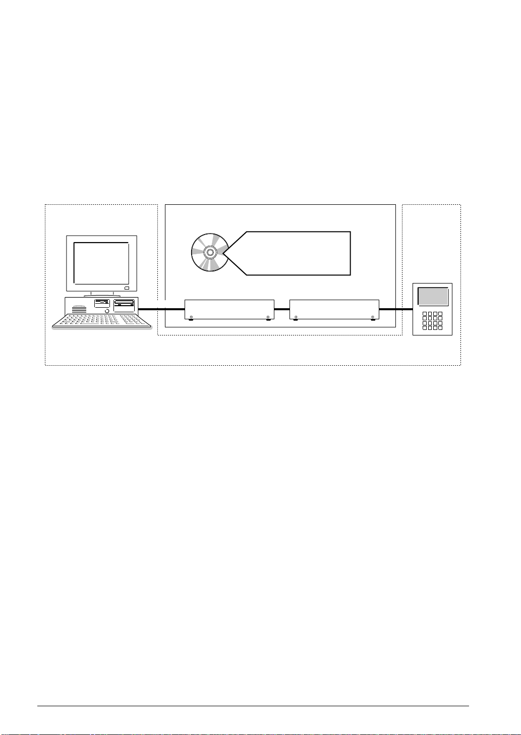
2 DEVELOPMENTAL ENVIRONMENT
The software product of the development support tool S5U1C62xxxD operates on the following host
systems:
• IBM PC/AT (at least PC-DOS Ver. 2.0)
When developing the S1C62XXX, the above-mentioned host computer, editor, P-ROM writer, printer, etc.
must be prepared by the user in addition to the development tool which is normally supported by Seiko
Epson.
Host computer
(IBM PC/AT)
PC-DOS
Editor
RS-232C
• P-ROM writer
• Printer
Note The S5U1C62xxxD system requires a host computer with a RAM capacity of about 140K bytes.
Since the ICE (S5U1C62000H) is connected to the host computer with a RS-232C serial interface,
adapter board for asynchronous communication will be required depending on the host computer
used.
S5U1C62000A
S1C62xxx Development Tool
Software tools
S5U1C62xxxD
DMS6200 SOG62xx
ASM62xx ICS62xx
MLA628x MDC62xx
FOG62xx
Hardware tools
ICE Evaluation Board
S5U1C62000H
To be prepared by the user
Fig. 2.1 System configuration
S5U1C62xxxE
Target board
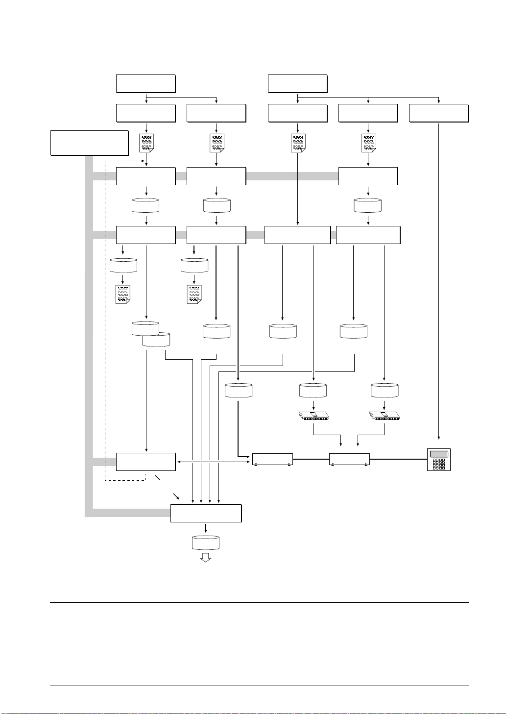
3 DEVELOPMENT FLOW
Figure 3.1 shows the development flow through the S5U1C62xxxD.
Concerning file names
All the input-output file name for the each development support tool commonly use "C2XXYYY". In
principle each file should be produced in this manner. Seiko Epson will designate the "YYY" for each
customer.
I-2 EPSON S1C62 FAMILY
DEVELOPMENT TOOL REFERENCE MANUAL
Page 13
INTRODUCTION
*4, *5
Development support tool
selection on menu of
Development Tool
Management System DMS6200
C2XXYYY
.PRN
Assembly list Melody
Determination of
software specifications
*2, *3, *4 *4, *5*4, *5 *4, *5 *1, *6
Flow chart generation
and coding
Coding
sheet
Source file generation
by using editor
Program
C2XXYYY
.DAT
source file
Cross Assembler
ASM62XX execution
Object file
C2XXYYYL
.HEX
C2XXYYYH
.HEX
*1, *2 *1
Melody generation
and coding
Source file generation
by using editor
C28XYYY
.MDT
Melody Assembler
MLA628X execution
C28XYYY
.MPR
assembly list
C28XYYYA
.DOC
Melody
document file
Coding
sheet
Melody
source file
Determination of
hardware specifications
Function option list
generation
Function
option
list
*4, *5*4, *5 *4, *5*4, *5
Function Option Generator
FOG62XX execution
C2XXYYYF
.DOC
Function option
document file
Segment option list
generation
Segment
option
list
Source file generation
by using editor
Segment option
C2XXYYY
.SEG
source file
Segment Option Generator
SOG62XX execution
C2XXYYYS
.DOC
Segment option
document file
Creation of
target board
C2XXYYYF
.HEX
Function
option
HEX file
Function
option ROM
(one)
S5U1C62xxxE
C2XXYYYS
.HEX
ICS62XX
*4, *5
Debugging
completion
Debugging with
ICE Control Software
C28XYYYA
.HEX
Melody
HEX file
ICE Evaluation Board
S5U1C62000H
*4, *7 *6
*4, *5
Mask Data Checker
MDC62XX execution
Note The melody and segment option flow are
C62XXYYY
.PAn
SEIKO EPSON
File for
submission
only valid in models possessing those
functions.
Fig. 3.1 S5U1C62xxxD development flow
☞ Reference manual
*1 S1C62xxx Technical Manual (Hardware) *5 S5U1C62xxxD Manual
*2 S1C62xxx Technical Manual (Software) *6 S5U1C62xxxE Manual
*3 S1C6200/6200A Core CPU Manual *7 S5U1C62000H Manual
*4 S1C62 Family Development Tool Reference Manual (this manual)
Segment
option
HEX file
Segment
option ROM
(two)
Target board
S1C62 FAMILY EPSON I-3
DEVELOPMENT TOOL REFERENCE MANUAL
Page 14

INTRODUCTION
4 INSTALLATION
The S5U1C62xxxD tools are included on the CD-ROM of the S5U1C62000A (S1C60/62 Family Assembler
Package), and they can be installed in your hard disk using the installer (Setup.exe) on the CD-ROM.
Refer to the "S5U1C62000A Manual" for how to install the S5U1C62xxxD tools.
Note The DMS6200 configures a menu from files that are located in the current directory. Therefore, do
not move the development tools from the directory in which the DMS6200 exists.
To invoke an editor (DOS version) or other programs from the DMS6200, copy those executable
files to the directory in which the DMS6200 exists.
I-4 EPSON S1C62 FAMILY
DEVELOPMENT TOOL REFERENCE MANUAL
Page 15

INTRODUCTION
5 DIFFERENCES FROM MODEL TO
MODEL AND PRECA UTIONS
There may be some models in which the following two types software tools contained in the
S5U1C62xxxD are not included.
(1) Segment Option Generator SOG62XX
This is not included in the software tools of models in which the segment option has not been set.
(2) Melody Assembler MLA628X
This is not included in the software tools for the models (Other than S1C62N8X) that do not have the
melody function.
Please be aware of the following points in setting the host system.
(1) The S5U1C62xxxD system requires a host computer with a RAM capacity of about 140K bytes.
(2) Since the ICE is connected to the host computer with a RS-232C serial interface, adapter board for
asynchronous communication will be required depending on the host computer used.
(3) In order for the MDC62XX to handle numerous files, set the number of files described in the
CONFIG.SYS to 10 or more (e.g., FILES = 20).
S1C62 FAMILY EPSON I-5
DEVELOPMENT TOOL REFERENCE MANUAL
Page 16

INTRODUCTION
6 TROUBLESHOOTING
Tool
ICE
S5U1C62000H
SOG62XX
Problem
Nothing appears on the screen, or
nothing works, after activation.
The ICE fuse cut immediately after
activation.
<ILLEGAL VERSION ICE6200>
appears on the screen immediately after
activation.
<ILLEGAL VERSION PARAMETER
FILE> appears on the screen immediately after activation.
Immediate values A (10) and B (11)
cannot be entered correctly with the A
command.
<UNUSED AREA> is displayed by the
SD command.
You can not do a real-time run in
break-trace mode.
Output from the evaluation board is
impossible when data is written to the I/
O memory for Buzzer and Fout output
with the ICE command.
An R error occurs although the address
is correctly set in the segment source
file.
Remedy measures
Check the following and remedy if necessary:
• Is the RS-232C cable connected correctly?
• Is the RS-232C driver installed?
• Is MODE.COM on the disk?
• Is the execution file correct?
PC-DOS ICS62XXW.EXE
• Is the DOS version correct?
PC-DOS Ver. 2.1 or later
• Is the DIP switches that set the baud rate of the main ICE
unit set correctly?
• Is the fuse of the ICE cut off?
Check the following and remedy if necessary:
• Are connectors F1 and F5 connected to the evaluation
board correctly?
• Is the target board power short-circuiting?
The wrong version of ICE is being used. Use the latest
version.
The wrong version of ICS62XXP.PAR is being used. Use
the latest version.
The A and B registers are reserved for the entry of A and B.
Write 0A and 0B when entering A (10) and B (11).
Example: LD A, B Data in the B register is
loaded into the A register.
LD B, 0A Immediate value A is loaded
into the B register.
This massage is output when the address following one in
which data is written is unused. It does not indicates
problem. Data is correctly set in areas other than the readonly area.
Since the CPU stops temporarily when breaking conditions
are met, executing in a real-time is not performed.
Output is possible only in the real-time run mode.
Check the following and remedy if necessary:
• Does the address symbol use capital letters?
• Are the output ports set for every two terminals?
I-6 EPSON S1C62 FAMILY
DEVELOPMENT TOOL REFERENCE MANUAL
Page 17

INTRODUCTION
Tool
ASM62XX
MDC62XX
MLA628X
Evaluation
board
S5U1C62xxxE
Problem
An R error occurs although the final
page is passed.
Activation is impossible.
No melody is output.
The evaluation board does not work
when it is used independently.
Target segment does not light.
Remedy measures
The cross assembler is designed to output "R error" every
time the page is changed. Use a pseudo-instruction to set the
memory, such as ORG or PAGE, to change the page. See
"Memory setting pseudo-instructions" in the cross assembler manual.
Check the following and remedy if necessary:
• Is the number of files set at ten or more in OS environment file CONFIG.SYS?
Check the following and remedy if necessary:
•
Has the OPTLD command of the ICE been executed? (When
the ICE is connected to the
evaluation board
)
• Is the MELODY ROM installed? (When the evaluation
board is used independently)
• Is the attack bit of the melody data set to "1"?
Check the following and remedy if necessary:
• Has the EPROM for F.HEX and S.HEX been replaced by
the EPROM for the target?
• Is the EPROM for F.HEX and S.HEX installed correctly?
• Is the appropriate voltage being supplied? (5V DC, 3 A,
or more)
• Are the program ROMs (H and L) installed correctly?
• Is data written from address 4000H? (When the 27C256
is used as the program ROM)
• Is the EN/DIS switch on the evaluation board set to EN?
Check the following and remedy if necessary:
• Is an EPROM with an access time of 170 ns or less being
used for S.HEX.
• Has the VADJ VR inside the evaluation board top cover
been turned to a lower setting?
S1C62 FAMILY EPSON I-7
DEVELOPMENT TOOL REFERENCE MANUAL
Page 18

Page 19

II
DEVELOPMENT TOOL MANAGEMENT SYSTEM
DMS6200
This part mainly explains how to operate the Development Tool Management System DMS6200.
Page 20

Page 21

DEVELOPMENT TOOL MANAGEMENT SYSTEM DMS6200
DEVELOPMENT TOOL MANAGEMENT SYSTEM
Contents
1 DIFFERENCES DEPENDING ON THE MODEL __________________ II-1
2 DMS6200 OUTLINE ___________________________________________ II-1
3 DMS6200 OPERATION PROCEDURE ___________________________ II-2
S1C62 FAMILY EPSON II-i
DEVELOPMENT TOOL REFERENCE MANUAL
Page 22

Page 23
DEVELOPMENT TOOL MANAGEMENT SYSTEM DMS6200
1 DIFFERENCES DEPENDING
ON THE MODEL
The DMS6200 is a software tool that is common to the all models of the S1C62 Family and there is
no difference in operating procedure. However, the content of such things as the menu screen may vary
due to differences in the configuration of the software for each model and differences in the directory
content in the DMS6200.
The below two types that are included in the explanation and display screen examples may not be present
in certain models.
(1) The SOG62XX and C2XXYYYS.* are only available in models offering the segment option.
(2) The MLA628X, C28XYYY.M* and C28XYYYA.* are only available in models offering the melody
function.
When models that do not have the above functions are used, disregard the respective program names and
file names indicated in the manual.
Refer to the "S5U1C62xxxD Manual" for the software tools included in the S5U1C62xxxD.
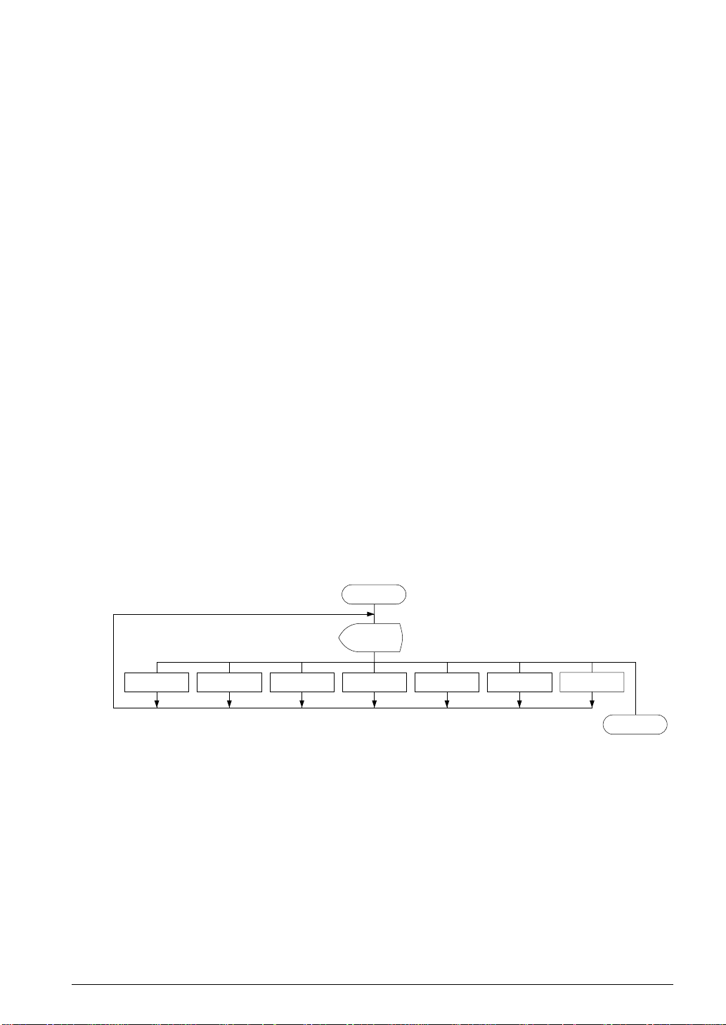
2 DMS6200 OUTLINE
The DMS6200 (Development Tool Management System) is a software which selects the
S5U1C62xxxD software development support tool and the program such as an editor in menu form and
starts it.
In this way the various software frequently executed during debugging can be effectively activated.
Figure 2.1 shows the DMS6200 execution flow.
DMS6200
Menu
selections
ASM62XX SOG62XX Editor etc.
Fig. 2.1 DMS6200 execution flow
ICS62XXFOG62XXMLA628X MDC62XX
To DOS
S1C62 FAMILY EPSON II-1
DEVELOPMENT TOOL REFERENCE MANUAL
Page 24

DEVELOPMENT TOOL MANAGEMENT SYSTEM DMS6200
3 DMS6200 OPERATION PROCEDURE
Set the directory containing the respective software development support tools into the current
directory prior to activating the DMS6200.
Since the development support tools each require input files (e.g., source file), first create the input files
according to the support tool manuals and then perform the following operations:
(1) The following is entered on the current drive:
DMS6200
indicates the return key.
The title is then displayed. To return to DOS at this point, press ^C (CTRL + C).
Initial screen
*** E0C6200 Development tool Management System. --- Ver 1.0 ***
EEEEEEEEEE PPPPPPPP SSSSSSS OOOOOOOO NNN NNN
EEEEEEEEEE PPPPPPPPPP SSS SSSS OOO OOO NNNN NNN
EEE PPP PPP SSS SSS OOO OOO NNNNN NNN
EEE PPP PPP SSS OOO OOO NNNNNN NNN
EEEEEEEEEE PPPPPPPPPP SSSSSS OOO OOO NNN NNN NNN
EEEEEEEEEE PPPPPPPP SSSS OOO OOO NNN NNNNNN
EEE PPP SSS OOO OOO NNN NNNNN
EEE PPP SSS SSS OOO OOO NNN NNNN
EEEEEEEEEE PPP SSSS SSS OOO OOO NNN NNN
EEEEEEEEEE PPP SSSSSSS OOOOOOOO NNN NN
(C) Copyright 1991 SEIKO EPSON CORP.
STRIKE ANY KEY.
(2) Press any key and the following menu screen will be displayed. A list of all executable files having
"EXE", "COM" and "BAT" extensions will appear on this menu screen; if any execution file other than
S5U1C62xxxD were copied to the current drive for execution, it will differ from the displays shown
below.
Menu screen
DMS6200 Version 1.0 Copyright(C) SEIKO EPSON CORP. 1991.
1) ASM62XX .EXE
2) FOG62XX .EXE
3) ICS62XXB.BAT
4) ICS62XXW.EXE
5) MDC62XX .EXE
6) MLA628X .EXE
7) SOG62XX .EXE
Input Number ? [ ]
To return to DOS at this point, press the "ESC" key.
II-2 EPSON S1C62 FAMILY
DEVELOPMENT TOOL REFERENCE MANUAL
Page 25

DEVELOPMENT TOOL MANAGEMENT SYSTEM DMS6200
(3) Input the number of the development support tool you wish to start and then press the "RETURN" key.
Next, the screen for entering the source file will be displayed.
Input Number ? [1 ]
(4) The following sample screen is the screen which will be displayed when ASM62XX is selected.
Input the number of the source file.
Pressing the "ESC" key here will return the previous screen.
When the source file is selected by number, the edit line enclosed in [ ] will appear; enter the option
parameter if necessary. The "BS" key is valid on the edit line. Press the "RETURN" key when input is
completed.
Source file selection screen
DMS6200 Version 1.0 Copyright(C) SEIKO EPSON CORP. 1991.
1) C2XXYYY .DAT
2) C28XYYY .MDT
3) C28XYYY .MPR
4) C2XXYYY .PRN
5) C2XXYYY .SEG
6) C28XYYYA.DOC
7) C28XYYYA.HEX
8) C2XXYYYF.DOC
9) C2XXYYYF.HEX
10) C2XXYYYH.HEX
11) C2XXYYYL.HEX
12) C2XXYYYS.DOC
13) C2XXYYYS.HEX
14) C62XXYYY.PA0
Input Number ? [1 ]
Edit > [ASM62XX C2XXYYY ]
The above operation will activate the ASM62XX. (The MLA628X will also activate with the same
operation.)
When the source file is in another file or directory it will not be displayed in the menu. In such cases
you skip the number input using the return key and input the drive/directory and source file name in
the edit line.
When starting, press the "RETURN" key twice particularly for the support tools which do not require
source files (except the ASM62XX and the MLA628X).
Refer to the support manuals regarding operations after starting.
(5) When execution of the development support tool is completed, the following message will appear:
Input Any Key ...
Press any key and the first menu screen will be returned.
S1C62 FAMILY EPSON II-3
DEVELOPMENT TOOL REFERENCE MANUAL
Page 26

Page 27

III
CROSS ASSEMBLER
ASM62XX
This part mainly explains how to operate the
Cross Assembler ASM62XX for the S1C62
Family, and how to generate source files.
Page 28

Page 29

CROSS ASSEMBLER ASM62XX
CROSS ASSEMBLER ASM62XX
Contents
1 DIFFERENCES DEPENDING ON THE MODEL __________________ III-1
2 ASM62XX OUTLINE __________________________________________ III-2
2.1 Outline ................................................................................................................... III-2
2.2 ASM62XX Input/Output Files ................................................................................ III-2
3 ASM62XX OPERATION PROCEDURE __________________________ III-3
3.1 Starting ASM62XX ................................................................................................ III-3
3.2 Selecting Auto-Page-Set Function......................................................................... III-5
3.3 Generating a Cross-Reference Table .................................................................... III-5
4 SOURCE FILE FORMAT _____________________________________ III-6
4.1 Source File Name .................................................................................................. III-6
4.2 Statements .............................................................................................................. III-6
4.2.1 Label field .................................................................................................... III-6
4.2.2 Mnemonic field ............................................................................................ III-7
4.2.3 Operand field ............................................................................................... III-7
4.2.4 Comment field .............................................................................................. III-7
4.3 Index ...................................................................................................................... III-7
4.3.1 Label ............................................................................................................ III-7
4.3.2 Symbol ......................................................................................................... III-8
4.4 Constant and Operational Expression .................................................................. III-8
4.4.1 Numeric constant ......................................................................................... III-8
4.4.2 Character constant ...................................................................................... III-8
4.4.3 Operator ...................................................................................................... III-9
4.4.4 Location counter ......................................................................................... III-10
4.5 Pseudo-Instructions .............................................................................................. III-11
4.5.1 Data definition pseudo-instructions ........................................................... III-11
4.5.2 Memory setting pseudo-instructions........................................................... III-12
4.5.3 Assembler control pseudo-instructions ...................................................... III-15
4.6 Macro-Functions .................................................................................................. III-15
4.6.1 Macro-instructions ..................................................................................... III-15
4.6.2 Macro-definitions ....................................................................................... III-16
4.6.3 Macro-calls................................................................................................. III-17
5 ERROR MESSAGES__________________________________________ III-19
APPENDIX ASM62XX EXECUTION EXAMPLE __________________ III-20
1) Source file (C2XX0A0.DAT) ........................................................................... III-20
2) Running the assembler (display on the console) ............................................. III-21
3) Assembly listing file (C2XX0A0.PRN) ............................................................ III-22
4) Object files (C2XX0A0H.HEX, C2XX0A0L.HEX) .......................................... III-23
S1C62 FAMILY EPSON III-i
DEVELOPMENT TOOL REFERENCE MANUAL
Page 30

Page 31

CROSS ASSEMBLER ASM62XX
1 DIFFERENCES DEPENDING
ON THE MODEL
Since the memory capacity will vary with each model of the S1C62 Family you must pay attention
to the following points when preparing a program.
The limiting items for each model are indicated in the "S5U1C62xxxD Manual".
■ ROM area
The ROM capacity will vary depending on the model.
The number of banks (16 pages/bank) and the number of pages (256 steps/page) are determined by
this ROM capacity and the memory setting pseudo-instruction and the "PSET" instruction is limited to
within its range.
Valid specification range
ORG pseudo-instruction: 0000H–ROM final step
PAGE pseudo-instruction: 00H–number of page - 1
BANK pseudo-instruction: 1 bank configuration model → 0H only
2 bank configuration model → 0H and 1H
PSET instruction: 00H–number of page - 1
When a specification beyond this valid specification range is made to the ASM62XX an error is pro-
duced.
■ RAM area
The RAM capacity varies depending on the model.
The number of pages (256 words/page) is determined according to the RAM capacity. Also, the
undefined area includes from the 0 address to the final RAM address.
When an undefined address is set in the index register, memory access to it becomes invalid, but be
careful that no errors develop in the ASM62XX.
■ Undefined code
In the S1C62 Family, the instruction set is not different from model to model. However, you may not be
able to use instructions such as the SLP instruction and those that access the page section (XP and YP)
of the index register depending on the RAM content.
S1C62 FAMILY EPSON III-1
DEVELOPMENT TOOL REFERENCE MANUAL
Page 32

CROSS ASSEMBLER ASM62XX
2 ASM62XX OUTLINE
2.1 Outline
The ASM62XX cross assembler (the ASM62XX in this manual) is an assembler program for generating the
machine code used by the S1C62XXX 4-bit, single-chip microcomputers. It can be used under PC-DOS.
The Cross Assembler ASM62XX will assemble the
program source files which have been input by the
user's editor and will generate an object file in IntelHex format and assembly list file.
In this assembler, program modularization has been
made possible through macro definition functions and
programming independent of the ROM page structure
has been made possible through the auto page set
function. In addition, consideration has also been given
to precise error checks for program capacity (ROM
capacity) overflows, undefined codes and the like, and
for debugging of such things as label tables for assembly list files and cross reference table supplements.
The program name of the assembler is ASM62XX.EXE.
Figure 2.1.1 shows the ASM62XX execution flow.
Error
message
Error
message
A>EDLIN C2XXYYY.DAT
Create the source file
C2XXYYY
.DAT
A>ASM62XX C2XXYYY
Execute the cross assembler
C2XXYYY
.PRN
Assembly
listing file
C2XXYYYL
.HEX
Object file
C2XXYYYH
Fig. 2.1.1 ASM62XX execution flow
.HEX
2.2 ASM62XX Input/Output Files
ASM62XX reads a source file, assembles it, and outputs object files and an assembly listing file.
■ Source file (C2XXYYY.DAT)
This is a source program file produced using an editor such as EDLIN. The file name format is
C2XXYYY, and the file name must not exceed seven characters in length. Character string YYY should
be determined by referencing the device name specified by Seiko Epson. The file extension must be
added ".DAT".
■ Object file (C2XXYYYH.HEX, C2XXYYYL.HEX)
This is an assembled program file in Intel hex format. Because the machine code of the S1C62XXX is 12bit, the high-order bytes (bits 9 to 12 suffixed by high-order bits 0000B) are output to file
C2XXYYYH.HEX, and the low-order bytes (bits 8 to 1) are output to file C2XXYYYL.HEX.
■ Assembly listing file (C2XXYYY.PRN)
This is a program listing file generated by adding an operation codes and error messages (if any errors
have occurred) to respective source program statements. A cross-reference table is generated at the end
of the file, depending on the label table and options. The file name is C2XXYYY.PRN.
See the Appendix for the contents of each file.
III-2 EPSON S1C62 FAMILY
DEVELOPMENT TOOL REFERENCE MANUAL
Page 33

CROSS ASSEMBLER ASM62XX
3 ASM62XX OPERATION PROCEDURE
This section explains how to operate ASM62XX.
3.1 Starting ASM62XX
When starting ASM62XX, enter the following at DOS command level (when a prompt such as A> is being
displayed):
ASM62XX _ [drive-name:] source-file-name [.shp] _ [-N]
When starting ASM62XX through the DMS6200, selects the "ASM62XX.EXE" and source file in the menu
screen, and input options necessary.
■ Drive name
If the source file is not on the same disk as ASM62XX.EXE, specify a disk drive mounted the floppy disk
storing the source file before input the source file name. If the source file is on the same disk as
ASM62XX.EXE, it does not need to specify the disk drive.
■ Source file name
This is the name of the source file to be entered for ASM62XX. The source file name must not exceed
seven characters in length. File extension .DAT must not be entered.
_ indicates a blank.
A parameter enclosed by [ ]
can be omitted.
indicates the return key.
■ .shp
Characters s, h, and p are options for specifying the file I/O drives, and can be omitted.
s: Specifies the drive from which the source file is to be input. A character from A to P can be
specified. If @ is specified, the source file in the current drive (directory) is input. Even if a drive
name is prefixed to the source file name, this option is effective.
h: Specifies the drive to which the object file (HEX) is to be output. A character from A to P can be
specified. If @ is specified, the object file is output to the current drive (directory). If Z is
specified, only assembly is executed; the object file is not generated.
p: Specifies the drive to which the assembly listing file is to be output. A character from A to P can
be specified. If @ is specified, the object file is output to the current drive (directory). If X is
specified, a listing containing error messages is output to the console. If Z is specified, the
assembly listing file is not generated.
Characters s, h, p must all be specified; only one or two of them is not sufficient.
■ -N option
The code (FFH) in the undefined area of program memory is not created.
Note The program data to be provided does not use the "-N" option. The FFH data should be inserted into
the undefined program area.
S1C62 FAMILY EPSON III-3
DEVELOPMENT TOOL REFERENCE MANUAL
Page 34

CROSS ASSEMBLER ASM62XX
Example 1: Basic assembly example
A>ASM62XX C2XXYYY
A>ASM62XX B:C2XXYYY
A>ASM62XX C2XXYYY.BBZ
Example 2: -N option use
A>ASM62XX C2XXYYY -N
The source file "C2XXYYY.DAT" is input from drive A, and the
object files "C2XXYYYH.HEX" and "C2XXYYYL.HEX" and
the assembly listing file "C2XXYYY.PRN" are output to drive A.
The source file "C2XXYYY.DAT" is input from drive B, and the
object files "C2XXYYYH.HEX" and "C2XXYYYL.HEX" and
the assembly listing file "C2XXYYY.PRN" are output to drive B.
The source file "C2XXYYY.DAT" is input from drive B, and the
object files "C2XXYYYH.HEX" and "C2XXYYYL.HEX" are
output to drive B. The assembly listing file is not generated.
No undefined program area is generated in the created object files
(C2XXYYYH.HEX, C2XXYYYL.HEX).
Refer to APPENDIX, "ASM62XX EXECUTION EXAMPLE".
A>ASM62XX C2XXYYY
When ASM62XX is started, the following start-up message is displayed.
Example: When assembling C2XX0A0.DAT
A>ASM62XX C2XX0A0
*** E0C62XX CROSS ASSEMBLER. --- Ver 2.00 ***
EEEEEEEEEE PPPPPPPP SSSSSSS OOOOOOOO NNN NNN
EEEEEEEEEE PPPPPPPPPP SSS SSSS OOO OOO NNNN NNN
EEE PPP PPP SSS SSS OOO OOO NNNNN NNN
EEE PPP PPP SSS OOO OOO NNNNNN NNN
EEEEEEEEEE PPPPPPPPPP SSSSSS OOO OOO NNN NNN NNN
EEEEEEEEEE PPPPPPPP SSSS OOO OOO NNN NNNNNN
EEE PPP SSS OOO OOO NNN NNNNN
EEE PPP SSS SSS OOO OOO NNN NNNN
EEEEEEEEEE PPP SSSS SSS OOO OOO NNN NNN
EEEEEEEEEE PPP SSSSSSS OOOOOOOO NNN NN
(C) COPYRIGHT 1991 SEIKO EPSON CORP.
SOURCE FILE NAME IS " C2XXYYY.DAT "
THIS SOFTWARE MAKES NEXT FILES.
C2XXYYYH.HEX ... HIGH BYTE OBJECT FILE.
C2XXYYYL.HEX ... LOW BYTE OBJECT FILE.
C2XXYYY .PRN ... ASSEMBLY LIST FILE.
In this case, FFH data is inserted into the undefined program area
of the object files.
III-4 EPSON S1C62 FAMILY
DEVELOPMENT TOOL REFERENCE MANUAL
Page 35

CROSS ASSEMBLER ASM62XX
3.2 Selecting Auto-P age-Set Function
After the start-up message, the following message is displayed, prompting the user to select the auto-pageset function.
DO YOU NEED AUTO PAGE SET?(Y/N)
Press the "Y" key if selecting the auto-page-set function, or the "N" key if not selecting it. At this stage, the
user can also return to the DOS command level by entering "CTRL" + "C" key.
■ Auto-page-set function
When the program branches to another page through a branch instruction such as JP, the branchdestination page must be set using the PSET instruction before executing the branch instruction.
The auto-page-set function automatically inserts this PSET instruction. It checks whether the branch
instruction page is the same as the branch-destination one. If the page is different, the function inserts
the "PSET" instruction. If the page is the same, the function performs no operation.
Therefore, do not select the auto-page-set function if "PSET" instructions have been correctly included
in the source file.
Note When auto-page-set is selected, there are restricted items related to source programming. See
"4.3.1 Label".
3.3 Generating a Cross-Reference Table
After the auto-page-set function has been selected, the following message is output, prompting the user to
select cross-reference table generation.
DO YOU NEED CROSS REFERENCE TABLE?(Y/N)
Press the "Y" key if generating the cross-reference table, or the "N" key if not generating it. At this stage,
the user can also return to DOS command level by entering "CTRL" + "C" key.
Note If the assembly listing file output destination (p option) is specified as Z (listing not generated) at the
start of ASM62XX, the above message is not output and the cross-reference table is not generated.
■ Cross-reference table
The cross-reference table lists the symbols and their locations in the source file, and is output at the end
of the assembly listing file in the following format:
CROSS REFERENCE TABLE PAGE X- 1
LABEL1 4# 29 36 ....
LABEL2 15# 40
: : :
Symbol Number of the program statement
(# indicates the number of the statement at which the symbol was defined)
This table should be referenced during debugging. An error such as duplicate definition of a symbol can
be easily detected.
S1C62 FAMILY EPSON III-5
DEVELOPMENT TOOL REFERENCE MANUAL
Page 36

CROSS ASSEMBLER ASM62XX
4 SOURCE FILE FORMAT
The source file contains the source program consisting of S1C62XXX instructions (mnemonics) and
pseudo-instructions, and is produced using an editor such as EDLIN.
Refer to the "S1C6200/6200A Core CPU Manual" and the "S1C6xxx Technical Manual (Software)" for
instruction sets.
4.1 Source File Name
A desired file name not exceeding seven characters in length can be assigned to each source file. The
format must be as follows:
C2XXYYY.DAT
"YYY" of the "C2XXYYY.DAT" is an alphanumeric character string of up to three characters, and should be
determined by referencing the device name specified by Seiko Epson. The file extension must be ".DAT".
4.2 Statements
Each source program statement must be written using the following format.
Basic format: <Index>[:] <Instruction> <Expression> <; comment>
Example: ON EQU 1
START: JP INIT ;To init.
Label Mnemonic Operand Comment
field field field field
A statement consists of four fields: label, mnemonic, operand, and comment. Up to 132 characters can be
used for one statement. Fields must be delimited by one or more blanks or tabs.
The label and comment fields are optional. Blank lines consisting only of a carriage return (CR) code are
also allowed.
Although each statement and field (excluding the label field) can begin at any desired column. The
program becomes easier to understand if the heads of corresponding fields are aligned.
ORG 100H
Label field
4.2.1
The label field can contain a label for referencing the memory address, a symbol that defines a constant, or
a macro name. This field can be omitted if the statement name is not required. The label field must begin
at column 1 and satisfy the following conditions.
• The length must not exceed 14 characters.
• The same name as a mnemonic or register name must not be used.
• The following alphanumeric characters can be used, but the first character must not be a digit:
A to Z, a to z, 0 to 9, _ , ?
• The uppercase and lowercase forms of a letter are equivalent.
• ??nnnn (n is a digit) cannot be used as a name.
A colon ":" can be used as a delimiter between a label field and the mnemonic field. If a colon is used,
neither blanks nor tabs need to be written subsequently.
Statements consisting of only a label field are also allowed.
III-6 EPSON S1C62 FAMILY
DEVELOPMENT TOOL REFERENCE MANUAL
Page 37

CROSS ASSEMBLER ASM62XX
4.2.2 Mnemonic field
The mnemonic field is used for an instruction mnemonic or a pseudo-instruction.
Operand field
4.2.3
The operand field is used for the operands of the instruction. The form of each operand and the number of
operands depend on the kind of instruction. The form of expressions specifying values must be one of the
following:
• A numeric constant, a character constant, or a symbol that defines a constant
• A label indicating a memory address
• An operational expression for obtaining the specified value
If the operand consists of two or more expressions, the expressions must be separated by commas ",".
Comment field
4.2.4
The comment field is used for comment data such as program headers and descriptions of processing. The
contents of this field do not affect assembly or the object files generated by assembly.
The part of the statement from a semicolon ";" to the CR code at the end of the statement is considered to be
the comment field. Statements consisting of only a comment field are also allowed. When a comment
spans multiple lines, a semicolon must be written at the beginning of each line.
4.3 Index
ASM62XX allows values to be referenced by their indexes.
Refer to Section 4.2.1, "Label field", for the restrictions on index descriptions.
Label
4.3.1
A label is an index for referencing a location in the program, and can be used as an operand that specifies a
memory address as immediate data in an instruction. For example, a label can be used as the operand of
an instruction such as JP by writing the label in the branch-destination statement.
The name written in the label field of an EQU or SET instruction is considered to be a symbol, not a label.
Example:
:
JP NZ,LABEL1
:
:
LABEL1: LD A,0
A label can be assigned to any statement, but the label assigned to the following pseudo-instructions is
ignored:
ORG, BANK, PAGE, SECTION, END, LABEL, ENDM
Note When selecting the auto-page-set function (see Section 3.2), a statement consisting of only a label
must be written immediately before the JP or CALL instructions.
Example:
PGSET:
JP LABEL
S1C62 FAMILY EPSON III-7
DEVELOPMENT TOOL REFERENCE MANUAL
Page 38

CROSS ASSEMBLER ASM62XX
4.3.2 Symbol
A symbol is an index that indicates a numeric or character constant, and must be defined before its value is
referenced (usually at the beginning of the program). The defined symbol can be used as the operand that
specifies immediate data in an instruction.
Example:
ON EQU 1 (See Section 4.5 for EQU.)
OFF EQU 0
:
LD A,ON ; = LD A,1
:
LD A,OFF ; = LD A,0
:
4.4 Constant and Operational Expression
This section explains the immediate data description formats.
Numeric constant
4.4.1
A numeric constant is processed as a 13-bit value by ASM62XX. If a numeric constant greater than 13 bits
is written, bit 13 and subsequent high-order bits are ignored.
Note that the number of actual significant bits depends on the operand of each instruction. If the value of a
constant is greater than the value that can be accommodated by the actual number of significant digits, an
error occurs.
Example:
ABC EQU 0FFFFH → ABC is defined as 1FFFH.
LD A,65535 → An error occurs because it exceeds the significant digit
count (4 bits).
The default radix is decimal. The radix description formats are as follows:
Binary numeral: A numeral suffixed with B, such as 1010B (=10) or 01100100B (=100).
Octal numeral: A numeral suffixed with O or Q, such as 012O (=10) or 144Q (=100).
Decimal numeral: A numeral alone or a numeral suffixed with D, such as 10 or 100D (=100).
Hexadecimal numeral: A numeral suffixed with H, such as 0AH (=10) or 64H (=100).
If the value begins with a letter from A to F, it must be prefixed with 0 to distinguish
it from a name.
Character constant
4.4.2
A character constant is one or two ASCII characters enclosed by apostrophes (' '). A single ASCII character
is processed as eight-bit data. If two or more ASCII characters are written, only the last two characters are
significant as 13-bit data.
Examples:
'A' (=41H), 'BC' (=0243H), 'PQ' (=1051H), 'DEFGH' → 'GH' (=0748H; DEF is ignored.)
The apostrophe itself cannot be processed as a character constant, so it must be written as a numeric
constant, such as 27H or 39.
III-8 EPSON S1C62 FAMILY
DEVELOPMENT TOOL REFERENCE MANUAL
Page 39

CROSS ASSEMBLER ASM62XX
4.4.3 Operator
When specifying a value for an item such as an operand, an operational expression can be written instead
of a constant, and its result can be used as the value.
Labels and symbols as well as constants can be used as terms in expressions. These values are processed as
13-bit data (bit 14 and subsequent high-order bits are ignored); the operation result also consists of 13 bits.
If the result exceeds the number of significant digits of the instruction operand, an error occurs.
There are three types of operator—arithmetic, logical, and relational—as listed below (a and b represent
terms, and _ represents one or more blanks).
■ Arithmetic operators
There are 11 arithmetic operators including the ones for addition, subtraction, multiplication, division,
bit shifting, and bit separation.
+a Monadic positive (indicates the subsequent value is positive)
-a Monadic negative (indicates the subsequent value is negative)
a+b Addition (unsigned)
a-b Subtraction (unsigned)
a*b Multiplication (unsigned)
a/b Division (unsigned)
a_MOD_b Remainder of a/b
a_SHL_b Shifts a b bits to the left. ←[b7<<<<<<b1]←0
Example:
a_SHR_b Shifts a b bits to the right. 0→[b7>>>>>>b0]→
Example:
HIGH_a Separates the high-order eight bits from a (13 bits).
Example:
LOW_a Separates the low-order eight bits from a (13 bits).
Example: LOW 1234H → 34H
00000011B SHL 2 → 00001100B
11000011B SHR 2 → 00110000B
HIGH 1234H → 12H
■ Logical operators
There are four logical operators as listed below. The logical operator returns the result of logical
operation on the specified terms.
a_AND_b Logical product
Example:
a_OR_b Logical sum
Example: 00001111B OR 11110000B → 11111111B
a_XOR_b Exclusive logical sum
Example:
NOT_a Logical negation
Example:
S1C62 FAMILY EPSON III-9
DEVELOPMENT TOOL REFERENCE MANUAL
00001111B AND 00000011B → 00000011B
00001111B XOR 00000011B → 00001100B
NOT 00001111B → 11110000B
Page 40

CROSS ASSEMBLER ASM62XX
■ Relational operators
A logical operator compares two terms; if the relationship between the terms is as the operator
specifies, 1FFFH (true) is returned; if not, 0 (false) is returned.
a_EQ_b True when a is equal to b
a_NE_b True when a is not equal to b
a_LT_b True when a is less than b
a_LE_b True when a is less than or equal to b
a_GT_b True when a is greater than b
a_GE_b True when a is greater than or equal to b
Be sure to insert one or more blanks for symbol "_" between terms. All operators must be entered in
uppercase letters.
An expression can contain one or more operators and pairs of parenthesis. In this case, operators are
basically evaluated from left to right. However, an operation stipulated by an operator with higher priority
or by parentheses is executed earlier. Every left parenthesis must have a corresponding right parenthesis.
The following table shows the priority of operators.
Operator Priority
) Low
OR, XOR :
AND
EQ, NE, LT, LE, GT, GE
+ (addition), - (subtraction)
*, /, MOD, SHL, SHR
(
HIGH, LOW, NOT :
- (monadic negative), + (monadic positive) High
Examples: Operational expressions (ABC = 1, BCD = 3)
LD A,BCD*(ABC+1) ;A-register <- 6
LD A,ABC LT BCD ;A-register <- 0FH (1111B)
OR B,ABC SHL BCD ;Set bit 3 in B-register
;(=OR B,1000B)
AND B,ABC SHL BCD XOR 0FH
;Reset bit 3 in B-register
;(=AND B,0111B)
4.4.4 Location counter
The start address of each instruction code is set in the location counter when a statement is assembled. A
label or $ can be used when referencing the location counter value in a program.
■ Location counter
The location counter consists of 13 bits: one bit for the bank field, four bits for the page counter field,
and eight bits for the step counter field.
Bank Page counter Step counter
Bit 1211109876543210
Contents Bank Page address Step address
BNK PCP PCS
Example: Location counter
(BNK) (PCP) (PCS)
0 1 02 JP $+3
The location counter indicates the start address of the JP instruction, and the PCS value (02) is assigned to $.
Consequently, the statement is assembled as "JP 5", and the program sequence jumps to the location three
steps before (PCS=05) when it is executed.
III-10 EPSON S1C62 FAMILY
DEVELOPMENT TOOL REFERENCE MANUAL
Page 41

CROSS ASSEMBLER ASM62XX
4.5 Pseudo-Instructions
There are four types of pseudo-instruction: data definition, memory setting, assembler control, and macro.
These pseudo-instructions as well as operational expressions can be used to govern assembly, and are not
executed in the developed program.
In the subsequent explanations, the items enclosed by < > in the pseudo-instruction format must be written
in the statement (do not write the < > characters themselves). Symbol _ represents one or more blanks or
tabs. One or more symbols and constants or an operational expression can be used in <expression>. See
Section 4.6 for macro functions.
Data definition pseudo-instructions
4.5.1
There are three data definition pseudo-instructions: EQU, SET, and DW. The EQU and SET pseudoinstructions each define a symbol, and the DW pseudo-instruction presets data in program memory.
■ EQU (Equate)
<Symbol>_EQU_<Expression> To define a symbol
The EQU pseudo-instruction defines <symbol> (written in the label field) as having the value of
<expression> (written in the operand field).
If a value greater than 13 bits is specified in <expression>, bit 14 and subsequent high-order bits are
ignored.
This definition must be made before the symbol is referenced in the program. A U-error occurs if an
attempt is made to reference a symbol that has not been defined.
The same symbol cannot be defined more than once. A P-error occurs if an attempt is made to define a
symbol that has already been defined.
Examples:
ZERO EQU 30H
ONE EQU ZERO+1
ONE EQU 31H ← P-error because ONE has been defined more than twice
FOUR EQU TWO*2 ← U-error because TWO has not been defined
■ SET
<Symbol>_SET_<Expression> To define a symbol
Like EQU, the SET pseudo-instruction defines the value of <symbol> as being <expression>. The SET
pseudo-instruction allows a symbol to be redefined.
Examples:
ZERO EQU 30H
BIT SET 1
:
BIT SET 2 ← Redefinition possible
:
BIT SET BIT SHL 1 ← Previously-defined items can be referenced
S1C62 FAMILY EPSON III-11
DEVELOPMENT TOOL REFERENCE MANUAL
Page 42

CROSS ASSEMBLER ASM62XX
■ DW (Define Word)
<Label>_DW_<Expression> To preset data
The DW pseudo-instruction assigns the value of <expression> (the low-order 12 bits when the value is
greater than 12 bits) to the current memory location, indicated by the location counter.
Examples:
Location counter
(BNK) (PCP) (PCS)
0 2 0A TABLE DW 141H ; = RETD 'A'
0 2 0B DW 142H ; = RETD 'B'
0 2 0C DW 143H ; = RETD 'C'
:
<label> can be omitted.
Memory setting pseudo-instructions
4.5.2
The program memory mounted at the S1C62XXX is divided into 256-step pages. Memory management
(including the setting of the program location and page boundaries) during program generation must be
controlled by the source program.
The memory setting pseudo-instructions are used to specify memory management. The assembler sets the
location counter according to these pseudo-instructions.
If a memory area that has already been used is specified or a statement that exceeds the page is used
without specifying that the statement is to exceed the page, the assembler displays an exclamation mark "!",
indicating a warning, and ignores all subsequent statements until the next correct statement. This should
be taken into account.
When using the auto-page-set function, the space for insertion of the "PSET" pseudo-instruction must be
allocated in each page.
■ ORG (Origin)
ORG_<Expression> To set the location counter
The ORG pseudo-instruction sets the location counter to the value of <expression>.
If the ORG pseudo-instruction is not written at the beginning of the program, the location counter is set
to 0 (BNK=0, PCP=0, PCS=0) and assembly is started.
The ORG pseudo-instruction can be used at multiple locations in the program. However, it cannot be
used to set the location to a value before the current location. If this is attempted, an exclamation mark
"!", indicating a warning, is displayed, and all subsequent statements until the next correct statement are
ignored.
A label can be written before the ORG statement, but it cannot be referenced because it is not cataloged
in the label table. In this case, write the label in the statement following the ORG pseudo-instruction.
Example:
ORG 0100H ; BNK=0, PCP=1, PCS=00H
START :
An R-error occurs if a value is specified exceeding the ROM capacity.
Note The upper limit of program memory depends on the model. (Refer to the "S5U1C62xxxD
Manual".)
III-12 EPSON S1C62 FAMILY
DEVELOPMENT TOOL REFERENCE MANUAL
Page 43

CROSS ASSEMBLER ASM62XX
■ BANK
BANK_<Expression> To set the bank (BNK)
The BANK pseudo-instruction sets the value of <expression> in the bank (BNK) field, and sets the page
counter (PCP) and step counter (PCS) to 00H.
The BANK pseudo-instruction can be written at multiple locations in the program. However, it cannot
be used to specify the current bank (excluding the specification in page 00, step 00) or a previous bank.
If it is used to specify the current bank or a previous bank, an exclamation mark "!", indicating a
warning, is displayed, and all subsequent statements until the next correct statement are ignored.
A label can be written before the BANK statement, but it cannot be referenced because it is not
cataloged in the label table. In this case, write the label in the statement after the BANK pseudoinstruction.
■ PAGE
PAGE_<Expression> To set the page counter (PCP)
The PAGE pseudo-instruction sets the value of <expression> in the page counter (PCP) and sets the
step counter (PCS) to 00H.
The PAGE pseudo-instruction can be written at multiple locations in the program. However, it cannot
be used to specify the current page (excluding the specification in step 00) or a previous page. If it is
used to specify the current page or a previous page, an exclamation mark "!", indicating a warning, is
displayed, and all subsequent statements until the next correct statement are ignored.
A label can be written before the PAGE statement, but it cannot be referenced because it is not
cataloged in the label table. In this case, write the label in the statement after the PAGE pseudoinstruction.
Example:
Location counter
(BNK) (PCP) (PCS)
::: ::
0 0 1AH LD X,0
0 0 1BH LD Y,0
::: ::
0 0 F0H JP xxx
0 2 00H SUB1: LD A,MX
PAGE 2
0 2 01H LD B,MY
Ineffective because a previous page
was specified
::: ::
PAGE 1
! SUB2: LD A,MX
! LD B,MY
Effective
::
PAGE 3
0 3 00H SUB3: LD A,0
0 3 01H LD B,1
::: ::
An R-error occurs if a value is specified that exceeds the last page.
Note The last page depends on the model. (Refer to the "S5U1C62xxxD Manual".)
S1C62 FAMILY EPSON III-13
DEVELOPMENT TOOL REFERENCE MANUAL
Page 44

CROSS ASSEMBLER ASM62XX
■ SECTION
SECTION To change the section
The SECTION pseudo-instruction sets the first address of the subsequent section in the location counter. Sections are 16-step areas starting from the beginning of the program memory.
(BNK) (PCP) (PCS)
0 1 00H
Section 1 16 steps
0 1 10H
Section 2
0 1 20H
::: : :
0 1 F0H
Section 16
0 2 00H
Section 17
0 2 20H
::: : :
0 3 F0H
Section 48
A SECTION pseudo-instruction written in the last section of the page not only clears the step counter
but also updates the page counter, so a new page need not be specified.
A label can be written before the SECTION pseudo-instruction, but it cannot be referenced because it is
not cataloged in the label table. In this case, write the label in the statement following the SECTION
pseudo-instruction.
Example:
Location counter
(BNK) (PCP) (PCS)
::: : :
0 1 09H JPBA
0 1 0AH LD X,0
0 1 0BH LD Y,0
0 1 0CH LD MX,4
SECTION
0 1 10H TABLE LD A,1
0 1 11H ADD A,1
::: : :
0 1 FAH RET
0 2 00H LOOP SCF
SECTION
0 2 01H ADD A,MY
::: : :
III-14 EPSON S1C62 FAMILY
DEVELOPMENT TOOL REFERENCE MANUAL
Page 45

CROSS ASSEMBLER ASM62XX
4.5.3 Assembler control pseudo-instructions
■ END
END To terminate assembly
The END statement terminates assembly. All statements following the END statement are ignored. Be
sure to write this statement at the end of the program. If it is missing, assembly may not terminate.
A label can be written before the END statement, but it cannot be referenced because it is not cataloged
in the label table.
4.6 Macro-Functions
When using the same statement block at multiple locations in a program, the statement block can be called
using a name defined beforehand. A statement block that has been so defined is called a macro.
Unlike a subroutine, the statement block is expanded at all locations where it is called, so the programmer
should consider the statement block size and frequency of use and determine whether a macro or a subroutine is more appropriate.
Macro-instructions
4.6.1
ASM62XX provides the macroinstructions listed below so that
branching between pages is possible
without specifying the destination
page using the PSET instruction.
Character string ps represents 13-bit
immediate data that indicates the
branch-destination address. A label
can be used for it.
Example:
Source file
:
JPM LABEL2
:
PAGE 2
LABEL2 LD A,0
:
Macro-
instruction
JPM ps
JPM C,ps
JPM NC,ps
JPM Z,ps
JPM NZ,ps
CALLM ps
Mnemonic
after expansion
PSET p
JP s
PSET p
JP C,s
PSWT p
JP NC,s
PSET p
JP Z,s
PSET p
JP NZ,s
PSET p
CALL s
1110987654321
1
1
1
0
0
0
1
1
1
1
0
0
1
1
1
1
0
0
1
1
1
1
0
1
1
1
1
1
0
1
1
1
1
0
0
1
Code
p1
p2
p3
p4
0
1
0
0
s3
s4
s5
s6
s7
0
p3
p4
0
1
0
0
s3
s4
s5
s6
s7
0
p3
p4
0
1
0
0
s3
s4
s5
s6
s7
1
p3
p4
0
1
0
0
s3
s4
s5
s6
s7
0
p3
p4
0
1
0
0
s3
s4
s5
s6
s7
1
p3
p4
0
1
0
0
s3
s4
s5
s6
s7
0
p0
s1
s2
s0
p1
p2
p0
s1
s2
s0
p1
p2
p0
s1
s2
s0
p1
p2
p0
s1
s2
s0
p1
p2
p0
s1
s2
s0
p1
p2
p0
s1
s2
s0
0
Assembly list file after expansion
:
JPM LABEL2
+ PSET LABEL2
+ JP LABEL2
:
PAGE 2
LABEL2 LD A,0
:
S1C62 FAMILY EPSON III-15
DEVELOPMENT TOOL REFERENCE MANUAL
Page 46

CROSS ASSEMBLER ASM62XX
4.6.2 Macro-definitions
The macro-definition should be done by using the MACRO and the ENDM instructions (pseudo-instruction).
■ MACRO ~ ENDM
<Macro-name>_MACRO_[<Dummy-argument>, ...]
Statement
:
ENDM
The statement block enclosed by a MACRO pseudo-instruction and an ENDM pseudo-instruction is
defined as a macro. Any name can be assigned to the macro as long as it conforms to the rules regarding the characters, length, and label field.
A macro can have an argument passed to it when it is called. In this case, any symbol can be used as a
dummy argument in the macro definition where the actual argument is to be substituted and the same
symbol must be written after the MACRO pseudo-instruction. Multiple dummy arguments must be
separated by commas (,).
Be sure to write the ENDM statement at the end of a macro-definition.
Example: This macro loads data from the memory location specified by ADDR into the A or B register specified
by REG. Sample call: LDM A,10H
LDM MACRO REG,ADDR
LD X,ADDR
LD REG,MX
ENDM
These dummy arguments are replaced by actual arguments when the macro is expanded.
■ LOCAL
If a macro having a label is expanded at multiple locations, the label duplicates, causing an error. The
LOCAL pseudo-instruction prevents this error occurring.
LOCAL_<Label-name>[,<Label-name>...]
The label specified by the LOCAL pseudo-instruction is replaced by "??nnnn" when the macro is
expanded. Field nnnn is a four-digit decimal field, to which values 0001 to 9999 are assigned
sequentially.
The LOCAL pseudo-instruction must be written at the beginning of the macro. The LOCAL pseudoinstruction is ignored if another instruction precedes it.
Example:
WAIT MACRO CNT
LOCAL LOOP
LD A,CNT
LOOP SBC A,1 ← Replaces LOOP with ??nnnn at expansion.
JP NZ,LOOP
ENDM
III-16 EPSON S1C62 FAMILY
DEVELOPMENT TOOL REFERENCE MANUAL
Page 47

CROSS ASSEMBLER ASM62XX
4.6.3 Macro-calls
The defined macro-name can be called from any location in the program by using the following format:
[<Label>]_<Macro-name>_ [<Actual-argument>, ...]
The MACRO can be called by using the macro-name.
When arguments are required, write actual arguments corresponding to the dummy arguments used in the
macro-definition. Multiple actual arguments must be separated by commas (,).
Actual and dummy arguments correspond sequentially from left to right. If the number of actual arguments is greater than the number of dummy arguments, the excess actual arguments are ignored. If the
number of actual arguments is less than the number of dummy arguments, the excess dummy arguments
are replaced by nulls (00H).
Any label can be written before the macro-name.
Example:
Source file
ORG 0200H
CTAS EQU 00H
CTAE EQU 02H
CAFSET EQU 0101B
CAFRST EQU 0000B
CTBS EQU 10H
CTBE EQU 08H
CBFSET EQU 0001B
CBFRST EQU 0100B
COUNT MACRO FSET,FRST,CTS,CTE
LOCAL LOOP1
SET F,FSET
RST F,FRST
LD A,0
LD X,CTS
LOOP1 ACPX MX,A
CP XL,CTE
JP NZ,LOOP1
ENDM
COUNTA COUNT CAFSET,CAFRST,CTAS,CTAE
RET
COUNTB COUNT CBFSET,CBFRST,CTBS,CTBE
RET
END
The assembly listing file after assembly is shown on the next page.
S1C62 FAMILY EPSON III-17
DEVELOPMENT TOOL REFERENCE MANUAL
Page 48

CROSS ASSEMBLER ASM62XX
Assembly listing file
LISTING OF ASM62XX C2XX0A1.PRN ........ PAGE 1
LINE BANK PCP PCS OBJ SOURCE STATEMENT
1 ORG 0200H
2
3 0000= CTAS EQU 00H
4 0002= CTAE EQU 02H
5 0005= CAFSET EQU 0101B
6 0000= CAFRST EQU 0000B
7 0010= CTBS EQU 10H
8 0008= CTBE EQU 08H
9 0001= CBFSET EQU 0001B
10 0004= CBFRST EQU 0100B
11
12 COUNT MACRO FSET,FRST,CTS,CTE
13 LOCAL LOOP1
14 SET F,FSET
15 RST F,FRST
16 LD A,0
17 LD X,CTS
18 LOOP1 ACPX MX,A
19 CP XL,CTE
20 JP NZ,LOOP1
21 ENDM
22
23 COUNTA COUNT CAFSET,CAFRST,CTAS,CTAE
24 0 2 00 F45 + SET F,CAFSET
25 0 2 01 F50 + RST F,CAFRST
26 0 2 02 E00 + LD A,0
27 0 2 03 B00 + LD X,CTAS
28 0 2 04 F28 + ??0001 ACPX MX,A
29 0 2 05 A52 + CP XL,CTAE
30 0 2 06 704 + JP NZ,??0001
31 0 2 07 FDF RET
32
33 COUNTB COUNT CBFSET,CBFRST,CTBS,CTBE
34 0 2 08 F41 + SET F,CBFSET
35 0 2 09 F54 + RST F,CBFRST
36 0 2 0A E00 + LD A,0
37 0 2 0B B10 + LD X,CTBS
38 0 2 0C F28 + ??0002 ACPX MX,A
39 0 2 0D A58 + CP XL,CTBE
40 0 2 0E 70C + JP NZ,??0002
41 0 2 0F FDF RET
42
43 END
III-18 EPSON S1C62 FAMILY
DEVELOPMENT TOOL REFERENCE MANUAL
Page 49

CROSS ASSEMBLER ASM62XX
5 ERROR MESSAGES
If an error occurs during assembly, ASM62XX outputs the appropriate error symbol or error
message listed below to the console and assembly listing file.
Only a single error symbol is output at the beginning (column 1) of the statement that caused the error. (If
two or more errors occurred, only the error with highest priority is output.)
The following error symbols are listed in order of priority, starting with the one with the highest priority.
S (Syntax Error) ............................................. An unrecoverable syntax error was encountered.
U (Undefined Error) ......................................The label or symbol of the operand has not been defined.
M (Missing Label) ..........................................The label field has been omitted.
O (Operand Error)......................................... A syntax error was encountered in the operand, or the operand
could not be evaluated.
P (Phase Error)............................................... The same label or symbol was defined more than once.
R (Range Error).............................................. • The location counter value exceeded the upper limit of the
program memory, or a location exceeding the upper limit was
specified.
• A value greater than that which the number of significant
digits of the operand will accommodate was specified.
! (Warning) .....................................................• Memory areas overlapped because of a "PAGE" or "ORG"
pseudo-instruction or both.
• A statement exceeded a page boundary although its location
was not specified.
FILE NAME ERROR.................................The source file name was longer than 8 characters.
FILE NOT PRESENT................................The specified source file was not found.
DIRECTORY FULL ...................................No space was left in the directory of the specified disk.
FATAL DISK WRITE ERROR...............The file could not be written to the disk.
LABEL TABLE OVERFLOW ................The number of defined labels and symbols exceeded the label
table capacity (4000).
CROSS REFERENCE TABLE OVERFLOW
...........The label/symbol reference count exceeded the cross- reference
table capacity (only when the cross-reference table is generated).
S1C62 FAMILY EPSON III-19
DEVELOPMENT TOOL REFERENCE MANUAL
Page 50

CROSS ASSEMBLER ASM62XX
APPENDIX ASM62XX EXECUTION EXAMPLE
1) Source file (C2XX0A0.DAT)
A>TYPE C2XX0A0.DAT
;
;*******<< SAMPLE PROGRAM :E0C62XX >>*******
;
ABC EQU 0F0H
TEN EQU 10
;
START LD A,0
LD X,8
LD Y,3
LDPX A,MX
;
ORG 0E0H
;
NEXT ADD B,TEN
LD MX,XH
AND A,101B
FAN MY,A
RCF
SCPX MX,B
JP C,NEXT
;
;-------<< ERROR >>------ EQU 0CH-2
ERROR EQU 4
ERROR LD A,3
SBD MX,A
INC Z
JP UNDEF
ORG 11100000B
NOP5
SECTION
ORG ABC+0FH
NOP7
NOP7
END
III-20 EPSON S1C62 FAMILY
DEVELOPMENT TOOL REFERENCE MANUAL
Page 51

CROSS ASSEMBLER ASM62XX
2) Running the assembler (display on the console)
A>ASM62XX C2XX0A0
*** E0C62XX CROSS ASSEMBLER. --- VERSION 2.00 ***
EEEEEEEEEE PPPPPPPP SSSSSSS OOOOOOOO NNN NNN
EEEEEEEEEE PPPPPPPPPP SSS SSSS OOO OOO NNNN NNN
EEE PPP PPP SSS SSS OOO OOO NNNNN NNN
EEE PPP PPP SSS OOO OOO NNNNNN NNN
EEEEEEEEEE PPPPPPPPPP SSSSSS OOO OOO NNN NNN NNN
EEEEEEEEEE PPPPPPPP SSSS OOO OOO NNN NNNNNN
EEE PPP SSS OOO OOO NNN NNNNN
EEE PPP SSS SSS OOO OOO NNN NNNN
EEEEEEEEEE PPP SSSS SSS OOO OOO NNN NNN
EEEEEEEEEE PPP SSSSSSS OOOOOOOO NNN NN
(C) COPYRIGHT 1991 SEIKO EPSON CORP.
SOURCE FILE NAME IS " C2XXYYY.DAT "
THIS SOFTWARE MAKES NEXT FILES.
C2XXYYYH.HEX ... HIGH BYTE OBJECT FILE.
C2XXYYYL.HEX ... LOW BYTE OBJECT FILE.
C2XXYYY .PRN ... ASSEMBLY LIST FILE.
DO YOU NEED AUTO PAGE SET?(Y/N) N
DO YOU NEED CROSS REFERENCE TABLE?(Y/N) Y
M 23 000A= EQU 0CH-2
P 24 0004= ERROR EQU 4
P 25 0 0 E7 E03 ERROR LD A,3
S 26 0 0 E8 FFF SBD MX,A
O 27 0 0 E9 FFF INC Z
U 28 0 0 EA 000 JP UNDEF
! 30 NOP5
R 34 0 1 00 NOP7
8 ERROR OR WARNING(S) DETECTED
USED : 6/2000 SYMBOLS
A>
S1C62 FAMILY EPSON III-21
DEVELOPMENT TOOL REFERENCE MANUAL
Page 52

CROSS ASSEMBLER ASM62XX
3) Assembly listing file (C2XX0A0.PRN)
A>TYPE C2XX0A0.PRN
LISTING OF ASM62XX C2XX0A0.PRN ........ PAGE 1
LINE BANK PCP PCS OBJ SOURCE STATEMENT
1 ;
2 ;*******<< SAMPLE PROGRAM :E0C62XX >>*******
3 ;
4 00F0= ABC EQU 0F0H
5 000A= TEN EQU 10
6 ;
7 0 0 00 E00 START LD A,0
8 0 0 01 B08 LD X,8
9 0 0 02 803 LD Y,3
10 0 0 03 EE2 LDPX A,MX
11 ;
12 ORG 0E0H
13 ;
14 0 0 E0 C1A NEXT ADD B,TEN
15 0 0 E1 EA6 LD MX,XH
16 0 0 E2 C85 AND A,101B
17 0 0 E3 F1C FAN MY,A
18 0 0 E4 F5E RCF
19 0 0 E5 F39 SCPX MX,B
20 0 0 E6 2E0 JP C,NEXT
21 ;
22 ;-------<< ERROR >>------M 23 000A= EQU 0CH-2
P 24 0004= ERROR EQU 4
P 25 0 0 E7 E03 ERROR LD A,3
S 26 0 0 E8 FFF SBD MX,A
O 27 0 0 E9 FFF INC Z
U 28 0 0 EA 000 JP UNDEF
29 ORG 11100000B
! 30 NOP5
31 SECTION
32 ORG ABC+0FH
33 0 0 FF FFF NOP7
R 34 0 1 00 NOP7
35 END
8 ERROR OR WARNING(S) DETECTED
LABEL TABLE PAGE L- 1
ABC =00F0 ERROR =0004 NEXT 0-0-E0 START 0-0-00
TEN =000A U UNDEF 0-0-00
CROSS REFERENCE TABLE PAGE X- 1
ABC 4# 32
ERROR 24# 25#
NEXT 14# 20
START 7#
TEN 5# 14
UNDEF 28
III-22 EPSON S1C62 FAMILY
DEVELOPMENT TOOL REFERENCE MANUAL
Page 53

4) Object files (C2XX0A0H.HEX, C2XX0A0L.HEX)
CROSS ASSEMBLER ASM62XX
A>TYPE C2XX0A0L.HEX
:10000000000803E2FFFFFFFFFFFFFFFFFFFFFFFF0F
:10001000FFFFFFFFFFFFFFFFFFFFFFFFFFFFFFFFF0
:10002000FFFFFFFFFFFFFFFFFFFFFFFFFFFFFFFFE0
:10003000FFFFFFFFFFFFFFFFFFFFFFFFFFFFFFFFD0
:10004000FFFFFFFFFFFFFFFFFFFFFFFFFFFFFFFFC0
:10005000FFFFFFFFFFFFFFFFFFFFFFFFFFFFFFFFB0
:10006000FFFFFFFFFFFFFFFFFFFFFFFFFFFFFFFFA0
:10007000FFFFFFFFFFFFFFFFFFFFFFFFFFFFFFFF90
:10008000FFFFFFFFFFFFFFFFFFFFFFFFFFFFFFFF80
:10009000FFFFFFFFFFFFFFFFFFFFFFFFFFFFFFFF70
:1000A000FFFFFFFFFFFFFFFFFFFFFFFFFFFFFFFF60
:1000B000FFFFFFFFFFFFFFFFFFFFFFFFFFFFFFFF50
:1000C000FFFFFFFFFFFFFFFFFFFFFFFFFFFFFFFF40
:1000D000FFFFFFFFFFFFFFFFFFFFFFFFFFFFFFFF30
:1000E0001AA6851C5E39E003FFFF00FFFFFFFFFF3C
:1000F000FFFFFFFFFFFFFFFFFFFFFFFFFFFFFFFF10
:10010000FFFFFFFFFFFFFFFFFFFFFFFFFFFFFFFFFF
:10011000FFFFFFFFFFFFFFFFFFFFFFFFFFFFFFFFEF
:10012000FFFFFFFFFFFFFFFFFFFFFFFFFFFFFFFFDF
:10013000FFFFFFFFFFFFFFFFFFFFFFFFFFFFFFFFCF
:10014000FFFFFFFFFFFFFFFFFFFFFFFFFFFFFFFFBF
:10015000FFFFFFFFFFFFFFFFFFFFFFFFFFFFFFFFAF
:10016000FFFFFFFFFFFFFFFFFFFFFFFFFFFFFFFF9F
:10017000FFFFFFFFFFFFFFFFFFFFFFFFFFFFFFFF8F
:10018000FFFFFFFFFFFFFFFFFFFFFFFFFFFFFFFF7F
:10019000FFFFFFFFFFFFFFFFFFFFFFFFFFFFFFFF6F
:1001A000FFFFFFFFFFFFFFFFFFFFFFFFFFFFFFFF5F
:1001B000FFFFFFFFFFFFFFFFFFFFFFFFFFFFFFFF4F
:1001C000FFFFFFFFFFFFFFFFFFFFFFFFFFFFFFFF3F
:1001D000FFFFFFFFFFFFFFFFFFFFFFFFFFFFFFFF2F
:1001E000FFFFFFFFFFFFFFFFFFFFFFFFFFFFFFFF1F
:1001F000FFFFFFFFFFFFFFFFFFFFFFFFFFFFFFFF0F
:10020000FFFFFFFFFFFFFFFFFFFFFFFFFFFFFFFFFE
:10021000FFFFFFFFFFFFFFFFFFFFFFFFFFFFFFFFEE
:10022000FFFFFFFFFFFFFFFFFFFFFFFFFFFFFFFFDE
:10023000FFFFFFFFFFFFFFFFFFFFFFFFFFFFFFFFCE
:10024000FFFFFFFFFFFFFFFFFFFFFFFFFFFFFFFFBE
:10025000FFFFFFFFFFFFFFFFFFFFFFFFFFFFFFFFAE
:10026000FFFFFFFFFFFFFFFFFFFFFFFFFFFFFFFF9E
:10027000FFFFFFFFFFFFFFFFFFFFFFFFFFFFFFFF8E
:10028000FFFFFFFFFFFFFFFFFFFFFFFFFFFFFFFF7E
:10029000FFFFFFFFFFFFFFFFFFFFFFFFFFFFFFFF6E
:1002A000FFFFFFFFFFFFFFFFFFFFFFFFFFFFFFFF5E
:1002B000FFFFFFFFFFFFFFFFFFFFFFFFFFFFFFFF4E
:1002C000FFFFFFFFFFFFFFFFFFFFFFFFFFFFFFFF3E
:1002D000FFFFFFFFFFFFFFFFFFFFFFFFFFFFFFFF2E
:1002E000FFFFFFFFFFFFFFFFFFFFFFFFFFFFFFFF1E
:1002F000FFFFFFFFFFFFFFFFFFFFFFFFFFFFFFFF0E
:10030000FFFFFFFFFFFFFFFFFFFFFFFFFFFFFFFFFD
:10031000FFFFFFFFFFFFFFFFFFFFFFFFFFFFFFFFED
:10032000FFFFFFFFFFFFFFFFFFFFFFFFFFFFFFFFDD
:10033000FFFFFFFFFFFFFFFFFFFFFFFFFFFFFFFFCD
:10034000FFFFFFFFFFFFFFFFFFFFFFFFFFFFFFFFBD
:10035000FFFFFFFFFFFFFFFFFFFFFFFFFFFFFFFFAD
:10036000FFFFFFFFFFFFFFFFFFFFFFFFFFFFFFFF9D
:10037000FFFFFFFFFFFFFFFFFFFFFFFFFFFFFFFF8D
:10038000FFFFFFFFFFFFFFFFFFFFFFFFFFFFFFFF7D
:10039000FFFFFFFFFFFFFFFFFFFFFFFFFFFFFFFF6D
:1003A000FFFFFFFFFFFFFFFFFFFFFFFFFFFFFFFF5D
:1003B000FFFFFFFFFFFFFFFFFFFFFFFFFFFFFFFF4D
:1003C000FFFFFFFFFFFFFFFFFFFFFFFFFFFFFFFF3D
:1003D000FFFFFFFFFFFFFFFFFFFFFFFFFFFFFFFF2D
:1003E000FFFFFFFFFFFFFFFFFFFFFFFFFFFFFFFF1D
:1003F000FFFFFFFFFFFFFFFFFFFFFFFFFFFFFFFF0D
:00000001FF
A>TYPE C2XX0A0H.HEX
:100000000E0B080EFFFFFFFFFFFFFFFFFFFFFFFFCD
:10001000FFFFFFFFFFFFFFFFFFFFFFFFFFFFFFFFF0
:10002000FFFFFFFFFFFFFFFFFFFFFFFFFFFFFFFFE0
:10003000FFFFFFFFFFFFFFFFFFFFFFFFFFFFFFFFD0
:10004000FFFFFFFFFFFFFFFFFFFFFFFFFFFFFFFFC0
:10005000FFFFFFFFFFFFFFFFFFFFFFFFFFFFFFFFB0
:10006000FFFFFFFFFFFFFFFFFFFFFFFFFFFFFFFFA0
:10007000FFFFFFFFFFFFFFFFFFFFFFFFFFFFFFFF90
:10008000FFFFFFFFFFFFFFFFFFFFFFFFFFFFFFFF80
:10009000FFFFFFFFFFFFFFFFFFFFFFFFFFFFFFFF70
:1000A000FFFFFFFFFFFFFFFFFFFFFFFFFFFFFFFF60
:1000B000FFFFFFFFFFFFFFFFFFFFFFFFFFFFFFFF50
:1000C000FFFFFFFFFFFFFFFFFFFFFFFFFFFFFFFF40
:1000D000FFFFFFFFFFFFFFFFFFFFFFFFFFFFFFFF30
:1000E0000C0S1C0F0F0F020E0F0F00FFFFFFFFFF94
:1000F000FFFFFFFFFFFFFFFFFFFFFFFFFFFFFF0F00
:10010000FFFFFFFFFFFFFFFFFFFFFFFFFFFFFFFFFF
:10011000FFFFFFFFFFFFFFFFFFFFFFFFFFFFFFFFEF
:10012000FFFFFFFFFFFFFFFFFFFFFFFFFFFFFFFFDF
:10013000FFFFFFFFFFFFFFFFFFFFFFFFFFFFFFFFCF
:10014000FFFFFFFFFFFFFFFFFFFFFFFFFFFFFFFFBF
:10015000FFFFFFFFFFFFFFFFFFFFFFFFFFFFFFFFAF
:10016000FFFFFFFFFFFFFFFFFFFFFFFFFFFFFFFF9F
:10017000FFFFFFFFFFFFFFFFFFFFFFFFFFFFFFFF8F
:10018000FFFFFFFFFFFFFFFFFFFFFFFFFFFFFFFF7F
:10019000FFFFFFFFFFFFFFFFFFFFFFFFFFFFFFFF6F
:1001A000FFFFFFFFFFFFFFFFFFFFFFFFFFFFFFFF5F
:1001B000FFFFFFFFFFFFFFFFFFFFFFFFFFFFFFFF4F
:1001C000FFFFFFFFFFFFFFFFFFFFFFFFFFFFFFFF3F
:1001D000FFFFFFFFFFFFFFFFFFFFFFFFFFFFFFFF2F
:1001E000FFFFFFFFFFFFFFFFFFFFFFFFFFFFFFFF1F
:1001F000FFFFFFFFFFFFFFFFFFFFFFFFFFFFFFFF0F
:10020000FFFFFFFFFFFFFFFFFFFFFFFFFFFFFFFFFE
:10021000FFFFFFFFFFFFFFFFFFFFFFFFFFFFFFFFEE
:10022000FFFFFFFFFFFFFFFFFFFFFFFFFFFFFFFFDE
:10023000FFFFFFFFFFFFFFFFFFFFFFFFFFFFFFFFCE
:10024000FFFFFFFFFFFFFFFFFFFFFFFFFFFFFFFFBE
:10025000FFFFFFFFFFFFFFFFFFFFFFFFFFFFFFFFAE
:10026000FFFFFFFFFFFFFFFFFFFFFFFFFFFFFFFF9E
:10027000FFFFFFFFFFFFFFFFFFFFFFFFFFFFFFFF8E
:10028000FFFFFFFFFFFFFFFFFFFFFFFFFFFFFFFF7E
:10029000FFFFFFFFFFFFFFFFFFFFFFFFFFFFFFFF6E
:1002A000FFFFFFFFFFFFFFFFFFFFFFFFFFFFFFFF5E
:1002B000FFFFFFFFFFFFFFFFFFFFFFFFFFFFFFFF4E
:1002C000FFFFFFFFFFFFFFFFFFFFFFFFFFFFFFFF3E
:1002D000FFFFFFFFFFFFFFFFFFFFFFFFFFFFFFFF2E
:1002E000FFFFFFFFFFFFFFFFFFFFFFFFFFFFFFFF1E
:1002F000FFFFFFFFFFFFFFFFFFFFFFFFFFFFFFFF0E
:10030000FFFFFFFFFFFFFFFFFFFFFFFFFFFFFFFFFD
:10031000FFFFFFFFFFFFFFFFFFFFFFFFFFFFFFFFED
:10032000FFFFFFFFFFFFFFFFFFFFFFFFFFFFFFFFDD
:10033000FFFFFFFFFFFFFFFFFFFFFFFFFFFFFFFFCD
:10034000FFFFFFFFFFFFFFFFFFFFFFFFFFFFFFFFBD
:10035000FFFFFFFFFFFFFFFFFFFFFFFFFFFFFFFFAD
:10036000FFFFFFFFFFFFFFFFFFFFFFFFFFFFFFFF9D
:10037000FFFFFFFFFFFFFFFFFFFFFFFFFFFFFFFF8D
:10038000FFFFFFFFFFFFFFFFFFFFFFFFFFFFFFFF7D
:10039000FFFFFFFFFFFFFFFFFFFFFFFFFFFFFFFF6D
:1003A000FFFFFFFFFFFFFFFFFFFFFFFFFFFFFFFF5D
:1003B000FFFFFFFFFFFFFFFFFFFFFFFFFFFFFFFF4D
:1003C000FFFFFFFFFFFFFFFFFFFFFFFFFFFFFFFF3D
:1003D000FFFFFFFFFFFFFFFFFFFFFFFFFFFFFFFF2D
:1003E000FFFFFFFFFFFFFFFFFFFFFFFFFFFFFFFF1D
:1003F000FFFFFFFFFFFFFFFFFFFFFFFFFFFFFFFF0D
:00000001FF
(When ROM capacity is in 1,024 steps)
Note The size of the object file differs depending on the device and the ROM capacity. Refer to the
"S5U1C62xxxD Manual".
S1C62 FAMILY EPSON III-23
DEVELOPMENT TOOL REFERENCE MANUAL
Page 54

Page 55

IV
MELODY ASSEMBLER
MLA628X
This part mainly explains how to operate the
Melody Assembler MLA628X for the
S1C62 Family, and how to generate source
files.
Page 56

Page 57

MELODY ASSEMBLER MLA628X
MELODY ASSEMBLER MLA628X
Contents
1 DIFFERENCES DEPENDING ON THE MODEL __________________ IV-1
2 MLA628X OUTLINE___________________________________________ IV-1
2.1 Outline and Execution Flow .................................................................................. IV-1
2.2 MLA628X Input/Output Files ................................................................................ IV-1
3 STARTING MLA628X__________________________________________ IV-2
4 FORMAT OF SOURCE FILE ___________________________________ IV-4
4.1 Source File Name .................................................................................................. IV-4
4.2 Statement (line)...................................................................................................... IV-4
5 PSEUDO-INSTRUCTIONS _____________________________________ IV-6
5.1 Address-Setting Pseudo-Instruction ...................................................................... IV-6
5.2 Option-Setting Pseudo-Instructions ...................................................................... IV-6
6 ERROR MESSAGES___________________________________________ IV-7
APPENDIX SAMPLE FILES _____________________________________ IV-8
S1C62 FAMILY EPSON IV-i
DEVELOPMENT TOOL REFERENCE MANUAL
Page 58

Page 59

MELODY ASSEMBLER MLA628X
1 DIFFERENCES DEPENDING ON THE MODEL
The MLA628X is not included in the software tools for models (other than the S1C62N8X) that do
not have the melody function.
The melody ROM capacity varies depending on the model in models (S1C62N8X) having the melody
function. You should be aware that the number of melody data and their bit structure will vary, as a result.
The limiting items for each model are indicated in the "S5U1C62N8xD Manual".
2 MLA628X OUTLINE
2.1 Outline and Execution Flow
The Melody Assembler MLA628X is an assembler that
outputs melody ROM data of the 4-bit single-chip microcomputers S1C628XX Series. MLA628X assembles the
source file which has been input by the user's editor and
outputs the object file in Intel-HEX format as well as the
assembly list file and document file.
The Melody Assembler's program name is
"MLA628X.EXE".
Figure 2.1.1 shows the flow of executing MLA628X.
Fig. 2.1.1 MLA628X execution flow
A>EDLIN C28XYYY.MDT
Create the source file
A>MLA628X C28XYYY
Execute the melody assembler
Error
message
Error
message
C28XYYY
.MPR
Melody
assembly
list file
C28XYYY
for evaluation board use
.MDT
Source file
C28XYYYA
.HEX
Melody
Hex file
C28XYYYA
.DOC
Melody
document file
2.2 MLA628X Input/Output Files
MLA628X inputs the source file, and after assembly it outputs the melody HEX file, assembly list file and
document file.
■ Source file (C28XYYY.MDT)
This is a source program file of the melody data. Generate the source file using an editor such as
EDLIN while referencing the Chapter 3.
■ Melody HEX file (C28XYYYA.HEX)
This is a melody data file (Intel hexa format) used for the evaluation board (S5U1C62N8xE). One
melody ROM is generated by writing this file with the ROM writer.
Also, this file can be loaded into the evaluation board through the ICE by using the OPTLD command.
Note: Set all unused ROM areas to FFH when writing the HEX file into EPROM.
When loaded with ICE, the file format is checked, and an error results when it outside the specifiable
range is specified. Refer to the "S5U1C62N8xD Manual" for the restrictions of each models.
■ Melody assembly list file (C28XYYY.MPR)
Melody ROM list file with melody ROM data and error messages (if any) added to each line of the
source file. The scale ROM table can be created at the end of the file.
■ Melody document file (C28XYYYA.DOC)
This is a data file used to generate the mask patterns. Combine the completed document file with the
program files and option document files using the mask data checker MDC628X, and submit to Seiko
Epson.
S1C62 FAMILY EPSON IV-1
DEVELOPMENT TOOL REFERENCE MANUAL
Page 60

MELODY ASSEMBLER MLA628X
3 STARTING MLA628X
To starting MLA628X, enter the following at the DOS command level (when a prompt such as A> is
being displayed):
MLA628X_[drive name:]source filename[.shp]_[-H]
When starting MLA628X through the DMS6200, selects the "MLA628X.EXE" and source file in the menu
screen, and input options necessary.
■ Drive name
When the source file is in a different drive from MLA628X.MDT, the drive name is input before the
source filename. If in the same drive, then it may be omitted.
■ Source filename
The source file to input to MLA628X.
Note Make the source filename up to seven characters long, and do not input the extension (".MDT").
■ .shp
Characters s, h, and p are options specifying the file's input/output drive, as explained below. These
may be omitted, and input is valid for both upper- and lower-case.
_ indicates a blank.
A parameter enclosed by [ ]
can be omitted.
indicates the return key.
s: Specifies the drive from A through P that inputs the source file.
When "@" is specified, the source file on the current drive (directory) is input.
The "s" specification is valid when the drive name is input before the source filename.
h: Specifies the drive from A through P that outputs the melody HEX file and melody document file.
When "@" is specified, output is made to the current drive (directory).
When "Z" is specified, only assembly is performed and the melody HEX file and melody document
file are not created.
p: Specifies the drive from A through P that outputs the assembly list file.
When "@" is specified, output is made to the current drive (directory).
When "X" is specified the list including error messages is output from the console.
When "Z" is specified, the assembly list file is not created.
Specify s, h and p at the same time. These cannot be specified separately.
■ -H option
"-H" is the option to indicate activation of the conversion program from the melody document file to the
melody HEX file.
When this option is specified, the [shp] option is disabled. The melody document file of the current
drive is input and the melody HEX file is created for the current drive. Input can be in upper- and
lower-case.
IV-2 EPSON S1C62 FAMILY
DEVELOPMENT TOOL REFERENCE MANUAL
Page 61

MELODY ASSEMBLER MLA628X
Examples:
A>MLA628X C28XYYY
In this example, the source file "C28XYYY.MDT" is input from drive A, and the melody HEX file
"C28XYYYA.HEX", melody assembly list file "C28XYYY.MPR", and melody document file
"C28XYYYA.DOC" are created on drive A.
A>MLA628X B:C28XYYY
In this example, the source file "C28XYYY.MDT" is input from drive B, and the melody HEX file
"C28XYYYA.HEX", melody assembly list file "C28XYYY.MPR", and melody document file
"C28XYYYA.DOC" are created on drive B.
A>MLA628X C28XYYY.BBZ
In this example, the source file "C28XYYY.MDT" is input from drive B, and the melody HEX file
"C28XYYYA.HEX" and melody document file "C28XYYYA.DOC" are created on drive B. The melody
assembly list is not created.
When MLA628X is activated, the activation messages appear as shown below.
A>MLA628X C28X0A0
*** MLA628X MELODY ASSEMBLER. --- Ver 3.10 ***
EEEEEEEEEE PPPPPPPP SSSSSSS OOOOOOOO NNN NNN
EEEEEEEEEE PPPPPPPPPP SSS SSSS OOO OOO NNNN NNN
EEE PPP PPP SSS SSS OOO OOO NNNNN NNN
EEE PPP PPP SSS OOO OOO NNNNNN NNN
EEEEEEEEEE PPPPPPPPPP SSSSSS OOO OOO NNN NNN NNN
EEEEEEEEEE PPPPPPPP SSSS OOO OOO NNN NNNNNN
EEE PPP SSS OOO OOO NNN NNNNN
EEE PPP SSS SSS OOO OOO NNN NNNN
EEEEEEEEEE PPP SSSS SSS OOO OOO NNN NNN
EEEEEEEEEE PPP SSSSSSS OOOOOOOO NNN NN
(C) COPYRIGHT 1991 SEIKO EPSON CORP.
SOURCE FILE NAME IS " C28XYYYA.MDT ".
THIS SOFTWARE MAKES NEXT FILES.
C28XYYYA.HEX ... MELODY HEX FILE.
C28XYYYA.DOC ... MELODY DOCUMENT FILE.
C28XYYY .MPR ... MELODY ASSEMBLY FILE.
Example:
When assembling C28X0A0.MDT
(Basic assembly)
With the message "STRIKE ANY
KEY", the program is requesting
key input for confirmation.
The program will proceed when
any key is pressed.
To cancel the program, press the
"CTRL" and "C" keys together. This
will return you to the DOS command level.
STRIKE ANY KEY
A>MLA628X C28X0A0 -H
*** MLA628X MELODY ASSEMBLER. --- Ver 3.10 ***
EEEEEEEEEE PPPPPPPP SSSSSSS OOOOOOOO NNN NNN
EEEEEEEEEE PPPPPPPPPP SSS SSSS OOO OOO NNNN NNN
EEE PPP PPP SSS SSS OOO OOO NNNNN NNN
EEE PPP PPP SSS OOO OOO NNNNNN NNN
EEEEEEEEEE PPPPPPPPPP SSSSSS OOO OOO NNN NNN NNN
EEEEEEEEEE PPPPPPPP SSSS OOO OOO NNN NNNNNN
EEE PPP SSS OOO OOO NNN NNNNN
EEE PPP SSS SSS OOO OOO NNN NNNN
EEEEEEEEEE PPP SSSS SSS OOO OOO NNN NNN
EEEEEEEEEE PPP SSSSSSS OOOOOOOO NNN NN
(C) COPYRIGHT 1991 SEIKO EPSON CORP.
SOURCE FILE NAME IS " C28XYYYA.DOC ".
THIS SOFTWARE MAKES NEXT FILES.
C28XYYYA.HEX ... MELODY HEX FILE.
Example:
-H option use (activation of program
to convert melody document file to
melody HEX file)
With the message "STRIKE ANY
KEY", the program is requesting
key input for confirmation. Check
the source filename and option that
you have input.
The program will proceed when
any key is pressed. To cancel the
program, press the "CTRL" and "C"
keys together. This will return you
to the DOS command level.
STRIKE ANY KEY
S1C62 FAMILY EPSON IV-3
DEVELOPMENT TOOL REFERENCE MANUAL
Page 62

MELODY ASSEMBLER MLA628X
4 FORMAT OF SOURCE FILE
Contents of the source file, created with an editor such as EDLIN, are configured from the
S1C628XX melody codes and the pseudo-instructions described later.
4.1 Source File Name
The source file can be named with a maximum of any seven characters. As a rule, keep to the following
format.
C28XYYY.MDT
Three alphanumerics are entered in the "YYY" part. Refer to the model name from Seiko Epson. The
extension must be ".MDT".
4.2 Statement (line)
Write each of the source file statements (lines) as follows:
Basic format: <Attack> <Note> <Scale> <End bit> <; comment>
Example: .TEMPC0=5
.TEMPC1=8
.OCTAVE=32
;
11C3
:::
0 6 A4# 1 ;1st Melody
:::
Attack field Note field Scale field End bit field Comment field
The statement is made up of the five fields: attack field, note field, scale field, end bit field, and comment
field. Up to 80 characters can be written in the statement. The fields are separated by one or more spaces
or by inserting tabs.
The end bit fields and comment fields can be filled in on an as-needed basis.
A blank line is also permitted for the CR (carriage return) code only. However, it is not permitted on the
last line. Each of the fields can be started from any column.
(1)Attack field
Control of the attack output is written.
When "1" is written, attack output is performed. When "0" is written, attack output is not performed.
(2)Note field
Table 4.2.1 Notes and corresponding codes
No.
Note
No.
Rest
1 2 3 4 5 6 7 8
Table 4.2.2 Rests and corresponding codes
1 2 3 4 5 6 7 8
Eight notes can be specified with the 3 bits
melody data. Fill in the note field with
numbers from 1 to 8.
When the "RR" (rest) is described in scale
field, the rest may be selected from among 8
types as shown in Table 4.2.2.
IV-4 EPSON S1C62 FAMILY
DEVELOPMENT TOOL REFERENCE MANUAL
Page 63

MELODY ASSEMBLER MLA628X
(3)Scale field
The scale field can be filled in with any scale (C3 through C6#).
When inputting the scale data directly, prefix the data with "$". In this case, the input data range is 00H
through FDH.
Moreover, the rest may be selected by describes "RR" in the scale field.
The number of specifiable scales varies depending on the model.
(Refer to the "S5U1C62N8xD Manual".)
(4)End bit field
The instruction indicating the end of the melody is written in the end bit field. When "1" is written, the
melody finishes with the melody data of that address. Otherwise, write "0", or omit it altogether.
(5)Comment field
Any comment, such as the program index or processing details, can be written in the comment field,
with no affect on the object file created with the assembler.
The comment field is the area between the semicolon ";" and the CR code at the end of the line.
A line can be made up of a comment field alone. However, if the comment extends into two or more
lines, each line must be headed with a semicolon.
(6)Fields and corresponding melody data
* Melody data
MSB 3 bits Number of bit is difference depending the model LSB
1/0 0–8 0–X (Refer to the "S5U1C62N8xD Manual".) 1/0
Attack Note Scale address End
data data data data
• End data Becomes "0" when "0" is entered or no entry is made; otherwise, "1".
• Scale address data
Scale
Scale Data
S7 S6 S5 S4 S3 S2 S1 S0
0000010004C3
0001001012C3#
0010000020D3
001011112FD3#
001110113BE3
0100010044F3
0101000151F3#
010110115BG3
0110010165G3#
011011006CA3
0111010074A3#
011111007CB3
1000010084C4
100011018DC4#
1001001092D4
1001100098D4#
100111109EE4
10100100A4F4
10101011ABF4#
Hex.
Scale
A4#
• Note data
Note Data
Note
111 110 101 100 011 010 001 000
• Attack data "0" or "1" written in the attack field becomes the attack data.
Scale Data
S7 S6 S5 S4 S3 S2 S1 S0
10110001B1G4
10110101B5G4#
10111000B8A4
10111100BC
11000000C0B4
11000100C4C5
11001000C8C5#
11001101CDD5
11001110CED5#
11010011D3E5
11010100D4F5
11011001D9F5#
11011011DBG5
11011100DCG5#
11011110DEA5
11100000E0A5#
11100010E2B5
11100100E4C6
11100110E6C6#
Hex.
Table 4.2.3
Correspondence between scale and scale data
The scale or scale data written in the scale
field is loaded into the scale ROM, and the
address of the loaded scale data becomes
the scale address data.
Table 4.2.4
Correspondence between notes and note data
The correspondence between notes and
note data are as follows.
S1C62 FAMILY EPSON IV-5
DEVELOPMENT TOOL REFERENCE MANUAL
Page 64

MELODY ASSEMBLER MLA628X
5 PSEUDO-INSTRUCTIONS
The pseudo-instruction is for the assembler, and cannot be executed by the melody data after
development.
In the explanations below, the symbols "<" and ">" used in the pseudo-instruction format indicate the
contents of the statement. These symbols are not actually written. "_" indicates one or more spaces or tabs.
The symbol, constant, arithmetic expression and so forth is written in "<expression>".
5.1 Address-Setting Pseudo-Instruction
■ ORG (ORIGIN)
ORG_<Expression> Sets location counter
The ORG instruction sets the value of <expression> in the location counter.
If the ORG instruction does not head the source file, the location counter is set to 0 and assembly is
performed. The ORG instruction can be used in multiple places in the program. However, it cannot be
set in a location ahead of the current location counter, otherwise all the statements will be invalid until
the next correct setting is performed, and "!" (Warning) is displayed.
When a value exceeding the ROM capacity is specified, an R error results.
5.2 Option-Setting Pseudo-Instructions
■ Tempo selection
The 2 types of tempo may be selected from
among 16 types by using the option-setting
pseudo-instructions (".TEMPC0 = n") and
(".TEMPC1 = n").
Tempo
symbol
30
The option-setting pseudo-instructions and
the corresponding tempo generated are
shown in Table 5.2.1.
The 2 types of tempo for TEMPC0 and
TEMPC1 are selected by specifying n.
The proper use of the 2 types of tempo
selected is specified through the software.
The 2 types of tempo which may selected
are: TEMPC0 to be played when "0" is
32
34.3
36.9
40
43.6
written on the TEMPC register (address:
F2H, data bit: D1) and the TEMPC1 to be
48
played when "1" is written on the said
register.
53.3
■ .TEMPC0
.TEMPC0=n Sets TEMPC0 (n = 0–15)
The TEMPC0 option is set by specifying n as an integer in the range 0 to 15.
This setting cannot be omitted.
Table 5.2.1 Tempo setting
Option-setting
pseudo-instruction
.TEMPC0 = 0
.TEMPC1 = 0
.TEMPC0 = 1
.TEMPC1 = 1
.TEMPC0 = 2
.TEMPC1 = 2
.TEMPC0 = 3
.TEMPC1 = 3
.TEMPC0 = 4
.TEMPC1 = 4
.TEMPC0 = 5
.TEMPC1 = 5
.TEMPC0 = 6
.TEMPC1 = 6
.TEMPC0 = 7
.TEMPC1 = 7
Tempo
symbol
60
68.6
80
96
120
160
240
480
Option-setting
pseudo-instruction
.TEMPC0 = 8
.TEMPC1 = 8
.TEMPC0 = 9
.TEMPC1 = 9
.TEMPC0 = 10
.TEMPC1 = 10
.TEMPC0 = 11
.TEMPC1 = 11
.TEMPC0 = 12
.TEMPC1 = 12
.TEMPC0 = 13
.TEMPC1 = 13
.TEMPC0 = 14
.TEMPC1 = 14
.TEMPC0 = 15
.TEMPC1 = 15
IV-6 EPSON S1C62 FAMILY
DEVELOPMENT TOOL REFERENCE MANUAL
Page 65

MELODY ASSEMBLER MLA628X
■ .TEMPC1
.TEMPC1 = n Sets TEMPC1 (n = 0–15)
The TEMPC1 option is set by specifying n as an integer in the range 0 to 15.
This setting cannot be omitted.
■ .OCTAVE
.OCTAVE = m Sets scale range (m = 32 or 64)
Decides the scale range by selecting the specification of the melody multiplier circuit.
The specification becomes 32 kHz for m = 32, and the range becomes (C3–C6#).
The specification becomes 64 kHz for m = 64, enabling output of notes one octave higher (C4–C7#) than
can be done with the 32 kHz specification.
For instance, even if the scale in the source file is C5, the actual sound generated will be C6.
This setting cannot be omitted.
6 ERROR MESSAGES
When errors occur during assembly, MLA628X outputs the following error symbols or error
messages to the console and assembly list file.
Just one error symbol is output at the head (first column) of the statement that generated an error. (When
multiple errors have been generated, the symbol for the error of highest priority is output.)
The following error symbols are shown in order from highest priority.
■ Error symbol (errors that can be assembled)
• S (Syntax error)................................. Major syntax error.
Error in scale field ......... Exceeded scale range: C3–C6#
Error in note field .......... Exceeded note range: 1–8
Error in attack field ....... Number other than 0 or 1 was input.
Error in end bit field...... Number other than 0 or 1 was input.
• O (Scale ROM overflow) ................. The definition exceeded the scale ROM capacity.
• R (Range error) ............................. The value of the location counter exceeded the upper limit of the
melody ROM capacity. Otherwise, the specified location exceeded
the upper limit.
■ Error messages
(Fatal errors preventing assembly or output of assembly results)
• OPTION COMMAND MISSING .... Options cannot be set.
• FILE NAME ERROR ..................... The source filename has eight or more characters.
• FILE NOT PRESENT .................... The specified source file is not there.
• DIRECTORY FULL ....................... No more room in the directory of the specified disk.
• FATAL DISK WRITE ERROR ....... The file cannot be written to the disk.
S1C62 FAMILY EPSON IV-7
DEVELOPMENT TOOL REFERENCE MANUAL
Page 66

MELODY ASSEMBLER MLA628X
APPENDIX SAMPLE FILES
The following input/output files are an example for the MLA6282 case and the data size, etc. will
vary depending on the model.
■ Example of Source File
.TEMPC0=5
.TEMPC1=8
.OCTAVE=32
;
1 1 C3 ;
0 4 D4 ;
0 4 F4 ;
0 2 F5 ;
0 3 G5# ;
1 7 A4 ;
1 5 B4 ;
0 6 A4# 1 ; 1st Melody
;
ORG 10H
;
1 2 $C3 ;
0 3 $45 ;
0 7 $E3 ;
1 6 $97 ;
0 5 C6 ;
0 7 A5# ;
1 3 $42 1 ; 2nd Melody
■ Example of Assembly List
LISTING OF MLA6282 C282YYY.MPR 1991-6-01 14:25...PAGE 1
ADRS CODE SOURCE Date
.TEMPC0 = 5
.TEMPC1 = 8
.OCTAVE = 32
;
00 3C0 1 1 C3 ;
01 102 0 4 D4 ;
02 104 0 4 F4 ;
03 186 0 2 F5 ;
04 148 0 3 G5# ;
05 24A 1 7 A4 ;
06 2CC 1 5 B4 ;
07 08F 0 6 A4# 1 ; 1st Melody
;
ORG 10H
;
10 390 1 2 $C3 ;
11 152 0 3 $45 ;
12 054 0 7 $E3 ;
13 296 1 6 $97 ;
14 0D8 0 5 C6 ;
15 05A 0 7 A5# ;
16 35D 1 3 $42 1 ; 2nd Melody
0 ERROR(S) DETECTED
Time
File specifier of melody assembly list
IV-8 EPSON S1C62 FAMILY
DEVELOPMENT TOOL REFERENCE MANUAL
Page 67

SCALE ROM TABLE PAGE S-1
ADRS SCALE CODE
00000 C3 04
00001 D4 92
00010 F4 A4
00011 F5 D4
00100 G5# DC
00101 A4 B8
00110 B4 C0
00111 A4# BC
01000 $C3 C3
01001 $45 45
01010 $E3 E3
01011 $97 97
01100 C6 E4
01101 A5# E0
01110 $42 42
01111 -- FF
10000 -- FF
10001 -- FF
10010 -- FF
10011 -- FF
10100 -- FF
10101 -- FF
10110 -- FF
10111 -- FF
11000 -- FF
11001 -- FF
11010 -- FF
11011 -- FF
11100 -- FF
11101 -- FF
11110 -- FF
11111 RR C4
MELODY ASSEMBLER MLA628X
Example of scale ROM table
- Hyphens "--" indicate unused code.
- When unused, the code is FFH.
- The last location, ADRS = "11111", of the scale
ROM is fixed at SCALE = "RR" and CODE = "C4".
■ Example of Melody Hex File Data Format
:100000000101010101020200FFFFFFFFFFFFFFFFEF
:1000100001010002000003FFFFFFFFFFFFFFFFFFE2
:10002000FFFFFFFFFFFFFFFFFFFFFFFFFFFFFFFFE0
:10003000FFFFFFFFFFFFFFFFFFFFFFFFFFFFFFFFD0
:10004000FFFFFFFFFFFFFFFFFFFFFFFFFFFFFFFFC0
:10005000FFFFFFFFFFFFFFFFFFFFFFFFFFFFFFFFB0
:10006000FFFFFFFFFFFFFFFFFFFFFFFFFFFFFFFFA0
:10007000FFFFFFFFFFFFFFFFFFFFFFFFFFFFFFFF90
:10008000C0020486484ACC8FFFFFFFFFFFFFFFFF3F
:1000900090525496D85A5DFFFFFFFFFFFFFFFFFF0E
:1000A000FFFFFFFFFFFFFFFFFFFFFFFFFFFFFFFF60
:1000B000FFFFFFFFFFFFFFFFFFFFFFFFFFFFFFFF50
:1000C000FFFFFFFFFFFFFFFFFFFFFFFFFFFFFFFF40
:1000D000FFFFFFFFFFFFFFFFFFFFFFFFFFFFFFFF30
:1000E000FFFFFFFFFFFFFFFFFFFFFFFFFFFFFFFF20
:1000F000FFFFFFFFFFFFFFFFFFFFFFFFFFFFFFFF10
:100100000492A4D4DCB8C0BCC345E397E4E042FF4A
:10011000FFFFFFFFFFFFFFFFFFFFFFFFFFFFFFC42A
:100120000508FFFFFFFFFFFFFFFFFFFFFFFFFFFFD0
:1001300000FFFFFFFFFFFFFFFFFFFFFFFFFFFFFFCE
:00000001FF
Main ROM high-order (D8, D9)
Main ROM low-order (D0–D7)
Scale ROM (D0–D7)
Option - Tempo
- Octave
S1C62 FAMILY EPSON IV-9
DEVELOPMENT TOOL REFERENCE MANUAL
Page 68

MELODY ASSEMBLER MLA628X
■ Example of Assembly List When Error Occurs
When an error occurs the code is made FFF forcibly. A value is not entered for the scale ROM.
LISTING OF MLA6282 C282YYY.MPR 1991-6-01 17:30...PAGE 1
ADRS CODE SOURCE
.TEMPC0 = 5
.TEMPC1 = 8
.OCTAVE = 32
;
0 000 0 1 C3 ;
1 062 0 4 D4 ;
2 064 0 4 F4 ;
S 3 FFF 0 2 F6 ;
4 048 0 3 G5# ;
S 5 FFF 2 7 A4 ;
S 6 FFF 1 9 B4 ;
7 0A9 0 6 A4# 1 ; 1st Melody
;
ORG 10H
;
10 02A 0 2 $C3 ;
11 06C 0 3 $17 ;
12 0CE 0 7 $E3 ;
13 1B0 1 6 $97 ;
14 092 0 5 C6 ;
15 0D4 0 7 A5# ;
16 056 0 3 E3 ;
17 078 0 4 G5 ;
18 09A 0 5 G4 ;
19 07C 0 4 G4# ;
O 1A FFF 0 3 A4 ;
1B 15F 1 3 RR 1 ; 2nd Melody
:
:
:
4E 05A 0 3 G4 ;
4F 05A 0 3 G4 ;
R 50 FFF 0 3 G4 ;
S 51 FFF 4 3 G4 ;
R 52 FFF 0 3 G4 1 ;
7 ERROR(S) DETECTED
SCALE ROM TABLE PAGE S-1
ADRS SCALE CODE
00000 C3 04
00001 D4 92
00010 F4 A4
00011 F5 D4
00100 G5# DC
00101 A4 B8
00110 B4 C0
00111 A4# BC
01000 $C3 C3
01001 $45 45
01010 $E3 E3
01011 $97 97
01100 C6 E4
01101 A5# E0
01110 $42 42
01111 -- FF
10000 -- FF
10001 -- FF
10010 -- FF
10011 -- FF
10100 -- FF
10101 -- FF
10110 -- FF
10111 -- FF
11000 -- FF
11001 -- FF
11010 -- FF
11011 -- FF
11100 -- FF
11101 -- FF
11110 -- FF
11111 RR C4
IV-10 EPSON S1C62 FAMILY
DEVELOPMENT TOOL REFERENCE MANUAL
Page 69

■ Example of Melody Document File Format
:100000000101010101020200FFFFFFFFFFFFFFFFEF
:1000100001010002000003FFFFFFFFFFFFFFFFFFE2
:10002000FFFFFFFFFFFFFFFFFFFFFFFFFFFFFFFFE0
:10003000FFFFFFFFFFFFFFFFFFFFFFFFFFFFFFFFD0
:10004000FFFFFFFFFFFFFFFFFFFFFFFFFFFFFFFFC0
:10005000FFFFFFFFFFFFFFFFFFFFFFFFFFFFFFFFB0
:10006000FFFFFFFFFFFFFFFFFFFFFFFFFFFFFFFFA0
:10007000FFFFFFFFFFFFFFFFFFFFFFFFFFFFFFFF90
:00000001FF
:10000000C0020486484ACC8FFFFFFFFFFFFFFFFFBF
:1000100090525496D85A5DFFFFFFFFFFFFFFFFFF8E
:10002000FFFFFFFFFFFFFFFFFFFFFFFFFFFFFFFFE0
:10003000FFFFFFFFFFFFFFFFFFFFFFFFFFFFFFFFD0
:10004000FFFFFFFFFFFFFFFFFFFFFFFFFFFFFFFFC0
:10005000FFFFFFFFFFFFFFFFFFFFFFFFFFFFFFFFB0
:10006000FFFFFFFFFFFFFFFFFFFFFFFFFFFFFFFFA0
:10007000FFFFFFFFFFFFFFFFFFFFFFFFFFFFFFFF90
:00000001FF
:100000000492A4D4DCB8C0BCC345E397E4E042FF4B
:10001000FFFFFFFFFFFFFFFFFFFFFFFFFFFFFFC42B
:00000001FF
* E0C6282 MELODY OPTION DOCUMENT V.3.10
*
* OPTION NO.20
* OCTAVE CIRCUIT
* 32KHZ -------------------- SELECTED
OPT2001 01
*
* OPTION NO.21
* < MELODY TEMPO SELECTION >
* TEMPC0 TEMPO 5 ------------ SELECTED
* TEMPC1 TEMPO 8 ------------ SELECTED
OPT2101 03
OPT2102 04
OPT2103 02
OPT2104 04
\\END
MELODY ASSEMBLER MLA628X
Main ROM (high side)
Intel hexadecimal format
Main ROM (low side)
Intel hexadecimal format
Scale ROM
Intel hexadecimal format
Option selection
Note End mark "¥¥END" may be used instead of "\\END" depending on the PC used.
(Because the code of both \ and ¥ is 5CH.)
S1C62 FAMILY EPSON IV-11
DEVELOPMENT TOOL REFERENCE MANUAL
Page 70

Page 71

V
FUNCTION OPTION GENERATOR
FOG62XX
This part mainly explains how to operate the Function Option Generator FOG62XX for setting the
hardware options of the S1C62 Family.
Page 72

Page 73

FUNCTION OPTION GENERATOR FOG62XX
FUNCTION OPTION GENERATOR FOG62XX
Contents
1 DIFFERENCES DEPENDING ON THE MODEL __________________ V-1
2 FOG62XX OUTLINE __________________________________________ V-1
2.1 Outline of Function Option Generator ................................................................... V-1
2.2 FOG62XX Input/Output Files ................................................................................ V-1
3 OPTION LIST GENERATION___________________________________ V-2
3.1 Option List Recording Procedure .......................................................................... V-2
3.2 Option List Example ............................................................................................... V-2
4 FOG62XX OPERATION PROCEDURE ___________________________ V-3
4.1 Starting FOG62XX ................................................................................................. V-3
4.2 Setting New Function Options ................................................................................ V-4
4.3 Modifying Function Option Settings ...................................................................... V-5
4.4 Selecting Function Options .................................................................................... V-6
4.5 HEX File Generation and EPROM Selection ........................................................ V-7
4.6 End Procedure ........................................................................................................ V-7
S1C62 FAMILY EPSON V-i
DEVELOPMENT TOOL REFERENCE MANUAL
Page 74

Page 75

FUNCTION OPTION GENERATOR FOG62XX
1 DIFFERENCES DEPENDING ON THE MODEL
The set option content will vary depending on the model.
Here only the operation will be explained, so you should refer to the "S5U1C62xxxD Manual" concerning
the option specifications and the selection screen.
2 FOG62XX OUTLINE
2.1 Outline of Function Option Generator
With the 4-bit single-chip S1C62XXX microcomputers, the customer may select hardware options. By
modifying the mask patterns of the S1C62XXX according to the selected options, the system can be customized to meet the specifications of the target system.
The FOG62XX Option Generator (hereinafter called
FOG62XX) is a software tool for generating data files used
to generate mask patterns. It enables the customer to
interactively select and specify pertinent items for each
hardware option. From the data file created with FOG62XX,
the S1C62XXX mask pattern is automatically generated by a
general purpose computer.
The HEX file for the evaluation board (S5U1C62xxxE)
hardware option ROM is simultaneously generated with the
data file. By writing the contents of the HEX file into the
EPROM and mounting it on the evaluation board, option
functions can be executed on the evaluation board.
The program name of FOG62XX is as follows:
Evaluation
board
C2XXYYYF
EPROM
FOG62XX.EXE
Figure 2.1.1 shows the FOG62XX execution flow.
Seiko Epson
Fig. 2.1.1 FOG62XX execution flow
2.2 FOG62XX Input/Output Files
Function options can be interactively selected, so an input file need not be generated. Select the hardware
options that meet the specifications of the target system and record them in the option list (paper for
recording items in preparation for input operation; explained later).
FOG62XX outputs the following data files:
• Function option document file (C2XXYYYF.DOC)
This is a data file used to generate the mask patterns for such items as I/O ports. This file must be sent
with the completed program file. Already selected options can be modified.
• Function option HEX file (C2XXYYYF.HEX)
This is a function option file (Intel hexa format) used for evaluation board. One evaluation board
function option ROM is generated by writing this file with the ROM writer.
Remarks:
• File name "YYY" is specified for each customer by Seiko Epson.
•
Combine the document files with the program files (C2XXYYYH.HEX and C2XXYYYL.HEX) using the mask
data checker (MDC62XX): copy the combined file into another diskette and submit to Seiko Epson.
• Set all unused ROM areas to FFH when writing the HEX file into the EPROM. (Refer to "S5U1C62xxxE
Manual" for the ROM installation location.)
Start FOG62XX
.HEX
Floppy disk
Option list
generation
Set function
option
C2XXYYYF
.DOC
S1C62 FAMILY EPSON V-1
DEVELOPMENT TOOL REFERENCE MANUAL
Page 76

FUNCTION OPTION GENERATOR FOG62XX
3 OPTION LIST GENERATION
3.1 Option List Recording Procedure
Multiple specifications are available in each option item as indicated in the Option List Example in Section
3.2. Using the "S5U1C62xxxD Manual" as reference, select the specifications that meet the target system and
check the appropriate box. Be sure to record the specifications for unused ports too, according to the
instructions provided.
Select the function options on the screen while referencing the option list.
3.2 Option List Example
The following is an example of option list. Refer to the "S5U1C62xxxD Manual" for the option list of each
model.
1. DEVICE TYPE
■■ 1. E0C62XX
■■ 2. E0C62LXX
2. MULTIPLE KEY ENTRY RESET
- COMBINATION ...................................■■ 1. Not Use
■■ 2. Use K00, K01
■■ 3. Use K00, K01, K02
■■ 4. Use K00, K01, K02, K03
3. INTERRUPT NOISE REJECTOR
- K00–K03.................................................. ■■ 1. Use ■■ 2. Not Use
4. INPUT PORT PULL DOWN RESISTOR
- K00...........................................................■■ 1. With Resistor ■■ 2. Gate Direct
- K01...........................................................■■ 1. With Resistor ■■ 2. Gate Direct
- K02...........................................................■■ 1. With Resistor ■■ 2. Gate Direct
- K03...........................................................■■ 1. With Resistor ■■ 2. Gate Direct
5. R00 SPECIFICATION
- OUTPUT TYPE......................................■■ 1. D.C.
■■ 2. Buzzer Inverted Output (Control bit is R00)
■■ 3. Buzzer Inverted Output (Control bit is R01)
- OUTPUT SPECIFICATION.................■■ 1. Complementary ■■ 2. Pch Open Drain
6. R01 SPECIFICATION
- OUTPUT TYPE......................................■■ 1. D.C. ■■ 2. Buzzer Output
- OUTPUT SPECIFICATION.................■■ 1. Complementary ■■ 2. Pch Open Drain
7. OUTPUT PORT OUTPUT SPECIFICATION (R02, R03)
- R02........................................................... ■■ 1. Complementary ■■ 2. Pch Open Drain
- R03........................................................... ■■ 1. Complementary ■■ 2. Pch Open Drain
:
V-2 EPSON S1C62 FAMILY
DEVELOPMENT TOOL REFERENCE MANUAL
Page 77

FUNCTION OPTION GENERATOR FOG62XX
4 FOG62XX OPERATION PROCEDURE
4.1 Starting FOG62XX
To start FOG62XX, enter the following at DOS command level (state in which a prompt such as A> is
displayed):
A>FOG62XX
indicates the return key.
When starting FOG62XX through the DMS6200, selects the "FOG62XX.EXE" in the menu screen.
When FOG62XX is started, the following message is displayed.
*** E0C62XX FUNCTION OPTION GENERATOR. --- Ver 3.02 ***
EEEEEEEEEE PPPPPPPP SSSSSSS OOOOOOOO NNN NNN
EEEEEEEEEE PPPPPPPPPP SSS SSSS OOO OOO NNNN NNN
EEE PPP PPP SSS SSS OOO OOO NNNNN NNN
EEE PPP PPP SSS OOO OOO NNNNNN NNN
EEEEEEEEEE PPPPPPPPPP SSSSSS OOO OOO NNN NNN NNN
EEEEEEEEEE PPPPPPPP SSSS OOO OOO NNN NNNNNN
EEE PPP SSS OOO OOO NNN NNNNN
EEE PPP SSS SSS OOO OOO NNN NNNN
EEEEEEEEEE PPP SSSS SSS OOO OOO NNN NNN
EEEEEEEEEE PPP SSSSSSS OOOOOOOO NNN NN
(C) COPYRIGHT 1991 SEIKO EPSON CORP.
THIS SOFTWARE MAKES NEXT FILES.
C2XXYYYF.HEX ... FUNCTION OPTION HEX FILE.
C2XXYYYF.DOC ... FUNCTION OPTION DOCUMENT FILE.
STRIKE ANY KEY.
For "STRIKE ANY KEY," press any key to advance the program execution. To suspend execution, press the
"CTRL" and "C" keys together: the sequence returns to the DOS command level. (It is possible by pressing
"STOP" key depending on the PC used.)
Following the start message, the date currently set in the personal computer is displayed, prompting entry
of a new date.
*** E0C62XX USER'S OPTION SETTING. --- Ver 3.02 ***
CURRENT DATE IS 91/07/19
PLEASE INPUT NEW DATE : 91/07/22
When modifying the date, enter the 2-digit year, month, and day of the month by delimiting them with a
slash ("/").
When not modifying the date, press the RETURN key "
S1C62 FAMILY EPSON V-3
DEVELOPMENT TOOL REFERENCE MANUAL
" to continue.
Page 78

FUNCTION OPTION GENERATOR FOG62XX
When the date is set, the following operation selection menu is displayed on the screen.
*** OPERATION SELECT MENU ***
1. INPUT NEW FILE
2. EDIT FILE
3. RETURN TO DOS
PLEASE SELECT NO.?
Enter a number from 1 to 3 to select a subsequent operation. The items indicate the following.
1. INPUT NEW FILE: Used to set new function options.
2. EDIT FILE: Used to read the already-generated function option document file and set or
modify the option contents. In this case, the work disk must contain the function
option document file (C2XXYYYF.DOC) generated by "1. INPUT NEW FILE".
3. RETURN TO DOS: Used to terminate FOG62XX and return to the DOS command level.
4.2 Setting New Function Options
This section explains how to set new function options.
*** OPERATION SELECT MENU ***
1. INPUT NEW FILE
2. EDIT FILE
3. RETURN TO DOS
PLEASE SELECT NO.? 1 . . (1)
PLEASE INPUT FILE NAME? C2XXYYY . . (2)
PLEASE INPUT USER'S NAME? SEIKO EPSON CORP. . . (3)
PLEASE INPUT ANY COMMENT
(ONE LINE IS 50 CHR)? TOKYO DESIGN CENTER . . (4)
? 421-8 HINO HINO-SHI TOKYO 191 JAPAN
?
(1)PLEASE SELECT NO.?
Select "1. INPUT NEW FILE" on the operation selection menu.
(2)PLEASE INPUT FILE NAME?
Enter the file name. Do not enter the extended part of the file name. In case a function option document
file (C2XXYYY.DOC) with the same name as the file name specified in the current drive exists, the user
is asked whether overwrition is desired. Enter "Y" or "N" accordingly.
Example: PLEASE INPUT FILE NAME? C2XXYYY
EXISTS OVERWRITE (Y/N)?
(3)PLEASE INPUT USER'S NAME?
Enter the customer's company name.
V-4 EPSON S1C62 FAMILY
DEVELOPMENT TOOL REFERENCE MANUAL
Page 79

FUNCTION OPTION GENERATOR FOG62XX
(4)PLEASE INPUT ANY COMMENT
Enter any comment. Up to 50 characters may be entered in one line. If 51 or more characters are entered
in one line, they are ignored. Up to 10 comment lines may be entered. To end entry of comments, press
the RETURN key "
". Include the following in comment lines:
• Company, department, division, and section names
• Company address, phone number, and FAX number
• Other information, including technical information
Next, start function option setting. For new settings, select function options from No. 1 to last number
sequentially and interactively. Refer to the "S5U1C62xxxD Manual" for the option selection procedure.
4.3 Modifying Function Option Settings
This section explains how to modify the function option settings.
*** OPERATION SELECT MENU ***
1. INPUT NEW FILE
2. EDIT FILE
3. RETURN TO DOS
PLEASE SELECT NO.? 2 . . (1)
*** SOURCE FILE(S) ***
C2XX0A0 C2XX0B0 C2XX0C0 . . (2)
PLEASE INPUT FILE NAME? C2XXYYY . . (3)
PLEASE INPUT USER'S NAME? . . (4)
PLEASE INPUT ANY COMMENT
(ONE LINE IS 50 CHR)? . . (5)
PLEASE INPUT EDIT NO.? 4 . . (6)
(1)PLEASE SELECT NO.?
Select "2. EDIT FILE" on the operation selection menu.
(2)*** SOURCE FILE(S) ***
Will display the function option document files on the current drive.
If no modifiable source exists, the following message is displayed and the program is terminated.
FUNCTION OPTION DOCUMENT FILE IS NOT FOUND.
(3)PLEASE INPUT FILE NAME?
Enter a file name. Do not enter the extended part of the file name. If the function option document file
(C2XXYYYF.DOC) is not in the current drive, an error message like the one below is output, prompting
entry of other file name.
Example: PLEASE INPUT FILE NAME? C2XX0N0
FUNCTION OPTION DOCUMENT FILE IS NOT FOUND.
(4) PLEASE INPUT USER'S NAME?
When modifying the customer's company name, enter a new name. The previously entered name may
be used by pressing the RETURN key "
".
S1C62 FAMILY EPSON V-5
DEVELOPMENT TOOL REFERENCE MANUAL
Page 80

FUNCTION OPTION GENERATOR FOG62XX
(5) PLEASE INPUT ANY COMMENT
When modifying a comment, enter all the comment lines anew, beginning with the first line; comment
data cannot be partially modified. Previously entered comment data can be used by pressing the
RETURN key "
". The input condition are the same as for new settings.
(6) PLEASE INPUT EDIT NO.?
Enter the number of the function option to be modified, then start setting the option contents.
When selection of one option is complete, the system prompts entry of another function option number.
Repeat selection until all options to be modified are selected.
If the "
" key is pressed without entering a number, the option of the subsequent number can be
selected.
Enter "E
" to end option setting. Then, move to the confirmation procedure for HEX file generation
(See Section 4.5).
Example: • When modifying the settings of the function option of No. 9
PLEASE INPUT EDIT NO.? 9
• When ending setting
PLEASE INPUT EDIT NO.? E
4.4 Selecting Function Options
Option selection is done interactively. For new settings, set Options 1 to last sequentially; to modify
settings, the specified option number may be set directly.
*** OPTION NO.3 ***
--- MULTIPLE KEY ENTRY RESET -- COMBINATION 1. Not Use
2. Use K00,K01
3. Use K00,K01,K02
4. Use K00,K01,K02,K03
PLEASE SELECT NO.(1) ? 2
COMBINATION 2. Use K00,K01 SELECTED
*** OPTION NO.4 ***
--- INTERRUPT NOISE REJECTOR -- K00-K03 1. Use
2. Not Use
PLEASE SELECT NO.(1) ? B
*** OPTION NO.3 ***
--- MULTIPLE KEY ENTRY RESET -- COMBINATION 1. Not Use
2. Use K00,K01
3. Use K00,K01,K02
4. Use K00,K01,K02,K03
PLEASE SELECT NO.(1) ?
The selections for each option correspond
one to one to the option list. While referring to the contents recorded in the option
list, enter the selection number.
In the message that prompts entry, the
value in parentheses ( ) indicates the
default value in case of new settings, or the
previously set value in case of setting
modification. This value is set when only
the RETURN key "
" is pressed.
In return, the confirmation is displayed.
When you wish to modify previously set
function options in the new setting
process, enter "B
" to return 1 step back to
the previous function option setting
operation.
When function option setting is completed,
move to the confirmation procedure for
HEX file generation (See Section 4.5).
V-6 EPSON S1C62 FAMILY
DEVELOPMENT TOOL REFERENCE MANUAL
Page 81

FUNCTION OPTION GENERATOR FOG62XX
4.5 HEX File Generation and EPROM Selection
When setting function options setting is completed, the following message is output to ask the operator
whether to generate the HEX file.
END OF OPTION SETTING.
DO YOU MAKE HEX FILE (Y/N) ? Y . . (1)
*** OPTION EPROM SELECT MENU ***
1. 27C64
2. 27C128
3. 27C256
4. 27C512
PLEASE SELECT NO.? 2 . . (2)
2. 27C128 SELECTED
When debugging the program with evaluation
board, HEX file C2XXYYYF.HEX is needed.
Note The EPROM to be mounted on the
evaluation board must satisfy the following
conditions:
EPROM for setting function options:
Tacc ≤ 250 ns
(Tacc: Access time)
(1)DO YOU MAKE HEX FILE (Y/N)?
When debugging the program with evaluation board, HEX file C2XXYYYF.HEX is needed, so enter "Y".
If "N" is entered, no HEX files are generated and only document files C2XXYYYF.DOC is generated.
(2)PLEASE SELECT NO.?
For the option ROM selection menu displayed when "Y" is entered in Step (1), select the EPROM to be
used for setting evaluation board options. This menu is not displayed when "N" is entered in Step (1).
One EPROM is required for setting function options (27C128 is selected in the above example).
When the above operation is completed,
MAKING FILE(S) IS COMPLETED.
FOG62XX generates files. If no error is committed
while setting segment options, the following
message is output and the sequence returns to the
operation selection menu.
4.6 End Procedure
This section explains how to end FOG62XX execution.
*** OPERATION SELECT MENU ***
1. INPUT NEW FILE
2. EDIT FILE
3. RETURN TO DOS
PLEASE SELECT NO.? 3
A>
FOG62XX can be forcibly terminated by pressing the "CTRL" and "C" keys together during program
execution. (It is possible by pressing "STOP" key depending on the PC used.)
S1C62 FAMILY EPSON V-7
DEVELOPMENT TOOL REFERENCE MANUAL
When a series of operations are complete, the
sequence returns to the operation selection menu.
Execution of FOG62XX can be ended by selecting
"3. RETURN TO DOS" on this menu. If "1. INPUT
NEW FILE" or
"2. EDIT FILE" is selected, setting function options
can be performed again.
Page 82

Page 83

VI
SEGMENT OPTION GENERATOR
SOG62XX
This part mainly explains how to operate the Segment Option Generator SOG62XX for setting the
segment options of the S1C62 Family.
Page 84

Page 85

SEGMENT OPTION GENERATOR SOG62XX
SEGMENT OPTION GENERATOR SOG62XX
Contents
1 DIFFERENCES DEPENDING ON THE MODEL __________________ VI-1
2 SOG62XX OUTLINE___________________________________________ VI-1
2.1 Outline and Execution Flow .................................................................................. VI-1
2.2 SOG62XX Input/Output Files ................................................................................ VI-2
3 OPTION LIST GENERATION___________________________________ VI-3
3.1 Example of Option List .......................................................................................... VI-3
3.2 Segment Ports Output Specifications .................................................................... VI-3
4 SOG62XX OPERATION PROCEDURE ___________________________ VI-4
4.1 Creating Segment Option Source File................................................................... VI-4
4.2 Starting SOG62XX ................................................................................................ VI-6
4.3 Input File Selection ............................................................................................... VI-7
4.4 HEX File Generation and EPROM Selection ....................................................... VI-8
4.5 End Procedure ....................................................................................................... VI-8
5 ERROR MESSAGES___________________________________________ VI-9
S1C62 FAMILY EPSON VI-i
DEVELOPMENT TOOL REFERENCE MANUAL
Page 86

Page 87

SEGMENT OPTION GENERATOR SOG62XX
1 DIFFERENCES DEPENDING
ON THE MODEL
The segment output specific, display memory capacity and address will vary depending on the
model.
Here the explanation will focus on the method of operation. For the optional specifications, we will provide
an outline explanation as an example for the case of models with standard segment specifications that are
set by the four terminal common output, so you should refer to the "S5U1C62xxxD Manual" for details on
each model.
The SOG62XX is not included in the software for models that are not set by the segment option.
2 SOG62XX OUTLINE
2.1 Outline and Execution Flow
With the 4-bit single-chip S1C62XXX microcomputers, the customer may select the LCD segment options.
By modifying the mask patterns of the S1C62XXX according to the selected options, the system can be
customized to meet the specifications of the target system.
The SOG62XX Segment Option Generator (hereinafter called SOG62XX) is a software tool for generating
data files used to generate mask patterns. From the data file created with SOG62XX, the S1C62XXX mask
pattern is automatically generated by a general purpose computer.
The HEX file for the evaluation board
(S5U1C62xxxE) segment option ROM is
simultaneously generated with the data file. By
writing the contents of the HEX file into the
EPROM and mounting it on the evaluation
board, option functions can be executed on the
evaluation board.
The program name of SOG62XX is as follows:
Option list
generation
Segment source
file generation
C2XXYYY
.SEG
SOG62XX.EXE
Figure 2.1.1 shows the SOG62XX execution flow.
C2XXYYYS
Evaluation
board
Fig. 2.1.1 SOG62XX execution flow
Seiko Epson
S1C62 FAMILY EPSON VI-1
DEVELOPMENT TOOL REFERENCE MANUAL
EPROM
Start SOG62XX
.HEX
Floppy disk
C2XXYYYS
.DOC
Page 88

SEGMENT OPTION GENERATOR SOG62XX
2.2 SOG62XX Input/Output Files
SOG62XX reads a source file containing segment port specification, and output following files.
■ Segment option source file (C2XXYYY.SEG)
The specifications of segment ports must be set in the segment source file (input file for SOG62XX). If
the segment source file is not generated, SOG62XX stops execution.
Generate the segment source file using an editor such as EDLIN while referencing the option list.
■ Segment option document file (C2XXYYYS.DOC)
This is a data file used to generate the mask patterns of the segment decoder and segment output port.
■ Segment option HEX file (C2XXYYYS.HEX)
This is a segment option file for evaluation board (Intel hexa format). Evaluation board segment option
ROMs are generated by writing this file with the ROM writer.
Remarks:
• File name "YYY" is specified for each customer by Seiko Epson.
• Combine the segment option document file (C2XXYYYS.DOC) with the program files (C2XXYYYH.HEX
and C2XXYYYL.HEX) and the function option document file (C2XXYYYF.DOC) using the mask data
checker (MDC62XX): copy the combined file into another diskette and submit to Seiko Epson.
• Set all unused ROM areas to FFH when writing the HEX file into the EPROM. (Refer to "S5U1C62xxxE
Manual" for the ROM installation location.)
VI-2 EPSON S1C62 FAMILY
DEVELOPMENT TOOL REFERENCE MANUAL
Page 89

SEGMENT OPTION GENERATOR SOG62XX
3 OPTION LIST GENERATION
3.1 Example of Option List
The following table shows an example of the option list in case of the four commons. Refer to the
"S5U1C62xxxD Manual" for the option list of each model.
Example of option list
TERMINAL
NAME
SEG0
SEG1
SEG2
SEG3
SEG4
SEG5
Legend: <ADDRESS>
LHDLHDLHDLHD
:
H: High order address
L: Low order address
D: Data bit
ADDRESS
OUTPUT SPECIFICATIONCOM0 COM1 COM2 COM3
SEG output
DC output
SEG output
DC output
SEG output
DC output
:
<OUTPUT SPECIFICATION>
C: Complementary output
P: Pch open drain output
C
C
C
:
Multiple specifications are available in
segment option item as indicated in the
following example. Using "S5UC62xxxD
Manual" as reference, select the specifica-
P
tions that meet the target system and
check the appropriate box. Be sure to
P
record the specifications for unused ports
P
too, according to the instructions provided.
Furthermore, write the segment memory
addresses as well as the selected output
specifications.
Create a segment option source file by
using the option list as reference.
3.2 Segment Ports Output Specifications
For the output specification of the segment output ports (SEG0–SEG*), segment output and DC output can
be selected in units of two terminals. When used for liquid crystal panel drives, select segment output;
when used as regular output port, select DC output. When DC output is selected, either complementary
output or Pch open drain (Nch open drain is set depending on the model used) may further be selected.
However, for segment output ports that will not be used, select segment output.
■ When segment output is selected
The segment output port has a segment decoder built-in, and the data bit of the optional address in the
segment memory area can be allocated to the optional segment.
The segment memory may be allocated only one segment and multiple setting is not possible.
Segment allocation is set to H for high address, to L for low address (0–F), and to D for data bit (0–3)
and are recorded in their respective column in the option list. For segment ports that will not be used,
write a hyphen ("-") each on the H, L, and D columns.
The allocated segment displays when the bit for this segment memory is set to "1", and goes out when
bit is set to "0".
■ When DC output is selected
The DC output can be selected in units of two terminals. Also, either complementary output or open
drain output is likewise selected in units of two terminals. When the bit for the selected segment
memory is set to "1", the segment output port goes high (VDD), and goes low (VSS) when set to "0".
Segment allocation is the same as when segment output is selected but for the while the segment
memory allocated to COM1–COM3 becomes ineffective. Write three hyphens ("---") in the COM1–
COM3 columns in the option list.
Note The configuration of the common terminals (COM0–COM3) may vary depending on the model.
S1C62 FAMILY EPSON VI-3
DEVELOPMENT TOOL REFERENCE MANUAL
Page 90

SEGMENT OPTION GENERATOR SOG62XX
4
SOG62XX OPERATION PROCEDURE
4.1 Creating Segment Option Source File
The SOG62XX needs, as an input file, a segment option source file containing the specifications for the
segment output ports. Using the editor, generate this source file by referencing the contents of the option
list. Use the following file name. For "YYY", enter the string distributed by Seiko Epson.
C2XXYYY.SEG
Write the output specifications (SEG output, DC complementary output, or DC open drain output) and the
segment memory-SEG ports correspondence data (data that associates segment memory addresses to SEG
ports) in the file. Comments may also be written in the file. The description procedure is explained by
using a sample segment option source file.
Note In the following examples, there are cases of models where the common output is 4 terminals and
the 900H–AFFH is set in the display memory area. You should be aware of the fact that the number
of output ports and the display memory address may vary depending on the model.
; C2XXYYY.SEG
; LCD SEGMENT DECODE TABLE
;
0 901 900 932 A20 S ;1st DIGIT
1 912 911 910 923 S
2 913 920 921 922 S
3 A00 902 930 931 S
4 AE0 --- --- --- C ;DC OUTPUT
5 AF0 --- --- --- C
: : : : : :
Segment memory-SEG ports Output Comment
correspondence data specification data
■ Comment
A statement beginning with a semicolon (";") is considered a comment. Such items as date, summary,
and version may be written in such a line.
■ Segment memory-SEG ports correspondence data
This data indicates correspondence between segment memory addresses and segment ports. The
arrangement is the same as that of the option list, so write the data in the following format while
referencing the option list.
0_901_900_932_A20
:_:::_:::_:::_:::
Segment memory data bit (D) 0–3
Segment memory low-order address (L) 0–F COM3
Segment memory high-order address (H) 9–A*
Segment memory data bit (D) 0–3
Segment memory low-order address (L) 0–F COM2
Segment memory high-order address (H) 9–A*
Segment memory data bit (D) 0–3
Segment memory low-order address (L) 0–F COM1
Segment memory high-order address (H) 9–A*
Segment memory data bit (D) 0–3
Segment memory low-order address (L) 0–F COM0
Segment memory high-order address (H) 9–A*
SEG port number
Note The high-order address of the segment
memory may vary depending on the model.
Comment
VI-4 EPSON S1C62 FAMILY
DEVELOPMENT TOOL REFERENCE MANUAL
Page 91

SEGMENT OPTION GENERATOR SOG62XX
• Each SEG port number corresponds to an actual device, so it must be unique. Moreorve, data descrip-
tions in accordance with the following format are required for segments SEG0–SEG25.
• Off areas COM0 to COM3, write three successive "---" (3 hyphens) as data for unused areas. SEG port
numbers are needed even if the ports themselves will not be used, so write "---" (3 hyphens) for all areas
COM0 to COM3.
Example: When not using COM2 in SEG8
8_981_980_---_A22
Example: When not using SEG12
12_---_---_---_---
• When "DC output" is selected, write the segment memory-SEG ports correspondence data for COM0;
"---" (hyphens) for COM1 to COM3.
Example: When outputting SEG20 and SEG21 as DC output
20_933_---_---_--21_A33_---_---_---
• Symbol "_" indicates a blank or tab. Be sure to write one or more blanks or a tab between the SEG port
number, COM0, COM1, COM2, and COM3.
■ Output specification selection data
This data is used to specify whether the SEG port will be used as a segment output port, a DC complementary output port, or a DC open drain output port.
Write data after inserting one or more blanks or a tab after the segment memory-SEG ports correspondence data.
S: Segment output
C: DC complementary output
P: DC Pch open drain output
N: DC Nch open drain output
Either one is set, depending on the model.
• The SEG port output specifications must be selected in units of two ports, so write the selection data
carefully while referencing the option list.
Example: When outputting SEG22 and SEG23 as DC complementary output
22_AE0_---_---_---_C
23_AF0_---_---_---_C
• Select "SEG output" for the segment ports that will not be used.
Example: When not using SEG18
18_---_---_---_---_S
Note Only complementary output is enabled as the DC output of the SEG ports of evaluation board.
Therefore, complementary output is enabled even if open drain output is selected. Respond to it by
adding external circuits as required.
Generate the segment option source file according to the formats and restrictions above.
S1C62 FAMILY EPSON VI-5
DEVELOPMENT TOOL REFERENCE MANUAL
Page 92

SEGMENT OPTION GENERATOR SOG62XX
4.2 Starting SOG62XX
To start SOG62XX, enter the following at the DOS command level (state in which a prompt such as A> is
displayed):
_ indicates a blank.
A>SOG62XX_[-H]
When starting SOG62XX through the DMS6200, selects the "SOG62XX.EXE" in the menu screen, and input
options necessary.
The current drive must contain the segment option source file (C2XXYYY.SEG).
-H:
Specifies the segment option document file (C2XXYYY.DOC) for input file of SOG62XX.
When SOG62XX is started, the following message is displayed.
*** E0C62XX SEGMENT OPTION GENERATOR. --- Ver 3.00 ***
EEEEEEEEEE PPPPPPPP SSSSSSS OOOOOOOO NNN NNN
EEEEEEEEEE PPPPPPPPPP SSS SSSS OOO OOO NNNN NNN
EEE PPP PPP SSS SSS OOO OOO NNNNN NNN
EEE PPP PPP SSS OOO OOO NNNNNN NNN
EEEEEEEEEE PPPPPPPPPP SSSSSS OOO OOO NNN NNN NNN
EEEEEEEEEE PPPPPPPP SSSS OOO OOO NNN NNNNNN
EEE PPP SSS OOO OOO NNN NNNNN
EEE PPP SSS SSS OOO OOO NNN NNNN
EEEEEEEEEE PPP SSSS SSS OOO OOO NNN NNN
EEEEEEEEEE PPP SSSSSSS OOOOOOOO NNN NN
A parameter enclosed by [ ] can be omitted.
indicates the return key.
(C) COPYRIGHT 1991 SEIKO EPSON CORP.
SEGMENT OPTION SOURCE FILE NAME IS " C2XXYYY.SEG ".
THIS SOFTWARE MAKES NEXT FILES.
C2XXYYYS.HEX ... SEGMENT OPTION HEX FILE.
C2XXYYYS.DOC ... SEGMENT OPTION DOCUMENT FILE.
STRIKE ANY KEY.
For "STRIKE ANY KEY.", press any key to advance the program execution. To suspend execution, press the
"CTRL" and "C" keys together: the sequence returns to the DOS command level. (It is possible by pressing
"STOP" key depending on the PC used.)
Following the start message, the date currently set in the personal computer is displayed, prompting entry
of a new date.
*** E0C62XX USER'S OPTION SETTING. --- Ver 3.00 ***
CURRENT DATE IS 91/07/19
PLEASE INPUT NEW DATE : 91/07/22
When modifying the date, enter the 2-digit year, month, and day of the month by delimiting them with a
slash ("/").
When not modifying the date, press the RETURN key "
" to continue.
VI-6 EPSON S1C62 FAMILY
DEVELOPMENT TOOL REFERENCE MANUAL
Page 93

SEGMENT OPTION GENERATOR SOG62XX
4.3 Input File Selection
*** SOURCE FILE(S) ***
C2XX0A0 C2XX0B0 C2XX0B1 C2XX0C0 . . (1)
PLEASE INPUT SEGMENT SOURSE FILE NAME? C2XX0A0 . . (2)
PLEASE INPUT USER'S NAME? SEIKO EPSON CORP. . . (3)
PLEASE INPUT ANY COMMENT
(ONE LINE IS 50 CHR)? TOKYO DESIGN CENTER . . (4)
? 421-8 HINO HINO-SHI TOKYO 191 JAPAN
?
(1)*** SOURCE FILE(S) ***
• H option use
Will display the segment option source files on the current drive.
If no source files exists, the following message will be displayed and the program will be terminated.
SEGMENT OPTION SOURCE FILE IS NOT FOUND.
• H option not use
Will display the segment option document files on the current drive.
If no document files exists, the following message will be displayed and the program will be terminated.
SEGMENT OPTION DOCUMENT FILE IS NOT FOUND.
(2)PLEASE INPUT SEGMENT SOURCE FILE NAME?
• H option use
Enter the segment option source file name. Do not enter the extended part of the file name. If the
specified file name is not found in the current drive, an error message like the one below is output,
prompting entry of another file name:
Example: PLEASE INPUT SEGMENT SOURCE FILE NAME? C2XX0N0
SEGMENT OPTION SOURCE FILE IS NOT FOUND.
• H option not use
Enter the segment option document file name. Do not enter the extended part of the file name. If the
specified file name is not found in the current drive, an error message like the one below is output,
prompting entry of another file name:
Example: PLEASE INPUT SEGMENT DOCUMENT FILE NAME? C2XX0N0
(3)PLEASE INPUT USER'S NAME?
Enter the customer's company name.
(4)PLEASE INPUT ANY COMMENT
Enter any comment. Up to 50 characters may be entered in one line. If 51 or more characters are entered
in one line, they are ignored. Up to 10 comment lines may be entered. To end entry of comments, press
the RETURN key "
• Company, department, division, and section names
• Company address, phone number, and FAX number
• Other information, including technical information
When the above operations are complete, move to the confirmation procedure for HEX file generation.
SEGMENT OPTION DOCUMENT FILE IS NOT FOUND.
". Include the following in comment lines:
S1C62 FAMILY EPSON VI-7
DEVELOPMENT TOOL REFERENCE MANUAL
Page 94

SEGMENT OPTION GENERATOR SOG62XX
4.4 HEX File Generation and EPROM Selection
When input file selection is completed, the following message is output to ask the operator whether to
generate the HEX file.
END OF OPTION SETTING.
DO YOU MAKE HEX FILE (Y/N) ? Y . . (1)
*** OPTION EPROM SELECT MENU ***
1. 27C64
2. 27C128
3. 27C256
4. 27C512
PLEASE SELECT NO.? 2 . . (2)
2. 27C128 SELECTED
(1)DO YOU MAKE HEX FILE (Y/N)?
When debugging the program with evaluation board, HEX file C2XXYYYS.HEX is needed, so enter "Y".
If "N" is entered, no HEX file is generated and only document file C2XXYYYS.DOC is generated.
However, when H option is used, HEX file is generated without any conditions. Therefore, this menu is
not displayed.
(2)PLEASE SELECT NO.?
For the option ROM selection menu displayed when "Y" is entered in Step (1), select the EPROM to be
used for setting evaluation board options. This menu is not displayed when "N" is entered in Step (1).
"27C128" is selected in the above example.
When the above operation is completed, SOG62XX generates files. If no error is committed while setting
segment options, the following message is output and the SOG62XX program will be terminated.
MAKING FILE IS COMPLETED.
Note The EPROM to be mounted on the evaluation board must satisfy the following conditions:
EPROM for setting segment option:Tacc ≤ 170 ns (Tacc: Access time)
4.5 End Procedure
When a series of operations are complete, the SOG62XX program will be terminated.
SOG62XX can be forcibly terminated by pressing the "CTRL" and "C" keys together during program
execution. (It is possible by pressing "STOP" key depending on the PC used.)
VI-8 EPSON S1C62 FAMILY
DEVELOPMENT TOOL REFERENCE MANUAL
Page 95

SEGMENT OPTION GENERATOR SOG62XX
5 ERROR MESSAGES
If an error is detected in the segment option source file, an error message is displayed. In this case,
the segment option HEX file is not generated, and the segment option document file consisting of the
segment option source file and an error message is generated.
Note In the following examples, there are cases of models where the common output is 4 terminals, the segment
output is 26 terminals and the 900H–AFFH is set in the display memory area. You should be aware of the
fact that the number of output ports and the display memory address may vary depending on the model.
N 12 66 9B0 9B1 9B2 9B3 S
S 16 15 9F0MSD 9F1 9F2 9F3 S
D 20 19 A30 A31 A32 A31 S
N 22 42 A50 A51 A52 A53 S
D 23 22 A60 A61 A31 A31 S
R 25 24 A80 881 A82 A83 S
Duplication is SEG NO. 19 COM NO. 3
Duplication is SEG NO. 22 COM NO. 2
Duplication is SEG NO. 22 COM NO. 3
7 ERROR(S)
STRIKE ANY KEY.
MAKING SEGMENT OPTION FILES IS NOT COMPLETED BY SOURCE FILE ERROR-(S).
If one or more errors are detected, error symbols are output in column 0 and the source lists containing the
errors are output in subsequent columns. The following four error symbols are used for SOG62XX:
S: Syntax error
N: Segment number selection error
R: RAM address selection error
D: Duplication error The priority order is S, N, R, and D.
Each type of error is explained here.
S: Syntax error
This type of error occurs when the data was written in an invalid format. Correct the segment option
source file format.
Example: S 16 15
N: Segment number selection error
This type of error occurs when a segment number outside the specificable range is specified. Correct the
segment option source file so that all segment numbers are in the specificable range.
Example: N 12 66 9B0 9B1 9B2 9B3 S
N 22 42 A50 A51 A52 A53 S
↑
These values exceeds the range
R: RAM address selection error
This type of error occurs when the segment memory address or data bit outside the specificable range.
Correct the segment option source file so that all addresses are in the specificable range and all data bits
are 0 to 3.
Example: R 25 24 A80
9F0MSD 9F1 9F2 9F3 S
↑
This format is invalid
881 A82 A83 S
↑
This value exceeds the range
S1C62 FAMILY EPSON VI-9
DEVELOPMENT TOOL REFERENCE MANUAL
Page 96

SEGMENT OPTION GENERATOR SOG62XX
D: Duplication error
This type of error occurs when the same data (SEG port No., segment memory address, or data bit) is
specified more than once. Correct the segment option source file so that each data item is unique in the
description.
Example: D 20 19 A30
A31 A32 A31 S
D 23 22 A60 A61 A31 A31 S
"A31" is used more then once
Duplication is SEG NO. 19 COM NO. 3
Duplication is SEG NO. 22 COM NO. 3
Message "Duplication is ..." is output only for the second and subsequent duplicated data items.
In some cases, the following error message is output.
Out Port Set Error
This error occurs when the output specifications were not set in units of two ports. Correct the segment
option source file to satisfy this condition.
Example: Segment No. 18 - 19 Out Port Set Error
This error is not checked when one of the above four errors (S, N, R, or D) is detected. Therefore, this
error may occur after the above error are corrected.
If an error occurs, the displayed message can be checked by referencing the segment option document file.
Correct the segment option source file by comparing it with the option list, then rerun the program.
The following is an example of the segment option document file when some errors occurred.
LINE SOURCE STATEMENT
1 0 900 901 902 903 S
2 1 910 911 912 913 S
3 2 920 921 922 923 S
4 3 930 931 932 933 S
5 4 940 941 942 943 S
6 5 950 951 952 953 S
7 6 960 961 962 963 S
8 7 970 971 972 973 S
9 8 980 981 982 983 S
10 9 990 991 992 993 S
11 10 9A0 9A1 9A2 9A3 S
N 12 66 9B0 9B1 9B2 9B3 S
13 12 9C0 9C1 9C2 9C3 S
14 13 9D0 9D1 9D2 9D3 S
15 14 9E0 9E1 9E2 9E3 S
S 16 15 9F0MSD 9F1 9F2 9F3 S
17 16 A00 A01 A02 A03 S
18 17 A10 A11 A12 A13 S
19 18 A20 A21 A22 A23 S
D 20 19 A30 A31 A32 A31 S
21 20 A40 A41 A42 A43 S
N 22 42 A50 A51 A52 A53 S
D 23 22 A60 A61 A31 A31 S
24 23 A70 A71 A72 A73 S
R 25 24 A80 881 A82 A83 S
26 25 A90 A91 A92 A93 S
S --- Syntax Error
N --- Segment No. Select Error
R --- RAM Address Select Error
D --- Duplication Error
Duplication is SEG NO. 19 COM NO. 3
Duplication is SEG NO. 22 COM NO. 3
VI-10 EPSON S1C62 FAMILY
DEVELOPMENT TOOL REFERENCE MANUAL
Page 97

VII
EVALUATION BOARD
S5U1C62xxxE
This part explains the function of the Evaluation
Board S5U1C62xxxE, a debugging tool for the
S1C62XXX, and the operation of the evaluation
board.
Page 98

Page 99

EVALUATION BOARD S5U1C62XXXE
EVALUATION BOARD S5U1C62xxxE
Contents
1 DIFFERENCES DEPENDING ON THE MODEL __________________VII-1
2 S5U1C62XXXE OUTLINE ______________________________________VII-1
3 PRECAUTIONS_______________________________________________VII-2
3.1 Precautions for Operation.....................................................................................VII-2
3.2 Differences from Actual IC....................................................................................VII-2
4 NAMES AND FUNCTIONS OF PARTS ___________________________VII-3
4.1 Basic Functions .....................................................................................................VII-3
4.2 Operating Panel (Top view) ..................................................................................VII-3
4.3 Under Top Cover ................................................................................................... VII-5
4.4 Front Panel............................................................................................................VII-5
4.5 Rear Panel .............................................................................................................VII-6
4.6 Under Bottom Cover .............................................................................................VII-6
5 CABLE CONNECTION ________________________________________VII-7
5.1 Connection to ICE (S5U1C62000H) .....................................................................VII-7
5.2 Power Cable Connection.......................................................................................VII-7
5.3 Connection to Target System .................................................................................VII-7
6 OPERATION METHOD OF S5U1C62XXXE_______________________VII-8
6.1 Preparation ...........................................................................................................VII-8
6.1.1 Creation of target system............................................................................. VII-8
6.1.2 Creation and installation of ROMs ............................................................. VII-8
6.2 Independent Use of S5U1C62xxxE........................................................................VII-9
6.2.1 Power on/off ................................................................................................ VII-9
6.2.2 Debugging ................................................................................................... VII-9
6.3 Operation When ICE (S5U1C62000H) is Connected ..........................................VII-10
6.3.1 Power on/off ............................................................................................... VII-10
6.3.2 Debugging .................................................................................................. VII-10
7 OPERATING TEST___________________________________________ VII-10
S1C62 FAMILY EPSON VII-i
DEVELOPMENT TOOL REFERENCE MANUAL
Page 100

 Loading...