

Page 1
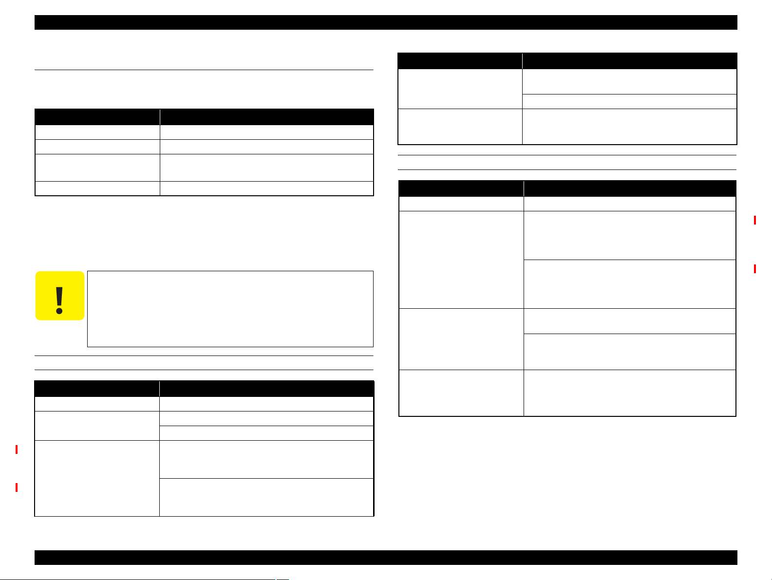
Epson Stylus Pro 7700
Epson Stylus Pro 7710
Epson Stylus Pro 7900
Epson Stylus Pro 7910
Epson Stylus Pro 9700
Epson Stylus Pro 9710
Epson Stylus Pro 9900
Epson Stylus Pro 9910
Large Format Color Inkjet Printer
SERVICE MANUAL
SEIJ08005
Confidential
Page 2

PRECAUTIONS
Precautionary notations throughout the text are categorized relative to 1) Personal injury and 2) Damage to equipment.
DANGER Signals a precaution which, if ignored, could result in serious or fatal personal injury. Great caution should be exercised in performing
procedures preceded by DANGER Headings.
WARNING Signals a precaution which, if ignored, could result in damage to equipment.
The precautionary measures itemized below should always be observed when performing repair/maintenance procedures.
DANGER
1. ALWAYS DISCONNECT THE PRODUCT FROM THE POWER SOURCE AND PERIPHERAL DEVICES PERFORMING ANY MAINTENANCE OR
REPAIR PROCEDURES.
2. NO WORK SHOULD BE PERFORMED ON THE UNIT BY PERSONS UNFAMILIAR WITH BASIC SAFETY MEASURES AS DICTATED FOR ALL
ELECTRONICS TECHNICIANS IN THEIR LINE OF WORK.
3. WHEN PERFORMING TESTING AS DICTATED WITHIN THIS MANUAL, DO NOT CONNECT THE UNIT TO A POWER SOURCE UNTIL
INSTRUCTED TO DO SO. WHEN THE POWER SUPPLY CABLE MUST BE CONNECTED, USE EXTREME CAUTION IN WORKING ON POWER
SUPPLY AND OTHER ELECTRONIC COMPONENTS.
4. WHEN DISASSEMBLING OR ASSEMBLING A PRODUCT, MAKE SURE TO WEAR GLOVES TO AVOID INJURY FROM METAL PARTS WITH
SHARP EDGES.
WARNING
1. REPAIRS ON EPSON PRODUCT SHOULD BE PERFORMED ONLY BY AN EPSON CERTIFIED REPAIR TECHNICIAN.
2. MAKE CERTAIN THAT THE SOURCE VOLTAGES IS THE SAME AS THE RATED VOLTAGE, LISTED ON THE SERIAL NUMBER/RATING
PLATE. IF THE EPSON PRODUCT HAS A PRIMARY AC RATING DIFFERENT FROM AVAILABLE POWER SOURCE, DO NOT CONNECT IT TO
THE POWER SOURCE.
3. ALWAYS VERIFY THAT THE EPSON PRODUCT HAS BEEN DISCONNECTED FROM THE POWER SOURCE BEFORE REMOVING OR
REPLACING PRINTED CIRCUIT BOARDS AND/OR INDIVIDUAL CHIPS.
4. IN ORDER TO PROTECT SENSITIVE MICROPROCESSORS AND CIRCUITRY, USE STATIC DISCHARGE EQUIPMENT, SUCH AS ANTI-STATIC
WRIST STRAPS, WHEN ACCESSING INTERNAL COMPONENTS.
5. REPLACE MALFUNCTIONING COMPONENTS ONLY WITH THOSE COMPONENTS BY THE MANUFACTURE; INTRODUCTION OF SECONDSOURCE ICs OR OTHER NON-APPROVED COMPONENTS MAY DAMAGE THE PRODUCT AND VOID ANY APPLICABLE EPSON WARRANTY.
6. WHEN AIR DUSTER IS USED ON THE REPAIR AND THE MAINTENANCE WORK, THE USE OF THE AIR DUSTER PRODUCTS CONTAINING
THE INFLAMMABLE GAS IS PROHIBITED.
Confidential
Page 3

About This Manual
This manual describes basic functions, theory of electrical and mechanical operations, maintenance and repair procedures of the printer. The instructions and procedures included
herein are intended for the experienced repair technicians, and attention should be given to the precautions on the preceding page.
Manual Configuration
This manual consists of six chapters and Appendix.
CHAPTER 1.PRODUCT DESCRIPTIONS
Provides a general overview and specifications of the product.
CHAPTER 2.OPERATING PRINCIPLES
Describes the theory of electrical and mechanical operations of the
product.
CHAPTER 3.TROUBLESHOOTING
Describes the step-by-step procedures for the troubleshooting.
CHAPTER 4.DISASSEMBLY / ASSEMBLY
Describes the step-by-step procedures for disassembling and assembling
the product.
CHAPTER 5.ADJUSTMENT
Provides Epson-approved methods for adjustment.
CHAPTER 6.MAINTENANCE
Provides preventive maintenance procedures and the lists of Epsonapproved lubricants and adhesives required for servicing the product.
CHAPTER 7.APPENDIX
Provides the following additional information for reference:
• Connectors
• Panel Menu Maps
• ASP List
• Exploded Diagrams
Symbols Used in this Manual
Various symbols are used throughout this manual either to provide additional
information on a specific topic or to warn of possible danger present during a
procedure or an action. Be aware of all symbols when they are used, and always read
NOTE, CAUTION, or WARNING messages.
Indicates an operating or maintenance procedure, practice or condition
that is necessary to keep the product’s quality.
Indicates an operating or maintenance procedure, practice, or condition
that, if not strictly observed, could result in damage to, or destruction of,
equipment.
May indicate an operating or maintenance procedure, practice or
condition that is necessary to accomplish a task efficiently. It may also
provide additional information that is related to a specific subject, or
comment on the results achieved through a previous action.
Indicates an operating or maintenance procedure, practice or condition
that, if not strictly observed, could result in injury or loss of life.
Indicates that a particular task must be carried out according to a certain
standard after disassembly and before re-assembly, otherwise the quality
of the components in question may be adversely affected.
Confidential
Page 4

Revision Status
Revision Date of Issue Description
A October 20, 2008 First release
B November 25, 2008 Full-fledged revision
C March 27, 2009 Full-fledged revision
D September 18, 2009
• Full-fledged revision
• Added Epson Stylus Pro 7700/Epson Stylus Pro 7710/Epson Stylus Pro 9700/Epson Stylus Pro 9710.
Confidential
Page 5

Epson Stylus Pro 7700/7710/7900/7910/9700/9710/9900/9910 Revision D
Contents
Chapter 1 PRODUCT DESCRIPTION
1.1 Product Description ............................................................................................ 10
1.2 Basic Specifications ............................................................................................ 13
1.2.1 Basic Specifications ................................................................................... 13
1.2.2 Electric Specifications ............................................................................... 13
1.2.3 Ink Specifications ...................................................................................... 14
1.2.4 General Specifications ............................................................................... 14
1.2.5 Reliability/Durability ................................................................................. 15
1.2.6 Auto Take-up Reel Unit ............................................................................. 16
1.3 Printing Specifications ........................................................................................ 17
1.3.1 Paper Feed Specifications .......................................................................... 17
1.3.2 Paper Specification .................................................................................... 17
1.3.3 Printable Area ............................................................................................ 28
1.3.4 Borderless Printing Specification .............................................................. 29
1.3.5 Cutting of Roll Paper ................................................................................. 30
1.4 Hardware Specifications ..................................................................................... 31
1.4.1 Dimensions and Weight ............................................................................. 31
1.4.2 Part Names ................................................................................................. 32
1.4.3 Option Correspondence Table ................................................................... 33
1.5 Control Panel ...................................................................................................... 34
1.5.1 Menu Mode Settings .................................................................................. 41
1.5.2 Maintenance Mode .................................................................................... 51
1.5.3 Serviceman Mode ...................................................................................... 52
Chapter 2 OPERATING PRINCIPLES
2.1 Main Body .......................................................................................................... 68
2.1.1 Housing ...................................................................................................... 68
2.1.2 Electric Circuit Components ..................................................................... 69
2.1.3 Carriage Mechanism .................................................................................. 70
2.1.4 APG Mechanism ........................................................................................ 71
2.1.5 Paper Feed Mechanism .............................................................................. 72
2.1.6 Ink System ................................................................................................. 73
2.2 Options ............................................................................................................... 76
2.2.1 Auto Take-up Reel ..................................................................................... 76
2.2.2 SpectroProofer ........................................................................................... 77
Chapter 3 TROUBLE SHOOTING
3.1 Overview ............................................................................................................ 79
3.1.1 Preliminary Check ..................................................................................... 79
3.1.2 Troubleshooting Procedure ........................................................................ 79
3.2 List of Error Messages ....................................................................................... 80
3.3 Remedies for Error Messages ............................................................................. 84
3.4 Remedies for Error Messages related to SpectroProofer/Auto Take-up Reel .... 92
3.5 Remedies for Maintenance Requests ................................................................. 97
3.6 Remedies for Service Call Error ........................................................................ 99
3.7 Remedies for Print Quality Troubles ................................................................ 114
6
Confidential
Page 6

Epson Stylus Pro 7700/7710/7900/7910/9700/9710/9900/9910 Revision D
Chapter 4 DISASSEMBLY & ASSEMBLY
4.1 Overview .......................................................................................................... 117
4.1.1 Precautions ............................................................................................... 117
4.1.2 Orientation Definition .............................................................................. 119
4.1.3 Recommended Tools ............................................................................... 120
4.1.4 Cautions when replacing the Main Board Assy/Power Supply Board Assy ..
121
4.1.5 Differences of the parts/components between models ............................ 122
4.2 Parts Diagram ................................................................................................... 127
4.3 Disassembly Flowchart .................................................................................... 134
4.4 Disassembly and Assembly Procedure ............................................................. 140
4.4.1 Special operation for servicing ................................................................ 140
4.4.2 Housing .................................................................................................... 142
4.4.3 Electric Circuit Components .................................................................... 167
4.4.4 Carriage Mechanism ................................................................................ 175
4.4.5 Paper Feed Mechanism ............................................................................ 189
4.4.6 Ink System Mechanism ............................................................................ 205
4.4.7 Auto Take-up Reel ................................................................................... 245
4.4.8 SpectroProofer ......................................................................................... 257
Chapter 5 ADJUSTMENT
5.1 Overview .......................................................................................................... 284
5.1.1 Precautions ............................................................................................... 284
5.1.2 Adjustment Items and the Order by Repaired Part .................................. 285
5.1.3 Description of Adjustments ..................................................................... 287
5.1.4 Tools for Adjustments ............................................................................. 289
5.1.5 Service Program Basic Operations .......................................................... 290
5.2 NV-RAM BACKUP UTILITY ........................................................................ 295
5.3 CR Related Adjustment .................................................................................... 296
5.3.1 CR Timing Belt Tension Adjustment ...................................................... 296
5.3.2 CR Encoder Sensor Adjustment .............................................................. 300
5.3.3 Head PG Adjustment ............................................................................... 301
5.3.4 Cleaning PG Adjustment ......................................................................... 303
5.4 Head Related Adjustments ............................................................................... 305
5.4.1 Head Rank ID .......................................................................................... 305
5.4.2 Head Cleaning ......................................................................................... 307
5.4.3 Nozzle Check ........................................................................................... 308
5.4.4 Printhead Slant Adjustment (CR) ............................................................ 309
5.4.5 Printhead Slant Adjustment (PF) ............................................................. 312
5.4.6 Auto Uni-D Adjustment .......................................................................... 314
5.4.7 Auto Bi-D Adjustment ............................................................................. 315
5.4.8 Colorimetric Calibration (Color ID)
with SpectroProofer ................................................................................ 316
5.4.9 Absorber Position Check ......................................................................... 332
5.4.10 Ink Mark Sensor Height Adjustment ..................................................... 333
5.4.11 Ink Mark Sensor Adjustment ................................................................. 334
5.4.12 Air Leak Check for Ink Supply System ................................................. 335
5.4.13 Initial Ink Charge Flag ON/OFF ........................................................... 337
5.4.14 Initial Ink Charge ................................................................................... 337
5.5 PF Related Adjustment ..................................................................................... 338
5.5.1 PF Timing Belt Tension Adjustment ....................................................... 338
5.5.2 Skew Check ............................................................................................. 340
5.5.3 Band Feed ................................................................................................ 341
5.5.4 T&B&S Adjustment ................................................................................ 342
5.5.5 Paper Thickness Sensor Position Adjustment ......................................... 344
5.5.6 PF Encoder Sensor Adjustment ............................................................... 347
5.5.7 Rear Sensor AD Adjustment ................................................................... 348
5.6 AID Related Adjustment .................................................................................. 349
5.6.1 AID Function check ................................................................................. 349
5.7 Other Adjustment ............................................................................................. 351
5.7.1 Setting Destination .................................................................................. 351
5.7.2 Input CR/PF Motor Current ..................................................................... 352
5.7.3 RTC and USB ID ..................................................................................... 353
5.7.4 Installing Firmware .................................................................................. 354
5.7.5 Input Serial Number ................................................................................ 356
5.7.6 Input MAC Address ................................................................................. 357
5.7.7 Cut Position Adjustment .......................................................................... 358
5.7.8 Ink Holder Adjustment ............................................................................ 359
5.8 Clear Counters .................................................................................................. 360
5.9 Tests .................................................................................................................. 361
5.9.1 Network Communication Check ............................................................. 361
5.9.2 Suction Fan Operation Check .................................................................. 361
5.9.3 Color LCD Display Check ...................................................................... 362
5.9.4 Button Operation Check .......................................................................... 362
5.9.5 Inspection of the SpectroProofer ............................................................. 363
5.10 Check Adjustments Results ............................................................................ 376
7
Confidential
Page 7

Epson Stylus Pro 7700/7710/7900/7910/9700/9710/9900/9910 Revision D
Chapter 6 MAINTENANCE
6.1 Overview .......................................................................................................... 378
6.2 Setting Up/Storing the Printer .......................................................................... 380
6.2.1 Setting Up ................................................................................................ 380
6.2.2 Storing the Printer and Cleaning the Ink Path ......................................... 380
6.3 Transportation ................................................................................................... 382
6.4 Cleaning ............................................................................................................ 383
6.5 Lubrication ....................................................................................................... 385
Chapter 7 APPENDIX
7.1 Block Wiring Diagram ..................................................................................... 393
7.1.1 Main Body ............................................................................................... 393
7.1.2 Auto Take-up Reel ................................................................................... 394
7.1.3 SpectroProofer ......................................................................................... 394
7.2 Panel Menu Map ............................................................................................... 395
7.2.1 Epson Stylus Pro 7900/7910/9900/9910 ................................................. 395
7.2.2 Epson Stylus Pro 7700/7710/9700/9710 ................................................. 398
7.3 Part names used in this manual ........................................................................ 401
7.4 Parts List ........................................................................................................... 403
7.5 Exploded Diagram ............................................................................................ 412
8
Confidential
Page 8

PRODUCT DESCRIPTION
CHAPTER
1
Confidential
Page 9
Epson Stylus Pro 7700/7710/7900/7910/9700/9710/9900/9910 Revision D
1.1 Product Description
Epson Stylus Pro 7700/7710/7900/7910/9700/9710/9900/9910 is a wide-format color
inkjet printer that supports up to 44 inch-wide (Super B0)/24 inch-wide (Super A1)
paper. The main features are;
Supports very large-sized paper
Maximum available paper width:
Epson Stylus Pro 9700/9710/9900/9910: 1,118 mm (44 inch)
Epson Stylus Pro 7700/7710/7900/7910: 610 mm (24 inch)
Ink configuration
Epson Stylus Pro 7900/7910/9900/9910
Installs the following 11 ink cartridges including newly developed
colors; orange and green. The ink selector function is equipped, and
black ink can be switched between Photo Black and Matte Black
depending on media type.
Table 1-1. Ink Colors (Epson Stylus Pro 7900/7910/9900/9910)
Color Abbreviation
Photo Black PK
Matte Black MK
Cyan C
Vivid Magenta VM
Yellow Y
Light Cyan Lc
Orange O
Green G
Light Cyan LC
Vivid Light Magenta VLM
Light Black LK
Light Light Black LLK
Epson Stylus Pro 7700/7710/7900/7910
Consists of the following 5 colors. Switching between photo Black and
Matte Black by the ink selector is not necessary, because ink is
assigned in colors by nozzles.
Table 1-2. Ink Colors (Epson Stylus Pro 7700/7710/9700/9710)
Color Abbreviation
Photo Black PK
Matte Black MK
Cyan C
Vivid Magenta VM
Yellow Y
Super high print quality
Achieves high quality printing with 11 colors of ink, resolution of up to 2880 x
1440 dpi, and variable dot sizes (minimal 3.5 picoliter)
For Epson Stylus Pro 7700/7710/9700/9710, the ink consists of 5 colors.
Lower running cost
Employs super high-capacity independent ink cartridges
Equips the on-demand cleaning function without excessive suction of ink
using the independent ink suction system for every two rows and the AID
function
Media handling
Supports a variety of media
Spindle-less makes roll paper handling easier
Paper basket comes as standard
Stores roll paper usage history and updates it automatically by reading a
barcode. This enables automatic detection of remaining amount of the paper.
Equips high speed auto cutter for roll paper
Borderless print is supported
The latest-type RIP
Supports software RIP made by other companies
PRODUCT DESCRIPTION Product Description 10
Confidential
Page 10

Epson Stylus Pro 7700/7710/7900/7910/9700/9710/9900/9910 Revision D
Options
The following options are available.
Auto Take-up Reel (Epson Stylus Pro 9700/9710/9900/9910 only)
Winds the roll paper automatically
SpectroProofer
Enables color measurement after printing
PRODUCT DESCRIPTION Product Description 11
Confidential
Page 11

Epson Stylus Pro 7700/7710/7900/7910/9700/9710/9900/9910 Revision D
SpectroProofer (Option)
Mounting the SpectroProofer equipped with the drying function makes
automatic color measurement after printing available.
Full-fledged spectrophotometer realizes high precision color measurement.
Selectable from specifications with/without the UV filter, which enables the
users to configure colorimetric system adjusted with their workflow
Cooling fans for drying ink stabilizes color in less than 2 minutes.
Paper pressing function prevents degrading precision of colorimetry caused
by floating of paper.
Selectable from the white backing or the black backing
Figure 1-1. External View (Main body)
Figure 1-2. External View (SpectroProofer)
PRODUCT DESCRIPTION Product Description 12
Confidential
Page 12
Epson Stylus Pro 7700/7710/7900/7910/9700/9710/9900/9910 Revision D
1.2 Basic Specifications
1.2.1 Basic Specifications
Specification
Item
Print method On-demand inkjet
Nozzle configuration
Printing direction
Maximum resolution 2,880dpi x 1,440dpi
Control code ESC/P2, ESC/P3 (commands are nondisclosure)
Paper feed method Friction
RAM 256 MB for Main, 64 MB for Network
Interface
Epson Stylus Pro 7900/7910/
9900/9910
Black system:
360 nozzles x three colors
(Photo black/Matte black, Light
black, Light light black)
Color system:
360 nozzles x seven colors
(Cyan, Light Cyan, Vivid
magenta, Vivid light magenta,
Yellow, Orange, Green)
Bi-directional shortest-direction printing
(high-speed return, high-speed skip)
USB 2.0 High Speed
Ethernet 10/100
Epson Stylus Pro 7700/7710/
9700/9710
Black system:
360 nozzles x two rows x two
colors (Photo black, Matte black)
Color system:
360 nozzles x two rows x three
colors (Cyan, Vivid magenta,
Yellow)
1.2.2 Electric Specifications
Specification
Item
Rated voltage 100 to 240 VAC
Input voltage range 90 to 264 VAC
Rated frequency 50 to 60 Hz
Input frequency range 49.5 to 60.5 Hz
Rated current 1.0 A to 0.5 A
Power
consumption
Insulation resistance 10MΩ or more (between AC line and chassis at 500 VDC)
Dielectric strength
Leek current 0.25 mA or less
Compliance with regulations
Operating Approx. 80 W Approx. 70 W
Sleep mode Approx. 16 W
Standby Less than 1W
Epson Stylus Pro 9700/9710/
9900/9910
1.0 kVrms AC for 1 min. or 1.2 kVrms AC for 1 sec.
(between AC line and chassis)
Conforms to International Energy Star Program
(Category: the harmonic restraint measure guideline)
Conforms to VCCI Class B (with full options installed)
Epson Stylus Pro 7700/7710/
7900/7910
PRODUCT DESCRIPTION Basic Specifications 13
Confidential
Page 13

Epson Stylus Pro 7700/7710/7900/7910/9700/9710/9900/9910 Revision D
1.2.3 Ink Specifications 1.2.4 General Specifications
Specification
Item
Form Exclusive ink cartridge
Pigment Ink colors
Cartridge life
Guaranteed life after installation Within 6 months after mounted in the printer
Uninstalled
(packed)
Storage
Capacity 350 ml/700 ml 150 ml/350 ml/700 ml
Dimensions
Maintenance Tank C12C890191 / C12C890193 C12C890501 / C12C890502
Installed
Transporting
(packed)
150 ml N/A 40 (W) x 240 (L) x 107 (H)
350 ml 40 (W) x 240 (L) x 107 (H)
700ml 40 (W) x 320 (L) x 107 (H)
Epson Stylus Pro 7900/7910/
9900/9910
Black system: Photo black,
Matte black, Light black,
Light light black
Color system: Cyan, Light
Cyan, Vivid magenta, Vivid
light magenta, Yellow,
Orange, Green
By the date written on the package or the cartridge (at normal
(within 1 month under 40 °C)
(within 1 month under 40 °C)
(within 72 hours under 60 °C, and within 1 month under 40
Epson Stylus Pro 7700/7710/
9700/9710
Black system: Photo black,
Matte black
Color system: Cyan, Vivid
magenta, Yellow
temperature)
-20 to 40 °C
-20 to 40°C
-20 to 60 °C
°C)
Temperature
Humidity
Item Specification
Operating: 10 to 35 °C
Storage (before unpacked): -20 to 60 °C
(within 120 hours under 60 °C, and within 1 month under 40 °C)
Storage (after unpacked): -20 to 40 °C
(within 1 month under 40°C)
Operating: 20 to 80% (no condensation)
Storage (before unpacked):
-20 to 85% (no condensation)
Storage (after unpacked):
5 to 85% (no condensation)
Humidity (%)
Temperature (°C)
C A U T I O N
Ink will be frozen if left under below -15°C circumstances for a
long time. In such a case, leave it in the room temperature more
than 4 hours to melt the frozen ink before using it. (no
condensation)
Never disassemble ink cartridges or refill ink in them.
PRODUCT DESCRIPTION Basic Specifications 14
Confidential
Page 14
Epson Stylus Pro 7700/7710/7900/7910/9700/9710/9900/9910 Revision D
1.2.5 Reliability/Durability
Main Body
Specification
Item
Operating life of the printer
Cutter life (reference)
RTC backup battery* 5 years or longer
Pump Cap motor
Parts life
CR motor*, Drive pulley*, Carriage unit*,
FFC*
Ink tube 10,000,000 paths 5,800,000 paths
Epson Stylus Pro 9900/
Epson Stylus Pro 9910
Until any one of the following
conditions is met.
5 years
Carriage life: 5,000,000 paths
Approx. 20,000 pages
(Super B0 size/Plain paper,
Quality mode/720x360 dpi)
Auto cutter: Total 100,000 cuts or more (Only genuine media are guaranteed.)
Epson Stylus Pro 7900/
Epson Stylus Pro 7910
Until any one of the following
conditions is met.
5 years
Carriage life: 5,000,000 paths
Approx. 20,000 pages
(Super B0 size/Plain paper,
Quality mode/720x720 dpi)
Standard paper: approx. 20,000 cuts or more
Hard cut paper: approx. 5,000 cuts or more
Approx. 20,000 pages (reference value)
(Super B0 size /EPSON paper/Quality mode/Continuous printing/
720x720 dpi)
Approx. 5,000,000 paths Approx. 2,900,000 paths
Epson Stylus Pro 9700/
Epson Stylus Pro 9710
Until any one of the following
conditions is met.
5 years
Carriage life: 2,900,000 paths
Approx. 20,000 pages
(Super A1 size/Plain paper/
Quality mode/720x360 dpi)
Epson Stylus Pro 7700/
Epson Stylus Pro 7710
Until any one of the following
conditions is met.
5 years
Carriage life: 2,900,000 paths
Approx. 20,000 pages
(Super A1 size/Plain paper/
Quality mode/720x720 dpi)
Approx. 20,000 pages (reference value)
(Super A1 size /EPSON paper/Quality mode/Continuous printing/
720x720 dpi)
Note *: These values are provided only as a guide. Service call is not indicated for these parts.
SpectroProofer
Item Specifiied values
Until any one of the following conditions is met.
Mounter
5 years
200,000 paths for color measurement
PRODUCT DESCRIPTION Basic Specifications 15
Confidential
Page 15

Epson Stylus Pro 7700/7710/7900/7910/9700/9710/9900/9910 Revision D
1.2.6 Auto Take-up Reel Unit
Item Specifiied values
Paper Width 406 to 1,118 mm
Paper length
Rotation speed Max. 40 rpm
Weight 6.9 kg
Environment
Rated voltage AC 100 to 240 V
Input voltage range AV 90 to 264 V
Rated frequency range 50 to 60 Hz
Input frequency range 49.5 to 60.5 Hz
Rated current 0.2 A
Power consumption
2-inch core: 1.3 to 40 m
3-inch core: 1.6 to 30.5 m
Temperature: 10 to 35 °C
Humidity: 20 to 80 %
Approx. 9 W
Approx. 3 W in Ready Mode
PRODUCT DESCRIPTION Basic Specifications 16
Confidential
Page 16
Epson Stylus Pro 7700/7710/7900/7910/9700/9710/9900/9910 Revision D
1.3 Printing Specifications
1.3.1 Paper Feed Specifications
Item Specification
Paper feed method Friction feed
Return pitch 2.2049
Paper feeder
Feed speed 300 ms/ (1/6 inch)
1.3.2 Paper Specification
1.3.2.1 Supported Paper
The following explains the supported paper sizes and thickness.
C A U T I O N
ROLL PAPER
Paper type Plain paper, recycled paper, others
Roll paper size
Paper size W x L (within roll
paper size)
Do not use wrinkled, scuffed, torn, or soiled paper.
Load paper just before printing. Do not leave paper loaded on
the printer when not printing. Store paper properly following
the instruction that comes with the paper.
When large quantities of paper need to be prepared in advance,
make a test print using the paper before purchase.
Item Specification
μm (1/11,520 inch)
Roll paper manual feed
Cut sheet manual feed
2-inch core: Outer diameter 103 mm or less x 1 roll
3-inch core: Outer diameter 150 mm or less x 1 roll
Epson Stylus Pro 9700/9710/9900/9910:
2-inch core: 254 to 1118 mm x 45 m
3-inch core: 254 to 1118 mm x 202 m
Epson Stylus Pro 7700/7710/7900/7910:
2-inch core: 254 to 610 mm x 45 m
3-inch core: 254 to 610 mm x 202 m
Item Specification
Plain paper, recycled paper:
Paper thickness
Available width for borderless
printing
0.08 to 0.11 mm (Weight: 64 to 90 g/m2)
Others: 0.08 to 0.50 mm
10 inches, 300 mm, 13 inches (Super A3), 16 inches, 17
inches, 515 mm (B2), 594 mm (A1), 24 inches (Super A1),
728 mm (B1), 36 inches (Super A0), 44 inches (Super B0)
CUT SHEET
Item Specification
Paper type Plain paper, recycled paper, others
Epson Stylus Pro 9700/9710/9900/9910:
Width: 210 to 1118 mm
Length: 279.4 to 1580 mm
Paper type
Paper thickness
Available width for borderless
printing
(A4 to Super B0)
Epson Stylus Pro 7700/7710/7900/7910:
Width: 210 to 610 mm
Length: 279.4 to 914 mm
(A4 to Super A1)
Plain paper, recycled paper: 0.08 to 0.11 mm
(Weight: 64 to 90 g/m2)
Others:
Length 279 to 728 mm: 0.08 to 1.50 mm
Length over 728 to 2032 mm: 0.08 to 0.50 mm
10 inches, 300 mm, 13 inches (Super A3),
16 inches, 17 inches, 515 mm (B2), 594 mm (A1),
24 inches (Super A1), 728 mm (B1),
36 inches (Super A0), 44 inches (Super B0)
PRODUCT DESCRIPTION Printing Specifications 17
Confidential
Page 17

Epson Stylus Pro 7700/7710/7900/7910/9700/9710/9900/9910 Revision D
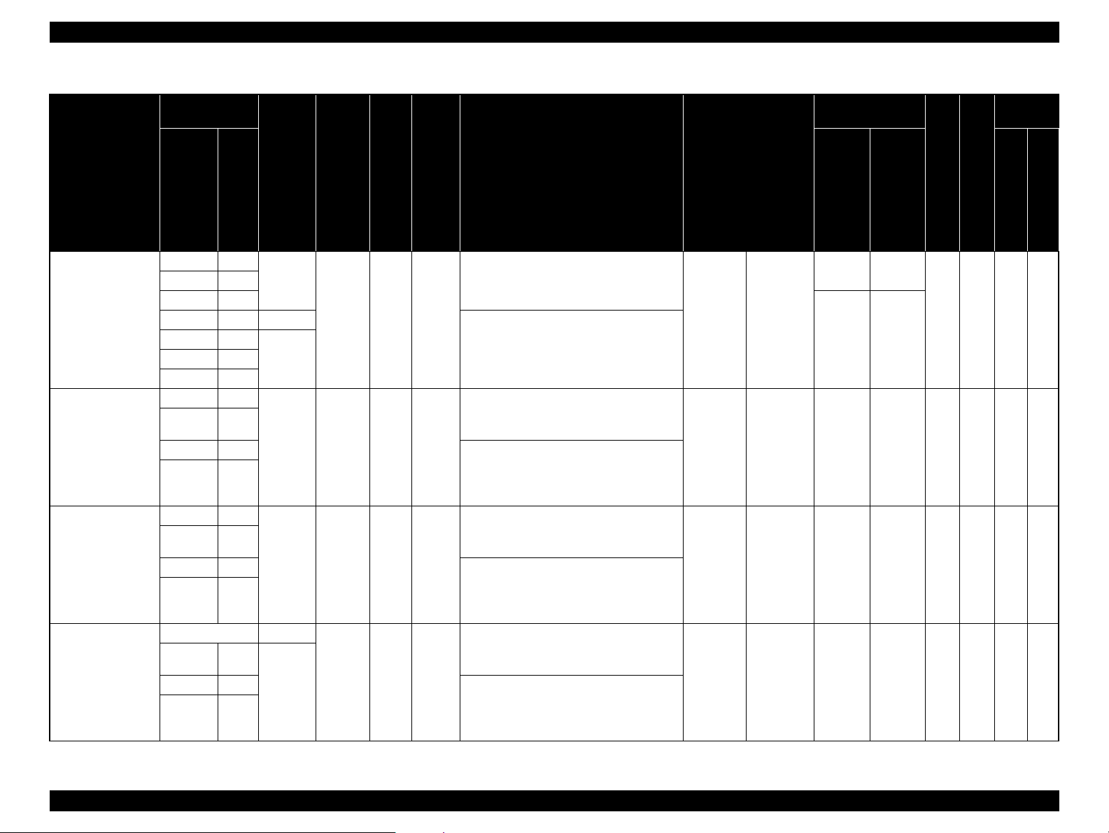
1.3.2.2 Designated Paper
ROLL PAPER
Note *1 : OK!: Recommended for borderless printing
OK: Borderless printing is available
NA: Borderless printing is NOT available
Borderless printing on the borderless printing available paper (OK) may result in drop in print quality or fail to produce complete borderless (white margins may appear) due to expanding of
the paper. Borderless printing can be made on commercially available paper, however, note that the availability is restricted by the paper size.
*2: Not supported for Epson Stylus Pro 7700/7710/7900/7910.
*3: Auto Take-up Reel Unit is used. (only Pro 9700/9710/9900/9910)
*4: When using the tensioner included in the Auto Take-up Reel Unit of Pro 9700/9710/9900/9910.
Table 1-3. Designated Roll Paper List
Size
Take-up*
3
Applied
model
Name
Premium Glossy
Photo Paper (250)
Premium Semigloss
Photo Paper (250)
mm
406mm 16"
610mm 24"
914mm*
1118mm*344"*
406mm 16"
610mm 24"
914mm*
1118mm*244"*
inch
2
36"*
2
36"*
Borderless
Print
2
2
2
2
Thickness
*1
OK! 0.27mm 3" Standard
OK! 0.27mm 3" Standard
Core
Diameter
Roll
Paper
Tension
Upper: Pro7900/7910/9900/9910
ICC Profile
Lower:Pro7700/7710/9700/9710
• Photo Black: Pro9900_7900
PremiumGlossyPhotoPaper250.icc
• Matte Black: ---
• Photo Black: Epson Stylus Pro
7700_7710_9700_9710
PremiumGlossyPhotoPaper250.icc
• Matte Black: ---
• Photo Black: Pro9900_7900
PremiumGlossyPhotoPaper250.icc
• Matte Black: ---
• Photo Black: Epson Stylus Pro
7700_7710_9700_9710
PremiumGlossyPhotoPaper250.icc
• Matte Black: ---
Driver Setting
Photo Paper
Photo Paper
Premium
Glossy
Photo Paper
(250)
Premium
Semigloss
Photo Paper
(250)
Auto
Black
Cut
Forward Backward
Ink
Pro7900/7910/9900/9910
33OK PK 33
33OK PK 33
Pro7700/7710/9700/9710
PRODUCT DESCRIPTION Printing Specifications 18
Confidential
Page 18
Epson Stylus Pro 7700/7710/7900/7910/9700/9710/9900/9910 Revision D
Table 1-3. Designated Roll Paper List
Size
Take-up*
3
Applied
model
Name
Premium Luster Photo
Paper (260)
Premium Semimatte
Photo Paper (260)
Photo Paper Gloss 250
Premium Glossy
Photo Paper (170)
Borderless
mm
inch
254mm 10"
300mm 12"
406mm 16"
508mm 20" NA
610mm 24"
2
2
36"*
1118mm*244"*
2
406mm 16"
610mm 24"
2
2
914mm*
1118mm*244"*
36"*
2
432mm 17"
610mm 24"
2
2
914mm*
1118mm*244"*
36"*
2
420mm (A2) NA
610mm 24"
2
2
914mm*
1118mm*244"*
36"*
2
Roll
Paper
Tension
Print
*1
Thickness
Core
Diameter
OK!
0.27mm 3" Standard
OK!914mm*
OK! 0.27mm 3" Standard
OK! 0.25mm 3" Normal
OK!
0.18mm 2" Standard
Upper: Pro7900/7910/9900/9910
ICC Profile
Lower:Pro7700/7710/9700/9710
• Photo Black: Pro9900_7900
PremiumLusterPhotoPaper260.icc
• Matte Black: ---
• Photo Black: Epson Stylus Pro
7700_7710_9700_9710
PremiumLusterPhotoPaper260.icc
• Matte Black: ---
• Photo Black: Pro9900_7900
PremiumSemimattePhotoPaper260.icc
• Matte Black: ---
• Photo Black: Epson Stylus Pro
7700_7710_9700_9710
PremiumSemimattePhotoPaper260.icc
• Matte Black: ---
• Photo Black: Pro9900_7900
PhotoPaperGloss250.icc
• Matte Black: ---
• Photo Black:Epson Stylus Pro
7700_7710_9700_9710PhotoPaperGloss
250.icc
• Matte Black: ---
• Photo Black: Pro9900_7900
PremiumGlossyPhotoPaper170.icc
• Matte Black: ---
• Photo Black:Epson Stylus
Pro7700_7710_9700_9710
PremiumGlossyPhotoPaper170.icc
• Matte Black: ---
Driver Setting
Photo Paper
Photo Paper
Photo Paper
Photo Paper
Premium
Luster Photo
Paper (260)
Premium
Semimatte
Photo Paper
(260)
Photo Paper
Gloss 250
Premium
Glossy
Photo Paper
(170)
Auto
Black
Cut
Forward Backward
Ink
Pro7900/7910/9900/9910
NA NA
OK PK 33
33
33OK PK 33
33OK PK 33
33OK PK 33
Pro7700/7710/9700/9710
PRODUCT DESCRIPTION Printing Specifications 19
Confidential
Page 19

Epson Stylus Pro 7700/7710/7900/7910/9700/9710/9900/9910 Revision D
Table 1-3. Designated Roll Paper List
Size
Take-up*
3
Applied
model
Name
Premium Semigloss
Photo Paper (170)
Epson Proofing Paper
White Semimatte
Epson Proofing Paper
Publication
Epson Proofing Paper
Commercial
mm
420mm (A2) NA
610mm 24"
914mm*
1118mm*244"*
330mm 13"
432mm 17"
610mm 24"
914mm*236"*
1118mm*244"*
330mm 13"
432mm 17"
610mm 24"
914mm*236"*
1118mm*244"*
330mm 13"
432mm 17"
610mm 24"
914mm*236"*
1118mm*244"*
inch
2
2
36"*
2
2
2
2
2
2
2
Borderless
Print
Thickness
*1
OK!
OK 0.25mm 3" Standard
OK 0.20mm 3" Standard
OK 0.20mm 3" Standard
0.18mm 2" Standard
Core
Diameter
Roll
Paper
Tension
Upper: Pro7900/7910/9900/9910
ICC Profile
Lower:Pro7700/7710/9700/9710
• Photo Black: Pro9900_7900
PremiumSemiglossPhotoPaper170.icc
• Matte Black: ---
• Photo Black: Epson Stylus
Pro7700_7710_9700_9710
PremiumSemiglossPhotoPaper170.icc
• Matte Black: ---
• Photo Black: Pro9900_7900
EpsonProofingPaperWhiteSemimatte.icc
• Matte Black: ---
---
• Photo Black: Pro9900_7900
EpsonProofingPaperPublication.icc
• Matte Black: ---
---
• Photo Black: Pro9900_7900
EpsonProofingPaperCommercial.icc
• Matte Black: ---
---
Driver Setting
Photo Paper
Proofing
Paper
Proofing
Paper
Proofing
Paper
Premium
Semigloss
Photo Paper
(170)
Epson
Proofing
Paper White
Semimatte
Epson
Proofing
Paper
Publication
Epson
Proofing
Paper
Commercial
Auto
Black
Cut
Forward Backward
Ink
Pro7900/7910/9900/9910
33OK PK 33
--- ---
33
--- ---
33
--- ---
33
OK PK
OK PK
OK PK
3
3
3
Pro7700/7710/9700/9710
PRODUCT DESCRIPTION Printing Specifications 20
Confidential
Page 20

Epson Stylus Pro 7700/7710/7900/7910/9700/9710/9900/9910 Revision D
Table 1-3. Designated Roll Paper List
Size
Take-up*
3
Applied
model
Name
Enhanced Synthetic
Paper
Enhanced Adhesive
Synthetic Paper
Doubleweight Matte
Paper
mm
inch
610mm 24"
1118mm*244"*
610mm 24"
1118mm*244"*
610mm 24"
914mm*236"*
2
1118mm*
44"*
Borderless
*1
Print
Thickness
Core
Diameter
OK 0.12mm 2" Higher
2
OK 0.17mm 2" High
2
2
OK! 0.21mm 2" Standard
2
Roll
Paper
Tension
Upper: Pro7900/7910/9900/9910
ICC Profile
Lower:Pro7700/7710/9700/9710
• Photo Black: ---
• Matte Black: Pro9900_7900
EnhancedSyntheticPaper.icc
• Photo Black: ---
• Matte lack: Epson Stylus
Pro7700_7710_9700_9710
EbhancedSynthetic Paper.icc
• Photo Black: ---
• Matte Black: Pro9900_7900
EnhancedAdhesiveSyntheticPaper.icc
• Photo Black: ---
• Matte Black: Epson Stylus
Pro7700_7710_9700_9710
EnhancedAdhesiveSyntheticPaper.icc
• Photo Black: ---
• Matte Black: Pro9900_7900
DoubleweightMattePaper.icc
• Photo Black: ---
• Matte Black: Epson Stylus
Pro7700_7710_9700_9710
DoubleweightMattePaper.icc
Driver Setting
Others
Others
Matte Paper
Enhanced
Synthetic
Paper
Enhanced
Adhesive
Synthetic
Paper
Doubleweig
ht Matte
Paper
Auto
Black
Cut
Forward Backward
Ink
Pro7900/7910/9900/9910
33OK MK 33
33OK MK 33
4
3*
NA OK MK 33
Pro7700/7710/9700/9710
PRODUCT DESCRIPTION Printing Specifications 21
Confidential
Page 21
Epson Stylus Pro 7700/7710/7900/7910/9700/9710/9900/9910 Revision D
Table 1-3. Designated Roll Paper List
Size
Take-up*
3
Applied
model
Name
Enhanced Matte Paper
Singleweight Matte
Paper
Singleweight Matte
Paper (Line Drawing)
Watercolor Paper Radiant White
mm
inch
432mm 17"
610mm 24"
2
914mm*
1118mm*
36"*
2
44"*
432mm 17"
610mm 24"
2
914mm*
1118mm*
36"*
2
44"*
432mm 17"
610mm 24"
2
914mm*
1118mm*
36"*
2
44"*
610mm 24"
2
36"*
1118mm*244"*
Borderless
Print
2
2
2
2
2
2
2
2
Thickness
*1
OK 0.25mm 3" Standard
OK! 0.14mm 2" Standard
OK! 0.14mm 2" Standard
OK 0.29mm 3" High
Core
Diameter
Roll
Paper
Tension
Upper: Pro7900/7910/9900/9910
ICC Profile
Lower:Pro7700/7710/9700/9710
• Photo Black: Pro9900_7900
EnhancedMattePaper_PK.icc
• Matte Black: Pro9900_7900
EnhancedMattePaper_MK.icc
• Photo Black: ---
• Matte Black: Epson Stylus
Pro7700_7710_9700_9710
EnhancedMattePosterBoard.icc
• Photo Black: ---
• Matte Black:
Pro9900_7900SingleweightMattePaper.icc
• Photo Black: ---
• Matte Black: Epson Stylus
Pro7700_7710_9700_9710
SingleweightMattePaper.icc
---
• Photo Black: ---
• Matte Black: Epson Stylus
Pro7700_7710_9700_9710
SingleweightMattePaper.icc
• Photo Black: Pro9900_7900
WatercolorPaper-RadiantWhite_PK.icc
• Matte Black: Pro9900_7900
WatercolorPaper-RadiantWhite_MK.icc
---
Driver Setting
Matte Paper
Matte Paper
Matte Paper
Fine Art
Paper
Enhanced
Matte Paper
Singleweight
Matte Paper
Singleweight
Matte Paper
(Line
Drawing)
Watercolor
Paper -
Radiant
White
Auto
Black
Cut
Forward Backward
Ink
Pro7900/7910/9900/9910
3 NA OK MK 33
4
3*
3*
33OK
NA OK MK 33
4
NA OK MK 3
PK/
MK
3914mm*
Pro7700/7710/9700/9710
PRODUCT DESCRIPTION Printing Specifications 22
Confidential
Page 22

Epson Stylus Pro 7700/7710/7900/7910/9700/9710/9900/9910 Revision D
Table 1-3. Designated Roll Paper List
Size
Take-up*
3
Applied
model
Name
UltraSmooth Fine Art
Paper
Textured Fine Art
Paper
Canvas
mm
432mm 17"
610mm 24"
1118mm*
432mm 17"
610mm 24"
914mm*
1118mm*244"*
610mm 24"
1118mm*244"*
inch
2
44"*
2
36"*
2
36"*
Borderless
Print
2
2
2
2
2
Thickness
*1
OK 0.32mm 3" High
OK 0.37mm 3" High
OK 0.46mm 2" Standard
Core
Diameter
Roll
Paper
Tension
Upper: Pro7900/7910/9900/9910
ICC Profile
Lower:Pro7700/7710/9700/9710
• Photo Black: Pro9900_7900
UltraSmoothFineArtPaper_PK.icc
• Matte Black: Pro9900_7900
UltraSmoothFineArtPaper_MK.icc
---
• Photo Black: Pro9900_7900
TexturedFineArtPaper_PK.icc
• Matte Black: Pro9900_7900
TexturedFineArtPaper_MK.icc
---
• Photo Black: Pro9900_7900
Canvas_PK.icc
• Matte Black: Pro9900_7900
Canvas_MK.icc
---
Driver Setting
Fine Art
Paper
Fine Art
Paper
Fine Art
Paper
UltraSmooth
Fine Art
Paper
Textured
Fine Art
Paper
Canvas
Forward Backward
33OK
33OK
33OK
Auto
Cut
Black
Ink
PK/
MK
PK/
MK
PK/
MK
3
3
3914mm*
Pro7900/7910/9900/9910
Pro7700/7710/9700/9710
PRODUCT DESCRIPTION Printing Specifications 23
Confidential
Page 23

Epson Stylus Pro 7700/7710/7900/7910/9700/9710/9900/9910 Revision D
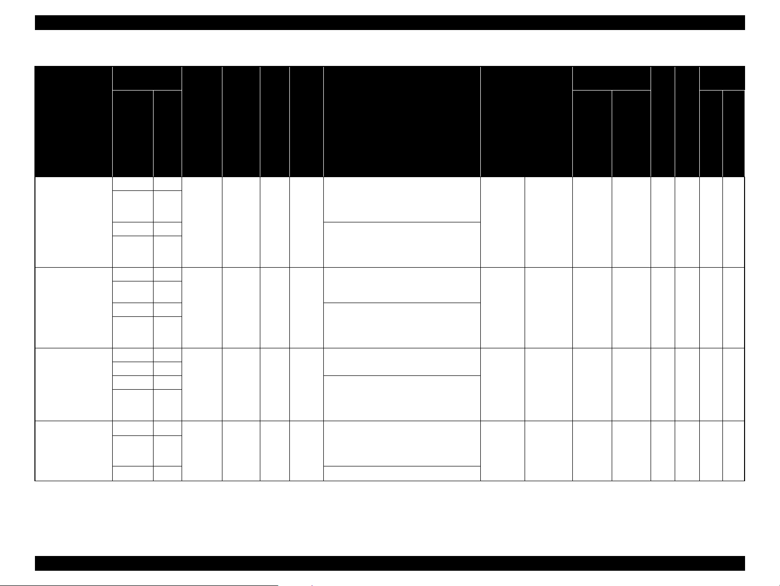
CUT SHEET
Note *1 : OK!: Recommended for borderless printing
OK: Borderless printing is available
NA: Borderless printing is NOT available
Borderless printing on the borderless printing available paper (OK) may result in drop in print quality or fail to produce complete borderless (white margins may appear) due to expanding of
the paper. Borderless printing can be made on commercially available paper, however, note that the availability is restricted by the paper size.
*2: Not supported for Epson Stylus Pro 7700/7710.
Table 1-4. Designated Cut Sheet List
Applied model
Name Size
Premium Glossy Photo Paper
Premium Semigloss Photo Paper
Borderless
Print
Super A3/B OK
A2 NA
Super A3/B OK
A2 NA
US-C OK NA
*1
Thickness
0.27mm
0.27mm
• Photo Black:
• Matte Black: ---
• Photo Black:
• Matte Black: ---
• Photo Black:
• Matte Black: ---
• Photo Black:
• Matte Black: ---
Upper: Pro7900/7910/9900/9910
Lower: Pro7700/7710/9700/9710
Pro9900_7900PremiumGlossyPhotoPaper.icc
Epson Stylus Pro
7700_7710_9700_9710PremiumGlossyPhotoPaper.icc
Pro9900_7900PremiumSemiglossPhotoPaper.icc
Epson Stylus Pro
7700_7710_9700_9710PremiumSemiglossPhotoPaper.ic
c
ICC Profile
Driver Setting Black Ink
Photo Paper
Photo Paper
Premium Glossy
Photo Paper
Premium
Semigloss
Photo Paper
PK ✔✔
PK
Pro7900/7910/9900/9910
✔
Pro7700/7710/9700/9710
✔
PRODUCT DESCRIPTION Printing Specifications 24
Confidential
Page 24

Epson Stylus Pro 7700/7710/7900/7910/9700/9710/9900/9910 Revision D
Table 1-4. Designated Cut Sheet List
Applied model
Name Size
Premium Luster Photo Paper
Archival Matte Paper/Enhanced
Matte Paper
Singleweight Matte Paper
Borderless
Print
Super A3/B OK
A2 NA
US-C OK NA
Super A3/B OK
A2 NA
US-C OK NA
Super A3/B OK
A2 NA
*1
Thickness
0.27mm
0.26mm
0.14mm
• Photo Black:
• Matte Black: ---
• Photo Black:
• Matte Black: ---
• Photo Black:
• Matte Black: ---
• Photo Black: ---
• Matte Black:
• Photo Black: ---
• Matte Black:
Upper: Pro7900/7910/9900/9910
Lower: Pro7700/7710/9700/9710
Pro9900_7900PremiumLusterPhotoPaper.icc
Epson Stylus Pro
7700_7710_9700_9710PremiumLusterPhotoPaper.icc
Pro9900_7900ArchivalMattePaper_PK.icc
Pro9900_7900ArchivalMattePaper_MK.icc
Epson Stylus Pro
7700_7710_9700_9710ArchivalMattePaper.icc
Epson Stylus Pro
7700_7710_9700_9710EnhancedMattePaper.icc
Pro9900_7900SingleweightMattePaper.icc
ICC Profile
---
Driver Setting Black Ink
Photo Paper
Matte Paper
Matte Paper
Premium Luster
Photo Paper
Archival Matte
Paper/
Enhanced Matte
Paper
Singleweight
Matte Paper
PK
PK/MK
MK ✔
Pro7900/7910/9900/9910
✔
✔
Pro7700/7710/9700/9710
✔
✔
PRODUCT DESCRIPTION Printing Specifications 25
Confidential
Page 25

Epson Stylus Pro 7700/7710/7900/7910/9700/9710/9900/9910 Revision D
Table 1-4. Designated Cut Sheet List
Applied model
Name Size
Super A3 OK
Photo Quality Inkjet Paper
Epson Proofing Paper White
Semimatte
Watercolor Paper - Radiant White Super A3/B OK 0.29mm
UltraSmooth Fine Art Paper
A2 NA
US-C OK
Super A3/B OK 0.25mm
Super A3 OK
A2 NA
Borderless
*1
Print
Thickness
0.12mm
0.46mm
Upper: Pro7900/7910/9900/9910
ICC Profile
Lower: Pro7700/7710/9700/9710
• Photo Black:
Pro9900_7900PhotoQualityInkJetPaper.icc
• Matte Black: ---
• Photo Black: ---
• Matte Black:
Epson Stylus Pro7700_7710_9700_9710PhotoQualityInk
Paper.icc
• Photo Black:
Pro9900_7900EpsonProofingPaperWhiteSemimatte.icc
• Matte Black: ---
• Photo Black:
Pro9900_7900WatercolorPaper-RadiantWhite_PK.icc
• Matte Black:
Pro9900_7900WatercolorPaper-RadiantWhite_MK.icc
• Photo Black:
Pro9900_7900UltraSmoothFineArtPaper_PK.icc
• Matte Black:
Pro9900_7900UltraSmoothFineArtPaper_MK.icc
---
Driver Setting Black Ink
Matte Paper
Proofing Paper
Fine Art Paper
Fine Art Paper
Photo Quality
Inkjet Paper
Epson Proofing
Paper
White Semimatte
Watercolor Paper
-
Radiant White
UltraSmooth
Fine
Art Paper
MK
NA
PK/MK ✔
PK/MK ✔
PK/MK ✔
Pro7900/7910/9900/9910
✔
Pro7700/7710/9700/9710
✔
• Photo Black:
Pro9900_7900VelvetFineArtPaper_PK.icc
• Matte Black:
Pro9900_7900VelvetFineArtPaper_MK.icc
---
Fine Art Paper
Velvet Fine
Art Paper
PK/MK ✔
Velvet Fine Art Paper
Super A3/B OK
0.48mm
A2 NA
PRODUCT DESCRIPTION Printing Specifications 26
Confidential
Page 26

Epson Stylus Pro 7700/7710/7900/7910/9700/9710/9900/9910 Revision D
Table 1-4. Designated Cut Sheet List
Applied model
Name Size
Textured Fine Art Paper
Enhanced Matte Posterboard
24" x 30"
36" x 44"
24" x 30"
30" x 40"*
Borderless
Print
OK 0.67mm
OK 1.30mm
2
*1
Thickness
Upper: Pro7900/7910/9900/9910
ICC Profile
Lower: Pro7700/7710/9700/9710
• Photo Black:
Pro9900_7900TexturedFineArtPaper_PK.icc
• Matte Black:
Pro9900_7900TexturedFineArtPaper_MK.icc
---
• Photo Black:
Pro9900_7900EnhancedMattePosterBoard_PK.icc
• Matte Black:
Pro9900_7900EnhancedMattePosterBoard_MK.icc
• Photo Black: ---
• Matte Black:
Epson Stylus Pro
7700_7710_9700_9710EnhancedMattePosterBoard.icc
Driver Setting Black Ink
Fine Art Paper
Others
Textured Fine
Art Paper
Enhanced Matte
Poster Board
Pro7900/7910/9900/9910
PK/MK ✔
PK/MK ✔✔
Pro7700/7710/9700/9710
PRODUCT DESCRIPTION Printing Specifications 27
Confidential
Page 27
Epson Stylus Pro 7700/7710/7900/7910/9700/9710/9900/9910 Revision D
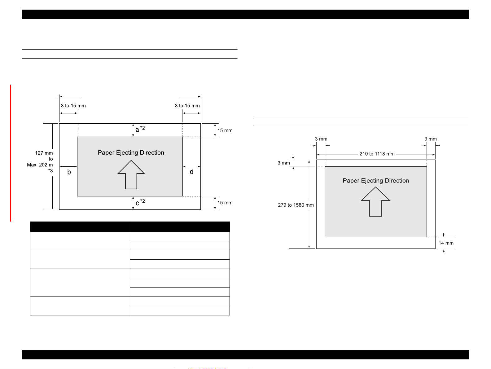
1.3.3 Printable Area
ROLL PAPER
Margins for roll paper depends on the ROLL PAPER MARGIN settings in the
PRINTER SETUP menu.
Epson Stylus Pro 9700/9710/9900/9910: 406 to 1118 mm
Epson Stylus Pro 7700/7710/7900/7910: 406 to 610 mm
Note "*1": When the Default is selected, "a" becomes 20mm and “c” becomes 15mm for the following
paper types; Premium Glossy Photo Paper(250), Premium Semigloss Photo Paper(250), and
Premium Luster Photo Paper(260).
"*2": When the "Roll Paper (Banner)" is selected for the "Source" in the "Paper Settings" of the
printer driver, the top and bottom margins become 0 mm.
"*3": The maximum paper length satiable with the printer driver is as follows.
Windows: 15,000 mm (590.6 inch)
Mac OS X: 15,240 mm (600 inch)
When paper length longer than the above is required, select the "Roll Paper (Banner)". The
printer driver allows the setting if the application used for the data supports the length.
CUT SHEET
ROLL PAPER MARGIN settings Explanation
Default
TOP/BOTTOM 15mm
a = c = 15 mm *1
b = d = 3 mm
a = c = 15 mm
b = d = 3 mm
a = 35 mm
TOP 35/BOTTOM 15MM
c = 15 mm
b = d = 3 mm
3mm
a, b, c, d = 3 mm
a, b, c, d = 15 mm
PRODUCT DESCRIPTION Printing Specifications 28
Confidential
Page 28

Epson Stylus Pro 7700/7710/7900/7910/9700/9710/9900/9910 Revision D
1.3.4 Borderless Printing Specification
AVAILABLE PAPER TYPE
For the paper types and sizes that support the borderless printing, see “1.3.2.2
Designated Paper” on page 18.
BORDERLESS PRINTING MODE
The following types of borderless printing are available with the printer driver.
Table 1-5. Borderless Printing Mode
Driver Setting Printer Operation Remarks
Default
• Printing is interrupted
for cutting off the top
margin of the first
page. This may cause
color inconsistencies
depending on the print
data.
• The cut line between
pages may be slightly
off the border.
Normal Cut*
Single Cut
1*2*3
*
Prints an image bleeding it off
the left and right edges of
paper. The top and bottom
margins are determined by
2
ROLL PAPER MARGIN
setting.
Prints an image bleeding it off
the all edges of paper.
The cutting methods is as
follows.
The minimum width
required for cutting is
applied as the top margin
of the first page, then the
top margin is cut off during
printing.
No margin is provided between pages, and the
cutting is made on the border between the pages.
When the job is finished, the bottom side of the last
page is cut off without margin.
Table 1-5. Borderless Printing Mode
Driver Setting Printer Operation Remarks
Prints an image bleeding it off
the all edges of paper.
The cutting methods is as
follows.
The auto refresh margin is
applied as the top margin
of the first page, then the
Double Cut
1*2*3
*
top margin is cut off during
printing.
The bottom side of each
page is cut off without margin.
The minimum width required for cutting is applied
as margins between pages.
Note "*1": The cut pages vertical length becomes about 2mm shorter than the specified size.
"*2": Color inconsistencies or ink smudges due to the interruption of printing for cutting off top
margins are likely to occur on the following papers.
• Doubleweight Matte Paper
• Singleweight Matte Paper
• Enhanced Matte Paper
• Textured Fine Art Paper
• UltraSmooth Fine Art Paper
• Printing is interrupted
for cutting off the top
margin of the first
page. This may cause
color inconsistencies
depending on the print
data.
• The top and bottom
sides of each page are
cut off at the position
slightly inward the
image edges so that no
white margin appears
on the edges of the cut
pages. This causes the
vertical length of the
cut page about 2mm
shorter than the
specified length.
PRODUCT DESCRIPTION Printing Specifications 29
Confidential
Page 29
Epson Stylus Pro 7700/7710/7900/7910/9700/9710/9900/9910 Revision D
1.3.5 Cutting of Roll Paper
The printer offers two ways of cutting for roll paper.
Cut Method Description
Auto cut The printer automatically cuts paper with the built-in cutter.
The user can manually move the built-in cutter to cut paper, or use a
Manual cut
C A U T I O N
C H E C K
P O I N T
SETTING BEFORE PRINTING
commercially available cutter. Select this setting when using the Auto
Take-up Reel Unit.
Some types of roll paper cannot be cut with the built-in cutter. In
such cases, cut it manually with a commercially available cutter or
the like.
It may takes time for the cutting operation.
HOW TO CUT
Auto cut
The printer automatically cuts paper with the built-in cutter each time a page is
printed.
Manual cut
Follow the procedure below to cut paper at the desired position.
1. After a page is printed, press the button to advance the paper to the cut
position.
2. Press the button. Select [Cut] from the selection screen on the display,
and press [OK] button. The built-in cutter moves and cuts the paper.
C H E C K
P O I N T
When the paper type is the one that the built-in cutter does not
support, pressing the button advances the paper to the position
for manual cutting using a commercially available cutter. Cut the
paper manually with your cutter or a similar tool along the lower
frame of the front cover.
C A U T I O N
When cutting the paper manually, make sure to confirm the
Spectroproofer backing is not installed.
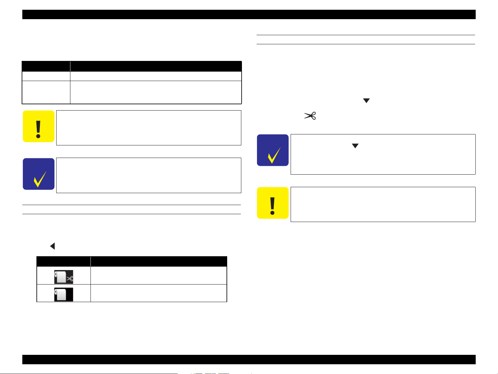
The cut method setting can be made by the control panel or the printer driver.
When setting with the control panel (for printing a status sheet or etc.)
Press button to select the cut method.
Icon Description
Roll Auto Cut On
Roll Auto Cut Off
When setting from a computer
Select “Auto Cut” in the “Paper Setting” window of the printer driver.
PRODUCT DESCRIPTION Printing Specifications 30
Confidential
Page 30

Epson Stylus Pro 7700/7710/7900/7910/9700/9710/9900/9910 Revision D
1.4 Hardware Specifications
This section provides the printer dimensions and shows the main components.
1.4.1 Dimensions and Weight
MAIN UNIT
1,218mm
667mm
OPTIONS
Pro 9900/Pro 9910: 1,295 mm
Pro 7900/Pro 7910: 787 mm
<Auto Take-up Reel Unit>
<Mounter>
267 mm
199 mm
<Color Measurement Device>
88.6 mm
71 mm
58 mm
Pro 9700/Pro 9710/Pro 9900/Pro 9910: 1,864mm
Pro 7700/Pro7710/Pro 7900/Pro 7910: 1,356mm
Figure 1-3. Dimensions (standard)
Model
Width Depth Height
Pro 9900/Pro 9910 1,864 mm 667 mm 1,218 mm Approx. 135 kg
Pro 7900/Pro 7910 1,356 mm 667 mm 1,218 mm Approx. 101 kg
Pro 9700/Pro 9710 1,864 mm 667 mm 1,218 mm Approx. 134 kg
Pro 7700/Pro 7710 1,356 mm 667 mm 1,218 mm Approx. 100 kg
Note *: Excluding the ink cartridges and paper
External Dimensions
Weight*
Model
Mounter for Pro 9900/Pro 9910 1,295 mm 199 mm 267 mm Approx. 13.4 kg
Mounter for Pro 7900/Pro 7910 787 mm 199 mm 267 mm Approx. 9.2 kg
Color Measurement Device 71 mm 88.6 mm 58 mm Approx. 0.13 kg
Auto Take-up Reel Unit – – – Approx. 6.9 kg
Figure 1-4. Dimensions
External Dimensions
Weight
Width Depth Height
PRODUCT DESCRIPTION Hardware Specifications 31
Confidential
Page 31

Epson Stylus Pro 7700/7710/7900/7910/9700/9710/9900/9910 Revision D
1.4.2 Part Names
MAIN UNIT
Adapter Holder
Ink Cover
Front Cover
Paper Basket
USB Interface Connector
Roll Paper Cover
Paper Guides
Option Interface Connector
Control Panel
Ink Cover
Manual Box
Network Interface Connector
OPTIONS
Movable Unit
Control Box
Drive Unit
Figure 1-6. Part Names (Auto Take-up Reel Unit)
Maintenance
Tank
AC Inlet
Maintenance
Tank
Figure 1-5. Part Names (Main Unit)
PRODUCT DESCRIPTION Hardware Specifications 32
Confidential
Page 32

Epson Stylus Pro 7700/7710/7900/7910/9700/9710/9900/9910 Revision D
Handle
Interface connector
to the printer
Cover
Light
Auto Take-up Reel
Unit connector
AC Inlet
Handle
Guide Rail
Mini USB interface cable
DC cable
1.4.3 Option Correspondence Table
Model Auto Take-up Reel Unit SpectroProofer 24” SpectroProofer 44”
Pro 9900/
Pro 9910
Pro 7900/
Pro 7910
Pro 9700/
Pro 9710
Pro 7700/
Pro 7710
Supported Not supported Supported
Not supported
Supported Not supported
Supported Not supported Not supported
Not supported Not supported Not supported
Lens
White calibration tile
Paper Presser
Mini USB interface connector
DC connector
Color Measurement
Device carriage
Figure 1-7. Part Names (SpectroProofer)
PRODUCT DESCRIPTION Hardware Specifications 33
Confidential
Page 33

Epson Stylus Pro 7700/7710/7900/7910/9700/9710/9900/9910 Revision D
1.5 Control Panel
BUTTONS
[Power] button
1
2
[Pause/Reset] button
11
[Ink Cover Open]
10
button
2
Epson Stylus Pro 7900/7910/9900/9910
[Paper Feed
3
(reverse)] button
[Paper Source]
9
button
[OK] button
4
[Paper Secure]
5
button
6
7
[Paper Feed
8
(forward)] button
[Menu]
button
[Paper Cut]
button
[Black Ink Change] button
Epson Stylus Pro 7700/7710/9700/9710
[Cleaning] button
PRODUCT DESCRIPTION Control Panel 34
Confidential
Page 34

Epson Stylus Pro 7700/7710/7900/7910/9700/9710/9900/9910 Revision D
BUTTONS
NOTE *1 : Epson Stylus Pro 7900/7910/9900/9910 only.
*2 : Epson Stylus Pro 7700/7710/9700/9710 only.
Button Name
Function
When pressed normally When pressed down for 3 sec. For panel setting
1[Power] Turns the printer On or Off. --- Power-off
• Displays the black ink change screen when BK ink error occurs or during
[Black Ink Change] *1
2
[Cleaning] *2 Goes to the cleaning menu. --- ---
3 [Paper Feed (reverse)]
4 [OK]
5 [Paper Secure]
6[Menu]
7[Paper Cut]
8 [Paper Feed (forward)]
idling.
• Other than above: Does not function.
• When roll paper is loaded: Feeds the paper backward.
• When roll paper is not loaded: Does not function.
• While the Paper Presser is released: Increases the power of the suction fan.
• Other than above: Does not function.
• After printing: Ejects the cut sheet.
• Sets the selected parameter in the selected item in the Menu mode. Executes
the item if the selected item is for execution only.
• During ink drying or color chart drying: Stops the operation.
• While there is no paper in the printer: Displays the paper feeding procedures
on the LCD panel.
• Other than above: Does not function.
• Locks/unlocks the paper presser when idling, waiting for the feeding trigger
or such errors occurred as:
paper released error, front cover open error, paper cut error, paper skew error,
paper error (not detected), take-up error (sensor error), borderless error, paper
out error (roll paper), paper eject error, paper size error, paper setting error.
• Other than above: Does not function.
• During printing: Goes to the PRINTER STATUS menu.
• Goes to the panel setting mode when ink drying, color chart drying,
measuring colors or when paper out error (roll paper) occurred.
• When waiting for the feeding trigger or idling: Cuts the roll paper.
• Other than above: Does not function.
• When roll paper is loaded: Feeds the paper forward.
• When roll paper is not loaded: Does not function.
• While the Paper Presser is released: Decreases the power of the suction fan.
• When cut sheet is selected and a cut sheet is loaded on the printer: Feeds the
cut sheet to the print start position.
• When a cut sheet has been fed: Ejects the cut sheet.
When roll paper is not loaded: Does not function.
• When roll paper is loaded: Feeds the roll paper forward at high speed.
• When roll paper is not loaded: Does not function.
--- ---
Increases the set
value.
Accepts the change,
---
--- ---
---
--- ---
Executes the
operation, Stores
the settings
Goes to the next
item.
Decreases the set
value.
PRODUCT DESCRIPTION Control Panel 35
Confidential
Page 35

Epson Stylus Pro 7700/7710/7900/7910/9700/9710/9900/9910 Revision D
Button Name
9 [Paper Source]
10 [Ink Cover Open]
11 [Pause/Reset]
When pressed normally When pressed down for 3 sec. For panel setting
• Changes the paper type when idling, waiting for the feeding trigger or when
such errors occurred as:
paper released error, front cover open error, paper cut error, paper skew error,
paper error (not detected), take-up error (sensor error), borderless error, paper
out error (roll paper), paper eject error, paper size error, paper setting error.
• Other than above: Does not function.
• During printing/cleaning/charging initially/changing ink: Does not function.
• Other than above: Opens the ink cover.
• When printing, idling, in the error status: Pauses the operation
• When displaying the menu screen: return to the previous screen from the
menu
• When displaying such screens as pausing, selection for opening IC Cover,
changing black ink, or cutting paper: return to the previous screen from the
sub menu
• When displaying the roll paper setting screen: return to the previous screen
from the roll paper setting screen
• Makes the printer recover from such errors as paper sensor error (barcode
detection failed), paper sensor error (wrong platen gap), cleaning error (not
enough ink), clogged nozzle error (not enough ink), cleaning error (auto head
cleaning failed).
Function
---
--- ---
---
Goes back to the
previous item.
Stops the panel
settings.
PRODUCT DESCRIPTION Control Panel 36
Confidential
Page 36

Epson Stylus Pro 7700/7710/7900/7910/9700/9710/9900/9910 Revision D
LIGHTS (LED)
Power light
A
Pause light
E
Paper Check light
B
D
Figure 1-8. LED
Ink Check light
NOTE: The figure is for Epson Stylus Pro 7900/7910/9900/9910.
Paper Secure light
C
Name Color Status Description
ON The printer power is on.
A
Power Green
B
Paper Check Orange
C
Paper Secure Orange
D
Ink Check Orange
E
Pause Green
Note "*1": Repeats turning On and Off every 500 ms. When a maintenance error is occurring, the LED
repeats ON for 100 ms and OFF for 5 seconds.
"*2": The all LEDs flash when a service call error is occurring.
Flashing*1
OFF The printer power is off.
ON
Flashing
OFF The printer is ready to print data.
ON The paper presser is released.
OFF The printer is ready to print data.
ON
Flashing*1 The installed ink cartridge is nearly expended.
OFF The printer is ready to print data.
ON
OFF The printer is ready to print data.
The printer is receiving a data or performing the poweroff sequence.
• No paper is loaded in the paper source.
• The paper setting is not correct.
• Paper is jammed.
*1
• Paper is not loaded straight.
• The installed ink cartridge is expended.
• The ink cartridge is not installed.
• The wrong ink cartridge is installed.
• The printer is in the Menu mode or pause mode.
• The printer has an error.
PRODUCT DESCRIPTION Control Panel 37
Confidential
Page 37

Epson Stylus Pro 7700/7710/7900/7910/9700/9710/9900/9910 Revision D
LCD
Normal indication
Product Name LCD Display
1
2
Epson Stylus Pro 7900/
7910/9900/9910
3
4
1
10
2
Epson Stylus Pro 7700/
7710/9700/9710
3
4
10 9
5
No. Item Description
Message Printer status, operating status, or an error message is displayed.
1
Displays the setting of "Platen Gap".
When the selected registered number in "Paper Number" is
displayed, the display is as follows:
Epson Stylus Pro 7900/7910/9900/9910's case:
This setting is not displayed.
Epson Stylus Pro 7700/7710/9700/9710's case:
Selected registered number in "Paper Number" in No 10
Platen Gap
2
8
7
6
Paper Source Selected paper type and roll paper cut settings is displayed.
9
8
7
5
3
Option Usage The options available to use are displayed as icons.
4
Ink cartridge status The current ink level in each of the nine cartridges is indicated.
5
Black Ink level The selected black ink level is indicated.
6
Waste ink level in the
7
maintenance tanks
Roll Paper Counter The remaining amount of the roll paper is displayed.
8
Roll Paper Margin
9
Paper Number
10
below is displayed.
: “NARROW” is selected.
: “WIDE” is selected.
: “WIDER” is selected.
: “WIDEST” is selected.
The free space of the maintenance tanks is indicated.
The setting made by the ROLL PAPER MARGIN menu is
indicated beside the [ ].
• 15mm: “TOP/BOTTOM 15 mm” is selected.
• 35/15mm: “TOP 35/BOTTOM 15 mm” is selected.
• 3mm: “3mm” is selected.
• 15mm: “15mm” is selected.
• Auto: “DEFAULT” is selected
When you select paper number (1 to 10) for
CUSTOM PAPER, the number you selected appears.
PRODUCT DESCRIPTION Control Panel 38
Confidential
Page 38

Epson Stylus Pro 7700/7710/7900/7910/9700/9710/9900/9910 Revision D
Error indication
BORDERLESS ERROR
LOAD A SUPPORTED PAPER
SIZE OR LOAD PAPER
CORRECTLY
12
3
Figure 1-9. LCD (Error indication)
No. Item Description
Error name An error name is displayed inverted.
1
Error icon An error icon is displayed.
2
Remedy
3
Note : When multiple errors are occurring simultaneously, the errors are indicated in the order of preset
priority. After recovering one of the error, the next error is displayed.
An explanation about the error or an instruction to recover from
the error is displayed.
LCD (Error indication with an image)
2
3 4
Figure 1-10. LCD (Error indication with an image)
No. Item Description
Error name An error name is displayed inverted.
1
Error icon An error icon is displayed.
2
Image
3
Remedy
4
Note : When multiple errors are occurring simultaneously, the errors are indicated in the order of preset
priority. After recovering one of the error, the next error is displayed.
NOT ENOUGH EMPTY SPACE
REPLACE THE
RIGHT SIDE
MAINTENANCE
TANK
An illustration that demonstrates the explanation or instruction
for the error is displayed.
An explanation about the error or an instruction to recover from
the error is displayed.
1
PRODUCT DESCRIPTION Control Panel 39
Confidential
Page 39

Epson Stylus Pro 7700/7710/7900/7910/9700/9710/9900/9910 Revision D
ICONS ON THE LCD
Remaining ink level of each color
Ink cartridge
No.
1
2
3
4
5
6
7
8
9
10
11
Epson Stylus Pro 7900/7910/9900/9910 Epson Stylus Pro 7700/7710/9700/9710
Cyan (C) Vivid Magenta (VM)
Orange (O) Cyan (C)
Yellow (Y) Photo Black (PK)
Light Cyan (LC) Yellow (Y)
Matte Black (MK) Matte Black (MK)
Photo Black (PK) ---
Vivid Magenta (VM) ---
Light Black (LK) ---
Green (G) ---
Light Light Black (LLK) ---
Vivid Light Magenta (VLM) ---
Ink remaining
Icon Ink Cartridge
There is enough ink remaining.
Ink Color
Prepare a new ink cartridge. (flashing)
The ink is expended so you cannot print.
Replace the ink cartridge with a new one.
(flashing)
Cartridge error or no cartridge has occurred.
(flashing)
Note: The figure is for Epson Stylus Pro 7900/7910/9900/9910.
Free space of the maintenance tank
Icon Free space of maintenance tank
There is enough free space in the maintenance
tank.
Prepare a new maintenance tank. (flashing)
The maintenance tank becomes full. Replace
the tank with a new one. (flashing)
PRODUCT DESCRIPTION Control Panel 40
Confidential
Page 40

Epson Stylus Pro 7700/7710/7900/7910/9700/9710/9900/9910 Revision D
1.5.1 Menu Mode Settings
Table 1-6. Menu Mode Settings List
Applied
model
Top Menu Menu Item
PLATEN GAP
PAGE LINE
PRINTER SETUP
ROLL PAPER MARGIN
PAPER SIZE CHECK
(shaded one is the default)
Settings
NARROW
STANDARD
WIDE
WIDER
WIDEST
ON Sets whether to print a page line (line for manual cutting) on roll paper or not. The page line is printed when ON
OFF
DEFAULT
TOP/BOTTOM 15mm
TOP 35/BOTTOM 15mm
15 mm
3 mm
DEFAULT
TOP/BOTTOM 15mm
TOP 35/BOTTOM 15mm
TOP 45/BOTTOM 15mm
3 mm
15 mm
ON
OFF
Explanation
Sets the platen gap (gap between the printhead and the platen).
When the “Others” is selected in the PAPER TYPE of the CUSTOM PAPER menu, the platen gap designated at
the CUSTOM PAPER menu has a priority over the setting made here. Refer to "PG Settings List" on page 49.
is selected.
The vertical line may be printed when the roll paper width that is set in the printer driver is smaller than the
width of the roll paper that is loaded in the printer. This setting is available for roll paper only.
Epson Stylus Pro 7900/7910/9900/9910
Sets the margins for roll paper.
When the Default is selected, the top margin becomes 20mm and the bottom margin becomes 15mm for the
following paper types; Premium Glossy Photo Paper(250), Premium Semigloss Photo Paper(250), and Premium
Luster Photo Paper(260).
Epson Stylus Pro 7700/7710/9700/9710
Sets the margins for roll paper.
When the Default is selected, the top margin becomes 20mm and the bottom margin becomes 15mm for the
following paper types; Premium Glossy Photo Paper(250), Premium Semigloss Photo Paper(250), and Premium
Luster Photo Paper(260).
Sets whether to detect the paper width or not.
Setting to OFF deactivates the sensor that detects the paper width when paper is loaded on the printer. This
allows the user to use paper whose width is out of the sensor’s detectable range. It means that the user can print
an image larger than the paper size. The user should know that doing so soils the platen and may cause a print
quality or any other trouble.
Pro 7900/7910/9900/9910
Pro 7700/7710/9700/9710
√√
√√
√
√
√√
PRODUCT DESCRIPTION Control Panel 41
Confidential
Page 41

Epson Stylus Pro 7700/7710/7900/7910/9700/9710/9900/9910 Revision D
Table 1-6. Menu Mode Settings List
Applied
model
Top Menu Menu Item
PAPER SKEW CHECK
REFRESH MARGIN
PRINTER SETUP
TEST PRINT
AUTO NOZZLE
PRINT NOZZLE
PATTERN
INITIALIZE SETTING EXECUTE All the settings made using the control panel are returned to their default. √√
NOZZLE CHECK PRINT
STATUS SHEET PRINT Prints information on the printer status. √√
NETWORK STATUS
JOB INFORMATION PRINT Prints a print job history report (up to 10 jobs) that is stored in the printer. √√
CUSTOM PAPER PRINT Prints the settings made in the CUSTOM PAPER menu. √√
CHECK
SHEET
(shaded one is the default)
Settings
ON
OFF
ON
OFF
ON: PERIODICALLY
OFF
OFF The printer prints a nozzle check pattern automatically at the specified timing. This setting is available only
ON: EVERY PAGE
ON: EVERY 10 PAGES
PRINT Prints information on the network status. √√
Explanation
Sets whether to detect the paper skew or not.
Setting to OFF does not carry out the detection and printing is continued even if the paper is skewed. When this
setting is set to OFF, the user should have known the risk.
This setting is not available for cut sheet because the skew detection function after printing is not provided for
cut sheet.
When this is set to ON, the top edge area of paper soiled by the previous borderless printing is automatically cut
off.
Sets the execution timing for the auto nozzle check. When the nozzle clogging is detected, the cleaning starts
automatically. You can set the number of executions for cleaning from “1.5.2 Maintenance Mode (p51)”.
when roll paper is used.
When the set number of pages is reached, the nozzle check pattern is printed on the top of the page. The counter
for counting the pages is not reset even by power-off. When this setting is changed, the counter is cleared.
Printing patterns preset in the printer is not counted except the network status sheet.
Prints a nozzle check pattern, the firmware version, paper/ink consumption, and waste ink level in the
maintenance tanks. Visually check the printout patterns for any missing lines or segments. If missing lines or
segments are observed, run a manual cleaning as necessary.
Pro 7900/7910/9900/9910
Pro 7700/7710/9700/9710
√√
√√
√√ON: EVERY JOB
√√
√√
PRODUCT DESCRIPTION Control Panel 42
Confidential
Page 42

Epson Stylus Pro 7700/7710/7900/7910/9700/9710/9900/9910 Revision D
Table 1-6. Menu Mode Settings List
Applied
model
Top Menu Menu Item
CUTTER
ADJUSTMENT
CUTTER
REPLACEMENT
POWER CLEANING EXECUTE Runs a power cleaning that is stronger than the normal cleaning. √√
MAINTENANCE
CLEAN EACH COLOR
CLOCK SETTING MM/DD/YY HH:MM Sets the date and time for the internal clock. √√
(shaded one is the default)
Settings
Epson Stylus Pro 7900/7910/9900/9910
EXECUTE
-0.3mm to +3.0mm
EXECUTE Runs a cutter replacement sequence. √√
C/VM
PK(MK)/LK
O/G
LLK/Y
VLM/LC
C/VM
Y/BK
MK
Adjusts the built-in cutter position.
A cutter position adjustment pattern is printed. Examine the printout patterns and select the number for the best
pattern.
Epson Stylus Pro 7700/7710/9700/9710
Fine-adjusts the cutter position. You can adjust the cutter position by 0.2 mm.
Epson Stylus Pro 7900/7910/9900/9910
Runs a cleaning for the specified nozzle columns.
Epson Stylus Pro 7700/7710/9700/9710
Runs a cleaning for the specified nozzle columns.
Explanation
Pro 7900/7910/9900/9910
Pro 7700/7710/9700/9710
√
√
√
√
PRODUCT DESCRIPTION Control Panel 43
Confidential
Page 43

Epson Stylus Pro 7700/7710/7900/7910/9700/9710/9900/9910 Revision D
Table 1-6. Menu Mode Settings List
Applied
model
Top Menu Menu Item
VERSION
PRINTABLE PAGES (ink color) nnnnnnn PAGES Displays the number of pages printable with the installed ink cartridges. √√
INK LEVEL (ink color) nn% Displays the ink level in the installed ink cartridges. √√
MAINTENANCE TANK
PRINTER STATUS
JOB HISTORY
TOTAL PRINTS nnnnnn PAGES Displays the total printed pages using 6-digit decimal number. √√
PRINTER STATUS EDM STATUS
(shaded one is the default)
Settings
HW0xxxx-xx.xx.IBCC or
HN0xxxx-xx.xx.IBCC
LEFT nn%
RIGHT nn%
No.0 to No.9
Ink xxxxx.xml
Paper xxx.x cm2
NOT STARTED, ENABLED,
DISABLED
LAST UPLOADED
MM/DD/YY HH:MM GMT
(NOT UPLOADED)
Explanation
Pro 7900/7910/9900/9910
Pro 7700/7710/9700/9710
Displays the firmware version. Refer to "Firmware version information" on page 50. √√
Displays the waste ink level in the installed maintenance tanks. √√
Job No.
Displays the job number that is stored in the printer. The latest job number is 0 (zero).
The amount of ink consumed
Displays the amount of ink consumed for each job.
The amount of paper consumed
Displays the total area of paper used for each job.
Displays the EDM status. √√
√√
√√
√√
PRODUCT DESCRIPTION Control Panel 44
Confidential
Page 44

Epson Stylus Pro 7700/7710/7900/7910/9700/9710/9900/9910 Revision D
Table 1-6. Menu Mode Settings List
Applied
model
Top Menu Menu Item
ROLL PAPER
REMAINING
PAPER SETUP
PAPER TYPE
(shaded one is the default)
REMAINING PPR SETUP
Settings
Make settings for the remaining roll paper.
OFF: Disables the roll paper remaining amount count function.
ON: Displays the roll paper remaining amount on the LCD. Each time a print job is finished, a barcode that
includes information on PAPER TYPE, PAPER LENGTH, and ROLL_LENGTH_ALERT settings is
printed.
When roll paper is replaced with a new one, the printer reads the barcode and automatically applies the
read settings for the new roll paper.
ROLL PAPER LENGTH You can make these settings only when REMAINING PPR SETUP above is set to ON. The printer
ROLL LENGTH ALERT √√
Photo Paper
Proofing Paper
Fine Art Paper
Matte Paper
Plain paper
Others
CUSTOM PAPER
NO PAPER SELECTED
Photo Paper
Matte Paper
Plain paper
Others
CUSTOM PAPER
NO PAPER SELECTED
Sets roll paper length, and the remaining length of roll paper to be alerted when the set amount is reached.
The printer displays the roll paper remaining amount and the alert for shortage of the remaining on the LCD.
Epson Stylus Pro 7900/7910/9900/9910
Sets the paper type loaded on the printer.
Epson Stylus Pro 7700/7710/9700/9710
Sets the paper type loaded on the printer.
Explanation
Pro 7900/7910/9900/9910
√√
√√
√
√
Pro 7700/7710/9700/9710
PRODUCT DESCRIPTION Control Panel 45
Confidential
Page 45

Epson Stylus Pro 7700/7710/7900/7910/9700/9710/9900/9910 Revision D
Table 1-6. Menu Mode Settings List
Applied
model
Top Menu Menu Item
CUSTOM PAPER PAPER NO.1 - 10
PLATEN GAP
THICKNESS
PATTERN
PAPER SETUP
PAPER FEED ADJUST
DRYING TIME
PAPER SUCTION
SET ROLL PAPER
TENSION
REMOVE SKEW
(shaded one is the default)
Settings
NARROW
STANDARD
WIDE
WIDER
WIDEST
PRINT Prints a pattern for checking the thickness of the loaded paper. √√
0.00% Adjusts the paper feed line pitch.
-0.70% to +0.70%
0.0 SEC
0.0 SEC to 10.0 SEC
STANDARD
-1 to -4
NORMAL
HIGHER
ON
OFF
Explanation
Pro 7900/7910/9900/9910
Pro 7700/7710/9700/9710
You can select a number (between 1 to 10) to register the settings (such as Paper Type, Platen Gap, Thickness
Pattern, Paper Feed Adjust, Drying Time, Paper Suction) or to recall these settings you have made. The number
you select here is displayed on the LCD panel.
Adjusts the platen gap (gap between the printhead and paper surface) according to the paper thickness.
STANDARD: use this setting under normal conditions
NARROW: select this when using thin paper.
WIDE, WIDER: select this when smudges or blurring appear due to an excess pressure on the paper.
WIDEST: select this when using heavy paper.
The larger the value is, the more the possibility to cause white bands on printout image.
The smaller the value is, the more the possibility to cause black bands on printout image.
Sets a time period to pause the carriage movement for drying the printed surface. Depending on paper type and
density, drying ink may take longer. Check the result and set longer time period in such case.
Sets the power level of the suction fan. √√
When using a cloth or thin paper or when winkles appear in the paper during printing, select
“HIGH” or “HIGHER”.
Sets whether to perform this operation to reduce the paper skew or not. √√
√√
√√
√√
√√
√HIGH
PRODUCT DESCRIPTION Control Panel 46
Confidential
Page 46

Epson Stylus Pro 7700/7710/7900/7910/9700/9710/9900/9910 Revision D
Table 1-6. Menu Mode Settings List
Applied
model
Top Menu Menu Item
PAPER THICKNESS
HEAD ALIGNMENT
NETWORK SETUP
IP ADDRESS
NETWORK SETUP
IP, SM, DG SETTING
INIT NETWORK
ALIGNMENT
SETTING
BONJOUR
SETTING
(shaded one is the default)
ADDRESS
SUBNET
MASK
DEFAULT
GATEWAY
Settings
SELECT PAPER TYPE Sets thickness of paper to be used.
SELECT THICKNESS
AUTO Sets whether to carry out the head alignment adjustment automatically or manually.
MANUAL
DISABLE
ENABLE
AUTO
PANEL
IP
000.000.000.000 -
172.024.011.031
- 255.255.255.255
000.000.000.000 -
255.255.192.168
- 255.255.255.255
000.000.000.000 -
255.024.011.001
- 255.255.255.255
ON
OFF
EXECUTE Returns the network settings to their default. √√
• When Epson paper is used, select the paper type.
• When not Epson paper is selected, enter the thickness of the selected paper.
AUTO:
The adjustment is carried out automatically after the adjustment pattern is printed.
MANUAL:
Select this to carry out the adjustment manually (visually check the patterns and enter selected values) after
printing the adjustment pattern.
Enables or disables the network settings.
The NETWORK SETUP menu items appear on the LCD only when this is set to ENABLE.
Sets whether to set the IP address automatically or manually.
When the PANEL is selected, the IP, SM, DG SETTING menu is enabled to enter the address manually.
Sets the IP address, subnet mask, and default gateway manually.
Enables or disables the BONJOUR. √√
Explanation
Pro 7900/7910/9900/9910
Pro 7700/7710/9700/9710
√√
√√
√√
√√
√√
√√
√√
PRODUCT DESCRIPTION Control Panel 47
Confidential
Page 47

Epson Stylus Pro 7700/7710/7900/7910/9700/9710/9900/9910 Revision D
Table 1-6. Menu Mode Settings List
Applied
model
Top Menu Menu Item
OPTIONS SETUP
SpectroProofer
TAKE UP REEL TAKE UP REEL VERSION Displays the version of Auto Take-up Reel Unit. √√
(shaded one is the default)
Settings
STATUS INFORMATION
DEVICE ALIGNMENT
Explanation
Displays the status of each item of SpectroProofer, such as the version of SpectroProofer, the product numbers
of the white calibration tiles, the temperature of Color Measurement Device (ILS20EP), ambient air
temperature, and the color of the backing.
Performs the setup for SpectroProofer installed.
Pro 7900/7910/9900/9910
Pro 7700/7710/9700/9710
√
PRODUCT DESCRIPTION Control Panel 48
Confidential
Page 48

Epson Stylus Pro 7700/7710/7900/7910/9700/9710/9900/9910 Revision D
PG Settings List
The table below shows the actual platen gap amount specified by the printer driver
or the control panel.
Table 1-7. PG Settings List
Paper
Thickness
Sensor
0.4 mm or
lower
Paper Thickness
Setting by Driver
No setting
0.0 to 0.8mm
0.9mm to 1.5mm -- -- 2.6
Menu Setting
NARROW
STANDARD
WIDE
WIDER
WIDEST
Media Table or Printer
Driver PG Setting
Narrow 0.8
Standard 0.8
Wide 1.2
Wider 1.6
Narrow 0.8
Standard 1.2
Wide 1.6
Wider 2.1
Narrow 1.2
Standard 1.6
Wide 2.1
Wider 2.6
Narrow 1.6
Standard 2.1
Wide 2.6
Wider 2.6
Narrow 2.1
Standard 2.6
Wide 2.6
Wider 2.6
PG Values
(mm)
Paper
Thickness
Sensor
0.5mm to
0.8mm
0.9mm to
2.1mm
Table 1-7. PG Settings List
Paper Thickness
Setting by Driver
No setting
0.0 to 0.8mm
0.9mm to 1.5mm -- -- 2.6
-- -- -- 2.6
Menu Setting
NARROW
STANDARD
WIDE
WIDER
WIDEST
Media Table or Printer
Driver PG Setting
Narrow 0.8
Standard 0.8
Wide 1.2
Wider 1.6
Narrow 0.8
Standard 1.2
Wide 1.6
Wider 2.1
Narrow 1.2
Standard 1.6
Wide 2.1
Wider 2.6
Narrow 1.6
Standard 2.1
Wide 2.6
Wider 2.6
Narrow 2.1
Standard 2.6
Wide 2.6
Wider 2.6
PG Values
(mm)
PRODUCT DESCRIPTION Control Panel 49
Confidential
Page 49

Epson Stylus Pro 7700/7710/7900/7910/9700/9710/9900/9910 Revision D
Firmware version information
The table below explains the firmware version information printed by selecting the
VERSION in the PRINTER STATUS menu.
<Format>
Epson Stylus Pro 9900/9910: HW0XXXX-xx.xx.IBCC
Epson Stylus Pro 7900/7910: HN0XXXX-xx.xx.IBCC
Epson Stylus Pro 9700/9710: KW0XXXX-xx.xx.IBCC
Epson Stylus Pro 7700/7710: KN0XXXX-xx.xx.IBCC
Table 1-8. Firmware Version Information
Item Explanation
The code assigned to this printer.
Epson Stylus Pro 9900/9910: HW
**0
XXXX Indicates the firmware version installed on the printer.
xx.xx Indicates the network firmware version.
I "A" is indicated for this product.
B "0" is indicated for this product.
C
Epson Stylus Pro 7900/7910: HN
Epson Stylus Pro 9700/9710: KW
Epson Stylus Pro 7700/7710: KN
"0" (zero) is assigned to a special version of printer.
A hexadecimal number (00H-FFH) appears to indicate the specified custom
number that registers special operation setting. When no custom operation is
"00"
specified,
appears.
PRODUCT DESCRIPTION Control Panel 50
Confidential
Page 50

Epson Stylus Pro 7700/7710/7900/7910/9700/9710/9900/9910 Revision D
1.5.2 Maintenance Mode
The maintenance mode allows you to change the environmental settings such as
language and unit settings to be displayed, or to return the all settings to their default.
The user can also access this mode.
HOW TO START & QUIT
1. While holding down the [Pause/Reset] button, turn the printer on.
2. Turn the printer off to quit the maintenance mode.
MAINTENANCE MODE MENU LIST
Settings
Menu Item
LANGUAGE
LENGTH UNIT
TEMPERATURE
UNIT
ROLL PAPER
TENSION
SS CLEANING
DEFAULT PANEL
AUTO CLEANING
TIMES *
CUSTOM
Note : If this menu is not displayed in Epson Stylus Pro 7900/7910/9900/9910, update the firmware to the
latest. This menu is added and the setting becomes available after updating.
(shaded one is the
default)
JAPANESE
ENGLISH
FRENCH
GERMAN
ITALIAN
PORTUGUE
SPANISH
DUTCH
KOREAN
CHINESE
METRIC
FEET/INCH
°C
F
1
2
3
4
5
EXECUTE
EXECUTE
1
2
3
0 - 255
Explanation
Selects the language used for the control panel
display.
Selects the unit of length to be used for
various length information.
Selects the unit of temperature displayed on
the LCD panel.
Specifies the maximum value of Roll Paper
Tension.
1: Low tension
5: High tension
Runs a supersonic head cleaning.
Returns the all settings made by the control
panel to their default.
Sets the number of cleanings when nozzle
clogging is detected at auto nozzle check.
Stores custom settings.
PRODUCT DESCRIPTION Control Panel 51
Confidential
Page 51

Epson Stylus Pro 7700/7710/7900/7910/9700/9710/9900/9910 Revision D
1.5.3 Serviceman Mode
The Serviceman Mode is intended to be used by a service personnel for servicing the printer.
HOW TO START & QUIT
1. Turn the printer on by pressing the [OK], [Paper Feed/Down], and [Menu/Right] buttons.
2. Turn the printer off to quit the Serviceman Mode.
SERVICEMAN MODE MENU LIST
Epson Stylus Pro 7900/7910/9900/9910
Menu Explanation
Test Version F/W Displays the F/W version.
FAN Paper (Duty) Checks the operation of each fan.
Paper 1
Paper 2
Paper 3
Error History ... Displays the history of errors in the reverse chronological order.
PRODUCT DESCRIPTION Control Panel 52
Confidential
Page 52

Epson Stylus Pro 7700/7710/7900/7910/9700/9710/9900/9910 Revision D
Menu Explanation
Mecha Adjustment Paper Adjusts the Paper Thickness Sensor.
Rear AD Adjusts the AD value of the Rear Sensor (PE Sensor).
Selector Check Checks the operation of the ink selector.
APG Check Checks the operation of the APG.
PF Ageing Variable Mode Runs the PF Ageing.
Ageing 400
Ageing 12
CR Ageing Runs the CR Ageing.
Cleaning PG Adjustment Runs the cleaning PG adjustment.
Check Runs the cleaning PG check.
Decomp Decompress the Pressurizing Pump.
Mk Nozzle/Alignment Output Pattern Runs the check function of nozzle and alignment. From pattern printing to
Output Alignment
Cleaning CL1
cleaning can be executed from this menu.
PRODUCT DESCRIPTION Control Panel 53
Confidential
Page 53

Epson Stylus Pro 7700/7710/7900/7910/9700/9710/9900/9910 Revision D
Menu Explanation
Mecha Adjustment Mk Nozzle/Alignment Cleaning CL2 Runs the check function of nozzle and alignment. From pattern printing to
Cleaning CL3
Init.Fill
SSCL
A/B (C/M) CL1
CL2
CL3
CL4
C/D (Bk/Lk) CL1
CL2
CL3
CL4
E/F (Or/Gr) CL1
CL2
CL3
CL4
G/H (LLk/Y) CL1
CL2
CL3
CL4
I/J (Lm/Lc) CL1
CL2
CL3
CL4
Pk Nozzle/Alignment Output Pattern
Output Alignment
Cleaning CL1
Cleaning CL2
cleaning can be executed from this menu.
PRODUCT DESCRIPTION Control Panel 54
Confidential
Page 54

Epson Stylus Pro 7700/7710/7900/7910/9700/9710/9900/9910 Revision D
Menu Explanation
Mecha Adjustment Pk Nozzle/Alignment Cleaning CL3 Runs the check function of nozzle and alignment. From pattern printing to
Init.Fill
SSCL
A/B (C/M) CL1
CL2
CL3
CL4
C/D (Bk/Lk) CL1
CL2
CL3
CL4
E/F (Or/Gr) CL1
CL2
CL3
CL4
G/H (LLk/Y) > CL1
CL2
CL3
CL4
I/J (Lm/Lc) CL1
CL2
CL3
CL4
IM Sensor Gap Adjusts the gap of the Ink Mark Sensor.
FAN Operates the Suction Fan.
Temporary PG Unlocks the carriage lock and caps the Printhead.
PF Head Slant Adjusts the slant of the Printhead to the PF.
CR Head Slant Adjusts the slant of the Printhead to the CR.
cleaning can be executed from this menu.
PRODUCT DESCRIPTION Control Panel 55
Confidential
Page 55

Epson Stylus Pro 7700/7710/7900/7910/9700/9710/9900/9910 Revision D
Menu Explanation
Mecha Adjustment PG Adj. Adjusts the platen gap.
CR Scale Moves the carriage unit by 10 pass, and displays the measured value.
CR Active Damper ALL Executes the CR active dumper adjustment.
240 cps
300 cps
Hybrid
AID Check Runs the AID check.
IM Sensor Adjusts the sensitivity of the Ink Mark Sensor.
Gap Adj. Auto Uni-D Runs the gap adjustment.
Auto Bi-D
Feed Adj Runs the band feed adjustment.
Cutter Checks the cutter operation.
TBS Pos Runs the TBS adjustment.
Pad Position Adjusts the pad position.
Measurement Mecha Executes a measurement of the mechanism.
Ink System Executes a measurement of the ink system.
Print Adj. Variable Prints the adjustment variables.
Board Paper Check Executes a Board Paper feeding check.
LCD RGB Check Red Checks the operation of the LCD.
Green
Blue
Panel Check Button Checks the operation of the Buttons and the LEDs.
LED
Counter Check Checks various counters.
Counter Clear Resets various counters.
PRODUCT DESCRIPTION Control Panel 56
Confidential
Page 56

Epson Stylus Pro 7700/7710/7900/7910/9700/9710/9900/9910 Revision D
Menu Explanation
Maintenance Tube Exchange Exchanges an ink tube.
Wiper Exchange Exchanges the wiper.
Pump Exchange Exchanges the pump.
Press Pump Exchange Exchanges the pressurizing pump.
Selector Exchange Exchanges the ink selector.
I/H Exchange Exchanges the ink holder.
Head Exchange Exchanges the Printhead.
Cleaning Std. CL1 Runs CL1.
Std. CL2 Runs CL2.
Std. CL3 Runs CL3.
Init.Fill Executes the initial ink charge.
SSCL Runs SSCL
A/B (C/M) CL1 Runs various cleanings for the nozzle row A/B.
CL2
CL3
CL4
C/D (Bk/Lk) CL1 Runs various cleanings for the nozzle row C/D.
CL2
CL3
CL4
E/F (Or/Gr) CL1 Runs various cleanings for the nozzle row E/F.
CL2
CL3
CL4
G/H (LLk/Y) > CL1 Runs various cleanings for the nozzle row G/H.
CL2
CL3
CL4
PRODUCT DESCRIPTION Control Panel 57
Confidential
Page 57

Epson Stylus Pro 9900/7900 Revision B
Menu Explanation
Cleaning I/J (Lm/Lc) CL1 Runs various cleanings for the nozzle row I/J.
CL2
CL3
CL4
ServicemanCL Discharges the ink and runs cleaning of the ink path. (p380)
Parameter Update InkParateter Sets/resets the ink initial charge flag.
RTC Configures the initializing date for the RTC.
Display Displays the NVRAM value of the specified address.
Life CR PG Configures the durability settings of the mechanism and the printhead.
H to F Speed
F to H Speed
Page Size
Fan
Life Count
PF Feed Amount 1
Feed Speed 1
Feed Amount 2
Feed Speed 2
Wait
DD Nip
Fan
Life Count
PRODUCT DESCRIPTION Control Panel 58
Confidential
Page 58

Epson Stylus Pro 9900/7900 Revision B
Menu Explanation
Life RR Rotation (mm) Configures the durability settings of the mechanism and the printhead.
Speed
Release planet
Waiting period (sec.)
Life Count
Tension Switching 1
Switching 2
Waiting period (sec.)
Life Count
Driven roller Switching
Waiting period 1 (sec.)
Waiting period 2 (sec.)
Life Count
APG PG
Wait
Life Count
Cutter Length
Return Length
Speed
Return Speed
Wait1
Wait2
Fan1
Fan2
Life Count
PRODUCT DESCRIPTION Control Panel 59
Confidential
Page 59

Epson Stylus Pro 9900/7900 Revision B
Menu Explanation
Life Take up Take up Reel Rotation (mm) Configures the durability settings of the mechanism and the printhead.
Winding Speed
Waiting period (sec.)
Duration times
Colorimetric Carrier CW Speed
CCW Speed
Movement Distance (mm)
Waiting period (sec.)
Duration times
Paper Pressing Plate Waiting period (sec.)
Duration times
Carrir + Plate CW Speed
CCW Speed
Movement Distance (mm)
Waiting period (sec.)
Duration times
Display Count Display Count
PRODUCT DESCRIPTION Control Panel 60
Confidential
Page 60

Epson Stylus Pro 9900/7900 Revision B
Epson Stylus Pro 7700/7710/9700/9710
Menu Explanation
Test Version F/W Displays the F/W version.
FAN Paper (Duty) Checks the operation of each fan.
Paper 1
Paper 2
Paper 3
Error History ... Displays the history of errors in the reverse chronological order.
Mecha Adjustment Paper Adjusts the Paper Thickness Sensor.
Rear AD Adjusts the AD value of the Rear Sensor (PE Sensor).
Selector Check Checks the operation of the ink selector.
APG Check Checks the operation of the APG.
PF Ageing Variable Mode Runs the PF Ageing.
Ageing 400
Ageing 12
CR Ageing Runs the CR Ageing.
Cleaning PG Adjustment Runs the cleaning PG adjustment.
Check Runs the cleaning PG check.
Decomp Decompress the Pressurizing Pump.
PRODUCT DESCRIPTION Control Panel 61
Confidential
Page 61

Epson Stylus Pro 9900/7900 Revision B
Menu Explanation
Mecha Adjustment Nozzle/Alignment Output Pattern Runs the check function of nozzle and alignment. From pattern printing to
Output Alignment
Cleaning CL1
Cleaning CL2
Cleaning CL3
Init.Fill
SSCL
A/B/I/J (C/M/M/C) CL1
CL2
CL3
CL4
C/D/G/H (Y/Pk/Pk/Y) CL1
CL2
CL3
CL4
E/F (Mk/Mk) CL1
CL2
CL3
CL4
IM Sensor Gap Adjusts the gap of the Ink Mark Sensor.
FAN Operates the Suction Fan.
Temporary PG Unlocks the carriage lock and caps the Printhead.
PF Head Slant Adjusts the slant of the Printhead to the PF.
CR Head Slant Adjusts the slant of the Printhead to the CR.
PG Adj. Adjusts the platen gap.
CR Scale Moves the carriage unit by 10 pass, and displays the measured value.
cleaning can be executed from this menu.
PRODUCT DESCRIPTION Control Panel 62
Confidential
Page 62

Epson Stylus Pro 9900/7900 Revision B
Menu Explanation
Mecha Adjustment CR Active Damper ALL Executes the CR active dumper adjustment.
240 cps
300 cps
Hybrid
AID Check Runs the AID check.
IM Sensor Adjusts the sensitivity of the Ink Mark Sensor.
Gap Adj. Auto Uni-D Runs the gap adjustment.
Auto Bi-D
Feed Adj Runs the band feed adjustment.
Cutter Checks the cutter operation.
TBS Pos Runs the TBS adjustment.
Pad Position Adjusts the pad position.
Measurement Mecha Executes a measurement of the mechanism.
Ink System Executes a measurement of the ink system.
Print Adj. Variable Prints the adjustment variables.
Board Paper Check Executes a Board Paper feeding check.
LCD RGB Check Red Checks the operation of the LCD.
Green
Blue
Panel Check Button Checks the operation of the Buttons and the LEDs.
LED
Counter Check Checks various counters.
Counter Clear Resets various counters.
PRODUCT DESCRIPTION Control Panel 63
Confidential
Page 63

Epson Stylus Pro 9900/7900 Revision B
Menu Explanation
Maintenance Tube Exchange Exchanges an ink tube.
Wiper Exchange Exchanges the wiper.
Pump Exchange Exchanges the pump.
Press Pump Exchange Exchanges the pressurizing pump.
I/H Exchange Exchanges the ink holder.
Head Exchange Exchanges the Printhead.
Cleaning Std. CL1 Runs CL1.
Std. CL2 Runs CL2.
Std. CL3 Runs CL3.
Init.Fill Executes the initial ink charge.
SSCL Runs SSCL
A/B/I/J (C/M/M/C) CL1 Runs various cleanings for the nozzle row A/B.
CL2
CL3
CL4
C/D/G/H (Y/Pk/Pk/Y) CL1 Runs various cleanings for the nozzle row C/D.
CL2
CL3
CL4
E/F (Mk/Mk) CL1 Runs various cleanings for the nozzle row E/F.
CL2
CL3
CL4
I/J (Lm/Lc) CL1 Runs various cleanings for the nozzle row I/J.
CL2
CL3
CL4
ServicemanCL Discharges the ink and runs cleaning of the ink path. (p380)
PRODUCT DESCRIPTION Control Panel 64
Confidential
Page 64

Epson Stylus Pro 9900/7900 Revision B
Menu Explanation
Parameter Update InkParateter Sets/resets the ink initial charge flag.
RTC Configures the initializing date for the RTC.
Display Displays the NVRAM value of the specified address.
Life CR PG Configures the durability settings of the mechanism and the printhead.
H to F Speed
F to H Speed
Page Size
Fan
Life Count
PF Feed Amount 1
Feed Speed 1
Feed Amount 2
Feed Speed 2
Wait
DD Nip
Fan
Life Count
RR Rotation (mm)
Speed
Release planet
Waiting period (sec.)
Life Count
Driven roller Switching
Waiting period 1 (sec.)
Waiting period 2 (sec.)
Life Count
APG PG
Wait
Life Count
PRODUCT DESCRIPTION Control Panel 65
Confidential
Page 65

Epson Stylus Pro 9900/7900 Revision B
Menu Explanation
Life Cutter Length Configures the durability settings of the mechanism and the printhead.
Return Length
Speed
Return Speed
Wait1
Wait2
Fan1
Fan2
Life Count
Take up Take up Reel Rotation (mm)
Winding Speed
Waiting period (sec.)
Duration times
Display Count Display Count
PRODUCT DESCRIPTION Control Panel 66
Confidential
Page 66

OPERATING PRINCIPLES
CHAPTER
2
Confidential
Page 67

Epson Stylus Pro 7700/7710/7900/7910/9700/9710/9900/9910 Revision D
2.1 Main Body
2.1.1 Housing
7
6
Diagram Name Description
Operations and configurations of the printer
1 Control Panel
IC Cover Unlock
2
Solenoid R
3 IC Cover Sensor Assy R Detects the Open/Closed status of the IC Cover R.
1
4 Front Cover Sensor R Detects the Open/Closed status of the Front Cover.
5 Front Cover Sensor L Detects the Open/Closed status of the Front Cover.
IC Cover Unlock
6
Solenoid L *
IC Cover Sensor Assy L
7
*
Note : Epson Stylus Pro 7900/7910/9900/9910 only.
Displays the printer’s status, and each value for the
settings on LCD display.
Indicates the printer’s (error) statuses with LEDs.
Unlocks the IC Cover R.
Unlocks the IC Cover L.
Detects the Open/Closed status of the IC Cover L.
5
4
3
2
Figure 2-1. Housing
OPERATING PRINCIPLES Main Body 68
Confidential
Page 68

Epson Stylus Pro 7700/7710/7900/7910/9700/9710/9900/9910 Revision D
2.1.2 Electric Circuit Components
2
3
1
Figure 2-2. Electric Circuit Components
Diagram Name Description
Relays the connection between the Main Board Assy
1 Head Board Assy L
4
5
2 Sub Board Assy; C
6
3 Sub Board Assy
7
4 Power Supply Board Assy
8
5 Main Board Assy
6 Sub Board Assy; B
7AID Board
8 Head Board Assy R
and electric parts/components of every kind. See
"Block Wiring Diagram" (p. 393) for specific
connections to the concerning parts/components.
Relays the connection between the Main Board Assy
and electric parts/components of every kind. See
"Block Wiring Diagram" (p. 393) for specific
connections to the concerning parts/components.
Relays the connection between the Main Board Assy
and electric parts/components of every kind. See
"Block Wiring Diagram" (p. 393) for specific
connections to the concerning parts/components.
Generates the DC voltage for this printer from the AC
power supply.
Communicates with the computer.
Processes received data.
Controls the printer mechanism.
Stores the correction values and various counters.
Generates the voltages for the logic system from the
voltage of 42V supplied from the Power Supply
Board Assy.
Relays the connection between the Main Board Assy
and electric parts/components of every kind. See
"Block Wiring Diagram" (p. 393) for specific
connections to the concerning parts/components.
The board to perform the AID function which detects
dot missing automatically.
Relays the connection between the Main Board Assy
and electric parts/components of every kind. See
"Block Wiring Diagram" (p. 393) for specific
connections to the concerning parts/components.
OPERATING PRINCIPLES Main Body 69
Confidential
Page 69

Epson Stylus Pro 7700/7710/7900/7910/9700/9710/9900/9910 Revision D
2.1.3 Carriage Mechanism
CR Scale
5
1
Cap Motor
2
Diagram Name Description
1 CR Encoder
2 CR HP Sensor Detects the home position of the Carriage Unit.
3 CR Lock
4 CR Belt
5 CR Motor The motor to drive the Carriage Unit.
Detects the scale patterns to control the position of the
Carriage Unit.
Locks the Carriage Unit. It is driven by the Cap Motor.
(See p. 74.)
Conveys the drive force of the CR Motor to the
Carriage Unit.
3
4
Figure 2-3. Carriage Mechanism
OPERATING PRINCIPLES Main Body 70
Confidential
Page 70

Epson Stylus Pro 7700/7710/7900/7910/9700/9710/9900/9910 Revision D
2.1.4 APG Mechanism
1
Diagram Name Description
1 PG HP Sensor Detects the origin position of the platen gap.
2
3
2 APG Encoder Sensor
3APG Motor
Detects patterns of the scale attached on the motor to
control the rotation of the APG Motor.
The motor to move the Carriage Unit automatically so
as to change the platen gap.
Figure 2-4. Paper Feed Mechanism
OPERATING PRINCIPLES Main Body 71
Confidential
Page 71

Epson Stylus Pro 7700/7710/7900/7910/9700/9710/9900/9910 Revision D
2.1.5 Paper Feed Mechanism
2
3
1
14
13
12
11
Figure 2-5. Paper Feed Mechanism
10
Diagram Name Description
1 PF Encoder
4
5
6
7
Roller Release HP
2
Sensor
Driven Roller Release
3
Motor Assy
Driven Roller Release
4
Motor Encoder
5 PE Sensor
6 Paper Thickness Sensor
8
7 Rewind Motor
8 Rewind Motor Encoder
9
9 PW Sensor
10 Cutter Sensor Detects the origin position of the cutter.
11 Suction Fans
12 Cutter Encoder
13 Cutter Motor
14 PF Motor The motor to drive the Feed Roller.
Detects the PF Scale patterns to control the paper
feeding (operation of the PF Motor).
Detects the position (Contact/Separate status) of the
driven roller.
Drives the driven roller. A DC motor with an encoder
scale mounted on it is employed.
Detects patterns of the scale attached on the motor to
control the rotation of the Driven Roller Release Motor
Assy.
A reflective photo interrupter to detect the presence of
paper.
Detects the thickness of paper being inserted into the
printer.
Takes up the slack of the roll paper when the motor
rotates normally, and rewinds the roll paper when it
rotates reversely. A DC motor with an encoder scale
mounted on it is employed.
Detects patterns of the scale attached on the motor to
control the rotation of the Rewind Motor.
Detects the width of paper on the platen. It is a
reflective photo interrupter and detects the difference of
the amount of reflection between paper (white) and the
platen (black).
Suck paper to the platen so as to stabilize the position of
paper when printing. Three fans are mounted for Epson
Stylus Pro 9700/9710/9900/9910, and two fans for
Epson Stylus Pro 7700/7710/7900/7910
Detects patterns of the scale attached on the motor to
control the rotation of the Cutter Motor.
Drives the cutter. A DC motor with an encoder scale
mounted on it is employed.
OPERATING PRINCIPLES Main Body 72
Confidential
Page 72

Epson Stylus Pro 7700/7710/7900/7910/9700/9710/9900/9910 Revision D
2.1.6 Ink System
5
Diagram Name Description
The sensor to execute the functions below.
Auto Bi-D adjustment (pattern reading)
1 Ink Mark Sensor
2 Printhead
1
3 Ink Selector Motor *1 Drives the Ink Selector.
4 Ink Selector Sensor *1
4
2
3
5 Ink Cartridges *2 The cartridges storing ink. They mount CSIC.
Note *1 : Epson Stylus Pro 7900/7910/9900/9910 only.
*2: Epson Stylus Pro 7700/7710/9700/9710: Only the ink cartridges on the right are
used.
Auto Uni-D adjustment (pattern reading)
Remaining roll paper detection (remaining block
pattern reading)
Nozzle per row: 360 nozzles
Rows: 10
• Epson Stylus Pro 7900/7910/9900/9910: Photo
Black and Matte Black use one row in common.
• Epson Stylus Pro 7700/7710/9700/9710: Photo
Black and Matte Black use their own rows.
Detects the position of the Ink Selector (selected ink
color)
5
Figure 2-6. Ink System
OPERATING PRINCIPLES Main Body 73
Confidential
Page 73

Epson Stylus Pro 7700/7710/7900/7910/9700/9710/9900/9910 Revision D
INK SYSTEM UNIT
Diagram Name Description
1 Cap HP Sensor Detects the origin position of the Cap.
5
4
3
2
1
6
7
8
2Wiper
3 Flushing Box
4 Wiper Motor Encoder
5 Wiper HP Sensor Detects the origin position of the Wiper.
6Wiper Motor
7 Cap Motor Encoder
9
8 Cap Motor Drives the Cap and the CR Lock.
9 Pump Motor
10 Valve HP Selector Detects the origin position of the valve.
10
11 Cap
Cleans the nozzle surface of the Printhead. It is driven
by the Wiper Motor.
The box to receive the flushed ink. It is driven by the
Wiper Motor.
Detects patterns of the scale attached on the motor to
control the rotation of the Wiper Motor.
Slides the Wiper and the Flushing Box. A DC motor
with an encoder scale mounted on it is employed.
Detects patterns of the scale attached on the motor to
control the rotation of the Cap Motor.
Drives the pump to suck ink. A DC motor with an
encoder scale mounted on it is employed.
Caps the Printhead to protect the nozzle surface. It is
driven by the Cap Motor.
11
Figure 2-7. Ink System Unit
OPERATING PRINCIPLES Main Body 74
Confidential
Page 74

Epson Stylus Pro 7700/7710/7900/7910/9700/9710/9900/9910 Revision D
PRESSURIZING UNIT
Diagram Name Description
A transmissive photo interrupter to detect the
1 Pressure Sensor
1
2
3
Pressurizing Pump
Motor
Pressurizing Pump
Motor Encoder
pressurizing status. It detects the status of the actuator
which operates when the pressure reaches up to the
specified amount.
Supplies air to pressurize the ink pack. A DC motor
with an encoder scale mounted on it is employed.
Detects patterns of the scale attached on the motor to
control the rotation of the Pressurizing Pump Motor.
3
2
Figure 2-8. Pressurizing Unit
OPERATING PRINCIPLES Main Body 75
Confidential
Page 75

Epson Stylus Pro 7700/7710/7900/7910/9700/9710/9900/9910 Revision D
2.2 Options
2.2.1 Auto Take-up Reel
6
5
Diagram Name Description
1 Power Supply Board
2 Main Board Controls the Auto Take-up Reel.
3 Auto Take-up Encoder
1
4 Auto Take-up Motor
5 Slack Sensor
2
6 Control Panel
Generates the DC voltage for the Auto Take-up Reel
from the AC power supply.
Detects patterns of the scale attached on the motor to
control the rotation of the Auto Take-up Motor.
A motor to wind paper. A DC motor with an encoder
scale mounted on it is employed.
Detects the slack of paper. When detecting the slack,
the Auto Take-up Motor rotates and winds the paper.
Consists of various switches and LEDs to indicate the
status of the Auto Take-up Reel.
4
Figure 2-9. Auto Take-up Reel
3
OPERATING PRINCIPLES Options 76
Confidential
Page 76

Epson Stylus Pro 7700/7710/7900/7910/9700/9710/9900/9910 Revision D
2.2.2 SpectroProofer
9
7
8
1
10
11
Diagram Name Description
1 Power Supply Board
2 Main Board Controls the SpectroProofer.
3 Thermistor
4 Mount Sensor Detects the presence of the Mounter.
2
3
5 CR HP Sensor
6 Auto Colorimeter
7 Cooling Fan Dries the printed paper.
8 Carriage Motor Drives the carriage mounting the Auto Colorimeter.
9 Paper Pressing Encoder
10
11 Paper Pressing Motor Drives the Paper Pressing Plate.
Paper Pressing Plate
Sensor
Generates the DC voltage for the SpectroProofer from
the AC power supply.
Detects the temperature and feeds it back to the dry
control section. The drying time is changed according
to the detected temperature.
Detects the origin position of the carriage mounting the
Auto Colorimeter.
The device to measure the color of printed result
automatically.
Detects patterns of the scale attached on the motor to
control the rotation of the Paper Pressing Motor.
Detects the position of the Paper Pressing Plate.
7
4
6
5
Figure 2-10. SpectroProofer
OPERATING PRINCIPLES Options 77
Confidential
Page 77

TROUBLE SHOOTING
CHAPTER
3
Confidential
Page 78

Epson Stylus Pro 7700/7710/7900/7910/9700/9710/9900/9910 Revision D
3.1 Overview
This section explains the basic procedure for troubleshooting problems on the printer
quickly and efficiently.
3.1.1 Preliminary Check
Make sure to verify or perform the following basic items whenever servicing the
printer.
1. There is no foreign material which interferes with the proper operation of the
printer.
2. Print the status sheet, and check the information printed on the sheet to find out
possible causes of the error; if the main units have reached their end of life, or if
there is something wrong with the user-defined panel settings.
3. Both outside and inside of the printer are free from significant dirt. Clean it if
significant dirt is observed.
4. None of the parts or components of the printer are missing, chipped or damaged.
5. All of the harnesses are free from damages and connected properly (vertically and
correctly) to their connectors.
6. The cams and gears in the printer mechanism are engaged correctly showing no
signs of wear.
7. When smudges appear on printed pages, clean the rubber rollers in the printer
mechanism if it solves the problem.
8. The rubber rollers in the printer mechanism are engaged correctly showing no
signs of wear.
W A R N I N G
C A U T I O N
When handling the lithium battery used for backup of the RTC on
the main board, strictly follow the safety instructions given in
"4.1.1 Precautions" (See P 117).
Before disassembling/reassembling the printer, be sure to turn
the power OFF, confirm the panel display disappears, and
unplug the power code.
Be sure to use the specified tools for maintenance/repair.
To maintain the product’s quality, be sure to use the specified
lubricant and adhesive.
Be sure to perform the adjustments as required.
3.1.2 Troubleshooting Procedure
Follow the flowchart given below to troubleshoot problems efficiently.
Occurrence of Troubles
Error message is displayed on
the LCD display.
(See P.80)
Print Quality Troubles
(See P.114)
TROUBLE SHOOTING Overview 79
Confidential
Page 79

Epson Stylus Pro 7700/7710/7900/7910/9700/9710/9900/9910 Revision D
3.2 List of Error Messages
The printer runs the self-testing function on itself according to various conditions
detected by the mounted sensors. If an error condition is detected as a result of the selftesting, the printer displays the corresponding error message on the LCD panel.
The error messages are shown on the following list.
Table 3-1. List of Error Messages
Applied
model
Message on LCD
PAPER OUT
LOAD PAPER
PAPER RELEASED
LOAD PAPER
PAPER SKEW
LOAD PAPER PROPERLY
PAPER SETTING ERROR
CHECK PAPER SOURCE IN THE DRIVER SETTINGS AND
LOAD PAPER CORRECTLY
PAPER CUT ERROR
REMOVE UNCUT PAPER
CUTTER UNIT NEARING END OF SERVICE LIFE.
RECOMMEND REPLACING THE CUTTER UNIT
PAPER ERROR
LOAD PAPER CORRECTLY
REFER TO THE MANUAL
PAPER SENSOR ERROR
PRESS THE BUTTON
LOAD DIFFERENT PAPER
PAPER LOW
Trouble
Shooting No.
Pro 7900/7910/9900/9910
1 (See P.84) √ √
2 (See P.84) √ √
3 (See P.84) √ √
4 (See P.84) √ √
5 (See P.84) √ √
6 (See P.84) √ √
7 (See P.84) √ √
8 (See P.85) √ √
9 (See P.85) √ √
Pro 7700/7710/9700/9710
Table 3-1. List of Error Messages
Message on LCD
BORDERLESS ERROR
LOAD A SUPPORTED PAPER SIZE OR LOAD PAPER
CORRECTLY
PAPER EJECT ERROR
REMOVE PAPER FROM PRINTER
PAPER SIZE ERROR
LOAD CORRECT SIZE PAPER
PAPER JAM
REMOVE PAPER
FRONT COVER OPEN
CLOSE FRONT COVER
INK COVER OPEN
CLOSE RIGHT AND LEFT INK COVERS
INK COVER OPEN
CLOSE RIGHT INK COVER
INK COVER OPEN
CLOSE LEFT INK COVER
CANNOT OPEN INK COVER IS ANYTHING
OBSTRUCTING THE RIGHT INK COVER?
PRESS INK COVER OPEN BUTTON
CANNOT OPEN INK COVER IS ANYTHING
OBSTRUCTING THE LEFT INK COVER?
PRESS INK COVER OPEN BUTTON
F/W INSTALL ERROR
UPDATE FAILED
RESTART THE PRINTER
PRINTER ERROR
RESTART THE PRINTER
Applied
model
Trouble
Shooting No.
Pro 7900/7910/9900/9910
10 (See P.85) √ √
11 (See P.85) √ √
12 (See P.85) √ √
13 (See P.85) √ √
14 (See P.85) √ √
15 (See P.86) √
15 (See P.86) √ √
15 (See P.86) √
16 (See P.86) √ √
16 (See P.86) √
17 (See P.86) √ √
18 (See P.86) √ √
Pro 7700/7710/9700/9710
TROUBLE SHOOTING List of Error Messages 80
Confidential
Page 80

Epson Stylus Pro 7700/7710/7900/7910/9700/9710/9900/9910 Revision D
Table 3-1. List of Error Messages
Message on LCD
COMMAND ERROR
CHECK DRIVER SETTINGS
PAPER SENSOR ERROR
PRESS THE BUTTON
LOAD THE CORRECT PAPER
REFER TO THE MANUAL
CLEANING ERROR
AUTOMATIC HEAD
CLEANING FAILED
RETRY?
YES
NO
SOME NOZZLES ARE CLOGGED
CLEANING ERROR
NOT ENOUGH INK OR SPACE IN MAINT TANK
CONTINUE CLEANING?
YES (RECOMMENDED)
NO
CLEANING ERROR
NOT ENOUGH INK
CONTINUE CLEANING?
YES (RECOMMENDED)
NO
CLEANING ERROR
NOT ENOUGH EMPTY SPACE
IN MAINT TANK
CONTINUE CLEANING?
YES (RECOMMENDED)
NO
Applied
model
Trouble
Shooting No.
Pro 7900/7910/9900/9910
19 (See P.86) √ √
20 (See P.86) √ √
21 (See P.86) √ √
22 (See P.87) √
23 (See P.87) √
24 (See P.87) √
25 (See P.87) √
Pro 7700/7710/9700/9710
Table 3-1. List of Error Messages
Message on LCD
INK TOO LOW TO CLEAN
REPLACE INK CARTRIDGE
INK TOO LOW TO CLEAN
THE CARTRIDGE BEING USED CAN BE INSTALLED
AGAIN FOR PRINTING
NO CARTRIDGE
INSTALL INK CARTRIDGE
INK CARTRIDGE
INK LOW REPLACE INK CARTRIDGE
BLACK INK MISMATCH
THE TYPE OF BLACK INK IS DIFFERENT
TO CANCEL PRINTING
CANCEL THE PRINT JOB
TO CONTINUE PRINTING
CHANGE THE BLACK INK
INK LOW
INK CARTRIDGE ERROR
REPLACE CARTRIDGE
NO MAINTENANCE TANK
INSTALL THE LEFT SIDE MAINTENANCE TANK
NO MAINTENANCE TANK
INSTALL THE RIGHT SIDE MAINTENANCE TANK
NOT ENOUGH EMPTY SPACE
REPLACE THE RIGHT SIDE MAINTENANCE TANK
REPLACE MAINTENANCE TANK SOON
MAINTENANCE TANK ERROR
REPLACE THE LEFT SIDE MAINTENANCE TANK
MAINTENANCE TANK ERROR
REPLACE THE RIGHT SIDE MAINTENANCE TANK
Applied
model
Trouble
Shooting No.
Pro 7900/7910/9900/9910
26 (See P.87) √ √
27 (See P.87) √ √
28 (See P.87) √ √
29 (See P.87) √ √
30 (See P.87) √
31 (See P.87) √ √
32 (See P.88) √ √
33 (See P.88) √ √
33 (See P.88) √ √
34 (See P.88) √ √
34 (See P.88) √ √
35 (See P.88) √ √
35 (See P.88) √ √
Pro 7700/7710/9700/9710
TROUBLE SHOOTING List of Error Messages 81
Confidential
Page 81

Epson Stylus Pro 7700/7710/7900/7910/9700/9710/9900/9910 Revision D
Table 3-1. List of Error Messages
Message on LCD
MAINTENANCE TANK
REPLACE THE LEFT SIDE MAINTENANCE TANK
MAINTENANCE TANK
REPLACE THE RIGHT SIDE MAINTENANCE TANK
WRONG MAINT. TANK RIGHT SIDE
MAINT. TANK WRONG TYPE
INSERT CORRECT TANK
WRONG MAINT. TANK LEFT SIDE
MAINT. TANK WRONG TYPE
INSERT CORRECT TANK
INK CARTRIDGE
PLEASE USE GENUINE EPSON INK CARTRIDGES
INK CARTRIDGE
NON-GENUINE CARTRIDGE! QUALITY OF NON-GENUINE
INK MAY VARY
NON-GENUINE CARTRIDGE MAY NOT PERFORM AT
OPTIMUM. CONTINUE?
DECLINE
ACCEPT
INK CARTRIDGE ERROR
PLEASE INSTALL THE CORRECT CARTRIDGE
NOZZLE CHECK ERROR
PRESS THE BUTTON
Applied
model
Trouble
Shooting No.
Pro 7900/7910/9900/9910
36 (See P.88) √ √
36 (See P.88) √ √
37 (See P.89)
38 (See P.89) √ √
38 (See P.89) √ √
39 (See P.89) √ √
40 (See P.89) √ √
Pro 7700/7710/9700/9710
√
√
Table 3-1. List of Error Messages
Message on LCD
NOZZLE CLOG DETECTED
NOT ENOUGH INK OR SPACE IN MAINT TANK
CONTINUE CLEANING?
YES (RECOMMENDED)
NO
NOZZLE CLOG DETECTED
NOT ENOUGH INK
CONTINUE CLEANING?
YES (RECOMMENDED)
NO
NOZZLE CLOG DETECTED
NOT ENOUGH EMPTY SPACE
IN MAINT TANK
CONTINUE CLEANING?
YES (RECOMMENDED)
NO
TAKE-UP DISCONNECTED
SET AUTO TAKE-UP REEL SYSTEM IN PRINTER AND
RESTART THE PRINTER
TAKE-UP DISCONNECTED
AUTO TAKE-UP REEL UNIT IS DISCONNECTED
DO YOU CONTINUE?
NO
YES
TAKE-UP ERROR
CHECK THE STATUS OF AUTO TAKE-UP REEL UNIT AND
RESTART THE PRINTER
Applied
model
Trouble
Shooting No.
Pro 7900/7910/9900/9910
41 (See P.89) √
42 (See P.89) √
43 (See P.89) √
44 (See P.90) √ √
45 (See P.90) √ √
46 (See P.90) √ √
Pro 7700/7710/9700/9710
TROUBLE SHOOTING List of Error Messages 82
Confidential
Page 82

Epson Stylus Pro 7700/7710/7900/7910/9700/9710/9900/9910 Revision D
Table 3-1. List of Error Messages
Message on LCD
TAKE-UP ERROR
IS ANYTHING OBSTRUCTING THE TAKE-UP REEL
SENSOR SYSTEM?
LOAD PAPER AGAIN
SProofer DISCONNECTED
CONNECT SpectroProofer TO THE PRINTER
AND RESTART THE PRINTER
ILS20EP DISCONNECTED
REFER TO THE MANUAL AND CONNECT ILS20EP TO
SpectroProofer
RESTART THE PRINTER
SpectroProofer ERROR
REFER TO THE MANUAL TO FIND OUT HOW TO SOLVE
THE PROBLEM
NN
*NN is the error number.
SProofer DISCONNECTED
SpectroProofer IS DISCONNECTED
DO YOU CONTINUE?
NO
YES
DEVICE ALIGNMENT
ADJUSTMENT NOT COMPLETE
ILS20EP DISCONNECTED
ILS20EP IS DISCONNECTED
DO YOU CONTINUE?
NO
YES
Applied
model
Trouble
Shooting No.
Pro 7900/7910/9900/9910
47 (See P.90) √ √
48 (See P.90) √
49 (See P.90) √
50 (See P.90) √
51 (See P.90) √
52 (See P.91) √
53 (See P.91) √
Pro 7700/7710/9700/9710
Table 3-1. List of Error Messages
Message on LCD
MAINTENANCE REQUEST
NNNN
*NNNN is the error number.
MAINTENANCE REQUEST
CODE NNNN
REFER TO THE MANUAL
*NNNN is the error number.
CALL FOR SERVICE
NNNN
CONTACT THE
REPAIR CENTER
*NNNN is the error number.
CALL FOR SERVICE
CODE NNNN
POWER OFF AND THEN ON.
IF THIS DOESN’T WORK,
NOTE THE CODE AND CALL
FOR SERVICE
*NNNN is the error number.
Trouble
Shooting No.
54 (See P.91)
55 (See P.91)
Applied
model
Pro 7900/7910/9900/9910
√
√
√
√
Pro 7700/7710/9700/9710
TROUBLE SHOOTING List of Error Messages 83
Confidential
Page 83

Epson Stylus Pro 7700/7710/7900/7910/9700/9710/9900/9910 Revision D
3.3 Remedies for Error Messages
The Error messages and their corresponding remedies are explained below.
No. Message on LCD Description Remedy/Points to be checked
1 PAPER OUT
LOAD PAPER
2 PAPER RELEASED
LOAD PAPER
3 PAPER SKEW
LOAD PAPER PROPERLY
4 PAPER SETTING ERROR
CHECK PAPER SOURCE IN THE DRIVER
SETTINGS AND LOAD PAPER CORRECTLY
5 PAPER CUT ERROR
REMOVE UNCUT PAPER
6 CUTTER UNIT NEARING END OF SERVICE
LIFE. RECOMMEND REPLACING THE CUTTER
UNIT
7 PAPER ERROR
LOAD PAPER PROPERLY
REFER TO THE MANUAL
No paper is loaded in the printer. Load paper correctly.
The button has been pressed without paper set in the
printer.
The paper runs out while printing is in progress. Press the button to release the paper presser, and then remove the
The PE sensor is broken. Check if there is any foreign material such as paper dust stuck on the
The paper presser is released. Set the paper, and then press the button.
The paper is not loaded straight. Press the button to release the paper presser, and then load the paper
The paper source selected in the printer driver and the
printer’s control panel do not match.
Paper is not cut correctly. Press the button to release the paper presser, and open the front
There is something wrong with the cutter mechanism, and
the cutter is not operating normally.
Paper cutter may be dull. Replace the cutter.
The Cutter Motor is overloaded abnormally. Check if there is some foreign material causing extra load to the rotation
The paper is not set correctly. Press the button to release the paper presser, and remove the paper.
The paper that is out of the detection range of paper
thickness sensor is detected.
Press the button to release the paper presser, and then set the paper.
paper. Then, load a new paper.
sensor.
Check the connection between the PE Sensor and the Main Board Assy.
Replace the PE Sensor.
straight.
Check the source setting in the printer driver and printer’s control panel,
and load the paper correctly.
cover. Then remove the uncut paper.
Paper cutter may be dull. Replace the paper cutter.
Check the installation and the connection of the Cutter Sensor, Cutter
Encoder, and Cutter Motor.
Replace the Cutter Unit. (See P.196)
of Cutter Motor.
Replace the Cutter Unit. (See P.196)
Then, set the paper correctly.
Set the paper that meets the specifications.
Execute the Paper Thickness Sensor Position Adjustment. (See P.344)
Replace the Paper Thickness Sensor. (See P.196)
TROUBLE SHOOTING Remedies for Error Messages 84
Confidential
Page 84

Epson Stylus Pro 7700/7710/7900/7910/9700/9710/9900/9910 Revision D
No. Message on LCD Description Remedy/Points to be checked
8 PAPER SENSOR ERROR
PRESS THE BUTTON
LOAD DIFFERENT PAPER
9 PAPER LOW The roll paper is close to running out. Replace the roll paper with a new one.
10 BORDERLESS ERROR
LOAD A SUPPORTED PAPER SIZE
OR LOAD PAPER CORRECTLY
11 PAPER EJECT ERROR
REMOVE PAPER FROM PRINTER
12 PAPER SIZE ERROR
LOAD CORRECT SIZE PAPER
13 PAPER JAM
REMOVE PAPER
14 FRONT COVER OPEN
CLOSE FRONT COVER
The barcode has not been read correctly. Press the button to clear the error, or press the button to
release the paper presser to set a different paper.
The barcode has not been read because there is something
wrong with the Ink Mark Sensor.
The paper installed is not supported for borderless printing. Press the button to cancel jobs, and then eject the paper. Then
The size of the cut sheet paper is not recognized correctly. If the paper is wavy or slack, the printer cannot recognize the paper size
The paper is not set correctly. Set the paper correctly in the printer.
The paper width cannot be detected correctly because there
is something wrong with the PW Sensor.
The roll paper is not ejected correctly. Press the button to release the paper presser, and then remove the
The loaded paper size does not match the data size. Match the loaded paper size to the data size.
The paper is jammed. Remove the jammed paper.
The PE Sensor is malfunctioning due to some foreign
material.
The Front Cover is open. Close the Front Cover.
The Front Cover (Middle) or the Front Cover Sensor (L/R)
is/are broken.
Check if there is any foreign material such as paper dust stuck on the
sensor.
Check the connection between the Ink Mark Sensor and the Main Board
Assy.
Replace the Ink Mark Sensor. (See P.230)
load a different size of paper.
correctly. In this case, flatten the paper before loading it in the printer.
Check if there is any foreign material such as paper dust stuck on the
sensor.
Check the connection between the PW Sensor and the Main Board
Assy.
Replace the PW Sensor. (See P.190)
paper.
Remove the foreign material.
Check the installation status of the Front Cover (Middle).
Confirm that the actuator of the Front Cover (Middle) presses the Front
Cover Sensor (L/R).
Check the connection between the Front Cover Sensor (L/R) and the
Main Board Assy.
Replace the Front Cover Sensor (L/R) with new ones. (See P.160,
P.162)
TROUBLE SHOOTING Remedies for Error Messages 85
Confidential
Page 85

Epson Stylus Pro 7700/7710/7900/7910/9700/9710/9900/9910 Revision D
No. Message on LCD Description Remedy/Points to be checked
15 INK COVER OPEN
CLOSE RIGHT AND LEFT INK COVERS
The IC Cover (L/R) is/are open. Close the IC Cover (L/R).
INK COVER OPEN
CLOSE RIGHT INK COVER
INK COVER OPEN
CLOSE LEFT INK COVER
16 CANNOT OPEN INK COVER
IS ANYTHING OBSTRUCTING THE RIGHT INK
COVER?
PRESS INK COVER OPEN BUTTON
CANNOT OPEN INK COVER
IS ANYTHING OBSTRUCTING THE LEFT INK
COVER?
PRESS INK COVER OPEN BUTTON
17 F/W INSTALL ERROR
UPDATE FAILED
RESTART THE PRINTER
18 PRINTER ERROR
RESTART THE PRINTER
19 COMMAND ERROR
CHECK DRIVER SETTINGS
20 PAPER SENSOR ERROR
PRESS THE BUTTON
LOAD DIFFERENT PAPER
21 CLEANING ERROR
AUTOMATIC HEAD CLEANING FAILED
RETRY?
YES
NO
The IC Cover (L/R) or the Cartridge Cover Sensor (L/R) are
broken.
The IC Cover (L/R) cannot be opened. Remove any object if it is obstructing the ink cover(s). Then, press the
There is something wrong with the solenoid for unlocking
the IC Cover (L/R) or the Cartridge Cover Sensor (L/R).
The printer fails to update the firmware. Turn the printer off, and then restart the printer.
It is caused by a bug of the firmware or some elements on
the Main Board have been broken.
The printer receives data that is unsupported by the printer. Try printing another data.
The printer receives data with a wrong command.
The installed printer driver is not correct for the printer. Stop printing, and press the button to cancel the job and reset the
The loaded paper is not proper for the Print Head
Alignment.
The automatic head cleaning has been performed, but the
nozzles are still clogged.
Check the installation status of the IC Cover (L/R).
Confirm that the actuator of the IC Cover (L/R) presses the Cartridge
Cover Sensor (L/R).
Check the connection between the Cartridge Cover Sensor (L/R) and
the Main Board.
Replace the Cartridge Cover Sensor (L/R) with new ones. (See P.164,
P.165)
button again.
Check the installation status of the Cartridge Cover Sensor (L/R).
Confirm that the actuator of the IC Cover (L/R) presses the Cartridge
Cover Sensor (L/R).
Check the connection between the Cartridge Cover Sensor (L/R) and
the Main Board Assy.
Replace the Cartridge Cover Sensor (L/R) with new ones. (See P.164,
P.165)
If this restarting does not improve the error, update the firmware.
Turn the power off, and after a while turn the power on again.
Install the latest firmware.
Replace the Main Board Assy with a new one. (See P.167)
printer. Then make sure that the installed printer driver is correct for the
printer.
Load roll paper or a cut sheet of A4 or larger; excluding plain paper,
then set the paper type or the paper thickness.
Execute the cleaning again.
TROUBLE SHOOTING Remedies for Error Messages 86
Confidential
Page 86

Epson Stylus Pro 7700/7710/7900/7910/9700/9710/9900/9910 Revision D
No. Message on LCD Description Remedy/Points to be checked
22 SOME NOZZLES ARE CLOGGED Even though the auto cleaning in printing start time is
carried out one or two times, some nozzles are still clogged.
This message continues to be displayed until the nozzle
clogging is solved; however, printing is available then.
23 CLEANING ERROR
NOT ENOUGH INK OR SPACE IN MAINT TANK
CONTINUE CLEANING?
YES (RECOMMENDED)
NO
24 CLEANING ERROR
NOT ENOUGH INK
CONTINUE CLEANING?
YES (RECOMMENDED)
NO
25 CLEANING ERROR
NOT ENOUGH EMPTY SPACE
IN MAINT TANK
CONTINUE CLEANING?
YES (RECOMMENDED)
NO
26 INK TOO LOW TO CLEAN
REPLACE INK CARTRIDGE
27 INK TOO LOW TO CLEAN
THE CARTRIDGE BEING USED CAN BE
INSTALLED AGAIN FOR PRINTING
28 NO CARTRIDGE
INSTALL INK CARTRIDGE
29 INK CARTRIDGE
INK LOW REPLACE INK CARTRIDGE
30 BLACK INK MISMATCH
THE TYPE OF BLACK INK IS DIFFERENT
TO CANCEL PRINTING
CANCEL THE PRINT JOB
TO CONTINUE PRINTING
CHANGE THE BLACK INK
31 INK LOW The ink cartridge is nearly expended. Replacement of the ink cartridge is nearly needed.
There is not enough ink or space in the maintenance tank to
perform cleaning.
There is not enough ink to perform cleaning. By clicking YES, the message to replace the ink cartridge appears.
There is not enough space in the maintenance tank to
perform cleaning.
There is not enough ink to perform cleaning. Replace the ink cartridge with a new one.
There is not enough ink to perform cleaning. Replace the ink cartridge with a new one.
No ink cartridge is installed. Install the Ink Cartridge.
The Ink Cartridge is not recognized. Remove the Ink Cartridge once, and install it again correctly.
The ink cartridge is expended. Replace the Ink Cartridge with a new one.
The setting of the black ink cartridge differs from the printer
and printer driver.
Check if missing patterns occur in the nozzle check patterns by the
nozzle check. If any, perform the cleaning again.
By clicking YES, the message to replace the ink cartridge or
maintenance tank appears.
Replace the ink cartridge or maintenance tank with a new one to
continue cleaning. (See P.147)
Replace the ink cartridge with a new one to continue cleaning.
By clicking YES, the message to replace the maintenance tank appears.
Replace the maintenance tank with a new one to continue cleaning. (See
P.147)
Check the connection between the Ink Cartridge and the Main Board
Assy.
Replace the Ink Cartridge with a new one.
To continue printing, press the button to change the black ink.
TROUBLE SHOOTING Remedies for Error Messages 87
Confidential
Page 87

Epson Stylus Pro 7700/7710/7900/7910/9700/9710/9900/9910 Revision D
No. Message on LCD Description Remedy/Points to be checked
32 INK CARTRIDGE ERROR
REPLACE CARTRIDGE
33 NO MAINTENANCE TANK
INSTALL THE LEFT SIDE MAINTENANCE TANK
NO MAINTENANCE TANK
INSTALL THE RIGHT SIDE MAINTENANCE
TANK
34 NOT ENOUGH EMPTY SPACE
REPLACE THE LEFT SIDE MAINTENANCE
TANK
NOT ENOUGH EMPTY SPACE
REPLACE THE RIGHT SIDE MAINTENANCE
TANK
REPLACE MAINTENANCE TANK SOON
35 MAINTENANCE TANK ERROR
REPLACE THE LEFT SIDE MAINTENANCE
TANK
MAINT TANK ERROR
REPLACE THE RIGHT SIDE MAINTENANCE
TANK
36 MAINT TANK
REPLACE THE LEFT SIDE MAINTENANCE
TANK
The connection failure between the CSIC and the connection
terminals of the printer.
The CSIC has a defect. Replace the Ink Cartridge with a new one.
The dew condensation occurs to the Ink Cartridge. Leave the Ink Cartridge at the room temperature for more than four
The Maintenance Tank (L or R) is not set in the printer. Install the Maintenance Tank (L or R) correctly.
The maintenance tank (L or R) is not recognized. Remove the Maintenance Tank (L or R) once, and install it again
The maintenance tank is almost full so the cleaning cannot
be performed.
The maintenance tank is not correctly set in the printer. Remove the Maintenance Tank (L or R) once, and install it again
The maintenance tank (L or R) is not recognized. Remove the Maintenance Tank (L or R) once, and install it again
The maintenance tank is full. Replace the maintenance tank with a new one.
Remove the Ink Cartridge once, and install it again correctly.
Replace the Ink Cartridge with a new one.
hours and install it again.
correctly.
Check the connection between the Maintenance Tank (L or R) and the
Main Board Assy.
Replace the Maintenance Tank (L or R) with a new one. (See P.147)
Replace the Maintenance Tank with a new one.
correctly.
correctly.
Check the connection between the Maintenance Tank (L or R) and the
Main Board Assy.
Replace the Maintenance Tank (L or R) with a new one. (See P.147)
MAINT TANK
REPLACE THE RIGHT SIDE MAINTENANCE
TANK
TROUBLE SHOOTING Remedies for Error Messages 88
Confidential
Page 88

Epson Stylus Pro 7700/7710/7900/7910/9700/9710/9900/9910 Revision D
No. Message on LCD Description Remedy/Points to be checked
37 WRONG MAINT. TANK RIGHT SIDE
MAINT. TANK WRONG TYPE
INSERT CORRECT TANK
WRONG MAINT. TANK LEFT SIDE
MAINT. TANK WRONG TYPE
INSERT CORRECT TANK
38 INK CARTRIDGE
PLEASE USE GENUINE EPSON INK
CARTRIDGES
INK CARTRIDGE
NON-GENUINE CARTRIDGE!
QUALITY OF NON-GENUINE INK MAY VARY
NON-GENUINE CARTRIDGE MAY NOT
PERFORM AT OPTIMUM. CONTINUE?
DECLINE
ACCEPT
39 INK CARTRIDGE ERROR
PLEASE INSTALL THE CORRECT CARTRIDGE
40 NOZZLE CHECK ERROR
PRESS THE BUTTON
41 NOZZLE CLOG DETECTED
NOT ENOUGH INK OR SPACE IN MAINT TANK
CONTINUE CLEANING?
YES (RECOMMENDED)
NO
42 NOZZLE CLOG DETECTED
NOT ENOUGH INK
CONTINUE CLEANING?
YES (RECOMMENDED)
NO
43 NOZZLE CLOG DETECTED
NOT ENOUGH EMPTY SPACE
IN MAINT TANK
CONTINUE CLEANING?
YES (RECOMMENDED)
NO
The maintenance tank (C12C890191 / C12C890193) for
Epson Stylus Pro 7900/7910/9900/9910 is installed on
Epson Stylus Pro 7700/7710/9700/9710.
A non-genuine Ink Cartridge is installed. Replace it with a genuine Ink Cartridge. Selecting ACCEPT may void
An ink cartridge that cannot be used with this printer is
installed.
Auto cleaning cannot be executed. Press the button to clear the error, and try the cleaning again.
There is not enough ink or space in the maintenance tank to
perform cleaning.
There is not enough ink to perform cleaning. By clicking YES, the message to replace the ink cartridge appears.
There is not enough space in the maintenance tank to
perform cleaning.
Replace the tank with the correct type tank (C12C890501 /
C12C890502).
EPSON’s warranty.
Remove the ink cartridge, and install an ink cartridge that can be used
with this printer.
By clicking YES, the message to replace the ink cartridge or
maintenance tank appears.
Replace the ink cartridge or maintenance tank with a new one to
continue cleaning.
Replace the ink cartridge with a new one to continue cleaning.
By clicking YES, the message to replace the maintenance tank appears.
Replace the maintenance tank with a new one to continue cleaning. (See
P.147)
TROUBLE SHOOTING Remedies for Error Messages 89
Confidential
Page 89

Epson Stylus Pro 7700/7710/7900/7910/9700/9710/9900/9910 Revision D
No. Message on LCD Description Remedy/Points to be checked
44 TAKE-UP DISCONNECTED
SET AUTO TAKE-UP REEL SYSTEM IN
PRINTER AND RESTART THE PRINTER
45 TAKE-UP DISCONNECTED
AUTO TAKE-UP REEL UNIT IS DISCONNECTED
DO YOU CONTINUE?
NO
YES
46 TAKE-UP ERROR
CHECK THE STATUS OF AUTO TAKE-UP REEL
UNIT AND RESTART THE PRINTER
47 TAKE-UP ERROR
IS ANYTHING OBSTRUCTING THE TAKE-UP
REEL SENSOR SYSTEM?
LOAD PAPER AGAIN
48 SProofer DISCONNECTED
CONNECT SpectroProofer TO THE PRINTER
AND RESTART THE PRINTER
49 ILS20EP DISCONNECTED
REFER TO THE MANUAL AND CONNECT
ILS20EP TO SpectroProofer
RESTART THE PRINTER
50 SpectroProofer ERROR
REFER TO THE MANUAL TO FIND OUT HOW
TO SOLVE THE PROBLEM
NN
*NN is the error number.
51 SProofer DISCONNECTED
SpectroProofer IS DISCONNECTED
DO YOU CONTINUE?
NO
YES
Auto Take-up Reel Unit is not correctly installed in the
printer. Auto Take-up Unit is disconnected when the printer
is turned on.
Auto Take-up Reel Unit is not recognized. Replace the USB cable.
Auto Take-up Reel Unit is not correctly installed in the
printer. This occurs at power-on, the Auto Take-up Reel
Unit was connected the last time the printer was on.
Auto Take-up Reel Unit is not recognized. Replace the USB cable.
The roll paper is not set to the Auto Take-up Reel Unit
properly.
The Auto Take-up Reel Unit does not wind the paper. Check if there is some foreign material stuck on the sensor or the
The SpectroProofer is not connected to the printer properly. Turn the printer off, and then connect the SpectroProofer to the printer
The color measurement device (ILS20EP) is not connected
properly.
See 3.4 “Remedies for Error Messages related to SpectroProofer/Auto Take-up Reel” (See P.92).
The SpectroProofer is not connected to the printer properly. Select NO, and then turn the printer off, and then connect the
The SpectroProofer is not recognized. Check the connection between the Mount Sensor and the Main Board
Turn the printer off, and then install the Auto Take-up Reel Unit
properly.
Replace the Main Board Assy or the Auto Take-up Reel Unit. (See
P.167, P.245)
Select NO, and turn the printer off, and then install the Auto Take-up
Reel Unit properly. If you select YES, the paper is ejected without
using the Auto Take-up Reel Unit.
Replace the Main Board Assy or the Auto Take-up Reel Unit. (See
P.167, P.245)
Press the button to release the paper presser, and then set the roll
paper to the Auto Take-up Reel Unit properly.
reflector plate of the Auto Take-up Reel Unit, or some interruption of
the light by an obstacle.
properly.
Turn the printer off, and then connect the color measurement device
(ILS20EP) to the SpectroProofer properly.
SpectroProofer to the printer properly. If you select YES, the printer
continues printing.
Assy.
Replace the Mount Sensor with a new one. (See P.270)
TROUBLE SHOOTING Remedies for Error Messages 90
Confidential
Page 90

Epson Stylus Pro 7700/7710/7900/7910/9700/9710/9900/9910 Revision D
No. Message on LCD Description Remedy/Points to be checked
52 DEVICE ALIGNMENT
ADJUSTMENT NOT COMPLETE
53 ILS20EP DISCONNECTED
ILS20EP IS DISCONNECTED
DO YOU CONTINUE?
NO
YES
54 MAINTENANCE REQUEST
NNNN
*NNNN is the error number.
MAINTENANCE REQUEST
CODE NNNN
REFER TO THE MANUAL
*NNNN is the error number.
55 CALL FOR SERVICE
NNNN
CONTACT
THE REPAIR CENTER
The initial settings have not been made for the
SpectroProofer.
The color measurement device (ILS20EP) is not connected
properly.
See 3.4 “Remedies for Maintenance Requests” (See P.97).
See 3.5 “Remedies for Service Call Error” (See P.99).
Refer to the user’s guide to make initial settings to the SpectroProofer.
Select NO, and turn the printer off. Then re-connect the color
measurement device (ILS20EP) properly. If you select YES, the printer
continues printing.
*NNNN is the error number.
CALL FOR SERVICE
CODE NNNN
POWER OFF AND THEN ON.
IF THIS DOES’T WORK,
NOTE THE CODE AND COLL
FOR SERVICE
*NNNN is the error number.
TROUBLE SHOOTING Remedies for Error Messages 91
Confidential
Page 91

Epson Stylus Pro 7700/7710/7900/7910/9700/9710/9900/9910 Revision D
3.4 Remedies for Error Messages related to SpectroProofer/Auto Take-up Reel
The Error messages and their corresponding remedies are explained below.
NOTE : SpectroProofer-related errors occur only to Epson Stylus Pro 7900/7910/9900/9910.
Error
No.
D3
D6
65
12
13
Section Error Name Status Cause Remedy/Check Point Program Check
Motor
Motor
Motor
Sequence
Sequence
Driving auto take-up system
error
Driving paper pressing system
error
Cooling Fan lock detection
error
Paper Pressing Plate Sensor no
detection error
Foreign material detection
error in paper pressing
A fatal error of controlling Auto
Take-up Motor occurs.
A fatal error of controlling Paper
Pressing Motor occurs.
Cooling Fan does not work.
Detection status of the Paper Pressing
Plate Sensor does not change.
Due to one of the reasons listed on the
right, the Paper Pressing Plate does
not work correctly.
There is something wrong with the Paper Pressing Motor.
One of the errors (Error No.40 to 45) might
be occurring.
One of the errors (Error No.30 to 35) might
be occurring.
There might be some foreign material stuck
to the fan.
A connection failure might occur.
Cooling Fan is broken.
A connection failure might occur.
Detection flag for the Paper Pressing Plate
is damaged.
Paper Pressing Plate Sensor is broken.
Backing is not installed correctly. Install the backing correctly.
There is some foreign material between the
Paper Pressing Plate and the backing.
Paper that does not meet the specifications
is used. The printer is used out of the
specified usage environment.
Refer to Error No.40 to 45.
Refer to Error No.30 to 35.
Check manually if the fan rotates.
Check the connection between the
Cooling Fans and the Main Board
Assy.
Replace the Cooling Fan. (See
P.274, P. 275)
Check the connection between the
Paper Pressing Plate Sensor and
the Main Board Assy.
Replace the Paper Pressing Unit.
(See P.281)
Replace the Paper Pressing Plate
Sensor. (See P.272)
Remove the Auto Colorimeter
once, and remove the foreign
material around the backing (if
any).
Check if the paper type and usage
environment are correct.
Check the connection between the
Paper Pressing Motor and the Main
Board Assy.
Replace the Paper Pressing Motor.
(See P.278)
---
---
---
---
Yes
TROUBLE SHOOTING Remedies for Error Messages related to SpectroProofer/Auto Take-up Reel 92
Confidential
Page 92

Epson Stylus Pro 7700/7710/7900/7910/9700/9710/9900/9910 Revision D
Error
No.
14
15
Section Error Name Status Cause Remedy/Check Point Program Check
Sequence
Sequence
Paper pressing origin position
detection failure error
CR HP Sensor no detection
error
Origin position detection was not
successfully made.
Due to one of the reasons listed on the
right, the Paper Pressing Plate does
not work correctly.
Drive gear(s) of the Paper Pressing Plate is/
are broken.
Paper Pressing Unit is broken.
Paper Pressing Plate is not installed to the
printer correctly.
There is some foreign material within the
carriage movement range.
Backing is not installed correctly. Install the backing correctly.
White calibration tile holder is not installed
correctly.
• Paper that does not meet the
specifications is used.
• The printer is used out of the specified
usage environment.
Because the phases on the left and on the
right of the Paper Pressing Plate are
misaligned, and the plate is distorted, it is
blocking the carriage.
There is something wrong with the carriage
mechanism.
Replace the drive gear(s).
Replace the Paper Pressing Unit.
(See P.281)
Synchronize the phases on the left
and on the right of the Paper
Pressing Plate. (See P.281)
Remove the Auto Colorimeter
once, and remove the foreign
material around the backing (if
any).
Install the white calibration tile
holder correctly.
Check if the paper type and usage
environment are correct.
Synchronize the phases on the left
and on the right of the Paper
Pressing Plate. (See P.281)
Check the following and correct
the status or replace the
corresponding part(s) if any
abnormality is found.
• Origin detection flag for the
carriage
• Slipped-off or damaged carriage
belt
• Unhooked driven spring
• Damaged main shaft/sub shaft
of carriage
---
---
TROUBLE SHOOTING Remedies for Error Messages related to SpectroProofer/Auto Take-up Reel 93
Confidential
Page 93

Epson Stylus Pro 7700/7710/7900/7910/9700/9710/9900/9910 Revision D
Error
No.
16
17
20
01
30
Section Error Name Status Cause Remedy/Check Point Program Check
Paper pressing system
Sequence
Sequence
Sequence Slack Sensor no detection error
Sequence
Paper
pressing
abnormal measurement value
error
Take-up system abnormal
measurement value error
Mechanism is not installed
(Mount Sensor is OFF)
Driving time-out error
Detects a load over the specified
range when measuring it.
Detects a load over the assumed range
when measuring.
Detection status of the Slack Sensor
does not change even after rotating
the Auto Take-up Motor by the
specified number of revolutions.
Because the Auto Colorimeter is not
installed correctly, the printer does
not work properly.
Detects that the driving period is
irregularly long.
There is something wrong with the Paper
Pressing Motor.
Paper Pressing Unit is not installed
correctly.
A gear or a shaft making up the Paper
Pressing Unit is broken.
The phases on the left and on the right of
the Paper Pressing Plate are misaligned.
Auto Take-up Reel Unit is not installed
correctly.
Paper core is not installed correctly. Install the paper core correctly.
Extremely heavy paper core or media is
used.
There is something wrong with the Auto
Take-up Motor
There is something wrong with the drive
transmission path.
When the auto take-up is set by the Auto
switch, there might be an obstacle such as a
foot or the like at the sensor.
Slack Sensor is broken.
Auto Colorimeter is not installed correctly.
Mount Sensor is broken.
Firmware becomes out of control.
Replace the Paper Pressing Motor.
(See P.278)
Dowels and positioning holes on
the right and left plates that secure
the Paper Pressing Unit are misaligned, or the screws that secure
the plate are loose.
Replace the Paper Pressing Unit.
(See P.281)
Synchronize the phases on the left
and on the right of the Paper
Pressing Plate. (See P.281)
Install the Auto Take-up Reel Unit
correctly.
Use paper satisfying the
specifications.
Replace the Auto Take-up Motor.
(See P.252)
Check the following and correct
the status or replace the
corresponding part(s) if any
abnormality is found.
• Damaged or worn drive gears
• Bent drive shaft
• Damaged or worn bearings
Remove the thing blocking the
detection.
Replace the Slack Sensor. (See
P.246)
Turn off the power, then install the
Auto Colorimeter correctly.
Replace the Mount Sensor. (See
P.270)
Replace the Main Board Assy.
(See P.264)
---
---
---
Yes
Yes
TROUBLE SHOOTING Remedies for Error Messages related to SpectroProofer/Auto Take-up Reel 94
Confidential
Page 94

Epson Stylus Pro 7700/7710/7900/7910/9700/9710/9900/9910 Revision D
Error
No.
31
32
33
34
35
40
41
42
Section Error Name Status Cause Remedy/Check Point Program Check
Encoder cable is damaged. Replace the cable.
Replace the Paper Pressing Motor.
(See P.278)
Replace the Paper Pressing
Encoder. (See P.272)
Replace the Paper Pressing Motor.
(See P.278)
Replace the Paper Pressing
Encoder. (See P.272)
Check the connection.
Replace the Paper Pressing
Encoder. (See P.272)
Replace the Paper Pressing
Encoder. (See P.272)
Replace the Main Board Assy.
(See P.264)
Replace the Paper Pressing Motor.
(See P.278)
Replace the Paper Pressing Motor.
(See P.278)
Replace the Main Board Assy.
(See P.264)
Replace the Auto Take-up Motor.
(See P.252)
Replace the Auto Take-up Motor.
(See P.252)
Yes
Yes
Yes
Yes
Yes
Yes
Yes
Yes
Paper
pressing
Paper
pressing
Paper
pressing
Paper
pressing
Paper
pressing
Take-up
system
Take-up
system
Take-up
system
Overload error
Over speed error
Reversing error
Velocity deviation error
Lock error
Driving time-out error
Overload error
Over speed error
The electric current flowing when
driving the Paper Pressing Motor is
irregularly large.
Detects that it is being driven at an
irregularly faster speed than the
specified value just before stopping.
Detects that it is being driven in the
opposite direction to the specified
driving direction.
Detects that it is being driven at an
irregularly faster speed than the
specified value.
Detects that it is being driven at an
irregularly slower speed than the
specified value.
Detects that the driving period is
irregularly long.
The electric current flowing when
driving the motor is irregularly large.
Detects that it is being driven at an
irregularly faster speed than the
specified value just before stopping.
Motor cable is damaged.
Paper Pressing Encoder is broken.
Paper Pressing Motor is broken.
Paper Pressing Encoder is broken.
The polarity of the encoder cable is
opposite.
The polarity of the motor cable is opposite.
Paper Pressing Encoder is broken.
Paper Pressing Encoder is broken.
Motor driver is broken.
Paper Pressing Motor is broken.
Encoder cable is damaged. Replace the cable.
Motor cable is damaged.
Paper Pressing Encoder is broken.
Paper Pressing Motor is broken.
Firmware becomes out of control.
Encoder cable is damaged. Replace the cable.
Motor cable is damaged.
Slack Sensor is broken.
Auto Take-up Motor is broken.
Slack Sensor is broken.
TROUBLE SHOOTING Remedies for Error Messages related to SpectroProofer/Auto Take-up Reel 95
Confidential
Page 95

Epson Stylus Pro 7700/7710/7900/7910/9700/9710/9900/9910 Revision D
Error
No.
43
44
45
20
Section Error Name Status Cause Remedy/Check Point Program Check
The polarity of the encoder cable is
Take-up
system
Take-up
system
Take-up
system
CR Driving time-out error
Reversing error
Velocity deviation error
Lock error
Detects that it is being driven in the
opposite direction to the specified
driving direction.
Detects that it is being driven at an
irregularly faster speed than the
specified value.
Detects that it is being driven at an
irregularly slower speed than the
specified value.
Detects that the driving period is
irregularly long.
opposite.
The polarity of the motor cable is opposite.
Slack Sensor is broken.
Slack Sensor is broken.
Motor driver is broken.
Auto Take-up Motor is broken.
Encoder cable is damaged. Replace the cable.
Motor cable is damaged.
Slack Sensor is broken.
Auto Take-up Motor is broken.
Firmware becomes out of control.
Check the connections.
Replace the Auto Take-up Motor.
(See P.252)
Replace the Auto Take-up Motor.
(See P.252)
Replace the Main Board Assy.
(See P.264)
Replace the Auto Take-up Motor.
(See P.252)
Replace the Auto Take-up Motor.
(See P.252)
Replace the Main Board Assy.
(See P.264)
Yes
Yes
Yes
Yes
TROUBLE SHOOTING Remedies for Error Messages related to SpectroProofer/Auto Take-up Reel 96
Confidential
Page 96

Epson Stylus Pro 7700/7710/7900/7910/9700/9710/9900/9910 Revision D
3.5 Remedies for Maintenance Requests
This section describes the remedies for maintenance requests. Maintenance requests do not effect the printer’s operation; therefore, you can continue the current printing. When a maintenance
request error occurs, the printer displays on the LCD a hexadecimal code of "NNNN" which correspond to the bit numbers assigned to error statuses as shown in the table below.
Table 3-2. About the Maintenance Request NNNN
Bit assignment (Binary)
0 1 2 3 4 5 6 7 8 9 10 11 12 13 14 15
100000000000000 0002
0
000
0000100000000000 0010
000000
0000000
00000000000
00000000000010001000 *1
000000000000001 0 4000
Ex.
000
1000000000000 0008
1000000000 0040
100000000 0080
10000 0800
1000100000000 0088
NNNN
(Hexa-
decimal)
Cause Remedy
The CR scan pass counter has come near the
specified life. (ink supply tube has come near
its end of life.)
The RTC backup battery becomes exhausted.
Refer to Page 98.
The pump counter has come near the
specified life.
The date has not been set.
The number of replacement counter of the ink
cartridges has come near the specified life.
(the life of the waste ink pad attached to the
ink cartridge holder)
The number of operation counter of the Ink
Selector has come near the specified life.
Refer to Page 98.
The RTC backup battery becomes exhausted
and the date has not been set.
Replace the Ink Tube (L & R) with a new one, and
clear the counter using the Service Program.
Replace the battery with a new one, and execute
RTC initialization using the Service Program.
Replace the Ink System Unit and clear the life
counter using the Service Program.
Execute RTC initialization using the Service
Program to set date and time.
Check if the waste ink pads attached to the
ink cartridge holders are contaminated. If it
has already absorbed a considerable amount
of ink, exchange the ink cartridge holder (L
and R), and clear the counter using the
Service Program.
Replace the Ink Selector, and clear the counter
using the Service Program.
Install a battery, and execute RTC initialization
using the Service Program to set date and time.
CR life
exhaustion
Unassigned
Description
Unassigned
RTC backup battery
AID error
Unassigned
Pump unit life
Date not set
Unassigned
Unassigned
Unassigned
Ink selector life
Holder ink pad life
Unassigned
AID error
Unassigned
Note : Ex): When “Maintenance Request 0088” is displayed.
As “0088” in hexadecimal means “1000 1000” in binary, you can find out the code is assigned to Bit-3 and Bit-7 referring to the above table. In this case, two errors are
occurring simultaneously. (Bit-3: battery exhaustion/ Bit-7: the date and time has not been set.)
Note *1 : This call occurs only to Epson Stylus Pro 7900/7910/9900/9910.
TROUBLE SHOOTING Remedies for Maintenance Requests 97
Confidential
Page 97

Epson Stylus Pro 7700/7710/7900/7910/9700/9710/9900/9910 Revision D
REMEDY FOR NO. 0010/4000
If the Maintenance Request No. 0010 or No. 4000 occurs, take the following measure according to the procedure below.
NOTE : There is a priority for occurrence of No. 0010 and No. 4000. Because No. 0010 has the priority, when both No. 0010 and No. 4000 occur at the same time, No. 4000 is not displayed,
but No. 0010 is displayed only. When the cause of No. 0010 is removed, No. 4000 is displayed then.
Table 3-3. Remedy for Maintenance Request No. 0010/4000
Request No. Description Cause Remedy/Check Point
Check the connection to the AID Board, and correct it if
1
any failure found.
Check around the Flushing Box, and remove accumulated
ink or dust if any. (Through accumulated ink or dust, the
2
electric current may leak.)
Replace the Ink System Unit. (See P.205)
3
Replace the AID Board. (See P.228)
4
Print the nozzle check pattern to check this. If all the
colors have nozzle clogging, replace the Printhead. (See
1
P.209)
Check the connection to the AID Board, and correct it if
2
any failure found.
Replace the Ink System Unit. (See P.205)
3
0010
4000
Communication with the AID Board is not established. Connection failure of FFC or FFC is broken.
The voltage applied to the Flushing Box does not reach
the specified level.
It detects twice in a row that all the nozzles are clogging.
Due to accumulated ink and such around the Flushing
Box, the electric current is leaking.
High voltage power module in the AID Board is broken.
Printhead is broken.
Connection failure of AID cable or AID cable is broken.
TROUBLE SHOOTING Remedies for Maintenance Requests 98
Confidential
Page 98

Epson Stylus Pro 7700/7710/7900/7910/9700/9710/9900/9910 Revision D
3.6 Remedies for Service Call Error
The following tables explains the Service Call error messages and remedies.
C H E C K
P O I N T
Error Code
1101
1138
113A
113B
Make sure to check the related connectors and cables for poor connection or any abnormality before replacing any electrical part as instructed in the
Remedy column. If the replacement does not solve the problem, replace the main board.
Error Details
Failed Part Error Name
CR CR life error
CR Over current error
CR Overload error
CR Over speed error
The number of Carriage movement cycles reached the specified upper
limit. (Ink tube’s life)
The electric current flowing when driving the motor is irregularly large.
(To protect the motor driver)
Encoder cable is damaged.
Motor cable is damaged.
Irregular load
Encoder failure
Motor failure
The electric current flowing when driving the motor is irregularly large.
Encoder cable is damaged.
Motor cable is damaged.
Irregular load
Encoder failure
Motor failure
Detects that it is being driven at an irregularly faster speed than the
specified value just before stopping.
Irregular load
Encoder failure
Description Remedy
Replace the ink tube (L & R), and clear the counter using the Service
Program.
In addition, check the statuses of the CR Motor, the driven pulley, the
Carriage Unit, and the Head FFC, if any abnormal noise or wear is
found, replace the corresponding part(s) along with the ink tube.
Check the connection between the CR Encoder and the Main Board
Assy.
Check the connection between the CR Motor and the Main Board Assy.
Replace the CR Encoder Sensor. (See P.177)
Replace the CR Motor. (See P.181)
Check if the Carriage Unit is correctly installed.
Check if there is some foreign material on the driving section of the
Carriage Unit.
Check the connection between the CR Encoder and the Main Board
Assy.
Check the connection between the CR Motor and the Main Board Assy.
Replace the CR Encoder Sensor. (See P.177)
Replace the CR Motor. (See P.181)
Replace the CR Encoder Sensor. (See P.177)
TROUBLE SHOOTING Remedies for Service Call Error 99
Confidential
Page 99

Epson Stylus Pro 7700/7710/7900/7910/9700/9710/9900/9910 Revision D
Error Code
113C
113D
113E
113F
122A
122B
Error Details
Failed Part Error Name
CR Reversing error
CR
CR
Driving time-out
error
Velocity deviation
error
CR Lock error
PF Overload error
PF Over speed error
Description Remedy
Detects that it is being driven in the opposite direction to the specified
driving direction.
The polarity of encoder cable is opposite.
The polarity of motor cable is opposite.
Encoder failure
Irregular load
Detects that the driving period is irregularly long.
Irregular load
Firmware becomes out of control.
Detects that it is being driven at an irregularly faster speed than the
specified value.
Irregular load
Encoder failure
Motor driver failure
Motor failure
Detects that it is being driven at an irregularly slower speed than the
specified value.
Encoder cable is damaged.
Motor cable is damaged.
Irregular load
Encoder failure
Motor failure
The electric current flowing when driving the motor is irregularly large.
Encoder cable is damaged.
Motor cable is damaged.
Irregular load
Encoder failure
Motor failure
Detects that it is being driven at an irregularly faster speed than the
specified value just before stopping.
Irregular load
Encoder failure
Check the connection between the CR Encoder and the Main Board
Assy.
Check the connection between the CR Motor and the Main Board Assy.
Replace the CR Encoder Sensor. (See P.177)
Replace the Main Board Assy. (See P.167)
Replace the CR Encoder Sensor. (See P.177)
Replace the Main Board Assy. (See P.167)
Replace the CR Motor. (See P.181)
Check if the Carriage Unit is correctly installed.
Check if there is some foreign material on the driving section of the
Carriage Unit.
Check the connection between the CR Encoder and the Main Board
Assy.
Check the connection between the CR Motor and the Main Board Assy.
Replace the CR Encoder Sensor. (See P.177)
Replace the CR Motor. (See P.181)
Check if there is some foreign material causing extra load between the
PF Motor and the PF roller.
Check the connection between the PF Encoder Sensor and the Main
Board Assy.
Check the connection between the PF Motor and the Main Board Assy.
Replace the PF Encoder Sensor. (See P.202)
Replace the PF Motor. (See P.203)
Replace the PF Encoder Sensor. (See P.202)
TROUBLE SHOOTING Remedies for Service Call Error 100
Confidential
Page 100

Epson Stylus Pro 7700/7710/7900/7910/9700/9710/9900/9910 Revision D
Error Code
122C
122D
122E
122F
151A
151B
Error Details
Failed Part Error Name
PF Reversing error
PF
PF
Driving time-out
error
Velocity deviation
error
PF Lock error
APG Overload error
APG Over speed error
Description Remedy
Detects that it is being driven in the opposite direction to the specified
driving direction.
The polarity of encoder cable is opposite.
The polarity of motor cable is opposite.
Encoder failure
Irregular load
Detects that the driving period is irregularly long.
Irregular load
Firmware becomes out of control.
Detects that it is being driven at an irregularly faster speed than the
specified value.
Irregular load
Encoder failure
Motor driver failure
Motor failure
Detects that it is being driven at an irregularly slower speed than the
specified value.
Encoder cable is damaged.
Motor cable is damaged.
Irregular load
Encoder failure
Motor failure
The electric current flowing when driving the motor is irregularly large.
Encoder cable is damaged.
Motor cable is damaged.
Irregular load
Encoder failure
Motor failure
Detects that it is being driven at an irregularly faster speed than the
specified value just before stopping.
Irregular load
Encoder failure
Check the connection between the PF Encoder Sensor and the Main
Board Assy.
Check if there is some foreign material causing extra load between the
PF Motor and the PF roller.
Replace the PF Encoder Sensor. (See P.202)
Replace the Main Board Assy. (See P.167)
Replace the PF Encoder Sensor. (See P.202)
Replace the Main Board Assy. (See P.167)
Replace the PF Motor. (See P.203)
Check if there is some foreign material causing extra load between the
PF Motor and the PF roller.
Check the connection between the PF Encoder Sensor and the Main
Board Assy.
Check the connection between the PF Motor and the Main Board Assy.
Replace the PF Encoder Sensor. (See P.202)
Replace the PF Motor. (See P.203)
Check if there is some foreign material causing extra load between the
APG Motor and the carriage unit.
Check the connection between the APG Motor Sensor and the Main
Board Assy.
Replace the APG Motor. (See P.182)
Replace the APG Motor. (See P.182)
TROUBLE SHOOTING Remedies for Service Call Error 101
Confidential
 Loading...