

Page 1
®
Service Manual
Service Manual
Service ManualService Manual
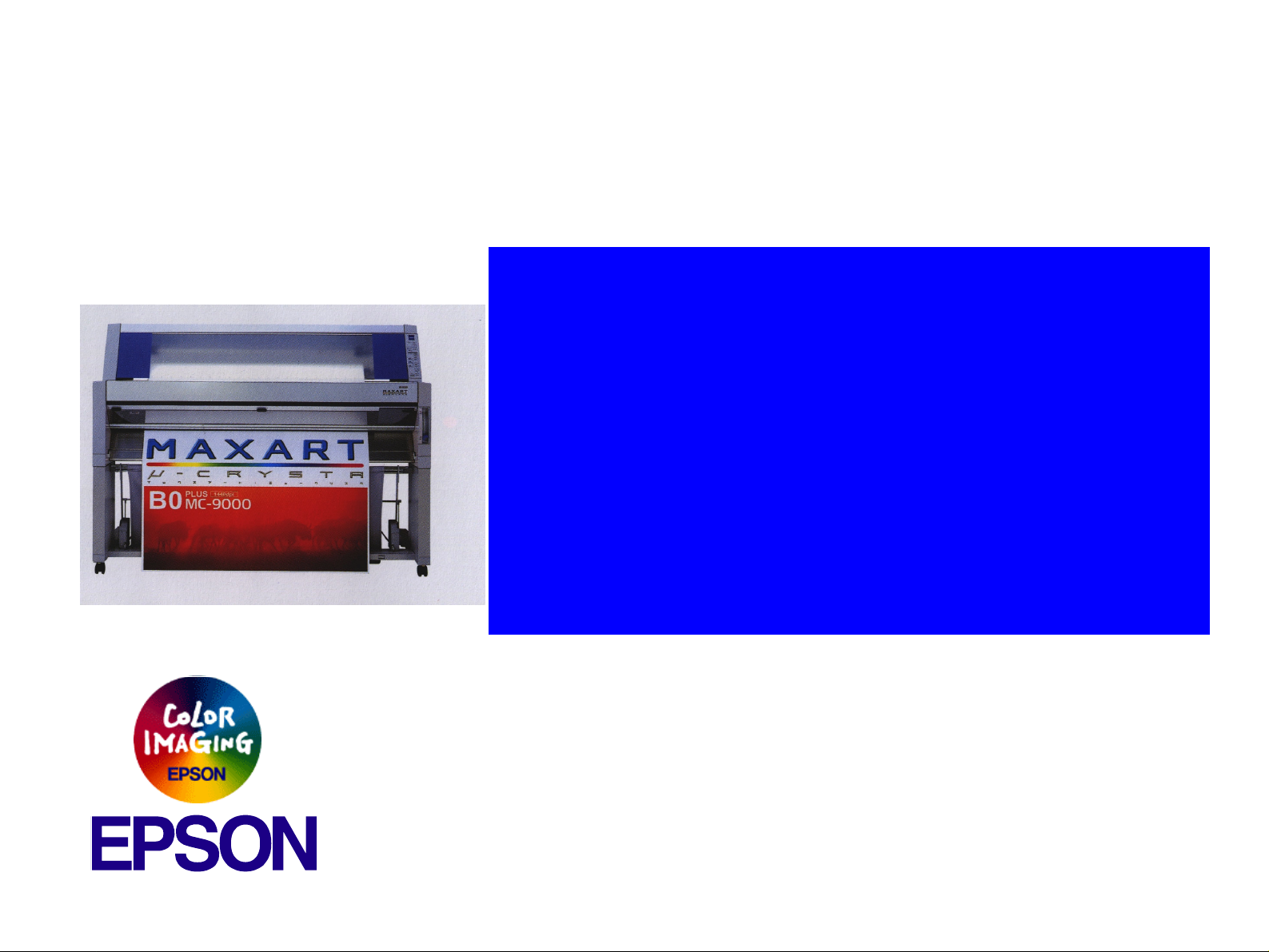
B0 Wide-Format Professional Inkjet Printer
EPSON Stylus Pro 9500
SEIJ00005
Page 2

EPSON Stylus Pro 9500 Revision A
NOTE:
The contents of this book may change at anytime without notice.
No patent liability is assumed with respect to the use of information contained herein.
SEIKO EPSON CORPORATION assumes no liability for problems or damages resulting from the use of the information contained
herein.
EPSON is a registered trademark of SEIKO EPSON CORPORATION.
Other product names used herein are for identification purposes only and may be trademarks of their respective owners. EPSON
disclaims any and all rights in those marks.
Copyright 2000 SEIKO EPSON CORPORATION.
2
Page 3
EPSON Stylus Pro 9500 Revision A
PRECAUTIONS
There are cautionary notes throughout the text to help you avoid personal injury or equipment damage.
W ARNING
Signals a precaution which, if ignored, could result
in serious or fatal personal injury. Great caution
should be exercised in performing procedures
preceded by a WARNING heading.
Always observe the measures listed below when performing repair o r maint enance procedures.
CAUTION
Signals a precaution which, if ignored, could result
in damage to equipment.
WARNING
1. Always disconnect the product from both the power source and host computer before performing any maintenance or repair procedure.
2. No work should be performed on the unit by persons unfamiliar wit h basic safety measures dictated for all electronics technicians in their line of
work.
3. In performing testing described in this manual, do not connect the unit to a power source until instructed to do so. When the power supply cable
must be connected, use extreme caution in working on the power supply and other electronic components.
CAUTION
1. Repairs on EPSON products should be performed only by an EPSON-certified repair technician.
2. Make certain that the sourc e voltage is t he same as the rated voltage li sted on the seri al number/rat ing plate. If the EPSON product has a primar y
AC rating different from the available power source, do not connect it to the power source.
3. Always verify that the EPSON product has been disconnected from the power source before removing or replacing printed circui t boards and/or
individual chips.
4. To protect sensitive microprocessors and circuitry, use static discharge equipment, such as anti-static wrist straps , when accessing internal
components.
5. Replace malfunctioning components only with those components recommended by the manufacturer; i ntroduction of second-source ICs or o ther
nonapproved components may damage the product and void any applicab le EPSON warranty.
3
Page 4
EPSON Stylus Pro 9500 Revision A
Revision Status
Revision Issued Date Description
A 31 August 2000 First Established Edition
4
Page 5

PRODUCT DESCRIPTION
ADJUSTMENT
Features ................................... ....... ...... ....... ...... ....... ...... ....... ...... .................. 7
Professional Color Printing Features......................................................... 7
Consumable Products & Options.............................................................. 8
SPECIFICATIONS. ....... ...... ...... ....... ...... ....... ............................................. ..... 9
Interfaces................................................................................................. 18
Initialization.............................................................................................. 23
Control Panel................................................................................................ 24
Normal Mode Panel Display.................................................................... 27
Control Panel Settings............................................................................. 28
Maintenance Call..................................................................................... 34
Service Errors....................................................... ...... ....... ...... ....... ......... 35
Service Related Printer Settings ............................................................. 37
Firmware Update..................................................................................... 41
Jumper Settings ......................... ...... ....... ...... ....... ...... ....... ...... ....... ...... ... 42
OPERATING PRINCIPLES
Component List & Illustrations...................................................................... 44
Print Mechanism Components................................................................ 44
Summary of Control Circuit Operations................................................... 64
TROUBLESHOOTING
Outline.......................................................................................................... 70
Test Points .............................................................................................. 70
General Errors......................................................................................... 75
DISASSEMBLY & ASSEMBLY
Summary ...................................................................................................... 83
Warnings ................................................................................................. 83
Tools........................................................................................................ 84
Screw List................................................................................................ 84
Disassembly Flow......................................................................................... 85
Removing the Housing............................................................................ 86
Circuit Board Removal ............................................................................ 93
Printer Mechanism Disassembly............................................................. 96
Conversion Kit...................................................................................... 122
Summary.................................................................................................... 156
Caution.................................................................................................. 156
Adjustment Tools .................................................................................. 156
Adjustment Items .................................................................................. 158
Adjustment Steps ....................................................................................... 161
Parameter Backup ................................................................................ 161
Firmware Update................................................................................... 164
Self-Diagnostics .................................................................................... 166
Adjustment Menu .................................................................................. 168
Test Menu ............................................................................................. 189
Cleaning menu...................................................................................... 198
Parameter menu ................................................................................... 198
Maintenance Mode................................................................................ 200
Mechanism Adjustment......................................................................... 203
Dip SW setting ...................................................................................... 218
MAINTENANCE & SETUP
General Maintenance Issues...................................................................... 220
Periodic Maintenance Items.................................................................. 221
Product Life Information ........................................................................ 222
Important Maintenance Items During Service Operations .................... 222
Lubrication............................................................................................. 223
Unpacking and Installing ...... ...... ...... ....... ...... ....... ...... ....... ...... ....... ...... ...... 223
The Packaging ......... ....... ...... ...... ....... ...... ....... ...... ....... ...... ....... ............ 223
Contents of the Packaging.................................................................... 224
Unpacking and Assembling...................... ....... ...................................... 225
APPENDIX
Wiring Diagrams......................................................................................... 233
Connector Pin Assignments ....................................................................... 235
C277MAIN Board.................................................................................. 235
Parts List .................................................................................................... 239
Exploded view Diagram.............................................................................. 248
Component Layout.................................. ...... ....... ...... ....... ...... ....... ...... ...... 262
Circuit Diagrams......................................................................................... 264
Page 6

PRODUCT DESCRIPTION
CHAPTER
Page 7

EPSON Stylus Pro 9500 Revision A
1.1 Features
The EPSON Stylus Pro 9500 is an ultra-wide, 6-color ink jet printer with
professional color output. It has the same printheads as the EPSON Stylus
Color 9000. The EPSON Stylus Pro 9500 provides the following major features
and more.
1.1.1 Professional Color Printing Features
o Large-size/poster printing
up to B0-wide paper (1118 cm/44 inches) including print-registration marks
o Excellent Photo-quality printing
1440 (H) x 720 (V) dpi combined with EPSON’s Microdot printing
o High-speed printing
n 64 nozzles per color (same printhead as the EPSON Stylus Pro 9000)
n The RISC-CPU and high-speed color raster ASIC quickly process
detailed print data
n A0/Medium Gloss Paper: Approx.17 min.(720x720dpi /Fast)
A0/Medium Gloss Paper: Approx.25 min.(720x720dpi /Beautiful)
A0/Medium Gloss Paper: Approx.50 min.(1440x720dpi /Highly detailed)
o Low running cost
Six separate ink cartridges so you only have to replace the empty ink
cartridge (each cartridge holds 220 ml)
o User-friendly features:
n Two roll holders for easy switching between paper types
n Standard roll-paper cutter
n Auto Loading (Cut sheet)
n Optional roll-paper take-up reel for automatically winding up your long
printouts
o Wide compatibility
The following interface alternatives are available:
n IEEE-1284 bidirectional parallel interface (supports ECP mode)
n Macintosh serial interface (approx. 1.8Mbps)
n One Type-B expansion slot for an optional interface (x1)
Product Description Features 7
Page 8
EPSON Stylus Pro 9500 Revision A
1.1.2 Consumable Products & Options
The following table lists the consumable items and options available for use
with the EPSON Stylus Pro 9500.
Table 1-1. Consumable Products & Available Options
Name Code Product
Doubleweight Matte
Paper
Glossy Paper - Photo
Weight
Premium Glossy Photo
Paper
Premium Semigloss
Photo Paper
Watercolor Paper Radiant White
Glossy Film
Synthetic Paper
Adhesive Syn thetic
Paper
S041385
S041386
S041387
S041388
S041389
S041390
S041391
S041392
S041393
S041394
S041395
S041396
S041397
S041398
S041352
S041351
S041314
S041313
S041312
S041399
S041400
S041401
S041402
S041403
S041404
24in. wide / 25m long
36in. wide / 25m long
44in. wide / 25m long
22in. wide / 20m long
44in. wide / 20m long
24in. wide / 30.5m long
36in. wide / 30.5m long
44in. wide / 30.5m long
24in. wide / 30.5m long
36in. wide / 30.5m long
44in. wide / 30.5m long
24in. wide / 18m long
36in. wide / 18m long
44in. wide / 18m long
A3 Wide / B
A3 Wide / B
610mm wide / 20m long
914mm wide / 20m long
1118mm wide / 20m long
24in. wide / 45m long
36in. wide / 45m long
44in. wide / 45m long
24in. wide / 30m long
36in. wide / 30m long
44in. wide / 30m long
Table 1-1. Consumable Products & Available Options (continued)
Name Code Product
Rip Station 5100 PS
Server Series
Multi-protocol Ethernet
interface card
100Mbps Multi-protocol
Ethernet interface card
Note *: Two rolls can be installed at the same time.
Note **: Can only be installed in the upper spindle holder.
Note 3: These papers can be used in the Stylus Pro 9000 also.
EAI - C850092
Other - C850093
C82362¬ Type-B 10Base-T
C82363¬ Type-B 100Base-T
Fiery Adobe® PostScript® 3™
Server
Product Description Features 8
Page 9
EPSON Stylus Pro 9500 Revision A
1.2 SPECIFICATIONS
PRINT SPECIFICATIONS
Print method: On-demand MACH (Multi-layer Actuator Head) ink
jet E-MACH type
Nozzle configuration: Black: 64 nozzles
Color: 320 nozzles/64 nozzles for each color (Yellow,
Magenta, Cyan, Light Magenta, and Light Cyan)
Print direction: Bi-directional with logic seeking
(high-speed return and skip only)
Print speed: See the following table:
n <Character mode>
Character Quality: High quality
Character Pitch: 10 cpi
Printable Area: 437 colu mns
Print Speed: 240 cps
n <Graphic mode>
See the table below.
n Character Code
PC 850 (Multilingual)
PC437 (US, Standard Europe)
n Type Faces
Bitmap LQ font: EPSON Courier IO CPI
PAPER-FEED SPECIFICATIONS
Feeding method: Friction feed
Line spacing: 1/6 or 1/720” programmable
Paper loading: Roll paper (two 2-inch rolls can be loaded at the
same time)
Single sheets loaded one at a time
Paper volume: 2” core roll paper = diameter of paper wound on roll
of less than 103mm (4.05”)
3” core roll paper = diameter of paper wound on roll
of less than 150mm (5.9”)
Single sheets = one sheet at a time
Feed speed: 200 ± 10 ms (when feeding at 1/6”)
2.5”/second (when continuously feeding)
Table 1-2. Print Speed by Print Mode
Table 1-2.
Horizontal
Resolution
360 1112mm 15762 241 IPS/FOL
720 1112mm 31524 33. 31 IPS/FOL
1440 1112mm 63048 24IPS/FOL
Control code: ESC/P Raster (commands are not open to public)
Character Specifications:
Printable Area
Printable Dot
Count
Print Speed
33.31 IPS/4pass
33.31 IPS/4pass
Product Description SPECIFICATIONS 9
Page 10

EPSON Stylus Pro 9500 Revision A
PAPER SPECIFICATIONS
Size, roll paper {Minimum paper requireme nts}
Paper meeting the requirements described below
can be used with this printer, but neither the feeding
nor printout quality is guaranteed.
•Paper Size = Width 297~1118mm
(8.27~44.02”)
Length 720mm~45m
(28.35~1771.65”)
•Roll Size = 2” or 3” core
paper thickness = 103mm or less (4.05”)
150mm or less (5.9”)
•Paper Thickness = 0.08~0.5mm (0.003~0.019”)
*1): There should be no wrinkles, fuzz, tearing or
folding, of the paper, etc.
* 2): The exclusive option (3” roll paper spindle)
should be used when using 3” core roll paper.
{Normal paper}
For paper meeting the following requirements, the
feeding operation only is guaranteed.
•Paper Size = Width 297~1118mm
(8.27~44.02”)
Length 720mm~45m
(28.35~1771.65”)
•Roll Size = 2” or 3” spindle
paper thickness = 103mm or less (4.05”)
150mm or less (5.9”)
•Paper Thickness = 0.08~0.11mm (0.003~0.0043”)
•Paper Weight = 64~90gf/m
•Paper Quality = Normal paper, recycled paper
*1: Use at normal room temperature
(15~25°C (59~77°F)
2
(two 2” rolls)
(one 3” roll)
(two 2” rolls)
(one 3” roll)
(17~24 lb.s)
40~60% humidity)
*2: The printer exerts between 300~500gf to peel
off the rear edge of roll paper from the core
*3: The exclusive option (3” roll paper spindle) is
necessary when using 3” core roll paper.
*4: This product should be used in a place with a
normal room temperature environment
(Temperature: 15~25°C, Relative humidity:
40~60%)
*5: The guaranteed printable area for roll paper is
from the core to the point where it is cut off.
(Reference: The remaining paper length when the
paper comes off the roll is approximately 400 mm for
the upper holder and approximately 300 mm for the
lower holder.
{Special paper}
For special paper meeting the following
requirements, the feeding operation and print quality
are optimized.
Product Description SPECIFICATIONS 10
Page 11

EPSON Stylus Pro 9500 Revision A
Table 1-3. Special Paper Specifications
Paper Code Paper Size Roll Size
Doubleweight
Matte Paper
Glossy Paper Photo Weight
Premium Glossy
Photo Paper
Premium
Semigloss Photo
Paper
Watercolor Paper
- Radiant White
Glossy Film
Synthetic Paper
Adhesive
Synthetic Paper
S041385
S041386
S041387
S041388
S041389
S041390
S041391
S041392
S041393
S041394
S041395
S041396
S041397
S041398
S041314
S041313
S041312
S041399
S041400
S041401
S041402
S041403
S041404
*1):There should be no wrinkles, fuzz, tearing or
folding, of the paper, etc.
24” x 25m
36” x 25m
44” x 25m
22” x 20m
44” x 20m
24” x 30.5m
36” x 30.5m
44” x 30.5m
24” x 30.5m
36” x 30.5m
44” x 30.5m
24” x 18m
36” x 18m
44” x 18m
610mm x 20m
914mm x 20m
1118mm x
20m
24” x 45m
36” x 45m
44” x 45m
24” x 30m
36” x 30m
44” x 30m
2” core/ paper thickness
(radius) of 103mm or less
(Reference: The remaining paper length when the
paper comes off the roll is
Approximately 400 mm for the upper holder and Approximately 300 mm for the
lower holder.
*2):This product should be used in a place with a
normal room temperature environment
(Temperature: 15~25°C, Relative humidity:
40~60%)
* 3):The guaranteed printable area for roll paper is
from the core to the point where it is cut off.
Product Description SPECIFICATIONS 11
Page 12
EPSON Stylus Pro 9500 Revision A
CUT SHEET PAPER SPECIFICATIONS
Loading of the following papers into this printer is possible, but for papers
other than the following plain paper and exclusive paper, feed through
characteristics and print quality are not guaranteed.
Table 1-4. Usable Single Sheet Paper Specifications
Size
Super B0 1118 x 1580mm A2 329 x 483mm
B0 1030 x 1456mm Super A3/B 297 x 483mm
B1 728 x 1030mm A3 297 x 420mm
B2 515 x 728mm ANSI E 34 x 44”
B3 364 x 515mm ANSI D 22 x 34”
Super A0 914 x 1292mm ANSI C 17 x 22”
A0 841 x 1189mm
A1 594 x 841mm
Dimensions
(W x H)
Size
ANSI B 11 x 17”
Paper Thickness: 420~728mm (16.54~28.66”) long
paper = 0.08~1.5mm
(0.003~0.059”)
728~1580mm (28.66~6 2.2” ) long
paper = 0.08~0.5mm
(0.003~0.019”)
Dimensions
(W x H)
Table 1-5. Usable Single Sheet Paper Specifications
Size
Super B0 1118 x 1580mm A2 329 x 483mm
B0 1030 x 1456mm Super A3 /B 297 x 420mm
B1 728 x 1030mm A3 22 x 36”
B2 515 x 728mm ANSI E 20 x 24”
B3 364 x 515mm ANSI D 18 x 22”
Super A0 914 x 1292mm ANSI C 34 x 44”
A0 841 x 1189mm
A1 594 x 841mm 17 x 22”
A2 420 x 594mm 11 x 17”
[Exclusive Papers]
{Normal paper}
For paper meeting the following requirements, only
the feeding operation is guaranteed.
Dimensions
(W x H)
Size
ANSI B 22 x 34”
Dimensions
(W x H)
• Paper Thickness = 0.08~0.11mm (0.003~0.0043”)
• Paper Weight = 64~90gf/m
2
(17~24 lb.s)
• Paper Quality: Nor m al, re cyc led paper
*1:Load short edge first (portrait)
The following genuine exclusive papers can be used.
Table 1-6. Specifications of Genuine Exclusive Papers
Paper Name Dimensions (H x W) MC Glossy Paper *1 MC Imaging Paper
A3
Super A3
*1: Guaranteed for Uni-D printing. The paper should be loaded longitudinally.
*2: There should be no wrinkles, fuzz, tearing or folding, of the paper, etc.
*3: This product should be used in a place with a normal room temperature environment
(Temperature: 15~25°C, Relative humidity: 40~60%).
297mm x 420mm
329mm x 483mm
¡
¡
-
-
Product Description SPECIFICATIONS 12
Page 13
EPSON Stylus Pro 9500 Revision A
Printable area:See the following illustration and table for details.
Table 1-7. Printable Area
Heading Roll Paper Cut Sheets
PW (width)
PL (length)
LM (left margin)
TM (top) 3mm/15mm* 3mm
RM (right) 3mm/15mm* 3mm
BM (bottom) 3mm/15mm* 14mm
Note 1): The printer detects the paper width when the paper is set. (The paper width is not
detected when the paper width detection setting is Off.)
Note 2): Any image that exceeds the detected paper width, or the printable area specified by the
paper size setting, is not printed. (When paper detection setting is OFF, the printer may
print on the platen.)
Note 3): The size of the margin of roll paper can be changed from the panel as shown below.
Top and Bottom: 15 mm Left and Right: 3 mm, Top, Bottom, Left and Right: 3 mm,
Top, Bottom, Left and Right: 15 mm.
297 ~ 1118mm
(8.27 ~ 44.02”)
720mm ~ 45m
(8.27~1771.65”)
3mm/15mm*
(0.12~0.59”)
297 ~ 1118mm
(8.27 ~ 44.02”)
420~1580mm
(16.54~62.2”)
3mm
LM
Paper
Feed
PW
Printable Area
RM
TM
PL
BM
Figure 1-1. Printable Area
Product Description SPECIFICATIONS 13
Page 14

EPSON Stylus Pro 9500 Revision A
PAPER SET LEVER:
Lever Position = Up
o
The paper support is released and paper setting is possible.
o Lever Position = Down
The paper is in a fixed position and is ready to print on.
During printing, it is impossible to change the position of the paper set
lever.
During printing, an error occurs if the paper set lever is raised.
ELECTRICAL SPECIFICATIONS
Rated voltage range AC100~240V
Input voltage range AC90~264V
Rated frequency range 50 to 60Hz
Input frequency range 49 to 61Hz
Rated current
Power consumption
100 V System = 1.0 A
200 V System = 0.5 A
During operation = 100 W or less
During standby = 30 W or less
CONFORMITY/SAFETY APPROVALS
Safety Standards:
US Model UL 1950, CSA 22.2 No. 950
European Model EN60950 (VDE)
EMC:
US Model FCC part 15 subpart B class B
CSA C108.8 class B
European Model EN 55022 (CISPR Pub. 22) class B
EN 61000-3-2
EN 61000-3-3
EN 50082-1
IEC 801-2
IEC 801-3
IEC 801-4
Australian Model AS/NZS 3548 class B
International Energy Star Compliant
(EPA MOU2.1 Category Large Format Printer)
Insulation resistanc e
Dielectric strength
Current leakage 0.25 mA or less
10MW or higher
(CD 500 V / Between AC lin e and chassis)
AC 1.0 Kvrms / 1 min. or
AC 1.2 Kvrms / 1 sec. (between AC line and chassis)
Product Description SPECIFICATIONS 14
Page 15

EPSON Stylus Pro 9500 Revision A
RELIABILITY
Service Life: [Body] 20,000 Page (A0)
[Print Heads] 2 billion dots/nozzle
[Cutter] Approx. 2,000 times (Super B0)
Replacement Parts Service Life:
After printing of approx. 6200 sheets (A0), the
following parts are subject to simultaneous service
replacement.
• Waste ink pad
• Pump assembly
• Cap assembly (New part)
• Flushing box R
• Flushing box L (New part)
• Cleaner blade
CHECK
PO IN T
The above service replacement parts are available in
the following kit.
n Name: “Maintenance Kit Sylus Pro 9500
n Part Code: 1058462
n This maintenance kit is an exclusive kit for the
Sylus Pro 9500, and should not be used for the
Stylus Pro 9000.
ENVIRONMENTAL SPECIFICATIONS
Temperature/Humidity: See the following table.
Table 1-8. Temperature & Humidity
Condition Temperature Humidity Notes
Operating
Storage
Transportation
Notes:
1) When storing the printer, make sure the printheads are in the home, capped, position.
2) Before transporting the printer, remove the ink cartridges and turn the ink valves screws to
the closed position. Also make sure the printheads are in the home, capped, position. After
transporting the printer, install new ink cartridges.
3) When the temperature drops below -15°C (5
freezes. The ink thaws completely after three hours at 25°C (77
15~35°C
(59~95°F)
-20~40°C
(-4~104°F)
-20~60°C
(-4~140°F)
30~80%
20~85%
5-85%
°F), the ink in the cartridges and printheads
• Less than a month at
40°C (104°F)
Less than 120 hours at
60°C (140°F)
• Without condensation
°F).
Product Description SPECIFICATIONS 15
Page 16
EPSON Stylus Pro 9500 Revision A
Humidity (%)
Figure 1-2. Print Temperature and Humidity
Resistance to
Vibration & Shock: See the following table.
Table 1-9. Vibration & Shock Resistance
Temp.
(°C)
INK CARTRIDGE SPECIFICATIONS
Shape: Each ink cartridge is uniquely shaped so the
cartridges cannot be inserted in the wrong slots.
Ink colors: Black, Cyan, Magenta, Yellow, Light Cyan, Light
Magenta
Ink volume: 220 ± 5 ml
Ink avail. for printing: 190 ± 14ml
Print capacity: A0 = approx. 30 pages at 720dpi and 40% coverage
Dimensions: 25.1 x 260 x 105.3mm (WxDxH)
Weight: Approx. 370~385g (cartridge only)
Effective period: 2 years from production (in the sealed packaging)
plus time used (at room temp.)
Storage temperature: See the table below.
Table 1-10. Ink Cartridge (Environmental) Specifications
Situation Temperature Notes
Transporting
Storage
Installed
-30~60°C
(-22~140°F)
-30~40°C
(-22~104°F)
-20~40°C
(-4~104°F)
• Less than 120 hours at 60°C (140°F)
• Less than month at 40°C (104°F)
Less than a month at 40°C (104°F)
Less than a month at 40°C (104°F)
Condition
Operating 0.15G
Storage 0.50G
Vibration
Resistance
10~55Hz
10~55Hz
Shock
Resistance
1G
less than 1ms
2G
less than 2ms
Notes
X/Y/Z dir ection
Product Description SPECIFICATIONS 16
Page 17
EPSON Stylus Pro 9500 Revision A
CONTROLLER SPECIFICATIONS
CPU: 32 bit RISC-CPU (SH7043) 33Mhz
ROM: [Program]
CPU Internal = 128KB ROM
External = 1MB (Flash ROM/4Mbit x 2)
[Font] not-installed
RAM: 18MB (fixed)
(16MB: SIMM/2MB: IC18,19)
CHECK
PO IN T
Interface: [Standard]
The RAM installed in the form of a SIMM module is a
part of system memory and cannot be replaced (to
install a larger capacity SIMM) or removed.
IEEE1284 Bidirectional Parallel Interface
Macintosh Serial Interface
Type-B Card Slot (x1) for optional interface
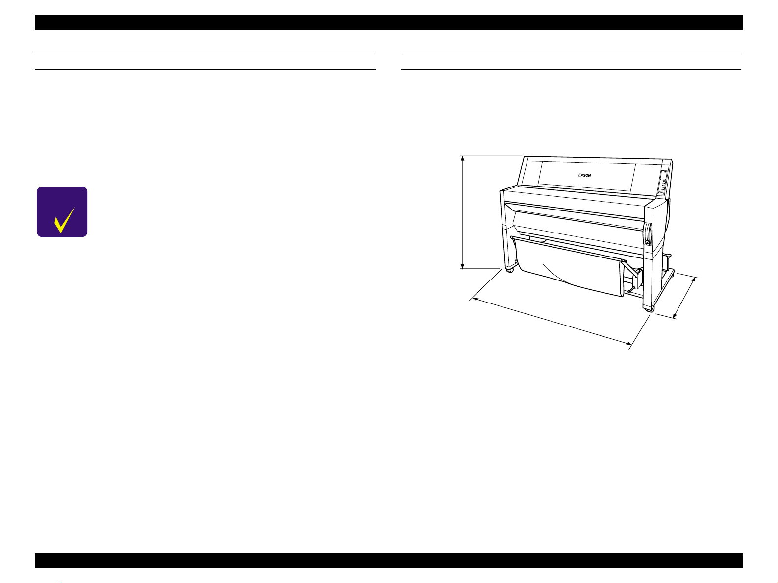
PRINTER DIMENSIONS & WEIGHT
Dimensions: 1688 x 699 x 1259mm (WxDxH)
(66.46 x 27.52 x 49.57 inches)
Weight: 96Kg (211.91 lb.s)
Printer alone = 74Kg (163.32 lb.s)
Stand = 22Kg (48.59 lb.s)
1259mm
(49.57”)
699mm
(27.52”)
1688mm
(66.46”)
Figure 1-3. Printer Dimensions
Product Description SPECIFICATIONS 17
Page 18
EPSON Stylus Pro 9500 Revision A
1.2.1 Interfaces
The EPSON Stylus Pro 9500 is equipped with parallel and Macintosh serial
interfaces and a card slot for an optional Type-B interface. This section
provides information on each interface.
PARALLEL INTERFACE
Parallel Interface [Compatibility Mode]
o
Transmission mode: 8-bit parallel, IEEE-1284 compatibility mode
Synchronization: By STROBE pulse
Handshaking: By BUSY and ACKNLG
Logic Level: TTL compatible level (IEEE-1284 Level 1 device)
Connector: 57-30360 (Amphenol) or equivalent 36-pin. The
interface cable length should be only long enough to
reach the shortest necessary distance.
signal
Table 1-11. Connector Pin Assignments - Forward Channel
Pin
No.
2-9
10
11
12
13
14
15
16
17
18
19-30
31
32
33
34
35
36
Note:See the next page.
Signal
Name
STROBE
1
DATA0~7
ACKNLG
BUSY
PE
SLCT
AFXT
NC Not connected
GND Ground for twisted pair return
Chassis Ground for frame/body
Logic H Pulled up to +5V via 3.9Kohm
GND Ground for twisted pair return
-INIT
ERROR
GND
NC
+5V
SLCTIN
Return
Pin
19 I
20-27 I
28 O
29 O
28 O
28 O
30 I
30 I
29 O
---- ----
---- ----
---- O
30 I
In/
Out
Data reception pulse, 0.5uS or greater pulse width
required. Usual state is HIGH, and reads data after
going to LOW state.
The DATA0 through DATA7 signals represent data bits
0 to7, respectively. Each signal is at high level when
data is logical 1 and low level when data is logical 0.
These signals are used to transfer the 1284 extensibility
request values to the printer.
When LOW the printer has finished preparing to receive
signals and can accept data. Pulse width is about 1uS or
3uS Printer clock signal.
HIGH means the printer cannot receive data. This
occurs when the printer is receiving data or when the
printer is in an error state.
HIGH means no paper is loaded. (LOW means an error.)
Always HIGH. Pulled up to +5V via 1.0Kohm
Not used
Pulse width of 50uS or more means LOW pulse, and the
falling edge of LOW signal causes the printer to initialize.
LOW means printer error
Ground for twisted pair return
Not connected
HIGH during normal operation. Pulled up to +5V via
1.0Kohm
Not used
Functional Description
Product Description SPECIFICATIONS 18
Page 19
EPSON Stylus Pro 9500 Revision A
Note 1: *1 The return side means the twisted pair return and is connected to the signal ground
level. Furthermore, when interfacing, a twisted pair cable should definitely be used for each
signal and the return side should definitely connected. Also, use of a shielded cable and
connection to the chassis ground of the center machine and the printer, respectively are
effective countermeasures against noise.
Note 2:All the interface conditions are TTL level standard conditions. The rise and fall time of each
signal is 0.2 _s or less.
Note 3:There must not be any data transfer with disregard of the /ACKNLG or BUSY signals. (Data
transfer to this printer must be performed after the ACKNLG level is confirmed or when
BUSY is in the “LOW” state.)
Note 4: A horizontal line above the signal name sows a LOW active signal.
Table 1-12. Parallel Interface Timing
Parameter Minimum Maximum
tsetup 500ns --
thold 500ns --
tstb 500ns --
tready 0 --
tbusy -- 500ns
treply --
tack Typical 2us
Tnbusy 0 --
tnext 0 --
o Nibble Mode
Transmission mode: 8-bit Parallel
Synchronization: External Supply STROBE Pulse Signal
Handshaking: ACKNLG and BUSY Signal
Signal level: TTL level (IEEE-1284 level 1 device)
Connector: 57-30360 (Amphenol) or equivalent
Data transfer timing: Refer to IEEE-1284 specification
Data requests
: When the printer receives the hexadecimal values 00H
or 04H, the printer responds in the following manner:
00H: The printer enters reverse channel mode, allowing
data to be sent to the host.
04H: The printer sends the device ID to the host; the
device ID consists of the following strings
device ID:
<00H><4EH>
MFG: EPSON
CMD: ESCPL2, BDC
MDL: Stylus[SP]Pro[SP]9000;
CLS: PRINTER
DES: EPSON[SP]Stylus[SP]Pro[SP]9500
Note: [SP] equals space code 20H
Table 1-13. Connector Pin Assignments - Reverse Channel
Pin
No.
19-30 GND Ground for twisted pair return
Signal Name
1 HostClk 19 I
2-9 Data0-7 20-27 I
10 PeriphClk 28 O Printer side clock signal.
PeriphAck/
11
PtrBusy
12 AckData Req 28 O
13 Xflag 28 O
14 HostBusy 30 I Hos t com pute r side BUS Y signal.
15 NC (Not used.)
16 GND Ground for twisted pair return.
17 Chassis GND Chassis Ground
18 Logic-H O +5 V pull-up at 3.9 K Ohm.
31 /INIT 30 I (Not used.)
32 /DataAvail 29 O
33 GND Ground for twisted pair return
Return
Pin
29 O
In/
Out
Functional Description
Host clock signal.
Each signal is at high level when data is
logical 1 and low l ev el w h en data is logical 0.
Printer side BUSY signal and data bit 3/7
in the reverse channel.
Acknowledge data request si gna l and
data bit 2/6 in the reverse channel.
X-flag signal and data bit 1/5 in the
reverse channel.
Data Available signal and data bit 0/4 in
the reverse channel.
Product Description SPECIFICATIONS 19
Page 20
EPSON Stylus Pro 9500 Revision A
Table 1-13. Connector Pin Assignments - Reverse Channel
Pin
Signal Name
No.
34 NC (Note used.)
35 +5V ---- O
36 1284-Active 30 I 1284 Active signal.
o
ECP Mode
Transmission mode: IEEE-1284 ECP mode
Synchronization: Refer to IEEE-1284 specification
Handshaking: Refer to IEEE-1284 specification
Signal level: TTL level IEEE-1284 level 1 device
Data transfer timing: Refer to IEEE-1284 specification
Data requests: When the printer receives the hexadecimal values 10H or
device ID: <00H><4EH>
Return
Pin
In/
Out
Functional Description
Normally HIGH state. +5 V pull-up at 1.0
K Ohm
14H, the printer responds in the following manner:
10H: The printer enters reverse channel mode, allowing
data to be sent to the host.
14H: The printer sends the device ID to the host; the
device ID consists of the following strings:
MFG: EPSON
CMD: ESCPL2, BDC
MDL: Stylus[SP]Pro[SP]9500
CLS: PRINTER
DES: EPSON[SP]Stylus[SP]Pro[SP]9500
Note: [SP] equals space code 20H
Table 1-14. Connector Pin Assignments - Reverse Channel
Pin
No.
Signal Name
1 HostClk 19 I
2-9 Data0-7 20-27 I
10 PeriphClk 28 O
PeriphAck/
11
PtrBusy
12 AckData Req 28 O
13 Xflag 28 O
14 HostBusy 30 I
15 NC - - (Not used.)
Return
Pin
29 O
In/
Out
Functional Description
Host clock signal.
Each signal is at high level when data is
logical 1 and low l ev el w h en data is logical 0.
Transmits data to the host computer
from the printer.
The printer uses this signal for forward
direction flow control. Also, this signal
offers data bit 9, which is used to judge
whether information output in the
reverse direction data signals is
command information or data
information.
The printer drives in Low and
acknowledges a nReverseRequest.
X-flag signal and data bit 1/5 in the
reverse channel.
The host uses this signal for reverse
direction flow control. Also, this signal
offers data bit 9, which is used to judge
whether information output in the
forward direction data signals is
command information or data
information.
16 GND - - Ground for twisted pair return.
17 Chassis GND Chassis Ground
18 Logic-H - O
19-30 GND - - Ground for twisted pair return.
31 /INIT 30 I (Not used.)
32 /DataAvail 29 O
Normally “HIGH” level. +5 V pull-up at
3.9 K Ohm
This signal is used to generate host
interrupts.
Product Description SPECIFICATIONS 20
Page 21
EPSON Stylus Pro 9500 Revision A
Table 1-14. Connector Pin Assignments - Reverse Channel
Pin
Signal Name
No.
33 GND Ground for twisted pair return.
34 NC (Not used.)
35 +5V ---- O
36 1284-Active 30 I
Return
Pin
In/
Out
Functional Description
Normally HIGH state. +5 V pull-up at 1.0
K Ohm.
1284 Active signal. “HIGH” when in the
ECP mode.
SERIAL INTERFACE
Transmission mode: Based on RS-423
Synchronization: Synchronous
Transfer speed: About 1.8 Mbps
Data format: Start bit: 1 bit
Data bit: 8 bits
Parity bit: None
Stop bit: 1 bit
Handshaking: X-ON/X-OFF, DTR protocol
Adaptable connector: 8-pin mini-DIN
Recommended I/F cable: Apple Genuine Cable
Product Description SPECIFICATIONS 21
Page 22
EPSON Stylus Pro 9500 Revision A
Table 1-15. Pin Assignment
Pin No.
1 SCLK O Synchronous clock signal
2 CTS I Clear To Send
3 TXD- O Transmit Data (-)
4 SG I (Signal Ground)
5 RXD- I Receive Data (-)
6 TXD+ O Balanced Transmit Data (+)
7 DTR O Data Terminal Ready
8 RXD+ I Balanced Receive Data (+)
o
DTR, Xon, Xoff Handshake Timing:
Signal
Name
I/O Description
Table 1-16. DTR, XON/XOFF Handshake Timingl
State Buffer Space X-ON/X-OFF DTR
Busy Less than 3072 bytes Send X-OFF code OFF
Ready More than 5120 bytes Send X-ON code ON
OPTIONAL INTERFACE
A Type B optional interface (Level 2 / 1200 mA type) can be used.
o Reply Message:
<When a Coax or Twinax Interface is installed> (Short Version)
n When using Co-ax/Twin-ax interface card:
Main type: MTP48p, PW12 7c l1 0c pi, PRG (KAx xx x)r ev,
AP1200ma
Product name: Stylus[SP]Pro[SP]9500
Emulation type: ESCPL2-00
Entity type: EPSONLQ2
<When an interface other than the above is installed>
Main type: M TP 48p , PW12 7c l1 0c pi, PRG (KAx xx )r ev,
AP1200ma, SPD0fast
Product name: Stylus[SP]Pro[SP]9500
Emulation type: ESCPL2-00
Entity type: ESPONLQ2
1.2.1.1 Receiving Buffer Full Operation
When receiving data via the parallel interface or the optional Type B interface
while in a state where no error has occurred (including the Pause state), if the
available capacity of the buffer drops to 4 KB or less, the printer receives at 1
byte/sec. and prevents the host from issuing a time out.
At the point when the available capacity of the buffer becomes 8 KB or higher,
1 byte/sec. reception is canceled and reception stops when the available
capacity is 32 bytes or less. At the point when the available capacity recovers
to 1K-byte or higher, reception at 1 byte/sec. is resumed.
Product Description SPECIFICATIONS 22
Page 23

EPSON Stylus Pro 9500 Revision A
1.2.1.2 Interface Selection
It is possible to switch between the manual fixed selection function or auto
selection function to select one of the interfaces which the printer is equipped
with (parallel, serial or optional interface).
o Manual Fixed Selection:
One of the interfaces which the printer is equipped with, can be selected
and fixed as the default setting.
o Auto Selection Function:
After the power is turned on, the interface from which data are first
received is selected. After that, if a predetermined period of time (fixed at
10 seconds) passes during which the reception of data is stopped, the
printer enters the idle state (a state where no interface is selected), then
selects the interface from which it first receives data next.
o Concerning interface selection and interface state:
n When an interface other than the parallel interface is selected, the
parallel interface is set in the BUSY state. At this time, the LH signal
goes “L.” The meaning of LH = L is that the power is cut off. That is, it
shows that the 1284 interface cannot respond. Therefore, a host
computer requesting reverse transmission must first check LH.
When the serial interface is not selected, DTR switches to the MARK
(High) state.
n When the optional interface is not selected, the OFF-LINE bit is set in
the Main Status Register (MNSTS).
n After the printer has been initialized, or when it is in the idle state (with
no interface selected), the status of each interface is a shown below.
• Parallel Interface : READY State
• Serial Interface : DTR = SPACE (Low) State
1.2.2 Initializat io n
This section describes the initialization procedures for the EPSON Stylus Pro
9500. There are three ways to initialize the EPSON Stylus Pro 9500:
o Hardware initialization:
When the power is turned on or a cold-reset command is sent to the printer
(remote RS command), the printer does the following:
n Initializes the printer mechanism
n Clears the input data buffer
n Clears the print buffer
n Restores the default values
o Software initialization:
When the printer receives an ESC@ command, it does the following:
n Clears the print buffer
n Restores the default values
o Control panel (operator) initialization:
When the Reset button is pressed or the printer receives an -INIT signal
(negative pulse) from the parallel inter face, the pr int er :
n Paper Eject (In the case of roll paper, the printed part is skipped and
when “Auto; Cut” is set in the paper select settings of the panel
settings, the paper is cut, and when “Cutter Off” is set, the paper is not
cut.)
n Caps the printheads
n Clears the input data buffer
n Clears the print buffer
n Resets the default values
• Optional Interface : OFF-LINE bit of the Main Status Register
(MNSTS) is reset.
n An interrupt signal, like the -INIT signal of the parallel interface, is
disregarded while that interface is not selected and while in the Nibble
mode or ECP m ode.
Product Description SPECIFICATIONS 23
Page 24
EPSON Stylus Pro 9500 Revision A
1.2.2.1 Initial Settings
The default values are shown below.
Page Position: Current paper position as page-start position
Line feed: 1/6”
Right margin: 440th character
Left margin: 1st character
Character pitch: 10 CPI
Print mode: Text mode (non-raster graphics mode)
Furthermore, as for the panel settings, default settings and remote command
storable items, their contents in memory are set at the default values.
1.3 Control Panel
This section describes the control panel, the buttons, the lights, and the way
you make settings.]
Ink Out
Paper Source
Pause
Reset
3 sec.
SelecType
Item
+
Operate
KC LCMLMY
Paper Out
Roll
Auto Cut
Roll
Cutter Off
Paper Feed
Sheet
Power
_
Cut /Eject
Enter
Cleaning
3 sec.
Figure 1-4. Control Panel
Product Description Control Panel 24
Page 25
EPSON Stylus Pro 9500 Revision A
OPERATION BUTTONS
The functions of each of the buttons on the operation panel are as shown in the
following table.
Table 1-17. Control Panel Buttons & Functions
Button
(Second function)
Power Power on/off N/A N/A
Pause
(Reset)
SelecType
Cut/Eject
(Enter)
Paper Feed ↑ Feeds paper backward *2
Paper Feed ↓
(-)
Paper Source
(Item)
Cleaning
Paper Source
Cut/Eject
Paper Feed ↓
Paper Source
Cut/Eject
Cleaning
Paper Feed ↓
Cut / Eject
Cleaning
Function
(Normal)
• Switch - online/off-line
• Reset (press for three
seconds
Enters SelecType mode
(when printer is in Standby
mode)
Selects *1
•Auto Cut
•Cutter Off
•Sheet
Feeds paper forward *3
Selects paper source
Cleans both heads if
pressed for three seconds
SelecType
Function
N/A
Selects men u or major
category
Confirm and save value
Cycles backward/
increases value
Cycles forward/
decrease value
Selects item or minor
category
N/A
N/A
N/A
N/A
Power-On
Function
Maintenance
mode
N/A
Maintenance
Mode 2
Firmware
Update Mode
Self-
diagnostic
Mode
Notes:
1: During the ink drying time, ink drying is interrupted and the specified operation is
performed.
2: For 2 seconds after the button is pressed, the paper is fed at 12.7 mm/sec. (5.0 cps). If
the button is pressed for 2 seconds longer, the paper is fed at 76.2 mm/sec. (50.0 cps).
However, the paper can be reversed up to a maximum of 200 mm when the button is
pressed once.
3: For 2 seconds after the button is pressed, the paper is fed at 12.7 mm/sec. (5.0 cps). If
the button is pressed for 2 seconds longer, the paper is fed at 76.2 mm/sec. (50.0 cps).
LED INDICATORS
Table 1-18. LED Indicators
LED Status Condition
Operate
(Green)
Paper Out
(Red)
Pause
(Green)
Ink Out K
(Red)
Ink Out C
(Red)
Ink Out M
(Red)
Ink Out Y
(Red)
Ink Out LC
(Red)
•On
•Flashing
•On
•Flashing
•On
•Flashing
•On
•Flashing
•On
•Flashing
•On
•Flashing
•On
•Flashing
•On
•Flashing
• Power on
• Fatal error during data processing or during
power off p rocessing.
• Shows the no paper, roll paper end, roll paper/
cut sheet paper setting difference, paper support
lever released or cle aning impos sible error s tate.
• Shows a paper jam, paper cutting error, paper
skew error, paper recognition error, cut sheet
paper eject failure, or fatal error state.
• Print ready state.
• Blinks during head cleaning, during ink drying
time, and during initial filling processing.
• Ink end error state (K), I/C wrong insertion.
• Ink low state (K)
• Ink end error state (C), I/C wrong insertion.
• Ink low state (C)
• Ink end error state (M), I/C wrong insertion.
• Ink low state (M)
• Ink end error state (Y), I/C wrong insertion.
• Ink low state (Y)
• Ink end error state (LC), I/C wrong insertion.
• Ink low state (LC)
Product Description Control Panel 25
Page 26

EPSON Stylus Pro 9500 Revision A
Table 1-18. LED Indicators
LED Status Condition
Ink Out LM
(Red)
Paper Source
(Auto Cut)
Paper Type
(Cut Off)
Paper Type
(Single Sheet)
•On
•Flashing
•On
•Flashing
•On
•Flashing
•On
•Flashing
• Ink end error state (LM), I/C wr ong insertion.
• Ink low state (LM)
• Roll paper auto cutting is sele cte d (The paper is
cut automatically each page.)
• Difference from the roll paper auto cutting
setting. It shows that cut sheet paper is set.
• Roll paper with the cutter off is selected.
• Difference between the roll paper and cut sheet
paper setting. It shows that cut sheet paper is
set.
• Shows that cut sheet paper is selected.
• Difference between the roll paper and cut sheet
paper setting. It shows that roll paper is set.
Product Description Control Panel 26
Page 27
EPSON Stylus Pro 9500 Revision A
1.3.1 Normal Mode Panel Display
Messages are displayed in the LCD in the operation panel corresponding to the
printer status and error occurrence and other conditions. The messages
displayed are shown in the following table. Furthermore, the messages in the
following table are listed in the order of their display processing priority, from
high priority to low.
Table 1-19. LCD Messages
Display Message Meaning
SERVICE REQ nnnnnnnn *2
MAAINTENANCE REQ nnnn *3
WAIT *1
POWER OFF
INK OUT
COVER OPEN
OPTION I/F ERROR
LOWER PAPER SET LVR
LOAD xxx PAPER
PAPER JAM
PAPER NOT CUT
PAPER NOT STRAIGHT
PAPER OUT
RELOAD PAPER
INK COMPART.OPEN
INK OUT
PRESS PAUSE BUTTON
Fatal error
Printer requires maintenance from qualified service
person (such as replace waste ink tank)
Resetting Timer IC
Clearing NVRAM
Performing reset operation
Performing ink sequence operation
Initializing the printer
Dealing with initial paper operation
Preparing to shut down.
Replacing ink cartridge.
The cover is open.
A Type-B interface error has occurred.
Paper Release lever is in the release position.
Wrong paper loaded.
Paper is caught inside the printer.
Printer did not cut the paper (when Auto Cut selected)
Paper was fed at an angle, and the printer stopped to
prevent printing the page offcentered.
End of roll or sheet (or the paper detect sensor may
have dust or grime blocking its operation)
Paper check error
Replacing ink cartridge
An ink cartridge is empty
Waiting for paper initialize start trigger
Table 1-19. LCD Messages (continued)
Display Message Meaning
PAUSE
INK DRY xx MIN
INK LOW
PRINTING *1
READ *1
RESET
TURN PWR OFF AND ON
Notes:
1: If “Widen” is selected in the “Platen Gap” item in the panel settings, the letter “H” is
displayed in the 20th column.
2: See the separate table, Table 1-30, on page 38.
3: See the separate table, Table 1-29, on page 38.
Pause state.
Printer waits xx minutes before the next print job to
allow ink on previous print job time to dry.
Prepare a replacement cartridge for the color ink
indicated.
Processing print data.
Can receive and print data.
In the process of re-initializing.
Turn the printer off and turn it on again.
Product Description Control Panel 27
Page 28
EPSON Stylus Pro 9500 Revision A
1.3.2 Control Panel Settings
PANEL SETTING MENU SELECTION
By pressing the “SelecType” button while the printer is not printing, the printer
switches to the panel setting mode and the printing state is automatically
disabled. The following menu items are listed in the Panel Setting Mode, and
the setting menu is switched in order and displayed in the LCD each time the
“SelecType” button is pressed once. When selecting a menu, press the “Paper
Source” button once.
To return to the print ready state, press the “SelecType” button until the “Print
Ready” message is displayed in the LCD panel, or press the “Pause” button.
o Menu Selection: “SelecType” Button
o Selecting a Menu Item: “Paper Source” Button
o Mode End: “Pause” Button.
Table 1-20. Control Panel Settings
Menu Item Panel Display
SelecType Menu PRINTER SETTING MENU
Test Print Menu TEST PRINT MENU
Printer Status Menu PRINTER STATUS MENU
Paper Settings Menu PAPER CONFIG.MENU
Cutter Replacement Menu CUTTER REPLACE MENU
Head Alignment Menu HEAD ALIGNMENT MENU
Selecting a menu provides you with detailed options.
Product Description Control Panel 28
Page 29
EPSON Stylus Pro 9500 Revision A
PRINTER SETTING MENU
Table 1-21. SelecType Menu
Display Message Item Notes
Adjusts the P G width. (Normally used in
PLATEN GAP
PAGE LINE
AUTO
WIDE
ON
OFF
AUTO
INTERFACE
PARALLEL
MAC
OPTION
PARA I/F
CODE PAGE
COMFAT
ECP
PC437
PC850
T/B 15mm
ROLL MARG
15mm
3mm
INIT.PANEL EXEC. Initialize control panel setup values
Auto.)
For details concerning the PG setting
value, see the Operation Theory section.
When Auto Cut Off is selected on the
control panel, this setting determines
whether a line for manual cutting is
printed.
Determines which interface the printer
checks for data. Auto con tin uousl y chec ks
all interfaces and is good for normal use.
Determines the data transfer rate when
using this interface.(No rma lly, leave set to
Compatibility.)
Character code setting. (PC437:
expanded graphics/PC850: multi-lingual)
Sets the margin for roll paper. (disa bled for
cut sheet paper)
Vertical 15 mm: A margin of 15 mm is
provided on the left and ri ght o f the printed
portion, and a margin of 3 mm is provided
at the top and bottom / 3 mm: A margin of
3 mm is provided at the top, bottom, left
and right. / 15 mm: A margin of 15 mm is
provided at the top, bottom, left and right.
Notes:
1) The setting values in the above table with underlines are default setting values.
2) In the “Roll Paper Margins” setting, if “Vertical 15 mm” (15 mm is set at the top and bottom, and
3 mm is set at the left and right), or “15 mm” (15 mm is set at the top, bottom, left and right), the
printing position of vertical lines and horizontal lines in the portion where 15 mm is set at a
position 12 mm wider than the logical paper (the minimum margin is an area of 3 mm from the
paper edge). (Therefore, the margin becomes 3 mm + 12 mm = 15 mm.) Also, if the printable
area becomes X = 15 mm or greater from the right edge of the paper, that portion is not printed
on.
3) If the “Paper Skew Error Sensing” setting is turned OFF, even if the paper is skewed as it is
being fed, printing will continue, and even if the printed image spills over the edge of the paper
due to skewing, the printer will not give notice of the error, so the user should take full
responsibility for the possible consequences of this setting.
4) If the “Paper Width Sensor” setting is turned OFF, even if the paper is sensed to be in an
abnormal state, printing can be continued, but in that case, the paper width is decided and
printing continued based on the following standards.
• The paper’s left edge position is made the guide mark position on the paper guide.
• The printable area is the printable area specified in the command.
If the “Paper Width Sensor” setting is turned OFF, if printing is being done on a paper which has
a particularly low reflection rate and cannot be detected by the photosensor, this setting is used.
Through the “Paper Width Sensor” OFF setting, if an image which is larger than the set paper is
printed, printing may be done on the platen, so the user must take the responsibility for the
possible consequences. However, if detection of the top edge of the paper fails, it results in an
error.
PAPER ALIGN
CHK
( Note 3)
PAPER WIDTH
DETECTION
ON
OFF
ON
OFF
Turns the paper feed skew detection
setting ON / OFF. For details, see the
Operation Theory section.
Turns the paper feed paper width
detection ON / Off. For details, see the
Operation Theory section.
Product Description Control Panel 29
Page 30
EPSON Stylus Pro 9500 Revision A
TEST PRINT MENU
Test Print Menu
In the test print menu, the test printing shown in the following table can be
done. Each test is set by operating the following panel buttons. When each test
printing operation is completed, the printer returns automatically to the print
ready state.
o Test print menu selection: See the panel setting menu procedure.
o Test Print item selection: “Paper Source” Button
o Set print execution: “Enter” Button
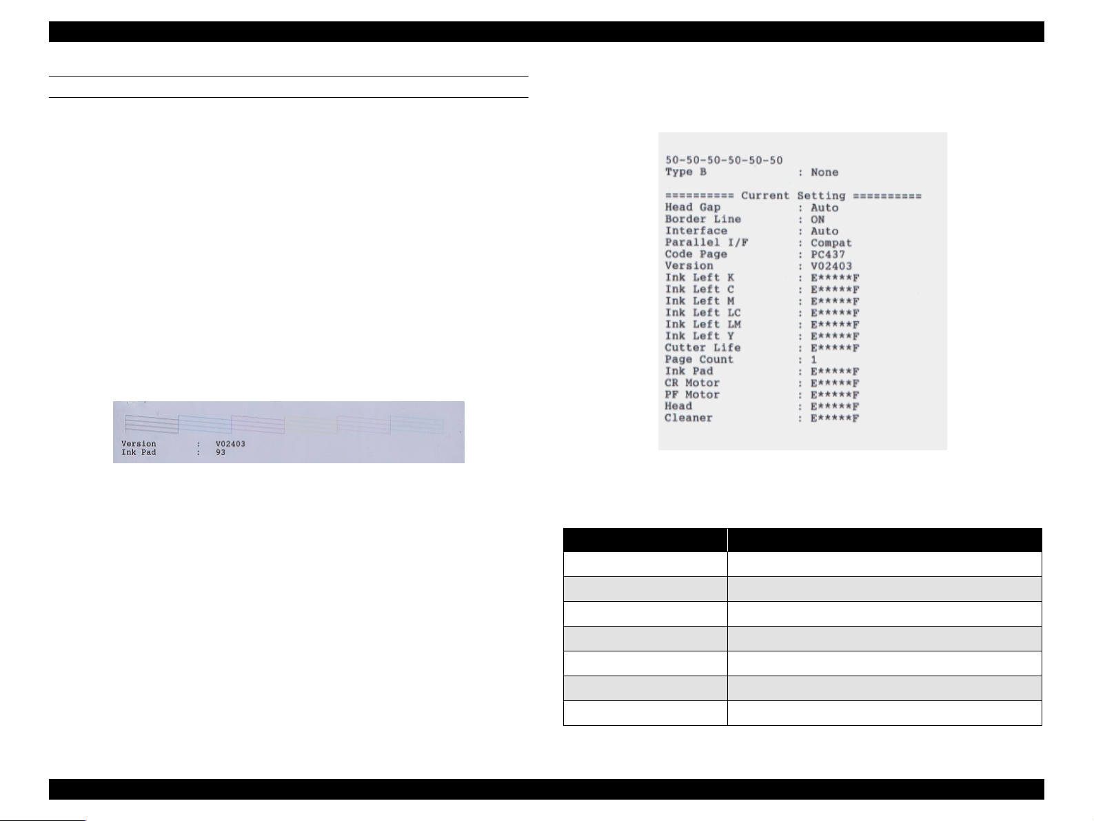
In nozzle check pattern printing, the following data are printed. The printing
size is approximately 9 cm (W) x approximately 3 cm (H).
o Nozzle Check Pattern
o Firmware Version (V0xxxx)
o Waste Ink Counter (xx%) (Waste ink counter remaining capacity %)
Figure 1-5. Nozzle Check Pattern Printing Results
version), Each Ink Life, Cutter Life, Page Count (total printed sheets
count), Ink Pad (Waste Ink Life), CR Motor (CR Motor Life), PF Motor (PF
Motor Life), Head (Head Life), Cleaner (Cleaning Unit Life).
Figure 1-6. Status printing result
In status sheet printing, the following data are printed. The printing size is
approximately 10 cm (W) x approximately 13 cm (H).
o Printer ID (= Head ID xx - xx - xx - xx - xx - xx)
In xx, the parameters stored in NVRAM are printed out in decimal
numbers.
o The order, from the left to right, is K - C - M - Y - Lc - Lm.
o Type B Interface Connection Condition
o The following printer settings
Head Gap, Border Line (perforation line), Interface (receiving settings),
Parallel Interface (Receiving Speed), Code Page, Version (Firmware
Display message Meaning
VERSION Shows the firmware version.
INK LEFT-C Shows the amount of remaining ink - Cyan
INK LEFT-M Shows the amount of remaining ink - Magenta
INK LEFT-LC Shows the amount of remaining ink - Light Cyan
INK LEFT-LM Shows the amount of remaining ink - Light Magenta
INK LEFT-Y Shows the amount of remaining ink - Yellow
INK LEFT-K Shows the amount of remaining ink - Black
Table 1-22. Printer Status Menu
Product Description Control Panel 30
Page 31

EPSON Stylus Pro 9500 Revision A
Table 1-22. Printer Status Menu (continued)
Display message Meaning
CUTTER LIFE Shows the remaining useful life of the cutter
TOTAL PRINTS Shows the total number of printed documents
WASTE INK Displays the CR motor life.
CR MOTOR Displays the PF motor life.
PF MOTOR Displays the head unit life.
HEAD UNIT Displays the head unit life.
CLEANING UNIT Displays the maintenance kit life.
See the following table concerning the display format for each item.
o Version
This is always displayed in 6 digits. Example: V00705
o Ink Life
Table 1-23. Remaining Ink Level Display
Remaining Ink Panel Display Ink Remaining
E*****F Off 100 ~ 81% remaining
E****F Off 80 ~ 61% remaining
Table 1-24. Cutter Life & Other Displays
Remaining Ink Life
E*****F 100 ~ 81% remaining
E****F 80 ~ 61% remaining
E***F 60 ~ 41% remaining
E**F 40 ~ 20% remaining
E*F 20% ~ 1% remaining
E Less than 1% remaining
Note 1) When the remainder on the cutter life counter becomes 0%, it does not result in a fatal
error since this is only a guideline. The cutter life counter is initialized by the “Cutter
Replacement Operation.”
Note 2) When the waste ink counter becomes less than 1%, a maintenance error occurs. If it
reaches 0%, a Service Call error occurs. The counter is reset in “Maintenance Mode 2”
when the waste ink pad replacement operation is performed.
Note 3) When remainder on the CR motor life counter becomes 0%, a fatal error is displayed.
Concerning the PF motor, head units and cleaning unit, there is no error display. The CR
motor life counter is reset in “Maintenance Mode 2.”
E***F Off 60 ~ 41% remaining
E**F Off 40 ~ 20% remaining
E*F Off 20% ~ Up to just before near end
nn% Blinking Near end up to just before ink end
0% Lights up Ink End
Note 1) When this counter becomes 0%, the LED lights up and the “Ink End” message is displayed
in the LCD.
Note 2)The ink consumption counter is reset when the ink cartridge is replaced.
o Printed Page Count
The total number of sheets printed is displayed by a decimal number with a
maximum of 6 digits.
o Cutter Life and Other (Motors, ink pad, heads, cleaning unit)
Product Description Control Panel 31
Page 32

EPSON Stylus Pro 9500 Revision A
CUTTER REPLACEMENT MENU
The following table includes the steps/messages that must be followed to
replace the cutter.
Each type of setting can be accomplished by operating the following panel
buttons.
o Cutter Replacement Menu Selection: See the panel setting menu
procedure.
o Cutter Replacement: “Paper Source” button
o Changing Setting Values: “+” or “–” button
o Setting the Set Values: “Enter” button
o Mode End: “Pause” button
Table 1-25. Cutter Replacement Messages
Display Mes sage Item Notes
CUT.REPLACE EXEC. Prepare a replacement cutter and
OPEN LOWER COVER - Open the front cover.
REPLACE CUTTER -
CLOSE LOWER COVER -
In this mode, if cutter replacement is carried out, the “Cutter Life” counter in the
print status menu is reset.
Remove the old cutter and install a
new one.
Close the front cover. The printer is
ready.
Product Description Control Panel 32
Page 33

EPSON Stylus Pro 9500 Revision A
GAP ADJUSTMENT MENU (BI-D ADJUSTMENT MENU)
Table 1-26. Gap Adjustment Menu
The paper thickness setting, Bi-D, gap (adjustment of the Bi-d deviation
between the left and right heads), and printing of the adjustment pattern as well
as adjustment are executed in the gap adjustment menu.
Each setting is made by operating the following panel buttons. If you select the
Gap Adjustment Menu, you cannot proceed to selection of the other items
without performing the “Paper Thickness” setting. After setting the paper
thickness (using the Set button), the menu automatically changes to the
adjustment mode.
o Gap Adjustment Menu Selection See the panel setting menu
procedure.
o Item Selection “Paper Source” button
o Changing or Selecting Setting Values “+” or “–” button.
Display Setting Value Contents
Specify the paper thickness used in the gap
PAPER
THICK
ADJUST.
PATT.
#1 1-7-15 Bi-D Adjustment (240 cps, Normal dot, Left)
#2 1-7-15 Bi-D Adjustment (240 cps, Normal dot, Right)
#3 1-7-15 Bi-D Adjustment (240 cps, Normal dot, Left)
Standard
or
0.0 ~ 1.6 mm
Print All
#1-#6
adjustment in 0.1 mm units. Ordinarily, the printer is
used with the “Standa rd” specificati on, and in th is case,
the paper thickness becomes as follows: Paper
Thickness Detect ion Sensor detection results = I f [ON /
Thin Paper] : 0.2 mmIf [OFF / Thick Paper] : 1.2 mm
Specifies the gap a dju stm en t pa ttern to be pri nte d. (All
patterns or the desired pattern.)
o Setting the Set Value “Enter” button
o Mode End “Pause” button
#4 1-7-15 Bi-D Adjustment (240 cps, Normal dot, Right)
#5 1-7-15 Gap Adjustment 1 (240 cps, Normal dot)
#6 1-7-15 Gap Adjustment 3 (333 cps, Normal dot)
Note 1) Values with underlines show default values.
Product Description Control Panel 33
Page 34

EPSON Stylus Pro 9500 Revision A
o
Setting Method
1.3.3 Maintenance Call
1) Set paper.
2) Enter the Gap Adjustment Menu by the panel.
3) If the paper thickness is set on 0.2 mm or 1.2 mm by the panel, it is
recognized as being the same as “Standard.” If you are setting other values,
input the paper thickness for the paper you are using in 0.1 mm units, in
accordance with the paper’s specifications. The purpose for inputting the
paper thickness at the first is to enable the printing of a pattern right from
the first that is thought to be close to the correction value that is already
being maintained by the printer, and thus to reduce the number of times the
operation has to be repeated.
4) Select an adjustment pattern to print (either all or individually) and print it.
After printing, the adjustment value input menu for that pattern will be
displayed in the LCD.
5) Input the pattern No. for the printed pattern that has the smallest deviation
in each adjustment item displayed in the LCD.
6) Repeat steps 4) ~ 5) until adjustment of all the items has been completed.
Note 1) If you are carrying out gap adjustment printing, printing paper with the
following lengths is necessary.
n When selecting and printing 1 pattern:Approx. 7 cm.
n When selecting and printing all printing patterns (6 patterns): Approx.
40 cm.
Some of the mechanical units used in this printer have counters which count
down the remaining service life based on the proper service life for each unit,
and when the predetermined value is reached, a “Maintenance Call nnnn”
message is displayed. If this message is displayed, it indicates that the end of
the service life of the affected unit is nearing, so it is necessary to replace the
affected unit as soon as possible.
If this message is displayed, the “Print?” or “Printing” display message is
replaced with the “Maintenance Call nnnn” message, and after replacing the
affected part, it is not cleared but continues to be displayed until the counter is
cleared in “Maintenance Mode 2.”
In the Stylus Pro 9500, when the remaining capacity of the waste ink pad is
less than 1% only, the following maintenance call is displayed in the LCD.
Even if the maintenance call is displayed, it is treated as a warning and it is
possible to continue printing.
Table 1-27. Maintenance Call / Code List
Error Code Error Content
0100
If use of the printer is continued while this maintenance call message is being
displayed, the remaining capacity of the waste ink pad will reach 0%, then a
Service Call error, 00000100, will be displayed.
• Waste ink pad service life (less than 1% of capacity remaining)
Note 2) Always, in printing of each pattern, 1 block of 15 patterns is printed 6
times. Pattern No. 8 of the 15 patterns in one block shows the current
setting value.
Product Description Control Panel 34
Page 35

EPSON Stylus Pro 9500 Revision A
1.3.4 Service Errors
When “Service Req nnnnnnnn” appears on the LCD display, a fatal error
requiring a service technician has occurred. The nnnnnnnn indicates what
needs to be fixed to return the printer to a working state.
Table 1-28. Maintenance Call / Error Code List
Error Code Error Content
Waste ink pad service life Note 1)
00000100
00000101
00010000
00010001
00010002
00010003
00010004
00010005
00010006
00010007
00010008
00010009
0001000A
0001000B
0001000C
0001000E
0001000F
(Replacement of the specified part and clearing of the counter are
necessary.)
Ink supply tube w ear Note 2)(This is equivalent to us in g the printer
beyond the product’s service life, so an error is displayed in
considerat ion of damage due to ink supply tube wear . Therefore,
when this error occurs, the status of the ink supply tubes should be
checked.)
PF Motor/ encoder check error.
PF Motor / Motor out of synch.
PF Motor / Overcurrent
PF Motor / In Position Time Out
CR Motor / Encoder check error
CR Motor / Motor out of synch.
CR Motor / Overcurrent
CR Motor / In Position Time Out
Servo interrupt WDT time out error
System interrupt WDT time out error
CR home position sensor failure
PF home position sensor failure
Head slide (SLID) home position sensor failure
Cover sensor failure (01)
CR Motor / PWM output abnormal
Table 1-28. Maintenance Call / Error Code List
Error Code Error Content
00020000
00020001
00020002
00020003
00020004
00020005
00020006
00020007
00020008
00020009
0002000A
0002000B
0002000C
10000004
10000006
10000009
1000000A
1000000B
Note 1) The following parts should be replaced and the relevant service life
counter cleared in “Maintenance Mode 2.”
[Replacement Parts]: “Maintenance Kit Stylus Pro 9500 (Part Code
Counter Clear: (Clear the counters in “Maintenance Mode 2”
“Waste Ink” Initialization
“Cleaning” Initialization
NVRAM error
NVRAM SUM Error
00020002
SRAM Check Error
DRAM Check Error
Vector Registration Error
CGRAM Error
Operation Code Error
DMA Error
Flash Memory SUM Error
CPU ROM Error
Insufficient Internal Memory Error
Review Error
CPU Vector 4 / General improper command issued.
CPU Vector 6 / Slot improper command
CPU Vector 9 / CPU address error
CPU Vector 10 / DMAC / DTC address error
CPU Vector 11 / WDT time out error
1058463)”
(Next page).)
000100010
PF Motor / PWM output abnormal
Product Description Control Panel 35
Page 36

EPSON Stylus Pro 9500 Revision A
Note 2) When this error occurs, check the condition of the ink supply tubes.
Even if there is no problem, it should be recommended to the user
that the parts comprising the CR System periodic replacement parts
kit, which is scheduled for introduction be replaced. If the printer is to
be used until CR system periodic replacement parts kit parts are
replaced, carry out “CR Motor Initialization” in “Maintenance Mode 2”
and cancel the error.
Product Description Control Panel 36
Page 37

EPSON Stylus Pro 9500 Revision A
1.3.5 Service Related Printer Settings
When the printer is not functioning properly, there are three modes that help
you detect what is wrong and can help you fix the problem. These modes are
“Maintenance Mode”, “Maintenance Mode 2”, and “Self-Diagnostic Mode”. To
enter a mode, press and hold down the appropriate button (described below)
while turning on the printer.
CAUTION
The following explanations regarding control panel service
functions and for service and support purposes only, none
of this information is to be shared with the end user.
MAINTENANCE MODE
Start Button: Turn the Power switch On while pressing the
o
“Pause” button.
o Setting Item Selection: “Paper Source” Button
o Changing Setting Values: “Setting Value +” or “Setting Value –” Button
o Setting the Set Values: “Enter” Button
o Setting End: Power ON/OFF
o Power-on button: Pause
Message Item Explanation
This prints out print data transferred
to the printer in hexadecimal form. 16
data items per line are displayed and
in addition, an ASCII character
corresponding to those data is
printed on the right side. If there are
HEX DUMP PRINT
no characters, such as print or control
codes, which correspond to the data,
a “.” (period) is printed. The panel
settings cannot be set while the
printer is in this mode. To end this
function, first stop printing by
operating the Pause button, then turn
the power switch off.
ENGLISH
The language displayed in the LCD
screen can be select English, French,
Italian, German, Spanish,
Portuguese.
LANGUAGE
FRENCH
ITALIAN
GERMAN
SPANISH
PORTUGUE
This selects M/W operation in the 720
x 720 dpi mode. A is the operating
MW7
A
B
mode that reduces banding in Bi-D
printing. B is the Stylus Pro 9000 /
7000 720 dpi x 720 dpi
interchangeable operating mode.
Note 1): Settings with underlines in the table show default values.
Product Description Control Panel 37
Page 38

EPSON Stylus Pro 9500 Revision A
Note 2): During HEX dump execution, the message “HEX MODE” is
displayed.
Note 3): If you are using the Stylus Pro 7000 to print in the single color mode
at 720 x 720 dpi, if banding is prominent, selecting this mode may
possibly reduce banding.
MAINTENANCE MODE 2
Start Button:Turn the Power switch On while pressing the following panel
o
buttons to start.
n “Paper Source Button” + “Cut / Eject Button” + “Paper Feed –
Button”
o Setting Item Selection:“Paper Source” Button
o Changing Setting Values:“Setting Value +” or “Setting Value –” Button
o Setting the Set Values:“Enter” Button
o Setting End:Power ON/OFF
This mode can be roughly divided into the following 3 items.
Table 1-29. Maintenance Mode 2 Setting Items
Item Panel Display
Counter Display Menu VIEW COUNTERS MENU
Counter Initialization Menu CLEAR COUNTERS MENU
Adjustment, Setting Menu SERVICE CONFIG MENU
For each major item, see the following page.
o Counter Display Menu
The items displayed in the Maintenance Mode 2 “Counter Display Menu” are
shown below.
Table 1-30. Counter Display Menu
Item Panel Display Setting Value
Remaining Ink (K) counter
Value Display
Remaining Ink (C) counter
Value Display
Remaining Ink (M) counter
Value Display
Remaining Ink (LC) c ounter
Value Display
INK K 0~4294967295 (Decimal number)
INK C 0~4294967295 (Decimal number)
INK M 0~4294967295 (Decimal number)
INK LC 0~4294967295 (Decimal number)
Product Description Control Panel 38
Page 39

EPSON Stylus Pro 9500 Revision A
o
Table 1-30. Counter Display Menu
Counter Initialization Menu
Item Panel Display Setting Value
Remaining Ink (LM) cou nter
Value Display
Remaining Ink (Y) counter
Value Display
Cutter Life Counter Value
Display
Total Printed Sheet Counter
Value Display
Waste Ink Counter A Val ue
Display
Waste Ink Counter B Val ue
Display
CR Motor Service Life
Counter Value Display
PF Motor Service Life
Counter Value Display
Head Unit (K) Service Life
Counter Value Display
Head Unit (C) Service Life
Counter Value Display
Head Unit (M) Service Life
Counter Value Display
INK LM 0~4294967295 (Decimal number)
INK Y 0~4294 967295 (Dec imal number)
CUTTER 0~4294967295 (Decimal number)
TTL PAGES 0~4294967295 (Decim al number)
WAST INKA 0~4294967295 (D ecimal number)
WAST INK B 0~4294967295 (Decimal number)
CR MOTOR 0~4294967295 (Decimal number)
PF MOTOR 0~4294967295 (Decimal number)
HEAD K 0 ~4294967295 (Decimal number)
HEAD C 0~4294967295 (Decimal number)
HEAD M 0~4294967295 (Decimal num ber)
The items that can be initialized in the “Counter Initialization Menu” in
Maintenance Mode 2 are shown below.
Table 1-31. Counter Initialization Menu
Item Panel Display Setting Value
Initializes NVRAM / Ink System /
Mechanism Counters.
Initializes NVRAM contents (Panel
setting information, Bi-D and Cap
Adjustment parameters).
Timer Setting Value Initialization INIT.TIMER EXEC.
CR Motor Service Life Counter
Initialization
PF Motor Service Life Counter
Initialization
Head Unit Service Life Counter
Initialization
Cleaning Unit Service Life Counter
Initialization
Total Printed Page Count Counter
Initialization
Ink Level Counter Initialization INIT.INK EXEC.
Waste Ink Capacity Counter Initialization INIT.WA INK EXEC.
INIT.ALL EXEC.
INIT.NVRAM EXEC.
INIT.CR MTR EXEC.
INIT.PF MTR EXEC.
INIT.HEAD EXEC.
INIT.CLEANER EXEC.
INIT.TTL PR EXEC.
Head Unit (LC) Service Life
Counter Value Display
Head Unit (LM) Service Life
Counter Value Display
Head Unit (Y) Service Life
Counter Value Display
Cleaning Unit Life Counter CLEANER 0~4294967295 (Decimal number)
HEAD LC 0~4294967295 (Decimal number )
HEAD LM 0~4294967295 (Decimal number)
HEAD Y 0~4294967295 (Decimal number)
Product Description Control Panel 39
Page 40

EPSON Stylus Pro 9500 Revision A
o
Adjustment Menu
SELF-DIAGNOSTIC FUNCTION MODE
The items that can be initialized in the Counter Initialization Menu in
Maintenance Mode 2 are shown below.
By turning the Power switch ON while pressing the following panel buttons, the
self-diagnostic mode is started.
Table 1-35 List of Adjustment Menu Items
o Paper Feed – Button + Cut / Eject Button + Cleaning Button
Table 1-32.
Item Panel Display Setting Value
Right Head Bi-D Offset Setting#1
\(Normal dot) Note 2)
BID OFFSET #1 -4~0~4
This mode is used in adjustment work, etc. when carrying out major parts
replacements. For details, see Chapter 5, “Adjustments.”
Ink Lavel Detection Note 3) DET.ECT INK LABEL
MW 2 Feed Balance Note 4) MW 7 BALANCE -31~0~+31
ON
OFF
Note 1): Settings with underlines show default values.
Note 2): This sets the desired offset the adjustment value in Bi-D Adjustment
Pattern #3, set by the user. This mode is a function for reducing
irregular color that occurs in the 720 dpi x 720 dpi and 1440 dpi x 720
dpi printing modes due to setting of the desired offset with respect to
the adjustment values for Bi-D adjustment values (Bi-D adjustment
pattern No. #3) for these printing modes. However, since there are
cases where there is no effect even when the desired offset is set in
this function, adequate caution should be exercised when changing
the setting values.
Note 3): This sets whether the sensor which detects the I/C type identifier on
the I/C label will detect it or not.
Note 4): If microbanding, which occurs in the 720 x 360 dpi mode and the 720
x 720 dpi mode actually occurs, this reduction function acts to reduce
banding somewhat when this setting is changed. However, there may
not be any effect even if the setting is set in the desired value by this
function, so exercise caution when changing the setting value.
Product Description Control Panel 40
Page 41

EPSON Stylus Pro 9500 Revision A
1.3.6 Firmware Update
The firmware is written to the Flash ROM on the printer’s main board. Thus, if
the main board has had to be replaced due to repairs, or if it is necessary to
upgrade the firmware version, and you are rewriting the firmware to the Flash
ROM, do so by either of the following methods.
CAUTION
UPDATING THE FIRMWARE VIA THE PC
n If the printer’s power is turned on immediately after
reloading the firmware, the initial filling operation may
start, so be sure to start the printer using the following
procedure.
1. Start the self-diagnostic function when the power is turned
ON.
2. Under “Diagnostics: Parameters”, select “Parameters:
Update.”
3. Select “Update: Ink Parameters.”
4. Select “Reset” under “Initial Filling Flag.”
5. Turn the printer’s power OFF, then turn it ON again.
n The firmware data file differs depending on the loading
method, so the correct file should be used.
• If through a PC: XXXXXXXX.IPL
• If through a PC Card: XXXXXXX.ROM
UPDATING THE FIRMWARE VIA MEMORY CARD
For details on this operation, see Chapter 5, "Adjustment".
1. Copy firmware data file to the PC card.
2. Remove the access cover on the rear of the printer (above paper guide U),
then insert the memory card (Flash memory card) where the firmware data
for reloading are recorded in the card slot (CN20).
3. Turn the printer’s power ON.
4. Reloading of the firmware will start and the following messages will be
displayed in order in the LCD panel.
Flash Erase
5. Turn the printer off, remove the memory card, and turn the printer back on.
CAUTION
→ Flash Write → Complete → Program Load End
Whichever method is used, if the update processing is
interrupted in the middle, (if the power goes off, etc.), it can
be recovered by repeating this operation.
1. Connect the affected printer to the PC. Use the parallel interface to make
the connection.
<Parallel Connection> : Effective only for Compatible mode connection
Turn the printer on while pressing the following buttons.
“Paper Source” + “Eject” + “Cleaning”
2. Send the proper firmware data file to the printer from the connected PC.
At the DOS prompt, input copy [filename] prn:”.
3. Reloading of the firmware will begin and the following messages will be
displayed in order in the LCD panel.
Flash Erase
4. Turn the printer off and back on.
→ Flash Write → Complete → Program Load End
Product Description Control Panel 41
Page 42

EPSON Stylus Pro 9500 Revision A
1.3.7 Jumper Settings
The factory default settings for jumper and DIP switch on the Main Board
(C277MAIN) are as follows.
Table 1-33. Jumper Settings
Type Number Setting
Jumper JP1 Shorted
Jumper JP2 Shorted
DIP-SW SWD1 “1” (1-4) OFF (Open)
DIP-SW SWD1 “2” (2-3) OFF (Open)
CAUTION
n The above jumper settings are used for factory settings
only, and should not be changed during servicing. These
jumper settings determine the matching of the firmware,
CPU and ASIC, etc., so if they are inadvertently changed, it
will become impossible to operate the printer.
n When installing the ASP board, the DIP-switch settings
should be changed as shown below. For details
concerning settings, see page 100.
•DIP-Switch Setting DIP-SW1 DIP-SW2
•ASP Board OFF OFF
•When board installed OFF ON
Table 1-34. Printer Status Menu (continued)
Display message Meaning
CUTTER LIFE Shows the remaining useful life of the cutter
TOTAL PRINTS Shows the total number of printed documents
WASTE INK Displays the CR motor life.
CR MOTOR Displays the PF motor life.
PF MOTOR Displays the head unit life.
HEAD UNIT Displays the head unit life.
CLEANER Displays the maintenance kit life.
See the following table concerning the display format for each item.
Table 1-34. Printer Status Menu
Display message Meaning
VERSION Shows the firmware version.
INK LEFT-K Shows the amount of remaining ink - Cyan
INK LEFT-M Shows t he amount of r emaining ink - Magenta
INK LEFT-LC Shows the amount of remai ning ink - Light Cyan
INK LEFT-LM Shows the amount of remaining ink - Light Ma genta
INK LEFT-Y Shows the amount of remaining ink - Yellow
INK LEFT-K Shows the amount o f remaining ink - Black
Product Description Control Panel 42
Page 43

OPERATING PRINCIPLES
CHAPTER
Page 44

EPSON Stylus Pro 9500 Revision A
2.1 Component List & Illustrations
This section explains the print mechanism and operating principles for the
EPSON Stylus Pro 9500.
2.1.1 Print Mechanism Components
The printer mechanism of EPSON Stylus Pro 9500 consists of the following
mechanism parts.
Table 2-1. Print Mechanism Components
Component Explanation
Carriage Assembly Carriage section:
o printheads (B head/C head)
o PG Motor
o Linear Encoder
o HP sensor
o PG sensor
o Paper Width sensor
o Paper cutter-drive component
Carriage guide rail section:
o CR Motor
Paper Feed Mechanism Paper feed rail:
o Grid roller assembly
o Secondary roller assembly (opposite the grid rollers)
o PF Motor (Rotary Encoder internal part)
o Paper Suction Fans
o P_FRONT Sensor (detects front edge)
o P_REAR Sensor (detects rear edge)
o Paper Thickness Sensor
o Paper Release-Lever Positi on Sens or
Cleaning Assembly
o Pump Assembly/Pump Motor
o Cap Assembly
o CR Lock Mechanism
Table 2-1. Print Mechanism Components
Component Explanation
Ink Delivery System I/C Holder Assembly
o Ink Cartridge Holder/Valve Mechanism
o I/H Lever Position Sensor
o Ink Cartridge Detect Sensor
o Ink Low Sensor
o Ink ID Sensor
Other Cover Position Sensor (interlock switch)
Operating Principles Component List & Illustrations 44
Page 45

EPSON Stylus Pro 9500 Revision A
CARRIAGE COMPONENTS
Linear Encoder
Carriage
(Including the Print Heads, Paper width
sensor, cutter drive mechanism)
SLID Motor
(PG moving Motor)
Cover Open Sensor
(interlock switch)
Guide Rail
HP Sensor/
Encoder
CR Lock
Mechanism
CR Motor
SLID Home
Position Detecting
Sensor
(PG home position
detecting sensor)
PAPER FEED PATH & COMPONENTS
PF Rotary
Encoder &
Encoder
Sensor
Paper
Suction
Fans
PF Motor
Grid Roller
Assembly
P-Front Sensor
Roll Paper
Holders
Secondary Roller Assembly
Paper Release Lever
P-Thick Sensor
P-Rear
Sensor
Figure 2-1. Carriage Components/Main Parts
Figure 2-2. Paper Feed Components/Main Parts
Operating Principles Component List & Illustrations 45
Page 46

EPSON Stylus Pro 9500 Revision A
INK SYSTEM COMPONENTS
F Box (L)
Waste Ink Pads
ELECTRICAL CIRCUIT BOARDS
Power Supply Board
I/H Assembly
Main Board
(C277MAIN)
Control Panel
Relay
Board
Pump Assembly
Cap Assembly
CR Lock
F Box (R)
Waste Ink Pads (R)
Figure 2-3. Ink System - Main Parts
Figure 2-4. Electrical Circuit Boards
Operating Principles Component List & Illustrations 46
Page 47

EPSON Stylus Pro 9500 Revision A
2.1.1.1 Carria ge Mechanism
CR GUIDE RAIL
To print on paper as wide as B0 Wide, the printhead carriage must be more
stable and must travel further than the usual carriage. To make the printheads
more stable, EPSON added the CR Guide Rail to the SP 9000.
Every EPSON ink jet printer until now has used a carriage guide shaft to
stabilize the carriage during printing and horizontal movement. SP 9000 does
away with the carriage guide shaft and relies on the printer frame for its
stability.
The CR motor uses a DC motor to move the carriage, and the Linear Encoder
determines the lateral position of the carriage by counting the shaded areas of
the plastic Step Ruler (timing fence). See Figure 2-5 below. The Linear
Encoder reads the shaded stripes to determine the position of the carriage as
well as the carriage speed, and this data is sent to the software servo. To allow
for the extra distance the carriage must travel during printing, the rubber timing
belt has been changed to a belt made from steel.
The following sensors are used in combination with the CR Guide Rail
components:
o HP Sensor
This optical sensor activates when the CR Guide Rail flag (flag) enters the
space between the light emitter and the light receiver. The flag is located
just above the home position, and the HP sensor sends an “On” signal
when the carriage is in the home position.
o Linear Encoder
This encoder is mounted on the back of the carriage and outputs pulses
corresponding to the position of the slits in the timing fence that is
incorporated into the CR guide rail which are used for CR motor software
servo control and PTS (Print Timing Signal) generation. This linear
encoder has a 2-channel digital output format, with phase A and phase B,
and the resolution of each phase is 1/180 inch. Each phase is output so
that it deviates 1/720 inch from the other phase and if full edge output of
both phases is used, the minimum resolution is 1/720 inch. The CR moving
direction is monitored by the CPU through the combination of the phase A
and phase B output waveforms.
Carriage
HP Sensor
Linear
Encorder
CR Guide Rail Flag
(Projected Area)
No HP Signal HP Signal
Step Ruler
(Plastic strip w/ Shaded striper)
Carrige
Figure 2-5. Carriage Mechanism & CR Guide Rail
CR
MOTOR
Operating Principles Component List & Illustrations 47
Page 48

EPSON Stylus Pro 9500 Revision A
CARRIAGE UNIT CONFIGURATION
In this printer, a carriage holding and drive mechanism construction which
differs from previous models is used. The carriage configuration consists of the
following major part s.
o Base Carriage :1unit
o Sub-carriage :1unit
o Print Heads :2 units (Dark system, Light system heads)
o Slide Eccentric Cam, Slide Gear
The mounting position of the base carriage is maintained at a constant
distance with respect to the paper surface at all times. Consequently, in order
to enable changes in the gap between the paper print ing surfac e (platen
surface) and the head nozzle surface, a sub-carriage is mounted on the base
carriage to which the print heads are fastened.
The sub-carriage is mounted on the base carriage in a state where is can move
in the vertical direction with respect to the paper surface by means of the SLID
eccentric cam, which is driven via the SLID gear. Through this mechanism, the
construction is such that the print heads can move to the set gap position.
Vertical movement of the sub-carriage with respect to the paper surface is
possible only in the case that the carriage is in the home position (HP). At that
time, the SLID motor pinion gear (PG moving motor) and the SLID gear
mounted on the SLID eccentric cam shaft engage, and the SLID cam is driven
by the SLID motor’s rotation, causing the sub-carriage (including the print
heads) to be raised or lowered to the proper gap position.
The print heads used in this printer are the same as those used in the Stylus
Pro 5500 and Stylus Pro 9000, and the head mounting method on the subcarriage also has the same construction. Therefore, if the print heads are
removed or installed, or replaced, it is necessary that the respective
inclinations and of the dark system head/light system head in the horizontal
direction (carriage scanning direction) and the light system head nozzle height
with the dark system head nozzle position as the reference in the vertical
direction (paper transport direction) be set with the adjustment lever. For
details, see Chapter 5, “Adjustments.”
Carriage
PG Gear
PG Cam
Printhead
Bearings
PG Slide Gear
Subcarriage
(printhead slots)
Figure 2-6. Carriage Mechanism & CR Guide Rail
(View from the printer’s right side)
CR Guide Rail
(frame span)
Operating Principles Component List & Illustrations 48
Page 49

EPSON Stylus Pro 9500 Revision A
CARRIAGE DRIVE MECHANISM
Driving of the carriage is accomplished using a DC motor which is controlled a
software servo through the means of a linear encoder. Basically, in the control
circuit, the torque calculation processing necessary for motor drive based on
carriage drive commands (position commands) is carried out and the motor is
excited and driven by the PWM output. Then the carriage position movements
executed by motor drive are fed back by signals generated by the linear
encoder as carriage position information and moving speed information for the
position commands and the carriage is controlled so that it moves at a constant
velocity.
o Print Control
Carriage drive speeds i print operations are as shown below.
Table 2-2. Carriage Speed
Print Mode Carriage Speed Head Drive Frequency
180 dpi (1 dot printing)
180 dpi (2 dot, 4 dot printing)
360 dpi (1 dot printing)
360 dpi (2 dot printing)
720 dpi (1 dot printing)
720 dpi
(1 dot 2 pass FOL printing)
33.3 IPS 6.0 KHZ
24 IPS 4.2 KHZ
24 IPS 8.6 KHZ
24 IPS 8.6 KHZ
24 IPS 17.3 KHZ
33.3 IPS 12 KHZ
o Stop Control
Carriage stop control is executed at the point when acceleration - constant
velocity - deceleration control processing is completed and is controlled by
position control through the software servo and a stabilization time (in
position time) at the stop position.
o CR Motor Trouble Detection
If the difference between the specified position given to software servo
control and the current carriage position read by the linear encoder
exceeds the specified number of pulses generated, a fatal error (CR Motor
out of Synch: Service Call 00010005) occurs.
1440 dpi
(1 dot 2 pass FOL printing)
1440 dpi
(1 dot 4 pass FOL printing)
24 IPS 17.3 KHZ
33.3 IPS 12 KHZ
Printing operations can be executed at the point when the carriage has
traveled 10 mm at a stable constant velocity after acceleration control.
Operating Principles Component List & Illustrations 49
Page 50

EPSON Stylus Pro 9500 Revision A
PAPER WIDTH DETECTION SENSOR
This sensor is mounted on the sub-carriage and detects the paper’s left and
right edge positions, identifying the paper width and judging if the paper is
skewed.
If it recognizes that there is paper present, its output voltage is raised and if it
recognizes that there is no paper present, its output voltage drops.
Table 2-3. Paper Width Detection Sensor Detection Modes
Paper Output Voltage
Present Voltage rises.
Not Present Voltage drops.
Paper Width Detection Sensor
Carriage
Paper Right
Edge Detection
Paper Left
Edge Detection
HP Side
Reverse HP
Side Scanning
Paper
Reverse HP Side
HP Side
Scanning
HP Side
Figure 2-7. Carriage Unit Paper Width Detection Sensor
A reflective type photosensor is used and the paper edge (paper present or
not) is judged by the 10-bit A/D converted value output by the sensor.
Detection of paper skew occurs in the following case and causes the message
“Set the paper correctly.” to be displayed in the LCD.
n If the front edge and back edge of a cut sheet are skewed more than 3
mm left to right.
Operating Principles Component List & Illustrations 50
Page 51

EPSON Stylus Pro 9500 Revision A
PG SETTING MECHANISM
In order to maintain the distance between the print head nozzle surface and the
paper constant in correspondence with the thickness of the paper used, a
mechanism is incorporated into this printer’s carriage which enables the print
head position to be set in 3 stages in the height direction as viewed from the
paper surface. The PG home position is detected by the LID home position
detection sensor mounted on the right frame and the SLID gear.
A reflective type photosensor is used in the SLID home position detection
sensor, and this detects the position of the notch in the SLID gear and make
that the home position.
The mechanism is configured so that when the sub-carriage is in the lowest
position, the sensor’s output is “OFF,” and the point when, during the detection
operation, the head drops down from its position after rising up, and the
sensor’s output changes from “ON” to “OFF,” is recognized as the mechanical
PG home position (PG = small).
Changes in the PG value from the PG home position are implemented by the
following operation
o PG home position → SLID motor pinion gear rotates CCW (Note) → SLID
gear
→ SLID gear shaft rotates CCW → SLID eccentric cam rotates CCW
→ Sub-carriage modes up (PG becomes wider).
Note): CCW rotation is the rotational direction shown if you are looking from
the printer’s right side.
The SLID eccentric cam is eccentric in 3 stages and the following 3 stages of
PG value setting are enabled by the number of SLID motor CCW rotation steps
in the above operation.
Table 2-4. SLID Home Position Detection Sensor Detection Mode
PG Value
Small (1.4 mm)
Medium (2.3 mm) Right ON 2.0 V or lower
Large (2.8 mm) Up (Left figure left) ON 3.0 V or higher
Slide Gear Notch
Position
Down
(Left figure right)
Sensor Output Output Voltage
OFF 2.0 V or lower
SLID eccentric
cam
Print head
Slide Gear
Sub CR unit
Figure 2-8. SLID Home Position Detection Sensor (PG Home
Position Detection Sensor)
Also, the actual PG value during printing is one of the following setting values
determined by the combination of the panel setting (Auto;, Widen), command
setting (default PG/PG large), and paper thickness detection sensor (thick
paper/thin paper) (Note).
Table 2-5. PG Position - Panel Setting / Paper Thickness
Panel PG Setting Command Setting
PG Large
Widen
Default PG
PG Large
Auto
Default PG
Note): See concerning the paper feed mechanism about the paper thickness
detection sensor.
Paper Thickness
Detection Sensor
Thick Paper PG Large
Thin Paper PG Large
Thick Paper PG Large
Thin Paper PG Medium
Thick Paper PG Large
Thin Paper PG Large
Thick Paper PG Large
Thin Paper PG Small
PG Position
Operating Principles Component List & Illustrations 51
Page 52

EPSON Stylus Pro 9500 Revision A
CUTTER SOLENOID
This solenoid is mounted on the side opposite the HP and the cutter for cutting
roll paper moves up and down by it. In order to prevent deviation due to the
paper curling up at the position where it is cut off during a cutting operation, the
cutting operation is performed in the following sequence.
Cutter
Carriage
solenoid
Paper
There are 2 methods used, which correspond to paper cutting conditions.
o 3-stage Cutting
n Cutting Conditions:
1. Cutting after printing and by resetting during printing.
2. Manual cutting during printing
3. Turning Auto Cut on after printing following Auto Cut Off, then manual cutting.
o Cutting Method
1st Stage:
From a position 60 mm to the left of the paper’s center, cut to a position 8
mm beyond the paper’s left edge (from right to left).
2nd Stage:
From a position 30 mm to the left of the paper’s right edge, cut to a
position 8 mm beyond the paper’s right edge (from left to right).
3rd Stage:
From a position 22 mm to the left of the paper’s right edge, cut to a position
68 mm to the left of the paper’s center (from right to left).
o 4-stage Cutting
n Cutting Conditions:
1. Paper is present at the top edge sensor, and when the paper set lever is lowered,
Cutter
manual cutting is done by pressing the “Cut/Eject” button.
2. Manual cutting while in the normal standby state.
3. Manual cutting after forward paper feed.
Figure 2-9. Carriage Unit - Cutter Solenoid
Operating Principles Component List & Illustrations 52
Page 53

EPSON Stylus Pro 9500 Revision A
n Cutting Method
1st Stage:
From a position 60 mm to the left of the paper’s center, cut to a position 8
mm beyond the paper’s left edge (from right to left).
2nd Stage:
From a position 60 mm to the right of the paper’s center, cut to a position 8
mm beyond the paper’s left edge (from left to right).
3rd Stage:
From a position 68 mm to the right of the paper’s center, cut to a position
40 mm to the right of paper’s center (from right to left).
4th Stage:
From a position 68 mm to the left of the paper’s center, cut to a position 48
mm to the right of the paper’s center (from left to right).
Operating Principles Component List & Illustrations 53
Page 54

EPSON Stylus Pro 9500 Revision A
CR LOCK MECHANISM
This mechanism uses a magnetic solenoid, and when the carriage is in the
standby state in the HP position, (CR motor excitation OFF), it locks the
carriage’s position. When the carriage is in the locked state, power to the
carriage is turned OFF, the actuator rises up and a projection engages with the
back surface of the carriage, binding the carriage. When carriage lock is
released, power to the carriage is turned ON, the actuator is withdrawn from
the carriage and the lock engagement is canceled.
Carriage Cover
Sub Carriage
(Fixed Hole)
CR Lock
Release
Lever
Figure 2-10. CR Lock Mechanism
Operating Principles Component List & Illustrations 54
Page 55

EPSON Stylus Pro 9500 Revision A
2.1.1.2 Paper Feed Mechanism
PF RAIL UNIT
The paper transport mechanism is made of the same extruded aluminum
material as the CR guide rail and consists of a grid roller (PF roller) mounted on
the PF rail and the pressurization and follower roller assembly mounted
opposite to it on the back of the CR guide rail. The grid roller (PF roller) in the
Stylus Pro 9500 differs from the grid roller (PF roller) in the Stylus Pro 9000, in
that there is only one. (In the Stylus Pro 9000, there are 3 fixed length rollers
lined up across the breadth of the printer, linked together with a coupling
construction, and fastened to the PF rail via bearings.)
A CD motor is used for the PF motor and this motor is software servo
controlled based on pulses output from an optical rotary encoder. In the Stylus
Pro 9000, an encoder sensor and loop scale are built into the PF motor, but in
the Stylus Pro 9500, the PF motor and encoder sensor/loop scale are separate
units, with the loop scale mounted at the left end of, and concentric with the PF
roller and the encoder sensor also assembled separately in the printer’s left
edge.
Driving of the PF roller is done by transmission to the PF roller through the
following channel.
o PF motor pinion gear _ Timing belt _ Reduction pulley _ Grid roller (PF
roller)
Suction fans are also mounted on the back side of the paper guide L (the
space in back of the paper guide L is divided into 3 cavities arranged side by
side across the width of the printer with one suction fan mounted in each
cavity), and by these fans pulling air from the back side of the paper and out
through the printer body, a suction force is applied to the paper guide L’s
surface which acts to stabilize paper travel (preventing it from lifting up).
Furthermore, the air volume is controlled by firmware (fan rotation duty control)
based on the printer’s operating state (when paper is set, during printing, etc.).
Grid Roller
Assembly
(PF Roller)
PF Rail
Timing Belt
Secondary Roller
Assembly
CR Guide
Rail
Speed-
Reduction
Gear
Platen
Subplaten
Paper
Paper Guide,
Lower
PF Motor
Back of the Printer
Front of the Printer
Figure 2-11. Paper Feed Mechanism - PF Rail Unit
Operating Principles Component List & Illustrations 55
Page 56

EPSON Stylus Pro 9500 Revision A
SENSORS
The following sensors and mechanisms are mounted in the paper transport
path.
o P-FRONT Sensor
A reflective type photosensor is used for this sensor, which is mounted on
the back of the paper guide L. This sensor’s detection state is used as the
reference point for the paper’s position control in the paper feed direction
(top of form during the paper set initialization operation, etc.). When there
is paper present, the voltage rises and when there is no paper, the voltage
drops.
o P-REAR Sensor
A reflective type photosensor is used for this sensor, which is mounted on
the back of the paper guide U. This sensor senses when the printer is out
of paper by detecting the rear edge of the sheet and starts the paper
setting operation (starting the suction fans, etc.) by detecting the front edge
of the paper when the paper is set. Just like the P-FRONT sensor, its
voltage rises when paper is present and drops when there is no paper.
o Paper Thickness Detection Sensor
A transmissive photosensor is used for this sensor, which is mounted on
the H top guide. A detection lever is mounted on the pressurization and
follower roller assembly on the HP side and the detection lever position,
which changes according to the thickness of the paper inserted between
the grid roller (PF roller) and follower roller is detected by this sensor.
o Paper Set Lever Detection Sensor
A transmissive type photosensor is used for this sensor. It detects the flag
position on the rear edge of the paper set lever mounted on the right side
frame. When the paper set lever is in the set state (Paper Set position), the
sensor’s output is “HIGH.”
P-REAR
Sensor
P THICK
Sensor
Paper Release
Lever
Table 2-6. Paper Thickness Detection
Paper Type Paper Thickness *1 Sensor output Output Voltage
Thin Paper 0.6 mm or less ON 0.7 V or higher
Thick Paper 0.7 mm or greater OFF 2.4 V or higher
Note) It is not definite which type of paper a sheet of paper with a thickness of
0.6 ~ 0.7 mm will be detected as.
P-FRONT Sensor
Paper Release Lever
Position Sensor
Figure 2-12. Paper Feed Mechanism - Sensors
Operating Principles Component List & Illustrations 56
Page 57

EPSON Stylus Pro 9500 Revision A
PAPER FEED CONTROL
In this printer, only roll paper and cut sheet paper can be used due to its friction
feed system. The printer’s status is detected by various sensors mounted
along the paper feed path and fed back to paper feed control.
o Paper Suction Fan Control
In order to provide assistance during setting of paper and stabilize paper
feeding during print operations, the three paper suction fans mounted
behind paper guide L pull o the paper from the back side of the sheet. The
fans are run at a constant velocity during printing, but when the paper is
set, the following control is carried out to improve setting characteristics.
Suction fan air flow control is carried out based on the paper sensing timing
of the P-Rear sensor and the P-FRONT sensor. Detailed control methods
are as shown below.
Paper Suction
Fan Control
Paper Set
lever in released
(up) state?
Is the
P_REAR sensoron?
(Is paper present?)
Run the suction fans at
low speed and attract
the paper.
Is the
P_FRONT sensor on?
(Is paper present?)
Run the suction fans
at high speed and
attract the paper.
Stop the suction fans.
End
Figure 2-13. Paper Suction Fan Control
Operating Principles Component List & Illustrations 57
Page 58

EPSON Stylus Pro 9500 Revision A
Table 2-7. Suction Fan Air Flow Control
State
Standby States other than the following
During paper setting (P-REAR sensor detected.)
During paper setting (P-FRONT sensor detected.)
During initialization with the paper set.
During printing (up to 30 mm of the front edge)
During printing (30 mm o f th e fr ont edge or more, but 40
mm or less of the front edge.)
During printing (after the first 40 mm of the front edge)
Cleaning with the paper set.
During paper cutting
o Paper Size Sensor Control - Left, Right Edge Detection
Sensing of the size of the paper set in the printer is done through the paper
left, right and front edge detection sequence.
Air Flow Duty (%)
Cut Sheet Roll Paper
00
50 50
80 80
100 100
10 10
50 100
100 100
100 100
--- 100
Paper Left/Right
Edge Detection
CR in home position?
Move the CR to an
empty suction position.
Move the CR to a
position where there is
paper.
Carry out periodic
flushing (in the cap).
Is there paper?
Move the CR to the
no paper position.
No paper?
Measure the no
paper level.
Move the CR to the
position where there
is paper.
Set the maximum moving distance and
while detecting the paper level, move
the CR to the position where the "No
paper" level is detected at the paper's
right edge.
No paper?
Right Edge Left Edge
Solid Line: Paper
Broken Line: Printable Area
Paper right edge
detection.
Set the maximum moving distance and
while detecting the paper level, move
the CR to the position where the "No
paper" level is detected at the paper's
Paper left edge detection.
No paper?
Return
left edge.
Error
Error Content:
(Set the paper correctly.)
Figure 2-14. Paper Size Sensor Control - Left, Right Edge
Operating Principles Component List & Illustrations 58
Page 59

EPSON Stylus Pro 9500 Revision A
o Paper Size Sensor Control - Front Edge Detection
Paper Front Edge
Detection
Carry out periodic
flushing (in the cap).
Stop the paper suction
fans.
Set the maximum backfeed
amount (200 mm).
Move the carriage to
a position 30 mm inside
the paper's left edge.
Is paper
present at the P_FRONT
sensor?
Set the maximum backfeed
amount / Backfeed the paper
to the position where the
P_FRONT sensor goes OFF.
Backfeed the paper a
further 40 mm.
Move the carriage
setting position.
Set the maximum backfeed amount
from the position where detection
starts, then backfeed the paper to the
paper's front edge "No paper"
detection position.
Does the
paper width detection
sensor detecting
"No paper"?
Detect the paper's front
edge.
Is the
paper's right top edge
being detected?
Move the carriage to a
position 30 mm inside
the paper's right edge.
This processing needs to be
carried out after setting the
paper level.
(after carryingout left and
right edge detection
processing)
Solid Line: Paper
Broken Line: Printable Area
Right top edge.
Left top edge.
o Paper Setting State Detection
If something abnormal is detected in the paper setting position check (left, right
edge and front edge detection) performed during initial processing when paper
is set in the printer, it results in an error with the message “Set the paper
correctly.” being displayed.
n Reference
The reference hole array for lining up the paper’s left edge on the paper
guide L (the right edge of the paper when viewing from the front of the
printer) is made the mechanical reference home position for judging the
paper position.
n Judgment Standard
Positional deviation of 10 mm or greater in the left and right directions from
the reference hole array (center) is regarded as an error.
o Paper Skew Judgment
The paper skew (inclination to the side) judgment is made with the left and
right edge detection position during form feeding of each printed page as
the reference. Therefore, if skewing occurs with a certain printed page,
after that page is printed, an error occurs at the front edge position of the
next page to be printed (the rear edge position of the previous page) and
the message “Paper is skewed” is displayed.
n Reference
Edge position detected during paper left, right edge detection.
n Judgment Standard
If there is deviation to the left or right exceeding 3 mm between the front
edge and rear edge of the paper (the front edge of the next page), it is
regarded as an error.
Error
Return
Error Content:
"Set the paper correctly."
Figure 2-15. Paper Size Sensor Control - Front Edge Detection
Operating Principles Component List & Illustrations 59
Page 60

EPSON Stylus Pro 9500 Revision A
2.1.1.3 Cleani ng Mechanism
This printer’s cleaning mechanism has the same mechanical configuration as
that in the Stylus Pro 5500 and Stylus Pro 9000. (However, it differs in its
component parts. See below for details.) The major component parts are
described below.
o Pump Assembly (Cleaner, head installation)
Suction of ink from the head nozzle through the cap is used to accomplish
cleaning. Through rotation of the pump wheel, and by pressing the ink
tubes connected to the cap, the internal pressure change accompanying
the change in the tubes’ internal volume causes the ink to be sucked up.
o Pump Drive Motor (Stepping Motor)
This is an exclusive motor that drives the pump assembly.
o Cap Assembly (Independent type for the dark system head and the light
system head)
This protects the print head nozzles when they are not operating and seal
off the head nozzle surfaces during the cleaning operation. The cap
assembly in the Stylus Pro 9500 uses new tubes to redu ce evapo ratio n o f
the moisture in the ink.
o F Box R
This is a receptacle for the ink that is discharged during flushing, with the
ink being discharged to the waste ink tank. In order to carry out flushing on
the side opposite the HP side, the F box L and waste ink tank (L) are also
provided separately. As for flushing in the Stylus Pro 9500, in order to
prevent mist from forming on the head nozzle surface during flushing and
in order to prevent the mist from condensing on the flushing box discharge
outlet, a construction with a new part (bell eater) added has been adopted.
Each of the above units is mounted on the sub-frame and fastened to the main
frame. (However, the F box L is a separate unit.) The CR lock mechanism is
also mounted on this sub-frame.
Operating Principles Component List & Illustrations 60
Page 61

EPSON Stylus Pro 9500 Revision A
2.1.1.4 Ink Supply Mechanism
The two ink cartridge holders each hold three cartridges, K, C, and M on one
side and Lc, Lm, and Y on the other side. The design of the holders makes it
quite easy to install and replace ink cartridges from the front of the printer. The
I/H Lever opens and closes the I/H door, and at the same time it changes the
angle of the Ink Cartridge Holder Assembly as shown in Figure 2-16, "Ink
Supply Mechanism". To prevent users from accidently installing a color ink
cartridge in the wrong slot, the cartridges have slightly different designs. Stylus
Pro 9000 dye ink cartridges have the same physical shape, so they can be
inserted in each color’s ink cartridge slot, but in order for the ink cartridge’s type
to be distinguished by the ink ID sensor, the message “Replace ink cartridge” is
displayed in the LCD panel and printing is not possible. See “I/H Assembly
Sensors” on page 64 concerning sensor details.
Another important feature of the ink cartridge holders is the ink valve, which is
located on the outer sides of the ink cartridge holders and shuts off the flow of
ink during printer transportation. The valve close under the following
conditions:
n The user turns the valve to the “CLOSE” position to transport the
printer.
n The I/H lever is lifted to the up/cartridge install position.
The ink flows out of the ink cartridges, through stainless steel pipes, through
ink tubes, and finally into the printheads.
I/H Lever
Ink Cartridge
Holder Assembly
Figure 2-16. Ink Supply Mechanism
Operating Principles Component List & Illustrations 61
Page 62

EPSON Stylus Pro 9500 Revision A
I/H ASSEMBLY SENSORS
The following sensors are located in the I/H compartment.
o I/H Assembly sensor
This optical sensor detects the whether the door is open and the I/H
Assembly is in the install position or the door is closed and the I/H
Assembly is in the print position.
When the I/H door is open, the signal = ON
When the I/H door is closed, the signal = OFF
o Ink Cartridge sensor
This mechanical sensor (microswitch) is built in all six ink cartridge slots.
When the I/C is installed, switch = closed
When the I/C is not installed, switch = open
o Ink Low sensor
This mechanical sensor (microswitch) is at the bottom of all six ink
cartridge slots and detects when ink is running out.
When the I/C is nearly empty, the switch = open
When the I/C is not low (normal), the switch = closed
o Ink ID sensor
This optical sensor is located at the side of all six ink cartridge slots and
detects the which market the cartridge is for. Although not implemented
currently, the sensor can also detect the type of ink (presently dye only)
and the type of special color (if new colors are introduced in the future).
The Ink ID sensor looks for the following marks on the ink cartridge.
Ink Cartridge
Figure 2-17. Ink Cartridge Holder Sensors
Ink ID Sensor
Front of the
Printer
Ink Cartridge Sensor
Rear of the
Printer
Ink Low Sensor
Market: No mark, white = Overseas/Global
Ink type No mark, white = dye-based ink
Special color No mark, white = N/A (may be available in future)
Operating Principles Component List & Illustrations 62
Page 63

EPSON Stylus Pro 9500 Revision A
2.1.1.5 Cover open sensor
To ensure proper paper feeding and to prevent paper jams, the front cover
must be closed during printing. There are two cover open sensors, one on
each side of the printer, that detect when the cover is open using an interlock
switch. When the cover is open, the relay that controls the current to the CR
motor and PF motor cuts off the flow of that current. The motors lose their
electromagnetized state when the current is cut off.
CR
Motor
PF
Motor
Driver
Driver
Front
Cover
Front cover
open
Cover Open
Sensor
C126/127
Figure 2-19. Cover-Open-Motor Control Circuit
Figure 2-18. Cover Open Sensor
The sudden loss of current to the motors can cause problems and may even
damage the motors or the printhead. To prevent this, a discharge from the
capacitor connected to the current circuit is used to slow down the current
before it is totally cut off. This process ensures that printing stops when the
cover is open without causing any damage to printer parts.
Operating Principles Component List & Illustrations 63
Page 64

EPSON Stylus Pro 9500 Revision A
2.1.2 Summary of Control Circuit Operations
This section summarizes the functions of the (C277MAIN) Main Board and the
controls used to operate the printer.
CN7
Control Panel
Flash mem./1MB
PC Card connector
Head data & c ontrol sig nals
Type-B Slot
Mac Serial I/F
Parallel I/F
Fixed
-Firmware
-Setting parameters
Head-drive wave
generation
Table 2-8. C277MAIN Board Main Components
Name/Code Location Function
CPU (C90A08CA)
SH7043
ASIC (E05B61AA) IC13
ASIC (TE7751) IC20
ASIC (uPD65802) IC32
DAC (M65530FP) IC37
IC8
32 bit RISC-CPU
o Clock speed = 33MHz
o 128KB PROM internal
1) Regulates print data
o Command handling
o Rasterizer (image data handling)
o Head drive regulation (DAC)
o Print timing regulation
2) Memory (DRAM/SRAM)
3) I/F Circuit Control
o Parallel interface (IEEE1284)
o Macintosh Serial interface
o Type-B
Regulates Motor
o Pump Motor
o PG Motor (PG setting)
o Fan (PS, Paper Suction)
Regulates motor (PWM regulation)
o CR Motor
o PF Motor
3 channel 10 bit DA converter
o head-drive voltage control
Flash Memory (1Mbyte)
o Save firmware
o Register setting parameters
EDO RAM
o 2Mbyte
Motor
drivers
Head-drive 3voltage
common driver
Flash Memory
(MBM29F400TC)
DRAM (EDO) IC18/19
IC1/2
o 16Mbtye (CN19 mounted SIMM)
CR
Motor
mechanism
Figure 2-20. C277MAIN Board-Circuit Block Diagram
Printer
PF
Motor
PG
Motor
Pump
Motor
Printheads (B/C)
SRAM (LC3564SM-
10)
Driver IC (L6203) IC33/35 CR/PF Motor Driver
Driver IC (LB1845) IC 30/31 PG/Pump Motor Driver
IC39
64Kbit SRAM
o External data ring buffer type
Operating Principles Component List & Illustrations 64
Page 65

EPSON Stylus Pro 9500 Revision A
2.1.2.1 Reset Circuit
The Reset-IC (IC7/BH6150F) used in the C277MAIN board has two built-in
reset circuits, each of which detects input voltage and power supply voltage
respectively as shown in the diagram on the right.
Pin 2 detects the voltage level of the head driver, using the input terminal of the
input voltage detection circuit. The voltage level to be detected is preset at
1.25V. When the preset voltage level is detected, the Pin 2 sends a reset
signal to reset the mechanism control circuit.
Pin 8 detects the voltage level of the logic power supply, using the input
terminal of the power supply voltage detection circuit. The voltage level to be
detected is preset at 4.2V. When the preset voltage level is detected, the Pin 8
sends a reset signal to reset the main logic circuits.
2.1.2.2 CR/PF Motor Driver Circuit
The EPSON Stylus Pro 9500 uses the DC servomotor to drive the CR and PF
motors. Therefore, the encoder is installed to detect the position, direction, and
speed of the carriage, and feedback from the encoder enables the software
servo control system to control the CR/PF motors.
The signal received from the Pin 60/61 in the IC32 enables the chopping
control system to control the output from the motor drive IC, and the output
from the Pin 10 in the motor drive IC (IC35/33) feeds back the output current
level to the IC32.
The Electro-magnetic Relay (LA1/LA2) is located on the power supply line for
the DC/PF motors, and it cuts off the power supply when the front cover is
open.
Figure 2-21. Reset Circuit
Figure 2-22. CR/PF Motor driver circuit
Operating Principles Component List & Illustrations 65
Page 66

EPSON Stylus Pro 9500 Revision A
2.1.2.3 Head SLID Motor Driver Circuit
The Head SLID Motor vertically adjusts the position of the printhead on the
carriage according to the thickness of the media in the printer. The motor is
driven by the constant current bipolar drive system, and the current supply to
the motor is controll ed by the PWM current control system. The 4-phase 48pole PM pulse motor is used for the drive motor, and it is driven by the W1-2
phase excitation.
Based on the preset data received from the IC20, the motor driver IC (IC31)
determines the current level to be output to the motor, and the motor is driven
by the drive phase switching signal which is input into the Pin 25/18.
2.1.2.4 Pump Motor Driver Circuit
The 4-phase 200-pole HB stepping motor is used to enable the ink system to
conduct ink absorption. The basic control method and the circuit configuration
are the same as those of the Head SLID Motor Driver Circuit.
Figure 2-24. Pump Motor driver circuit
Figure 2-23. HD_SLID Motor driver circuit
Operating Principles Component List & Illustrations 66
Page 67

EPSON Stylus Pro 9500 Revision A
2.1.2.5 Printhead Driver Circuit
The EPSON Stylus Pro 9500 uses the same printhead as that of the EPSON
Stylus Pro 5000 (both dark-color head and light-color head), and the basic
configuration of the driver control circuit is also the same.
Print data is rasterized on the memory (DRAM). Triggered by the LAT signal
(BHLAT, CHLAT), the IC13 reads the print data in the format and the order
according to the print mode, and transfers the data to the printhead (driver
circuit on the printhead) synchronizing with the clock signal (BHCLK, CHCLK).
The IC13 is equipped with the counter function, which keeps count of each
color’s data "1" being transferred to the printhead, and the accumulated count
is used to calculate the ink consumption.
The waveform signal is processed at the IC13. Triggered by the input of the
PTS signal from the CPU (IC8), the waveform signal is input into the DAC in
the IC37 as 10-bit data, synchronizing with the clock signal (20mHz). The DAC
then converts the head driver voltage waveform data to analog data, and
outputs it to the trapezoid waveform generation circuit (common driver).
The driver circuit on the printhead (nozzle selector) receives the serial data on
nozzle selection ("H" level = printing nozzle / "L" level = non-printing nozzle)
from the IC13. The circuit then latches the data to the data latch using the LAT
signal, and selects the printing nozzles and non-printing nozzles. Once the
nozzles are selected, the trapezoid waveform generation circuit (common
driver) generates the trapezoid waveform to fire ink. The NCHG signal
(BHNCHG, CHNCHG), which is input into the printhead from the IC13,
prepares all the nozzles for the next firing by applying slight vibrations during
the non-printing phase.
Figure 2-25. Printhead driver circuit
Operating Principles Component List & Illustrations 67
Page 68

EPSON Stylus Pro 9500 Revision A
2.1.2.6 Sensors
The output signal sent from each sensor of the EPSON Stylus Pro 9500 is
connected to each IC on the control circuit as shown in the diagram on the
right.
In order to process the detected results as analog signal, the following sensors
input the results into the analog port in the CPU (IC8) via comparator. The
analog signal is then converted to the digital signal by the CPU built-in ADC
(10-bit) and is compared with the standard value for state analysis.
o P_REAR Sensor
o P_FRONT Se nsor
o P_EDGE Sensor
Concerning these sensors, since it is necessary that the reference voltage
(threshold) be set at the proper level during AD conversion to match each
sensor’s characteristics, if the main board is replaced, or if the sensor boy is
replaced, it is necessary to adjust the level using the volume (variable resistor)
on the circuit board.
Also, the Thermistor inside the print heads detects the head internal
temperature, feeds it back to the CPU and carries out drive voltage correction
control to match changes in temperature.
Figure 2-26. Sensors
Operating Principles Component List & Illustrations 68
Page 69

TROUBLESHOOTING
CHAPTER
Page 70

EPSON Stylus Pro 9500 Revision A
3.1 Outline
This section describes how to diagnose printer errors as well as how to resolve
them. Troubleshooting is divided into the following categories.
o Troubleshooting using the error messages
o Troubleshooting based on printout
In addition to the above troubleshooting points, this section covers check
points as well.
3.1.1 Test Points
The following table lists the test points for electrical components.
Table 3-1. Test Points for Electrical Components
Component Standard
CR Motor Armature resistance: 10.0 ohm
PF Motor Armature resistance: 2.3 ohm
SLID Motor Coil resistance: 17.5 ohm
PUMP Motor Coil resistance: 3.9 ohm
Cutter Solenoid Coil resistance: 58 ohm
CR Lock Solenoid Coil resistance: 58 ohm
3.1.2 Troubleshooting Using the Error Messages
The EPSON Stylus Pro 9500 performs self-diagnostic tests using the data
supplied by its various sensors, and if an error is detected by one or more
sensors, a corresponding error message appears on the control panel display.
No matter what kind of error occurs, use the Error Message List for Service
Technicians table on page 70 or the General Error Message List table on page
71 to determine what and where the problem is, as well as where to look for
directions on fixing the problem.
o Errors that Require a Service Man
This shows an error state in which it is necessary for a service man to carry
out treatment accompanying checking and replacement of the relevant
parts.
o General Error
This shows an error state where the user himself can check and carry out
the needed treatment.
Table 3-2. Error Message List for Service Technicians
Error Code Description Refer to
MAINTENA
NCE REQ.
nn
0100
Waste Ink pads is almost full (less than 1%
remaining)
page 72
Troubleshooting Outline 70
Page 71

EPSON Stylus Pro 9500 Revision A
Table 3-2. Error Message List for Service Technicians
Error Code Description Refer to
SERVICE
REQ.
nnnnnnnn
00000100
00000101 Ink Tube worn out
00010000 PF motor encoder chec k error
00010001 PF motor out of step
00010002 PF motor overcurrent
00010003 PF in-position time-out
00010004 CR motor encoder check error
00010005 CR motor out of step
00010006 CR motor overcurrent
00010007 CR in-position time-out
00010008 Servo interrupt watc hdog time-out error
00010009 System interr upt watchdog time-out error
0001000A CR origin sensor malfunction
0001000C PG origin sensor malfunct ion
0001000D Cov er sensor malf unct ion (00)
0001000E Cover sensor malfunction (01)
0001000F CR motor PWM output error
00010010 PF motor PW M outp ut error
00020000 NVRAM error
00020001 Internal RAM check error
00020002 SRAM check error
00020003 DRAM check error
10000004 CPU vector 4 - General illegal instruction
10000006 CPU vector 6 - Slot illegal instruction
10000009 CPU vector 9 - CPU address error
1000000A CPU vector 10 - DMAC/DTC address error
1000000B CPU vector 11 - Watchdog time-out error
100000”” CPU vector 32~63
Waste Ink pads must be replaced
Remaining Capacity Zero
page 72
page 72
page 72
page 72
page 73
page 73
page 73
page 73
page 74
page 74
page 74
page 74
page 74
page 74
page 74
page 74
page 75
page 75
page 75
page 75
page 75
page 75
page 75
page 75
page 75
page 75
page 75
page 75
Table 3-3. General Error Message List
Error Type Message Refer to
Warning Ink Low page 75
ERROR Paper Out page 76
Load xxx Paper page 76
Load Paper page 76
Paper Jam page 76
Cover Open page 76
Paper Not Cut page 77
Paper Not Straight page 77
Reload Paper page 77
Push Lever Down page 78
Compartment Open page 78
Ink Out page 78
No Ink Cartridge page 78
Remove Paper page 79
Option I/F Error page 79
Troubleshooting Outline 71
Page 72

EPSON Stylus Pro 9500 Revision A
3.1.2.1 Errors that require a service technician
Here, the contents and treatment methods for each error that requires a
service man mentioned on the previous page are explained.
MAINTENANCE REQ. 0100
o Problem
The waste ink pads have absorbed 99% of their potential. The printer can
continue printing, but the “Maintenance Req. 0100” message appears
instead of the “Ready” or “Printing” messages.
o Solution
Replace the following parts and reset the ink counter
n Waste Ink Pads (right, left)
n F Box (right, left)
n Pump Assembly
n Cap Assembly
n Cleaner, Head
SERVICE REQ. 00000100
o Problem
The waste ink pads are completely full, causing a fatal error. The printer
stops printing.
o Solution
See the solution for Maintenance Req. 0100.
SERVICE REQ. 00000101
o Problem
A printer part has exceeded its useful life, and to prevent damage to other
parts as well as abnormal operations/printouts, an error occurs. This error
occurs when the CR Motor has reached 2.5 million passes, and this
indicates the Ink Tubes should be replaced due to excessive wear and
tear.
o Solution
To make sure the Ink Tube is not worn out, verify no part of the tube shows
wear, is loose, or leaks ink anywhere, especially the tube area between the
printheads and the ink pipes.
SERVICE REQ. 00010000
o Problem
PF motor encoder check error
The PF motor makes small revolutions clockwise and counter-clockwise.
When it turns, the printer checks the rotary encoder output signals to make
sure the motor is turning at the correct speed/distance. If there the encoder
doesn’t send the correct signal or output data, an error occurs.
o Solution
Make sure there is nothing blocking the grid rollers. If that does not solve
the problem, check the PF motor encoder connection. If there still is a
problem, try the following.
n Check and adjust the PF Belt tension
n Replace the PF motor
n Replace the Main Board
SERVICE REQ. 00010001
o Problem
PF motor out of step - the length of the PF motor internal encoder’s pulse is
too long or too short compared to the regular pulse. Self-diagnostic
Function: Check in “Inspection: Encoder.”
o Solution
Make sure there is nothing blocking the grid rollers. If that does not solve
the problem, check the PF motor encoder connection. If there still is a
problem, try the following.
n Check and adjust the PF Belt tension
n PF Motor encoder sensor mounting position deviation (See Chapter 5.)
n Replace the PF motor
n Replace the Main Board
Troubleshooting Outline 72
Page 73

EPSON Stylus Pro 9500 Revision A
SERVICE REQ. 00010002
o Problem
PF motor overcurrent - Feedback from the PF motor (IC35) driver’s 10-pin
output (sensor signal) indicates that the PF motor’s current is irregular.
o Solution
n Replace the PF motor
n Replace the Main Board
SERVICE REQ. 00010003
o Problem
PF in-position time-out - The in-position time is the amount of time the
printer waits to make sure the carriage is not moving when the carriage
comes to a stop. The rotary encoder is activate for the predetermined “inposition time” and if the encoder sends a pulse, this means the carriage is
moving even though it is supposed to be at a full stop, this generates an
error.
o Solution
n Replace the PF motor
n Replace the Main Board
SERVICE REQ. 00010004
o Problem
CR motor encoder check error
The CR motor makes small revolutions clockwise and counter-clockwise .
When it turns, the printer checks the encoder output signals to make sure
the motor is turning at the correct speed/distance. If the encoder doesn’t
send the correct signal or output data, an error occurs.
o Solution
Make sure there is nothing blocking the carriage. If that does not solve the
problem, check the CR motor encoder connection. If there still is a
problem, try the following.
n Check the plastic step ruler for soiled areas, obstructions, and damage
n Replace the encoder sensor
n Replace the CR motor
n Replace the Main Board
SERVICE REQ. 00010005
o Problem
CR motor out of step - the length of the CR motor’s pulse is too long or too
short compared to the regular pulse.
o Solution
Make sure there is nothing blocking the carriage. If that does not solve the
problem, check the CR motor encoder connection. If there still is a
problem, try the following.
n Check the plastic step ruler for soiled areas, obstructions, and damage
n Encoder sensor mounting position deviation (See Chapter 5.)
n Replace the encoder sensor
n Replace the CR motor
n Replace the Main Board
Troubleshooting Outline 73
Page 74

EPSON Stylus Pro 9500 Revision A
SERVICE REQ. 00010006
o Problem
CR motor overcurrent - Feedback from the CR motor (IC33) driver’s 10-pin
output (Sense signal) indicates that the PF motor’s current is irregular.
o Solution
n Replace the CR motor
n Replace the Main Board
SERVICE REQ. 00010007
o Problem
CR in-position time-out - The in-position time is the amount of time the
printer waits to make sure the carriage is not moving when the carriage
comes to a stop. The linear encoder is activate for the predetermined “inposition time” and if the encoder sends a pulse, this means the carriage is
moving even though it is supposed to be at a full stop, this generates an
error.
o Solution
n Replace the CR motor
n Replace the Main Board
SERVICE REQ. 00010008
o Problem
Servo interrupt watchdog time-out error due to motor-drive control related
error
o Solution
n Replace the Main Board
SERVICE REQ. 00010009
o Problem
System interrupt watchdog time-out error due to sensor-related error
o Solution
n Replace the Main Board
SERVICE REQ. 0001000A
o Problem
CR origin sensor malfunction - CR home position sensor malfunction
o Solution
Self-diagnostic Function: Check “CR Home Position” in “Inspection:
Sensors.”
n Replace the HP sensor
n Replace the Main Board
SERVICE REQ. 0001000C
o Problem
PG origin sensor malfunction (may indicate PG motor malfunction)
o Solution
Check the sensor surfaces for adhesion of ink or soiling, etc. which might
hinder sensor operation. If there is no troub le, and the error cannot be
canceled, check the SLID home position sensor (Self-diagnostic function:
Check “Head Slide” in “Inspection: Sensors.”)
n Replace the PG sensor
n Replace the Main Board
SERVICE REQ. 0001000D
SERVICE REQ. 0001000E
o Problem
Cover sensor malfunction - one or both cover open sensors (interlock
switch) located at either end of the cover shaft is malfunctioning.
n (00): right sensor (HP side)
n (01): left sensor
o Solution
Make sure the sensor(s) are properly installed. If that does not solve the
problem, check the cover open sensor connection. Self-diagnostic
Function: Check “Covers” in “Inspection: Sensors.”
n Replace the malfunctioni ng co ve r sen sor
n Replace the Main Board
Troubleshooting Outline 74
Page 75

EPSON Stylus Pro 9500 Revision A
SERVICE REQ. 0001000F
o Problem
CR motor PWM output error
o Solution
n Replace the Main Board
SERVICE REQ. 00010010
o Problem
PF motor PWM output error
o Solution
n Replace the Main Board
SERVICE REQ. 00020000 (NVRAM ERROR)
SERVICE REQ. 00020001 (INTERNAL RAM ERROR)
SERVICE REQ. 00020002 (SRAM ERROR)
SERVICE REQ. 00020003 (DRAM ERROR)
o Problem
Unusual condition detected.
o Solution
n Write down the error code, turn the printer off and back on again to
confirm whether the error recurs. If the same error recurs, replace the
Main Board.
n For “Service Req. 00020003” (DRAM error), replace the RAM-
SIMM(16MB) installed in CN19 and confirm whether the error recurs.
SERVICE REQ. 10000004 (CPU GNRL ILLEGAL INSTRCTNS)
SERVICE REQ. 10000006 (CPU SLOT ILLEGAL INSTRCTNS)
SERVICE REQ. 10000009 (CPU CPU ADDRESS ERROR)
SERVICE REQ. 1000000A (CPU DMAC/DTC ADDRESS ERROR)
SERVICE REQ. 1000000B (CPU WATCHDOG TIME-OUT ERROR)
SERVICE REQ. 100000## (CPU VECTOR 32~63)
o Solution
n Write down the error code, turn the printer off and back on again to
confirm whether the error recurs. If the same error recurs, replace the
Main Board.
n Send a different print job to make sure the error wasn’t due to electrical
noise or bad print data.
3.1.3 General Errors
This section describes the errors that can be solved by the user.
INK LOW
o Problem
An ink end sensor has detected that the corresponding ink cartridge is
almost empty (ever ink cartridge has an ink level gauge). It is possible to
print about 100% duty on B1 size paper with the remaining ink, but the
cartridge should be replaced as soon as possible.
If you re-install an ink cartridge that was detected as being in a “Near End”
state, the status will immediately go to “Ink Out”. Only install new
cartridges.
o Solution
Replace the ink cartridge.
CHECK
PO IN T
If for any reason you replace an ink cartridge before it
reaches the ink-low or ink-out state with a new ink
cartridge, you need to reset the ink counter using the
control panel and Maintenance Mode 2.
Troubleshooting Outline 75
Page 76

EPSON Stylus Pro 9500 Revision A
PAPER OUT
o Problem
n Paper is not loaded.
n The rear edge of roll paper has been detected.
n The print job using cut sheets is finished or the rear edge of cut-sheet
paper has been detected.
o Solution
n If paper has run out, remove the printer paper and load new paper. If
print data remains in the printer, the data will be printed.
n If this error occurs even though paper is properly loaded, there may be
something on the P-Rear sensor’s surface. Clean the sensor’s surface
(hole in the Paper Guide, Upper) with a clean, dry cloth.
CAUTION
Use a clean, dry cloth when cleaning sensors; never
use a wet cloth or soap.
LOAD XXX PAPER
o Problem
The selected paper source (according to the remote PP command) and the
paper type selected on the control panel do not match.
o Solution
Load the correct paper or change the panel setting to match the type of
paper loaded in the printer.
n If this error occurs even when the lever is down, in the Lock position,
there may be a problem with the Paper Release lever sensor. Check
the sensor operation, sensor connection, and board.
PAPER JAM
o Problem
A paper jam occurs when during printing, paper feeding, or paper cutting
the carriage is not able to move properly (due to paper catching on some
part). The printer determines a paper jam has occurred if the P-Front
sensor and P-Rear sensors are in the “on” state but the CR motor is out of
step or has overcurrent.
o Solution
n Check if the appropriate spindle is being used for the paper.
• Mat synthetic paper roll:
Use of a high tension spindle is recommended.
• MC image paper roll:
Use of a high tension spindle is recommended.
n If the paper that is involved in a paper jam is removed, the message
“Please start again.” will be displayed, so turn the printer’s power on
again.
n If the paper jam occurs again after the paper has been removed, check
around the carriage mechanism to see if there is some kind of
obstruction to carriage movement. If there is some kind of foreign
object, etc. present, remove it.
COVER OPEN
o Problem
LOAD PAPER
o Problem
While paper is loaded, the Paper Release lever was pushed up to the
Release position.
o Solution
n Make sure paper is loaded properly and push down the Release lever
Front cover is open.
o Solution
n If the cover is opened during carriage operation or during a cleaning
operation, etc., all mechanical operations are halted, so if it is left open
for a long period of time, it could have a bad influence on the print
head. Therefore, the cover should be closed rapidly.
to lock the paper in place.
Troubleshooting Outline 76
Page 77

EPSON Stylus Pro 9500 Revision A
n If this error occurs when the left and right sides of the front cover are
closed securely, the mounting position and operation of the cover open
detection sensor (interlock switch) should be checked.
CAUTION
n If the cover is opened during printing, the affected
pass will not be reprinted after r ecovery, so there will
be marks left on the printout at the affected portion.
n If you would like to open the cover during printing,
press the “Pause” button to interrupt the printing
operation, then open the cover . However, even in this
case, since the printing times will be different in the
area before and after the place where printing was
interrupted, irregularities in the print quality
(irregular color) will occur.
PAPER NOT CUT
o Problem
The paper that was supposed to be cut was not cut completely, or the
paper was cut but is still in front of the P-Front sensor.
o Solution
n Remove the cut paper if it is on or near the Front Cover and Lower
Paper Guide.
n Replace the cutter if it is worn out.
n If miscutting is occurring due to deviation in the paper cutter position,
carry out adjustment of the paper guide L installation position,
adjustment of the cutter mounting position, checking of the paper
cutting position and adjustment of the CR cover height. See Chapter
5.
PAPER NOT STRAIGHT
o Problem
This error occurs when the printer detects the front and rear edges to be
skewed (the paper is loaded at an angle/slant) by more than 3mm. If the
printer prints on paper that is loaded at a slant, the printer may print outside
of the printable area and may fire ink onto the platen. If this happens, the
next sheets loaded in the printer may have marred reverse sides.
o Solution
n Remove the paper loaded in the printer and properly reload it
according to the instructions in the user’s guide.
n For roll paper, the edges of the paper may not be lined up; (remove the
paper) and carefully squeeze the sides of the roll to make sure the
edges are lined up and flat.
RELOAD PAPER
o Problem
This error occurs when,
A) The front edge is loaded too far and the paper is not in the loading
position after it is reverse fed.
B) The paper was loaded in such a way that the left and/or right edge is
out of the printable area (due to mis-loading or because the paper is too
wide).
C) After printing has finished, the right or left edge is out of the area where
the cutter can cut the paper.
D) The loaded paper was longer than the selected paper, and the paper
was not fully ejected. (For example, roll paper is loaded in the printer but
cut sheet is selected on the control panel.)
E) A cutter error occurred after the paper was ejected.
Troubleshooting Outline 77
Page 78

EPSON Stylus Pro 9500 Revision A
o Solution
n A)~C) above
Properly reload paper. If the front edge of the paper is not straight and
clean, cut the paper.(If the paper is pulled back and set 60 mm or more
from the criterion line (hole), it will exceed the permissible amount of
backfeed (200 mm from the paper edge detection sensor position and
result in an error.)
n D)~E) above
Cut of the section of the paper that has ejected/protruded and reload
the rest of the paper. For paper that is automatically cut, lift up the
Release Lever (the “Load Paper” message appears), fix the position of
the paper, and lower the Release Lever. If you select you “Roll Paper/
Auto Cut” setting, you can cut off the protruding part of the paper using
the Cut button.
n If the error recurs even after reloading the paper, make sure the paper-
end sensor on top of the carriage is installed correctly and working
properly.
PUSH LEVER DOWN
o Problem
The printer is not able to continue paper feeding/initializing, printing, or ink
sequencing because the Release lever was moved to the Release
position. Or, the printer cannot begin printing because the lever is in the
release position.
o Solution
n Push down the lever. However, if printing was interrupted because the
lever was pushed to the release position and the paper shifted, the
print job may be marred.
n If the lever is down and this error still occurs, check the Release-Lever
position sensor.
COMPARTMENT OPEN
n Push the I/H lever down to the lock position.
n If the lever is down and this error still occurs, check the lever position
sensor.
INK OUT
o Problem
One or more ink cartridges have run out of ink, a near-end cartridge has
been reinstalled, or an unsupported ink cartridge has been installed.
o Solution
n Replace the empty ink cartridge.
CAUTION
When replacing an empty ink cartridge, always repl ace
it with a new ink cartridge; otherwise the printer
cannot determine how much ink remains.
n Make sure the ink cartridge is the proper type of cartridge for the
printer and the proper color for that slot.
n If the proper cartridge is installed and this error still occurs, check the
Ink-End sensor and the Ink ID sensor.
NO INK CARTRIDGE
o Problem
An ink cartridge is not installed or is not installed properly.
o Solution
n Install the proper ink cartridge in the empty slot.
CAUTION
When replacing an empty ink cartridge, always repl ace
it with a new ink cartridge; otherwise the printer
cannot determine how much ink remains.
o Problem
An Ink Holder (I/H) compartment door is open.
o Solution
n If the proper cartridge is installed and this error still occurs, check the
Ink-Cartridge sensor.
Troubleshooting Outline 78
Page 79

EPSON Stylus Pro 9500 Revision A
REMOVE PAPER
o Problem
Printer cannot perform cleaning because of thick paper. (The printheads
are too far away from the Cap Assembly.) This error occurs under the
following conditions.
n Thick paper is loaded when the periodic/timer cleaning operation is
supposed to begin.
n The printer attempts to print on thick paper when the periodic/timer
cleaning operation is supposed to begin.
n You turn on the printer and the thick paper is loaded.
n You attempt to perform a manual cleaning operation when thick paper
is loaded.
o Solution
n Remove thick paper and push the Release lever down. (This causes
the cleaning to operation to start and “Wait” appears on the display.)
After the cleaning operation is finished, “Paper Out” appears. Load
thick paper.
OPTION I/F ERROR
o Problem
An unsupported Type-B interface card is installed.
o Solution
Turn off the printer, remove the unsupported card, and install a supported
card.
3.1.4 Troubleshooting Based on Your Printout
This section describes the conceivable print quality problems that may occur
with this printer and the troubleshooting points for those errors.
Table 3-4. Print Quality Problems
Description Refer to
Dot missing page 79
Uneven printing/poor reso lution page 80
Smudged or marred printout on front side page 80
Smudged or marred printout on reverse side page 81
White/black banding page 81
DOT MISSING
When the printer is not used for a long period of time, the ink in the nozzles can
dry up and clog the nozzles. Clogged nozzles cannot fire ink and cause the
dot-missing problem in printed documents. If the printhead nozzles do not clear
after attempting multiple cleaning operations, check the following points.
1. If there is no output at all or only some the colors print, check the ink valves on either
side of the printer I/H Assemb lies to make sure th e knobs are s et to “O pen” . (A lso, see
the user’s guide or printer software.)
2. Perform ink charging again
Select the “Cleaning” function on the control panel’s Self-Diagnostic menu. This sends
a lot of ink into the heads and forces out the old ink that is clogging the nozzles.
CAUTION
Do not charge ink too often as this operation
consumes a lot of ink. Each head consumes about
94.43ml per operation.
Troubleshooting Outline 79
Page 80

EPSON Stylus Pro 9500 Revision A
3. If the extra ink charge does not clear the clogged nozzles, confirm the following.
n There is no damage to or foreign materials in rubber of the Cap
Assembly
n The Cap Assembly valve is operating normally (if it is not, the Cap
Assembly will not properly absorb ink
n The Cap Assembly retention spring is working properly.
n The Cap Assembly retention ink tube is working properly.
n The ink tubes and pipes between the ink cartridges and printheads are
properly connected and are not damaged (check the nuts for tightness,
the O-rings for warping, and the tubes/pipes for ink leakage)
4. If after following the above steps the printout still shows missing dots, replace one of
the parts listed below and check the print out.
n Main Board
n Printhead(s)
CAUTION
n Before you uninstall the Main Board or a printhead,
make sure all cables are disconnected. After
installing the new board or head, make sure all
cables are properly connected; if cable connectors
not completely inserted, they can damage circuits
or the heads when current is turned on.
n Make sure you replace the correct head, B head or
C head.
UNEVEN PRINTING/POOR RESOLUTION
If printout quality suffers from unevenness, poor quality, or similar problems,
check the following.
1. Perform platen gap adjustment
Using the control-panel setting or the diagnostic-program function, check the platen
gap (bi-directional printing position as well as PG adjustment).
2. If this error occurs only when the user prin ts on custo m or thick paper, (U se the con trol
panel paper thickness setting to correct the paper size and the print position (depending
on the paper-thickness setting, the location where the ink strikes the paper may
change))
3. If after following the above steps the printout quality has not improved, verify the
following.
n Head angle adjustment
n Head height adjustment
CHECK
PO IN T
When using the “Adj.B (or C) Head Skew” as well as
the “Adj:PG Check Height” functions, always perform
the Gap Adjustment or Bi-directional Position
Adjustment operation.
SMUDGED OR MARRED PRINTOUT (FRONT)
The front, or top, side of the paper can become smudged or marred if it rubs
against the printhead surface. If this happens, verify the following.
1. If the smudged area is just around the front or rear edge of roll paper, make sure the
margins (top and bottom) are set to 15mm on the control panel.
(When printing high-duty print jobs with the top and bottom margins set to 3mm, the
high volume of ink can cause the paper to warp and rub against the printhead surface.)
2. If the trouble occurs again, check the following.
n Check if the cap assembly or tension spring has come off.
(If this spring comes off, ink will remain inside the cap and ink adhering around
the head nozzle surface will end up adhering to the paper.)
Troubleshooting Outline 80
Page 81

EPSON Stylus Pro 9500 Revision A
SMUDGED OR MARRED PRINTOUT (REVERSE SIDE)
If the back of the paper is becoming soiled with ink, check the following items.
1. Check if ink is adhering to the paper feed path somewhere and if there is any ink, wipe
it off.
n Sub-platen surface
n Grid roller surface
n Paper guide L surface
2. If ink is adhering to the above parts, the likely cause might be the following, so check
it.
n Skewing of the paper during printing (at the point when one page is
finished).
WHITE OR BLACK BANDING
If white or black banding (lines across the page) appear on your printout, try the
following.
1. Cleaning
2. If multiple cleaning cycles don’t clear the banding problem, try adjusting the heads as
described below.
n Head slant adjustment (B head/C head)
If all the nozzles in the B head and C head are not perfectly lined up,
the raster lines will overlap. The unprinted area between one line and
the next line (where a nozzle was supposed to fire but missed) is
banding.
n Head height adjustment (B head/C head)
n Bi-directional print position adjustment
n Gap adjustment opening
Troubleshooting Outline 81
Page 82

DISASSEMBLY & ASSEMBLY
CHAPTER
Page 83

EPSON Stylus Pro 9500 Revision A
4.1 Summary
This section describes the disassembly and assembly methods for the EPSON
Stylus Pro 9500. However, full assembly instructions are not given apart from
following the disassembly instructions in reverse order, and where special
instructions are necessary, check points are provided.
Where “Caution” and “Check Point” notes are given, be sure to confirm these
contents BEFORE starting the corresponding procedure. Where adjustment
procedures are necessary, “Adjustment Required” notes describe what you
need do to. These adjustment procedures are absolutely necessary and are
described in detail in Chapter 5, "Adjustment".
4.1.1 Warnings
Before proceeding with any disassembly or assembly work, make absolutely
sure of the following.
W ARNING
n The power switch is located at the top of the control pa nel,
and to prevent shock or damage to the printer, always
remove the power cable before disassembly or assembly
n For safety reasons, the front cover position, up or down, is
automatically detected by the cover-open sensors which
are interlock switches. Do not block or modify these
sensors.
n Because the Main Board provides a Lithium battery for
memory backup purposes, you must keep the following in
mind when handling the Main Board.
- Be careful to avoid damaging the Lithium electrodes due
to short circuits.
- When replacing the battery, make sure the positive/
negative sides are installed correctly
- The battery can become very hot, so be careful when
touching it
n Wear protective goggles to protect your eyes from ink. If
ink gets in your eye, flush the eye with fresh water and see
a doctor immediately.
n Wear a pair of gloves to protect your hands than the sharp
edge in the printer mechanism.
n If ink gets on your hands, wash them thoroughly with soap
and water. If ink gets in your eyes, rinse them immediately
with water.
n If it is necessary to remove external printer parts while the
printer is on to view the internal operations, be very
careful around high speed parts such as the carriage fan.
n Keep in mind that the steel carriage drive belt and cutter
blade can be dangerous.
Disassembly & Assembly Summary 83
Page 84

EPSON Stylus Pro 9500 Revision A
CAUTION
n Before servicing or performing maintenance on the
printer, make sure you have enough space. If you need to
move the printer, be sure the space is you move to is safe.
n Because the printer is much heavier than most printers
(about 96Kg for the printer and options), you need to take
extra care. If you need to take apart the printer and stand
or lift the printer, four people are necessary.
n Ink may leak onto other printer parts or the printer basket
when removing printer parts, so it is recommended to put
a sheet or cloth under the printer, especially when
working on or near ink-related parts.
n When working on the electrical circuit board, be careful
concerning static electricity, which can cause damage to
the board. If necessary, use an anti-static wrist band or
similar grounding device to prevent static electricity
buildup.
n When removing/re-inserting the flat-cable (FFC) from/to a
connector, make sure to pull/insert the cable straight.
Otherwise, internal contact of the connector may be
damaged and this causes a short-circuit to destroy the
electrical circuitries.
n The cutter blade is very hard and can damage or scratch
printer parts, and it can also be chipped or damaged. Be
careful when handling or replacing the cutter.
4.1.2 Tools
This section lists the tools necessary to disassemble or assemble the printer.
Table 4-1. Necessary Tools
Tool Part Code Notes
(+) Phillips screwdriver Regular, every-day tools (-) Standard screwdriver Regular, every-day tools Round-nosed pliers Regular, every-day tools PF Loop Sale Assy Assembly
tool
PF Loop Scale Affixing tool 1051767 Exclusive tool No. #731
Tweezers Regular, every-day tools Hex (Allen key) wrench Regular, every-day tools 2.5mm/4mm/5mm
Hex Torque Wrench 1059914
1051765 Exclusive tool No. #f730
Exclusive tool No.
#F760
4.1.3 Screw List
The following table lists all the screws used in this printer.
Table 4-2. Screws
Type Color Description
CP(W2)M3x6 black (+) Crosshead Pan, spring washer, washer,M3x6
CP(W2)M4x12 silver (+) Crosshead Pan, spring washer, washer,M4x12
CP(W2)M4x6 silver (+) Crosshead Pan, spring washer, washer,M4x6
CP(W2)M4x12 black (+) Crosshead Pan, spring washer, washer,M4x12
CP(W2)M3x8 silver (+) Crosshead Pan, spring washer, washer,M3x8
CP(W2)M4x8 sliver (+) Crosshead Pan, spring washer, washer,M4x8
CP(W2)M3x6 silver (+) Crosshead Pan, spring washer, washer,M3x6
CP(W2)M4x5 silver (+) Crosshead Pan, spring washer, washer,4x5
CBF3x6 silver (+) Bind screw, flange,3x6
Disassembly & Assembly Summary 84
Page 85

EPSON Stylus Pro 9500 Revision A
Table 4-2. Screws
Type Color Description
CPM2x4 silver (+ ) Crosshead Pan,2x4
CBM3x6 silver (+) Bind screw,3x6
Hex screw silver six-sided hex screw, 2.5mm
4.2.1 Remove Housing
4.2.2 Remove Circuit Board
Maintenance Cover
H Top Cover
L/R Side Covers
Front Cover
Power Board
C277MAIN Board
4.2 Disassembly Flow
Refer to the following flowchart when determining the disassembly flow.
4.2.3 Disassemble Printer Mechanism
Replace Waste Ink Pads
Replace Printheads
CR Motor / Pulley Assembly
PF Motor / Pulley Assembly
Roll Cover
Lower Paper Guide
Upper Paper Guide
4.2.4 Disassemble Ink System Mechanism
Maintenance Assembly
Sensors
Figure 4-1. Disassembly Process Flowchart
Disassembly & Assembly Disassembly Flow 85
Page 86

EPSON Stylus Pro 9500 Revision A
4.2.1 Removing the Housing
This sections describes the removal procedure for printer housing parts. See
below for an illustration of the housing parts.
Upper Paper Guide
(behind H Top Cover)
R Side Cover
Maintenance
Cover
H Top Cover
L Side Cover
L Side Cover
Front Cover
Assembly
Roll Cover
Assembly
MAINTENANCE COVER REMOVAL
1. Open the Front Cover.
2. Remove 2 screws, CP(W2) M3x6, and then remove the Maintenance
Cover.
Lower Paper Guide
Figure 4-3. Maintenance Cover Removal
Figure 4-2. Housing Part Diagram
Disassembly & Assembly Disassembly Flow 86
Page 87

EPSON Stylus Pro 9500 Revision A
H TOP COVER REMOVAL
1. Remove the maintenance cover. (See 4.2.1.1.)
2. Lower the paper release lever.
3. Remove the four screws, CP(W2) M4x12, that secure the left-side lower
mounting bracket and remove the bracket. Repeat for the right-side lower
mounting bracket.
Mounting brackets
(lower)
4. Remove the four screws, two silver CP(W2) M3x6 and two silver CP(W2)
M4x6.
5. Lift the H Top cover from the rear edge, and carefully tilt it forward, and lift
it away from the printer.
CAUTIO N
When lifting the H Top Cover off the printer, be careful not
to catch the rear edge of the Cover on the P-Thick sensor
lever which is in the paper path to the right of center. If the
P-Thick sensor is knocked out of position, the printer
cannot properly determine the paper thickness.
Figure 4-4. Lower Mounting Bracket Removal
CP(W2) M3x6 screws
CP(W2) M4x6 screws
Figure 4-5. H Top Cover Removal
Disassembly & Assembly Disassembly Flow 87
Page 88

EPSON Stylus Pro 9500 Revision A
L/R SIDE COVERS REMOVAL
1. Remove the Maintenance Cover. (See 4.2.1.1)
2. Remove the H Top Cover.(See 1.2.1.2)
3. Remove the left and right joint-cover plates (between the stand and
printer).
4. Remove the seven screws (five silver CP(W2) M4x12 screws and two
black CP(W2) M4x12) securing the Left Side Cover, and remove the Left
Side Cover. Repeat for the Right Side Cover plus remove one cable from
the back of the control panel.
CP (W2) M4x12 silver screws
CP (W2) M4x12 black screws
Figure 4-7. L/R Side Cover Screw Location - Outer
CP (W2) M4x12 silver screws
Figure 4-6. L/R Side Cover Screw Location - Inner
Disassembly & Assembly Disassembly Flow 88
Page 89

EPSON Stylus Pro 9500 Revision A
FRONT COVER ASSEMBLY REMOVAL
1. Remove the Maintenance Cover.(See 4.2.1.1)
2. Remove the H Top Cover.(See 4.2.1.2)
3. Remove the L/R Side Covers as described in the previous section.
4. Remove the three screws (CP(W2) M3x8) securing the damper assembly
on the left side, and then remove the damper assembly.
5. As shown below, the Front Cover Assembly is supported by a shaft and
brackets on both sides. The shaft is secured to these brackets with three
screws (CP (W2) M3x8), two on the right and one on the left.
Left side
CHECK
PO IN T
The roll assembly parts and guide on the left side of the
Front Cover shaft are not fixed and will slide off the shaft if
the shaft is tilted down to the left.
CP(W2) M3x8 screws
Right side
Figure 4-9. Front Cover Removal
Figure 4-8. Locations of Front Cover shaft screws
Disassembly & Assembly Disassembly Flow 89
Page 90

EPSON Stylus Pro 9500 Revision A
ROLL COVER ASSEMBLY REMOVAL
1. Remove the Maintenance Cover.(See 4.2.1.1)
2. Remove the H Top Cover.(See 4.2.1.2)
3. Remove the L/R Side Covers.(See 4.2.1.3)
4. Remove the “Cover Damper L/R Assembly” mounted on the roll cover
rotating shaft on the outside of the left and right side frame. (Screws: 2
each / CP(W2) M4 x 8).
5. Remove the four screws (CP(W2) M3x8), two on each side, that secure the
Roll Cover Shaft.
6. From the outer sides of the L/R Side Frames, remove the Cover Gear
Assemblies, and then remove th e Roll Cover Assembly.
Left side of Roll
Right side
CP(W2) M3x8 screws
CP(W2) M4x8 screws
Figure 4-10. Roll Cover Assembly Removal
Disassembly & Assembly Disassembly Flow 90
Page 91

EPSON Stylus Pro 9500 Revision A
LOWER PAPER GUIDE REMOVAL
ADJUSTMENT
REQUIRED
When removing/installing the Lower Paper Guide, the
following adjustment procedure is required.
n Adjust the paper guide L installation position.
Refer to page 204
n Check the paper cutting position. Refer to
Adjust the cutter mounting position in accordance with
the results of the paper cutting position check, then
adjust the CR cover height. Refer to page 205,page 143.
1. Remove the Maintenance Cover.(See 4.2.1.1)
2. Open the Front Cover, and remove the eight screws (CP(W2) M3x6)
securing the Lower Paper Guide.
page 207
3. Remove the screw used to fasten the right cover holder assembly,
then remove the right cover holder.
4. While supporting the Front Cover with your hands, lower the Lower Paper
Guide as shown below.
CHECK
PO IN T
n You may find it useful or necessary to move the Front
Cover up/down while removing the Lower Paper Guide.
n To avoid interfering with the P-Front sensor, pull the top
out towards you as you lower the Lower Paper Guide.
Lower Paper Guide
Figure 4-12. Lower Paper Guide Removal
Right cover holder
CP(W2) M3x6
Figure 4-11. Location of Lower Paper Guide Screws
Disassembly & Assembly Disassembly Flow 91
Page 92

EPSON Stylus Pro 9500 Revision A
UPPER PAPER GUIDE REMOVAL
1. Remove the Maintenance Cover.(See 4.2.1.1)
2. Remove the H Top Cover.(See 4.2.1.2)
3. Open the Roll Cover.
4. Remove the seven screws (CP(W2) M3x6) that secure the Upper Paper
Guide, and then remove the Upper Paper Guide.
CP(W2) M3x6 screws
Figure 4-13. Upper Paper Guide Removal
Disassembly & Assembly Disassembly Flow 92
Page 93

EPSON Stylus Pro 9500 Revision A
4.2.2 Circuit Board Removal
This section explains how to remove the Circuit Board (C277PSU) and the
Main Board (C277MAIN).
POWER BOARD REMOVAL
1. Remove the H Top Cover as described in “H Top Cover Removal” on
page 87.
2. Remove the Upper Paper Guide as described in “Upper Paper Guide
Removal” on page 92.
3. Remove the two cables connected to the Power Board as shown below.
4. Remove the one ground screw and five screws that secure the Power
Board, and then remove the Power Board.
- Five CBF M3x6 screws
- One CP(W2) M4x5 screw
CAUTIO N
If you are removing the power supply board, the AC cable
should be pulled out then it should be left for approximately
5 minutes (in order for the residual charge on the
electrolytic condensers to dissipate).
CBF M3x6 screw
CP(W2) M4x5 screws
Figure 4-14. Power Board Removal
Disassembly & Assembly Disassembly Flow 93
Page 94

EPSON Stylus Pro 9500 Revision A
C277MAIN BOARD REMOVAL
1. Remove the H Top Cover.(See 4.2.1.2)
2. Remove the Upper Paper Guide.(See 4.2.1.7)
3. Remove the cables from the following connectors.
CN6 CN7 CN8 CN9 CN10 CN11 CN13 CN14
CN15 CN17 CN18 CN21 CN24 CN26 CN27
4. Remove the two screws securing the Type-B Option Slot Cover, and
remove the cover.
5. Remove the twelve screws securing the MAIN Board, and then remove the
MAIN board.
- Board: Nine CBF M3x6 screws
- I/F connector: Three CP M2x4 screws
CAUTIO N
ADJUSTMENT
REQUIRED
When removing/re-inserting the flat-cable (FFC) from/to a
connector, make sure to pull/insert the cable straight.
Otherwise, internal contact of the connector may be
damaged and this causes a short-circuit to destroy the
electrical circuitries.
After replacing the main board to new one, various adjustments are required.
n DIP-Switch setting on the Main board (See the next
page.)
n Parameter backup (See page 162.)
n Writing the firmware (See page 164.)
n Downloading parameters. (See page 161.)
n Adjusting sensors (page 192.)
CBF M3x6 screw
CP M2x4
Figure 4-15. C277MAIN Board Removal
Disassembly & Assembly Disassembly Flow 94
Page 95

EPSON Stylus Pro 9500 Revision A
CHANGING THE DIP SWITCH SETTINGS ON THE C277MAIN
BOARD
The ASP on the C277MAIN board is common with that i the Stylus Pro 9000,
but due to the mechanical configuration, the DIP-Switch settings on the MAIN
board differ as shown below.
Table 4-3. C277MAIN Board DIP-SW Settings
DIP SW1 DIP SW2 Affected Product Mechanical Configuration
1 OFF ON Stylus Pro 9000
2 ON OFF No affected product
3 OFF ON Stylus Pro 9500
4 ON ON No affected product Spare Setting
The DIP switch factory setting for the ASP C277MAIN board is setting No. 1
above, so if it is used in the Stylus Pro 9500, the setting should be changed to
No. 3 in the table above. The location of the DIP Switch is as shown in the
following figure.
• PF Roller: 3 roller configuration
• PF Motor: Built-in encoder
• PF Roller: 1 roller configuration
• PF Motor: Built-in encoder
• PF Roller: 1 roller configuration
• PF Motor: Encoder is mounted
externally.
ON
SW2
SW1
Figure 4-16. C277MAIN DIP Switch Settings
NOTE: Jumpers J1 and J2 should be used with the short setting as is. If
the setting is changed, the printer will cease to operate.
Disassembly & Assembly Disassembly Flow 95
Page 96

EPSON Stylus Pro 9500 Revision A
4.2.3 Printer Mechanism Disassembly
This section describes the Printer Mechanism components and the procedure
for disassembly.
CAUTIO N
4.2.3.1 Replacing the Waste Ink Pads
To keep the printhead clean and maintain quality, the printer drains waste ink
away from the printhead surface and nozzles into the Waste Ink Boxes. Once a
predetermined amount of waste ink has been drained into one of the Waste Ink
Boxes, the printer displays the “Maintenance Call 0100” or “Service Call
00000100” to indicate one of the boxes is full and needs to be replaced.
CAUTIO N
This manual only describes the repair and replacement
procedures for parts that can be serviced on site. Theref ore,
only perform repair or replace procedures that are
described here. Other service procedur es can o nly be done
at the factory and can become permanent fatal errors if not
done correctly.
When the printer’s useful life counter indicates the ink pads
need to be replaced, the following parts all need to be
replaced at the same time.
n Waste Ink Pads, Left & Right
n Pump Assembly
n Cap Assembly
n Head Cleaner
n F Box, Left & Right
The above mentioned parts are also available as a Kit.
Description: MAINTENANCE KIT
n Parts code: 1058462
1. Remove the Maintenance Cover.(See 4.2.1.1)
2. Remove the H Top Cover.(See 4.2.1.2)
3. Remove the L/R Side Covers.(See 4.2.1.3)
4. Remove the Front Cover.(See 4.2.1.4)
5. Remove the Lower Paper Guide. (See 4.2.1.6)
Left Waste
Ink Box
Right Waste
Figure 4-17. L/R Waste Ink Box Positions
Ink Box
Disassembly & Assembly Disassembly Flow 96
Page 97

EPSON Stylus Pro 9500 Revision A
6. Remove the following screws that secure the L/R Waste Ink Boxes, and
then remove the L/R Waste Ink Boxes.
- Waste Ink Box L: One CP(W2) M4x8 screw
- Waste Ink Box R: Two CP(W2) M4x8 screws
Waste Ink Box L
CP(W2) M4x8 screw
Figure 4-19. Waste Ink Box L
7. Remove the old Waste Ink Pads from inside both of the Waste Ink Boxes.
8. Insert new Waste Ink Pads in the Waste Ink Boxes, and re-install the
Waste Ink Boxes in the printer.
ADJUSTMENT
REQUIRED
n When replacing the Waste Ink Pads, following adjustment
and setting are required
• Paper Guide L assembling position adjustment. Refer
to page 139
CHECK
PO IN T
CP(W2) M4x8 screws
Figure 4-18. Waste Ink Box R
n When replacing the Waste Ink Pads, prepare a vinyl bag
beforehand for disposing the Pads.
• Cutter Position adjustment. Refer to page 205.
• CR Cover Height adjustment. Refer to page 208
• Paper cutting position check. Refer to page 207.
• INIT. WASTE INK (Refer to page 38 or page 200)
• INIT. CLEANER (Refer to page 38 or page 200.)
Disassembly & Assembly Disassembly Flow 97
Page 98

EPSON Stylus Pro 9500 Revision A
4.2.3.2 Replacing the Printheads
CAUTIO N
ADJUSTMENT
REQUIRED
The printer uses two printheads, B Head and C Head, and
although they are similar you need to make sure you do no
mix the heads. One is for dark inks and the other is for light
inks. Therefore make sure you prepare and install the
correct replacement head.
n B head (Dark system head)
F055040: “Printhead, IJ192-OAD”
n C Head (Light system head)
F055050: “Print Head, IJ192-O AE”
Compared to the B head, the above C head is a higher
precision head. Therefore, when banding claims occur,
it is recommended that this head be used to handle the
problem.
When replacing the printheads, the following adjustment
procedures are required.
n Self-diagnostic Function / Adjustment (Adjust the
inclination of the left and right heads, adjust the right
head height, Adjust the Bi-D, Adjust the Gap.) page 167
n Head unit counter reset. Refer to page 200
n Carriage cover height check. Refer to page 208
Carriage lock release
Figure 4-20. Carriage Lock Release
.
1. Turn the ink valve knob located on the sides of the I/H Holders to the
“Close” position, or lift up the I/C Holder lever. Both operations perform the
same function of shutting off the flow of ink through the ink tubes.
2. Open the Front Cover.
3. Remove the Maintenance.(See 4.2.1.1)
4. Optional: Remove the H Top Cover.(See 4.2.1.1) This is an extra step
during removal and re-installation, but it provides more light and room.
5. Manually release the Carriage Lock and move the carriage away from the
capping position.
6. Disconnect the flat cable running from the “CR Board Assembly” mounted
on top of the carriage from the affected print head.
7. Remove two screws (CB M3x6), and remove the carri age cover
Figure 4-21. Carriage Cover Removal *with H Top removed
Screw (CB M3x4)
Disassembly & Assembly Disassembly Flow 98
Page 99

EPSON Stylus Pro 9500 Revision A
8. Remove the 1 screw (CP(W2) M3 x 6) and remove the “Damper Holder.”
9. Take out the damper assembly connected to each print head. At this time,
it is easier to remove the damper assembly if a flat blade screwdriver or
similar implement is inserted between the damper positioning material and
the bottom surface of the damper and is used to pry it up.
CAUTIO N
10. Using needle nose pliers, etc., remove the compression spring that is
fitted in the print head. (9.9)
If you grasp the side of the damper, the ink that is filling the
inside of the damper will leak out, so absolutely do not
apply any force to the sides.
11. After removing the 1 screw (CB M3 x 6) and the “H spacer,” remove the
print head from the carriage briefly.
12. Take out the flat cable that is connected to the back of the print head
and remove the print head.
Tension Spring, 9.9
CB M3x6/H Spacer screw
Figure 4-23. Printhead Tension Spring and Screw Removal
CAUTIO N
Insert a flat-head screwdriver between the bottom of
the damper and the printhead to remove the damper
When replacing the damper assembly or removing it, or
when tightening the hex screws holding the ink tubes and
damper, the specified torque wrench (t ool No. #f760) should
be used.
If the tightening torque exceeds the standard, it could
damage the O-rings and cause ink to leak and missing of
dots.
Figure 4-22. Damper Removal
Disassembly & Assembly Disassembly Flow 99
Page 100

EPSON Stylus Pro 9500 Revision A
4.2.3.3 Removing the CR Motor/Pulley Assembly
1. Remove the L/R Side Covers.(See 4.2.1.3)
2. Manually release the Carriage Lock and move the carriage away from the
capping position.
3. On the Left Side Frame, find the CR Driven Pulley and loosen the two
screws securing it to the frame. Then loosen the tension on the steel belt.
CR Driven pulley
Loosen these
two screws.
4. Towards the right side of the frame there is one screw securing the steel
belt, remove this screw. Then remove one edge of the steel belt, and finally
pull out the steel belt to the Right Side Frame.
CR Steel Belt
Remove one Hex Screw:2.5mm
Figure 4-25. CR Motor Removal/Steel Belt Removal
Figure 4-24. CR Motor Removal & CR Steel Belt Loosening
ADJUSTMENT
REQUIRED
When removing the CR Motor, the following adjustment
procedures are required.
n CR Steel Belt Tension Adjustment.Refer to page 213
Disassembly & Assembly Disassembly Flow 100
 Loading...