

Page 1
®
SERVICE MANUAL
Color Large Format Inkjet Printer
EPSON Stylus Pro 7600/9600
SEIJ01017
Page 2

Notice:
All rights reserved. No part of this manual may be reproduced, stored in a retrieval system, or transmitted in any form or by any means, electronic,
mechanical, photocopying, recording, or otherwise, without the prior written permission of SEIKO EPSON CORPORATION.
The contents of this manual are subject to change without notice.
All effort have been made to ensure the accuracy of the contents of this manual. However, should any errors be detected, SEIKO EPSON would greatly
appreciate being informed of them.
The above not withstanding SEIKO EPSON CORPORATION can assume no responsibility for any errors in this manual or the consequences thereof.
EPSON is a registered trademark of SEIKO EPSON CORPORATION.
General Notice: Other product names used herein are for identification purpose only and may be trademarks or registered trademarks of their
respective owners. EPSON disclaims any and all rights in those marks.
Copyright © 2002 SEIKO EPSON CORPORATION.
Imaging & Information Product Division
TPCS Quality Assurance Department
Page 3

PRECAUTIONS
Precautionary notations throughout the text are categorized relative to 1)Personal injury and 2) damage to equipment.
DANGER Signals a precaution which, if ignored, could result in serious or fatal personal injury. Great caution should be exercised in
performing procedures preceded by DANGER Headings.
WARNING Signals a precaution which, if ignored, could result in damage to equipment.
The precautionary measures itemized below should always be observed when performing repair/maintenance procedures.
DANGER
1. ALWAYS DISCONNECT THE PRODUCT FROM THE POWER SOURCE AND PERIPHERAL DEVICES PERFORMING ANY MAINTENANCE
OR REPAIR PROCEDURES.
2. NO WORK SHOULD BE PERFORMED ON THE UNIT BY PERSONS UNFAMILIAR WITH BASIC SAFETY MEASURES AS DICTATED FOR
ALL ELECTRONICS TECHNICIANS IN THEIR LINE OF WORK.
3. WHEN PERFORMING TESTING AS DICTATED WITHIN THIS MANUAL, DO NOT CONNECT THE UNIT TO A POWER SOURCE UNTIL
INSTRUCTED TO DO SO. WHEN THE POWER SUPPLY CABLE MUST BE CONNECTED, USE EXTREME CAUTION IN WORKING ON
POWER SUPPLY AND OTHER ELECTRONIC COMPONENTS.
WARNING
1. REPAIRS ON EPSON PRODUCT SHOULD BE PERFORMED ONLY BY AN EPSON CERTIFIED REPAIR TECHNICIAN.
2. MAKE CERTAIN THAT THE SOURCE VOLTAGES IS THE SAME AS THE RATED VOLTAGE, LISTED ON THE SERIAL NUMBER/RATING
PLATE. IF THE EPSON PRODUCT HAS A PRIMARY AC RATING DIFFERENT FROM AVAILABLE POWER SOURCE, DO NOT CONNECT IT
TO THE POWER SOURCE.
3. ALWAYS VERIFY THAT THE EPSON PRODUCT HAS BEEN DISCONNECTED FROM THE POWER SOURCE BEFORE REMOVING OR
REPLACING PRINTED CIRCUIT BOARDS AND/OR INDIVIDUAL CHIPS.
4. IN ORDER TO PROTECT SENSITIVE MICROPROCESSORS AND CIRCUITRY, USE STATIC DISCHARGE EQUIPMENT, SUCH AS ANTISTATIC WRIST STRAPS, WHEN ACCESSING INTERNAL COMPONENTS.
5. REPLACE MALFUNCTIONING COMPONENTS ONLY WITH THOSE COMPONENTS BY THE MANUFACTURE; INTRODUCTION OF
SECOND-SOURCE ICs OR OTHER NON-APPROVED COMPONENTS MAY DAMAGE THE PRODUCT AND VOID ANY APPLICABLE EPSON
WARRANTY.
Page 4
About This Manual
This manual describes basic functions, theory of electrical and mechanical operations, maintenance and repair procedures of the printer. The instructions and procedures included
herein are intended for the experienced repair technicians, and attention should be given to the precautions on the preceding page.
Manual Configuration
This manual consists of six chapters and Appendix.
CHAPTER 1.PRODUCT DESCRIPTIONS
Provides a general overview and specifications of the product.
CHAPTER 2.OPERATING PRINCIPLES
Describes the theory of electrical and mechanical operations of
the product.
CHAPTER 3.TROUBLESHOOTING
Describes the step-by-step procedures for the troubleshooting.
CHAPTER 4.DISASSEMBLY / ASSEMBLY
Describes the step-by-step procedures for disassembling and
assembling the product.
CHAPTER 5.ADJUSTMENT
Provides Epson-approved methods for adjustment.
CHAPTER 6.MAINTENANCE
Provides preventive maintenance procedures and the lists of
Epson-approved lubricants and adhesives required for servicing
the product.
APPENDIX Provides the following additional information for reference:
• Connector pin assignments
• Electric circuit boards components layout
• Electrical circuit boards schematics
• Exploded diagram & Parts List
Symbols Used in this Manual
Various symbols are used throughout this manual either to provide additional
information on a specific topic or to warn of possible danger present during a
procedure or an action. Be aware of all symbols when they are used, and
always read NOTE, CAUTION, or WARNING messages.
Indicates an operating or maintenance procedure, practice or
condition that is necessary to keep the product’s quality.
Indicates an operating or maintenance procedure, practice, or
condition that, if not strictly observed, could result in damage to,
or destruction of, equipment.
May indicate an operating or maintenance procedure, practice or
condition that is necessary to accomplish a task efficiently. It may
also provide additional information that is related to a specific
subject, or comment on the results achieved through a previous
action.
Indicates an operating or maintenance procedure, practice or
condition that, if not strictly observed, could result in injury or loss
of life.
Page 5
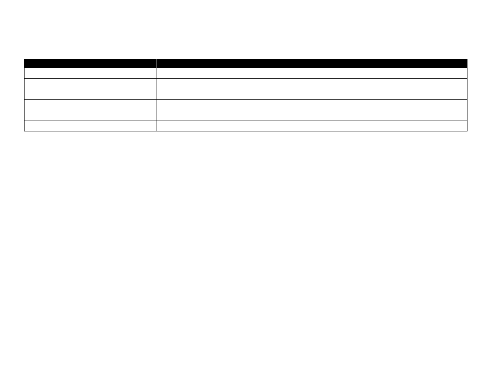
Revision Status
Revision Date of Issue Description
A May 10, 2002 First release
Page 6

EPSON Stylus Pro 7600/9600 Revision A
Contents
Chapter 1 Product Description
1.1 Product Description ............................................................................................ 12
1.1.1 Features ...................................................................................................... 12
1.1.2 Differences between Stylus Pro 7600 and Stylus Pro 9600 ...................... 13
1.2 Basic Specifications ............................................................................................ 14
1.2.1 Print Specifications .................................................................................... 14
1.2.2 Character Specification .............................................................................. 14
1.2.3 Control Code .............................................................................................. 14
1.2.4 Paper Feed ................................................................................................. 14
1.2.5 Paper Specifications ................................................................................... 15
1.2.5.1 Roll Paper ........................................................................................... 15
1.2.5.2 Sheet ................................................................................................... 16
1.2.5.3 Special Paper ...................................................................................... 18
1.2.6 Mechanism Specifications ......................................................................... 21
1.2.6.1 Printable Area ..................................................................................... 21
1.2.6.2 Paper Set Lever .................................................................................. 22
1.2.6.3 Cutting Specification .......................................................................... 22
1.2.6.4 Acoustic Noise ................................................................................... 23
1.2.7 Electrical Specifications (TBD) ................................................................. 23
1.2.8 Reliability .................................................................................................. 23
1.2.8.1 Total Print Volume ............................................................................. 23
1.2.8.2 Print Head Life ................................................................................... 23
1.2.8.3 Maintenance Tank Life ...................................................................... 23
1.2.8.4 Cutter Life average ............................................................................. 23
1.2.8.5 Maintenance Parts (TBD) ................................................................... 23
1.2.9 Ambient Conditions ................................................................................... 24
1.2.9.1 Temperature/Humidity ....................................................................... 24
1.2.9.2 Vibration ............................................................................................. 24
1.2.9.3 Shock .................................................................................................. 24
1.2.9.4 Surrounding Space ............................................................................. 25
1.2.10 Overall Dimensions ................................................................................. 26
1.2.11 Accessories .............................................................................................. 28
1.2.11.1 Accessories and Options for Stylus Pro 7600 .................................. 28
1.2.11.2 Accessories and Options for Stylus Pro 9600 .................................. 29
1.3 External View and Parts Names ......................................................................... 30
1.4 Operating Panel .................................................................................................. 31
1.4.1 Buttons and Functions ............................................................................... 31
1.4.1.1 Functions of Buttons .......................................................................... 31
1.4.1.2 LEDs ................................................................................................... 32
1.4.2 Indications on the Panel ............................................................................. 33
1.4.2.1 lED Indications in Normal Mode ....................................................... 33
1.4.2.2 LCD Indications in Normal Mode ..................................................... 34
1.4.3 SelecType .................................................................................................. 35
1.4.3.1 Outline ................................................................................................ 35
1.4.3.2 Panel Setting Menu Item .................................................................... 36
1.4.3.3 PG Setting .......................................................................................... 40
1.4.3.4 Page Lines .......................................................................................... 41
1.4.3.5 Interface Select ................................................................................... 41
1.4.3.6 Code Page Switching ......................................................................... 41
1.4.3.7 Roll Paper Margin .............................................................................. 41
1.4.3.8 Detect Paper Width ............................................................................ 42
1.4.3.9 Detect Skew Error .............................................................................. 42
1.4.3.10 Job Timeout Setting ......................................................................... 42
1.4.3.11 No margin print setting .................................................................... 43
1.4.3.12 Cutter position adjustment ............................................................... 44
1.4.3.13 Auto margin refresh ......................................................................... 44
1.4.3.14 Panel Setup Value Initialization ....................................................... 45
1.4.3.15 Nozzle Check Pattern Printing ......................................................... 45
1.4.3.16 Status Printing .................................................................................. 46
1.4.3.17 Job Information Print ....................................................................... 48
1.4.3.18 Firmware version .............................................................................. 49
1.4.3.19 Printable pages of each ink cartridge ............................................... 49
1.4.3.20 Ink remaining ................................................................................... 49
1.4.3.21 Maintenance tank count ................................................................... 49
1.4.3.22 Use counter ....................................................................................... 50
1.4.3.23 Clear use counter .............................................................................. 50
1.4.3.24 Job history display ............................................................................ 50
6
Page 7

EPSON Stylus Pro 7600/9600 Revision A
1.4.3.25 Job history clear ................................................................................ 50
1.4.3.26 Total prints ....................................................................................... 50
1.4.3.27 Consumables life .............................................................................. 51
1.4.3.28 Suction adjustment for paper setting and indicator display ............. 53
1.4.3.29 Ink remaining indicator display ........................................................ 54
1.4.3.30 Job information ................................................................................. 55
1.4.3.31 User Paper Setting ............................................................................ 56
1.4.3.32 Power cleaning ................................................................................. 60
1.4.3.33 Cutter Blade Replacement ................................................................ 60
1.4.3.34 Gap Adjustment (Bi-D Adjustment, Uni-D Adjustment) ................ 60
1.4.3.35 BK ink cartridge replacement ........................................................... 64
1.4.4 Maintenance Mode 1 ................................................................................. 66
1.4.5 Maintenance Mode 2 ................................................................................. 70
1.4.6 Paper feeding adjustment conversion table ............................................... 84
1.4.7 Firmware Reload ....................................................................................... 85
1.4.7.1 Reload from ROM-DIMM ................................................................. 85
1.4.7.2 Reload with F/W DOWNLOAD mode .............................................. 85
1.4.7.3 Installation with service utility (F/W Update function) ..................... 85
1.4.7.4 Compulsory start F/W DOWNLOAD mode ...................................... 85
1.4.8 Function to prevent irregular printing ........................................................ 86
1.4.9 Initialization ............................................................................................... 86
1.4.9.1 Hardware initialization ....................................................................... 86
1.4.9.2 Software initialization ........................................................................ 86
1.4.9.3 Panel initialization .............................................................................. 86
1.4.10 Default Setup Values ............................................................................... 87
1.4.10.1 Initial Setting for Operation ............................................................. 87
1.4.10.2 Ink Type Setting ............................................................................... 87
1.4.10.3 MW Printing Adjustment / Setting Values and Printing Modes ...... 88
1.4.10.4 Printing Mode Combination Table ................................................... 89
1.5 Controller ............................................................................................................ 90
1.6 Interfaces ............................................................................................................ 91
1.6.1 Parallel Interface ........................................................................................ 91
1.6.1.1 Compatibility Mode ........................................................................... 91
1.6.1.2 Nibble Mode ....................................................................................... 93
1.6.1.3 ECP Mode .......................................................................................... 94
1.6.2 USB interface ............................................................................................. 95
1.6.3 Optional Interface ...................................................................................... 96
1.6.4 Supplements ............................................................................................... 97
1.7 Optional Units and Consumables ....................................................................... 98
1.7.1 Ink Cartridge .............................................................................................. 98
1.7.2 Cleaning cartridge ...................................................................................... 99
1.7.3 Draining cartridge ...................................................................................... 99
1.7.4 Maintenance Tank ..................................................................................... 99
Chapter 2 Operating Principles
2.1 Overview .......................................................................................................... 101
2.2 Print Mechanism Components ......................................................................... 102
2.2.1 Carriage (CR) Mechanism ....................................................................... 103
2.2.2 Paper Feed Assembly .............................................................................. 113
2.2.3 Cleaning Mechanism ............................................................................... 115
2.2.4 Ink Supply Mechanism ............................................................................ 117
2.2.5 Others ....................................................................................................... 118
2.3 Outline of Control Circuit Board ...................................................................... 119
2.4 Outline of Power Supply Circuit Board ........................................................... 120
Chapter 3 Troubleshooting
3.1 Outline .............................................................................................................. 122
3.1.1 Introduction ............................................................................................. 122
3.2 Error Display .................................................................................................... 123
3.2.1 Errors ....................................................................................................... 123
3.2.1.1 Error Indications on LCD ................................................................. 123
3.2.1.2 Warning Indications on LCD ........................................................... 124
3.2.1.3 Service Call (Fatal) Errors ................................................................ 125
3.2.2 Errors ....................................................................................................... 126
3.2.2.1 Paper End/End of roll ....................................................................... 126
3.2.2.2 Wrong paper source is selected on panel ......................................... 126
3.2.2.3 Paper set lever is released during operation ..................................... 126
3.2.2.4 Paper set lever is released ................................................................. 127
3.2.2.5 Paper Jam ......................................................................................... 127
3.2.2.6 Front Cover Open ............................................................................. 127
3.2.2.7 Type-B I/F error ............................................................................... 128
3.2.2.8 Paper cutting error ............................................................................ 128
3.2.2.9 Paper Not Straight ............................................................................ 128
3.2.2.10 Paper check error/Paper eject error (sheet) .................................... 129
3.2.2.11 Paper is too thick for cleaning ........................................................ 129
3.2.2.12 Not enough ink for cleaning ........................................................... 129
7
Page 8

EPSON Stylus Pro 7600/9600 Revision A
3.2.2.13 Ink-related Errors ........................................................................... 130
3.2.2.14 Defective ink cartridge ................................................................... 130
3.2.2.15 Ink lever released ............................................................................ 130
3.2.2.16 Illegal ink cartridge ........................................................................ 131
3.2.2.17 Maintenance tank full ..................................................................... 131
3.2.2.18 No Maintenance tank ...................................................................... 131
3.2.2.19 Wrong IK designation .................................................................... 131
3.2.2.20 Fatal Error ....................................................................................... 131
3.2.3 Troubleshooting for Warning .................................................................. 132
3.2.3.1 Ink Low ............................................................................................ 132
3.2.3.2 Maintenance tank full warning ......................................................... 132
3.2.3.3 Maintenance request ......................................................................... 132
3.2.4 Troubleshooting for Service Call Errors .................................................. 134
3.2.4.1 CR motor life (00000101) ................................................................ 134
3.2.4.2 PF motor encoder check error (00010000) ....................................... 135
3.2.4.3 PF Motor out of step (00010001) ..................................................... 135
3.2.4.4 PF motor overcurrent (00010002) .................................................... 136
3.2.4.5 PF motor in-position time out (00010003) ....................................... 136
3.2.4.6 CR motor encoder check error (00010004) ...................................... 137
3.2.4.7 CR motor out of step (00010005) ..................................................... 137
3.2.4.8 CR motor overcurrent (00010006) ................................................... 138
3.2.4.9 CR motor in-position time-out (00010007) ...................................... 138
3.2.4.10 Servo interrupt watchdog time-out (00010008) ............................. 139
3.2.4.11 System interrupt watchdog time-out (00010009) ........................... 139
3.2.4.12 CR home position sensor error (0001000A) .................................. 139
3.2.4.13 PF home position sensor error (0001000B) ................................... 139
3.2.4.14 Head slide (PG) home position sensor error (0001000C) .............. 140
3.2.4.15 CR motor PWM output faulty (0001000F) .................................... 140
3.2.4.16 PF motor PWM output faulty (00010010) ..................................... 141
3.2.4.17 Head driver (TG) temperature error (0001001B) ........................... 141
3.2.4.18 CR servo parameter error (0001001D) ........................................... 142
3.2.4.19 PF servo parameter error (0001001E) ............................................ 142
3.2.4.20 CSIC reed/right error (00010020) .................................................. 143
3.2.4.21 Ink type error (setting on printer body side) (00010022) ............... 143
3.2.4.22 RTC analysis error (00010023) ...................................................... 143
3.2.4.23 CSIC ROM communication error (00010025) ............................... 144
3.2.4.24 RTC communication error (00010026) .......................................... 144
3.2.4.25 Head error (00010028) ................................................................... 144
3.2.4.26 Unidentified NMI (00010029) ....................................................... 144
3.2.4.27 CR ASIC ECU error (0001002A) .................................................. 144
3.2.4.28 PF ASIC ECU error (0001002B) ................................................... 144
3.2.4.29 NVRAM error (00020000) ............................................................. 144
3.2.4.30 SDRAM error (00020002) ............................................................. 145
3.2.4.31 BOOT program SUM error (00020003) ........................................ 145
3.2.4.32 Flash memory SUM error (00020009) ........................................... 145
3.2.4.33 Program load error (0002000A) ..................................................... 145
3.2.4.34 Internal memory shortage error (0002000B) ................................. 145
3.2.4.35 Review error (0002000C) ............................................................... 146
3.2.4.36 CPU address error (load misalignment) (100000E0) ................. 146
3.2.4.37 CPU address error (storage misalignment) (10000100) ................. 146
3.2.4.38 CPU reserve command code exception error (10000180) ............. 146
3.2.4.39 CPU slot illegal command exception error (100001A0) ................ 146
3.2.4.40 CPU DMA address error (100005C0) ............................................ 146
3.2.4.41 CPU error (10000xxx) .................................................................... 146
3.3 Troubleshooting Based on Your Printout ......................................................... 147
3.3.1 Dot Missing ............................................................................................. 147
3.3.2 Uneven Printing/Poor Resolution ............................................................ 148
3.3.3 Smudged or Marred Printout (Front) ....................................................... 148
3.3.4 Smudged or Marred Printout (Reverse side) ........................................... 149
3.3.5 White or Black Banding in the carriage running direction ...................... 149
3.3.6 Banding in the paper feed direction ......................................................... 150
Chapter 4 Disassembly & Assembly
4.1 Summary .......................................................................................................... 152
4.1.1 Precautions ............................................................................................... 152
4.1.2 Tools ........................................................................................................ 155
4.1.3 Screw List ................................................................................................ 155
4.1.4 Disassembly Flow .................................................................................... 156
4.2 Removing the Panel Unit and Housing ............................................................ 158
4.2.1 Panel Unit ................................................................................................ 159
4.2.2 R Side Cover ............................................................................................ 160
4.2.3 L Side Cover ............................................................................................ 163
4.2.4 I/H Cover ................................................................................................. 164
4.2.5 H Top Cover ............................................................................................ 165
4.2.6 Rear Cover ............................................................................................... 166
4.2.7 Paper Guide L2 ........................................................................................ 168
4.2.8 Roll Paper Cover ..................................................................................... 169
4.2.9 Front Cover .............................................................................................. 170
8
Page 9

EPSON Stylus Pro 7600/9600 Revision A
4.3 Disassembly and Assembly of Carriage (CR) Mechanism .............................. 171
4.3.1 Print Head ................................................................................................ 171
4.3.2 Damper ASSY ......................................................................................... 173
4.3.3 CR Board ASSY ...................................................................................... 174
4.3.4 Cutter Section .......................................................................................... 175
4.3.4.1 Cutter Holder ASSY ......................................................................... 175
4.3.4.2 Cutter Solenoid ................................................................................. 177
4.3.5 CR Encoder Sensor ASSY ....................................................................... 178
4.3.6 P_EGDE Sensor ASSY ........................................................................... 179
4.3.7 CR Motor ASSY ...................................................................................... 180
4.3.8 HEAD_SLIDE Sensor ASSY .................................................................. 182
4.3.9 CR_HP Sensor ASSY .............................................................................. 183
4.3.10 CR Encoder Scale (Timing Fence) ........................................................ 184
4.4 Disassembly and Assembly of Paper Feed Mechanism ................................... 185
4.4.1 PF Motor .................................................................................................. 185
4.4.2 PF Encoder Sensor ASSY ....................................................................... 186
4.4.3 Cautions when replacing the PF Loop Scale ........................................... 187
4.4.3.1 Assembly Procedure for the PF Loop Scale ASSY ......................... 187
4.4.3.2 PF Loop Scale ASSY Affixing Procedure ....................................... 188
4.4.4 Suction Fans ............................................................................................. 189
4.4.5 P_THICK Sensor/P_THICK Sensor_0.3 ASSY ..................................... 190
4.4.6 P_REAR Sensor ASSY ........................................................................... 191
4.5 Disassembly and Assembly of Ink Supply Mechanism ................................... 192
4.5.1 C472_SUB-B Board ................................................................................ 192
4.5.2 I/H (Ink Holder) ASSY ............................................................................ 193
4.5.3 Cover Sensor ASSY ................................................................................ 197
4.6 Disassembly and Assembly of Cleaning Mechanism ...................................... 198
4.6.1 Maintenance ASSY Removal .................................................................. 199
4.6.2 Pump Motor ASSY .................................................................................. 200
4.6.3 Cap ASSY ................................................................................................ 200
4.6.4 Pump ASSY ............................................................................................. 201
4.6.5 Cleaner Head (Wiper) .............................................................................. 203
4.6.6 Flushing Box ASSY ................................................................................ 204
4.7 Disassembly and Assembly of Circuit Boards ................................................. 205
4.7.1 Power Supply Board ................................................................................ 205
4.7.2 AC Inlet ................................................................................................... 206
4.7.3 MAIN Board (C472 MAIN) .................................................................... 207
4.7.4 DIP Switch and Jumper Setting at Factory before Shipment .................. 209
Chapter 5 Adjustment
5.1 Overview .......................................................................................................... 211
5.1.1 Cautions ................................................................................................... 211
5.1.2 Adjustment Tools .................................................................................... 211
5.1.3 Procedure for Adjustment Work .............................................................. 212
5.1.4 Adjustment Items ..................................................................................... 212
5.1.4.1 Print Head Adjustment ..................................................................... 212
5.1.4.2 Main Board Adjustment ................................................................... 213
5.1.4.3 CR Motor Adjustment ...................................................................... 214
5.1.4.4 PF Motor Adjustment ....................................................................... 214
5.1.4.5 P_EDGE Sensor ASSY Adjustment ................................................ 215
5.1.4.6 P_REAR Sensor ASSY Adjustment ................................................ 215
5.1.4.7 P_THICK/ P_THICK_0.3 Sensor ASSY Adjustment ..................... 215
5.1.4.8 CR Encoder Sensor ASSY Adjustment ........................................... 215
5.1.4.9 Cover Sensor ASSY Adjustment ..................................................... 216
5.1.4.10 PF Encoder Sensor ASSY Adjustment .......................................... 216
5.1.4.11 Cutter Solenoid ASSY or Paper Guide L Adjustment ................... 217
5.1.4.12 Damper ASSY Adjustment ............................................................ 217
5.1.4.13 Release Sensor (I/H Lever) Adjustment ......................................... 217
5.1.4.14 Battery ............................................................................................ 217
5.1.5 Parameter Backup .................................................................................... 218
5.1.5.1 Parameter Backup Procedure ........................................................... 218
5.1.5.2 Work Procedure ................................................................................ 218
5.1.5.3 Others ............................................................................................... 218
5.1.6 Firmware Reinstallation .......................................................................... 219
5.1.6.1 Firmware Installation through ROM-DIMM ................................... 219
5.1.6.2 Firmware Installation through Interface ........................................... 219
5.2 Self-diagnostic Function ................................................................................... 220
5.2.1 Overview ................................................................................................. 220
5.2.1.1 How to Start Self-diagnostic Function ............................................. 220
5.2.1.2 Functions of Keys during Self-diagnosis ......................................... 220
5.2.1.3 Top Menu ......................................................................................... 221
5.2.2 Test .......................................................................................................... 222
5.2.2.1 Version ............................................................................................. 223
5.2.2.2 Control Panel .................................................................................... 223
5.2.2.3 Sensors ............................................................................................. 224
5.2.2.4 Encoder ............................................................................................. 225
5.2.2.5 Fan .................................................................................................... 225
5.2.2.6 Record .............................................................................................. 226
9
Page 10

EPSON Stylus Pro 7600/9600 Revision A
5.2.2.7 CSIC ................................................................................................. 227
5.2.2.8 Actuator ............................................................................................ 229
5.2.2.9 Actuator 2 ......................................................................................... 229
5.2.3 Adjustment ............................................................................................... 230
5.2.3.1 Rear AD Adjustment ........................................................................ 231
5.2.3.2 Edge AD Adjustment ....................................................................... 232
5.2.3.3 Input Rank ........................................................................................ 233
5.2.3.4 Write D/A Value .............................................................................. 236
5.2.3.5 Check Nozzle ................................................................................... 237
5.2.3.6 Check Skew ...................................................................................... 238
5.2.3.7 Feed Correction + T&B Adjustment ................................................ 239
5.2.3.8 Top & Bottom Adjustment ............................................................... 242
5.2.3.9 Rear Sensor Position ........................................................................ 243
5.2.3.10 Platen Position (Sponge Position) Adjustment .............................. 244
5.2.3.11 Platen Position Checking ................................................................ 245
5.2.3.12 Head Slant Checking ...................................................................... 246
5.2.3.13 Round Trip Print Position Adjustment (Bi-D Adjustment) ............ 248
5.2.3.14 Parameter Copying ......................................................................... 251
5.2.3.15 Bi-D2 Adjustment (PG=0.7mm) .................................................... 251
5.2.3.16 Bi-D3 Adjustment (PG=2.1mm) .................................................... 251
5.2.3.17 Round Trip Print Position (Bi-D Adjustment) Checking ............... 252
5.2.3.18 Head Gap Adjustment (Uni-D Adjustment) ................................... 253
5.2.3.19 Test Pattern Printing ....................................................................... 255
5.2.3.20 Clean Head ..................................................................................... 256
5.2.3.21 Counter Clear ................................................................................. 257
5.2.4 Cleaning ................................................................................................... 259
5.2.5 Print .......................................................................................................... 259
5.2.6 Parameter ................................................................................................. 260
5.2.6.1 Parameter Initialize ........................................................................... 261
5.3 Mechanism Adjustment .................................................................................... 263
5.3.1 Overview .................................................................................................. 263
5.3.2 CR Timing Belt Tension Adjustment ...................................................... 263
5.3.3 PF Timing Belt Tension Adjustment ....................................................... 264
5.3.4 P_THICK_0.3/P_THICK Sensor Mounting Plate Position Adjustment . 265
5.3.5 Cover Sensor ASSY Mounting Position Adjustment .............................. 267
5.3.6 CR Encoder Sensor Mounting Position Adjustment ............................... 268
5.3.7 Cutter Positioning Adjustment ................................................................ 269
5.3.7.1 Paper Cutting Position Check ........................................................... 271
5.3.8 PF Encoder Sensor Installation Position Adjustment .............................. 272
5.3.9 USB ID Writing ....................................................................................... 273
Chapter 6 Maintenance
6.1 Overview .......................................................................................................... 275
6.1.1 Periodic Maintenance Items and Product Life Information .................... 276
6.1.2 Important Maintenance Items During Service Operations ...................... 279
6.2 Lubrication and Glue ........................................................................................ 280
6.2.1 Lubricating the CR Guide Rail ................................................................ 280
Chapter 7 Appendix
7.1 Connectors ........................................................................................................ 282
7.2 Component Layout ........................................................................................... 285
7.3 Circuit Diagrams .............................................................................................. 286
7.4 Exploded Diagrams .......................................................................................... 292
7.5 ASP List (Parts List) ......................................................................................... 317
7.5.1 ASP List for Stylus Pro 7600 .................................................................. 317
7.5.2 ASP List for Stylus Pro 9600 .................................................................. 320
10
Page 11

PRODUCT DESCRIPTION
CHAPTER
1
Page 12
EPSON Stylus Pro 7600/9600 Revision A
1.1 Product Description
1.1.1 Features
Large Format
Stylus Pro 7600: Max. 24 inch paper width, A1+ size supported
Stylus Pro 9600: Max. 44 inch paper width, B0+ size supported
Pigment ink / Dye ink
Pigment ink:
Users can select following blackish ink combinations.
• Photo Black + Light Black
• Matte Black + Light Black
• Matte Black × 2
Dye ink:
2 black ink cartridges are installed.
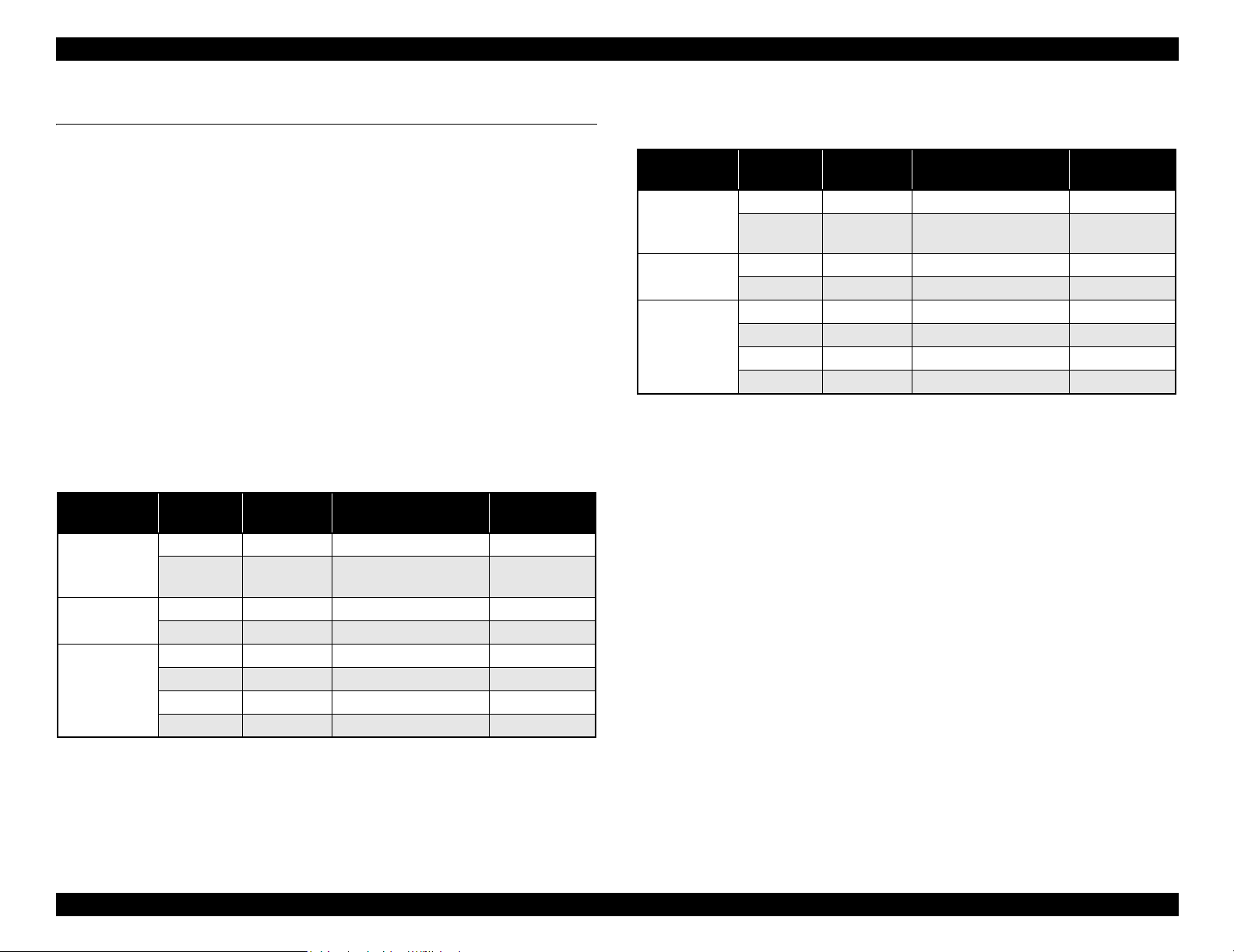
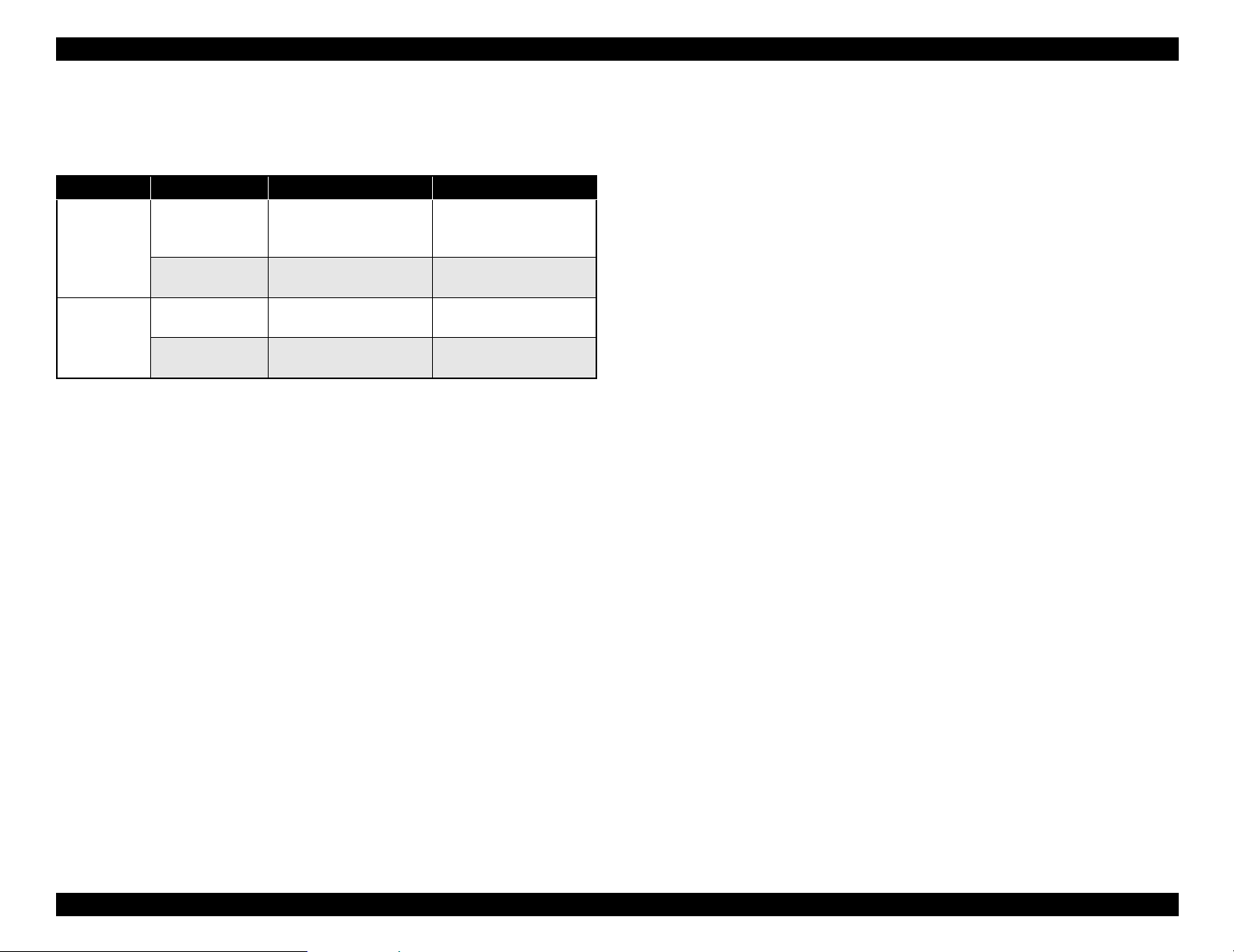
High-speed Throughput
Stylus Pro 7600
Table 1-1. Throughput (Stylus Pro 7600)
EPSON media Quality
Plain Paper Draft*
Doubleweight
Matte Paper
Glossy Photo
Paper
Glossy PaperHeavy Weight
1
Speed 360 × 360 Bi-D MF 240 cps 3/2 (BK×2*2)
Speed 360
Quality 720 × 360 Bi-DFOL(POL) 9 min
Speed 720
Quality 720 × 720 Bi-D 14POL 240 cps 13 min.
Adv.Photo 1440
Photo 2880 2880 × 1440 Bi-D 4-pass 190 cps 55 min
Resolution
(dpi)
360 × 180 Pseudo 4-color 2 min.
Mode
× 360 Bi-D M/W(POL) 240 cps 5 min.
× 360 Bi-D 22POL 240 cps 8 min.
× 720 Bi-D 4-pass 240 cps 25 min
Throughput
(A1 printing time)
min.
Stylus Pro 9600
Table 1-2. Throughput (Stylus Pro 9600)
EPSON media Quality
Plain Paper Draft*
Doubleweight
Matte Paper
Glossy Photo
Paper
Glossy PaperHeavy Weight
Note *1: Color high-speed 360×180dpi mode (for POP, for all ink combinations of pigment/
dye)
*2: Black double-speed mode (for CAD, supported with FW),
(It is switched automatically with 2 BK ink cartridge installation (dye/PPI) + M/W
OFF)
1
Speed 360 × 360 Bi-D MF 240 cps 6/3.5 (BK×2*2)
Speed 360
Quality 720 × 360 Bi-DFOL(POL) 17 min
Speed 720
Quality 720 × 720 Bi-D 14POL 240 cps 24 min
Adv.Photo 1440
Photo 2880 2880 × 1440 Bi-D 4-pass 190 cps 102 min
Resolution
(dpi)
360 × 180 Pseudo 4-color 3.5 min
Mode
× 360 Bi-D M/W(POL) 240 cps 9 min.
× 360 Bi-D 22POL 240 cps 14 min
× 720 Bi-D 4-pass 240 cps 46 min
Throughput
(A1 printing time)
min.
Super High Quality
High image quality with 7-color ink, 2880
layers.
×1440 dpi, and minimum 4pl various
Low Running Cost
• Independent for each color and 110 ml ink cartridge
• Large capacity 220 ml ink cartridge as an option
Paper Handling
• Support various media.
• Automatic roll paper cutter, manual cutter
• Automatic loading (cut sheet)
• Borderless print for right and left
Note *1 : Color high-speed 360×180dpi mode (for POP, for all ink combinations of pigment/
dye)
*2: Black double-speed mode (for CAD, supported with FW),
(It is switched automatically with 2 BK ink cartridge installation (dye/PPI) + M/W
OFF)
Compatibility with other LFPs
Commands are upper compatible with Stylus Pro 10000, Stylus Pro 10000CF,
Stylus Pro 9000, Stylus Pro 9500, Stylus Pro 7000, and Stylus Pro 7500.
The latest RIP technology
CPSI Pro software RIP
Product Description Product Description 12
Page 13
EPSON Stylus Pro 7600/9600 Revision A
1.1.2 Differences between Stylus Pro 7600 and Stylus Pro
9600
Table 1-3. Differences between Stylus Pro 7600 and Stylus Pro 9600
Item Stylus Pro 7600 Stylus Pro 9600
Product
Specifications
Option Take-up Reel Unit Not supported
Maximum paper
width
RAM capacity 32MB (16Mbit×2)
(IC600/601 = not mounted)
220 ml ink
cartridge
610mm
(About 24 inches /
A1+size supported)
(CN30 = not mounted)
Not supported Supported
1118m
(About 44 inches /
B0+size supported)
64MB (16Mbit×4)
Supported
Product Description Product Description 13
Page 14
EPSON Stylus Pro 7600/9600 Revision A
1.2 Basic Specifications
1.2.1 Print Specifications
Printing: On-demand ink-jet
Nozzle configuration:
Black: 192 nozzles (Black1, Black2, 96 nozzles each)
Color: 480 nozzles (cyan, magenta, light cyan, light magenta,
yellow, 96 nozzles each)
Nozzle pitch: 0.141mm (1/180 inch) for each color
Printing direction:
Bi-direction with logic seeking (high-speed return, high-speed skip only)
Printing speed and printable area
Character mode
• Character quality: high quality
• Character pitch: 10 cpi
• Printable area:
Stylus Pro 7600: 237 characters (at 10 cpi) / 8,561 dots (360dpi)
Stylus Pro 9600: 437 characters (at 10 cpi) / 15,840 dots (360dpi)
• Printing speed: 240 cps max.
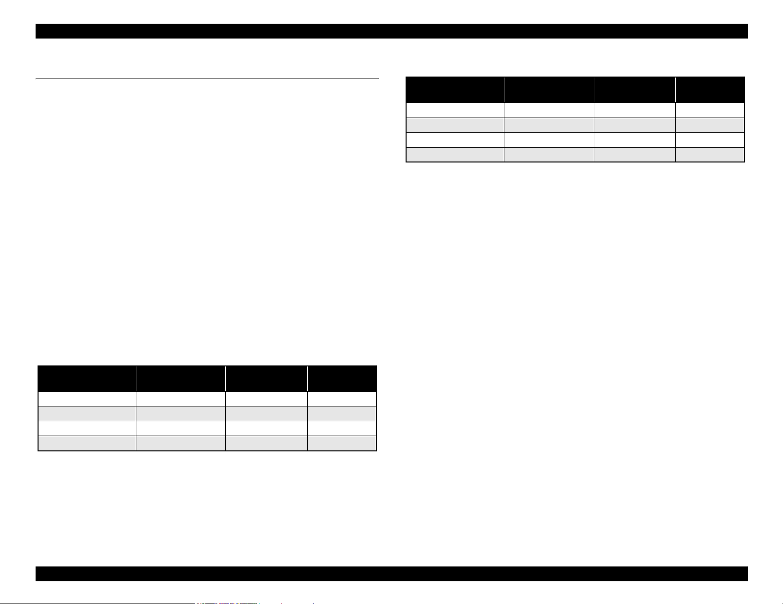
Graphic Mode
Table 1-4. Graphics Modes (Stylus Pro 7600)
Horizontal resolution
(dpi)
360 604 mm (24.16 inches) 8698 240 cps
720 604 mm (24.16 inches) 17395 240 cps
1440 604 mm (24.16 inches) 34790 240 cps
2880 604 mm (24.16 inches) 69581 190 cps
Printable area
Maximum number
of printable dots
Printing speed
Table 1-5. Graphics Modes (Stylus Pro 9600)
Horizontal resolution
(dpi)
360 1112 mm (43.78 inches) 15762 240 cps
720 1112 mm (43.78 inches) 31524 240 cps
1440 1112 mm (43.78 inches) 63048 240 cps
2880 1112 mm (43.78 inches) 126087 190 cps
Printable area
Maximum number
of printable dots
1.2.2 Character Specification
Character tables: 2 international character sets
PC 437 (US, Standard Europe)
PC 850 (Multilingual)
NOTE:
This specification is not described in the user's manual.
Typeface:
Bit map LQ font: EPSON Courier 10 cpi
NOTE:
This specifications is not described in the user's manual.
1.2.3 Control Code
Control code:
ESC/P Raster
ESC/P3
NOTE:
This specifications is not described in the user's manual.
1.2.4 Paper Feed
Paper feeding: Friction feed
Line spacing: 1/6 inch or programmable at 1440 inch
Paper path: Roll paper/manual
Feed speed: 6.35 mm paper feed: 215 ± 10 msec
(except front rush, back rush, and hold time)
Printing speed
Product Description Basic Specifications 14
Page 15
EPSON Stylus Pro 7600/9600 Revision A
1.2.5 Paper Specifications
1.2.5.1 Roll Paper
ACCEPTABLE PAPER
The printer accepts following plain paper and EPSON special paper. With any other
paper, proper paper feeding and satisfactory print quality are not ensured.
Paper Size
Table 1-6. Acceptable Roll Paper Sizes (Acceptable Paper)
Core Model Paper Size
2-inch core Stylus Pro 7600 203mm ~ 610 mm (W)
Stylus Pro 9600 203 mm ~ 1118 mm (W) × ~ 45 m (H) *
3-inch core Stylus Pro 7600 203 mm ~ 610 mm (W)
Stylus Pro 9600 203 mm ~ 1118 mm (W) × ~ 202 m (H) *
Note "* " : Within roll size
Roll Size
2-inch core: 103 mm ext. diameter maximum for 1 roll setting
3-inch core: 150 mm ext. diameter maximum for 1 roll setting
Thickness: 0.08 mm ~ 0.50 mm
× ~ 45 m (H) *
× ~ 202 m (H) *
PLAIN PAPER
Trouble-free paper feeding is ensured only in the following specifications.
Paper Size
Table 1-7. Acceptable Roll Paper Sizes (Plain Paper)
Core Model Paper Size
2-inch core Stylus Pro 7600 203 mm ~ 610 mm (W)
Stylus Pro 9600 203 mm ~ 1118 mm (W) × ~ 45m (H) *
3-inch core Stylus Pro 7600 203 mm ~ 610 mm (W)
Stylus Pro 9600 203 mm ~ 1118 mm (W) × ~ 202m (H) *
Note "* " : Within roll size
× ~ 45m (H) *
× ~ 202m (H) *
Roll Size
2-inch core: 103 mm ext. diameter maximum for 1 roll setting
3-inch core: 150 mm ext. diameter maximum for 1 roll setting
Thickness: 0.08 ~ 0.11 mm
Weight: 64 ~ 90gf/m
2
Type: Plain paper, Recycle paper
Product Description Basic Specifications 15
Page 16
EPSON Stylus Pro 7600/9600 Revision A
BORDERLESS PRINT ROLL PAPER
Borderless print for right and left is enssured for roll paper with any of the paper widths
as specified in Figure 1-9 below.
NOTE: 300 mm, 400 mm, 500 mm and 600 mm are supported for Europe.
Paper width
Table 1-8.
Stylus Pro 7600
Stylus Pro 9600
Japan 8”
USA/Europe 8”
Note 1: Paper should have no wrinkles, tears, or folds and the surface should be smooth.
2: The force to remove the end of the roll paper from the core should be between 300 gf
and 2000 gf
3: If core is used, a product-exclusive option (roll paper spindle 3 inch) is necessary.
4: It is used under normal conditions. (temperature 15
5: Roll paper can be printed before paper comes out of the core.
(Reference: Remaining paper length is 30cm approx. when roll paper come out of the
core.)
6: The mechanism clips print data out of over-printable area for borderless printing.
210
10” - 12” 14” - 16” - 20” - 24” 36” 44”
mm
210
mm
10”
300
mm
12” 14”
400
mm
16”
500
mm
20”
600
24” 36” 44”
mm
°C ~ 25°C, humidity 40 ~ 60%RH)
1.2.5.2 Sheet
ACCEPTABLE PAPER
The printer accepts following plain paper and special paper. With any other paper,
proper paper feeding and satisfactory print quality are not ensured.
Paper Size (The sizes indicated in bold italic are only for Stylus Pro 9600.)
Table 1-9. Acceptable Sheet Sizes (Acceptable Paper)
Paper Size Size (W × H) Paper Size Size (W × H)
B0+* 1118 mm
B0 * 1030 mm × 1456 mm US E 34 × 44 in
B1 * 728 mm
B2 515 mm × 728 mm US C 17 × 22 in
B3 364 mm
B4 257 mm × 364 mm 44 × 36 in * 44 × 36 in
A0+ * 914 mm
A0 * 841 mm × 1189 mm Letter 8.5 × 11 in
A1+ 24
A1 594m × 841 mm 8 × 10 in 8 × 10 in
A2 420 mm
A3+ 329 mm × 483 mm 60 cm × 90 cm 60 cm × 90 cm
A3 297 mm
× 1580 mm A4 210 mm × 297 mm
× 1030 mm US D 22 × 34 in
× 515 mm US B 11 × 17 in
× 1292 mm 30 × 24 in 30 × 24 in
× 36 in B1 (wide) * 1030 × 728 mm
× 594 mm 30 cm × 45 cm 30 cm × 45 cm
× 420 mm
Note " * " : Only for Stylus Pro 9600
Thickness
0.08 ~ 1.5 mm (paper length: 279 mm ~ 728 mm)
0.08 ~ 0.5 mm (paper length: 728 mm ~ 1580 mm)
NOTE 1: Paper should have no wrinkles, tears, or folds and the surface should be
smooth.
2:
0.08 ~ 1.50 mm paper thickness is supported for long-edge insertion.
3:
The sizes indicated in bold italic are only for Stylus Pro 9600.
Product Description Basic Specifications 16
Page 17
EPSON Stylus Pro 7600/9600 Revision A
PLAIN PAPER
Proper feeding is ensured only in the following specifications.
Paper Size: Same as above list
Thickness: 0.08 ~ 0.11 mm
Weight: 64 ~ 90 gf/m
2
Type: Plain paper, Recycle paper
NOTE 1: Paper is fed short-edge first.
2:
Paper should have no wrinkles, tears, or folds and the surface should be
smooth.
3:
It is used under normal conditions (temperature 15
60%RH)
4:
300mm, 400mm, 500mm, 600mm are supported for Europe.
5:
Mechanism clips print data out of over-printable area for borderless print.
BORDERLESS PRINT WIDTH
Borderless print for right and left is assured with following paper width. *4
~
25°C, humidity 40
C H E C K
P O I N T
~
Description of units of measure
cpi: characters per inch
dpi: dots per inch
cps: characters printed per second (at 10 cpi)
1 cps = 2.54 mm/s
ips: travel in inches per second
1 ips = 25.4 mm/s
G: Gravity
General ambient conditions:
Temperature 15
°C ~ 25°C
Humidity 40% ~ 60%
Paper width
Table 1-10.
Stylus Pro 7600
Stylus Pro 9600
210
Japan 8”
USA/Europe 8”
Product Description Basic Specifications 17
10” - 12” 14” - 16” - 20” - 24” 36” 44”
mm
210
mm
10”
300
mm
12” 14”
400
mm
16”
500
mm
20”
600
24” 36” 44”
mm
Page 18
EPSON Stylus Pro 7600/9600 Revision A
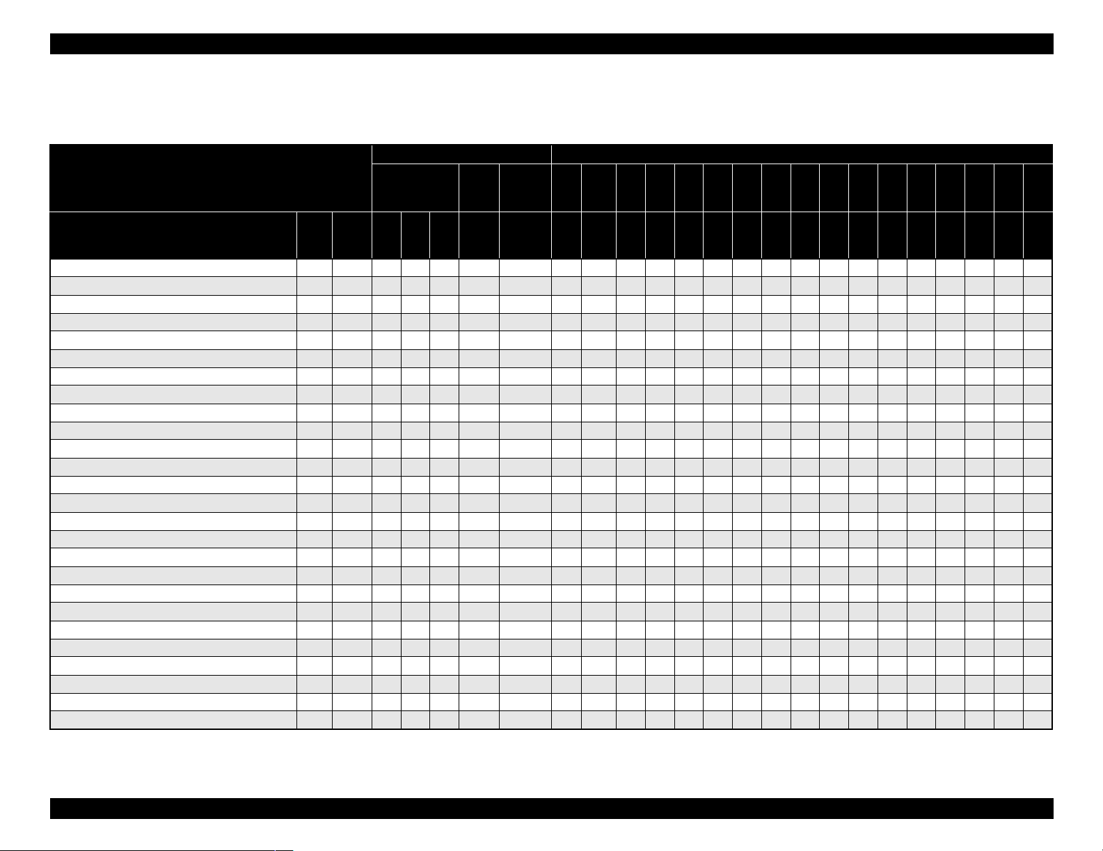
1.2.5.3 Special Paper
Roll (pigment)
Table 1-11. Availability with Special Paper (Pigment)
Characteristic Media Size
Roll / Pigment
Name Japan
Doubleweight Matte Paper
Glossy Paper - Photo Weight
Glossy Film
Premium Glossy Photo Paper
Premium Semigloss Photo Paper
Photo Glossy Paper / Photo Grade Glossy Paper
Photo Semigloss Paper / Photo Grade Semigloss Paper
Premium Glossy Photo Paper (250)
Premium Semigloss Photo Paper (250)
Premium Semimatte Photo Paper (250)
Premium Luster Photo Paper
Watercolor Paper - Radiant White
Smooth Fine Art Paper (Roll)
Textured Fine Art Paper (Roll)
Canvas
Backlight Film
Backlight Film (USA / Europe)
Heavyweight Polyester Banner
Enhanced Synthetic Paper
Adhesive Enhanced Synthetic Paper
Tyvek Brillion
Adhesive Vinyl
Enhanced Matte Paper
Semiglossy 2
Semiglossy 4
Dupont / EPSON Semi - Gloss Proofing Paper - A
Black INK
USA/
MK×2MK
Europe
/Asia
{{zz{20.21~ ------------~~~
{ { { 2 0.22 ~ - - - - - - - - - - ~ - - ~ ~
{{ {20.13~ ------------~~~
{ { { 2 0.18 ~ - - - - - - - - - - - - ~ ~ ~
{{ {20.18~ ------------~~~
{ { { 2 0.17 ~ - - - - - - - - - - - - ~ ~ ~
{{ {20.18~ ------------~~~
{ { { 3 0.26 ~ ~ - - - - - - - - - - - - ~ ~ ~
{{ {30.26~~ ------------~~~
{ { { 3 0.26 ~ ~ - - - - - - - - - - - - ~ ~ ~
{{ {30.26~~ --~~~~~ ~~ - ~~~~
{ { { { 3H 0.29 ~ - - - - - - - - - - - - ~ ~ ~
{{{3H 0.37 ------------~~~
{ { { { 3H 0.37 - - - - - - - - - - - - ~ ~ ~
{{{2 0.46 ------------~~~
{ { 2 0.13 ~ - - - - - - - - - - - - ~ ~ ~
{{2 0.18 ------------~~~
{ { z { 2 0.28 - - - - - - - - - - - - ~ ~ ~
{{zz{2H 0.12 ~ ------------~~~
{ { z z { 2H 0.17 ~ - - - - - - - - - - - - ~ ~ ~
{zz{ 20.24~ ------------~~~
{ z z { 2 0.33 - - - - - - - - - - - - ~ ~ ~
{{ {{30.25~ ------------~~~
TBD TBD { 2 TBD ~ - - - - - - - - - - - - ~ ~ -
{{2TBD~ ------------~~ -
{ { 2 0.20 - - - - - - - - - - - - ~ ~ -
+LKPK+LK
core”
spindle
Paper
thickness
(mm)
Auto
cut
Borde
rless
210
8”
mm
203 210 254 300 305 356 400 406 500 508 560 600 610 914 1118
10”
30
cm
12” 14”
40
cm
16”
50
cm
20” 22”
60
cm
24” 36” 44”
Note : Symbol ~: Assured, {: Supported, z: Supported conditionally, ×: Not supported, 2H/3H: High tension spindle
Product Description Basic Specifications 18
Page 19
EPSON Stylus Pro 7600/9600 Revision A
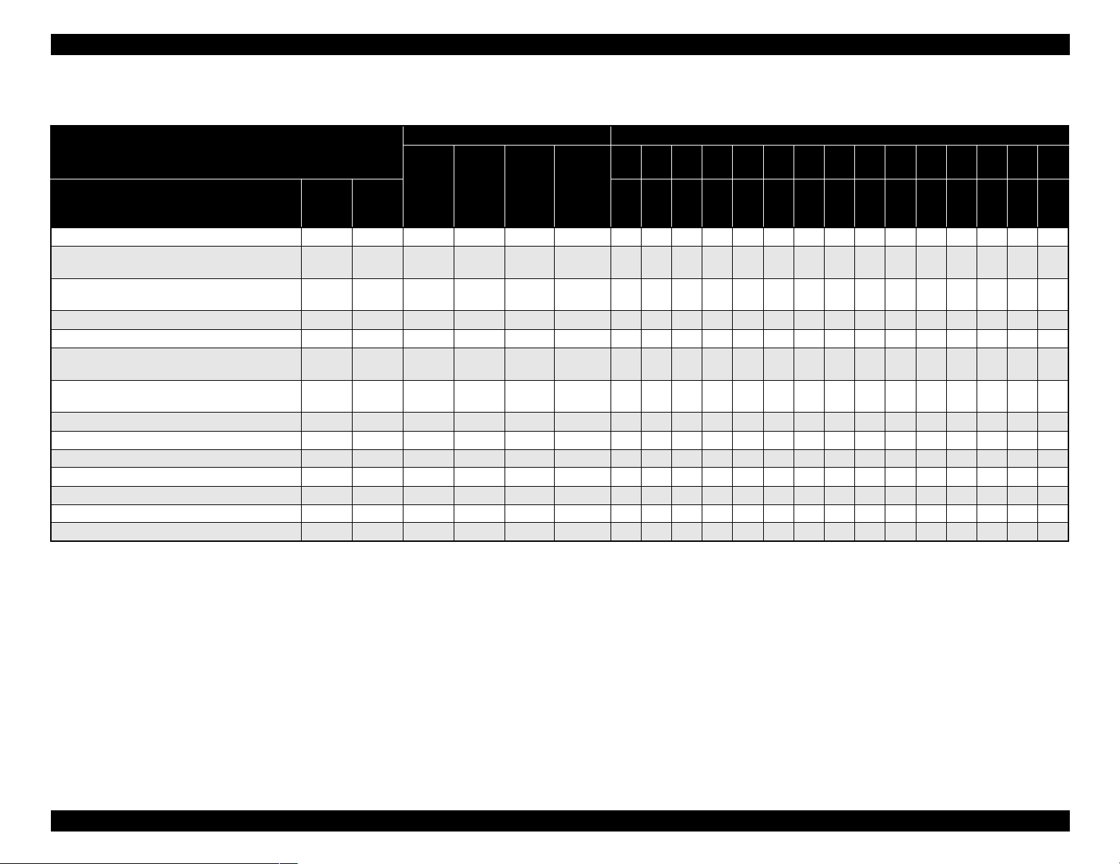
Roll (dye)
Table 1-12. Availability with Special Paper (Dye)
Characteristic Media Size
Roll / Dye
Name Japan
Presentation Matte Paper
Semigloss Photo Paper (Asia / Europe)
Semi Gloss Paper - Heavy Weight (US)
Glossy Photo Paper (Asia / Europe)
Glossy Paper - Heavy Weight (US)
Doubleweight Matte Paper
Glossy Film
Photo Grade Glossy Paper (Asia / Europe)
Photo Glossy Paper (US)
Photo Grade Semigloss Paper (Asia / Europe)
Photo Semigloss Paper (US)
Heavyweight Polyester Banner
RC 10mil Glossy Paper (TBD)
RC 10mil Semigloss Paper (TBD)
Premium Luster Photo Paper
Dupont / EPSON Commercial Proofing Paper
Dupont / EPSON Commercial Matte Proofing Paper
Dupont / EPSON Publication Proofing Paper
USA/
Europe/
Asia
{{ 20.20{ ------------~~~
{ { 2 0.21 { - - - - - - - - - - - - ~ ~ ~
{{ 20.23{ ------------~~~
{ 2 0.21 { - - - - - - - - - - - - ~ ~ ~
{{ 20.13{ ------------~~~
{ 2 0.17 { - - - - - - - - - - - - ~ ~ ~
{ 20.18{ ------------~~~
{ { 2 0.28 - - - - - - - - - - - - ~ ~ ~
TBD { 30.26{ ----------- ~~~
TBD { 3 0.26 { - - - - - - - - - - - - ~ ~ ~
TBD { 30.26{~--~~~~~~~~ - ~~~~
{ 2 0.21 { - - - - - - - - - - - - ~ ~ { 20.24{ ------------~~ { 2 0.24 { - - - - - - - - - - - - ~ ~ -
core”
spindle
Paper
thickness
(mm)
Auto cut Borderless
210
8”
203 210 254 300 305 356 400 406 500 508 560 600 610 914 1118
10” 30cm 12” 14” 40cm 16” 50cm 20” 22” 60cm 24” 36” 44”
mm
Note : Symbol ~: Assured, {: Supported, z: Supported conditionally, ×: Not supported, 2H/3H: High tension spindle
Note *1: Assured with Uni-D print.
*2: Paper is fed short-edge first.
*3: Paper should have no wrinkles, tears, or folds and the surface should be smooth.
*4: It is used under normal conditions (temperature 15°C ~ 25°C, humidity 40% ~ 60%RH)
*5: Paper feeding and print quality with borderless print is not assured on paper which is not assured for borderless print.
*6: Borderless print is not assured with sheet.
Product Description Basic Specifications 19
Page 20
EPSON Stylus Pro 7600/9600 Revision A
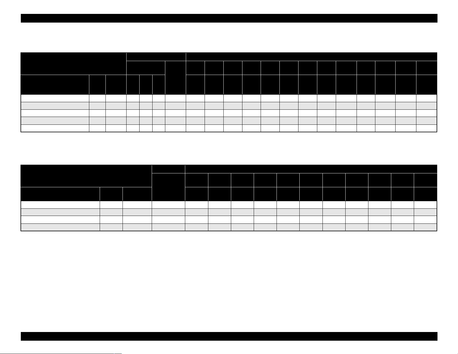
Sheet (pigment)
Table 1-13. Availability with Sheets (Pigment)
Characteristic Media size
Sheet / Pigment
Name Japan
Glossy Paper - Photo Weight
Watercolor Paper - Radiant White
Smooth Fine Art Paper
Textured Fine Art Paper
Enhanced Matte - Poster Board
USA/
Europe/
Asia
{{ { ~~~~~ ------- { { { { - - - - ~ - - - - - - - -
{{{0.67-------- - -~ - ~
TBD { { { 0.67 - - - - - - - - - - ~ - ~
{{ {{1.3 ------ - -~~ -
Black INK
MK×2MK
+LKPK+LK
Paper
thickness
(mm)
A4 LTR A3 B
210×297 216×279 297×420 279×432 329×483 420×594 432×559 515×728 728×1030 559×864 610×762 762×1016 914×1118
Note : Symbol ~: Assured, {: Supported, z: Supported conditionally, ×: Not supported, 2H/3H: High tension spindle
Super
A3/B
A2 C B2 A1 D 24”×30” 30”×40” 36”×44”
Sheet (dye)
Table 1-14. Availability with Sheets (Dye)
Characteri stic Mediasize
Sheet / Dye
Name Japan
Glossy Photo paper
Photo Quality Inkjet Paper
Glossy Film
Semigloss Paper - Poster Board
Paper
USA/Europe
/Asia
{ { ~~~~~ -----{ { ~ ~ ~ ~ ~ ~ ~ - - - { { ~~~~~ -----
{ - - - - - - - ~ - - ~
thickness
A4 LTR A3 B
210×297 216×279 297×420 279×432 329×483 420×594 432×559 515×728 728×1030 559×864 728×1030
Super
A3/B
A2 C B2 A1 D B1”
Note : Symbol ~: Assured, {: Supported, z: Supported conditionally, ×: Not supported, 2H/3H: High tension spindle
Note *1: Assured with Uni-D print.
*2: Paper is fed short-edge first.
*3: Paper should have no wrinkles, tears, or folds and the surface should be smooth.
*4: It is used under normal conditions (temperature 15°C~25°C, humidity
40%~60%RH)
Product Description Basic Specifications 20
Page 21
EPSON Stylus Pro 7600/9600 Revision A
1.2.6 Mechanism Specifications
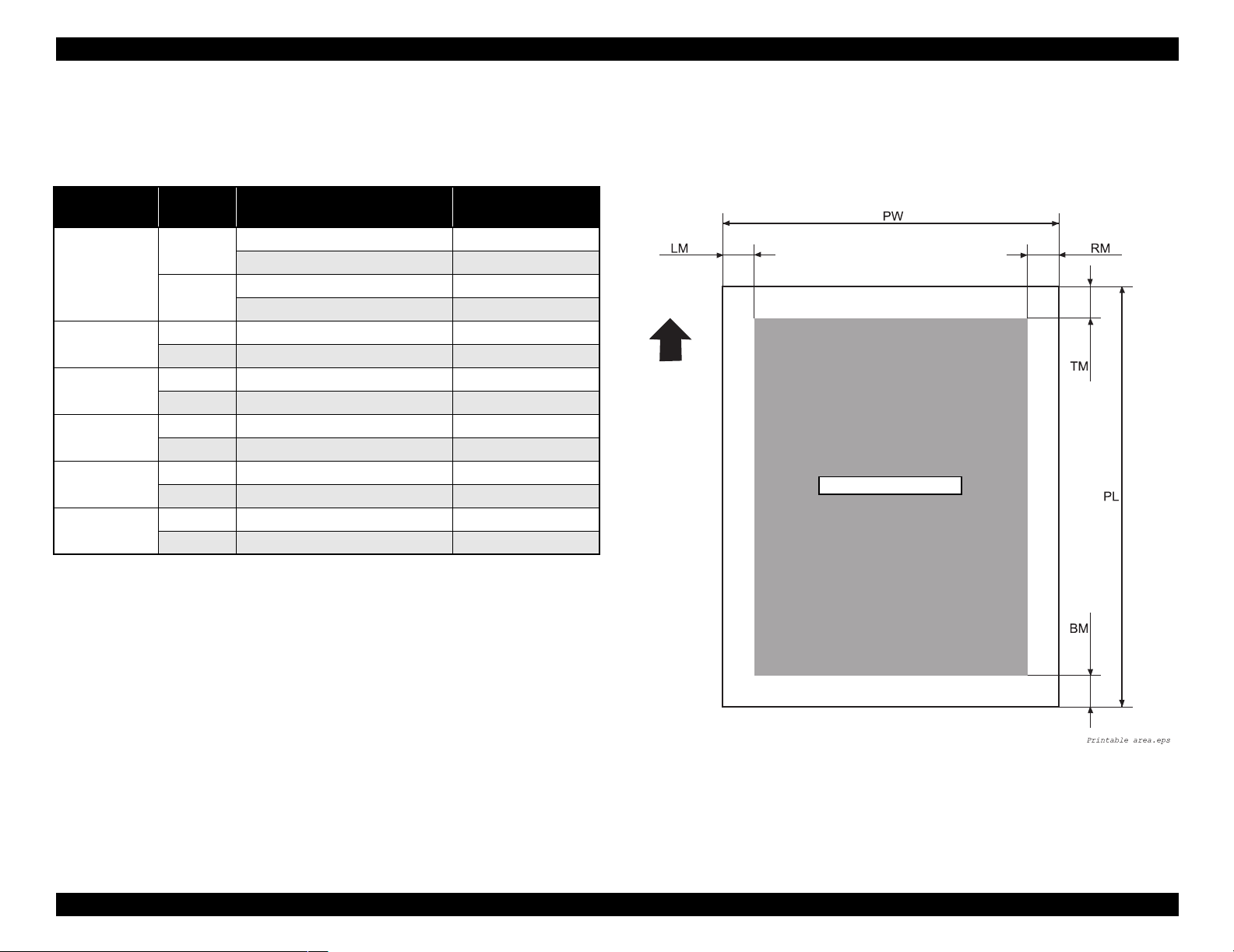
1.2.6.1 Printable Area
Table 1-15. Printable Area
Item
PW
(Paper width)
PL
(Paper length)
TM
(Top margin)
BM
(Bottom margin)
LM
(Left margin)
RM
(Right margin)
Roll paper
/Sheet
Roll paper Stylus Pro 7600 203 mm ~ 610 mm
Stylus Pro 9600 203 mm ~ 1118 mm
Sheet Stylus Pro 7600 203 mm ~ 610 mm
Stylus Pro 9600 203 mm ~ 1118 mm
Roll paper Stylus Pro 7600/Stylus Pro 9600 Max. 202m
Sheet Stylus Pro 7600/Stylus Pro 9600 279 mm ~ 1580 mm
Roll paper Stylus Pro 7600/Stylus Pro 9600 3 mm/15 mm
Sheet Stylus Pro 7600/Stylus Pro 9600 3 mm
Roll paper Stylus Pro 7600/Stylus Pro 9600 3 mm/15 mm
Sheet Stylus Pro 7600/Stylus Pro 9600 14 mm
Roll paper Stylus Pro 7600/Stylus Pro 9600 0 mm/3 mm/15 mm
Sheet Stylus Pro 7600/Stylus Pro 9600 0 mm/3 mm
Roll paper Stylus Pro 7600/Stylus Pro 9600 0 mm/3 mm/15 mm
Sheet Stylus Pro 7600/Stylus Pro 9600 0 mm/3 mm
Model Dimension
For borderless print, right and left margins are 3mm each because skew detection
limit is 3mm. If the distance from the paper edge to the platen (sponge width) is
less than 3mm, the maximum surplus print quantity without ink discharge onto the
platen (0mm~3mm) is printable area.
Paper Feed Direction
Printable Area
The printer detects paper width when paper is set. (If paper width detection setting
is OFF, it does not detect paper width.)
It does not print the image beyond the detected paper width or the printable area
specified by paper size setting.
(It may print on the platen if paper width detection setting is OFF.)
Margins of roll paper can be changed on the panel as follows;
Top/bottom 15 mm, left/right 3 mm
Top/bottom/left/right 3 mm
Top/bottom/left/right 15 mm
NOTE:
Under special conditions, it is possible to set right and left margin (LM,
RM) to 0.
Product Description Basic Specifications 21
Figure 1-1. Printable Area
Page 22
EPSON Stylus Pro 7600/9600 Revision A
1.2.6.2 Paper Set Lever
Table 1-16. Paper Set Lever
Lever Position Description
In the rear Position for paper setting
(You can set paper.)
In the front Ready-to-print position
(Paper is held with the paper holder.)
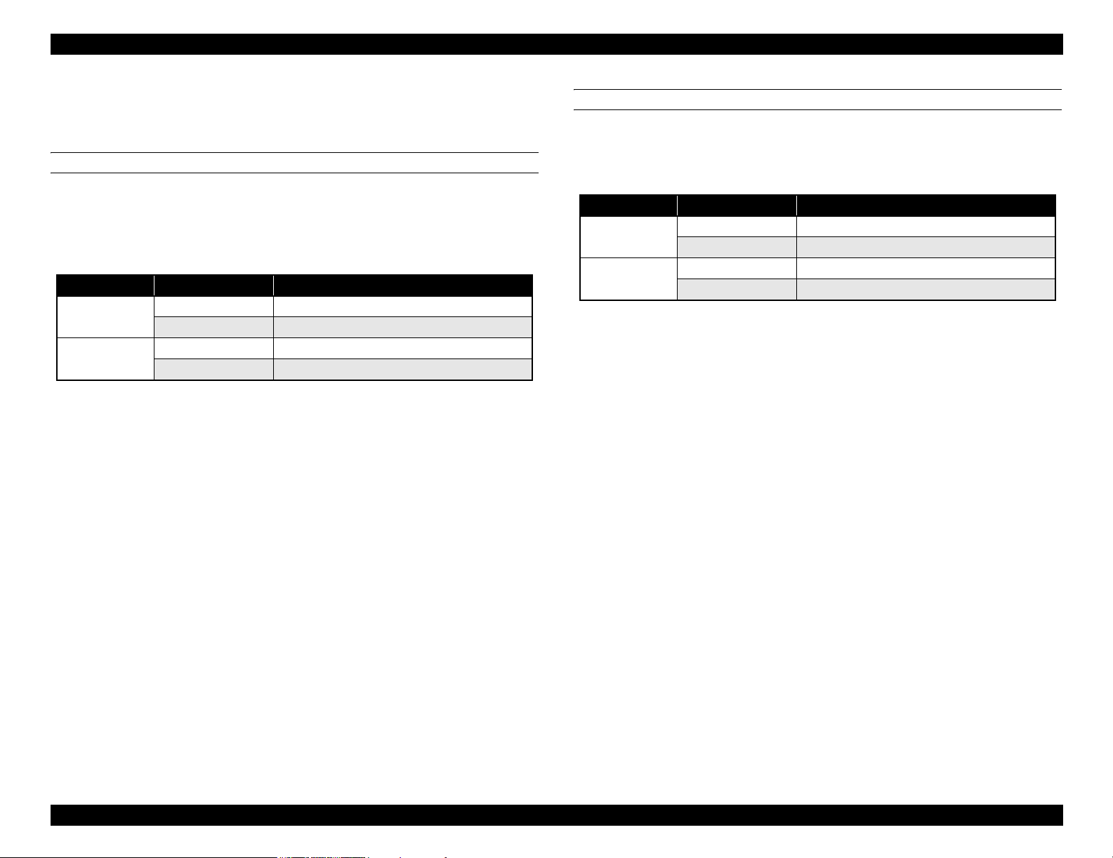
1.2.6.3 Cutting Specification
There are two methods to cut roll paper, automatic and manual cutting.
C A U T I O N
AUTOMATIC CUTTING OF ROLL MEDIA
Automatic cutting under the following conditions can only be performed on the
approved media.
Mechanical conditions
Distance between cut position and paper setting position: L0=167mm
Distance between cut position and cutter mark: L1= 44mm
Minimum cut length (same as paper edge waiting position): L2=030mm
Do not use the auto cutting function with any paper for which auto
cutting is prohibited; otherwise, the head would be damaged.
Table 1-17. Cutting Conditions and Cutting Methods
Cut condition Cut method
Initial cut (Cut with pushing “Cut/Eject” button after paper
is set, and set lever is pushed down.)
Cut after print completed by driver
Initial cut during printing
Initial cut during normal waiting status
Initial cut with Auto cut ON after print with Auto cut OFF.
Cut with Paper width detection OFF 3-step cut always (100cps fixed)
Note : Cutting pressure at high speed can be changed.
Cutting pressure at low speed is “Duty: 45%” fixed.
Paper edge waiting position is fed L2 for initial cut.
Paper is fed for L1 length and cut in 4 steps.
(50cps)
4-step cut (200cps) When paper is shorter
than L2, it is cut after feeding L2.
Cut during printing is not allowed with this
printer. (Product specification)
Paper is fed for L1 length and cut in 4 steps.
(50cps)
4-step cut (200cps), when paper is longer
than L2. 4-step cut (50cps) after feeding L2,
when paper is shorter than L2.
MANUAL CUTTING OF ROLL PAPER
Manual cutting is performed by the following procedure.
1. Select “Roll Cutter Off” on the panel.
2. Press “Cut/ Eject” button.
3. Paper is automatically fed toward the cutter guide, and printer becomes Off-line.
“Pause” is indicated on the LCD panel.
4. Adjust cutting position with “Paper Feed +/-” button if necessary.
5. Slide the cutter along the cutter guide to cut the paper.
6. After cutting, release the printer from the pause status by pressing the “Pause”
button. Then paper is fed backward and printer enters on-line.
C H E C K
P O I N T
For manual cutting of roll paper, use the manual cutter available as
an option.
Product Description Basic Specifications 22
Page 23
EPSON Stylus Pro 7600/9600 Revision A
1.2.6.4 Acoustic Noise
Level: Approx. 50dB(A) (According to ISO 7779)
1.2.7 Electrical Specifications (TBD)
Rated voltage: AC 100 ~ 240V
Input voltage range: AC 90 ~ 264V
Rated frequency range: 50 ~ 60Hz
Input frequency range: 49 ~ 61Hz
Rated current:
Stylus Pro 7600: 1.0A/100-120v, 0.5A/220-240v
Stylus Pro 9600: 1.0A/100-120v, 0.5A/220-240v
Power consumption:
Operation status: Stylus Pro 7600 50W
Stylus Pro 9600 55W
Waiting status: Less than 15W (shifting time: 15 minutes)
Power OFF: Less than 0.7W
Insulation resistance: More than 10M ohms
(between AC line and chassis, DC 500V)
Dielectric strength: AC 1.0kV rms 1min.
AC1.2kV rms 1 sec.
(between AC line and chassis)
1.2.8 Reliability
1.2.8.1 Total Print Volume
Stylus Pro 7600: 50,000 pages, 6.5million pass approx. (A1, 360×360 M/F, Bi-D)
Stylus Pro 9600: 20,000 pages, 5million pass approx. (B0, 360×360 M/F, Bi-D)
1.2.8.2 Print Head Life
Monochrome: 28billion shot / nozzle
Color: 28billion shot / nozzle
1.2.8.3 Maintenance Tank Life
Stylus Pro 7600: 11,000 pages approx.
(A1, plain paper, Speed mode, continuous print)
Stylus Pro 9600: 5,000 pages approx.
(B0, plain paper, Speed mode, continuous print)
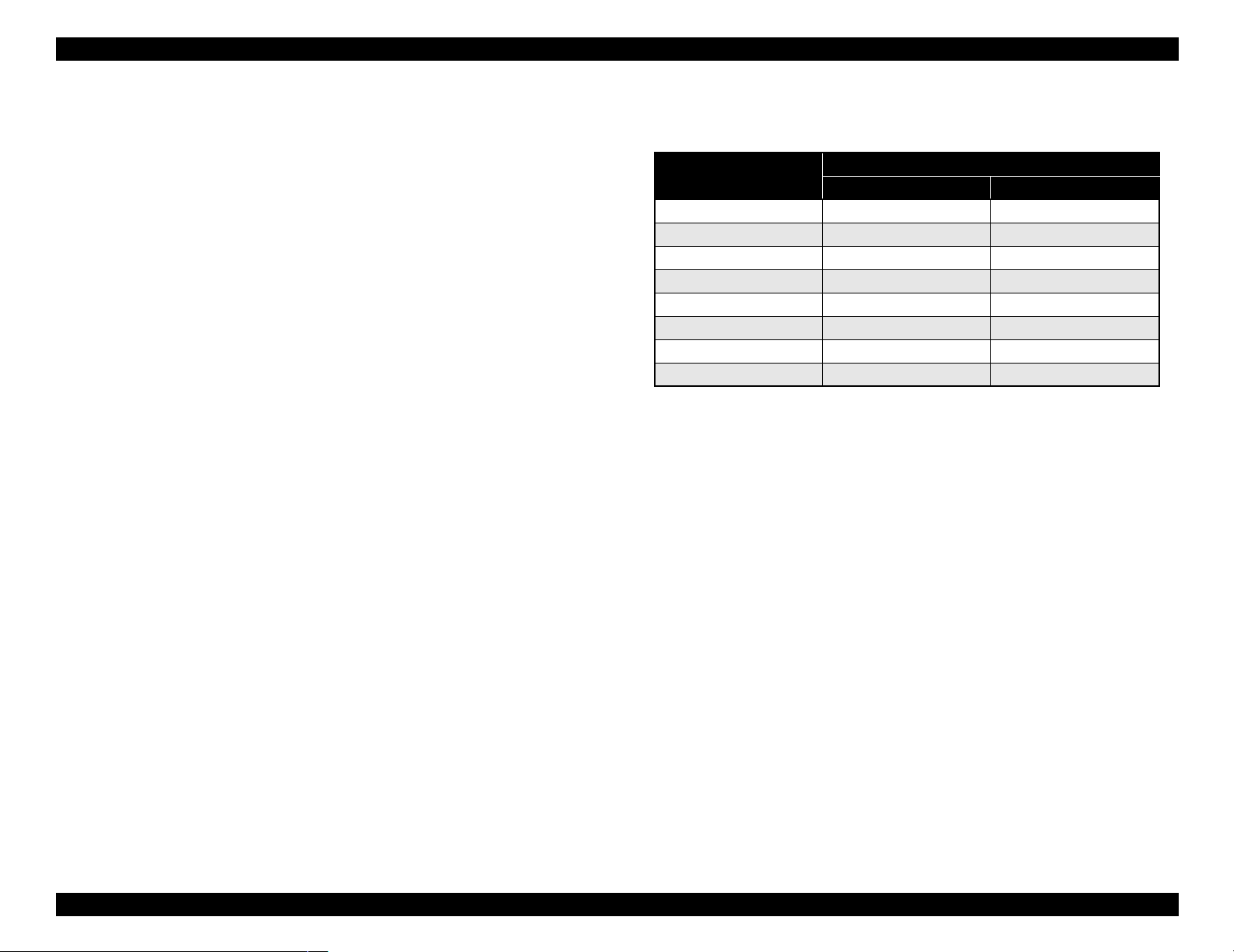
1.2.8.4 Cutter Life average
Table 1-18. Cutter life average
Stylus Pro 7600
Paper Type
Coated paper Approx. 2000 sheets Approx. 2000 sheets
Film Approx. 1000 sheets Approx. 1000 sheets
For 24-inch standard roll paper,
3-step cutting
For 44-inch standard roll paper,
Stylus Pro 9600
3-step cutting
Leakage: Less than 0.25mA
International Energy Star Program Compliant:
(Complies with the power supply harmonic control
guideline)
1.2.8.5 Maintenance Parts (TBD)
RTC backup battery: (TBD)
Cleaning unit life average
(Cap assembly, Pomp assembly, Flushing box, Wiper)
Stylus Pro 7600: 18,000 pages approx.
(A1, plain paper, Speed mode, continuous print)
Stylus Pro 9600: 8,000 pages approx.
(B0, plain paper, Speed mode, continuous print)
Ink absorbent sponge for right/left borderless print: (TBD)
Product Description Basic Specifications 23
Page 24
EPSON Stylus Pro 7600/9600 Revision A
1.2.9 Ambient Conditions
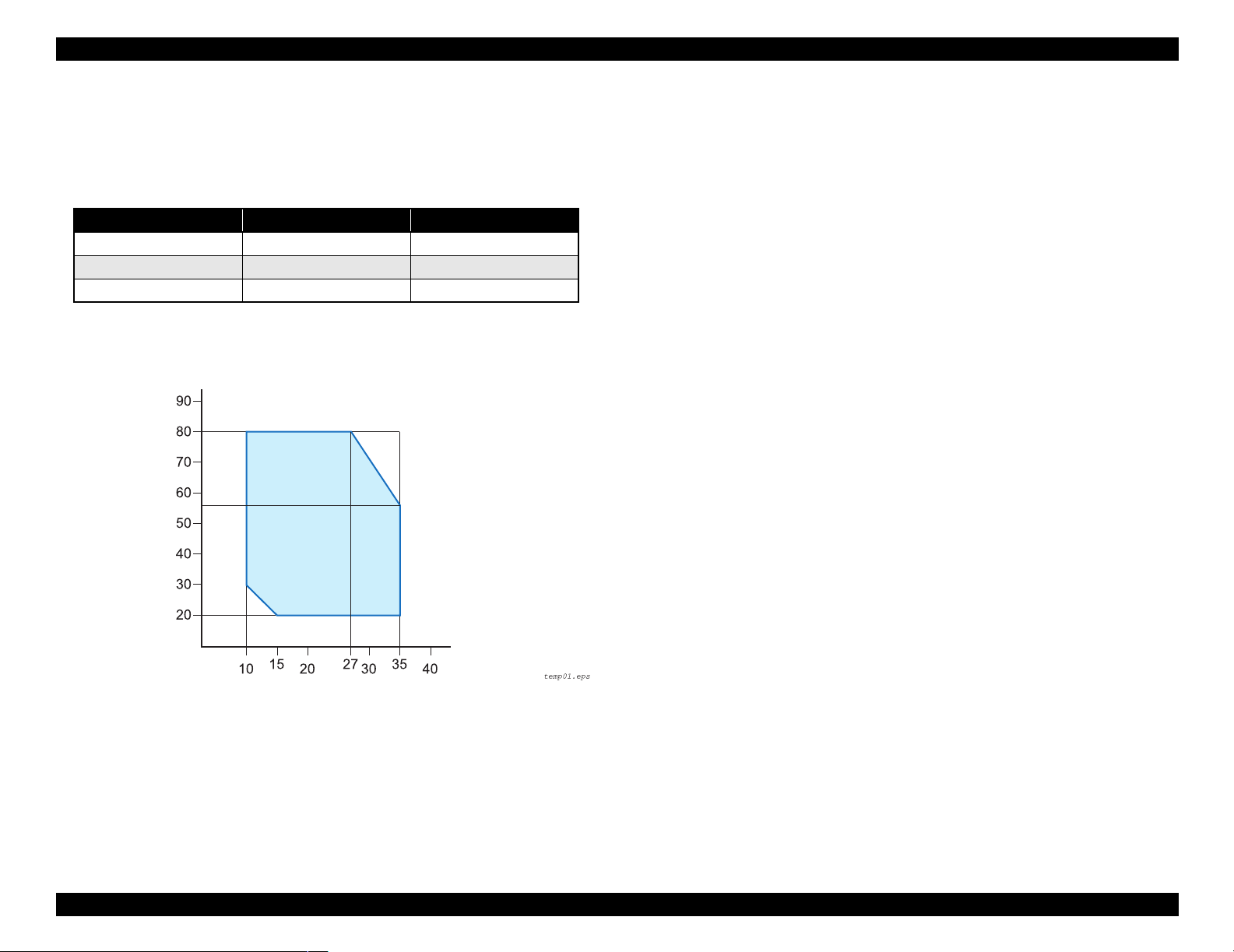
1.2.9.1 Temperature/Humidity
Table 1-19. Temperature/Humidity
Condition Temperature*
During operation 10 ~ 35°C 20 ~ 80%
During storage -20 ~ 40°C 20 ~ 85%
During transport -20
Note *1 : 120 hours max. at 60°C, one month max. at 40°C
*2: No condensation. These values are applicable only within the range as shown below.
Humidity (%)
~ 60°C 5 ~ 85%
1
Humidity*
1.2.9.3 Shock
During operation: 1G, 1ms max. X,Y and Z directions
During storage: 2G, 2ms max. X,Y and Z directions
NOTE 1: For storage, check that the print head is capped.
2
2:
Before transportation, check that the print head is capped, remove the ink
cartridges, and close the ink cartridge cover .
3:
If the power to the printer is OFF with the printer head uncapped, turn the
power ON with the ink cartridges installed. Then wait until capping is
completed, and turn the power OFF.
4:
If the printer is left standing at temperature of -15°C or below, the ink in the
print head and ink cartridges will freeze. If the ink is frozen, leave the printer
standing at temperature of 25°C for more than three hours before its use.
Temperature (°C)
Figure 1-2. Environmental Conditions: Temperature/Humidity
1.2.9.2 Vibration
During operation: 0.15G, 10 ~ 55Hz X,Y and Z directions
During storage: 0.50G, 10 ~ 55Hz X,Y and Z directions
Product Description Basic Specifications 24
Page 25
EPSON Stylus Pro 7600/9600 Revision A
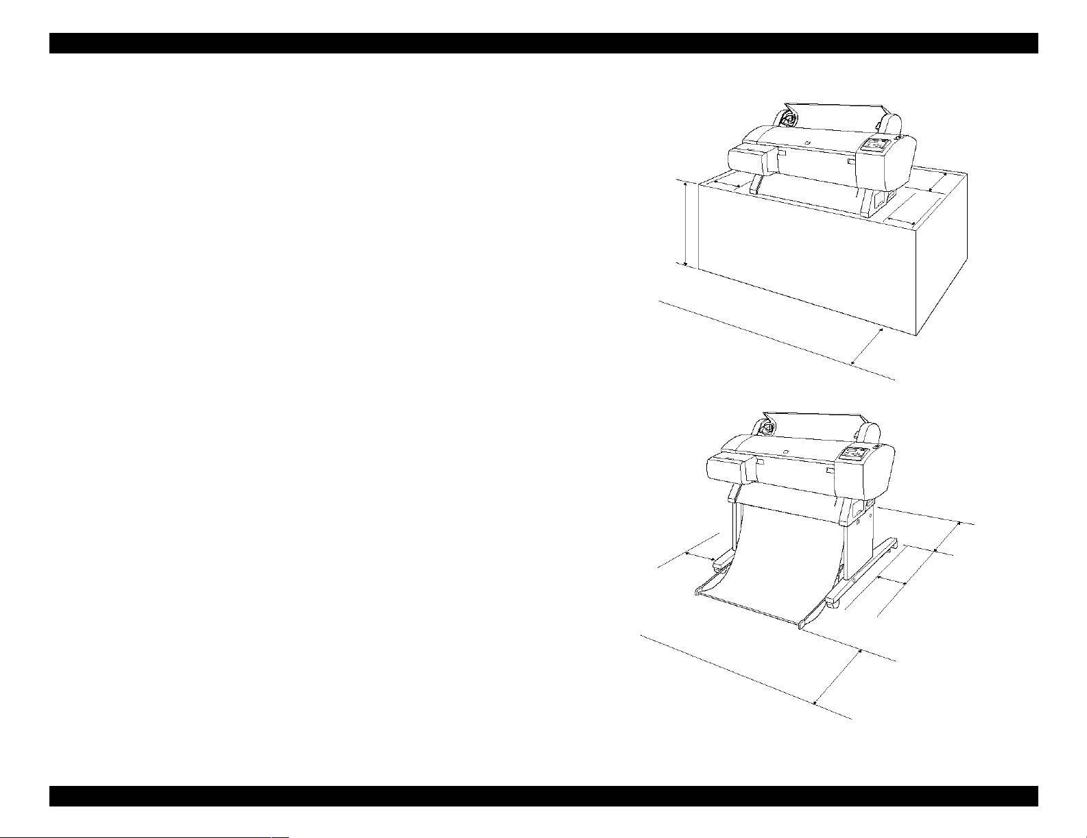
1.2.9.4 Surrounding Space
Provide the printer with an enough surrounding space to ensure proper installation of
accessories and replacement of consumables and easy work for daily maintenance.
From the front of the printer: 60 cm or more
From the rear and both sides of the printer: 15 cm or more
When Stylus Pro 7600 is not equipped with the dedicated stand:
Stylus Pro 7600 ejects paper downward. To prevent the ejected paper from
being obstructed, install the printer on a table or desk 60 to 80 cm high above
the floor and provide the printer with a 60 cm or more space in front.
In doing so, locate the front rubber feet of the printer close to the front end of
the table or the desk.
Stylus Pro 7600
(without stand)
15 cm or more
15 cm or more
60~80 cm or more
15 cm or more
60 cm or more
Stylus Pro 7600 (with stand)/
Stylus Pro 9600
15 cm or more
15 cm or more
60 cm or more
* Shown above is Stylus Pro 7600
15 cm or more
Figure 1-3. Surrounding Space
Product Description Basic Specifications 25
Page 26
EPSON Stylus Pro 7600/9600 Revision A
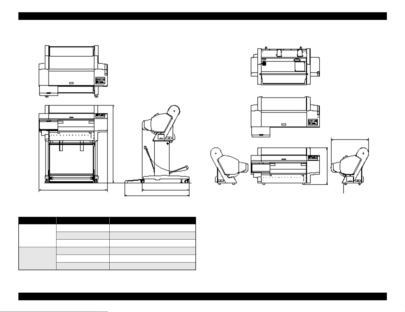
1.2.10 Overall Dimensions
604.94
1181.21
560.91
1100 754.11
1033.94
Figure 1-4. Overall Dimensions of Stylus Pro 7600
Dimensions of Unit
Model Condition Width (W) × Depth (D) × Height (H) (mm)
Stylus Pro 7600 Printer body 1100 ×805 × 561
Rearward paper eject 1100 × 754 × 1181
Frontward paper eject 1100
Stylus Pro 9600 Frontward paper eject 1624 × 691 × 1178
Rearward paper eject 1624
Frontward paper eject 1624 × 1076 × 1178
× 1034 × 1181
× 697 × 1178
Note 1: For “rearward paper eject”, the paper exit tray is brought down toward the rear.
2: For “frontward paper eject”, the paper exit tray is brought down toward the front.
Product Description Basic Specifications 26
Page 27
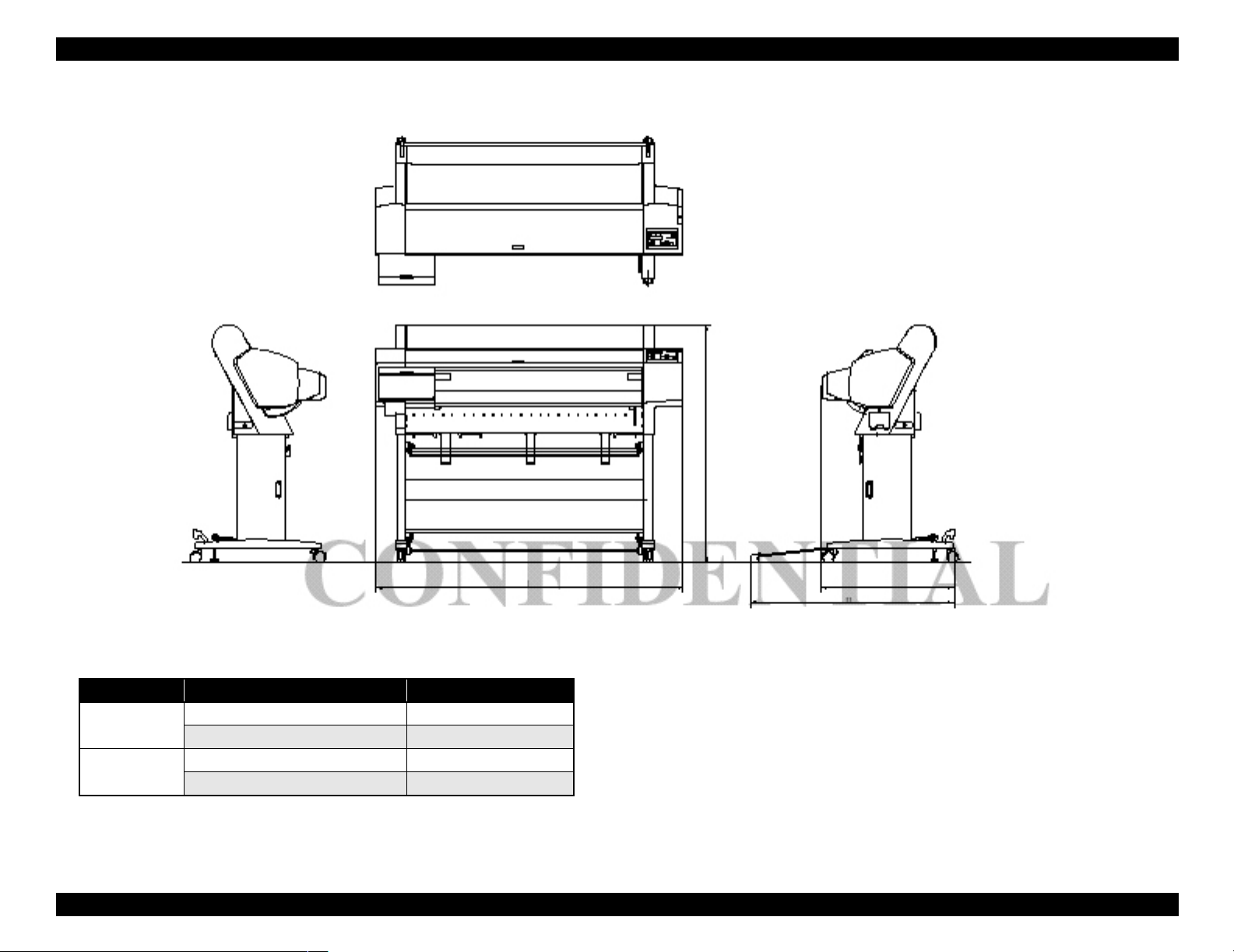
EPSON Stylus Pro 7600/9600 Revision A
1178.41
1624.1
697
1076.33
Figure 1-5. Overall Dimensions of Stylus Pro 9600
Weight
Model Condition Weight
Stylus Pro 7600 Printer body (without feet mounted) * About 43.5 kg
Feet About 10.5 kg
Stylus Pro 9600 Printer body (without feet mounted) * About 62.0 kg
Feet About 22.5 kg
Note "*": Excluding the ink cartridges
Product Description Basic Specifications 27
Page 28
EPSON Stylus Pro 7600/9600 Revision A
1.2.11 Accessories
This section describes the accessories and options for Stylus Pro 7600 and Stylus Pro
9600.
1.2.11.1 Accessories and Options for Stylus Pro 7600
Standard Accessories
AC Cable
Change Plug Adapter 3pin to 2pin
24 (2/3) inch roll paper spindle
Roll paper sample
Roll paper belt
Ink cartridges (110ml PK, MK, LK, C, M, LC, LM, Y)
Maintenance Tank
User's Manual
Driver & User's Manual
EPSON GrayBalancer & EPSON Printer Service Utility
Utility Software
Guarantee Card
Card holder
Carton Box
Special Options
Special stand (PX70MCU)
Manual cutter unit 24” (PX70MCU)
Normal tension spindle 24”<2”/3”> (PX70RPSD)
Black ink replacement kit (Draining cartridge, Cleaning cartridge)
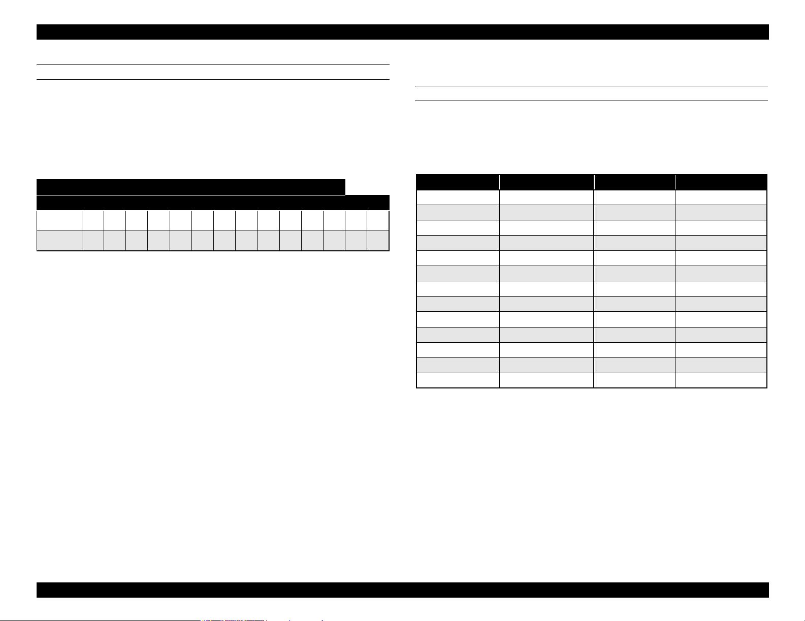
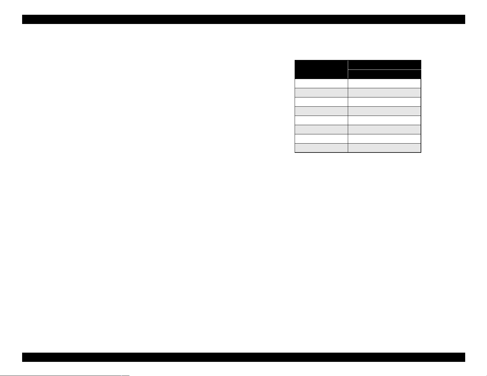
Special Consumables
Ink cartridge (110ml)
Name
Photo Black ICBK24
Matte Black ICMB24
Light Black ICGY24
Cyan ICC24
Magenta ICLC24
Light Cyan ICM24
Light Magenta ICLM24
Yellow ICY24
Note : The 220 ml ink cartridges are supported only by Stylus Pro 9600.
Model Number
110 ml (Standard Product)
Special paper (Refer to “1.2.5 Paper Specifications (p.15)” for paper type and
size)
Maintenance tank
Options Common to Other Printers
Auto cutter blade (PM90SPB)
Leo 2.13 (PRIFNW3S)
Fairbanks (PRIF14)
Product Description Basic Specifications 28
Page 29
EPSON Stylus Pro 7600/9600 Revision A
1.2.11.2 Accessories and Options for Stylus Pro 9600
Standard accessories
AC Cable
Change Plug Adapter 3pin to 2pin
Special stand
44 (2/3) inch roll paper spindle
Roll paper sample
Roll paper belt
Ink cartridges (110ml PK, MK, LK, C, M, LC, LM, Y)
Maintenance Tank
User's Manual
Driver & User's Manual
EPSON GrayBalancer & EPSON Printer Service Utility
Utility Software
Guarantee Card
Card holder
Carton Box
Special Options
Manual cutter unit 44”(PX90MCU)
Normal tension spindle 44”<2”/3”> (PX90RPSD)
High tension spindle 44”<2”/3”> (PX90HSD)
Black ink replacement kit (Draining cartridge, Cleaning cartridge)
Special Consumables
Ink cartridge (110 ml/220 ml (only for pigment))
Name
Photo Black ICBK24 ICBK25
Matte Black ICMB24 ICMB25
Light Black ICGY24 ICGY25
Cyan ICC24 ICC25
Magenta ICLC24 ICLC25
Light Cyan ICM24 ICM25
Light Magenta ICLM24 ICLM25
Yellow ICY24 ICY25
Note : The 220 ml ink cartridges are supported only by Stylus Pro 9600.
110 ml (Standard Product) 220ml (Option)
Model Number
Special paper (Refer to “1.2.5 Paper Specifications (p.15)” for paper type and
size)
Maintenance tank
Options common to other printers
Auto cutter blade (PM90SPB)
Take-up roller (PMARFU1)
Leo 2.13 (PRIFNW3S)
Fairbanks (PRIF14)
*
Product Description Basic Specifications 29
Page 30
EPSON Stylus Pro 7600/9600 Revision A
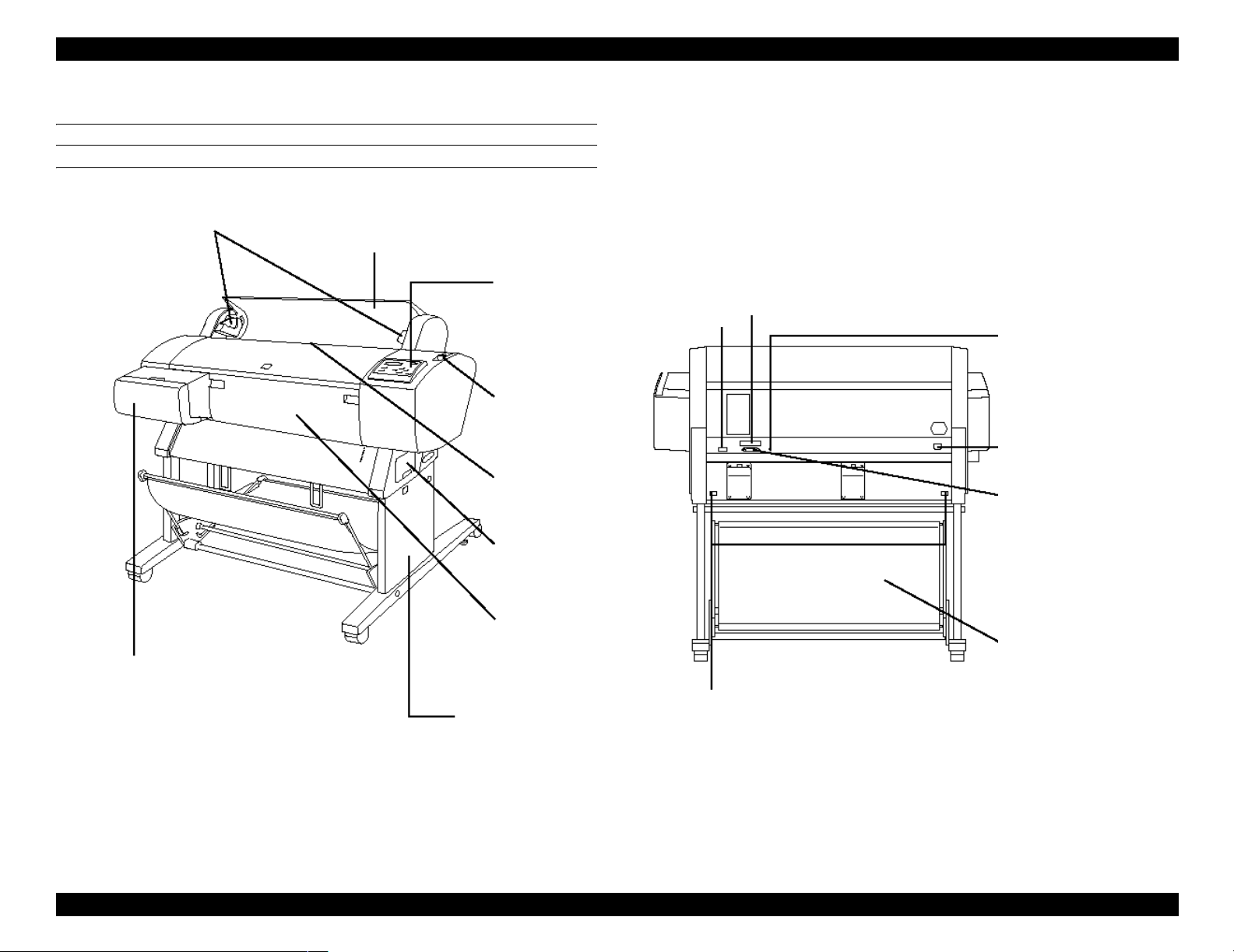
1.3 External View and Parts Names
EXTERNAL VIEW
Spindle Support
Paper Cover
Control Panel
Connector for Take-up Drive Unit
(Stylus Pro 9600 only)
Control Panel
Paper Set Lever
Connector Cover
USB Interface Connector
AC Inlet
Parallel Interface Connector
Paper Feed Slot
Maintenance Tank
Paper Receive Basket
Ink Cartridge Box
Clamp
Dedicated Stand
Stylus Pro 7600: Option
Stylus Pro 9600: Standard
Stylus Pro 7600: Option
Stylus Pro 9600: Standard
Note : Shown above is Stylus Pro 7600
Figure 1-6. External View and Parts Names
Product Description External View and Parts Names 30
Page 31

EPSON Stylus Pro 7600/9600 Revision A
1.4 Operating Panel
1.4.1 Buttons and Functions
The operating panel contains the following buttons.
Figure 1-7. Panel Design
Power
Pause
SelecType (Panel setting menu shift, setting item shift (down))
Paper Feed ∆ (setup value +)
Paper Feed ∇ (setup value -)
Paper Source (Item shift (up))
Cut / Eject (Enter)
Cleaning
1.4.1.1 Functions of Buttons
Table 1-20. Panel Functions
Switch Function (Independent)
Power Power ON/OFF - -
Pause Pause / ready,
reset (press for 3 seconds)
SelecType
Cut / Eject
Paper Feed
Paper Feed ∇ Paper feed (forward)*
Paper Source Select paper source Selection of SelecType
Cleaning Cleans all heads
Paper Source +
Eject+paper feed
Eject + Paper
feedD + Paper feed
Cleaning + Paper
Source + Eject
∆ Paper feed (reverse)*
During printing
Printer status menu shift
Except above
Panel setting mode shift
Cutter replace menu
(press for 5 seconds)
Eject sheet *
Feed roll paper from cutter
mark to cutting position and
cut. (Auto Cut)*
Feed roll paper to the manual
cutting position (cutter
OFF).*1
(press for 3 seconds)
1
1
2
3
- - Maintenance
--F/W download
Function
(in SelecType mode)
Leaving SelectType
mode
Selection of SelecType
menu (major
categories)
Confirm and save
setting values
(setup value +)
Increase setup value
(setup value -)
Decrease setup value
items (minor
categories)
- -
Function
(+PowerOn )
Maintenance
mode
mode 2
Self-diagnosis
mode
-
-
-
-
-
Product Description Operating Panel 31
Page 32

EPSON Stylus Pro 7600/9600 Revision A
Note *1: It interrupts ink drying and runs the specified operation.
*2: 1.27cm/second (5.0 cps) paper feeding for 2 seconds after the button is pressed.
13.2cm/second (52. cps) paper feed if pressed for another 2 seconds. Maximum
reverse feeding is 20 cm by one press of the button.
*3: 1.27 cm/second (5.0 cps) paper feed for 2 seconds after the button is pressed.
13.2 cm/second (52. cps) paper feed if pressed for another 2 seconds.
1.4.1.2 LEDs
The printer is equipped with the following LEDs.
The LEDs indicate printer status as follows:
Table 1-21. LEDs
LED (color) Display Printer Status
Operate (Green) On Printer power ON.
Blink Printer processing data, or in power OFF sequence.
Paper Out (Red) On Paper out, end of roll, confusion of roll paper and sheet,
paper set lever is released, or paper is thick for cleaning
Blink Paper jam error, paper cutting error, paper not straight,
paper recognition error, or paper (sheet) eject failure
Pause (Green) On Pause.
Blink Cleaning print head, or ink drying.
Ink Out (K1) (Red) On Black ink1 end, or wrong black ink
Blink Black ink1 low.
Ink Out (K2) (Red) On Black ink2 end, or wrong black ink
Blink Black ink2 low.
Ink Out (C) (Red) On Cyan ink end, or wrong cyan ink
Blink Cyan ink low.
Ink Out (M) (Red) On Magenta ink end, or wrong magenta ink
Blink Magenta ink low.
Ink Out (LC) (Red) On Light cyan ink end, or light cyan ink
Blink Light cyan ink low.
Ink Out (LM) (Red) On Light magenta ink end, or wrong light magenta ink
Blink Magenta ink low.
Table 1-21. LEDs (continued)
LED (color) Display Printer Status
Ink Out (Y) (Red) On Yellow ink end, or wrong yellow ink
Blink Yellow ink low.
Maintenance tank
(Red)
Roll, Auto cut (Green) On Roll, Auto cut is selected.
Roll, Cutter off
(Green)
Sheet (Green) On Sheet is selected.
On Maintenance tank full error, or No maintenance tank error
Blink Maintenance tank almost full
Blink Confusion of roll paper and sheet, roll paper is not set.
On Roll, Cutter off is selected.
Blink Confusion of roll paper and sheet, roll paper is not set.
Blink Confusion of roll paper and sheet, sheet is not set.
Product Description Operating Panel 32
Page 33

EPSON Stylus Pro 7600/9600 Revision A
1.4.2 Indications on the Panel
1.4.2.1 lED Indications in Normal Mode
Operate
Table 1-22.
Displayed functions Indicator status
While processing data, during power OFF sequence Blink
Fatal error Blink
Reset, timer IC reset/NVRAM clear On
With power ON and in status other than those above On
F/W updating completed On
Paper Out
Table 1-23.
Displayed functions Indicator status
Out of paper, end of roll On
Confusion of roll paper and sheet On
Paper set lever is released On
Paper is thick for cleaning On
Paper jam Blink
Paper cutting error Blink
Paper not straight Blink
Paper check error Blink
Paper (sheet) eject failure Blink
Fatal error Blink
Reset, timer IC reset/NVRAM clear On
Maintenance call On for 100ms at intervals of 5 seconds
F/W updating completed On
Pause
Table 1-24.
Displayed functions Indicator status
Print ready On
Table 1-24.
Displayed functions Indicator status
In SelecType mode Off
During pause Off
During ink drying time Blink
During ink sequence Blink
Other errors Off
Fatal error Blink
Reset, timer IC reset/NVRAM clear On
Ink end (warning) Blink
F/W updating completed On
Ink Out
Table 1-25.
Displayed functions Indicator status
Out of corresponded ink
No cartridge for corresponded ink
Wrong cartridge for corresponded ink
Illegal cartridge for corresponded ink
Corresponded ink level low Blink
Fatal error Blink
Reset, timer IC reset/NVRAM clear On
F/W updating completed On
Maintenance tank
Table 1-26.
Displayed functions Indicator status
Maintenance tank full
No maintenance tank
Maintenance tank almost full warning Blink
Fatal error Blink
Reset, timer IC reset / NVRAM clear On
F/W updating completed On
On
On
Product Description Operating Panel 33
Page 34

EPSON Stylus Pro 7600/9600 Revision A
1.4.2.2 LCD Indications in Normal Mode
Table 1-27. Indications (in Normal Mode)
Functions LCD panel display Indicator
Ready to print READY *2 *1
Processing data PRINTING *2 *1
In power OFF sequence POWER OFF
In ink sequence WAIT *1
Initial filling INK CHARGING nnn%
Pause PAUSE *2
Reset RESET
Initializing WAIT
Waiting for paper initialize start
trigger
Initializing paper WAIT
Out of paper PAPER OUT
Difference with roll paper and
sheet
Paper set lever is released LOAD PAPER *3
Paper jam PAPER JAM
Cover open COVER OPEN
Paper set lever is released during
operation
Paper cutting error PAPER NOT CUT
Paper not straight PAPER NOT STRAIGHT
Paper check error RELOAD PAPER
End of roll PAPER OUT
Problem with paper output (sheet) RELOAD PAPER
Ink out INK OUT
Ink low INK LOW *1
No ink cartridge NO INK CARTRIDGE
Defective ink cartridge SET INK CARTRIDGE
Wrong cartridge WRONG CARTRIDGE
PRESS PAUSE BUTTON
LOAD XXX PAPER
SECURE PAPER LEVER
setting
PG
Table 1-27. Indications (in Normal Mode) (continued)
Functions LCD panel display Indicator
Command error COMMAND ERROR
Type B interface error OPTION I/F ERROR
Fatal error SERVICE. REQ. nn
Maintenance request MAINTENANCE REQ. nn *1
Timer IC reset/NVRAM clear WAIT
After replacing ink cartridge
Ink cover open CLOSE INK CART. COVER
Wrong ink cartridge (dye/
pigment)
Non-genuine cartridge INVALID CARTRIDGE
Maintenance tank almost full
warning
Maintenance tank full MAINTENANCE TANK FULL
No maintenance tank NO MAINTENANCE TANK
Unable to print error UNABLE TO PRINT
Paper is too thick for cleaning REMOVE PAPER
Ink is not enough for cleaning NOT ENOUGH INK
Ink cartridge replacing SET INK CARTRIDGE
Ink drying INK DRY nn MIN *5
Restart request TURN PRINTER PWR OFF AND
Restarting request TURN PWR OFF AND ON
Note *1: When PG setting = WIDE or WIDER, “W” is displayed at the left of lower line.
When PG setting = NARROW, “N” is displayed at the left of lower line.
*2: Ink remaining / available rate of maintenance tank are displayed with indicator.
*3: Suction is displayed with indicator.
*4: Character strings on the second line resulting from line feed above are displayed on
the second line of LCD panel.
*5: It is displayed only for page delay.
WRONG CARTRIDGE
MAINTENANCE TANK
ALMOST FULL
THEN ON
PG
setting
NOTE: For details of error display, refer to “3.2.1 Errors (p.123)”.
Product Description Operating Panel 34
Page 35

EPSON Stylus Pro 7600/9600 Revision A
1.4.3 SelecType
1.4.3.1 Outline
Startup
The SelecType mode is selected by pressing the SelecType button during print
ready, warning, or maintenance call status. The printer is then automatically
incapable of printing.
Operation
1. The Printer setting menu can be entered by pushing the SelecType button
during menu shift available state (Print ready, no paper). It is shifted to setting
menu select mode, and the setting menu is displayed on the left side of the
LCD upper line.
2. Each setting menu is displayed one after another by pressing Paper Feed ∆∇
buttons in the setting menu select mode. It is shifted to setting item select
menu by pressing the SelecType button. [Setting menu] is displayed on the
upper line, and [Setting item] is displayed on the lower line.
3. The setting menu is displayed one after another by pressing Paper Feed ∆∇
buttons in the setting item select mode. It is shifted to setting value select
mode of the setting item by pressing the SelecType button. [Setting item] is
displayed on the upper line, and [Setting value] is displayed on the lower line.
The ‘*’ represents the current setup value.
4. Setting value is displayed on the lower line one after another by pressing
Paper Feed ∆∇ buttons in the setting value select mode if the setting value can
be changed. The ‘*’ represents the current setup value.
5. When the Enter button is pressed in the setting value select mode, the
displayed setting value is entered as the current setting value. If it has a
corresponded operation, it is started. No operation occurs if ‘*’ is already
displayed.
6. It returns to the setting item select menu by pressing the Paper Source button
in the setting value select mode. It returns to the setting menu select mode by
pressing the Paper Source button in the setting item select menu.
Termination
• The printer enters the menu shift available status when the Pause button is
pressed in the SelecType mode.
• The printer enters the menu shift available status when the Paper source
button is pushed once in setting menu select mode.
• The printer enters the menu shift available status when setting initialization is
executed.
• The printer enters the print ready status after the nozzle check pattern or the
status sheet is printed.
• The printer enters the menu shift available status after black ink is replaced.
• The printer enters the menu shift available status after the cutter is replaced.
• The printer returns to the menu shift available status when Pause button is
pressed in any modes.
NOTE: Under the special condition, it sometimes can not return to the status.
Panel display
Character strings on the second line in the following list are displayed on the
second line of LCD panel. Setup values are displayed on the second line of LCD
panel.
Product Description Operating Panel 35
Page 36

EPSON Stylus Pro 7600/9600 Revision A
1.4.3.2 Panel Setting Menu Item
Table 1-28. Panel setting menu item
Top menu
(Panel display)
Printer setting menu
(PRINTER SETTING MENU)
Test print menu
(TESTPRINTMENU)
Printer status menu
(PRINTERSTATUS MENU)
PG setting PLATEN GAP AUTO
Page line PAGELINE ON OFF
Interface switching INTERFACE AUTO PARALLEL, USB, OPTION
Code page switching CODEPAGE PC437, PC850
Roll paper margin ROLL MARG T/B 15MM, 3MM,15MM
Detect paper width PAPERSIZECHK ON OFF
Detect skew error PAPERALIGNCHK ON OFF
Job timeout setting TIMEOUT OFF, 30sec, 60sec, 180sec, 300sec
No margin print setting NO MARGIN L / R ONLY, 1 CUT, 2 CUTS
Cutter adjustment CUTTER ADJ EXEC
Auto margin refresh REFRESH MRGN ON, OFF
Initialize setting value INITSETTING EXEC.
Nozzle check pattern print NOZZLECHECK PRINT
Status print STATUSCHECK PRINT
Job information print JOBINFO PRINT
Firmware version VERSION BXxxxx (D or P)
Printable pages of ink
cartridge
Item menu Panel display Setup value (Underlined: Default) See
, NARROW, WIDE, WIDER
p.40
p.41
p.41
p.41
p.41
p.42
p.42
p.42
p.43
p.44
p.44
p.45
p.45
p.46
p.48
p.49
Black1
Black2 K2 xxxxxxxPG*
Cyan C xxxxxxxPG*
Magenta M xxxxxxxPG*
Light Cyan LC xxxxxxxPG*
Light Magenta LM xxxxxxxPG*
Yellow Y xxxxxxxPG*
PRINTABLEPG
K1 xxxxxxxPG*
p.49
Product Description Operating Panel 36
Page 37

EPSON Stylus Pro 7600/9600 Revision A
Table 1-28. Panel setting menu item (continued)
Top menu
(Panel display)
Printer status menu
(PRINTERSTATUS MENU)
Printer status menu
(PRINTERSTATUS MENU)
Ink remaining
Maintenance tank count MAINT TANK E F,E* F,E** F,E*** F,E**** F,E*****F
Use counter
Use counter clear
Job history (10 jobs) JOBHISTORY No.0-No.9
Job history clear JOB HSTRY CLR EXEC
Total print pages TOTAL PRINTS nnnnnnPG (Max. 6 figures)
Use life
Item menu Panel display Setup value (Underlined: Default) See
Black1
Black2
Cyan
Magenta
Light Cyan
Light Magenta
Yellow
INKLEFT
K1 XXXXX (XXXXX is one of followings)
(0%,nn%,E* F,E** F,E*** F,E**** F,E*****F)
K2 XXXXX (XXXXX is one of followings)
(0%,nn%,E* F,E** F,E*** F,E**** F,E*****F)
C XXXXX (XXXXX is one of followings)
(0%,nn%,E* F,E** F,E*** F,E**** F,E*****F)
M XXXXX (XXXXX is one of followings)
(0%,nn%,E* F,E** F,E*** F,E**** F,E*****F)
LC XXXXX (XXXXX is one of followings)
(0%,nn%,E* F,E** F,E*** F,E**** F,E*****F)
LM XXXXX (XXXXX is one of followings)
(0%,nn%,E* F,E** F,E*** F,E**** F,E*****F)
Y XXXXX (XXXXX is one of followings)
(0%,nn%,E* F,E** F,E*** F,E**** F,E*****F)
p.49
p.49
Ink counter
Paper counter PPR xxxxx.x cm
Ink counter clear
Paper counter clear PAPER EXEC
USECOUNT
USECOUNTCLR
INK xxxxx.x ml
INK EXEC
p.50
p.50
p.50
p.50
p.50
Cutter life
CR motor life monitor
PF motor life monitor
Head unit life monitor
Cleaning unit life monitor
SERVICELIFE
CUTTER XXXXXXX (XXXXX is one of followings)
(0%,nn%,E* F,E** F,E*** F,E**** F,E*****F)
CR MOTOR XXXXXXX (XXXXX is one of followings)
(0%,nn%,E* F,E** F,E*** F,E**** F,E*****F)
PF MOTOR XXXXXXX (XXXXX is one of followings)
(0%,nn%,E* F,E** F,E*** F,E**** F,E*****F)
HEAD UNIT XXXXXXX (XXXXX is one of followings)
(0%,nn%,E* F,E** F,E*** F,E**** F,E*****F)
CL UNIT XXXXXXX (XXXXX is one of followings)
(0%,nn%,E* F,E** F,E*** F,E**** F,E*****F)
p.51
p.51
p.52
p.52
p.53
Product Description Operating Panel 37
Page 38

EPSON Stylus Pro 7600/9600 Revision A
Table 1-28. Panel setting menu item (continued)
Top menu
(Panel display)
User Paper Setup Menu
(PAPERCONFIG. MENU)
Maintenance menu
(MAINTENANCE)
Paper select PAPERNUMBER STD, 1~10
Print paper thickness detection pattern THICKNESS PAT PRINT*4
Select paper thickness number THICKNESS NUM 1~17 *5
Cutting pressure CUTPRESSURE 0%~100%
Cutting method CUTMETHOD 3STEPS, 4STEPS
Paper feed adjustment PPRFEEDADJ -1.00%~1.00%
Ink drying time DRYINGTIME 0.0sec~5.0sec
Vacuum SUCTION NORM
Print adjustment (MW) PRINTADJ 0 ~ 5 ~ 9
Powerful cleaning PWRCLEANING EXEC
Black ink replacement
(only for pigment printer)
Cutter Replacement
Item menu Panel display Setup value (Underlined: Default) See
p.56
, LOW
p.60
Replace BK ink BLKINKCHNG EXEC
Release ink lever RELEASE INKLEVER Remove all ink cartridges REMOVE ALL INKCARTRIDGES -
* Select 2 types from following depending on the situation
#1 PHOTO:#2 LGT
Select ink set after change SELECTINKSET
Set draining cartridge INSERTDRAINING CARTRIDGEIN#X Ink draining DRAINING xxx%
Set cleaning cartridge INSERTCLEANING CARTRIDGEIN#X Cleaning CLEANING xxx%
Cleaning solution draining DRAINING xxx%
Set draining cartridge INSERTDRAINING CARTRIDGEIN#X * Repeat operation after “SELECT INK SET” for 2 cartridges change.
Ink charging INKCHARGING xxx%
Set all ink cartridges INSERTALLINK CARTRIDGES CSIC information * See
Replace cutter CUT.REPLACE EXEC.
Cover open guide OPENLOWERCOVER Cutter replacement guide REPLACECUTTER Cover close guide CLOSE LOWER COVER -
“ BK ink cartridge replacement (p64) ” for details
#1 MAT:#2 MAT
#1 MAT:#2 LGT
#1 PHOTO:#2LGT (2 cartridges change)
#1 MAT:#2 LGT
#1 MAT:#2 MAT (2 cartridges change)
p.64
p.60
Product Description Operating Panel 38
Page 39

EPSON Stylus Pro 7600/9600 Revision A
Table 1-28. Panel setting menu item (continued)
Top menu
(Panel display)
Paper thickness (in 0.1mm units) PAPERTHKNS STD, 0.0MMÅ`1.6MM
Adjustment pattern select and print ALIGNMENT BI-D BLACK, BI-D ALL, UNI-D ALL
Bi-D adjustment Black
Bi-D adjustment All color
Gap adjustment menu
(HEADALIGNMENT MENU)
Head gap adjustment
(Uni-D)
Item menu Panel display Setup value (Underlined: Default) See
p.60
240CPS #1 K1 1~5~9
240CPS #2 K1 1~5
190CPS #3 K1 1~5~9
240CPS VSD1 Total 7 colors #1 K1 ~ #1 Y 1~5
240CPS VSD2 Total 7 colors #2 K1 ~ #2 Y 1~5~9
190CPS VSD4 Total 7 colors #3 K1 ~ #3 Y 1~5
240CPS VSD1 Total 6 colors
(K1 is standard)
240CPS VSD2 Total 6 colors
(K1 is standard)
190CPS VSD4 Total 6 colors
(K1 is standard)
#1 K2 1~5~9
::
#1 Y 1~5~9
#2 K2 1~5
: :
#2 Y 1~5
#3 K2 1~5~9
::
#3 Y 1~5~9
~9
~9
~9
~9
~9
Product Description Operating Panel 39
Page 40

EPSON Stylus Pro 7600/9600 Revision A
1.4.3.3 PG Setting
Selecting this mode allows the user to set the platen gap. The relationship between
panel setting, command setting (SN command), and actual platen gap position is shown
below.
Table 1-29. PG Setting Values
Paper thickness
sensor
Less than 0.3mm 00H Narrow - Minimum
PH
command
01H-06H Narrow Minimum Minimum
07H-12H - - Big
Panel SN command
Standard Minimum
Wide Small
Wider Middle
Small Minimum
Middle Small
Big Middle
Standard Minimum Minimum
Small Small
Middle Middle
Big Big
Wide Minimum Small
Small Middle
Middle Big
Big Big
Wider Minimum Middle
Small Big
Middle Big
Big Big
Actual PG
position
Note
*1
*1
Table 1-29. PG Setting Values (continued)
Paper thickness
sensor
More than 0.3mm
Less than 0.7mm
More than 0.7mm - - - Big
Note 1: Only in this case, SN command is ignored. When paper thickness is 0.15mm, it is
operated with minimum Bi-D value and minimum SN(PG).
2: When “Wide” or “Wider” is set, “W” is displayed on the left side of LCD lower line.
3: When “Narrow” is set, “N” is displayed on the left side of LCD lower line.
PH
command
00H-06H Narrow Minimum Small
07H-12H - - Big
Panel SN command
Small Small
Middle Small
Big Middle
Standard Minimum Small
Small Small
Middle Middle
Big Big
Wide Minimum Small
Small Middle
Middle Big
Big Big
Wider Minimum Middle
Small Big
Middle Big
Big Big
Actual PG
position
Note
Product Description Operating Panel 40
Page 41

EPSON Stylus Pro 7600/9600 Revision A
The actual platen gap may be set to any of the following
Table 1-30.
Position Gap width Application
Wide 2.6 mm Thick paper
Medium 2.2 mm Reduce the smearing on the printed image
of thin paper.
Narrow 1.2 mm Thin paper (Default)
Minimum 0.7 mm Thin film (Film, glossy media)
1.4.3.4 Page Lines
Selecting this mode allows the user to set the page line print mode. Setup is the same as
horizontal lines ON command (AC 02H 00H 00H 02H) in the automatic cutting setup.
The solid line type is used.
1.4.3.5 Interface Select
Selecting this mode allows selection of the parallel, USB, or optional interface, or
automatic interface selection.
1.4.3.6 Code Page Switching
Selecting this mode allows switching between PC437 and PC850 for the code page.
1.4.3.7 Roll Paper Margin
Setting this panel allows switching roll paper margin, all sides 3 mm / all sides 15 mm
/ top and bottom 15 mm, right and left 3 mm. This setting is only valid for roll paper. It’
s not valid for sheets. This setting change only margin, and doesn’ t change image size.
If margin = 3 mm is set
Printing positions of vertical line and horizontal line are same as the theoretical
paper size.
If margin = 15 mm, or Top/Bottom15 mm is set
Printing positions of vertical line and horizontal line are widened by 12 mm for all
sides or only top and bottom. (See Figure 1-8)
If printable area is more than X = 15 mm from the right edge of paper, the portion is
clipped.
Vertical line is not printed. (See Figure 1-9)
NOTE 1: The top margin is also set with “Set the top margin” (SN command).
Actual top margin is decided as follows:
• Panel setup value (top margin)>Paper top margin
(Panel setup value is used as the top margin)
• Panel setup value (top margin)<Paper top margin
(Paper top margin is used as the top margin)
2:
Under special conditions, the right / left margin can be set to 0.
Product Description Operating Panel 41
Page 42

EPSON Stylus Pro 7600/9600 Revision A
1.4.3.8 Detect Paper Width
Roll Paper Width X
X (*)
X
Printable Area
X
X
Vertical
Line
When the paper width detection function is OFF, the printer can print on the platen if
the image to be printed is bigger than the set paper (larger than borderless print area).
Therefore the user must bear responsibility in selecting this function OFF setting. At
paper initial feeding or print starting, the paper is fed by the distance between grid
roller and #1 nozzle unconditionally. The print starts from that position. (No back-feed
in the other sequences) Even when paper has too low reflection to be detected, the
paper is fed so as not to print on the platen.
The same specifications are applied to sheets and auto loading.
The above-mentioned paper width detection OFF sequence is just for the first page in
the case of roll paper.
The paper auto cutting function does not check whether paper is cut successfully or
not.
Cut Position or Border
Figure 1-8. Roll Paper Margin (1)
Roll Paper Width X
Clipped Area
X (*)
1.4.3.9 Detect Skew Error
With PAPER NOT STRAIGHT = OFF setting, the “PAPER NOT STRAIGHT” error
will not be displayed and printing will be continued.
With this setting, even if the printing image is out of paper because the paper is not
straight, the printer will not inform the user of such an error. Therefore, the user must
bear responsibility in selecting this function OFF setting.
1.4.3.10 Job Timeout Setting
X
Figure 1-9. Roll Paper Margin (2)
Printable Area
X
When print data is interrupted longer than setting time although data receiving is
available, the print job is regarded as the end, and the printer runs paper feeding
operation.
X
Product Description Operating Panel 42
Page 43

EPSON Stylus Pro 7600/9600 Revision A
1.4.3.11 No margin print setting
No margin print mode can be switched with these settings.
Following 3 modes can be selected;
Table 1-31.
Mode Operation
Left/right no margin (default) Only right/left margin can be set to 0. Top/bottom margin is
set with roll paper margin setting.
4 sides no margin / 1 cut Left/right and top/bottom margin can be set to 0. Cutting
methods are following;
• After JOB is started, it cuts off the paper edge with the
minimum margin during printing.
• There is no margin between pages during JOB. It cuts off
paper on the border of image.
• After JOB is completed, it cuts off paper at the end of
image.
4 sides no margin / 2 cuts Left/right and top/bottom margin can be set to 0. Cutting
methods are following;
• After JOB is started, it cuts off the paper edge with the
minimum margin during printing.
• It cuts off paper at the end of image each page.
• It cuts off paper after paper feeding with the minimum
*1. When 4 sides no margin / 2 cuts is selected, vertical length will be 2mm shorter than actual
print size after cutting.
*2. When roll paper cutter OFF and page line print ON, page line is printed for each cutting
position including page top cutting.
*3. We recommend 6cm for glossy paper, and 10cm for other papers.
margin
(*3)
.
No margin setting
Table 1-32.
No margin mode
Printer operation
Driver setting No margin print No margin print
Panel setting
(Printer setting menu)
Notes Default • Uneven coloring
Right/left no margin
No margin mode
NO MARGIN L/R
ONLY
4 sides no margin
(1 cut)
Auto cut
NO MARGIN
1 CUT
may occur for some
image, because top
edge is cut with
print interruption.
• Continuous data
may be left slightly
on the top/bottom
because of cutter
position gap.
4 sides no margin
(2 cuts)
No margin print
Auto cut
NO MARGIN
2 CUTS
• Uneven coloring
may occur for some
image, because top
edge is cut with
print interruption.
• The top/bottom is
cut inside of border
to prevent margin
from leaving on
paper. Vertical
length will be 2mm
shorter than actual
print size after
cutting.
Product Description Operating Panel 43
Page 44

EPSON Stylus Pro 7600/9600 Revision A
1.4.3.12 Cutter position adjustment
Cutter position can be adjusted with this mode. Cutter position adjustment pattern is
printed, and the cutter is adjusted with cutter position number entered by users.
NOTE: This adjustment is effective for top/bottom no margin print.
Setting procedure
1. Set paper.
2. Enter Cutter position adjustment menu with the panel.
3. Print cutter position adjustment pattern.
4. Select the best pattern number and enter the number.
NOTE 1: When “1 cut” is selected with panel, it is not operated.
Setting value can be selected from 1 to 17 with “Paper Feed” button.
2:
Level structure of Cutter position adjustment menu
Pause
READY
SelecType
PRINTER SETUP
SelecType
PRINTER SETUP
CUTTER ADJ
SelecType
CUTTER ADJ
Enter
Paper Source
Paper Source
Paper Source
EXEC
PRINTING ALGNMNT
PATTERN
Cutter position adjustment pattern
Output paper size : A4
Font : Built-in font
Print sample : See following picture.
Figure 1-10. Cutter position adjustment pattern
Number in print pattern and cutter position
Number in print pattern 1 2 3 ... ... 15 16 17
Adjustment value ... ...
1.4.3.13 Auto margin refresh
When this setting is ON, paper edge is automatically cut to prevent print dirt after 4
sides no margin print. The cutting length is depends on the minimum cut length at this
time.
CUTTER ADJ
*8
Product Description Operating Panel 44
Page 45

EPSON Stylus Pro 7600/9600 Revision A
1.4.3.14 Panel Setup Value Initialization
Selecting this mode allows the user to return all the values set on the panel to the
default values.
Initializing items are following;
Table 1-33.
Setting item After initialization
PG setting STANDARD
Page line ON
I/F switching AUTO
Code page switching PC437
Roll paper margin setting T/B 15mm
Paper width detection ON
Paper skew detection ON
Job timeout setting 30 sec
No margin print 1 cut
Cutter position adjustment (Manufacture setting)
Ink end warning message ON
1.4.3.15 Nozzle Check Pattern Printing
Selecting this mode allows the user to print the firmware version, the waste ink
counter, and the nozzle check pattern.
Order of colors from left
Black1, Cyan, Magenta, LightCyan, LightMagenta, Yellow - Black2
Each parameter indicates the following;
<Z>: N for Stylus Pro 7600, W for Stylus Pro9600
<xxxx>: firmware version
<I>: D for dye, P for pigment
<yyy>: Maintenance tank available quantity
<aaaaaaa>: total ink counter just before print the last nozzle check
pattern (7 figures)
<bbbbbbb>: total ink counter just before print the nozzle check pattern
(7 figures)
<ccccccc>: value of <aaaaaaa>-<bbbbbbb> (7 figures)
<ddddd.d>: total paper counter just before print the last nozzle check
pattern (5.1 figures)
<eeeee.e>: total paper counter just before print the nozzle check pattern
(5.1 figures)
<fffff.f>:
value of <ddddd.d>-<eeeee.e> (5.1 figures)
Versi n : B<Z><xxxx> <I>
Maintenance Tank : <yyy>%
Current Ink C unt : <aaaaaaa>g Prev.Ink C unt :<bbbbbbb>g C - P:<ccccccc>g
Current Paper C unt: <ddddd.d>cm Prev.Paper C unt:<eeeee.e>cm C - P:<fffff.f>cm
Figure 1-11. Nozzle Check Pattern Printing
Product Description Operating Panel 45
Page 46

EPSON Stylus Pro 7600/9600 Revision A
1.4.3.16 Status Printing
Selecting this mode allows the user to print the current panel settings.
Print status sheet with the following specifications.
Print paper size:A4
Font: Built-in font
Output procedure:
1. Press the [SelecType] button on the control panel to enter the panel setting
menu.
2. Press the [Paper Feed ∆] or [Paper Feed ∇] to display “TEST PRINT
MENU”.
3. Press the [SelecType] button to enter the item menu select status and then
press the [Paper Feed ∆] or [Paper Feed ∇] again to display [STATUS
CHECK].
4. Select the item by pressing the [SelecType] button again.
5. Press the [Enter] button to execute status sheet printing.
Explanation of contents:
#1: XX-XX-XX-XX-XX-XX-XX Color Adjust ID information (ID1) *4
#2: XX-XX-XX-XX-XX-XX-XX Color Adjust ID information (ID2M)
Type-B Whether optional Type-B I/F is mounted or not
Current Setting Setting contents of “PRINTER SETTING MENU” in SelecType mode
Version Installed firmware version
Total Print Total number of printed sheets
Ink consumption counter value (total cumulative
consumption by printing, flushing and cleaning)
Paper consumption counter value (total
cumulative paper feed amount by printing)
Printer Status
Use Ink
Use Paper
Mainte Tank Remaining ink volume in Maintenance Tank *1
Cutter Life Remainder of cutter life *2
CR Motor Remainder of CR motor life *2
PF Motor Remainder of PF motor life *2
Head Remainder of Print Head life *2
Cleaner Remainder of Cleaning Unit life *2
Manufature Display of manufacturer
Ink Type Display of ink kind
Ink Color Display of ink color
Ink Capacity Display of capacity to contain ink
Ink Left Display of volume of remaining ink *1
Ink Cartridge *3
Production Date Year and month of manufacture
Expire Date Expiration of guaranteed period for use
Ink Life Guaranteed period for use after unpacking
Passed Time having elapsed after unpacking
Printable Sheet
Number of sheets which can be printed with the
remaining ink (calculated value)
Note *1: Details of display of remaining ink volume in Maintenance Tank
100 ~ 81% E∗∗∗∗∗F
80 ~ 61% E∗∗∗∗ F
60 ~ 41% E∗∗∗ F
40 ~ 21% E∗∗ F
20% ~ 10% E∗ F
Less than 10% nn%
0% (End) 0%
*2: Details of display of remainder of cutter life, CR motor life, PF motor life, Print
Head life or Cleaning Unit life
100 ~ 81% E∗∗∗∗∗F
80 ~ 61% E∗∗∗∗ F
60 ~ 41% E∗∗∗ F
40 ~ 21% E∗∗ F
20% ~ 1% E∗ F
Less than 1% FF
*3: The ink cartridge information is displayed based on the information inside the CSIC
on the ink cartridge.
*4: This Color Adjust ID information (ID1) is the same as can be checked through the
printer driver.
Product Description Operating Panel 46
Page 47

EPSON Stylus Pro 7600/9600 Revision A
#1 XX-XX-XX-XX-XX-XX-XX
#2 XX-XX-XX-XX-XX-XX-XX
Type B :Uninstalled
- Current Setting +------------------+- Printer Status -+----------------Platen Gap :Standard | Version :BWxxxx P
Page Line :On | Total Prints :xxxxxx PG
Interface :Parallel | Use Ink :xxxxxx.x ml
Code Page :PC437 | Use Paper :xxxxxx.x cm
Margine :T/B15mm | Mainte. Tank :E[*****]F
No Margine :1 Cut | Cutter Life :E[*****]F
Refresh :On | CR Motor :E[*****]F
Paper Size Check :ON | PF Motor :E[*****]F
Paper Align Check :ON | Head :E[*****]F
Time Out :30sec | Cleaner :E[*****]F
- Ink Cartridge --+------------------+-----------------+----------------Manufacturer : EPSON GENUINE INK EPSON GENUINE INK EPSON GENUINE INK
Ink Type : Pigment Pigment Pigment
Ink Color : Photo Black LightBlack Cyan
Ink Capacity : 110ml 110ml 110ml
Ink Left : E[*****]F E[*****]F E[*****]F
Production Date : `02/03 `02/03 `02/03
Expire Date : `03/10 `03/10 `03/10
Ink Life : 06 months 06 months 06 months
Passed : 02 months 02 months 02 months
Printable Sheet : 120 pages 120 pages 120 pages
------------------+------------------+-----------------+----------------EPSON GENUINE INK EPSON GENUINE INK EPSON GENUINE INK EPSON GENUINE INK
Pigment Pigment Pigment Pigment
Magenta LightCyan LightMagenta Yellow
110ml 110ml 110ml 110ml
E[*****]F E[*****]F E[*****]F E[*****]F
`02/03 `02/03 `02/03 `02/03
`03/10 `03/10 `03/10 `03/10
06 months 06 months 06 months 06 months
02 months 02 months 02 months 02 months
120 pages 120 pages 120 pages 120 pages
------------------+------------------+-----------------+-----------------
Figure 1-12. Status Sheet Print Pattern
Product Description Operating Panel 47
Page 48

EPSON Stylus Pro 7600/9600 Revision A
1.4.3.17 Job Information Print
With this mode, users can print job information saved in the printer. (Max. 10Job)
Definition of job is followings;
Adjustment patterns and test patterns
(Gap adjustment, Nozzle check pattern, Status print, Cutter position, Paper
thickness detection)
Print data from host
Job information print
The printer prints job information print pattern in the following specifications;
Print paper size:A4
Font: Built-in font
Print sample: See the chart at right.
NOTE:
For details of Job Information, see
“1.4.3.30 Job information (p55)”.
No.0
Doc Name :
User Name : I/F Type : Unknown Job State : Complete
UsedInk : 123.456 ml Used Paper : 12345 mm (w) x 12345 mm (h)
Print Start Time : 00/00/0000 : 00 Used Time : 12345678 min
No.1
Doc Name :
User Name : I/F Type : Unknown Job State : Complete
UsedInk : 123.456 ml Used Paper : 12345 mm (w) x 12345 mm (h)
Print Start Time : 00/00/0000 : 00 Used Time : 12345678 min
No.2
Doc Name :
User Name : I/F Type : Unknown Job State : Complete
UsedInk : 123.456 ml Used Paper : 12345 mm (w) x 12345 mm (h)
Print Start Time : 00/00/0000 : 00 Used Time : 12345678 min
No.3
Doc Name :
User Name : I/F Type : Unknown Job State : Complete
UsedInk : 123.456 ml Used Paper : 12345 mm (w) x 12345 mm (h)
Print Start Time : 00/00/0000 : 00 Used Time : 12345678 min
No.4
Doc Name :
User Name : I/F Type : Unknown Job State : Complete
UsedInk : 123.456 ml Used Paper : 12345 mm (w) x 12345 mm (h)
Print Start Time : 00/00/0000 : 00 Used Time : 12345678 min
No.5
Doc Name :
User Name : I/F Type : Unknown Job State : Complete
UsedInk : 123.456 ml Used Paper : 12345 mm (w) x 12345 mm (h)
Print Start Time : 00/00/0000 : 00 Used Time : 12345678 min
No.6
Doc Name :
User Name : I/F Type : Unknown Job State : Complete
UsedInk : 123.456 ml Used Paper : 12345 mm (w) x 12345 mm (h)
Print Start Time : 00/00/0000 : 00 Used Time : 12345678 min
No.7
Doc Name :
User Name : I/F Type : Unknown Job State : Complete
UsedInk : 123.456 ml Used Paper : 12345 mm (w) x 12345 mm (h)
Print Start Time : 00/00/0000 : 00 Used Time : 12345678 min
No.8
Doc Name :
User Name : I/F Type : Unknown Job State : Complete
UsedInk : 123.456 ml Used Paper : 12345 mm (w) x 12345 mm (h)
Print Start Time : 00/00/0000 : 00 Used Time : 12345678 min
No.9
Doc Name :
User Name : I/F Type : Unknown Job State : Complete
UsedInk : 123.456 ml Used Paper : 12345 mm (w) x 12345 mm (h)
Print Start Time : 00/00/0000 : 00 Used Time : 12345678 min
Figure 1-13. Job information print pattern
Product Description Operating Panel 48
Page 49

EPSON Stylus Pro 7600/9600 Revision A
1.4.3.18 Firmware version
Firmware version is displayed as following,
Table 1-34.
Model Display
Stylus Pro 7600 VERSION
BNxxxx P(orD)
Stylus Pro 9600 VERSION
BWxxxx P(orD)
Note 1: xxxx:interface controller version (4 letters)
2: N =Narrow machine: Stylus Pro 7600
W=Wide machine: Stylus Pro 9600
3: The character on the right of lower line represents Dye/Pigment mode.
P: Pigment mode, D: Dye mode
1.4.3.19 Printable pages of each ink cartridge
Printable sheets (estimation) of installed each ink cartridge are displayed.
The formula is following;
Printable sheets = ink remain after print / ink used
Note 1: Printable pages within IR command range are calculated and displayed.
2: When there is no value to be displayed, the panel displays “---”.
1.4.3.20 Ink remaining
Table 1-35.
Ink remaining Panel display Ink end LED
100 ~ 81% remaining E∗∗∗∗∗FOff
80 ~ 61% remaining E∗∗∗∗ F Off
60 ~ 41% remaining E∗∗∗ FOff
40 ~ 21% remaining E∗∗ F Off
20% ~ just before near end E∗ FOff
After near end ~ just before ink end nn% Blink
ink end 0% On
Note 1: After ink remaining is near end, the ink remaining is displayed with % on the panel. 0%
is displayed on the panel for ink end.
2: When initial filling is done by user after the package opened, ink consumption for initial
filling is subtracted, and ink remaining of each ink cartridge is displayed as 100%. Ink
use count is started at that time. When ink cartridge is replaced, ink use is counted/
displayed according to “Ink system specifications.”
1.4.3.21 Maintenance tank count
How to calculate
Present available rate of maintenance tank is displayed.
Display
Available rate
100 ~ 81% E∗∗∗∗∗F
80 ~ 61% E∗∗∗∗ F
60 ~ 41% E∗∗∗ F
40 ~ 21% E∗∗ F
20% ~ 10% E∗ F
Less than 10% remaining nn%
0% 0%
Note : When initial filling is done by user after the package opened, maintenance tank
indicator is displayed with E*****F for 100~71% remaining and E**** F for 70~61%.
Product Description Operating Panel 49
Page 50

EPSON Stylus Pro 7600/9600 Revision A
Warning
When available rate is less than 10% (Total capacity 1300g), Maintenance tank
almost full warning occurs. The Maintenance Tank LED blinks.
Error
When available rate becomes 0, Maintenance tank full error occurs.
The Maintenance Tank LED lights up.
Counter clear
It is cleared with replacing maintenance tank.
1.4.3.22 Use counter
Ink used
Ink used with following operations is counted;
• Print operation (irrespective of completion/discontinuation of printing)
• All flushing operation
• All cleaning operation
NOTE 1: Ink used within IR command range is accumulated and displayed.
When there is no value to be displayed, the panel displays “---”.
2:
Paper used
Paper used (paper fed) with print operation is displayed in centimeter. Manual
paper feeding is not counted.
NOTE 1: Paper used within JS ~ JE command range is accumulated and
displayed.
2:
When there is no value to be displayed, the panel displays “---”.
1.4.3.24 Job history display
Job NO.
It is a Job number saved in the printer. The latest job is NO.0.
Paper use
Paper use of each job is displayed. (Area in m2)
NOTE: Paper use is counted from JS command to JE command.
Ink use
Ink use of each job is displayed.
NOTE 1: Ink use is counted within IR command or it is counted from JS command
to JE command.
2:
When IR command is not set, ink use is not counted, and display value is not
changed.
3:
When there is no value to display, “---” is displayed.
1.4.3.25 Job history clear
With this menu, job history saved in the printer is cleared.
Ink use and paper use of job history are displayed “---”.
1.4.3.26 Total prints
Total prints are displayed in decimal. (Max. 6 figures)
1.4.3.23 Clear use counter
Clear ink used counter
Reset “Ink used” to 0.
Clear paper used counter
Reset “Paper used” to 0.
Product Description Operating Panel 50
Page 51

EPSON Stylus Pro 7600/9600 Revision A
1.4.3.27 Consumables life
Cutter life
How to calculate
The number of times the cutter has been used is calculated by counting down
from 2000. The count is reduced by one every time one sheet is cut
irrespective of paper sizes.
The counter is cleared at replacing the cutter with a new one.
Display (Life)
100 ~ 81% E∗∗∗∗∗F
80 ~ 61% E∗∗∗∗ F
60 ~ 41% E∗∗∗ F
40 ~ 21% E∗∗ F
20% ~ 1% E∗ F
Less than 1% remaining FF
Maintenance Req.
Not happen, because
• Cutter condition can be checked with cutting.
• It doesn’ t cause big obstacles.
• Users can replace a cutter easily.
Fatal error
Not happen.
Counter clear
The counter is cleared at replacing the cutter with a new one.
C H E C K
P O I N T
The indication as described above may not be accurate depending
on the conditions of use, thus it is given only as a yardstick.
CR motor life monitor
How to calculate
It is displayed with tube life (B1 width), because tube friction causes CR
motor trouble. The tube life is calculated with the number of CR scan times.
Table 1-36. Reference value
Printer Model Number of Passes Condition
Stylus Pro 7600 250 million passes B0/ Speed
Stylus Pro 9600 325 million passes A1/ Speed
Note : 1 pass = 1 round trip
Display (Life)
100 ~ 81% E∗∗∗∗∗F
80 ~ 61% E∗∗∗∗ F
60 ~ 41% E∗∗∗ F
40 ~ 21% E∗∗ F
20% ~ 1% E∗ F
Less than 1% remaining FF
Maintenance Req.
It is happened when the life is less than 4%.
Fatal error
When the remainder of the life is judged to be 0 by taking into account
damage to the tube, service call occurs.
Counter clear
When “CLEAR COUNTERS CR MOTOR” or “CLEAR COUNTERS CR
TOTAL” in Maintenance mode 2 is executed, the counter is cleared.
C H E C K
P O I N T
Information on these values is needed only when service personnel
perform maintenance work. Do not inform users of the meaning of
these indications.
Product Description Operating Panel 51
Page 52

EPSON Stylus Pro 7600/9600 Revision A
PF motor life monitor
How to calculate
It is calculated for trouble examination in case that it is used beyond
production life, because parts of PF motor and paper feeding drive mechanism
are not supported to exchange within production life. It is displayed with ratio
of PF roller life and driven roller life, because their lives are shorter than PF
motor. PF roller life and driven roller life are calculated with total paper
feeding, because their lives are defined with paper feeding (positive direction/
negative direction).
Display (Life)
100 ~ 81% E∗∗∗∗∗F
80 ~ 61% E∗∗∗∗ F
60 ~ 41% E∗∗∗ F
40 ~ 21% E∗∗ F
20% ~ 1% E∗ F
Less than 1% remaining FF
Maintenance Req.
Not happen because it is out of service range within product life.
Fatal error
Not happen, because trouble mode is not Fatal.
Counter clear
When “CLEAR COUNTERS PF MOTOR” in Maintenance mode 2 is
executed, the counter is cleared.
Count continuance
Even if remaining is 0, it keeps counting until 32bit register is full, and stops
counting-up at the maximum of positive number. It counts not only with panel
display but also with trouble analysis from NVRAM detailed data.
Head unit life monitor
How to calculate
The numbers of dot injection for each color are added up, the number of
injecting assured dots per nozzle
calculated with the most number of total dots in each
Display (Life)
100 ~ 81% E∗∗∗∗∗F
80 ~ 61% E∗∗∗∗ F
60 ~ 41% E∗∗∗ F
40 ~ 21% E∗∗ F
20% ~ 1% E∗ F
Less than 1% remaining FF
Maintenance Req.
Maintenance request happens at 2.8 billion shot/Nozzle.
Fatal error
Not happen as a head unit.
Counter clear
When “CLEAR COUNTERS HEAD” in Maintenance mode 2 is executed,
the counter is cleared.
Count continuance
Same as PF motor.
C H E C K
P O I N T
Information on these values is needed only when service personnel
perform maintenance work. Do not inform users of the meaning of
these indications.
× 96 nozzles is calculated as the life, and it is
C H E C K
P O I N T
Information on these values is needed only when service personnel
perform maintenance work. Do not inform users of the meaning of
these indications.
Product Description Operating Panel 52
Page 53

EPSON Stylus Pro 7600/9600 Revision A
Cleaning unit life monitor
How to calculate
Cleaning unit life is same as pump motor life. Cap assembly, pump assembly,
flushing box, and wiper are exchanged at the same time by a service person.
Display (Life)
100 ~ 81% E∗∗∗∗∗F
80 ~ 61% E∗∗∗∗ F
60 ~ 41% E∗∗∗ F
40 ~ 21% E∗∗ F
20% ~ 1% E∗ F
Less than 1% remaining FF
Maintenance Req.
When the life is TBD%, maintenance request happens.
Fatal error
When the life is 0%, service request happens.
Counter clear
When “CLEAR COUNTERS CLEANER2 in Maintenance mode 2 is
executed, the counter is cleared.
Count continuance
Same as PF motor.
1.4.3.28 Suction adjustment for paper setting and indicator display Users can adjust paper suction to set paper easily, only when paper set lever is released,
and paper is detected with rear sensor. Followings are displayed on the LCD panel at
that time;
LCD display
LOAD PAPER
SUCTION
Note : : Indicator (3 levels)
Suction display
Suction LCD display
High 100%
Middle 60%
Low 0%
C H E C K
P O I N T
Information on these values is needed only when service personnel
perform maintenance work. Do not inform users of the meaning of
these indications.
Product Description Operating Panel 53
Page 54

EPSON Stylus Pro 7600/9600 Revision A
1.4.3.29 Ink remaining indicator display Ink remaining indicator is displayed on the lower line of LCD panel.
LCD display item and LCD panel display position
Ink type Panel display position
th
Black1 8
on the lower line
Black2 9 th on the lower line
th
Cyan 10
on the lower line
Magenta 11 th on the lower line
th
Light Cyan 12
on the lower line
Light Magent 13 th on the lower line
th
Yellow 14
Maintenance
*1
on the lower line
16 th on the lower line
Note : It is counted from the left side
Printer status at indicator display
Status LCD panel display
Ready to print READY
Processing data PRINTING
Ink low INK LOW
Ink end INK OUT
Pause PAUSE
Ink remaining display and font
Ink remaining LCD panel display
100 ~ 81% remaining
80 ~ 61% remaining
60 ~ 41% remaining
40 ~ 21% remaining
20% remaining ~ just before near
end
Ink end
Note 1: Available quantity is displayed for the maintenance tank.
2: When initial filling is done by user after the package opened, ink consumption for initial
filling is subtracted, and ink remaining of each ink cartridge is displayed as 100%. Ink
use count is started at that time. When ink cartridge is replaced, ink use is counted/
displayed according to “Ink system specifications.”
3: When initial filling is done by user after the package opened, maintenance tank
indicator is displayed with “h01” font for 100~76% remaining and “h03” font for
75~61%.
C H E C K
P O I N T
After detection of “Ink Low”, the display is changed from a graph
to a% indication.
*2
*3
Product Description Operating Panel 54
Page 55

EPSON Stylus Pro 7600/9600 Revision A
1.4.3.30 Job information
Definition of Job
The minimum unit of printer operation is defined as “Job” with this printer. The
job print information with character/image can be saved as a record.
Basic print job functions are followings;
Note "*": Cleaning is not defined as a Job, because it can be executed during printing.
Information saving
Count End
JE (Complete)
Figure 1-14. Printing Job Transition
Printable
Count Start
JS
Printing
Information saving
CancelNormal end
Count End
JE (Cancel)
Job information
This printer saves following job information (68byte × 10job) in NVRAM.
Table 1-37. Job information
Information Explanation Range Capacity
The quantity of saved
job information
Information No. Saving order 0~9 1byte
ID No. Job ID No. 0~255(•••,255,0,1,•••) 1byte
Using I/F Using I/F type 00:Unknown
Job status Current job status 00:Unknown
Character strings code Character code recognizing code * 2byte
Job ID Job name consisting of host
Ink used Ink used quantity for intended
Paper used Paper used
Print start time Print start time
Time used for print Time used for print [sec] 0~65535 2byte
Total 68byte
The quantity of saved job
information in NVRAM
name and document name
job [ml]
Vertical [mm] 0~65535 2byte
quantity for
intended job
[Year/month/date/hour/minute]
Horizontal [mm] 0~65535 2byte
0~10 1byte
1byte
01:Parallel
02:USB
03:Option I/F
FF:I/F is not used
1byte
01:Printing
02:Complete
03:Abort
User name 16byte
Document name 32Byte
0~65.535 ml 2byte
2255/12/31/24/59[MAX] 5byte
48byte
Note "*": 00h 00h fixed as Reserve for now.
Product Description Operating Panel 55
Page 56

EPSON Stylus Pro 7600/9600 Revision A
1.4.3.31 User Paper Setting
Selecting this mode allows detection of the thickness of the available paper, and
registration of up to four user-defined paper.
Paper feeding adjustment, ink drying time, cutting method, MW print adjustment and
suction may be registered for each paper format.
Setting
1. Select user paper setting menu from the panel.
2. Select the paper number (‘STD’, ‘1’~‘10’)
3. Print the paper thickness detection pattern.
4. Check the printed adjustment patterns and enter the number of the pattern
with the least displacement for each adjustment item. (See p.58)
Table 1-38. Relationship between Pattern Numbers and Paper Thickness
Number1234567891011121314151617
Paper
thickness
NOTE 1: Paper setting can be made independently for any paper number.
Paper setting and corresponding operation are as follows.
0.0 0.1 0.2 0.3 0.4 0.5 0.6 0.7 0.8 0.9 1.0 1.1 1.2 1.3 1.4 1.5 1.6
5. Enter cutting pressure.
6. Select cutting method.
7. Enter the paper feeding adjustment value.
8. Enter the ink dying time for each pass.
9. Select paper suction.
10. Select MW print quality adjustment.
For details of patterns, refer to
2:
58)”
.
Paper setup Operation
Standard When settings of cutting pressure ~ print quality are set with
commands, it follows the settings.
1 ~ 10 User definition paper. Even when cutting pressure ~ print quality are
set with commands, user setting value is used.
“Print paper thickness detection pattern (p.
Table 1-39.
Details of each setting item are following;
Table 1-40.
Setting Operation
Paper thickness Print paper thickness detection pattern and enter the paper thickness
number. (When “STD” is selected, it is not executed.)
Cutting pressure Paper cutting pressure is set. Lower the pressure for thin and soft
paper. Manufacture setting value (75%) is displayed as 100%, which is
the maximum setting value to be assured. Setting available range is
110%~0%.
Cutting method Cutting method is selected, 4 step cutting for thin and soft paper. Paper
feed adjustment Paper feeding is adjusted. When 0.00% is not selected
for paper feed adjustment, it ignores driver command (SN 03H 00H
00H 04H m2) and setting value with SN menu of Maintenance mode1,
and uses this setting value.
Ink drying time Ink drying time for each pass is set.- The carriage stops at the right/left
sides of paper for setting time.
Paper suction Paper suction is set to make paper stable on the platen. Select “LOW”
for thin paper (film), which is difficult to feed.
MW print adjustment Micro weave mode is adjusted. When print speed has priority, lower
the setting value. When quality has priority, raise the setting value.
Note 1: When “STD” is selected for Paper selection, Paper thickness detection pattern print,
Paper thickness number selection, Paper feeding adjustment setting items are not
displayed. Only when Paper “1” ~ “10” is selected, they are displayed.
2: During pattern printing, “PRINTING ALGNMNT PATTERN” is displayed.
(<\n> is new line)
3: Default display of paper thickness number selection is the number same as gap
adjustment.
Note *1: See “MW Printing Adjustment / Setting Values and Printing Modes (p.88)” for
selectable MW mode at MW print adjustment.
*2: It prints with PG small or PG big depending on detection result of paper thickness
sensor.
*1
*2
Product Description Operating Panel 56
Page 57

EPSON Stylus Pro 7600/9600 Revision A
READY
Paper Source
It is displayed only when paper number 1~10 is selected.
SelecType
PAPER CONFIG
Paper Source
Displays the paper number currently selected.
STD, A1 ~ 10
SelecType
PAPER CONFIG
PAPER NUMBER STD
Paper Feed
PAPER CONFIG
Paper Feed
PAPER CONFIG
Paper Feed
PAPER CONFIG
Paper Feed
PAPER CONFIG
Paper Feed
PAPER CONFIG
Paper Feed
PAPER CONFIG
Paper Feed
PAPER CONFIG
THICK. PAT.
SelecType
Paper Source
SelecType
CUT PRESSURE
Paper Source
SelecType
CUT METHOD
Paper Source
SelecType
PPR FEED ADJ
Paper Source
SelecType
DRYING TIME
Paper Source
SelecType
SUCTION
Paper Source
SelecType
PRINT ADJ
Paper Source
PAPER NUMBER
Paper Feed
Paper Feed
CUT PRESSURE
CUT METHOD
PPR FEED ADJ
DRYING TIME
SUCTION
PRINT ADJ
Figure 1-15. Level Structure of User Setting Menu
STD
No.1
No.10
00%
00%~99%
3 STEP
4 STEP
0.00%
-1.00~1.00
00.0sec
10.0~00.0
NORM
LOW
1~5~9
It is entered with Enter button in order. Enter
Enter
THICKNESS PAT
PRINTING ALGNMENT
PATTERN
THICKNESS NUM
CUT PRESSURE
CUT METHOD
PPR FEED ADJ
DRYING TIME
SUCTION
5
PRINT ADJ
Enter
PRINT
1
1~17
00%
00%~100%
3 STEP
4 STEP
0.00%
-1.00~1.00
00.0sec
10.0~00.0
NORM
LOW
5
1~5~9
Product Description Operating Panel 57
Page 58

EPSON Stylus Pro 7600/9600 Revision A
PRINT PAPER THICKNESS DETECTION PATTERN
Printing Specifications
Table 1-41.
Head speed 240 cps
Pattern height 96 dots
Color Black
Print direction Upper patterns: Leftward
Lower patterns: Rightward
Pattern interval Upper patterns: Equal intervals
Lower patterns:Centered on base position for gap adjustment
value, and displaced by an equal distance left and right.
Details are described in next clause.
13.5mm(96dot)
10 mm
13.5mm(96dot)
9.0 mm (64dot)
A4 width
feeding
Relationship between numbers in print pattern and paper thickness.
Table 1-42.
Numbers in print pattern 1 2 3 ... ... 15 16 17
Paper thickness (mm) 0.0 0.1 0.2 ... ... 1.4 1.5 1.6
Figure 1-16. Paper Thickness Detection Pattern
Product Description Operating Panel 58
Page 59

EPSON Stylus Pro 7600/9600 Revision A
Displacement of bottom pattern
If the displacement in the gap adjustment value with a change of 0.1 mm in paper
thickness is assumed to be X microns, the following applies.
Head
AB:Gap adjustment value with paper thickness +0.1 mm
AC:Current gap adjustment value
AD:Gap adjustment value with paper thickness -0.1 mm
A fixed displacement is assumed with changes in paper thickness.
X = AC–AB = AD–AC
This adjustment value is saved into NVRAM and can be changed.
Example: With 0.2 mm gap adjustment paper thickness.
Table 1-43.
Pattern
number
1 +2X 10 –7X
2 +1X 11 –8X
3 ± 012–9X
4 –1X 13 –10X
5 –2X 14 –11X
6 –3X 15 –12X
7 –4X 16 –13X
8 –5X 17 –14X
9–6X
Displacement of
bottom pattern relative to
top pattern
Pattern
number
Displacement of
bottom pattern relative to
top pattern
ABCD
Figure 1-17. Displacement of Paper Thickness Detection Pattern
Paper thickness +0.1mm at gap
adjustment.
Paper thickness at gap adjustment.
Paper thickness -0.1 mm at gap
adjustment.
Product Description Operating Panel 59
Page 60

EPSON Stylus Pro 7600/9600 Revision A
1.4.3.32 Power cleaning
With this mode, the printer has more power cleaning than normal cleaning.
1.4.3.33 Cutter Blade Replacement
Selecting this mode allows the user to replace the cutter blade.
The procedure for cutter blade replacement is as follows:
1. Select the cutter replacement menus from the panel. (The cutter replacement menu
can be selected by pressing the SelecType button for 5 sec.)
2. Open the cover following cover open guide.
3. Replace the cutter blade following cutter replacement guide.
4. Close the cover following cover close guide.
1.4.3.34 Gap Adjustment (Bi-D Adjustment, Uni-D Adjustment)
Selecting this mode allows the user to adjust Bi-D and Uni-D depending on paper
thickness.
Setting
1. Set the paper.
2. Select the gap adjustment menu from the panel.
3. Set to 'STD' for 0.2mm or 1.2mm EPSON paper. When other paper is set
individually, set thickness in units of 0.1mm.
4. Select the adjustment pattern to be printed (Bi-D Black, Bi-D all or Uni-D
individual), and print. (“PRINTING ALGNMNT PATTERN” is displayed.)
5. Check the printed adjustment patterns and enter the number of the pattern
with the least displacement for each adjustment item.
6. Repeat (4)~(5) until adjustment of all items is completed.
NOTE: For details of patterns, refer to “Gap Adjustment Print Pattern (TBD) (p.
63)”.
Adjustment
The adjustment values set above are saved in NVRAM as 4 types of adjustment
value depending on PG height (0.7mm/1.2mm/2.2mm/2.6mm). To calculate
adjustment value, PG height and paper thickness are necessary. Saving place of
adjustment value is selected as following list. Adjustment value saved in NVRAM
is updated when the value is adjusted again;
Product Description Operating Panel 60
Page 61

EPSON Stylus Pro 7600/9600 Revision A
Table 1-44.
Paper thickness sensor
Less than 0.7mm STD - For PG1.2mm *1
More than 0.7mm - PG2.6mm
Less than 0.3mm 0S - For film media
More than 0.3mm *6
Less than 0.3mm 3S - For glossy media
More than 0.3mm *7
Less than 0.3mm 0.0mm Narrow For PG0.7mm
More than 0.3mm
Less than 0.7mm
More than 0.7mm 0S/3S/
Paper thickness
setting
0.1~0.6mm Narrow For PG0.7mm
0.7~1.6mm - For PG2.6mm *4
0.0~0.6mm Narrow For PG1.2mm
0.7~1.6mm - For PG2.6mm *4
0.0~1.6mm
PG setting Saving place Notes
*2
(PG0.7mm)
*3
(PG0.7mm)
Standard For PG0.7mm
Wide For PG1.2mm
Wider For PG2.2mm
Standard For PG1.2mm
Wide For PG2.2mm
Wider For PG2.6mm
Standard For PG1.2mm
Wide For PG2.2mm
Wider For PG2.6mm
- For PG2.6mm *5
4: When the following paper is to be used, select [0S] or [3S].
[0S] = Films and special thin paper
[3S] = Recommended thick RC paper for borderless printing
5: When any paper other than authentic EPSON dedicated paper is to be used, set paper
thickness in increments of 0.1 mm.
Note *1: Adjustment values calculated with PG1.2mm for PG 0.7mm, 2.2mm, 2.6mm are
saved except adjustment value saved for PG 1.2mm at that time.
*2: In this case, adjustment value is saved into PG0.7mm area as a special setting for
film media (paper thickness 0.15mm). This is used when special setting for film
media (00h) is set with PH command.
*3: In this case, adjustment value is saved into PG0.7mm area as a special setting for
glossy media (paper thickness 0.3mm). This is used when glossy media is specified
with paper adjustment value of paper feed adjustment setting command.
*4: Even when paper thickness sensor detects thin paper (less than 0.7mm), PG is set as
2.6mm if paper thickness setting is more than 0.7mm.
*5: When paper thickness sensor detects thick paper (more than 0.7mm), PG is set as
2.6mm regardless of PG setting and paper thickness setting.
*6: It is saved into saving place for paper thickness 0.0mm.
*7: It is saved into saving place for paper thickness 0.3mm.
Note 1: Paper thickness is saved to adjust with 0.1mm unit for paper thickness setting command
PH.
2: Paper thickness is firstly entered to reduce operation with the closest pattern print of
adjustment value saved in the printer.
3: Select "STD" when authentic EPSON dedicated paper is to be used. Then the paper
thickness sensors detect the paper thickness and make automatic setting.
(Thin paper = 0.2mm / Thick paper = 1.2mm)
Product Description Operating Panel 61
Page 62

EPSON Stylus Pro 7600/9600 Revision A
Paper Source
#1 K1
Paper Feed
#2 K1
Paper Feed
#3 K1
Paper Feed
Pause
PRINTING ALGNMNT
PATTERN
Ready
SelecType
HEAD ALIGNMENT
SelecType
HEAD ALIGNMENT
SelecType
PAPER THKNS
Enter
ALIGNMENT
Paper Source
#1 K1
SelecType
#2 K1
#3 K1
Paper Source
Paper Source
PAPER THKNS
Paper Source
STD
Paper Source
Bi -D BLACK
Enter
5
Enter
5
Enter
5
Enter
* Setting value 1~5~9 is selected with the Paper Feed button.
It returns to a status before pattern print with the Paper Source bottom.
* It always returns to “Ready” status with the Pause.
* Same sequence
* Paper thickness sensor affects it.
Paper Source
#1 K1
Paper Feed
#1 Y
Paper Feed
#2 K1
Paper Feed
#2 Y
Paper Feed
#3 K1
Paper Feed
#3 Y
Paper Feed
ON
Paper Feed
ALIGNMENT
Paper Source
#1 K1
SelecType
#1 Y
#2 K1
#2 Y
#3 K1
#3 Y
3N 0.0mm 1.6mm
Bi -D ALL
Enter
5
Enter
5
Enter
5
Enter
5
Enter
5
Enter
5
Enter
Paper Source
#1 K2
Paper Feed
#1 Y
Paper Feed
#2 K2
Paper Feed
#2 Y
Paper Feed
#3 K2
Paper Feed
#3 Y
Paper Feed
ALIGNMENT
Paper Source
#1 K2
SelecType
#1 Y
#2 K2
#2 Y
#3 K2
#3 Y
Uni-D
Head gap
adjustmen
Enter
5
Enter
5
Enter
5
Enter
5
Enter
5
Enter
5
Enter
Figure 1-18. Level Structure of Gap Adjustment Menu
Product Description Operating Panel 62
Page 63

EPSON Stylus Pro 7600/9600 Revision A
GAP ADJUSTMENT PRINT PATTERN (TBD)
Print specifications
Print specifications of gap adjustment print pattern
Adjusting items 3 items (Refer to next clause for details)
Adjustment pattern height Bi-D Black (#1, #2, #3) 90mm
Bi-D All (#1, #2, #3) 220mm
Uni-D All (#1, #2, #3) 145mm
Adjustment pattern width Bi-D Black 65mm (24” 3set, 44” 5set)
Bi-D All 190mm (24” 3set, 44” 5set)
Uni-D All 185mm (24” 3set, 44” 5set)
Others When it prints from paper edge, it feeds 100mm for roll paper,
50mm for sheet, and starts printing.
Each adjustment item
Table 1-45. Adjustment Item List
Adjusting item
Bi-D All
Dot size Head speed (CPS) Nozzle No.
K1 VSD1 240 1
K2 VSD1 240 2
C VSD1 240 3
#1
M VSD1 240 4
LC VSD1 240 5
LM VSD1 240 6
Y VSD1 240 7
K1 VSD2 240 1
K2 VSD2 240 2
C VSD2 240 3
#2
M VSD2 240 4
LC VSD2 240 5
LM VSD2 240 6
Y VSD2 240 7
K1 VSD4 190 1
K2 VSD4 190 2
C VSD4 190 3
#3
M VSD4 190 4
LC VSD4 190 5
LM VSD4 190 6
Y VSD4 190 7
Parameter
Table 1-45. Adjustment Item List (continued)
Adjusting item
Uni-D All*
Bi-D Black
K2 VSD1 240 2
C VSD1 240 3
M VSD1 240 4
#1
LC VSD1 240 5
LM VSD1 240 6
Y VSD1 240 7
K2 VSD2 240 2
C VSD2 240 3
1
M VSD2 240 4
#2
LC VSD2 240 5
LM VSD2 240 6
Y VSD2 240 7
K2 VSD4 190 2
C VSD4 190 3
M VSD4 190 4
#3
LC VSD4 190 5
LM VSD4 190 6
Y VSD4 190 7
#1 K1 VSD1 240 1
#2 K1 VSD2 240 1
#3 K1 VSD4 190 1
Dot size Head speed (CPS) Nozzle No.
Note *1: For Uni-D All (between-row compensation), make each adjustment with the K1 row
as the reference.
Parameter
The adjustment pattern printing method for each adjustment item is as
follows:
Print direction Bar: Going back and forth every 4dot
Block: Upper patterns: Leftward Lower patterns: Rightward
Pattern interval Upper patterns: equal interval
Lower patterns:Print No.5 to be always current setup value. No.5
is standard, and others have adjustment gap as
following;
The relationship between print pattern and adjustment gap is shown below.
Print pattern number 123456789
Adjustment gap N/1440 inch
(VSD1, VSD2, VSD4)
-4 -3 -2 -1 0 +1 +2 +3 +4
Product Description Operating Panel 63
Page 64

EPSON Stylus Pro 7600/9600 Revision A
1.4.3.35 BK ink cartridge replacement
C H E C K
P O I N T
1. Select “BK INK CHANGE” in “MAINTENANCE” of panel setting menu and
start with “EXEC”.
2. Select changing ink and push the Enter button. (The panel message is depended on
installed ink combination at that time.)
LCD panel message: “SELECT INK SET”
3. The printer checks available quantity of all color ink remaining for initial filling
except changing slot.
1. When ink remaining is enough, go to (4). When ink remaining is not enough,
This menu is only displayed for pigment model. It is not displayed
for dye model.
The printer is not turned off during sequence even if Power button
is pushed.
Installed ink set Panel message
MATTE-K+LIGHT-K #1 PHOTO:#2 LBK
#1 MAT:#2 MAT
MATTE-K+MATTE-K #1 MAT:#2 LBK
#1 PHOTO:#2 LBK (2 cartridges)
PHOTO-K+LIGHT-K #1 MAT:#2 LBK
#1 MAT:#2 MAT (2 cartridges)
following message is displayed, and corresponded slot LED blinks.
4. The printer reads CSIC of installed cartridge after the lever is locked.
a) When all ink remaining except changing slot is enough for initial filling,
go to step 4.
b) When wrong ink cartridge is installed, following message is displayed
every 1 second, corresponded slot LED blinks, and go back to step 3-2.
LCD panel message: “WRONG CARTRIDGE”
“RELEASE INK LEVER”
c) When installed ink cartridge is not enough for initial filling, following
message is displayed every 1 second, corresponded slot LED blinks, and
go back to step 3-2.
LCD panel message: “NOT ENOUGH INK”
“RELEASE INK LEVER”
4. Following messages are displayed every 1 second repeatedly, and all slot LEDs
are OFF, after necessary ink remaining for initial filling is checked,
LCD panel message: “REMOVE ALL INK CARTRIDGES”
“RELEASE INK LEVER”
5. Following message is displayed after the lever is released.
LCD panel message: “REMOVE ALL INK CARTRIDGES”
NOTE: The message is indicated until all ink cartridges are removed. LED turns
to ON after corresponded cartridge is removed. LEDs except changing
slot are ON until cartridges are installed.
6. The printer checks available quantity of maintenance tank, after all cartridges are
removed.
LCD panel message: “NOT ENOUGH INK”
“RELEASE INK LEVER”
NOTE: When 2 cartridges are selected to be changed for procedure (2), it counts
available quantity of maintenance tank for 2 cartridges.
2. Following message is indicated, and corresponded slot LED blinks until lever
is released, and new ink cartridge is installed.
LCD panel message: “REPLACE WITH NEW CARTRIDGE”
3. Following message is displayed, when new ink cartridge is installed, and
CSIC is contacted.
LCD panel message: “SET INK LEVER”
Product Description Operating Panel 64
1. The printer checks CSIC of maintenance tank. When available quantity is
enough, go to step 7. When available quantity is NOT enough, following
messages are displayed every 1 second, and maintenance tank LED blinks
until maintenance tank is replaced with new one.
LCD panel message: “NOT ENOUGH SPACE IN MAINTE TANK”
“REPLACE WITH NEW MAINTENANCE TANK”
Page 65

EPSON Stylus Pro 7600/9600 Revision A
2. The printer checks CSIC after maintenance tank is replaced. When CSIC
detects that the maintenance tank have enough available quantity, got to step
7. When available quantity is NOT enough, repeat Procedure step 6-1 and step
6-2.
7. Following messages are displayed every 1 second, and #1 slot LED blinks, after
available quantity of maintenance tank is checked.
LCD panel message: “READY FOR DRAINING”
“INSERT DRAINING CARTRIDGE IN #X”
8. The printer starts ejecting ink from corresponded ink tube.
1. Following message is displayed, and XX slot LED blinks, after draining
cartridge is installed, and CSIC is connected.
LCD panel message: “SET INK LEVER”
2. The printer checks CSIC after ink lever is set. When the cartridge is correct,
go to step 8-3. When the cartridge is wrong, go to step 8-2-1. When the slot is
wrong, go to step 8-2-2.
1. When a cartridge except draining cartridge is installed, following
messages are displayed every 1 second, and XX slot LED blinks until the
cartridge is removed. Go back to step 8-1.
LCD panel message: “WRONG CARTRIDGE”
“RELEASE INK LEVER”
2. When the cartridge is installed in a slot except XX, following messages
are displayed every 1 second, and XX slot LED blinks until the cartridge
is removed. Go back to step 8-1.
10. Following message is displayed, and all slots LEDs blink, after the draining
cartridge is removed.
LCD panel message: “INSERT ALL INK CARTRIDGES”
NOTE: Ink remaining for initial filling and wrong cartridge are checked as same
as procedure step3
11. Following message is displayed and all slot LEDs blink after all cartridges are
installed, and CSIC is connected.
LCD panel message: “SET INK LEVER”
12. Ink filling starts automatically after all ink installation.
LCD panel message: “INK CHARGING XXX%”
13. Ink filling completed.
The manufacture logo, ink remaining, and printable pages, which are recorded in
replaced ink cartridge CSIC, are displayed.
14. Paper is fed, and cleaning (CL2) is done only for the first printing after ink
replacement.
LCD panel message: “INSERT CARTRIDGE IN CORRECT SLOT”
“RELEASE INK LEVER”
3. Ink ejection starts and following message is displayed.
LCD panel message: “DRAINING XXX%” (0%~100%)
4. Following messages are displayed every 1 second, and XX slot LED blinks,
after corresponded ink tube ejection is completed.
LCD panel message: “REMOVE DRAINING CARTRIDGE”
“RELEASE INK LEVER”
9. Repeat step 8 when 2 cartridges are replaced. Slot [XX] changes to [K2], and LED
shifts to #2.
Product Description Operating Panel 65
Page 66

EPSON Stylus Pro 7600/9600 Revision A
1.4.4 Maintenance Mode 1
OUTLINE
Startup
The maintenance mode 1 is selected by switching power ON while pushing the
Pause button.
Operation
1. The setting menu select mode is selected after power ON.
2. Each setting menu is displayed one after another by pressing Paper Feed ∆∇
buttons in the setting menu select mode. It is shifted to setting item select
menu by pressing the SelecType button.
[Setting menu] is displayed on the upper line, and [Setting item] is displayed
on the lower line.
3. The setting menu is displayed one after another by pressing Paper Feed ∆∇
buttons in the setting item select mode. It is shifted to setting value select
mode of the setting item by pressing the SelecType button. [Setting item] is
displayed on the upper line, and [Setting value] is displayed on the lower line.
The '*' represents the current setup value.
4. Setting value is displayed on the lower line one after another by pressing
Paper Feed
can be changed. The '*' represents the current setup value.
5. When the Enter button is pressed in the setting value select mode, the
displayed setting value is entered as the current setting value. If it has a
corresponded operation, it is started.No operation occurs if '*' is already
displayed.
6. It returns to the setting item select menu by pressing the Paper Source button
in the setting value select mode. It returns to the setting menu select mode by
pressing the Paper Source button in the setting item select menu.
Termination
1. The printer is ready for printing following reset after selecting the panel
display language.
2. Switch power OFF > ON.
Panel display
Character strings on the second line in “Panel message translation” are displayed
on the second line of LCD panel. Setup values are displayed on the second line of
LCD panel.
∆∇ buttons in the setting value select mode if the setting value
MAINTENANCE MODE 1 SETUP ITEMS
Table 1-46. Maintenance mode 1 setup items
Top menu
(Panel display)
Print hexadecimal dump
HEX DUMP
Panel display language
select
LANGUAGE
-LANGUAGE
Unit change
UNIT
Parallel interface mode
PARALLEL I/F
Set IEEE1284.4
IEEE1284.4
Initialize panel setting
DEFAULT PANEL
Ink information menu
(CRTG INFO MENU)
Item menu 1
(Panel display)
-
(-)
-
(-)
-
(-)
-
(-)
-
(-)
-
(-)
Ink information (K1)
(K1 CARTRIDGE)
Manufacture logo
(MANUFACT K1)
Ink color
(CARTRIDGE K1)
Ink type
(INK TYPE K1)
Ink capacity
(INK CAP K1)
Ink remaining
(INK LEFT-K1)
Product date
(PROD DATE K1)
Expire date
(EXPIR DATE K1)
Ink life after open
(INK LIFE K1)
Passed time after open
(AGE K1)
Item menu 2
(Panel display)
-
(PRINT)
-
(-)
-
(-)
-
(-)
-
(-)
-
(-)
Setup value
EXEC *1
ENGLISH, JAPANESE
METER, FEET/INCH
ECP, COMPAT
ON, OFF
EXEC
EPSON
BLACK / MATTE K /
GRAY
PIGMENT, DYE
110ml/220ml
E*****F, E**** F, E***
F,E** F, E* F, E F
<YY>/<MM>
<YY>/<MM>
<MM> Month
<MM> Month
Product Description Operating Panel 66
Page 67

EPSON Stylus Pro 7600/9600 Revision A
Table 1-46. Maintenance mode 1 setup items (continued)
Top menu
(Panel display)
Ink information menu
(CRTG INFO MENU)
Item menu 1
(Panel display)
Ink information (K2)
(K2 CARTRIDGE)
Ink information (C)
(C CARTRIDGE)
Item menu 2
(Panel display)
Manufacture logo
(MANUFACT K2)
Ink color
(CARTRIDGE K2)
Ink type
(INK TYPE K2)
Ink capacity
(INK CAP K2)
Ink remaining
(INK LEFT-K2)
Product date
(PROD DATE K2)
Expire date
(EXPIR DATE K2)
Ink life after open
(INK LIFE K2)
Passed time after open
(AGE K2)
Manufacture logo
(MANUFACT C)
Ink color
(CARTRIDGE C)
Ink type
(INK TYPE C)
Ink capacity
(INK CAP C)
Ink remaining
(INK LEFT-C)
Product date
(PROD DATE C)
Expire date
(EXPIR DATE C)
Ink life after open
(INK LIFE C)
Passed time after open
(AGE C)
Setup value
EPSON
BLACK / MATTE K /
GRAY
PIGMENT, DYE
110ml/220ml
E*****F, E**** F, E*** F,
E** F, E* F, E F
<YY>/<MM>
<YY>/<MM>
<MM> Month
<MM> Month
EPSON
CYAN
PIGMENT, DYE
110ml/220ml
E*****F, E**** F, E*** F,
E** F, E* F, E F
<YY>/<MM>
<YY>/<MM>
<MM> Month
<MM> Month
Table 1-46. Maintenance mode 1 setup items (continued)
Top menu
(Panel display)
Ink information menu
(CRTG INFO MENU)
Item menu 1
(Panel display)
Ink information (M)
(M CARTRIDGE)
Ink information (Lc)
(Lc CARTRIDGE)
Item menu 2
(Panel display)
Manufacture logo
(MANUFACT M)
Ink color
(CARTRIDGE M)
Ink type
(INK TYPE M)
Ink capacity
(INK CAP M)
Ink remaining
(INK LEFT-M)
Product date
(PROD DATE M)
Expire date
(EXPIR DATE M)
Ink life after open
(INK LIFE M)
Passed time after open
(AGE M)
Manufacture logo
(MANUFACT Lc)
Ink color
(CARTRIDGE Lc)
Ink type
(INK TYPE LC)
Ink capacity
(INK CAP LC)
Ink remaining
(INK LEFT-LC)
Product date
(PROD DATE LC)
Expire date
(EXPIR DATE LC)
Ink life after open
(INK LIFE LC)
Passed time after open
(AGE LC)
Setup value
EPSON
MAGENTA
PIGMENT, DYE
110ml/220ml
E*****F, E**** F, E*** F,
E** F, E* F, E F
<YY>/<MM>
<YY>/<MM>
<MM> Month
<MM> Month
EPSON
LGT. CYAN
PIGMENT, DYE
110ml/220ml
E*****F, E**** F, E*** F,
E** F, E* F, E F
<YY>/<MM>
<YY>/<MM>
<MM> Month
<MM> Month
Product Description Operating Panel 67
Page 68

EPSON Stylus Pro 7600/9600 Revision A
Table 1-46. Maintenance mode 1 setup items (continued)
Top menu
(Panel display)
Ink information menu
(CRTG INFO MENU)
Item menu 1
(Panel display)
Ink information (Lm)
(Lm CARTRIDGE)
Ink information (Y)
(Y CARTRIDGE)
Item menu 2
(Panel display)
Manufacture logo
(MANUFACT Lm)
Ink color
(CARTRIDGE Lm)
Ink type
(INK TYPE LM)
Ink capacity
(INK CAP LM)
Ink remaining
(INK LEFT-LM)
Product date
(PROD DATE LM)
Expire date
(EXPIR DATE LM)
Ink life after open
(INK LIFE LM)
Passed time after open
(AGE LM)
Manufacture logo
(MANUFACT Y)
Ink color
(CARTRIDGE Y)
Ink type
(INK TYPE Y)
Ink capacity
(INK CAP Y)
Ink remaining
(INK LEFT-Y)
Product date
(PROD DATE Y)
Expire date
(EXPIR DATE Y)
Ink life after open
(INK LIFE Y)
Passed time after open
(AGE Y)
Setup value
EPSON
LGT. MAGENTA
PIGMENT, DYE
110ml/220ml
E*****F, E**** F, E*** F,
E** F, E* F, E F
<YY>/<MM>
<YY>/<MM>
<MM> Month
<MM> Month
EPSON
YELLOW
PIGMENT, DYE
110ml/220ml
E*****F, E**** F, E*** F,
E** F, E* F, E F
<YY>/<MM>
<YY>/<MM>
<MM> Month
<MM> Month
Table 1-46. Maintenance mode 1 setup items (continued)
Top menu
(Panel display)
SN Menu
(SN MENU)
Note *1: When hexadecimal dump mode is executed, “PRINT” is displayed.
Item menu 1
(Panel display)
Paper feeding adjustment
conversion table 1 (User
table pigment)
(XX1=<nn>:<mm>)
Paper feeding adjustment
conversion table 2 (User
table dye)
(XX2=<nn>:<mm>)
The whole paper feeding
adjustment offset (Pigment)
(XXO=<nn>)
The whole paper feeding
adjustment offset (Dye)
(XXP=<nn>)
System table version
(XXS=<mmmmm>)
User table version
(XXU=<nn>)
Initialize user table
(XXI)
Item menu 2
(Panel display)
-
(-)
-
(-)
-
(-)
-
(-)
-
(-)
-
(-)
-
(-)
Setup value
<nn> :00H~C9H <mm>
:00H~C9H,FFH
<nn> :00H~C9H <mm>
:00H~C9H,FFH
<nn> :-32~0~+32
<nn> :-32~0~+32
<mmmmm> : F/W Version
<nn> :00H~FFH
EXEC
HEXADECIMAL DUMP
The hex dump function allows data sent to the printer to be printed and displayed in
hexadecimal format. One line contains 16 data items in hexadecimal format, with the
equivalent characters printed at the right of each line. If no equipment characters exist
(control codes, etc.), a period is printed. It prints every 16 data. It prints the last data
with pressing the Pause button, when it is less than 16. Panel setting is not available in
the hex dump mode. Using this function, users can check that data has been sent
correctly from the computer to the printer. To terminate this mode, stop printing with
Pause button and shut off the power.
PANEL DISPLAY LANGUAGE SELECTION
Users can select English, French, Italian, German, Spanish, and Portuguese for display
on the LCD with this mode.
Product Description Operating Panel 68
Page 69

EPSON Stylus Pro 7600/9600 Revision A
UNIT CHANGE
Users can change length unit of LCD panel / pattern print with this mode.
METER: meter (m)
FEET/INCH: Feet(ft)/Inch(in)
Unit of following messages can be changed;
Table 1-47.
Item
Panel LCD display Paper counter xxxxx.xcm xxxxft xxin
Job information display (Paper used) xxxxxxxcm2 xxxxxx.xsqft
Nozzle check pattern Current Paper Count xxxxx.xcm xxxxft xxin
Previous Paper Count xxxxx.xcm xxxxft xxin
Status sheet Use Paper xxxxxx.xcm xxxxft xxin
Job information print Paper used (vertical) xxxxxx.xcm xxxxft xxin
Paper used (horizontal) xxxxxx.xcm xxxxft xxin
Note : This function is available only for English.
PARALLEL I/F MODE
Users can switch parallel I/F receiving speed with this mode; ECP/compatibility
Message
Meter Feet/Inch
INK INFORMATION MENU
It displays ink information recorded in CSIC.
• Manufacture logo: Manufacture information saved in CSIC of each ink
cartridge is displayed.
• Ink Color: Ink color information saved in CSIC of each ink cartridge is
displayed.
• Ink Type: Ink type information saved in CSIC of each ink cartridge is
displayed.
• Ink capacity: Ink capacity information saved in CSIC of each ink cartridge is
displayed.
• Ink remaining: Ink remaining of each ink cartridge is displayed.
• Product date: Product date information saved in CSIC of each ink cartridge is
displayed with <YY>/<MM> form.
• Expire date: Ink expire date information saved in CSIC of each ink cartridge
is displayed.
• Ink life after open: Ink life information saved in CSIC of each ink cartridge is
displayed.
• Passed time after open: Passed time after opened of each ink cartridge is
displayed.
NOTE: These are displayed every color (K~Y).
SSN MENU
Paper feed adjustment table
1284.4 SETTING (D4)
m2 value set by mechanism sequence command “Paper feed adjustment” is converted
to the actual paper feed adjustment value with paper feed adjustment table saved in
Users can set 1284.4mode with this mode ON.
NVRAM.
(The conversion is valid when mechanism sequence command “Paper feed adjustment
mode = ON”.)
Users can change following conversion table with this maintenance mode.
• User table for dye media
• User table for pigment media
Change of paper feed adjustment table by users
Format
“XXx=nn:mm”
Product Description Operating Panel 69
Page 70

EPSON Stylus Pro 7600/9600 Revision A
<mm> indicates conversion value of <nn> designated with mechanism
sequence command
• Conversion tables are XX1 ~ XX2.
• When <mm> = FFh, applicable input value is not converted.
Operation
• The cursor shifts between <nn> and <mm> with SelecType button and Paper
Source button.
• The value pointed with the cursor increases/decreases with Paper Feed ∆∇
buttons.
• Setting value is saved into NVRAM with “Enter” button.
Paper feed adjustment offset
Offset value is set to add to the actual paper feed adjustment value. The setup
value is always valid regardless of mechanism sequence command “Paper feed
adjustment mode” setting.
Format
“XX0=<nn>” Bias value is set for pigment.
Operation
• The value increases/decreases with Paper Feed ∆∇ buttons.
• Setting value is saved into NVRAM with Enter button.
System table version
It displays version No. of paper feed adjustment conversion table saved in the
printer.
Format:
“XXS=<mmmmm><n>”
NOTE 1: <mmmmm> is 5 letters indicating version of engine controller.
(e.g. “0270C”)
2:
<n> is 1-figure hexadecimal number indicating change history of conversion
table. (e.g.”0”)
User table version
When a user change the table, the version No. is added 1 optionally.
Format:
“XXU=nn” *<nn> is 2-figure hexadecimal number
User table initializing
Users can initialize user table to system table with this mode.
1.4.5 Maintenance Mode 2
OUTLINE
Startup
The maintenance mode 2 is selected by switching power ON while pushing the
Paper source, Cut/Eject, and Paper Feed ∇ buttons.
Operation
1. The setting menu select mode is selected after power ON.
2. Each setting menu is displayed one after another by pressing Paper Feed ∆∇
buttons in the setting menu select mode. It is shifted to setting item select
menu by pressing the SelecType button.
[Setting menu] is displayed on the upper line, and [Setting item] is displayed
on the lower line.
3. The setting menu is displayed one after another by pressing Paper Feed ∆∇
buttons in the setting item select mode. It is shifted to setting value select
mode of the setting item by pressing the SelecType button. [Setting item] is
displayed on the upper line, and [Setting value] is displayed on the lower line.
The '*' represents the current setup value.
4. Setting value is displayed on the lower line one after another by pressing
Paper Feed ∆∇ buttons in the setting value select mode if the setting value can
be changed. The '*' represents the current setup value.
5. When the Enter button is pressed in the setting value select mode, the
displayed setting value is entered as the current setting value. If it has a
corresponded operation, it is started. No operation occurs if '*' is already
displayed.
6. It returns to the setting item select menu by pressing the Paper Source button
in the setting value select mode. It returns to the setting menu select mode by
pressing the Paper Source button in the setting item select menu.
Termination
Switch power OFF > ON.
Panel display
Character strings on the second line in “Panel message translation” are displayed
on the second line of LCD panel. Setup values are displayed on the second line of
LCD panel.
Product Description Operating Panel 70
Page 71

EPSON Stylus Pro 7600/9600 Revision A
MAINTENANCE MODE 2 SETUP ITEMS
Table 1-48. Maintenance mode 2 setup items
Top menu
(Panel display)
Counter view menu
(VIEW COUNTERS)
Counter initialize menu
(CLEAR COUNTERS)
Cutter life counter value (CUTTER) - - 0~4294967295 (Decimal)
Cutter life total counter value (CUTTER TOTAL) - - 0~4294967295 (Decimal)
Total prints counter value (TOTAL PAGES) - - 0~4294967295 (Decimal)
Waste ink counter value (MAINTE TANK) - - 0~4294967295 (Decimal)
CR motor life counter value (CR MOTOR) - - 0~4294967295 (Decimal)
CR motor life total counter value (CR TOTAL) - - 0~4294967295 (Decimal)
PF motor life counter value (PF MOTOR) - - 0~4294967295 (Decimal)
Head unit (K1) life counter value (HEAD K1) - - 0~4294967295 (Decimal)
Head unit (K2) life counter value (HEAD K2) - - 0~4294967295 (Decimal)
Head unit (C) life counter value (HEAD C) - - 0~4294967295 (Decimal)
Head unit (M) life counter value (HEAD M) - - 0~4294967295 (Decimal)
Head unit (LC) life counter value (HEAD LC) - - 0~4294967295 (Decimal)
Head unit (LM) life counter value (HEAD LM) - - 0~4294967295 (Decimal)
Head unit (Y) life counter value (HEAD Y) - - 0~4294967295 (Decimal)
Flashing box (FL BOX) - - 0~4294967295 (Decimal)
Cleaning unit life counter value (CLEANER) - - 0~4294967295 (Decimal)
Sponge for borderless print counter (SPONGE) - - 0~4294967295 (Decimal)
Initialize NVRAM, timer, life counter, mechanical
counter (INIT ALL)
Initialize NVRAM (NVRAM) - - EXEC
Initialize RTC (RTC) - - <YY>/<MM>/<DD>/<HH>
Initialize cutter life total (CUTTER) - - EXEC
Initialize CR motor life (CR MOTOR) - - EXEC
Initialize total CR motor life (CR TOTAL) - - EXEC
Initialize total PF motor life (PF MOTOR) - - EXEC
Initialize head unit (HEAD) - - EXEC
Initialize cleaning unit (CLEANER) - - EXEC
Initialize total printed pages counter (TOTAL
PAGES)
Initialize waste ink capacity (MAINTE TANK) - - EXEC
Initialize flashing box (FL BOX) - - 0~4294967295 (Decimal)
Initialize sponge for borderless print counter
(SPONGE)
Item menu 1 (Panel display) Item menu 2 Panel display Setup value
- - EXEC
--EXEC
- - 0~4294967295 (Decimal)
Product Description Operating Panel 71
Page 72

EPSON Stylus Pro 7600/9600 Revision A
Table 1-48. Maintenance mode 2 setup items (continued)
Top menu
(Panel display)
Paper feeding adjustment conversion table 3 (System
table pigment) (XX1=<nn>:<mm>)
Paper feeding adjustment conversion table 4 (System
table dye) (XX2=<nn>:<mm>)
System table version (XXS=<mmmmm>) - - <mmmmm> : F/W version
Parameter backup (BACKUP) - - EXEC
Adjustment / setup menu
(SERVICE CONFIG)
Device ID change (D-ID) - -
nk cartridge type setting (NPD) - - 0,1,2
CSIC detection level (ED MODE) - - O/N/X
Operation time, environment (MENUE)
Maintenance information
menu
(MAINTINFO)
Carriage (MENUR)
Item menu 1 (Panel display) Item menu 2 Panel display Setup value
--
- -
<nn> :00H~C9H
<mm> :00H~C9H,FFH
<nn> :00H~C9H
<mm> :00H~C9H,FFH
For R4C803P
StylusPro7600
StylusPro7600D
PX-7000
For R4C825P
StylusPro9600
StylusPro9600D
PX-9000
RTC date E1 <YY><MM><DD><HH>
RTC initialized date E2 <YY><MM><DD><HH>
Environment temperature E3 <nn>
First power ON date E4 <YY><MM><DD>
Printer total energization time E5 <nnnnnnnnnn>
Energy star non-sleep mode total time E6 <nnnnnnnnnn>
Paper sensor total energization time E7 <nnnnnnnnnn>
Suction fan total energization time E8 <nnnnnnnnnn>
Front cover open/close times E9 <nnnnnnnnnn>
Temperature at print less than 15°C E10 <nnnnnnnnnn>
Temperature at print 15°C ~ 20°C E11 <nnnnnnnnnn>
Temperature at print 20°C ~ 25°C E12 <nnnnnnnnnn>
Temperature at print 25°C ~ 30°C E13 <nnnnnnnnnn>
Temperature at print 30°C ~ 35°C E14 <nnnnnnnnnn>
Temperature at print more than 35°C E15 <nnnnnnnnnn>
The highest temperature at print E16 <nn>
The lowest temperature at print E17 <nn>
Carriage total turning times (190~240cps) R1 <nnnnnnnnn>
Carriage total turning times (240cps) R2 <nnnnnnnnn>
Carriage durable parts replacement date R3 <YY><MM><DD>
Carriage turning times after durable parts replacement (190~240cps) R4 <nnnnnnnnn>
Carriage turning times after durable parts replacement (240cps) R5 <nnnnnnnnn>
Product Description Operating Panel 72
Page 73

EPSON Stylus Pro 7600/9600 Revision A
Table 1-48. Maintenance mode 2 setup items (continued)
Top menu
(Panel display)
Maintenance information
menu
(MAINTINFO)
Ink system (MENUS)
Item menu 1 (Panel display) Item menu 2 Panel display Setup value
Total waste ink counter (sponge) S1 <nnnnnnn.n>
Total waste ink counter (flushing box) S2 <nnnnnnn.n>
Manual cleaning times S3 <nnnnnnnnn>
Cleaning times (CL1) S4 <nnnnnnnnn>
Cleaning times (CL2) S5 <nnnnnnnnn>
Cleaning times (CL3) S6 <nnnnnnnnn>
Cleaning times (CL4) S7 <nnnnnnnnn>
Cleaning times (CL5PowerCL) S8 <nnnnnnnnn>
Final CL5 cleaning date S9 <YY><MM><DD>
Cleaning times (TCL1) S10 <nnnnnnnnn>
Cleaning times (TCL2) S11 <nnnnnnnnn>
Cleaning times (TCL3) S12 <nnnnnnnnn>
Cleaning times (TCL4) S13 <nnnnnnnnn>
Ink type replacement times S14 <nnnnnnnnnn>
Ink replacement date (last time) S15 <YY><MM><DD>
Ink replacement date (2 times before) S16 <YY><MM><DD>
Ink type replacement times S17 <nnnnnnnnnn>
Ink replacement date (last time) S18 <YY><MM><DD>
Ink replacement date (2 times before) S19 <YY><MM><DD>
Ink type replacement times S20 <nnnnnnnnnn>
Ink replacement date (last time) S21 <YY><MM><DD>
Ink replacement date (2 times before) S22 <YY><MM><DD>
Ink type replacement times S23 <nnnnnnnnnn>
Ink replacement date (last time) S24 <YY><MM><DD>
Ink replacement date (2 times before) S25 <YY><MM><DD>
Ink type replacement times S26 <nnnnnnnnnn>
Ink replacement date (last time) S27 <YY><MM><DD>
Ink treplacement date (2 times before) S28 <YY><MM><DD>
Ink type replacement times S29 <nnnnnnnnnn>
Ink type replacement (last time) S30 <nnnnnnnnnn>
Ink type replacement (2 times before) S31 <nnnnnnnnnn>
Maintenance tank replacement times S32 <nnnnnnnnn>
Maintenance tank replacement date (this time) S33 <YY><MM><DD>
Maintenance tank replacement date (last time) S34 <YY><MM><DD>
Maintenance tank replacement date (2 times before) S35 <YY><MM><DD>
Product Description Operating Panel 73
Page 74

EPSON Stylus Pro 7600/9600 Revision A
Table 1-48. Maintenance mode 2 setup items (continued)
Top menu
(Panel display)
Maintenance information
menu
(MAINTINFO)
Ink 1 (MENUA)
Item menu 1 (Panel display) Item menu 2 Panel display Setup value
Total ink use EPSON genuine ink P.K(K in slot 1 for dye model) A1 <nnnnnnnnnn>
Total ink use EPSON genuine ink L.K(K in slot 2 for dye model) A2 <nnnnnnnnnn>
Total ink use EPSON genuine ink M.K A3 <nnnnnnnnnn>
Total ink use Others Slot 1 A4 <nnnnnnnnnn>
Total ink use Others Slot 2 A5 <nnnnnnnnnn>
Total ink use EPSON genuine ink C A6 <nnnnnnnnnn>
Total ink use Others C A7 <nnnnnnnnnn>
Total ink use EPSON genuine ink M A8 <nnnnnnnnnn>
Total ink use Others M A9 <nnnnnnnnnn>
Total ink use EPSON genuine ink LC A10 <nnnnnnnnnn>
Total ink use Others LC A11 <nnnnnnnnnn>
Total ink use EPSON genuine ink LM A12 <nnnnnnnnnn>
Total ink use Others LM A13 <nnnnnnnnnn>
Total ink use EPSON genuine ink Y A14 <nnnnnnnnnn>
Total ink use Others Y A15 <nnnnnnnnnn>
Ink cartridge replacement times P.K(K in slot 1 for dye model) 110ml A16 <nnnnnnnnnn>
Ink cartridge replacement times P.K(K in slot 1 for dye model) 220ml A17 <nnnnnnnnnn>
Ink cartridge replacement times L.K(K in slot 2 for dye model) 110ml A18 <nnnnnnnnnn>
Ink cartridge replacement times L.K(K in slot 2 for dye model) 220ml A19 <nnnnnnnnnn>
Ink cartridge replacement times M.K 110ml A20 <nnnnnnnnnn>
Ink cartridge replacement times M.K 220ml A21 <nnnnnnnnnn>
Ink cartridge replacement times C 110ml A22 <nnnnnnnnn>
Ink cartridge replacement times C 220ml A23 <nnnnnnnnnn>
Ink cartridge replacement times M 110ml A24 <nnnnnnnnnn>
Ink cartridge replacement times M 220ml A25 <nnnnnnnnnn>
Ink cartridge replacement times LC 110ml A26 <nnnnnnnnnn>
Ink cartridge replacement times LC 220ml A27 <nnnnnnnnnn>
Ink cartridge replacement times LM 110ml A28 <nnnnnnnnnn>
Ink cartridge replacement times LM 220ml A29 <nnnnnnnnnn>
Ink cartridge replacement times Y 110ml A30 <nnnnnnnnnn>
Ink cartridge replacement times Y 220ml A31 <nnnnnnnnnn>
Product Description Operating Panel 74
Page 75

EPSON Stylus Pro 7600/9600 Revision A
Table 1-48. Maintenance mode 2 setup items (continued)
Top menu
(Panel display)
Maintenance information
menu
(MAINTINFO)
Ink 2 (MENUB)
Item menu 1 (Panel display) Item menu 2 Panel display Setup value
Each color ink replacement date (Black1, this time) B1 <YY><MM><DD>
Each color ink vendor (Black1, this time) B2 <xxxxxxxxxxxxxxxxx>
Each color ink replacement date (Black1, last time) B3 <YY><MM><DD>
Each color ink vendor (Black1, last time) B4 <xxxxxxxxxxxxxxxxx>
Each color ink replacement date (Black1, 2 times before) B5 <YY><MM><DD>
Each color ink vendor (Black1, 2 times before) B6 <xxxxxxxxxxxxxxxxx>
Each color ink replacement date (Black2, this time) B7 <YY><MM><DD>
Each color ink vendor (Black2, this time) B8 <xxxxxxxxxxxxxxxxx>
Each color ink replacement date (Black2, last time) B9 <YY><MM><DD>
Each color ink vendor (Black2, last time) B10 <xxxxxxxxxxxxxxxxx>
Each color ink replacement date (Black2, 2 times before) B11 <YY><MM><DD>
Each color ink vendor (Black2, 2 times before) B12 <xxxxxxxxxxxxxxxxx>
Each color ink replacement date (Cyan, this time) B13 <YY><MM><DD>
Each color ink vendor (Cyan, this time) B14 <xxxxxxxxxxxxxxxxx>
Each color ink replacement date (Cyan, last time) B15 <YY><MM><DD>
Each color ink vendor (Cyan, last time) B16 <xxxxxxxxxxxxxxxxx>
Each color ink replacement date (Cyan, 2 times before) B17 <YY><MM><DD>
Each color ink vendor (Cyan, 2 times before) B18 <xxxxxxxxxxxxxxxxx>
Each color ink replacement date (Magenta, this time) B19 <YY><MM><DD>
Each color ink vendor (Magenta, this time) B20 <xxxxxxxxxxxxxxxxx>
Each color ink replacement date (Magenta, last time) B21 <YY><MM><DD>
Each color ink vendor (Magenta, last time) B22 <xxxxxxxxxxxxxxxxx>
Each color ink replacement date (Magenta, 2 times before) B23 <YY><MM><DD>
Each color ink vendor (Magenta, 2 times before) B24 <xxxxxxxxxxxxxxxxx>
Each color ink replacement date (LgtCyan, this time) B25 <YY><MM><DD>
Each color ink vendor (LgtCyan, this time) B26 <xxxxxxxxxxxxxxxxx>
Each color ink replacement date (LgtCyan, last time) B27 <YY><MM><DD>
Each color ink vendor (LgtCyan, last time) B28 <xxxxxxxxxxxxxxxxx>
Each color ink replacement date (LgtCyan, 2 times before) B29 <YY><MM><DD>
Each color ink vendor (LgtCyan, 2 times before) B30 <xxxxxxxxxxxxxxxxx>
Each color ink replacement date (LgtMagenta, this time) B31 <YY><MM><DD>
Each color ink vendor (LgtMagenta, this time) B32 <xxxxxxxxxxxxxxxxx>
Each color ink replacement date (LgtMagenta, last time) B33 <YY><MM><DD>
Each color ink vendor (LgtMagenta, last time) B34 <xxxxxxxxxxxxxxxxx>
Each color ink replacement date (LgtMagenta, 2 times before) B35 <YY><MM><DD>
Each color ink vendor (LgtMagenta, 2 times before) B36 <xxxxxxxxxxxxxxxxx>
Each color ink replacement date (Yellow, this time) B37 <YY><MM><DD>
Product Description Operating Panel 75
Page 76

EPSON Stylus Pro 7600/9600 Revision A
Table 1-48. Maintenance mode 2 setup items (continued)
Top menu
(Panel display)
Maintenance information
menu
(MAINTINFO)
Ink 2 (MENUB)
Item menu 1 (Panel display) Item menu 2 Panel display Setup value
Each color ink vendor (Yellow, this time) B38 <xxxxxxxxxxxxxxxxx>
Each color ink replacement date (Yellow, last time) B39 <YY><MM><DD>
Each color ink vendor (Yellow, last time) B40 <xxxxxxxxxxxxxxxxx>
Each color ink replacement date (Yellow, 2 times before) B41 <YY><MM><DD>
Each color ink vendor (Yellow, 2 times before) B42 <xxxxxxxxxxxxxxxxx>
Product Description Operating Panel 76
Page 77

EPSON Stylus Pro 7600/9600 Revision A
Table 1-48. Maintenance mode 2 setup items (continued)
Top menu
(Panel display)
Maintenance information
menu
(MAINTINFO)
Paper (MENUP)
Item menu 1 (Panel display) Item menu 2 Panel display Setup value
Roll paper setting times P1 <nnnnnnnnn>
Sheets setting times P2 <nnnnnnnnn>
Print length of each paper size (Roll paper width 1) P3 <nnnnnnnnn>
Paper ejection times of each paper size (Roll paper width 1) P4 <nnnnnnnnn>
Print length of each paper size (Roll paper width 2) P5 <nnnnnnnnn>
Paper ejection times of each paper size (Roll paper width 2) P6 <nnnnnnnnn>
Print length of each paper size (Roll paper width 3) P7 <nnnnnnnnn>
Paper ejection times of each paper size (Roll paper width 3) P8 <nnnnnnnnn>
Print length of each paper size (Roll paper width 4) P9 <nnnnnnnnn>
Paper ejection times of each paper size (Roll paper width 4) P10 <nnnnnnnnn>
Print length of each paper size (Roll paper width 5) P11 <nnnnnnnnn>
Paper ejection times of each paper size (Roll paper width 5) P12 <nnnnnnnnn>
Print length of each paper size (Roll paper width 6) P13 <nnnnnnnnn>
Paper ejection times of each paper size (Roll paper width 6) P14 <nnnnnnnnn>
Print length of each paper size (Roll paper width 7) P15 <nnnnnnnnn>
Paper ejection times of each paper size (Roll paper width 7) P16 <nnnnnnnnn>
Print length of each paper size (Roll paper width 8) P17 <nnnnnnnnn>
Paper ejection times of each paper size (Roll paper width 8) P18 <nnnnnnnnn>
Print length of each paper size (Roll paper width 9) P19 <nnnnnnnnn>
Paper ejection times of each paper size (Roll paper width 9) P20 <nnnnnnnnn>
Print length of each paper size (Roll paper width 10) P21 <nnnnnnnnn>
Paper ejection times of each paper size (Roll paper width 10) P22 <nnnnnnnnn>
Print length of each paper size (Sheet width 1) P23 <nnnnnnnnn>
Paper ejection times of each paper size (Sheet width 1) P24 <nnnnnnnnn>
Print length of each paper size (Sheet width 2) P25 <nnnnnnnnn>
Paper ejection times of each paper size (Sheet width 2) P26 <nnnnnnnnn>
Print length of each paper size (Sheet width 3) P27 <nnnnnnnnn>
Paper ejection times of each paper size (Sheet width 3) P28 <nnnnnnnnn>
Print length of each paper size (Sheet width 4) P29 <nnnnnnnnn>
Paper ejection times of each paper size (Sheet width 4) P30 <nnnnnnnnn>
Print length of each paper size(Sheetwidth5) P31 <nnnnnnnnn>
Paper ejection times of each paper size (Sheet width 5) P32 <nnnnnnnnn>
Print length of each paper size (Sheet width 6) P33 <nnnnnnnnn>
Product Description Operating Panel 77
Page 78

EPSON Stylus Pro 7600/9600 Revision A
Table 1-48. Maintenance mode 2 setup items (continued)
Top menu
(Panel display)
Paper (MENUP)
Maintenance information
menu
(MAINTINFO)
Print mode (MENUM)
Item menu 1 (Panel display) Item menu 2 Panel display Setup value
Paper ejection times of each paper size (Sheet width 6) P34 <nnnnnnnnn>
Print length of each paper size (Sheet width 7) P35 <nnnnnnnnn>
Paper ejection times of each paper size (Sheet width 7) P36 <nnnnnnnnn>
Print length of each paper size (Sheet width 8) P37 <nnnnnnnnn>
Paper ejection times of each paper size (Sheet width 8) P38 <nnnnnnnnn>
Print length of each paper size (Sheet width 9) P39 <nnnnnnnnn>
Paper ejection times of each paper size (Sheet width 9) P40 <nnnnnnnnn>
Print length of each paper size (Sheet width 10) P41 <nnnnnnnnn>
Paper ejection times of each paper size (Sheet width 10) P42 <nnnnnnnnn>
Print mode setting times 2880-1440 Uni-D M1 <nnnnnnnnn>
Print mode setting times 1440-0720 Uni-D M2 <nnnnnnnnn>
Print mode setting times 720-720 Uni-D M3 <nnnnnnnnn>
Print mode setting times 720-360 Uni-D M4 <nnnnnnnnn>
Print mode setting times 360-720 Uni-D M5 <nnnnnnnnn>
Print mode setting times Others Uni-D M6 <nnnnnnnnn>
Print mode setting times 2880-1440 Bi-D M7 <nnnnnnnnn>
Print mode setting times 1440-720 Bi-D M8 <nnnnnnnnn>
Print mode setting times 720-720 Bi-D M9 <nnnnnnnnn>
Print mode setting times 720-360 Bi-D M10 <nnnnnnnnn>
Print mode setting times 360-720 Bi-D M11 <nnnnnnnnn>
Print mode setting times Others Bi-D M12 <nnnnnnnnn>
Borderless print times Sponge 1 M13 <nnnnnnnnn>
Borderless printing times Sponge 2 M14 <nnnnnnnnn>
Borderless print times Sponge 3 M15 <nnnnnnnnn>
Borderless print times Sponge 4 M16 <nnnnnnnnn>
Borderless print times Sponge 5 M17 <nnnnnnnnn>
Borderless print times Sponge 6 M18 <nnnnnnnnn>
Borderless print times Sponge 7 M19 <nnnnnnnnn>
Borderless print times Sponge 8 M20 <nnnnnnnnn>
Borderless print times Sponge 9 M21 <nnnnnnnnn>
Borderless print times Sponge 10 M22 <nnnnnnnnn>
Borderless print times Sponge 11 M23 <nnnnnnnnn>
Borderless print times Sponge 12 M24 <nnnnnnnnn>
Borderless print (four edges) Operation times (1 cut) M25 <nnnnnnnnn>
Borderless print (four edges) Operation times (2 cuts) M26 <nnnnnnnnn>
Product Description Operating Panel 78
Page 79

EPSON Stylus Pro 7600/9600 Revision A
Table 1-48. Maintenance mode 2 setup items (continued)
Top menu
(Panel display)
Maintenance information
menu
(MAINTINFO)
Panel setting (MENUO)
Item menu 1 (Panel display) Item menu 2 Panel display Setup value
PC setting O1 <nnnnnnnnn>
Roll paper margin O2 <nnnnnnnnn>
Borderless print setting O3 <nnnnnnnnn>
Cutter position adjustment O4 <nnnnnnnnn>
Final cutter position adjustment O5 <YY><MM><DD>
Nozzle check pattern print O6 <nnnnnnnnn>
Final nozzle check pattern print O7 <YY><MM><DD>
Bi-D BLACK Adjustment times O8 <nnnnnnnnn>
Bi-D BLACK Final adjustment date O9 <YY><MM><DD>
Bi-D COLOR Adjustment times O10 <nnnnnnnnn>
Bi-D COLOR Final adjustment times/date O11 <YY><MM><DD>
Uni-D Adjustment times O12 <nnnnnnnnn>
Uni-D Final adjustment date O13 <YY><MM><DD>
Cutting pressure O14 <nnnnnnnnn>
Cutting method O15 <nnnnnnnnn>
Paper feeding adjustment O16 <nnnnnnnnn>
Paper suction O17 <nnnnnnnnn>
Print adjustment O18 <nnnnnnnnn>
Product Description Operating Panel 79
Page 80

EPSON Stylus Pro 7600/9600 Revision A
Table 1-48. Maintenance mode 2 setup items (continued)
Top menu
(Panel display)
Maintenance information
menu
(MAINTINFO)
Fatal error (MENUF)
Item menu 1 (Panel display) Item menu 2 Panel display Setup value
Service call history1 (Type) F1 <xxxxxxxx>
Service call history1 (Date) F2 <YY><MM><DD>
Service call history2 (Type) F3 <xxxxxxxx>
Service call history2 (Date) F4 <YY><MM><DD>
Service call history3 (Type) F5 <xxxxxxxx>
Service call history3 (Date) F6 <YY><MM><DD>
Service call history4 (Type) F7 <xxxxxxxx>
Service call history4 (Date) F8 <YY><MM><DD>
Service call history5 (Type) F9 <xxxxxxxx>
Service call history5 (Date) F10 <YY><MM><DD>
Service call history6 (Type) F11 <xxxxxxxx>
Service call history6 (Date) F12 <YY><MM><DD>
Service call history7 (Type) F13 <xxxxxxxx>
Service call history7 (Date) F14 <YY><MM><DD>
Service call history8 (Type) F15 <xxxxxxxx>
Service call history8 (Date) F16 <YY><MM><DD>
Service call history9 (Type) F17 <xxxxxxxx>
Service call history9 (Date) F18 <YY><MM><DD>
Service call history10 (Type) F19 <xxxxxxxx>
Service call history1 0(Date) F20 <YY><MM><DD>
Product Description Operating Panel 80
Page 81

EPSON Stylus Pro 7600/9600 Revision A
Table 1-48. Maintenance mode 2 setup items (continued)
Top menu
(Panel display)
Normal error (MENUN)
Maintenance information
menu
(MAINTINFO)
Parts counter clear at replacement (MENUX)
Item menu 1 (Panel display) Item menu 2 Panel display Setup value
Normal error history 1 (Type) N1 <xx>
Normal error history 1 (Date) N2 <YY><MM><DD>
Normal error history 2 (Type) N3 <xx>
Normal error history 2 (Date) N4 <YY><MM><DD>
Normal error history 3 (Type) N5 <xx>
Normal error history 3 (Date) N6 <YY><MM><DD>
Normal error history 4 (Type) N7 <xx>
Normal error history 4 (Date) N8 <YY><MM><DD>
Normal error history 5 (Type) N9 <xx>
Normal error history 5 (Date) N10 <YY><MM><DD>
Normal error history 6 (Type) N11 <xx>
Normal error history 6 (Date) N12 <YY><MM><DD>
Normal error history 7 (Type) N13 <xx>
Normal error history 7 (Date) N14 <YY><MM><DD>
Normal error history 8 (Type) N15 <xx>
Normal error history 8 (Date) N16 <YY><MM><DD>
Normal error history 9 (Type) N17 <xx>
Normal error history 9 (Date) N18 <YY><MM><DD>
Normal error history 10 (Type) N19 <xx>
Normal error history 1 (0Date) N20 <YY><MM><DD>
Error times (Roll paper width) N21 <nnnnnnnnn>
Error times (Sheet) N22 <nnnnnnnnn>
Carriage unit clear at replacement X1 EXEC
Cleaning unit clear at replacement X2 EXEC
Head clear at replacement X3 EXEC
Cutter solenoid clear at replacement X4 EXEC
Product Description Operating Panel 81
Page 82

EPSON Stylus Pro 7600/9600 Revision A
Table 1-48. Maintenance mode 2 setup items (continued)
Top menu
(Panel display)
Operation time, environment information counter
clear (INIT.MENUE)
Carriage information counter clear (INIT.MENUR) - - EXEC
Ink system information clear (INIT.MENUS) - - EXEC
Head information counter clear (INIT.MENUH) - - EXEC
Cutter information counter clear (INIT.MENUC) - - EXEC
Maintenance information
initializing menu
(INITINFO)
Ink information 1 counter clear (INIT.MENUA) - - EXEC
Ink information 2 counter clear (INIT.MENUB) - - EXEC
Paper information counter clear (INIT.MENUP) - - EXEC
Print mode information counter clear (INIT.MENUM) - - EXEC
Panel setting information counter clear
(INIT.MENUO)
Fatal error information counter clear (INIT.MENUF) - - EXEC
Normal error information counter clear
(INIT.MENUN)
Note 1: The panel display is English that is common for Japanese / English / French / German / Spanish / Portuguese.
2: Roll paper widths XX are following,
Stylus Pro 7600: 610mm and over ~ 160mm and under is classified at 50mm intervals.
Stylus Pro 9600: 1018mm and over ~ 10mm and under is classified at 100mm intervals.
Item menu 1 (Panel display) Item menu 2 Panel display Setup value
- - EXEC
--EXEC
--EXEC
3: However, if the witdth of the installed paper is smaller than set width, the latter will be used.
Product Description Operating Panel 82
Page 83

EPSON Stylus Pro 7600/9600 Revision A
INITIALIZE NVRAM, TIMER, LIFE COUNTER, MECHANICAL COUNTER
Selecting this mode allows the user to initialize the NVRAM, timer, life counter, and
mechanical counter.
INITIALIZE NVRAM
Selecting this mode allows the user to initialize the NVRAM.
INITIALIZE RTC
Selecting this mode allows the user to set RTC initialized time to NVRAM.
The panel display is following;
RTC INIT = <YY>/<MM>/<DD>/<HH>
NOTE: <YY>: year, <MM>: month, <DD>: day, <HH>: hour
The cursor shifts “year → month → day → hour → year···.” with SelecType button.
Time is adjusted with Paper Feed ∆∇ buttons. RTC initialized time is set to NVRAM
with Enter button, and RTC is initialized.
NOTE: “RTC backup battery end” maintenance call is reset when RTC is
initialized.
INITIALIZE CR MOTOR LIFE
Selecting this mode allows the user to initialize the CR motor life counter.
INITIALIZE CR MOTOR LIFE TOTAL
Selecting this mode allows the user to initialize the CR motor life total counter.
INITIALIZE PF MOTOR LIFE
Selecting this mode allows the user to initialize the PF motor life counter.
INITIALIZE HEAD UNIT LIFE
Selecting this mode allows the user to initialize the head unit life counter.
INITIALIZE CLEANING UNIT LIFE
Selecting this mode allows the user to initialize the cleaning unit life counter.
INITIALIZE TOTAL PRINTS
Selecting this mode allows the user to initialize the total printed page counter.
INITIALIZE INK CAPACITY
Selecting this mode allows the user to initialize the ink capacity counter.
NVRAM COUNTER VALUE INDICATION
Selecting this mode allows the user to indicate each life counter in decimal.
PARAMETER BACKUP
Selecting this mode allows the user to move to parameter backup mode. In parameter
backup mode, NVRAM responses and changes to manufacture setting commands are
possible with minimal chance of error. When an error occurs, NVRAM contents are
acquired and can be analyzed.
MAINTENANCE INFORMATION MENU
Read information for printer maintenance.
MAINTENANCE INFORMATION INITIALIZING MENU
Initialize information for printer maintenance. (Counter clear)
PARAMETER BACKUP MODE MENU
When this mode is selected, you can execute NVRAM backup or writing.
This mode does not support any printing data. In case printing data is sent, normal
operation is not guaranteed.
Only turning off the power works to terminate this mode. (Transition to any other
menu is not allowed.)
Product Description Operating Panel 83
Page 84

EPSON Stylus Pro 7600/9600 Revision A
1.4.6 Paper feeding adjustment conversion table
The adjustment conversion table has four 256byte screens in NVRAM. The details are
as follows.
Table 1-49.
Table name Description
1 Pigment user table For pigment ink media, can be changed by user, 256byte
2 Dye user table For dye inku media, can be changed by user 256byte
3 Pigment system table For pigment ink media, cannot be changed by user, 256byte
4 Dye system table For dye ink media, user cannot be changed by user, 256byte
Use during printing
User table
When the conversion mode is ON in the paper feeding adjustment conversion
mode (SN 0A), the paper feeding adjustment setting (SN 04) m2 parameter
will be media ID and indicate user table address. The value stored in this
address is used as the paper feeding adjustment value. However, if the stored
value is FFh, the table is divided into three parts as shown below. The m2
parameter of the paper feeding adjustment setting (SN 04) to be used as the
paper feeding adjustment value changes depending on the corresponding ID
value.
1. 01h ~ 40h Use the value of ID+50h as the paper feeding adjustment
value.
2. 41h ~ C0h Use ID as the paper feeding adjustment value.
3. C1h ~ FFh Use the value of ID-64h as the paper feeding adjustment
value.
How to change correction values
User table
The user table can be changed from the SN menu of Maintenance mode 1.
(See “1.4.4 Maintenance Mode 1 (p.66)” for details.)
It can be changed by registering the remote commands paper feeding
adjustment offset value commands (SN83). It is necessary to save changes
(SV).
System table
The system table can be changed from the Maintenance mode 2 adjustment
menu. (See “1.4.5 Maintenance Mode 2 (p.70)” for details.)
User table initialization
Maintenance mode 1
Selecting “User table initialization” in SN menu allows the user to initialize
Maintenance mode 1.
Remote commands
Setting m2=00h in paper feeding adjustment offset value registration (SN 83)
allows the user to initialize remote commands.
NOTE: Designation of pigment/dye depends on ink type setting (NPD setting/IK).
System table
This table is not used during printing. The manufacture setting value is stored
to use as backup for user table.
Product Description Operating Panel 84
Page 85

EPSON Stylus Pro 7600/9600 Revision A
1.4.7 Firmware Reload
1.4.7.1 Reload from ROM-DIMM
Reload method from ROM-DIMM is following;
1. Write RCC format F/W file into ROM-DIMM (C309type).
2. Switch power OFF and unplug the cable.
3. Remove the rear cover and insert “1.” ROM-DIMM into the exclusive slot.
4. Switch power ON.
5. Installation starts and finishes automatically.
6. Switch power OFF and unplug the cable.
7. Remove ROM-DIMM from exclusive slot.
8. Switch power ON.
1.4.7.2 Reload with F/W DOWNLOAD mode
Reload method via parallel interface is following;
1. Connect the printer to the host with a parallel cable.
2. Switch power ON pushing Enter + Paper Source + Cleaning buttons.
3. Check the printer panel displays “F/W DOWNLOAD”.
4. Send UPG format F/W file from the host.
1.4.7.4 Compulsory start F/W DOWNLOAD mode
When F/W installation fails for some reasons and start up from begins the backup area,
F/W DOWNLOAD mode is automatically selected. See above for more information
about F/W DOWNLOAD mode.
NOTE: This mode is released when F/W installation is completed properly.
5. Installation is completed.
6. Restart the printer (Power Off → Power On)
1.4.7.3 Installation with service utility (F/W Update function)
Installation via parallel interface is following;
1. Connect the printer to the host with a parallel cable.
2. Switch power ON.
3. Check that the printer panel displays “READY”.
4. Send UPG format F/W file from the host service utility.
5. Installation is completed.
6. The printer restarts automatically.
Product Description Operating Panel 85
Page 86

EPSON Stylus Pro 7600/9600 Revision A
1.4.8 Function to prevent irregular printing
Strong cancel data
When 16KB DC1 is sent to the head of each job, the printer performs a special
initialization operation.
Refer to “1.4.9 Initialization (p.86)” for this initialization operation.
Skip reading of irregular data
Unprintable characters
It doesn't print characters including ASCII code with text print mode.
Table 1-50. Unprintable hexadecimal code (Control character code)
Code Character Code Character Code Character
00h NULL 10h DLE 7Fh DEL
01h SOH 11h DC1 - -
02h STX 12h DC2 - -
03h ETX 13h DC3 - -
04h EOT 14h DC4 - -
05h ENQ 15h NAK - -
06h ACK 16h SYN - -
07h BEL 17h ETB - -
08h BS 18h CAN - -
09h HT 19h EM - -
0Ah NL (LF) 1Ah SUB - -
0Bh VT 1Bh ESC - -
0Ch NP (FF) 1Ch FS - -
0Dh CR 1Dh GS - -
0Eh SO 1Eh RS - -
0Fh SI 1Fh US - -
NOTE: 0Ah, 0Ch, 0Dh, 11h, and 1Bh are ESCP command supported by the
printer. The printer judges the command and decides to print it.
Job timeout
Refer to “1.4.3.10 Job Timeout Setting (p.42)”.
1.4.9 Initialization
There are three kinds of initialization method.
1.4.9.1 Hardware initialization
This printer is initialized when power to the printer is turned on.
For initialization, printer operates as follows:
Initializes printer mechanism.
Clears input data buffer.
Clears print buffer.
Sets default values.
1.4.9.2 Software initialization
The printer is initialized also by the ESC @ command.
For initialization, printer operates as follows:
• Clears print buffer.
• Sets default values.
Cancel enhancement data(DC1×16kbyte) initializes the printer.
For initialization, printer operates as follows:
• Clears print buffer.
• Sets default values.
• Immediately cut only when some printing remain on the paper.
1.4.9.3 Panel initialization
The printer is initialized when the Pause button is pressed for more than 3 seconds, or
the printer recognizes the -INIT signal.
For initialization, printer operates as follows:
Eject a paper. (If roll paper, it cuts paper skipping print part when Paper
Source = Auto Cut, it doesn’t cut when Paper Source = Cutter Off with
SelecType)
Cap the print head.
Clears input data buffer.
Clears print buffer.
Sets default values.
Product Description Operating Panel 86
Page 87

EPSON Stylus Pro 7600/9600 Revision A
1.4.10 Default Setup Values
1.4.10.1 Initial Setting for Operation
Default setup values are as follows. The parameters for items that may be saved for
panel setup, default setup, and remote commands are used as default values.
Page position: Current paper position as page start position
Line feed: 1/6 inch
Left margin
: Stylus Pro 7600 237th character
: Stylus Pro 9600 437th character
Right margin: 1st character
Character pitch: 10 cpi
Print mode: Text mode
(non-raster graphics mode)
1.4.10.2 Ink Type Setting
In ink type setting during initial operation, dye ink will not be recognized if the switch
No. 6 of the DIP Switches (SWD600) on the Main Board of the printer.
There may be a case where "Ink Type" is not set (NPD=0) by ink detection at power on
(with the cartridges installed and without any other error). In such a case, check the
position of the switch No. 6 of the DIP Switches.
NOTE: When the power is turned off without the cartridges installed, NPD=0
will be maintained.
When switch No. 6 is OFF (dye prohibited)
When pigment has been installed
• Sets "Ink Type" for the printer to "Pigment".
• Initial charge is started if the initial charge flag has been set.
• Every time the power is turned on after that, the printer will start as the
Pigment machine.
When dye has been installed
• Displays "INVALID CARTRIDGE".
(The LEDs for all colors flash even when dye for only one color has been
installed.)
• Does not set "Ink Type" for the printer. (NPD=0 is maintained)
• NPD=0 even at the next start of the printer.
When switch No. 6 is ON
• Determines the ink type from the ink set that has been installed properly.
• If the printer is currently used as the dye machine (NPD=2), the printer does
not make judgment at power on. Therefore, the printer can be used as the dye
machine the same way as before.
• Even when "Ink Type" is changed to "Dye" directly in NPD mode, the printer
can be used as the dye machine.
Product Description Operating Panel 87
Page 88

EPSON Stylus Pro 7600/9600 Revision A
1.4.10.3 MW Printing Adjustment / Setting Values and Printing
Modes
Table below indicates the relationship between the setting values by MW printing
adjustment (setting on panel) and the printing mode numbers.
Table 1-51. MW Printing Adjustment / Setting Values and Printing Modes
No. ESC(K n1 n2 ESC(D
4 03h – – 360
5 – Non-MW/FOL – 360×360 5 6 7 8
6 – MW 20h 360
7 – MW – 360×360 5 6 7 8
8–FOL –360
9 – Non-FOL 50h 360×720 9 10 11 12
10 – Non-FOL – 360
11 – Non-FOL B0h 360×720 9 10 11 12
12 – FOL – 360
13 – Non-FOL2/MW2 – 720×360 13 14
14 – FOL2/MW2 – 720
15 – – 01h 720×720 15 16 17 18
16 – – – 720
17 – – 66h 720×720 15 16 17 18
18 – – 68h 720
19 – Non-8PASS – 1440×720 19 20
20 – 8PASS – 1440
21 – – – 2880×720 21
22 – – – 2880
×360 No.4
×360 5 6 7 8
×360 5 6 7 8
×720 9 10 11 12
×720 9 10 11 12
×360 13 14
×720 15 16 17 18
×720 15 16 17 18
×720 19 20
×1440 22
1 2 3 4 5 6 7 8 9
Setting on Panel
Note : For printing modes (Nos.), see “1.4.10.4 Printing Mode Combination Table (p.89)”.
Product Description Operating Panel 88
Page 89

EPSON Stylus Pro 7600/9600 Revision A
1.4.10.4 Printing Mode Combination Table
Valid print mode combination is following;
Table 1-52.
No. ESC ( K
1 - - - 180×180 MD/ND/ND2/VSD1/VSD2 180×180 MD/ND/ND2/VSD1/VSD2 - - - -
2 - - - 360×180 MD/ND/ND2/VSD1/VSD2 360×180 MD/ND/ND2/VSD1/VSD2 - - - -
3 - - - 720×180 VSD4 720×180 VSD4 - - - -
4 03H - - 360×360 MD/ND/ND2/VSD1/VSD2 360×360 MD/ND/ND2/VSD1/VSD2 1 192 #1~#96 0 192/360” 240
5 - Non-MW/FOL - 360×360 MD/ND/ND2/VSD1/VSD2 360×360 MD/ND/ND2/VSD1/VSD2 1 95 #1~#95 0 1-189/360” 240 Color skip supported
6 - MW 20H 360×360 MD/ND/ND2/VSD1/VSD2 360×360 MD/ND/ND2/VSD1/VSD2 1 95 #1~#95 0 95/360” 240
7 - MW - 360×360 MD/ND/ND2/VSD1/VSD2 360×360 MD/ND/ND2/VSD1/VSD2 1 96 #1~#96 35 61/360” 240
8 - FOL - 360×360 MD/ND/ND2/VSD1/VSD2 360×360 MD/ND/ND2/VSD1/VSD2 2 96 #1~#96 22 37/360” 240
9 - Non-FOL 50H 360×720 MD/ND/ND2/VSD1/VSD2 360×720 MD/ND/ND2/VSD1/VSD2 1 96 #1~#96 21 75/720” 240
10 - Non-FOL - 360×720 MD/ND/ND2/VSD1/VSD2 360×720 MD/ND/ND2/VSD1/VSD2 1 96 #1~#96 35 61/720” 240
11 - Non-FOL B0H 360×720 MD/ND/ND2/VSD1/VSD2 360×720 MD/ND/ND2/VSD1/VSD2 1 96 #1~#96 43 53/720” 240
12 - FOL - 360×720 MD/ND/ND2/VSD1/VSD2 360×720 MD/ND/ND2/VSD1/VSD2 2 96 #1~#96 14 41/720” 240
13 - Non-FOL2/MW2 - 720×360 MD/ND/ND2/VSD1/VSD2 720×360 MD/ND/ND2/VSD1/VSD2 2 96 #1~#96 22 37/360” 240
14 - FOL2/MW2 - 720×360 MD/ND/ND2/VSD1/VSD2 720×720 MD/ND/ND2/VSD1/VSD2 2 96 #1~#96 14 41/720” 240 V resolution conversion
15 - - 01H 720×720 MD/ND/ND2/VSD1/VSD2 720×720 MD/ND/ND2/VSD1/VSD2 2 96 #1~#96 0 2-93/720” 240 Color skip supported
16 - - - 720×720 MD/ND/ND2/VSD1/VSD2 720×720 MD/ND/ND2/VSD1/VSD2 2 96 #1~#96 14 41/720” 240
17 - - 66H 720×720 MD/ND/ND2/VSD1/VSD2 720×720 MD/ND/ND2/VSD1/VSD2 2 96 #1~#96 26 35/720” 240
18 - - 68H 720×720 MD/ND/ND2/VSD1/VSD2 720×720 MD/ND/ND2/VSD1/VSD2 2 96 #1~#96 30 33/720” 240
19 - Except 8PASS - 1440×720 MD/ND/ND2/VSD1/VSD2 1440×720 MD/ND/ND2/VSD1/VSD2 4 96 #1~#96 4 23/720” 240
20 - 8PASS - 1440×720 MD/ND/ND2/VSD1/VSD2 1440×720 MD/ND/ND2/VSD1/VSD2 8 96 #1~#96 8 11/720” 240
21
22 - - - 2880×1440 VSD4 2880×1440 VSD4 4 92 #3~#94 0 23/1440” 190
ESC( i
n1 n2
ESC ( D ESC ( e
Output
resolution
Output dot size Pass Nozzle Nozzle #
POL
nozzle
Feeding
Specified by
ESC(v command
Specified by
ESC(v command
Specified by
ESC(v command
CR speed
[CPS]
240 DMW
240 DMW
190 DMW
Pseudo 4 color high-
speed color mode
Notes
Note : When an improper combination is set, it prints with default of setting resolution
(designated dot size).
Product Description Operating Panel 89
Page 90

EPSON Stylus Pro 7600/9600 Revision A
1.5 Controller
CPU: Hitachi SH7709S 100MHz
Code ROM: External, 2MB
Font ROM: None
RAM:
Stylus Pro 7600: 32MB (Mounted RAM: IC4/6)
Stylus Pro 9600:64MB (Mounted RAM: IC4/6, IC600/604)
Interface
IEEE 1284 interface
USB (HS, FS)
Type B interface
Product Description Controller 90
Page 91

EPSON Stylus Pro 7600/9600 Revision A
1.6 Interfaces
1.6.1 Parallel Interface
1.6.1.1 Compatibility Mode
SPECIFICATION
Transmission mode: 8 bit parallel
Synchronization: By STROBE pulse
Handshaking: By BUSY and ACKNLG signal
Signal level: TTL level (IEEE1284Level 1 device)
Adaptable connector: 57-30360(amphenol) 36 pin or equivalent
NOTE: It is recommended to use as short an interface cable as possible.
CONNECTOR PIN ASSIGNMENT AND SIGNALS
For these signals, twist-pair wires are used, with the return side connected to the signal
ground.
Table 1-53. Connector Pin Assignment and Signals (Compatibility)
Pin No.
119-STROBEIn
2 20 DATA0 In
3 21 DATA1 In
4 22 DATA2 In
5 23 DATA3 In
6 24 DATA4 In
7 25 DATA5 In
8 26 DATA6 In
9 27 DATA7 In
Return
GND pin
Signal Name In/Out Function
The strobe pulse. This signal is normally “HIGH” and
read-in of data is executed after turning “LOW”. The
pulse width required at the receive end is 0.5
more.
The DATA0 through DATA7 signals represent data
bits 0 to 7, respectively. Each signal is at high level
when data is logical 1 and low level when data is
logical 0.
µs or
Table 1-53. Connector Pin Assignment and Signals (Compatibility) (continued)
Pin No.
10 28 -ACKNLG Out
11 29 BUSY Out
12 28 PE Out
13 28 SLCT Out
14 30 -AFXT In Not used
31 30 -INIT In
32 29 -ERROR Out
36 30 -SLIN In Not used
18 -- Logic H Out
35 -- +5V Out
17 -- Chassis GND - Chassis GND.
16,33
19-30
15,34 -- NC - Not used
Note 1: “-” is prefixed to each signal which is active at “LOW” level.
Return
GND pin
-- GND - Signal GND.
Signal Name In/Out Function
This signal, when the signal level is “Low”, indicates
that the printer has received data and is ready to accept
the next data. The pulse width is 1
Figure 1-19)
This signal, when the level is “HIGH”, indicates that
the printer can not receive data. When the level is
“LOW”, the signal indicates that the printer can
accept data. This signal turns “HIGH” in one of the
following cases:
During data entry
In error status
This signal, when the level is “HIGH”, indicates
paper-out error. (Valid when ERROR = “LOW”)
Always at “HIGH” level when the power to the printer
is on. Pulled up to +5 V via 1.0 kΩ.
The printer is initialized by input of a “LOW” pulse
whose width is 50
The “LOW” signal indicates that the printer is in error
status.
Always at “HIGH” level. Pulled up to +5 V via 3.9
KΩ.
Always at “HIGH” level. Pulled up to +5 V via 1.0
kΩ.
µs or more.
µs or 3 µs. (See
2: In/Out refers to the direction of signal flow from the printer's point of view.
3: The “return side” means twist-pair return, which is connected to the signal GND. For
interface, each signal is connected with a twist-pair wire and the return side is also
connected. For protection against noise, this cable is shielded and connected to the
chassis GND for each of the center machine and the printer.
4: All the interface conditions are based on the TTL level standard. Each of the rise time
and fall time is 0.2
µs or less.
5: See Figure 1-19 for details of signal timing.
Product Description Interfaces 91
Page 92
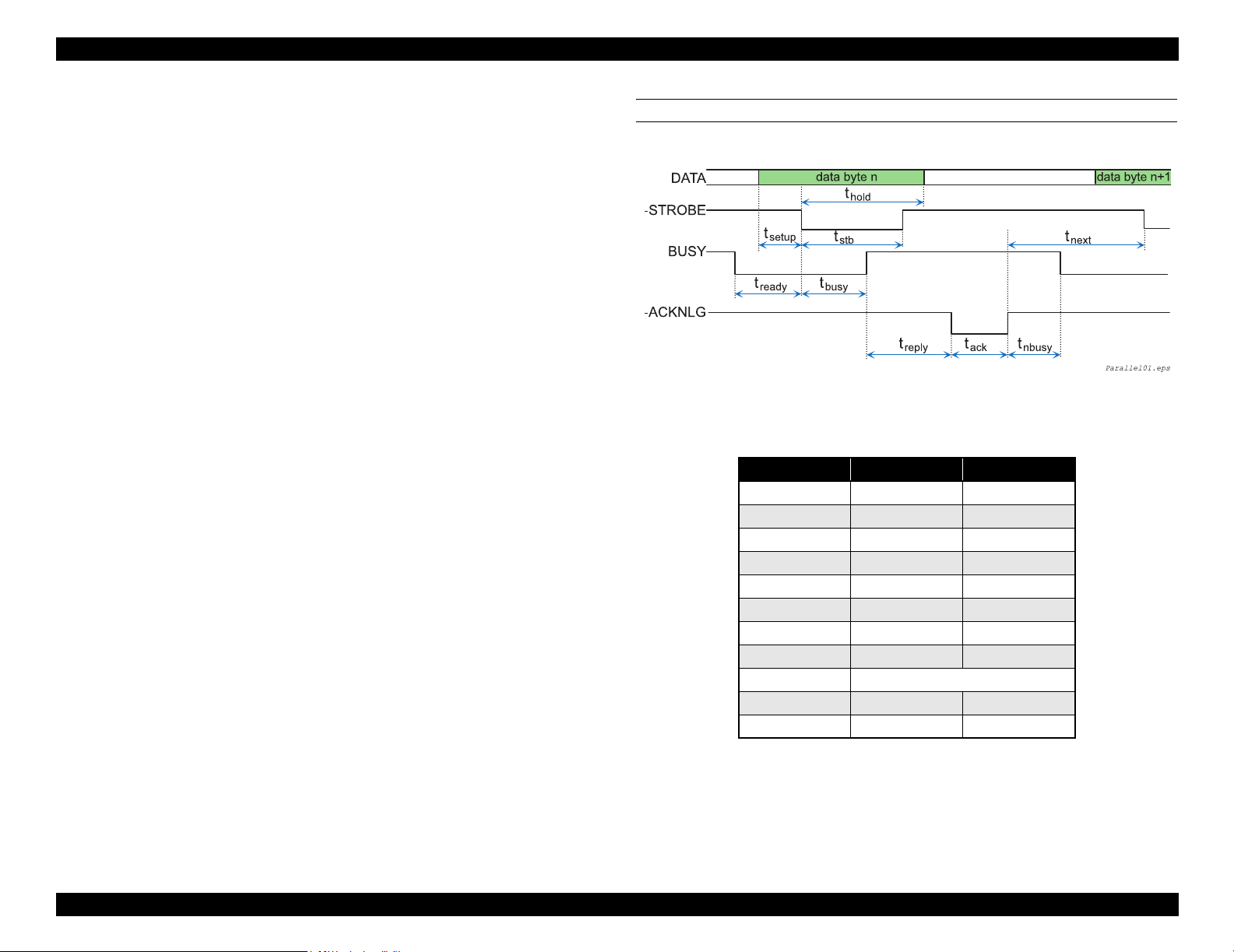
EPSON Stylus Pro 7600/9600 Revision A
6: Do not perform data transfer by ignoring the -ACKNLG signal or BUSY signal. (Data
transfer to this printer must be executed by checking the level of the -ACKNLG signal
or when the BUSY signal is “LOW”.)
7: Assign appropriate character codes to DATA0 ~ 7 of the interface connector (“1” for
open to GND and “0” for short to GND) and connect the BUSY signal line and the STROBE signal line. Then without using any external equipment, you can conduct
printing test of the printer including the interface circuit
PARALLEL INTERFACE TIMING CHART
Figure 1-19. Timing Chart
Table 1-54.
Parameter Minimum Maximum
tsetup 500 ns -
thold 500 ns -
tstb 500 ns -
tready 0 -
tbusy - 500 ns
1
tt-out*
2
tt-in*
treply 0 -
tack Typical 2us
tnbusy 0 -
tnext 0 -
- 120 ns
-200 ns
Note *1: Rise and fall time of every output signals
*2: Rise and fall time of every input signals
Product Description Interfaces 92
Page 93

EPSON Stylus Pro 7600/9600 Revision A
1.6.1.2 Nibble Mode
SPECIFICATION
Transmission mode: 8 bit parallel
Synchronization: By STROBE pulse
Handshaking: By BUSY and ACKNLG signal
Signal level: TTL compatible (IEEE1284Level 1 device)
Data trans. timing: Refer to the IEEE-1284 specification
Extensibility Request:
The printer responds affirmatively when the extensibility request values are 00H
or 04H, that mean,
00H Request Nibble Mode Reverse Channel Transfer.
04H Request Device ID; Return Data Using Nibble Mode Rev Channel
Transfer.
Device ID:
When IEEE1284.4 is valid
• <xx><xx>
(Character strings, depending on <Model Name>)
• MFG: EPSON;
• CMD: ESCPL2,BDC,D4;
• MDL: <Stylus Pro 7600-DYE/Stylus Pro 9600-DYE>;
• CLS: PRINTER;
• DES: EPSON<SP><Stylus Pro 7600-DYE/Stylus Pro 9600-
DYE>;(<SP>:space)
When IEEE1284.4 is not valid
• <xx><xx>
(Character strings, depending on <Model Name>)
• MFG: EPSON;
• CMD: ESCPL2,BDC;
• MDL: <Stylus Pro 7600-DYE/Stylus Pro 9600-DYE>;
• CLS: PRINTER;
• DES: EPSON<SP>T<Stylus Pro 7600-DYE/Stylus Pro 9600-DYE>;
(<SP>:space)
CONNECTOR PIN ASSIGNMENT AND SIGNALS
Table 1-55. Connector Pin Assignment and Signals (Nibble)
Pin
No.
10 28 PtrClk Out Printer clock signal.
11 29
12 28
13 28
14 30 HostBusy In Host busy signal.
31 30 -INIT In Not used.
32 29
36 30 1284-Active In 1284 active signal.
18 -- Logic H Out
35 -- +5V Out
17 -- Chassis GND -- Chassis GND.
16,33,
19-30
15,34 -- NC -- Not used
Note "*" : In/Out refers to the direction of signal flow from the printer's point of view.
Return
GND Pin
1 19 HostClk In Host clock signal.
2 20 DATA0 In
3 21 DATA1 In
4 22 DATA2 In
5 23 DATA3 In
6 24 DATA4 In
7 25 DATA5 In
8 26 DATA6 In
9 27 DATA7 In
-- GND -- Signal GND.
Signal Name In/Out * Function
The DATA0 through DATA7 signals
represent data bits 0 to 7, respectively. Each
signal is at high level when data is logical 1
and low level when data is logical 0.
PtrBusy
/DataBit-3,7
AckDataReq
/DataBit-2,6
Xflag
/DataBit-1,5
-DataAvail
/DataBit-0,4
Out
Out
Out
Out
Printer busy signal and reverse channel
transfer data bit 3 or 7.
Acknowledge data request signal and reverse
channel transfer data bit 2 or 6.
X-flag signal and reverse channel transfer
data bit 1 or 5.
Data available signal and reverse channel
transfer data bit 0 or 4.
Always “HIGH”. Pulled up to +5 V via 3.9 K
ohm resistor.
Always “HIGH”. Pulled up to +5 V via 1.0 K
ohm resistor.
Product Description Interfaces 93
Page 94

EPSON Stylus Pro 7600/9600 Revision A
1.6.1.3 ECP Mode
SPECIFICATION
Transmission mode: IEEE-1284ECP mode
Synchronization: IEEE-1284 specification
Handshaking: IEEE-1284 specification
Signal level: TTL compatible (IEEE1284Level 1 device)
Data trans. timing: IEEE-1284 specification
Extensibility Request:
The printer responds affirmatively when the extensibility request values are 10H
or 04H, that mean,
10H Request ECP Mode Reverse Channel Transfer.
14H Request Device ID; Return Data Using ECP Mode Rev Channel
Transfer.
Device ID:
When IEEE1284.4 is valid
• <xx><xx>
(Character strings, depending on <Model Name>)
• MFG: EPSON;
• CMD: ESCPL2,BDC,D4;
• MDL: <Stylus Pro 7600-DYE/Stylus Pro 9600-DYE> ;
• CLS: PRINTER;
• DES: EPSON<SP>T<Stylus Pro 7600-DYE/Stylus Pro 9600-DYE>;(<SP>:
space)
When IEEE1284.4 is not valid
• <xx><xx>
(Character strings, depending on <Model Name>)
• MFG: EPSON;
• CMD: ESCPL2,BDC;
• MDL: <Stylus Pro 7600-DYE/Stylus Pro 9600-DYE>;
• CLS: PRINTER;
• DES: EPSON<SP>T<Stylus Pro 7600-DYE/Stylus Pro 9600-DYE>;
(<SP>: space)
CONNECTOR PIN ASSIGNMENT AND SIGNALS
Table 1-56. Connector Pin Assignment and Signals (ECP)
Pin
Return
No.
GND Pin
119HostClk In
2 20 DATA0 In
3 21 DATA1 In
4 22 DATA2 In
5 23 DATA3 In
6 24 DATA4 In
7 25 DATA5 In
8 26 DATA6 In
9 27 DATA7 In
10 28 PeriphClk Out Data is transferred from a printer to a host.
11 29 PeriphAck Out
12 28 nAckReverse Out A printer does drive to Low and approve nReverseRequest.
13 28 Xflag Out X-flag signal and reverse channel transfer data bit 1 or 5.
14 30 HostAck In
31 30 nReverseRequest In
32 29 nPeriphReques Out This signal uses to produce a host interrupt.
36 30 1284-Active In 1284 active signal. “HIGH” in ECP mode
18 -- PeriphLogic Out Always “HIGH”. Pulled up to +5 V via 3.9 K ohm resistor.
35 -- +5V Out Always “HIGH”. Pulled up to +5 V via 1.0 K ohm resistor.
17 -- Chassis GND -- Chassis GND.
16,33
19-30
15,34 -- NC -- Not connected.
Note "*" : In/Out refers to the direction of signal flow from the printer's point of view.
Signal Name In/Out* Function
Data or address information are transferred from a host to a
printer.
The DATA0 through DATA7 signals represent data bits 0
to 7, respectively. Each signal is at high level when data is
logical 1 and low level when data is logical 0.
A printer uses this signal for a flow control of forward
direction. Also this signal offers the data bit 9 that use it to
judge whether or not it is information command
information or data to be output on the data signal of
reverse direction.
A host uses this signal for a flow control of reverse
direction. Also this signal offers the data bit 9 that use it to
judge whether or not it is information command
information or data to be output on the data signal of
forward direction.
This signal is made a low, to change a channel toward
reverse.
-- GND -- Signal GND.
Product Description Interfaces 94
Page 95

EPSON Stylus Pro 7600/9600 Revision A
1.6.2 USB interface
SPECIFICATION
Standard: “Universal Serial Bus Specifications Revision 2.0”
“Universal Serial Bus Specifications Revision 1.1”
“Universal Serial Bus Devices Class Definition for
Printing Devices Version 1.1”
Bit rate: 480Mbps (High Speed Mode)
12Mbp (Full Speed Device)
Data format: NRZI
Adaptable connector: USB Series B
Acceptable cable length: 2m
Device ID:
When IEEE1284.4 is valid
• <xx><xx>
(Character strings, depending on <Model Name>)
• MFG : EPSON;
• CMD : ESCPL2,BDC,D4;
• MDL : <Stylus Pro 7600-DYE/Stylus Pro 9600-DYE>;
• CLS : PRINTER;
• DES : EPSON<SP>T<Stylus Pro 7600-DYE/Stylus Pro 9600-
DYE>;(<SP>: space)
When IEEE1284.4 is not valid
• <xx><xx>
(Character strings, depending on <Model Name>)
• MFG : EPSON;
• CMD : ESCPL2,BDC;
• MDL : <Stylus Pro 7600-DYE/Stylus Pro 9600-DYE>;
• CLS : PRINTER;
• DES : EPSON<SP>T<ModeStylus Pro 7600-DYE/Stylus Pro 9600-
DYE>;(<SP>: space)
CONNECTOR PIN ASSIGNMENT AND SIGNALS
Table 1-57. Connector Pin Assignment and Signals (USB(FS)
Pin No Signal name In/Out Function description
1 VCC - Cable power. Maximum power consumption is
100mA
2 -Data bi-directional data
3 +Data bi-directional data, pull up to +3.3V via 1.5K ohm resistor
4 Ground - Cable ground
Figure 1-20. Pin Assignment
Product Description Interfaces 95
Page 96

EPSON Stylus Pro 7600/9600 Revision A
1.6.3 Optional Interface
Type-B interface (level 2, 1200mA type) is supported.
REPLY MESSAGE
(Case of using Type-B I/F card except above)
Card in Type-B slot 1:
Main-Type
Stylus Pro 7600:
MT48p,PW240cl10cpi,PRG(BNxxxx)rev,AP800ma,SPD0fast,GDI
Stylus Pro 9600:
MT48p,PW440cl10cpi,PRG(BWxxxx)rev,AP800ma,SPD0fast,GDI
NOTE: xxxx is F/W version.
Product-Name: <Stylus Pro 7600-DYE/Stylus Pro 9600-DYE>
Emulation-Type : ESCPL2-00
Entity-Type : EPSONLQ2
REPLY FOR OPTION COMMAND
Table 1-58. Reply List
Option command
number
00h No-operation Accept None
01h Start Hardware Reset Accept Execute OK
02h Start Software Reset Reject
03h Send Main System Type Accept
04h Send Name Data Reject
05h Inquire Name Data Accept
06h Send Product Name Accept
07h Send Software Emulation Type Accept
08h Complete Buffered Data Accept Check Condition
09h Stop Procedure Reject Execute OK
0Ah Return Buffered Data Reject
0Bh Send Entity Type Accept
0Ch Send Status Accept
0Dh Quit Procedure Reject
0Eh Inquire ASCII Message Reject
0Fh Send ASCII Message Accept None
10h-13h Unknown None
14h Inquire Emergency Message Accept Execute OK
15h Send Emergency Reply Accept
16h-1Fh Unknown None
20h-FFh Reserved None
Command name Reply-A Reply-B
Product Description Interfaces 96
Page 97

EPSON Stylus Pro 7600/9600 Revision A
SUPPORTED MAIN COMMAND AND SENDING TIMING
Table 1-59. Commands and Sending Timing
Main command
number
01h Start Software Reset -Init signal on the std. parallel
04h Send Name Data -Type B I/F Option command: 05h
07h Inquire Software Emulation
0Eh Inquire ASCII Message -Writing to DBIN-register
14h Inquire Emergency Reply -Reply for Emergency command
15h Send Emergency Message -Receive Emergency command
Command name Sending timing
-Type B I/F Option command: 01h
-Panel Reset
-Cold start
-Changing Software Emulation type
Type
Sending BDC-ST through DBIN register
When State-Reply is set “ON” by ST from Type-B I/F, sending BDC-ST through
DBIN register is started. When State-Reply is started, “Start” and “End” of BDC-ST
characters are announced by sending the Main command 0Eh.
Emergency command (BGJC):
“0x00”: Get device ID
“0x01”: Get all status
“0x08”:LFP Bi-D command (For acquisition of job information)
1.6.4 Supplements
PREVENTION HOSTS FROM DATA TRANSFER TIME-OUT
When data is received from the parallel interface or the type B interface while no error
has occurred (including the pause condition), the printer receives data a rate of 2 byte/
second while buffer free space is less than 16 kbytes in order to prevent host timeout.
When buffer free space is more than 32kbytes, the 2 byte/second receive rate is cleared,
and receive is halted when free space reaches 16 bytes, and returns to the 2 byte/second
rate when free space reaches 512 kbyte or more.
INTERFACE SELECTION
The printer has the parallel interface, the USB interface, the optional interface. These
interfaces are selected manually by the default setting mode or selected automatically.
Manual selection
One of 3 interfaces can be selected; the parallel interface, the USB interface, the
optional interface.
Automatic selection
Select a interface which the printer received data first after power ON. If it passes
10 seconds after interruption of data receiving, it will be idle status (any interface
is not selected) and will select a interface which the printer received data first.
Interface state and interface selection
When the parallel interface is not selected, the interface goes into the busy
status.
Only reverse communication can be done at this time.
When the printer is initialized or returned to the idle state, the parallel
interface becomes ready status, the USB interface becomes non NACK reply
status, and the option interface resets OFF-LINE bit of Main Status Register
(MNSTS).
INIT signal on the parallel interface is not effective while that interface is not
selected or nibble Mode , ECP Mode.
Product Description Interfaces 97
Page 98

EPSON Stylus Pro 7600/9600 Revision A
1.7 Optional Units and Consumables
1.7.1 Ink Cartridge
Selection of ink types, detection of cartridges and the amount of remaining ink are
controlled by CSIC.
C H E C K
P O I N T
SPECIFICATION
Type: Pigment / Dye ink cartridge
Form: Exclusive ink cartridge
Ink capacity:
110ml (Model Number: ICxx24)
220ml (Stylus Pro 9600 only) (Model Number: ICxx25)
Dimension:
110ml: 25.1 mm (W) × 165.8 mm (D) × 105.3 mm (H)
220ml: 25.1 mm (W) × 280.8 mm (D) × 105.3 mm (H)
Total weight:
110ml: approx. 200g
220ml: approx. 385g
Effective ink:
110ml: more than 97.0 g
220ml: more than 205.0 g
Color:
Photo Black, magenta, light magenta, cyan, light cyan, yellow Light Black
(pigment only), Matte black (pigment only)
Environment condition
Temperature: 10°C ~ 40°C
Relative humidity:: 5% ~ 85%
When installing the pigment ink cartridges, shake them gently
a couple of times beforehand to ensure the designed print
quality.
The 220 ml ink cartridges are supported only by Stylus Pro
9600.
Storage temperature
Condition temperature Remarks
Packed -30°C ~ 40°C Within 1 month when 40°C
Installed -20°C ~ 40°C Within 1 month when 40°C
Packed
transportation
C H E C K
P O I N T
If you remove an ink cartridge before it reaches the ink end state,
you should store it under the same ambient conditions as for the
printer body in such a way that the ink discharge opening is
protected from dust intrusion. The ink cartridge stored as such and
installed again can be used if it is within the term of availability.
-30°C ~ 60°C Within 1 month when 40°C
Within 120 hours when 0°C
Ink life: 2 years from production date
Print quality assured: pigment:
6 months after open / dye: 2 years from production date
INSTALLATION LOCATIONS
The locations to install the ink cartridges are assigned from the left side of the ink
cartridge holder as indicated below:
Table 1-60. Locations to Install Ink Cartridges
Dye Pigment 1 Pigment 2 Pigment 3
1K Photo KMatte KMatte K
2 K Lk Lk Matte K
3CCCC
4 M M M M
5LCLCLCLC
6 LM LM LM LM
7YYYY
C H E C K
P O I N T
Any ink cartridge other than the K and LK ink cartridges is
equipped with a wrong insertion preventing mechanism so that it
can be installed only at its position and in the correct orientation.
Product Description Optional Units and Consumables 98
Page 99

EPSON Stylus Pro 7600/9600 Revision A
1.7.4 Maintenance Tank
1.7.2 Cleaning cartridge
C H E C K
P O I N T
The cleaning cartridge is the same as the 220-ml ink cartridge in
shape except that it does not have the projection for a color block.
The maintenance tank is located in the lower space at the right side of the printer body
and constructed in such a way that the user can replace it when “maintenance tank full”
is detected.
Type: Exclusive maintenance tank for waste ink
Dimension: Width: 102.5 mm × Depth: 235 mm × Height:
79.5 mm
Type: Exclusive cleaning cartridge
Dimension: Same as 220ml exclusive ink cartridge
Capacity: Same as 220ml exclusive ink cartridge
Total weight: Same as 220ml exclusive ink cartridge
Effective cleaning solution: Same as 220ml exclusive ink cartridge
Environment condition: Same as 220ml exclusive ink cartridge
Storage temperature: Same as 220ml exclusive ink cartridge
Life: Same as 220ml exclusive ink cartridge
1.7.3 Draining cartridge
C H E C K
P O I N T
Type: Exclusive draining cartridge (no ink pack)
Dimension: Same as 110ml exclusive ink cartridge
Capacity: None
Total weight: 75g approx.
The draining cartridge is the same as the 110-ml ink cartridge in
shape except that it does not have the projection for a color block.
Capacity: 1000ml approx.
Total weight: TBD
Waste ink permitted limit: 650ml
Environment condition: TBD
Effective cleaning solution: None
Environment condition: Same as 110ml exclusive ink cartridge
Storage temperature: Same as 110ml exclusive ink cartridge
Life: Same as 110ml exclusive ink cartridge
Product Description Optional Units and Consumables 99
Page 100

OPERATING PRINCIPLES
CHAPTER
2
 Loading...