

Page 1

EPSON
EPSON AMERICA, INC.
INFORMATION
Product Support Bulletin
Subject: PriorityFax 2000/3000 Maintenance Switch Function Tables
Date: 8/8/90
Page: 1 of 8
The purpose of this document is to describe the PriorityFax 2000/3000
maintenance soft switch functions and supply instructions for accessing them.
ACCESSING THE MAINTENANCE MODE
1. In normal operation mode without a document inserted, press
“FUNCTION l 2 8 6 4” in the following sequence.
A. Press “FUNCTION” then immediately press “*“.
B. The unit will beep 3 times.
C. Immediately following the 3 beeps, press ’ 2 8 6 4 “.
NOTE: Numbers must be pressed in rapid succession.
PSB No: P-0070
Originator: VB
2. The unit will emit one long beep and the LCD will display
“MAINTENANCE”, indicating it is in maintenance mode.
If the LCD does not display ‘MAINTENANCE”, press “STOP”, wait for
the LCD to display the date and time, then try step 1 again. Call
Epson Product Support at 213-539-9955 if assistance is required.
3. There are 2 levels of soft switch functions accessible in the
maintenance mode. Table 1 lists the initial level functions. Tables 2,
3, and 4 list the second level functions. The tables are located at the
end of this document.
4. To activate one of the functions listed in Tab 1, enter the initial
maintenance mode. Enter the two digit ‘Switch Number” with the keys
on the control panel. The unit will perform the function and return to
the initial maintenance mode.
The functions marked ‘NOT USED’ are either not available or require
Specialized equipment. They should only be accessed by an
authorized Epson Customer Care Center.
Page 2

PSB No: P-0070
Page: 2 of 8
5. Pressing the “STOP” key in the initial maintenance mode returns the
unit to normal operation.
Pressing the “STOP” key when only one digit has been entered returns
the unit to the initial maintenance mode.
The unit returns to the initial maintenance mode when the number
entered does not correspond to a function listed in Table 1.
EEPROM PARAMETER INITIALlZATION
Function
Sets the EEPROM memory content, user switch data, and soft switch data
to the factory default settings.
Operation Method
1. To activate the EEPROM Parameter Initialization, enter the initial
maintenance mode. Press the “0” key one time and then press the “1”
key one time.
The LCD will display “PARAMETER INIT”.
2. Upon completion of the EEPROM Parameter Initialization, the unit Will
emit one long beep indicating it has returned to the initial maintenance
mode.
EEPROM
Function
The unit spans a blank white sheet of paper to establish a white level
reference point that is used for comparison of black
Operation Method
1.
2.
3.
WHITE LEVEL DATA INITIALIZATION
and white
To activate the EEPROM White Level Data
maintenance mode. Load a blank white sheet of paper in the
document slot.
Press the “0” key one time and then press the “2” key one time. The
LCD will display “WHITE LEVEL
Upon completion of the EEPROM white Level Data Initialization, the unit
will emit one long beep indicating it has returned to the initial
maintenance mode.
INIT”.
Initialization,
levels.
enter the
initial
Page 3
PSB No: P-0070
Page: 3 of 8
EST PATTERN
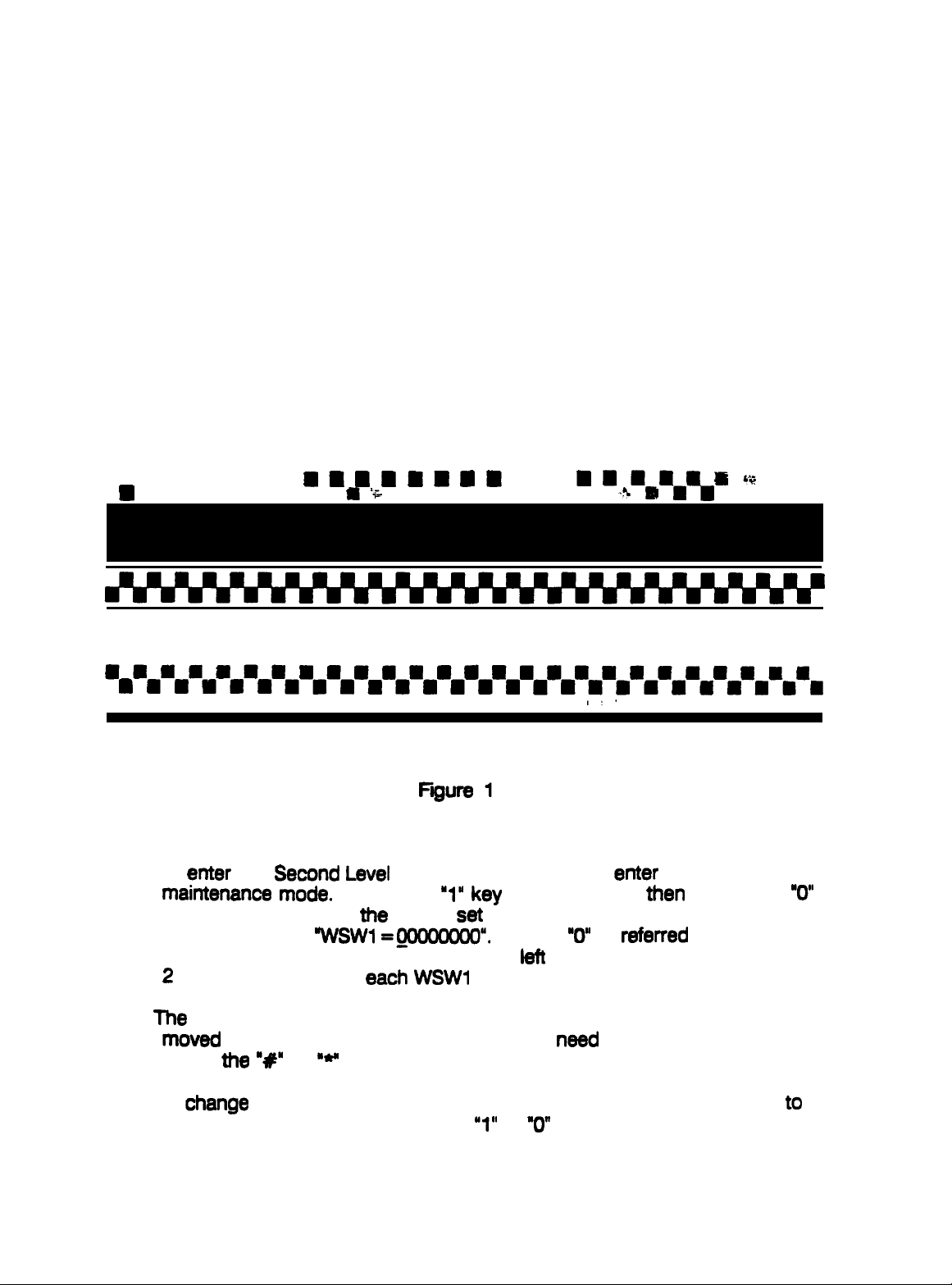
1. To print the test pattern, enter the initial maintenance mode. Press the
“0” key one time and then press the “9” key one time. The unit will
continue to display “MAINTENANCE” on the LCD and print a test
pattern as shown in Figure 1.
2. Upon completion of printing the test pattern, the unit will emit one long
beep indicating it has returned to the initial maintenance mode.
n
I
a
n
-mirmvm
a a a a a a m
n l
I
%
n l
m
rn"%rnrnrn,
15
8
n n
‘@
n n
l mmmmmmmmmmmmmmmmmmmmmmmmm
n
n n n n n n n n n n n n n n n n n n n n n n n n n
mmaammmmmmmmmmmmmmmmmmmmmm
•~lam~mmm~~~~m~m~m~mm~~mmm
SECOND LEVEL SOFT SWITCH FUNCTIONS
1. To
2.
8nt8r
the
Second
maintenance mode.
key one time. When
LCD will display
‘Switch” and they are numbered from
2
lists the function of
The
cursor, which is the line under the first 0 on the LCD, can be
moved
using
under any of the 8 characters that
ttl8 “R”
or
b/81
Soft Switch Functions,
Press the
the
unit is
%/SW1 =,oooooooo”.
8aCh WSWl
“**
key.
‘1” k8y
,
one time and
set
to the factory default settings, the
Each
left
switch.
,I*
8nt8r
the initial
then
press the
“0”
is
r8ferred
to right 1 through 8. Table
need
to be changed by
to as a
“0”
3. To
Change
be changed and press either the
a function place the cursor under the switch that needs
“1”
or
“0”
key as necessary.
to
Page 4

PSB No: P-0070
Page: 4 of 8
4.
Pressing the “Next” key will store the values of
and make
factory default settings, the LCD will display “WSW2=
3 lists the function of
5.
In this mode, every time
settings are finalized and the next switch bank,
WSW3, in that order, is made available. Table 4 lists the function of
each WSW3 switch.
6.
If
the “SF
The unit then emits one long
initial maintenance mode.
7.
When
the “STOP” key is
Th8
Unit
initial
SECOND LEVEL SOFT SWITCH FUNCTION DESCRIPTIONS
maintenance
“WSW2”
key is pressed, the current switch bank settings are saved.
then emits
available for change.
8aCh
WSW2 switch.
one
mode.
the “NEW
beep
preSSed,
long b88p
key is pressed, the Current switch
indicating that it has returned to the
any changes made are canceled.
indicating that it has
When
WSWl
the unit is set to the
WSWl,
in the EEPROM
113DOOOO”.
WSW2 or
r8tUtTI t0
Table
the
Tab18
2 Switch 1: Overseas communication
Setting
signal that suppresses echoes, instead of a 2100
echo suppressor (ES). Suppressing
reliable method
Table 2 Switches 2 & 3: Overseas communication
When
DIS signal sent from the calling station for suppressing echoes. Note:
Some called
When
Hz signal for 3
operation prevents
enables a no-
Table 2
When this
remat station when th8
the hand
testing 2
switch 1 to a “1” allows the unit to acknowledge the 1100 Hz
of establishing communications.
switch 2 is
models may cause an
both switches 2 and 3 are set to
Switch 4:
8witoh
set
is on - hook or off - hook.
fax
machines when they
set
to ‘1” and 3 is
Seconds
the called
canier state
Direct
is
upon detection of the DIS V.21
connection
set
to 1,
“START”
station
until
the
from receiving its own DIS and
th8
unit transmits a
mod8
unit
k8y
are
mod8 (reception)
Hz which
th8 8Cho8S provides
mod8
set
to
“O”,
the unit
error by receiving an
“l”,
the unit
starts
receiving signals
is pressed,
This mode is used for Cross
connected directly to
r8gardl8S8
a more
(Transmission)
transmits
subsequ8ntial
disables the
ignores
echoed
flag.
of whether
8aCh other.
the
DIS.
an 1100
This
DIS.
from the
Page 5

PSB No: P- 0070
Page: 5 of 8
Table 3 -Switches 1 - 4: Start/End Transmission speed in G3 mode
The starting and ending transmission speed can be set separately in
G3 overseas communication mode. If there is excessive noise,
decrease the starting
Speed.
transmission of the document
Increase
takes
the ending
Sp88d
if
th8
too long. These settings are
independent of the overseas communications mode (Table 2 switches 2
and 3).
-
Table 4
Switches 3 & 4: Modem Equalizer
These switches are
compensate for line loss.
uSed
for setting the Modem
m8
function section of Table 4 lists the
relationship between the line loss and the appropriate switch setting
that compensates for that loss.
Table 4
-
Switches 5- 8: Modem Attenuator
These switches are used to adjust the transmission level attenuation.
The amount of attenuation is
switch to “1”.
For example, if switches 5 and 6 are set to
switches 7 and 8 are set to
m8
maximum attenuation with all the switches set to
When a switch in this section of table 4 is
is 0
dB.
accumulative
“O”,
the accumulative attenuation is 12
when setting more than one
set
to
SECOND LEVEL SOFT SWITCH DATA PRINTOUT
Operation Method
1. To print the “SYSTEM
Second
Level
Soft Switch Data,
Press the “1” key twice.
CONFIGUBATION
LIST” which contains the
8nt8r th8
Th8
LCD will continue to display
initial maintenance
“MAINTENANCE” and the ‘SYSTEM CONFIGURATION LlSP will be
printed.
Equalizer
‘0”
that switch value
“1’
is 15
to
“1”
and
mode.
dB.
dB.
2. Upon completion of printing the “SYSTEM CONFIGURATION
unit will emit one long
beep
indicating it has
rstumed
to the initial
UST’, the
maintenance mode.
Page 6

PSB No: P- 0070
Page: 6 of 8
LCD FUNCTION TEST
Operation method
1. To activate the LCD Function Test, enter the initial maintenance mode.
Set the “Ring Delay” switch to the “4” position.
2. Press the “1” key one time and then press the “2” key one time. The
LCD will display an oblique pattern (see Figure 2).
3. Confirm that the LCD changes from the oblique, to the all black, and
then the all white pattern every time the
“START’
key is pressed.
4. set the “Ring
long
beep indicating it has
Delay”
switch to the
returned to th8
Figure 2
“1”
position.
m8
initial
unit will emit one
maintenance mode.
Page 7

PSB No: P- 0070
Page: 7 of 8
TAD RAM CHECK
Function
This function checks whether the TAD (Telephone Answering Device) RAM
functions correctly.
Operation Method
1. To activate the TAD RAM CHECK, enter the initial maintenance mode.
Press the
LCD will display “TAD RAM CHECK”.
2. Upon completion of the test, the unit will emit one long beep indicating
it has returned to the initial maintenance mode.
3. If an error is detected during the TAD RAM check, the unit will emit a
beep and the LCD will display “TAD RAM ERROR”.
4. Press the “STOP” key while the LCD is displaying
the unit will emit one long
maintenance mode.
(PF3000
“1”
key one time and then press the
only)
beep
indicating it has
“3”
key one time. The
‘TAD
RAM ERROR”,
returned
to the initial
Page 8

PSB No: P- 0070
Page: 8 of 8
Switch
bkmhr
I I
tuution
Description
01
EEPROl PARMETER
IYfTlALI2ATIOY
I
07
lloTusED
I NOTUSED
09 TEST PATTERR
T&k
tu’tch
Setting
2
0
1
0.0
l,O
l,l
0
1
faction
OFT
al
Mf
Imores
lrmsmitr
DR
DIS once
DFF
1100nr
Suitch
Y-r
I
2,3 WERSEAS
4
S-8
NOT USED
I
Ooscriptim
OVERSEAS
NODE mceptian)
MDDE (lrmmission)
DIRECT
CC+WRIUTI#
cmkNI1cATIoy 2.3
CDMWECTIDR WK)E
11
SECOND
LEVEL RUITCN
DATA
PRIYTM
I
12
~LtXl ClWTIOU CIIEO:
witches
witch l
e
to
zwo
xoro
l ttels8stiorl
Idlo 4
 Loading...