

Page 1

®
EPSON
POWERSPAN.
User’s Guide
Printed on recycled paper with 10% post-consumer content m02184
@
Page 2

IMPORTANT NOTICE
DISCLAIMER OF WARRANTY
Epson America makes no representations or warranties, either express or implied, by or
with respect to anything in this manual, and shall not be liable for any implied warranties
ofmerchantability and fitness for a particular purpose or for any indirect, special, or
consequential damages. Some states do not allow the exclusion of incidental or
consequential damages, so this exclusion may not apply to you.
COPYRIGHT NOTICE
All rights reserved. No part of this publication may be reproduced, stored in a retrieval
system, or transmitted, in any form or by any means, electronic, mechanical,
photocopying, recording, or otherwise, without the prior written permission of Epson
America, Inc. No patent liability is assumed with respect to the use of information
contained herein. Nor is any liability assumed for damages resulting from the use of the
information contained herein. Further, this publication and features described herein are
subject to change without notice.
TRADEMARKS
EPSON and PowerSpan are registered trademarks of Seiko Epson Corporation
The power-on diagnostic error messages and tone codes in Appendix A are copyright
1985-1992, Phoenix Technologies, Ltd.
General notice: Other product names used herein are for identification purposes only and
may be trademarks of their respective owners. EPSON disclaims any and all rights in
those marks.
Copyright 0 1994 by Epson America, Inc.
Torrance, California, USA
ii
400363600
10/ 94
Page 3

Important Safety Instructions
Read all of these instructions and save them for later reference. Follow
all warnings and instructions marked on the computer.
.
Unplug the computer before cleaning. Clean with a damp cloth only.
Do not spill liquid on the computer.
.
Do not place the computer on an unstable surface or near a radiator
or heat register.
.
Do not block or cover the openings in the computer’s cabinet. Do not
insert objects through the slots.
.
Use only the type of power source indicated on the computer’s label.
.
Connect all equipment to properly grounded power outlets. Avoid
using outlets on the same circuit as photocopiers or air control
systems that regularly switch on and off.
.
Do not let the computer’s power cord become damaged or frayed.
.
If you use an extension cord with the computer, make sure the total
ampere rating of the devices plugged into the extension cord does
not exceed the cord’s ampere rating. Also, make sure the total of all
devices plugged into the wall outlet does not exceed 15 amperes.
.
Except as specifically explained in this Users Guide, do not attempt to
service the computer yourself.
.
Unplug the computer and refer servicing to qualified service
personnel under the following conditions:
If the power cord or plug is damaged; if liquid has entered the
computer; if the computer has been dropped or the cabinet damaged;
if the computer does not operate normally or exhibits a distinct
change in performance. Adjust only those controls that are covered
by the operating instructions.
.
If you plan to use the computer in Germany, observe the following:
To provide adequate short-circuit protection and over-current
protection for this computer, the building installation must be
protected by a 16 Amp circuit breaker.
Beim Anschlul3
sichergestellt werden, dab die Gebaudeinstallation mit einem
16
A
Uberstromschutzschalter abgesichert
des Computers an die Netzversorgung muh
ist.
Page 4

Importantes instructions de sécurité
Lire attentivement
consulter en
cas de
les
instructions suivantes et
les
conserver pour
besoin. Observer soigneusement tous
les
avertissements et directives marques sur l’ordinateur.
l
Debrancher l’ordinateur avant de le nettoyer. N’utiliser qu’un chiffon
humide.
l
Ne pas placer l’ordinateur sur une surface instable ni pres dune
Veiller a ne
pas renverser de liquides sur l’appareil.
source de chaleur.
l
Ne pas bloquer ni couvrir
introduire
l
Utiliser seulement le type de source d’alimentation
d’objets
dans
les
orifices d’aeration de l’appareil. Ne pas
les
ouvertures.
Clectrique
sur l’etiquette.
l
Tout l’equipement doit Ctre branche sur des prises de courant avec
contact de terre. Ne jamais utiliser une prise sur le meme circuit
qu’un appareil
a
photocopies ou un systeme de controle de
ventilation avec commutation marche-arret automatique.
l S’assurer
que le cordon d’alimentation de l’ordinateur n’est pas
abime ni effiloche.
l
Dans le
s’assurer que l’intensite en amperes requise pour tous
branches sur ce cordon
cordon.
cas ou on
S’assurer
utilise un cordon de rallonge avec l’ordinateur,
les
appareils
ne
soit pas superieure
aussi que cette intenste ne depasse jamais
a la
capacite du
la
de 15 amperes pour l’ensemble des appareils.
les
indique
somme
l
Sauf dans
ne
pas essayer d’entretenir
l
Debrancher l’ordinateur et contacter un technicien qualifie dans
les cas
specifiques expliques dans ce manuel de l’usager,
ou de
reparer l’ordinateur soi-meme.
circonstances suivantes:
Si le cordon ou
l’interieur de l’appareil; si on
est endommage;
la
prise sont abimes; si un liquide
a
laisse tomber l’appareil ou
si
l’ordinateur
ne
fonctionne pas normalement ou
a
pen&C
a
si le
fonctionne dune man&e tres differente de l’ordinaire. N’ajuster que
les
commandes d&rites dans
l
Pour utiliser l’ordinateur en Allemagne,
les
directives.
il
est necessaire que le
batiment soit muni d’un disjoncteur de 16 amperes pour proteger
l’ordinateur contre
les
courts-circuits et le survoltage.
les
bonier
Page 5

Contents
Introduction
SCSI Subsystem
Software
Features of This Manual
Where to Get Help
. . . . . . . . . . . . . . . . . . . . . . . . . . . . . . . . . . . . . . . . 3
CompuServe On-line Support
Chapter 1
Preparing to Set Up Your System
Installation Overview
Setting the Voltage Selector Switch
Installing Optional Equipment
Connecting Peripheral Devices
Turning On the System
Configuring Your System
Equipment Log
Chapter 2
Starting the Program
Selecting Options
Selecting Settings
Hard Disk Drive Types
Exiting SETUP
................. . . . . . . . . . . . . . . . . . . . . . . . . . . . . . . . .2
. . . . . . . . . . . . . . . . . . . . . . . . . . . . . . . . . . . . . 3
. . . . . . . . . . . . . . . . . . . . . . . . . . . . . . . . . . . . 4
Setting Up Your-System
...... . . . . . . . . . . . . . . . . . . . . . . .
...... . . . . . . . . . . . . . . .
...... . . . . . . . . . . . . . . . .
...... . . . . . . . . . . . . . . . .
...... . . . . . . . . . . . . . . .
...... . . . . . . . . . . . . . . . . . . . . .
Running the SETUP Program
......................
.....................
........................
..................
.......................
........ . . . . . . . . . . . . . . . . . . . . . .5
. . . . . . . . . . . . . . . . . . ......
...... . . . . . . . . . . . .
1-1
1-2
1-4
1-5
1-6
1-8
1-10
1-11
2-2
2-4
2-4
2-13
2-16
Chapter 3
How to Use This Chapter
The Configuration Process
Using Configuration Files
Using the Keyboard
Using a Mouse
Using On-line Help
Running the EISA Configuration Utility
.........................
.....................
.....................
...................
......................
......................
3-3
3-4
3-4
3-5
3-5
3-6
V
Page 6

Configuring Your System
...............
Starting the Program ...............
Setting the Date and Time
Performing the Configuration Steps
Adding or Removing a Board
Defining the Configuration Settings
............
......
..........
......
Hard Disk Drive Types ..............
Using Advanced Configuration Options
Using Alternate Configuration Files
Creating an Alternate SCI File
Loading an Alternate SCI File
Using Special Modes
Using the SD Command
Using the CF Command
..................
.............
.............
.........
..........
..........
Copying the Configuration Files to a Hard Disk
....
. . . . . . .
3-7
3-7
3-8
3-9
3-11
3-11
3-25
3-28
3-29
3-30
3-31
3-31
3-32
3-34
3-36
Chapter 4
Working Comfortably
Using the Right Furniture
Positioning Your Monitor
Lighting Your Workspace
Using the Keyboard and Mouse
Maintaining Good Posture and Work Habits
Locking the Computer’s Cover
Locking the Front Panel Door
Disabling the Keyboard and Mouse
Using the Password Features
Using Your Computer
................
...........
...........
. . . . . . . . . . . . .
........
. . . . . . . .
...........
............
........
............
Setting Passwords ................
Entering Passwords ...............
Changing or Deleting Passwords
Locking the Keyboard
................
Changing the Processor Speed
Entering Keyboard Commands
Using the EISA System Utilities
Controlling the Speaker
Controlling the Cache
...............
................
Using the Security Features
...........
.............
.......
........
........
4-2
4-2
4-3
4-4
4-4
4-5
4-6
4-7
4-8
4-9
4-10
4-12
4-13
4-16
4-17
4-18
4-19
4-20
4-21
4-23
vi
Page 7

Installing the Video Drivers and Utilities
Installing MS-DOS Video Drivers and Utilities
Installing Windows 3.1 Drivers
Using the SCSI Subsystem
Installing SCSI Terminators
Installing SCSI Devices
Configuring the SCSI Subsystem
Installing SCSI Software
Using Special Configurations
Operating Your Computer from a Remote Location
. . . . . . . . . . . . . . . . . . . . . . . .
. . . . . . . . . . . . . . . . . . . . . . . .
. . . . . . . . . . . . . . . . . . . . . . . .
. . . . . . . . . . . . . . .
. . . . . . . . . . . . . . . . . . . . . . . .
. . . . . . . . . . . . . . . . . . . . . . . .
. . . . . . . . . . . . . . . . . . . . . . . .
. . . . . . . . . . . . . . . . . . . . . . .
. . . . . . . . . . . . . . . . . . . . . . . .
. . . . . . . . . . . . .
Chapter 5 Accessing Internal Components
4-24
4-24
4-25
4-26
4-27
4-27
4-28
4-28
4-29
4-30
Special Precautions . . . . . . . . . . . . . . . . . . . . . . . . . . . . . . . . .
Removing the System Covers . . . . . . . . .
Removing the External Side Cover . . . . . . . . .
Removing the Internal Main System Board Cover . . . . .
Replacing the System Covers . . . . . . . . . .. . . . . . . . . . . . . . . . . . . . . .5-5
Replacing the Internal Main System Board Cover . . . .
Replacing the External Side Cover . . . . .
Removing the Front Panel . . . .
Replacing the Front Panel . . . .
. . . . . . . . . . . . . . . . . . . . . . . . . 5-8
. . . . . . . . . . . . . . . . . . . . . . . . . 5-9
. . . . . . . . . . . . . . . . . . . . . . . . .
. . . . . . . . . . . . . . . . . . . . . . . . .
. . . . . . . . . . . . .
. . . . . . . . .
. . . . . . . . . . . . . . . . . . .
5-1
5-2
5-3
5-4
5-5
5-7
Chapter 6 Installing and Removing Options
Main System Board Map ...................
Removing the CPU Card ...................
Installing the CPU Card ...................
Installing the Dual-Pentium 66 ASIC Chip ......
Installing an Option Card
Removing an Option Card
Using the VGA Feature Connector
Memory Modules .......................
Installing Memory Modules
Removing Memory Modules
Adding Video Memory ....................
Setting Main System Board Jumpers
..................
..................
.............
.................
................
............
6-2
6-3
6-4
6-6
6-7
6-10
6-10
6-11
6-12
6-14
6-15
6-18
vii
Page 8

Chapter 7
Installing and Removing Disk Drives
Using the Correct Drive Bay . . . . . . . . . . . . . . . . . . . . . . . . . . . . .
Installing a Drive in an External Bay . . . . . .
Removing a Drive from an External Bay . . . .
Installing and Removing an IDE Hard Disk Drive . .
Removing the IDE Drive Bay Assembly . . . .
Installing an IDE Drive. . . . . . .
Removing an IDE Drive. . .
. . . . . . . . . . . . . . . . . . . . . . .
Replacing the IDE Drive Bay Assembly. . .
Connecting the IDE Ribbon and Power Cables
Installing a SCSI Drive. . . . . . . . .
. . . . . . . . . . . . . . . . . . . . . . . . . . . . . .
Installing the SCSI Ribbon and Power Cables
Removing a SCSI Drive. . . . . . .
. . . . . . . . . . . . . . . . . . . . . . .
. . . . . . . . . . . . . . . . . . . . . .
. . . . . . . . . . . . . . . . . . . .
. . . . . . . . . . . . . . . . . .
. . . . . . . . . . . . . . . . . . .
. . . . . . . . . . . . . . . . . . . . . .
. . . . . . . . . . . . . . . . . . .
. . . . . . . . . . . . . . . .
. . . . . . . . . . . . . . . . .
Appendix A Troubleshooting
Identifying Your System
Error Messages
.........................
Power-on Diagnostic and Boot Errors
Run-time Error Messages
Error Tone Codes
Power or Lock-up Problems
Password Problems
Keyboard Problems
Monitor Problems
Diskette Problems
Diskette Drive Problems
Hard Disk Problems
Software Problems
Printer Problems
Option Card Problems
Memory Module Problems
Mouse Problems
SCSI Drive Problems
....................
.........
................
.....................
..................
.......................
.......................
.......................
.......................
....................
......................
.......................
........................
.....................
..................
........................
......................
7-2
7-3
7-8
7-9
7-10
7-11
7-12
7-13
7-14
7-18
7-22
7-25
A-1
A-3
A-3
A-14
A-15
A-17
A-19
A-21
A-22
A-23
A-23
A-24
A-25
A-26
A-26
A-27
A-28
A-29
Viii
Page 9

Appendix B Specifications
Main System Board
CPU Card
Interfaces
Controllers
Keyboard
Mass Storage
Physical Characteristics
Environmental Requirements
Power Supply
System Memory Map
Input/ output Addresses
DMA Channels
Glossary
Index
. . . . . . . . . . . . . . . . . . . . . . . . . . . . . . . . . . . . . . . . . . . . . . .
. . . . . . . . . . . . . . . . . . . . . . . . . . . . . . . . . . . . . . . . . . . . . . .
System Interrupts
. . . . . . . . . . . . . . . . . . . . . . . . . . . . . . . . . . . . . . .
. . . . . . . . . . . . . . . . . . . . . . . . . . . . . . . . . . . . . . . . . . . . . . .
. . . . . . . . . . . . . . . . . . . . . . . . . . . . . . . . . . . . . . . . . . . . . . .
. . . . . . . . . . . . . . . . . . . . . . . . . . . . . . . . . . . . . . . . . . . . . . .
. . . . . . . . . . . . . . . . . . . . . . . . . . . . . .
. . . . . . . . . . . . . . . . . . . . . . . .
. . . . . . . . . . . . . . . . . . . . . . . . . . . . . . . . . .
. . . . . . . . . . . . . . . . . . . . . . . . . . . . . .
. . . . . . . . . . . . . . . . . . . . . . . . . . . . . . . . .
. . . . . . . . . . . . . . . . . . . . . . . . . . . . . . . . . .
. . . . . . . . . . . . . . . . . . . . . . . . . . . . . . . . . .
B-1
B-2
B-2
B-3
B-4
B-4
B-4
B-5
B-5
B-7
B-8
B-10
B-11
ix
Page 10

Introduction
The EPSON®PowerSpan® computer is a powerful, versatile
system ideally suited for use as a network file server. It
incorporates the latest EISA (Extended Industry Standard
Architecture) technology and a built-in dual-SCSI (Small
Computer System Interface) subsystem in a convenient tower
design. Its exceptional features and flexibility enable you to use
the most advanced peripheral devices and software while
maintaining full compatibility with ISA technology.
Your system includes the following features:
0
8MB of RAM on a single inline memory module (SIMM),
expandable to 128MB using 1MB, 2MB, 4MB, 8MB, 16MB:
or 32MB single- or double-sided SIMMs
0
A removable card containing one of the following CPUs:
l Intel
®
486DX2/66 CPU with 8KB internal and 128KB
secondary cache memory and an integrated math
coprocessor
l Intel Pentium
®
60 MHz or 90 MHz CPU card; the
60 MHz Pentium CPU has 256KB of cache and
the 90 MHz Pentium CPU has 512KB of cache
l Intel Dual Pentium 66 MHz CPU card for use with
0
One built-in parallel and two built-in serial interfaces, plus
®
UNIX® MPX only
SCO
a built-in VGA controller providing standard VGA
resolutions
0
IBM®PS/2®compatible mouse port and keyboard port
0
Eight EISA bus master expansion slots (compatible with
32-bit EISA cards and 8- or 16-bit ISA cards)
Intro-1
Page 11

SCSI-II subsystem consisting of two SCSI channels with
interfaces built into the main system board
IDE hard disk drive interface for two hard disk drives
Diskette drive controller for two diskette drives
Mass storage space for up to nine half-height drives: two
internal bays for IDE hard disk drives or SCSI drives, four
internal bays for SCSI drives, and three externally
accessible bays for diskette, tape, or CD-ROM drives.
The built-in interfaces let you connect basic peripheral devices
directly to the computer, leaving the expansion slots for
optional devices such as a modem and a networking card.
Your computer provides a 32-bit wide EISA bus that supports
64-bit processors by employing advanced bit-interleaving
technology. In addition, the fast EISA burst mode capability
enables data transfers of up to 66MB of data per second
through the EISA bus.
In addition, your computer offers multiple-level security
features to protect both the hardware and software from
unauthorized user access.
SCSI Subsystem
Your computer’s SCSI controller can burst 32-bit data transfers
through the EISA bus at up to 33MB per second. Its two SCSI
channels (buses) provide support for up to 14 differential pair
or single-ended SCSI devices (seven on each channel). You can
easily configure the SCSI controller, BIOS, SCSI ID
attributes for both channels using the EISA Configuration
utility. In addition, your system comes with SCSI software and
drivers for DOS, Microsoft
NetWare,® Windows NT, and SCO UNIX.
Intro-2 Introduction
®
Windows,TM OS/2,® Novell
S, and other
®
Page 12

Included with your system is a System Configuration diskette
containing the EISA Configuration utility and various EISA
System Utilities. These programs allow you to configure your
computer, SCSI subsystem, and EISA option cards, as well as
customize many other system features.
In addition, a SETUP program is provided in your system
BIOS so you can easily configure your computer if you have
not installed any EISA option cards, are not using the SCSI
subsystem, or are operating your system without a diskette
drive.
Also included are two Video Driver diskettes containing
installation programs and video drivers and utilities for
Windows 3.1 and many popular MS-DOS
®
applications.
The three SCSI driver diskettes contain SCSI software and
device drivers for various versions of DOS, Windows, OS/2,
NetWare, Windows NT, and UNIX. See Chapter 4 of this
manual and the X-Series SCSI Software Users Guide for the
AIC-7770 for instructions on installing and using the SCSI
software.
Features of This Manual
This manual explains how to set up, configure, and operate
your computer, as well as how to install optional equipment.
It does not cover your operating system; see your operating
system manual for instructions on installing and using it.
Although you should be sure to follow the steps in Chapters 1,
2, and 3 to set up and configure your system, you do not need
to read everything in this book. See the following chapter
summaries to find the sections you need.
Introduction Intro-3
Page 13

Chapter 1 provides instructions for setting up your system.
Chapter 2 describes how to run the SETUP program to
configure your computer when you do not have a diskette
drive or did not install any EISA option cards.
Chapter 3 describes how to run the EISA Configuration utility
to configure your computer when you have installed EISA
option cards.
Chapter 4 provides instructions for certain operating
procedures, such as locking the computer’s cover, using the
password features, and changing the operating speed.
Chapter 5 describes how to remove and replace the system
covers and the front panel to access the internal components.
Chapter 6 describes how to install and remove options.
Chapter 7 describes how to install and remove disk drives.
Appendix A contains troubleshooting tips.
Appendix B gives the technical specifications for the computer.
At the end of the manual, you’ll find a
a list of EPSON U.S. and international marketing locations.
Glossary, an Index, and
Where to Get Help
EPSON provides customer support and service through a
network of Authorized EPSON Servicers. If you need technical
assistance with the installation, configuration, and operation of
your EPSON product, contact your EPSON dealer or
Authorized EPSON Servicer.
Intro-4 Introduction
Page 14

You can also contact the EPSON marketing location nearest
you for customer support and service. International marketing
locations are listed at the end of this manual.
When you call for technical assistance, be ready to identify
your system and its configuration, and provide any error
messages to the support staff. See Appendix A for more
information.
If you need help with any software application program you
are using, see the documentation that came with that program
for technical support information.
CompuServe On-line Support
If you have a modem, the fastest way to access helpful tips,
specifications, drivers, application notes, tables for DIP switch
or jumper settings, and bulletins for EPSON products is
through the Epson America Forum on CompuServe.
If you are not currently a member of CompuServe, you are
eligible for a free introductory membership as an owner of an
EPSON product. This membership entitles you to:
®
0
An introductory $15 credit on CompuServe
0
Your own user ID and password
0
A complimentary subscription to CompuServe Magazine,
CompuServe’s monthly publication.
To take advantage of this offer, call the following U.S.
telephone number: (614) 529-1611 or your local CompuServe
access number.
If you are already a CompuServe member, simply type
GO EPSON at the menu prompt to reach the Epson America
Forum.
Introduction Intro-5
Page 15

Chapter 1
Setting Up Your System
This chapter describes how to set up and start using your
computer system for the first time. Before you set up your
system, be sure to read the “Important Safety Instructions”
at the beginning of this manual.
Preparing to Set Up Your System
It is important to choose a safe, convenient location for your
system that provides the following:
A flat, hard surface. Place the computer on an anti-static
mat if the surface is carpeted.
Good air circulation. Leave several inches of space around
the computer so air can move freely for proper cooling.
Moderate environmental conditions. Select a cool, dry, area
and protect your computer from humidity, dust, and
smoke. Avoid direct sunlight and other heat sources.
No electromagnetic interference. Do not place your system
too close to any device that generates an electromagnetic
field or creates electrical noise, such as a telephone, air
conditioner, large fan, radio, TV, or large electric motor.
Access to appropriate power sources. Connect all your
equipment to an appropriate source. (See “Setting the
Voltage Selector Switch” on page 1-4 for information about
setting the correct voltage.)
Setting Up Your System
1-1
Page 16

If the power cord supplied with your system is not compatible
with the AC wall outlet in your region, obtain a suitable power
cord that meets the following criteria:
0
The power cord must be rated for at least 125% of the
current rating of the AC voltage system. For more
information, see Appendix B.
0
The power cord connector that plugs into the wall outlet
must be an appropriately grounded male plug.
0
The power cord connector that plugs into your system
must be an IEC type CEE-22 female connector.
0
The power cord must be a flexible <HAR> (harmonized)
cord that is less than 14.76 feet (4.5 meters) long to comply
with the system’s safety requirements.
Caution
Do not use or attempt to modify the supplied AC power
cord if it is not the type required for use in your region.
Installation
The following steps offer an overview of the system installation
process and tell you where to look for detailed instructions.
1.
to the correct input line voltage. (See page 1-4.)
Overview
Set the voltage selector switch on the back of the computer
Caution
To avoid permanent damage to the computer, be sure
the voltage selector switch is set to the correct input line
voltage before you turn on thepower.
1-2 Setting Up Your System
Page 17

2.
The keys for the front panel door lock are taped to the inside
of the door. Open the door to remove the keys. (It might be
a little hard to open the door the first time.)
3.
Install any optional equipment you want to add to your
computer, such as disk drives, memory modules, or EISA
option cards. You may not want to install any ISA option
cards yet (unless you will use an ISA card to control your
monitor). See “Installing Optional Equipment,“ on page 1-5.
4.
Connect the external devices, such as the monitor, printer,
keyboard, and mouse. See “Connecting Peripheral
Devices,” on page 1-6.
Note
Even if you intend to use this system as a network file
server, you need to connect at least a monitor and a
keyboard to complete the installation. You may remove
them once the installation is complete.
5.
Read “Turning On the System” on page 1-8, before you turn
on the computer.
6.
Read “Configuring Your System” on page 1-10 for
information on the available configuration programs
7.
If necessary, set the switches or jumpers on any ISA cards
you have not yet installed, and install them in the
computer. See Chapter 6 for instructions.
8.
Connect all of your peripheral devices
9.
Install your operating system and any other application
programs.
Setting Up Your System 1-3
Page 18
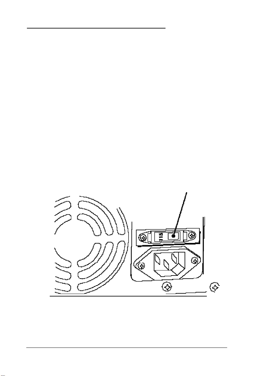
Setting the Voltage Selector Switch
Your system is powered by a 230 watt power supply. The
power supply voltage is controlled by a voltage selector switch
on the computer’s back panel that may be set to 115 VAC or
230 VAC.
The computer is shipped with the voltage selector switch set
to 115 VAC. This setting is appropriate for line source voltages
between 100 and 120 VAC. This is generally the appropriate
setting if you will use the computer in North America or Japan.
If you plan to operate the computer in the United Kingdom or
Europe, you will almost certainly need to reset the voltage
selector switch to 230 VAC. Line source voltages between 200
and 240 VAC are acceptable with the switch set to 230 VAC.
If you need to change the voltage selector switch setting, refer
to the illustration below.
voltage selector switch
1-4 Setting Up Your System
Page 19

Caution
Before you turn on the power to your system, you must be
sure the voltage selector switch is set to the appropriate
setting for the electrical power source in your location or
you will seriously damage your system.
To change the voltage selector switch setting, insert the tip of a
ball-point pen or a similar tool into the dimple on the switch.
Then slide the switch to the right to select 115 VAC or to the
left to select 230 VAC.
Installing Optional Equipment
Before you set up and connect your system components, you
may want to install any optional equipment you plan to use.
Chapters 6 and 7 give complete instructions for installing
options such as disk drives, memory modules, and option
cards.
Note
You may want to list the serial numbers and other important
information about the options you install in the “Equipment
Log” on page 1-11.
Note that the order in which you install option cards depends
on the type of cards you have. If you will be installing only ISA
option cards that did not come with their own configuration
(CFG) files, you should install the cards before you connect your
peripheral devices. Follow the instructions in your ISA card
manual to set the card’s switches or jumpers for your system.
You should also install any EISA cards before you connect
peripheral devices so your EISA Configuration utility can
automatically detect the cards and configure them correctly.
Setting Up Your System 1-5
Page 20
If you plan to install any ISA cards that came with their own
CFG files, you should install the cards after you have connected
the necessary peripheral devices and run the computer’s EISA
Configuration utility. This allows you to add the CFG file
information to your configuration so the program can give you
the card’s correct jumper and switch settings. Then you can set
the switches and jumpers and install the card. See the
documentation that came with your card(s) for information.
Be sure that the option card(s) you install do not exceed your
computer’s power supply limits, as described in Appendix B.
Then follow the instructions in Chapter 6 to install the cards.
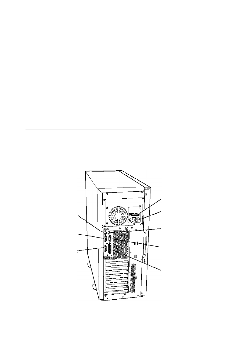
Connecting Peripheral Devices
Refer to the illustration below to locate the ports on the back of
your computer.
voltage
selector switch
1-6
keyboard port
serial port 2
VGA port
Setting Up Your System
AC inlet
mouse port
serial port 1
parallel port
Page 21

Before connecting the peripheral devices, make sure the power
buttons or switches on the computer and all peripheral devices
are turned off. Then follow these steps to connect the
peripheral devices:
1.
If necessary, insert the mouse cable connector into the
mouse port on the back panel.
Although the keyboard and mouse ports appear to be
identical, you cannot use them interchangeably. Be sure
to plug the keyboard and mouse into the correct ports.
2.
Insert the keyboard cable connector into the keyboard port
on the back panel.
3.
Connect the interface cables of any other peripheral devices
such as a monitor, printer, or modem to the appropriate
ports on the back panel.
4.
Connect the power cords for any peripheral devices to
grounded electrical outlets.
5.
Plug one end of the computer’s power cord into the AC inlet
on the back panel.
6.
Plug the other end of the computer’s power cord into an
appropriate electrical outlet.
Be sure to read the next section before you turn on the system.
Setting Up Your System 1-7
Page 22

Turning On the System
Read the following safety rules to avoid damaging the
computer or injuring yourself
Do not connect any power or peripheral device cables
when the computer’s power is on.
Never turn on the computer while a protective card is in a
5.25-inch diskette drive.
Never turn on the computer when its cover is off.
Never turn off or reset your computer while a disk drive
light is on. This can destroy data stored on the disk.
Always wait at least five seconds after you turn off the
power before you turn it on again. This prevents possible
damage to the computer’s electrical circuitry.
Do not leave a beverage near your system or any of its
components. Spilled liquid can damage the circuitry of
your equipment.
Always turn off the power and wait 30 seconds before you
disconnect the computer’s power cord and device cables,
and remove the cover. Only remove the cover to access
internal devices.
Never press the computer’s power, reset, or keyboard/
mouse lock buttons while the front panel is off.
1-8 Setting Up Your System
Page 23
Follow these steps to turn on the system:
1.
Make sure all peripheral devices, such as the mouse,
keyboard, and monitor, have been connected.
2.
Turn on the monitor and any other peripheral devices.
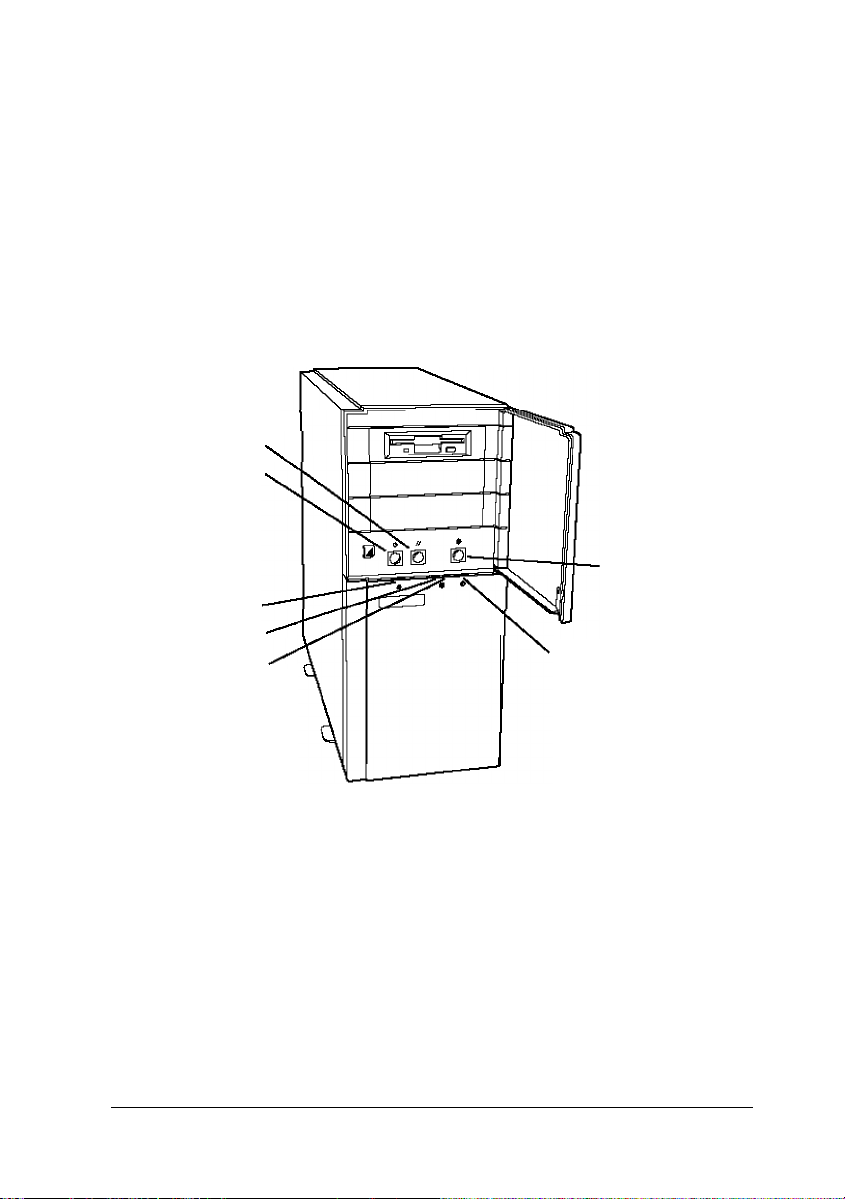
3.
Turn on your system by pressing the power button on the
front panel.
reset
button
power
button
power
indicator
IDE/SCSl drive
indicator
SCSI drive
indicator
4.
Verify that the power indicator light on the front panel is
keyboard/mouse
lock button
keyboard/mouse
lock indicator
on.
You are now ready to begin using your computer. See the next
section for information on configuring your system.
Setting Up Your System 1-9
Page 24

Configuring Your System
There are two programs you can use to configure your
computer: the SETUP program and the EISA Configuration
utility. Which one you use depends on the option cards you
may have installed in your computer.
You use the SETUP program to configure your computer only
in the following situations:
0
You did not install any option cards or installed only ISA
option cards that did not come with configuration (CFG)
files
0
You are not going to use the built-in SCSI subsystem
0
You do not have a diskette drive or have disabled your
diskette drive.
In all other cases, run the EISA Configuration utility to
configure your system.
Your computer’s SETUP program is stored in the system BIOS
ROM. You can run SETUP whenever you turn on or reset the
computer, regardless of whether you have installed an
operating system. See Chapter 2 for instructions on running the
program.
The EISA Configuration utility is on the System Configuration
diskette. See Chapter 3 for instructions on running this utility.
1-10 Setting Up Your System
Page 25

Equipment Log
Use this space to record information about your system. You
can refer to this section if you call for assistance.
Computer serial number:
Purchase location:
date:
Monitorserial number:
Printerserial number:
Other device serial number:
Other device serial number:
Other device serial number:
Other device serial number:
Option cardsinstalled:
Slot 1:
Slot 2:
Slot 3:
Slot 4:
Slot 5:
Slot 6:
Slot 7:
Slot 8:
Setting Up Your System
1-11
Page 26

IDE drives installed:
Bay 1:
Bay 2:
SCSI drives installed:
Bay 1:
Bay 2:
Bay 3:
Bay 4:
Bay 5:
Bay 6:
Other drives installed (diskette, tape, CD-ROM, etc.):
Bay 1:
Bay 2:
Bay 3:
Operating system version number:
Operating system serial number:
Software program
1-12 Setting Up Your System
Version number
Serial number
Page 27

Chapter 2
Running the SETUP Program
The SETUP program allows you to configure your computer
and set many different system options. Use SETUP to configure
your computer only in the following situations:
0
You did not install any option cards or installed only ISA
option cards that did not come with configuration (CFG)
files
0
You are not going to use the built-in SCSI subsystem
0
You do not have a diskette drive or have disabled your
diskette drive.
In all other cases, use the EISA Configuration utility instead of
the SETUP program to configure your system. See Chapter 3
for instructions on running the EISA Configuration utility.
Note
If you plan to operate your computer without a monitor,
keyboard, or diskette drive, see “Using Special
Configurations” in Chapter 4 before running SETUP or
the EISA Configuration utility. If you’ll be redirecting your
computer’s input and output to a serial port, be sure to see
“Operating Your Computer from a Remote Location” in
Chapter 4 before configuring your system.
Running the SETUP Program 2-1
Page 28

Your computer’s SETUP program is stored in the system BIOS
ROM. You can run SETUP whenever you turn on or reset the
computer, regardless of whether you have installed an
operating system.
Note
Any settings you make using the EISA Configuration utility
override those you set using SETUP.
Starting the Program
Follow these steps to run SETUP:
1.
Turn on the computer or press the reset button. You see the
memory counts for the memory test and then the power-on
diagnostic tests. You may also see this prompt:
Press Spacebar to Abort Memory Test
If you want to skip the memory test to shorten the time it
takes to enter SETUP, press the spacebar.
(If you press
perform the memory test.)
2.
If the power-on diagnostic tests do not find errors, you hear
a tone code and may see the following prompt:
To continue press: . . . . . . . SPACEBAR
To configure system press: . . . F1
The prompt remains on the screen for four seconds.
Press
F1 to run SETUP.
2-2 Running the SETUP Program
Ctrl Alt Del to reset the computer, it does not
Page 29

Note
If you ran SETUP previously and disabled the memory
test prompt or the SETUP prompt, you will not see these
messages. However, you can still press the spacebar to
skip the memory test or press F1 to start SETUP.
If the tests find a minor error or you have not yet installed
your operating system, the computer beeps twice; then you
see an error message and the following prompt:
To continue press: . . . . . . . SPACEBAR
To configure system press: . . . F1
To continue without running SETUP, press the spacebar.
To run SETUP, press F1.
If the power-on diagnostic tests find a serious error, you
hear a tone code indicating the error and the system halts
See Appendix A for a list of the error tone codes and
suggested solutions to the problem.
First you see an information screen that tells you when you
need to run SETUP instead of the EISA Configuration
utility. Press F1 to continue.
Now you see the first of four pages of SETUP information
Follow the instructions in the next section to view or
change your settings.
Running the SETUP Program 2-3
Page 30

Selecting Options
Use the keys listed in the table below to select SETUP program
options.
Setup key functions
key
Page Down or Display the next or previous page of SETUP information
Page Up
+tdf
+or-
E
SC
F5
Function
Move the cursorfrom the current option to the next or
previousavailable option
Change the setting of the currently highlighted option; if
the setting is a numeric value, + selects higher value sand
-
selects lower values
Displays the SETUP exit screen containing information
about the keys you can press to set default settings, exit
SETUP without saving settings, or save settings and exit
Sets all SETUP options to their default settings, except for
the system time and date
Selecting Settings
The table below lists the settings available for each SETUP
option and describes how they affect your configuration. The
numbers in parentheses refer to notes at the end of the table.
When you finish changing your settings, see “Exiting SETUP”
on page 2-16.
SETUP program options
Option
Time
Settings
hh:mm:ss Set the current hour(hh), minutes
2-4 Running the SETUP Program
Description
(mm), and seconds (ss); seconds
can only be reset to 0
Page 31

SETUP program options (continued)
Option
Date dd month yyyy
Onboard
Floppy
Diskette A
Diskette B
Onboard IDE Enabled Set to Enabled to use the built-in
Hard Drive 1
Hard Drive 2
Settings
Enabled*
Disabled
5.25”, 360 KB
5.25”, 1.2 MB
3.5”, 720 KB
3.5”, 1.44 MB (A*)
3.5”, 2.88 MB
Not Installed (B*)
Disabled* IDE hard disk drive controllerto
Type nn
Not Installed*
Description
Set the current day (dd), month,
and year (yyyy); automatically
tracksleap years
Set to Enabled to use the built-in
diskette drive controller; set to
Disabled to disable the built-in
controller if you are eithernot
using a diskette drive or will use a
controlleron an option card
Set to the type(s) of diskette
drive(s) installed in the system; set
to Not Installed if you do not
have the specified drive installed
control your IDE drive(s); set to
Disabled to use the IDE interrupt
(IRQ14) for an option card or if
you install an external IDE drive
controller (1)
Set to the hard disk drive type of
the specified IDE hard disk drive
or enter parameters for
user-definable drive type
according to the drive’s
documentation; select the
user-defined drive type number
you want to use in User Definable
Drivesoption, described below;
select Not Installed for both
options if you have installed a
SCSI hard disk drive. (For more
information, see “Hard Disk Drive
Types” on page 2-13.)
Running the SETUP Program 2-5
Page 32

SETUP program options (continued)
Option
Onboard SCSI Disabled*
SCSI BIOS
Mapping
User Definable 2 and 3*
Drives 48 and 49
Settings
H/W/ Only
Enabled
C0000H*
C8000H
EC000H
Description
Select Disabled if you are not
using the built-in SCSI controller
to free up interrupt IRQ11; select
H/W Only if you will not boot your
system from a SCSI device
connected to the built-in SCSI
controller; select Enabled if you
will boot from a SCSI device
connected to the built-in SCSI
controller (2)
If you enabled the Onboard SCSI
option, you must ensure that the
SCSI BIOS location does not
conflict with the onboard video
BIOS location; set this option to a
different starting addressthan
the Onboard Video BIOS
Mapping option address,
described on page 2-12
Select the pair of user-definable
drive types you want to use to
enter your drive’s parameters;
select the type and enter the
parametersusing the Hard Drive
option described above; note
that you configure drives 2 and 3
using the EISA Configuration
utility only
Video Type VGA/EGA*
CGA40
CGA80
MDA
Not Installed
640 x 480 Mode
Refresh Rate (4)
60 Hz*
75 Hz
x2, x16 @ 72 Hz
(72 Hz in 2 and 16
color modes only)
2-6 Running the SETUP Program
Select the type of adapter you
installed; if you are using the
built-in adapter, select VGA/EGA
(3)
Select the refresh rate
(frequency in Hertz) of the built-in
video controllerwhen it is
operating in 640 x 480 mode; see
your monitor manual to
determine the refresh rate your
monitor is capable of displaying
Page 33

SETUP program options (continued)
Option
800 x 600 Mode
Refresh Rate
1024 x 768
Mode Refresh
Rate
Video Font
OnBoard
Video
Controller
Settings
56 Hz*
60 Hz
72 Hz
Interlaced @
44/88 Hz
Non-Interlaced @
60 Hz
Non-Interlaced @
70 Hz
Non-Interlaced @
72 Hz
8 x 16
9 x 16*
Primary*
Secondary
Description
Select the refresh rate frequency
(in Hertz) of the built-in video
controllerwhen it isoperating in
800 x 600 mode; see your
monitor manual to determine the
refresh rate your monitor is
capable of displaying
Select the refresh rate frequency
(in Hertz) of the built-in video
controllerwhen it isoperating in
1024 x 768 mode; see your
monitor manual to determine the
correct refresh rate your monitor
is capable of displaying
Select the font dimensions of the
video characters that appear on
the screen; select 9 x 16 for use
with VGA and most programs
Set to Primary if you are using the
built-in video controller as your
primary display adapter; set to
Secondary to use the built-in
controller as the secondary
controller; if you install a VGA
display adapter card, the
computer may automatically
change the card to the primary
adapterand set the built-in
adapterto Secondary; all BIOS
video writesare directed to the
primary video display
Offboard
VGA/EGA
Adapter
Installed
Yes*
No
Set to Yes if you installed a video
display adapteron an option
card that contains a BlOSat
address C0000h; select No if you
have not installed a video option
card (5)
Running the SETUP Program 2-7
Page 34

SETUP program options (continued)
Option
Keyboard
Numlock on Yes
at boot No*
Password
Keyboard Disabled*
security hot key
(ClRL-ALT)
Settings
Installed
Not Installed*
Not installed*
Installed
Description
Set to Installed to allow your
computer to operate with a
keyboard; set to Not Installed to
use your computer without a
keyboard (for example, as a
network server) and allow
power-on diagnostic tests to
report a disabled keyboard
instead of a failed keyboard
Set to Yes to turn on Num Lock
mode wheneveryou turn on or
reset yourcomputer; set to No to
turn it off
To set a power-on password,
highlight thisoption when the
setting is Not installed and press
+or-. Then follow the instructions
on the screen to enter the
password; the setting changesto
Installed. (See Chapter 4 for
more information about the
password function.)
Thisoption has no effect on your
system
POST Memory Enabled*
Test Prompt Disabled
2-8 Running the SETUP Program
Set to Enabled to display the skip
memory test prompt when you
turn on or reset yourcomputer;
select Disabled to prevent
display of the prompt. (You can
still press the space bar to skip the
test if you disabled the prompt.)
See page 2-2 for more
information.
Page 35

SETUP program options (continued)
Option
POST Setup
Prompt Disabled
Boot Device Diskette or Hard
Base Memory
Extended
Memory
Settings
Enabled*
Drive *
Hard Drive Only
640 KB*
512 KB
[memory size]
Description
Set to Enabled to display the
prompt to run the SETUP program
when you turn on or reset your
computer; select Disabled to
prevent display of the prompt.
(You can still press F1 to run
SETUP if you disable the prompt.)
See page 2-2 for more
information.
Select the device(s) from which
you want to be able to boot your
system; the setting isignored if
the diskette drive iscontrolled by
a controlleron an option card
Displays the size of the base
memory; setting is 640 KB unless
there is a base memory failure or
you reassigned the base memory
between 512 KB and 640 KB in the
Base Memory option described
below
Displays the amount of extended
memory above 1MB, including
memory installed on SIMMs and
any memory option cards you
cannot change this setting
Base Memory Enabled*
Above 512K Disabled
Speaker Enabled*
Disabled
Set to Enabled to assign the base
memory addressfrom 512 KB to
640 KB to memory on the system
board; set to Disabled if you
install an option card that
reserves these addresses for its
own use
Set to Enabled to turn on the
computer’s built-in speaker; set
to Disabled to turn off the
speaker (cannot be turned on
by application software if
Disabled)
Running the SETUP Program 2-9
Page 36

SETUP program options (continued)
Option
LCD
Onboard Enabled*
Mouse Disabled
Parallel Port Address 378H:
Serial Port 1 (6) Address 3F8H/IRQ4*
Settings
Enabled*
Disabled
Compatible / IRQ7*
Address 278H:
Compatible / IRQ7
Address 378H:
Bidirectional / IRQ7
Address 278H:
Bidirectional / IRQ7
Disabled
Address 2F8H/IRQ3
Address 3E8H/IRQ10
Disabled
Description
Set thisoption to Disabled; your
system does not have an LCD
screen
Set to Enabled if you have
connected a mouse to the
built-in mouse port; set to
Disabled if you are not using a
mouse (freeshardware interrupt
IRQ12) or if you are using a
mouse controller installed on an
option card
Select one of the Compatible
optionsto set the port for IBM AT
compatible signals select one of
the Bidirectional optionsto set
the port for IBM PS/2 compatible
bidirectional signals; address
378H is for LPT1 and 278H is for
LPT2; select Disabled to prevent
the port from reacting to any
signaIs (no resourcesare
allocated when Disabled)
Select the addressyou want to
use for serial port 1; address 3F8H
is for COM1, 2F8H is for COM2,
and 3E8H is for COM3; set to
Disabled to prevent the port
from reacting to any signaIs (no
resourcesare allocated when
Disabled)
Serial Port 2 (6) Address 2F8H/IRQ3*
Address 3E8H/IRQ10
Address 2E8H/IRQ11
Disabled
2-10 Running the SETUP Program
Select the addressyou want to
use for serial port 2; address 2F8H
is for COM2, 3E8H is for COM3,
and 2E8H is for COM4; set to
Disabled to prevent the port
from reacting to any signals (no
resourcesare allocated when
Disabled)
Page 37

SETUP program options (continued)
Option
Console Disabled* Set to Disabled to prevent
Redirection to
COM1 2400 Baud input and output to serial port 1;
Console Disabled* Set to Disabled to prevent
Redirection to 1200 Baud redirection of the computer’s
COM2 2400 Baud input and output to the serial
CPU Speed
Cache Write Through
Settings Description
1200 Baud
9600 Baud set to the speed the computer
9600 Baud port assigned as COM2; set to
Fast*
Slow
Write Back
Disabled*
redirection of the computer’s
should use to copy the
redirected input/output to serial
port 1
the speed the computershould
use to copy the redirected
input/output to the port
Select Fast to set the computer’s
processor to operate at its
maximum speed; select Slow to
set the processor to operate at a
simulated 8 MHz speed to
accommodate old application
programsthat may require it;
slow speed also disablesany
system caching
Set to Write Through to enable
internal and external caching on
the 486DX2/66 CPU card; set to
Write Back to enable internal
and external caching on any of
the single-or dual-Pentium CPU
cards set to Disabled to prevent
caching when you are using
time-dependent software
I/O Recovery Standard Select Enhanced to set a fast I/O
Time
Enhanced* recovery time; set to Standard if
you have trouble with an
application program or option
card that is running in enhanced
mode
Running the SETUP Program 2-11
Page 38

SETUP program options (continued)
Option
Posted I/O
Writes (7)
Concurrent Enabled*
Refresh
Onboard
Video BIOS
Mapping
Shadow Disabled*
C0000 to C7FFF Enabled
C8000 to CFFFF
E0000 to E7FFF
Scan FLASH
User Area
Settings
Standard*
Fast
Disabled
Disabled
To E0000H*
To C0000H
Enabled
Disabled*
Description
Set to Standard to improve
performance by posting memory
and I/O writes to the ElSA bus set
to Disabled if any of your option
cards do not support this feature
Set to Enabled to improve
performance by executing
concurrent CPU cache and
main memory refresh cycles; set
to Disabled if you have trouble
with any application programs
while this option is enabled
Select To E0000H to map the
onboard video BIOS to memory
address E0000h; select To C0000H
to map the video BlOS to
address C0000h to provide
compatibility with old
application software (8)
Set any of these optionsto
enable ordisable shadowing of
ROM data from the indicated
memory addressrange (8)
Set to Enabled to allow the BIOS
to call any code you have
installed in the 8KB block EA000h
to EBFFFh prior to booting the
computer (FLASH user area); set
to Disabled to scan the block
normally
Multiprocessor Enabled
APIC
* Default setting
1
If you will boot your system from a SCSI hard disk drive, you must disable
the built-in IDE controller and set both hard disk drive types to Not
Installed.
2-12 Running the SETUP Program
Disabled*
Set to Enabled if you installed the
dual-Pentium CPU card; set to
Disabled for any single processor
CPU card
Page 39

2
You must also run the EISA Configuration utility to fully enable yourbuilt-in
SCSl controller.
3
When you select Not Installed for the Video Type option, the display type
bits are configured for VGA.
4
If you change the refresh rate, you must press the reset button or turn
the computer off and then on again aftersaving your settings to reset the
rate.
5
The Offboard VGA/EGA Adapter Installed option settings do not affect
yourbuilt-in video controller. To enable ordisable thiscontroller, you must
set jumper E0290, See Chapter 6 for more information.
6
You cannot set Serial Port 1 and 2 to the same address. If you attempt to
do so, you see an error message.
7 The following I/O address ranges are never posted: 0000h to 00FFh, 0400h
to 04FFh, 0800h to 08FFh, and 0C00h to 0CFFh.
8
If you set the Onboard Video BIOS Mapping option to To C0000H, you
must set the Shadow C0000 to C7FFF option to Disabled to avoid a
memory conflict. If you set the Onboard Video BlOS Mapping option to
To E0000H, you must set the Shadow E0000 to E7FFF option to Disabled to
avoid a conflict. You must also set the SCSI BlOSMapping option so that
the SCSI BlOS does not conflict with any of these addresses.
Hard Disk Drive Types
The following table lists the types of IDE hard disk drives you
can use in your computer. Check this table and the manual that
came with your hard disk to find the correct type for the hard
disk drive(s) installed in your computer.
If the documentation for your hard disk drive includes only
the drive parameters and not a specific type number, search
through this list to find a type that matches your drive. If
none of the types match, select the user-defined drive types,
48 and 49, and set your own parameters using the Hard Drive n
option. See page 2-5. (You can configure user-defined drive
types 2 and 3 with the EISA Configuration utility only.)
Running the SETUP Program 2-13
Page 40

Note
Be sure you enter the correct drive type or parameters for
your drive; if they are incorrect, the computer will not
recognize your drive.
Hard disk drive types
22 873
23 636
*
User-definable using EISA Configuration utility only
13 -1
16 -1
2-14 Running the SETUP Program
873 36 199MB
637 63
313MB
Page 41

Hard disk drive types (continued)
Running the SETUP Program 2-15
Page 42

Exiting SETUP
To exit the SETUP program, press ESC at any of the SETUP
pages and follow the instructions on the screen to do any of the
following:
0
To continue running SETUP, press ESC again.
0
To save your settings and then exit and reboot the
computer, press F4.
0
To load default settings for all the SETUP options, press F5;
the program erases any changes you have made (except for
the time and date).
0
To exit SETUP without saving your settings, press F6.
2-16 Running the SETUP Program
Page 43

Chapter 3
Running the EISA Configuration Utility
The EISA Configuration utility provided with your system
allows you to configure your computer when you have done or
will do the following:
0
Installed EISA option cards
0
Installed ISA option cards that came with configuration files
0
Plan to use the built-in SCSI controller.
You can use the EISA Configuration utility to do the following:
Learn about the configuration process
Set the date and time
Copy the configuration files for any option cards you install
Configure the system board and any option cards
Create one or more System Configuration Information
(SCI) files
Access other system utilities, such as password, CPU speed,
and cache utilities.
Note
If you plan to operate your computer without a monitor,
keyboard, or diskette drive, see “Using Special
Configurations” in Chapter 4 before running the EISA
Configuration utility. If you’ll be redirecting your
computer’s input and output to a serial port, be sure to see
“Operating Your Computer from a Remote Location” in
Chapter 4 before configuring your system.
Running the EISA Configuration Utility
3-1
Page 44

You need to run the EISA Configuration utility to configure
your system with your EISA option cards installed before you
use your computer. You may need to run it again later if you
add or remove options, such as memory, disk drives, or option
cards.
After running the utility, you save the current configuration in
the computer’s CMOS RAM and in a file called SYSTEM.SCI.
Your computer checks this information each time you turn it
on and assigns system resources based on the configuration
options you selected.
Once you configure your computer with this utility, you should
not use the SETUP program in your computer’s BIOS. Always
use the EISA Configuration utility to configure your computer.
If you want to create an alternate configuration for your
computer or another computer, you can create an alternate SCI
file. See page 3-29 for more information.
Note
The first time you configure your computer, you must run
the program from the System Configuration diskette and it
is best to always run it from there. However, you can run the
EISA Configuration utility from your hard disk to speed up
its performance. See page 3-36 for information on copying
the files to your hard disk. Then see page 3-31 for
instructions on running the utility from a command line.
3-2 Running the EISA Configuration Utility
Page 45

How to Use This Chapter
This chapter is divided into the following four sections:
The Configuration Process describes the various aspects of
configuring your computer with the EISA Configuration
utility. It also tells you how to use the keyboard or a mouse
with the program and how to use on-line help.
Configuring Your System provides step-by-step
instructions for running the EISA Configuration utility and
is organized in the order in which you should perform the
operations.
Using Alternate Configuration Files explains how to
create and use alternate configuration files, if this is
necessary.
Using Special Modes tells you how to configure your
computer by running it in special operating modes, such as
non-target modeling mode.
Read “The Configuration Process” first to familiarize yourself
with all aspects of the configuration process. Then perform the
configuration operations in the order they are described under
“Configuring Your System.”
If you need to create alternate configuration files or run the
program in special modes, see pages 3-29 or 3-31, respectively.
Running the EISA Configuration Utility 3-3
Page 46

The Configuration Process
This section describes the following configuration operations:
0
Using the configuration files
0
Using the keyboard or a mouse with the program
0
Using on-line help
Using Configuration
Configuration (or CFG) files provide information to the system
about a card’s functions and resource requirements so your
computer can allocate its resources efficiently. They also
provide instructions for setting any switches and jumpers on
ISA cards.
You can copy a configuration file for each card you install
to your System Configuration diskette using the EISA
Configuration utility. EISA cards come with the necessary CFG
file to allow the program to configure the card automatically.
See your EISA card documentation for more information.
ISA option cards may come with the necessary CFG file for
this program. If you do not have a CFG file for your ISA card,
you can still install the card in your system. However, you
should configure the rest of your system and then follow the
instructions that came with the card to set any of its switches
or jumpers.
Files
3-4 Running the EISA Configuration Utility
Page 47

Using the Keyboard
If you use a keyboard when you run the EISA Configuration
utility, refer to the table below for a description of the keys you
can use to move the cursor and select items. If you’ll be using a
mouse with the program, see “Using a Mouse” below. Most of
the screens show which keys you can press to perform various
operations. Follow the instructions on each screen.
Whenever the <OK> icon is highlighted, press Enter to select
<OK>. To select <Cancel>, you can either press the ESC key or
highlight
Key commands
<cancel>
and press Enter.
Key
Tabor&
Shift Tab
tor4
Enter
E
SC
Page Up or Page Down
Ctrl Home
Ctrl End
or?
Function
Moves the cursor to the next field
Moves the cursor to the previousfield
Highlights items with in a list or scrolls the
screen
Selects the highlighted option
Cancelsthe current action or menu
Moves the cursor up or down one screen
Moves the cursor to the first line of
information
Moves the cursor to the last line of
information
Using a Mouse
The first time you run the EISA Configuration utility, you must
use the keyboard. After configuring your system, load your
operating system and then install your mouse driver. Then you
can run the utility using your mouse.
Running the EISA Configuration Utility 3-5
Page 48

To select most options, place the cursor on the option, click
once to highlight it, and again to select it.
When you see
text. Place the cursor on the arrow indicating the scroll
direction and hold down the mouse button. Release it to stop.
Keep in mind that this chapter gives keyboard instructions
when describing how to use the EISA Configuration utility.
You should substitute the appropriate mouse equivalents when
performing the same operations.
‘/‘or &
on the side of a screen, you can scroll the
Using On-line Help
The EISA Configuration utility provides extensive on-line help
information. You can obtain help in the following ways:
0
Highlight a menu option to see a description of its function.
0
Select Step 1:
information for detailed information about each step in
the configuration process.
0
Press the F1 key whenever you see Help=F1. The
following menu appears:
EISA Configuration Help
Important EISA configuration
3-6
Current screen
Selected item or board
All boards
Keys
Topics
Using help
EISA configuration
Press & to highlight the help information you need; then
press Enter to select it.
Running the EISA Configuration Utility
Page 49

Configuring Your System
Follow the instructions in this section and on your screen to
configure your computer using the EISA Configuration utility
Configure your system in the following order:
Set the date and time
When you add an option card, select the Add or remove
boards option to copy the necessary configuration files
Use the view or edit the details of your
configuration option to define your configuration
View or print your jumper and switch settings
Save the configuration as you exit the program.
Starting the Program
Follow these steps to start the EISA Configuration utility:
1.
Insert the System Configuration diskette in drive A and turn
on or reset the computer.
2.
After a moment, you see the title screen for the EISA
Configuration utility. Press Enter to continue. You see the
Welcome screen.
Note
If you installed any EISA option cards in your system,
you see a message telling you to configure your
computer. Press Enter to continue.
Running the EISA Configuration Utility
3-7
Page 50

3.
Press Enter. You see the Main Menu:
Main Menu
Learn about configuring your computer
Configure computer
Set date
Set time
Access System Utilities
Maintain system configuration diskette
Exit from this utility
4.
For an overview of the configuration process, highlight
Learn about configuring your computerand
press Enter. When you have finished reading the three
Help screens, press Enter to return to the Main Menu.
(You can press F10 to return to the Main Menu at any
time.)
Now set the date and time of your computer’s real-time clock,
as described below.
Setting the Date and Time
The real-time clock in your computer continuously tracks the
date and time-even when the computer is turned off. The first
time you run the configuration program, set the date and time
for your computer. You can set them again later to adjust your
clock for seasonal time adjustments, such as daylight savings
time. The computer automatically changes the date for leap
years.
3-8 Running the EISA Configuration Utility
Page 51

Follow these steps to set the date and time:
1.
At the Main Menu, select Set date. You see a prompt such
as the following:
Date 12-12-1994 (mm-dd-yyyy)
2.
The current setting for Date is highlighted. Correct it as
necessary. You can use the arrow keys to move the cursor
and overtype the date. Then press Enter.
3.
At the Main Menu, select Set time. You see a prompt
similar to the date prompt.
4.
You can use the arrow keys to move the cursor and overtype
the time. Then press Enter. You see the Main Menu.
Now you can configure your computer, as described below.
Performing the Configuration Steps
Follow these steps to configure your computer:
1.
At the Main Menu, select Configure computer. After a
moment, you see this menu:
Steps in configuring your computer
Step 1: Important EISA
configuration information
Step 2: Add or remove boards
Step 3: View or edit details
Step 4:
Step 5: Save and exit
Examine required switches
Running the EISA Configuration Utility
3-9
Page 52

Note
If you installed EISA option cards in your system, the
program first asks you to insert a diskette containing
a CFG file for the EISA card. Remove the System
Configuration diskette, insert the appropriate
configuration diskette, and press Enter. Follow the
instructions on the screen to complete the installation
and then go to the next step.
2.
Select Step 1 and read the information displayed on your
screen about configuring your system. If you want to print
any of the screens to the printer connected to port LPT1,
press the Print Screen key.
3.
Select Step 2 and follow the instructions on the screen to
add, remove, or move option cards in your configuration
and copy any necessary CFG files to your System
Configuration diskette. See the next section for more
information.
4.
Select Step 3 and follow the instructions on the screen to
view or edit the details of your system board and your
option cards. See “Defining the Configuration Settings”
below for more information.
5.
Select Step 4 if you want to view or print the current
configuration and any switch or jumper settings you may
need to change. Follow the instructions on the screen.
6.
When you finish configuring your system, select Step 5
to save the configuration in your computer’s CMOS RAM
and reboot the system. You can also exit the program
without saving the configuration, if necessary. Follow the
instructions on the screen.
3-10 Running the EISA Configuration Utility
Page 53

Adding or Removing a Board
Select
Step 2:
to add or remove an option card. The program displays a list
of the computer’s slots with a description of any cards that it
detects. The computer automatically detects EISA cards, but
you must add the necessary ISA card information. Follow the
instructions on the screen to add, move, or remove an option
card.
When you add an option card, you need the configuration
diskette that came with the card. Follow the instructions on the
screen to copy the appropriate CFG files to your System
Configuration diskette.
Note
Your computer does not come with a CFG file library
diskette. When adding a card, insert the CFG file diskette
that came with the card. If you are installing an ISA card that
did not come with a diskette, follow the instructions in the
card’s documentation to set the appropriate jumpers.
Add or remove boards when you need
Defining the Configuration Settings
Select
Step 3:
configuration menu to view your system configuration options.
Then follow the instructions on the screen to edit the settings of
these options. You can also perform various advanced
configuration operations by accessing the Advanced menu. See
“Using the Advanced Configuration Options,” later in the
chapter, for more information.
You cannot change the settings for certain options because they
are detected and set automatically by the program. Some
options or settings may not be available, depending on the type
of microprocessor installed in your computer.
View or edit details from the
Running the EISA Configuration Utility 3-11
Page 54

If you add any EISA option cards to your system, various
configuration options for the card(s) appear on the screen
following the system board options. See your EISA option card
documentation for information about configuring your card(s).
The table below describes the settings available for each of the
system board options. The numbers in parentheses refer to
notes at the end of the table.
System board options
Option
System
Processor
Module
System Board [memory size] Displays the amount of
Extended Extended Memory extended memory in the
Memory system including memory
System Base
Memory Option 512KB Base Memory
User Definable Types 2 and 3* Select the pair of userHard Drives Types 48 and 49 definable drive types you
Settings
[processor type]
640KB Base Memory* Select 640KB to use all of this
Description
Displays the type of processor
module installed in yours system
installed on SIMMs and any
memory option cards you
cannot change this setting
memory as base memory;
select 512KB to reassign the
memory addresses from 512KB
to 640KB if you install an option
card that uses these
addresses
want to use; select the type
and enter the parametersat
the appropriate Hard Drive n
option(s) described below
3-12 Running the EISA Configuration Utility
Page 55

System board options (continued)
Option
Cache Control Cache Enabled-
Onboard
Floppy
Controller
Diskette A 35 inch 1.44MB drive*
Settings
Write Through Mode
Cache Enabled-
Write Back Mode
Cache Disabled*
Enabled*
Disabled
3.5 inch 720KB drive
3.5 inch 2.88MB drive
5.25 inch 1.2MB drive
5.25 inch 360KB drive
Diskette A Disabled
Description
Set to Enabled-Write Through
Mode to enable caching on
the 486DX2/66 CPU card; set
to Enabled-Write Back Mode
to enable caching on any of
the single or dual-Pentium
CPU cards set to Disabled to
prevent caching when you
are using time-dependent
software. You can also turn
cache control off and on
using the EISA System Utilities;
see Chapter 4.
Set to Enabled to use the
built-in diskette drive
controller; set to Disabled to
disable the built-in controller
and use a controlleron an
option card
Set to the type of diskette
drive installed as drive A in
yours system; set to Diskette A
Disabled if you have removed
yourdiskette drive
Diskette B 3.5 inch 1.44MB drive
3.5 inch 720KB drive
3.5 inch 2.88M B drive
5.25 inch 1.2MB drive
5.25 inch 360KB drive
Diskette B Disabled*
Onboard IDE Enabled
Hard Disk Disabled*
Controller
Running the EISA Configuration Utility 3-13
Set to the type of diskette
drive installed as drive B in
your system; set to Diskette B
Disabled if you did not install a
second diskette drive
Set to Enabled to use the
built-in IDE hard disk drive
controllerto control your IDE
drive(s); set to Disabled to use
an external IDE drive controller
or the built-in SCSI controller
(1)
Page 56

System board options (continued)
Option
Hard Drive 1
and
Hard Drive 2
Parallel Port Base Address 378h - Select one of the Compatible
Serial Port 1
Settings Description
Drive Type nn Set to the hard disk drive type
Hard Drive n Disabled* of the specified IDE hard disk
drive or set to user-definable
drive types (2, 3, 48, or 49) and
enter parameters according
to the drive’sdocumentation;
see “Hard Disk Drive Types’ on
page 3-25 (1)
Compatible* optionsto set the port for
Base Address 378h - IBM AT compatible signals
Bidirectional select one of the Bidirectional
Base Address 278h - optionsto set the port for
Compatible IBM PS/2 compatible
Base Address 278h - bidirectional signals; address
Bidirectional 378h is for LPT1 and 278h is for
Disabled LPT2; select Disabled to
prevent the port from reacting
to any signals (no resources
are allocated when Disabled)
Base address 03F8h* Select the addressyou want
Base address 02F8h to use for serial port 1; address
Base address 03E8h 03F8h is for COM1, 02F8h is for
Disabled COM2, and 03E8h is for
COM3; set to Disabled to
prevent the port from reacting
to any signals (no resources
are allocated when Disabled)
(2)
Serial Port 2 Base address 02F8h* Select the addressyou want
Base address 03E8h to use for serial port 2; address
Base address 02E8h 02F8h is for COM2, 03E8h is for
Disabled COM3, and 02E8h is for
COM4; set to Disabled to
prevent the port from reacting
to any signals (no resources
are allocated when Disabled)
(2)
3-14 Running the EISA Configuration Utility
Page 57

System board options (continued)
Option
COM1
Redirection
COM2
Redirection
Video Type VGA/ EGA*
Offboard No -Enable
VGA/ EGA Onboard Video
Video Adapter Controllervia
Settings
Disabled*
1200 Baud
2400 Baud
9600 Baud
Disabled*
1200 Baud
2400 Baud
9600 Baud
CGA -80 columns
CGA -40 columns
MDA
Not Installed
Jumper*
Yes-Disable
Onboard Video
Controllervia Jumper
Description
Set to Disabled to prevent
redirection of the computer’s
input and output to the serial
port assigned to COM1; set to
the speed the computer
should use to copy the
redirected input/output to the
serial port assigned to COM1
Set to Disabled to prevent
redirection of the computer’s
input and output to the serial
port assigned to COM2; set to
the speed the computer
should use to copy the
redirected input/output to the
serial port assigned to COM2
If you have installed a video
display adapteron an option
card, select the type of
adapteryou installed; if you
are using the built-in video
controller, select VGA/EGA
Set to Yes if you have installed
a video display adapter on an
option card that containsa
BlOS at address C0000h;
select No if you have not
installed a video option card;
make sure jumper E0290 is set
to match the setting you
select here
Onboard
Video
Controller
Primary*
Secondary
Set to Primary if you are using
the built-in video controlleras
yourprimary adapter; set to
Secondary if you are not using
your built-in controller. This
setting isignored if jumper
E0290 is set to disable the
built-in VGA controllerand
you set thisoption to Primary
Running the EISA Configuration Utility 3-15
Page 58

System board options (continued)
Option
Onboard
Video BIOS
Mapping Disabled
640 x 480
Mode Refresh
Rate (3)
800 x 600
Mode Refresh
Rate
Settings
To E0000h*
To C0000h
60 Hz*
75 Hz
x2, x16 @ 72 Hz
(72 Hz in the 2 and 16
color modes only)
56 Hz*
60 Hz
72 Hz
Description
Select To E0000h to map the
onboard video BIOS to
memory address E0000h;
select To C0000h to map the
video BIOS to address C0000h
forcompatibility with older
application software; this
option isautomatically set to
Disabled if you disable the
Onboard Video Controller
option, asdescribed above;
the video BIOS shadow
optionsare automatically set
to Enabled at eitheraddress
based on the setting selected
here
Select the refresh rate
frequency (in Hertz) of the
built-in video controllerwhen it
isoperating in 640 x 480
mode; see your monitor
manual to determine the
refresh rate your monitor is
capable of displaying
Select the refresh rate
frequency (in Hertz) of the
built-in video controllerwhen it
isoperating in 800 x 600
mode; see your monitor
manual to determine the
refresh rate your monitor is
capable of displaying
1024 x 768
Mode Refresh
Rate
Interlaced @
44/88 Hz
Non-Interlaced @
60 Hz
Non-Interlaced @
70 Hz
Non-Interlaced @
72 Hz
3-16 Running the EISA Configuration Utility
Select the refresh rate
frequency (in Hertz) of the
built-in video controllerwhen it
isoperating in 1024 x 768
mode; see your monitor
manual to determine the
refresh rate your monitor is
capable of displaying
Page 59

System board options (continued)
Option
Shadow Enabled Set to Enabled to shadow
C0000h - C7FFFh
C8000h - CFFFFh
E0000h - E7FFFh
Keyboard Enabled*
Control Disabled
Onboard Enabled* Set to Enabled if you have
Mouse Control Disabled connected a mouse to the
Speaker
Control
Settings Description
(E0000h - E7FFFh*)
Disabled memory addressrange in
(C0000h - C7FFFh
and C8000h - CFFFh*) data in ROM
Enabled*
Disabled
ROM data to the specified
RAM; set to Disabled to leave
Set to Enabled to allow your
computerto operate with a
keyboard; set to Disabled to
use your computer without a
keyboard (for example, as a
network server) and allow
power-on diagnostic test to
report a disabled keyboard
ratherthan a keyboard error
built-in mouse port; set to
Disabled if you are not using a
mouse (freeshardware
interrupt IRQ12) or if you are
using a mouse controller
installed on an option card
Set to Enabled to turn on the
computer’sbuilt-in speaker;
set to Disabled to turn off the
speaker (cannot be turned on
by application software if
Disabled)
CPU Speed
FAST
SLOW
Select FAST to set the
computer’s processor to
operate at itsmaximum
speed; select SLOW to set the
processor to operate at a
simulated 8 MHz speed to
accommodate old
application programsthat
may require it
Running the EISA Configuration Utility 3-17
Page 60

System board options (continued)
Option
NumLock Boot ON at Boot
State OFF at Boot*
I/O Recovery Standard
Time
Posted I/O
Writes
Concurrent Enabled*
Refresh
Settings
Enhanced*
Standard*
Fast
Disabled
Disabled
Description
Select ON at Boot to enable
Num Lock mode whenever
you turn on or reset your
computer; select OFF at Boot
to disable it
Select Enhanced to set fast
I/O recovery times; set to
Standard if you have trouble
with an application program
or option card that is running
in enhanced mode
Set to Standard to improve
performance by posting
memory and I/O writes to the
EISA bus set to Disabled if any
of your option cards do not
support thisfeature
Set to Enabled to improve
performance by executing
concurrent CPU, cache, and
main memory refresh cycles;
set to Disabled if you have
trouble with application
programswhile thisoption is
enabled
LCD Operation Enabled*
Disabled
Scan FLASH
User Area
Enabled
Disabled*
3-18 Running the EISA Configuration Utility
Set thisoption to Disabled;
your system does not have an
LCD screen
Set to Enabled to allow the
BlOS to call any code you
have installed in the 8KB block
EA000h to EBFFFh (FLASH user
area) prior to booting the
computer; set to Disabled to
scan the block normally
Page 61

System board options (continued)
Option
POST Memory Enabled *
Test Prompt Disabled
POST Setup
Control
Boot Device
Control
Reserved [settings vary]
System
Resources
Settings
Enabled -Prompt for
setup entry *
Enabled -Suppress
setup prompt
Setup Disabled
Boot from Diskette or
Hard Drive *
Boot from Hard Drive
Only
Description
Set to Enabled to display the
skip memory test prompt when
you turn on or reset your
computer; select Disabled to
prevent display of the prompt
(You can still press the spacebar to skip the test if you
disabled the prompt; see
Chapter 2)
Select Enabled -Prompt for
setup entry to display the
prompt to run the SETUP
program when you turn on or
reset the computer; select
Enabled -Suppress setup
prompt to prevent display of
the prompt; select Setup
Disabled to prevent entry into
the SETUP program until this
option is changed
Select the device(s) from
which you want to be able to
boot your system (4)
Press Enter and F6 to display
resources, such asinterrupts
and memory addressranges,
reserved for use by the system
board
* Default setting
1
To boot your system from a SCSI hard disk drive, you must disable the
built-in IDE controller and set both hard disk drive types to Disabled.
2
You cannot set Serial Port 1 and 2 to the same address. If you attempt to
do so, you see an error message.
3
If you change the refresh rate, you must press the reset button or turn the
computer off and on again aftersaving your settings to reset the rate.
4 The Boot Device Control setting is ignored if the diskette drive iscontrolled
by a SCSI option card.
Running the EISA Configuration Utility 3-19
Page 62

The options described in the table below appear on the View
or edit details screen only if you are running the EISA
Configuration utility in Advanced mode. See “Using Special
Modes” on page 3-31 for more information.
Advanced mode system board options
Option
Video Font Size
Extended
Memory Range
Definitions
Additional Enabled
expansion Disabled*
board address
space
EISA Enhanced Master Burst
Cycles
Settings
9x16*
8x16
[settings vary]
Description
Select the font dimensions of the
video charactersthat appear on
the screen; the 9 x 16 font size
should be used for most
application programs
Displays the defined ranges of
extended memory resident on
the system board and allowsyou
to customize them, though you
should let the ECU automatically
set them
If you have installed more than
15MB of memory in your system,
you may want to set thisoption
to Enabled to map additional
addressspace to the ElSA bus for
use by option cards. Enabling this
space opens a 1MB to 128KB
area between addresses
0F0000h and 0FE0000h and
reducesthe available extended
memory by 1MB. Select Disabled
to use this address area for
extended memory.
This option has no effect on your
system
3-20 Running the EISA Configuration Utility
Page 63

Advanced mode system board options (continued)
Option
Settings
Description
Slot
4 A
EN
Control
* Default setting
EISA Compatible*
ISA Compatible
When dot 4 is set to EISA
Compatible, it uses the ElSA
geographicaladdressing
scheme. If you set dot 4 to ISA
Compatible, it allowsall types of
I/O accesses that may be
required by option cards
addressed in the range 0-255.
The options described in the next two tables configure the
built-in SCSI controller and your SCSI devices.
Built-in SCSI controller options
Option
Enabled SCSI
Controller
Settings
Boot from SCSI, BIOS
Mapped to C0000h
Boot from SCSI, BIOS
Mapped to C8000h*
Boot from SCSI, BIOS
Mapped to E0000h
Boot from SCSI, BIOS
Mapped to EC000h
SCSI Hardware
Enabled - SCSI BIOS
Disabled
Disabled
Description
Select one of the Boot from
SCSI options to enable the
SCSI BIOS at the indicated
address and enable the
SCSI controller; select SCSI
Hardware Enabled -SCSI
BlOS Disabled when you
boot from a non - SCSI drive
to enable the SCSI
hardware but not load the
SCSI BIOS if you are not
using the built-in SCSI
sub system, select Disabled
Bus Release Time
60 BC LKS*
44 BC LKS
28 BC LC KS
12 BC LC KS
2 BC LC KS
This option sets the amount
of time the SCSI controller
continues to transfer data
afterbeing pre-empted by
a busmaster. The default
setting of 60 BC LC KS (bus
clocks) is usually sufficient. If
you install multiple bus
master option cards select
one of the faster settings to
free the ElSA bussooner.
Running the EISA Configuration Utility
3-21
Page 64

Built-in SCSI controller options (continued)
Option
Settings
Description
Data FIFO
Threshold
SCSI Channel 7*
A and B,
Host Adapter 5
SCSI ID
SCSI Channel Enabled*
A and B, Disabled
SCSI Bus Parity
Check
SCSI Channel 256 milliseconds
A and B, 128 milliseconds
SCSI Selection 64 milliseconds
Time
100%*
75%
50%
00%
6
4
3
2
1
0
32 milliseconds
This option sets the
percentage of data FIFO
used by the controller to
match SCSI and host
system data trader rates
The default setting of 100%
is usually sufficient.
Select the SCSI ID for the
indicated built-in SCSI
interface (host adapter);
normally you should assign
ID 7 to the host adapter, IDS
0 and 1 to SCSI hard disk
drives, and the other IDs to
other devices, if present.
Because channels A and B
are separate SCSI buses,
you can assign each host
adapter as lD 7
Select Enabled to generate
parity checking on the host
adapter; if an attached
SCSI device does not
support parity checking, set
this option to Disabled
This option sets the amount
of time the host adapter
uses to complete the SCSI
selection phase; fader
times speed up the SCSI bus
but all devices on the SCSI
bus must be compatible
with the speed you select
SCSI Channel Enabled*
A and B, Disabled
SCSI Bus Reset
at Power-on
3-22 Running the EISA Configuration Utility
Select Enabled to reset the
SCSI bus each time you turn
on or reset the computer;
this option should always
be set to Enabled
Page 65

Built-in SCSI controller options (continued)
Option
Settings
Description
Primary
Channel
Selection
* Default setting
A*
B
Selects the order the system
uses as it scans the SCSI
channelsat BIOS or driver
initialization
For the options described below, press Enter at the main option
to access the BIOS Configuration, Device Configuration, and
Utilities options.
BIOS/Device Configuration and Utilities options
Option
BIOS Configuration options
Support Removable
Disks as Fixed Disk
Settings Function
Boot Device Only*
All Devices
Disabled
Select Boot Device
Only if you want only
the removable media
drive designated as the
boot device to be
treated as a fixed disk;
select All Devices if you
want all removable
media devices
supported by the BIOS
to be treated as fixed
disks; select Disabled if
no removable media
disks are to be treated
as fixed disks (software
drivers are needed for
drives not controlled by
the BIOS)
Running the EISA Configuration Utility
3-23
Page 66

BIOS/Device Configuration and Utilities options (continued)
Option
Extended Translation for Enabled* Select Enabled if you
Drives> 1G Byte Disabled install hard diskslarger
Support more than two Enabled* Select Enabled to allow
drives Disabled the BIOS to support
Settings Function
than 1GB (up to 8GB) to
extend translation to
the drive by bypassing
the DOS 1024 cylinder
limit; if enabled and the
drive is less than 1GB,
the system translates it
to 64 heads 32 sectors
pertrack; ifgreater
than 1GB, the
translation is 255 heads,
63 sectors per track;
select Disabled if you
do not need extended
translation***
more than two SCSI
hard disks using DOS
version 5.0 or later;
select Disabled if you
installed two or fewer
drives
Device Configuration options
Enable Disconnection
Initiate Sync Negotiation Yes?
Maximum Sync Xfer
Rate 5.0, 4.4, 4.0, and 3.6
Include in BIOS Scan
Error if Device Not Found No*
Send Start Unit No*
Command Yes
Yes*
No
No
10.0*, 8.0, 6.7, 5.7,
Yes*
No
Yes
3-24 Running the EISA Configuration Utility
For a description of
each of these options,
highlight the option and
press F1 to start the
Help utility; then select
Current Screen
Page 67

BIOS/Device Configuration and Utilities options (continued)
Option
Utilities option
Disk Format Utility This utility performs a
* Default setting
** Removable drives treated as fixed disks are allowed by the BIOS, but you
cannot remove the media during operation.
***Do not enable this option if you are using an operating system that does
not support extended translation-such as NetWare 386 or
UNIX-because you could lose data or cause a drive failure.
Settings Function
low-level format on your
SCSI hard disk and/or
checksthe disk for
defects be sure to save
your configuration,
reboot your system, and
restart the EISA
Configuration Utility
before you run this utility
Hard Disk Drive Types
The following table lists the types of IDE hard disk drives you
can use in your computer. Check this table and the manual that
came with your hard disk to find the correct type for the hard
disk drive(s) installed in your computer.
Note
Be sure you enter the correct drive type or parameters for
your drive; if they are incorrect, the computer will not
recognize your drive.
Running the EISA Configuration Utility 3-25
Page 68

Hard disk drive types
24 830
25
26 755
751 8 -1 17
10 -1
16 -1 17
3-26 Running the EISA Configuration Utility
26 105MB
49MB
100MB
Page 69

Running the EISA Configuration Utility 3-27
Page 70

Using Advanced Configuration Options
To perform advanced configuration operations, press F7 at the
View or edit details screen. You see the Advanced
menu:
Lock/unlock boards
View additional system information menu
Set verification mode menu
Maintain SCI files menu
The table below describes the operations you can select from
the Advanced menu and its submenus.
Advanced configuration options
Advanced
menu option
Lock/unlock
boards
View additional Board
system
information
menu
Submenu
option
No submenu
specifications identification and physical
System
specifications slots in your computer.
Used
resources
Available
resources
Description
Displays the locked/unlocked status of
each board. Locking a board prevents
you from changing any of its
configuration settings
Displays information about the
characteristics of your board(s).
Displays information about the option
Displays information about the
currently used system resources such as
IRQ levels, interface ports and memory
addresses and defines which
components are using the resources
Displays information about unassigned
system resources such as lRQ levels,
interface ports, and memory addresses.
3-28 Running the EISA Configuration Utility
Page 71

Advanced configuration options (continued)
Advanced Submenu
menu option
Set verification Automatic Sets the program to automatically
mode menu check for resource conflicts and report
option Description
them, if they occur (default setting).
Manual Sets the program so it does not check
for resource conflicts unless you select
the Verify option that appears on the
View or edit details screen. (The Verify
option appears only if you have
selected Manual verify.)
Maintain SCI
filesmenu
Open Loads a previously created SCI file and
displays the contents. Any current
configuration information you entered
is lost.
Save as Saves the current SCI file information to
a backup file. Do not name the
backup file SYSTEM.SCI.
Using Alternate Configuration Files
When you save your configuration in your computer’s CMOS
RAM, the computer also creates or updates the System
Configuration Information file called SYSTEM.SCI. You can
also create an alternate SCI file with a different name for your
own computer or for another EPSON EISA computer.
You may want to create an alternate configuration for your
own computer that includes a different set of option cards.
Then, whenever you need to use that configuration, you can
load the alternate SCI file and save it in your computer’s CMOS
RAM.
Running the EISA Configuration Utility 3-29
Page 72

If you run the EISA Configuration utility on a non-target
computer (an IBM AT compatible computer or another EPSON
EISA computer), you can create a file for the target computer.
Then you can transport the alternate SCI file to the target
computer, load it, and save it in that computer’s CMOS RAM.
To create an alternate SCI file, follow the guidelines in the next
section. To load an alternate SCI file when you need to use one,
see “Loading an Alternate SCI File” below.
Creating an Alternate SCI File
You can create an alternate SCI file using the following
methods:
Select Create a backup SCI file from the Maintain
system configuration diskette menu.
Select the Save as option from the Maintain SCI files
menu when you are using the advanced configuration
options.
Run the EISA Configuration utility in non-target modeling
mode and save the configuration you create to a backup
SCI file when you exit.
The program asks you to name the alternate SCI file you create.
Do not name the file SYSTEM.SCI; this is the name of your
current configuration file.
Run the EISA Configuration utility in non-target modeling
mode only when you are running the configuration program
on a non-target computer. This method protects you from
accidentally saving the configuration you create in that
computer’s CMOS RAM. See “Using Special Modes” for
instructions on using non-target modeling mode.
3-30 Running the EISA Configuration Utility
Page 73

Loading an Alternate SCI File
To load an alternate SCI file and store it in the target
computer’s CMOS RAM, follow these steps:
1. Select Maintain system configuration diskette
from the EISA Configuration utility Main Menu.
2. Select Load a backup SCI file.
3.
Select the alternate SCI file you want to load from the list of
SCI files displayed on the screen.
4.
Exit and save the SCI file in the computer’s CMOS RAM.
Note
You can also load an alternate SC1 file by selecting Open
from the Maintain SCI files menu when you are using the
advanced configuration options. (See page 3-29.) This
method allows you to load the file while you are looking at
the View or edit details screen for another configuration.
However, the Open option erases the currently loaded
configuration before loading the new file.
Now the computer is configured according to the information
in the alternate SCI file.
Using Special Modes
You can run the EISA Configuration utility in various special
modes, including non-target modeling mode, by starting the
program with one of the two commands described in this
section. You can also use these commands to run the utility
from a hard disk that runs MS-DOS if you copy the necessary
files to the disk first.
Running the EISA Configuration Utility 3-31
Page 74

The SD command starts the EISA Configuration utility and also
allows you to run any of the other utilities available on the
Access to other utilities menu. The CF command also starts the
EISA Configuration utility, but you cannot run any other
utilities.
You can run the utilities in different modes by including one or
more parameters on the SD or CF command line, as described
in the next sections.
Using the SD Command
The SD command starts the EISA Configuration utility and also
allows you to run any of the other utilities available on the
Access to other utilities menu. If you want to run the utilities
from your hard disk, first follow the instructions under
“Copying the Configuration Files to a Hard Disk” on page 3-36.
Then follow these steps to use the SD command:
1.
To run the utilities from a diskette, insert the System
Configuration diskette in drive A and log onto drive A
To run the utilities from a hard disk, log onto the drive and
directory where you copied the configuration files.
2.
Type the following and press Enter to start the program:
SD [parameters]
3-32 Running the EISA Configuration Utility
Page 75

The table below describes the parameters you can use to
modify the way the program runs on your computer.
Note
To run the EISA Configuration utility in non-target
modeling mode, add the /N parameter to the command line.
Modeling mode only affects the way the configuration
utility operates; it does not affect any of the other utilities
you can run using the SD command.
SD command parameters
Parameter
/A
/B
/F
/H
Mode
Advanced
mode
BIOS video
output mode
Automatic
configuration
operation
High resolution
display mode
Function
Enables four advanced options for
the system on the View or edit
details screen; see page 3-28 for
more information. You can also
enter this mode by pressing Ctrl Alt
at the Welcome screen when you
start the EISA Configuration utility.
Displays the program using
BIOS int 10h calls for systems with
non-standard displays or systems
that are redirecting the console
output to a serial port. In default
mode, the program writesdirectly
to the video memory.
Determinesthe boardsand options
installed and configures your
system automatically using the
information in the flash RAM; if it is
invalid, the program uses the
information in the SYTEM.SCI file.
Displays 43 lines per screen on an
EGA monitor and 50 lines per
Screen on a VGA monitor. In
default mode, the Screen displays
25 lines.
Running the EISA Configuration Utility 3-33
Page 76

SD command parameters (continued)
Parameter Mode
/K Keyboard only Sets the program so a mouse
mode cannot be used, even if you have
/M Monochrome Displays the program in black and
display mode white only. In default mode, color
/N Non-target Allows you to run the EISA
modeling mode Configuration utility in non-target
/P Permanent Reboots the system instead of
command exiting to your operating system.
interpretermode Use this mode if there is no
Function
installed one. In default mode, you
can use a mouse as long as a
mouse driver is loaded.
monitors will display in color. Run
the program in this mode if you
have redirected the console
output to a serial port.
modeling mode; see page 3-31 for
more information.
COMMAND.COM file installed on
your hard disk drive.
Using the CF Command
The CF command starts the EISA Configuration utility, but you
cannot run any other utilities. If you want to run the EISA
Configuration utility from your hard disk, first follow the
instructions under “Copying the Configuration Files to a Hard
Disk” on page 3-36.
Then follow these steps to use the CF command:
1.
To run the utility from a diskette, insert the System
Configuration diskette in drive A and log onto drive A.
To run the utility from a hard disk, log onto the drive and
directory where you copied the configuration files.
3-34 Running the EISA Configuration Utility
Page 77

2.
Then type the following and press Enter to start the
program :
CF [parameters]
The table below describes the parameters you can use to
modify the way the utility runs on your computer.
CF command parameters
Parameter Mode
IA Advanced
mode
/B BIOS video
ID
IF
/H High resolution
output mode
Dispatcher
spawning mode
Fad
configuration
operation
display mode
Function
Enables four advanced options for
the system on the View or edit
detailsscreen; see page 3-28 for
more information.
Displays the program using
BIOS int 10h calls for systems with
non-standard displays or that are
redirecting the console output to a
serial port. In default mode, the
program writes directly to the video
memory.
Causes the program to be
spawned by the dispatcher.
Determines the boards and options
installed and configures your
system automatically using the
information in the CMOSRAM; if it is
invalid, the program uses the
information in the SYSTEM.SCI file.
Displays 43 lines per screen on an
EGA monitorand 50 lines per
Screen on a VGA monitor. In
default mode, the Screen displays
25 lines.
/K Keyboard only
mode
Running the EISA Configuration Utility
Sets the program so a mouse
cannot be used, even if you have
installed one. In default mode, you
can use a mouse as long as a
mouse driver is loaded.
3-35
Page 78

CF command parameters (continued)
Parameter
/M
/N Non-target Allows you to run the EISA
Mode
Monochrome
display mode
modeling mode Configuration utility in non-target
Suppress reboot Exits the program without rebooting
mode the computer.
Function
Displays the program in black and
white only. In default mode, color
monitors will display in color. Run
the program in this mode if you
have redirected the console
output to a serial port.
modeling mode; see page 3-31 for
more information.
Copying the Configuration Files to a Hard Disk
To run the EISA Configuration utility from your hard disk, you
must be running MS-DOS from that disk.
To copy all the configuration files from the System
Configuration diskette to the hard disk, insert the diskette in
drive A, type the following command, and press Enter:
COPY A:*.* [d:l[pathl
where d: and path are the drive and directory to which you
want to copy the files.
3-36 Running the EISA Configuration Utility
Page 79

Chapter 4
Using Your Computer
This chapter describes the following operations:
q Working comfortably
0
Locking the computer’s cover
0
Locking the front panel door
0
Disabling the keyboard and mouse
0
Using the password features
q Locking the keyboard
0
Changing the processor speed
0
Controlling the speaker
0
Controlling the cache
0
Using the security features
0
Installing the video drivers and utilities
0
Using the SCSI subsystem
q Using special configurations
0
Operating the computer from a remote location.
Using Your Computer 4-1
Page 80

Working Comfortably
If you spend a lot of time at your computer, you may
experience occasional fatigue or discomfort caused by
repetitive motions or too much time spent in one position. If
you follow the guidelines in this section, you may avoid these
problems and actually increase your productivity.
Take a few minutes to read this section for suggestions about:
0
Using the right furniture
0
Positioning your monitor
0
Lighting your workspace
0
Using a keyboard and mouse
Maintaining good posture and work habits.
Using
electing a good desk and using the right type
f chair can make a big difference in your level
f comfort. When you set up your furniture,
onsider
An L- or U-shaped desk configuration works well because it
provides ample space to hold your computer equipment and
work materials while keeping everything within easy reach. A
split-level desk or one with a pull-out keyboard drawer lets
you place the keyboard on a surface lower than the one
supporting the computer.
4-2 Using Your Computer
the Right Furniture
these suggestions:
Page 81

Since you’ll be sitting most of the time you use your computer,
it’s important to have a good chair. An adjustable chair allows
you to support your body in the correct position. Make sure the
chair supports your lower back; the backrest should fit the
curvature of your spine. To reduce fatigue, try to use a chair
with adjustable, padded armrests so you can occasionally rest
your arms while you work.
Make sure the seat and backrest are wide enough so you can sit
in a variety of positions throughout the day. Also leave enough
room under the work surface so you can vary the position of
your legs.
Adjust the height of your chair so when you are using the
keyboard or mouse your upper arms are vertical and your
forearms and wrists are horizontal. For good circulation, your
feet should rest flat on the floor with your lower legs vertical
and your knees level with your hips. You may need to use a
footrest to maintain the correct alignment for your legs.
Positioning Your Monitor
Place the monitor so it is directly in front of you
with the top of the screen slightly below eye level
when you are sitting at the computer. You may want to place it
on top of the computer or on a stand.
Your line of sight to the screen should be about 10 to 20 degrees
below the horizontal. If the monitor has a tilt and swivel base,
you can adjust the position of the monitor screen for the best
viewing angle.
Sit about an arm’s length or more away from the monitor. The
most comfortable viewing distance depends on the size of the
screen characters and your ability to focus on the display.
Adjust the monitor’s brightness and contrast controls to
maximize image clarity, and keep the screen clean.
Using Your Computer 4-3
Page 82

Try placing any source documents you are using on a copy
stand and position the stand next to the screen at the same eye
level. This reduces neck strain and makes it easier for your eyes
to move back and forth between the document and the screen.
Lighting Your Workspace
Appropriate lighting increases your comfort and
productivity, and it’s good for your eyes.
Arrange your computer and light sources to minimize glare
and bright reflections.
Position the monitor so that any windows in the room face the
sides of the monitor, not the front or back. This will help reduce
glare.
For working at the computer, indirect or shielded lighting is
best, and it should light your entire office equally. Make sure
the lighting is not too bright, because this can make your eyes
tired from continually readjusting between the relative dimness
of the screen and the bright surroundings. You can use window
blinds, shades, or drapes to control the amount of daylight in
the room or reduce overhead lighting by turning off or
dimming the lights.
Here is a simple way you can test your lighting. While looking
at the screen, use your hand to shield your eyes from the
brightest light source in the room (such as a window or
overhead light). If you feel a sense of relief, no matter how
small, your current lighting is too bright.
Using the Keyboard and Mouse
Constant use of a keyboard, mouse, or any
pointing device can lead to a variety of aches and
strains. To prevent injury, keep your hands relaxed and rest
them frequently.
4-4 Using Your Computer
Page 83

Try to keep your fingers parallel with your forearms to prevent
straining your wrists. Adjust the angle of the keyboard so the
slope is no more than 25 degrees. (The keyboard has legs on the
bottom which allow you to adjust the angle.)
Keep your hands and fingers relaxed when you are typing and
try not to hit the keys too hard; using too much force creates
tension in your hands. Remove your hands from the keyboard
when you are not using it and take frequent breaks to stretch
your hands and fingers.
When using a mouse, keep your wrist and fingers relaxed. Let
go of the mouse frequently and stretch or relax your hand.
Leave enough space on your work surface so you can freely
move the mouse.
Maintaining
Good Posture and Work
Habits
Here are suggestions to help you stay fit while
using your computer. If you form good work
habits, you shouldn’t have to spend too much time thinking
about it!
Work in a relaxed, natural, upright position and let the
chair support you. Your back and neck should be straight
with your shoulders down and relaxed. Keep the elbows
and hips bent at about a 90 degree angle and your forearms
and thighs parallel to the floor.
Try to keep your arms in an easy, natural position with
your elbows near your body and level with or slightly
lower than the keyboard. Your wrists should be straight,
not bent, and your hands should rest lightly on the keys
and the mouse.
Rest your eyes occasionally by closing them or focusing on
a fixed spot in the distance.
Using Your Computer 4-5
Page 84

0
Change your sitting position frequently throughout the day
to avoid muscle fatigue. Take periodic breaks; stand up,
stretch, and move around.
Locking the Computer’s Cover
You can lock the cover onto the computer to prevent
unauthorized users from accessing its internal components. To
do this, you need a padlock that fits through the hole in the
lock block on the computer’s back panel. When the padlock is
in place, the cover on the computer cannot be removed.
You can also secure the computer to your work area by
inserting a cable lock through the lock block and then through
a secure anchor.
To lock the cover, insert a padlock or cable lock through the
hole in the lock block.
To unlock the cover, remove the padlock or cable lock.
4-6 Using Your Computer
cover lock
Page 85

Locking the Front Panel Door
You can lock the door that covers your computer’s front panel
to prevent unauthorized users from accessing these
components:
0
Diskette, tape, CD-ROM, or other external drives
0
Power and reset buttons
0
Keyboard/ mouse lock button
Your computer comes with two keys that you can use to lock
the front panel door. Open the front panel door and remove the
keys from the bag taped to the inside of the door.
To unlock the front panel door, align the key with the notch in
the lock and insert the key, as shown below. Then press in the
key and turn it clockwise.
To lock the cover, align the notches and insert the key; then
push it in and turn it counterclockwise. Be sure to store the
keys in a secure location.
Using Your Computer
4-7
Page 86

Disabling the Keyboard and Mouse
You can disable the operation of your computer’s keyboard
and mouse to prevent unauthorized users from executing any
keyboard or mouse commands. To do this, press the
keyboard/ mouse lock button on the front panel, as shown
below. The computer disables the keyboard and mouse, and
illuminates the keyboard/ mouse lock indicator light.
To prevent access to the keyboard/ mouse lock button, follow
the instructions on page 4-7 to lock the computer’s front panel
door.
keyboard/
mouse
lock
button
keyboard/
mouse
lock
indicator
To reactivate the keyboard and mouse, unlock the front panel
door (if necessary), and press the keyboard/ mouse lock button
again. The keyboard/ mouse lock indicator light goes out.
Note
You can temporarily disable the keyboard and mouse using
the SETUP program or EISA Configuration utility. See
Chapters 2 and 3 for more information.
4-8 Using Your Computer
Page 87

Using the Password Features
You can set three types of passwords to provide security for
your computer:
0
Power-on password
0
Network password
0
Keyboard password.
The power-on password prevents unauthorized users from
using your system by requiring you to enter the correct
password every time you turn on or reset the computer.
The network password modifies the way your power-on
password works by allowing your computer to load your
operating system and network software before requiring you to
enter the correct password. This enables your system to
connect to the network, while preventing unauthorized users
from typing anything at the keyboard.
The keyboard password allows you to temporarily lock the
keyboard without having to reset the computer. This secures
your system when you will be away from it for a while. If you
set a power-on password, it automatically becomes your
keyboard password as well. However, you can set a different
keyboard password or set a keyboard password without
setting a power-on password.
Follow the instructions in the sections below to set, enter,
change, or delete the different types of passwords.
Using Your Computer 4-9
Page 88

Setting Passwords
There are two ways to set a power-on password:
0
Using the SETUP program
0
Using the EISA System Utilities.
To set a power-on password in SETUP, follow the instructions
in Chapter 2 for starting and running the program. Select the
Password option on the second page of SETUP options and
follow the instructions on the screen to set a password.
You must run the EISA System Utilities to set a network and
keyboard password, but you can also use it to set a power-on
password.
Follow these steps to set your password (s):
1.
To start the EISA Configuration utility, insert the System
Configuration diskette in drive A.
2.
Log onto drive A and type SD. Press Enter at the next two
screens to bring up the Main Menu.
3. Select Access System Utilities.
4.
Then select Password Utility. You see the following:
Password Utility Menu
Set Initial Power-on Password
Activate/Deactivate Network Password
Set Keyboard Password
Lock Keyboard
Return to Utilities Menu
Now follow the steps in the appropriate section(s) below.
4-10 Using your Computer
Page 89

Setting a power-on password
To set a power-on password, follow these steps:
1. Select Set Initial Power-on Password at the
Password Utility Menu.
2.
You see a prompt to enter a password of up to seven
characters. Follow the instructions on the screen to enter
the password twice and return to the Password Utility
Menu.
3.
Your power-on password is also now your keyboard
password. If you want to set a different keyboard
password, see “Setting a keyboard password” below.
If you will be using your computer in a network, follow the
steps in the next section to activate a network password.
Activating a network password
To activate a network password, follow these steps:
1.
First set a power-on password as described above.
2. Select Activate/Deactivate Network Password
from the Password Utility Menu.
3.
At the Network Password menu, select Activate
Network Password.
4.
You see a message confirming the activation. Press Enter.
You see the Password Utility Menu.
To deactivate a network password, follow the steps above, but
select Deactivate Network Password instead. If you want
to set a different keyboard password, see the next section.
Using Your Computer 4-11
Page 90

Setting a keyboard password
Once you set a power-on password, it automatically becomes
your keyboard password as well. If you want to use a different
password for the keyboard, you can set one with the Set
Keyboard Password option. This password takes effect only
temporarily, however; when you turn off your computer, the
power-on password again becomes your keyboard password.
You can also set a keyboard password without setting a
power-on password, but when you turn off your computer or
press the reset button, it erases the keyboard password.
Follow these steps to set a keyboard password:
1.
Select Set Keyboard Password at the Password Utility
Menu.
2.
You see a prompt to enter a new password that will be your
keyboard password. Type a new password and press
3.
At the next prompt, enter the password again. You see the
Password Utility Menu.
Whenever you want to lock your keyboard temporarily, follow
the steps on page 4-16.
Enter.
Entering Passwords
If you set a power-on password, you must enter it each time
you turn on the computer, press the reset button, or press
Ctrl Alt Del. This is also true if you activate a network password.
If you set a keyboard password, you can lock your keyboard,
and then you must enter your keyboard password to unlock it.
See page 4-16 for instructions on locking your keyboard and
entering your keyboard password.
4-12 Using Your Computer
Page 91

Follow these steps to enter a power-on password:
1.
When you turn on your computer, press the reset button, or
Ctrl Alt Del, you see the following prompt:
press
Enter password:
2.
Type your password and press Enter. The screen does not
display what you type.
After you enter the correct password, you see Password
and the computer loads your operating system.
If you do not enter the correct password, you see Password
is incorrect and another prompt to enter the password.
You have two more chances to enter the correct password; try
again.
If you do not enter the correct password at the third prompt,
you see the following message:
System halted! Must power down.
The computer locks the keyboard. Press the reset button or turn
the computer off and on; then try to enter the correct password
again.
Changing or Deleting Passwords
You can change or delete the power-on password whenever
you see the Enter password: prompt, as described in this
section.
OK
However, you cannot change or delete the power-on password
if a network password is activated. See page 4-11 for
instructions on deactivating the network password and then
return to this section to change or delete the power-on
password.
Using Your Computer 4-13
Page 92

There are several methods you can use to change or delete a
keyboard password. See the appropriate section(s) below to
change or delete your password(s).
Changing ordeleting a power-on password
To change or delete a power-on password, follow these steps:
1.
Turn on the computer, press the reset button, or press
Ctrl Alt Del. You see the following prompt:
Enter password:
2.
To change the password, type the current password followed
by a forward slash (/). After the slash, enter the new
password, another slash, and the new password again. For
example:
123/ABC/ABC
To delete a password, type the current password followed
only by a forward slash (/). For example:
123/
(The screen does not display what you type.)
3.
Press Enter. You see a message confirming the change or
deletion.
4-14 Using Your Computer
Page 93

Changing ordeleting a keyboard password
If your keyboard password is the same as your power-on
password, follow the steps in the section above to change or
delete it. Then reboot your system.
If your keyboard password is different from your power-on
password, you can make both passwords the same by turning
off or resetting your computer.
To temporarily change your keyboard password to something
other than your power-on password, follow these steps:
1.
To start the EISA Configuration utility, insert the System
Configuration diskette in drive A.
2.
Log onto drive A and type SD. Press Enter at the next two
screens to bring up the Main Menu.
3. Select Access System Utilities
4. Select Password Utility.
5.
Then select Set Keyboard Password. You see a message
telling you that a keyboard password already exists. Press
Enter.
6.
The computer locks the keyboard and you see a prompt to
enter your password. Type your power-on password and
Enter.
press
7.
You see a prompt to enter your new keyboard password
Type a new password and press
8.
At the next prompt, enter the password again. You see the
Password Utility Menu. Follow the instructions on the
screen to exit the EISA Configuration utility.
Enter.
Using Your Computer 4-15
Page 94

Locking the Keyboard
You can temporarily lock the keyboard to secure your system
when you are going to leave it unattended. Then, when you
return, you can enter a special keyboard password to unlock it.
To lock your keyboard, you must first set a keyboard
password, as described on page 4-12. Then follow these steps
whenever you want to lock your keyboard:
1.
To start the EISA Configuration utility, insert the System
Configuration diskette in drive A.
2.
Log onto drive A and type SD. Press Enter at the next two
screens to bring up the Main Menu.
3. Select Access System Utilities.
4.
Then select Password Utility. You see the following:
Password Utility Menu
Set Initial Power-on Password
Activate/Deactivate Network Password
Set Keyboard Password
Lock Keyboard
Return to Utilities Menu
5. Select Lock Keyboard.
6.
The computer locks the keyboard and you see the following
prompt:
KEYBOARD LOCKED
The keyboard has been locked. Please
enter the keyboard password to unlock it:
4-16 Using Your Computer
Page 95

When you are ready to use your computer again, type your
keyboard password and press
Utility Menu.
If you enter an incorrect password, the prompt remains on
the screen. Try entering it again; you can try as many times
as you want.
7.
Follow the instructions on the screen to exit the EISA
Configuration utility.
Enter. You see the Password
Changing the Processor Speed
Your computer’s processor can operate at two speeds: high and
low. High speed is the maximum speed of your microprocessor
and low speed simulates an 8 MHz processor speed to provide
compatibility with certain older application programs. (See
your program manual to see if you need to set your processor
speed to low.)
You set the default processor (or CPU) speed when you ran
either the SETUP program or the EISA Configuration utility
(described in Chapters 2 and 3). If necessary, you can
temporarily change the processor speed using keyboard
commands or the EISA System Utilities.
If you often use programs that require the processor to operate
at low speed (8 MHz), use the SETUP program or EISA
Configuration utility to set the default CPU speed to low. See
Chapters 2 and 3 for instructions. If you use these programs
only occasionally, use the keyboard commands or the EISA
System Utilities program, described below, to change the
processor speed temporarily.
Using Your Computer 4-17
Page 96

Entering Keyboard Commands
To change the processor speed, enter one of the keyboard
commands shown in the table below.
Keyboard Feed setting commands
Key command
Ctrl Alt 1
Ctrl Alt 2
Function
Changesthe speed to low (simulated 8 MHz)
Changesthe speed to high
You must use the 1 or 2 key located on the numeric keypad.
When you set the speed to low, you hear a low tone from the
computer’s speaker; when you set it to high, you hear a high
tone. The speed setting remains in effect until you press the
reset button or turn off the computer, or until you change the
setting.
Note
You can use these commands while you are running a
program. However, if that program uses the key command
for another function, you cannot use it to change the
processor speed. If this is the case, exit to your operating
system command prompt and try the command or use the
EISA System Utilities to change the speed, as described
below.
4-18 Using your Computer
Page 97

Using the EISA System Utilities
You can temporarily change the processor speed using the
EISA System Utilities. This method is convenient if your
application program does not recognize the
commands to change the processor speed. Follow these steps:
1.
Insert the System Configuration diskette in drive A.
2.
Log onto drive A and type SD. Press Enter at the next two
screens to bring up the Main Menu.
3.
Select Access System Utilities from the Main Menu.
You see the following:
System Utilities Menu
Password Utility
System Speed FAST
System Speed SLOW
Speaker ON
Speaker OFF
Cache ON
Cache OFF
EXIT Utilities
Ctrl Alt key
4.Slect System Speed FAST or System Speed SLOW.
You see a message confirming the speed change.
5.
Press Enter to return to the System Utilities Menu. Then
follow the instructions on the screen to exit the EISA
Configuration utility.
The processor speed you set remains in effect until you press
the reset button, turn off the computer, or change it to a
different setting.
Using Your Computer 4-19
Page 98

Controlling the Speaker
You can enable or disable the computer’s speaker using the
following three programs:
0
SETUP
0
EISA Configuration utility
0
EISA System Utilities.
Both the SETUP program and the EISA Configuration utility
allow you to define the default setting for the speaker. Follow
the instructions in Chapters 2 and 3.
If you want to change the default setting temporarily, use the
EISA System Utilities, as described below. Then, whenever you
turn off or reset the computer, the setting returns to the default
setting you selected in the SETUP program or the EISA
Configuration utility.
1.
Insert the System Configuration diskette in drive A.
2.
Log onto drive A and type SD. Press Enter at the next two
screens to bring up the Main Menu.
3.
Select Access System Utilities from the Main Menu.
You see the following:
System Utilities Menu
Password Utility
System Speed FAST
System Speed SLOW
Speaker ON
Speaker OFF
Cache ON
Cache OFF
EXIT Utilities
4-20 Using your Computer
Page 99

4.
Select Speaker ON or Speaker OFF. You see a message
confirming the new setting.
5.
Press Enter to return to the System Utilities Menu. Then
follow the instructions on the screen to exit the EISA
Configuration utility.
The setting you define remains in effect until you turn off or
reset the computer, or until you change it to a different setting.
Controlling the Cache
You can enable or disable the internal and external cache
memory in your computer using the following three programs:
0
SETUP program
0
EISA Configuration utility
0
EISA System Utilities.
Both the SETUP program and the EISA Configuration utility
allow you to define the default setting for your computer’s
cache. See Chapters 2 and 3 for instructions.
Using Your Computer
4-21
Page 100

If you want to change the default setting temporarily, use the
EISA System Utilities, as described below. Then, whenever you
turn off or reset the computer, the setting returns to the default
setting you selected in the SETUP program or the EISA
Configuration utility.
1.
To start the EISA Configuration utility, insert the System
Configuration diskette in drive A.
2.
Log onto drive A and type SD. Press Enter at the next two
screens to bring up the Main Menu.
3.
Select Access System Utilities from the Main Menu.
You see the following:
System Utilities Menu
Password Utility
System Speed FAST
System Speed SLOW
Speaker ON
Speaker OFF
Cache ON
Cache OFF
EXIT Utilities
4.
Select Cache ON or Cache OFF. You see a message
confirming the new setting.
5.
Press Enter to return to the System Utilities Menu. Then
follow the instructions on the screen to exit the EISA
Configuration utility.
The setting you define remains in effect until you turn off or
reset the computer, or until you change it to a different setting.
4-22 Using Your Computer
 Loading...