

Page 1

EPSON® POWERSPAN
User’s Guide
®
This manual is printed on recycled paper and is 100% recyclable.
a9
Page 2

FCC COMPLIANCE STATEMENT m02184
FOR AMERICAN USERS
This equipment has been tested and found to comply with the limits for a class B digital
device, pursuant to Part 15 of the FCC Rules. These limits are designed to provide
reasonable protection against harmful interference in a residential installation. This
equipment generates, uses, and can radiate radio frequency energy and, if not installed
and used in accordance with the instructions, may cause harmful interference to radio and
television reception. However, there is no guarantee that interference will not occur in a
particular installation. If this equipment does cause interference to radio and television
reception, which can be determined by turning the equipment off and on, the user is
encouraged to try to correct the interference by one or more of the following measures:
0
Reorient or relocate the receiving antenna
0
Increase the separation between the equipment and receiver
0
Connect the equipment into an outlet on a circuit different from that to which the
receiver is connected
0
Consult an experienced radio/TV technician for help.
WARNING
The connection of a non-shielded equipment interface cable to this equipment will
invalidate the FCC Certification of this device and may cause interference levels that
exceed the limits established by the FCC for this equipment. It is the responsibility of the
user to obtain and use a shielded equipment interface cable with this device. If this
equipment has more than one interface connector, do not leave cables connected to unused
interfaces.
Changes or modifications not expressly approved by the manufacturer could void the
user’s authority to operate the equipment.
FOR CANADIAN USERS
This digital apparatus does not exceed the Class B limits for radio noise emissions from
digital apparatus as set out in the radio interference regulations of the Canadian
Department of Communications.
Le
pr6sent appareil numkrique
applicables aux appareils numkriques de Classe B prescrites dans le r&glement
brouillage
radioelectrique edict6 par le
n’emet
pas de bruits radioklectriques
Minist&e
des
depassant
Communications du
les limites
sur
Canada.
le
Page 3

IMPORTANT NOTICE
DISCLAIMER OF WARRANTY
Epson America makes no representations or warranties, either express or implied, by or
with respect to anything in this manual, and shall not be liable for any implied warranties
of merchantability and fitness for a particular purpose or for any indirect, special, or
consequential damages. Some states do not allow the exclusion of incidental or
consequential damages, so this exclusion may not apply to you.
COPYRIGHT NOTICE
All rights reserved. No part of this publication may be reproduced, stored in a retrieval
system, or transmitted, in any form or by any means, electronic, mechanical,
photocopying, recording, or otherwise, without the prior written permission of Epson
America, Inc. No patent liability is assumed with respect to the use of information
contained herein. Nor is any liability assumed for damages resulting from the use of the
information contained herein. Further, this publication and features described herein are
subject to change without notice.
TRADEMARKS
Epson and PowerSpan are registered trademarks of Seiko Epson Corporation.
Epson Connection is a service mark of Epson America, Inc.
The power-on diagnostic error messages and beep codes in Appendix A are copyright
1985-1992, Pheonix Technologies, Ltd.
General notice: Other product names used herein are for identification purposes only and
may be trademarks of their respective owners. Epson disclaims any and all rights in those
marks.
Copyright 0 1993 by Epson America, Inc.
Torrance, California, USA
ii
400234300
Page 4

Important Safety Instructions
1.
Read all of these instructions and save them for later reference.
2.
Follow all warnings and instructions marked on the computer.
3.
Unplug the computer from the wall outlet before cleaning. Use a
damp cloth for cleaning; do not use liquid or aerosol cleaners.
4.
Do not spill liquid of any kind on the computer.
5.
Do not place the computer on an unstable cart, stand, or table.
6.
Slots and openings in the cabinet and the back or bottom are
provided for ventilation; do not block or cover these openings.
Do not place the computer near or over a radiator or heat
register.
7.
Operate the computer using the type of power source indicated
on its label.
8.
If you plan to operate the computer in Germany, observe the
following safety precaution:
To provide adequate short-circuit protection and over-current
protection for this computer, the building installation must
be protected by a 16 Amp circuit breaker.
Beim AnschluB des Computers an die Netzversorgung muB
sichergestellt werden,
16 A
ijberstromschutzschalter abgesichert
9.
Connect all equipment to properly grounded (earthed) power
outlets. If you are unable to insert the plug into an outlet, contact
your electrician to replace your outlet. Avoid using outlets on
the same circuit as photocopiers or air control systems that
regularly switch on and off.
10.
Do not allow the computer’s power cord to become damaged or
frayed.
daB
die Gebaudeinstallation
mit
ist.
einem
iii
Page 5

11.
If you use an extension cord with the computer, make sure the
total of the ampere ratings of the devices plugged into the
extension cord does not exceed the ampere rating for the
extension cord. Also, make sure the total of all products plugged
into the wall outlet does not exceed 15 amperes.
12. Do not insert objects of any kind into this product through the
cabinet slots.
13. Except as specifically explained in this
User’s Guide,
do not
attempt to service the computer yourself. Refer all servicing to
qualified service personnel.
14. Unplug the computer from the wall outlet and refer servicing to
qualified service personnel under the following conditions:
A.
When the power cord or plug is damaged.
B.
If liquid has entered the computer.
C.
If the computer does not operate normally when the operating
instructions are followed. Adjust only those controls that are
covered by the operating instructions. Improper adjustment
of other controls may result in damage and often requires
extensive work by a qualified technician to restore the
computer to normal operation.
D.
If the computer has been dropped or the cabinet has been
damaged.
E.
If the computer exhibits a distinct change in performance.
iv
Page 6

Instructions Importantes de
1.
Lire completement les instructions qui suivent et les conserver
pour references futures.
2.
Bien suivre tous les avertissements et les instructions indiques sur
l’ordinateur.
Debrancher l’ordinateur de toute sortie murale avant le nettoyage.
3.
Utiliser rm chiffon humide; ne jamais utiliser un nettoyeur
liquide ou une bonbonne aerosol.
Ne jamais renverser un liquide d’aucune sorte sur l’ordinateur.
4.
Ne pas placer l’ordinateur sur un chariot, un support, ou une table
5.
instable.
Les events darts les meubles, a l’arriere et en dessous sont concus
6.
pour l’akration; on ne doit jamais les bloquer. Ne pas placer
l’ordinateur pres d’une source de chaleur directe.
Le
fonctionnement de l’ordinateur doit s’effectuer conformement
7.
au type de source d’alimentation indiquee sur l’etiquette.
Lorsqu’on desire utiliser l’ordinateur en Allemagne, on doit
8.
observer les normes securitaires qui suivent:
S&wit6
Afin d’assurer tme protection adequate a l’ordinateur contre
les court-circuits et le survoltage, l’installation de l/edifice
doit comprendre un disjoncteur de 16 amp.
On doit brancher tout l’equipement dans une sortie reliee a la
9.
masse. Lorsqu’il est impossible d’inserer la fiche dans la prise, on
doit retenir les services d’un electricien ou remplacer la prise. Ne
jamais utiliser une prise sur le meme circuit qu’un appareil a
photocopie ou un systeme de controle d’aeration avec
commutation
10. S’assurer que le cordon d’alimentation de l’ordinateur n’est pas
effrite.
marche-a&t.
V
Page 7
11. Dans le cas oti on utilise un cordon de rallonge avec l’ordinateur,
on doit s’assurer que la valeur totale d’amperes branches dans le
cordon n’excede en aucun temps les amperes du cordon de
rallonge. La quantite totale des appareils branches dans la prise
murale ne doit jamais exceder 15 amperes.
12. Ne jamais inserer un objet de quelque sorte que ce soit dans les
cavites de cet appareil.
13.
Sauf tel que
sp&ifie
dans la notice d’utilisation, on ne doit jamais
tenter d’effectuer une reparation de l’ordinateur. On doit referer
le service de cet appareil a un technicien qualifie.
14. Debrancher l’ordinateur de la prise murale et confier le service au
personnel de service qualifib selon les conditions qui suivent:
A.
Lorsque le cordon d’alimentation ou la prise sont
endommages.
B.
Lorsqu’un liquide
C.
Lorsque l’ordinateur refuse de fonctionner normalement
s’est infiltre dans l’ordinateur.
mi?me en suivant les instructions. N’ajuster que les
commandes qui sont enumerees dans les instructions de
fonctionnement. Tout ajustement inadequat de tout
autre
controle peut provoquer un dommage et souvent necessiter
des reparations elaborees par un technicien qualifie afin de
remettre l’appareil en service.
vi
D.
Lorsqu’on a echappe l’ordinateur ou que l’on a endommage le
boitier.
E.
Lorsque l’ordinateur demontre un changement note au niveau
de sa performance.
Page 8

Contents
Software
How to Use This Manual
Where to Get Help
Chapter I
Preparing to Set Up Your System
Installation Overview
Setting the Voltage Selector Switch
Installing Optional Equipment
Connecting Peripheral Devices
Turning On the System
Configuring Your System
Equipment Log
Chapter 2
Starting the Program
Selecting Settings
Chapter 3
...............................
......................
.........................
Setting Up Your System
.................
........................
................
..................
..................
.......................
.....................
...........................
Running the SETUP Program
........................
Selecting Options
Hard Disk Drive Types
Exiting SETUP
Running the EISA Configuration Utility
.......................
..........................
....................
.........................
2
3
4
1-1
1-2
1-4
1-5
1-6
1-8
1-10
1-11
2-2
2-3
2-4
2-12
2-14
How to Use This Chapter
The Configuration Process
Using Configuration Files
Using the Keyboard
Using a Mouse
Using On-line Help
.........................
......................
.....................
...................
......................
......................
3-3
3-4
3-4
3-5
3-5
3-6
vii
Page 9

Configuring Your System
Starting the Program
Setting the Date and Time
Performing the Configuration Steps
Adding or Removing a Board
Defining the Configuration Settings
Using Advanced Configuration Options
Using Alternate Configuration Files
Creating an Alternate SCI File
Loading an Alternate SCI File
Using Special Modes
Using the SD Command
Using the CF Command
Copying the Configuration Files to a Hard Disk
......................
......................
...................
.................
................
.................
.................
.........................
....................
....................
.............
.............
...........
......
3-7
3-7
3-8
3-9
3-11
3-11
3-23
3-25
3-25
3-26
3-27
3-27
3-29
3-31
Chapter 4
Locking the Computer’s Cover
Locking the Front Panel Door
Disabling the Keyboard and Mouse
Using the Password Features
Setting Passwords
Entering Passwords
Changing or Deleting Passwords
Locking the Keyboard
Changing the Processor Speed
Entering Keyboard Commands
Using the EISA System Utilities
Controlling the Speaker
Controlling the Cache
Using the Security Features
Using Special Configurations
Operating Your Computer from a Remote Location
Using Your Computer
...................
....................
................
....................
........................
.......................
...............
........................
...................
................
................
.......................
........................
.....................
....................
.......
4-1
4-2
4-4
4-5
4-6
4-8
4-9
4-12
4-13
4-14
4-15
4-16
4-17
4-19
4-20
4-21
Page 10

Chapter 5
Accessing Internal Components
Special Precautions
Removing the System Covers
Removing the External Side Cover
.........................
...................
.............
Removing the Internal Main System Board Cover
Replacing the System Covers
...................
Replacing the Internal Main System Board Cover
Replacing the External Side Cover
Removing the Front Panel
Replacing the Front Panel
Chapter 6
Installing and Removing Options
Main System Board Map
Removing the CPU Card
Installing the CPU Card
Installing an Option Card
Removing an Option Card
.....................
.....................
......................
......................
......................
.....................
.....................
Using the VGA Feature Connector
Memory Modules
Installing Memory Modules
Removing Memory Modules
..........................
....................
...................
Setting Main System Board Jumpers
Chapter 7
Installing and Removing Disk Drives
..............
................
...............
.....
.....
5-1
5-2
5-3
5-4
5-5
5-5
5-7
5-8
5-9
6-2
6-3
6-4
6-6
6-8
6-9
6-10
6-11
6-13
6-14
Using the Correct Drive Bay
Installing a Drive in an External Bay
Removing a Drive from an External Bay
....................
...............
.............
Installing and Removing an IDE Hard Disk Drive
Removing the IDE Drive Bay Assembly
Installing an IDE Drive
Removing an IDE Drive
....................
...................
Replacing the IDE Drive Bay Assembly
..........
...........
Connecting the IDE Ribbon and Power Cables
Installing a SCSI Drive
.......................
Installing the SCSI Ribbon and Power Cables
Removing a SCSI Drive
.......................
.......
......
.......
7-2
7-3
7-8
7-9
7-10
7-11
7-12
7-13
7-14
7-18
7-22
7-25
ix
Page 11

Appendix A Troubleshooting
Identifying Your System
Error Messages
Power-on Diagnostic and Boot Errors
Error Tone Codes
Power or Lock-up Problems
Password Problems
Keyboard Problems
Monitor Problems
Diskette Problems
Diskette Drive Problems
Hard Disk Problems
Software Problems
Printer Problems
Option Card Problems
Memory Module Problems
Mouse Problems
SCSI Drive Problems
Appendix B Specifications
Main System Board
CPU Card.
Interfaces
Keyboard
Controllers
Mass Storage Bays
Physical Characteristics
Environmental Requirements
Power Supply
Power Source Requirements
System Memory Map
Input/output Addresses
System Interrupts
............................
...........................
...............................
................................
...............................
...............................
.............................
.......................
........................
.....................
..........................
..........................
..........................
.......................
.........................
..........................
...........................
........................
.....................
...........................
.........................
..........................
...........................
........................
....................
.....................
.........................
.......................
...........................
............
A-1
A-2
A-3
A-12
A-14
A-16
A-18
A-18
A-19
A-20
A-21
A-22
A-23
A-23
A-24
A-25
A-25
B-1
B-1
B-2
B-2
B-3
B-3
B-3
B-4
B-4
B-6
B-7
B-9
B-11
x
Page 12

Glossary
Index
Epson America International
Epson International Marketing Locations
Distributors
xi
Page 13

The Epson® PowerSpan® computer is a powerful, versatile
system ideally suited for use as a network file server. It
incorporates the latest EISA (Extended Industry Standard
Architecture) technology in a convenient tower design. Its
exceptional features and flexibility enable you to use the most
advanced peripheral devices and software while maintaining
full compatibility with ISA technology. Your system includes:
cl
8MB of RAM on single inline memory modules (SIMMs),
expandable to 128MB using 1MB, 2MB, 4MB, 8MB, 16MB,
or 32MB single- or double-sided SIMMs
cl
Upgradable Intel® 486DX2/66 CPU on a removable card
including 8KB internal and 128KB secondary cache
memory and an integrated math coprocessor
ci
One built-in parallel and two built-in serial interfaces, plus
a built-in VGA controller providing standard VGA
resolutions
cl
IBM® PS/2® compatible mouse port and keyboard port
tl
Eight EISA bus master expansion slots (compatible with
32-bit EISA cards and 8- or 16-bit ISA cards)
cl
IDE hard disk drive interface for two hard disk drives
ci
Diskette drive controller for two diskette drives
ci
Mass storage space for up to nine half-height drives: two
internal bays for IDE hard disk drives or SCSI drives, four
internal bays for SCSI drives, and three externallyaccessible bays for diskette, tape, or CD-ROM drives.
Introduction 1
Page 14

The built-in interfaces let you connect basic peripheral devices
directly to the computer, leaving the expansion slots for
optional devices such as a SCSI adapter and a networking card.
You can also install a variety of other options, such as diskette
drives, hard disk drives, a tape drive, or a SCSI subsystem.
You can upgrade your system microprocessor by replacing the
removable CPU card with an Intel Pentium® CPU card or by
installing an Intel P24T OverDrive™ processor on the existing
CPU card.
Your computer provides a 32-bit wide EISA bus that supports
64-bit processors by employing advanced bit-interleaving
technology. In addition, the EISA burst mode capability enables
data transfers of up to 66MB of data per second through the
EISA bus.
In addition, your computer offers multiple-level security
features to protect both the hardware and software from
unauthorized user access.
Software
Your system comes with a Reference diskette containing the
EISA Configuration utility and various EISA System Utilities.
These programs allow you to configure your computer and
EISA option cards, as well as customize many system features.
In addition, a SETUP program is provided in your system BIOS
so you can easily configure your computer if you have not
installed any EISA option cards or are operating your system
without a diskette drive.
2
Introduction
Page 15

How to Use This Manual
This manual explains how to set up, configure, and operate
your computer, as well as how to install optional equipment.
It does not cover your operating system; see your operating
system manual for instructions on installing and using it.
Although you should be sure to follow the steps in Chapters 1,
2, and 3 to set up and configure your system, you do not need
to read everything in this book. See the following chapter
summaries to find the sections you need.
Chapter 1
Chapter
configure your system when you do not have a diskette drive
or did not install any EISA option cards.
Chapter
to configure your computer when you have installed EISA
option cards.
Chapter
procedures, such as locking the computer’s cover, using the
password features, and changing the operating speed.
Chapter
covers and the front panel to access the internal components.
Chapter
Chapter 7
Appendix A
Appendix B
provides instructions for setting up your system.
2 describes how to run the SETUP program to
3 describes how to run the EISA Configuration utility
4 provides instructions for certain operating
5 describes how to remove and replace the system
6 describes how to install and remove options.
describes how to install and remove disk drives.
contains troubleshooting tips.
gives the technical specifications for the computer.
At the end of the manual, you’ll find a
Glossary
and an
Introduction 3
Index.
Page 16

Where to Get Help
If you purchased your computer in the United States, Epson
America provides local customer support and service through
a nationwide network of authorized Epson dealers and Service
Centers. Epson also provides support services through the
Epson ConnectionSM at: (800)
Call the Epson Connection for the following:
Technical assistance with the installation, configuration,
and operation of Epson products
Assistance in locating your nearest Authorized Epson
Reseller or Service Center
Sales of ribbons, supplies, parts, documentation, and
accessories for your Epson product
Customer Relations
Epson technical information library fax service-also
available directly by calling the toll number (310) 782-4214
Product literature with technical specifications on our
current and new products
922-8911.
User group locations.
If you purchased your computer outside the United States,
please contact your dealer or the marketing location nearest
you for customer support and service. International marketing
locations are listed at the back of the manual.
If you need help with any software application programs you
are using, see the documentation that came with the programs
for technical support information.
4 Introduction
Page 17

Chapter 1
Setting Up Your System
This chapter describes how to set up and start using your
computer system for the first time. before you set up your
system, be sure to read the “Important Safety Instructions” at
the beginning of this manual.
Preparing to Set Up Your System
It is important to choose a safe, convenient location for your
system that provides the following:
A flat, hard surface. Place the computer on an anti-static
mat if the surface is carpeted.
Good air circulation. Leave several inches of space around
the computer so air can move freely for proper cooling.
Moderate environmental conditions. Select a cool, dry, area
and protect your computer from humidity, dust, and
smoke. Avoid direct sunlight and other heat sources.
No electromagnetic interference. Do not place your system
too close to any device that generates an electromagnetic
field or creates electrical noise, such as a telephone, air
conditioner, large fan, radio, TV, or large electric motor.
Access to appropriate power sources. Connect all your
equipment to an appropriate source. (See “Power Source
Requirements” in Appendix B for more information. Also
see “Setting the Voltage Selector Switch” on page 1-4 for
information about setting the correct voltage.)
Setting Up Your System
1-1
Page 18
If the power cord supplied with your system is not compatible
with the AC wall outlet in your region, obtain a suitable power
cord that meets the following criteria:
The power cord must be rated for at least 125% of the
current rating of the AC voltage system. For more
information, refer to Appendix B.
The power cord connector that plugs into the wall outlet
must terminate in a grounding-type male plug designed for
use in your region.
The power cord connector that plugs into your system must
be an IEC type CEE-22 female connector.
The power cord must be less than 4.5 meters (14.76 feet)
long to comply with the system’s safety requirements.
Caution
Do not use or attempt to modify the supplied AC power
cord if it is not the type required for use in your region.
Installation Overview
The following steps offer an overview of the system installation
process. For detailed instructions on performing these steps,
refer to the specified sections.
1.
Set the voltage selector switch on the back of the computer
to the correct input line voltage. (See page 1-4.)
1-2 Setting Up
Your System
Page 19

2.
The keys for the front panel door lock are taped to the inside
of the door. Open the door to remove the keys. (It might be
a little hard to open the door the first time.)
3.
Install any optional equipment you want to add to your
computer, such as disk drives, memory modules, or EISA
option cards. You may not want to install any ISA option
cards yet (unless you will use an ISA card to control your
monitor). See “Installing Optional Equipment,” on page 1-5.
4.
Connect the external devices, such as the monitor, printer,
keyboard, and mouse. See “Connecting Peripheral
Devices,” on page 1-6.
Note
Even if you intend to use this system as a network file
server, you need to connect at least a monitor and a
keyboard to complete the installation. You may remove
them once the installation is complete.
Read “Turning on the System” on page 1-8, before you turn
5.
on the computer.
6.
Read “Configuring Your System” on page 1-10 for
information on the available configuration programs.
7.
If necessary, set the switches or jumpers on any ISA cards
you have not yet installed, and install them in the
computer. See Chapter 6 for instructions.
8.
Connect all of your peripheral devices.
9.
Install your operating system and any other application
programs.
Setting
Up Your System
1-3
Page 20
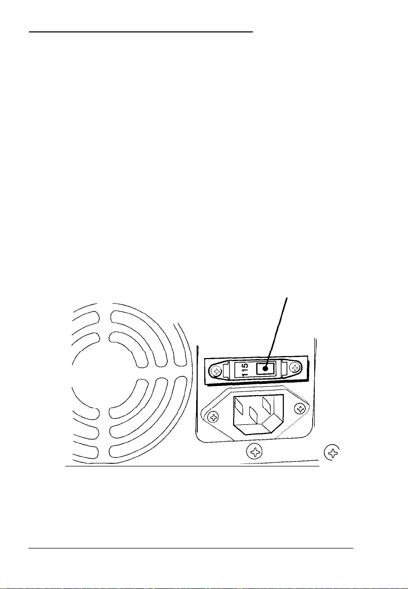
Setting the Voltage Selector Switch
Your system is powered by a 230 watt power supply. The
power supply voltage is controlled by a voltage selector switch
on the computer’s back panel that may be set to 115 VAC or
230
VAC.
The computer is shipped with the voltage selector switch set to
115 VAC. This setting is appropriate for line source voltages
between 100 and 120 VAC. This is generally the appropriate
setting if you will use the computer in North America or Japan.
If you plan to operate the computer in the United Kingdom or
Europe, you will almost certainly need to reset the voltage
selector switch to 230 VAC. Line source voltages between 200
and 240 VAC are acceptable with the switch set to 230 VAC.
If you need to change the voltage selector switch setting, refer
to the illustration below.
voltage selector switch
1-4
Setting Up Your System
Page 21
Caution
Before you turn on the power to your system, you must be
sure the voltage selector switch is set to the appropriate
setting for the electrical power source in your location or you
will seriously damage your system.
To change the voltage selector switch setting, insert the tip of a
ball-point pen or a similar tool into the dimple on the switch.
Then slide the switch to the right to select 115 VAC or to the left
to select 230 VAC.
Installing Optional Equipment
Before you set up and connect your system components, you
may want to install any optional equipment you plan to use.
Chapters 6 and 7 give complete instructions for installing
options such as disk drives, memory modules, and option cards.
You may want to list the serial numbers and other important
information about the options you install in the “Equipment
Note that the order in which you install option cards depends
on the type of cards you have. If you will be installing only ISA
option cards that did not come with their own configuration
(CFG) files, you should install them before you connect your
peripheral devices. Follow the instructions in your ISA card
manual to set the card’s switches or jumpers for your system.
You should also install any EISA cards you plan to use before
you connect peripheral devices so your EISA Configuration
utility can automatically detect the cards and configure them
correctly.
Setting Up Your System
1-5
Page 22
If you plan to install any ISA cards that came with their own
CFG files, you should install them after you have connected the
necessary peripheral devices and run the computer’s EISA
Configuration utility. This allows you to add the CFG file
information to your configuration so the program can give you
the card’s correct jumper and switch settings. Then you can set
the switches and jumpers and install the card. See the
documentation that came with your card(s) for information.
Be sure that the option card(s) you install do not exceed your
computer’s power supply limits, as described in Appendix B.
Then follow the instructions in Chapter 6 to install the cards,
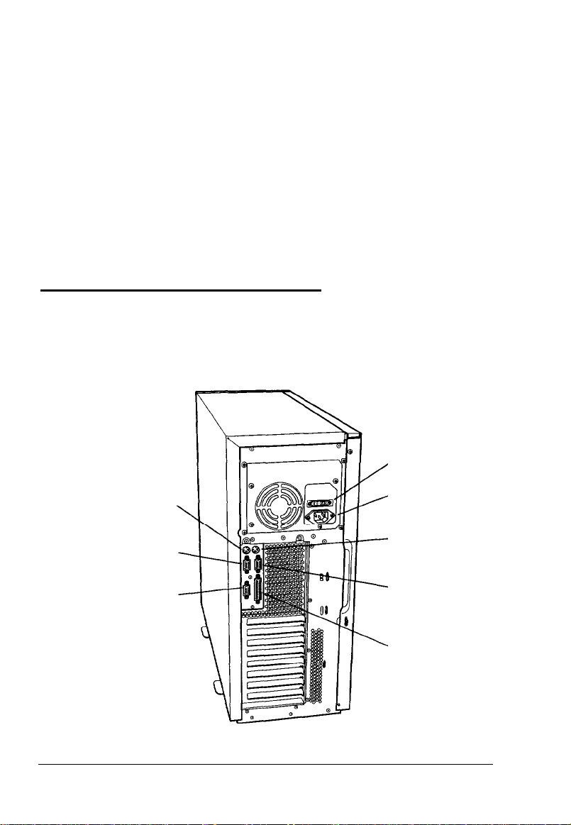
Connecting Peripheral Devices
Refer to the illustration below to locate the ports on the back of
your computer.
voltage
selector switch
1-6
keyboard port
serial port 2
VGA port
Setting Up Your System
AC inlet
mouse port
serial port 1
parallel port
Page 23

Before connecting the peripheral devices, make sure the power
buttons or switches on the computer and all peripheral devices
are turned off. Then follow these steps to connect the peripheral
devices:
1.
If necessary, insert the mouse cable connector into the
mouse port on the back panel.
Caution
Although the keyboard and mouse ports appear to be
identical, you cannot use them interchangeably. Be sure
to plug the keyboard and mouse into the correct ports.
2.
Insert the keyboard cable connector into the keyboard port
on the back panel.
3.
Connect the interface cables of any other peripheral devices
such as a monitor, printer, or modem to the appropriate
port on the back panel.
4.
Connect the power cords for any peripheral devices to
grounded electrical outlets.
5.
Plug one end of the computer’s power cord into the AC inlet
socket on the back panel.
6.
Plug the other end of the computer’s power cord into an
appropriate electrical outlet.
Be sure to read the next section before you turn on the system.
Setting Up Your System
1-7
Page 24

Turning On the System
Read the following safety rules to avoid damaging the
computer or injuring yourself:
cl
Do not connect any power or peripheral device cables when
the computer’s power is on.
cl
Never turn on the computer while a protective card is in a
5.25-inch diskette drive.
cl
Never turn on the computer when its cover is off.
Never turn off or reset your computer while a disk drive
cl
light is on. This can destroy data stored on the disk.
cl
Always wait at least five seconds after you turn off the
power before you turn it on again. This prevents possible
damage to the computer’s electrical circuitry.
ci
Do not leave a beverage near your system or any of its
components. Spilled liquid can damage the circuitry of
your equipment.
Ll
Always turn off the power and wait 30 seconds before you
disconnect the computer’s power cord and device cables,
and remove the cover. Only remove the cover to access
internal devices.
1-8
cl
Never press the computer’s power, reset, or
Keyboard/Mouse Lock buttons while the front panel is
removed.
Setting
Up
Your System
Page 25
Follow these steps to turn on the system:
1.
Make sure all peripheral devices, such as the mouse,
keyboard, and monitor, have been connected.
2.
Turn on the monitor and any other peripheral devices.
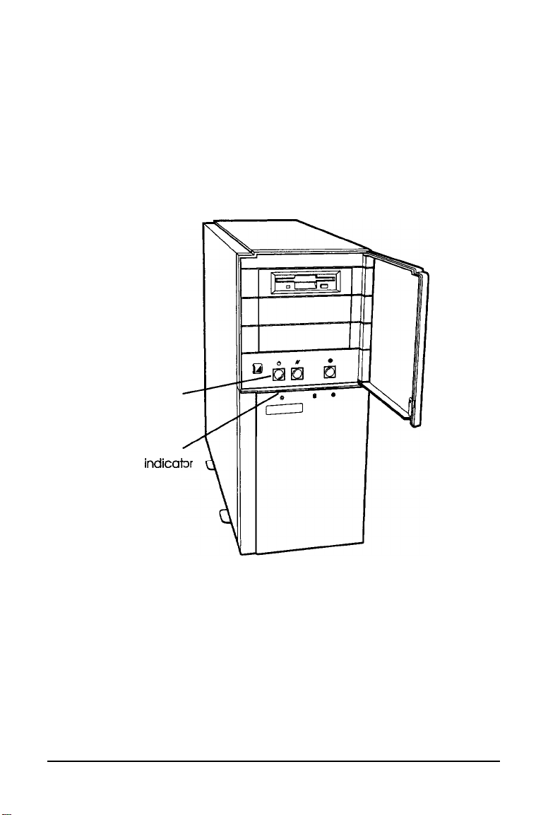
3.
Turn on your system by pressing the power button on the
front panel.
power
buttonbutton
powerpower
indicat
lightlight
4.
Verify that the power indicator light on the front panel is
on.
You are now ready to begin using your computer. See the next
section for information on configuring your system.
Setting Up Your System
1-9
Page 26

Configuring Your System
There are two programs you can use to configure your
computer: the SETUP program and the EISA Configuration
utility. Which one you use depends on the option cards you
may have installed in your computer.
You should use the SETUP program to configure your
computer in the following situations:
CL
You did not install any option cards or installed only ISA
option cards that did not come with configuration (CFG)
files
Cl
You do not have a diskette drive or have disabled your
diskette drive.
You should run the EISA Configuration utility to configure
your system if either of the following is true:
Cl
You have installed an EISA option card
Cl
You have installed an ISA option card that came with a
CFG file.
Your computer’s SETUP program is stored in the system BIOS
ROM. You can run SETUP whenever you turn on or reset the
computer, regardless of whether you have installed an
operating system. See Chapter 2 for instructions on running the
program.
The EISA Configuration utility is on the Reference diskette. See
Chapter 3 for instructions on running this utility.
1-10
Setting Up Your System
Page 27

Equipment Log
Use this space to record information about your system. You
should refer to this section if you call for assistance.
Computer serial number:
Purchase location:
date:
Monitor serial number:
Printer serial number:
Other device serial number:
Other device serial number:
Other device serial number:
Other device serial number:
Option cards installed:
Slot 1:
Slot 2:
Slot 3:
Slot 4:
Slot 5:
Slot 6:
Slot 7:
Slot 8:
Setting Up Your System
1-11
Page 28

IDE drives installed:
Bay 1:
Bay 2:
SCSI drives installed:
Bay 1:
Bay 2:
Bay 3:
Bay 4:
Bay 5:
Bay 6:
Other drives installed (diskette, tape, CD-ROM, etc.):
Bay 1:
Bay 2:
Bay 3:
Operating system version number:
Operating system serial number:
Software program
1-12
Setting Up Your System
Version number Serial number
Page 29

Chapter 2
Running the SETUP Program
The SETUP program allows you to configure your computer
and set many different system options. You should use SETUP
to configure your computer in the following situations:
Cl
You did not install any option cards or installed only ISA
option cards that did not come with configuration (CFG) files
Q
You do not have a diskette drive or have disabled your
diskette drive.
If you have installed EISA option cards, you should run the
EISA Configuration utility instead of the SETUP program to
configure your system. See Chapter 3 for more information.
Note
If you plan to operate your computer without either a
monitor, keyboard, or diskette drive, see “Using Special
Configurations” in Chapter 4 before running SETUP or the
EISA Configuration utility. If you’ll be redirecting your
computer’s input and output to a serial port, be sure to see
“Operating Your Computer from a Remote Location” in
Chapter 4 before configuring your system.
Your computer’s SETUP program is stored in the system BIOS
ROM. You can run SETUP whenever you turn on or reset the
computer, regardless of whether you have installed an
operating system.
Note
Any settings you make using the EISA Configuration utility
override those you set using SETUP.
Running the SETUP Program
2-1
Page 30
Starting the Program
Follow these steps to run SETUP:
1.
Turn on the computer or press the reset button. You see the
memory test countdown and then the power-on diagnostic
test countdown. You may also see this prompt:
Press Spacebar to Abort Memory Test
If you want to skip the memory test to shorten the time it
takes to enter SETUP, press the spacebar.
(If you press
does not perform the memory test.)
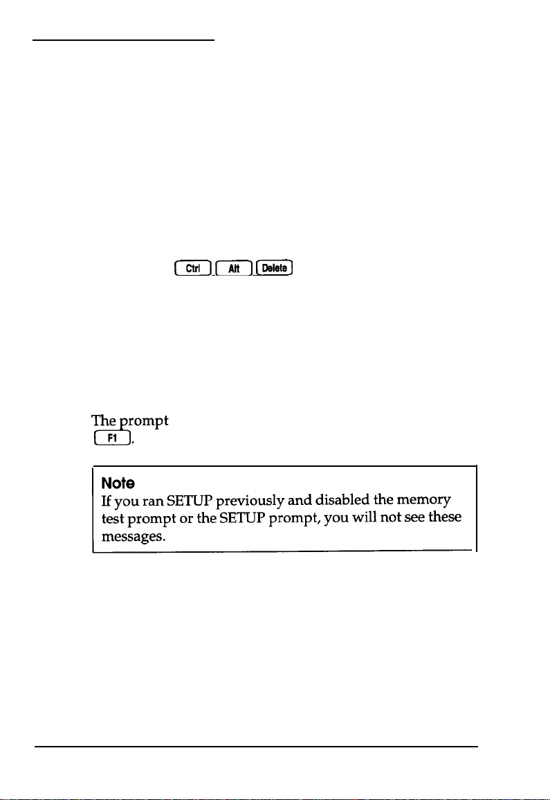
2.
If the power-on diagnostic tests do not find errors, you hear
a beep and may see the following prompt:
To continue press: . . . . . . . SPACEBAR
To configure system press: . . . F1
If the tests find a minor error or you have not yet installed
your operating system, the computer beeps twice; then you
see an error message and the following prompt:
To continue press: . . . . . . . SPACEBAR
To configure system press: . . . F1
[Ctrl) 171 [E]
remains on the screen for four seconds. Press
to reset the computer, it
2-2
Running the
SETUP
Program
Page 31

To continue without running SETUP, press the spacebar.
To run SETUP, press
[.
If the power-on diagnostic tests find a serious error, you hear
a beep code indicating the error and the system halts. See
Appendix A for a list of the error beep codes and suggested
solutions to the problem.
Now you see the first page of SETUP information:
Syatclm Time: 10:40:59
symtem
Date: Dot 12, 1993
Languacm:
Onhoard
Dhkette A: 3.5". 1.44 MB
Dimkott. Br
onhoard 1DE:EJlabl.d
Hard Driva 1: m
Eard
Drim 2:
Englimh
Plop~y:
Bhabled
Not
Not
User Definable
Izmtalled
3
Insitallsd
Drives:
-Disk Subsystem
Prec~anaation:
2and3
There are four pages of SETUP information. Follow the
instructions in the next section to view or change your
settings and display the other pages.
Selecting Options
To move the cursor from the current option to the next or
previous available option, press m or
more than one option on a line, you can also press
[-)
to move to the next or previous option.)
[.
(If there is
Page 1 of 4
Cylindora:
eordn: 13
Land
zone:
Stactora: 51
siza t
[tl
or
723
0
722
234
Running the SETUP Program 2-3
Page 32

To change the setting of the currently highlighted option, press
nor&
are numeric values, press a to select higher values and m to
select lower values.
To set default values or exit SETUP (with or without saving
your settings), press
you can press to perform these functions.
Press
(The system time and date options remain at their current
settings.) See “Exiting SETUP” on page 2-14 for information
about exiting SETUP.
to scroll through the available settings. If the settings
[.
You see a display listing the keys
[F5)
to set all the SETUP options to their default values.
Selecting Settings
The table below lists the settings available for each SETUP
option and describes how they affect your configuration. The
numbers in parentheses refer to notes at the end of the table.
When you finish changing your settings, see “Exiting SETUP”
on page 2-14.
SETUP program options
Option
System Time
system Date
Language
2-4 Running the SETUP Program
Settings
hh:mm:ss
dd month yyyy
English*
Français (French)
Deutsch (German)
Italiano (Italian)
Español (Spanish)
Set the current hour
(hh),
minutes
zi
Set the current day (dd), month,
and year (yyyy); automatically
tracks leap years
Set to the language in which you
want to display the SETUP
program text
Page 33

SETUP program options (continued)
Onboard
FlOPPY
Diskette A
Diskette B
Onboard IDE
Hard Drive 1
Hard Drive 2
Settings
Enabled *
Disabled
5.25”. 360 KB
1.2 MB
5.25”
3.5”, 720 KB
3.5”: 1.44 MB (A*)
3.5”, 2.88 MB
Not Installed (B*)
Enabled
Disabled *
Type nn
Not Installed l
Description
Set to Enabled to use the built-in
diskette drive controller; set to
Disabled to disable the built-in
controller if you are either not
using a diskette drive or will use a
controller on an option card
Set to the type(s) of diskette
drive(s) installed in the system; set
to Not Installed if you do not
have the specified drive installed
Set to Enabled to use the built-in
IDE hard disk drive controller to
control your IDE drive(s); set to
Disabled to use an external IDE
drive controller (1)
Set to the hard disk drive type of
the specified IDE hard disk drive
or enter parameters for
user-definable drive type
according to the drive’s
documentation; select the
user-defined drive type number
you want to use in the option
described below; select Not
Installed for both options if you
have installed a SCSI hard disk
drive. (For more information, see
“Hard Disk Drive Types” on
page 2-12.)
User Definable
Drives
2 and 3 *
48 and 49
Select the pair of user-definable
drive types you want to use to
enter your drive’s parameters;
select the type and enter the
parameters using the option
described above
Running the SETUP Program
2-5
Page 34

SETUP program options (continued)
Option
Video Type
640x480 Mode
Refresh Rate (3)
800x600 Mode
Refresh Rate
1024x768 Mode
Refresh Rate
Video Font
OnBoard
Video
Controller
Offboard
VGA/EGA
Adapter
Installed
Settings
VGA/EGA *
CGA40
CGA80
MDA
Not Installed
60Hz*
75 Hz
x2, x16 @72 Hz
-
-
8 x 16
9 x 16*
Primary l
Secondary
Yes *
No
Description
Select the type of adapter you
installed; if you are using the
built-in adapter, select VGA/EGA
(2)
Select the refresh rate frequency
(in Hertz) of the built-in video
controller when it is operating in
640 x 480 mode; see your
monitor manual to determine the
correct refresh rate
This option has no effect on your
system
This option has no effect on your
system
Select the font dimensions of the
video characters that appear on
the screen; select 9 x 16 for use
with VGA and most computer
programs
Set to Primary if you are using the
built-in video controller as your
primary display adapter; set to
Secondary to use the built-in
controller as the secondary
controller; if you install a VGA
display adapter card, the
computer may automatically
change the card to the primary
adapter and set the built-in
adapter to Secondary; all BIOS
video writes are directed to the
Primary video display
Set to Yes if you installed a video
display adapter on an option
card that contains a BIOS at
address C0000h; select No if you
have not installed a video option
card (4)
2-6 Running the SETUP Program
Page 35

SETUP program options (continued)
Option
Keyboard
NumLock on
at boot No*
Password
POST Memory
Test Prompt
Settings
installed
Not Installed *
Yes
Not installed *
Installed
Enabled *
Disabled
Description
Set to Installed to allow your
computer to operate with a
keyboard; set to Not installed to
use your computer without a
keyboard (for example, as a
network server) and allow
power-on diagnostic tests to
report a disabled keyboard
instead of a failed keyboard
Set to Yes to turn on Num Lock
mode whenever you turn on or
reset your computer; set to No to
turn it off
To set a power-on password,
highlight this option when the
setting is Not installed and press
m
or a. Then follow the
instructions on the screen to
enter the password; the setting
changes to Installed. (See
Chapter 4 for more information
about the password function.)
Set to Enabled to display the skip
memory test prompt when you
turn on or reset your computer;
select Disabled to prevent
display of the prompt. (You can
still press the spacebar to skip the
test if you disabled the prompt.)
See page 2-2 for more
information.
POST Setup
Prompt
Enabled *
Disabled
Set to Enabled to display the
prompt to run the SETUP program
when you turn on or reset your
computer; select Disabled to
prevent display of the prompt.
(You can still press [to run
SETUP if you disable the prompt.)
See page 2-2 for more
information.
Running the SETUP Program
2-7
Page 36

SETUP program options (continued)
Option
Boot Device
Select
Base Memory
Extended
Memory
Base Memory
Above 512K
Speaker
LCD
Onboard
Mouse
Settings
Floppy or Hard
Drive l
Hard Drive Only
640 KB *
512KB
(memory size]
Enabled *
Disabled
Enabled l
Disabled
-
Enabled *
Disabled
Description
Select the device(s) from which
you want to be able to boot your
system; setting is ignored if the
diskette drive is controlled by a
controller on an option card
Displays the size of the base
memory; setting is 640KB unless
there is a base memory failure or
you reassigned the base memory
between 512KB and 640KB in the
option described below
Displays the amount of extended
memory in the system including
memory installed on SlMMs and
any memory option cards; you
cannot change this setting
Set to Enabled to assign the base
memory address from 512KB to
640KB to memory on the system
board; set to Disabled if you
install an option card that
reserves these addresses for its
own use
Set to Enabled to turn on the
computer’s built-in speaker; set
to Disabled to turn off the
speaker (cannot be turned on by
application software if Disabled)
This option has no effect on your
system
Set to Enabled if you have
connected a mouse to the
built-in mouse port; set to
Disabled if you are not using a
mouse (frees hardware interrupt
lRQ12) or if you are using a
mouse controller installed on an
option card
2-8
Running the
SETUP
Program
Page 37

SETUP program options (continued)
Option
Parallel Port
Serial Port 1 (5)
Serial Port 2 (5)
Console
Redirection to
COM1
Console
Redirection to
COM2
Settings
Address 378H:
Compatible/lRQ7*
Address 278H:
Compatible/lRQ5
Address 378H:
Bi-directional/lRQ7
Address 278H:
Bi-directional/lRQ5
Disabled
Address 3F8H/IRQ4*
Address 2F8H/IRQ3
Address 3E8H/IRQ10
Disabled
Address 2F8H/IRQ3*
Address 3E8H/IRQ10
Address 2E8H/IRQ11
Disabled
Disabled*
1200 Baud
2400 Baud
9600 Baud
Disabled*
1200 Baud
2400 Baud
9600 Baud
Description
Select one of the Compatible
options to set the port for IBM AT
compatible signals: select one of
the Bi-directional options to set
the port for IBM PS/2 compatible
bi-directional signals; select
Disabled to prevent the port from
reacting to any signals (no
resources are allocated when
Disabled)
Select the address you want to
use for serial port 1; set to
Disabled to prevent the port from
reacting to any signals (no
resources are allocated when
Disabled)
Select the address you want to
use for serial port 2; set to
Disabled to prevent the port from
reacting to any signals (no
resources are allocated when
Disabled)
Set to Disabled to prevent
redirection of the computer’s
input and output to serial port 1:
set to the speed the computer
should use to copy the
redirected input/output to serial
port 1
Set to Disabled to prevent
redirection of the computer’s
input and output to the serial
port assigned as COM2; set to
the speed the computer should
use to copy the redirected
input/output to the port
Running the SETUP Program
2-9
Page 38

SETUP program options (continued)
Option
I/O Recovery
Time
Settings
Fast *
Slow
Enabled-
Write Through
Enabled-
Write Back
Disabled*
Standard
Enhanced l
Enabled l
Disabled
Description
Select Fast to set the computer’s
processor to operate at its
maximum speed; select Slow to
set the processor to operate at a
simulated 8 MHz speed to
accommodate old application
programs that may require it;
slow speed also disables any
system caching
Set to Enabled-Write Through to
enable caching on the
486DX2/66 CPU card; set to
Enabled-Write Back to enable
caching on the Pentium CPU
card; set to Disabled to prevent
caching when you are using
time-dependent software
Select Enhanced to set a fast I/O
recovery time; set to Standard if
you have trouble with an
application program or option
card that is running in Enhanced
mode
Set to Enabled to improve
performance by posting I/O
writes to the EISA bus; set to
Disabled if any of your option
cards do not support this feature
2-10
Concurrent
Refresh
Enabled l
Disabled
Running the SETUP
Set to Enabled to improve
performance by executing
concurrent CPU cache and
main memory refresh cycles; set
to Disabled if you have trouble
with any application programs
while this option is enabled
Program
Page 39

SETUP program options (continued)
Option
Onboard
Video BIOS
Mapping
Settings
To EOOOOH*
To COOOOH
Description
Select To E0000H to map the
onboard video BIOS to memory
address E0000h: select To C0000H
to map the video BIOS to
address C0000h to provide
compatibility with old
application software (6)
Shadow
C0000 to C7FFF
C8000 to CFFFF
E0000 to E7FFF
Scan FLASH
User Area
Disabled
Enabled
Enabled
Disabled
l
Set any of these options to
enable or disable shadowing of
ROM data from the indicated
memory address range (6)
Set to Enabled to allow the BIOS
l
to call any code you have
installed in the 8KB block EA000h
to EBFFFh prior to booting the
computer (FLASH user area); set
to Disabled to scan the block
normally
* Default setting
1
If you will boot your system from a SCSI hard disk drive, you must disable
the built-in IDE controller and set both hard disk drive types to Not
Installed.
2
When you select Not Installed for the Video Type option, the display type
bits are configured for VGA.
3
If you change the refresh rate, you must press the reset button or turn
the computer off and then on again after saving your settings to reset the
rate.
4 The Offboard VGA/EGA Adapter Installed option settings do not affect
your built-in video controller. To enable or disable this controller, you must
set jumper E0290. See Chapter 6 for more information.
5
You cannot set Serial Port 1 and 2 to the same address. If you attempt to
do so, you see an error message.
6 If you set the Onboard Video BIOS Mapping option to To C0000H, you
must set the Shadow C0000 to C7FFF option to Disabled to avoid a
memory conflict. If you set the Onboard Video BIOS Mapping option to
To E0000H, you must set the Shadow E0000 to E7FFF option to Disabled to
avoid a conflict.
Running the SETUP Program
2-11
Page 40

Hard Disk Drive Types
The following table lists the types of hard disk drives you can
use in your computer. Check this table and the manual that
came with your hard disk to find the correct type for the hard
disk drive(s) installed in your computer.
If your drive documentation includes only the drive parameters
and not a specific type number, search through this list to find a
type that matches your drive. If none of the types match, select
one of the user-defined drive types (2 and 3 or 48 and 49) and
set your own parameters using the Hard Drive n option. See
page 2-5.
Be sure you enter the correct drive type or parameters for
Hard disk drive types
2-12 Running the SETUP Program
Page 41

Hard disk drive types (con timed)
Running the SETUP Program 2-13
Page 42

Hard disk drive types (continued)
46 925 9
47
48,49 - - - - -
699
7
-1
256 700
925
17
17
69MB
40MB
User-definable
Exiting SETUP
To exit the SETUP program, press m at any of the SETUP
pages and follow the instructions on the screen to do any of the
following:
Ci
To continue running SETUP, press [ again.
Ll
CI
To load default settings for all the SETUP options, press
[;
the program erases any changes you have made
(except for the time and date).
Cl
To exit SETUP without saving your settings, press
then exit and reboot the
[.
2-14
Running the
SETUP Program
Page 43

Chapter 3
Running the EISA Configuration Utility
The EISA Configuration utility, provided with your system on
the Reference diskette, allows you to configure your computer
when you have installed the following option cards:
Q
EISA option cards
Cl
ISA option cards that came with configuration (CFG) files.
Use the program to do the following:
0
Learn about the configuration process
Li
Set the date and time
D
Copy the configuration (CFG) files for any option cards you
install
ci
Configure the system board and any option cards
ci
Create one or more System Configuration Information
(SCI) files
cl
Access other system utilities, such as password, CPU speed,
and cache utilities.
Note
If you plan to operate your computer without either a
monitor, keyboard, or diskette drive, see “Using Special
Configurations” in Chapter 4 before running the EISA
Configuration utility. If you’ll be redirecting your
computer’s input and output to a serial port, be sure to see
“Operating Your Computer from a Remote Location” in
Chapter 4 before configuring your system.
Running the EISA Configuration Utility 3-1
Page 44

You need to run the EISA Configuration utility to configure
your system with your EISA option cards installed before you
use your computer. You may need to run it again later if you
add or remove options, such as memory, disk drives, or option
cards.
After running the program, you save your current
configuration in the computer’s CMOS RAM and in a file called
SYSTEM.SCI. Your computer checks this information each time
you turn it on and assigns system resources based on the
configuration options you selected.
Once you configure your computer with this utility, you should
not use the SETUP program in your computer’s BIOS. Always
use the EISA Configuration utility to configure your computer.
If you want to create an alternate configuration for your
computer or another computer, you can create an alternate SCI
file. See page 3-25 for more information.
Note
The first time you configure your computer, you must run
the program from the Reference diskette and it is best to
always run it from there. However, you can run the EISA
Configuration utility from your hard disk to speed up its
performance. See page 3-31 for information on copying the
files to your hard disk. Then see page 3-27 for instructions on
running the utility from a command line.
3-2 Running the EISA Configuration Utility
Page 45

How to Use This Chapter
This chapter is divided into the following four sections:
LI
The Configuration Process
configuring your computer with the EISA Configuration
utility. It also tells you how to use the keyboard or a mouse
with the program and how to use on-line help.
Cl
Configuring Your System
instructions for running the EISA Configuration utility and
is organized in the order in which you should perform the
operations.
0
Using Alternate Configuration Files
create and use alternate configuration files, if this is
necessary.
c1
Using Special Modes
computer by running it in special operating modes, such as
non-target modeling mode.
Read “The Configuration Process” first to familiarize yourself
with all aspects of the configuration process. Then perform the
configuration operations in the order they are described under
“Configuring Your System.”
describes the various aspects of
provides step-by-step
explains how to
tells you how to configure your
If you need to create alternate configuration files or run the
program in special modes, see pages 3-25 or 3-27, respectively.
Running
the
EISA
Configuration
Utility
3-3
Page 46

The Configuration Process
This section describes the following configuration operations:
0
Using the configuration files
CI
Using the keyboard or a mouse with the program
Cl
Using on-line help.
Using Configuration Files
Configuration (or CFG) files provide information to the system
about a cards functions and resource requirements so your
computer can allocate its resources efficiently. They also
provide instructions for setting any switches and jumpers on
ISA cards.
You can copy to your Reference diskette a configuration file for
each card you install using the EISA Configuration utility. EISA
cards come with the necessary CFG file to allow the program to
configure the card automatically. See your EISA card
documentation for more information.
ISA option cards may come with the necessary CFG file for this
program. If you do not have a CFG file for your ISA card, you
can still install the card in your system. However, you should
configure the rest of your system and then follow the
instructions that came with the card to set any of its switches or
jumpers.
3-4
Running the
EISA Configuration Utility
Page 47

Using the Keyboard
If you use a keyboard when you run the EISA Configuration
utility, refer to the table below for a description of the keys you
can use to move the cursor and select items. If you’ll be using a
mouse with the program, see “Using a Mouse” below. Most of
the screens show which keys you can press to perform various
operations. Follow the instructions on each screen.
Whenever the <OK> icon is highlighted, press w to select
<OK>. To select <Cancel>, you can either press the
or highlight
<Cancel>
and press
mEntar
Key commands
[
key
Key
moor
m
[or
m
I
@j-J
[B
(xi-1 [End)
moor=
or
a
a
IPg
Function
Moves the cursor to the next field
Moves the cursor to the previous field
Highlights items within a list or scrolls the
screen
Selects the highlighted option
Cancels the current action or menu
Moves the cursor up or down one screen
Moves the cursor to the first line of
information
Moves the cursor to the last line of
information
Using a Mouse
The first time you run the EISA Configuration utility, you must
use the keyboard. After configuring your system, load your
operating system and then install your mouse driver. Then you
can run the utility using your mouse.
Running the EISA Configuration Utility
3-5
Page 48

To select most options, place the cursor on the option, click
once to highlight it, and again to select it.
When you see ? or 4 on the side of a screen, you can scroll the
text. Place the cursor on the arrow indicating the scroll
direction and hold down the mouse button. Release it to stop.
Keep in mind that this chapter gives keyboard instructions
when describing how to use the EISA Configuration utility.
You should substitute the appropriate mouse equivalents when
performing the same operations.
Using On-line He/p
The EISA Configuration utility provides extensive on-line help
information. You can obtain help in the following ways:
Cl
Highlight a menu option to see a description of its function.
D
Select Step 1:
information
the configuration process.
Q
Press the
following menu appears:
Press
press
3-6 Running the EISA Configuration Utility
[
EISA Configuration Help
Current screen
Selected item or board
All boards
Keys
Topics
Using help
EISA configuration
m
IEnter)
Important EISA configuration
for detailed information about each step in
key whenever you see
to highlight the help information you need; then
to select it.
Help=F1. The
Page 49

Configuring Your System
Follow the instructions in this section and on your screen to
configure your computer using the EISA Configuration utility.
You configure your system in the following order:
0
Set the date and time
Ct
Add or remove boards; when you add an option card,
select this option to copy the necessary configuration files
Ct
View or edit the details of your configuration; use this
option to define your configuration
LI
View or print your jumper and switch settings
Cl
Save the configuration as you exit the program.
Starting the Program
Follow these steps to start the EISA Configuration utility:
1.
Insert the Reference diskette in drive A and turn on or reset
the computer.
2.
After a moment, you see the title screen for the EISA
Configuration utility. Press B to continue. You see the
Welcome screen.
Note
If you installed any EISA option cards in your system,
you see a message telling you to configure your
computer. Press
IEnter]
to continue.
Running
the EISA Configuration Utility
3-7
Page 50

3.
Press IEnter You see the Main Menu:
Main Menu
Learn about configuring your computer
Configure computer
Set date
Set time
Access System Utilities
Maintain system configuration diskette
Exit from this utility
4.
For an overview of the configuration process, highlight
Learn about configuring your computer and
press [Enter. When you have finished reading the three
Help screens, press [Enter) to return to the Main Menu.
(You can press
time.)
Now set the date and time of your computer’s real-time clock,
as described below.
[
to return to the Main Menu at any
Setting
3-8 Running the EISA Configuration Utility
the Date
The real-time clock in your computer continuously tracks the
and
date
time you run the configuration program, set the date and time
for your computer. You can set them again later to adjust your
clock for seasonal time adjustments, such as daylight savings
time. The computer automatically changes the date for leap
years.
and Time
time-even when the computer is turned off. The first
Page 51

Follow these steps to set the date and time:
1.
At the Main Menu, select
as the following:
Date 12-12-1993 (mm-dd-yyyy)
2.
The current setting for
necessary. You can use the arrow keys to move the cursor
and overtype the date. Then press IEnter
3.
At the Main Menu, select
similar to the date prompt.
4.
You can use the arrow keys to move the cursor and overtype
the time. Then press
Now you can configure your computer, as described below.
Set date.
Date
[Enter.
is highlighted. Correct it as
Set time.
You see the Main Menu.
You see a prompt such
You see a prompt
Performing the Configuration Steps
Follow these steps to configure your computer:
1.
At the Main Menu, select
moment, you see this menu:
Configure computer.
After a
Steps in configuring your computer
Step 1:
Step 2:
step 3:
step 4:
step 5:
Important EISA
configuration information
Add or remove boards
View or edit details
Examine required switches
Save and exit
Running the EISA Configuration Utility 3-9
Page 52

Note
If you installed EISA option cards in your system, the
program first asks you to insert a diskette containing a
CFG file for the EISA card. Remove the Reference
diskette, insert the appropriate configuration diskette,
and press [Enter. Follow the instructions on the screen to
complete the installation and then go to the next step.
2.
Select
Step 1
screen about configuring your system. If you want to print
any of the screens to the printer connected to port LPT1,
press the
3.
Select
Step 2
add, remove, or move option cards in your configuration
and copy any necessary CFG files to your Reference
diskette. See the next section for more information.
4.
Select
Step 3
view or edit the details of your system board and your
option cards. See “Defining the Configuration Settings”
below for more information.
and read the information displayed on your
@E’
key.
and follow the instructions on the screen to
and follow the instructions on the screen to
3-10
5.
Select
Step 4
if you want to view or print the current
configuration and any switch or jumper settings you may
need to change. Follow the instructions on the screen.
6.
When you finish configuring your system, select
Step 5
to save the configuration in your computer’s CMOS RAM
and reboot the system. You can also exit the program
without saving the configuration, if necessary. Follow the
instructions on the screen.
Running the EISA
Configuration
Utility
Page 53

Adding or Removing a Board
Select
Step
add or remove an option card. The program displays a list of
the computer’s slots with a description of any cards that it
detects. The computer automatically detects EISA cards, but
you must add the necessary ISA card information. Follow the
instructions on the screen to add, move, or remove an option
card.
When you add an option card, you need the configuration
diskette that came with the card. Follow the instructions on the
screen to copy the appropriate CFG files to your Reference
diskette.
Add or remove boards
2
:
when you need to
Note
Your computer does not come with a CFG File Library
diskette. When adding a card, insert the CFG file diskette
that came with the card. If you are installing an ISA card that
did not come with a diskette, follow the instructions in the
card’s documentation to set the appropriate jumpers.
Defining the Configuration Settings
Select
Step 3 : View or edit details
configuration menu to view your system configuration options.
Then follow the instructions on the screen to edit the settings of
these options. You can also perform various advanced
configuration operations by accessing the Advanced menu. See
“Using the Advanced Configuration Options,” later in the
chapter, for more information.
You cannot change the settings for certain options because they
are detected and set automatically by the program. Some
options or settings may not be available, depending on the type
of
microprocessor
installed in your computer.
Running the EISA Configuration Utility
from the
3-11
Page 54

If you add any EISA option cards to your system, various
configuration options for the card(s) appear on the screen
following the system board options. See your EISA option card
documentation for information about configuring your card(s).
The table below describes the settings available for each of the
system board options. The numbers in parentheses refer to
notes at the end of the table.
System board options
Option
System
Processor
Module
System Board
Extended
Memory
System Base
Memory Option
User Definable
Hard Drives
Settings
(processor type)
(memory size)
Extended Memory
640KB Base Memory l
512KB Base Memory
Types 2 and 3 *
Types 48 and 49
Description
Displays the type of processor
module installed in your system
Displays the amount of
extended memory in the
system including memory
installed on SlMMs and any
memory option cards; you
cannot change this setting
Select 640KB to use all of this
memory as base memory;
select 512KB to reassign the
memory addresses from 512KB
to 640KB if you install an option
card that uses these
addresses
Select the pair of
user-definable drive types you
want to use; select the type
and enter the parameters at
the appropriate Hard Drive n
option(s) described below
3-12 Running the EISA Configuration Utility
Page 55

System
board
options (continued)
Option
Cache Control
Onboard
Floppy
Controller
Diskette A
Diskette B
Onboard IDE
Hard Disk
Controller
Settings Description
Cache Enabled-
Write Through Mode
Cache Enabled-
Write Back Mode
Cache Disabled*
Enable*
Disable
3.5 inch 1.44 MB drive*
3.5 inch 720 KB drive
3.5 inch 2.88 MB drive
5.25 inch 1.2 MB drive Disabled if you have removed
5.25 inch 360 KB drive your diskette drive
Diskette A Disabled
3.5 inch 1.44 MB drive
3.5 inch 720 KB drive drive installed as drive B in
3.5 inch 2.88 MB drive
5.25 inch 1.2 MB drive Disabled if you did not install a
5.25 inch 360 KB drive second diskette drive
Diskette B Disabled
Enable
Disable
l
Set to Enabled-Write Through
Mode to enable caching on
the 486DX2/66 CPU card; set
to Enabled-Write Back Mode
to enable caching on the
Pentium CPU card; set to
Disabled to prevent caching
when you are using time-
dependent software. You can
also turn cache control off
and on using the EISA System
Utilities; see Chapter 4.
Set to Enable to use the
built-in diskette drive
controller; set to Disable to
disable the built-in controller
and use a controller on an
option card
Set to the type of diskette
drive installed as drive A in
your system; set to Diskette A
Set to the type of diskette
your system; set to Diskette B
l
Set to Enable to use the
built-in IDE hard disk drive
controller to control your IDE
drive(s); set to Disable to use
an external IDE drive controller
(1)
Running the EISA Configuration Utility
3-13
Page 56

System board options (continued)
Hard Drive 1
and
Hard Drive 2
Parallel Port
Serial Port 1
Serial Port 2
Settings
Drive Type nn
Hard Drive n Disabled*
Base Address 378h -
Compatible*
Base Address 378h -
Bi-directional
Base Address 278h -
Compatible
Base Address 278h -
Bidirectional
Disabled
Base address 03F8h*
Base address 02F8h
Base address 03E8h
Disabled
Base address 02F8h *
Base address 03E8h
Base address 02E8h
Disabled
Description
Set to the hard disk drive type
of the specified IDE hard disk
drive or set to user-definable
drive types (2, 3, 48, or 49) and
enter parameters according
to the drive’s documentation;
see “Hard disk drive types”
below (1)
Select one of the Compatible
options to set the port for IBM
AT compatible signals; select
one of the Bi-directional
options to set the port for IBM
PS/2 compatible bidirectional
signals; select Disabled to
prevent the port from reacting
to any signals (no resources
are allocated when Disabled)
Select the address you want
to use for serial port 1; set to
Disabled to prevent the port
from reacting to any signals
(no resources are allocated
when Disabled) (2)
Select the address you want
to use for serial port 2; set to
Disabled to prevent the port
from reacting to any signals
(no resources are allocated
when Disabled) (2)
COM1
Redirection
Disabled*
1200 Baud
2400 Baud
9600 Baud
3-14 Running the EISA Configuration Utility
Set to Disabled to prevent
redirection of the computer’s
input and output to the serial
port assigned to COM1: set to
the speed the computer
should use to copy the
redirected input/output to the
serial port assigned to COM1
Page 57

System board options (continued)
Option
COM2
Redirection
Video Type VGA/EGA l
Offboard
VGA/EGA
Video Adapter
Onboard
Video
Controller
Settings
Disabled l
1200 Baud
2400 Baud
9600 Baud
CGA - 80 columns
CGA - 40 columns
MDA
Not Installed
No - Enable
Onboard Video
Controller via
Jumper*
Yes - Disable
Onboard Video
Controller via Jumper
Primary l
Secondary
Description
Set to Disabled to prevent
redirection of the computer’s
input and output to the serial
port assigned to COM2: set to
the speed the computer
should use to copy the
redirected input/output to the
serial port assigned to COM2
If you have installed a video
display adapter on an option
card, select the type of
adapter you installed; if you
are using the built-in video
controller, select VGA/EGA
Set to Yes if you have installed
a video display adapter on an
option card that contains a
BIOS at address C0000h; select
No if you have not installed a
video option card
Set to Primary if you are using
the built-in video controller as
your primary adapter; set to
Secondary if you are not using
your built-in controller. This
setting is ignored if jumper
E0290 is set to disable the
built-in VGA controller and
you set this option to Primary
Running the EISA Configuration Utility
3-15
Page 58

System board options (continued)
Option
Onboard
Video BIOS
Mapping
640 x 480
Mode Refresh
Rate (4)
800x600
Mode Refresh
Rate
1024 x 768
Mode Refresh
Rate
Shadow
C0000h-C7FFFh
C8000h-CFFFFh
E0000h-E7FFFh
Settings
To E0000H
l
To C0000H
Disabled
60 Hz*
75 Hz
x2, x16 @ 72Hz
-
-
Enabled
(E0000h - E7FFFh* )
Disabled
(C0000h - C7FFFh* )
Description
Select To E0000H to map the
onboard video BIOS to
memory address E0000h:
select To C0000H to map the
video BIOS to address COOOOh
for compatibility with older
application software; this
option is set to automatically
set to Disabled if you disable
the Onboard Video Controller.
as described above (3)
Select the refresh rate
frequency (in Hertz) of the
built-in video controller when it
is operating in 640 x 480
mode; see your monitor
manual to determine the
correct refresh rate
This option has no effect on
your system
This option has no effect on
your system
Set to Enabled to shadow
ROM data to the specified
memory address range in
RAM; set to Disabled to leave
data in ROM (3)
Keyboard
Control
Enabled
Disabled
l
3-16 Running the EISA Configuration Utility
Set to Enabled to allow your
computer to operate with a
keyboard; set to Disabled to
use your computer without a
keyboard (for example. as a
network server) and allow
power-on diagnostic tests to
report a disabled keyboard
Page 59

System board options ( Continued)
Option
Onboard Enabled*
Mouse Control
Speaker Enabled*
Control Disabled
CPU Speed
NumLock Boot
State
I/O Recovery
Time
Posted I/O
Writes
Settings
Disabled
FAST*
SLOW
ON at Boot
OFF at Boot*
Standard
Enhanced*
Enabled *
Disabled
Description
Set to Enabled if you have
connected a mouse to the
built-in mouse port; set to
Disabled if you are not using a
mouse (frees hardware
interrupt lRQ12) or if you are
using a mouse controller
installed on an option card
Set to Enabled to turn on the
computer’s built-in speaker;
set to Disabled to turn off the
speaker (cannot be turned on
by application software if
Disabled)
Select FAST to set the
computer’s processor to
operate at its maximum
speed; select SLOW to set the
processor to operate at a
simulated 8 MHz speed to
accommodate old
application programs that
may require it
Select ON at Boot to enable
Num Lock mode whenever
you turn on or reset your
computer; select OFF at Boot
to disable it
Select Enhanced to set fast
I/O recovery times; set to
Standard if you have trouble
with an application program
or option card that is running
in Enhanced mode
Set to Enabled to improve
performance by posting I/O
writes to the EISA bus; set to
Disabled if any of your option
cards do not support this
feature
Running the EISA Configuration Utility
3-17
Page 60

System board options (continued)
Option
Concurrent
Refresh Disabled
LCD
Scan FLASH
User Area
POST Memory
Test Prompt
Settings
Enabled*
-
Enabled
Disabled*
Enabled *
Disabled
Description
Set to Enabled to improve
performance by executing
concurrent CPU, cache, and
main memory refresh cycles;
set to Disabled if you have
trouble with application
programs while this option is
enabled
This option has no effect on
your system
Set to Enabled to allow the
BIOS to call any code you
have installed in the 8KB block
EA000h to EBFFFh (FLASH user
area) prior to booting the
computer; set to Disabled to
scan the block normally
Set to Enabled to display the
skip memory test prompt
when you turn on or reset your
computer; select Disabled to
prevent display of the prompt.
(you can still press the
spacebar to skip the test if you
disabled the prompt.) See
Chapter 2 for more
information.
BIOS Setup
Control
Enabled - Prompt for Select Enabled - Prompt for
setup entry *
Enabled - Suppress prompt to run the SETUP
setup prompt
Setup Disabled
3-18 Running the EISA Configuration Utility
setup entry to display the
program when you turn on or
reset the computer; select
Enabled - Suppress setup
prompt to prevent display of
the prompt; select Setup
Disabled to prevent entry into
the SETUP program until this
option is changed
Page 61

System board options (continued)
Option
Boot Device
Control
Reserved
System
Resources
* Default setting
1
If you will boot your system from a SCSI hard disk drive, you must disable
the built-in IDE controller and set both hard disk drive types to Disabled.
2
You cannot set Serial Port 1 and 2 to the same address. If you attempt to
do so, you see an error message.
3
If you set the Onboard Video BIOS Mapping option to To C0000H. you
must set the Shadow C0000h - C7FFFh option to Disabled to avoid a
memory conflict. If you set the Onboard Video BIOS Mapping option to
To E0000H, you must set the Shadow E0000h - E7FFFh to avoid a conflict.
4
If you change the refresh rate, you must press the reset button or turn
the computer off and then on again after saving your settings to reset the
rate.
5
The Boot Device Control setting is ignored if the diskette drive is controlled
by a controller on an option card.
Settings
Boot from floppy or
hard drive*
Boot from hard drive
ONLY
(settings vary)
Description
Select the device(s) from
which you want to be able to
boot your system (5)
Press
w
and
m
to
display the resources, such as
interrupts and port ranges,
that are reserved for use by
the system board
Running the EISA Configuration Utility
3-19
Page 62

The options described in the table below appear on the View
or edit details screen only if you are running the EISA
Configuration utility in Advanced mode. See “Using Special
Modes” on page 3-27 for more information.
Advanced mode system board options
Option
Video Font Size
Extended (settings vary)
Memory Range
Definitions
Additional
expansion
board address
Slot 4 AEN
Control
Settings Description
9x16*
8x16
Enabled
Disabled
EISA Compatible
ISA Compatible
l
Select the font dimensions of the
video characters that appear on
the screen
Displays the defined ranges of
memory resident on the system
board
If you have installed more than
15MB of memory in your system,
you may want to set this option to
Enabled to map additional
address space to the EISA bus for
use by option cards. Enabling this
space opens a 1 MB to 128KB
area between addresses
0F00000h and 0FE0000h and
reduces the available extended
memory by 1 MB. Select Disabled
to use this address area for
extended memory.
l
When slot 4 is set to EISA
Compatible, it uses the EISA
geographical addressing
scheme. If you set slot 4 to ISA
Compatible, it allows all types of
I/O accesses that may be
required by option cards
addressed in the range 0-255.
* Default setting
3-20
Running
the EISA Configuration Utility
Page 63

Hard disk drive fypes
The following table lists the types of hard disk drives you can
use in your computer. Check this table and the manual that
came with your hard disk to find the correct type for the hard
disk drive(s) installed in your computer.
Be sure you enter the correct drive type or parameters for
your drive; if they are incorrect, the computer will not
Hard disk drive types
07 918
08
09 900
10
11
12
13
14
16
17
-
977
855
855
- - - - Unused
733
615
-
15
15
5
5
7
7
4
-
Running
-1
- -
-1
0
-1
-1
-1
-1
- -
17
17
17
17
17
17
17
114 MB
Unused
112 MB
40 MB
35 MB
49 MB
42 MB
20 MB
Unused
the EISA Configuration Utility
3-21
Page 64
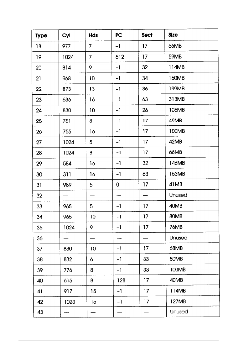
Hard disk drive types (continued)
3-22
Running the EISA Configuration Utility
Page 65

Hard disk drive types (con timed)
Using Advanced Configuration Options
To perform advanced configuration operations, press
the
View or edit details
menu:.
Lock/unlock boards
View additional system information menu
Set verification mode menu
Maintain SCI files menu
screen. You see the Advanced
[nl
at
Running the EISA Configuration Utility 3-23
Page 66

The table below describes the operations you can select from
the Advanced menu and its submenus.
Advanced configuration options
Advanced
menu option
Lock/unlock
boards
View additional
system
information
menu
Set verification
mode menu
Maintain SCI
files menu
Submenu
option
No submenu
Board
specifications
System
specification:
Used
resources
Available
resources
Manual
Open
Save as
Description
Displays the locked/unlocked status of
each board. Locking a board prevents
you from changing any of its
configuration settings.
Displays information about the
identification and physical
characteristics of your board(s).
Displays information about the Option
slots in your computer.
Displays information about the
currently used system resources such as
IRQ levels, interface ports, and memory
addresses and defines which
components are using the resources.
Displays information about unassigned
system resources such as IRQ levels,
interface ports, and memory addresses.
Sets the program to automatically
check for resource conflicts and report
them, if they occur (default setting).
Sets the program so it does not check
for resource conflicts unless you select
the Verify option that appears on the
View or edit details screen. (The Verify
option appears only if you have
selected Manual verify.)
Loads a previously created SCI file and
displays the contents. Any current
configuration information you entered
is lost.
Saves the current SCI file information to
a backup file. Do not name the
backup file SYSTEM.SCI.
3-24 Running the EISA Configuration Utility
Page 67

Using Alternate Configuration Files
When you save your configuration in your computer’s CMOS
RAM, the computer also creates or updates the System
Configuration Information file called SYSTEM.SCI. You can
also create an alternate SCI file with a different name for your
own computer or for another Epson EISA computer.
You may want to create an alternate configuration for your
own computer that includes a different set of option cards.
Then, whenever you need to use that configuration, you can
load the alternate SCI file and save it in your computer’s CMOS
RAM.
If you run the EISA Configuration utility on a non-target
computer (an IBM AT compatible computer or another Epson
EISA computer), you can create a file for the target computer.
Then you can transport the alternate SCI file to the target
computer, load it, and save it in that computer’s CMOS RAM.
To create an alternate SCI file, follow the guidelines in the next
section. To load an alternate SCI file when you need to use one,
see “Loading an Alternate SCI File” below.
Creating an Alternate SCI file
You can create an alternate SCI file using the following methods:
Cl Select
Q
Q
Create backup SCI file
system configuration diskette menu.
Select the
menu when you are using the advanced configuration
options.
Run the EISA Configuration utility in non-target modeling
mode and save the configuration you create to a backup
SCI file when you exit.
Save as
Running the EISA Configuration Utility 3-25
option from the Maintain SCI files
from the Maintain
Page 68

The program asks you to name the alternate SCI file you create.
Do not name the file SYSTEM.SCI; this is the name of your
current configuration file.
Use the third method only when you are running the
configuration program on a non-target computer. This method
protects you from accidentally saving the configuration you
create in that computer’s CMOS RAM. See “Using Special
Modes” for instructions on using non-target modeling mode.
Loading
an Alternate SCI File
To load an alternate SCI file and store it in the target
computer’s CMOS RAM, follow these steps:
1.
Run the EISA Configuration utility and select
system configuration diskette from
Menu.
2.
Select
Load a backup SCI file.
3.
Select the alternate SCI file you want to load from the list of
SCI files displayed on the screen.
4.
Exit and save the SCI file in the computer’s CMOS RAM.
Note
You can also load-an alternate SCI file by selecting
from the Maintain SCI files menu when you are using the
advanced configuration options. (See page 3-23.) This
method allows you to load the file while you are looking at
the View or edit details screen for another configuration.
However, the Open option erases the currently loaded
configuration before loading the new file.
Maintain
the Main
open
Now the computer is configured according to the information
in the alternate SCI file.
3-26 Running the EISA Configuration Utility
Page 69

Using Special Modes
You can run the EISA Configuration utility in various special
modes, including non-target modeling mode, by starting the
program with one of the two commands described in this
section. You can also use these commands to run the utility
from a hard disk that runs MS-DOS if you copy the necessary
files to the disk first.
The SD command starts the EISA Configuration utility and also
allows you to run any of the other utilities available on the
Access to other utilities menu. The CF command also starts the
EISA Configuration utility, but you cannot run any other
utilities.
You can run the utilities in different modes by including one or
more parameters on the SD or CF command line, as described
in the next sections.
Using the SD Command
If you want to run the utilities from your hard disk, first follow
the instructions under “Copying the Configuration Files to a
Hard Disk” below. Then follow these steps to use the SD
command:
1.
To run the utilities from a diskette, insert the Reference
diskette in drive A and log onto drive A.
To run the utilities from a hard disk, log onto the drive and
directory where you copied the configuration files.
2.
Type the following and press m to start the program:
SD
[parameters1
Running the EISA Configuration Utility 3-27
Page 70

The table below describes the parameters you can use to
modify the way the program runs on your computer.
Note
To run the EISA Configuration utility in non-target
modeling mode, add the /N parameter to the command line.
Modeling mode only affects the way the configuration utility
operates; it does not affect any of the other utilities you can
run using the SD command.
SD command parameters
Parameter
/A
/B
/F
/H
Mode
Advanced
mode
BIOS video
output mode
Fast
configuration
operation
High resolution
display mode
Function
Enables four advanced options for
the system on the View or edit
details screen; see page 3-23 for
more information. You can also
enter this mode by pressing
In) at the Welcome screen when
you start the EISA Configuration
utility.
Causes the program to be
displayed using BIOS int 10h calls for
systems using non-standard displays
or that are redirecting the console
output to a serial port. In default
mode, the program writes directly
to the video memory.
Causes the program to determine
the boards and options installed
and configure your system
automatically using the information
in the CMOS RAM; if it is invalid, the
program uses the information in the
SYSTEM.SCI file.
Displays 43 lines per screen on an
EGA monitor and 50 lines per
screen on a VGA monitor. In
default mode, the screen displays
25 lines.
Ictr(J
3-28
Running the EISA Configuration Utility
Page 71

SD command parameters (continued)
Parameter
/K
/M
/N
/P
Mode
Keyboard only
mode
Monochrome
display mode
Non-target
modeling mode
Permanent
command
interpreter mode exiting to your operating system.
Using the CF Command
Function
Sets the program so a mouse
cannot be used, even if you have
installed one. In default mode, you
can use a mouse as long as a
mouse driver is loaded.
Causes the program to be
displayed in black and white only.
In default mode, color monitors will
display in color. Run the program in
this mode if you have redirected
the console output to a serial port.
Allows you to run the EISA
Configuration utility in non-target
modeling mode; see page 3-25 for
more information.
Causes the configuration program
to reboot the system instead of
Use this mode if there is no
COMMAND.COM file installed on
your hard disk drive.
If you want to run the EISA Configuration utility from your
hard disk, first follow the instructions under “Copying the
Configuration Files to a Hard Disk” on page 3-31.
Then follow these steps to use the CF command:
1.
To run the utility from a diskette, insert the Reference
diskette in drive A and log onto drive A. To run the utility
from a hard disk, log onto the drive and directory where
you copied the configuration files.
Running the EISA
Configuration
Utility
3-29
Page 72

2.
Then type the following and press ( to start the
program:
CF [parameters]
The table below describes the parameters you can use to
modify the way the utility runs on your computer.
CF command parameters
Parameter
IA
/B
/D
/F
/H
Mode
Advanced
mode
BIOS video
output mode
Dispatcher
spawning mode
Fast
configuration
operation
High resolution
display mode
Function
Enables four advanced options for
the system on the View or edit
details screen; see page 3-23 for
more information.
Causes the program to be
displayed using BIOS int 10h calls for
systems using non-standard displays
or that are redirecting the console
output to a serial port. In default
mode, the program writes directly
to the video memory.
Causes the program to be
spawned by the dispatcher.
Causes the program to determine
the boards and options installed
and configure your system
automatically using the information
in the CMOS RAM; if it is invalid, the
program uses the information in the
SYSTEM.SCI file.
Displays 43 lines per screen on an
EGA monitor and 50 lines per
screen on a VGA monitor. In
default mode, the screen displays
25 lines.
3-30
/K
Running
Keyboard only
mode
Sets the program so a mouse
cannot be used, even if you have
installed one. In default mode, you
can use a mouse as long as a
mouse driver is loaded.
the EISA Configuration Utility
Page 73
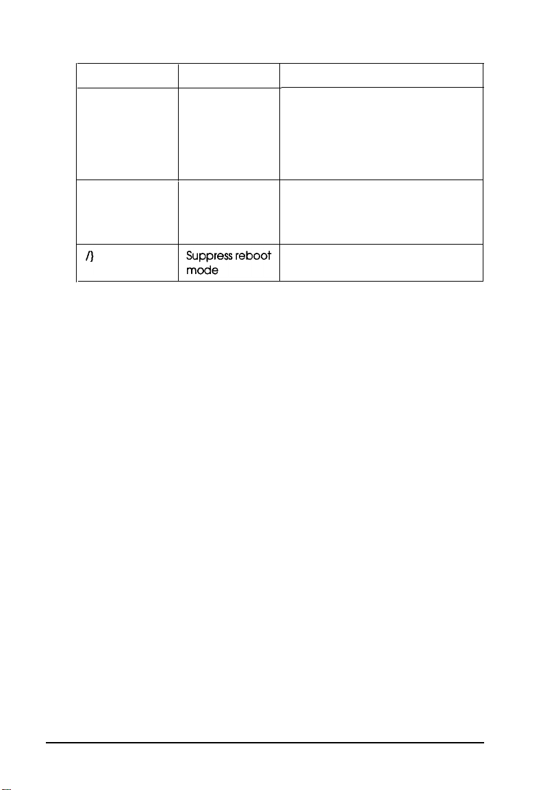
CF command parameters (continued)
Parameter
/M
/N
Copying
the Configuration Files to a
Mode
Monochrome
display mode
Non-target
modeling mode
Function
Causes the program to be
displayed in black and white only.
In default mode, color monitors will
display in color. Run the program in
this mode if you have redirected
the console output to a serial port.
Allows you to run the EISA
Configuration utility in non-target
modeling mode; see page 3-25 for
more information.
Causes the program to exit without
rebooting the computer.
Hard
Disk
To run the EISA Configuration utility from your hard disk, you
must be running MS-DOS from that disk.
To copy all the configuration files from the Reference diskette
to the hard disk, insert the diskette in drive A, type the
following command, and press [Enter:
COPY A:*.* [d:] [path]
where d: and path are the drive and directory to which you
want to copy the files.
Running
the EISA Configuration Utility
3-31
Page 74

Chapter 4
Using Your Computer
This chapter describes the following operations:
Q
Locking the computer’s cover
c3
Locking the front panel door
D
Disabling the keyboard and mouse
Cl
Using the password features
Ll
Locking the keyboard
0
Changing the processor speed
Q
Controlling the speaker
a
Controlling the cache
tl
Using the security features
Q
Using special configurations
Ci
Operating the computer from a remote location.
locking the Computer’s Cover
You can lock the cover onto the computer to prevent
unauthorized users from accessing its internal components. To
do this, you need a padlock that fits through the hole in the lock
block on the computer’s back panel. When the padlock is in
place, the cover on the computer cannot be removed.
Using Your Computer
4-1
Page 75

You can also secure the computer to your work area by
inserting a cable lock through the lock block and then through a
secure anchor.
To lock the cover, insert a padlock or cable lock through the
hole in the lock block.
cover lock
To unlock the cover, remove the padlock or cable lock.
Locking the Front Panel Door
You can lock the door that covers your computer’s front panel
to prevent unauthorized users from accessing the following
components:
Cl
Diskette, tape, CD-ROM, or other external drives
Cl
Power and reset buttons
0
Keyboard/mouse lock button.
4-2
Using
Your Computer
Page 76

Your computer comes with two keys that you can use to lock
the front panel door. The keys are taped to the inside of the
door. Open the front panel door and remove the keys from the
bag.
To unlock the front panel door, align the key with the notch in
the lock and insert the key, as shown below. Then press in the
key and turn it clockwise.
To lock the cover, align the notches and insert the key; then
push it in and turn it counterclockwise.
Be sure to store these keys in a secure location.
Using Your Computer
4-3
Page 77

Disabling the Keyboard and Mouse
You can disable the operation of your computer’s keyboard and
mouse to prevent unauthorized users from executing any
keyboard or mouse commands. To do this, press the
Keyboard/Mouse Lock button on the front panel, as shown
below. The computer disables the keyboard and mouse, and
illuminates the Keyboard/Mouse Lock indicator light.
To prevent access to the Keyboard/Mouse Lock button, follow
the instructions on page 4-2 to lock the computer’s front panel
door.
keyboard/
mouse
lock
button
keyboard/
mouse
lock
indicator
To reactivate the keyboard and mouse, unlock the front panel
door (if necessary), and press the Keyboard/Mouse Lock
button again. The Keyboard/Mouse Lock indicator light goes
out.
You can temporarily disable the keyboard and mouse using
software commands. See Chapters 2 and 3 for more
4-4
Using
Your Computer
Page 78

Using the Password Features
You can set three types of passwords to provide security for
your computer:
Ll
Power-on password
Ci
Network password
Q
Keyboard password.
The power-on password prevents unauthorized users from
using your system by requiring you to enter the correct
password every time you turn on or reset the computer.
The network password modifies the way your power-on
password works by allowing your computer to load your
operating system and network software before requiring you to
enter the correct password. This enables your system to connect
to the network, while preventing unauthorized users from
typing anything at the keyboard.
The keyboard password allows you to temporarily lock the
keyboard without having to reset the computer. This secures
your system when you will be away from it for a while. If you
set a power-on password, it automatically becomes your
keyboard password as well. However, you can set a different
keyboard password or set a keyboard password without setting
a power-on password.
Follow the instructions in the sections below to set, enter,
change, or delete the different types of passwords.
Using Your Computer
4-5
Page 79

Setting Passwords
There are two ways to set a power-on password:
tl
Using the SETUP program
Cl
Using the EISA System Utilities.
To set a power-on password in SETUP, follow the instructions
in Chapter 2 for starting and running the program. Select the
Password option on the second page of SETUP options and
follow the instructions on the screen to set a password.
You must run the EISA System Utilities to set a network and
keyboard password, but you can also use it to set a power-on
password.
Follow these steps to set your password(s):
1.
To start the EISA Configuration utility, insert the Reference
diskette in drive A.
2.
Log onto drive A and type
screens to bring up the Main Menu.
SD.
Press [Enter at the next two
3. Select Access System Utilities.
4.
Then select
Set Initial Power-on Password
Activate/Deactivate Network Password
Set Keyboard Password
Lock Keyboard
Return to Utilities Menu
Now follow the steps in the appropriate section(s) below.
4-6
Using Your Computer
Password Utility.
Password Utility Menu
You see the following:
Page 80

setting a power-On password
To set a power-on password, follow these steps:
1.
Select
Set Initial Power-on Password
Password Utility Menu.
2.
You see a prompt to enter a password of up to seven
characters. Follow the instructions on the screen to enter the
password twice and return to the Password Utility Menu.
3.
Your power-on password is also now your keyboard
password. If you want to set a different keyboard
password, see “Setting a keyboard password” below.
If you will be using your computer in a network, follow the
steps in the next section to activate a network password.
Activating a network password
To
activate
1.
First set a power-on password as described above.
2.
Select
a network password, follow these steps:
Activate/Deactivate
the Password Utility Menu,
Network
at the
Password
from
3.
At the Network Password menu, select
Activate
Network Password.
4.
You see a message confirming the activation. Press IEnter
You see the Password Utility Menu.
To deactivate a network password, follow the steps above, but
select
De-activate Network Password
instead. If you
want to set a different keyboard password, see the next section.
Using Your Computer
4-7
Page 81

Setting a keyboard password
Once you set a power-on password, it automatically becomes
your keyboard password as well. If you want to use a different
password for the keyboard, you can set one with the Set
Keyboard Password option. This password takes effect only
temporarily, however; when you turn off your computer, the
power-on password again becomes your keyboard password.
You can also set a keyboard password without setting a
power-on password, but when you turn off your computer or
press the reset button, it erases the keyboard password.
Follow these steps to set a keyboard password:
1.
Select Set
Keyboard
Password
at the Password Utility
Menu.
2.
You see a prompt to enter a new password that will be your
keyboard password. Type a new password and press
[Enter.
3.
At the next prompt, enter the password again. You see the
Password Utility Menu.
Whenever you want to lock your keyboard temporarily, follow
the steps on page 4-4.
Entering Passwords
If you set a power-on password, you must enter it each time
you turn on the computer, press the reset button, or press
[ctrl) [Al) 1E).
password.
If you set a keyboard password, you can lock your keyboard,
and then you must enter your keyboard password to unlock it.
See page 4-4 for instructions on locking your keyboard and
entering your keyboard password.
4-8
Using Your Computer
This is also true if you activate a network
Page 82

Follow these steps to enter a power-on password:
1.
When you turn on your computer, press the reset button, or
press
Ictrl) IX)
(Delete], you see the following prompt:
Enter password:
2.
Type your password and press
[.
The screen does not
display what you type.
After you enter the correct password, you see
Password
and the computer loads your operating system.
If you do not enter the correct password, you
is
incorrect
and another prompt to enter the password.
see Password
You have two more chances to enter the correct password; try
again.
If you do not enter the correct password at the third prompt,
you see the following message:
System halted! Must power down.
The computer locks the keyboard. Press the reset button or turn
the computer off and on; then try to enter the correct password
again.
Changing or Deleting Passwords
You can change or delete the power-on password whenever
you
see the Enter password:
section.
prompt, as described in this
OK
However, you cannot change or delete the power-on password
if a network password is activated. See page 4-7 for instructions
on deactivating the network password and then return to this
section to change or delete the power-on password.
Using Your Computer
4-9
Page 83

There are several methods you can use to change or delete a
keyboard password. See the appropriate section(s) below to
change or delete your password(s).
Changing or deleting a power-on password
To change or delete a power-on password, follow these steps:
1.
Enter
2.
To change the password, type the current password followed
password:
by a forward slash (/). After the slash, enter the new
password, another slash, and the new password again. For
example:
123/ABC/ABC
To delete a password, type the current password followed
only by a forward slash (/). For example:
123/
(The screen does not display what you type.)
3.
Press
m.
You see a message confirming the change or
deletion.
4-10
Using Your Computer
Page 84

Changing or deleting a keyboard password
If your keyboard password is the same as your power-on
password, follow the steps in the section above to change or
delete it. Then reboot your system.
If your keyboard password is different from your power-on
password, you can make both passwords the same by turning
off or resetting your computer. The keyboard password
becomes the same as your power-on password.
To temporarily change your keyboard password to something
other than your power-on password, follow these steps:
1.
To start the EISA Configuration utility, insert the Reference
diskette in drive A.
2.
Log onto drive A and type
SD. Press
[Enter] at the next two
screens to bring up the Main Menu.
3.
Select
Access System Utilities.
4.
Select
Password Utility.
5.
Thenselect
Set Keyboard Password.
You see a message
telling you that a keyboard password already exists. Press
IEnter
6.
The computer locks the keyboard and you see a prompt to
enter your password. Type your power-on password and
press Enter .
d
7.
You see a prompt to enter your new keyboard password.
Type a new password and press
8.
At the next prompt, enter the password again. You see the
[Entsr].
Password Utility Menu. Follow the instructions on the
screen to exit the EISA Configuration utility.
Using
Your Computer
4-11
Page 85

Locking the Keyboard
You can temporarily lock the keyboard to secure your system
when you are going to leave it unattended. Then, when you
return, you can enter a special keyboard password to unlock it.
To lock your keyboard, you must first set a keyboard
password, as described on page 4-8. Then follow these steps
whenever you want to lock your keyboard:
1.
To start the EISA Configuration utility, insert the Reference
diskette in drive A.
2.
Log onto drive A and type SD. Press m at the next two
screens to bring up the Main Menu.
3. Select Access System Utilities.
4.
Then select Password Utility. You see the following:
Password Utility Menu
Set Initial Power-on Password
Activate/Deactivate Network Password
Set Keyboard Password
Lock Keyboard
Return to Utilities Menu
5. Select Lock Keyboard.
6.
The computer locks the keyboard and you see the following
prompt:
KEYBOARD LOCKED
The keyboard has been locked. Please
enter the keyboard password to unlock it:
4-12
Using Your Computer
Page 86

When you are ready to use your computer again, type your
keyboard password and press IEnter You see the Password
Utility Menu.
If you enter an incorrect password, the prompt remains on
the screen. Try entering it again; you can try as many times
as you want.
7.
Follow the instructions on the screen to exit the EISA
Configuration utility.
Changing the Processor Speed
Your computer’s processor can operate at two speeds: high and
low. High speed is the maximum speed of your microprocessor
and low speed simulates an 8 MHz processor speed to provide
compatibility with certain older application programs. (See
your program manual to see if you need to set your processor
speed to low.)
You set the default processor (or CPU) speed when you ran
either the SETUP program or the EISA Configuration utility
(described in Chapters 2 and 3). If necessary, you can
temporarily change the processor speed using keyboard
commands or the EISA System Utilities.
If you often use programs that require the processor to operate
at low speed (8 MHz), use the SETUP program or EISA
Configuration utility to set the default CPU speed to low. See
Chapters 2 and 3 for instructions. If you use these programs
only occasionally, use the keyboard commands or the EISA
System Utilities program, described below, to change the
processor speed temporarily.
Using Your Computer 4-13
Page 87

Entering Keyboard Commands
To change the processor speed, enter one of the keyboard
commands shown in the table below.
Keyboard speed setting commands
Key command Function
mm1
Ictrl]m2
Changes the speed to low (simulated 8 MHz)
Changes the speed to high
You must use the 1 or 2 key located on the numeric keypad.
When you set the speed to low, you hear a low tone from the
computer’s speaker; when you set it to high, you hear a high
tone. The speed setting remains in effect until you press the
reset button or turn off the computer, or until you change the
setting.
Note
You can use these commands while you are running a
program. However, if that program uses the key command
for another function, you cannot use it to change the
processor speed. If this is the case, exit to your operating
system command prompt and try the command or use the
EISA System Utilities to change the speed, as described
below.
4-14
Using
Your
Computer
Page 88

Using the EISA System Utilities
You can temporarily change the processor speed using the
EISA System Utilities. This method is convenient if your
application program does not recognize the
commands to change the processor speed. Follow these steps:
1.
Insert the Reference diskette in drive A.
[F] [An]
key
2. Log onto drive A and type
SD. Press w at the
screens to bring up the Main Menu.
3. Select
Access
System utilities
from the Main Menu.
You see the following:
System Utilities Menu
Password Utility
System Speed FAST
System Speed SLOW
Speaker ON
Speaker
OFF
Cache ON
Cache OFF
EXIT Utilities
4.
Select
System Speed FAST
or
System Speed SLOW.
You see a message confirming the speed change.
5.
Press
m
to return to the System Utilities Menu. Then
follow the instructions on the screen to exit the EISA
Configuration utility.
next two
The processor speed you set remains in effect until you press
the reset button, turn off the computer, or change it to a
different setting.
Using Your Computer
4-15
Page 89

Controlling the Speaker
You can enable or disable the computer’s speaker using the
following three programs:
CI
SETUP
CI
EISA Configuration utility
Cl
EISA System Utilities.
Both the SETUP program and the EISA Configuration utility
allow you to define the default setting for the speaker. Follow
the instructions in Chapters 2 and 3.
If you want to change the default setting temporarily, use the
EISA System Utilities, as described below. Then, whenever you
turn off or reset the computer, the setting returns to the default
setting you selected in the SETUP program or the EISA
Configuration utility.
1.
Insert the Reference diskette in drive A.
2.
Log onto drive A and type
screens to bring up the Main Menu.
SD.
Press
[Enter]
at the next two
4-16
3.
Select Access
You see the following:
System Utilities Menu
Password Utility
System Speed FAST
System Speed SLOW
Speaker ON
Speaker OFF
Cache
Cache OFF
ON
EXIT Utilities
Using Your Computer
System Utilities
from the Main Menu.
Page 90

4.
Select Speaker
ON
or
Speaker
OFF. You
see
a message
confirming the new setting.
5.
Press
[EnterJ
to return to the System Utilities Menu. Then
follow the instructions on the screen to exit the EISA
Configuration utility.
The setting you define will remain in effect until you turn off or
reset the computer, or until you change it to a different setting.
Controlling the Cache
You can enable or disable the internal and external cache
memory in your computer using the following three programs:
m
SETUP program
Ct
EISA Configuration utility
Q
EISA System Utilities.
Both the SETUP program and the EISA Configuration utility
allow you to define the default setting for your computer’s
cache. See Chapters 2 and 3 for instructions.
Using
Your Computer
4-17
Page 91

If you want to change the default setting temporarily, use the
EISA System Utilities, as described below. Then, whenever you
turn off or reset the computer, the setting returns to the default
setting you selected in the SETUP program or the EISA
Configuration utility.
1.
To start the EISA Configuration utility, insert the Reference
diskette in drive A.
2.
Log onto drive A and type
SD.
Press
m
at the next two
screens to bring up the Main Menu.
3.
Select
Access
System Utilities
from the Main Menu.
You see the following:
System Utilities Menu
Password Utility
System Speed FAST
System Speed SLOW
Speaker ON
Speaker OFF
Cache ON
Cache OFF
EXIT Utilities
4.
Select
Cache
ON or
Cache OFF.
You see a message
confirming the new setting.
5.
Press
w
to return to the System Utilities Menu. Then
follow the instructions on the screen to exit the EISA
Configuration utility.
The setting you define will remain in effect until you turn off or
reset the computer, or until you change it to a different setting.
4-18
Using Your Computer
Page 92

Using the Security Features
Your computer comes with several security features that allow
you to prevent access to the computer hardware and software.
You may want to use one or more of the following features to
ensure that your system operates securely:
D
Set passwords.
or keyboard passwords to prevent unauthorized users from
accessing your computer when it is operating. See page 4-5
for complete instructions.
Li
Lock the keyboard and mouse.
keyboard and mouse controller by pressing the
Keyboard/Mouse Lock button on the computer’s front
panel. This prevents any unauthorized input. See page 4-4
for more information.
0
Suppress the SETUP prompt. You
SETUP program or EISA Configuration utility to prevent
the computer from displaying the prompt to run the SETUP
program. Although you can still enter the command to start
the program, the prompt cannot be seen. See Chapters 2
and 3 for instructions.
You can create unique power-on, network,
You can disable your
can set an option in the
0
Set jumpers.
your computer’s main system board to prevent alteration of
SETUP or EISA configuration information and disable
writes to the diskette drive(s). See Chapter 6 for more
information.
Cl
Lock up the computer’s components.
padlock or cable lock to prevent removal of the computer’s
cover or to lock it to your work area. You can also lock the
front panel door to prevent access to the front panel buttons
and your externally-accessible drives. See pages 4-1 and 4-2
for instructions.
You can customize the jumper settings on
You can install a
Using Your Computer
4-19
Page 93

You might want to use several of these features together,
depending on the level of security you need for your computer.
For example, if you rarely plan to leave the computer
unattended, you may use only the Keyboard/Mouse Lock
button. However, if you plan to operate the computer in a
remote location, you may want to set the main system board
jumpers and lock the cover and front panel door. Try the
combination of features that is best for you.
Using Special Configurations
If you are going to use your computer without a major
component--such as a keyboard, monitor, or diskette driveyou must take several steps to ensure that your system operates
correctly. Be sure to do the following, depending on which
component you will not use:
Ci
Install your monitor, keyboard, and, if necessary, diskette
drive as you set up your computer so you can run the
SETUP program or EISA Configuration utility. You can
remove any of this equipment once you have configured
your system. See Chapter 1 for instructions.
4-20
U
If you’ll be removing the keyboard, be sure to disable the
Keyboard (SETUP program) or Keyboard Control (EISA
Configuration utility) option to prevent your computer’s
power-on diagnostic tests from reporting a fatal keyboard
error. When these options are disabled, the system reports a
non-fatal keyboard error and you can still boot the
computer. See Chapters 2 and 3 for more information.
Ci
To prevent an unauthorized user from installing a
keyboard or mouse and using them, press the
Keyboard/Mouse Lock button to disable the keyboard and
mouse controller. Then lock the front panel door to prevent
access to the button. See pages 4-4 and 4-2 for instructions.
Using
Your Computer
Page 94

0
If you plan to remove your diskette drive and you have
installed EISA option cards, you must run the EISA
Configuration utility
the utility is contained on the Reference diskette. If you
want to leave a diskette drive installed, you can secure it by
setting a jumper to prevent diskette writes, disabling the
controller using the SETUP program, and locking the front
panel door that covers the drive. See Chapters 2, 3, 4, and 6
for more information.
before
you remove the drive because
Operating Your Computer from a Remote Location
If you want to operate your computer from a remote location,
you must redirect your computer’s input and output functions
to one of the serial ports. To do this, set one of the console
redirection options for COM1 or COM2 in either the SETUP
program or the EISA Configuration utility. See Chapters 2 and
3 for instructions.
If you need to run the EISA Configuration utility after you have
redirected the console, you must include the /B and /M
parameters to the SHELL= command line in the CONFIG.SYS
file on your Reference diskette so you can run the program. The
/B (BIOS video output) parameter causes the computer to use
BIOS video support routines at interrupt 10H for all video
output. The /M (Monochrome display) parameter causes the
computer to use monochrome video attributes even when the
display is directed to a color monitor.
Using Your Computer
4-21
Page 95

Chapter 5
Accessing Internal Components
To access your computer’s internal components, you need to
remove two system covers. If you are going to install an
externally accessible device in the external drive bays, you also
need to remove the computer’s front panel. This chapter
describes how to remove and replace these items. Be sure to
read the following important safety precautions before you
begin.
Special Precautions
0
While this manual provides detailed instructions for
installing a variety of optional equipment, do not attempt a
procedure if you have any reservations about performing it;
ask your dealer for assistance.
0
Always turn off the computer and then wait at least
30 seconds before you disconnect all cables to the computer
and any peripheral devices, and remove the cover. First
disconnect the power cord from the electrical outlet and
then from the AC inlet on the computer’s back panel. Then
disconnect all peripheral devices from the computer,
including the monitor and keyboard.
Caution
If you do not disconnect the power cable before
removing the system cover you can damage your
equipment.
Cl
The computer is heavy, so use caution when you move it.
Accessing Internal Components
5-1
Page 96

Cl
If you are not properly grounded, you could conduct static
electricity and damage your equipment. Be sure to ground
yourself by touching the inside of the computer’s back
panel before you touch any of the internal components.
Refrain from shifting your feet once you have grounded
yourself-it is easy to pick up static electricity from
carpeting.
LI
Do not touch any components except those that this manual
instructs you to touch.
0
When disconnecting cables from sockets on the computer’s
main system board
avoid pulling on the cable; grasp the plastic connector to
remove it from the socket.
Ct
When plugging a connector or component into a socket, be
sure to position it correctly. Carefully align any holes in the
connector with the corresponding pins in the socket before
you push in the connector. Otherwise, you can severely
damage the equipment.
tl
If you install optional equipment in the computer, keep the
option’s original packing materials in case you need to
remove or transport the option later.
or
any devices (such as disk drives),
CI
Always replace the computer’s covers before you turn on
the power or the computer may overheat.
Removing the System Covers
To access your computer’s internal components, you need to
remove the external side cover and you may also need to
remove the internal main system board cover.
Follow the instructions in the sections below to remove the
covers as necessary.
5-2
Accessing Internal Components
Page 97

Removing the External Side Cover
Follow these steps to remove the external side cover:
1.
If you installed a padlock or a cable lock to lock the side
cover onto your computer, remove the lock now.
2.
The left side of the computer is a cover secured by two
screws at the rear of the system, as shown below. Remove
these screws and set them aside.
3.
Grasp the handle in the back of the cover, shown above, and
gently slide the cover toward the back of the system about
one inch, until the tabs inside the cover clear the slots in the
computer case.
4.
Lift the cover away from the computer and set it aside.
Accessing Internal Components
5-3
Page 98

Removing the Internal Main System Board Cover
Once you remove the system’s external side cover, you see a
metal cover protecting the main system board. You need to
remove this cover to access the main system board and to
perform such tasks as:
Cl
Installing or removing option cards
LI
Changing jumper settings
Cl
Installing or removing memory modules
Cl
Installing or removing drive cables connected to option
cards or the main system board.
Follow these steps to remove the main system board cover:
1.
Remove the six retaining screws from the cover, as shown
below. Then set them aside.
5-4 Accessing Internal Components
Page 99

2.
Place your thumb in the hole and slide the cover toward the
front of the computer until it disengages from the locking
tabs.
3.
Tilt the top of the cover toward you and lift it up and out of
the computer. Then set it aside, being careful not to bend
any of the tabs that extend from the cover.
Replacing the System Covers
Before replacing the internal main system board cover, make
sure you left no tools or loose parts inside the computer case.
Also make sure that all spare or loose power and device cables
are securely tucked into the space beneath the upper hard disk
drive bays or above the lower SCSI drive bays.
Replacing the internal Main System Board Cover
Follow these steps to replace the main system board cover:
1.
Place the bent tabs on the bottom edge of the cover over the
rail on the bottom of the computer; then tilt the top edge of
the cover up, so it is vertical.
Accessing
Internal
Components
5-5
Page 100

2.
Slide the cover toward the back of the system so that the tabs
at the top and back edge of the cover engage in the notches
in the computer case, as shown below.
5-6
3.
Attach the cover to the computer with the six screws you
removed earlier.
Accessing Internal Components
 Loading...