

Page 1

PowerLite® W16SK
3D Dual Projection System • Système à double projection 3D
Setup Guide • Guide d’installation
Before using the projection system, make sure you read the safety instructions in the online User’s Guide.
Avant d’utiliser le système de projection, assurez-vous de lire les instructions de sécurité dans le Guide de l’utilisateur en ligne.
Page 2
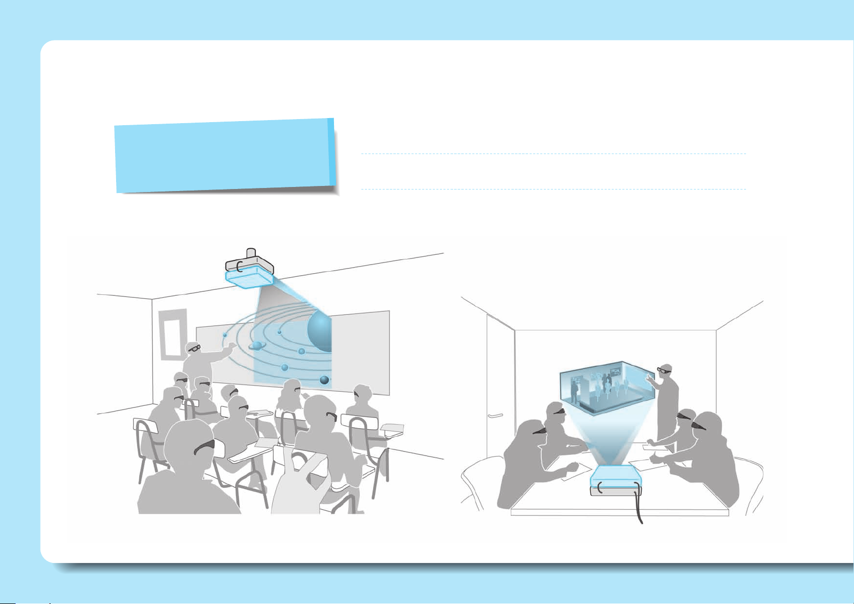
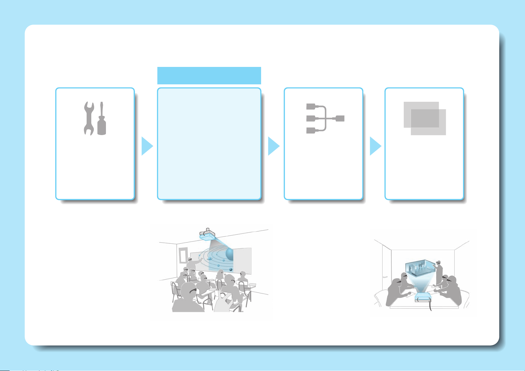
With This Projection System You Can...
Superimpose images from two stacked projectors to project a single
Stack Two Projectors
brighter, cleaner image.
Stack projection also allows projection of 3D images that can be viewed by
a large audience.
2
Page 3
in
L - out - R
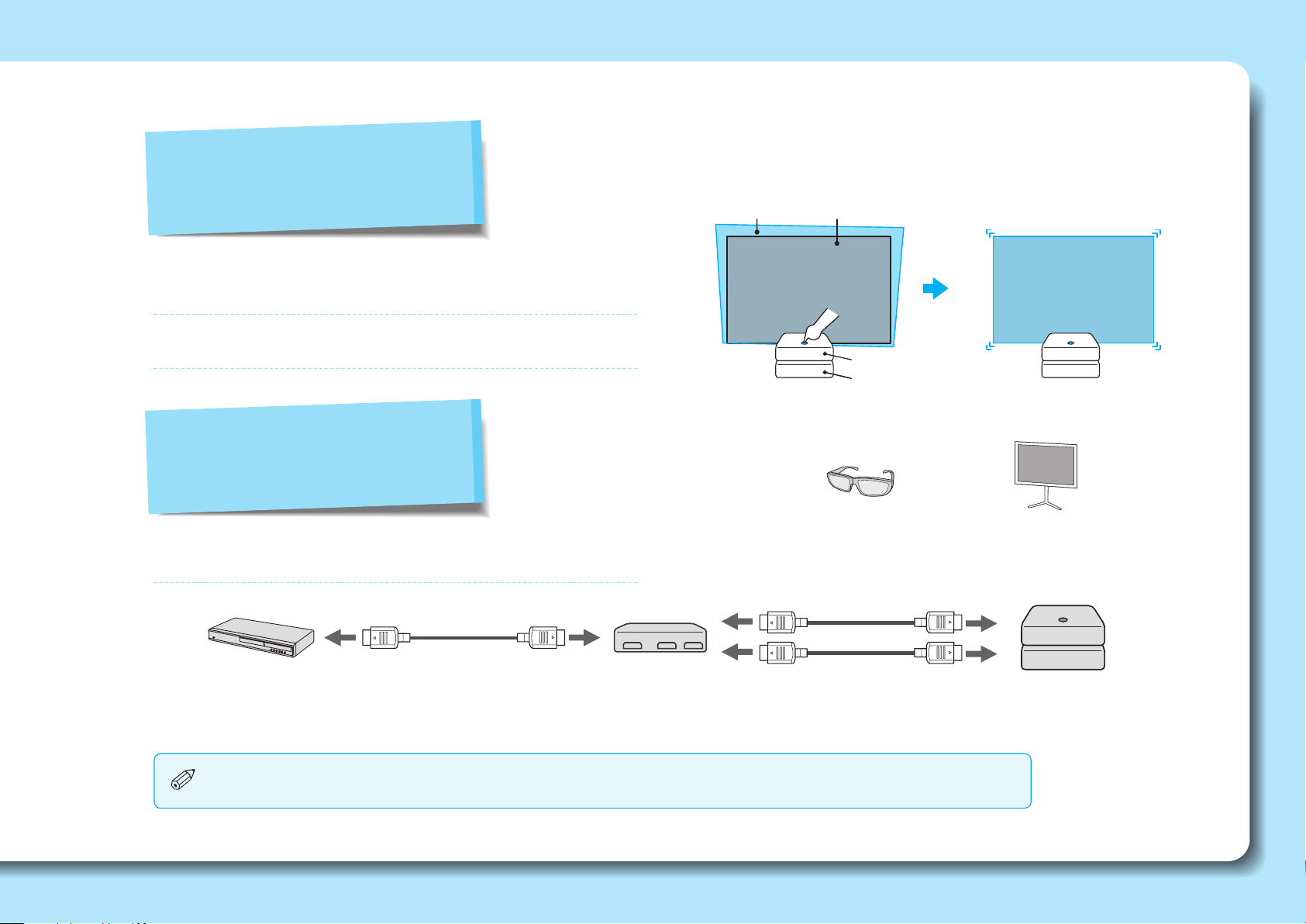
Easily Superimpose Two Images
This system comes equipped with a function that allows you
to easily superimpose two images.
See "Projecting Images" on page 14 for more information on
superimposing images.
Project 3D Images
Projected
commander
image
Projected
receiver
image
Commander
Receiver
Project stunning 3D content from media such as 3D Blu-ray™
discs or 3D games.
3D compatible device
(not included)
HDMI cable
(not included)
You may not need an HDMI splitter if your 3D compatible device is equipped with 2 HDMI outputs.
HDMI splitter that
supports 3D
(not included)
Passive 3D glasses
HDMI cables
(not included)
Silver screen with a
recommended gain of 2.3 - 2.7
(not included)
Projection system
3
Page 4
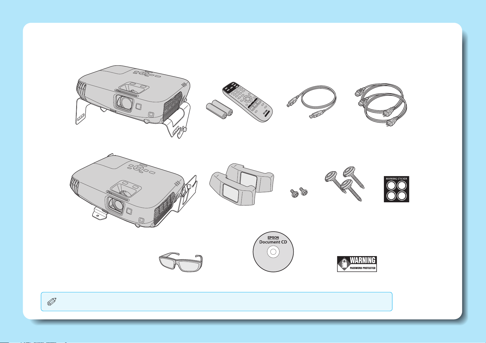
What's in the Box
Projector
and stacking mount
(commander)
AA batteries
(for remote control)
Remote control
USB cable Power cables (2)
M3 screws to secure
polarizing lters (2)
Adjustable
feet (3)
Password
Protected sticker
Marking
stickers
Projector
and stacking mount
(receiver)
Passive 3D glasses
(1 pair)
Polarizing lters (2)
Document CD
You can purchase additional glasses for children (part number V12H541B20) and adults (part number V12H541A20) through Epson.
4
Page 5
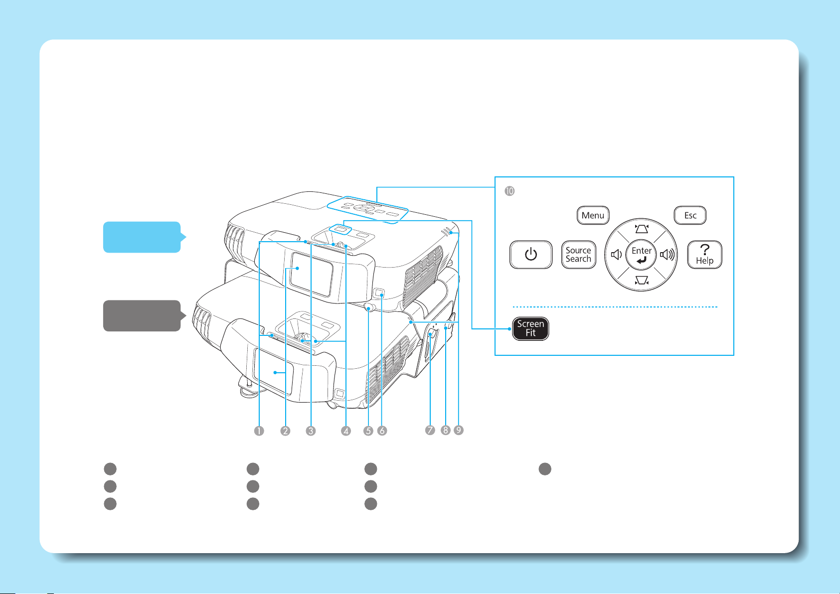
Part Names and Functions (Front/Top)
When two projectors are assembled in a stacked conguration, the projector on top is called the “Commander”, and the projector on the bottom is called the
“Receiver.” When suspended from a ceiling, the projector on top is the receiver, and the projector on the bottom is the commander.
The commander controls the receiver, and the projectors are linked together (with the included USB cable). You can operate both projectors at the same time
from the commander’s control panel.
Control panel
Commander
Receiver
1
A/V mute slide
2
Polarizing lter
3
Focus ring
4
Zoom ring
5
Remote receiver
6
Sensor
7
Stacking mount angle adjustment
8
Stacking mount connector
9
Indicators
10
Control panel
5
Page 6
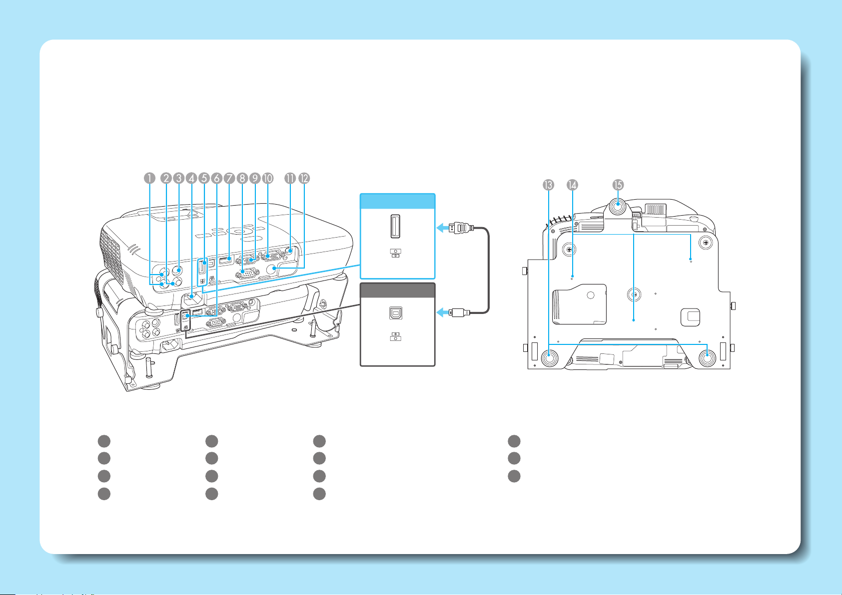
Part Names and Functions (Rear/Base)
Use the supplied USB cable to link the commander and the receiver.
Rear
This explanation of the rear uses the commander as an example.
1
Audio-L/R port
2
Video port
5
USB Type A port
6
USB Type B port
9
10
Commander
USB-A
Receiver
USB-B
Computer1 port
Monitor Out/Computer2 port
USB cable
Base
13
Rear adjustable feet
14
Ceiling mount attachment points (three points)
3
S-Video port
4
Power inlet
7
HDMI port
8
RS-232C port
11
Audio Out port
12
Remote receiver
15
Front adjustable foot
You cannot use the commander's USB-B port. Also, you cannot
use the receiver's USB-A port, RS-232C port, or the remote
receiver. See the online User's Guide for more information.
6
Page 7
Setup and Installation
For ceiling mount installation only
You need the optional ceiling
mount (part number ELPMBPJF)
when suspending the projectors
from a ceiling. See the User's Guide
supplied with the ceiling mount
for more information on attaching
and installing the ceiling mount.
Setting Up
p.8
Connecting
Equipment
p.10
This guide explains the following
connection methods. See
the online User's Guide for
information on other connection
methods.
Connecting to a computer
• Connecting with computer cables
• Connecting with HDMI cables
Connecting to video equipment
• Connecting with HDMI cables
Projecting
Images
p.14
7
Page 8
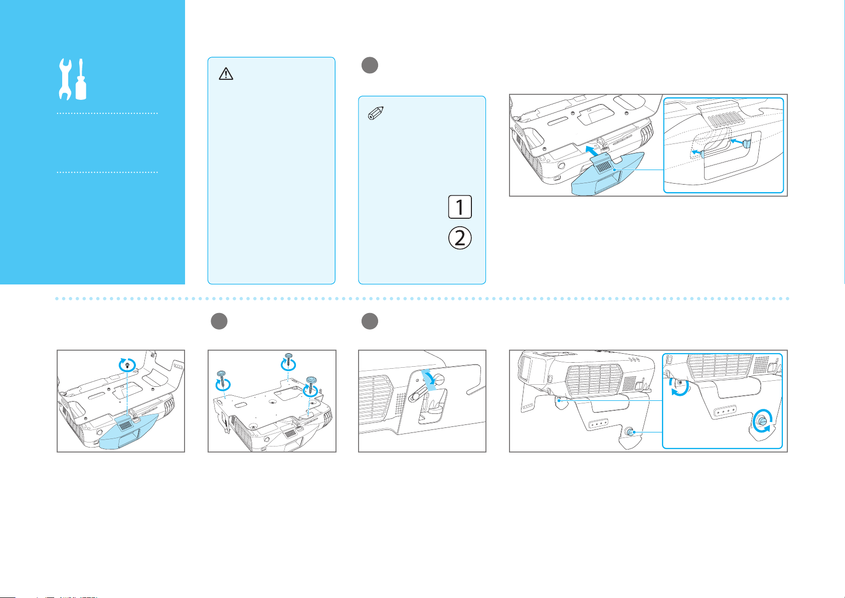
Setting Up
Stacking and
installing the
commander and the
receiver
Use the stacking
mounts to create a
stacked conguration
(one projector on top of
the other).
Warning
When assembling a
stacked conguration,
make sure you follow
these steps. If the
steps are not followed
correctly, the product
could fall, or your ngers
could get caught, which
could cause an injury.
Attach the polarizing lters to the commander and the receiver.
1
There are numbers
on the bases of
the projectors, stacking
mounts, and polarizing
lters. Make sure the
numbers match when
assembling.
Commander
Turn over the commander and the receiver, and then attach the polarizing
lters.
Press until they click into place.
Receiver
Secure the polarizing lters for
the commander and the receiver
with the supplied screws. Do not
overtighten the screws.
88888
Attach the feet (when
2
setting up on a desk).
Attach the front foot and the rear
feet to the base of the receiver.
Turn the feet to extend and
retract to adjust the horizontal
tilt.
Stack the commander on top of the receiver.
3
Carefully remove the protective
tape from the stack angle
adjustment screws, and then
remove the screws (on both the
left and right sides).
Loosen the screws for the commander's stacking mount connector (on
both the left and right sides).
Page 9

Caution
When attaching the
commander to the
receiver, be careful not to
trap your ngers.
Attach the commander to the receiver by sliding the commander’s
stacking mount screws into the slots in the receiver’s stacking mount.
Then lightly tighten the screws (on both the left and right sides) to secure
the attachment.
Secure the stacking mount angle adjustment with screws.
4
There are screw holes
numbered 1 to 4 on
the left and right of the
stacking mount.
You can change the
commander's projection
angle by changing the
position secured by the
screw.
See "Screen Size and
Projection Distance"
Place the screws into the holes, and then tighten them securely (on both
the left and right sides). Then tighten the commander's stacking mount
screws as well.
on page 18 to determine
which screw hole to use.
Place marking
stickers on the
positions where the
screws are secured. You
can then use these marks
when reassembling.
Remove the clear
5
protective lm from the
polarizing lters.
99999
Page 10
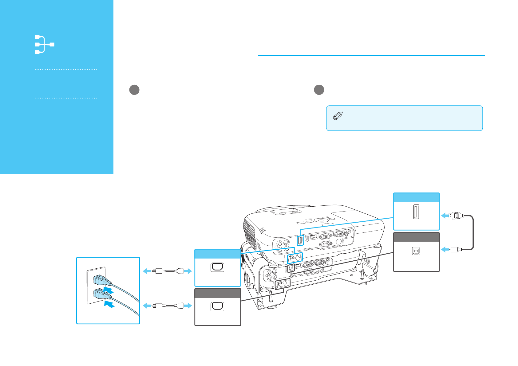
Connecting Equipment
Connecting the
commander and the
receiver
You need to connect
a USB cable to link the
commander and the
receiver.
First, connect the power cables and the USB cable.
Plug in the power cables for the commander and the
1
receiver.
Connect the commander's USB-A port to the receiver's
2
USB-B port with the supplied USB cable.
The projectors will not be linked if the wrong
USB ports are connected with the USB cable.
Commander
1010101010
Power cable
Power cable
Commander
Power inlet
Receiver
Power inlet
USB-A
Receiver
USB-B
USB cable
Page 11
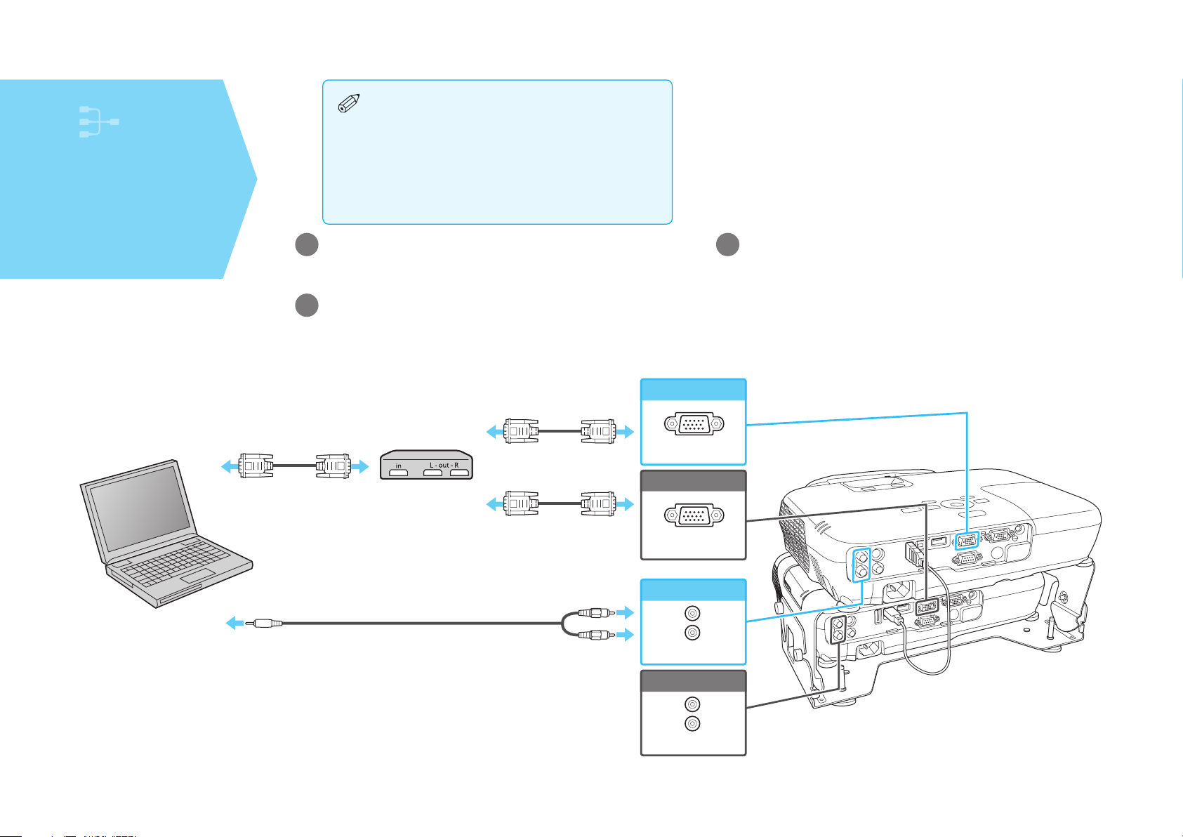
Connecting to a
computer
Connecting with
computer cables
First, check that the commander and the
•
receiver are properly connected with the
USB cable.
Next, obtain the following items (not included):
•
3 VGA cables
•
Audio cable (when outputting audio)
•
VGA splitter
•
Connect the splitter to the computer with a VGA cable.
1
Connect the commander and the receiver to the splitter
2
with VGA cables.
Commander
Connect the commander or receiver to the computer with
3
an audio cable.
Audio is output from the connected projector.
Computer cable
(not included)
VGA splitter
(not included)
Audio cable
(not included)
Computer cable
(not included)
Computer cable
(not included)
Computer1
Receiver
Computer1
Commander
Audio-L/R
Receiver
Audio-L/R
1111111111
Page 12
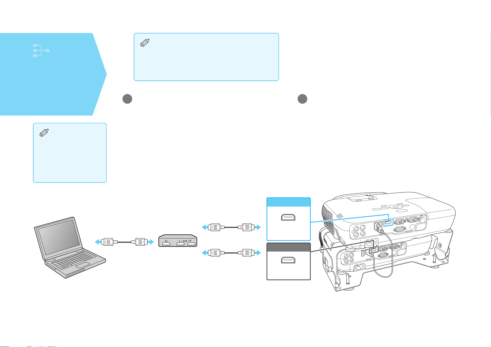
Connecting to a
computer
Connecting with HDMI
cables
When viewing 3D
images, make sure you
use HDMI cables and
an HDMI splitter that
support 3D signals.
First, check that the commander and the
•
receiver are properly connected with the
USB cable.
Next, obtain the following items (not included):
•
3 HDMI cables
•
HDMI splitter
•
Connect the splitter to the computer with an HDMI cable.
1
Commander
Connect the commander and the receiver to the splitter
2
with HDMI cables.
You can send the computer's audio with the projected image.
1212121212
HDMI cable
(not included)
HDMI
splitter
(not included)
HDMI cable
(not included)
HDMI cable
(not included)
HDMI
Receiver
HDMI
Page 13
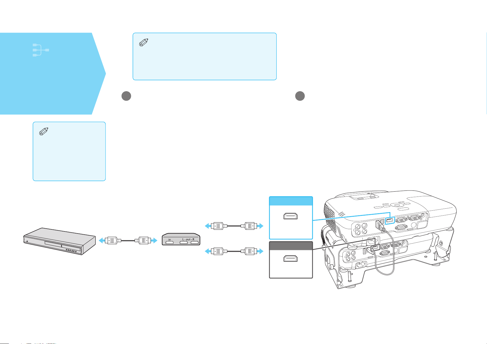
Connecting to
video equipment
Connecting with HDMI
cables
When viewing 3D
images, make sure you
use HDMI cables and
an HDMI splitter that
support 3D signals.
First, check that the commander and the
•
receiver are properly connected with the
USB cable.
Next, obtain the following items (not included):
•
3 HDMI cables
•
HDMI splitter
•
Connect the splitter to the video equipment with an HDMI
1
cable.
Commander
Connect the commander and the receiver to the splitter
2
with HDMI cables.
You can send the computer's audio with the projected image.
HDMI cable
(not included)
HDMI
splitter
(not included)
HDMI cable
(not included)
HDMI cable
(not included)
HDMI
Receiver
HDMI
1313131313
Page 14
Projecting Images
Superimposing the
images from the
commander and the
receiver
Perform this procedure
after setting up the
projectors.
When suspending
the projectors from
a ceiling, change the
Projection mode before
superimposing the
images. You can change
the Projection mode by
holding down the [A/V
Mute] button on the
remote control for about
ve seconds.
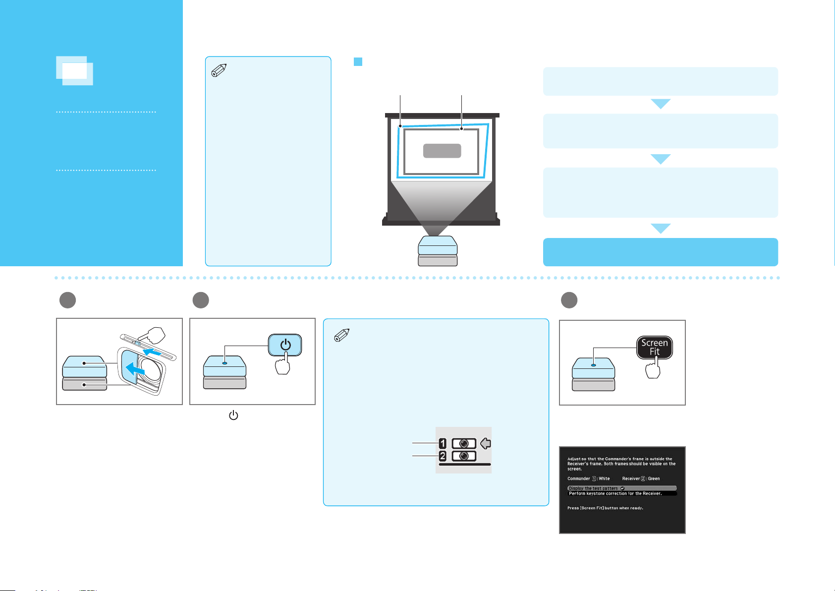
Superimposing Images
Commander frame
(white)
Receiver frame
(green)
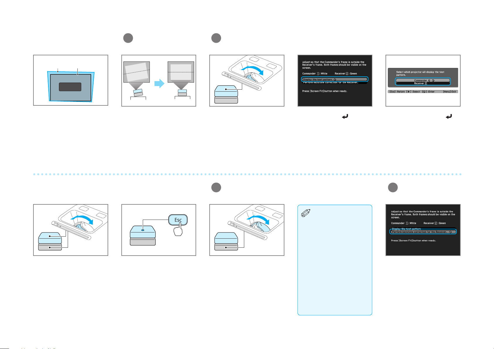
Adjust the focus for the commander and receiver.
Size the receiver's frame.
Adjust the receiver's projection size to t the screen.
Surround the receiver's frame with the commander's
frame.
Adjust the commander's frame (white) so that it is outside the
receiver's frame (green).
Superimpose the images.
Open the A/V mute
1
slides.
Open the A/V mute slides on the
commander and the receiver.
1414141414
Turn on the projectors.
2
Press the [ ] button on the
commander's control panel.
The commander and the receiver
turn on.
The commander's control panel operates
•
both the commander and the receiver.
Perform projector operations from the
commander's control panel.
The following icon is displayed when
•
turning the projector system on. The
projector indicated by the arrow is the
subject of any displayed status message.
Commander
Receiver
Display the adjustment screen
3
for the superimposed images.
Approx.
ve seconds
Hold down the [Screen Fit] button for about ve seconds.
The initial adjustment screen and the white and green
frames are displayed.
Page 15
Adjust the projection
4
position.
Adjust the focus for the commander and the receiver.
5
Commander
frame
The white frame is used to adjust
the commander, and the green
frame is used to adjust the
receiver.
Use the focus ring on the
projector you want to adjust.
When you have nished
correcting the focus, press the
[Esc] button.
Next, select the other projector
from the test pattern menu and
repeat the focus adjustment
procedure described above.
Receiver
frame
If the projection system is on a
desk, extend or retract the feet to
adjust the position. The rear feet
adjust the horizontal tilt and the
front foot adjusts the height.
If the system is suspended from
a ceiling, see the User's Guide
supplied with the ceiling mount.
When you have nished
correcting the focus for the
commander and the receiver,
press the [Esc] button until you
see the initial adjustment screen
again.
Use the commander's focus
ring to adjust the focus for the
projected image.
Adjust the projection size for the receiver.
6
Use the receiver's zoom ring
to adjust the receiver's frame
(green) to the projection size
you want.
Select Display the test pattern,
and then press the [ ] button.
Do not maximize the
zoom for the receiver
because the commander's
frame needs to be larger
than the receiver's frame.
See "Screen Size and
Projection Distance" on
page 18 to determine the
projection size.
Select the projector you want to
adjust, and then press the [ ]
button.
The test pattern is displayed.
Correct keystone
7
distortion for the
receiver's frame (green).
Select Perform keystone
correction for the Receiver.
Next, use either the
H/V - keystone or Quick Corner®
method as described on the
next page.
1515151515
Page 16

Correcting using
H/V-Keystone
Correct keystone distortion for the receiver's frame (green).
Correcting using
Quick Corner
Correct the four corners of the receiver's
frame (green) individually.
Select H/V-Keystone.
Use the [ ] [ ] [ ] [ ]
buttons to select the corner you
want to correct, and then press
the [ ] button.
Use the [ ] [ ] buttons to
select the direction you want
to correct, and then press the
[ ] [ ] buttons to make
corrections.
Use the [ ] [ ] [ ] [ ]
buttons to correct the position of
the corners.
Correct each corner as necessary.
Press the [Esc] button to nish
making settings.
When you have nished making
corrections, press the [Esc]
button until you see the initial
adjustment screen again.
Press the [Esc] button to nish
making settings.
When you have nished making
corrections, press the [Esc]
button until you see the initial
adjustment screen again.
correction for the Receiver.
Adjust the projection size for the commander's frame
8
(white).
Commander
frame
Receiver
frame
For best results, minimize the
•
dierence in size between
the receiver's frame (green)
and the commander's frame
(white).
The images can still be
•
superimposed even if the
Use the commander's zoom ring
to adjust the commander's frame
(white) so that it is outside the
receiver's frame (green).
commander's frame is outside
the screen.
If you have trouble adjusting
•
the frames, make sure you
selected the correct screw hole
when you adjusted the angle
between the projectors. See
“Screen Size and Projection
Distance” on page 18 to
determine which screw hole
to use.
Select Quick Corner.Select Perform keystone
1616161616
Page 17

Superimpose two images.
9
If you need to ne tune
the superimposed
images
Adjust both projected
1
images manually.
Press the [Screen Fit] button. The images from the
commander and the receiver are
automatically superimposed.
Correct the four corners individually.
2
When adjusting
each corner individually,
adjust so that the white
and green patterns
overlap to create one
pattern.
The white pattern is for adjusting
the commander, and the green
pattern is for adjusting the
receiver.
If you need to make ne
adjustments, see the next
section.
If you have nished making
adjustments, select No, and then
press the [ ] button.
Use the [ ] [ ] [ ] [ ]
buttons to select the corner you
want to correct, and then press
the [ ] button.
Use the [ ] [ ] [ ] [ ]
buttons to correct the position of
the corners.
Correct each corner as necessary.
If you need to make ne
adjustments, select Yes, and then
press the [ ] button.
The manual adjustment screen is
displayed.
Press the [Esc] button to nish
making settings.
1717171717
Page 18

Screen Size and Projection Distance
Projection distance
1
Distance from the center of the receiver's
2
lens to the base of the screen (or to top of
the screen, if suspended from a ceiling)
Center of receiver's lens
3
Screw hole numbers (for angle adjustment)
4
Range for superimposing two images
Silver screen (for viewing 3D images)•
Screen Size
Up to 120”
Other projection surfaces (for viewing 2D images)•
Screen Size
97”-181” (248-461 cm)
5
Approx. 10° maximum Approx. 10° maximum
5 6 7
Distance from projector to
5
screen
Horizontal angle
6
Vertical angle
7
6 7
18
When viewing 3D images, you can use screen sizes up to 120”.
4:3
Screen
Size
80” 110”-121” (281-306 cm) 4.3” (11 cm) 4
90” 124”-136” (316-345 cm) 4.8” (12 cm)
100” 138”-151” (351-383 cm) 5.4” (14 cm)
110” 152”-166” (387-422 cm) 5.9” (15 cm)
120” 166”-181” (422-461 cm) 6.4” (16 cm)
130” 180”-197” (458-499 cm) 7” (18 cm)
140” 194”-212” (493-538 cm) 7.5” (19 cm)
150” 208”-227” (529-577 cm) 8” (20 cm)
Minimum to Maximum
Conversion gures in these tables may have been rounded up or down.
1
2 4
3
2
1
Up to 150”50”0”
16:9
Screen
Size
80” 100”-109” (255-278 cm) 1.7” (4 cm)
90” 113”-123” (287-313 cm) 1.9” (5 cm)
100” 125”-137” (319-348 cm) 2.1” (5 cm)
110” 138”-151” (351-383 cm) 2.4” (6 cm)
120” 151”-165” (383-418 cm) 2.6” (7 cm)
130” 163”-178” (415-453 cm) 2.8” (7 cm)
140” 176”-192” (447-488 cm) 3” (8 cm)
150” 189”-206” (479-523 cm) 3.2” (8 cm)
Minimum to Maximum
1
2 4
97”-227” (248-577 cm)
16:10
Screen
Size
4
3
2
1
80” 97”-106” (248-270 cm) 3.8” (10 cm)
90” 110”-120” (279-304 cm) 4.3” (11 cm)
100” 122”-133” (310-338 cm) 4.7” (12 cm)
110” 134”-147” (341-372 cm) 5.2” (13 cm)
120” 147”-160” (373-407 cm) 5.7” (14 cm)
130” 159”-174” (404-441 cm) 6.2” (16 cm)
140” 171”-187” (435-475 cm) 6.6” (17 cm)
150” 184”-200” (467-509 cm) 7.1” (18 cm)
Approx.15° maximum Approx.15° maximum
1
Minimum to Maximum
2 4
4
3
2
1
Page 19

About the LED Indicators
The LED indicators change according to the status of the commander and the receiver. For more troubleshooting information, see your online User's Guide.
On Flashing O
Indicator status during normal operation
Orange
Green
Green
Standby
Warm-up in progress
Projection in
progress
Indicator status during an error/warning
Red
Red
Red
Red
Red
Red
Red
Red
Orange
Internal Error
Fan Error
Sensor Error
High Temp Error
Wait for about ve
minutes, and then
disconnect the power
cable from the electrical
outlet.
High Temp Warning
Press to start projection.
is unavailable for about 30 seconds.
The projector is operating normally.
Disconnect the power cable from the electrical
outlet, and contact Epson.
Check the following points.
If the projectors are positioned next to a wall,
•
move them farther away from the wall.
Clean or replace the air lter.
•
Make sure nothing is blocking the vents.
•
Red
Red
Orange
Red
Red
Red
Lamp Error
Lamp Failure
Replace Lamp
Auto Iris Error
Power Error
Check the following points.
Remove the lamp and check that it is not
•
damaged. If it is not damaged, reinstall the
lamp and turn on the projector. If it is damaged,
contact Epson.
Check that the lamp and the lamp cover are
•
securely installed.
Clean the air lter.
•
Replace the lamp as soon as possible. The lamp
may fail if you continue to use it in this condition.
Disconnect the power cable from the electrical
outlet, and contact Epson.Epson..
If the error continues to occur after checking the points above, disconnect the power cable from
the electrical outlet, and contact
Epson
.
19
Page 20

Troubleshooting
You can’t get the adjustment screen with the white and green frames to display.
Make sure you press and hold the [Screen Fit] button for at least 5 seconds. Do not release the [Screen Fit] button until you see the frames.
You see a Screen Fit has not been executed completely message while you are trying to start the Screen Fit process.
Press the [ ] button to clear the error, then press and hold the [Screen Fit] button (for at least 5 seconds) until you see the white and green frames on the screen. Do not
release the [Screen Fit] button until you see the frames.
The Receiver does not turn on when you turn on the Commander.
Make sure the USB cable is properly connected.
Where to get help
Manual
For more information about using the projector, click the icon on your desktop to access the online manual (requires an Internet connection). If you don’t have a User’s Guide
icon, you can install it from the projector CD or go to the Epson website, as described below.
Telephone support services
To use the EPSON® PrivateLine® Support service, call (800) 637-7661. This service is available 6 AM to 8 PM, Pacific Time, Monday through Friday, for the duration of your warranty
period.
You may also speak with a support specialist by calling (562) 276-4394 (U.S.) or (905) 709-3839 (Canada), 6 AM to 8 PM, Pacific Time, Monday through Friday, and 7 AM to 4 PM,
Pacific Time, Saturday.
Days and hours of support are subject to change without notice. Toll or long distance charges may apply.
Internet support
Visit www.epson.com/support (U.S.) or www.epson.ca/support (Canada) for solutions to common problems. You can download utilities and documentation, get FAQs and
troubleshooting advice, or e-mail Epson.
Registration
Register today to get product updates, special promotions, and customer-only offers. You can use the CD included with your projector or register online at
www.epson.com/webreg.
20
Page 21

Notices
Declaration of Conformity
According to 47CFR, Part 2 and 15, Class B Personal Computers and Peripherals; and/or CPU Boards and Power Supplies used with Class B Personal Computers
We: Epson America, Inc.
Located at: 3840 Kilroy Airport Way
MS: 3-13
Long Beach, CA 90806
Tel: 562-981-3840
Declare under sole responsibility that the product identified herein, complies with 47CFR Part 2 and 15 of the FCC rules as a Class B digital device. Each product marketed,
is identical to the representative unit tested and found to be compliant with the standards. Records maintained continue to reflect the equipment being produced can be
expected to be within the variation accepted, due to quantity production and testing on a statistical basis as required by 47CFR 2.909. Operation is subject to the following
two conditions: (1) this device may not cause harmful interference, and (2) this device must accept any interference received, including interference that may cause
undesired operation.
Trade Name: EPSON
Type of Product: LCD Projector
Model: H494A
Marketing Name: PowerLite W16SK
FCC Compliance Statement (PowerLite W16SK stacked configuration)
For United States Users
This equipment has been tested and found to comply with the limits for a Class A digital device, pursuant to Part 15 of the FCC Rules. These limits are designed to provide
reasonable protection against harmful interference when the equipment is operated in a commercial environment. This equipment generates, uses, and can radiate radio
frequency energy and, if not installed and used in accordance with the instruction manual, may cause harmful interference to radio communications. Operation of this
equipment in a residential area is likely to cause harmful interference in which case the user will be required to correct the interference at his own expense.
For Canadian Users
This Class A digital apparatus complies with Canadian ICES-003.
Cet appareil numérique de la classe A est conforme à la norme NMB-003 du Canada.
FCC Compliance Statement (PowerLite W16SK single configuration)
For United States Users
This equipment has been tested and found to comply with the limits for a Class B digital device, pursuant to Part 15 of the FCC Rules. These limits are designed to provide
reasonable protection against harmful interference in a residential installation. This equipment generates, uses, and can radiate radio frequency energy and, if not installed
and used in accordance with the instructions, may cause harmful interference to radio communications. However, there is no guarantee that interference will not occur in a
particular installation. If this equipment does cause interference to radio and television reception, which can be determined by turning the equipment off and on, the user is
encouraged to try to correct the interference by one or more of the following measures.
• Reorient or relocate the receiving antenna.
• Increase the separation between the equipment and receiver.
21
Page 22

• Connect the equipment into an outlet on a circuit different from that to which the receiver is connected.
• Consult the dealer or an experienced radio/TV technician for help.
WARNING
The connection of a non-shielded equipment interface cable to this equipment will invalidate the FCC Certification or Declaration of this device and may cause interference
levels which exceed the limits established by the FCC for this equipment. It is the responsibility of the user to obtain and use a shielded equipment interface cable with this
device. If this equipment has more than one interface connector, do not leave cables connected to unused interfaces. Changes or modifications not expressly approved by
the manufacturer could void the user’s authority to operate the equipment.
For Canadian Users
This Class B digital apparatus complies with Canadian ICES-003.
Cet appareil numérique de la classe B est conforme à la norme NMB-003 du Canada.
Epson America, Inc. Limited Warranty
Two-Year Projector Limited Warranty, 90-Day Lamp Limited Warranty and 90-Day Passive 3D Glasses Limited Warranty
What Is Covered: Epson America, Inc. (“Epson”) warrants to the original retail purchaser of the EPSON projector product enclosed with this limited warranty statement that
the product, if purchased new and operated in the United States, Canada, or Puerto Rico will be free from defects in workmanship and materials for a period of two (2) years
from the date of original purchase. This limited warranty applies only to the projector and not to the projector lamp or passive 3D glasses. The projector lamp carries a limited
warranty period of ninety (90) days from the date of original purchase. The passive 3D glasses carry a limited warranty period of ninety (90) days from the date of original
purchase. For warranty service, you must provide proof of the date of original purchase.
What Epson Will Do To Correct Problems: If your product requires service during the limited warranty period, please call Epson at the number on the bottom of this statement
and be prepared to provide the model, serial number, and date of original purchase. Epson will, at its option, repair or replace the defective unit, without charge for parts
or labor. If Epson authorizes an exchange for the defective projector, Epson will ship a replacement projector to you, freight prepaid, so long as you use an address in the
United States, Canada, or Puerto Rico. You are responsible for securely packaging the defective unit and returning it to Epson within five (5) working days of receipt of
the replacement. Epson requires a debit or a credit card number to secure the cost of a replacement projector in the event that you fail to return the defective one. When
Epson authorizes an exchange for defective 3D glasses, you must first send in the defective glasses to Epson. Once we have received your defective glasses Epson will ship
a replacement product to you, freight prepaid, so long as you use an address in the United States, Canada, or Puerto Rico. If Epson authorizes repair instead of exchange,
Epson will direct you to send your product to Epson or its authorized service center, where the product will be repaired and sent back to you. You are responsible for
packing the product and for all costs to and from the EPSON authorized service center. When warranty service involves the exchange of the product or of a part, the item
replaced becomes Epson property. The exchanged product or part may be new or refurbished to the Epson standard of quality, and at Epson’s option, the replacement may
be another model of like kind and quality. Epson’s liability for replacement of the covered product will not exceed the original retail selling price of the covered product.
Exchange or replacement products or parts assume the remaining warranty period of the product covered by this limited warranty. If Epson replaces the lamp as part of the
warranty service, the replacement lamp carries the limited 90-day warranty stated above.
What This Warranty Does Not Cover: This warranty covers only normal use in the United States, Canada or Puerto Rico. Twenty-four hours per day or other excessive continual
use is not considered normal use. This warranty does not cover consumables such as filters. This warranty is not transferable. Epson is not responsible for warranty service
should the Epson label or logo or the rating label or serial number be removed. Epson is not responsible for warranty service should the product fail to be properly
maintained or fail to function properly as a result of misuse, abuse, improper installation, neglect, improper shipping, damage caused by disasters such as fire, flood, and
lightning, improper electrical current, software problems, interaction with non-EPSON products, or service other than by Epson or an EPSON Authorized Servicer. Postage,
insurance, or shipping costs incurred in presenting your EPSON product for carry-in warranty service are your responsibility. Epson will pay for all freight charges if you
choose to send your unit to Epson for repair. If a claimed defect cannot be identified or reproduced in service, you will be held responsible for costs incurred.
2222
Page 23

THE WARRANTY AND REMEDY PROVIDED ABOVE ARE EXCLUSIVE AND IN LIEU OF ALL OTHER EXPRESS OR IMPLIED WARRANTIES INCLUDING, BUT NOT LIMITED TO, THE
IMPLIED WARRANTIES OF MERCHANTABILITY OR FITNESS FOR A PARTICULAR PURPOSE. SOME LAWS DO NOT ALLOW THE EXCLUSION OF IMPLIED WARRANTIES. IF THESE
LAWS APPLY, THEN ALL EXPRESS AND IMPLIED WARRANTIES ARE LIMITED TO THE WARRANTY PERIOD IDENTIFIED ABOVE. UNLESS STATED HEREIN, ANY STATEMENTS OR
REPRESENTATIONS MADE BY ANY OTHER PERSON OR FIRM ARE VOID. IN THE EVENT THE REMEDIES ABOVE FAIL, EPSON’S ENTIRE LIABILITY SHALL BE LIMITED TO A REFUND
OF THE PRICE PAID FOR THE EPSON PRODUCT COVERED BY THIS LIMITED WARRANTY. EXCEPT AS PROVIDED IN THIS WRITTEN WARRANTY, NEITHER EPSON AMERICA, INC.
NOR ITS AFFILIATES SHALL BE LIABLE FOR ANY LOSS, INCONVENIENCE, OR DAMAGE, INCLUDING DIRECT, SPECIAL, INCIDENTAL, OR CONSEQUENTIAL DAMAGES, RESULTING
FROM THE USE OR INABILITY TO USE THE EPSON PRODUCT, WHETHER RESULTING FROM BREACH OF WARRANTY OR ANY OTHER LEGAL THEORY.
In Canada, warranties include both warranties and conditions.
Some jurisdictions do not allow limitations on how long an implied warranty lasts and some jurisdictions do not allow the exclusion or limitation of incidental or
consequential damages, so the above limitations and exclusions may not apply to you. This warranty gives you specific legal rights, and you may also have other rights,
which vary from jurisdiction to jurisdiction.
To find the EPSON Authorized Reseller nearest you, please visit our website at: www.epson.com.
To find the EPSON Customer Care Center nearest you, please visit www.epson.com/support.
To contact the EPSON ConnectionSM, please call (800) 637-7661 or (562) 276-4394 in the U.S. and (905) 709-3839 in Canada or write to Epson America, Inc., P.O. Box 93012,
Long Beach, CA 90809-3012.
Copyright Notice
All rights reserved. No part of this publication may be reproduced, stored in a retrieval system, or transmitted in any form or by any means, electronic, mechanical,
photocopying, recording, or otherwise, without the prior written permission of Seiko Epson Corporation. No patent liability is assumed with respect to the use of the
information contained herein. Neither is any liability assumed for damages resulting from the use of the information contained herein.
Neither Seiko Epson Corporation nor its affiliates shall be liable to the purchaser of this product or third parties for damages, losses, costs, or expenses incurred by the
purchaser or third parties as a result of: accident, misuse, or abuse of this product or unauthorized modifications, repairs, or alterations to this product, or (excluding the U.S.)
failure to strictly comply with Seiko Epson Corporation’s operating and maintenance instructions.
Seiko Epson Corporation shall not be liable against any damages or problems arising from the use of any options or any consumable products other than those designated
as Original EPSON Products or Epson Approved Products by Seiko Epson Corporation.
Trademarks
EPSON, PowerLite, and Quick Corner are registered trademarks, and EPSON Exceed Your Vision is a registered logomark of Seiko Epson Corporation.
PrivateLine is a registered trademark and EPSON Connection is a service mark of Epson America, Inc.
General Notice: Other product names used herein are for identification purposes only and may be trademarks of their respective owners. Epson disclaims any and all rights in
those marks.
This information is subject to change without notice.
© 2012 Epson America, Inc. 9/12
23
23
Page 24

Avec ce projecteur vous pouvez...
Superposer des images de deux projecteurs diérents pour les fusionner en
une seule image plus nette et plus lumineuse.
Empiler deux projecteurs
La projection empilée permet aussi de projeter des images 3D qui peuvent
être vues par un large public.
24
Page 25

in
L - out - R
Superposer facilement deux images
Cet appareil est équipé d’une fonction qui vous permet de
superposer facilement deux images.
Consultez la section « Projection d’images » à la page 36 pour
plus d’informations sur la superposition des images.
Projeter des images 3D
Image
projetée du
contrôleur
Image
projetée du
récepteur
Contrôleur
Récepteur
Lunettes 3D passives
Projetez du contenu 3D éblouissant provenant de supports
tels que des disques Blu-rayMC 3D ou des jeux vidéo 3D
Appareil 3D compatible
(non inclus)
Câble HDMI
(non inclus)
Répartiteur HDMI
prenant en charge le mode 3D
(non inclus)
Il est possible que vous n’ayez pas besoin d’un répartiteur HDMI si votre appareil compatible 3D est muni de 2 sorties HDMI.
Câbles HDMI
(non inclus)
Grand écran avec un gain
recommandé de 2,3 - 2,7
(non inclus)
Système de projection
25
25
Page 26

Contenu de l’emballage
Projecteur et
support d’empilage
(contrôleur)
Piles AA (pour la
télécommande)
Télécommande
Câble USB Câbles d’alimentation (2)
26
Vis M3 pour xer les
filtres polariseurs (2)
Pieds réglables (3) Autocollants
de marquage
Autocollant de protection
du mot de passe
Projecteur et
support d’empilage
(récepteur)
Lunettes 3D
passives (1 paire)
Filtres polariseurs (2)
CD de documentation
Vous pouvez acheter des lunettes additionnelles pour enfants (numéro de produit V12H541B20) et pour adultes (numéro de produit V12H541A20) chez Epson.
Page 27

Noms et fonctions des pièces (avant/dessus)
Lorsque deux projecteurs sont assemblés dans une conguration empilée, le projecteur sur le dessus est appelé le « contrôleur », et le projecteur du dessous est
appelé le « récepteur ». Lorsqu’ils sont suspendus au plafond, le projecteur du dessus est le récepteur, et le projecteur du dessous est le contrôleur.
Le contrôleur contrôle le récepteur, et les projecteurs sont reliés entre eux (à l’aide du câble USB inclus). Vous pouvez utiliser les deux projecteurs en même
temps à partir du panneau de commande du contrôleur.
Panneau de commande
Contrôleur
Récepteur
1
Curseur de pause A/V
2
Filtre polariseur
3
Bague de mise au point
4
Bague de zoom
5
Récepteur de la télécommande
6
Capteur
7
Régleur de l’angle du support d’empilage
8
Connecteur de support d’empilage
9
Témoins
10
Panneau de commande
27
Page 28

Noms et fonctions des pièces (arrière/dessous)
Utilisez le câble USB fourni pour relier le contrôleur et le récepteur.
Dessous
Cette explication de l’arrière utilise le contrôleur à titre d’exemple.
1
Port Audio-L/R
2
Port Video
5
Port USB Type A
6
Port USB Type B
9
Port Computer1
10
Port Monitor Out/Computer2
Contrôleur
USB-A
Récepteur
USB-B
Câble USB
Arrière
13
Pattes arrière réglables
14
Points d’installation du support au plafond (trois points)
28
3
Port S-Video
4
Entrée d’alimentation
7
Port HDMI
8
Port RS-232C
11
Port Audio Out
12
Récepteur de la télécommande
15
Patte avant réglable
Vous ne pouvez pas utiliser le port USB-B du contrôleur. Vous ne
pouvez pas non plus utiliser le port USB-A, le port RS-232C ou le
récepteur de la télécommande du récepteur. Consultez le Guide
de l’utilisateur en ligne pour plus d’informations.
Page 29

Conguration et installation
Pour une installation au plafond seulement
Vous avez besoin du support
d’installation au plafond
optionnel (numéro de produit
ELPMBPJF) si vous souhaitez
suspendre les projecteurs au
plafond. Consultez le Guide de
l’utilisateur fourni avec le support
Installation
p. 30
d’installation au plafond pour
plus d’informations sur la xation
et l’installation du support
d’installation au plafond.
Connexion de
l’équipement
p. 32
Ce guide explique les méthodes
de connexion suivantes.
Consultez le Guide de l’utilisateur
en ligne pour plus d’informations
sur les autres méthodes de
connexion.
Projection
d’images
p. 36
Connexion à un ordinateur
• Connexion avec des câbles
d’ordinateur
• Connexion avec des câbles HDMI
Connexion à un appareil vidéo
• Connexion avec des câbles HDMI
29
Page 30

Installation
Empiler et installer
le contrôleur et le
récepteur
Utilisez les supports
d’empilage pour créer
une conguration
empilée (un projecteur
au-dessus de l’autre).
Avertissement
Lors de l’assemblage
de projecteurs empilés,
assurez-vous de suivre les
étapes suivantes. Si vous
ne suivez pas les étapes
correctement, le produit
pourrait tomber, ou vous
pourriez vous coincer les
doigts, ce qui pourrait
causer des blessures.
Fixez les filtres polariseurs sur le contrôleur et le récepteur.
1
Des numéros se
trouvent sous les
projecteurs, les supports
d’installation et les
polariseurs. Assurezvous que les numéros
correspondent lors de
l’assemblage.
Contrôleur
Retournez le contrôleur et le récepteur et xez les filtres polariseurs.
Appuyez sur les filtres polariseurs jusqu’à ce qu’un déclic se fasse
entendre.
Récepteur
Fixez les filtres polariseurs sur le
contrôleur et le récepteur à l’aide
des vis incluses. Ne serrez pas
trop les vis.
3030303030
Fixez les pieds (si vous
2
comptez installer
les projecteurs sur
un bureau).
Fixez le pied avant et les pieds
arrière sous le récepteur. Tournez
les pieds pour les déployer
ou les rétracter an d’ajuster
l’inclinaison horizontale.
Placez le contrôleur sur le récepteur.
3
Retirez délicatement le ruban de
protection des vis de réglage de
l’angle du support, puis retirez les
vis (sur la gauche et la droite).
Desserrez les vis du connecteur du support d’empilage (sur la gauche et
sur la droite).
Page 31

Mise en garde
Lorsque vous xez le
contrôleur au récepteur,
veillez à ne pas vous
coincer les doigts.
Fixez le contrôleur sur le récepteur en glissant les vis du support
d’empilage du contrôleur dans les fentes du support d’empilage du
récepteur. Puis, serrez légèrement les vis (à la gauche et à la droite).
Fixez le réglage de l’angle du support avec les vis.
4
Les trous de vis sont
numérotés de 1 à 4 sur
la gauche et la droite
du support d’empilage.
Vous pouvez modier
l’angle de projection du
contrôleur en changeant
la position xée par la vis.
Consultez la section
Placez les vis dans les trous et serrez-les bien (sur la gauche et sur
la droite). Puis, serrez aussi les vis du support d’empilage du contrôleur.
« Taille de l’écran
et distance de
projection » à la page 40
pour déterminer quel
trou de vis utiliser.
Collez un autocollant
de marquage sur
les positions où les vis
sont xées. Vous pourrez
ensuite utiliser ces
marques lorsque vous
réassemblerez le support.
Retirez le film protecteur
5
sur les filtres polariseurs.
3131313131
Page 32

Connexion de l’équipement
Connecter le
contrôleur et le
récepteur
Vous devez utiliser le
câble USB fourni pour
relier le contrôleur et le
récepteur.
Connectez d’abord les câbles d’alimentation et le câble USB.
Branchez les câbles d’alimentation au contrôleur et au
1
récepteur.
Connectez le port USB-A du contrôleur au port USB-B du
2
récepteur avec le câble USB fourni.
Les projecteurs ne seront pas reliés si les mauvais
ports USB sont connectés avec le câble USB.
Contrôleur
3232323232
Câble d’alimentation
Câble d’alimentation
Contrôleur
Entrée
d’alimentation
Récepteur
Entrée
d’alimentation
USB-A
Récepteur
USB-B
Câble USB
Page 33

Connexion à un
ordinateur
Connexion avec des
câbles d’ordinateur
Tout d’abord, assurez-vous que le contrôleur et le récepteur
•
sont connectés correctement avec le câble USB.
Puis, procurez-vous les produits suivants (non inclus) :
•
3 câbles VGA
•
Câble audio (lorsque vous émettez du son)
•
Répartiteur VGA
•
Connectez le répartiteur à votre ordinateur à l’aide d’un
1
câble VGA.
Connectez le contrôleur et le récepteur au répartiteur avec
2
des câbles VGA.
Contrôleur
Connectez le contrôleur ou le récepteur à l’ordinateur à
3
l’aide d’un câble audio.
Le son est émis du projecteur connecté.
Câble de l’ordinateur
(non inclus)
Répartiteur VGA
(non inclus)
Câble audio
(non inclus)
Câble de l’ordinateur
(non inclus)
Câble de l’ordinateur
(non inclus)
Computer1
Récepteur
Computer1
Contrôleur
Audio-L/R
Récepteur
Audio-L/R
3333333333
Page 34

Connexion à un
ordinateur
Connexion avec des
câbles HDMI
Lorsque vous
projetez des images
3D, assurez-vous
d’utiliser des câbles
HDMI et un répartiteur
HDMI compatibles
avec le signal 3D.
Tout d’abord, assurez-vous que le contrôleur
•
et le récepteur sont connectés correctement
avec le câble USB.
Puis, procurez-vous les produits suivants
•
(non inclus) :
3 câbles HDMI
•
Répartiteur HDMI
•
Connectez le répartiteur à votre ordinateur à l’aide d’un
1
câble HDMI.
Contrôleur
Connectez le contrôleur et le récepteur au répartiteur avec
2
des câbles HDMI.
Vous pouvez émettre le son de l’ordinateur avec l’image projetée.
3434343434
Câble HDMI
(non inclus)
Répartiteur HDMI
(non inclus)
Câble HDMI
(non inclus)
Câble HDMI
(non inclus)
HDMI
Répartiteur
HDMI
Page 35

Connexion à un
appareil vidéo
Connexion avec des
câbles HDMI
Lorsque vous
projetez des images
3D, assurez-vous
d’utiliser des câbles
HDMI et un répartiteur
HDMI compatibles
avec le signal 3D.
Tout d’abord, assurez-vous que le contrôleur
•
et le récepteur sont connectés correctement
avec le câble USB.
Puis, procurez-vous les produits suivants
•
(non inclus) :
3 câbles HDMI
•
Répartiteur HDMI
•
Connectez le répartiteur à votre appareil vidéo avec un
1
câble HDMI.
Contrôleur
Connectez le contrôleur et le récepteur au répartiteur avec
2
des câbles HDMI.
Vous pouvez émettre le son de l’ordinateur avec l’image projetée.
Câble HDMI
(non inclus)
Répartiteur HDMI
(non inclus)
Câble HDMI
(non inclus)
Câble HDMI
(non inclus)
HDMI
Récepteur
HDMI
3535353535
Page 36

Projection d’images
Superposer les
images du contrôleur
et du récepteur.
Eectuez cette
procédure après avoir
installé les projecteurs.
Si vous suspendez
les projecteurs au
plafond, modiez le mode
de projection avant de
superposer les images.
Vous pouvez modier le
mode de projection en
maintenant le bouton
[A/V Mute] enfoncé sur la
télécommande pendant
environ cinq secondes.
Superposer des images
Cadre du contrôleur
(blanc)
Cadre du
récepteur (vert)
Ajuster la mise au point du contrôleur et du récepteur.
Déterminez la taille du cadre du récepteur.
Ajustez la taille de projection du récepteur an qu’elle soit
adaptée à la taille de l’écran.
Placez le cadre du récepteur autour du cadre du
contrôleur.
Ajustez le cadre du contrôleur (blanc) an qu’il entoure le cadre
du récepteur (vert).
Superposer les images.
Ouvrez les volets de
1
pause A/V.
Ouvrez les volets de pause A/V
sur le contrôleur et le récepteur.
3636363636
Mettez les projecteurs
2
sous tension.
Appuyez sur le bouton
[ ] du panneau de commande
du contrôleur.
Le contrôleur et le récepteur
s’allument.
Le panneau de commande du contrôleur
•
contrôle les deux projecteurs à la fois
(le contrôleur et le récepteur). Eectuez
les opérations depuis le panneau de
commande du contrôleur.
L’icône suivante s’ache lorsque vous
•
allumez le projecteur. Le projecteur
indiqué par la èche fait l’objet de tout
message d’état aché.
Contrôleur
Récepteur
Achez l’écran d’ajustement des
3
images superposées.
Environ cinq
secondes
Maintenez le bouton [Screen Fit] enfoncé pendant environ
cinq secondes. L’écran d’ajustement initial et les cadres
blanc et vert s’acheront.
Page 37

Réglez la position de
4
l’image.
Ajustez la mise au point du contrôleur et du récepteur.
5
Cadre du
contrôleur
Le cadre blanc sert à ajuster le
contrôleur, alors que le cadre vert
sert à ajuster le récepteur.
Utilisez la bague de mise au point
du projecteur que vous voulez
ajuster.
Lorsque vous avez terminé la
mise au point, appuyez sur le
bouton [Esc].
Puis, sélectionnez l’autre
projecteur dans le menu de la
mire de test et répétez les étapes
d’ajustement de la mise au point
décrites ci-dessus.
Cadre du
récepteur
Si les projecteurs se situent sur un
bureau, déployez ou rétractez les
pieds pour ajuster la position. Les
pieds arrière ajustent l’inclinaison
horizontale, et le pied avant
ajuste la hauteur.
Si les projecteurs sont suspendus
au plafond, consultez le Guide de
l’utilisateur fourni avec le support
d’installation au plafond.
Lorsque vous avez terminé la
mise au point du contrôleur et du
récepteur, appuyez sur le bouton
[Esc] jusqu’à ce que l’écran
d’ajustement initial s’ache à
nouveau.
Utilisez la bague de mise au point
du contrôleur pour ajuster la mise
au point de l’image projetée.
Ajustez la taille de
6
projection du récepteur.
Utilisez la bague de zoom pour
ajuster le cadre du récepteur
(vert) à la taille de projection
désirée.
Sélectionnez Acher la mire de
test, puis appuyez sur le bouton
[ ] .
Ne maximisez pas le
zoom du récepteur :
le cadre du contrôleur
doit être plus grand que le
cadre du récepteur.
Consultez la section « Taille
de l’écran et distance de
projection » à la page 40
pour déterminer la taille
de projection adéquate.
Sélectionnez le projecteur que
vous souhaitez ajuster, puis
appuyez sur le bouton [ ].
La mire de test s’achera à
l’écran.
Corrigez la distorsion
7
trapézoïdale du cadre du
récepteur (vert).
Sélectionnez Procéder à la corr.
Keystone pour le récepteur.
Ensuite, utilisez la méthode
H/V-Keystone ou la méthode
Quick CornerMD, toutes deux
décrites sur la page suivante.
3737373737
Page 38

Correction à l’aide
de H/V-Keystone
Corrigez la distorsion trapézoïdale du cadre du récepteur (vert).
Correction à l’aide de
Quick Corner
Corrigez les quatre coins du cadre du
récepteur (vert) individuellement.
Sélectionnez H/V-Keystone.
Utilisez les boutons [ ] [ ]
[ ] [ ] pour sélectionner le
coin que vous voulez corriger,
puis appuyez sur le bouton [ ] .
Utilisez les boutons [ ] [ ]
pour sélectionner la direction que
vous voulez corriger, puis appuyez
sur les boutons[ ] [ ] pour
eectuer les corrections.
Utilisez les boutons [ ] [
] [ ] [ ] pour corriger la
position des coins.
Corrigez chaque coin, au besoin.
Appuyez sur le bouton [Esc]
lorsque vous avez terminé.
Une fois les corrections
terminées, appuyez sur le
bouton [Esc] jusqu’à ce que
l’écran d’ajustement initial
s’ache à nouveau.
Appuyez sur le bouton [Esc]
lorsque vous avez terminé.
Une fois les corrections
terminées, appuyez sur le
bouton [Esc] jusqu’à ce que
l’écran d’ajustement initial
s’ache à nouveau.
Keystone pour le récepteur.
Ajustez la taille du cadre du contrôleur (blanc).
8
Cadre du
contrôleur
Utilisez la bague de zoom
du contrôleur pour ajuster le
cadre du contrôleur (blanc)
an qu’il entoure le cadre du
récepteur (vert).
Cadre du
récepteur
Sélectionnez Quick Corner.Sélectionnez Procéder à la corr.
Pour de meilleurs résultats,
•
minimisez la diérence de
taille entre le cadre du récepteur
(vert) et le cadre du contrôleur
(blanc).
Les images peuvent être
•
superposées même si le cadre du
contrôleur se trouve à l’extérieur
de l’écran.
Si vous avez de la diculté à
•
ajuster les cadres, assurez-vous
que vous avez utilisé le bon
trou de vis lorsque vous ajustiez
l’angle entre les projecteurs.
Consultez la section « Taille de
l’écran et distance de projection »
à la page 40 pour déterminer quel
trou de vis utiliser.
3838383838
Page 39

Superposez deux images.
9
Si vous devez aner
l’ajustement des
images superposées
Ajustez manuellement
1
les deux images
projetées.
Appuyez sur le bouton [Screen Fit]. Les images du contrôleur
et du récepteur seront
automatiquement superposées.
Corrigez les quatre coins individuellement.
2
Lorsque vous
ajustez chaque coin
individuellement,
ajustez-les de façon à ce
que les motifs blancs et
verts se chevauchent
pour ne former qu’un
Le motif blanc sert à ajuster le
contrôleur, alors que le motif vert
sert à ajuster le récepteur.
seul motif.
Si vous devez eectuer des
ajustements plus précis,
consultez la prochaine section.
Si vous avez terminé les
ajustements, sélectionnez Non,
puis appuyez sur le bouton [ ] .
Utilisez les boutons [ ] [ ]
[ ] [ ] pour sélectionner le
coin que vous voulez corriger,
puis appuyez sur le bouton [ ] .
Utilisez les boutons [ ] [ ]
[ ] [ ] pour corriger la
position des coins.
Corrigez chaque coin, au besoin.
Si vous devez eectuer de
petits ajustements plus précis,
sélectionnez Oui, puis appuyez
sur le bouton [ ] .
L’écran d’ajustement manuel
s’achera.
Appuyez sur le bouton [Esc]
lorsque vous avez terminé.
3939393939
Page 40

Taille de l’écran et distance de projection
Distance de projection
1
Distance entre le centre de l’objectif du
2
récepteur et la base de l’écran (ou le haut
de l’écran, en cas d’installation au plafond).
Centre de l’objectif du récepteur
3
Numéros des trous de vis (pour
4
l’ajustement de l’angle)
Lorsque vous visionnez des images 3D, vous pouvez utiliser des écrans
jusqu’à 120 po (3 m).
Plage de superposition de deux images
Grand écran (pour visionner des images 3D)•
Taille de
l’écran
Jusqu’à
120 po (3 m)
Autres surfaces de projection (pour visionner des images 2D)•
Taille de
l’écran
Jusqu’à
150 po (3,8 m)
5
97 po-181 po
(248-461 cm)
Environ 10° maximum Environ 10° maximum
5 6 7
97 po-227 po
(248-577 cm)
Environ 15° maximum Environ 15° maximum
Distance entre le projecteur
5
et l’écran
Angle horizontal
6
Angle vertical
7
6 7
40
Taille de
l’écran
4:3
80 po 110 po-121 po (281-306 cm) 4,3 po (11 cm) 4
90 po 124 po-136 po (316-345 cm) 4,8 po (12 cm)
100 po 138 po-151 po (351-383 cm) 5,4 po (14 cm)
110 po 152 po-166 po (387-422 cm) 5,9 po (15 cm)
120 po 166 po-181 po (422-461 cm) 6,4 po (16 cm)
130 po 180 po-197 po (458-499 cm) 7 po (18 cm)
140 po 194 po-212 po (493-538 cm) 7,5 po (19 cm)
150 po 208 po-227 po (529-577 cm) 8 po (20 cm)
Du minimum au maximum
Les chires de conversion dans ces tableaux pourraient avoir été arrondis.
1
2 4
3
2
1
Taille de
l’écran
16:9
80 po 100 po-109 po (255-278 cm) 1,7 po (4 cm)
90 po 113 po-123 po (287-313 cm) 1,9 po (5 cm)
100 po 125 po-137 po (319-348 cm) 2,1 po (5 cm)
110 po 138 po-151 po (351-383 cm) 2,4 po (6 cm)
120 po 151 po-165 po (383-418 cm) 2,6 po (7 cm)
130 po 163 po-178 po (415-453 cm) 2,8 po (7 cm)
140 po 176 po-192 po (447-488 cm) 3 po (8 cm)
150 po 189 po-206 po (479-523 cm) 3,2 po (8 cm)
Du minimum au maximum
1
2 4
Taille de
l’écran
16:10
4
3
2
1
80 po 97 po-106 po (248-270 cm) 3,8 po (10 cm)
90 po 110 po-120 po (279-304 cm) 4,3 po (11 cm)
100 po 122 po-133 po (310-338 cm) 4,7 po (12 cm)
110 po 134 po-147 po (341-372 cm) 5,2 po (13 cm)
120 po 147 po-160 po (373-407 cm) 5,7 po (14 cm)
130 po 159 po-174 po (404-441 cm) 6,2 po (16 cm)
140 po 171 po-187 po (435-475 cm) 6,6 po (17 cm)
150 po 184 po-200 po (467-509 cm) 7,1 po (18 cm)
Du minimum au maximum
1
2 4
4
3
2
1
Page 41

À propos des témoins DEL
Les témoins DEL changent en fonction de l’état du contrôleur et du récepteur. Pour obtenir plus d’informations concernant le dépannage, consultez le Guide de l’utilisateur en ligne.
Allumé Clignotant Éteint
État du témoin pendant le fonctionnement normal
Orange
Vert
Vert
En veille
Réchauement
en cours
Projection en cours
État du témoin pendant une erreur/alerte
Rouge
Rouge
Rouge
Rouge
Rouge
Rouge
Rouge
Rouge
Orange
Erreur interne
Erreur du ventilateur
Erreur du capteur
Erreur haute temp
Attendez environ cinq
minutes, puis débranchez
le câble d’alimentation de
la prise murale.
Avertissement de
haute temp.
Appuyez sur pour démarrer la projection.
est indisponible pendant environ
30 secondes.
Le projecteur fonctionne normalement.
Débranchez le câble d’alimentation de la prise
murale et contactez Epson.
Eectuez les étapes suivantes :
Si les projecteurs sont installés à côté d’un mur,
•
éloignez-les du mur.
Nettoyez ou remplacez le ltre à air.
•
Assurez-vous que rien ne bloque les évents.
•
Rouge
Rouge
Orange
Rouge
Rouge
Rouge
Erreur de lampe
Défaillance de la
lampe
Remplacer la lampe
Erreur de diaphragme
auto
Erreur d’alimentation
Vériez les éléments suivants :
Retirez la lampe et vériez si elle est
•
endommagée. Si elle n’est pas endommagée,
réinstallez la lampe et allumez le projecteur. Si
elle est endommagée, contactez Epson.
Vériez si la lampe et le capot de la lampe sont
•
installés correctement.
Nettoyez le ltre à air.
•
Remplacez la lampe dès que possible. La lampe
pourrait faire défaut si vous continuez de l’utiliser
dans cet état.
Débranchez le câble d’alimentation de la prise
murale et contactez Epson.
Si l’erreur persiste après avoir eectué toutes les étapes ci-dessus, débranchez le câble
d’alimentation de la prise murale et contactez Epson.
41
Page 42

Problèmes et solutions
Impossible d’afficher l’écran d’ajustement avec les cadres blanc et vert.
Assurez-vous de maintenir le bouton [Screen Fit] enfoncé pendant au moins 5 secondes. Ne relâchez pas le bouton [Screen Fit] avant que les cadres n’apparaissent.
Un message indiquant que l’ajustement Screen Fit n’a pas été exécuté complètement s’affiche lorsque vous essayez de lancer le processus d’ajustement.
Appuyez sur le bouton [ ] pour effacer l’erreur, puis maintenez le bouton [Screen Fit] enfoncé (pendant environ 5 secondes) jusqu’à ce que les cadres blanc et vert
apparaissent à l’écran. Ne relâchez pas le bouton [Screen Fit] avant que les cadres n’apparaissent.
Le récepteur ne s’allume pas lorsque vous allumez le contrôleur.
Assurez-vous que le câble USB est branché correctement.
Comment obtenir de l’aide
Manuel
Pour plus d’informations sur la façon d’utiliser le projecteur, cliquez sur l’icône située sur le bureau de votre ordinateur pour accéder au manuel en ligne (une connexion à
Internet est nécessaire). Si l’icône du Guide de l’utilisateur n’apparaît pas sur le bureau, vous pouvez l’installer à l’aide du CD du projecteur ou en visitant le site Web Epson,
tel qu’indiqué ci-dessous.
Services de soutien téléphonique
Pour utiliser le service de soutien téléphonique EPSON® PrivateLine®, composez le 1 800 637-7661.
Ce service est offert de 6 h à 20 h, heure du Pacifique, du lundi au vendredi, pendant toute la durée de votre garantie.
Vous pouvez également parler à un spécialiste du soutien en composant (905) 709-3839, de 6 h à 20 h, heure du Pacifique, du lundi au vendredi, et de 7 h à 16 h,
heure du Pacifique, le samedi.
Les jours et les heures de service peuvent changer sans préavis. Des frais d’interurbain peuvent s’appliquer.
Assistance via Internet
Visitez le site Web www.epson.ca et cliquez sur Français. Pour télécharger les pilotes, cliquez sur Pilotes et soutien. Pour contacter Epson par courriel, veuillez cliquer sur
Soutien par courriel. Ensuite, suivez les instructions à l’écran.
Enregistrement du produit
Enregistrez votre produit dès aujourd’hui pour obtenir des mises à jour, des offres spéciales et des promotions offertes seulement aux clients. Vous pouvez utiliser le CD inclus
avec votre projecteur ou enregistrer votre produit en ligne sur le site www.epson.com/webreg.
42
Page 43

Avis
Déclaration de conformité
Selon la norme 47CFR, parties 2 et 15 régissant, les ordinateurs personnels et périphériques de classe B, et/ou les unités centrales et les dispositifs d’alimentation électrique
utilisés avec les ordinateurs personnels de classe B.
Nous : Epson America, Inc.
Situé au : 3840 Kilroy Airport Way
MS : 3-13
Long Beach, CA 90806
Tél. : 562-981-3840
Nous déclarons sous notre seule et unique responsabilité que le produit identifié dans la présente est conforme à la norme 47CFR, parties 2 et 15, des règles FCC régissant
les dispositifs numériques de classe B. Chaque produit commercialisé est identique à l’appareil représentatif testé et jugé conforme aux normes. Les dossiers indiquent que
l’équipement produit se situe dans les limites acceptables, du fait de la production en quantité et des essais statistiques réalisés, conformément au règlement 47CFR 2.909.
L’utilisation de l’appareil doit s’effectuer selon deux conditions : 1) cet appareil ne doit pas provoquer d’interférences néfastes, et 2) cet appareil doit tolérer les interférences
reçues, y compris celles qui risquent de provoquer un fonctionnement indésirable.
Nom commercial : EPSON
Type de produit : LCD Projector
Modèle : H494A
Nom commercial : PowerLite W16SK
Déclaration de conformité avec la FCC (PowerLite W16SK configuration empilée)
Pour les utilisateurs des États-Unis
À l’issue des tests dont il a fait l’objet, cet appareil a été déclaré conforme aux normes des appareils numériques de classe A, conformément à la partie 15 de la réglementation
FCC. Ces normes sont destinées à assurer un niveau de protection adéquat contre les interférences néfastes lorsque l’équipement est utilisé dans un environnement
commercial. Cet équipement génère, utilise et peut émettre des fréquences radio et, s’il n’est pas installé et utilisé conformément au manuel de l’utilisateur, peut causer
des interférences susceptibles de perturber les communications radio. L’utilisation de cet équipement dans un environnement résidentiel est susceptible de causer des
interférences nuisibles, auquel cas les utilisateurs sont priés de corriger ces interférences à leurs frais.
Pour les utilisateurs du Canada
This Class A digital apparatus complies with Canadian ICES-003.
Cet appareil numérique de la classe A est conforme à la norme NMB-003 du Canada.
43
Page 44

Déclaration de conformité avec la FCC (PowerLite W16SK configuration unique)
Pour les utilisateurs des États-Unis
À l’issue des tests dont il a fait l’objet, cet appareil a été déclaré conforme aux normes des appareils numériques de classe B, conformément à la partie 15 de la réglementation
FCC. Ces normes sont destinées à assurer un niveau de protection adéquat contre les interférences néfastes dans les installations résidentielles. Cet appareil produit, utilise
et peut émettre des fréquences radioélectriques et, s’il n’est pas installé ou utilisé conformément aux directives, peut brouiller les communications radio. Toutefois, il est
impossible de garantir qu’aucune interférence ne se produira dans une installation particulière. Si cet équipement brouille la réception des ondes radio et télévisuelles, ce que
vous pouvez déterminer en éteignant et en rallumant l’équipement, nous vous encourageons à prendre l’une ou plusieurs des mesures correctives suivantes:
• Réorientez ou déplacez l’antenne.
• Éloignez l’appareil du récepteur.
• Branchez l’appareil à une autre prise ou sur un autre circuit que celui du récepteur.
• Demandez conseil au revendeur de l’appareil ou à un technicien radio/télévision expérimenté.
AVERTISSEMENT
Le branchement d’un câble d’interface non blindé à ce matériel entraînera l’annulation de l’homologation FCC de cet appareil et risque de causer des interférences dépassant
les limites établies par la FCC pour ce matériel. Il incombe à l’utilisateur de se procurer et d’utiliser un câble d’interface blindé avec cet appareil. Si le matériel est doté de
plusieurs connecteurs d’interface, évitez de connecter des câbles à des interfaces inutilisées. Toute modification non expressément autorisée par le fabricant peut annuler la
permission d’utilisation du matériel.
Pour les utilisateurs du Canada
This Class B digital apparatus complies with Canadian ICES-003.
Cet appareil numérique de la classe B est conforme à la norme NMB-003 du Canada.
Garantie limitée d’Epson America, Inc.
Garantie limitée de deux ans sur le projecteur, garantie limitée de 90 jours sur la lampe et garantie limitée de 90 jours sur les lunettes 3D passives
Ce que couvre la garantie : Epson America, Inc. (« Epson ») garantit au premier acheteur au détail que le produit EPSON couvert par la présente garantie limitée, s’il est acheté
neuf et utilisé seulement au Canada, aux États-Unis ou à Porto Rico, sera exempt de défaut de fabrication et de vice de matériau pendant une durée de deux (2) ans à compter
de la date d’achat d’origine. Cette garantie limitée s’applique seulement au projecteur. Elle ne s’applique pas à la lampe du projecteur ou aux lunettes 3D passives. La lampe du
projecteur a une garantie limitée de quatre-vingt-dix (90) jours à compter de la date d’achat d’origine. Les lunettes 3D passives ont une garantie limitée de quatre-vingt-dix (90)
jours à compter de la date d’achat d’origine. Pour toute intervention au titre de la garantie, vous devez fournir une preuve de la date d’achat d’origine.
Ce que fera Epson pour remédier aux problèmes : Si votre produit doit être réparé durant la période où il est couvert par la garantie limitée, veuillez appeler Epson au numéro
inscrit dans le bas de cette déclaration et assurez-vous d’être en mesure d’indiquer le modèle, le numéro de série et la date d’achat d’origine. Epson pourra, à son choix, réparer
ou remplacer l’appareil défectueux sans frais de pièces ou de main d’œuvre. Si Epson autorise le remplacement du projecteur défectueux, Epson vous enverra un projecteur
de remplacement, en port payé si vous avez une adresse au Canada, aux États-Unis ou à Porto Rico. Il vous incombe d’emballer correctement l’unité défectueuse et de la
retourner à Epson dans un délai de cinq (5) jours ouvrables après avoir reçu l’unité de remplacement. Epson vous demandera un numéro de carte de crédit ou de débit pour
couvrir le coût du projecteur de remplacement au cas où vous ne retourneriez pas le produit défectueux. Lorsqu’Epson autorise le remplacement de lunettes 3D défectueuses,
vous devez d’abord retourner les lunettes défectueuses à Epson. Une fois que nous aurons reçu vos lunettes défectueuses, Epson vous enverra un produit de remplacement,
en port payé si vous avez une adresse au Canada, aux États-Unis ou à Porto Rico. Pour une réparation du produit au lieu d’un échange, Epson vous demandera de lui envoyer
ce dernier directement ou à son centre de service autorisé qui réparera le produit et vous le renverra. Vous avez la responsabilité d’emballer le produit et devez défrayer les
4444
Page 45

coûts d’expédition vers et depuis le centre de service autorisé EPSON. Lorsqu’une intervention au titre de la garantie nécessite l’échange du produit ou d’une pièce, l’article
remplacé devient propriété d’Epson. Le produit ou la pièce de rechange pourront être neufs ou avoir été remis à neuf selon les normes de qualité d’Epson et, au choix d’Epson,
le produit de remplacement peut être un autre modèle de type et de qualité semblables. La responsabilité d’Epson pour le remplacement du produit couvert par la présente
garantie ne peut dépasser le prix de vente d’origine du produit couvert. Les produits et pièces de rechange sont couverts pour la période de garantie restante du produit
couvert par la présente garantie limitée. Si Epson remplace la lampe lors d’une intervention au titre de la garantie, la lampe de rechange porte la garantie limitée de 90 jours
énoncée plus haut.
Ce que la garantie ne couvre pas : Cette garantie suppose l’utilisation normale du produit au Canada, aux États-Unis ou à Porto Rico. Une utilisation vingt-quatre heures sur
vingt-quatre ou toute autre utilisation continue ou excessive n’est pas considérée comme une utilisation normale. Cette garantie ne couvre pas les consommables tels que
les filtres. La présente garantie n’est pas transférable. Cette garantie n’est pas transférable. Epson ne sera pas tenue d’effectuer d’intervention au titre de la garantie lorsque
l’étiquette ou le logo Epson, le numéro de série ou la plaque signalétique ont été enlevés de l’appareil. Epson ne sera pas tenue d’effectuer d’intervention au titre de la
garantie si le produit n’est pas correctement entretenu ou ne fonctionne pas correctement en raison d’une mauvaise utilisation, d’une utilisation abusive, d’une installation
incorrecte, d’une négligence, d’avaries lors du transport, de dommages causés par un incendie, une inondation, la foudre, une surtension électrique, des problèmes logiciels,
une interaction avec des produits de marque autre qu’Epson ou d’une intervention effectuée par un tiers autre qu’EPSON ou un prestataire de service EPSON agréé. Les
frais d’affranchissement, d’assurance ou d’expédition engagés pour faire réparer votre produit EPSON au titre de la garantie avec retour en atelier seront à votre charge.
Epson défraiera tous les frais de transport si vous choisissez d’envoyer votre unité à Epson pour effectuer les réparations. Si une anomalie déclarée ne peut être identifiée ou
reproduite, les frais engagés seront à votre charge.
CE QUI PRÉCÈDE CONSTITUE LA SEULE GARANTIE ET EXCLUT TOUTE AUTRE GARANTIE, EXPRESSE OU IMPLICITE, Y COMPRIS, MAIS SANS S’Y LIMITER, TOUTE GARANTIE
IMPLICITE DE QUALITÉ MARCHANDE, DE NON-VIOLATION OU D’APTITUDE À UNE FIN PARTICULIÈRE. CERTAINES LOIS N’AUTORISENT PAS L’EXCLUSION DES GARANTIES
IMPLICITES. SI CES LOIS S’APPLIQUENT À VOUS, TOUTES LES GARANTIES EXPRESSES OU IMPLICITES SE LIMITENT À LA PÉRIODE DE GARANTIE DÉFINIE CI-DESSUS. SAUF
DISPOSITIONS CONTRAIRES, TOUTE DÉCLARATION OU GARANTIE FAITE PAR UNE AUTRE PERSONNE OU SOCIÉTÉ EST NULLE. EN CAS D’ÉCHEC DU RECOURS CI-DESSUS,
LA SEULE RESPONSABILITÉ D’EPSON SERA LIMITÉE À UN REMBOURSEMENT DU PRIX PAYÉ POUR LE PRODUIT EPSON COUVERT PAR LA PRÉSENTE GARANTIE LIMITÉE. SAUF
DISPOSITIONS CONTRAIRES DANS CETTE GARANTIE ÉCRITE, NI EPSON AMERICA, INC. NI SES FILIALES NE POURRONT ÊTRE TENUES RESPONSABLES EN CAS DE PERTE,
INCONVÉNIENTS OU DOMMAGES, Y COMPRIS LES DOMMAGES DIRECTS, SPÉCIAUX, ACCESSOIRES OU INDIRECTS DÉCOULANT DE L’UTILISATION OU DE L’IMPOSSIBILITÉ
D’UTILISATION DU PRODUIT EPSON, QUE CE SOIT À LA SUITE DU NON-RESPECT DE LA GARANTIE OU D’UNE AUTRE THÉORIE JURIDIQUE.
Au Canada, les garanties englobent les garanties et les conditions.
Certains pays n’autorisant pas les limitations relatives à la durée d’une garantie implicite, et d’autres n’autorisant pas l’exclusion ni la limitation des dommages accessoires
ou indirects, il est possible que les limitations et exclusions susmentionnées ne s’appliquent pas à l’acheteur.
Cette garantie vous confère des droits spéciaux, et vous pourriez aussi avoir d’autres droits, qui sont susceptibles de varier d’un territoire à l’autre.
Pour obtenir les coordonnées du revendeur EPSON le plus près de vous, veuillez visiter notre site Web à l’adresse : www.epson.com.
Pour obtenir les coordonnées du centre de service après-vente EPSON le plus près de votre domicile, veuillez visiter http://www.epson.ca/support.
Pour contacter EPSON ConnectionMS, veuillez composer le (800) 637-7661 ou le (562) 276-4394 aux États-Unis et le (905) 709-3839 au Canada, ou écrivez à Epson America, Inc.,
P.O. Box 93012, Long Beach, CA 90809-3012
45
45
Page 46

Avis sur les droits d’auteur
Tous droits réservés. Il est interdit de reproduire, de conserver dans un système central ou de transmettre le contenu de cette publication sous quelque forme et par quelque
moyen que ce soit — reproduction électronique ou mécanique, photocopie, enregistrement ou autre — sans la permission écrite préalable de Seiko Epson Corporation. Les
renseignements contenus dans le présent guide concernent uniquement ce produit Epson. Epson décline toute responsabilité en cas d’utilisation de cette information avec
d’autres produits.
Ni Seiko Epson Corporation ni ses filiales ne sauraient être tenues responsables vis-à-vis de l’acheteur de ce produit, ou de tiers, des dommages, pertes, frais ou dépenses
découlant : d’un accident ou d’une mauvaise utilisation de ce produit ou de modifications, réparations ou altérations non autorisées de ce produit ou (sauf pour les États-Unis)
du non-respect des directives de fonctionnement et d’entretien fournies par Seiko Epson Corporation.
Seiko Epson Corporation décline toute responsabilité en cas de dommages ou de problèmes découlant de l’utilisation d’options ou de produits consommables autres que les
produits désignés comme produits Epson d’origine ou comme produits approuvés pour Epson par Seiko Epson Corporation.
Marques de commerce
EPSON, PowerLite et Quick Corner sont des marques déposées et EPSON Exceed Your Vision est un logotype déposé de Seiko Epson Corporation. PrivateLine est une marque
déposée et EPSON Connection est une marque de service d’Epson America, Inc.
Avis général : les autres noms de produit figurant dans le présent document ne sont cités qu’à titre d’identification et peuvent être des marques de commerce de leurs
propriétaires respectifs. Epson renonce à tous les droits associés à ces marques.
L’information contenue dans le présent document peut être modifiée sans préavis.
© 2012 Epson America, Inc. 9/12
46
Page 47

47
Page 48

CPD-38059R1
Printed in XXXXXX
Pays d’impression : XXXXXX
 Loading...