

Page 1
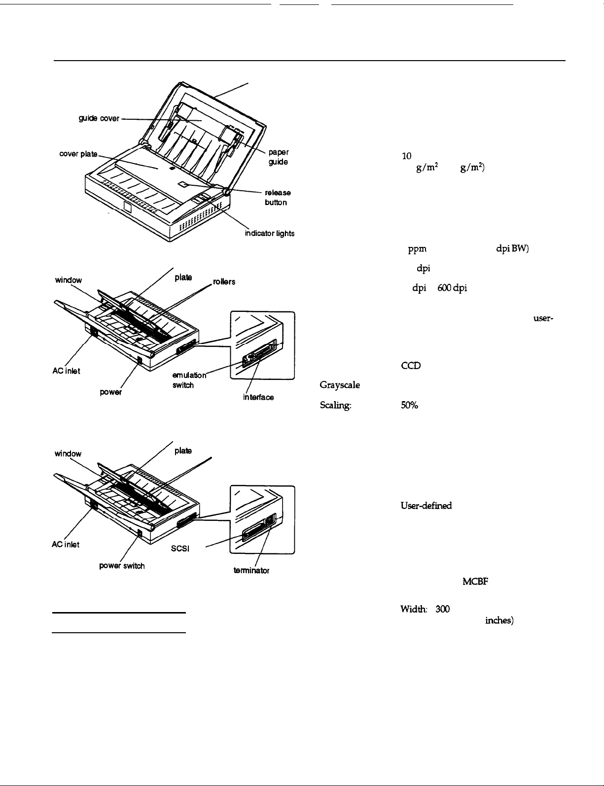
EPSON ES-300GS
scanning
rubber
friction
scanner cover
Maximum 216 mm by 356 mm (8.5 inches by
document size: 14 inches) US legal size
Minimum
document size:
55 mm by 90 mm (2.2 inches by
3.5 inches) business card (with the
attachable card guide)
Document
capacity:
sheets standard paper
(60
to 90
5 sheets for thermal paper
(thickness 0.05 mm)
7 sheets for checks (thickness 0.16 mm)
3 sheets for business cards (thickness
0.1 mm to 0.23
mm)
with the attachable
card guide
Scanning speed:
Optical resolution:
Output resolution:
Output mode:
4
(A4 or letter, 300
300
50
to
Error diffusion: 3 modes
Dither: 4 resident modes and one user-
defined mode
A/D converter:
8 bits
Image sensor:
switch
rubber
scanning
friction
interface
connector
Scanner Specifications
Scanner type:
Photoelectric
device:
Sheet-fed image scanner, monochrome
CCD line sensor
parallel
connector
rollers
switch
levels:
Text enhancement:
Brightness:
Contrast:
Gamma correction:
sharpness:
Interface:
Light source:
Reliability:
Dimensions
and weight:
Paper feed:
256 levels
Background elimination technology
7 levels
256 levels
5 resident tables (linear, analog monitor,
3 printers)
5 levels
Bidirectional parallel or SCSI
White fluorescent lamp
Main unit:
Lamp life:
Depth:
Height:
2000 hours
210 mm (8.3
66 mm (2.6 inches)
Weight: approx. 2.9 kg (6.3 lb)
Input:
output:
face down
face down
Scanners
4/96
EPSON ES-300GS-1
Page 2
EPSON ES-300GS
Electrical Specifications
100 V-120 V model
Rated voltage:
Input voltage
range:
Rated frequency:
Input frequency
Power
consumption:
49.5 Hz to
Approx.
Hz
Safety and EMI
Safety regulation:
1950,
FCC
108.8 Class
22.2 No. 950
Class
Paper
Size:
Paper quality:
Maximum:
Minimum:
55 mm by 90 mm (2.2 inches by
3.5 inches) with the attachable
card guide
216 mm by 356 mm
(8.5 inches by 14 inches)
(3 inches by 5 inches)
Environmental Conditions
Temperature:
Humidity:
Operating
conditions:
Operation: to 35”
Storage: -25”
Operation: 10% to 80%, without
condensation
Storage: 10% to 85%, without
condensation
Ordinary office or home conditions
Extremely dusty environments should
be avoided
Operation under direct sunlight or near
a strong light source should be avoided
to 60”
(40’ F to
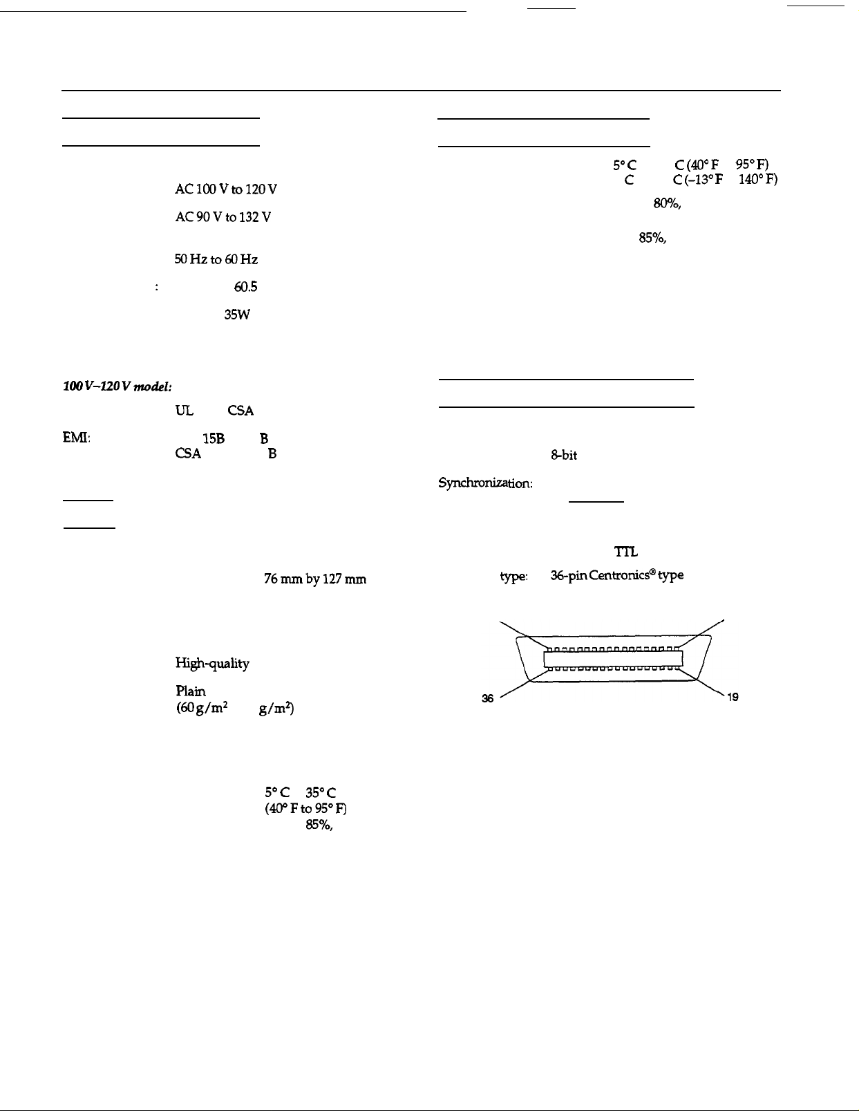
Parallel Interface Specifications
Interface type:
Data format:
Handshaking:
Logic level:
Connector
Connector pin arrangement:
18
Bidirectional parallel interface
By external strobe pulse
By ACKNLG and BUSY signals
Input/output data and interface control
signals are TTL level compatible
CentronicP
connector
to
1
Paper type:
Thermal paper (thickness 0.05 mm)
Check (thickness 0.16 mm)
Business card (thickness 0.1 mm to
0.23 mm)
Paper condition:
Temperature:
Humidity:
EPSON ES-300GS-2
to 90
to
40% to
no condensation
4/96
Scanners
Page 3

EPSON ES-300GS
Signal
Pin
pin
2
3
4
5
6
7
8
9 27
10
11
19
20
21
22
23
24
25
26
28
29
STROBE
DATA2
DATA3
DATA4
DATA5
DATA6
DATA7
ACKNLG
IN/OUT
IN/OUT
IN/OUT
STROBE pulse
in or sand out data.
more than 0.5
These
when data is logical
and low when
logical 0.
Low
has been received and
When
high, the scanner
cannot
The signal
during data entry
2) during scanning
3) when the scanner is
to
read
width must be
at the
terminal.
of bits 1 to
Each
is
pulse.
that data
signal is
data.
Timing charts
The figures below show the timing for the bidirectional
parallel interface as viewed from the scanner.
OUT (from scanner to computer):
IN (from computer to scanner):
4) when the scanner
has an
12-15
16
18
31
NC
NC
Not used
ground
Scanner chassis
Not used
Twisted pair
signal ground level
IN
When this
scanner is
state when power is
on. This level is
usually High. The
than
level
low. the
to the
sure to use a twisted-pair cable for each signal, and to
complete the connection on the return side. These cables
should be shielded and the ground connected to the
chassis of the host computer and the scanner.
SCSI
Interface type:
Specifications
ANSI X3.131-1986 standard
The following functions are included:
BUS FREE phase
phase
SELECTION/RESELECTION phase
COMMAND phase
(Logical Unit number is fixed to 0 and
command link function is not supported)
DATA phase
Data in phase
Data out phase
STATUS phase
MESSAGE phase
MESSAGE IN phase
MESSAGE OUT phase
condition
RESET condition
Logic level:
Electrical standard: As per ANSI X3.131-1986 standard
ID setting
Selectable from 0 to 7 with push buttons
(8
should not be selected; 9 selects the
or
emulation mode)
All interface conditions are based on TTL level.
Scanners
4/96
EPSON ES-30OGS-3
Page 4

EPSON ES-300GS
Connector type:
Signal pin assignments
In this table, the direction of the signals is given relative to
the scanner.
Problems and Solutions
involve the operation of your software and computer.
Problems fall in the following major categories:
Incorrect setup of the interface
Inappropriate selection of the
Incorrect setup of your computer or software
Incorrect operation of your software
Incorrect loading of documents.
Also see the documentation that came with your software
and computer for possible solutions.
Indicator lights
If an error occurs, the scanner stops operating and the
Ready
and
Error type
Fatal
Error lights
error
show the
on
Flashing
Command error
functions
of error.
on
Flashing
flashing
Initialization
The scanner can be initialized (returned to a fixed set of
conditions) in the following ways.
Hardware initialization:
the power is turned on.
When the scanner receives an
interface (pin 31 goes low).
interface.
Software initialization:
When the software command ESC @ (initialize the
scanner) is received.
signal at the parallel
The scanner has received incorrect commands from your
scanning software. When this error occurs, retry the scanning
operation. The scanner returns to normal operation when it
receives correct commands. Normally you do not need to
reset the scanner, which is done by turning the scanner off
and then on.
scanner, wait at least 20 seconds
turning it back on. Rapidly turning it on and
damage the scanner.
Interface error
The scanner may not be properly connected to the computer.
Check the interface
and back on to reset it.
The interrupt settings or the port addresses for the interface
board may not be set correctly or may conflict with
installed expansion boards.
off
When the SCSI Bus Device Message is received.
EPSON ES-300GS-4
4/96
Scanners
Page 5

EPSON ES-300GS
Fatal error
This error indicates one of the following problems:
Paper is jammed in the document feeder.
There is no document
document was not loaded correctly.
The software may not be set up properly.
Check to see if the fluorescent lamp is on. If not, the lamp
may need to be replaced. Contact your dealer or a.qualified
service person for assistance.
jammed in the document feeder. If the scanner still does not
operate properly, or if this error occurs repeatedly, consult
your dealer.
Make sure the document is loaded correctly in the document
feeder, and then resume scanning.
Check to see that your software is installed correctly. Also
make sure you have selected the correct device driver for the
scanner. See your software manual for details.
Note:
clear afntal
it offand then on.
error,
the document feeder or the
will
need to
reset
scanner by
Scanner Bundled Kit
The bundled kit for the scanner includes the following:
ES-300GS-PC
ES-3OOGS Personal
Document Station
Bidirectional parallel
interface card
Attachable card guide
Parallel interface cable
Management Suite”
for Microsoft@ Windows””
ES-300GS-MAC
ES-300GS Personal
Document Station
SCSI interface cable
Attachable card guide
Document
Management
Suite
Archival
Information Reference List
Engineering Change Notices
None
Product Support Bulletins
None
Technical Support Bulletins
None
Related Documentation
TM-ES3COGS
PL-ES3OOGS
4003693
CPD2766 4/95
CPD3392 3/96
ES-3OOGS Service Manual
ES-3OOGS Parts Price List
ES-3OOGS User’s Guide
Getting Started
Getting
Started
Scanners
4/96
EPSON ES-300GS-5
 Loading...