

Page 1
EPSON
®
Professional Series
17” Monitor
I
User’s
Guide
Page 2

FCC COMPLIANCE STATEMENT FOR AMERICAN USERS
This equipment has been tested and found to comply with the limits for a class B
digital device, pursuant to Part 15 of the FCC Rules. These limits are designed to
provide reasonable protection against harmful interference in a residential
installation. This equipment generates, uses and can radiate radio frequency
energy and, if not installed and used in accordance with the instructions, may
cause harmful interference to radio or television reception. However, there is no
guarantee that interference will not occur in a particular installation. If this
equipment does cause interference to radio and television reception, which can
be determined by turning the equipment off and on, the user is encouraged to try
to correct the interference by one or more of the following measures:
l
Reorient or relocate the receiving antenna
l
Increase the separation between the equipment and receiver
l
Connect the equipment into an outlet on a circuit different from that to which
the receiver is connected
l Consult the dealer or an experienced radio/TV technician for help.
WARNING
The connection of a non-shielded equipment interface cable to this equipment
will invalidate the FCC Certification of this device and may cause interference
levels which exceed the limits established by the FCC for this equipment. It is the
responsibility of the user to obtain and use a shielded equipment interface cable
with this device. If this equipment has more than one interface connector, do not
leave cables connected to unused interfaces.
Changes or modifications not expressly approved by the manufacturer could
void the user’s authority to operate the equipment.
FOR CANADIAN USERS
This digital apparatus does not exceed the Class B limits for radio noise
emissions from digital apparatus as set out in the radio interference regulations
of the Canadian Department of Communications.
Le present appareil
les limites
rPglement
applicables
sur le brouillage
Communications du Canada.
numkrique n’6met
aux appareils
radio&zctrique &ii&
pas de bruits
numkiques
radioelectriques d6passant
de Classe B
prescrites
par le Ministere des
dans le
Page 3

IMPORTANT NOTICE
DISCLAIMER OF WARRANTY
Epson America makes no representations or warranties, either express or implied, by or
with respect to anything in this manual, and shall not be liable for any implied
warranties of merchantability and fitness for a particular purpose or for any indirect,
special, or consequential damages. Some states do not allow the exclusion of incidental
or consequential damages, so this exclusion may not apply to you.
COPYRIGHT NOTICE
All rights reserved. No part of this publication may be reproduced, stored in a retrieval
system, or transmitted, in any form or by any means, electronic, mechanical,
photocopying, recording, or otherwise, without the prior written permission of Epson
America, Inc. No patent liability is assumed with respect to the use of information
contained herein. While every precaution has been taken in the preparation of this
publication, Epson America assumes no responsibility for errors or omissions. Nor is
any liability assumed for damages resulting from the use of the information contained
herein. Further, this publication and features described herein are subject to change
without notice.
TRADEMARKS
Epson is a registered trademark of Seiko Epson Corporation.
General notice: Other product names used herein are for identification purposes only
and may be trademarks of their respective companies.
Copyright 0 1991 by Epson America, Inc.
Torrance, California
ii
Y72890200100
Page 4

Important Safety Instructions
1.
Read all of these instructions and save them for later reference.
2.
Follow all warnings and instructions marked on the monitor and
in this manual.
3.
The monitor contains shock hazard potential. Do not attempt to
open or remove any covers, and do not attempt to service the
monitor yourself. Refer all servicing to authorized service
personnel.
4.
Never push objects of any kind into the monitor through cabinet
slots.
Do not expose the monitor to liquids, such as rain or spills.
5.
6.
Do not place the monitor near a heating appliance or in direct
sunlight.
7.
Do not place the monitor on an unstable cart, stand, or table, and
be careful not to drop it.
a.
Slots and openings in the top and bottom of the cabinet are
provided for ventilation; do not block or cover these openings.
9.
Be careful not to damage the power cord or plug.
10.
Voltages outside of the monitor’s specified line voltage range may
harm the monitor. The monitor should be operated from the type
of power source indicated on the rear panel marking label.
11.
Plug the power cord only into a grounding-type wall outlet.
12.
Make sure the combined amperage rating for all products
plugged into the wall outlet used for the monitor does not exceed
the amperage rating of the wall outlet.
13.
Do not replace the interface cable with a non-shielded cable.
14.
Unplug the monitor from the wall outlet and the computer before
cleaning. Use a damp cloth for cleaning.
15.
Excessive brightness for long periods may permanently imprint
an image on the screen.
. .
111
Page 5

16. To avoid picture distortion or color disturbance, do not put
devices that generate magnetism (such as speakers or magnetic
screwdrivers) near the monitor.
17.
When the monitor will not be used for a long period of time,
unplug the power cord.
18.
Unplug the monitor from the wall outlet and refer servicing to
authorized service personnel under the following conditions:
A.
If the power cord or plug is damaged.
B.
If the monitor has come into contact with any liquids, such as
rain or spills.
C. If the monitor does not operate normally when the operating
instructions are followed. Adjust only those controls that are
covered by the operating instructions; improper adjustment
of other controls may result in damage and will often require
extensive work by a qualified technician to restore the
product to normal operation.
D.
If the monitor has been dropped or the cabinet or glass
faceplate has been damaged.
E.
If the monitor exhibits a distinct change in performance.
iv
Page 6
Importantes
1.
Lire attentivement les instructions qui suivent. Les conserver en
lieu
stir.
2.
Observer les avertissements marques
rigoureusement les instructions
3.
Le moniteur pose des
tenter de
reparer
autorise
4.
Ne jamais rien introduire dans les ouvertures du
5.
Preserver le moniteur de tout contact
boissons
6.
Ne pas placer le moniteur a
ni en plein soleil.
7.
Ne pas
instable.
le moniteur
mesures
risques
soulever
par le fabricant.
renversees,
laisser
ou d’enlever les couvercles; ne pas essayer de
soi-meme;
etc.
tomber l’appareil.
de
se’curite’
sur
le moniteur et suivre
contenues
de
d&charge
s’adresser au personnel de service
proximite
l?viter
dans le manuel.
electrique. Ne pas
coffre.
avec
l’eau, la pluie, les
d’un appareil de chauffage,
de le placer
sur
un meuble
8.I1 est important de ne pas bloquer les ouvertures
dessus et au dessous de l’appareil: ce sont des prises d’air qui en
assurent la ventilation.
9.
Faire attention a ne pas abimer le cordon electrique ni la prise de
courant.
10.
Un voltage
design6
seulement la source
de l’appareil.
11.
Brancher
de courant a contact de terre.
12. Lamp&age total de toutes les pieces
ne
doit
13. Ne pas remplacer un cordon d’interface par un cordon non
protege.
14. Debrancher le moniteur du
nettoyer. Utiliser seulement un chiffon humide.
inferieur
pour le moniteur pourrait l’endommager. Utiliser
le cordon du moniteur uniquement sur un
pas
depasser
ou
superieur a
d’electricite indiquee sur l/etiquette a l’arriere
la
capacite
celui qui est specifiquement
branchees sur
en amperes du
socle
et de l’ordinateur avant de le
situees sur
socle
le
socle.
le
de prise
m@me socle
V
Page 7

15. Si la
luminosite
de longues periodes, l’image pourrait y rester imprimee de
permanente.
de
l’ecran
reste a sa plus haute
intensite
pendant
facon
16. Pour
17. Debrancher le moniteur lorsqu’on ne devra pas l’utiliser pendant
18. Debrancher le moniteur et s’adresser au personnel de service
eviter
les deformations de l’image ou les perturbations de
couleur,
parleurs ou toumevis magnetiques a
de longues
autorise
A.
B.
C.
D.
E.
ne pas placer de sources de
periodes.
dans les conditions suivantes:
Si le cordon est effiloche ou la prise est endommagee.
Si le moniteur est
pluie ou des boissons
Si le moniteur ne
pas&es
controles decrits
gravement endommager l’appareil en
qui pourrait necessiter l’intervention d’un
pour le remettre en
Si le moniteur est
endommages.
Si la performance du moniteur est nettement
l’ordinaire.
en suivant les instructions.
entre
en contact
renverskes.
repond
pas normalement aux
dans les instructions; il est possible de
&at
de
tombe,
ou si l’ecran ou le
magnetisme
proximite
marche.
telles que
du moniteur.
avec
des liquides comme la
commandes
Ajuster
uniquement les
touchant
les autres, ce
technicien qualifie
coffre
differente
ont
haut-
ete
de
vi
Page 8

Contents
I
Introduction
Where to Get Help
Setting Up the Monitor
Attaching
Connecting the Monitor to Your Computer
Turning On the Monitor
The Control Panel
Adjusting the Brightness and Contrast
The Operate
Using Display Modes
Modifying a Factory-set Display
Recalling a Factory-set Display Mode
Creating a
Troubleshooting
Specifications
..........................................................................................
......................................................................
........................................................................
the Tilt and
.................................................................................
Position..
User-defined
...................................................................................
........................................................................................
Swivel Base
......................................................................
................................................................
..........................................................................
Mode..
Display Mod-e..
..........................................
...........................
...................................
.................................
.....................................
.................................
1
1
2
2
5
9
10
11
11
11
12
14
15
15
17
vii
Page 9

lntroduction
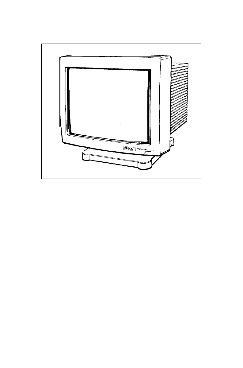
Your Epson® Professional Series monitor is a high-performance, multifrequency color graphics monitor offering the following features:
17-inch, flat-square, analog color CRT display
High-resolution display providing resolutions up to 1024
Seven factory-set display modes, including VGA, 132 column,
Super VGA, interlaced 1024 x 768 (8514/A), and non-interlaced
1024 x 768
Programmable microcontroller memory that allows you to modify
any factory-set display mode as well as create and store up to
seven user-defied display modes
Separate horizontal and vertical sync, composite sync, or sync on
green
Anti-glare screen
Tilt and swivel base.
Additionally, the monitor can run at a vertical refresh rate of up to
90 Hz to provide a flicker-free image.
I
Where to Get Help
If you purchased your Epson product in the United States, Epson
America provides local customer support and service through a
nationwide network of authorized Epson dealers and Service Centers.
Epson also provides the following support services through the Epson
Consumer Resource Center at (800) 922-8911:
x
768
Cl
Assistance in locating your nearest Authorized Epson Reseller or
Service Center
Cl
Technical assistance with the installation, configuration, and
operation of Epson products
Cl
Epson technical information library fax service
Ci
Product literature with technical specifications on our current and
new products
Professional Series Monitor
1
Page 10

Ll
Sales of ribbons, supplies, parts, documentation, and accessories
for your Epson product
tl Customer Relations.
Setting Up the Monitor
You should find the following items in your monitor carton:
Cl
Epson Professional Series 17” monitor
U
Interface cable
Cl
AC power cord
CJ
Tilt and swivel base
Cl
This manual
0
Warranty card
3 Registration card.
If anything is missing or looks damaged, contact your Epson dealer
immediately. Keep the warranty card for your records.
The following sections explain how to attach the tilt and swivel base
and connect the monitor to your computer.
CAUTION
Because the monitor weighs approximately 50 lbs, you may want to ask
another person to help you moue it.
1
Attaching the Tilt and Swivel Base
Before you attach the tilt and swivel base, cover your work area with a
blanket or foam pad to avoid scratching the monitor during assembly.
Then follow these steps:
1.
Turn the monitor over onto the padding with the screen facing
down and the bottom of the monitor on your left, as shown in the
following figure. Locate the four pairs of slots.
Professional Series Monitor
2
Page 11

2.
Make sure the upper sliding portion of the tilt and swivel base is
flat and parallel to the bottom portion of the base, as shown
below. Notice the four pairs of hooks and the locking tab on the
top of the base.
locking tab
hooks
I
bottom portion of base
upper portion of base
Professional Series Monitor
3
Page 12

3.
Position the base next to the bottom of the monitor and fit the
hooks into the slots on the monitor.
Professional Series Monitor
4
Page 13

4.
As shown below, press the top comers of the base toward the
monitor. The base slides downward as you press the corners.
Then press the locking tab on the base toward the monitor’s
connectors until it snaps into place. (This may require some force.)
locked
position
Leave the monitor lying on its screen until after you follow the
instructions in the next section.
m
Connecting the Monitor to Your Computer
The Epson Professional Series monitor accepts separate horizontal and
vertical sync, composite sync, and sync on green. Epson computers
use separate horizontal and vertical sync signals.
The interface cable that comes with the monitor has five color-coded
cables which you connect to the five BNC connectors on the monitor.
Using this interface cable, you can connect the monitor to an industrystandard, 15-pin, D-type, VGA connector on your computer. (All
current Epson computers have this type of connector.)
Professional Series Monitor
5
Page 14

If your computer or video adapter card does not have a VGA
connector, you cannot use the interface cable that comes with the
monitor. Determine the sync requirements of your video display
controller and see the signal connector table on page 18 to determine
which interface cable(s) you need. (See your dealer if you need help.)
Then connect the appropriate interface cable(s) to the connector(s) on
the monitor and computer. Perform only the appropriate steps below.
CAUTION
Before you connect the monitor to your computer, make sure the monitor,
compute-r, and all other peripherals are turned off.
Follow these steps to connect the monitor to your computer:
1.
With the screen still facing down, notice the five monitor
connectors labeled R, G/S, B, H/C, and V.
6
Professional Series Monitor
Page 15

2.
First connect the red cable to the monitor connector labeled R. To
do this, align the cutouts in the rotating metal barrel of the cable
connector with the tabs on the monitor connector.
tabs
3.
Fitting the cable connector’s barrel over the monitor connector,
insert the cable connector into the monitor connector. Then turn
the cable connector’s barrel clockwise as far as possible.
Professional Series Monitor
7
Page 16

4.
Use the same method to connect the green cable to the
G/S
connector, the blue cable to the B connector, the white cable to the
H/C connector, and the black cable to the V connector.
5.
Plug the monitor’s power cord into the power socket on the
monitor.
CAUTION
Epson computers can support the weight of the monitor. If you plan to
place your monitor on top of another type of computer, first verify that
the computer can support the monitor’s weight (50 lbs).
6.
Turn the monitor upright and place it where you will be using it.
7.
Plug the interface cable into the video interface on your computer
and tighten the screws on the connector. (For more information on
connecting a monitor
to your computer, see the user’s manual for
your computer or video adapter card.)
Note
The monitor contains a universal power supply, so you can connect it to
a 90-132 or 180-264 volt power supply with a 48-63 Hz line frequency.
8
Professional Series Monitor
Page 17

8.
Plug the monitor’s power cord into a grounded electrical outlet.
9.
You may need to change your computer’s DIP switch or setup
program setting(s) to match the monitor. If you are using a video
adapter card, you may need to set one or more DIP switches or
jumpers on the card. See your computer or video adapter card
users manual.
Turning On the Monitor
Follow these steps to turn on your monitor and computer:
1.
Turn on your computer.
2.
To turn on the monitor, press the left side of the power switch
(marked
Allow 30 seconds for an image to appear.
-1.
The power indicator lights up after a few seconds.
power switch
panel
Professional Series Monitor
9
Page 18

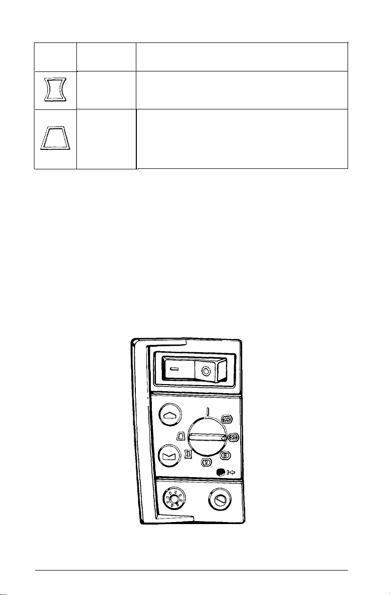
The Control Panel
This section describes the use of the control panel, shown below.
power switch
increment button
decrement button
brightness control
Control
Power switch
Selector switch
Increment and
decrement buttons
Recall button
Brightness control
Contrast control
selector switch
recall button
contrast control
Function
Turns the monitor on and off
Selects the display setting you want to adjust
Adjust display settings
Recalls factory-set display settings (if any) for the
current display mode
Adjusts the background brightness
Adjusts the contrast between the background and the
foreground
10
Professional
Series
Monitor
Page 19

1
Adjusting the Brightness and Contrast
To make the image on the screen clear and easy-to-read, use the
brightness and contrast controls. Press the control to make it pop up
and then turn it to adjust the brightness or contrast. When the setting
is correct, you can press the control again to lock it in place. (Locking
the control in place prevents it from being turned accidentally.)
I
The Operate Position
To use the monitor, make sure the selector switch is in the operate
position. In the operate position, the dot on the selector switch is next
to the vertical line, as shown in the illustration of the control panel,
above.
Using Display Modes
A display mode is a type of graphics adapter format. The Epson
Professional Series monitor is a multi-frequency monitor that can use
industry-standard and user-defined display modes.
The monitor’s microcontroller memory contains these seven factoryset display modes:
Cl
VGA 640 x 350
Cl
VGA 640 x 400
Cl
VGA 640 x 480
0
VGA 1056 x 400 (132 column)
Cl
Super VGA 800 x 600
CI
1024 x 768 interlaced (8514/A)
Cl
1024 x 768 non-interlaced.
You can modify the display settings for any factory-set display mode.
If you don’t want to keep your changes, you can recall the original
factory settings. In addition, you can create and store up to seven
user-defined display modes.
Professional Series Monitor
11
Page 20

The monitor automatically selects which display mode to use. Its
microcontroller analyzes the signal input (horizontal and vertical sync
pulses) from the computer, checks the seven factory-set modes and
any user-defined modes (up to seven), and uses the most appropriate
mode in its memory. The signal input depends on your computer and
application software.
This section explains how to modify and recall factory-set display
modes and create user-defined display modes.
Note
The monitor accepts interlaced timing rates. However, interlaced modes are
not recommended because they may cause the image to flicker.
u
Modifying a Factory-set Display Mode
For each factory-set display mode, you can
change
any of six display
settings. The table below describes these settings and shows the
corresponding icon for each one. Refer to this table as you follow the
steps below.
Icon
Wf
i:(
j%=J,
0
i
EJ
[I
Display
setting name
Operate
Width
Horizontal
position
Height
Vertical
position
Function
The selector switch should be in the operate position
when you are using your monitor as usual and not
modifying or creating a display mode.
Adjusts the overall width of the image. Use the
increment button to increase the width and the
decrement button to decrease the width.
Centers the image horizontally. Use the increment
button to move the image right and the decrement
button to move the image left.
Adjusts the overall height of the image. Use the
increment button to increase the height and the
decrement button to decrease the height.
Centers the image vertically. Use the increment button
to move the image up and the decrement button to
move the image down.
12
Professional Series Monitor
Page 21
Icon
Display Function
setting name
Pin cushion/
barrel
Trapezoid
(keystoning)
Straightens the vertical image edges. Use the increment
button to increase the convex flex and the decrement
button to increase the concave flex.
Adjusts the slope of the vertical image edges. Use the
increment button to decrease the width of the top edge
and increase the width
decrement button to increase the width of the top edge
and decrease the width of the bottom edge.
of
the bottom edge. Use the
Follow these steps to modify a factory-set display mode:
1.
Display an image you want to adjust. (This ensures the monitor is
operating in the factory-set mode you want to modify.)
2.
Turn the selector switch to a display setting you
want
to
change.
The table above describes the settings you can choose from.
For example, if you want to center the image horizontally, turn
the selector switch to the horizontal position setting. Make sure
the dot on the selector switch is next to the horizontal position
icon, as shown below.
Professional Series Monitor
13
Page 22

3.
Use the increment and decrement buttons to adjust the image as
described in the table above.
Note
For small changes, press the increment or decrement button once. To
make a setting change continuously, hold down the increment or
decrement button.
4.
Repeat steps 2 and 3 for any other display settings you want to
change.
5.
When you are satisfied with the image you see, save the modified
display setting(s) by turning the selector switch counterclockwise
to the operate position.
m
Recalling a Factory-set Display Mode
Follow these steps to recall a factory-set display mode:
1.
Display an image for which you want to recall the factory settings.
(This ensures the monitor is operating in the factory-set mode you
want to recall.)
2.
Turn the selector switch clockwise to any one of the display
setting positions.
3.
Press the recall button by inserting a narrow instrument, such as a
ball point pen, into the recall hole.
4.
Turn the selector switch counterclockwise to the operate position.
The microcontroller replaces
your
modifications with the original
factory settings for the current display mode.
Note
If the monitor is in a user-defined display mode, the preceding steps have no
effect.
14
Professional
Series
Monitor
Page 23

1
Creating a User-defined Display Mode
If you see dramatically misaligned images when you use a particular
application program, you probably need to create a user-defined
display mode. Follow these steps to create and store a user-defined
display mode:
1.
Display an image you want to align.
2.
Follow steps 2 through 4 under “Modifying a Factory-set Display
Mode” on page 12.
3.
To save your display settings and create a new display mode, turn
the selector switch counterclockwise to the operate position.
The microcontroller’s
display modes at once. When it contains seven user-defined display
modes and you create and store another display mode, the monitor
automatically overwrites
memory.
memory can save
the
oldest user-defined display mode in
up to seven user-defined
Troubleshooting
This section gives solutions to common problems. If none of these
methods solves the problem, see page 1 for information on where to
get help.
The power indicator does not light.
1.
The power switch
2.
The power cord may be unplugged or
sure the power cord is properly connected to both the monitor
and the electrical outlet.
3.
The electrical outlet may be dead. Test the electrical outlet by
plugging in a lamp or other electrical device.
may not
be turned on. Press the power switch.
not
fully connected. Make
Professional Series Monitor
15
Page 24

The power indicator is on, but there is no image on the screen.
1.
Make sure the computer is turned on.
2.
Make sure the interface cable is properly connected to the monitor
and the video interface on the computer. (See “Connecting the
Monitor to Your Computer” on page 5.)
3.
Adjust the contrast and brightness controls. (See page 11.)
4.
Make sure your computer’s DIP switch and setup program
settings match the monitor. If you are using a video card, make
sure any DIP switches
5.
Set up your application program(s) to match the monitor.
or
jumpers on the card are set properly.
The image on the screen is scrambled.
Make sure the input signals are within the monitor’s horizontal and
vertical frequency ranges. (See page 17.)
The image on the screen is dramatically misaligned when you use a
particular application program.
Create a user-defined display mode as described on page 15.
The colors on the screen are abnormal.
Make sure the interface cable is properly connected to the monitor.
(See “Connecting the Monitor to Your Computer” on page 5.)
The image is too big or too small far the screen.
Adjust the width and height settings as described in “Using Display
Modes” on page 11.
The image is not centered on the screen.
Adjust the horizontal and vertical position settings as described in
“Using Display Modes” on page 11.
The image is distorted.
Adjust the pin cushion/barrel and trapezoid settings as described in
“Using Display Modes” on page 11.
16
Professional Series Monitor
Page 25

Specifications
CRT
Size
Dot pitch
Phosphor persistence
Transmission
Deflection angle
Anti-glare treatment
17 inches (diagonal), flat square
0.26
mm
Medium short
Approximately 50%
90”
Silica coating
Display
Image size
Aspect ratio
Interfacing Requirements
Input signal
Video input
Input impedance 75 ohms
Horizontal frequency
Vertical frequency
(non-interlaced
refresh rate)
11.8
inches x 8.7 inchesf.12
(300mm x 225mmf3mm)
4:3
Analog video and TTL sync
0 to 0.714 v
30 to 57 KHz
50 to 90 Hz
inches
Professional
Series Monitor
I7
Page 26

Signal connectors
Five BNC connectors: R, G/S, B, H/C, and V
(red, green/sync, blue, horizontal/combined,
and vertical)
BNC
connectors
R
G/S
B
H/C
V
Separate horizontal
and vertical sync
Green
Blue
Horizontal
Vertical
Interface cable
computer connector
15-pin,
D-sub, male connector
Pin Signal
1
Red
Green 10
2
3
Blue
4
Not connected
5
Self test
6
Red return
7
Green return
8
Blue return
Composite sync
Red
Green
Blue
Vertical/horizontal
N/A
Pin
9
11
12
13
14
15
Sync on green
Red
Green (sync)
Blue
N/A
N/A
Signal
Not connected
Digital ground
Digital ground
Not connected
Horizontal sync
Vertical sync
Not connected
Factory-set Display Modes
VGA
Super VGA
1024 x 768
I8
Professional Series Monitor
640 dots x 350 lines
640 dots x 400 lines
640 dots x 480 lines
1056 dots x 400 lines
800 dots x 600 lines
1024 dots x 768 lines interlaced (8514/A)
1024 dots x 768 lines non-interlaced
(132
column)
Page 27

Sync Signal Polarity
Mode
VGA 640 dots x 350 lines
I
VGA 640 dots x 400 lines
VGA 640 dots x 480 lines
VGA 1056 dots x 400 lines
(132 column)
Super VGA 800 dots x 600 lines
1024 x 768 interlaced (8514/A)
1024 x 768 non-interlaced
I
AC Line Voltage
90
to 132
Automatic line voltage selection
Input Power
135 watts maximum
Environmental Requirements
Condition
Temperature
and
180 to 264
Operating
range
40”
to 95” F
(5” to 35”
I I
I
I I
VAC; 48
C)
H
t
-
t
t
to 63
Non-operating
range
-4” to 140” F
-20”
V
t
t
t
Hz
to 60” C)
I
I
Humidity
(noncondensing)
Altitude
20%
to 80%
10,000 ft
(3000
m)
maximum
5% to 90%
40,000
ft
(12,000 m)
maximum
Professional Series Monitor
19
Page 28

Dimensions
Width
Height
Depth
Weight
16.4 inches (411 mm)
15.5 inches (388 mm)
17.4 inches (435 mm)
50 lbs (22.5 kg)
20 Professional Series
Monitor
Page 29

Epson America, Inc.
20770 Madrona Ave.
I
Torrance, CA 90503
 Loading...