

Page 1
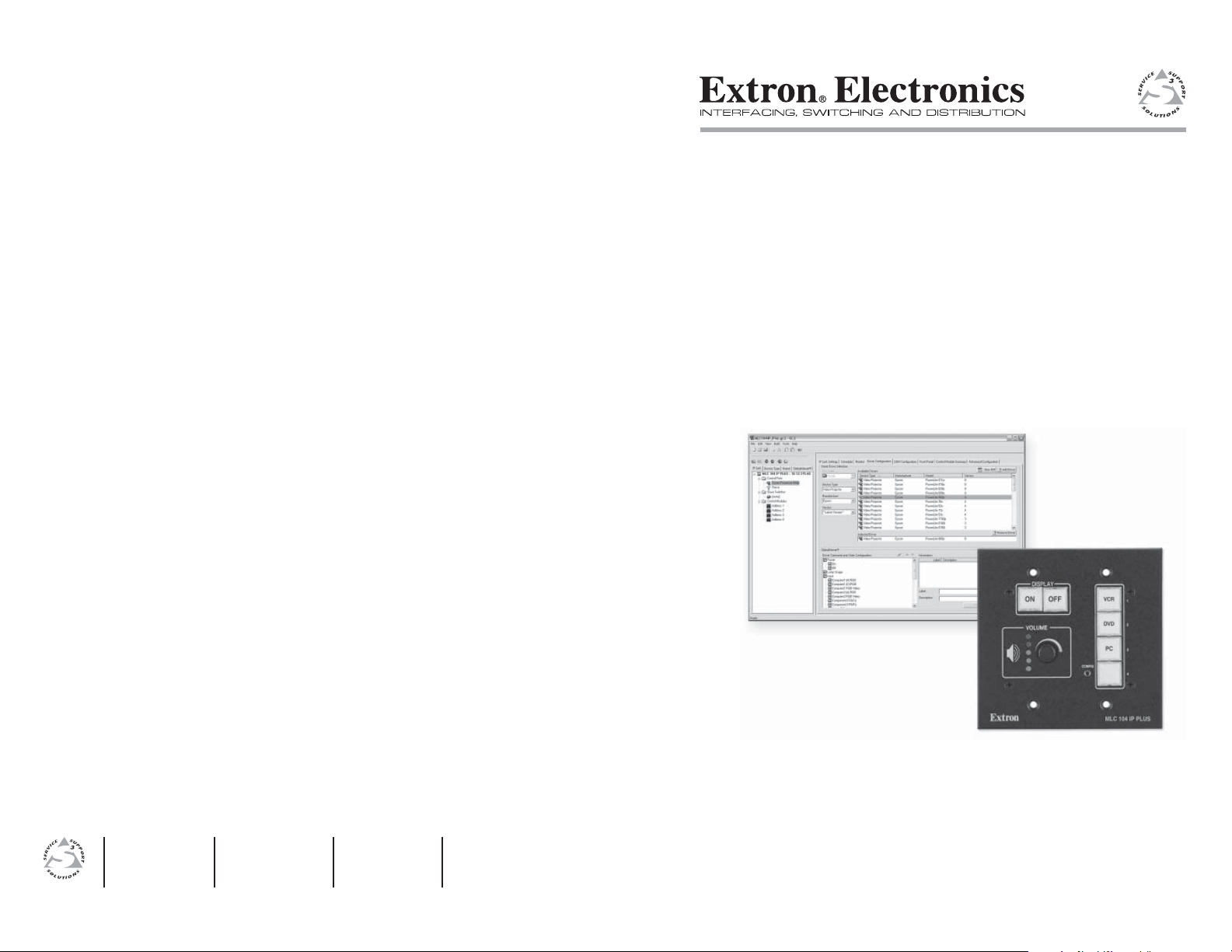
Setup Guide
www.extron.com
Extron Electronics, USA
1230 South Lewis Street
Anaheim, CA 92805
USA
714.491.1500
Fax 714.491.1517
Extron Electronics, Europe
Beeldschermweg 6C
3821 AH Amersfoort
The Netherlands
+31.33.453.4040
Fax +31.33.453.4050
© 2006 Extron Electronics. All rights reserved.
Extron Electronics, Asia
135 Joo Seng Road, #04-01
PM Industrial Building
Singapore 368363
+65.6383.4400
Fax +65.6383.4664
Extron Electronics, Japan
Kyodo Building
16 Ichibancho
Chiyoda-ku, Tokyo 102-0082 Japan
+81.3.3511.7655
Fax +81.3.3511.7656
MLC 104 IP Plus
MediaLinkTM Controller
68-1289-01 Rev. A
08 06
Page 2
Precautions
Safety Instructions • English
This symbol is intended to alert the user of important
operating and maintenance (servicing) instructions in
the literature provided with the equipment.
This symbol is intended to alert the user of the
presence of uninsulated dangerous voltage within
the product’s enclosure that may present a risk of
electric shock.
Caution
Read Instructions • Read and understand all safety and operating
instructions before using the equipment.
Retain Instructions • The safety instructions should be kept for future
reference.
Follow Warnings • Follow all warnings and instructions marked on the
equipment or in the user information.
Avoid Attachments • Do not use tools or attachments that are not
recommended by the equipment manufacturer because they may be
hazardous.
Consignes de Sécurité • Français
Ce symbole sert à avertir l’utilisateur que la
documentation fournie avec le matériel contient des
instructions importantes concernant l’exploitation et
la maintenance (réparation).
Ce symbole sert à avertir l’utilisateur de la présence
dans le boîtier de l’appareil de tensions dangereuses
non isolées posant des risques d’électrocution.
Attention
Lire les instructions• Prendre connaissance de toutes les consignes de
sécurité et d’exploitation avant d’utiliser le matériel.
Conserver les instructions• Ranger les consignes de sécurité afi n de pouvoir
les consulter à l’avenir.
Respecter les avertissements • Observer tous les avertissements et consignes
marqués sur le matériel ou présentés dans la documentation utilisateur.
Eviter les pièces de fi xation • Ne pas utiliser de pièces de fi xation ni d’outils
non recommandés par le fabricant du matériel car cela risquerait de poser
certains dangers.
Sicherheitsanleitungen • Deutsch
Dieses Symbol soll dem Benutzer in der im
Lieferumfang enthaltenen Dokumentation
besonders wichtige Hinweise zur Bedienung und
Wartung (Instandhaltung) geben.
Dieses Symbol soll den Benutzer darauf aufmerksam
machen, daß im Inneren des Gehäuses dieses
Produktes gefährliche Spannungen, die nicht isoliert
sind und die einen elektrischen Schock verursachen
können, herrschen.
Achtung
Lesen der Anleitungen • Bevor Sie das Gerät zum ersten Mal verwenden,
sollten Sie alle Sicherheits-und Bedienungsanleitungen genau durchlesen
und verstehen.
Aufbewahren der Anleitungen • Die Hinweise zur elektrischen Sicherheit
des Produktes sollten Sie aufbewahren, damit Sie im Bedarfsfall darauf
zurückgreifen können.
Befolgen der Warnhinweise • Befolgen Sie alle Warnhinweise und
Anleitungen auf dem Gerät oder in der Benutzerdokumentation.
Keine Zusatzgeräte • Verwenden Sie keine Werkzeuge oder Zusatzgeräte,
die nicht ausdrücklich vom Hersteller empfohlen wurden, da diese eine
Gefahrenquelle darstellen können.
Instrucciones de seguridad • Español
Este símbolo se utiliza para advertir al usuario
sobre instrucciones importantes de operación y
mantenimiento (o cambio de partes) que se desean
destacar en el contenido de la documentación
suministrada con los equipos.
Este símbolo se utiliza para advertir al usuario sobre
la presencia de elementos con voltaje peligroso sin
protección aislante, que puedan encontrarse dentro
de la caja o alojamiento del producto, y que puedan
representar riesgo de electrocución.
Precaucion
Leer las instrucciones • Leer y analizar todas las instrucciones de operación y
seguridad, antes de usar el equipo.
Conservar las instrucciones • Conservar las instrucciones de seguridad para
futura consulta.
Obedecer las advertencias • Todas las advertencias e instrucciones marcadas
en el equipo o en la documentación del usuario, deben ser obedecidas.
Evitar el uso de accesorios • No usar herramientas o accesorios que no
sean especifi camente recomendados por el fabricante, ya que podrian
implicar riesgos.
Warning
Power sources • This equipment should be operated only from the power source
indicated on the product. This equipment is intended to be used with a main power
system with a grounded (neutral) conductor. The third (grounding) pin is a safety
feature, do not attempt to bypass or disable it.
Power disconnection • To remove power from the equipment safely, remove all power
cords from the rear of the equipment, or the desktop power module (if detachable),
or from the power source receptacle (wall plug).
Power cord protection • Power cords should be routed so that they are not likely to be
stepped on or pinched by items placed upon or against them.
Servicing • Refer all servicing to qualifi ed service personnel. There are no user-
serviceable parts inside. To prevent the risk of shock, do not attempt to service
this equipment yourself because opening or removing covers may expose you to
dangerous voltage or other hazards.
Slots and openings • If the equipment has slots or holes in the enclosure, these are
provided to prevent overheating of sensitive components inside. These openings
must never be blocked by other objects.
Lithium battery • There is a danger of explosion if battery is incorrectly
replaced. Replace it only with the same or equivalent type recommended by
the manufacturer. Dispose of used batteries according to the manufacturer’s
instructions.
Avertissement
Alimentations• Ne faire fonctionner ce matériel qu’avec la source d’alimentation
indiquée sur l’appareil. Ce matériel doit être utilisé avec une alimentation principale
comportant un fi l de terre (neutre). Le troisième contact (de mise à la terre) constitue
un dispositif de sécurité : n’essayez pas de la contourner ni de la désactiver.
Déconnexion de l’alimentation• Pour mettre le matériel hors tension sans danger,
déconnectez tous les cordons d’alimentation de l’arrière de l’appareil ou du module
d’alimentation de bureau (s’il est amovible) ou encore de la prise secteur.
Protection du cordon d’alimentation • Acheminer les cordons d’alimentation de
manière à ce que personne ne risque de marcher dessus et à ce qu’ils ne soient pas
écrasés ou pincés par des objets.
Réparation-maintenance • Faire exécuter toutes les interventions de réparation-
maintenance par un technicien qualifi é. Aucun des éléments internes ne peut être
réparé par l’utilisateur. Afi n d’éviter tout danger d’électrocution, l’utilisateur ne doit
pas essayer de procéder lui-même à ces opérations car l’ouverture ou le retrait des
couvercles risquent de l’exposer à de hautes tensions et autres dangers.
Fentes et orifi ces • Si le boîtier de l’appareil comporte des fentes ou des orifi ces, ceux-ci
servent à empêcher les composants internes sensibles de surchauffer. Ces ouvertures
ne doivent jamais être bloquées par des objets.
Lithium Batterie • Il a danger d’explosion s’ll y a remplacment incorrect de la batterie.
Remplacer uniquement avec une batterie du meme type ou d’un ype equivalent
recommande par le constructeur. Mettre au reut les batteries usagees conformement
aux instructions du fabricant.
Vorsicht
Stromquellen • Dieses Gerät sollte nur über die auf dem Produkt angegebene
Stromquelle betrieben werden. Dieses Gerät wurde für eine Verwendung mit einer
Hauptstromleitung mit einem geerdeten (neutralen) Leiter konzipiert. Der dritte
Kontakt ist für einen Erdanschluß, und stellt eine Sicherheitsfunktion dar. Diese
sollte nicht umgangen oder außer Betrieb gesetzt werden.
Stromunterbrechung • Um das Gerät auf sichere Weise vom Netz zu trennen, sollten
Sie alle Netzkabel aus der Rückseite des Gerätes, aus der externen Stomversorgung
(falls dies möglich ist) oder aus der Wandsteckdose ziehen.
Schutz des Netzkabels • Netzkabel sollten stets so verlegt werden, daß sie nicht im
Weg liegen und niemand darauf treten kann oder Objekte darauf- oder unmittelbar
dagegengestellt werden können.
Wartung • Alle Wartungsmaßnahmen sollten nur von qualifi ziertem Servicepersonal
durchgeführt werden. Die internen Komponenten des Gerätes sind wartungsfrei.
Zur Vermeidung eines elektrischen Schocks versuchen Sie in keinem Fall, dieses
Gerät selbst öffnen, da beim Entfernen der Abdeckungen die Gefahr eines
elektrischen Schlags und/oder andere Gefahren bestehen.
Schlitze und Öffnungen • Wenn das Gerät Schlitze oder Löcher im Gehäuse aufweist,
dienen diese zur Vermeidung einer Überhitzung der empfi ndlichen Teile im
Inneren. Diese Öffnungen dürfen niemals von anderen Objekten blockiert werden.
Litium-Batterie • Explosionsgefahr, falls die Batterie nicht richtig ersetzt
wird. Ersetzen Sie verbrauchte Batterien nur durch den gleichen oder einen
vergleichbaren Batterietyp, der auch vom Hersteller empfohlen wird. Entsorgen Sie
verbrauchte Batterien bitte gemäß den Herstelleranweisungen.
Advertencia
Alimentación eléctrica • Este equipo debe conectarse únicamente a la fuente/tipo
de alimentación eléctrica indicada en el mismo. La alimentación eléctrica de este
equipo debe provenir de un sistema de distribución general con conductor neutro
a tierra. La tercera pata (puesta a tierra) es una medida de seguridad, no puentearia
ni eliminaria.
Desconexión de alimentación eléctrica • Para desconectar con seguridad la acometida
de alimentación eléctrica al equipo, desenchufar todos los cables de alimentación
en el panel trasero del equipo, o desenchufar el módulo de alimentación (si fuera
independiente), o desenchufar el cable del receptáculo de la pared.
Protección del cables de alimentación • Los cables de alimentación eléctrica se deben
instalar en lugares donde no sean pisados ni apretados por objetos que se puedan
apoyar sobre ellos.
Reparaciones/mantenimiento • Solicitar siempre los servicios técnicos de personal
califi cado. En el interior no hay partes a las que el usuario deba acceder. Para evitar
riesgo de electrocución, no intentar personalmente la reparación/mantenimiento
de este equipo, ya que al abrir o extraer las tapas puede quedar expuesto a voltajes
peligrosos u otros riesgos.
Ranuras y aberturas • Si el equipo posee ranuras o orifi cios en su caja/alojamiento,
es para evitar el sobrecalientamiento de componentes internos sensibles. Estas
aberturas nunca se deben obstruir con otros objetos.
Batería de litio • Existe riesgo de explosión si esta batería se coloca en la posición
incorrecta. Cambiar esta batería únicamente con el mismo tipo (o su equivalente)
recomendado por el fabricante. Desachar las baterías usadas siguiendo las
instrucciones del fabricante.
FCC Class A Notice
Note: This equipment has been tested and found to comply with the limits for a
Class A digital device, pursuant to part 15 of the FCC Rules. These limits are designed
to provide reasonable protection against harmful interference when the equipment is
operated in a commercial environment. This equipment generates, uses and can radiate
radio frequency energy and, if not installed and used in accordance with the instruction
manual, may cause harmful interference to radio communications. Operation of this
equipment in a residential area is likely to cause harmful interference, in which case the
user will be required to correct the interference at his own expense.
Note: This unit was tested with shielded cables on the peripheral devices. Shielded
cables must be used with the unit to ensure compliance.
Extron’s Warranty
Extron Electronics warrants this product against defects in materials and workmanship
for a period of three years from the date of purchase. In the event of malfunction during
the warranty period attributable directly to faulty workmanship and/or materials,
Extron Electronics will, at its option, repair or replace said products or components,
to whatever extent it shall deem necessary to restore said product to proper operating
condition, provided that it is returned within the warranty period, with proof of
purchase and description of malfunction to:
USA, Canada, South America, Europe, Africa, and the Middle East:
and Central America: Extron Electronics, Europe
Extron Electronics Beeldschermweg 6C
1001 East Ball Road 3821 AH Amersfoort
Anaheim, CA 92805, USA The Netherlands
Asia: Japan:
Extron Electronics, Asia Extron Electronics, Japan
135 Joo Seng Road, #04-01 Kyodo Building
PM Industrial Bldg. 16 Ichibancho
Singapore 368363 Chiyoda-ku, Tokyo 102-0082
Japan
This Limited Warranty does not apply if the fault has been caused by misuse, improper
handling care, electrical or mechanical abuse, abnormal operating conditions or nonExtron authorized modifi cation to the product.
If it has been determined that the product is defective, please call Extron and ask for an
Applications Engineer at (714) 491-1500 (USA), 31.33.453.4040 (Europe), 65.6383.4400
(Asia), or 81.3.3511.7655 (Japan) to receive an RA# (Return Authorization number). This
will begin the repair process as quickly as possible.
Units must be returned insured, with shipping charges prepaid. If not insured, you
assume the risk of loss or damage during shipment. Returned units must include the
serial number and a description of the problem, as well as the name of the person to
contact in case there are any questions.
Extron Electronics makes no further warranties either expressed or implied with respect
to the product and its quality, performance, merchantability, or fi tness for any particular
use. In no event will Extron Electronics be liable for direct, indirect, or consequential
damages resulting from any defect in this product even if Extron Electronics has been
advised of such damage.
Please note that laws vary from state to state and country to country, and that some
provisions of this warranty may not apply to you.
Page 3
安全须知 • 中文
这个符号提示用户该设备用户手册中
有重要的操作和维护说明。
这个符号警告用户该设备机壳内有暴
露的危险电压,有触电危险。
注意
阅读说明书 • 用 户 使 用 该 设 备 前 必 须 阅 读 并 理
解 所 有 安 全 和 使 用 说 明 。
保存说明书 • 用户应保存安全说明书以备将来使
用。
遵守警告 • 用户应遵守产品和用户指南上的所有安
全和操作说明。
避免追加 • 不要使用该产品厂商没有推荐的工具或
追加设备,以避免危险。
警告
电源 • 该 设 备 只 能 使 用 产 品 上 标 明 的 电 源 。 设 备
必 须 使 用 有 地 线 的 供 电 系 统 供 电 。 第 三 条 线
( 地 线 ) 是 安 全 设 施 , 不 能 不 用 或 跳 过 。
拔掉电源 • 为安全地从设备拔掉电源,请拔掉所有设备后
或桌面电源的电源线,或任何接到市电系统的电源线。
电源线保护 • 妥善布线, 避免被踩踏,或重物挤压。
维护 • 所有维修必须由认证的维修人员进行。 设备内部
没有用户可以更换的零件。为避免出现触电危险不要自
己试图打开设备盖子维修该设备。
通风孔 • 有些设备机壳上有通风槽或孔,它们是用来防止
机内敏感元件过热。 不要用任何东西挡住通风孔。
锂电池 • 不正确的更换电池会有爆炸的危险。 必须使用
与厂家推荐的相同或相近型号的电池。 按照生产厂的
建议处理废弃电池。
Page 4

Table of Contents
Chapter One • Introduction ................................................... 1-1
About this Manual .................................................................... 1-2
About the MLC 104 IP Plus Medialink™Controllers ........ 1-2
About Global Configurator .................................................... 1-3
System Requirements ...............................................................1-4
Installing the Software ............................................................ 1-5
Updating Firmware ................................................................... 1-5
Chapter Two • MLC 104 IP Plus Hardware Setup ..... 2-1
Right Side Panel Features and Connections ..................... 2-2
Left Side/Top Panel Features and Connections ...............2-8
Front Panel Features and Basic Operation ...................... 2-10
Buttons .................................................................................2-10
Volume control ..................................................................... 2-11
Configuration (host control) port .......................................2-11
Chapter Three • MLC 104 IP Plus Software Setup ... 3-1
Step 1: Download Device Drivers ....................................... 3-3
Step 2: Create a New Project ............................................... 3-4
Step 3: Add an MLC 104 IP Plus Controller and Define
its Location................................................................................... 3-5
Step 4: Define E-mail Settings ............................................3-7
Defining e-mail server settings ............................................. 3-7
Setting up e-mail notifications .............................................3-8
Adding e-mail contacts .......................................................... 3-9
Step 5: Add a Serial and an IR Device .............................. 3-10
Downloading additional drivers ......................................... 3-10
Adding a serial driver ......................................................... 3-11
Adding an IR driver .............................................................. 3-12
Step 6: Configure the Front Panel Buttons .................... 3-13
Configuring an input button ............................................... 3-14
Configuring the On and Off buttons .................................. 3-14
Step 7: Configure the Control Modules Using the
Auto Fill Feature ....................................................................... 3-15
Step 8: Create a Display Shutdown Schedule ............... 3-18
Step 9: Create a Display Lamp Hour Warning E-mail 3-20
Step 10: Create a Display Disconnection E-mail .........3-22
MLC 104 IP Plus • Table of Contents
i
Page 5
Table of Contents, cont’d
Step 11: Build and Upload a Configuration .................. 3-22
Building a configuration ...................................................... 3-22
Uploading a configuration .................................................. 3-23
Accessing GlobalViewer
® ..................................................... 3-24
MLC 104 IP Plus
Chapter One
1
Introduction
68-1289-01 Rev. A
All trademarks mentioned in this manual are the properties of their respective owners.
ii
MLC 104 IP Plus • Table of Contents
About this Manual
About the MLC 104 IP Plus MediaLink Controllers
About Global Configurator
System Requirements
Installing the Software
Updating Firmware
08 06
Page 6
MLC 104 IP Plus • Introduction
Introduction
MLC 104 IP Plus • Introduction
1-2
1-3
R
D
I
R
E
C
T
1
0
0
-
2
4
0
V
1
.
0
A
M
A
X
.
5
0
-
6
0
H
z
A
U
D
I
O
I
N
P
U
T
S
L
I
N
E
L
E
V
E
L
M
O
N
O
A
U
D
I
O
A
U
D
I
O
A
U
X
/
M
I
X
A
D
J
U
S
T
-
4
2
d
B
T
O
+
2
4
d
B
L
R
L
R
1
2
I
N
P
U
T
S
O
U
T
P
U
T
S
V
I
D
E
O
B
G
R
1
2
I
N
P
U
T
S
5
6
L
I
N
E
O
U
T
R
S
-2
3
2/
M
LC
/I
R
T
x
R
x
I
R
1
2
V
A
B
C
P
R
E
A
M
P
A
M
P
L
I
F
I
E
D
O
U
T
P
U
T
2
0
W
A
T
T
S
M
O
N
O
X
F
M
R
C
O
M
4
/
8
o
h
m
1
0
0
V
7
0
V
M
O
N
I
T
O
R
O
U
T
L
R
L
R
1
0
0
-
2
4
0
V
1
.
0
A
M
A
X
.
5
0
-
6
0
H
z
R
S
-
2
3
2
M
L
C
/
I
R
C
O
N
T
R
O
L
A
U
D
I
O
I
N
P
U
T
S
L
I
N
E
L
E
V
E
L
M
O
N
O
A
U
D
I
O
A
U
D
I
O
T
x
R
x
I
R
1
2
V
A
B
C
P
R
E
A
M
P
A
U
X
/
M
I
X
A
D
J
U
S
T
-
4
2
d
B
T
O
+
2
4
d
B
L
R
L
R
R
1
2
I
N
P
U
T
S
O
U
T
P
U
T
S
V
I
D
E
O
H
V
B
G
R
1
2
I
N
P
U
T
S
M
O
N
I
T
OR
O
U
T
5
6
A
M
P
L
I
F
I
E
D
O
U
T
P
U
T
2
0
W
A
T
T
S
M
O
N
O
D
I
R
E
C
T
X
F
M
R
C
O
M
C
O
M
1
0
0
V
7
0
V
4
8
C
O
N
F
I
G
D
I
S
P
L
A
Y
M
L
C
1
0
4
I
P
P
L
U
S
A
A
P
V
O
L
U
M
E
1
2
3
4
O
N
O
F
F
D
V
D
V
C
R
P
C
M
U
T
E
P
L
A
Y
N
E
X
T
/
F
W
D
P
A
U
S
E
S
T
O
P
TUNER
P
R
E
V
/
R
E
W
E
N
T
E
R
T
I
T
L
E
M
E
N
U
D
V
D
&
V
C
R
C
O
N
T
R
O
L
T
x
D
V
D
V
C
R
Extron
IPA T RLY4
Ethernet Control
Relay Box
Extron
SI 3CT LP
Full-Range Ceiling
Speakers
Help Desk PC
Mono Amplified Output
Digital Out
RGBHV
Video
RS-232
RS-232
Extron
MLS 304MA
MediaLink Switcher
Laptop
w/ Audio
Projector
Audio
RGBHV
RGBHV
DVD/VCR
Combo
RGBHV
& Audio
Screen
Control
Extron
IRCM-DV+
Dual Function DVD
and VCR IR Control Module
IR From
MLC 104
Controller
IR Emitter
IR to DVD/VCR
Combo
Extron
WPB 105
Wall Plate
Audio
Extron
MLC 104 IP Plus AAP
MediaLink Controller
Video
I
P
A
T
R
L
Y
4
1
2
3
4
C
I
N
P
U
T
S
TCP/IP
Network
W
P
B
1
0
5
N
E
T
W
O
R
K
C
O
M
P
U
T
E
R
A
U
D
IO
About this Manual
This setup guide allows you to easily and quickly set up
and configure the Extron MLC 104 IP Plus Controller. The
following step by step instructions first show you how to set up
the hardware, then how to use the Global Configurator (GC)
program to
download drivers
•
add A/V devices to a GC configuration
•
configure the front panel buttons
•
set a shutdown schedule
•
set up e-mail alerts that can flag a projector disconnection
•
or warn that lamp hours are exceeded
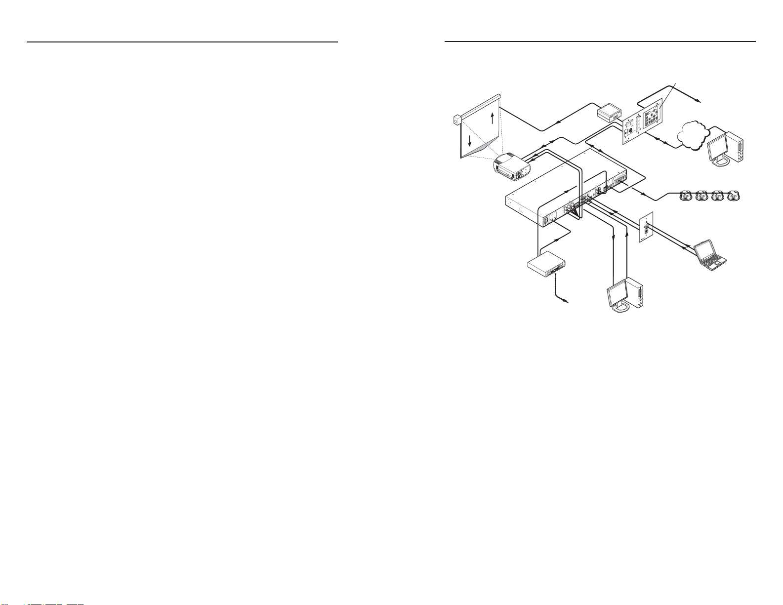
About the MLC 104 IP Plus Medialink™ Controllers
The Extron MLC 104 IP Plus MediaLink Controller can control
a projector and various other items such as VCR and DVD
players.
Throughout this manual, the controllers are referred to as the
MLC 104, MLC, or controller. All models offer RS-232- or
infrared- (IR) based projector (display) control along with IR or
serial control of other devices (typically A/V input sources), and
RS-232 control of an Extron switcher.
The MLC 104 IP Plus Series offers two methods of projector
and source device control: RS-232 or infrared (IR). The MLC
can learn IR signals from remote controls to communicate with
sources such as VCRs and DVD players. Users can create their
own device drivers (through IR or RS-232 control) or go to the
Extron Web site (www.extron.com) to obtain them.
A typical application for an MLC 104 IP Plus
Medialink Controller
About Global Configurator
The Extron Global Configurator (GC) software is an application
that allows non-programmers to configure a wide range
of Extron IP Link®-enabled products, and create entire
GlobalViewer® systems. It provides an integrated environment
for defining A/V control and system monitoring functionality
from an easy-to-use graphical user interface. It allows you to
configure a single room controller as well as build a Web-based
asset management and remote monitoring system for hundreds
of A/V devices in multiple locations.
C
You must use Global Configurator version 2.2 or
later to configure the MLC 104 IP Plus. Using an
earlier version (2.0.0 through 2.1.x) risks damage
to the products. Immediately update any existing
controllers configured with older versions of the
software. See "Installing the Software" later in this
chapter for instructions on how to install GC 2.2.
Page 7

MLC 104 IP Plus • Introduction
Introduction, cont’d
1-4
MLC 104 IP Plus • Introduction
1-5
Global Configurator provides the following features for the
MLC 104 IP Plus:
Offline configuration — Using Global Configurator, you can
configure your MLC 104 IP Plus Medialink controller
without having the device on hand, eliminating the need
to connect your MLC before starting the configuration.
GlobalViewer Web pages — GlobalViewer Web pages (HTML,
XML, and JavaScript) allow you to control and manage
devices such as VCRs, DVDs, and displays connected to
an MLC 104 IP Plus. These pages are generated when you
build and upload your project files in GC.
GlobalViewer pages can be viewed using Microsoft
Internet Explorer® (version 6 and above) from any
computer with access to the network.
System Requirements
The MLC 104 IP Plus and Global Configurator have the
following hardware and software requirements:
Intel® Pentium® III 1 GHz processor
•
Microsoft® Windows operating system
•
• Windows NT service pack 4, or
• Windows 2000 service pack 2, or
• Windows XP service pack 2
Microsoft Internet Explorer® 6.0 or later with ActiveX
•
enabled
Microsoft Windows Script 5.6
•
512 MB of RAM
•
50 MB of available hard disk space
•
A network connection with a minimum data transfer rate
•
of 10 Mbps (100 Mbps is recommended)
Installing the Software
Before getting started with Global Configurator (GC), you must
install the software. The configuration software is available at
no charge via the Extron Web site at www.extron.com.
C
To install the software on your hard drive:
1. Go to www.extron.com and click the Download tab.
2. Click the IP Link® Software link or icon.
3. Click the Global Configurator link or icon.
4. From the Global Configurator page, click the
5. Provide the necessary information, then click the
The program wizard walks you through the remaining process.
By default, the installation creates the necessary directories,
placing icons, files, drivers, and a help file for GC within them.
®
Updating Firmware
Extron periodically updates product firmware in conjunction
with the release of new software revisions. When updating any
Extron software to the latest revision level, please be sure to
read the supplied release notes, or contact an Extron Application
Engineer to determine if your Extron product also requires a
firmware update.
N
You must use Global Configurator version 2.2 or
later to configure the MLC 104 IP Plus. Using an
earlier version (2.0.0 through 2.1.x) risks damage
to the products. Immediately update any existing
controllers configured with older versions of the
software.
Download Now button.
Download GCSWxxxxx.exe button.
For more information regarding how to update the
firmware, refer to appendix B in the
MLC 104 IP Plus User's Manual.
Page 8
Introduction, cont’d
MLC 104 IP Plus
Chapter Two
2
1-6
MLC 104 IP Plus Hardware Setup
Right Side Panel Features and Connections
Left Side/Top Panel Features and Connections
Front Panel Features and Basic Operation
MLC 104 IP Plus • Introduction
Page 9

Hardware Setup
2
3
GRO UN D
1
IR IN
GRO UN D
IR OU T
CM
SC P
GRO UND
GRO UND
Tx
Rx
DISPLAY
RS-232/IR
LAN
PRESS TAB WITH
TWEEKER TO REMOVE
A B
MLS PWR
RS-232 12V
DIGITAL
I/O
A B C D E
COMM LINK
+V OU T
GRO UN D
Tx
Rx
+1 2V IN
MLC 104 IP Plus
Right Side
4
5
3
2
1
6
Projector
Panel
MLC 104 IP Plus
Right Side Panel
DISPLAY
RS-232/IR
GROUND
IR OUT
Tx
Rx
Ground ( )
Receive (Rx)
Transmit (Tx)
Ground ( )
Receive (Rx)
Transmit (Tx)
Bidirectional
MLC 104 IP Plus
Right Side Panel
DISPLAY
RS-232/IR
GROUND
IR OUT
Tx
Rx
G = Ground
IR Emitter 1
White Striped Wire
100'
(30.5 m)
S = Signal (IR)
1ON2 3 4
This chapter describes right, left, and front panel features; basic
front panel operation; and how to connect cables to the
MLC 104 IP Plus controller.
Right Side Panel Features and Connections
Display control RS-232 /IR port — This port has dedicated
a
bidirectional RS-232 and infrared signal output.
From this port, commands sent from a driver or user-defined
command strings (entered via the Global Configurator) can be
sent to the display device.
For bidirectional RS-232 communication, the transmit, ground,
and receive pins must be wired at both the controller and the
projector connectors, as shown below.
For infrared (IR) output, wire an IR Emitter (2 emitters are the
maximum), as shown below, for a modulated signal and ground.
COMM Link — You can connect up to four Extron control
b
modules (IRCMs, ACMs, RCMs, CMs), one Extron IR signal
repeater (IRL 20 or IR Link), and/or two Extron SCP 104 control
pads to this port to allow remote control of the MLC 104 IP Plus
controller or other items. A maximum of seven devices can be
connected to this port.
The SCP 104 replicates the MLC’s front panel controls. The
IR signal repeater can receive IR signals from an optional IR 402
remote control and send them to the controller. Once the MLC
is set up, control modules can be used to control VCRs, DVD
players, tape decks, a projector lift, or screen control. For device
control, refer to the appropriate device’s user’s manual.
The control modules, IR signal repeaters, and SCPs can be daisy
chained, as shown on the following page. Extron Comm-Link
(CTL and CTLP) cable is recommended for these connections.
N
When an SCP 104 is connected to an MLC 104 IP Plus,
the SCP's DIP switch #4 must be in the ON (up) position.
N
Each projector or display may require different wiring. For
details, refer to the manual that came with your projector.
MLC 104 IP Plus • Hardware Setup
The SCP's DIP switch #4 set to ON (up) for an
MLC 104 IP Plus connection
W
The SCP 104 must have firmware version 1.01 or
higher installed.
MLC 104 IP Plus • Hardware Setup
2-32-2
Page 10

MLC 104 IP Plus • Hardware Setup
Hardware Setup, cont’d
2-4
MLC 104 IP Plus • Hardware Setup
2-5
MLC 104 IP Plus
Right Side Panel
COMM LINK
A B C D E
+V OUT
GROUND
CM
IR IN
SCP
E
C
B
A
SCP communication (IR)
Ground ( )
IRCM, ACM, RCM, CM
+12 VDC
C
B
A
Maximum =
2 SCPs
Per System
Maximum =
4 Control
Modules
(4 module
addresses)
Ground ( )
+12 VDC
Ground ( ) & Drain Wire
E
C
B
A
SCP Communication
Control Module Communication
+12 VDC
= White
= Black & Drain Wire
= Violet
= Red
IRCM, ACM, RCM, CM
DVD & VCR CONTROL
PLAY NEXT/FWD PAUSE STOP
TUNER
Tx
PREV/REW
ENTER
TITLE MENU
TV/VCR
DVD VCR
SCP 104
IRCM-DV+
CONFIG
DISPLAY
VOLUME
SCP 104
ON
PC
VCR
DVD
OFF
1
2
3
4
200' (61 m) max.
to Last Device
Extron CTLP Cable Color Code:
1
2
3
GR OUN D
+1 2V OUT
CM
GR OUN D
IR OU T
GR OUN D
SC P
GR OUN D
Tx
Rx
DISPLAY
RS-232/IR
A B C D E
COMM LINK
LAN
PRESS TAB WITH
TWEEKER TO REMOVE
A B
MLS
RS-232
POWER
12V
DIGITAL
I/O
IR IN
Tx
GR OUN D
Rx
+1 2V IN
IPA T RLY4
1 2 3 4 C
INPUTS
MLC 104 IP Plus
Right Side
IPA T RLY4
Front Panel
Relay 1
Relay 2
Relay 3
+12 VDC
24K SW1
2K
+12V +5V
SW2
I/O
GND
An MLC 104 IP Plus controller daisy chained to a
SCP 104 remote panel
3. Connect the MLC 104 IP Plus' digital I/O wires (from
digital I/O ports 1, 2, and 3) to the IPA T RLY4's inputs
(1, 2, and 3), as shown below. The Extron Comm-Link
(CTL and CTLP) cable is recommended for these
connections.
Digital I/O — This port is configurable as a digital input or
c
N
The maximum distance allowed between an MLC
controller and a SCP 104 is 200’ (61 m).
digital output and can be used to connect a variety of devices,
such as sensors, switches, LEDs, and relays.
You can connect the Extron IPA T RLY4 to the MLC to enable a
relay function (to raise a projector screen, for example). To use
the IPA T RLY4 with the MLC 104 IP Plus, do the following:
1. Use Global Configurator to set the MLC's digital I/O ports
N
When the MLC's output signal is applied to one of the
2. Connect the MLC's 12 VDC output to the IPA T RLY4's "C"
to output mode.
Refer to the MLC 104 IP Plus User's Manual for the
steps to set this port to output.
IPA T RLY4's relays, that relay’s NO (normally open)
contacts close and its NC (normally closed) contacts open.
(common voltage) terminal.
N
Refer to the IPA T RLY4 User's Guide for information on
how to wire the IPA T RLY4's relay outputs.
As shown in the illustration below, the digital I/O port is set to
measure two states: on or off; high or low. Its input threshold
voltages are as follows: low is <2.0 V and high is >2.8 V.
An equivalent digital I/O port circuit
Page 11

MLC 104 IP Plus • Hardware Setup
Hardware Setup, cont’d
2-6
MLC 104 IP Plus • Hardware Setup
2-7
MLC/IR
A B C
MediaLink
Switcher's
Rear Panel
MLC/IR Port
NOTE You must connect a
ground wire
between the MLC
and MLS.
RS-232
MLS
A B
Rx
Tx
GROUND
Ground ( )
Transmit (Tx)
B
Receive (Rx)
A
Transmit (Tx)
Receive (Rx)
B
A
MLC 104 IP Plus
Right Side Panel
Connecting an external power supply
to an MLC 104 IP Plus
MLC 104 IP Plus
Right Side Panel
12V
PWR
GROUND
+12V IN
Ground ( )
+12 VDC input
Ground all devices.
An External
Power Supply
(12 VDC, 1 A max.)
Power Supply
Output Cord
Ridges
Smooth
A A
0.2” (5 mm) MAX.
MLC's
Power
Port
12V
PWR
GROUND
+12V IN
SECTION A–A
Both digital input and output modes of the digital I/O ports
have the ability to turn on an internal pull-up resistor to
+ 5 VDC (equivalent to SW2 on the previous illustration).
N
Refer to the MLC 104 IP Plus User's Manual for further
details on configuring this port.
MLS RS-232 connector — This port can control an optional
d
Extron switcher or other RS-232 controllable device.
If you connect an optional switcher (such as an Extron
MLS Series switcher) to the MLC, you must connect a ground
wire between the switcher and the MLC, as shown in the
following diagram.
N
Power the controller via an external power supply, not
from an Extron switcher. The controller requires a
separate 12 VDC power supply.
N
Check the power supply’s polarity before connecting it to
the MLC. See the diagram below.
Power wiring
LAN connector and LEDs — An Ethernet connection can be
f
used on an ongoing basis to control the MLC 104 IP Plus (and
the devices connected to it) in an Ethernet network.
Use a straight-through cable for connection to a switch,
•
hub, or router.
Use a crossover cable for connection directly to a PC.
•
Configure the settings for this port via either SIS commands, an
embedded Web page, or Global Configurator.
LAN port defaults are as follows:
• IP address: 192.168.254.254
• gateway IP address: 0.0.0.0
• subnet mask: 255.255.0.0
• DHCP: off
PWR (power) connector — To provide power to the MLC,
e
connect a cable between this port and a 12 VDC, 1 amp
(maximum) power supply, as shown below. For power wiring
instructions, see the diagram on the following page.
Page 12

MLC 104 IP Plus • Hardware Setup
Hardware Setup, cont’d
2-8
MLC 104 IP Plus • Hardware Setup
2-9
RESET
MLC 104 IP Plus
Left Side
1
IR
1 2 3
4 5 6
7 809
2"–12"
(4–30 cm)
MLC 104 IP Plus
Top Panel
IR
MLC 104 IP Plus
Top Panel
2
Left Side/Top Panel Features and Connections
The IR learning range for the MLC 104 IP Plus
Reset button and LED — Pressing this recessed button causes
a
various IP functions and Ethernet connection settings to be reset
to their factory defaults. For reset modes, refer to chapter 2 in
the MLC 104 IP Plus User's Manual.
IR signal sensor — This sensor allows for IR learning. It
b
receives and "learns" commands from other devices' infrared
remote controls so an IR driver can be created. Refer to the
IR Learner Help File from the IR Learner software for IR learning
procedures. This receiver accepts infrared signals from 30 kHz
to 62 kHz.
N
You can download the IR Learner software from the Extron
Web site (www.extron.com).
N
Because the top panel of the MLC 104 IP Plus is obscured
after wall mounting, perform all IR learning prior to
installation.
Page 13

Hardware Setup, cont’d
CONFIG
DISPLAY
VOLUME
MLC 104 IP PLUS
ON
VCR
DVD
PC
OFF
1
2
3
4
MLC 104 IP Plus
Front Panel
4
2
1
3
6 feet
(1.8 m)
Part #70-335-01
5
1
9
6
Sleeve (Gnd)
Ring
Tip
9-pin D Connection TRS Plug
Pin 2 Computer's RX line Tip
Pin 3 Computer's TX line Ring
Pin 5 Computer's signal ground Sleeve
Front Panel Features and Basic Operation
There are several features that must be set up prior to using the
MLC. Refer to chapter 4 in the MLC 104 IP Plus User's Manual
for details.
Buttons
The MLC 104 IP Plus controller has backlit buttons. The button
caps are removable so the button labels can be changed. For
instructions on how to change the buttons, refer to chapter 1 of
the MCL 104 IP Plus User's Manual.
Display On/Off buttons — After they have been configured
a
Input selection buttons — By default, these buttons are a
b
2-10
MLC 104 IP Plus • Hardware Setup
(for instructions, see "Configuring the On and Off buttons" in
chapter 3), press the On button to turn the display device on,
and press the Off button to power it off. Only one of these two
buttons can be selected (active) at once. You can assign other
functions to these buttons via the Global Configurator software.
mutually exclusive group (only one of these buttons can be
selected at a time).
Press an input selection button to select the desired audio and
video input to the projector or an optional Extron switcher. The
button lights brighter and remains lit while an audio-video
input is selected.
Volume control
Volume knob and LEDs — Rotate this knob to adjust the audio
c
volume. Global Configurator allows you to select whether this
knob will control the projector’s audio levels or the optional
MediaLink switcher’s audio levels.
If the MLC is configured for use with a MediaLink Switcher
or projectors, the MLC’s LEDs light to indicate volume ranges
(with steadily lit LEDs) and minimum/maximum volume limits
(with flashing LEDs).
If the MLC is configured for increment/decrement volume
adjustment, the LEDs scroll up/down briefly.
Configuration (host control) port
Front panel Config port — This 2.5 mm mini stereo jack
d
provides an RS-232 connection for configuration and control.
An optional cable for this port is the 9-pin D Female to 2.5 mm
TRS configuration cable, shown below, (Extron part #70-335-01).
Pinout for TRS RS-232 cable wiring
This port has the following RS-232 protocol:
• 38400 baud
• 1 stop bit
• no parity
• 8 data bits
• no flow control
MLC 104 IP Plus • Hardware Setup
2-11
Page 14

Hardware Setup
MLC 104 IP Plus
Chapter Three
2-12
MLC 104 IP Plus Software Setup
3
Step 1: Download Device Drivers
Step 2: Create a New Project
Step 3: Add an MLC 104 IP Plus Controller and Define its Location
Step 4: Define E-mail Settings
Step 5: Add a Serial and an IR Device
Step 6: Configure the Front Panel Buttons
Step 7: Configure the Control Modules Using the Auto Fill Feature
Step 8: Create a Display Shutdown Schedule
Step 9: Create a Display Lamp Hour Warning E-mail
Step 10: Create a Display Disconnection E-mail
Step 11: Build and Upload a Configuration
MLC 104 IP Plus • Hardware Setup
Page 15

MLC 104 IP Plus • Software Setup
Software Setup
MLC 104 IP Plus • Software Setup
3-2
3-3
1
2
3
4
5
6
7
8
9
10
11
This chapter provides the steps for setting up your
MLC 104 IP Plus controller using the Global Configurator (GC)
software. By means of example, you will learn how to
• Add drivers that allow control of A/V devices.
• Configure the controller's power buttons, and input
selection buttons to control a video projector.
• Configure an IRCM-DV+ control module to control the
functions of a DVD/VCR player.
• Schedule a projector shutdown, create a lamp hour
warning alert, and create a projector disconnection e-mail
alert.
Each of the following steps of configuration are described in
detail in the subsequent sections of this chapter.
Downloading device drivers
Creating a new project
Adding an MLC 104 IP Plus controller and defining its
location
Defining e-mail settings
Adding a serial and an IR device
Configuring the front panel buttons
Configuring the control modules using the Auto Fill
feature
Creating a display shutdown schedule
Creating a display lamp hour warning e-mail
Creating a display disconnection e-mail
Building and uploading a configuration
N
C
This setup guide provides instructions for the primary
setup and configuration of the MLC 104 IP Plus. For
additional information and more detailed instructions,
refer to the MLC 104 IP Plus User's Manual or the
GC Help File accessed through the GC software.
You must use Global Configurator version 2.2 or
later to configure the MLC 104 IP Plus. Using an
earlier version (2.0.0 through 2.1.x) risks damage
to the products. Immediately update any existing
controllers configured with older versions of the
software. See "Installing the Software" in chapter 1
for instructions on how to install GC 2.2.
Step 1: Download Device Drivers
In order to configure an MLC to control a device, you must
download the drivers for each device.
For the purposes of this setup guide and tutorial, you will
download two drivers to use in the following examples: one
serial driver (for a video projector) and one IR driver (for a
DVD/VCR player).
If you prefer to download the drivers required for your own
configuration, replace our example drivers with your own in the
following exercises.
To download the required drivers, do the following:
1. Double-click the GC icon to launch Global Configurator.
The GC 2 Start Options dialog box appears.
2. Click the Add Drivers Subscription button.
3a. From the Available Manufacturers/Device Types box,
choose the required manufacturer(s) from the left window
by clicking its name. For the following exercises, choose
Epson.
3b. From the Available Manufacturers/Device Types box,
choose the required device(s) from the right window by
clicking its icon. For the following exercises, choose video
projector.
4. From the far right column of buttons, click the Subscribe
button. The selected items appear in the Current Driver
Subscriptions window.
5. Repeat steps 3-5 above, choosing Hitachi as the
manufacturer and DVD/VCR as the device.
6. Click the Download button to download the drivers under
the Current Driver Subscriptions window.
N
7. After all of your drivers are successfully subscribed, click
N
If you wish to unsubscribe to a particular driver, check its
check box and then click the Unsubscribe button.
the OK button. The GC 2 Start Options dialog reappears.
When adding new drivers to an open project, you
must close (and save) the configuration for a successful
download. Reopen the configuration to view the
downloaded drivers. See "Step 5: Add Serial and IR
Devices" for detailed instructions.
Page 16

Software Setup, cont’d
Step 2: Create a New Project
1. If the GC 2 Start Options dialog is displayed, select the
"Create a New Project" option and click the OK button.
The Project Settings dialog box appears, as shown below.
N
Project Settings dialog box
You can also access the Project Settings dialog box via
the Edit menu.
Step 3: Add an MLC 104 IP Plus Controller and
Define its Location
The most essential step in creating a configuration in a GC
project is to add an IP Link device. The following steps instruct
how to add an MLC 104 IP Plus into Global Configurator.
N
To add the MLC 104 IP Plus, do the following:
Add Device dialog box (Basic)
1. From the IP Link Device drop-down menu, select
2. Enter or edit the host name or IP address in the
3. In the Display Name box, enter an easy to remember,
4. Click the Advanced button.
If the Add Device dialog box is not displayed, select
Add Device from the Edit menu.
MLC 104 IP Plus.
Name/IP Address text box so that it matches the one
assigned to the product by your network administrator.
descriptive name (e.g., MLC104IPPlus). You may choose
to keep the default name.
3-4
2. If passwords have been set on the MLC, enter the
administrator and user passwords. Ensure that both
passwords are repeated in the Verify fields.
N
3. Click the Sync IP Link device’s time and date to PC’s
4. Click the OK button. The Add Device dialog box appears.
If a password has been set on the MLC 104 IP Plus
controller but none is entered here, you will be unable
to upload a new configuration. By default, there is no
password set on the controller.
time and date check box and fill in the appropriate
Daylight Saving time zone values in the menu drop boxes,
if necessary.
MLC 104 IP Plus • Software Setup
MLC 104 IP Plus • Software Setup
3-5
Page 17

Software Setup, cont’d
Add Device dialog box (Advanced)
5. Select the Auto Configure IP Address check box. The
MAC Address text box becomes active and the first three
octets of the MAC address appear.
6. Locate the MAC address on the rear of the Extron IP
product or obtain it from your network administrator.
7. Enter the remainder of the MAC address in the MAC
Address text box (the first three octets should be filled in).
8. Click the Set button. This assigns the new IP address to
the IP device.
9. Click the New Location button in the upper right corner of
the Add Device dialog box. A Location folder is created,
in edit mode. You can use additional folders to create up
to eight location levels.
10. Assign a location-oriented name to the highlighted folder
(e.g., Room 201).
11. Once finished, click the OK button. The
Global Configurator Front Panel window appears, as
shown on the following page.
The Global Configurator Front Panel window
N
This Global Configurator project can be saved at any time
by selecting Save from the File menu.
Step 4: Define E-mail Settings
Global Configurator supports scheduling, monitoring, and
e-mail alerts for all connected devices (e.g., a video projector).
For example, you can create a schedule to shut down a projector
at a predetermined time, and/or create an e-mail alert that
warns a school administrator if the projector's lamp hours are
nearing expiration.
Defining e-mail server settings
Before you set up e-mail notifications, ensure that your e-mail
server, subnet mask and gateway settings are set. If not, use the
Change Device Setting feature to set them up.
1. From the Tools menu, choose Change Device Settings....
The Device Settings page appears and displays every
device in the current project.
2. Select the MLC 104 IP Plus from the list.
3. From the Settings menu, choose Set Mail Server....
3-6
MLC 104 IP Plus • Software Setup
MLC 104 IP Plus • Software Setup
3-7
Page 18

Software Setup, cont’d
4. Complete each of the fields with your mail server
IP address, mail server domain, and, if necessary, your
user name and password.
5. Click the OK button.
6. Go back to the Settings menu to complete the entries for
your subnet mask and gateway settings.
Setting up e-mail notifications
The Email Manager provides preset messages for some of the
most common actions performed in GC.
To set up an e-mail notification for a specified action, do the
following:
1. From the Global Configurator Edit menu, choose Email
Manager. The Email Manager dialog box appears, as
shown below.
2. Select one of the choices under the Name field.
This action automatically populates the Name, Subject, and
Body fields for the action, but these fields can be altered, if
needed.
To create a custom notification e-mail message, do the following:
1. Fill in name, subject, and body sections in the Email
Manager dialog box.
2. Click the Add button. The custom message joins the list of
preset messages.
3. Click the Done button to close the dialog box.
Adding e-mail contacts
To add e-mail contacts, do the following:
1. From the Edit menu, choose Contact Manager. A dialog
box appears.
2. Fill in the name, e-mail address, and the company areas of
the Contact Manager dialog box.
3-8
Email Manager dialog box
MLC 104 IP Plus • Software Setup
Contact Manager dialog box
3. Click Add to add the newly-created contact to the list.
4. Click OK to close the dialog box.
MLC 104 IP Plus • Software Setup
3-9
Page 19

Software Setup, cont’d
Step 5: Add a Serial and an IR Device
Adding an A/V device (projector displays, VCRs, DVDs, etc.)
for an MLC to control requires that you first add the device’s
driver to the GC configuration.
Downloading additional drivers
If you successfully downloaded device drivers in
"Step 1: Download Device Drivers", proceed to "Adding a serial
driver" on the following page.
If you have not downloaded or need additional device drivers
for your open project, you'll need to save and close the current
project to access new drivers. To do so,
1. Select New from the File menu, but click the Yes button
when prompted to save.
2. If the file was not previous saved, you must enter a project
name in the Project Name field.
3. Click the OK button. This automatically closes the current
project.
4. Click the Add Drivers Subscription button on the start
options dialog.
5. Follow the instructions under "Step 1: Download Device
Drivers".
6. Reopen the saved project by choosing Open An Existing
Project from the list of options.
You are now ready to add A/V devices to the configuration
using the new drivers.
Adding a serial driver
1. From the IP Link tab (on the left pane), select the port
named Display.
Add serial driver window
2. Use the drop-down menus under Serial Driver Selection
to select the device type (choose video projector), and
manufacturer (choose Epson). For this example, select the
Epson PowerLite 7700p video projector from the Available
Drivers field.
3. Click the Add Driver button. The Epson projector appears
within the Selected Driver field.
Notice that this action also populates the Driver
Command and State Configuration field with predefined
functions. These functions later appear as buttons on your
GlobalViewer® Web page.
3-10
MLC 104 IP Plus • Software Setup
MLC 104 IP Plus • Software Setup
3-11
Page 20

Software Setup, cont’d
Adding an IR driver
To add an IR driver to a port:
1. From the IP Link tab (left pane), select the IR port labeled
Port A beneath the MLC 104 IP Plus tree.
Add IR driver window
2. Use the drop-down menus under IR Driver Selection
to select the device type (choose DVD/VCR), and
manufacturer (choose Hitachi). In the Available Drivers
field, choose Hitachi DV-PF7E.
N
3. Click the Add Driver button. The Hitachi DVD/VCR
Notice that this action also populates the IR Driver
To view these IR driver functions as buttons on your
GlobalViewer Web page, do the following:
4. Under the IR Port A Group field, click the Add Group
If you are unable to find the correct IR driver in the
drop-down menu, or the Extron Web site, you can "learn"
the command using the IR Learner software. You can
download this software from the Extron Web site download
center. Refer to the IR Learner Help File for instructions
on how to use this software.
appears within the Selected Driver(s) field.
Function(s) field with predefined functions.
button to add a folder (i.e., group) to the GlobalViewer
Web Group(s) field.
5. Rename the folder according to the function of the device
and/or any name that allows you to easily recognize the
device. In this case, use the name "DVD_VCR".
6. Under the IR Driver Function(s) field, select the desired
functions (e.g., Power or Menu).
7. Use the small green arrows between the two fields to
populate the DVD_VCR folder with the functions you
require. You can also drag and drop them into the folder.
Notice that the Port A IR icon is renamed to match the
name of the added device.
Step 6: Configure the Front Panel Buttons
Once the device drivers are added, you can configure the
MLC's front panel buttons. For this exercise, you will configure
Input and On/Off buttons. Additionally, you can modify a
button caption, add a tool tip, set repeat rates, and select button
modes.
N
Front Panel window with configured buttons
You can customize any front panel button (DVD, VCR,
On/Off, etc.) on an MLC, but most are shipped with the
most common operations labeled for you.
3-12
MLC 104 IP Plus • Software Setup
MLC 104 IP Plus • Software Setup
3-13
Page 21

Software Setup, cont’d
Configuring an input button
Input buttons on the MLC 104 include the following, grouped
together on the MLC front panel: VCR, DVD, PC, and a blank
button for custom use.
N
To configure the DVD button to switch to a DVD player when
pressed, do the following:
1. Select the Front Panel tab.
2. Choose the green DVD input button.
3. Notice that the default in Line 1 (a caption field) reads
4. In the Button Operations area, select the Driver tab
5. Expand the Input Control folder to view the input control
6. Drag the Video icon (under Input Control) over to either of
Notice that the Epson PowerLite 7700p projector now
The steps in the following example require using a serial
port driver.
DVD. You can change this to a different name, if desired,
and set the tool tip, repeat rate, and button mode, if
applicable.
and expand the tree under the Epson PowerLite 7700p
projector icon. A list of possible projector operations
appears.
options.
the right-side window fields labeled Press or Release. The
field you choose determines whether the command will
activate on the press of the button or on the release of it.
appears under your chosen Press or Release field, and the
DVD button is marked with a red triangle. This indicates
that the DVD button is now configured.
Configuring the On and Off buttons
Grouped within the Display section of the MLC 104 IP Plus
front panel, the On/Off buttons can be used to power a projector
on or off.
To configure the on/off buttons, do the following:
1. In the window under the Front Panel tab, click the yellow
On button on the MLC 104 front panel.
2. In the Button Operations area, expand the tree under the
Epson PowerLite 7700p projector icon. A list of operations
appears.
3. Expand the Power Control folder to view the options.
4. Drag the On icon to the right-side window field labeled
Release. This sets the command to activate on the release
of the button.
N
Notice that the Epson PowerLite 7700p projector now
5. To configure the Off button, repeat steps 1 through 4,
Failure to configure the On or Off buttons on Release may
cause problems with the PIN Mode feature. Refer to the
MLC 104 IP Plus User's Manual for details.
appears under the Release field, and the front panel On
button is marked with a red triangle. This indicates that
the On button is now configured.
selecting Off.
Step 7: Configure the Control Modules Using the
Auto Fill Feature
Control modules are optional hardware keypads that can be
used to trigger IR and serial control commands. Once added to
the system, each button can have a function associated with it.
The Auto Fill feature automatically associates the correct
IR commands with control module buttons for the selected
IR driver. For example, the Play command is automatically
assigned to the Play button of the control module keypad.
1. From the left pane IP Link tab, select Address 1 beneath
the folder called "Control Modules".
N
2. Select IRCM-DV+ in the Available Control Module section.
3. Double-click the selection, then click the OK button on
Global Configurator automatically recognizes any control
module currently connected to the controller. The
IRCM-DV+ appears at Address 1 and 2 or Address 3
and 4. If Address x IRCM-DV+ [DVD] is already shown
in the MLC 104 IP Plus tree view, skip steps 2 and 3
below, and proceed to step 4.
the message box that appears. This adds the IRCM-DV+
[DVD] module to the configuration.
3-14
MLC 104 IP Plus • Software Setup
MLC 104 IP Plus • Software Setup
3-15
Page 22

Software Setup, cont’d
A dialog box appears.
Control module main window
4. Select the Address #1 tab. The Address 1 IRCM-DV+
[DVD] window appears.
5. In the upper left corner drop-down menu (under
DVD & VCR Control), select Input 2, as illustrated below.
This assigns the input button (Input 2) to activate the
IRCM-DV+ [DVD] control panel.
Input 2 button selection
6. Click the Auto Fill button.
N
You must have added an applicable IR driver to use
Auto Fill.
Control module configuration
7. From the Auto Fill Dual-Function DVD and VCR IR
Control Module dialog box, select the Hitachi DV-PF7E
DVD/VCR IR driver. All functions for the selected driver
appear in the right side pane of the dialog box.
8. Select Port A from the bottom portion of the dialog box.
9. Click the OK button. The dialog box closes.
All commands that match a button on the module are
assigned to that button. Red triangles on the buttons of the
control module indicate that all the matching buttons have
been auto-filled.
10. To configure Address 2 IRCM-DV+[VCR], repeat steps 1
through 9, substituting Address 2 for Address 1.
N
N
In step 5, you will need to select a different input button in
the VCR half of the control module.
If using an IRCM-DV+, you must associate each half with
an input.
3-16
MLC 104 IP Plus • Software Setup
MLC 104 IP Plus • Software Setup
3-17
Page 23

Software Setup, cont’d
Step 8: Create a Display Shutdown Schedule
Global Configurator’s (GC) scheduling feature enables you to
schedule actions and events for a selected device. Scheduling
is often useful for setting a projector or other device to shut
down or turn on at a predetermined time (e.g., in a school, all
projectors can be set to power off at 5:00 P.M.).
To schedule a display shutdown:
1. Click on the Schedule tab in the Global Configurator
window.
2. Click the Add Schedule button below the Scheduled
Actions window. The Scheduled Actions Wizard dialog
box appears, as shown below.
3. Enter a name (Shutdown) in the Enter Scheduled Action
Name field.
4. Indicate the time for the desired action and uncheck
inactive times (weekend hours when staff are away, for
example).
For events that occur at the same time daily, change the
time alongside the Set All button. Click the Set All button
to automatically change all the days of the week.
5. Click Next. This takes you to the actions page, where you
can specify the action.
3-18
Scheduled Actions Wizard
MLC 104 IP Plus • Software Setup
Display shutdown action selection dialog
6. Select the device to be scheduled (for our purposes,
choose the Epson PowerLite 7700p) from the Subject Port
window.
7. Select the action Power Control-Off from the Available
Options window, then click the Apply Action button.
8. Click Done. The dialog box closes.
MLC 104 IP Plus • Software Setup
3-19
Page 24

MLC 104 IP Plus • Software Setup
Software Setup, cont’d
3-20
MLC 104 IP Plus • Software Setup
3-21
Step 9: Create a Display Lamp Hour Warning E-mail
Global Configurator’s monitoring feature enables you to
configure an MLC 104 IP Plus controller to monitor many
parameters of the connected display devices. For example, a
monitor alert can warn the school administrator if a display
lamp hour limit is close to expiration or if a display is
inexplicably disconnected from the MLC 104 IP Plus controller.
To set a display lamp hour warning e-mail, do the following:
1. Click the Monitor tab in the Global Configurator window.
2. Click the Add Monitor button below the Monitored
Conditions dialog. The Monitored Conditions Wizard
dialog box appears.
3. Enter a name (Lamp hour) in the Enter Monitored
Condition Name field area. The label now appears in the
left pane.
4. Click the Next button. This takes you to the actions page,
where you can specify the action.
5. In the Subject Port window, select the display
(choose Epson PowerLite 7700p) for which the lamp hour
warning is to be set. A list of monitoring options appears
under the Available Options window.
6. Set the lamp hour limit by doing the following:
a. Choose Lamp Usage Time (hours): Value under the
Available Options window.
b. Enter a value (800, for example) in the Lamp Usage
Time (hours) box.
c. Click Apply Condition.
d. Click Next.
7. Click Next again to add an e-mail notification.
Monitored Conditions Wizard dialog
Display lamp hour e-mail notification
8. Click on the appropriate e-mail message and contacts, then
click Apply Email/Contacts.
9. Click Done. The dialog box closes.
Page 25

MLC 104 IP Plus • Software Setup
Software Setup, cont’d
3-22
MLC 104 IP Plus • Software Setup
3-23
Step 10: Create a Display Disconnection E-mail
To set a display disconnected e-mail alert, do the following:
1. Click the Monitor tab in the Global Configurator window.
2. Click the Add Monitor button below the Monitored
Conditions window. The Monitored Conditions Wizard
window appears.
3. Enter a name (Disconnected) in the Enter Monitored
Condition Name field area. The label now appears in the
left pane.
4. Click Next to specify a condition.
5. Select the desired equipment (for our purposes, choose the
Epson PowerLite 7700p) from the Subject Port window
and Connection Status: Disconnected from Available
Options.
6. Click Apply Condition, then click Next.
7. Click Next again to add an e-mail notification.
8. Highlight the appropriate e-mail message (Disconnect
Notification) and contacts (e-mail recipient(s)), and click
Apply Email/Contacts.
9. Click Done. The dialog box closes.
The Build menu
An activity bar appears, indicating that the build is
progressing. The Upload Manager dialog appears when
the build is complete.
Uploading a configuration
The process of uploading your project is essential to successfully
configuring the MLC 104 IP Plus and creating a GlobalViewer
Web page. You can upload the project to one MLC at a time or
several at once.
N
The Upload Manager appears only after a build has been
successfully performed on at least one device. If errors occur
during the build of any devices, a dialog box appears listing the
errors.
You can configure devices offline, but the device must be
connected to the network for a successful upload.
Step 11: Build and Upload a Configuration
The Global Configurator project file contains all the
configuration data (port assignments, product/device locations,
scheduling data, etc.) you have created in Global Configurator.
This is the data used to build the project's GlobalViewer Web
pages for the MLC 104 IP Plus.
Building a configuration
To build a configuration, do the following:
1. Click the GlobalViewer tab at the left window to open
GlobalViewer Designer.
2. Confirm that all configured products have been given a
location. If not, drag each product to the desired location
or create new ones.
3. Save your project file. If a project file has not been
saved, GC prompts you to do so before building the
configuration.
4. From the Build menu, choose Build All Configurations or
Build Changed Configurations.
The Upload Manager window before file upload
Page 26

Software Setup, cont’d
To begin the upload, do the following:
1. Click Begin. The Upload Manager monitors the progress
of the upload.
2. When the upload is finished, click Close.
The configuration should now be successfully uploaded to
the appropriate product(s).
Accessing GlobalViewer
After uploading a configuration file to an MLC 104 IP Plus
controller, there are three ways to access the GlobalViewer Web
page:
From the Upload Manager window, click the
•
Test GV System button.
Right-click the MLC 104 IP Plus controller icon in the
•
IP Link tree and select Open GlobalViewer® Webpage.
Open an Internet browser window and type in the
•
IP address of the MLC 104 IP Plus.
®
3-24
GlobalViewer main page
MLC 104 IP Plus • Software Setup
 Loading...