

Page 1

Accelerometer for RS-422-Interface
M-A550AR2x
Data Sheet
(P/N: E91E60814x)
Rev.20160704
Page 2

NOTICE
No part of this material may be reproduced or duplicated in any form or by any means without the
written permission of Seiko Epson. Seiko Epson reserves the right to make changes to this material
without notice. Seiko Epson does not assume any liability of any kind arising out of any inaccuracies
contained in this material or due to its application or use in any product or circuit and, further, there is no
representation that this material is applicable to products requiring high level reliability, such as, medical
products. Moreover, no license to any intellectual property rights is granted by implication or otherwise,
and there is no representation or warranty that anything made in accordance with this material will be
free from any patent or copyright infringement of a third party. When exporting the products or
technology described in this material, you should comply with the applicable export control laws and
regulations and follow the procedures required by such laws and regulations. You are requested not to
use, to resell, to export and/or to otherwise dispose of the products (and any technical information
furnished, if any) for the development and/or manufacture of weapon of mass destruction or for other
military purposes.
All brands or product names mentioned herein are trademarks and/or registered trademarks of their
respective companies.
©SEIKO EPSON CORPORATION 2016, All rights reserved.
Page 3

Table of Contents
1. GENERAL DESCRIPTION .......................................................................................... 3
1.1. FEATURES ................................................................................................................................ 3
1.2. BLOCK DIAGRAM .................................................................................................................... 4
2. SPECIFICATIONS ....................................................................................................... 5
2.1. ABSOLUTE MAXIMUM RATINGS ............................................................................................ 5
2.2. RECOMMENDED OPERATING CONDITION ........................................................................... 5
2.3. PERFORMANCE & ELECTRICAL SPECIFICATIONS ............................................................. 6
3. MECHANICAL DIMENSIONS ..................................................................................... 9
3.1. OUTLINE DIMENSIONS ........................................................................................................... 9
3.2. CONNECTOR SPECIFICATIONS ........................................................................................... 10
4. TYPICAL PERFORMANCE CHARACTERISTICS..................................................... 11
5. CONNECTION EXAMPLE ......................................................................................... 12
5.1. CONNECTION TO HOST ........................................................................................................ 12
5.2. PRECAUTION FOR WIRING AND CABLING ........................................................................ 12
5.3. PRECAUTION FOR SUPPLYING POWER ............................................................................. 12
6. BASIC OPERATION .................................................................................................. 14
6.1. OPERATION MODE ................................................................................................................ 14
6.1.1. ST ATE TRANSITION .............................................................................................................. 14
6.1.2. INITIALIZATION INDICATION FUNCTION ........................................................................ 15
6.1.3. BIAS CORRECTION FUNCTION .......................................................................................... 15
6.1.4. OUTPUT UNIT SELECT FUNCTION .................................................................................... 15
6.1.5. OPERATION MODE DESCRIPTION ..................................................................................... 15
6.2. INTERNAL FILTER ................................................................................................................. 16
7. HOST INTERFACE .................................................................................................... 20
7.1. SERIAL INTERFACE SPECIFICATION ............................................................................... 20
7.1.1. COMUNICATION CONDITION ............................................................................................. 20
7.1.2. COMMAND SEQUENCE ........................................................................................................ 20
7.1.3. COMMAND DESCRIPTION ................................................................................................... 21
7.1.4. COMMAND FORMAT ............................................................................................................. 32
8. SAMPLE PROGRAM FLOW ..................................................................................... 36
8.1. RS422 FLOW .......................................................................................................................... 36
9. HANDLING NOTES ................................................................................................... 38
9.1. CAUTIONS FOR ATTACHING ................................................................................................ 38
9.2. OTHER CAUTIONS ................................................................................................................ 38
9.3. LIMITED WARRANTY ............................................................................................................. 39
10. PART NUMBER / ORDERING INFO. ........................................................................ 40
11. PACKING DIMENSIONS ........................................................................................... 41
11.1. PACKING MATERIAL SIZE .................................................................................................... 41
11.2. INNER BOX DESCRIPTION ................................................................................................... 41
11.3. OUTER BOX DESCRIPTION .................................................................................................. 42
M-A550AR2 Seiko Epson Corporation i
Rev.20160704
Page 4

11.4. PACKING LABEL .................................................................................................................... 42
11.5. STORAGE ENVIRONMENT .................................................................................................... 43
12. ST ANDARDS AND APPROVALS ............................................................................. 44
12.1. NOTICE ................................................................................................................................... 44
12.2. CE MARKING .......................................................................................................................... 44
12.3. RoHS & WEEE ........................................................................................................................ 44
12.4. FCC COMPLIANCE STATEMENT FOR AMERICAN USERS ................................................ 44
12.5. INDUSTRY ICES COMPLIANCE STATEMENT FOR CANADIAN USERS ............................ 45
13. REVISION HISTORY ................................................................................................. 46
ii Seiko Epson Corporation M-A550AR2
Rev.20160704
Page 5

1. GENERAL DESCRIPTION
The M-A550AR2x is high accuracy and high stability 3 axis accelerometer. This sensor unit is based on
Quartz technology (QMEMS) for high accuracy, high stability, small size, and low power consumption.
This sensor unit enables wide dynamic range acceleration and vibration sensing. Acceleration, tilt angle
and tilt angular velocity is available as user selectable output measurement options. This sensor unit
uses the latest technology to improve performance and offer wider sensing bandwidth. With RS422
interface supported for host communication, the M-A550AR2x reduces technical barriers for users to
incorporate seismic and vibration sensing, and minimizes design resources to implement control and
monitoring applications. This unit is packaged in a water-proof and dust-proof metallic case making it
suitable for use in industrial and heavy duty applications.
The features of the sensor unit such as high stability, high precision, and small size make it easy to
create and differentiate applications in various fields of industrial systems.
1.1. FEATURES
Item Specification Note
Sensor
Integrated sensor Model : M-A550AR2x
Resolution 0.06uG
Bandwidth 0-50Hz
Detection range ±5G
(Accuracy range ±1G)
Interface
Protocol (DL layer) RS-422 (TX/RX Pair, Full-Duplex transmission)
Bit rate Maximum 460.8kbps (programmable) 460.8kbps(default)
Cable Length 250m (max)
Others
Trigger function Internal timer event trigger function External trigger
Terminator Included (100Ωtyp)
General specification
Voltage supply 9 ~ 30V
Power consumption 15mA typ. (Vin=12V)
Operating temperature
-20 ~ +70°C
range
External dimension
Outer packaging Overall metallic shield case
Size 52×52×26 mm (Not including projection)
Weight 81g
Interface connecter M12, 8pin-male, water-proof
Water-proof, Dust-proof IP67
Regulation
EU CE marking (EN61326、RoHS Directive) ClassA
FCC FCCpart15B ClassA
not available
M-A550AR2 Seiko Epson Corporation 3
Rev.20160704
Page 6
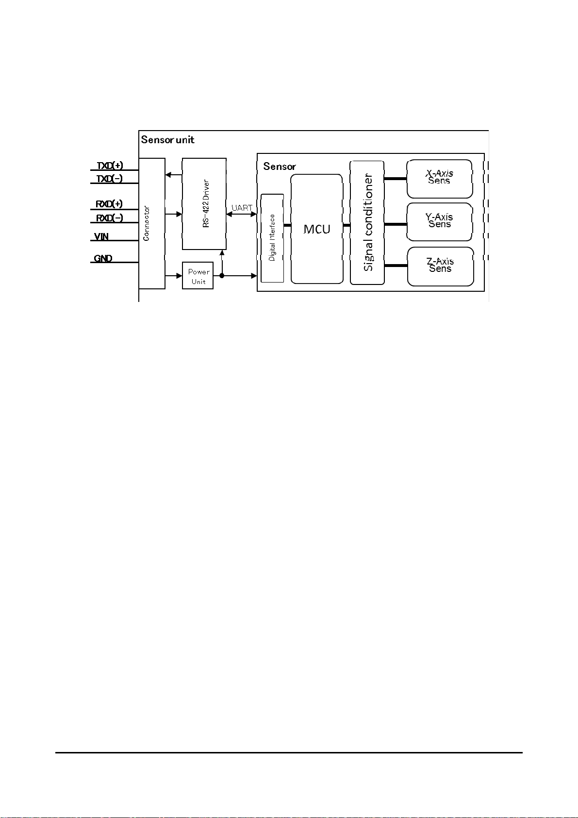
1.2. BLOCK DIAGRAM
Figure 1-1 Block Diagram
4 Seiko Epson Corporation M-A550AR2
Rev.20160704
Page 7

r
*
1
2. SPECIFICATIONS
2.1. ABSOLUTE MAXIMUM RATINGS
Table 2-1 Absolute Maximum Ratings
Parameter Min Typ Max Unit
VIN to GND −0.3 +32 V
Voltage on any pin to GND −7 +12 V
Storage temperature range −20 85 °C
Operating temperature range -20 70 °C
Operating humidity (no condensation) 90 %R.H.
Storage humidity (no condensation) 90 %R.H.
Acceleration / Shock (Half-sine 0.5msec) *1 300 G
If the unit is operated beyond the absolute maximum rating, malfunction may occur or the unit may fail
completely. Although the unit may appear to operate normally, reliability may decrease.
CAUTION:
*1
Excessive vibration or shock independent of the above listed conditions may increase the
possibility of malfunction or causing a failure!
2.2. RECOMMENDED OPERATING CONDITION
Table 2-2 Recommended Operating Conditions
Paramete
Power supply voltage VIN VIN to GND *2 9
Port input voltage V
Operating temperature T
*1
When power supply voltage is 9V or less, the master may not be able to communicate with a node
normally even if the LED turns on.
*2
The power supply voltage must reach the recommended operating condition within 2 seconds after
power is applied to a node.
Term Condition Min. Typ Max. Unit
12 24 V
RD+/RD- to GND 3.3 V
PORT
-20 - 70 °C
OPE
M-A550AR2 Seiko Epson Corporation 5
Rev.20160704
Page 8

2.3. PERFORMANCE & ELECTRICAL SPECIFICATIONS
Table 2-3 Sensor Specifications (Common Items)
VIN=12V, ±1G unless otherwise noted
Parameter Test Conditions / Comments Min Typ Max Unit
Data output rate *1 500 sps
Frequency range TA=25°C, -3dB down 50 Hz
Misalignment from
mechanical reference
Temperature resolution *2
*1
The data output rate can be changed by user command.
*2
The temperature output is a reference value used for the internal temperature correction, an
-0.5 +0.5 deg
0.001 °C/LSB
d is not guaranteed to accurately output the interior temperature.
Table 2-4 Sensor Specifications (Acceleration)
VIN=12V, ±1G unless otherwise noted
Parameter Test Conditions / Comments Min Typ Max Unit
Detection range *1
Input range *2
Reduced accuracy operating
Accuracy guaranteed by
specification
-5 +5 G
-1 +1 G
Resolution +/-0.06 uG/LSB
Data temperature
Misalignment between
axes
-20~70°C
-4 4 mG
TA=25°C -0.1 +0.1 deg.
Nonlinearity TA=25°C, ±1G -0.03 +0.03 %
Noise density
*1
The range from above ±1G to ±5G is outside the guaranteed accuracy specification.
*2
The calibrated standard 1G gravitational acceleration value is 9.80665 m/s
TA=25°C, average 0.5Hz to 6Hz 0.5 2 uGrms/√Hz
TA=25°C, peak 0.5Hz to 100Hz 60 uGrms/√Hz
2
.
Table 2-5 Sensor Specification (Tilt Angle)
VIN=12V, ±45deg unless otherwise noted
Parameter Condition / Comment Min Typ Max Unit
Input Range *1 Reduced accuracy operating range -1.047 +1.047 rad
Input Range *2 Accuracy guaranteed by specification -0.785 +0.785 rad
Null Offset
Repeatability
Null Offset
TA=25°C and VCC=3.3V for one year after
±3.491 mrad
shipment
-20°C to +85°C -4.014 +4.014 mrad
Temperature
Variation
Axis Alignment
TA=25°C -1.745 +1.745 mrad
Error
Non-Linearity TA=25°C,±45deg. -0.03 +0.03 %
Noise Density TA=25°C, average 0.5Hz to 6Hz, horizontal 0.5 2 µrad/√Hz
6 Seiko Epson Corporation M-A550AR2
Rev.20160704
Page 9
p
p
Parameter Condition / Comment Min Typ Max Unit
Resolution 0.002 µrad/LSB
NOTE: The Max/Min value is the maximum/minimum value of the design or factory shipment
examination, unless otherwise specified.
*1
The range between ± 45deg to ± 60deg is outside the guaranteed accuracy specifications.
*2
The calibrated standard 1G gravitational acceleration value is 9.80665 m/s2.
The tilt angle is internally calculated from gravitational acceleration by the following expression.
Tilt Angle Calculation Formula
][ asin(G) rad
Table 2-6 Sensor Specification (Tilt Angle Speed)
Condition: T
=-20°C ~ +85°C, VCC=3.15V to 3.45V, and ±45deg, unless otherwise specified.
A
Parameter Condition/Comment Min Typ Max Unit
Calculation
Range
Unitpermillisecondofmeasurementtrigger ‐2.094 +2.094 rad/ms
Unitpersecondofmeasurementtrigger ‐2.094 +2.094 rad/s
Resolution Unitpermilli‐secondofmeasurementtrigger 2 (µrad/s)/LSB
Unitpersecondofmeasurementtrigger 0.002 (µrad/s)/LSB
NOTE: The Max/Min value is the maximum/minimum value of the design or factory shipment
examination, unless otherwise specified.
The tilt angle speed is a change of the tilt angle per unit time between the measurement intervals.
The tilt angle is internally calculated by the following expression.
Tilt Angle Speed Formula
)(
01
: Present tilt angle
1
: Tilt angle measured in previous sample
0
OutputRate_ms: Value of measurement interval by internal timer when command was set. Unit [ms] of measurement trigger.
OutputRate_s: Value of measurement interval by internal timer when command was set. Unit [s] of measurement trigger.
)(
01
1
_
msOutputRate
1
_
sOutputRate
]/[
msrad
]/[
srad
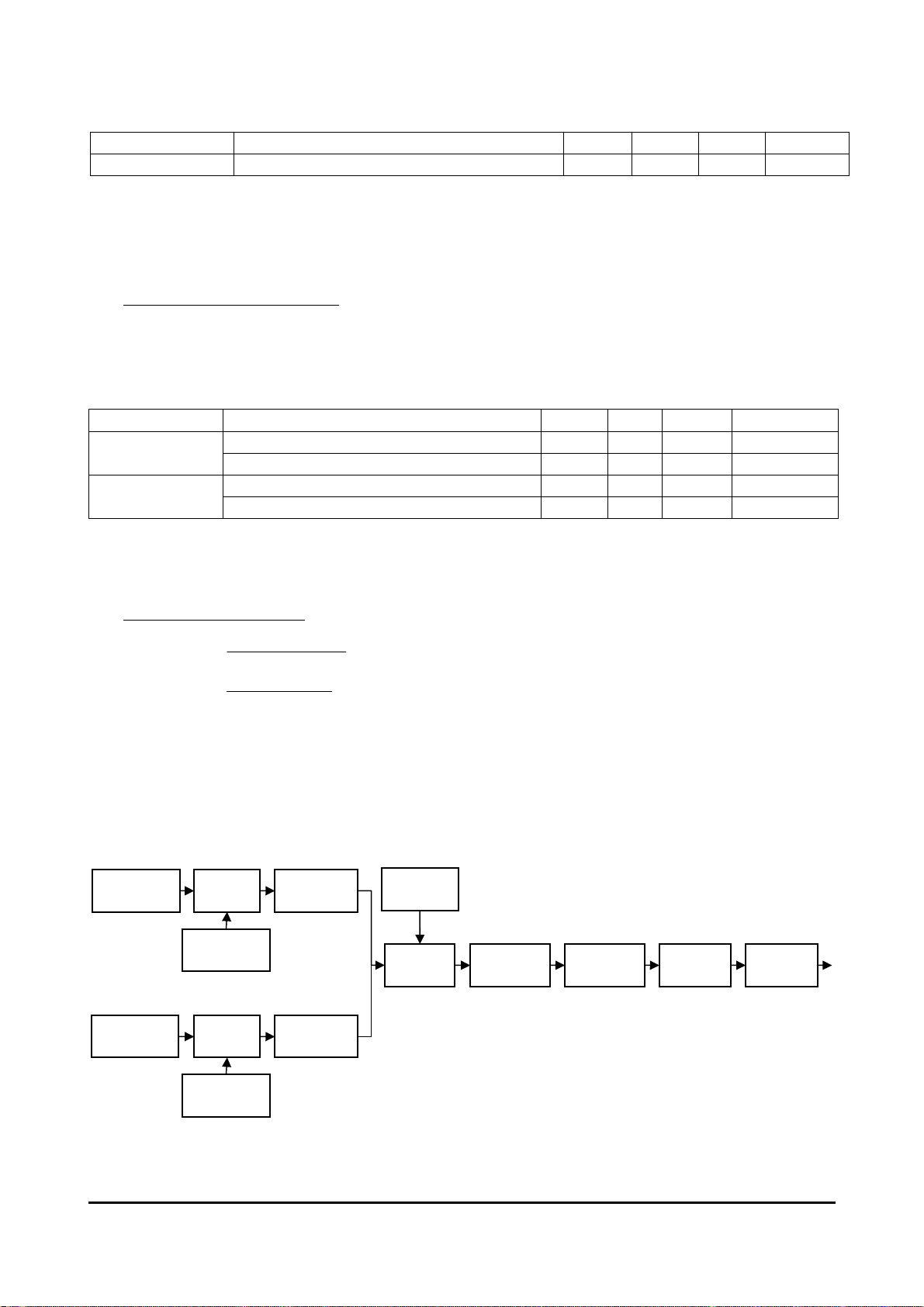
SENSOR
Accelerometer
SENSOR
Temperature
Sampling
Internal Clock
4k Sps/ch
Sampling
Internal Clock
1k Sps
FIR Filter
Moving
Average Filter
128ta
External trg.
Down
Sampling
Out
ut rate
Convert into
Temperature
Temperature
Correction
Alignment
Correction
Format
Conversion
RS422(UART)
Figure 2-1 Functional Block Diagram
Table 2-7 Interface Specification
M-A550AR2 Seiko Epson Corporation 7
Rev.20160704
Page 10

*2
TA=25°C, VIN=12V, unless otherwise noted
Parameter Test Conditions Min Typ Max Unit
Driver
Differential Output
Voltage
Common Mode Output
Voltage
Driver Short-Circuit
Current
Rise or Fall Time RL=100Ω 400 ns
Receiver
Input Resistance 100 Ω
Receiver Differential Input
Threshold Voltage
Receiver Input Hysteresis RD- =0V 25 mV
FUNCTIONAL TIMES Time until data is available
Power-On Start-Up Time
*1
Re-Initialization Time Reboot by a command*1 0.7 s
Measurement Wait Time
Command Response Time
*1
The device must not be accessed during initializing.
*2
The device should not be triggered to measure until the elapsed time immediately after the start of measurement.
*3
The measurement interval by the request command must be 500Sps or less.
*4
The timeout period from the last character reception to the “LF" reception. Following a timeout condition, the device issues an
error code response of “#".
RL=100Ω,TD- to TD+ 2 3.3 V
RL=OPEN, TD- to TD+ 3.3 V
RL=100Ω 3 V
-7V=<TD*=<12V -250 300 mA
-7V < RD- < 12V -0.2 0.2 V
*1
Include Initialization
1) REQDAT command Response
2) TSTSLF command Response
3) Command reception timeout
Response except for 1),2),3)
2.0 s
220
*3
1.3 ms
600 ms
*4
520 ms
4 ms
Table 2-8 Current Consumption
Ta=25°C,RL=100
Ω,unless otherwise specified; all voltages are defined with respect to ground; positive
currents flow into the sensor unit.;
Parameter Term Condition Min. Typ Max. Unit
Idle state I
Vin=12V - 10 - mA
IN(ready)
Vin=24V - 5 - mA
Continuous
measurement
mode
Maximum input
Vin=12V - 16 - mA
I
IN(op)
Vin=24V - 10 - mA
I
- - 60 mA
IN(max)
current
8 Seiko Epson Corporation M-A550AR2
Rev.20160704
Page 11
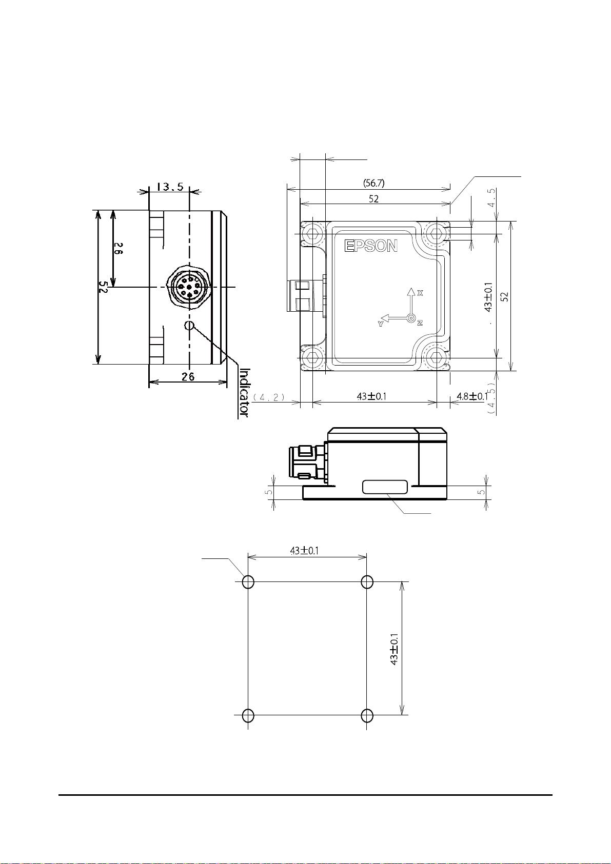
3. MECHANICAL DIMENSIONS
3.1. OUTLINE DIMENSIONS
9(max)
Referen ce Pla n e
4.2
Seria l No .
Figure 3-1 Outline Dimensions (millimeters)
4-M4
Figure 3-2 Recommended Mounting Dimension
M-A550AR2 Seiko Epson Corporation 9
Rev.20160704
Page 12
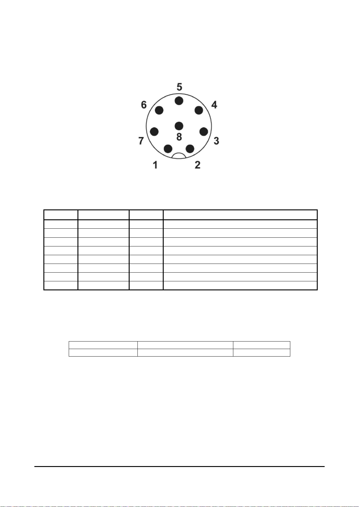
3.2. CONNECTOR SPECIFICATIONS
Figure 3-3 Connector Pin Terminal
Table 3-1 Pin Function Description
Pin No. Mnemonic Type*1 Description
1 NC N/A Do Not Connect
2 VIN S Power Supply (9-30V)
3 GND S 0V
4 TD- O Transmit Data (-)
5 RD+ I Received Data (+)
6 TD+ O Transmit Data (+)
7 NC N/A Do Not Connect
8 RD- I Received Data (-)
*1) Pin Type I :Input, O :Output, I/O :Input/Output, S :Supply, N/A :Not Applicable
Note: Please use an M12-8 pin mating female connector that corresponds to IP67 specifications.
Table 3-2 describes the connector manufacturer and the model number which is used in this
product.
Table 3-2 Conector Part Number
Manufacturer Part Number RoHS Compliant
PHOENIX CONTACT SACC-DSI-MS-8CON-M12-SCO SH
Yes
10 Seiko Epson Corporation M-A550AR2
Rev.20160704
Page 13
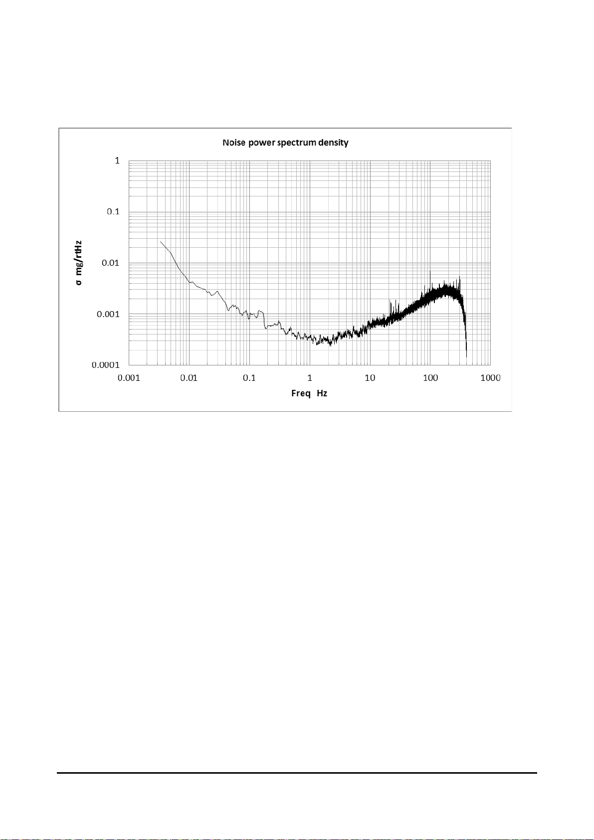
4. TYPICAL PERFORMANCE CHARACTERISTICS
Figure 4-1 Noise Density Characteristics
The above graph is a typical example of the product characteristics, and is not guaranteed by the
specification.
M-A550AR2 Seiko Epson Corporation 11
Rev.20160704
Page 14
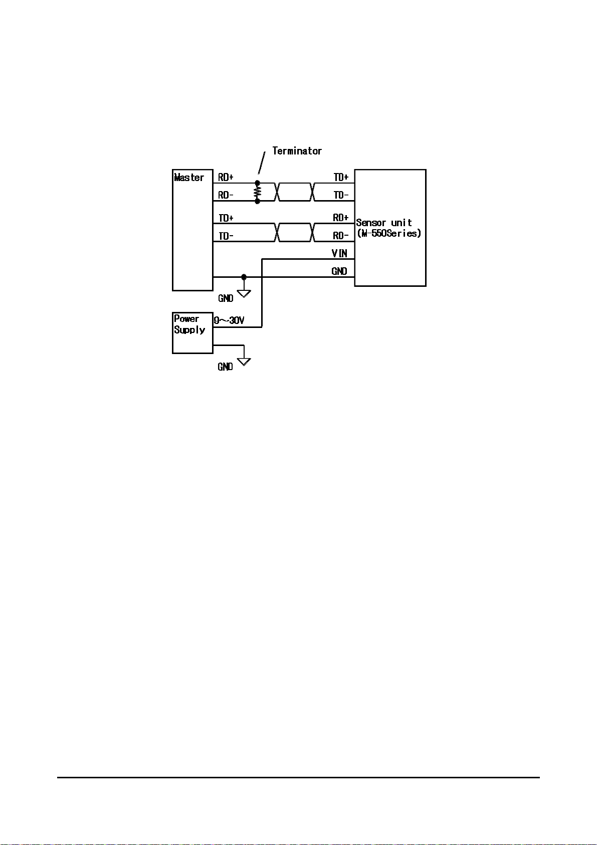
5. CONNECTION EXAMPLE
5.1. CONNECTION TO HOST
Figure 5-1 Connection Example
5.2. PRECAUTION FOR WIRING AND CABLING
・ This product has internal terminator on the receiver port (RD).
・ It is recommended that twisted pair cable with shielding should be used. Each signal pair should
be connected to each cable pair. (ex: RD+ and RD-)
・ It is recommended that shield connects to ground (at the host) when a cable with shield is used.
・ Maximum recommended cable length is 250 meters as a guideline. However, even if the cable
length is within the guidelines, the communication may be unstable or unusable depending on
system environment. The cabling should be evaluated in the target system environment to
confirm proper operation. (Ref: TIA-EIA-422-B ANNEX A)
5.3. PRECAUTION FOR SUPPLYING POWER
・ The user should be aware of serious risks on the power supply exposure to the following:
High voltage noise by increased resistance and inductance on power supply line.
Surge voltage from lightning and environmental equipment.
・ Figure 5-2 describes reference protection circuit against the lightning surge with a surge level
based on IEC61000-4-5, +/-1kV(power supply line to the power supply ground) and
+/-2kV(power supply line to the earth).
VP: CAN_V+ (Power supply)
PGND: CAN_GND (Power supply ground)
FGND: EARTH (System ground earth)
U3039: Surge absorber to line (Okaya Electric Industries)
ERZ-V14D390: Surge absorber to ground (Panasonic)
12 Seiko Epson Corporation M-A550AR2
Rev.20160704
Page 15
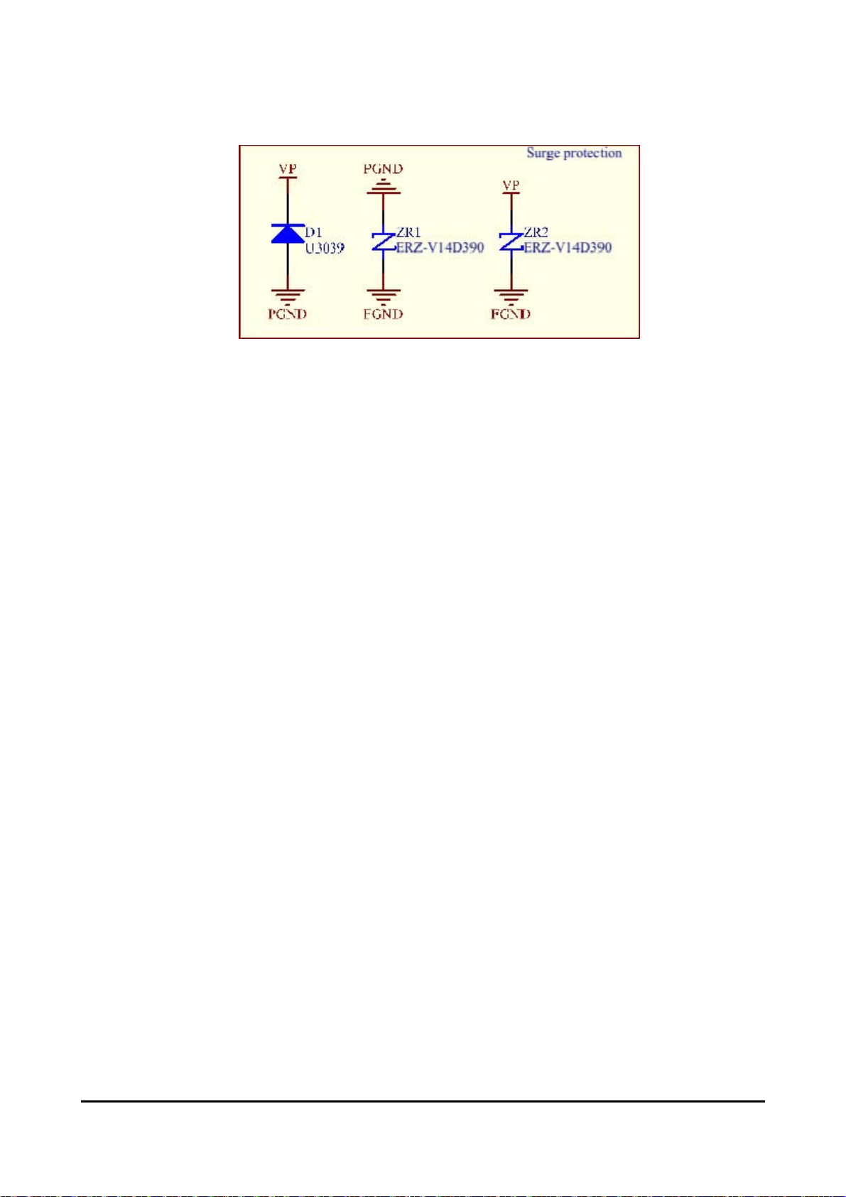
Figure 5-2 Surge Protection Circuit
M-A550AR2 Seiko Epson Corporation 13
Rev.20160704
Page 16

(
(
(
N
(
6. BASIC OPERATION
6.1. OPERATION MODE
The following operational modes are available in the device.
IDLE mode
CONFIG mode
MEASUREMENT mode
The transitioning between these modes are controlled by AT commands in the RS422(UART)
interface. Please refer to Chapter 6 for details of the interface.
6.1.1. STATE TRANSITION
The sensor device starts an internal initialization immediately after power is supplied. After
initialization completes, the device enters IDLE Mode. The device transitions to various
operational modes by executing commands sent by the host. The state transition chart is
described as below.
Write to NVRAM
Received write command
in CONFIG mode.
Initialization
ot receive write command
in CONFIG mode.
ATENDCFG
(0xA5,0x00)
Configuration
ATWRDTRG (0xA0-0xA1)
ATWRUART (UART only)
ATWRDFRM (0xA3)
ATWDPYCL (0xA4)
ATWRFILT (0xA8)
ATWRAUTO (0xA3)
ATWRBIAS (0xD7-0xD2)
Write to RAM
Power ON
/ RESET
Internal
IDLE
MODE
ATCONFIG
0xA5,0x02)
MODE
Soft Reset
0xE0,0x01 : SPI only)
ATRDTRG (0x20-0x21)
AT R D U ART (U A RT onl y )
ATRDMODL (0x4C-0x30)
ATRDFVER (0x50-0x4D)
ATTSTSLF (0x51)
ATRDFRM (0x23)
ATRDPYCL(0x24)
ATRDFILT (0x28)
ATRDAUTO (0x23)
ATRDBIAS (0x57-0x52)
Read RAM
Data Output
UART : AT COMMAND
Host to M-A550
Measurement
STOP
ATENDMES
(0xA5,0x00)
ATREQDAT
Measurement
0xA5,0x13)
Measurement
START
Continuous
MODE1
Internal Timer
/ External Trigger
Data Output
AT MES MD 1
0xA5,0x11)
Auto Measure = Enable
Only at Power ON
CONFIG MODE
MEASUREMENT MODE
Figure 6-1 State Transition Diagram
14 Seiko Epson Corporation M-A550AR2
Rev.20160704
Page 17

6.1.2. INITIALIZATION INDICATION FUNCTION
The device enters initialization immediately after power-on/reset, receives a software reset
command, or after exiting CONFIG mode (ATENDCFG/MODE_CTRL) while receiving a write
command when in CONFIG mode. Refer to Figure 6-1 State Transition Diagram for the
processing sequence.
The device will send a response with "Init.M-A351<CR><LF>" to the host after initialization
ends.
VIN
Initialization
RXD(RS-422)
Typ.2.6s
Data Ready
TXD(RS-422)
“Init.M-A351”
Reboot by the command
MODE_CTRL / ATENDCFG
Typ.1s
“Init.M-A351”
Figure 6-2 Initialization Indication Diagram
6.1.3. BIAS CORRECTION FUNCTION
The device includes a bias correction function which allows the user to apply a fixed bias (offset)
correction to the acceleration value by user command. The correction value has a range of
-32767 to +32767 uG that is added to the measured acceleration value before output to the host.
The host should set the correction value to “0" (initial value) when not using the bias correction
function.
6.1.4. OUTPUT UNIT SELECT FUNCTION
The device includes an output unit select function which allows the user to individually select for
each axis between 3 output unit types by user command: acceleration (initial value), tilt angle, or
tilt angle speed. This individual select function for each axis is available in compound
measurement mode. The tilt angle and tilt angle speed are internally calculated from the
measured gravitational acceleration value. Please refer to Section 2.3 for a description of the
formula for computation.
6.1.5. OPERATION MODE DESCRIPTION
1) Measurement Mode 1
In Measurement Mode 1, the internal measurement circuits are enabled. To enter Measurement
Mode 1, the device must be in IDLE mode and the host sends the command UART:
“ATMESMD1<CR><LF>”.
If the measurement trigger is set to internal timer, the device will send measured acceleration
results at the programmed time interval. The measurement begins immediately after the internal
timer trigger event and a short measurement latency delay.
M-A550AR2 Seiko Epson Corporation 15
Rev.20160704
Page 18

While in Measurement Mode 1, the host can manually request measured acceleration results by
sending commands UART: ATREQDAT<CR><LF>.
To exit Measurement Mode 1 and move to IDLE mode, the host can send the command UART:
ATENDMES <CR><LF>.
Automatic Measurement Mode
After power on, the device will automatically shift to Measurement Mode 1, if automatic
measurement setting is enabled (without the host sending a command to enter Measurement Mode
1). After entering Measurement Mode 1 automatically, the device can accept commands as normal.
2) Configuration Mode
Configuration Mode allows the host to program or read device information / measurement
conditions such as internal timers, filter settings, or device manufacturing information. To enter
Configuration Mode, the device must be in IDLE mode and the host sends the command UART:
“ATCONFIG<CR><LF>”.
As an example when in Configuration Mode, if the host sends UART: “ATRDDTRG<CR><LF>” to
the device to read the current trigger setting, and the following result is returned
“DTRG=2,00005,0<CR><LF>” and “<CR><LF>OK<CR><LF>”. The device is currently set for
measurement trigger from internal timer with a measurement interval value of 5 ms.
6.2. INTERNAL FILTER
The device has programmable internal FIR filter. The FIR filter setting can be set using the WRFILT
command to program the FILTER_CTRL register. This filter uses a Kaiser Window with selectable
filter TAP (128, 256, or 512), and cutoff frequencies (fc=5, 10, 20, 50Hz). Refer to Figure 6-4 ~ Figure
6-7 to see the typical filter characteristics and output rate considerations.
Table 6-1 Internal Filter Cutoff Bandwidth
Parameter Condition Min Typ Max Unit
Filter bandwidth -3dB, 512Tap 121 Hz
Figure 6-3 FIR Kaiser Filter Characteristic (Tap512)
16 Seiko Epson Corporation M-A550AR2
Rev.20160704
Page 19

Figure 6-4 FIR Kaiser Filter Characteristic (Fc=5Hz)
Figure 6-5 FIR Kaiser Filter Characteristic (Fc=10Hz)
Figure 6-6 FIR Kaiser Filter Characteristic (Fc=20Hz)
M-A550AR2 Seiko Epson Corporation 17
Rev.20160704
Page 20

Figure 6-7 FIR Kaiser Filter Characteristic (Fc=50Hz)
18 Seiko Epson Corporation M-A550AR2
Rev.20160704
Page 21

r
The host must set the cutoff frequency of the FIR filter and the output rate in proper combination to
avoid aliasing. The RS422 interface supports an output rate of 500Sps.
Filte
F
Loss
Fs: Sampling frequency
Fn = fs/2: Nyquist frequency
Fc: Filter cutoff frequency
Magnitude
f
fn
0 fs
c
Frequency
Figure 6-8 Anti-Aliasing Relationship Diagram
Table 6-2 Supported Settings Output Rate and Filter Cutoff Frequency
Filter
512Tap
Filter
256Tap
Filter
128Tap
Group
delay
100Hz
50Hz × ○ × × ×
20Hz × ○ ○ × ×
10Hz × ○ ○ ○ ×
5Hz × ᇞ ᇞ ᇞ ᇞ
100Hz
50Hz × ○ × × ×
20Hz × ᇞ × × ×
10Hz × ○ ○ × ×
5Hz × ᇞ ᇞ ᇞ ×
100Hz
50Hz × ○ × × ×
20Hz × ᇞ × × ×
10Hz × ᇞ × × ×
5Hz × ᇞ ᇞ × ×
63.9ms
31.9ms
15.9ms
1000Sps 500Sps 200Sps 100Sps 50Sps
× × × × ×
× × × × ×
× × × × ×
Output Rate
○: F
ᇞ: F
< -120dB Recommended setting
Loss
< -60dB Although a possible setting, some decrease in measurement quality due to aliasing
Loss
×: Fn < Fc Invalid setting. The measurement data responds with error “0x64000000".
M-A550AR2 Seiko Epson Corporation 19
Rev.20160704
Page 22

7. HOST INTERFACE
This product can be controlled by AT commands by serial communication interface. Details of the AT
commands and parameters are described in this section.
7.1. SERIAL INTERFACE SPECIFICATION
7.1.1. COMUNICATION CONDITION
Table 7-1 UART Communication Settings
Parameter Supported Values
Transfer Rate 57.6 kbsp / 115.2kbps / 230.4kbps / 460.8kbps (Selectable by command)
Start 1bit
Data 8bit (LSB First)
Stop 1bit/ 2bit (Selectable by command)
Parity None/ Even/ Odd (Selectable by command)
7.1.2. COMMAND SEQUENCE
This device responds to all commands received from the host with a result code. The host must
wait to receive the result code from the previous command before issuing the next command.
When the sensor unit is in measurement mode with internal timer triggering, this device keeps
sending the sensor data at the user programmed timer interval until the measurement end
command is received to go to IDLE mode.
Application
(HOST)
Command
Result Code
(1) Basic Sequence
Accelerometer
(M-A351)
Application
(HOST)
Command
Result Code
Sensor Data
Sensor Data
Sensor Data
(2) Measurement Sequence
(Internal Timer)
Accelerometer
(M-A351)
Figure 7-1 Command Sequence
20 Seiko Epson Corporation M-A550AR2
Rev.20160704
Page 23

7.1.3. COMMAND DESCRIPTION
The following describes the list of available commands and functions. All commands must be
pre-fixed or start with ”AT” and terminated or end with “<CR><LF>". All result codes returned
from the sensor unit to the host is either:
“<CR><LF>OK<CR><LF>” to indicate success.
“<CR><LF>#<CR><LF>" to indicate failure.
1) Available command during IDLE mode
Command
Function
Explanation
MESMD1
Go to Measurement Mode1.
Set device to Measurement Mode 1. When a request for sensor data is triggered,
data is transmitted to the host.
Return
<Result> OK (success)
# (failure)
Command CONFIG
Function Go to Configuration Mode.
Explanation Set device to CONFIG Mode to allow reading or writing device settings.
Response
<Result> OK (success)
# (failure)
2) Available commands in Measurement Mode1
Command
REQDAT
Function Request sensor data transmission.
Explanation The latest measurement data is sent to the host.
- The maximum request rate is 500Sps.
- Refer to Section 6.2 INTERNAL FILTER, to ensure the FIR filter is valid
according to Table 6-2 Supported Settings Output Rate and Filter Cutoff
Frequency to avoid aliasing.
Response
Refer to section 7.1.4 for the output format of the sensor data
Command
Function
ENDMES
End Measurement Mode 1.
Explanation
The device stops measurement operation, and goes to IDLE mode.
Response
<Result> OK (success)
# (failure)
M-A550AR2 Seiko Epson Corporation 21
Rev.20160704
Page 24

3) Available commands in Configuration mode :
Format RDMODL
Function Read the device model and other device manufacturing information.
Explanation The device sends model name, date of manufacture, and serial number.
MODL=<Model>,<yymmdd>,<SerNo>
<Result>
<Model> Model name
<yymmdd> Date of manufacture
<SerNo> Serial number
<Result> OK (success)
# (failure)
Response
Format RDFVER
Function Read the firmware version.
Example:
Model name = M-A351AU
Date of Manufacture = October 8, 2014
Serial number = 12345678
Device Output:
MODL = MA351AU, 141008, 12345678-*******
OK
Explanation The device sends the firmware version number.
FVER=<FVer>
<Result>
<FVer> Firmware version number
<Result> OK (success)
# (failure)
Response
(Example Case)
Firmware version number = 1.00
(Device Output)
FVER=1.00
OK
Format RDDTRG
Function Read the setting for sensor data transmission trigger.
Explanation
The device sends the current trigger source setting including the timer interval
value.
22 Seiko Epson Corporation M-A550AR2
Rev.20160704
Page 25

DTRG=<Trg>,<Intval>,<Unit>
<Result>
<Trg> Trigger source 0: None
1: Invalid (External trigger)
2: Timer
3: Timer (External trigger is disabled)
<Intval> Measurement Interval Unit of [s] seconds
00001~00060
Unit of [ms] millisecond
Response
00002 : 500Sps
00005 : 200Sps
00010 : 100Sps
00020 : 50Sps
<Unit> Time unit 0: [ms] milliseconds
1: [s] seconds
<Result> OK (success)
# (failure)
Format WRDTRG=<Trg>,<Time>,<Unit>
Function Write the setting for sensor data transmission trigger.
The host writes the specified parameters <Trg>, <Intval>, and <Unit> to the
device.
<Trg> Trigger source 0: None
1: Invalid (External trigger)
2: Timer
3: Timer (External trigger is disabled)
<Intval> Measurement Interval Unit of [s] seconds
00001~00060
Unit of [ms] millisecond
00002 : 500Sps
Explanation
00005 : 200Sps
00010 : 100Sps
00020 : 50Sps
<Unit> Time unit 0: [ms] milliseconds
1: [s] seconds
- Refer to Section 5.3, to ensure the FIR filter setting is valid according to
Table 5.3 Supported Settings Output Rate and Filter Cutoff Frequency to
avoid aliasing.
- When the Time unit is [s] seconds, the device internally downsamples to
50Sps (512Tap), and performs the following averaging process depending on
the measurement interval setting, except in the case when timer
measurement will output the latest value without averaging as in Note 1.
M-A550AR2 Seiko Epson Corporation 23
Rev.20160704
Page 26

Format WRDTRG=<Trg>,<Time>,<Unit>
1 ~ 10s: The averaging process uses the sensor data from the entire timer
interval.
11 ~ 60s: The averaging process uses the most recent 500 samples of sensor
data before the timer interval.
NOTE: The measurement interval is limited by the relationship with the UART
communication speed. Refer to the restrictions in Note 2 located after the
WRUART command description.
NOTE: The measurement interval is used to calculate the tilt angular speed
regardless of the measurement trigger conditions.
Response
<Result> OK (success)
# (failure)
NOTE 1: Averaging Process Output When Timer is Measured in Unit [s] Seconds
Intval (1~10s)
Down Sampling
50Sps
Average
RXD(UART)
Measurement data
Figure 7-2 Averaging Process Output When Timer Interval is 1-10s
Intval (10~60s)
Down Sampling
50Sps
Average
RXD(UART)
Measurement data
10s
Measurement data
Figure 7-3 Average Process Output When Timer Interval is 10-60s
24 Seiko Epson Corporation M-A550AR2
Rev.20160704
Page 27

Format RDUART
Function Read the device UART setting.
Explanation The device sends the UART setting (baud rate, parity bit, and stop bit).
UART=<BaudRate>,<ParityBit>,<Stop>
<Result>
Response
<BaudRate> Transmission rate
<ParityBit> Parity bit
<Stop> Stop bit
<Result>
57600 (57.6kbsp)
115200 (115.2kbps)
230400 (230.4kbps)
460800 (460.8kbps)
N (None)
E (Even)
O (Odd)
1 (one bit)
2 (two bits)
Format WRUART=<BaudRate>,<ParityBit>,<Stop>
Function Write the setting for UART transmission.
The host writes the specified parameters <BaudRate>, <ParityBit>, and <Stop> .
57600 (57.6kbsp)
115200 (115.2kbps)
230400 (230.4kbps)
460800 (460.8kbps)
N (None)
E (Even)
O (Odd)
1 (one bit)
2 (two bits)
Explanation
<BaudRate> Transmission rate
<ParityBit> Parity bit
<Stop> Stop bit
NOTE: These UART settings take effect after receiving the "ENDCFG" command
to exit Configuration Mode.
Response
<Result> OK (success)
# (failure)
NOTE 2: Sensor Data Transmission Cycle and UART Transmission Rate
The time required to transmit is different according to the number of output axes and the UART
transmission rate. Please refer to Table 6.2 when configuring the transmission rate.
M-A550AR2 Seiko Epson Corporation 25
Rev.20160704
Page 28

Table 7-2 UART Baud Rate and Sensor Data Transmission Cycle
Transmission
Rate (bps)
57600 10
115200 5
230400 2
460800 2
Minimum Measurement
Interval (msec)
Based on UART transmission setting:
Stop bit =1, Parity =None
Based on output condition:
Outputs three axes, and temperature
Format ENDCFG
Function End Configuration mode.
The device exits Configuration mode.
While in CONFIG mode, if any “WR****”commands were received before the
Explanation
ENDCFG command, the device will write the settings to non-volatile memory,
perform an internal initialization, and go to IDLE mode.
If no "WR****" command was received, the device goes immediately to IDLE
mode.
Response
<Result> OK (success)
# (failure)
Format TSTSLF
Function Initiate a self-diagnosis test, and send the result.
The device performs a self-diagnosis test and the results are sent.
The following diagnostic outcomes are sent for each test.
Refer to Note 3 for description of the self-diagnostic tests.
Test Number Test Description
Explanation
1 Power-supply voltage
2 Non-volatile RAM
3 Reference clock
4 Acceleration sensor
5 Temperature sensor
6 Built-in RAM
< Result > Judgment + Test Number
Judgment O: OK
Response
N: NG
Example:
"O3" means no failure was detected on the Reference Clock test
"N4" means a failure was detected in the Acceleration sensor test
NOTE 3: Self-diagnosis Test Description
The following describes the details of the self-diagnosis tests.
1. Power-supply voltage
The result of the self-test on the power-supply voltage is shown. The internal power-supply
voltage for sensor device is confirmed to be approximately within the range of 3.0~3.6V.
26 Seiko Epson Corporation M-A550AR2
Rev.20160704
Page 29

2. Non-volatile RAM
The result of a self-test on the non-volatile RAM(EEPROM) is shown. The checksum result of
data in non-volatile RAM is correct.
3. Reference clock
The result of the self-test on the 32.768kHz & 32MHz quartz oscillator for the control IC is
shown. The frequency of 32MHz is compared relative to the 32.768kHz quartz oscillator for
frequency tolerance within ±400ppm.
4. Acceleration sensor
The result of the self-test of the acceleration sensor is shown. The synthesized value of the
acceleration sensor vector for the X, Y, and Z axis under the static conditions is confirmed to be
approximately in the range of 0.8~1.2G.
5. Temperature sensor
The result of the self-test on the temperature sensor is shown.
6. Built-in RAM
The result of the self test on the built-in RAM is shown. A write and read verification of RAM is
confirmed. This test is only performed at device startup.
Format RDDFRM
Function Read the sensor data output format.
Explanation
Response
The device sends the current sensor data output format (model, temperature
output, and output axis).
DFRM=<Model>,<Temp>,<Axis>
<Result>
<Model> Model Type
<Temp> Temperature Output
<Axis> Axis Output Configuration
0: Accelerometer
1: Inclinometer
2: Tilt angle speed
3: Compound measurement
0: Temperature data not included
1: Temperature data included
X: X axis
Y: Y axis
Z: Z axis
XY: X axis + Y axis
XZ: X axis + Z axis
YZ: Y axis + Z axis
XYZ: X axis + Y axis + Z axis
M-A550AR2 Seiko Epson Corporation 27
Rev.20160704
Page 30

Format WRDFRM=<Model>,<Temp>,<Axis>
Function Write the setting for the sensor data output format
The host writes the specified value for each parameter <Model>, <Temp>, and
<Axis>.
Explanation
<Model> Model Type
<Temp> Temperature Output
<Axis> Axis Output Configuration
0: Accelerometer
1: Inclinometer
2: Tilt angle speed
3: Compound measurement
0: Temperature data not included
1: T emperature data included
X: X axis
Y: Y axis
Z: Z axis
XY: X axis + Y axis
XZ: X axis + Z axis
YZ: Y axis + Z axis
XYZ: X axis + Y axis + Z axis
Response
<Result> OK (success)
# (failure)
Format RDPYCL
Function Read sensor data physical output setting when compound output is selected.
Explanation
The device sends the physical output format for each axis when compound output
(acceleration, tilt angle, and tilt angle speed) is set.
PYCL=<X-PhyQ>,<Y- PhyQ>,<Z- PhyQ>
<Result>
Response
< X- PhyQ> X axis physical output format
< Y- PhyQ> Y axis physical output format
< Z- PhyQ> Z axis physical output format
0: Acceleration
1: Tilt angle
2: Tilt angle speed
0: Acceleration
1: Tilt angle
2: Tilt angle speed
0: Acceleration
1: Tilt angle
2: Tilt angle speed
Format WRPYCL=<X- PhyQ>,<Y- PhyQ>,<Z- PhyQ>
Function
Write the setting for sensor data physical output format when compound output
(acceleration, tilt angle, and tilt angle speed) is set.
28 Seiko Epson Corporation M-A550AR2
Rev.20160704
Page 31

The host writes the specified parameter <*_PhyQ> to set each format of the
sensor data physical output.
0 :Acceleration
1:Tilt angle
2:Tilt angle speed
0 :Acceleration
1:Tilt angle
2:Tilt angle speed
0 :Acceleration
1:Tilt angle
2:Tilt angle speed
Explanation
<X- PhyQ> X axis physical output format
<Y- PhyQ> Y axis physical output format
<Z- PhyQ> Z axis physical output format
NOTE: These settings are effective only when compound output is selected.
Response
<Result> OK (success)
# (failure)
Format RDFILT
Function Read the internal FIR filter setting.
Explanation
The device sends the internal FIR filter setting such as filter type, cutoff frequency,
and number of taps.
FILT=<Type>,<Fc>,<Tap>
<Result>
<Type> Filter type
<Fc> Cutoff frequency
Response
<Tap> Number of taps 128, 256, or 512
Format WRFILT=<Type>,<Fc>,<Tap>
0 : Reserved
1 : FIR Kaiser Filter(fixed)
0 : 5Hz
1 : 10Hz
2 : 20Hz
3 : 50Hz
Function Write the setting for the internal FIR filter.
M-A550AR2 Seiko Epson Corporation 29
Rev.20160704
Page 32

The host writes the specified value of the parameter <Type>, <Fc>, and <Tap> to
the internal FIR filter.
<Type> Filter type
Explanation
<Fc> Cutoff frequency
<Tap> Number of taps 128, 256, or 512
- Refer to Section 5.3, to ensure the FIR filter setting is valid according to Table 5.3
Supported Settings Output Rate and Filter Cutoff Frequency to avoid aliasing.
- When <Unit> Time unit setting for the data transmission trigger is in [s]
seconds, the FIR filter is fixed to 5Hz cutoff frequency/512Tap and averaging
process output is enabled on the output.
0 : Reserved
1 : FIR Kaiser Filter (fixed)
0 : 5Hz
1 : 10Hz
2 : 20Hz
3 : 50Hz
Response
<Result> OK (success)
# (failure)
Format RDAUTO
Function Read the status of automatic measurement mode.
Explanation
The device sends the status of automatic measurement mode (enters
measurement mode automatically after power on).
AUTO=<Auto>
Response
<Result>
<Auto> Automatic measurement mode is ON
OFF
Format
WRAUTO=<Auto>
Function Write the setting to enable/disable automatic measurement mode.
The host writes to enable or disable entering measurement mode automatically
after power supply starts by specifying the parameter <Auto>.
Explanation
<Auto> Automatic Measurement mode is ON
OFF
Response
<Result> OK (success)
# (failure)
30 Seiko Epson Corporation M-A550AR2
Rev.20160704
Page 33

Format RDBIAS
Function Read the bias correction value.
Explanation The device sends the value of the bias correction for each axis.
BIAS=<X_Bias>,<Y_Bias>,<Z_Bias>
<Result>
Response
< X_Bias> X axis bias correction value -32767 ~ 32767 (unit=uG)
< Y_Bias> Y axis bias correction value -32767 ~ 32767 (unit=uG)
< Z_Bias> Z axis bias correction value -32767 ~ 32767 (unit=uG)
Format WRBIAS=<X_Bias>,<Y_Bias>,<Z_Bias>
Function Write the setting of the bias correction value.
The host writes the bias correction value that will be applied to the sensor
measurement value for each axis by specifying the parameter <*_Bias >.
Explanation
< X_Bias> X axis bias correction value -32767 ~ 32767 (unit=uG)
< Y_Bias> Y axis bias correction value -32767 ~ 32767 (unit=uG)
< Z_Bias> Z axis bias correction value -32767 ~ 32767 (unit=uG)
Response
<Result> OK (success)
# (failure)
M-A550AR2 Seiko Epson Corporation 31
Rev.20160704
Page 34

HOST INTERFACE
7.1.4. COMMAND FORMAT
The output data of the measurement value is in binary format, whereas all other command controls and
responses are in ASCII format.
1) Command Format
The commands messages sent to the device starts with "AT" header and ends with a “<CR><LF>"
trailer. The command and parameter is separated with an "=" (equal sign). In the case the command
includes two or more parameters, the parameters are separated with a “,” (comma) delimiter.
“
“
A
T
COMMAND
"
"
“
=
"
PARAMETER
C R L
F
Figure 7-4 Command Format
2) Result Code
Return Value: "OK (command success)" or "# (command failure)"
The result code is sent by the device in response to commands starts and ends with a
“<CR><LF>".
C R L
F
Result Code
C R L
F
Figure 7-5 Result Code
3) Result Data
Return Value: Responses that do not contain “OK" or “#"
Excluding Measurement Value
The device responds to a command with result data followed by a “<CR><LF>" placed at the end.
Result Data
C R L
F
Figure 7-6 Result Data
Measurement Value
Table 7-3 - Table 7-4 show the output data packet format for the measurement values. The
measurement values (acceleration, tilt angle, tilt angle speed, and temperature) are in binary
format. The host should set the desired physical output value, axis, and temperature configuration
by using the WRDFRM and the WRPYCL command.
32 Seiko Epson Corporation M-A550AR2
Rev.20160704
Page 35

Table 7-3 UART Data Packet Format Example 1
Case: WRDFRM=0, 1, XYZ (output acceleration, temperature, and X+Y+Z axis).
Byte
No.
1 ADDRESS ADDRESS[7:0]
2 DATA_LENGTH DATA_LENGTH[7:0]
3 XACCD_3 XACCD_OUT3 [31:24]
4 XACCD_2 XACCD _OUT2 [23:16]
5 XACCD_1 XACCD_ OUT1 [15:8]
6 XACCD_0 XACCD_ OUT0 [7:0]
7 YACCD_3 YACCD_ OUT3 [31:24]
8 YACCD_2 YACCD _ OUT2 [23:16]
9 YACCD_1 YACCD_ OUT1 [15:8]
10 YACCD_0 YACCD_ OUT0 [7:0]
11 ZACCD_3 ZACCD_ OUT3 [31:24]
Name Bit7 Bit6 Bit5 Bit4 Bit3 Bit2 Bit1 Bit0
HOST INTERFACE
12 ZACCD_2 ZACCD _ OUT2 [23:16]
13 ZACCD_1 ZACCD_ OUT1 [15:8]
14 ZACCD_0 ZACCD_ OUT0 [7:0]
15 TEMP_2 TEMP_OUT2 [23:16]
16 TEMP_1 TEMP_OUT1 [15:8]
17 TEMP_0 TEMP_OUT0 [7:0]
18 CHECKSUM CHECKSUM [7:0]
19 CR 0x0D
20 LF 0x0A
Three axis acceleration data, internal temperature, sensor data of X, Y, and Z are sent.
The UART data packet format is decoded as follows:
ADDRESS
Determines the measurement output format type
Acceleration: 0x80, Tilt angle: 0x81, Tilt angle speed: 0x82, Compound output: 0x83
DATA_LENGTH
Data length of the entire data packet including <CR><LF>
Data length: 20 bytes in this example
*ACCD_*
Measurement data
(1)Acceleration
Unit : G
Two's complement and four byte fixed zero point
bit31 : Sign part
bit30-24 : Integer part
bit23-0 : Fraction part
M-A550AR2 Seiko Epson Corporation 33
Rev.20160704
Page 36

HOST INTERFACE
(2)Tilt angle
Unit : Radian
Two's complement and four byte fixed zero point
bit31 : Sign part
bit30-29 : Integer part
bit28-0 : Fraction part
(3)Tilt angle speed
Unit : Radian per measurement interval
Two's complement and four byte fixed zero point
bit31 : Sign part
bit30-29 : Integer part
bit28-0 : Fraction part
TEMP
Thermal data
Unit : °C
Two's complement and three byte fixed zero point
bit23 : Sign part
bit22-10 : Integer part
bit9-0 : Fraction part
CHECKSUM
Checksum data
The checksum range of data packet is calculated from the end of the address byte up to
start of the checksum byte. The computational method of checksum simply adds the
object data in 8bit (bytes) units, and places the resulting 8-bit sum as checksum data.
NOTE: 0x63000000(+99G) is output when the maximum value of the range of
detection is exceeded, and 0x9D000000(-99G) is output when the
minimum value is exceeded.
NOTE: 0x374AC286(+99°) is output when the maximum value of the range of
detection is exceeded, and 0xC8B53D7A(-99°) is output when
minimum value is exceeded.
Radian/s in case of unit [s] seconds
Radian/ms in case of unit [ms] milliseconds
NOTE: 0x374AC286(+99°) is output when the maximum value of the range of
detection is exceeded, and 0xC8B53D7A(-99°) is output when
minimum value is exceeded.
NOTE: This reference is used for internal temperature correction, and is not
guaranteed for accuracy of the absolute internal temperature.
For example: Because the sum total is "672" when the response data is "14 00 03 1A E5
FF FF D3 E0 01 00 12 F3 00 70 35", checksum becomes "72".
34 Seiko Epson Corporation M-A550AR2
Rev.20160704
Page 37

Table 7-4 UART Data Packet Format Example 2
Case: WRDFRM=1,0,Y (Tilt angle, no temperature, and Y axis output)
Byte
No.
1 ADDRESS ADDRESS[7:0]
2 DATA_LENGTH DATA_LENGTH[7:0]
3 YANGD_3 YANGD_OUT3 [31:24]
4 YANGD_2 YANGD_OUT2 [23:16]
5 YANGD_1 YANGD_OUT1 [15:8]
6 YANGD_0 YANGD_OUT0 [7:0]
7 CHECKSUM CHECKSUM [7:0]
8 CR 0x0D
9 LF 0x0A
Name Bit7 Bit6 Bit5 Bit4 Bit3 Bit2 Bit1 Bit0
HOST INTERFACE
M-A550AR2 Seiko Epson Corporation 35
Rev.20160704
Page 38

SAMPLE PROGRAM FLOW
8. SAMPLE PROGRAM FLOW
The recommended procedure for operate this product is shown below.
8.1. RS422 FLOW
7.1.1 Power-on sequence
1) Power-on.
2) Wait Power-On Start-Up Time. /* Initialization */
3) Result: “Init.M-A351¥r¥n" /* Initialization End */
7.1.2 Read sensor configuration setting
1) Change to config mode from idle mode.
Command: “ATCONFIG¥r¥n"
Result: “¥r¥nOK¥r¥n"
2) Read sensor configuration setting.
Command: “ATRDDTRG¥r¥n"
Result: “DTRG=2,00005,0¥r¥n" /* Ext.Trigger=Disable, Timer=Enable, Interval=5ms(200Sps)
*/
Result: “¥r¥nOK¥r¥n"
Command: “ATRDDFRM¥r¥n"
Result: “DFRM=0,1,XYZ¥r¥n" /* Fomat=XYZ-axis Acceleration output with Temperature */
Result: “¥r¥nOK¥r¥n"
Command: “ATRDFILT¥r¥n"
Result: “FILT=1,2,512¥r¥n" /* Filter type=FIR filter, Fc=20Hz, Tap=512 */
Result: “¥r¥nOK¥r¥n"
Command: “ATRDAUTO¥r¥n"
Result: “AUTO=OFF¥r¥n" /* Auto measure mode OFF */
Result: “¥r¥nOK¥r¥n"
Command: “ATRDBIAS¥r¥n"
Result: “BIAS=0,0,0¥r¥n" /* Bias calibration=X:0uG, Y:0uG, Z:0uG */
Result: “¥r¥nOK¥r¥n"
Command: “ATTSTSLF¥r¥n"
Result: “O1¥r¥n" /* Vdd SelfTest=OK */
Result: “O2¥r¥n" /* NVRAM SelfTest=OK */
Result: “O3¥r¥n" /* Clock SelfTest=OK */
Result: “O4¥r¥n" /* Acc.Sensor SelfTest=OK */
Result: “O5¥r¥n" /* Temp.Sensor SelfTest=OK */
Result: “O6¥r¥n" /* IRAM SelfTest=OK */
3) Change to idle mode from config mode.
Command: “ATENDCFG¥r¥n"
Result: “¥r¥nOK¥r¥n"
7.1.3 Write sensor configuration setting
1) Change to config mode from idle mode.
Command: “ATCONFIG¥r¥n"
Result: “¥r¥nOK¥r¥n"
2) Write sensor configuration setting.
Command: “ATWRDTRG=2,00005,0¥r¥n" /* Ext.Trigger=Disable, Timer=Enable, Interval =5ms(200Sps)
*/
Result: “¥r¥nOK¥r¥n"
Command: “ATWRDFRM=0,1,XYZ¥r¥n" /* Fomat=XYZ-axis Acceleration output with Temperature */
36 Seiko Epson Corporation M-A550AR2
Rev.20160704
Page 39

Result: “¥r¥nOK¥r¥n"
Command: “ATWRFILT=1,2,512¥r¥n" /* Filter type=FIR filter, Fc=20Hz, Tap=512 */
Result: “¥r¥nOK¥r¥n"
Command: “ATWRAUTO=OFF¥r¥n" /* Auto measure mode OFF */
Result: “¥r¥nOK¥r¥n"
Command: “ATWRBIAS=0,0,0¥r¥n" /* Bias calibration=X:0uG, Y:0uG, Z:0uG */
Result: “¥r¥nOK¥r¥n"
3) Change to idle mode from config mode.
Command: “ATENDCFG¥r¥n"
Result: “¥r¥nOK¥r¥n"
4) Wait
Initialization Time. /* Initialization */
5) Result: “Init.M-A351¥r¥n" /* Initialization End */
7.1.4 Measurement Mode1
1) Change to Measurement mode1 from idle mode.
Command: “ATMESMD1¥r¥n"
Result: “¥r¥nOK¥r¥n"
2) Wait Measurement Wait Time.
3) Measurement start.
/* Sensor data are output repeatedly by Internal timer. */
b) Result: HD,DL,X3,X2,X1,X0,Y3,Y2,Y1,Y0,Z3,Z2,Z1,Z0,T2,T1,T0,CS,CR,LF /* Binary data output */
[Request Command]
a) Command: “ATREQDAT¥r¥n".
b) Result: HD,DL,X3,X2,X1,X0,Y3,Y2,Y1,Y0,Z3,Z2,Z1,Z0,T2,T1,T0,CS,CR,LF /* Binary data output */
Repeat from a) to b).
4) Measurement end and change to idle mode from Measurement mode1.
Command: “ATENDMES ¥r¥n"
Result: “¥r¥nOK¥r¥n"
SAMPLE PROGRAM FLOW
/* Write to NVRAM after receiving ENDCFG command.
M-A550AR2 Seiko Epson Corporation 37
Rev.20160704
Page 40

HANDLING NOTES
9. HANDLING NOTES
9.1. CAUTIONS FOR ATTACHING
The product contains quartz crystal oscillator created by microfabrication. Take precaution to
prevent falling or excessive impact. Do not use the product after an accidental fall or it experiences
excessive impact. The possibility of a failure and risk of malfunction from failure increases.
Excessive vibration, shock, continuous stress, or sudden temperature change may increase the
possibility of failure.
Please consult us before the unit is used in an environment where there is acute vibration out of the
measurement band.
The product should be kept powered on for more than 15 minutes to measure with highest
precision and accuracy.
Do not connect the product to the network with the supply voltage turned on.
When attaching the product, ensure that the product is properly mounted to avoid mechanical
stress such as warping or twisting. In addition, ensure appropriate torque is applied when
tightening the screws but not too excessive to cause the mount of the product to deform or break.
Use screw locking techniques as necessary.
When setting up the product, ensure that the equipment, jigs, tools, and workers maintain a good
ground in order not to generate high voltage leakage. Applying over current or static electricity to
the product may be damage the product permanently.
When installing the product, ensure that metallic or other conductive material do not enter the
product. Otherwise, malfunction or damage of the product may result.
If excessive shock is applied to the product when, for example, the product falls, the quality of the
product may be degraded. Ensure that the product does not fall when you handle it.
Before you start using the product to obtain measurements, test it in the actual equipment under
the actual operating environment to confirm proper operation.
When connecting a cable to this product, tighten the screw enough after inserting it completely.
This product may not satisfy IP67 if tightening is insufficient.
Do not use the product in a situation where power is always applied to the joint of connector.
Ensure that the signals are wired correctly with attention to the name and the polarity of each
signal.
Since the product has capacitors inside, inrush current occurs immediately after power-on.
Evaluate in the actual environment in order to check the effect of the supply voltage sag caused by
inrush current in the system.
9.2. OTHER CAUTIONS
This product is water-proof and dust-proof in conformity with IP67. We do not guarantee the
operation of the product when the product is exposed to condensation, dust, oil, corrosive gas (salt,
acid, alkaline, etc), or direct sunlight which surpass IP67. Do not use this product under water.
This product is not designed to be radiation resistant.
Never use this product if the operating condition is over the absolute maximum rating. Otherwise,
permanent damage to the product may result.
If the product is exposed to excessive external noise or other similar conditions, degradation of the
precision, malfunction, or damage to the product may result. The system needs to be designed so
that the noise itself is suppressed or the system is immune to the noise.
This product is not designed to be used in equipment that demands extremely high reliability and
where its failure may threaten human life or property (for example, aerospace equipment,
submarine repeater, nuclear power control equipment, life support equipment, medical equipment,
transportation control equipment, etc.). Seiko Epson Corporation will not be liable for any damages
caused by the use of the product for those applications.
Do not apply shock or vibration to the packing box. Do not spill water over the packing box. Do not
store or use the product in an environment where dew condensation occurs due to rapid
temperature change.
Do not put mechanical stress on the product while it is stored.
38 Seiko Epson Corporation M-A550AR2
Rev.20160704
Page 41

HANDLING NOTES
Do not alter or disassemble the product.
Do not use in water except if it gets temporarily wet based on IP67. This product does not achieve
the sufficient waterproof performance if the the connector is mated incorrectly or that the mating
connector does not satisfy IP67.
The power supply to this product must satisfy the voltage rating within 2 seconds after it is turned
on.
Do not use thinner or similar liquids on this product. When cleaning this product, alcohol may be
used.
It is recommended that this product be installed horizontally (±5deg.) for normal use.
9.3. LIMITED WARRANTY
The product warranty period is one year from the date of shipment.
If a defect due to a quality failure of the product is found during the warranty period, we will
promptly provide a replacement.
M-A550AR2 Seiko Epson Corporation 39
Rev.20160704
Page 42

PART NUMBER / ORDERING INFO.
10. PART NUMBER / ORDERING INFO.
The following is the ordering code for the product:
Category Product Name Order Code Comment
RS422 interface M-A550AR20 E91E608140 -
40 Seiko Epson Corporation M-A550AR2
Rev.20160704
Page 43

11. PACKING DIMENSIONS
The following describes the packing information for the product.
11.1. PACKING MATERIAL SIZE
Name Size
Inner Box 262 (A) x 112 (B) x 56 (C) : 3pcs (Max)
Outer Box Outer Box1 : 282 (A) x 238 (B) x 81 (C) : 2 Inner Box or
Outer Box2 : 355 (A) x 280 (B) x 225 (C) 9 Inner Box with spacer.
PACKING DIMENSIONS
B
11.2. INNER BOX DESCRIPTION
C
Figure 11-1 Inner Box 1
A
M-A550AR2 Seiko Epson Corporation 41
Rev.20160704
Page 44

PACKING DIMENSIONS
11.3. OUTER BOX DESCRIPTION
Figure 11-2 Inner Box 2
11.4. PACKING LABEL
Figure 11-3 Outer Box1
Figure 11-4 Outer Box2
42 Seiko Epson Corporation M-A550AR2
Rev.20160704
Page 45

PACKING DIMENSIONS
者
)
T
)
者
)
T
)
発注
(CUST
受渡場所名
(DELIVERY POIN
納品キー番号
(TRANS.No.
品名コード
(PART No.)
品名(PART NAME)
入数/納入数量 単位
(Q'TY/TOTAL Q'TY) (UNIT)
発注者用備考(CUSTOMER'S REMARKS) 包装個数(PACKAGE COUNT)
(3N)3
(3N)4
(3N)5
F-1 F-2
SEIKO EPSON CORP.
A
B
C
D
E
G
H
I
J
/
SEIKO EPSON CORP.
P/N1
P/N2
P/N3
M
/
O
MADE IN JAPAN
K
P
PC
N
Figure 11-5 Inner Label
発注
(CUST
受渡場所名
(DELIVERY POIN
納品キー番号
(TRANS.No.
品名コード
(PART No.)
品名(PART NAME)
入数/納入数量 単位
(Q'TY/TOTAL Q'TY) (UNIT)
発注者用備考(CUSTOMER'S REMARKS) 包装個数(PACKAGE COUNT)
F-1 F-2
A
B
C
D
E
G
/
SEIKO EPSON CORP.
P/N1
P/N2
P/N3
M
/
K
P
PC
N
(3N)3
(3N)4
(3N)5
11.5. STORAGE ENVIRONMENT
Please store at room temperature, and at low humidity while avoiding direct sunlight.
Please do not store with external pressure applied to the inner and outer boxes.
H
I
J
SEIKO EPSON CORP.
Figure 11-6 Outer Label
O
MADE IN JAPAN
M-A550AR2 Seiko Epson Corporation 43
Rev.20160704
Page 46

STANDARDS AND APPROV ALS
12. ST ANDARDS AND APPROVALS
The following standards are applied only to the unit that are so labeled. (EMC is tested using the
EPSON power supplies)
Europe : CE marking
12.1. NOTICE
This is a Class A product. In a domestic environment this product may cause radio interference in
which case the user may be required to take adequate measures.
The connection of a non-shielded interface cable to this product will invalidate the EMC standards
of the device.
Any changes or modifications not expressly approved by Seiko Epson Corporation could void your
authority to operate the equipment.
12.2. CE MARKING
This product conforms to the following Derectives and Norms,
EN61326-1 Class A
EN50581
12.3. RoHS & WEEE
The crossed out wheeled bin label that can be found on your product indicates that this
product should not be disposed of via the normal household waste stream. To prevent
possible harm to the environment or human health please separate this product from other
waste streams to ensure that it can be recycled in an environmentally sound manner. For more
details on available collection facilities please contact your local government office or the
retailer where you purchased this product.
AEEE Yönetmeliğine Uygundur.
Обладнання відповідає вимогам Технічного регламенту обмеження використання деяких
небезпечних речовин в електричному та електронному обладнанні
12.4. FCC COMPLIANCE STATEMENT FOR AMERICAN USERS
This device complies with Part 15 of the FCC Rules. Operation is subject to the following two
conditions:
(1) This device may not cause harmful interference, and
(2) This device must accept any interference received, including interference that may cause
undesired operation.
This equipment has been tested and found to comply with the limits for a Class A digital device,
pursuant to part 15 of the FCC Rules. These limits are designed to provide reasonable protection
against harmful interference when the equipment is operated in a commercial environment. This
equipment generates, uses and can radiate radio frequency energy and, if not installed and used in
accordance with the instructions, may cause harmful interference to radio communications.
44 Seiko Epson Corporation M-A550AR2
Rev.20160704
Page 47

ST ANDARDS AND APPROVALS
Operation of this equipment in a residential area is likely to cause harmful interference in which
case the user will be required to correct the interference at his own expense.
12.5. INDUSTRY ICES COMPLIANCE STATEMENT FOR CANADIAN USERS
CAN ICES-3(A)/NMB-3(A)
M-A550AR2 Seiko Epson Corporation 45
Rev.20160704
Page 48

REVISION HISTORY
13. REVISION HISTORY
Rev. No. Date Page Category Contents
Rev. 20160704 2016/7/4 All New
Attachment-1
46 Seiko Epson Corporation M-A550AR2
Rev.20160704
Page 49

AMERICA
EPSON ELECTRONICS AMERICA, INC.
214 Devcon Drive,
San Jose, CA 95112, USA
Phone: +1-800-228-3964 FAX: +1-408-922-0238
EUROPE
EPSON EUROPE ELECTRONICS GmbH
Riesstrasse 15, 80992 Munich,
GERMANY
Phone: +49-89-14005-0 FAX: +49-89-14005-110
SEIKO EPSON CORP.
Wearable Products Operations Division
WP Sales & Marketing Department
281 Fujimi, Fujimi-machi, Suwa-gun, Nagano-ken399-0293, JAPAN
Phone: +81-266-61-0614 FAX: +81-266-61-2045
Document Code : 3Z60-0065-01E
First Issue, July 2016
M-A550AR2 Seiko Epson Corporation 47
Rev.20160704
 Loading...