

Page 1
Y46399114002
Page 2

EPSON
LX-810
No part of this publication may be reproduced, stored in a retrieval system, or transmitted
in any form or by any means, mechanical, photocopying, recording, or otherwise, without
the prior written permission of Seiko Epson Corporation. No patent liability is assumed with
respect to the use of the information contained herein. While every precaution has been
taken in the preparation of this book, Seiko Epson Corporation assumes no responsibility for
errors or omissions. Neither is any liability assumed for damages resulting from the use of
the information contained herein.
Neither Seiko Epson Corporation nor its affliates shall be liable to the purchaser of this
product or third parties for damages, losses, costs or expenses incurred by purchaser or third
parties as a result of: accident, misuse, or abuse of this product or unauthorized
modifications, repairs, or alterations to this product.
Seiko Epson Corporation and its affiliates shall not be liable against any damages arising
from the use of any options other than those designated as Original Epson Products or
Epson Approved Products by Seiko Epson Corporation.
Epson and Epson ESC/P are registered trademarks of Seiko Epson Corporation,
SmartPark is a trademark of Epson America, Inc.
General Notice: Other product names used herein are for identification purposes only and
may be trademarks of their respective companies.
Copyright © 1991 by Epson America, Inc. Torrance, California
All rights reserved.
User’s Guide
Page 3

For United States Users
This equipment has been tested and found to comply with the limits for a class B digital
device, pursuant to Part 15 of the FCC Rules. These limits are designed to provide
reasonable protection against harmful interference in a residential installation. This
equipment generates, uses and can radiate radio frequency energy and, if not installed and
used in accordance with the instructions, may cause harmful interference to radio or
television reception. However, there is no guarantee that interference will not occur in a
particular installation. If this equipment does cause interference to radio and television
reception, which can be determined by turning the equipment off and on, the user is
encouraged to try to correct the interference by one or more of the following measures:
Reorient or relocate the receiving antenna
Increase the separation between the equipment and receiver
Connect the equipment into an outlet on a circuit different from that to which the
receiver is connected
Consult the dealer or an experienced radio/TV technician for help.
WARNING
The connection of a non-shielded equipment interface cable to this equipment will
invalidate the FCC Certification of this device and may cause interference levels which
exceed the limits established by the FCC for this equipment. It is the responsibility of the
user to obtain and use a shielded equipment interface cable with this device. If this
equipment has more than one interface connector, do not leave cables connected to unused
interfaces.
Changes or modifications not expressly approved by the manufacturer could void the user’s
authority to operate the equipment.
For Canadian Users
This digital apparatus does not exceed the Class B limits for radio noise emissions from
digital apparatus as set out in the radio interference regulations of the Canadian Department
of Communications.
Le present appareil numerique n’emet pas de bruits radioelectriques depassant les limites
applicables aux appareils numeriques de Classe B prescrites dans le reglement sur le
brouillage radioelectrique edicte par le Ministere des Communications du Canada.
ii
Page 4

Tips for printing on single sheets
There are a few things you should know about printing on single
sheets as opposed to continuous paper. When you print on single
sheets, you may notice that your printer prints the first page of
your file correctly but then prints too low on the next page, or
that it prints the last few lines from one page onto the next.
These differences in print position are easy to adjust; you can
simply change some of the settings in your application program as
described below to get the right results.
1.
When you install an application program, it normally asks you
what printer you are using. Make sure you choose the correct
printer. See Chapter 1 for the right printer to choose.
2.
Many programs include an option to set the maximum lines per
page. If your program has a lines-per-page setting and you are
using standard 8½ X 11-inch paper, set the lines per page to
61.
Note: To find the right lines-per-page setting for paper that is
not 8½ X 11, create a test document using your application
program. Set your top and bottom margins to 0 and then create
a file of numbered lines from 1 to 66. When you print your file,
notice the last number printed on the first page. This is your
maximum lines-per-page setting.
3. If your program doesn’t have a lines-per-page setting, try
decreasing the top margin or increasing the bottom margin, or
both, until you get the results you want.
4.
You can also try adjusting the form length setting. For a
standard 8½ X 11-inch page, try setting the form length at 10
inches.
5.
Some programs also let you indicate whether you are using
single sheets or continuous paper. Make sure you choose single
sheets.
iii
Page 5

Where to Get Help for United States Users
Epson America provides local customer support and service
through a nationwide network of authorized Epson dealers and
Service Centers.
Epson also provides the following support services through the
Epson Consumer Resource Center at (800) 922-8911:
Assistance in locating your nearest Authorized Epson Reseller or
Service Center
Technical assistance with the installation, configuration, and
operation of Epson products
Epson technical information library fax service
Product literature with technical specifications on our current
and new products
Sales of ribbons, supplies, parts, documentation, and accessories
for your Epson product
Customer Relations.
iv
Page 6

IMPORTANT SAFETY INSTRUCTIONS
1.
Read all of these instructions and save them for later reference.
2. Follow all warnings and instructions marked on the product.
3.
Unplug this product from the wall outlet before cleaning. Do
not use liquid cleaners or aerosol cleaners. Use a damp cloth for
cleaning.
4. Do not use this product near water.
5.
Do not place this product on an unstable cart, stand, or table.
The product may fall, causing serious damage to the product.
6.
Slots and openings in the cabinet and the back or bottom are
provided for ventilation; to ensure reliable operation of the
product and to protect it from overheating, these openings
must not be blocked or covered. The openings should never be
blocked by placing the product on a bed, sofa, rug, or other
similar surface. This product should never be placed near or
over a radiator or heat register. This product should not be
placed in a built-in installation unless proper ventilation is
provided.
7.
This product should be operated from the type of power source
indicated on the marking label. If you are not sure of the type
of power available, consult your dealer or local power
company.
8.
This product is equipped with a 3-wire grounding-type plug, a
plug having a third (grounding) pin. This plug will only fit into
a grounding-type power outlet. This is a safety feature. If you
are unable to insert the plug into the outlet, contact your
electrician to replace your obsolete outlet. Do not defeat the
purpose of the grounding-type plug.
9.
Do not locate this product where the cord will be walked on.
V
Page 7

10. If an extension cord is used with this product, make sure that
the total of the ampere ratings on the products plugged into
the extension cord does not exceed the extension cord ampere
rating. Also, make sure that the total of all products plugged
into the wall outlet does not exceed 15 amperes.
11. Never push objects of any kind into this product through
cabinet slots, as they may touch dangerous voltage points or
short out parts that could result in a risk of fire or electric
shock. Never spill liquid of any kind on the product.
12. Except as specifically explained in the User’s Manual, do not
attempt to service this product yourself. Opening or removing
those covers that are marked “Do Not Remove” may expose
you to dangerous voltage points or other risks. Refer all
servicing in those compartments to service personnel.
13. Unplug this product from the wall outlet and refer servicing to
qualified service personnel under the following conditions:
A. When the power cord or plug is damaged or frayed.
B. If liquid has been spilled into the product.
C. If the product has been exposed to rain or water.
D. If the product does not operate normally when the
operating instructions are followed. Adjust only those
controls that are covered by the operating instructions, since
improper adjustment of other controls may result in damage
and will often require extensive work by a qualified
technician to restore the product to normal operation.
E. If the product has been dropped or the cabinet has been
damaged.
F. If the product exhibits a distinct change in performance,
indicating a need for service.
vi
Page 8

Introduction
1
Features
Options
Finding
Warnings,
Name
........................................................................................
........................................................................................
Your
Cautions,
of
the Parts..
Way
Around..
and
.....................................................................
......................................................
Notes
................................................
Chapter 1 Setting Up the Printer
Unpacking
Choosing
a
Assembling
Testing
the
Connecting
Setting
Up
the Printer
Place
the Printer..
Printer..................................................................
the Printer
Your Application
............................................................
for
the Printer..
.........................................
.........................................................
to Your Computer..
........................
Software ................................
Chapter 2 Paper Handling
Using
Using
Single Sheets
Continuous
Adjusting
the
Loading
. . . . . . . . . . . . . . . . . . . . . . . . . . . . . . . . . . . . . . . . . . . . . . . . . . . . . . . . . . . . . . . .
Paper . . . . . . . . . . . . . . . . . . . . . . . . . . . . . . . . . . . . . . . . . . . . . . . . . . . . . . . .
Position
. . . . . . . . . . . . . . . . . . . . . . . . . . . . . . . . . . . . . . . . . . . .
Switching Between Continuous and Single Sheets . . . . . . . . . . . .
on
Printing
Special
Paper . . . . . . . . . . . . . . . . . . . . . . . . . . . . . . . . . . . . . . . . . . . . . . . . . . . . . . .
1
2
2
3
4
l-l
1-2
1-3
1-5
1-10
1-13
1-14
2-l
2-2
2-4
2-7
2-8
2-10
Chapter 3 Using the Printer
Operating
Setting
the DIP Switches
Selecting
Selecting
Choosing
the Control Panel
Typestyles ...............................................................
an
International
a
Character
Table ..................................................
.................................................
.......................................................
Character
Set..............................
Chapter 4 Using the Printer Options
Cut-Sheet
Tractor . . . . . . . . . . . . . . . . . . . . . . . . . . . . . . . . . . . . . . . . . . . . . . . . . . . . . . . . . . . . . . . . . . . . . . . . . . . . . .
Pull
Paper
Roll
Interface Boards
Feeder . . . . . . . . . . . . . . . . . . . . . . . . . . . . . . . . . . . . . . . . . . . . . . . . . . . . . . . . . . . . . . . . . . . .
Holder . . . . . . . . . . . . . . . . . . . . . . . . . . . . . . . . . . . . . . . . . . . . . . . . . .., . . . . . . . . . . . . . . .
. . . . . . . . . . . . . . . . . . . . . . . . . . . . . . . . . . . . . . . . . . . . . . . . . . . . . . . . . . . . . . . . . . . . . .
3-1
3-2
3-5
3-9
3-11
3-12
4-1
4-2
4-9
4-14
4-17
vii
Page 9

Chapter 5 Maintenance
5-1
Cleaning the Printer
Replacing the
Transporting
Ribbon.............................................................
the Printer
...............................................................
........................................................
Chapter 6 Troubleshooting
Problems and Solutions
Power Supply
Printing
.....................................................................................
Paper Handling
Options
....................................................................................
..........................................................................
.......................................................................
..........................................................
Chapter 7 Technical Specification
Printer
Specifications..
Interface Specifications
Initialization
.............................................................................
............................................................
...........................................................
Chapter 8 Command Summary
Using the Command Summary
Commands Arranged by Topic
. . . . . . . . . ...................................
. . . . . . . . . . . . . . . . . . . . . . . . . . . . . . . . . . . . . .....
Appendix
Character
Tables . . . . . . . . . . . . . . . . . . . . . . . . . . . . . . . . . . . . . . . . . . . . . . . . . . . . . . . . . . . . . . . . . . . .
5-2
5-3
5-4
6-1
6-2
6-3
6-4
6-8
6-10
7-1
7-2
7-7
7-10
8-1
8-2
8-3 __
A-1 ~
A-2
Glossary
Index
Viii
GL-1
IN-1
Page 10

Introduction
Your new Epson 9-pin dot matrix printer combines a compact
design and high performance with a wide range of features.
Features
In addition to the high-quality printing and ease of operation you
have come to expect from Epson printers, your printer offers the
following:
Easy paper handling, featuring automatic single-sheet loading.
Fast draft printing of up to 240 characters per second at 12 cpi.
Two built-in Near Letter Quality fonts (Roman and Sans Serif)
for producing high-quality documents,
A convenient control panel design that allows direct selection
of fonts, as well as a choice of normal or condensed printing.
The SmartPark
single sheets of paper without removing continuous paper,
eliminates paper waste with short tear-off, and allows easy and
accurate paper alinment.
TM
paper handling system that lets you use
Compatibility with the Epson ESC/P® commands used by the
Lx-800.
A micro-adjustment feature that allows you to feed the paper
forward or backward to finely adjust the paper loading and
short tear-off positions.
Thirteen international character sets, an italic character table,
and the five PC character tables.
Introduction 1
Page 11

Introduction
Options
You may choose a cut-sheet feeder, a pull tractor unit, or a roll
paper holder to enhance use of your printer. For detailed
information on these options, see Chapter 4.
Single-Bin Cut-Sheet Feeder (C806121)
The cut-sheet feeder gives you easier and more efficient
handling of single-sheet paper. It automatically feeds up to 150
sheets of standard bond paper into the printer.
Pull Tractor Unit (C800061)
The pull tractor unit improves continuous paper handling. It is
especially useful with continuous multi-part forms.
Roll Paper Holder (#8310)
The optional roll paper holder allows you to use the many
different types of 21.6 cm or 8½-inch roll paper sold for
telexes and similar machines.
Interface Boards
Optional interface boards are available to supplement the
printer’s built-in parallel interface. Guidelines for choosing the
right interface are given in Chapter 4.
Finding Your Way Around
This manual provides illustrated, step-by-step instructions for
setting up and operating your printer.
l Chapter 1 contains information on unpacking, setting up,
testing, and connecting the printer. Be sure to read this chapter
first.
l Chapters 2 and 3 include important information on paper
handling and the day-to-day operation of your printer.
2
Introduction
Page 12
Introduction
Chapter 6 contains troubleshooting information. If the printer
does not operate properly or the printed results are not what
you expect, see Chapter 6 for a list of problems and solutions.
Other chapters contain information on general maintenance,
specifications, and printer commands. There is also a glossary
of printer terms and an index.
Warnings, Cautions, and Notes
WARNINGS must be followed carefully to avoid bodily
injury.
CAUTIONS must be observed to avoid damage to your
equipment.
Notes contain important information and useful tips on the
operation of your printer.
Introduction 3
Page 13
Introduction
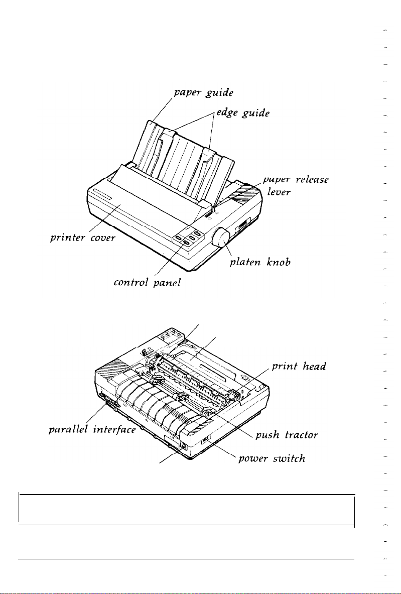
Names of the Parts
paper tension unit cover
ribbon cartridge
AC inlet
Note: In some locations, the power cord is attached to the
printer.
4
Introduction
Page 14

Chapter 1
Setting Up the Printer
Unpacking the
Choosing
Assembling
Installing
Installing
Attaching
Testing
Plugging
Running the
Connecting
The
Setting
Choosing
Place
a
the Printer..
the
the
the paper
Printer..................................................................
the
in
the PrintertoYour Computer..
parallel
Up
Your
fromamenu..
Printer . . . . . . . . . . . . . . . . . . . . . . . . . . . . . . . . . . . . . . . . . . . . . . . . . . . . . . . . . . . .
for the
platen
ribbon cartridge
the
printer..
self test..
interface.. ........................................................
Application
Printer . . . . . . . . . . . . . . . . . . . . . . . . . . . . . . . . . . . . . . . . . . .
.........................................................
knob..
guide
................................................
...........................................
.................................................
.....................................................
........................................................
........................
Software ................................
.....................................................
1-2
1-3
1-5
1-5
1-6
1-9
1-10
1-10
1-10
1-13
1-13
1-14
1-14
Setting Up the Printer
l-l
Page 15
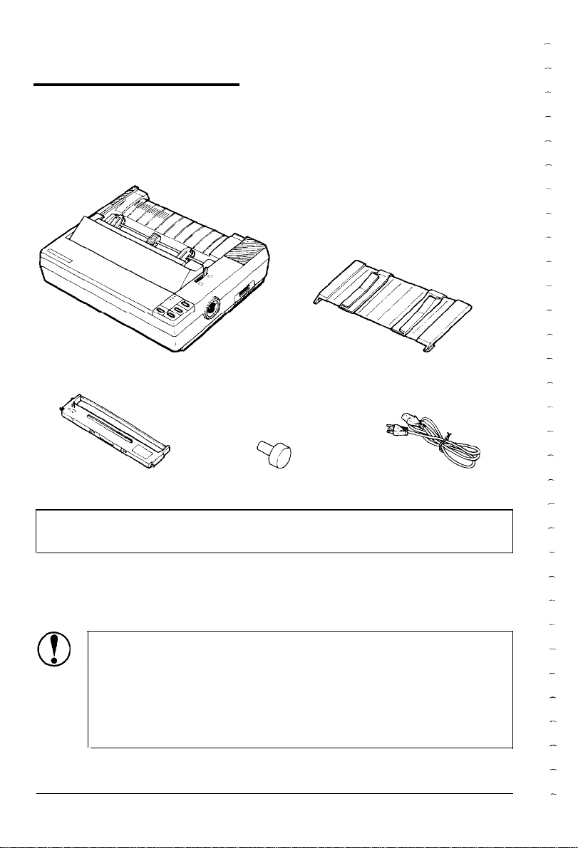
Unpacking the Printer
When you unpack the printer, make sure that you have all the
parts shown below and that none has been damaged.
printer
ribbon cartridge
platen knob
paper guide
power cable
Note: In some locations, the power cord is attached to the
printer.
After removing the parts, save the packaging materials in case you
ever need to transport your printer.
CAUTION: There are several different versions of the
printer designed for different electrical standards. It is not
possible to adjust the printer for use at another voltage.
The power supply type is shown on the label on the
back of the printer. If it does not show the correct
voltage for your country, contact your dealer.
1-2
Setting Up the Printer
Page 16
Choosing a Place for the Printer
When selecting a place to set up your printer, be sure to keep the
following in mind:
l
Place the printer on a flat, stable surface.
Place the printer close enough to the computer for the printer
cable to reach.
l Leave adequate room around the printer to allow for easy
operation and maintenance.
CAUTION: Avoid locations that are subject to direct
sunlight, excessive heat, moisture, or dust.
Use a grounded outlet; do not use an adapter plug.
Avoid electrical outlets controlled by wall switches or
automatic timers. Accidental interruption of power can wipe
out information in the memory of your computer or your
printer.
Avoid outlets on the same circuit with large motors or other
appliances that might cause fluctuations in line voltage.
Keep the entire computer system away from potential sources
of electromagnetic interference such as loudspeakers or the base
units of cordless telephones.
Setting Up the Printer
1-3
Page 17

Choosing a Place for the Printer
Note: If you plan to use a printer stand, follow these guidelines:
Use a stand that supports at least 11.6 kg (25½ lbs), which is
twice the weight of the printer.
Never use a stand that tilts the printer at an angle of more
than 15 degrees from horizontal. If you install a cut-sheet
feeder, keep your printer absolutely level.
If you position the paper supply below the printer stand, make
sure that you allow enough clearance (25 mm or 1 inch) to
keep the paper from catching on the underside of the stand.
Also see that the distance between the stand’s supports is at
least
280
mm
(11
inches), to accommodate any paper size you
may use.
Position your printer’s power cord and interface cable so that
they do not interfere with paper feeding. If possible, secure the
cables to the printer stand.
l-4
Setting Up the Printer
Page 18
Assembling the Printer
After choosing a good place for your printer, the next step is to
install the platen knob.
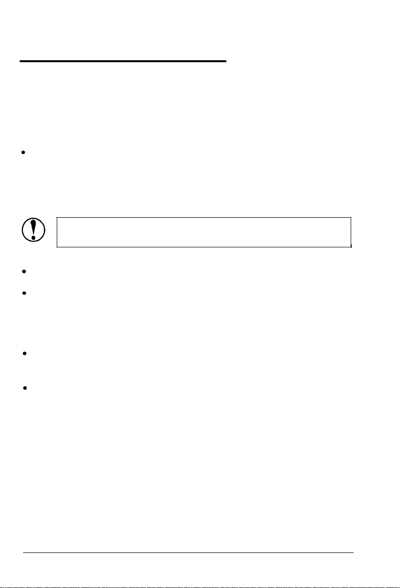
Installing the platen knob
You use the platen knob to manually feed paper in the printer
when the printer is turned off. You will find the platen knob
packed in an indentation in the white foam packaging material.
1.
Insert the knob into the hole on the printer’s side and rotate it
slowly until it slips onto the shaft.
2.
Push firmly on the platen knob until it fits against the printer
case.
Setting Up the Printer
l-5
Page 19
Assembling the Printer
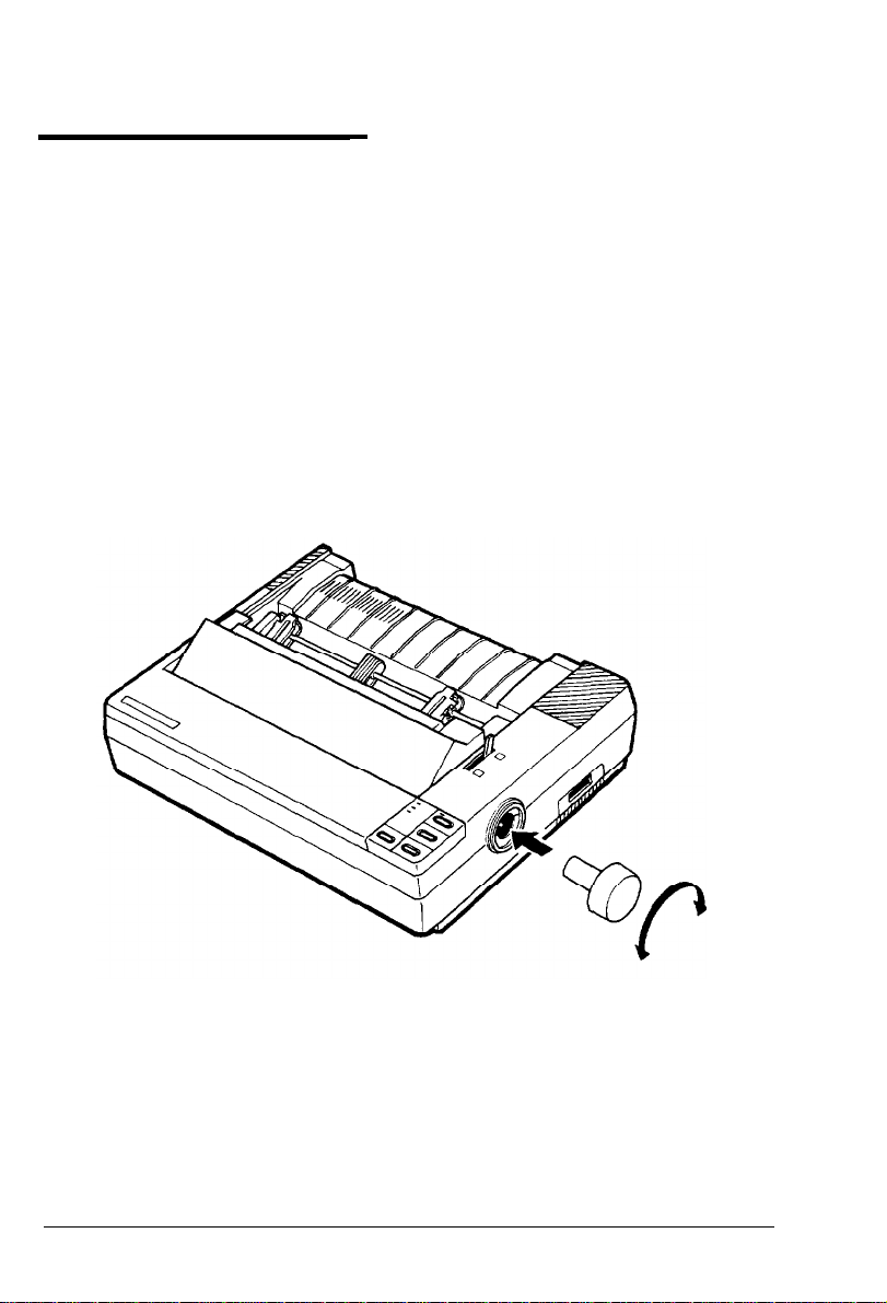
Installing the ribbon cartridge
Before installing the ribbon cartridge, make sure that the printer is
not plugged into an electrical outlet.
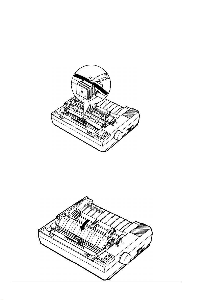
1.
Raise the printer cover to the upright position. Then lift the
cover up and off.
2.
Slide the print head to the middle of the printer. Then open
the paper tension unit cover.
1-6
Setting Up the Printer
Page 20
Assembling the Printer
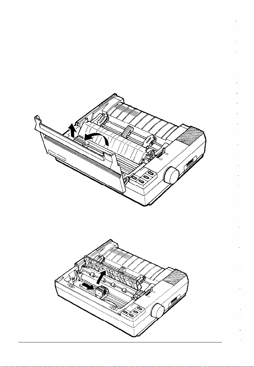
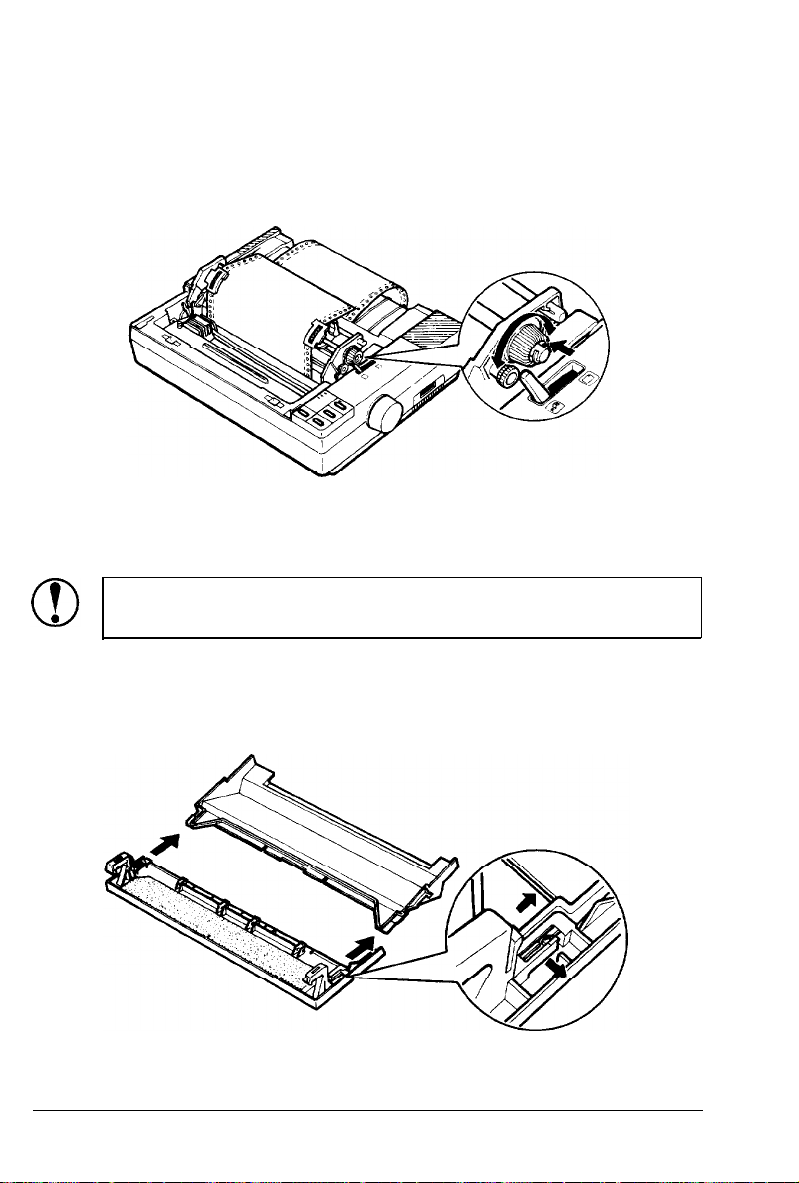
3.
Turn the ribbon-tightening knob in the direction of the arrow.
This removes slack from the ribbon, making it easier to install.
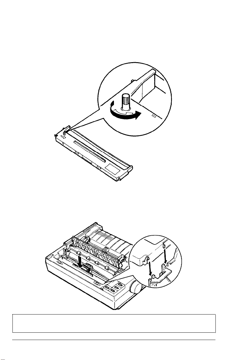
4.
Hold the ribbon cartridge by its handle and push it firmly
down into position, making sure the plastic hooks fit into the
slots.
Note: Press lightly on both ends of the cartridge to make sure
the plastic hooks are properly seated.
Setting Up the Printer
l-7
Page 21
Assembling the Printer
5.
Use a pointed object, such as a ball point pen, to guide the
ribbon between the print head and ribbon guide while you
turn the ribbon-tightening knob to help feed the ribbon into
place.
Slide the print head from side to side to make sure that it
6.
moves smoothly. Also check that the ribbon is not twisted or
creased.
7.
Close the paper tension unit cover.
1-8
Setting Up the Printer
Page 22
Assembling the Printer
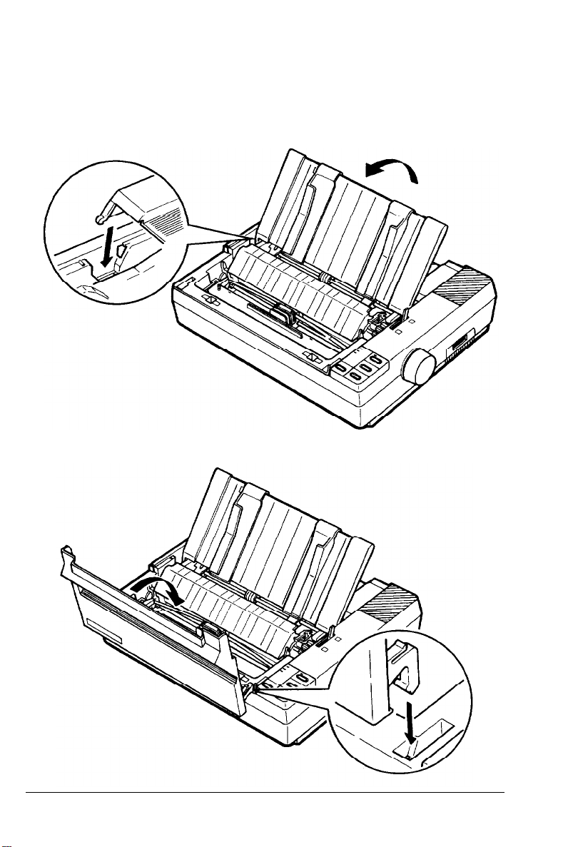
Attaching the paper guide
1.
Place the paper guide on the printer. Then raise it up until it
locks into place.
2. Attach the printer cover.
Setting Up the Printer
1-9
Page 23
Testing the Printer
Before connecting your printer to a computer, use the built-in
self-test function to see that the printer is working properly.
Before running the self test, you need to connect your printer to
an electrical outlet.
Plugging in the printer
1. Make sure that the printer is turned off.
2.
Check the label on the back of the printer to make sure the
power rating required by the printer matches that of your
electrical outlet.
CAUTION: If the rated voltage and your outlet voltage
do not match, contact your dealer for assistance. Do not
plug in the power cord.
3.
If necessary, connect the power cord to the AC inlet on the
printer’s back panel.
4.
Plug the power cord into a properly grounded electrical outlet.
Running the self test
The self test runs in draft or Near Letter Quality (NLQ) mode,
depending on which button you hold down as you turn on the
printer.
1.
Make sure that the printer is turned off and then push the
paper release lever back to the single-sheet position.
2.
While holding down the LINE FEED button (draft mode) or FORM
FEED button (NLQ mode), turn on the printer. The POWER and
PAPER OUT lights come on.
1-10
Setting Up the Printer
Page 24
Testing the Printer
3.
Slide the left edge guide until it locks in place at the guide
mark. Next, adjust the right edge guide to match the width of
your paper.
4.
Slide a sheet of paper down firmly between the edge guides
until it
meets resistance.
CAUTION: Run the self test using paper wider than A4
(210 mm or 8½ inches) or letter size (216 mm or 8½
inches), to prevent the print head from printing directly
on the platen.
Setting Up the Printer
l-11
Page 25
Testing the Printer
5. Press the LOAD/EJECT button to load paper.
6. Press the ON LINE button to start the self test. The test prints
list of DIP switch settings first, followed by a series of
characters.
7.
The self test continues until the paper runs out or you press
the ON LINE button. When you wish to stop the test, press the
ON LINE button.
Note: To resume the test, press the ON LINE button again.
8.
To end the self test, be sure the printer is not printing. Press
the LOAD/EJECT or LINE FEED button to eject the paper. Then
turn off the printer.
CAUTION: After turning the power off, always wait at
least five seconds before turning it back on. Turning the
power on and off rapidly can damage the printer.
Here is part of a typical self test printed in Near Letter Quality
mode.
!"#$%&`()*+,-
!"#$%&`()*+,
./0123456789:;<=>?@ABCDEFGHIJK
-./0123456789:;<=>?8ABCDEFGHIJKL
“#$%&‘()*+,-./0123456789:;<=>?@ABCDEFGHIJKLM
#$%&`()*+,-
$%&‘()*+,-
./0123456789:;<=>?@ABCDEFGHIJKLMN
./0123456789
:;<=>?@ABCDEFGHIJKLMNO
%&‘()*+,- ./0123456789:;<=>?@ABCDEFGHIJKLMNOP
&‘()*+,-./0123456789:;<=>?@ABCDEFGHIJKLMNOPQ
‘()*+,-
./0123456789:;<=>?@ABCDEFGHIJKLMNOPQR
)*+,-./0123456789:;<=>?@ABCDEFGHIJKLMNOPQRS
)*+,-./0123456789:;<=>?@ABCDEFGHIJKLMNOPQRST
*+,-
./0123456789:;<=>?@ABCDEFGHIJKLMNOPQRSTU
Note: If the test did not print satisfactorily, see Chapter 6.
1-12
Setting Up the Printer
Page 26
Connecting the Printer to Your Computer
If the self test printed correctly, you are ready to connect your
printer to the computer. Most computers have a parallel interface.
To connect such an interface, use a suitable shielded cable as
described in the next section.
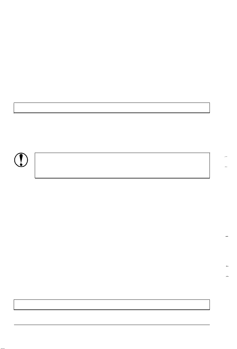
The parallel interface
Connect the parallel interface cable as described below:
1.
Make sure that both your printer and computer are turned off.
Plug the cable connector securely into the printer. Then
squeeze the wire clips together until they lock in place on
either side of the connector.
Note: If your cable has a ground wire, connect it to the ground
connector beneath the interface connector.
2.
Plug the other end of the cable into the computer. (If there is a
ground wire at the computer end of the cable, attach it to the
ground connector at the back of the computer.)
Setting Up the Printer
1-13
Page 27

Setting Up Your Application Software
Most application programs let you specify the type of printer you
are using so that the program can take full advantage of the
printer’s features. Many of these programs provide an installation
or setup section that presents a list of printers.
Choosing from a menu
Because the family of Epson printers shares a great many
commands, you can use an application program even if it does not
list your printer on its printer selection menu. If your printer is not
listed, choose from the following list. (The printers are listed in the
order of preference.)
LX-810/850
LX-800
LX-86
LX-80
FX-850
FX-86e
EX-800
FX-85
FX-80+
FX-80
If none of these printers is listed, select the first one available on
the following list: LX, FX, EX, RX, MX, Epson printer, Standard
printer, Draft printer.
To use all of the features of the printer, however, it is best to
choose a program with one of the LX printers on its menu. If your
program does not list one of these printers, contact the software
manufacturer to see if an update is available.
1-14
Setting Up the Printer
Page 28

Chapter 2
Paper Handling
Using Single Sheets
Loading
Printing
Using
the
multiple-page
Continuous Paper
Positioning your continuous
Loading
Adjusting
continuous paper..
the
Loading
................................................................
paper
...............................................................
documents..
..................................
........................................................
paper
supply......................
................................................
Position
. . . . . . . . . . . . . . . . . . . . . . . . . . . . . . . . . . . . . . . . . . . .
Switching Between Continuous and Single Sheets..
Switching
Switching
to single sheets..
backtocontinuous
Printing on Special Paper
The paper-thickness lever
Multi-part forms
Labels
Envelope
....................................................................................
...............................................................................
.................................................................
................................................
paper
................................
.......................................................
..................................................
2-2
2-2
2-3
2-4
2-4
2-4
2-7
.......... 2-8
2-8
2-9
2-10
2-10
2-11
2-11
2-12
Paper Handling 2-l
Page 29
Using Single Sheets
Your printer can .accommodate single sheets with a width of 182
mm
(7.2
inches) to
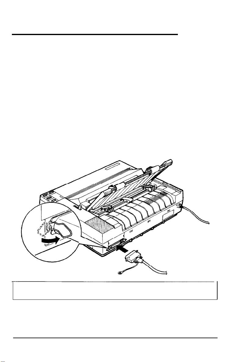
Loading the paper
Turn off the printer; then place the paper guide in the upright
1.
position. Set the paper release lever to the single-sheet position.
Turn on the printer. The POWER and PAPER OUT lights come on.
2.
257
mm
(10.1
inches).
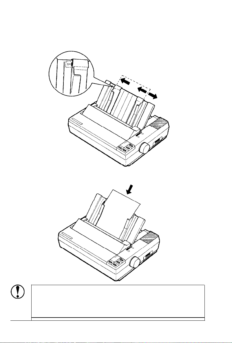
Slide the left edge guide until it locks in place at the guide
3.
mark. Next, adjust the right edge guide to match the paper
width.
2-2
Paper Handling
Page 30

Using
Single
4.
Slide the paper down between the edge guides until it meets
Sheets
resistance.
5.
Press the LOAD/EJECT button once to load the paper.
Note: If the platen turns without loading the paper, remove the
paper and re-insert it more firmly. Then press the LOAD/EJECT
button again.
CAUTION: Never advance the paper using the platen
knob while the minter is turned on.
6.
Press the ON LINE button to set the printer on line.
To eject the paper, set the printer off line (by pressing the ON LINE
button) and then press the FORM FEED button.
Printing multiple-page documents
When you print a document of more than one page using singlesheet paper, you must reload paper at the end of each page. To
reload, first see that the printer is off line. (If the ON LINE light is
on, press the ON LINE button once to take the printer off line.)
Then load a new sheet by following steps 4, 5, and 6 above.
If your software has not been set up properly, the printer may
print too low on the second page of a document or print the last
few lines of one page on the next. If this happens, see Tips for
printing on single sheets at the beginning of this manual for
instructions on how to correct the problem.
Paper Handling 2-3
Page 31
Using Continuous Paper
The push tractor built into your printer can handle paper widths
from
101
mm
(4.0
inches) to
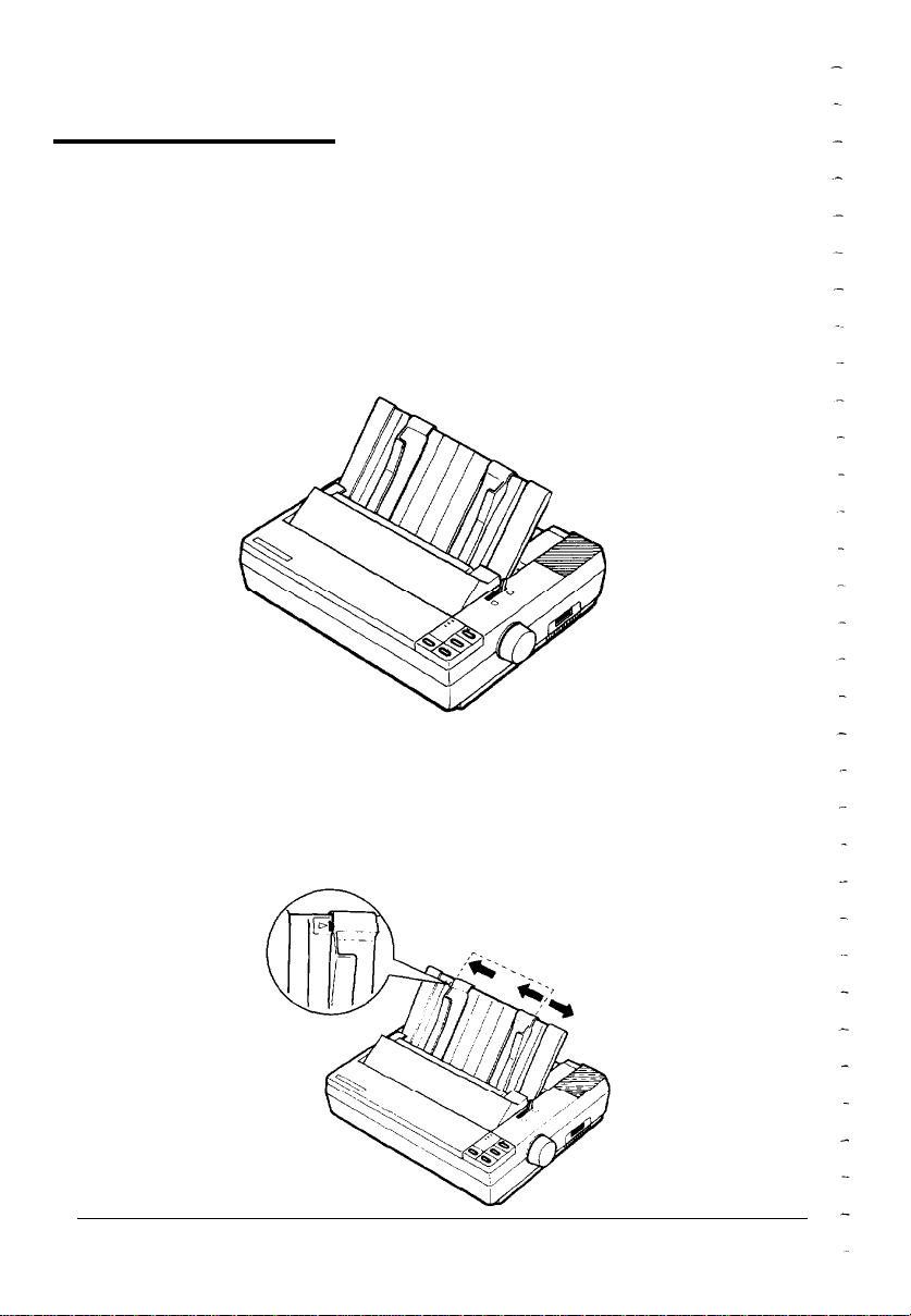
Positioning your continuous paper supply
Here are three ways to position your printer and supply of
continuous paper.
Make sure you align your paper supply with the paper loaded in
the tractor so that the paper feeds smoothly into the printer.
Loading continuous paper
1.
Make sure the printer is turned off. Then remove the paper
guide and pull the paper-release lever forward to the
continuous paper position.
254
mm
(10.0
inches).
2. Release the sprocket units by pulling the sprocket locks
forward.
2-4
Paper Handling
Page 32

Using Continuous Paper
3. Slide the left sprocket unit to approximately 12 mm (l/2 inch)
from the far left position and push the lever back to lock it in
place. Then slide the right sprocket unit to match the width of
your paper, but do not lock it.
4.
Move the paper support midway between the two sprocket
units.
5.
Open both sprocket covers. Fit the first three holes in the
paper over the pins of both sprockets.
CAUTION: Make sure that your paper has a clean,
straight edge before inserting it into the printer.
Paper Handling 2-5
Page 33

Using Continuous Paper
6. Close the sprocket covers.
Slide the right sprocket unit to a position where the paper is
7.
straight and not wrinkled; then lock it in place.
8.
To separate the incoming paper from the outgoing printed
paper, attach the paper guide in its flat position over the
printer and incoming paper. Then slide the edge guides to the
center of the paper’s width.
9.
Turn on the printer. The POWER and PAPER OUT lights come on.
10.
11. Press the ON LINE button to set the printer on line.
The printer remembers the loading position and advances each
page to the same position. If you need to adjust the loading
position, use the micro-adjustment feature. See the section on
adjusting the loading position in Chapter 3.
Press
position.
the LOAD/EJECT
button to feed paper to the loading
CAUTION: Use the platen knob only when the printer is
off and there is a paper-feeding problem, such as a paper
jam. Otherwise you may damage the printer or cause it
to lose track of the loading position.
Note: Before you begin printing, be sure to check the page
length and skip-over-perforation settings, and readjust the
settings if necessary. See the sections on page length and skipover-perforation in Chapter 3.
2-6 Paper Handling
Page 34

Adjusting the Loading Position
The loading position is the point where the paper stops when you
load paper using the LOAD/EJECT button. This position is important
because it determines where the printing begins on the page. If the
printing is too high or too low on the page, change the loading
position using the micro-adjustment feature as described below.
l
1.
2.
3.
after turning on the printer. (If you need to use the
platen knob, first turn off the power.) When you need to
adjust the loading position, always use the following
procedure.
Make sure that the printer is turned on and that paper (single
sheet or continuous) is ready for loading.
Press the LOAD/EJECT button to feed paper to the loading
position. Then press and hold down the ON LINE button until
the beeper sounds once and the ON LINE light begins to blink.
Press the FORM FEED button to feed the paper forward or the
LINE FEED button to feed the paper backward. When you have
set the desired loading position, you can begin printing; the ON
LINE light automatically stops blinking.
Note: You can use the FORM FEED and LINE FEED buttons to
adjust the loading position only while the ON LINE light is
blinking.
CAUTION: Never use the platen knob to feed paper
Paper Handling 2-7
Page 35

Switching between Continuous and Single Sheets
While using continuous paper, you can easily switch to singlesheet printing without removing the continuous paper from the
tractor.
Switching to single sheets
1.
If the printer is on line, press the ON LINE button to set the
printer off line.
2. Tear off all outgoing sheets of continuous paper.
3.
Press the LOAD/EJECT button to feed the continuous paper
backward out of the printer and into the standby position.
l
4.
Push the paper-release lever back to the single-sheet position.
5.
Stand the paper guide upright and move the left edge guide so
that it locks in place next to the guide mark.
6.
Adjust the right edge guide to match the width of the paper.
Then, slide the paper down between the edge guides until it
meets resistance.
7.
Press the LOAD/EJECT button to automatically feed the single-
sheet paper to the loading position. Then, press the ON LINE
button to set the printer on line.
If you are using narrow paper (less than
l
152.4
6 inches wide), you should only press the LOAD/EJECT
button once. Also, do not use this button to eject
labels.
Never feed labels backward through the printer.
l
Labels can easily come off the backing sheet and jam
the printer.
CAUTION:
mm or
2-8
Paper Handling
Page 36

Switching Between Continuous and Single Sheets
Switching back to continuous paper
1.
Make sure that the single sheet is ejected and the printer is off
line.
2.
Slide the edge guides together so that they meet at the center
of the paper’s width.
3.
Lower the paper guide onto the back of the printer.
4.
Pull the paper release lever forward to the continuous paper
position.
5.
Press the LOAD/EJECT button to feed the continuous paper to
the loading position.
6.
Press the ON LINE button to set the printer on line so it can
accept data.
Paper Handling 2-9
Page 37

Printing on Special Paper
In addition to printing on single sheets and continuous paper, your
printer can also print on a wide variety of paper types, such as
labels and multi-part forms. Before printing on special types of
paper,
you may need to change the paper-thickness setting.
CAUTION:
l When printing on labels or multi-part forms, make
sure that your application program settings keep the
printing entirely within the printable area.
l Always return the paper-thickness lever to position 2
when you go back to printing on ordinary paper.
The paper-thickness lever
For normal use, set the paper thickness lever to position 2.
2-10
Paper Handling
Page 38

Printing on Special Paper
When printing on other types of paper, set the paper thickness
lever according to the table below.
Paper type
Ordinary paper (single sheet or continuous)
Thin paper
24 lb paper (single sheet)
Multi-part forms 2-sheet
3-sheet
Labels
Envelopes
Air mail
Plain
Bond (20 lb)
Bond (24 lb)
Lever position
2
2
3
2
3
4
4 or 5
6
6
7
Multi-part forms
With the pull-tractor installed, your printer can print on
continuous multi-part forms of up to three parts (including the
original). Make sure you set the paper thickness lever to the proper
position using the table above.
Labels
When printing labels, always choose the type mounted on a
continuous backing sheet with sprocket holes for use with a
tractor.
CAUTION:
l Never feed labels backward through the printer.
Labels can easily peel off the backing and jam the
printer.
l Since labels are especially sensitive to temperature
and humidity, use them only under normal operating
conditions.
l Do not leave labels loaded in the printer between
jobs; they curl around the platen and may jam when
you resume printing.
Paper Handling
2-11
Page 39

Printing on Special Paper
EnvelopeEnvelope
You can load envelopes just like single-sheet paper. However, youYou can load envelopes just like single-sheet paper. However, you
should pay attention to the special considerations below:should pay attention to the special considerations below:
CAUTION: Only use envelopes under normal operatingCAUTION: Only use envelopes under normal operating
condition.condition.
Note:
l Always set the paper-thickness lever to the position
indicated for envelopes in the paper-thickness lever section
in this chapter.
l Always feed envelopes by inserting the wide edge into the
printer.
l Make sure your application software keeps the printing
within the printable area of the envelopes you are using.
2-12
Paper Handling
Page 40

Chapter 3
Using the Printer
Operating the Control Panel
Lights
Buttons
SelecType
....................................................................................
..................................................................................
.............................................................................
Other control panel features
Setting the DIP Switches
Changing a DIP switch setting
..................................................
.............................................
.......................................................
.........................................
DIP-switch settings.............................................................
DIP-switch functions
Selecting Typestyles
Character fonts
....................................................................
Condensed mode
Selecting
International Character
an
Choosing a Character Table
..........................................................
...............................................................
.................................................................
Set . . . . . . . . . . . . . . . . . . . . . . . . . . . . . .
. . . . . . . . . . . . . . . . . . . . . . . . . . . . . . . . . . . . . . . . . . . . . . . . . .
3-2
3-2
3-2
3-3
3-4
3-5
3-5
3-6
3-7
3-9
3-9
3-10
3-11
3-12
Using the Printer
3-l
Page 41

Operating the Control Panel
The indicator lights give you the current status of the printer. The
buttons let you control many of the printer settings.
Lights
POWER
READY
PAPER
OUT
LOAD/EJECT LINE FEED
ON LINE
OFF LINE
POWER
(green)
On when the power switch is on
and power is supplied.
READY
(green)
On when the printer is ready to
accept input data. This light
flickers during printing.
PAPER OUT
(red)
On when the printer is out of
paper or when continuous paper
is in the standby position. The
printer also beeps when it is out
of paper.
ON LINE (green)
On when the printer can receive
and print data from the
computer. When this light is
blinking, you can use the micro-
adjustment feature.
Buttons
3-2
Using the Printer
ON LINE
This button controls the printer’s on line/off line status.
When the printer is on line, the ON LINE light is on and
the printer can receive and print data from the computer.
Page 42

FORM FEED
When the printer is off line, press this button to eject a
single sheet of paper or to advance continuous paper to the
top of the next page.
LINE FEED
When the printer is off line and paper is loaded, press this
button to feed the paper one line, or hold it down to feed
paper continuously.
LOAD/EJECT
Use this button to feed the paper to the loading position or
to eject paper that is already loaded. The printer ejects
paper forward if the paper release lever is set to the singlesheet position; it ejects paper backward (removes it from
the paper path) if the release lever is set to the continuouspaper position.
SelecType
Operating the Control Panel
When the printer is on line, you use the FORM FEED, LINE FEED, and
LOAD/EJECT buttons to select the printer’s built-in character fonts.
NLQ
Press this button to select the NLQ Roman and NLQ Sans
Serif fonts. When you select Roman, the printer beeps
twice. When you select Sans Serif, the printer beeps three
times.
DRAFT
Press this button to select draft printing. When you select
draft printing, the printer beeps once.
Using the Printer
3-3
Page 43

Operating the Control Panel
CONDENSED
Press this button to select or deselect the condensed mode.
The printer beeps once when you select the condensed
mode and beeps twice when you deselect it. In the
condensed mode all characters are approximately 60% of
their normal width.
Note: You cannot select the condensed mode while using the
Roman or Sans Serif NLQ fonts.
Other control panel features
The control panel also gives you access to several special functions.
Self test:
Micro-adjustment:
Data dump:
The self test lets you check that your printer
is operating properly and prints out the
current DIP switch settings. See the section
on testing the printer in Chapter 1 for more
information.
The micro-adjustment function allows you to
make fine adjustments to the loading and
short tear-off positions. See the section on
adjusting the loading position in Chapter 2
and the section on using short tear-off later
in this chapter.
The data dump mode allows advanced users
to find the cause of communication problems
between the printer and application
programs. To use data dump mode, make
sure that paper is loaded and the printer is
off. Then hold down the FORM FEED and LINE
FEED buttons and turn on the printer. Your
printer then prints all codes it receives in
hexadecimal format, as shown below.
3-4
To turn off data dump mode, press the ON LINE button to
take the printer off line; then turn off the printer.
Using the Printer
Page 44

Setting the DIP Switches
By changing the settings of the two sets of DIP switches on the
right side of the printer, you can control various printer features,
such as the character set and page length. These new settings
become effective whenever the printer is turned on, reset, or
initialized.
Changing a DIP switch setting
1. Turn off the printer.
2.
Use a pointed instrument, such as the tip of a pen, to turn a
switch on or off. The tables on the following pages give the
DIP-switch functions for each setting.
The new DIP switch settings take effect when the printer is turned
on.
Using the Printer
3-5
Page 45

Setting the DIP Switches
DIP switch settings
The tables below show the settings for each DIP switch function.
The current settings appear on your self test printout.
DIP Switch 1
characters and See Table 2
D/P Switch 2
SW
Description
ON
OFF
2-1
Short tear-off
2-2
Cut-sheet feeder mode
2-3
Skip-over-perforation
2-4
Auto line feed
Table 1 Page length
Page length
11 inches
12 inches
8.5 inches
11.7 inches
3-6
Using the Printer
SW1-3 SW1-4
I
Invalid Valid
ON OFF
ON OFF
ON OFF
OFF OFF
ON OFF
OFF ON
ON ON
Page 46

Table 2 International character set and PC selection
Setting the DIP Switches
I I
OFF
OFF
OFF
Spain
I
PC 437
DIP switch functions
This section describes the different features you can control with
the printer’s DIP switches.
Character spacing
DIP switch l-l controls the character spacing. If this switch is off,
the printer prints with character spacing of 10 cpi (characters per
inch); if it is on, the printer prints with character spacing of 12 cpi.
This is 10 cpi printing.
ABCDEFGHIJKLabcdefghijkl
This is 12 cpi printing.
ABCDEFGHIJKLabcdefghijkl
Shape of zero
When DIP switch l-2 is on, the printer prints slashed zeros (8);
when off, the printer prints open zeros (0).
Page length
DIP switches l-3 and l-4 control the page length. You can select a
page length of
216 mm (8.5
inches),
279
mm
(11
inches),
296
mm
(11.7 inches), or 305 mm (12 inches).
Using the Printer
3-7
Page 47

Setting
the DIP Switches
Short tear-off
When you are finished printing (when the printer receives a full
page of data or a form feed and then no more data for three
seconds), this feature automatically feeds the perforation of
continuous paper to the tear-off edge of the printer cover so that
you can tear off the last sheet. When you resume printing, the
paper feeds backward to the loading position. To use this feature,
set DIP switch 2-l to off and load continuous paper. Moving the
paper release lever to the single-sheet position disables the short
tear-off function.
Adjusting the short tear-off position
1.
Make sure that the short tear-off feature is turned on and that
the paper is in the short tear-off position.
2.
Press and hold the ON LINE button until the printer beeps
once and the ON LINE light begins blinking.
3.
Press the FORM FEED button to feed the paper forward or the
LINE FEED button to feed it backward.
When you resume printing, the ON LINE light stops blinking and
the printer remembers the new tear-off position even after you
turn off the power.
Skip-over-perforation
If DIP switch 2-3 is on when you are using continuous paper, the
printer leaves a 25.4mm (one-inch) space between the last line on
one page and the first line on the next page so that the printer can
skip over the perforation. Because most application programs take
care of the top and bottom margins do not turn on skip-overperforation unless your program does not provide these margins.
3-8 Using the Printer
Page 48

Selecting Typestyles
You can produce a wide range of typestyles by combining different
character fonts, widths, and other enhancements. You can select
typestyles using the SelecType feature on your control panel, the
DIP switches, or software commands.
Character fonts
The printer has three fonts: draft, NLQ Roman, and NLQ Sans
Serif. The draft font uses fewer dots per character to allow highspeed printing, which makes it ideal for rough drafts and editing
work.
NLQ Roman and NLQ Sans Serif are Near Letter Quality fonts.
Near Letter Quality produces nicely formed characters suitable for
most documentation needs.
To select the draft font, press the DRAFT (LINE FEED) button when
the printer is on line. When you select the draft font, the beeper
sounds once.
To select the NLQ font, press the NLQ (FORM FEED) button when
the printer is on line. When you select the NLQ Roman font, the
printer beeps two times. When you select the NLQ Sans Serif font,
the printer beeps three times.
Using the Printer
3-9
Page 49

Selecting Typestyles
The following samples show the characters for each font.
Draft
!“#$%&‘()*+,- ./0123456789:;<=>?@ABCDEFGHIJK
LMNOPQRSTUVWXYZ[\]^--’
WXYZ{|}~
Epson Sans Serif
!"#$%&'()*+,-./0123456789:;<=>?@ABCDEFGHIJK
LMNOPQRSTUVWXYZ[\]^-’
wxyz{|}~
abcdefghijklmnopqrstuv
abcdefghijklmnopqrstuv
Condensed mode
You can use the condensed mode to change the character size. In
the condensed mode, characters are approximately 60% of the
width of normal characters. You can condense both 10 and 12 cpi
in draft mode but not NLQ.
To select or cancel condensed mode, press the CONDENSED
(LOAD/EJECT) button when the printer is on line. When you select
the condensed mode, the printer beeps once. When you cancel the
condensed mode, the printer beeps twice.
3-10
Using
the
Printer
Page 50
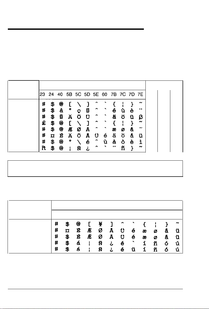
Selecting an International Character Set
International character sets provide you with some characters and
symbols used in other languages. The table below shows the eight
international character sets you can select with DIP switches 1-6,
1-7, and l-8 when DIP switch l-5 is turned off. The table also
shows the characters that differ in each set.
Country
0
U.S.A.
1
France
2
Germany
3
U.K.
4
Denmark
5
Sweden
6
Italy
7
Spain 1
ASCII code hex
1
1-6
ON
ON
ON
ON
OFF
OFF
OFF
OFF
DIP SW
1-7
ON
ON
OFF
OFF
ON
ON
OFF
OFF
Note: If you wish to select an international character set when
DIP switch l-5 is turned on, use the ESC R command.
Besides the eight sets above, the five international character sets
shown below are also available through the ESC R command.
Country
8
Japan
9
Norway
10 Denmark II
11 Spain II
12 Latin America
23 24 40 5B 5C 5D 5E 60 7B 7C 7D 7E
ASCII code hex
l-8
ON
OFF
ON
OFF
ON
OFF
ON
OFF
Using the Printer
3-11
Page 51

Choosing a Character Table
Set DIP switch l-5 on to select the graphics character tables. Set it
off to select the italic character table. The graphics character table
depends on the settings of DIP switches
If you have an IBM® or IBM-compatible computer, select a
graphics character set when you wish to print character graphics as
they are displayed on the screen. Even if you select a graphics
character set, you can still print ordinary text and italics. For
italics, see your software manual or the description of the ESC 4
command in the Command Summary, Chapter 8.
You can also select the italics character set or a graphics character
set using the ESC t command. See the Command Summary in
Chapter
8.
Graphics character sets
1-6, l-7,
and 1-8.
Graphics character set
PC 437 (United States)
PC 850 (Multilingual)
PC 860 (Portugal)
PC 863 (Canada-French)
PC 865 (Norway)
Settings not shown above select PC 437 (United States)
SW1-6 SW1-7 SW1-8 SW1-5
ON
ON ON
ON
ON
OFF ON
ON
OFF ON
OFF
ON
OFF ON
OFF ON
ON ON
ON
ON
The characters in each character set are shown in the Appendix.
Note:
l To change the setting of a DIP switch, first turn off the
printer. Then change the DIP switch and turn the printer
back on.
l Use of the ESC 6 or ESC 7 commands lets you select
whether to print hex codes 90 to 9E and FF as characters
(ESC
6)
or control codes (ESC 7).
3-12
Using the Printer
Page 52

Chapter 4
Using the Printer Options
Cut-Sheet
Installing
Paper
Feeder
the
handling
....................................................................
cut-sheet feeder..
.........................................
....................................................................
Switching between the cut-sheet feeder
push
and
Single
Removing
Tractor..
Pull
Installing
Paper
Removing
Paper Holder
Roll
Installing
Paper
Removing
Interface
Installing
tractor..................................................................
sheet insertion..
the
cut sheet feeder..
........................................................
........................................
............................................................................
the pull tractor
handling
....................................................................
the pull
tractor..
...................................................
................................................
...................................................................
the roll paper holder..
handling
Boards
an
....................................................................
the
roll paper
. . . . . . . . . . . . . . . . . . . . . . . . . . . . . . . . . . . . . . . . . . . . . . . . . . . . . . . . . . . . . . . . . . . . . .
interface
board . . . . . . . . . . . . . . . . . . . . . . . . . . . . . . . . . . . . . . . . . . . . . .
holder..
........................................
......................................
4-2
4-2
4-4
4-6
4-7
4-8
4-9
4-9
4-10
4-12
4-14
4-14
4-15
4-16
4-17
4-17
Using the Printer Options
4-l
Page 53

Cut-Sheet Feeder
The optional cut-sheet feeder (C806121) makes it possible to handle
single-sheet paper more easily and more efficiently. It feeds up to 150
sheets of standard bond paper into the printer automatically.
Installing the cut-sheet feeder
1.
Make sure that the printer is turned off. Remove the paper guide
and printer cover. If the pull tractor is installed, remove it.
2. Separate the two halves of the printer cover by pressing on the
tabs and pulling off the clear plastic half of the printer cover.
3.
Attach the cut-sheet feeder cover to the front half of the
printer cover.
--
4-2
Using the Printer Options
Page 54

Cut-Sheet Feeder
4.
Push the paper release lever to the single-sheet position.
5.
Hold the assembled cut-sheet feeder in both hands and fit its
notches over the pins of the printer.
6. Attach the cut-sheet feeder cover to the printer.
7.
Turn on the cut sheet feeder mode by setting DIP switch 2-2
to on.
8. Turn on the printer.
Using the Printer Options
4-3
Page 55
Cut-Sheet Feeder
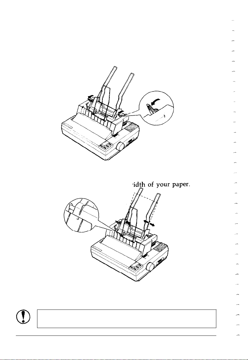
Paper handling
1.
Pull the left and right rear tabs on the cut-sheet feeder forward
until the paper guides retract and lock open to allow for paper
loading.
2.
Slide the left paper guide to where the fin on the edge guide
aligns with the arrow on the front panel. Next, slide the right
paper guide to roughly match the w
3.
Take a stack of paper and fan it. Tap the side and bottom of
the paper on a flat surface to even up the stack.
CAUTION: Do not use multi-part forms, carbon paper,
or labels in the cut-sheet feeder.
4-4
Using the Printer Options
Page 56

Cut-Sheet Feeder
4.
Insert the paper along the left paper guide. Then adjust the
right paper guide to match the paper width. Make sure that the
paper can move freely up and down.
5.
Push the rear tabs on both paper guides backward to clamp the
paper against the guide rollers.
A new sheet of paper loads automatically whenever a printable
character or line feed command is sent to the printer while the ON
LINE light is on.
Note: Run the self test in the cut-sheet feeder mode. The
printer counts the number of lines on the page in l/6-inch line
spacing and prints out this number at the bottom of the first
test page. Use this number to set the lines-per-page with your
software.
Using the Printer Options
4-5
Page 57

Cut-Sheet Feeder
Switching between the cut-sheet feeder and push tractor
You can easily switch between continuous paper and cut-sheet
feeder operation without removing the continuous paper.
Switching to continuous paper
If any single sheets are in the printer, press the ON LINE button
1.
to set the printer off line, then press the LOAD/EJECT button to
eject.
2. Place the paper-release lever in the continuous paper position.
CAUTION: To prevent paper feeding problem, when
printing multiple pages, fold the first printed page
forward after the perforation passes the printer cover
edge.
Switching to the cut-sheet feeder
If any printed sheets remain in the printer, press the ON LINE
1.
button to set the printer off line, then press the FORM FEED
button to advance any printed continuous paper.
2. Tear off the printed pages.
3. Press the LOAD/EJECT button. The printer feeds the
continuous paper backward to the standby position. The paper
is still attached to the push tractor but is no longer in the
paper path.
CAUTION: Never feed labels backward. Labels can
easily come off their backing and jam the printer.
4. Place the paper-release lever in the single-sheet position.
4-6
Using the Printer Options
Page 58
Cut-Sheet Feeder
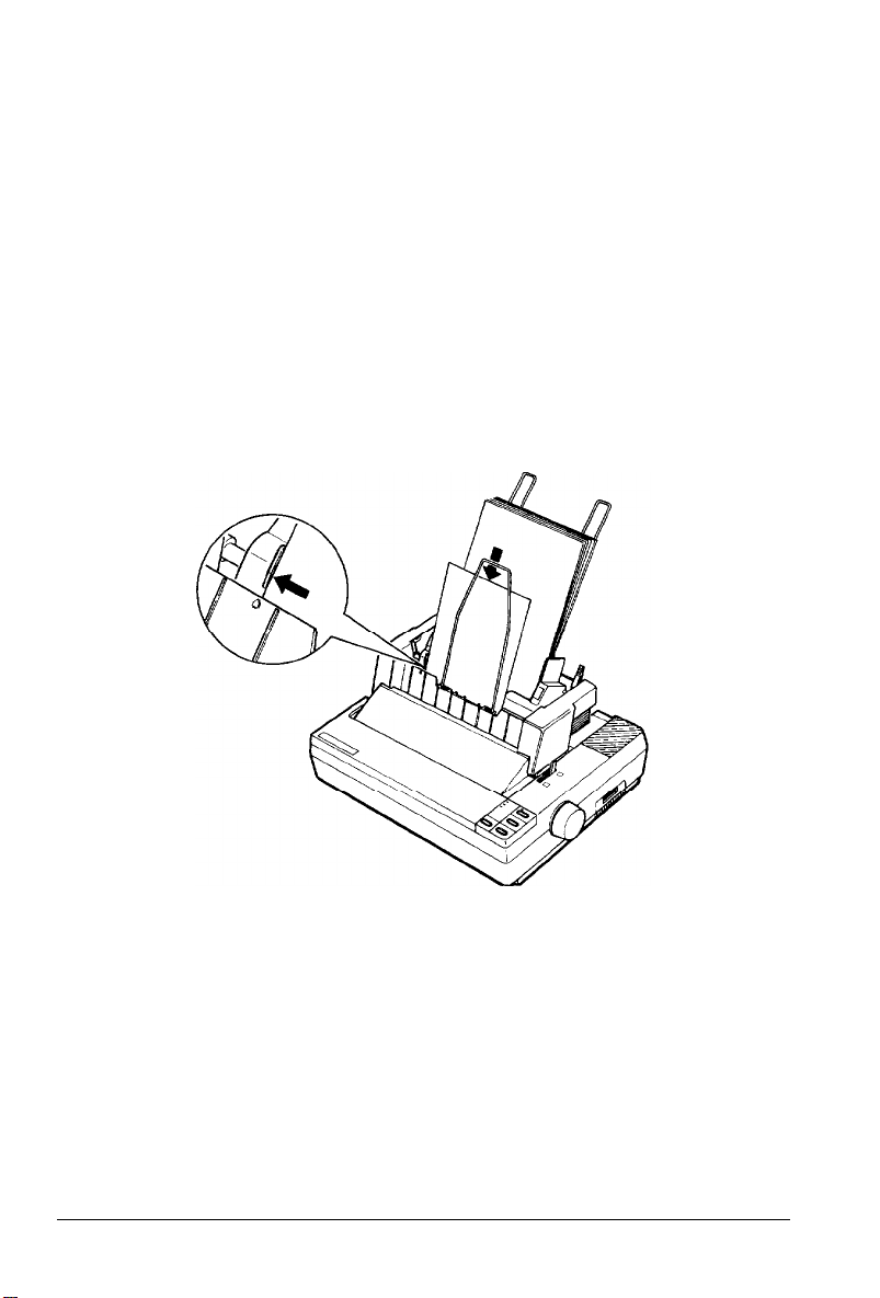
Single sheet insertion
Your cut-sheet feeder also has a single sheet loading feature. This
feature is especially useful because it allows you to switch to a
different type or size of paper (for one sheet only) without
replacing the stack of paper in your cut-sheet feeder.
1.
Press the ON LINE button to set the printer off line.
2.
Align the single sheet to be fed with the mark on the left
paper guide, then slide the sheet into the printer path until you
feel resistance.
3. Press the LOAD/EJECT button to load the sheet.
Using the Printer Options
4-7
Page 59
Cut-Sheet Feeder
Removing the cut-sheet feeder
1.
Turn off the printer. If any paper remains in the bin, remove it.
2. Remove the cut-sheet feeder cover.
3.
Tilt the front part of the cut-sheet feeder backward to release
its notches from the pins in the printer and remove the cutsheet feeder.
4.
Separate the cut-sheet feeder cover from the printer cover and
replace the back half of the printer cover.
5. Install the paper guide and printer cover.
6.
Turn off the cut-sheet feeder mode by setting DIP switch 2-2
to off.
Be sure to store the removed cut sheet feeder in its original box
and packing materials.
4-8
Using the Printer Options
Page 60

Pull Tractor
The optional pull tractor (C800061) provides optimum continuous
paper handling and is especially useful with continuous multi-part
forms and labels. For best results, use the pull tractor along with
the built-in push tractor as described in this section. Do not use
short tear-off with the pull tractor.
Installing the pull tractor
1.
Turn off the printer. Then remove the printer cover and paper
guide.
2. Remove the paper tension unit cover.
3.
Fit the tractor unit’s rear notches over the rear mounting pins
of the printer. Then tilt the tractor unit forward until its front
latches lock onto the printer’s front mounting pins.
Using the Printer Options
4-9
Page 61

Pull Tractor
Paper handling
1.
Pull the paper release lever to the continuous paper position;
then turn on the printer.
2.
Position the push tractor’s left sprocket unit about 6 mm (l/4
inch) from the far left position and lock it into place. Then
load continuous paper onto the push tractor as described in
Chapter 2.
3. Press the LOAD/EJECT button to load the continuous paper.
Then press the FORM FEED button to advance the paper one
page for fitting onto the pull tractor.
l
4.
5.
6.
the printer loses track of the top-of-form position. Be
sure to press the LINE FEED or FORM FEED button to feed
paper.
Open the pull tractor sprocket covers and release the sprocket
units by pulling the sprocket locks forward.
Adjust the sprocket units to match the width of the paper;
then position the paper support midway between the two
sprocket units.
Fit the holes of the paper over the tractor pins of the sprocket
units, and then close the sprocket covers.
CAUTION: If you use the platen knob to feed the paper,
4-10
Using the Printer Options
Page 62
Pull Tractor
7.
If the paper does not fit exactly onto the tractor pins, press on
the pull tractor knob and turn it in the desired direction until
the paper fits properly.
8.
Make sure that the paper-release lever is set forward to the
continuous paper position.
CAUTION: Make sure that the pull tractor’s sprocket
units are aligned with those of the built-in push tractor.
9.
Separate the two halves of the printer cover by pressing on the
tabs and pulling off the clear plastic half.
Using the Printer Options
4-11
Page 63

Pull Tractor
10. Attach the tractor cover to the front half of the printer cover.
11. Install the paper guide; then slide the edge guides together so
that they meet at about the center of the paper’s width.
12. Install the pull tractor cover and press the ON LINE button to set
the printer on line.
While the pull tractor can be used in combination with the built-in
push tractor as described above, the pull tractor can also be used
by itself. Instead of setting the paper on the pins of the push
tractor, simply insert it through the same paper path as you would
use with single-sheet paper.
Removing the pull tractor
1.
If you have a printed document in the printer, set the printer
off line and press the FORM FEED button to feed the paper
forward. Then tear off the document at the perforation.
2.
Press the ON LINE button to set the printer off line. Then press
the LOAD/EJECT button until the continuous paper feeds
backward out of the printer to the standby position. (The
PAPER OUT light comes on.)
CAUTION: Never feed labels backward through the
printer.
4-12 Using the Printer Options
Page 64

Pull Tractor
3.4.Remove the continuous paper from the push tractor unit.
Hold both ends of the tractor unit and slowly tilt the unit back
until the front notches of the unit are free.
Lift the tractor unit up and off.
5.
Reinstall the paper tension unit cover.
6.
7.
Separate the tractor cover from the printer cover and replace
the clear plastic half of the printer cover.
8.
Install the paper guide and printer cover. Push the paper release
lever to the single-sheet position.
Using the Printer Options
4-13
Page 65

Roll Paper Holder
The optional roll paper holder (#8310) allows you to use your
printer with 8.5-inch roll paper like that used with telex machines.
This provides an inexpensive alternative to continuous paper.
Installing the roll paper holder
1.
Turn off the printer and remove the paper guide.
2.
Position the roll paper holder beneath the printer as shown
below. Fit the two holes in the base onto the two positioning
pegs on the bottom of the printer.
3.
Push the paper-release lever to the single-sheet position.
CAUTION: Only the weight of the printer holds the roll
paper holder in place. The positioning pegs only prevent
the printer, be careful to avoid dropping the roll paper
4-14
Using the Printer Options
Page 66

Roll Paper Holder
Paper handling
1.
Turn off the printer. Then push the paper-release lever to the
single-sheet position.
2.
Cut the leading edge of the roll paper straight across.
3.
Slide the roll paper holder shaft through the center of the
paper roll.
4.
Set the shaft and paper roll onto the roll paper holder. Orient
the roll so that paper feeds from the bottom of the roll. Then
turn on the printer.
5.
Bring the leading edge of the paper up over the paper path
guide and insert it into the printer path until you feel
resistance.
6. Press the LOAD/EJECT button to load the paper.
Using the Printer Options
4-15
Page 67

Roll Paper Holder
Install the paper guide; then slide the edge guides together so
7.
that they meet at about the center of the paper’s width. Press
the ON LINE button to set the printer on line.
Note: To tear off paper after printing, set the printer off line,
press the LINE FEED button to advance the paper, then tear off
the paper against the tear-off edge of the printer cover.
Removing the roll paper holder
Cut across the paper behind the point where it feeds into the
1.
printer. Then use the LOAD/EJECT button to eject any paper
remaining in the printer.
2. Turn off the printer.
Remove the paper roll and shaft from the roll-paper holder.
3.
Lift up the printer and separate the roll-paper holder from the
4.
printer.
Be sure to store the roll-paper holder in its original box and
packing materials.
4-16
Using the Printer Options
Page 68

Interface Boards
A number of optional interfaces are available. Serial interfaces are
available if your computer is not equipped with a parallel interface
or if you need an interface that conforms to the Current Loop
standard. An IEEE-488 interface offers standardized connection,
trouble-free operation, and the ability to connect computers,
printers, and other devices on the same line so that they may share
data freely.
Here is a list of Epson interfaces that are compatible with your
printer. Note that some of these interfaces may not be available in
your country or region.
Interface number
#8143
#8148
#8165
To learn more about interfaces, contact your Epson dealer.
New Serial interface
Intelligent serial interface
Intelligent IEEE-488 interface
Name
Installing an interface board
The following sections describe how to install an interface board.
Removing the upper case
CAUTION: Use caution when removing or attaching the
upper case to avoid damaging the printer.
1. Turn off the printer and remove the printer cover and paper
guide.
2. Unplug the power cable from the electrical outlet.
WARNING: High voltages are present inside the printer
when the power is on. Do not remove the upper case
unless the printer is turned off and the power cord is
unplugged. To prevent possible damage by discharge of
static electricity, avoid touching contacts on the circuit
board.
Using the Printer Options
4-17
Page 69

Interface Boards
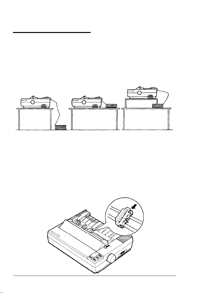
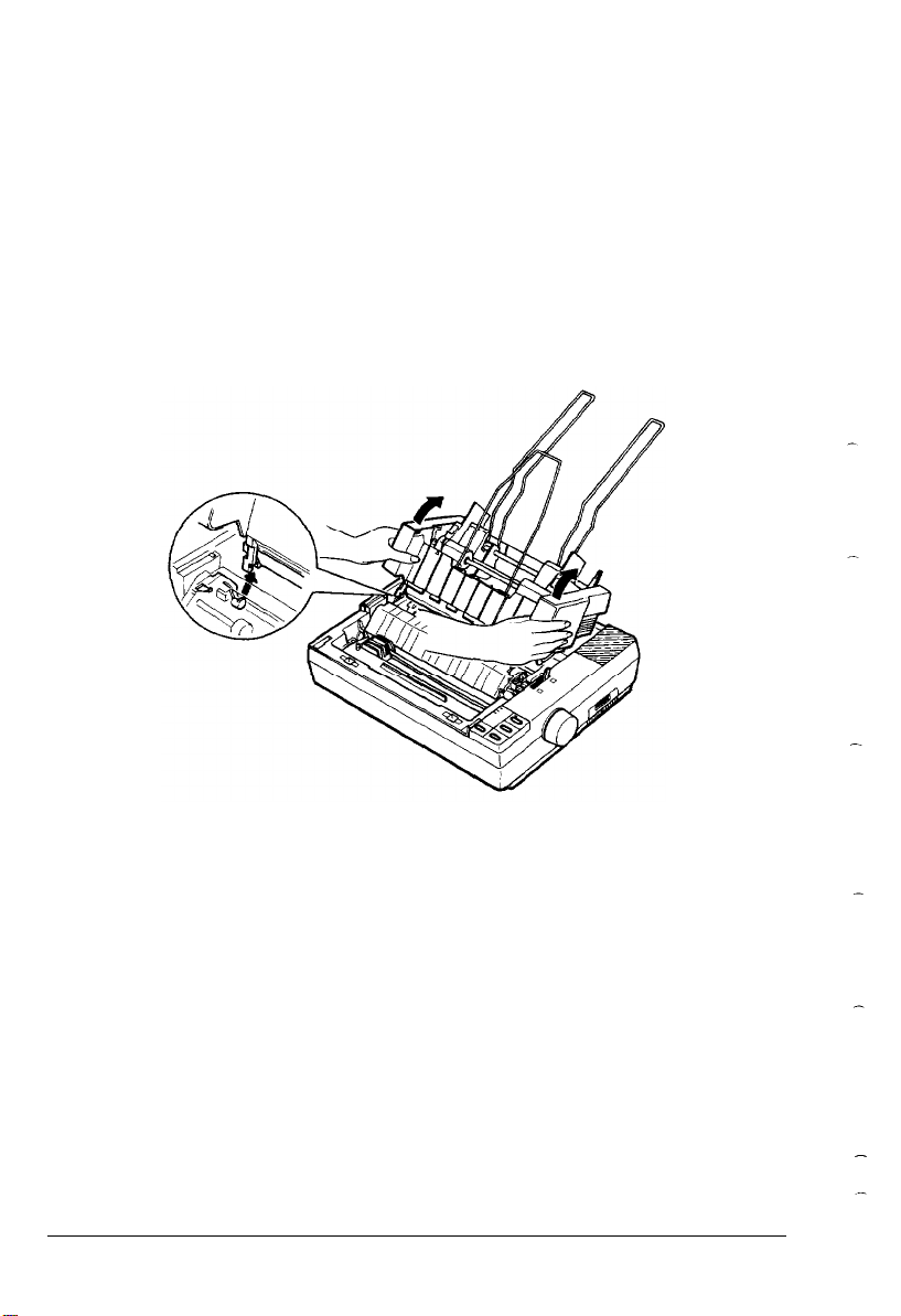
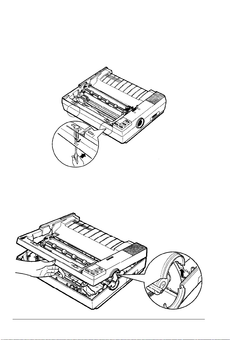
3. Remove the paper tension unit cover, ribbon cartridge, and
platen knob.
Remove the push tractor by pressing the tabs on both sides
4.
using a pointed object.
5. To remove the upper case, first position the printer so that its
front extends slightly over the edge of a table, allowing access
to the openings on the front of the underside of the printer.
CAUTION: Make sure that the printer is not so far
forward that it is in danger of falling off the table.
4-18
Using the Printer Options
Page 70
Interface Boards
6.
Insert a screwdriver into the openings on the underside of the
printer. Gently push the screwdriver up, and press the handle
of the screwdriver toward the back of the printer to release the
clips on the case.
7.
Partially raise the upper case, taking care not to strain the flat
cable attached to the control panel.
8. Carefully disconnect the flat control panel cable from the
connector labelled CN3 on the main board.
Using the Printer Options
4-19
Page 71

Interface Boards
9.
Tilt the upper case backward; then remove it from the printer.
10. Remove the shield plate by pressing in on the plastic clips
located at the back of the plate.
11.
Using a cross-head screwdriver, remove the screw labelled CG
from the main board.
4-20
Using the Printer Options
Page 72

Interface Boards
Installing the board
There are two basic interface board designs, which differ with
respect to how the frame ground (FG) wire is attached. This slight
difference changes the way the boards are installed in the printer,
but does not affect the operation of the interface in any way.
Check below to see which type of interface board you have.
FG wire not attached
1.
Use the CG screw to attach the round end of the FG (frame
FG wire attached
ground) wire to the main board.
Using the Printer Options
4-21
Page 73

Interface Boards
2. Carefully insert the pins on the optional interface board into
the mating connector on the main board; then secure the board
with the three screws provided.
FG wire not attached
If the FG wire is not attached to the interface board, attach the
3.
plug end of the FG wire onto the FG pin located on top of the
interface board.
FG wire attached
4-22
Using the Printer Options
Page 74
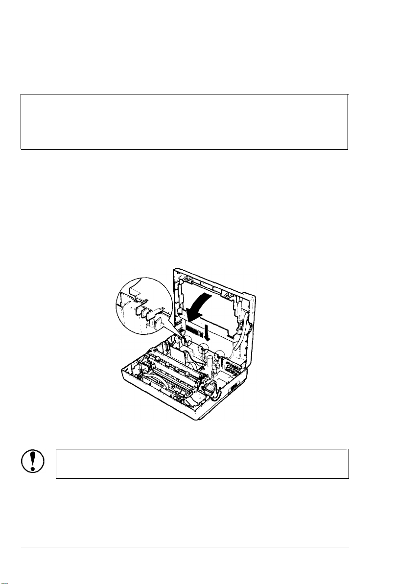
Interface Boards
4. If you have the #8148 or #8165 interface boards, set the
interface DIP switches according to the accompanying manual.
Note: If you have the #8143 interface board, you can select
baud rates from 75 to 9600 BPS (Bits Per Second). (Make sure
you use the bit rate selection table for printers with buffers in
the #8143 interface manual.)
5. Reattach the upper case as described next.
Attaching the upper case
1.
Fit the hinges of the upper case into the openings in the lower
case; then partially lower the upper case.
CAUTION: Take care not to pinch the FG wire between
the upper and lower cases.
Using the Printer Options
4-23
Page 75
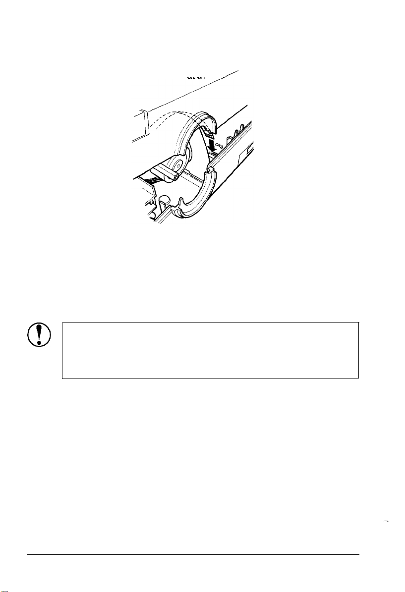
Interface Boards
2. Carefully insert the control panel cable into the connector
labelled CN3 on the main board.
3.
Close the upper case. Press down on the front of the case until
it locks into place.
4. Reattach the push feed tractor.
5. Reattach the ribbon cartridge, paper tension unit cover, and
platen knob.
CAUTION: When you install an optional interface
board, be sure to disconnect the printer cable from the
printer’s built-in parallel interface. You must not connect
two interface cables to the printer at the same time.
4-24 Using the Printer Options
Page 76

Chapter 5
Maintenance
Cleaning the Printer
Replacing the Ribbon
Transporting the Printer
...........................................................................
.........................................................................
....................................................................
5-2
5-3
5-4
Maintenance 5-l
Page 77

Cleaning the Printer
To keep your printer operating at its best, you should clean it
thoroughly several times a year.
1.
Make sure that the printer is turned off. Then remove the
paper guide or, if it is installed, the cut-sheet feeder.
2.
Use a soft brush to carefully clear away all dust and dirt.
3.
If the outer case or paper guide is dirty or dusty, clean it with
a soft, clean cloth dampened with a mild detergent solution.
Keep the printer cover in place to prevent water from getting
inside the printer.
CAUTION:
l
Never use alcohols or thinners to clean the printer,
since these chemicals can damage the components as
well as the case.
l Be careful not to get the printer mechanism or
electronic components wet.
l Do not use a hard or abrasive brush.
l Do not spray the inside of the printer with lubricants;
unsuitable oils can damage the mechanism. Contact
your dealer or a qualified service person if you think
lubrication is needed.
5-2 Maintenance
Page 78

Replacing the Ribbon
When your printing becomes too faint, you need to replace the
ribbon. Use only the Epson #8750 standard ribbon cartridge with
your printer. See Installing the ribbon cartridge in Chapter 1.
WARNING: If the printer has just been used, the
head may be hot. Let it cool before attempting to replace
the ribbon.
Maintenance 5-3
Page 79

Transporting the Printer
If you need to transport your printer some distance, carefully
repack the printer using the original box and packing materials, as
described below.
1.
Turn off the printer.
2.
Remove the paper guide, printer cover, and any installed
options.
3.
Unplug the power cord from the electrical outlet; then
disconnect the interface cable from the printer.
4.
Remove the ribbon cartridge and platen knob.
5.
Reattach the printer cover.
6.
Replace the packing materials and put the printer in its box.
5-4
Maintenance
Page 80

Chapter 6
Troubleshooting
and
Problems
Power
Printing . . . . . . . . . . . . . . . . . . . . . . . . . . . . . . . . . . . . . . . . . . . . . . . . . . . . . . . . . . . . . . . . . . . . . . . . . . . . . . . . . . . . . . . . . . . . . .
Paper
Options . . . . . . . . . . . . . . . . . . . . . . . . . . . . . . . . . . . . . . . . . . . . . . . . . . . . . . . . . . . . . . . . . . . . . . . . . . . . . . . . . . . . . . . . . . . .
Supply . . . . . . . . . . . . . . . . . . . . . . . . . . . . . . . . . . . . . . . . . . . . . . . . . . . . . . . . . . . . . . . . . . . . . . . . . . . . . . .
Handling . . . . . . . . . . . . . . . . . . . . . . . . . . . . . . . . . . . . . . . . . . . . . . . . . . . . . . . . . . . . . . . . . . . . . . . . . .
Solutions
. . . . . . . . . . . . . . . . . . . . . . . . . . . . . . . . . . . . . . . . . . . . . . . . . . . . . . . . . . . . . . . . . . .
6-2
6-3
6-4
6-8
6-10
Troubleshooting 6-l
Page 81

Problems and Solutions
This chapter presents solutions to possible printer problems. If you
have difficulty achieving the desired printing result, first locate the
problem in the listing below and then see the appropriate page for
the solution. If these solutions do not solve your problem, see your
dealer or a qualified service person.
Power supply
See
See
See
See
See
See
See
See
See
See
See
See
See
6-3.
6-4.
6-5.
6-5.
6-S.
6-6.
6-8.
6-9.
6-10
6-11
6-11
6-13
6-15
l Power is not being supplied.
Printing
. The printer does not print.
. The print is faint or uneven.
.
Dots are missing in the printed characters or graphics.
l Printed characters are not what you expected.
l The print position is not what you expected.
Paper handling
l Single sheets do not feed properly.
l Continuous paper does not feed properly.
Options
When you use the cut-sheet feeder, the paper does
not feed properly.
Switching between the cut sheet feeder and the push
tractor does not work properly.
Using the pull tractor with the push tractor,
continuous paper does not feed properly.
With the roll paper holder, paper does not feed
properly.
With an optional interface, the printer does not
operate properly.
6-2
Troubleshooting
Page 82

Power Supply
This section supplies solutions for possible power supply problems.
Power is not being supplied.
l The POWER tight does not go on.
Check that the power cord is properly plugged into the
electrical outlet.
If the electrical outlet is controlled by an outside switch or
automatic timer, use a different outlet.
Plug another electrical device into the outlet to determine
whether the outlet is operating properly.
l The POWER tight comes on briefly and then goes off. The
tight stays off even when the power is turned on again.
Check that the printer’s voltage rating matches the voltage
of your electrical outlet. If the voltages do not match,
unplug the printer and contact your dealer immediately. Do
not reconnect the power cble to an electrical outlet.
Troubleshooting 6-3
Page 83

Printing
This section supplies solutions for possible printing problems.
The printer does not print.
l The ON LINE tight is off.
Press the ON LINE button to put the printer on line.
If the ON LINE light comes on when you remove the printer
cable, either the cable or the interface is bad.
l The ON LINE tight
is on but nothing is printed.
Check that the software is installed properly for your
printer.
Check the software’s printer settings.
Check both ends of the interface cable between the printer
and the computer. Make sure your interface cable meets
both the printer and computer specifications.
l The PAPER OUT tight is on.
Load paper into the printer.
If paper is already loaded, the paper may be set too far to
the right for detection by the paper sensor. Move the paper
a little to the left.
l The printer sounds like it is printing, but nothing is
printed.
The ribbon cartridge may not be installed properly. See the
section on ribbon installation in Chapter 1.
6-4
The ribbon may be worn out. Replace the ribbon cartridge.
Check the paper-thickness setting.
Troubleshooting
Page 84

l The printer makes a strange noise, the buzzer sounds
several times, and the printer stops abruptly.
Turn off the printer and check for paper jams, a jammed
ribbon, or other problems and try to print again. If the
printer still does not print correctly, contact your dealer or a
qualified service person.
The print is faint or uneven.
l Printed characters have parts missing at the bottom.
The ribbon cartridge may not be installed properly. See the
section on ribbon installation in Chapter 1.
l The printout is faint.
The ribbon may be worn out. Replace the ribbon cartridge.
Check that the paper-thickness lever is set correctly for the
paper you are using.
Printing
Dots are missing in the printed characters or graphics.
l A tine of dots is missing in the printout.
The print head is damaged. Stop printing and contact your
dealer or a qualified service person to have the printer
serviced.
l Dots are missing in random positions.
There is either slack in the ribbon or the ribbon has come
loose. Reinstall the ribbon cartridge.
Troubleshooting 6-5
Page 85

Printing
Printed characters are not what you expected.
l The typestyle or characters that are set by your software
cannot be printed.
Check that the software is correctly installed for your
printer.
l The font setected by SelecType does not print.
Your software may be overriding your SelecType setting.
Check the printing style set in your software.
l The wrong characters are printed.
The wrong character table or the wrong international
character set may be selected. Check the DIP switch
settings. See the section on DIP switches in Chapter 3.
Also, you may be using the wrong cable or your cable may
not be properly connected.
The print position is not what you expected.
l Printing starts too high or too tow on the page.
Adjust the top margin set by your application software.
l All the text is printed on the same tine.
Set DIP switch
l Page length does not match the length of the paper.
2-4
off.
Change the page-length setting with DIP switches l-3 and
1-4.
See the section on DIP switches in Chapter
3.
Check the page length set by your application software and
adjust it if necessary.
6-6 Troubleshooting
Page 86

Printing
l Regular gaps occur in the printout.
One-inch skip-over-perforation may be set. Set DIP switch
2-3 off.
Your line-per-page setting in your software may be
incorrect.
l Skip-over-perforation is set, but the perforation does not fall
in the center of the skip.
Adjust the loading position. See the section on DIP
switches in Chapter 3.
Make sure the DIP-switch settings match your required
paper length. See the section on DIP switches in Chapter 3.
If your application program is setting the top and bottom
margins, set DIP switch 2-3 off.
If the printer still does not print correctly, try the self test
described in Chapter 1. If the self test works properly, the printer
is all right, and the problem probably lies in the computer, the
software, or the cable. If the self test does not work, contact your
dealer or a qualified service person.
Troubleshooting 6-7
Page 87

Paper Handling
The following section guides you through problems in handling
single sheets and continuous paper. If you are having problems
using the optional cut-sheet feeder, see the section on options
starting on
Single sheets do not feed properly.
l Printing starts too tow on the page, or the bottom part of
one page is printed at the top of the next page.
l When you press the LOAD/EJECT button, the platen does not
rotate and paper does not feed.
6-10.
Be sure to choose the correct printer when you choose a
printer from your application program’s menu. See Chapter
1.
If possible, specify single-sheet paper with your application
software.
Use your application software to reduce or eliminate the top
margin and reduce the page length.
If the ON LINE light is on, press the ON LINE button once to
set the printer off line.
l When you press the LOAD/EJECT button, the platen rotates
but paper does not feed.
Check that the paper-release lever is pushed back to the
single-sheet position.
6-8
Troubleshooting
Page 88

. The paper feed is crooked or the paper jams.
The cut-sheet feeder mode may be turned on. Set DIP
switch 2-2 off.
Make sure the paper size is within the specified range. See
7-3.
l The paper does not fully eject.
See that the page-length setting is correct.
Continuous paper does not feed properly.
l The paper feed is crooked or the paper jams.
See that the paper-release lever is pulled forward to the
continuous-paper position.
Make sure that the paper supply is not obstructed by a
cable or some other object.
Paper Handling
Make sure that your paper supply is positioned within 1
meter (3 feet) of the printer.
The position of your paper supply may be preventing it
from feeding straight.
See that the holes on the sides of the paper are aligned
with each other. Also, make sure the sprocket units are
locked and their covers are closed.
Check that the paper-thickness lever is set correctly for the
paper you are using.
Check that the paper size is within the specified range. See
7-3.
Troubleshooting 6-9
Page 89

Options
This section describes problems you may encounter while using an
option with your printer.
When you use the cut-sheet feeder, the paper does not feed
properly.
l When a print command is sent from the computer, the
platen rotates but paper does not feed.
Make sure DIP switch l-8 is set on. See the section on DIP
switches in Chapter 3.
The cut-sheet feeder may be incorrectly installed on the
printer.
See that the paper-release lever is pushed back to the
single-sheet position.
You may have loaded too many sheets in the cut-sheet
feeder’s bin.
Paper may be jammed near the print head.
There may be only one sheet left in the bin. Add more
paper.
l Two or more sheets feed at one time.
You may have loaded too many sheets in the cut-sheet
feeder’s bin.
You may have forgotten to fan the stack of paper before
loading it into the bin. Remove the paper and fan it.
6-10
Troubleshooting
Page 90

Options
l The paper feed is crooked.
The paper may be old or creased. Use only new, clean
sheets of paper.
There may be too much paper in the stacker.
Make sure that the paper guides are set correctly and that
your paper is the proper size and quality.
l One page of printing has spread to two pages.
Check that the page-length setting and lines-per-page
setting in your software are correct.
Switching between the cut-sheet feeder and the push tractor
does not work properly.
l You press the LOAD/EJECT button to toad paper, but the
desired paper type does not toad.
The paper release lever may not be in the proper position.
Pull the lever forward to load continuous paper or push the
lever back to load single sheets.
When you change the paper-release lever position, the
l
printer beeps continuously.
You may have changed the paper-release lever position
while paper was in the paper path. Return the paper release
lever to its former position and press LOAD/EJECT button.
Then move the lever.
When you press the LOAD/EJECT button to eject continuous
l
paper, the paper jams or does not fully eject.
You may have tried to reverse feed too many pages. Before
ejecting the paper, always tear off the last printed page.
Never press the LOAD/EJECT button more than twice.
Troubleshooting
6-11
Page 91

Options
Using the pull tractor with the push tractor, continuous paper
does not feed properly.
l When you press the FORM FEED or LINE FEED button, the
platen does not rotate and paper does not feed.
The printer may be on line. Before using the control panel
buttons to feed paper, always set the printer off line.
l Paper feed is crooked or the paper jams.
Something may be obstructing the paper feed. Make sure
that the paper can feed smoothly into the printer.
The supply of paper may be too far from the printer.
Position the paper supply so that it is no more than 1 meter
(3 feet) from the printer.
The paper may be caught on the edge guides. Make sure
that the paper guide is installed over the paper and that the
edge guides are positioned at the center of the paper’s
width.
6-12
The pull tractor and push tractor sprockets are not aligned
correctly. When using both tractors, be sure that the
sprockets on both are positioned evenly.
The paper may have too much slack. Adjust the position of
the sprockets to take up any slack along the width of the
paper. Remove slack lengthwise by pressing in and rotating
the pull tractor feed knob on the right.
The paper thickness lever may not be set correctly. Set the
paper thickness lever to match the thickness of your paper.
The paper may not meet the specification for your printer.
Check that your paper is of the proper size, weight, and
thickness. See Chapter 7.
Troubleshooting
Page 92

Options
l Several tines of space occur in the printout.
Skip-over-perforation may be set. Set DIP switch 2-3 to
off.
l Skip-over-perforation is set but does not work.
You may have changed the DIP switches with the power
on. To make new DIP switch settings effective, turn the
power off, then on again.
l Skip-over-perforation is set, but the skip has shifted from
the perforation, or the perforation does not fall in the center
of the skip.
The page length for one page of the continuous paper may
be set incorrectly. Set DIP switches 1-3 and l-4, or use
control codes ESC C or ESC C 0 to set the correct page
length.
The loading position of the paper may be too high or too
low. Use the microadjustment feature to reset the loading
position.
l When printing ends, the paper feeds abruptly, and as it
resumes printing, the paper feeds backward and comes off
the putt tractor sprockets.
You may have selected the short tear-off, which you cannot
use with the pull tractor. Be sure to set DIP switch 2-l on.
l When you press the LOAD/EJECT button to eject the paper,
the paper comes off the putt tractor sprockets.
When the paper release lever is in the continuous paper
position, the paper feeds backward to eject. When using the
pull tractor, press the FORM FEED button to feed the paper
forward.
Troubleshooting
6-13
Page 93

Options
With the roll paper holder, paper does not feed properly.
When you press the LOAD/EJECT button, the platen does not
l
rotate and paper does not feed.
You may be trying to feed paper while the printer is on
line (ON LINE light is on). Press the ON LINE button once to
set the printer off line; then feed the paper. After feeding
the paper, press the ON LINE button again to set the printer
on line.
When you press the LOAD/EJECT button, the platen rotates
l
but paper does not feed.
You may have pulled the paper release lever forward to the
continuous paper position. Push the paper-release lever
back to the single-sheet position.
The position of the roll paper may be wrong. Position the
paper roll so that the paper feeds off of the bottom of the
roll.
l The paper feed is crooked or the paper jams.
The roll paper holder may be installed incorrectly. Check
that the holes in the base fit onto the two corresponding
pegs at the bottom of the printer.
The shaft with the paper roll may not be properly mounted
on the roll paper holder. Make sure the shaft fits securely
onto the roll paper holder.
The position of the roll paper may be wrong. The roll
should be oriented so that paper feeds from the bottom.
The paper may be caught on the edge guides. Make sure
that the paper guide is installed over the paper and that the
edge guides are positioned at the center of the paper’s
width.
6-14 Troubleshooting
Page 94

Options
The paper guide may be in the upright position. Make sure
that the paper guide is in the lowered position so that it
can act as a paper separator.
The paper may be creased. Make sure the leading edge of
the roll paper has a clean, straight edge.
The roll paper may not meet the specifications for your
printer. Be sure to use only paper sizes or weights that are
within the specified range.
With an optional interface, the printer does not operate properly.
l The printer does not print or the printout is not what you
expected.
The interface board may be loose or not properly
connected. Check that the interface board is correctly
inserted into the connector on the main board.
You may not be using the correct interface. Check the
specifications to make sure that you can use the interface
with this printer.
You may not be using the correct cable. Make sure that the
cable matches the specifications of the interface.
The DIP switches or jumpers on the interface board may
not be set correctly.
The computer and interface settings may not match. Match
the settings for each condition.
Troubleshooting
6-15
Page 95

Options
6-16
Troubleshooting
Page 96

Chapter 7
Technical Specification
Printer
Specifications.. ............................................................
Printing..
...............................................................................
Paper.....................................................................................
7-2
7-2
7-3
Mechanical.. ......................................................................... 7-5
Electrical.. .............................................................................
Environment
........................................................................
7-6
7-6
Interface Specifications.. ......................................................... 7-7
Specifications
Interface timing..
Initialization..
Default settings.. .................................................................
and
pin assignments
.................................. 7-7
.................................................................
...........................................................................
7-9
7-10
7-10
Technical Specification 7-l
Page 97

Printer Specifications
Printing
Print method:
Print speed:
Printing direction: Bidirectional logic-seeking for text.
Line spacing:
Paper feed speed: 75 ms/line at l/6-inch line spacing with
Printable columns: 80 characters at 10 cpi
Buffer:
9-pin impact dot matrix
Draft,
240
characters/second at
200
characters/second at
NLQ,
48
characters/second at
40
characters/second at
Unidirectional for graphics. (Bidirectional for
graphics can be selected with the proper
software command.)
l/6 inch, l/8 inch, or programmable in
increments of l/216 inch.
continuous feeding; 95 ms/line with
intermittent feeding.
96 characters at
137 characters at 10 cpi condensed
160 characters at 12 cpi condensed
4KB
12
10
10
cpi
cpi
cpi
12
12
cpi
cpi
Character fonts:
Characters tables:
7-2
Technical Specification
Draft
Epson NLQ Roman
Epson NLQ Sans Serif
96 standard ASCII characters, 12 international
character sets, and 5 graphics character tables
Page 98

Paper
Printer Specifications
Paper width:
Single sheet
182 to 257 mm (7.2 to 10.1 inches)
Continuous paper (including multi-part
forms)
101 to 254 mm (4.0 to 10.0 inches)
Labels (continuous only)
63.5 X 23.8 mm (2 1/2 X 15/16
inches) minimum
Paper length:
Single sheet
364 mm (14.3 inches) maximum
Printable area:
Single sheet and Roll paper
8.5 mm (0.33") or more
*50 mm (1.97") or more
3 mm (0.32")
or more
3 mm (0.12")
or more
Printable area
*Roll paper
13.5 mm (0.53”) or more
*60 mm (2.36”) or more
Technical Specification 7-3
Page 99
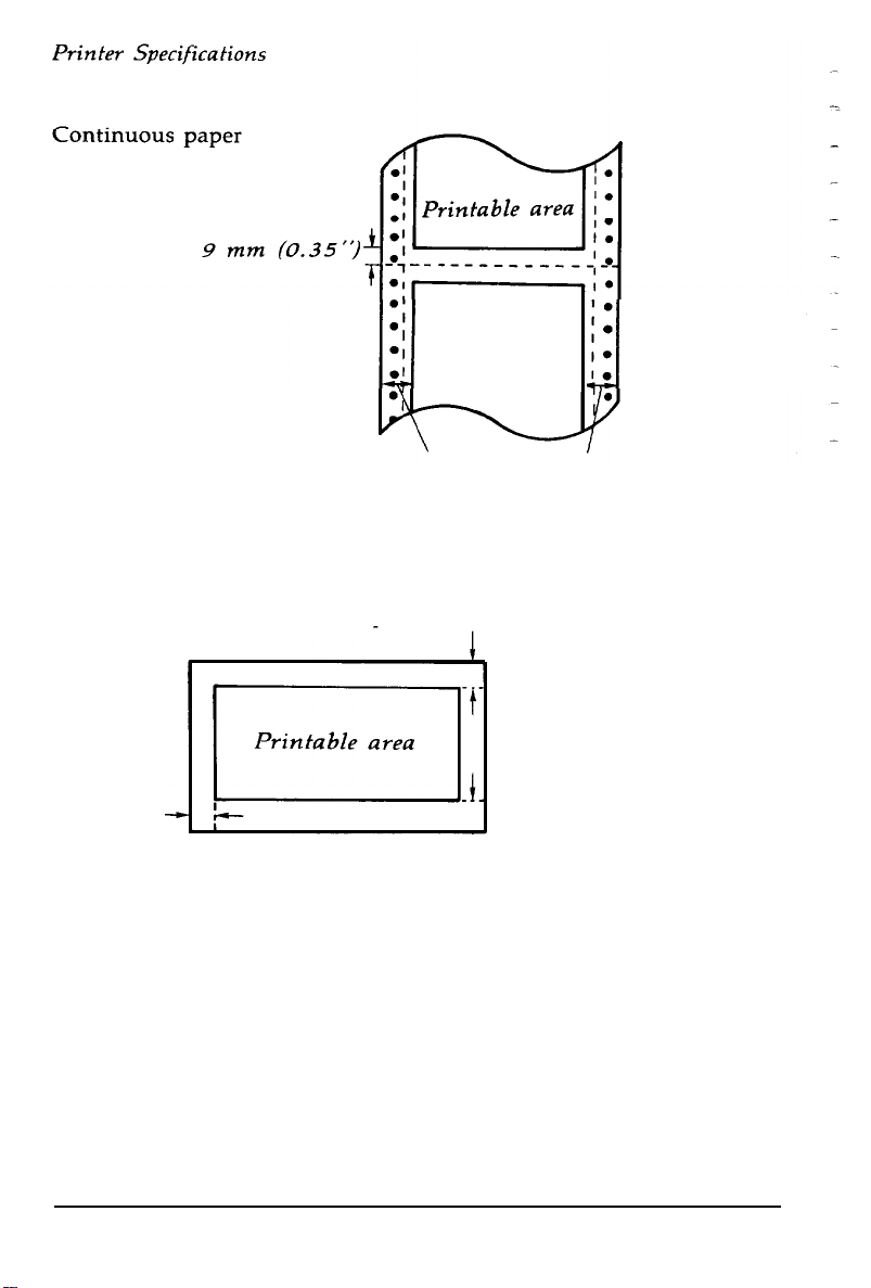
Printable area
13 mm (0.51 inch) or more (both sides) when the 101 mm to
242 mm (4 to 9.5 inch) width paper is used. 26 mm (1.02
inch) or more (left side) and 24 mm (0.94 inch) or more
(right side) when the 254 mm (10 inch) width paper is used.
Envelope
8.5
mm
(0.33")
or more
22 mm (0.87”)
3 mm (0.12")
or more
Paper thickness:
Single sheet
0.065
to
0.140
or more
mm
(0.0025
to
0.0055”)
Continuous paper
0.065
to
0.250
mm
(0.0025
to
0.0098”)
Roll paper
0.070
to
0.090
mm
(0.0028
to
0.0035”)
Envelope
0.160
to
0.520
mm
(0.0063
to
0.0197”)
Label
0.160
to
0.190
mm
(0.0063
to
0.0075”
including the base sheet)
7-4
Technical Specification
Page 100

Paper weight: Single sheet
52
g/m2 to
Continuous paper
52
g/m2 to
Multi-part forms
[45
g/m2 to
([12
lb to
N<3
Roll paper
52
g/m2 to
(14
lb to
Envelope
45 g/m2 to 90 g/m
(12
lb to 24 lb)
90
82
15
64
17
g/m2 (14
g/m2 (14
58
g/m2] X N
lb] X N)
2
g/m
lb)
2
Printer Specifications
lb to
24
lb)
lb to
22
lb)
Number of copies:
With continuous multi-part paper only; one
original plus up to two copies. Maximum
thickness: 0.25 mm (0.01 inch).
Note
l Print on 90 g/m
l Printing on labels made of pressure sensitive paper jointed by
2
(24 lb) paper only at normal temperature.
perforations or pasting and with a total thickness of up to 0.3
mm (0.012”) is possible only when temperature is between 5°C
to 35°C and 10% to 80% relative humidity.
Mechanical
Paper-feed methods:
Ribbon: Black ribbon cartridge #8750
Friction
Push tractor
Pull tractor (optional)
Cut-sheet feeder (optional)
Roll-paper holder (optional)
Life expectancy at 14 dots/character:
3 million characters
Technical Specification 7-5
 Loading...