

Page 1
EPSON
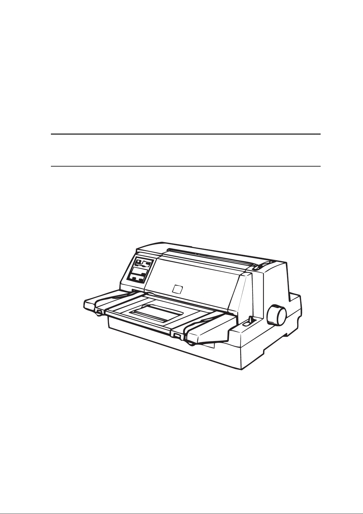
IMPACT DOT MATRIX PRINTER
SERVICE MANUAL
EPSON LQ-670
SEIKO EPSON CORPORATION
4007875
Page 2

NOTICE
All rights reserved. Reproduction of any part of this manual in any form whatsoever
without SEIKO EPSON’s express written permission is forbidden.
The contents of this manual are subjects to change without notice.
All efforts have been made to ensure the accuracy of the contents of this manual.
However, should any errors be detected, SEIKO EPSON would greatly appreciate
being informed of them.
The above notwithstanding SEIKO EPSON can assume no responsibility f or any errors
in this manual or the consequences thereof.
EPSON is a registered trademark of SEIKO EPSON CORPORATION.
General Notice:
Other product names used herein are for identification purposes only and may be
trademarks or registered trademarks of their respective companies.
Copyright 1997 by SEIKO EPSON CORPORATION
Nagano, Japan
ii
Page 3

PRECAUTIONS
Precautionary notations throughout the text are categorized relative to 1) personal injury and 2)
damage to equipment.
WARNING
CAUTION
The precautionary measures itemized below should always be observed when performing
repair/maintenance procedures.
Signals a precaution which, if ignored, could result in serious or fatal personal injury.
Great caution should be exercised in performing procedures preceded by
WARNING Headings.
Signals a precaution which, if ignored, could result in damage to equipment.
WARNING
1. ALWAYS DISCONNECT THE PRODUCT FROM BOTH THE POWER SOURCE AND
PERIPHERAL DEVICES PERFORMING ANY MAINTENANCE OR REPAIR PROCEDURES.
2. NO WORK SHOULD BE PERFORMED ON THE UNIT BY PERSONS UNFAMILIAR WITH
BASIC SAFETY MEASURES AS DICTATED FOR ALL ELECTRONICS TECHNICIANS IN
THEIR LINE OF WORK.
3. WHEN PERFORMING TESTING AS DICTATED WITHIN THIS MANUAL. DO NOT
CONNECT THE UNIT TO A POWER SOURCE UNTIL INSTRUCTED TO DO SO. WHEN THE
POWER SUPPLY CABLE MUST BE CO NNECTED, USE EXT REME CAUT ION IN W O RKING
ON POWER SUPPLY AND OTHER ELECTRONIC COMPONENTS.
CAUTION
1. REPAIRS ON EPSON PRODUCT SHOULD BE PERFORMED O NLY BY EPSON CERTIFIED
REPAIR TECHNICIAN.
2. MAKE CERTAIN THAT T HE SOURCE VOLT AGE IS THE SAME AS T HE RATED VOLT AGE,
LISTED ON THE SERIAL NUMBER/RATING PLATE. IF THE EPSON PRODUCT HAS A
PRIMARY AC RATING DIFFERENT FROM AVAILABLE POWER SOURCE, DO NOT
CONNECT IT TO THE POWER SOURCE.
3. ALWAYS VERIFY THAT T HE EPSON PRODUCT HAS BEEN DISCONNECT ED FROM THE
POWER SOURCE BEFORE REMOVING OR REPLACING PRINTED CIRCUIT BOARDS
AND/OR INDIVIDUAL CHIPS.
4. IN ORDER TO PROTECT SENSITIVE MICROPROCESSORS AND CIRCUITRY, USE
STATIC DISCHARGE EQUIPMENT, SUCH AS ANTI-STATIC WRIST STRAPS, WHEN
ACCESSING INTERNAL COMPONENTS.
5. REPLACE MALFUNCTIONING COMPONENTS ONLY WITH THOSE COMPONENTS BY
THE MANUFACTURE; INTRODUCTION OF SECOND-SOURCE ICs OR OTHER
NONAPPROVED COMPONENTS MAY DAMAGE THE PRODUCT AND VOID ANY
APPLICABLE EPSON WARRANTY.
iii
Page 4

PREFACE
This manual descr ibes functions , theory of electrical and m echanical operations , maintenanc e, and
repair of EPSON LQ-670.
The instructions and procedur es included herein are intended for the experience r epair technician,
and attention should be given to die precautions on the preceding page. The Chapters are
organized as follows:
CHAPTER 1. GENERAL DESCRIPTION
Provides a general product overview, lists specifications, and illustrates the main components of the
printer.
CHAPTER 2. OPERATING PRINCIPLES
Describes the theory of printer operation.
CHAPTER 3. DISASSEMBLY AND ASSEMBLY
Includes a step-by-step guide for product disassembly and assembly.
CHAPTER 4. ADJUSTMENT
Includes a step-by-step guide for adjustment.
CHAPTER 5. TROUBLESHOOTING
Provides EPSON-approved techniques for troubleshooting.
CHAPTER 6. MAINTENANCE
Describes preventive maintenance techniques and lists lubricants and adhesives required to
service the equipment.
APPENDIX
Describes connector pin assignments, circuit diagrams, circuit board component layout and
exploded diagram.
The contents of this manual are subject to change without notice.
iv
Page 5

REVISION SHEET
Revision Issued Data Contents
Rev. A May 28, 1997 First issue
v
Page 6

TABLE OF CONTENTS
CHAPTER 1. GENERAL DESCRIPTION
CHAPTER 2. OPERATING PRINCIPLES
CHAPTER 3. DISASSEMBLY AND ASSEMBLY
CHAPTER 4. ADJUSTMENT
CHAPTER 5. TROUBLESHOOTING
CHAPTER 6. MAINTENANCE
APPENDIX
vi
Page 7

Chapter 1
Product Descriptions
1.1 Specifications.......................................................................................................1-1
1.1.1 Features................................................................................................................................... 1-1
1.2 Hardware Specifications......................................................................................1-3
1.2.1 Printing Method ...................................................................................................................... 1-3
1.2.2 Printing Specifications........................................................................................................... 1-4
1.2.3 Paper Handling Specifications.............................................................................................. 1-5
1.2.4 Paper Specification ................................................................................................................ 1-6
1.2.5 Printable Area ....................................................................................................................... 1-10
1.2.6 Ribbon Cartridge .................................................................................................................. 1-14
1.2.7 Input data buffer................................................................................................................... 1-14
1.2.8 Electrical Specification ........................................................................................................ 1-14
1.2.9 Reliability............................................................................................................................... 1-14
1.2.10 Environmental Condition................................................................................................... 1-15
1.2.11 Safety Approvals................................................................................................................. 1-15
1.2.12 CE Marking.......................................................................................................................... 1-15
1.2.13 Acoustic Noise.................................................................................................................... 1-15
1.3 Firmware Specification ......................................................................................1-16
1.3.1 Control Codes and Fonts..................................................................................................... 1-16
1.3.2 Interface Specification ......................................................................................................... 1-18
1.3.2.1 Parallel interface (Forward channel) .......................................................................1-18
1.3.2.2 Parallel Interface (Reverse channel).......................................................................1-20
1.3.2.3 Optional Interface....................................................................................................1-21
1.3.2.4 Interface Selection................................................................................................... 1-21
1.3.2.5 Manual selection...................................................................................................... 1-21
1.3.2.6 Automatic selection .................................................................................................1-21
1.3.2.7 Interface state and interface selection.....................................................................1-21
1.3.3 Prevention Hosts from Data Transfer Timeout.................................................................. 1-21
1.4 Operation.............................................................................................................1-22
1.4.1 Control Panel ........................................................................................................................ 1-22
1.4.1.1 Usual Operation ...................................................................................................... 1-22
1.4.1.2 Switches.................................................................................................................. 1-24
1.4.1.3 Indicators(LED) ....................................................................................................... 1-25
1.4.1.4 Buzzer .....................................................................................................................1-26
1.4.2 Default Setting ...................................................................................................................... 1-27
1.4.3 Bi-d Adjustment.................................................................................................................... 1-28
1.4.4 Initialization........................................................................................................................... 1-29
1.4.5 Errors..................................................................................................................................... 1-29
1.5 Main Components...............................................................................................1-30
1.5.1 C214 Main Board .................................................................................................................. 1-30
1.5.2 C214PSB Board .................................................................................................................... 1-30
1.5.3 C214 PNL Board.................................................................................................................... 1-31
1.5.4 Printer Mechanism ............................................................................................................... 1-31
1.5.5 Housing ................................................................................................................................. 1-31
Page 8
Chapter 1 Product Description
1.1 Specifications
This specifications provide characteristics of the serial impact dot matrix printer LQ-670.
1.1.1 Features
LQ-670 is a 24pin serial impact dot matrix printer for the VAR(value added reseller) market.
The major features of this printer are;
Columns :106 columns (10cpi)
Printing Speed :High speed draft 300cps
:Draft 250cps
:LQ 83cps at 10cpi
Feeding Method :Friction feed (front manual, rear CSF)
:Push tractor feed (rear)
Feeder :Rear push tractor
CSF Bin1/Bin2 (Option)
Roll paper holder (Option)
Paper/Media :Single sheet, Continuous paper, Multi part paper, Envelope, Card,
Label and Roll paper.
Fonts :9LQ & 1 Draft Bitmap and 4 Scarable typefaces
:8 Bar code fonts
Character tables :Standard version 11 tables
NLSP version 20 tables
Input buffer :64 Kbytes
Acoustic noise :55dB(A) (ISO7779 pattern)
Reliability :Total print volume 6.5 million lines(except print head)
:(MTBF) 5000 POH
:Print head life 200 million strokes/wire
:Ribbon life 2 million characters
Interface :Bi-directional parallel interface (IEEE-1284 nibble mode supported)
Type B/I/F level 2 (Option)
Control code :ESC/P 2 and IBM 2390 Plus emulation
Copy capability :1 original + 4 copies
Control panel functions :Font, Condensed, Pause, Tear off, Bin, LF/FF, Load/Eject, Micro Adjust
and the default settings
Printable area :70 lines are available at A4.
(Top margin 0 mm setting and Bottom margin 0 mm setting are available)
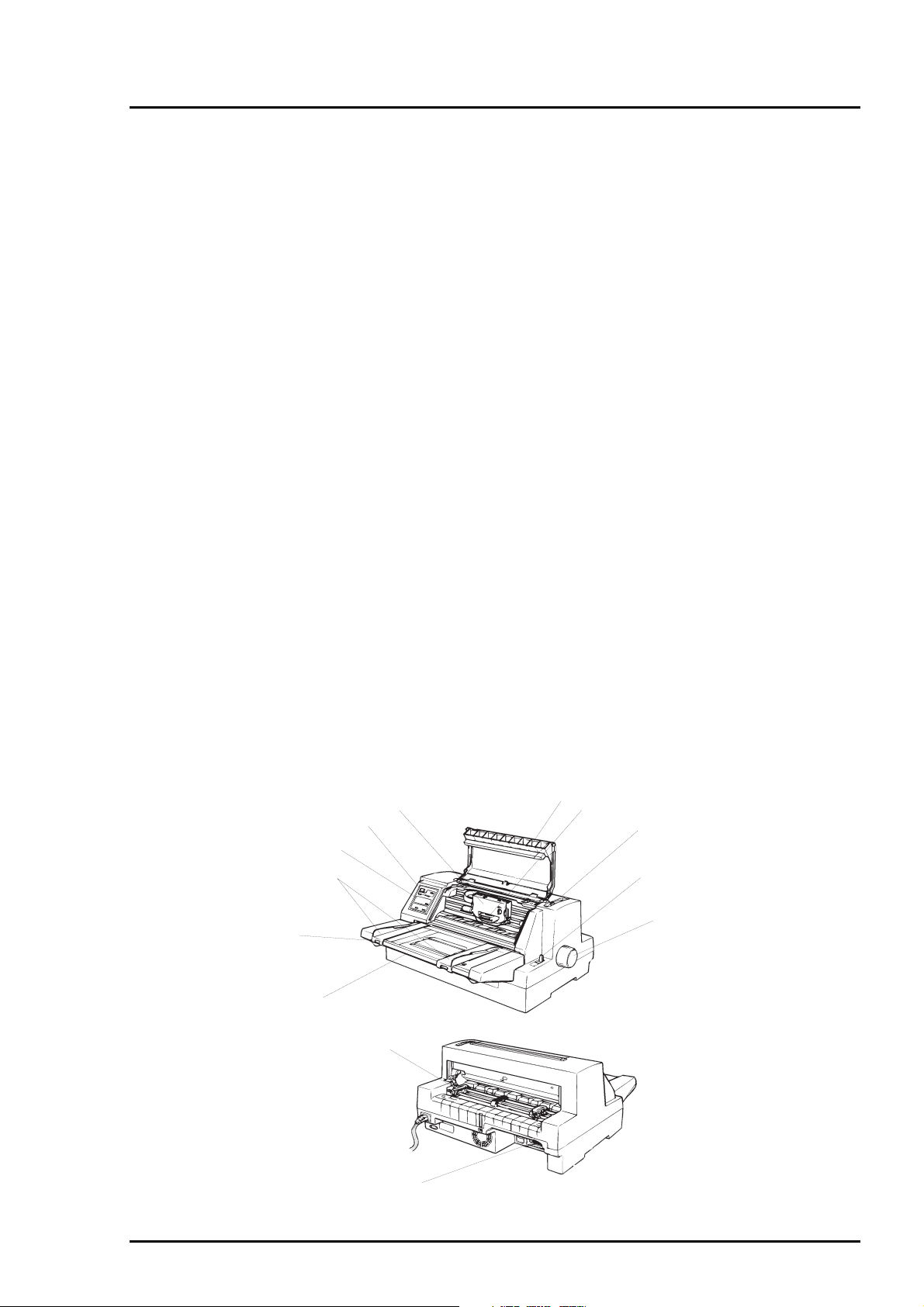
Control Panel
Edge Guide
Stacker
Paper Guide
Ribbon Cartridge
Power Switch
Push Tractor
I/F Connector
Printer Cover
Print Head
Adjust Lever
Release lever
Paper Feed Knob
Figure 1-1. Exterior of LQ-670
Rev. A
1-1
Page 9
LQ-670 Service Manual
2
Consumables and optional units
Table 1-1. Consumables and Optional Units
Name Part Number
Ribbon cartridge S015016
High capacity cut sheet feeder (Bin1) C806781 (EAI version)
High capacity cut sheet feeder (Bin1) C806782 (Non-EAI version)
Second bin cut sheet feeder (Bin2) C806791 (EAI version)
Second bin cut sheet feeder (Bin2) C806792 (Non-EAI version)
Roll paper holder #8310
Serial I/F card C82305* / C82306*
32KB intelligent serial I/F card C82307* / C82308*
32KB intelligent parallel I/F card C82310* / C82311*
Local Talk I/F card C82312*
32KB IEEE-488 I/F card C82313*
Coax I/F card C82314*
Twinax I/F card C82315*
Ethernet I/F card C82331*
IEEE-1284 parallel I/F card C82345*
Multi Protocol Ethernet I/F card C82346*
Note*)
: The number represented by an asterisk varies, depending on the country.
1-
Rev. A
Page 10
3
1.2 Hardware Specifications
This section describes hardware specification for the LQ-670.
1.2.1 Printing Method
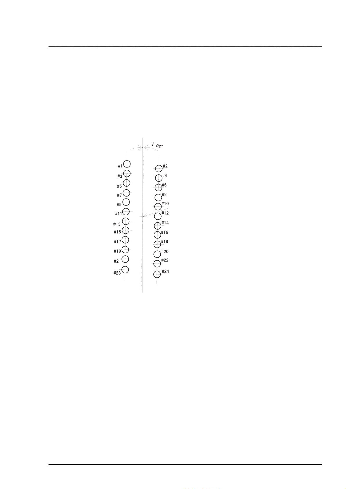
Printing Method : Impact dot matrix
Number of pins : 24 pins
Print pin arrangement : 12x2 staggered
Print pin diameter : 0.0079 inch (0.20 mm)
Color : Black
Print direction : Bi-direction with logic seeking
Chapter 1 Product Description
Head Center
Figure 1-2. Pin Configuration
Rev. A
1-
Page 11
LQ-670 Service Manual
4
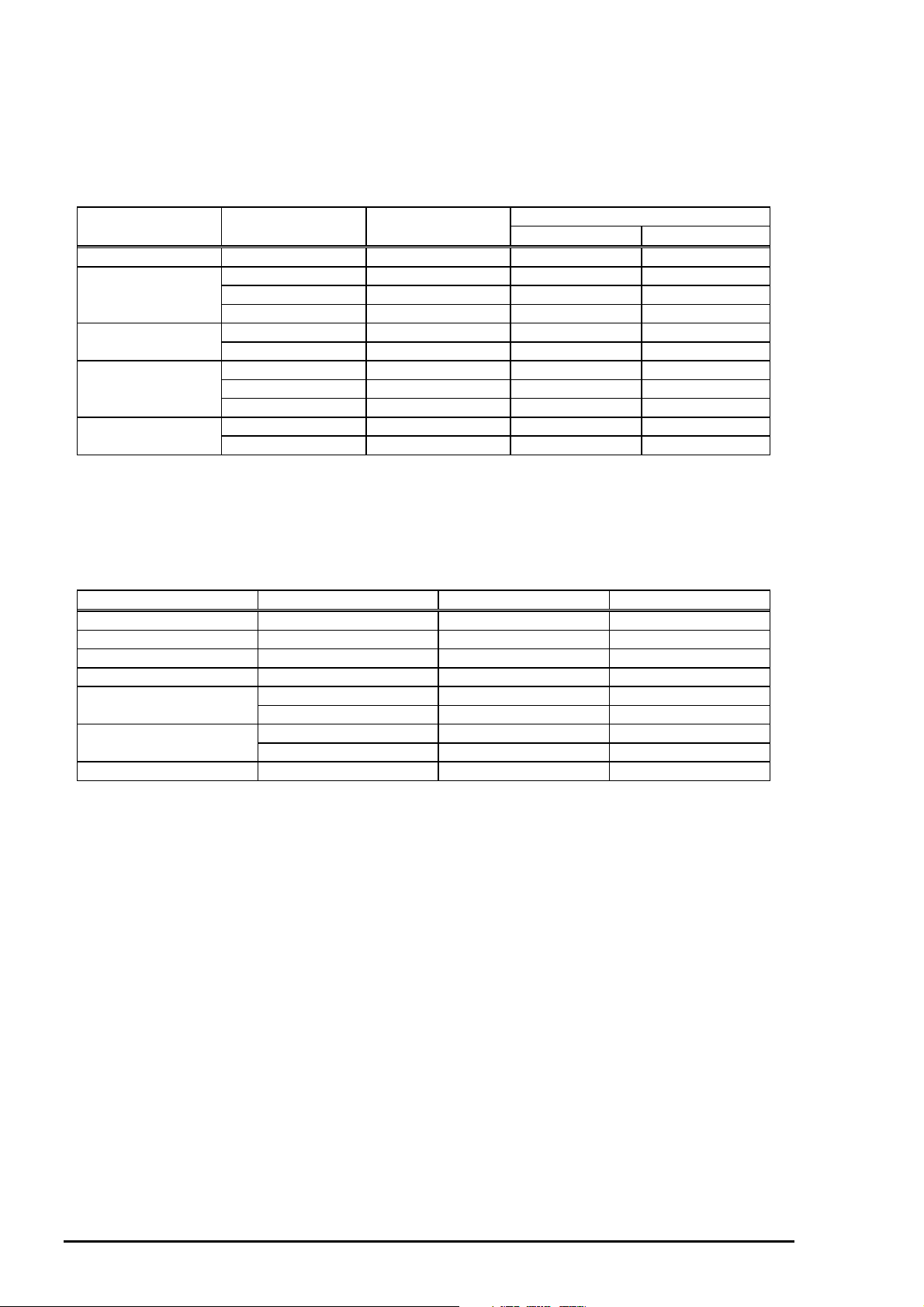
1.2.2 Printing Specifications
Copy capability :1 original + 4 copies
Print speed and printable columns
Table 1-2. Print Speed and Printable Columns
Printing Mode Character Pitch Printable Columns Print Speed(cps)
Normal Copy
High speed Draft 10cpi 106 300 200
Draft 10cpi 106 250 167
12cpi 127 300 200
15cpi 159 375 250
Draft condensed 17cpi 181 214 143
20cpi 212 250 167
LQ 10cpi 106 83 70
12cpi 127 100 83
15cpi 159 125 104
LQ condensed 17cpi 181 143 119
20cpi 212 167 139
Note)
Note)
When the power supply voltage drops to the lower limit, the printer stops printing and then starts
printing the rest of that line again but at the slower speed than before.
When the head temperature rises to the upper limit, the printer stops printing. When the head
temperature falls to the normal level, the printer starts printing again but slower than before.
Resolution
Table 1-3. Resolution
Printing Mode Horizontal density Vertical density Adjacent dot print
High speed draft 90dpi 180dpi No
Draft 120dpi 180dpi No
Draft condensed 240dpi 180dpi No
LQ 360dpi 180dpi N0
8 pins bit image 60, 80, 90 or 120dpi 60dpi Yes
120 or 240dpi 60dpi No
24 pins bit image 60,90,120 or 180dpi 180dpi Yes
360dpi 180dpi No
Raster graphics 180 or 360dpi 180 or 360dpi Yes
Control code : ESC/P 2 and IBM 2390 Plus emulation (Refer to control code)
1-
Rev. A
Page 12
Chapter 1 Product Description
5
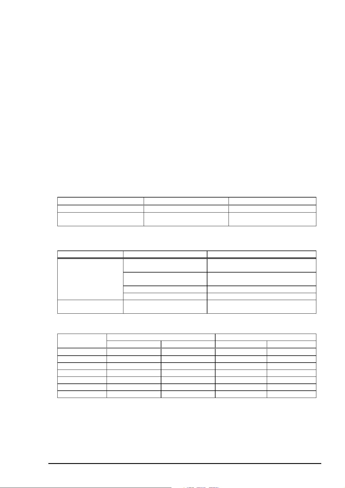
1.2.3 Paper Handling Specifications
Feeding method :Friction feed (front manual, rear CSF)
Push tractor feed (rear)
Feeder :Rear push tractor
CSF Bin1/Bin2 (Option)
Roll paper holder(Option)
Paper path :Manual Insertion Front in, front out
CSF Rear in, front out
Tractor Rear in, front out
Line Spacing :1/6 inch or programmable in increments of 1/360 inch
Feed speed :Refer to the table 1-4.
Release Lever :The release lever must be set according to the table 1-5.
Paper thickness lever :The paper thickness lever must be set at the proper position according to the
table 1-6.
Table 1-4. Feeding Speed
Normal mode Copy mode
1/6 inch feed 60 msec 70 msec
Continuous feed 0.127MPS(m/sec)
5.0 IPS(inches/sec)
Table 1-5. Release Lever Position
Lever Position Paper path/Feeder Paper/Media
Friction Manual insertion(front) Cut sheet(Single sheet& Muti part)
Card
CSF Bin1 Cut sheet(Single sheet & Multi part)
Envelope, Card
CSF Bin2 Cut sheet(Single sheet)
Roller paper holder Roll paper
Tractor Push tractor feed(rear) Continuous paper(Single sheet & Multi
part)
Table 1-6. Paper Thickness Lever Position
Lever Position Paper thickness (inch) Paper thickness (mm)
Minimum Maximum Minimum Maximum
0 0.0024 0.0047 0.065 0.12
1 0.0047 0.0075 0.12 0.19
2 0.0075 0.0102 0.19 0.26
3 0.0102 0.0126 0.26 0.32
4 0.0126 0.0142 0.32 0.36
5 0.0142 0.0157 0.36 0.40
6 0.0157 0.0205 0.40 0.52
0.092 MPS(m/sec)
3.6 IPS(inches/sec)
Rev. A
1-
Page 13
LQ-670 Service Manual
6
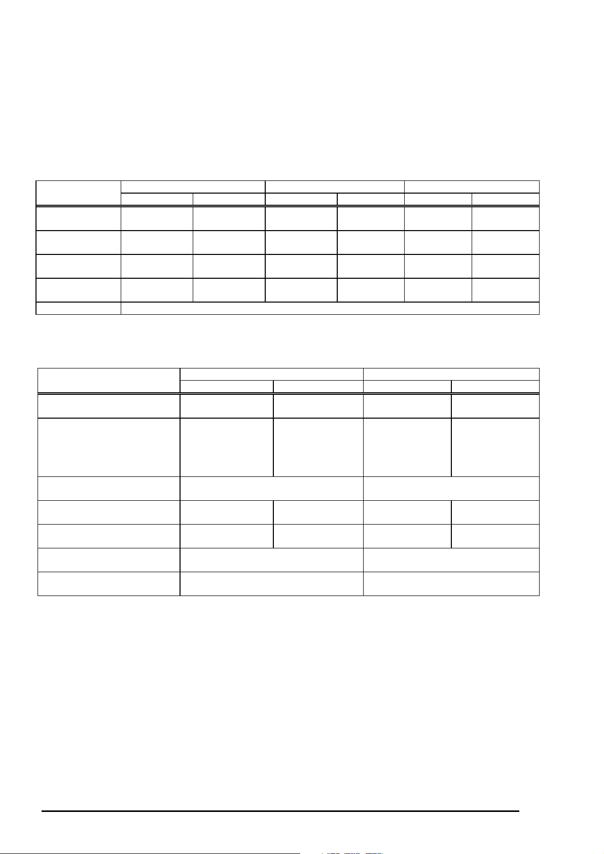
1.2.4 Paper Specification
This section describes printable area and types of paper that can be used in this printer.
Cut Sheets
The following table shows specification for cut sheets.
Table 1-7. Cut Sheet (Single sheet, Not Multi Part)
Front Entry(Manual Insertion) Rear Entry(CSF bin1) Rear Entry(CSF bin2)
Minimum Maximum Minimum Maximum Minimum Maximum
Width (inch) 3.6 11.7 3.9 11.7 3.9 11.7
(mm) 91 297 100 297 100 297
Length (inch) 3.5 16.5 3.6 16.5 8.3 16.5
(mm) 90 420 92 420 210 420
Thickness(inch) 0.0025 0.0055 0.0025 0.0055 0.0025 0.0055
(mm) 0.065 0.14 0.065 0.14 0.065 0.14
Weight (g/m2)529052905290
(lb) 14 24 14 24 14 24
Quality Plain paper, Reclaimed paper, Not curled, not folded, not crumpled.
Note):
Printing on reclaimed paper is available only under the normal temperature and humidity condition.
Table 1-8. Cut Sheet (Multi Part)
Front Entry (Manual Insertion) Rear Entry (CSF)
Minimum Maximum Minimum Maximum
Width (inch) 3.6 11.7 3.9 11.7
(mm) 91 297 100 297
Length (inch) 3.5 16.5(11.7) 3.6 16.5
(mm) 90 420(297)
( ):Value of line
glue one side of
form.
Copies 1 original + 4 copies 1 original + 4 copies
Total thickness (inch) 0.0047 0.015 0.0047 0.015
(mm) 0.12 0.39 0.12 0.39
Weight (g/m2)40 58 40 58
(one sheet of multi part) (lb) 12 15 12 15
Quality Plain paper, Reclaimed paper
Not curled, not folded, not crumpled
Jointing Line glue at the top or one side of
form
Note):
Printing on multi part. Don’t use CSF 2nd bin.
Plain paper, Reclaimed paper
Not curled, not folded, not crumpled
Line glue at the top of form
92 420
1-
Rev. A
Page 14
Chapter 1 Product Description
7
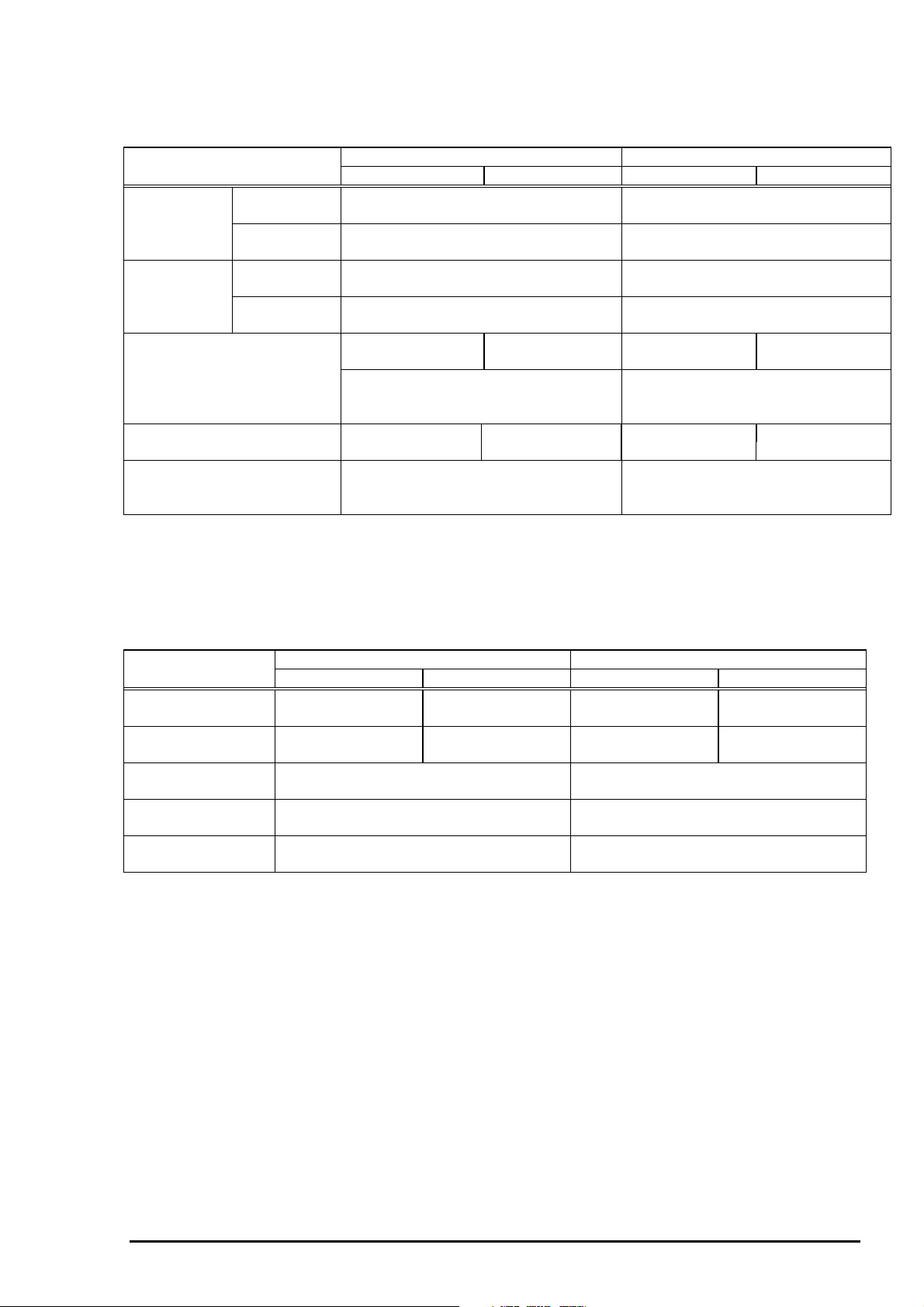
Envelope
Table 1-9. Envelope Specification
Front Entry (Manual Insertion) Rear Entry (CSF)
Minimum Maximum Minimum Maximum
Envelope Width (inch) 6.5 6.5
(No.6) (mm) 165 165
Length (inch) 3.6 3.6
(mm) 92 92
Envelope Width (inch) 9.5 9.5
(No.10) (mm) 241 241
Length (inch) 4.1 4.1
(mm) 105 105
Total thickness (inch) 0.0063 0.0197 0.0063 0.0197
(mm) 0.16 0.52 0.16 0.52
The difference of thickness at the
printable area is within 0.0098 inch
(0.25mm)
Weight (g/m2)45 91 45 91
(lb) 12 24 12 24
Quality BOND paper, PLANE paper or AIR
MAIL. No glue at a flap, Not curled,
not folded, not crumpled
The difference of thickness at the
printable area is within 0.0098 inch
(0.25mm)
BOND paper, PLANE paper or AIR
MAIL. No glue at a flap, Not curled,
not folded, not crumpled
Note1)
: Printing on envelope is available only under normal temperature and humidity conditions.
Note2):
Note3):
Card
Width (inch) 4.1 5.8 4.1 5.8
Length (inch) 4.1 5.83 4.1 5.8
Thickness (inch) 0.0087 0.0087
Weight (g/m2) 192 192
Quality Plain paper, Reclaimed paper
Note1)
Note2):
Set the longer side of envelope horizontally.
Don’t use CSF 2nd bin.
Table 1-10. Card Specification
Front Entry (Manual Insertion) Rear Entry(CSF)
Minimum Maximum Minimum Maximum
(mm) 105 148 105 148
(mm) 105 148 105 148
(mm) 0.22 0.22
(lb) 51 51
Plain paper, Reclaimed paper
Not curled, not folded, not crumpled
: Printing card is available only under normal temperature and humidity conditions.
Don’t use CSF 2nd bin.
Not curled, not folded, not crumpled
Rev. A
1-
Page 15
LQ-670 Service Manual
8
Continuous paper (Single sheet and Multi part)
Table 1-11. Continuous Paper (Single Sheet and Multi Part)
Rear Entry (Tractor)
Minimum Maximum
Width (inch) 4 12
(mm) 101.6 304.8
Length(one page) (inch) 4 22
(mm) 101.6 558.8
Copies 1 original + 4 copies
Total thickness (inch) 0.0025 0.015
(mm) 0.065 0.39
Weight (g/m2)52 82
(not multi part) (lb) 14 22
Weight (g/m2)40 58
(one sheet of multi part) (lb) 12 15
Quality Plain paper, Reclaimed paper
Carbonless multi part paper
Jointing Point glue or paper staple(both side)
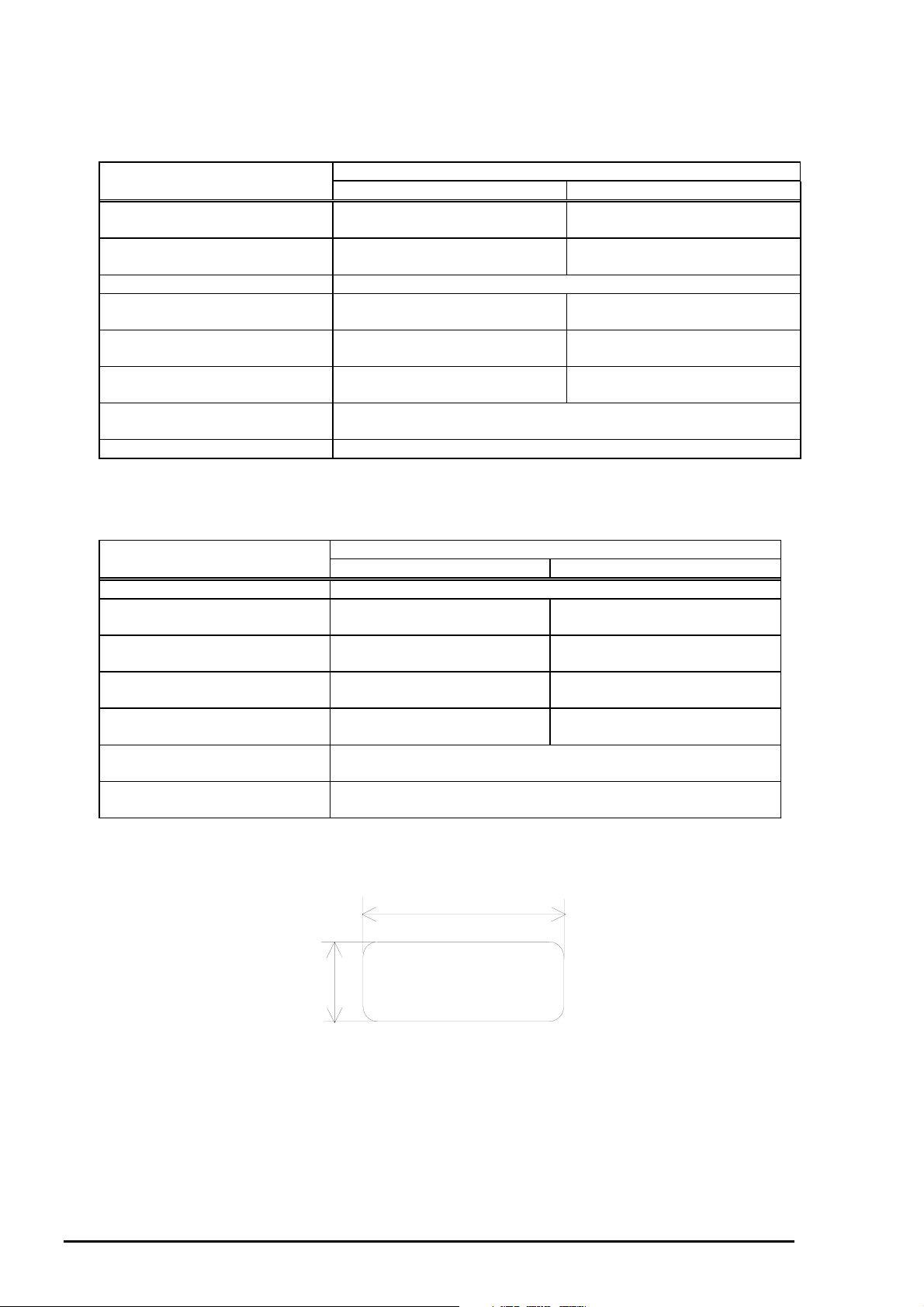
Continuous paper with Labels
Table 1-12. Continuous Paper with Labels
Rear Entry (Tractor)
Minimum Maximum
Label size See the figure below.
Base sheet width (inch) 4 12
(mm) 101.6 304.8
Base sheet length (inch) 4 22
(one page) (mm) 101.6 558.8
Base sheet (inch) 0.0028 0.0035
Thickness (mm) 0.07 0.09
Total thickness (inch) 0.0063 0.0075
0.16 0.19
Label weight (g/m2)68
(lb) 17
Quality A VERY CONTINUOUS FORM LABELS, A VERY MINI-LINE
LABELS or the same quality labels
Note)
: Printing on label is available only under the normal temperature and humidity conditions.
Note):
The base sheet of labels must be continuous paper.
2.5 inch (63.5mm) min.
15/16 inch
(23.8mm)
min.
Label
R 0.1 inch(2.5mm) min.
Figure 1-3. Label Size
1-
Rev. A
Page 16

Chapter 1 Product Description
9
Roll paper
Table 1-13. Roll Paper Specification
Rear Entry (Roll paper holder)
Minimum Maximum
Width (inch) 8.5
(mm) 216
Length (inch) -----
(mm)
Thickness (inch) 0.0028 0.0035
(mm) 0.07 0.09
Weight (g/m2)52 82
(lb) 14 22
Quality Plain paper, Reclaimed paper. Not curled, not folded, not
crumpled.
Rev. A
1-
Page 17
LQ-670 Service Manual
0
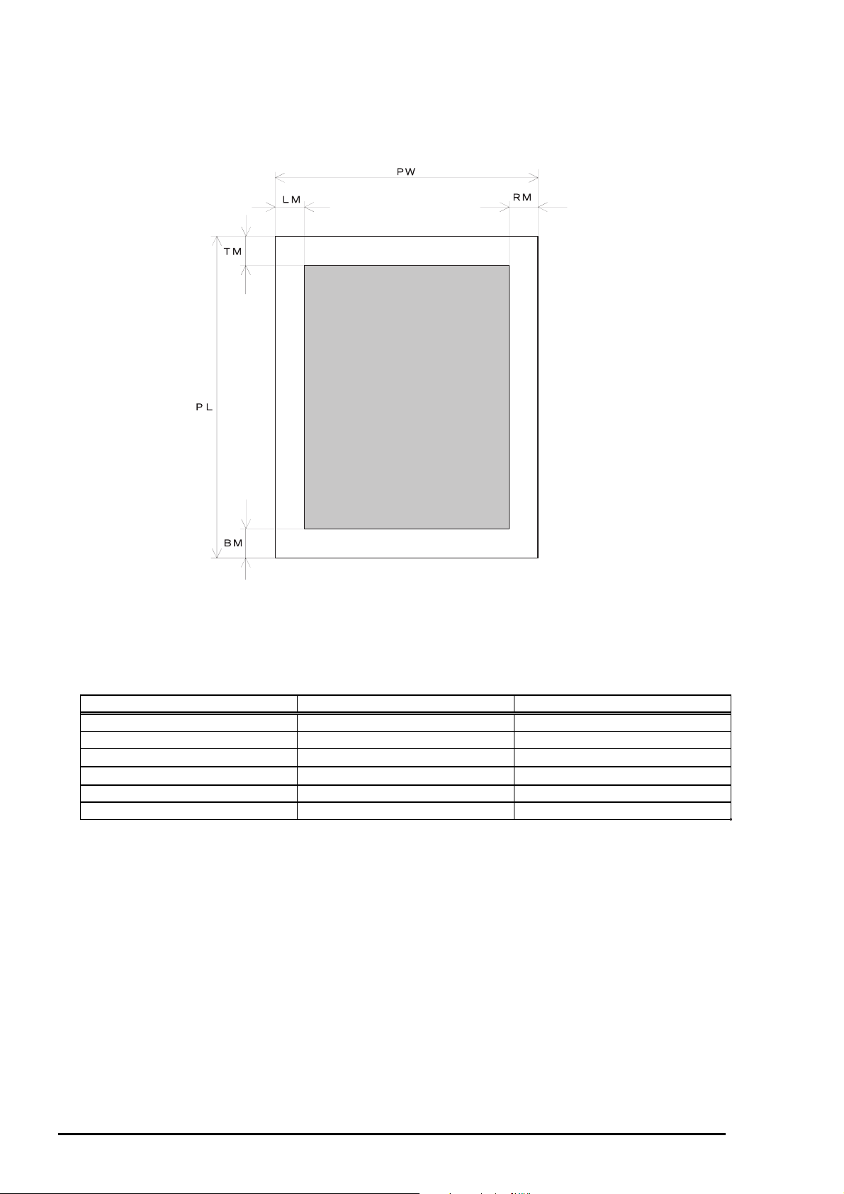
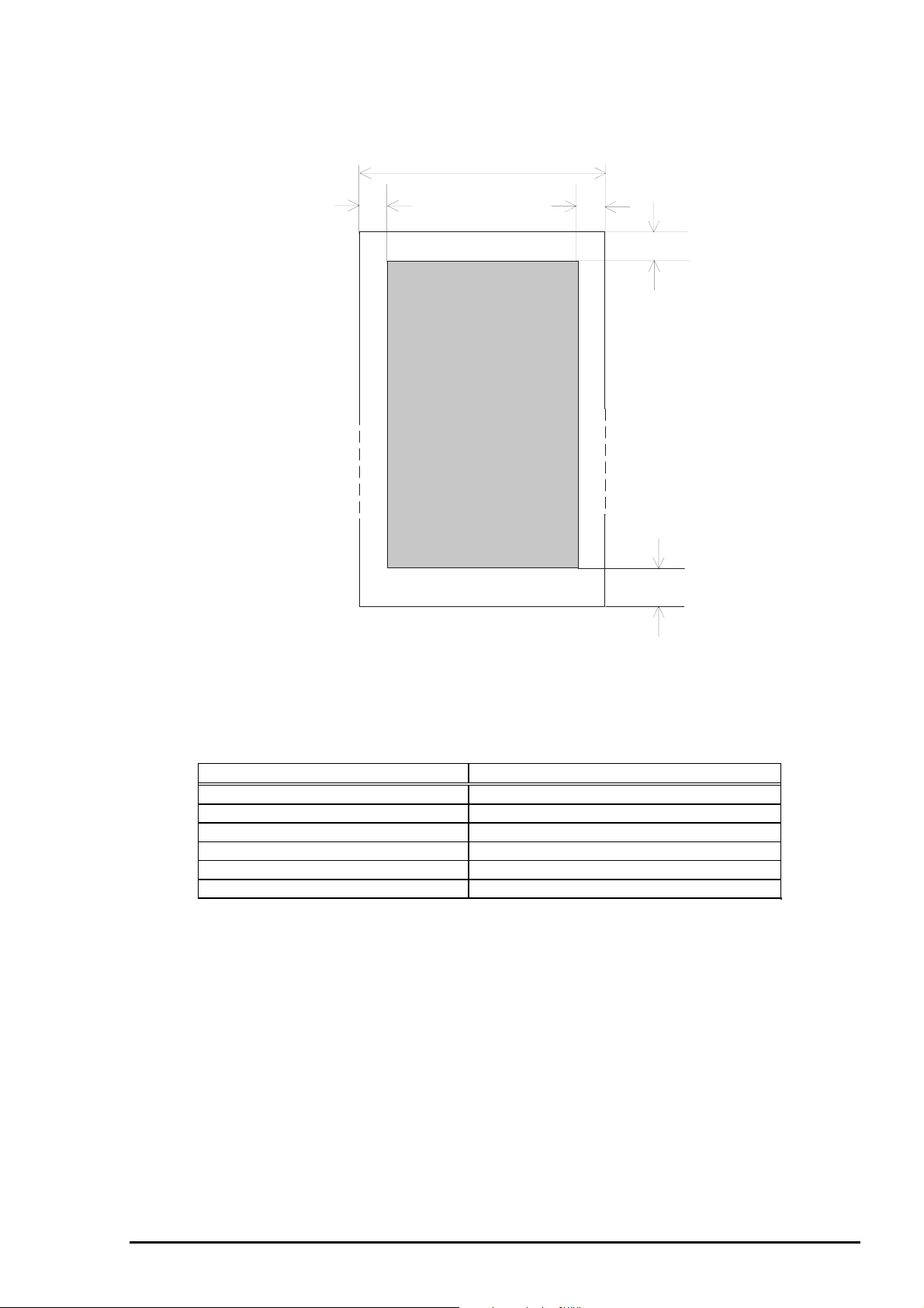
1.2.5 Printable Area
Cut sheets
Printable Area
Figure 1-4. Printable Area for Cut Sheet
Table 1-14. Printable Area for Cut Sheet
Single sheet Multi part
PW (Width) (Refer to section 1.2.4) (Refer to section 1.2.4)
PL (Length) (Refer to section 1.2.4) (Refer to section 1.2.4)
LM (Left margin)
RM (Right margin)
TM (Top margin) 0.0mm or more 0.0mm or more
BM (Bottom margi n) 0.0mm or more 0. 0mm or more
3 mm or more(PW<=297mm) 3 mm or more(PW<=297mm)
3 mm or more(PW<=297mm) 3 mm or more(PW<=297mm)
1-1
Rev. A
Page 18
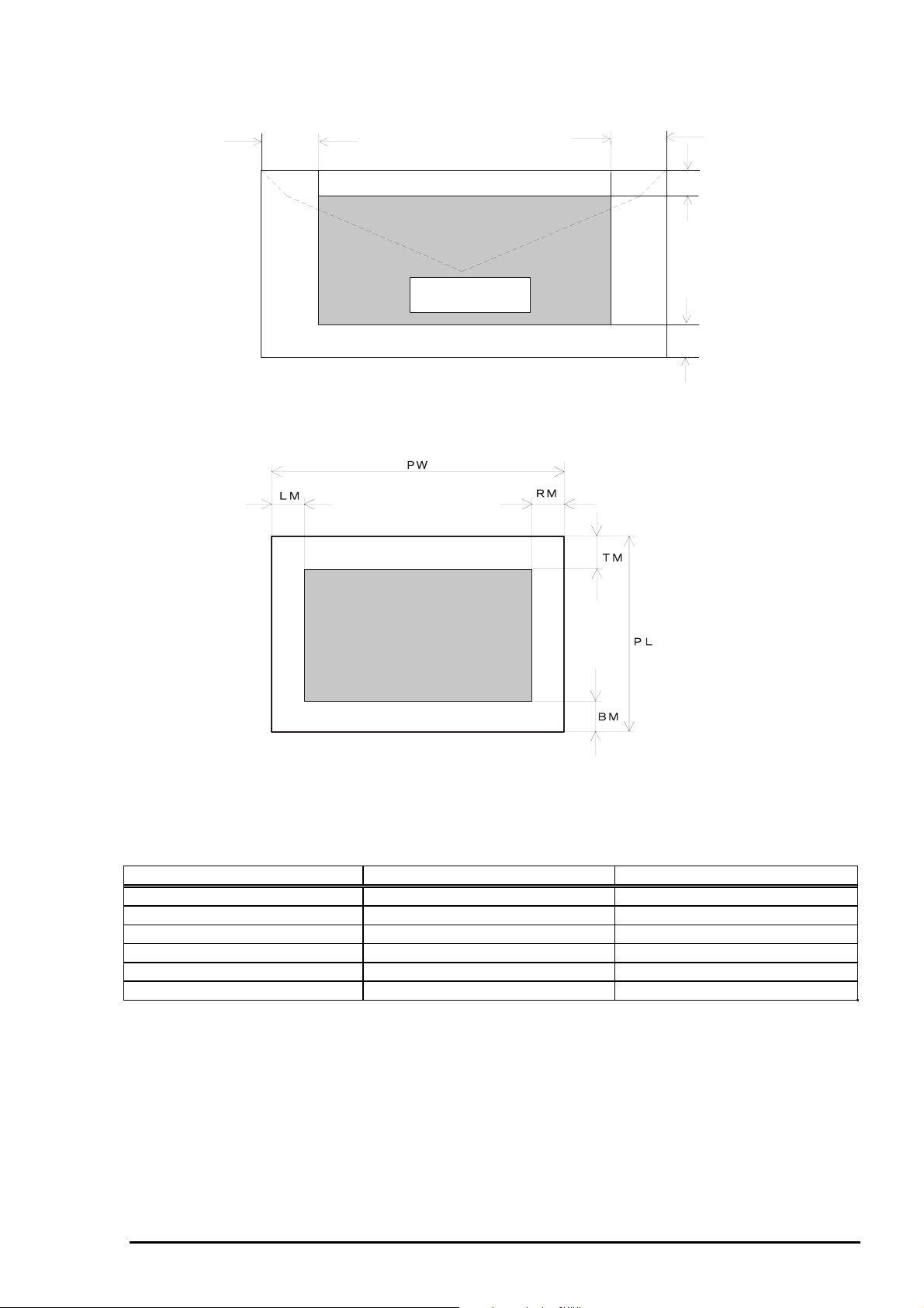
Envelope and card
Chapter 1 Product Description
LM
RM
TM
Printable Area
BM
Figure 1-5. Printable Area for Envelope
Printable Area
Figure 1-6. Printable Area for Card
Table 1-15. Printable Area for Envelope and Card
Envelope Card
PW (Width) (Refer to section 1.2.4) (Refer to section 1.2.4)
PL (Length) (Refer to section 1.2.4) (Refer to section 1.2.4)
LM (Left margin) 3 mm or more 3 mm or more
RM (Right margin) 3 mm or more 3 mm or more
TM (Top margin) 0.0mm or more *1 0.0mm or more *1
BM (Bottom margi n) 0.0mm or more 0.0mm or more
Note *1)
: When loading the paper from CSF, TM(Top margin) is 4.2 mm or more.
Rev. A
1-1 1
Page 19
LQ-670 Service Manual
2
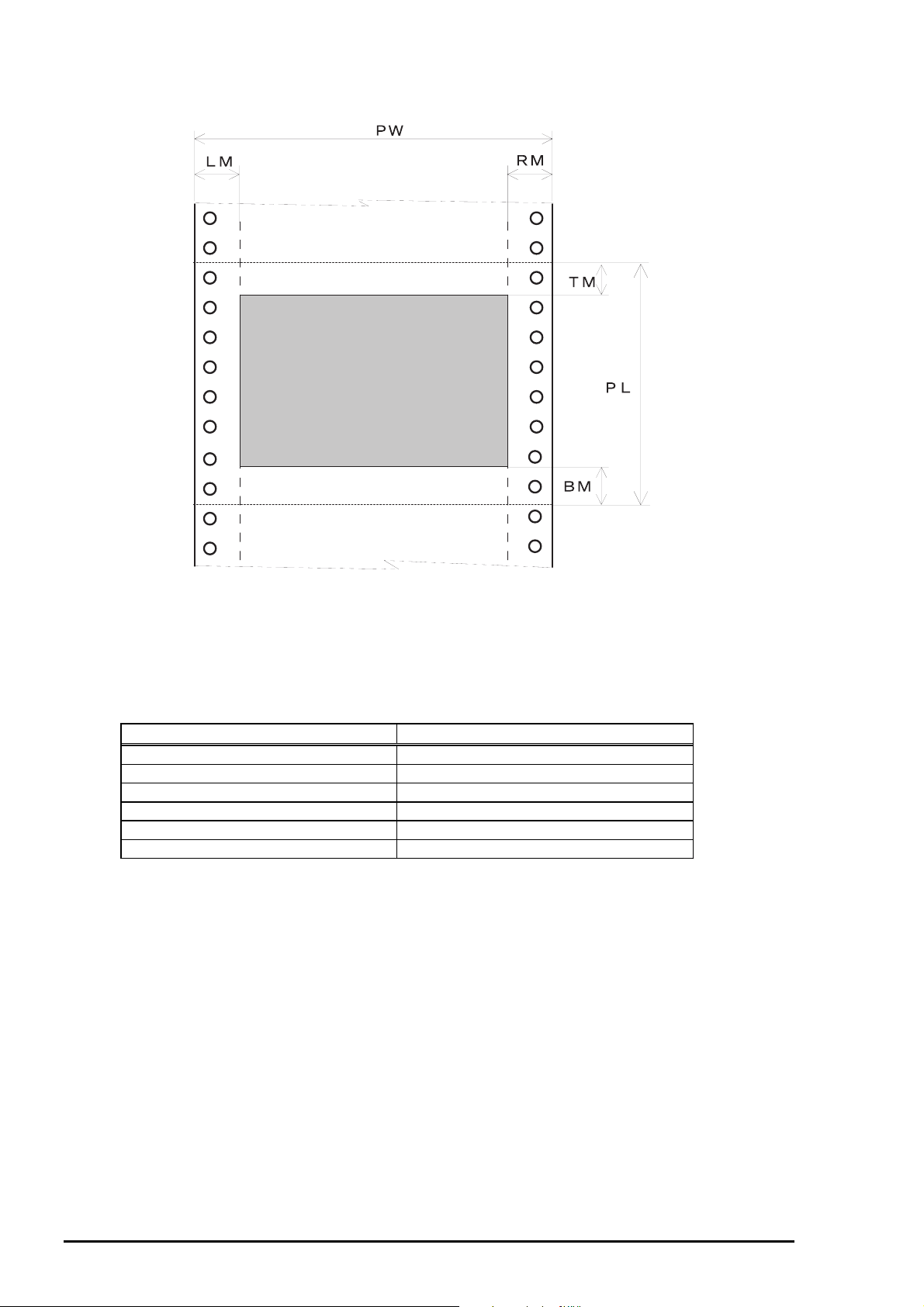
Continuous paper
Perforation
Printable Area
Perforation
Figure 1-7. Printable Area for Continuous Paper
Table 1-16. Printable Area for Continuous Paper
Continuous paper
PW (Width) (Refer to section 1.2.4)
PL (Length) (Refer to section 1.2.4)
LM (Left margin) 13mm or more
RM (Right margin) 13mm or more
TM (Top margin) 4.2mm or more
BM (Bottom margi n) 4.2mm or more
1-1
Rev. A
Page 20
3
Roll paper
Chapter 1 Product Description
PW
LM
BM
Printable Area
Figure 1-8. Printable Area for Roll Paper
TM
BM
Table 1-17. Printable Area for Roll Paper
Continuous paper
PW (Width) (Refer to section 1.2.4)
PL (Length) (Refer to section1.2.4)
LM (Left margin) 3mm or more
RM (Right margin) 3mm or more
TM (Top margin) 0.0mm or more
BM (Bottom margi n) 0.0mm or more
Rev. A
1-1
Page 21

LQ-670 Service Manual
4
1.2.6 Ribbon Cartridge
Type : Fabric
Color : Black
Ribbon life : 2 million characters (LQ 10cpi, 48 dots/character)
Dimensions :120.5mm(W) x 101.5mm(D) x 23.5mm(H)
1.2.7 Input data buffer
0 Kbyte or 64 Kbyte*
Note*)
: Depends on default settings.
1.2.8 Electrical Specification
120V version
Rated voltage : AC120V
Input voltage range : AC103.5 to 132V
Rated frequency range : 50 to 60 Hz
Input frequency range : 49.5 to 60.5 Hz
Rated current : 0.7A(max.2.2A)
Power consumption : Approx.30W (ISO/IEC10561 Letter pattern)
Energy Star Compliant
Insulation resistance : 10 MΩ min.(between AC line and chassis, DC 500V)
Dielectric strength : AC1000 Vrms. 1min.or
AC1200 Vrms. 1 sec.(between AC line and chassis)
230 V version
Rated voltage : AC220 to 240V
Input voltage range : AC198 to 264V
Rated frequency range : 50 to 60Hz
Input frequency range : 49.5 to 60.5Hz
Rated current : 0.4A (max.1.1A)
Power consumption : Approx.30W (ISO/IEC10561 Letter pattern)
Energy Star Compliant
Insulation resistance : 10MΩ min. (between AC line and chassis, DC 500V)
Dielectric strength : AC1500 Vrms. 1min.(between AC line and chassis)
1.2.9 Reliability
Total print volume : 6.5 million lines (except print head)
(MTBF) : 5000 POH
Print head life : 200 million strokes/wire
Ribbon life : 2 million characters
1-1
Rev. A
Page 22

5
1.2.10 Environmental Condition
Temperature
Operating : 5 to 35 °C(without condensation)
: 15 to 25 °C (without condensation and during printing on multi part paper,
envelope, card or label)
Non-operating : −30 to 60 °C
Humidity
Operating : 10 to 80% RH (without condensation)
: 30 to 60% RH (without condensation and during printing on multi part
paper, envelope, card or label)
Non-operating : 0 to 85% RH (without condensation)
Resistance to shock
Operating : 1G, within 1ms
Non-operating : 2G, within 2ms
Resistance to vibration
Operating : 0.25G,10 to 55 Hz
Non-operating : 0.50G,10 to 55 Hz
Chapter 1 Product Description
1.2.11 Safety Approvals
120V version
Safety standards : UL1950 with D3
CSA C22.2 No.950 with D3
EMI : FCC part15 subpart B class B
: CSA C108.8 class B
230V version
Safety standards : EN60950(VDE, NEMKO)
EMI : EN55022(CISPR pub.22) class B
: AS/NZS 3548 class B
1.2.12 CE Marking
230V version
Low Voltage Directive 73/23/EEC : EN60950
EMC Directive 89/336/EEC : EN55022 class B
: EN61000-3-2
: EN61000-3-3
: EN50082-1
: IEC801-2
: IEC801-3
: IEC801-4
1.2.13 Acoustic Noise
Level : Approx. 55 dB(A) (ISO 7779 pattern)
Rev. A
1-1
Page 23

LQ-670 Service Manual
6
1.3 Firmware Specification
This section provides detailed information about LQ-670 firmware.
1.3.1 Control Codes and Fonts
Control codes: :ESC/P 2 and IBM 2390 Plus emulation
Typefaces :Bit map font
EPSON Draft 10CPI, 12CPI, 15CPI
EPSON Roman 10CPI, 12CPI, 15CPI, Proportional
EPSON Sans Serif 10CPI, 12CPI, 15CPI, Proportional
EPSON Courier 10CPI, 12CPI, 15CPI
EPSON Prestige 10CPI, 12CPI
EPSON Script 10CPI
EPSON OCR-B 10CPI
EPSON Orator 10CPI
EPSON Orator-S 10CPI
EPSON Script C Proportional
EPSON Draft(Arabic) 10CPI, 12CPI
EPSON Draft(Hebrew) 10CPI, 12CPI
EPSON Miriam 10CPI, Proportional
EPSON David 10CPI, Proportional
EPSON Naskh 10CPI, Proportional
EPSON Kufi 10CPI, Proportional
:Scalable font
EPSON Roman 10.5pt., 8pt.-32pt.(every 2pt.)
EPSON Sans Serif 10.5pt., 8pt.-32pt.(every 2pt.)
EPSON Roman T 10.5pt., 8pt.-32pt.(every 2pt.)
EPSON Sans Serif H 10.5pt., 8pt.-32pt.(every 2pt.)
:Bar code
Ean-13
EAN-8
Interleaved 2 of 5
UPC-A
UPC-E
Code 39
Code 128
POSTNET
International character sets :14 countries and legal
U.S.A, France, Germany, U.K., Denmark 1, Sweden,
Italy, Spain 1, Japan, Norway, Denmark 2, Spain 2,
Latin America, Korea, Legal
Note)
The international and legal characters are these 12 codes;
23H, 24H, 5BH, 5CH, 5DH. 5EH, 60H, 7BH, 7CH, 7DH, 7EH.
1-1
Rev. A
Page 24
Chapter 1 Product Description
7
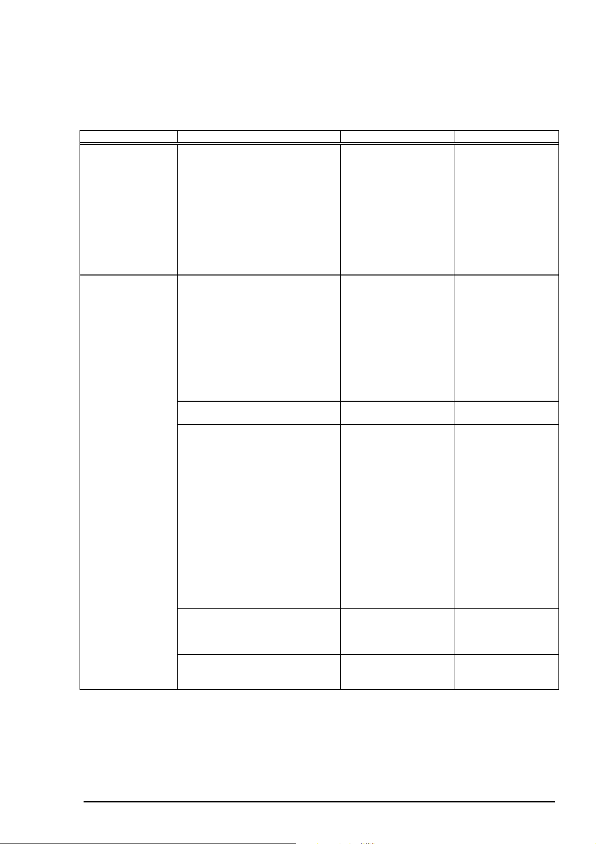
Character tables :The standard version has 11 character tables and the NLSP version has
20 charater tables, as shown in the following table.
Table 1-18. Character Tables
Character table Bitmap font Scalable font
Standard version
NLSP version
Italic table
PC437(US Standard Europe)
PC850(Multilingual)
PC860(Portuguese)
PC861(Icelandic)
PC863(Canadian-French)
PC865(Nordic)
Abicomp
BRASCII
Roman 8
ISO Latin 1
Italic table
PC437(US, Standard Europe)
PC850(Multilingual)
PC860(Portuguese)
PC861(Icelandic)
PC865(Nordic)
EPSON Draft
EPSON Roman
EPSON Sans Serif
EPSON Courier
EPSON Prestige
EPSON Script
EPSON OCR-B
EPSON Orator
EPSON Orator-S
EPSON Script C
EPSON Draft
EPSON Roman
EPSON Sans Serif
EPSON Courier
EPSON Prestige
EPSON Script
EPSON OCR-B
EPSON Orator
EPSON Orator-S
EPSON Script C
EPSON Roman
EPSON Sans Serif
EPSON Roman T
EPSON Sans Serif H
EPSON Roman
EPSON Sans Serif
EPSON Roman T
EPSON Sans Serif H
PC864(Arabic) EPSON Draft
EPSON Roman
PC437 Greek
PC852(East Europe)
PC853(Turkish)
PC855(Cyrillic)
PC857(Turkish)
PC866(Russian)
PC869(Greek)
MAZOWIA(Poland)
Code MJK(CSFR)
ISO 8859-7 (Latin/Greek)
ISO Latin 1T(Turkish)
Bulgaria(Bulgarian)
Estonia(Estonia)
PC744(LST 1283:1993)
ISO 8859-2
PC866 LAT.(Latvian)
PCAPTEC(Arabic)
PC708(Arabic)
PC720(Arabic)
PCAR864(Arabic)
Hebrew7 *1
Hebrew8 *1
PC862(Hebrew) *1
EPSON Draft
EPSON Roman
EPSON Sans Serif
EPSON Courier
EPSON Prestige
EPSON Script
EPSON Draft(Arabic)
EPSON Naskh
EPSON Kufi
EPSON Draft(Hebrew)
EPSON Miriam
EPSON David
(Not supported)
(Not supported)
(Not supported)
(Not supported)
Note *1) These fonts are not selected in the default setting mode.
Note)
Rev. A
ESC R command is effective on the character tables with bold weight.
1-1
Page 25
LQ-670 Service Manual
8
1.3.2 Interface Specification
This printer provides bi-directional 8-bit parallel interface and Type-B optional interface slot as standard.
1.3.2.1 Parallel interface (Forward channel)
[Transmission mode]
[Adaptable connector]
[Synchronization]
[Handshaking]
[Signal level]
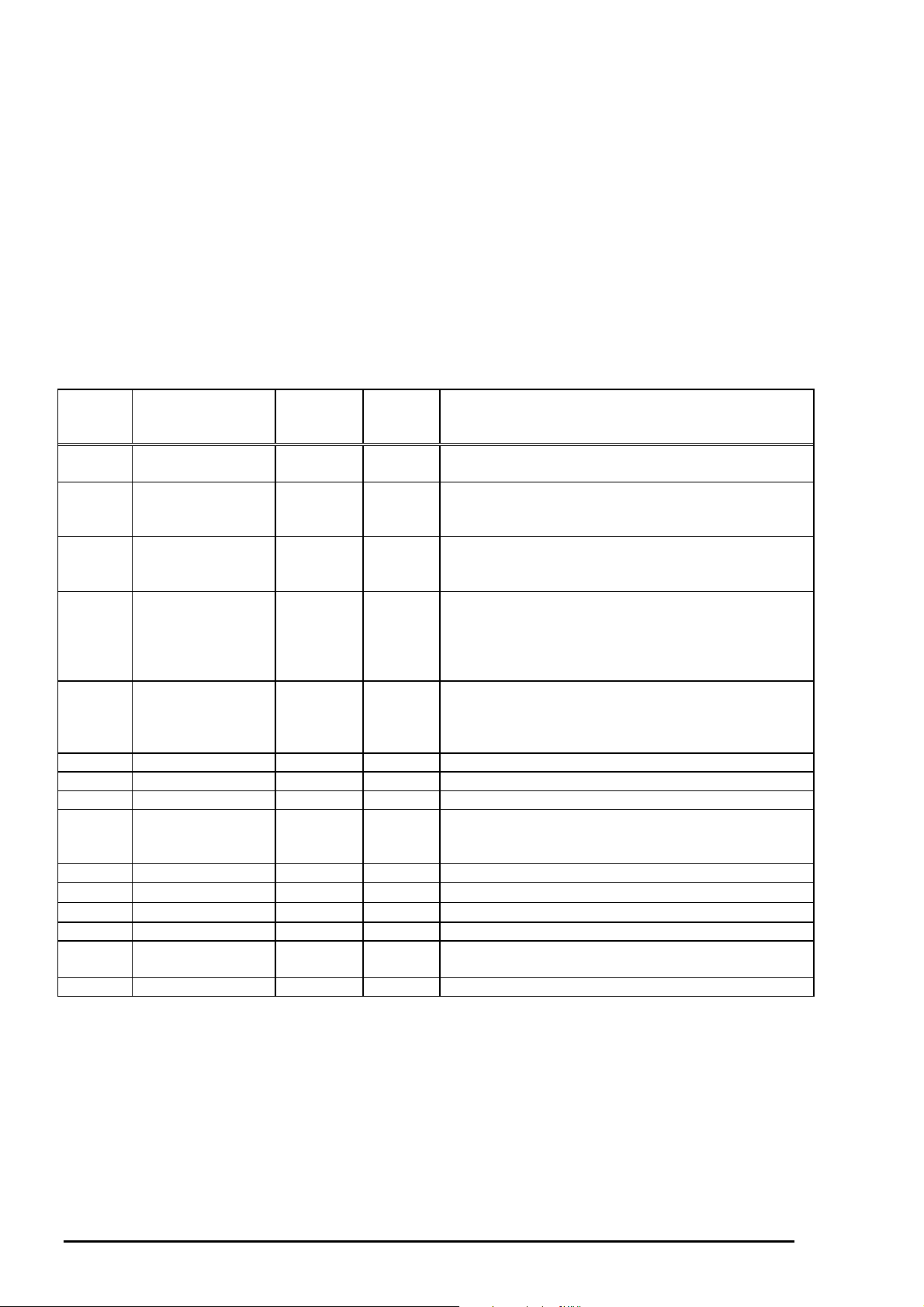
Table 1-19. Connector Pin Assignment and Signals
Pin No. Signal Name Return
1 /STROBE 19 In Stroke pulse. Input data is latched at falling edge of
2∼9DATA1∼820∼27
10 /ACKNLG 28 Out This signal (negative pulse) indicates that the printer
11 BUSY 29 Out This signal’s “HIGH” level indicates that the printer
12 PE 28 Out This signal’s “HIGH” level indicates that the printer
13 SLCT 28 Out Always at high level when the printer is powered on.
14 /AFXT 30 In Not used.
31 /INIT 30 In This signal’s negative pulse initializes printer.
32 /ERROR 29 Out This signal’s low level means the printer is in a state
36 /SLIN 30 In Not used.
18 Logic H ---- Out
35 +5V --- Out
17 Chassis --- --- Chassis GND.
16,33
19-30
15,34 NC --- --- Not connected.
GND --- --- Signal GND.
: 8 bit parallel, IEEE-1284 compatibility mode
: 57-30360 (Amphenol) or equivalent
: /STROBE pulse
: BUSY and /ACKNLG signals
: TTL compatible (IEEE-1284 level 1 device)
In/Out * Function description
GND
Pin
the signal.
In Each signal represents information of parallel data
from 1 bit to 8 bit. The data is 1 at “HIGH” and is 0
at “LOW”.
has received data and is ready to accept next one.
The pulse width is 5µs.
is not ready to accept data. On the other hand,
“LOW” means the printer can take data.
(Refer to the next page for conditions when this
signal becomes high level)
is in a state of paper-out error.(Refer to the next
page for the condition when this signal becomes
high level.)
of error. (Refer to the next page for conditions when
the signal becomes low level)
This line is pulled up to +5V through 3.9 kΩ resistor.
This line is pulled up to +5V through 1.0 kΩ resistor.
Note)
*In/Out shows the direction of signal flow from the printer's point of view.
Note)
If the signal is “LOW” and active state, the signal is marked with “/”.
1-1
Rev. A
Page 26
Chapter 1 Product Description
9
BUSY signal is active (high level) under the following conditions.
In the process of receiving data.
In the condition of being input buffer full
In the condition of being /INIT signal active(low level)
During hardware initialization
In the condition of being /ERROR or PE signal active(low level, high level, respectively)
In the self test mode
In the adjustment mode
In the default-setting mode
/ERROR signal is active(low level) under the following conditions.
In the condition of the release lever error
In the condition of the paper-out error
In the condition of the paper-jam error
PE signal is active(high level) under the following condition.
In the condition of paper-out error
Note)
It becomes possible to input the data without outside equipment by setting appropriate connecting.
Note)
Rev. A
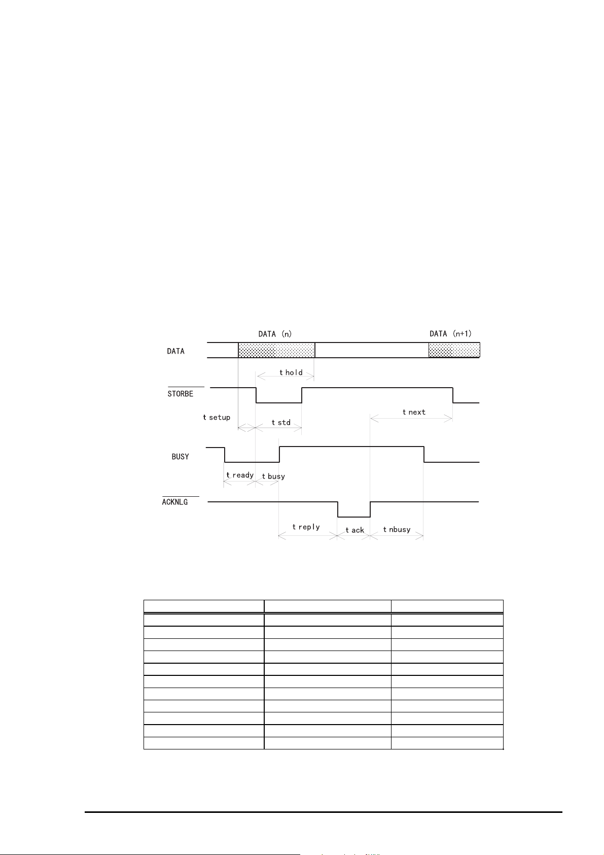
Figure 1-9. Data Transmission Timing
Table 1-20. Maximum and Minimum Timings for Data Transmission
Parameter Minimum Maximum
tsetup 500 nsec ---
thold 500 nsec ---
tstb 500 nsec ---
tready 0 ---
tbusy --- 500 nsec
treply --- ---
tack 500 nsec 10 us
tnbusyt 0 ---
tnext 0 ---
ttout* --- 120 nsec
ttin** --- 200 nsec
* Rise and fall time of output signals.
** Rise and fall time of input signals.
1-1
Page 27
LQ-670 Service Manual
0
1.3.2.2 Parallel Interface (Reverse channel)
[Transmission mode]
[Adaptable connector]
[Synchronization]
[Handshaking]
[Signal Level]
[Data transmission timing]
[Extensibility request]
when the request is 00H or 04H, which mean;
[Device ID]
Table 1-21. Connector Pin Assignment and Signals
Pin
No.
1 HostClk 19 In Host clock signal
2∼9DATA1∼820∼27
10 PtrClk 28 Out Printer clock signal.
11 PtrBusy, DataBit-3,7 29 Out Printer busy signal and reverse channel
12 AckDataReq, DataBit-2, 6 28 Out Ack nowledge data request signal and reverse
13 Xflag, DataBit-1, 5 28 Out X-flag signal and reverse channel trans f er data
14 HostBusy 30 In Host busy signal.
31 /INIT 30 In Not used.
32 /Data Av ail, DataBit-0, 4 29 Out Data available signal and reverse channel
36 1284-Active 30 In 1284 active signal.
18 Logic-H --- Out A high signal indicates that all other signals
35 +5V --- Out
17 Ch assis --- --- Chassis GND.
16,33,
19-30
15,34 NC --- --- Not connected.
GND --- --- Signal GND.
Signal Name Return
: IEEE 1284 nibble mode
: 57-30360(Amphenol) or equivalent
: /STROBE pulse
: BUSY and /ACKNLG signals
: IEEE-1284 level 1 device
TTL compatible
: Refer to the IEEE-1284 specification
: The printer responds to the extensibility request in the affirmative,
00H:Request nibble mode of reverse channel transfer
04H:Request device ID in nibble mode of reverse channel
transfer.
: [00H] [3AH]
MFG: EPSON;
CMD:ESCPL2,PRPXL24, BDC;
MDL;LQ-670;
CLS:PRINTER;
In/Out* Function description
GND
Pin
In Parallel input data to the printer.
transfer data bit 3 or 7.
channel transfer data bit 2 or 6.
bit1 or 5.
transfer data bit0 or 4.
sourced by the peripheral are in a valid state.
This line is pulled up to +5V through 1.0 kΩ
resistor.
Note*):
1-2
In/Out refers to the direction of signal flow/from the printer’s point of view.
Rev. A
Page 28

Chapter 1 Product Description
1.3.2.3 Optional Interface
Type-B optional interface cards are available.
Table 1-22. Optional Interface
Reply message ESC/P2 IBM 2390 Plus
Main-Type MT24p,PW106cl10cpi,PRG(W0xxxx)rev MT24p,PW106c110cpi,PRG(W0xxxx)rev
Product-Name LQ-670 LQ-670
Emulation-Type ESCPL2-00 PRPXL24-01
Entity-Type EPSONLQ2 EPSONPRPXL24
1.3.2.4 Interface Selection
The printer has 2 interfaces; the parallel interface and Type B optional interface. These interfaces are
selected manually by Default setting or selected automatically.
1.3.2.5 Manual selection
Out of 2 interfaces can be selected by Default Setting.
1.3.2.6 Automatic selection
The automatic interface selection is enabled by Default Setting. In this automatic interface selection
mode, the printer is initialized to the idle state scanning which interface receives data when it is powered
on. Then the interface that receives data first is selected. When the host stops data transfer and the
printer is in stand-by state for the seconds specified by Default Setting, the printer is returned to the idle
state. As long as the host sends data or the printer interface is bus y state, the selected inter f ace is let as it
is.
1.3.2.7 Interface state and interface selection
When the parallel interface is not selected, the interface gets into a busy state. When the Type-B serial
interface card is installed and it is not s elec ted, the inter f ace s ends X OFF and s ets the DT R s ignal MARK.
When the optional interface is not selected, the printer sends disable commands to the optional interface.
When the printer is initialized or returned to the idle state, the parallel interface gets into a ready state, the
serial interface sends XON and sets the DTR SPACE and the printer sends enable commands to the
optional interface. Caution that the interrupt signal such as a /INIT signal on the parallel interface is not
effective while that interface is not selected.
1.3.3 Prevention Hosts from Data Transfer Timeout
Generally, hosts abandons data transfer to peripherals when a peripheral is in busy state for dozens of
seconds continuously. To prevent hosts from this kind of timeout, the printer receives data very slowly,
several bytes per minute, even if the printer is in busy state. This slowdown is started when the rest of the
input buffer becomes s everal hundreds of bytes. At last, when the input buffer is full, the printer is in busy
state continuously.
Rev. A
1-21
Page 29
LQ-670 Service Manual
2
1.4 Operation
1.4.1 Control Panel
There are 7 switches and 8 LEDs on the panel as shown below.
Operate
Micro Adjust
LF/FF
Draft
Roman
Sans Serif
Courier
Prestige
Script
Others
Font
Condensed
Paper Out
Pause
Figure 1-10. Control Panel
3sec
Load/Eject
Tear Off/Bin
Tear Off
Bin 1
Bin 2
Card
LED Off
LED On
LED Blinks
1.4.1.1 Usual Operation
Operate
This switch turns the printer on and off. It is the secondary switch.
Pause
This switch alternates printer activity between printing and non-printing.
Holding it down over 3 seconds when the printer is in the stand by state, the Micro Adjust function
is enabled. Pressing it again, this function is disabled.
Load/Eject
Pressing it loads cut sheet or continuous paper when the printer is out of paper.
Pressing it ejects cut sheet to the stacker or continuous paper to the paper park.
LF/FF
Pressing it shortly executes line feed.
Holding it down for a few seconds executes form feed when continuous paper is used, or ejects cut
sheet to the stacker when cut sheet is used.
Tear Off
When continuous paper is used, pressing it moves a page to the Tear-off position. And pressing it
again moves a next page to the TOF position.
1-2
Rev. A
Page 30

Chapter 1 Product Description
3
Bin
Pressing it selects CSF bin number or the Card mode* when cut sheet is used.
Note*)
Card mode is for using post card or envelope.
Font
Pressing it selects one of following fonts.
Draft, Roman, Sans serif, Courier, Prestige, Script and Others *.
Note*)
Others means the font selected in the Default Setting Mode.
Condensed
Pressing it alternates condensed and non-condensed mode.
Micro Adjust
Micro Adjust ↑/↓ switches is effective when the Micro Adjust function is enabled by Pause switch.
Pressing the Micro Adjust ↑/↓ switches execute micro feed backward and forward by 1/80 inch.
The TOF adjustment is enabled in the TOF position after loading, and the Tear-off adjustment is
enabled in the Tear-off position.
Rev. A
1-2
Page 31

LQ-670 Service Manual
4
1.4.1.2 Switches
Operation in normal mode
In normal mode, pressing panel switches executes following function.
Table 1-23. Operation in Normal Mode
Switch Function
Operate Turn the printer on and off.
Pause Alternates printing and no-printing status.
Enables Micro Adjust function, holding it down for 3 seconds.
Load/Eject Loads or ejects the paper.
Executes micro feed forward, when this function is enabled.
LF/FF Executes line feed, pressing it shortly.
Executes form feed, holding it down for a few seconds.
Executes micro feed backward, when this function is enabled.
Tear Off/Bin Advances continuos paper to the Tear-off position.
Selects CSF bin ½ or Card mode.
Font Selects font.
Condensed Alternates condensed mode and non-condensed mode.
Operation at power on
Turning the printer on while pressing panel switches executes the function shown below.
Table 1-24. Operation in Power On
Switch Function
Load/Eject LQ self test
LF/FF Draft self test
Font Default setting
Load/Eject & LF/FF Data dump
Condensed &Tear Off/Bin Clear EEPROM
Pause Bi-d adjustment
Font & Condensed Quiet mode
The others Not available
Operation in default setting mode
The switches are used in default setting mode as follows:
Table 1-25. Operation at Default Setting Mode
Switch Function
Font Selects the Menu
Tear Off/ Bin Changes the setting
The others Not available
1-2
Rev. A
Page 32

5
1.4.1.3 Indicators(LED)
This printer displays present conditions and errors on the indicators.
Indication in normal mode
Table 1-26. LED Indicators
Chapter 1 Product Description
LED
Printer Status
Pause On --- --- --- ---
Paper out error On On --- --- --Paper jam
error
Paper eject
error
Head hot Blink --- --- --- --Micro Adjust Blink --- --- --- --Tear off --- --- *3 --- --Bin selection --- --- *3 --- --Condensed --- --- --- On --Font selection --- --- --- --- *4
Fatal error Blink Blink Blink Blink Blink
*1 Pause (Orange)
It is on when the printer is paused, and it is off when the printer is not paused.
It blinks when the Micro Adjust function is enabled or the printer is in the head hot status.
*2 Paper Out (Red)
It is on when the printer is in the paper out status, and it is off when the printer is out of this status.
*3Tear Off/Bin (Green)
2 LEDs display the status of CSF bin selection when cut sheet is used. Only a right LED is on when
Bin1 is selected, only a left LED is on when Bin2 is selected, and both LEDs are on when the Card
mode is selected.
Both LEDs blinks when continuous paper is in the Tear-off position and both LEDs are off when
continuous paper is out of the Tear-off position.
Pause
*1
On Blink --- --- --On Blink --- --- ---
Paper Out
*2
Tear Off/Bin Condensed Font
*4Font (Green)
The status of Font selection is displayed by 3 Font LEDs.
Rev. A
1-2
Page 33

LQ-670 Service Manual
6
1.4.1.4 Buzzer
When the printer detects errors, it displays errors on the LEDs and also the buzzer beeps as warning
sign.
Table 1-27. Buzzer
Warning sign Beeper sounds
Paper out error
Paper jam error
Paper eject error
Release lever operation error
Illegal panel operation
❍ ❍ ❍
● ● ● ● ●
❍ ❍ ❍
● ● ● ● ●
❍
Note
❍ : Beeper sounds approx. 100ms and interval is approx.100ms.
)
● : Beeper sounds approx. 500ms and interval is approx.100ms.
1-2
Rev. A
Page 34

Chapter 1 Product Description
7
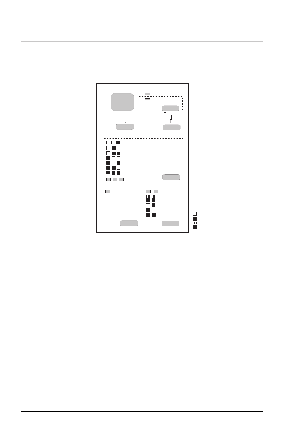
1.4.2 Default Setting
Setting Method
Several printer settings loaded at each power-on can be changed in this operation. The method is
described in the guidance sheets (language selection sheet and printer setting sheet) which are
printed out at first in the setting mode if desired.
User is requested to operate 2 switches watching 6 LEDs on the control panel. The lights turn on and
off, and blink in one of the patterns described in the guidance sheets.
This setting mode uses the menus of 3 types as follows;
Language menu: : List of the languages to be used for the printer setting sheet
Main menu : List of items to be set(ex. “CG table”, “Auto line feed”)
Submenus : Lists of value/setting of the each item(ex. “PC437”, “ON”)
1) Language selection sheet is printed out. The s heet describes how to select a language among the
five; English, French, German, Italian and Spanish in all languages.
2) Font LEDs indicate the top item on “Language menu”.
3) The selection can be changed with Font switch.
4) When Tear off/Bin switch is pressed, the setting sheet is printed out in the language.
5) Font LEDs indicate the top item on “main menu”.
6) The selection can be changed with Font switch.
7) W hen Tear off/Bin switch is pressed, printer changes the indication to the “s ubmenu” of the selected
item.
8) Condensed & Tear off/Bin LEDs indicate the current setting/value on the submenu.
9) The setting/value can be changed with Tear off/Bin switch.
10) When Tear off/Bin switch is pressed, printer memorizes the last setting/value, and changes its
indication to the main menu.(Back to (5)).
11) The other items can be changed in the same manner.
Setting Mode (Factory setting)
Table 1-28. Setting Menu
Item Setting/Value
Character table Standard version:
PC 437
Italic,
Abicomp, ISO Latin1, Roman8
NLSP version:
PC437
Italic,
PC864, PC866, PC869, ISO Latin 1T, ISO8859-7 MAZOWIA, Code
MJK, Bulgaria, Estonia, PC774, ISO 8859-2, PC866LAT.
PCAPTEC*5, PC708*5, PC720*5, PCAR864*5, PC860*5, PC861*5,
PC865*5
International character set for
Italic table *4
Font *1
Page Length for tractor
High speed draft
Print Direction
Software
I/f mode
Auto I/F wait time
Input buffer
Skip over perforation
Auto tear off
Auto line feed
Auto CR (IBM 2390 Plus)*2
A.G.M (IBM 2390 Plus)*2
0 slash
Buzzer
* Refer to the next page for
Notes.
Italic U.S.A
Italic Sweden, Italic Italy, Italic Spain
OCR-B, Orator, Orator-S, Script C,
3 inch, 3.5 inch, 4 inch, 5.5 inch, 6 inch, 7 inch, 8 inch, 8.5 inch,
inch
, 70/6 inch, 12 inch, 14 inch, 17 inch
On
, Off
Bi-d
Auto,
ESC/P2
Auto,
10sec
On
On,
On,
On,
On,
On,
On,
On
, IBM2390 Plus
Parallel I/F, Option I/F
., 30sec.
, off
Off,
Others
Off
Off
Off
Off
Off
, Off
, PC850, PC860, PC863, PC865, PC861, BRASCII,
, PC437 Greek, PC850, PC852, PC853, PC855, PC857,
, Italic France, Italic Germany, Italic U.K., Italic Denmark,
Roman T
, Uni-d
, Sans serif H
11
Rev. A
1-2
Page 35

LQ-670 Service Manual
8
Note*1):
Note*2)
Note*3
Note*4
Note*5):
1.
Bi-d adjustment can be adjusted by users. By using this mode, the gap of lines; line for right printing
direction and line for left printing direction can be adjusted. The setting value is stored in the EEPROM of
the main control board and retained even after the power is turned off. Bi-d adjustment method is as
follows.
1) Turning the printer on while pressing Pause switch.
2) Select most closely aligned number by pressing LF/FF(↓) and Load/Eject(↑) switches.
is also changed by according to the selection.
3) Fix the selected number by pressing Font switch.
4) Repeat 2)-3) until finishing Bi-d. adjustment for LQ mode.
5) Turn the printer off.
One of these fonts selected in the default setting is corresponding to others(=other fonts) on
the control panel. Following fonts are not selected in the default setting mode.
Draft, Roman, Sans serif, Courier, Prestige and Script
: These settings are effective when IBM 2390 Plus emulation is selected.
): Settings with bold weight mean the standard factory settings.
): “Italic Denmark” is as same as “Italic Denmark 1”, and “Italic Spain” is as same as “Italic Spain
1”.
Hebrew7, Hebrew8, PC862 are not selected in the default setting mode.
4.3
Bi-d Adjustment
The guide to adjust Bi-d alignment in this mode is printed and first alignment pattern is printed.
Font LEDs show the pattern number which is selected at that time. The selection is advanced
one by one as the switch is pressed, and the combination of On/Off/ Blink of those three LEDs
Selected number is fixed and next alignment pattern is printed.
Following adjustment is executed.
1. Bi-d adjustment for draft mode
2. Bi-d adjustment for draft copy mode
3. Bi-d adjustment for LQ mode
Note)
The setting values are stored into non-volatile memory and retained even if EEPROM is reset.
1-2
Rev. A
Page 36

Chapter 1 Product Description
9
1.4.4 Initialization
Power-On initialization
The initialization of this level is activated by power-on or cold reset command(remote RS command).
This initialization is;
to initialize the printer mechanism.
to execute Operator initialization.
Operator Initialization
The initialization of this level is activated by /INIT signal(negative pulse). This initialization is;
to clear the all buffers of data.
to cancel the download character definition.
to make the printer stand-by state, if no errors occur.
to execute Software initialization.
Software Initialization
The initialization of this level is activated by the control code ESC @. This initialization is;
to clear the unprinted data.
to make the printer’s setting defaults.
1.4.5 Errors
This printer goes to the error s tate when the following condition is detected, and changes ERROR signal
to ”LOW” and “BUSY” signal to “HIGH” , and stops taking data. Also, the printer goes unprintable condition
automatically.
Fatal errors is detected.
Paper out error or paper jam error is detected.
Paper eject error is detected.
When the present paper path and the position of release lever do not match. (Release lever
operation error)
Fatal errors
Carriage control error, Power supply voltage error and CG access error.
Paper out error
When printer fails to load a sheet, it goes paper out error.
Paper eject error
When printer fails to eject a sheet, it goes paper eject error.
Paper jam error
When printer fails to feed a sheet, it goes paper jam error.
Rev. A
1-2
Page 37

LQ-670 Service Manual
0
1.5 Main Components
This printer consists of the following components.
C214MAIN Board
C214 PSB/PSE Board
C214 PNL Board
Printer Mechanism(M-5060)
Housing
1.5.1 C214 Main Board
This main board consists of 16bitCPU TMP96C041AF (IC11) which is driven by 17.20MHz clock drive
frequency, Gate array E05B42(IC10), 2/4M Flash-EPROM(IC7), or 8M PROM(IC8), 4/8/32M MROM (IC4)
for CG, 8M PROM (IC5), 1MPSRAM (IC6), EEPROM 93C46(IC9), Reset IC RST592D (C12), PF Motor
drive circuit, CR motor drive circuit and print head drive circuit.
Gate Array(IC10)
PROM(IC8)
Reset IC(IC12)
PROM(IC5)
EEPROM(IC9)
PSRAM(IC5)
Flash-EPROM(IC7)
CPU(IC11)
Print Head Driver
PF Motor Driver IC
CR Motor Driver IC
Figure 1-11. C214 Main Board
1.5.2 C214PSB Board
This board consists of fuse, filter circuit, primary side diode bridge, switching FET, transformer and
chopper IC for +5V generation. Also, the secondary switch is used for power and is operated by On/Off of
the power switch on the operation panel of the printer.
Fuse
Filter Circuit
SwitchingFET
Chopper IC for +5V generation
Diode Bridge
Transformaer
Figure 1-12. C214 PSB Board
1-3
Rev. A
Page 38

Chapter 1 Product Description
1.5.3 C214 PNL Board
This panel board consists of one switch as power switch, 6 non lock type switches and 8 LEDs.
1.5.4 Printer Mechanism
This unit consists of carriage mechanism, paper feed mechanism, cut sheet/transformer change over
mechanism, platen gap adjustment mechanism and print head.
1.5.5 Housing
The housing of this printer consists of upper housing, printer cover, front sheet guide, rear sheet guide and
lower housing.
Rev. A
1-31
Page 39

Chapter 2
Operating Principles
2.1 Printer Mechanism Operation..............................................................................2-1
2.1.1 Printing Mechanism ............................................................................................................... 2-1
2.1.2 Carriage Mechanism .............................................................................................................. 2-3
2.1.3 Ribbon Advance Mechanism................................................................................................. 2-5
2.1.4 Paper Advance Mechanism...................................................................................................2-6
2.1.4.1 Paper Advance Mechanism ...................................................................................... 2-6
2.1.4.2 Paper Advance Detector Mechanism........................................................................ 2-7
2.1.4.3 Release Lever Mechanism........................................................................................ 2-9
2.1.5 Platen Gap Adjustment........................................................................................................ 2-10
2.2 Power Supply Operation....................................................................................2-11
2.2.1 Power Supply Circuit ........................................................................................................... 2-11
2.2.1.1 Power Supply Overview............................................................................................2-11
2.2.1.2 Power Supply Circuit Operation .............................................................................. 2-12
2.2.2 Control Circuit ......................................................................................................................2-13
2.2.2.1 Operating Principles of the Control Circuit ..............................................................2-13
2.2.2.2 EEPROM Control Circuit......................................................................................... 2-14
2.2.2.3 System Reset Circuit............................................................................................... 2-14
2.2.2.4 Power Off Detector Circuit....................................................................................... 2-15
2.2.2.5 Print Head Driver Circuit..........................................................................................2-15
2.2.2.6 CR Motor Driver Circuit ........................................................................................... 2-16
2.2.2.7 PF Motor Driver Circuit............................................................................................ 2-16
2.2.2.8 Operation Panel Control Circuit...............................................................................2-17
2.2.2.9 Interface(I/F) Circuit................................................................................................. 2-18
2.2.2.10 Head Temperature Detector Circuit.......................................................................2-18
2.2.2.11 Head Drive Voltage Measurement Circuit ............................................................. 2-18
2.2.2.12 Rear and Front Paper End Detector Circuit .......................................................... 2-18
2.2.2.13 Paper Width Detector Circuit................................................................................. 2-18
2.2.2.14 Carriage Home Position (HP) Detector Circuit...................................................... 2-18
2.2.2.15 Release Lever Detector Circuit ............................................................................. 2-18
2.2.2.16 Adjust Lever Detector Circuit................................................................................. 2-18
Page 40

LQ-670 Service Manual
2.1 Printer Mechanism Operation
This section describes the printer mechanism(M-5060) and explains how it works.
2.1.1 Printing Mechanism
The printing mechanism of this printer is composed of head, ink ribbon and ribbon mask.
The print head is an 24-pin(12pins X 2) head for impact dot printing.(Refer to Chapter 1)
Each wire has its own drive coil.
Actuating Plate
Actuating Spring
Head Driving Coil
Iron Core
Paper
Figure 2-1.Print Head Operation Principles
1. A drive signal, transmitted from the control circuit to the prinhead drive circuit, is converted to the
proper printhead driving voltage, which energizes a corresponding coil. The energized coil then
causes the iron core to become magnetized.
2. The magnetic force draws the actuating plate toward the core, and the dot wire, which is connected
to the core, rushes toward the platen.
3. When the dot wire impacts the platen, pressing against the ribbon and paper, it prints a dot.
4. When the driving voltage stops energizing the coil, the magnetic force vanishes from the iron core. The
actuating plate returns to its original position (the position before coil was energized) with spring action.
The dot wire also returns to its original position.
The mechanism is equipped with a built-in thermistor for head temperature detection. The temperature
detected by the thermistor is converted to an electric signal and fed back to the control circuit. In order to
keep the same print quality, the drive mode of the print head is changed over according to the paper type
and head temperature. This drive mode minimizes the degradation or damage to the dot wires in the print
head, which is caused by temperature rise of the print head from continuous printing, and also keeps print
quality when the surrounding temperature is extremely low. (Refer to section 1.2.2 for the changes of print
speed by the temperature of the head)
The next page shows print head specification.
Stopper
Wire Resetting Spring
Wire
Ink Ribbon
Ribbon Mask
Platen
Rev. A
2-1
Page 41

Chapter 2 Operating Principles
2
Category Specification
Print Method Impact dot matrix
Number of pin wires 24-pin (12X2)
Wire diameter 0.20mm
Print head life 200 million strokes/wire
Weight
Coil direct current resistance
Response Frequency Normal Mode : 1500Hz
Drive Voltage
Drive Condition
Environmental condition
Print drive method Constant voltage drive method
Table 2-1. Print Head Specification
115 ± 12g
39.3 ± 2.7 Ω (at 25 °C)
Buzzer : 1.5KHz
42 ± 3V
• Normal Drive
• Thick paper (using multipart or thick papers)
• Buzzer function
Temperature : 5∼55 °C
Humidity : 10∼85%
2-
Rev. A
Page 42

LQ-670 Service Manual
3
2.1.2 Carriage Mechanism
Carriage Mechanism consists of the carriage movement mechanism and platen gap adjustment
mechanism.
Carriage Movement Mechanism
The figure below shows carriage mechanism. The top of the carriage is supported by the CR guide
frame, and down side is by the CR guide shaft. Since the carriage motor is stepping motor, the
carriage moves freely, and the rotation of the motor is conveyed to the timing belt pulley and drive the
timing belt.
A part of the timing belt is attached to the head carriage, which is moved right and left on the carriage
guide shaft by the rotation of the carriage motor. The timing belt is pre-pressed by the spring and
adjust the elastic motion of the belt which is caused by temperature changes, and keep a certain
belt strength and tension.
The carriage home position detector uses photo coupler method and is located on the right edge of
the mechanism. The detector is detected when the carriage flag interrupts the light emitted from the
photo coupler. The carriage home position control performs open loop control after the HP detector
detects standard position. After the location is determined for the carriage to move by the printing
data, the control circuit calculates the pulse of the motor phase corresponding to the distance to move,
and outputs that information to the motor. Therefore, the detection of mis-location is detected when
the home signal is detected during printing or initialization and the printer goes to the error state.
Also, the moving speed of the carriage is controlled by carriage motor drive frequency according to the
printing data.
CR Motor
Timing Belt
Carriage
CR Guide Frame
Flag
Figure 2-2. Carriage Mechanism
Spring
CR Home Position
Detector
CR Guide Shaft
Table 2-2. Specification of the Carriage HP Detector
Category Specification
Method Photoelectric transfer method
Voltage
Switch Mode Open : In the detector range
Rev. A
5VDC ± 5%
Close : Out of the detector range
2-
Page 43

Chapter 2 Operating Principles
4
Category Specification
Type 200-pole, HB-type Stepping motor
Coil Resistance
Drive Voltage
Drive Resolution 0.106mm/step (1-2 phase)
Drive Method Constant current drive
Current Consumption Rated speed : 0.68A/phase
Drive Frequency
Table 2-3. CR Motor Specification
3.5Ω ± 10%
42V±5%
1-2 phase, W1-2 phase
At the waiting mode : 0.2A/phase
667∼7200Hz
2-
Rev. A
Page 44

LQ-670 Service Manual
5
2.1.3 Ribbon Advance Mechanism
The ribbon advance mechanism consists of the rack mounted on the carriage guide frame, the pinion
mounted on the carriage unit, planetary gear, combination gear and ratchet RD. When the carriage unit is
moved right and left on the carriage guide shaft by the CR motor, the pinion is rotated by the rack and the
motive power is conveyed to the planetary gear . When the carriage unit moves to left, the pinion is rotated
by the rack, and the motive force is conveyed to the planetary gear. Also, when the carriage unit moves to
the right side, the driving force from the planetary gear is once conveyed into the combination gear, and
the combination gear drives the ratchet RD. Then the ratchet RD rolls up the ribbon.
Ribbon Cartridge
Ink Ribbon
Carriage Unit
Combination Gear
Planetary Gear
Carriage Guide Frame
Pinion
Ratchet RD
Ribbon Advance Roller
Figure 2-3. Ribbon Advance Mechanism
Rev. A
2-
Page 45

Chapter 2 Operating Principles
6
2.1.4 Paper Advance Mechanism
The paper feed mechanism of this printer consists of the platen roller, paper feed roller, paper eject roller,
PF motor, tractor unit, PW detector, PE (rear/front) detectors, release detector, and CSF
mechanism(option). This printer performs paper advance by moving the paper horizontally.
Mechanism Frame
Roller Assembly, PF,Support
Paper Bail Roller
Roller Assembly, Paper
Eject, Drive
Roller PF Drive
Platen Roller
PF Motor
Tractor Transmission
Gear
To CSF Mechanism
Tractor Gear
Figure 2-4. Paper Advance Mechanism
2.1.4.1 Paper Advance Mechanism
Driving force of the PF motor is conveyed through the paper feed gears to roller assembly, paper eject
drive, paper bail roller, platen roller, roller assembly, PF support and roller, PF drive, and advances paper.
The driving force conveyed to the tractor gear is sent to the CSF drive gear in case the CSF is mounted.
Also, the tractor transmission gear conveys driving force to the tractor gear by the release mechanism and
enables the push tractor to feed the paper.
Friction Advance Mechanism
The paper is held between paper eject and the roller assemblies located under the carriage guide
shaft (2 for each up and down; total 4)
Paper Load : Front automatic feed (manual feed), paper load from the CSF
Paper Eject : Front paper eject
Push tractor Mechanism
By changing the release lever from the cut sheets position to the continuous paper position manually,
the mode is changed from friction mode to tractor mode. In the tractor mode, the driving force for
paper load is conveyed to the tractor side, and the contact to the roller is lost by the release
mechanism.
Paper Load : Tractor
Paper Eject : Front paper eject
Table 2-4. Paper Advance Specification
Category Specification
Type 2-phase 96 poles Hybrid type Stepping Motor
Coil Resistance
Drive Voltage
16.0Ω ± 10% (at 25 °C, per phase)
42V ± 5%
Drive Method Bi-pola constant current drive
1-2, 2-2 phase, W1-2 phase,
Micro paper sending 1/360 inch(1-2 phase)
Drive Frequency
600∼7000Hz
Rated Current 0.535A (constant speed)
2-
Rev. A
Page 46

LQ-670 Service Manual
7
2.1.4.2 Paper Advance Detector Mechanism
Paper advance detector mechanism consists of PW detector and PE (rear/front) detectors.
The function of this mechanism is to feedback information about monitoring paper edges, paper width and
paper jam, and to control paper advance. The detector’s reading operation is constantly performed. The
timing to feedback the red signals is necessarily selected by CPU according to the operation of PF motor
and CR motor. The table below shows specification of the detectors and their functions.
CR Motor
Platen
Print Head
Print Head
Rear PE Detector
Roller Assembly, PF, Support
Roller Assembly, Paper Eject,
Drive
TOP Detector
Mask Guide
Looking from
the front face.
Looking from
the top.
TOP Detector
Front PE Detector
Mask Guide
Figure 2-5. Paper Advance Detector Mechanism
Table 2-5. Detector Function and Operation
Detectors Operation Function
PW detector Paper width measurement (detects
Determines right and left margin
right and left edges)
Paper top edge detector(detects
Determines top and bottom margin
top and bottom edges)
Detects if there is any paper or not Detects paper jam after checking
paper loading and ejecting.
PE detectors (Rear/Front) Detects top and bottom margin Determines top and bottom margin
Detects if there is any paper or not Detects paper jam and paper out (if
PW detector does not detect the
paper out) after checking paper
loading and ejecting.
Front paper detector only Detects paper top margin Front entry in case of cut sheet
auto feed
Rev. A
2-
Page 47

Chapter 2 Operating Principles
8
Category Specification
Type Mechanism type
Switch Rating
Switch Mode Paper in : Open
Category Specification
Type Mechanism type
Switch Rating
Switch Mode Paper in : Open
Category Specification
Type Photoelectric transfer method
Voltage
Switch Mode Paper in : Short
Table 2-6. Front Paper End Detector
0.6∼1.0mA, 5VDC ± 5%
Paper out : Close
Table 2-7. Rear Paper End Detector
0.6∼1.0mA, 5VDC ± 5%
Paper out : Close
Table 2-8. TOP Detector Specification
5VDC ± 5%
Paper out : Close
2-
Rev. A
Page 48

LQ-670 Service Manual
9
2.1.4.3 Release Lever Mechanism
Release lever mechanism consists of the release lever, tractor transmission gear and the release
detector. The setting of the release lever enables to add or release the pressure to the paper advance
rollers and also to change over the tractor drive(continuous paper mode) which can be done by releasing
or conveying the driving force of the PF motor to the tractor transmission gear and tractor gear, and the
friction drive(cut sheet mode).
The release lever moves the rink release lever through the lever release support, and presses the roller
assembly, PF support to the paper strongly or weakly. In the cut sheet mood, the driving force of PF motor
is conveyed to the paper feed(advance) mechanism.
The roller assembly, PF support press the cut sheet actively, and paper advance is performed.
In the continuous paper mode, the paper advance is performed by conveying the driving force of PF motor
to the tractor gear through the tractor transmission gear. In this mode, the roller assembly, PF support is
just to push the paper lightly.
The release detector detects if the release mechanism is set for cut sheet mood or for continuous paper
mood. According to the detector, the main control recognizes an appropriate mode. The table below
shows specification of the release detector.
Table 2-9. Specification of the Release Detector
Category Specification
Type Mechanism type
Switch Rating
Switch mode Friction mode :Open
0.6∼1.0mA, 5VDC±5%
Tractor mode :Close
Roller, PF Drive
Figure 2-6. Release Mechanism
Tractor Gear
Release Detector
Tractor Transmission Gear
Release Lever
Rev. A
2-
Page 49

Chapter 2 Operating Principles
0
2.1.5 Platen Gap Adjustment
Platen gap (the gap between platen surface and print head) allows the printer to use different thickness of
paper by setting appropriate gap so that the different thickness of paper can avoid getting printing dirt or
picking the ribbon accidentally. Adjustment mechanism consists of the CR guide shaft, parallelism
adjustment bush, adjust lever and PG detector.
The rotating center of the CR guide shaft is angled to the rotating center of the adjust lever. Rotating the
adjust lever enables the print head to get closer to or away from the platen surface. The parallelism
adjustment bush should set the CR guide shaft parallel to the platen surface. The PG detector detects the
position of the adjust lever and changes the printing speed to the copy mode when using the thick paper
and setting the adjust lever more than 2 levels.
Adjsut Lever
CR Guide Shaft
Print Head
Rotation Center of the CR Guide Shaft
Figure 2-7. Platen Gap Adjustment Mechanism
Table 2-10. PG Detector Specification
Category Specification
Type Mechanism Type
Switch Rating
0.6∼1.0mA, 5VDC±5%
Switch Mode Normal Mode : Open
Copy Mode : Short (more than 2 levels)
PG Detector
2-1
Rev. A
Page 50

LQ-670 Service Manual
2.2 Power Supply Operation
2.2.1 Power Supply Circuit
The power supply part of this printer consists of AC cable and power supply board. The power supply
board provides CD current, which is necessary for the printer mechanism and control circuit. There are
two kinds of board according to the input voltage; C214PSB(100-120VAC) and C214PSE(220-240VAC).
Refer to the table below.
Table 2-11. Power Supply Board
Board Input voltage Input frequency range Fuse F1 Rating
C214PSB 85-138VAC 47-63Hz 4A/125V, 250V
C214PSE 187- 276VAC T2.0A/250V
2.2.1.1 Power Supply Overview
The power supply board has two power outputs for use by various control circuits and drive mechanisms.
The table below shows the output voltages and applications for the two DC output supply voltages.
Table 2-12. Output Voltages and Application
Output voltage Range of the
output voltage
+42V
+5V
39.9∼441.V
4.75∼5.25V
Rated output
current
0.8A
0.7A
Range of output
current
0∼3.0A •Print head drive
•CR motor drive
•PF motor drive
0∼0.7A •Logic line
•Detector
•Operation panel LEDs
Applications
Rev. A
2-1 1
Page 51

Chapter 2 Operating Principles
2
2.2.1.2 Power Supply Circuit Operation
In the power supply circuit, at first, the input AC power goes to the filter circuit, where removes the noise,
and goes to the diode bridge for full-wave rectification and is smoothed by the electrolytic capacitor. Then
it goes to the switching regulator on the primary side. This regulator uses ZC-RCC (ringing choke
converter) type and effectively generates +42VDC in the secondary side. Also, +42VDC generates +5VDC
by the DC-DC converter(chopper IC).
Power supply switch is mounted on the operation panel, and the PSC(power supply control signal) turns
ON/OFF the switching FET through the photo coupler in the primary side. Therefore, input voltage is in the
primary side when the AC cable is plugged in. When it is off, the current consumption is less than 1W.
Also, since C11 is constantly charged, current does not come in suddenly. PSC turns on the power
in the open state and turn off at the GND level. If the harness connecting with the operation panel is
broken or disconnected and the PSC is in the open state, the power will be always on.
+42, +5V Lines Over voltage Protection Circuit
When the output level of the +42V exceeds 55V, the switching FET in the primary side goes off via the
Zener diode (ZD52, ZD87), Transistor Q55, Q54, Q82 and photo coupler PC1.
When the output level of the +5V exceeds 10V, the switching FET in the primary side goes off via the
Zener diode (ZD53) Transistor Q55, Q54, Q82 and photo coupler PC1.
In order to recover from this, plug off the AC cable and leave the C11 about 5 minutes in order to let it
discharge electricity, and remove the cause of the over voltage and turn the power on again.
Over Current Protection Circuit
When the output current drops to 11Ω in case of +42V, and 4.2Ω in case of +5V, and lasted longer
than 1 second, over current is detected and the switching FET in the primary side goes off via
transistor Q53, Q54 Q82 and photo coupler PC1. However, if +42V or +5V shorts just before the Over
current protection circuit works, peripheral elements of Q1 are destroyed in case of +42V.
In case of +5V, peripheral elements of Q5 are destroyed. In order to recover from this, plug off the AC
cable and leave the C11 about 5 minutes in order to let it discharge electricity, and remove the cause
of the over voltage and turn the power on again.
Power Down Detector
When the output voltage of +42V becomes low and unable to maintain stable voltage, the power down
signal (PWDN) is output to the control circuit by OP. AMP (IC52B).
Output Voltage Stabilization
+42V is fed back to the primary side via Zener diode(ZD51, ZD81∼86 and photo coupler PC1) and
stabilizes the output voltage. +5V stabilizes the output voltage by chopper IC.
The figure below shows power supply circuit block diagram.
[Primary Side]
Diode
Bridge
EMI Filter
Fuse
AC Power Supply
Smoothing
Circuit
ZC-RCC
Switching
Circuit
Half Wave
Rectifier/Smoothing Circuit
PC101
[Secondary Side]
DC-DC
Convertor
Constant VoltageCircuit
Power Down
Sensor Circuit
+5VDC
+42VDC
Protection
Circuit
PWDN
PSC
Figure 2-8. Power Supply Circuit Block Diagram
2-1
Rev. A
Page 52

LQ-670 Service Manual
3
2.2.2 Control Circuit
This section describes main function of the control circuit. The main circuit is mounted on the C214 main
board.
2.2.2.1 Operating Principles of the Control Circuit
This printer’s control circuit includes a TM96C041AFCPU that runs at 17.20MHz, an E05B42 gate array, a
8M PROM, or 2M/4M Flash-ROM, 1M PS-RAM, 32M MROM, EEPROM, Reset IC and various drive
elements. The table below shows each function of the main components of the main board.
Table 2-13. Functions of the Main Board
Component Address Function
TMP96C041AF IC11 As CPU, controls C214 main.
•Detects analog signal by A/D converter
•Controls CR motor and PF motor
•Controls EEPROM
•Outputs Address/Data
E05B42 IC10 Gate array
•Address latch of the address/data bus from the CPU
•Generation of printing data, control of pulse width, the
delay of the printing timing
•Interface control Parallel/Type-B
•Operation panel control
•PF motor control, CR motor current change over
8Mbit PROM IC8
2/4M bit Flash ROM (IC7) If this is installed instead of IC8,
8Mbit MROM IC5 Character generate (CG)
1Mbit PS-RAM IC6 Various buffers
PST592D IC12 Reset IC
93C46 IC9 3 wires system; serial In/out put EEPROM
SLA7024M IC3 CR motor drive
TEA3718SDP IC1,2 PF motor drive
•Registers control program
•Registers control program
•System reset
•Backup of the setting values
•Backup of threshold
•Backup of Bi-D value, default setting and Maintenance
data, such as the starting year, month, etc.
Head
Thermistor
CG
Flash-ROM
/PROM
CR Motor
Driver
DRAM
Address/Data
Bus
Reset IC
EEPROM
Operation
Panel
CPU
TMP96C01AF
(IC11)
PG Sensor
PE-Rear
Sensor
PE-Front
Sensor
PW(TOP)
Sensor
CR Home
Position
Parallel I/F
Type-B I/F
(OP.)
Release
Lever
Head
Head Driver
Gate Array
E05B42
(IC10)
PF Motor
Driver
Figure 2-9.Control Circuit Block Diagram
Rev. A
2-1
Page 53

Chapter 2 Operating Principles
4
2.2.2.2 EEPROM Control Circuit
EEPROM(IC9) uses three lines serial in/output 1kbit EEPROM and records default setting values and
destination parameter. Control signals of EEPROM; CS,CK,DO, DI are attached in the CPU port P70∼73
and, are controlled. When the power off is detected, the CPU writes the necessary data to the EEPROM
before the +5V line drops out of the normal range. The other CPU access is done during power supply,
but the access for safety is not done when the CPU is in the reset state.
EEPROM
(IC9)
CS
CK
DI
DO
Power-off
CPU
(IC11)
P70
INTO
P71
P72
P73
Figure 2-10. EEPROM Circuit
2.2.2.3 System Reset Circuit
The reset IC(IC12) of this printer sends reset signal to the CPU and gate array until +5V line for control
stabilizes after the power is turned on, and prevents the printer from going to mis-operation.
Gate Array
(IC10)
ResetIC
(IC12)
VOUT
MRES
+5V
Figure 2-11. Reset Circuit
/RESET
CPU
(IC11)
/RESET
P26
2-1
Rev. A
Page 54

LQ-670 Service Manual
5
2.2.2.4 Power Off Detector Circuit
Power-Down signal from the power supply board is sent to the port INTO of the CPU. The CPU initializes
the port P26 and sends a signal to the manual reset port MRES in the Reset IC(IC12) in order to let IC12
to output the reset signal.(Refer to Figure 2-9) When the Power Down signal breaks into during the waiting
mode, the CPU considers it as POWER-OFF immediately and performs POWER-OFF operation. If Power
Down signal breaks into during the printing operation, the CPU stops printing immediately and checks if
the Power Down signal is output after a certain time passed, which is about 10ms. If the Power-Down
signal is output, the CPU considers it as POWER OFF and performs POWER OFF operation.
After the POWER OFF is detected, the CPU holds at least 32 bite writing time for the EEPROM. After
writing is completed, the CPU reset the whole circuit system by setting the port P26 “HIGH”.
2.2.2.5 Print Head Driver Circuit
The print head driver circuit of this printer consists of the gate array, NPN transistor with Zener Diode built
in and print head. Also, this circuit outputs the print signal from the port HD1∼HD24 in the gate array to the
transistor and drives the print head. The built in Zener Diode absorbs back electromotive force, which is
caused by the coil of the print head.
Gate Array
(IC10)
HD1
HD24
NPN Transistor
(Q1-Q24)
Figure 2-12. Print Head Driver Circuit
Print Head
Rev. A
2-1
Page 55

Chapter 2 Operating Principles
6
2.2.2.6 CR Motor Driver Circuit
The CR motor driver circuit of this printer consists of CPU, gate array, CR motor drive IC SLA7024M (IC3)
and CR motor. The CPU sends phase data; INA, /INA, INB and/INB from the port PGO0-3 to the CR
motor IC. The current setting is de-coded in the CRFA0-3 and CRFB0-3 of the gate array by the CPU and
is output to the CR motor drive IC. The CR motor driver IC outputs phase signals; CRA, /CRA, CRB, /CRB
to the CR motor. The CR motor is driven at open loop control uni-pola rated current type by the drive IC.
Gate Array
(IC10)
CRRFA0-3
CRRFB0-3
CR Motor Drive
(IC3)
CPU
(IC11)
REFA/B
CR Motor
CRA
CR/A
CRB
CR/B
PGO0-3
INA
/INA
INB
/INB
OUTA
/OUTA
OUTB
/OUTB
Figure 2-13.CR Motor Driver Circuit
2.2.2.7 PF Motor Driver Circuit
The PF motor driver circuit of this printer consists of CPU, gate array, PF motor drive IC(IC1, IC2) and PF
motor. The CPU sends phase data(PFPHASEA/B) to the PF motor drive IC via the gate array. Also, the
current control signals;PF10A/1A, PF10B/1B are outputs to the PF motor drive IC via gate array for
current setting. The PF motor drive IC outputs phase signals; PFA, /PFA, PFB, /PFB to the PF motor.
The CR motor is driven at open loop control bi-pola rated current type by the driver ICSLA7024M(IC3).
Also, the current is controlled by the /PFHOLD signal from the gate array when the reset is performed.
CPU
(IC11)
Gate Array
(IC10)
PFI0A/1A
PFI0B/1B
PF Motor Drive IC
(IC1, IC2)
I00/1
PF Motor
PFPHASEA/B
/PFHOLD
PHASE
REF
OUTA
OUTB
PFA
PF/A
PFB
PF/B
Figure 2-14.PF Motor Driver Circuit
2-1
Rev. A
Page 56

LQ-670 Service Manual
7
2.2.2.8 Operation Panel Control Circuit
The panel control circuit consists of panel switches and gate array. The gate array detects the switch
condition by the port SW0-SW5 and controls LED by LED0-9. Also, the POWER OFF signal(PSC) by the
power switch on the operation panel is directly sent to the power supply circuit.
Gate Array
(IC10)
Operation Panel
Power Supply
Circuit
C214PSB/PSE
PSC
Figure 2-15. Operation Panel Control Circuit
SW0-5
LED0-9
Switches
LEDs
POWER SW
Rev. A
2-1
Page 57

Chapter 2 Operating Principles
8
2.2.2.9 Interface(I/F) Circuit
The interface of this printer consists of gate array, parallel I/F connector and optional type-B I/F connector.
Input of parallel I/F is pulled up by 3.3KΩ resistance and goes to 10Ω resistance, which is serially
connected to the port DIN0-7 of the gate array. The output is done from the port in the gate array via
LS06. The input signal of Type-B I/F; /CMREQ, /WRRDY, /RDREQ and output signal INH are connected
to the gate array via 100Ω resistance which is connected serially. The input signals are pulled up by 1KΩ
resistance, and are connected to the gate array serially. The output signals are output from the gate array
via serially connected 100Ω resistance.
2.2.2.10 Head Temperature Detector Circuit
This printer has the thermistor in the print head, which monitors the head temperature in order to prevent
the head coil from being degraded or worn out by the continuous high duty printing.
The head temperature signal HTMP measures the resistance value of the thermistor as voltage in the A/D
converter of the CPU port AN0 by sending the current to the 1.21KΩ±1% resistor, w hich is connected
serially to the thermistor.
2.2.2.11 Head Drive Voltage Measurement Circuit
The head voltage drive circuit consists of the partial pressure resistance and CPU. Drive voltage is
pressured 1/9 by resistance and is input to the port of CPU as VREF signal, and is measured by A/D
converter in the CPU inside.
2.2.2.12 Rear and Front Paper End Detector Circuit
The PE detector circuit of this printer consists of PE detectors(each at front and rear) by micro-switch and
CPU. Each detector opens when there is a paper, and shorts when there is no paper.
2.2.2.13 Paper Width Detector Circuit
The paper width detector circuit consists of the paper width detector on the mask holder and CPU. The
paper width detector uses photoelectric transfer method and detects top and bottom of the paper and
paper width. The signal of the paper width detector is input to the port P52 of CPU, and is detected its
level by the A/D converter. When there is a paper, the paper width detector shorts and opens when there
is no paper.
2.2.2.14 Carriage Home Position (HP) Detector Circuit
The HP detector circuit of this printer consists of photoelectric transfer method type detector and CPU.
The HP detector detects the carriage home position. The output of the HP detector is input to the port P53
of CPU and is detected its level by the A/D converter which is built inside. When the carriage is in the
home position, the detector opens, and shorts when the carriage is out of home position.
2.2.2.15 Release Lever Detector Circuit
The release lever detector circuit consists of the release lever detector micro switch and gate array. The
release lever detector signal(RELEASE) is detected in the port of the gate array. The detector opens at
the friction mode and shorts at the tractor mode.
2.2.2.16 Adjust Lever Detector Circuit
The adjust lever detector circuit of this printer consists of the micro switch detector and CPU. The detector
shorts, and printing speed becomes copy mode when the adjust level is more than 2 levels. The detector
opens, and printing speed becomes normal when the adjust level is less than 1 level.
2-1
Rev. A
Page 58

Chapter 3
Disassembly and Assembly
3.1 Overview..............................................................................................3-1
3.1.1 Precautions for Disassembling the Printer..............................3-1
3.1.2 Tools...........................................................................................3-1
3.1.3 Service Check After Repair.......................................................3-2
3.1.4 Specifications for Screws..........................................................3-3
3.2 Printer Disassembly and Assembly...................................................3-4
3.2.1 HOUSING, UPPER Removal......................................................3-5
3.2.2 Printer Mechanism Removal.....................................................3-6
3.2.3 C214 MAIN Board Removal.......................................................3-7
3.2.4 C214 PSB/PSE Board Removal.................................................3-8
3.2.5 EP-ROM Replacement................................................................3-9
3.2.6 Printhead Removal...................................................................3-10
3.2.7 Ribbon Mask Removal.............................................................3-11
3.2.8 PAPER EXIT ASSY. Removal...................................................3-12
3.2.9 Ribbon Mask Holder Removal.................................................3-13
3.2.10 PW Detector (Top) Removal..................................................3-14
3.2.11 MOTOR, CR Removal.............................................................3-15
3.2.12 Carriage Assy. Removal........................................................3-16
3.2.12.1 RATCHET, RD Removal...............................................3-18
3.2.13 PAPER GUIDE Removal.........................................................3-19
3.2.14 Platen Removal......................................................................3-22
3.2.15 MOTOR, PF Removal.............................................................3-23
Page 59

3.2.16 DETECTOR, HP Removal....................................................... 3-24
3.2.17 DETECTOR, PG Removal.......................................................3-24
3.2.18 DETECTOR, REL Removal..................................................... 3-24
3.2.19 DETECTOR, PE, FRONT Removal......................................... 3-25
3.2.20 DETECTOR, PE, REAR Removal........................................... 3-26
3.2.21 LEVER, RELEASE Removal................................................... 3-27
3.2.22 Tractor ASSY. Removal ......................................................... 3-28
Page 60

Chapter 3 Disassembly and Assembly
3.1 Overview
This section describes procedures for disassembling the main components of EPSON LQ-
670. Unless otherwise specified, disassembled units or components can be reassembled by
reversing the disassembly procedure. Therefore, no assembly procedures are included in
this section. Precautions for any disassembly or assembly procedure are described under
the heading "
described under the heading "
3.1.1 Precautions for Disassembling the Printer
See the precautions below when disassembling and assembling EPSON LQ-670.
Disconnect the AC power cable before disassembling or assembling the printer.
Be careful with the printhead when you handle it, as it may be very hot just after
the printing.
Leave the printer for five minutes or more after disconnecting the AC cable, to
completely discharge high electric charge remains in the electrolyte capacitor on
the power supply board.
Do not touch the heat sink, attached to the switching FET (Q1) on the power supply
board, just after power off as it may be very hot.
Never touch the heat sink attached to the switching FET (Q1) while the AC cable is
connected to the AC outlet, as it is not electrically isolated.
WORK POINT
". Any adjustments required after disassembling the units are
REQUIRED ADJUSTMENT
".
WARNING
CAUTION
Use only specified tools for disassembly and assembly of the printer.
Use only specified lubricants and adhesives with the printer. (See Chapter 6 for
details)
Follow the instructions only described in this manual when you perform an
adjustment. (See Chapter 4 for details)
3.1.2 Tools
The table below lists the tools and the instruments required for disassembling, assembling or
adjusting the printer. Use only tools that meets these specifications.
Table 3-1. Tool and Instrument List
Name Specification EPSON Part No.
Phillips Screwdriver No.2 B743800200
Box Driver 7.0mm diagonal B741700200
Tweezers B741000100
E-Ring Holder Size : #2.5 B740800400
E-Ring Holder Size : #4 B740800600
Soldering Iron B740200100
Thickness Gauge t = 0.42 mm B776702201
Digital Multi-Meter OHM/Voltage/Current ----Oscilloscope Min. 50MHz -----
Note) All tools and instruments listed above are commercially available.
Rev. A
3-1
Page 61

LQ-670 Service Manual
3.1.3 Service Check After Repair
After completing repair of the product, use the check list shown below, to verify status of
repaired product and all the repair work performed before returning the product to the users.
This list can be used as a record of all service work performed with the product.
Table 3-2. Repair Status Check List
Category Component Item to Check Status
Printer
Mechanism
Operation Self-Test Was the self-test printing successful? Checked, OK
Adjustment Platen-Gap Is the gap adjusted correctly?
ROM Version Latest version = ( ) Checked, OK
Packing Ribbon
Printhead Are all wires print properly? Checked, OK
Not necessary
Carriage
Mechanism
Paper Feed
Mechanism
Paper Path Are all types of paper advance
Ribbon Mask Is the ribbon mask free of damage? Checked, OK
On-line Test Was the on-line printing successful? Checked, OK
Bi-D
Alignment
Cartridge
Attachments Have all relevant attachments been
Does the carriage move smoothly?
zNoisy?
zAny dirt or excessive oil?
Is the Carriage motor at the normal
temperature? (Not too hot?)
Is paper advance smoothly?
zNoisy?
zPaper is jamming?
Is the paper-feed motor at the normal
temperature? (Not too hot?)
smoothly?
Is the tractor feeding paper smoothly? Checked, OK
Are all paper paths clear of an
obstructions?
Is the platen free of damage? Checked, OK
(PG =
Is the bi-directional alignment made
properly?
Has the ribbon cartridge been removed
from the printer?
packed together with the printer?
Checked, OK
Not necessary
Checked, OK
Not necessary
Checked, OK
Not necessary
Checked, OK
Not necessary
Checked, OK
Not necessary
Not necessary
Checked, OK
Not necessary
Not necessary
Not necessary
Not necessary
Not necessary
Checked, OK
Not necessary
Checked, OK
Not necessary
Not necessary
Checked, OK
Not necessary
Checked, OK
Not necessary
3-2
Rev. A
Page 62

Chapter 3 Disassembly and Assembly
3
3.1.4 Specifications for Screws
The table below lists the abbreviations used in this manual for small parts, such as screws
and washers.
Table 3-3. Abbreviations and Screw Type
Abbreviation Description Screw Type
CB
C
ross-recessed
B
ind-head Screw
CBS
CBB
CP
C
ross-recessed
B
ind-head
S
-Tight Screw
C
ross-recessed
B
ind-head
B
-Tight Screw
C
ross-recessed
P
an-head
Rev. A
3-
Page 63

LQ-670 Service Manual
3.2 Printer Disassembly and Assembly
This section describes procedures for disassembling the main components of the printer.
Since re-assembling the printer can be done by simply performing the disassembly
procedures in reverse order, this chapter does not describe the assembly procedures. If
necessary, special notes on re-assembling or adjusting a component are given at the end of
each procedure.
CAUTION
Before disassembling any part of the printer, note the warnings in Section 3.1.1.
Make sure to remove any cables and the accessories attached to the printer; such
as the ribbon cartridge, the sheet guide, the platen knob, from the printer before
disassembly.
Note) Exploded diagrams in APPENDIX show you how each component fit together. Refer
to them as necessary.
The flowchart below show you the basic order for disassembly.
START
HOUSING, UPPER
Removal
Printer Mechanism
Removal
C214 MAIN Board
Removal
C214 PSB/PSE Board
Removal
MOTOR, CR
Removal
CARRIAGE ASSY.
Removal
PAPER GUIDE
Removal
EP-ROM
Removal
MOTOR, PF
Removal
RATCHET, RD
Removal
PAPER EXIT ASSY.
Removal
Ribbon Mask Holder
Removal
PW DETECTOR (Top)
Removal
HP DETECTOR
Removal
PG DETECTOR
Removal
REL DETECTOR
Removal
Printhead
Removal
Ribbon Mask
Removal
LEVER, RELEASE
Removal
TRACTOR ASSY.
Removal
3-4
PLATEN ASSY.
Removal
PE DETECTOR (FR)
Removal
PE DETECTOR (RE)
Removal
Figure 3-1. Disassembly Flowchart
Rev. A
Page 64

Chapter 3 Disassembly and Assembly
5
3.2.1 HOUSING, UPPER Removal
1. Remove the platen knob from the printer.
2. Remove two screws (CBB/M4x14) fixing [COVER, WIRE] and remove it.
3. Disconnect the cable of the control panel from a connector CN15 on C214 MAIN board.
4. Remove two screws (CBB/M4x14) fixing [HOUSING, UPPER].
5. Unhook two tabs fixing [HOUSING, UPPER] to lower housing, at both front and rear, and
remove it by lifting it upward.
CBB (M4x14)
COVER, WIRE
HOUSING, UPPER
Hooks
(Front/Rear)
CBB (M4x14)
Figure 3-2. HOUSING UPPER Removal
Rev. A
3-
Page 65

LQ-670 Service Manual
3.2.2 Printer Mechanism Removal
1. Remove [HOUSING, UPPER] (See Section 3.2.1)
2. Disconnect all cables of the Printer Mechanism from the C214 MAIN board:
zCN5 (ÕPW Detector (Top))
zCN6 (ÕPrinthead (Front))
zCN7 (ÕPrinthead (Rear))
zCN8 (ÕPF Motor)
zCN9 (ÕCR Motor)
zCN10 (ÕREL Detector)
zCN11 (ÕPG Detector)
zCN12 (ÕHP Detector)
zCN13 (ÕPE Detector (Rear))
zCN14 (ÕPE Detector (Front))
3. Remove four screws (Mechanism fixing screw) and take out the Printer Mechanism from
the lower housing.
PRINTER MECHANISM
Mechanism Fixing Screw (4)
3-6
Figure 3-3. PRINTER MECHANISM Removal
Rev. A
Page 66

Chapter 3 Disassembly and Assembly
7
3.2.3 C214 MAIN Board Removal
1. Remove [HOUSING, UPPER] (See Section 3.2.1)
2. Remove Printer Mechanism (See Section 3.2.2)
3. Remove seven screws (5: CBB/M3x12, 2: CBS/M3x4) fixing the shield plate, and remove
the shield plate.
4. Remove two screws (CBS/M3x12) fixing [COVER, CONNECTOR, UPPER], and remove
[COVER, CONNECTOR, UPPER].
5. Disconnect the cable of power supply unit from a connector CN3 on C214 MAIN board.
6. Remove four screws (CBB/M3x12) fixing C214 MAIN board, and remove C214 MAIN
board together with [GROUND PLATE, I/F, UPPER].
7. Remove [GROUND PLATE, I/F, UPPER] from C214 MAIN board.
8. Remove [GUIDE, I/F BOARD;B] from C214 MAIN board by unhooking two tabs.
9. Remove two screws (CP/M3x12) fixing [GROUND PLATE, I/F] and remove it from C214
MAIN board.
CAUTION
Be careful with the edges of the shield plate, as they are very sharp.
Make sure to match a RED marking on the cable of the motors, to pin 1 of
connector on C214 MAIN board when you re-connect them.
CBB (M3x12)
GROUND PLATE, I/F, UPPER
GUIDE, I/F BOARD; B
CBS (M3x4)
SHIELD PLATE
COVER, CONNECTOR, UPPER
C214 MAIN BOARD
Figure 3-4. C214 MAIN Board Removal
Rev. A
3-
Page 67

LQ-670 Service Manual
3.2.4 C214 PSB/PSE Board Removal
1. Remove [HOUSING, UPPER] (See Section 3.2.1)
2. Remove the Printer Mechanism (See Section 3.2.2)
3. Remove the shield plate (See Section 3.2.3 at step 3)
4. Disconnect the cable of C214 PSB/PSE board from a connector CN3 on C214 MAIN
board.
5. Remove the AC inlet assembly from a connector CN1 on C214 PSB/PSE board.
6. Remove three screws (CBB/M3x12) and one plane-washer fixing C214 PSB/PSE board to
the lower housing, and take out C214 PSB/PSE board.
Cable
(connected to CN3 / C214 MAIN)
CBB (M3x12)
Plain Washer
C214 PSB/PSE BOARD
Figure 3-5. C214 PSB/PSE Board Removal
3-8
Rev. A
Page 68

Chapter 3 Disassembly and Assembly
9
3.2.5 EP-ROM Replacement
When the program ROM (EP-ROM) on C214 MAIN board need to be replaced (for program
version-up), follow the instruction below.
1. Remove two screws (CBB/M4x14) fixing [COVER, WIRE] and remove it.
2. Remove the EP-ROM from the IC socket IC8 on C214 MAIN board.
CHECK POINT
When you remove or re-install the EP-ROM, be careful not to damage the lead
terminals of the IC.
EP-ROM
Rev. A
COVER, WIRE
Figure 3-6. EP-ROM Removal
3-
Page 69

LQ-670 Service Manual
3.2.6 Printhead Removal
1. Open the printer cover.
2. Remove two screws (CBS/M3x10) fixing the printhead to the carriage assembly, and
remove the printhead.
3. Disconnect the cables connected to the printhead.
CAUTION
Make sure that C214 MAIN board operates correctly, before replacing the printhead to
new one. Otherwise, it may be damaged again if C214 MAIN board is defective.
CBS (M3x10)
PRINTHEAD UNIT
Figure 3-7. PRINTHEAD Removal
REQUIRED ADJUSTMENT
PG Adjustment (See Chapter 4, Section 4.2.1)
3-10
Rev. A
Page 70

Chapter 3 Disassembly and Assembly
3.2.7 Ribbon M ask Removal
1. Remove the printhead (See Section 3.2.6)
2. Remove the ribbon mask from the ribbon mask holder, by unhooking the tabs that hold the
ribbon mask in place.
CHECK POINT
Be careful not to damage or deform the ribbon mask when you handle it.
RIBBON MASK
RIBBON MASK HOLDER
Figure 3-8. RIBBON MASK Removal
Rev. A
3-11
Page 71

LQ-670 Service Manual
3.2.8 PAPER EXIT ASSY. Removal
1. Remove [HOUSING, UPPER] (See Section 3.2.1)
2. Remove two screws (CBS/M3x6) fixing the Paper Exit Assy. to the Printer Mechanism.
3. First, slightly pulling the Paper Exit Assy. toward you, then lifting it upward to remove it.
CHECK POINT
When re-installing the Paper Exit Assy., fix it while pushing it against the Printer
Mechanism.
PAPER EXIT ASSY.
Figure 3-9. PAPER EXIT ASSY. Removal
3-12
Rev. A
Page 72

Chapter 3 Disassembly and Assembly
3
3.2.9 Ribbon M ask Holder Removal
1. Remove [HOUSING, UPPER] (See Section 3.2.1)
2. Remove the Printhead (See Section 3.2.6)
3. Remove the Paper Exit Assy.(See Section 3.2.8)
4. Unhook the cables (to Printhead / PW Detector) from a cable hook on the Carriage Assy.
5. Unhook two tabs fixing the Ribbon Mask Holder to the Carriage Assy., and slightly pulling
it forward.
6. Disconnect the cable from PW Detector attached on the Ribbon Mask Holder, and remove
the Ribbon Mask Holder.
CHECK POINT
When re-assembling the Ribbon Mask Holder, make sure that the cable of PW
Detector is correctly guided at the back of the Carriage Assy., as shown below, and is
not contacting the CR guide shaft and the paper feed roller assembly.
RIBBON MASK HOLDER
Figure 3-10. RIBBON MASK HOLDER Removal
Hooks
(on Carriage ASSY.)
CONNECTOR
(to PW DETECTOR)
Rev. A
3-1
Page 73

LQ-670 Service Manual
Cable
(to PW DETECTOR)
PW DETECTOR
RIBBON MASK HOLDER
CARRIAGE ASSY.
(viewed from right-hand side)
CR Guide Shaft
ROLLER, PF, DRIVE
Figure 3-11. Cable Rooting
3.2.10 PW Detector (Top) Removal
1. Remove [HOUSING, UPPER] (See Section 3.2.1)
2. Remove the Printhead (See Section 3.2.6)
3. Remove the Paper Exit Assy. (See Section 3.2.8)
4. Remove the Ribbon Mask Holder (See Section 3.2.9)
5. Remove one screw (CB/M2.5x6) fixing the PW Detector (Top) and remove it.
CAUTION
When you fixing the PW Detector (Top) to the Ribbon Mask Holder, be careful not to
damage a screw hole on the Ribbon Mask Holder.
z
Tightening Torque:0.1±0.02Nm (1.0±0.2Kgf-cm)
PW DETECTOR
RIBBON MASK HOLDER
CB (M2.5x6)
3-14
Figure 3-12. PW DETECTOR Removal
Rev. A
Page 74

Chapter 3 Disassembly and Assembly
5
3.2.11 MOTOR, CR Removal
1. Remove the Printer Mechanism (See Section 3.2.2)
2. Unhook the cable of [MOTOR, CR] from a cable hook at the bottom of the Printer
Mechanism.
3. Remove [TENSION SPRING, 14.5] attached at the top right of the Printer Mechanism, to
loosen the timing belt.
4. Remove four screws (CBS/M3x6) fixing the CR motor assembly to the Printer Mechanism,
and remove it.
5. Remove two screws (CBS/M3x6) and remove [MOTOR, CR] from [MOUNTING PLATE,
MOTOR, CR].
REQUIRED ADJUSTMENT
Bi-D Alignment Adjustment (See Chapter 4 Adjustment)
Motor Cover
TENSION SPRING, 14.5
MOTOR, CR
CBS (M3x6)
TIMING BELT
CBS (M3x6)
Figure 3-13. MOTOR, CR Removal
Rev. A
3-1
Page 75

LQ-670 Service Manual
3.2.12 Carriage Assy. Removal
1. Remove the Printer Mechanism (See Section 3.2.2)
2. Remove [TENSION SPRING, 14.5] attached at the top right of the Printer Mechanism, to
loosen the timing belt.
3. Remove [CAP, LEVER] and [HOLDER, ADJUST, LEVER].
4. Remove an hexagonal nut which fixing the adjust lever to the carriage guide shaft, and
remove the adjust lever.
5. Take out the head FFC from the cable holder at the bottom of the Printer Mechanism.
6. Remove [HOLDER, CABLE, UPPER] from [FRAME, CR], by slightly slide it to right while
unhooking a locking tab.
7. Remove two screws (CBS/M3x6) fixing [GUIDE, CR] at both ends and remove it.
8. Remove [LEVER, PULLEY, DRIVEN], [SHAFT, LEVER, PULLEY, DRIVEN] and the
driven pulley.
9. Remove [BUSH, PARALLELISM] by rotating it to match the tabs and a hole of the frame.
10. Remove [CR GUIDE SHAFT] together with the carriage ASSY. and remove the [CR
GUIDE SHAFT] from the carriage ASSY.
CAUTION
Be careful not to lose the oil pad and a pressure spring in the carriage ASSY., as it
can easily come off when removing [CR GUIDE SHAFT].
CHECK POINT
Remove the printhead, before reinstalling the oil pad and a pressure spring into the
carriage ASSY.
When attaching the timing belt to the carriage ASSY., be sure to attach it as shown
in figure below.
REQUIRED ADJUSTMENT
Platen-Gap Adjustment (See Section 4 Adjustment)
Bi-D Alignment Adjustment (See Section 4 Adjustment)
3-16
Rev. A
Page 76

Chapter 3 Disassembly and Assembly
7
LEVER, PULLEY, DRIVEN
SHAFT, LEVER, PULLEY, DRIVEN
CAP, LEVER
HOLDER, ADJUST, LEVER
TENSION SPRING, 14.5
Adjust Lever
Hexagonal Nut
Figure 3-14. CARRIAGE ASSY. Removal (1)
GUIDE, CR
CARRIAGE ASSY.
CR GUIDE SHAFT
Figure 3-15. CARRIAGE ASSY. Removal (2)
Rev. A
3-1
Page 77

LQ-670 Service Manual
3.2.12.1 RATCHET, RD Removal
1. Remove the Carriage ASSY. (See Section 3.2.12)
2. Remove the Ribbon Cartridge Holder from the Carriage ASSY., by unhooking three tabs.
3. Take out [RATCHET, RD] from the Ribbon Cartridge Holder.
CHECK POINT
When re-installing the Ribbon Cartridge Holder to the Carriage ASSY., first, hook the
bottom part of the Ribbon Cartridge Holder to the Carriage ASSY. and hold it. Then,
turn up the upper side of the Ribbon Cartridge Holder to the Carriage ASSY. to fix it.
RATCHET, RD
Ribbon Cartridge Holder
3-18
Figure 3-16. RATCHET, RD Removal
Rev. A
Page 78

Chapter 3 Disassembly and Assembly
9
3.2.13 PAPER GUIDE Removal
1. Remove the Printer Mechanism. (See Section 3.2.2)
2. Remove the paper exit ASSY. (See Section 3.2.8)
3. Remove the carriage ASSY. (See Section 3.2.12)
4. Remove the CR motor cover from [FRAME, CR] and [MOTOR, CR].
5. Remove [DETECTOR, HP] and [DETECTOR, PG].
6. Remove [GEAR, 20] from [FRAME ASSY., RIGHT] by unhooking a tab.
7. Remove four screws (CBS/M3x6) fixing [FRAME,CR] to the frame assembly RIGHT and
LEFT, and remove [FRAME, CR].
8. Remove [GEAR, 14] and [COMBINATION GEAR, 16, 16] from the both ends of
[ROLLER, PF, DRIVE].
9. Remove an E-shaped retaining ring (#2) from the left end of [ROLLER, PF, DRIVE].
10. Remove the shaft holder at the both end of [ROLLER, PF, DRIVE].
11. Remove a screw (CBS/M3x6) fixing the CR motor frame to [FRAME ASSY., LEFT].
12. Take out [DETECTOR, PF, FRONT] from the paper guide.
13. Slide [ROLLER, PF, DRIVE] to right once to dismount the one end of the shaft from
[FRAME ASSY., LEFT], then slide it to left to remove it.
14. Remove an E-shaped retaining ring (#4) fixing [COMBINATION GEAR, 8, 30], and
remove [COMBINATION GEAR, 8, 30] and [GEAR, 36] from [FRAME ASSY., LEFT].
15. Remove four screws (CBS/M3x6) fixing the paper guide and remove it.
CAUTION
Be careful not to damage the actuator of [DETECTOR, PE, REAR] while removing
[ROLLER, PF, DRIVE].
GEAR, 20
(WHITE)
Figure 3-17. PAPER GUIDE ASSY. Removal (1)
Rev. A
3-1
Page 79

LQ-670 Service Manual
GEAR, 36
COMBINATION GEAR, 8, 30
ROLLER, PF, DRIVE
GEAR, 16
Hook
Hook
FRAME, CR
Figure 3-18. PAPER GUIDE ASSY. Removal (2)
CBS (M3x6)
CBS (M3x6)
3-20
Figure 3-19. PAPER GUIDE ASSY. Removal (3)
Rev. A
Page 80

Shaft Holder
Chapter 3 Disassembly and Assembly
ROLLER, PF, DRIVE
Retaining Ring (#2)
(E-shaped)
Shaft Holder
CBS (M3x6)
-
PAPER GUIDE
Slit of PAPER GUIDE
Actuator
(DETECTOR, PE, REAR)
Rev. A
CBS (M3x6)
Figure 3-21. PAPER GUIDE ASSY. Removal (5)
3-21
Page 81

LQ-670 Service Manual
3.2.14 Platen Removal
1. Remove the Printer Mechanism (See Section 3.2.2)
2. Remove the Paper Exit ASSY. (See Section 3.2.8)
3. Remove the Carriage ASSY. (See Section 3.2.12)
4. Remove the Paper Guide (See Section 3.2.13)
5. Rotate the platen shaft holder at the both ends of the platen, to match a tab to a cutout of
the frame assembly.
6. Slide the platen to left once, and remove it to upward.
Shaft Holder
Retaining Ring
(E-shaped)
PLATEN
Shaft Holder
Retaining Ring
(E-shaped)
Washer
(bent)
Washer
(flat)
3-22
Figure 3-22. PLATEN Removal
Rev. A
Page 82

Chapter 3 Disassembly and Assembly
3
3.2.15 MOTOR, PF Removal
1. Remove the Printer Mechanism (See Section 3.2.2)
2. Take out the cable of [MOTOR, PF] from the cable holder at the bottom of Printer
Mechanism.
3. Remove tow screws (CBS/M3x6) fixing [MOTOR, PF] to [FRAME ASSY., LEFT] and
remove it.
MOTOR, PF
(located inside [FRAME ASSY., LEFT])
CBS (M3x6)
Rev. A
Figure 3-23. MOTOR, PF Removal
3-2
Page 83

LQ-670 Service Manual
3.2.16 DETECTOR, HP Removal
1. Remove the Printer Mechanism (See Section 3.2.2)
2. Unhook [DETECTOR, HP] form [FRAME, CR] and remove it.
3. Disconnect the cable from [DETECTOR, HP].
3.2.17 DETECTOR, PG Removal
1. Remove the Printer Mechanism (See Section 3.2.2)
2. Unhook [DETECTOR, PG] from [FRAME ASSY., RIGHT] and remove it.
3. Disconnect the cable from [DETECTOR, PG].
3.2.18 DETECTOR, REL Removal
1. Remove the Printer Mechanism (See Section 3.2.2)
2. Unhook [DETECTOR, REL] from [FRAME ASSY., RIGHT] and remove it.
3. Disconnect the cable from [DETECTOR, REL].
DETECTOR, HP
Figure 3-24. DETECTOR HP / PG / REL Removal
DETECTOR, PG
DETECTOR, REL
3-24
Rev. A
Page 84

Chapter 3 Disassembly and Assembly
5
3.2.19 DETECTOR, PE, FRONT Removal
1. Remove the Printer Mechanism (See Section 3.2.2)
2. Remove the Paper Exit ASSY. (See Section 3.2.8)
3. Unhook the detector holder from both the Paper Guide Frame and a shaft of [ROLLER,
PF, DRIVE].
4. Unhook [DETECTOR, PF, FRONT] from the holder and remove it.
CHECK POINT
Make sure to hook the detector holder to [ROLLER, PF, DRIVE] when reinstalling it.
Holder
DETECTOR, PE, FRONT
Figure 3-25. DETECTOR, PE, FRONT Removal
DETECTOR, PE, FRONT
(with Holder)
ROLLER, PAPER EJECT, DRIVE
(Shaft)
Rotate
Hook two tabs
Figure 3-26. DETECTOR, PE, FRONT Installation
Rev. A
3-2
Page 85

LQ-670 Service Manual
3.2.20 DETECTOR, PE, REAR Removal
1. Remove the Printer Mechanism (See Section 3.2.2)
2. Unhook three tabs of [HOLDER, CABLE, LOWER] at the bottom of the Printer
Mechanism, and remove it from the Printer Mechanism.
3. Remove a screw (CBS/M3x6) fixing [DETECTOR, PE. REAR].
4. Remove the detector holder from [FRAME, BASE] by unhooking the fixing tabs and
remove it.
5. Unhook [DETECTOR, PF, REAR] from the holder and remove it.
DETECTOR, PE, REAR
3-26
Figure 3-27. DETECTOR, PE, REAR Removal
Rev. A
Page 86

Chapter 3 Disassembly and Assembly
7
3.2.21 LEVER, RELEASE Removal
1. Remove the Printer Mechanism (See Section 3.2.2)
2. Remove two E-shaped retaining rings (#4) that fixing [LEVER, RELEASE] to [FRAME
ASSY., RIGHT].
3. Remove [LEVER, RELEASE] from [FRAME ASSY., RIGHT], together with
[COMBINATION GEAR, 16, 16].
CHECK POINT
Be careful not to lose [GEAR, 20] and a washer when removing [LEVER, RELEASE]
as they may be popped out by [COMPRESSION SPRING, 20].
Make sure that [GEAR, 20] moves smoothly when moving [LEVER, RELEASE].
Make sure to match the position marking on [LEVER, RELEASE] and
[COMBINATION GEAR, 16, 16], as shown in figure below, when reinstalling
[LEVER, RELEASE].
COMBINATION GEAR, 16,16
SPUR GEAR, 20 (White)
SPUR GEAR, 20 (Black / for Tractor)
COMPRESSION SPRING, 1.96
Washer
GEAR, 20 (Black)
LEVER, RELEASE
Retaining Ring
(E-shape)
Figure 3-28. LEVER, RELEASE Removal
LEVER, RELEASE
COMBINATION GEAR, 16,16
T
F
T
COMBINATION GEAR, 16,16
F
LEVER, RELEASE
Figure 3-29. LEVER, RELEASE Installation
Rev. A
3-2
Page 87

LQ-670 Service Manual
3.2.22 Tractor ASSY. Removal
1. Remove the Printer Mechanism (See Section 3.2.2)
2. Remove two hexagonal nuts fixing [SHAFT, TR, GUIDE] at the both side of the
mechanism.
3. Rotate the shaft holder attached to the right end of [SHAFT, TR, DRIVE] to match the
tabs to a cutout of [FRAME ASSY., RIGHT], and remove it.
4. Remove the Tractor ASSY. from the Printer Mechanism.
CHECK POINT
When re-assemble the Tractor ASSY., make sure to match the position marking on
[TRACTOR, RIGHT] and [TRACTOR, LEFT], as shown in figure below, while inserting
[SHAFT, TR, DRIVE] into them.
Shaft Holder
SHAFT, TR, DRIVE
Hexagonal Nut
SHAFT, TR, GUIDE
TRACTOR, LEFT
PAPER SUPPORT
TRACTOR, RIGHT
Hexagonal Nut
Shaft Holder
Position Mark
Figure 3-30. TRACTOR ASSY. Removal
3-28
Rev. A
Page 88

Chapter 4
Adjustments
4.1 Adjustment Overview...........................................................................................4-1
4.1.1 Required Adjustments...........................................................................................................4-1
4.1.2 Required Adjustment Tools...................................................................................................4-1
4.2 Adjusting and Resetting the Printer....................................................................4-2
4.2.1 Platen Gap Adjustment..........................................................................................................4-2
4.2.2 Factory Settings......................................................................................................................4-3
4.2.3 Bi-d Adjustment......................................................................................................................4-5
Page 89

Chapter 4 Adjustments
4.1 Adjustment Overview
4.1.1 Required Adjustments
This section describes what adjustments are required after any part is removed or replaced. The following
table shows the relationship between the repaired item and the adjustment.
Table 4-1. Required Adjustments
Required / Adjustment Platen Gap Bi-d Print
Alignment
Print Head Removal or
Replacement
Printer Mechanism
Replacement
Main Board Replacement ---
Timing Belt Replacement
Platen Roller Replacement
or Removal
CR Unit Replacement or
Removal
CR Motor Removal or
Replacement
PW(TOP) Detector
Replacement
EEPROM Initialization ---
Note*1)
Note*2)
: --- means adjustment is not required.
: ❍ means adjustment is required.
❍ (*2)
---
❍❍
❍
❍❍
---
--- ---
4.1.2 Required Adjustment Tools
Factory Settings
---(*1) ---
❍❍
❍❍
---
--- ---
---
❍
❍❍
---
❍
The following table shows the tools required for each adjustment.
Table 4-2. Required Adjustment Tools
Adjustment Required Tool Page
Platen Gap Thickness Gauge 4-2
Factory Settings Settings Diskette 4-3
Bi-d Print Alignment Settings Diskette 4-3
Rev. A
4-1
Page 90

LQ-670 Service Manual
2
4.2 Adjusting and Resetting the Printer
4.2.1 Platen Gap Adjustment
This adjustment consists of platen parallelism adjustment and platen gap adjustment. Parallelism
adjustment is to adjust parallelism of track(CR guide shaft) that platen roller and print head moved.
Since the core of parallelism adjustment bushing is tilted to the CR guide shaft, it is possible to move the
CR guide shaft closer to or away from the platen roller by rotating the bushing. Parallelism adjustment is
performed by equalizing the gap between the platen roller and CR guide shaft in the right and left edges of
the printable area.
On the other hand, the platen gap adjustment is to set the gap between the platen roller side and print
head at the specified value. Since the core of the CR guide shaft is also tilted, it is possible to move the
print head closer to or away from the platen roller by rotating the shaft.
1. Remove the upper housing. (Refer to section 3.2.4)
2. Remove the paper eject unit. (Refer to section 3.2.5)
3. Remove the print head. (Refer to section 3.2.2)
4. Remove the ribbon mask. (Refer to section 3.2.3)
5. Install the print head.
6. Set the adjust lever to the “0” column position.
7. Loosen a little bit the hexagon nut securing the PG adjust lever and CR guide shaft.
8. Rotate the CR guide shaft so that the big hole of the countersinking located on the right edge of the CR
guide comes towards you.
9. Move the carriage unit to the left edge.
10. Set the thickness gauge to 0.43mm and insert it vertically between the print head and platen roller.
11. Insert the screwdriver into the hole of the countersinking located on the right edge of the CR guide
shaft and rotate the screwdriver until the platen roller and print head touches each other lightly.
12. Move the carriage unit to the right edge.
13. Insert the thickness gauge between the print head and platen roller.
14. Continue performing adjustment steps 8 to 12 rotating the parallelism adjustment bushing until the
parallelism gap of right and left becomes under 0.02mm.
15. When the parallelism gap of right and left becomes less than 0.02mm, move the carriage unit to the
center position of the printable area.
16. Insert the thickness gauge between the print head and platen roller, and rotate the CR guide shaft so
that the platen gap becomes 0.435 ± 0.015mm.
17. After the adjustment is over, tighten the hexagon nut securing the adjust lever.
18. Install the ribbon mask.
Do not rotate the platen roller during this adjustment.
;
Frame Assembly, Left
`
A
A
Frame Assembly, Right
B
B < 0.02
Figure 4-1. Platen Gap Adjustment
4-
CAUTION
Hole of Contersinking
Parallelism Adjustment Bushing
Rev. A
Page 91

Chapter 4 Adjustments
3
4.2.2 Factory Setting
1. Unplug the cable of the printer from the AC socket.
2. Connect the printer and the PC by the parallel interface cable.
3. Plug in the cable of the printer and turn on the printer.
4. Set the release lever at the tractor side and also set the 12-inch continuous paper (1p).
5. Load “GWBASIC” and execute the adjustment program. Following menu will be displayed.
3URJUDP/4D 6HWWLQJ
95 95 95
✼✼ ✼ ✼
>3ULQWVHOHFW@
SLQV
! SLQV
6. In this menu, select 24 pins by moving the cursor with the ↑ or ↓ and press ENTER key. After 24 pins
is selected, the following Setting file menu for default setting is shown.
3URJUDP/4D 6HWWLQJ
SLQV95 95 95
✼✼✼✼
>6HWWLQJILOH@
!'()67' ,7$/,&
86$67'
(8567'
1/63
5866,$1
In this Menu, select DEFSTD by moving the cursor with the ↑or ↓ and press ENTER key.
After the default setting, following menu will be displayed.
3URJUDP/4D 6HWWLQJ'()67'
SLQV95 95 95
✼✼ ✼ ✼
[ 3URFHVVVHOHFW@
! ,QOLQH
2XW*RLQJ
Table 4-3. Destination Setting
Destination Destination Code Destination Destination Code
EUL(Middle East), Japan DEFSTD EDG(NLSP) NLSP
EAI, EAI(Latin), EAL,
ESP, EHK, ETT
Europe Standard, EDG,
EUL(Nordic), EFS, EIS,
EBS
8. In this Menu, select In line by moving the cursor with the ↑or ↓ and press ENTER key.
After the selection is made, the following menu is displayed.
3URJUDP/4D 6HWWLQJ'()67'
SLQV95 95 95
✼✼,QOLQH✼✼
>&DUULDJH:LGWK@
! FROXPQ
FROXPQ
USASTD -- RUSSIA
EURSTD -- ITALIC
Rev. A
4-
Page 92

LQ-670 Service Manual
4
9. In this menu, Select 106 column by moving the cursor with the ↑or ↓ and press ENTER key.
After the selection is made, the following menu is displayed.
3URJUDP/4D 6HWWLQJ'()67'
SLQV95 95 95
✼✼,QOLQH✼✼
>0DLQ0(18@
%L'$GMXVW (QYHORSH
!))SDSHU 68%0(18
$+RUL]RQWDO
3&XWVKHHW
$3&XWVKHHW
10. In this menu, select FF paper by moving the cursor with the ↑or ↓ and press ENTER key.
Perform the test printing for one sheet of the continuous paper.
11. After setting, go to Bi-D adjustment or complete the program regularly and turn off the printer.
CAUTION
Since the setting values are registered in EEPROM of the main board after the test printing, make
;
sure to perform test printing after adjustment program is completed.
;
If the wrong destination is input, the correct printer performance can not be guaranteed.
;
Since this printer uses the secondary switching and AC voltage is charged on the primary side,
make sure to plug off the AC cable when you pull in or out the interface.
;
Since GWBASIC system and all other necessary files are included in the disk of the adjustment
program, load from the disk when you perform adjustment.
;
In the adjustment program, other items which is not necessary for this adjustment are also
included. However, we can not guarantee the normal printer operation if the item, which is not on
the manual, is selected.
4-
Rev. A
Page 93

Chapter 4 Adjustments
5
4.2.3 Bi-d Adjustment
Bi-d adjustment can be done either by the panel operation or adjustment program.
This section describes Bi-d adjustment by the program.
1. Plug off the cable of the printer from the AC socket.
2. Connect the printer and the PC by the parallel interface.
3. Plug in the cable of the printer and turn on the printer.
4. Set the release lever to the tractor side and set the 12-inch continuous paper(1p).
5. Load “GWBASIC” and execute the adjus tment program. After s etting des tination and printing, f ollowing
main menu is displayed.
3URJUDP/4D 6HWWLQJ'()67'
SLQV95 95 95
✼✼,QOLQH✼✼
>0DLQ0(18@
!%L'$GMXVW (QYHORSH
))SDSHU 68%0(18
$+RUL]RQWDO
3&XWVKHHW
$3&XWVKHHW
6. Select
selection is made, the following menu is displayed.
Bi-D Adjust
by moving the moving the cursor with the ↑or ↓ and press ENTER key. After the
%L'$GMXVWPHQW!
0RGH
0RGH
0RGH
&DQFHO3ULQW6SHHG9DOXH:ULWH'HIDXOW
>(6&@>63$&(@>↑↓@>←→@>5(7@>+20(@
7. Select Mode 1 by moving the cursor with the ↑or ↓ and press SPACE key. 4 lines of Bi-D pattern will
be printed.
Under 0.1mm
Figure 4-2. Bi-D Adjustment
Rev. A
4-
Page 94

LQ-670 Service Manual
6
8. If 4 lines are not straight vertically, you can adjust by changing setting values with ← or→ key.
If the second and fourth lines are printed right side, compared with the first and third lines, change
the setting value by pressing ← key. Then, printing pattern with the new setting will be printed by
pressing SPACE key.
If the second and fourth lines are printed left side, compared with the first and third lines, change
the setting value by pressing → key. Then, printing pattern with the new setting will be printed by
pressing SPACE key.
Repeat the procedure until the 4 lines line up vertically and Bi-d dispersion becomes under
0.1mm. After adjustment of Mode 1 is completed, repeat the same procedure for Mode 2 and
Mode 4.
9. After adjustment is completed at each mode, the setting value is registered by pressing ENTER key.
10. To exit the program, press ESC and complete the program regularly and turn off the printer.
CAUTION
Since the setting values are registered in EEPROM of the main board when the printer is turned
;
off, make sure to turn off the printer after adjustment program is completed.
;
Since this printer uses the secondary switching and AC voltage is charged on the primary side,
make sure to plug off the AC cable when you pull in or out the interface.
;
Since GWBASIC system and all other necessary files are included in the disk of the adjustment
program, load from the disk when you perform adjustment.
;
In the adjustment program, other items which is not necessary for this adjustment are also
included. However, we can not guarantee the normal printer operation if the item, which is not on
the manual, is selected.
4-
Rev. A
Page 95

Chapter 5
Troubleshooting
5.1 Overview................................................................................................................5-1
5.2 Unit Level Troubleshooting.................................................................................5-2
5.3 Repairing the Power Supply Circuit Board......................................................5-11
5.4 Repairing the Main Board..................................................................................5-14
5.5 Repairing the Printer Mechanism......................................................................5-17
Page 96

LQ-670 Service Manual
5.1 Overview
This chapter contains flowcharts and checkpoint tables to help you troubleshoot the printer. Flowcharts let
you isolate a faulty unit based on abnormal symptoms. The checkpoint tables let you identify the faulty
part or unit by checking the values or ranges listed for each component.
Units Exchange
Repair of the primary side
Repair of the secondary side
Repairing Power
Supply Board
Repairing
Main Board
Repairing
Printer Mechanism
END
Figure 5-1. Troubleshooting Process Flowchart
The first step of repairing is the unit exchange. Servicemen need to find defective units and replace them.
After repairing, it is necessary to perform appropriate adjustments (Refer to Chapter 4 for Adjustment) and
Lubrication (Refer to Chapter 6 for Maintenance). The table below shows tools required for the
troubleshooting.
Table 5-1. Tools Required for the Troubleshooting
Name Specification
Oscilloscope Recommended more than 50MHz
Multimeter Analog is OK, but Digital multimeter is recommended.
Also, this printer has self-diagnosis function which beeps when the printer detects error conditions.
Following table shows error conditions and buzzer sounds to indicate errors.
Table 5-2. Indicators and Buzzer
Indicator
Error Condition Pause Paper Out Tear Off/
Bin
Paper out error On On --- --- --Paper Jam error On Blink --- --- --Paper eject error On Blink --- --- --Head Hot Blink --- --- --- --- ---
Fatal error Blink ---
Note)
Rev. A
❍ indicates that the beep sounds for 100ms with an interval of 100ms.
● indicates that the beep sounds for 500ms with an interval of 100ms.
Condensed Font Buzzer
❍X3
●X5
❍X3
5-1
Page 97

LQ-670 Service Manual
2
5.2 Unit Level Troubleshooting
You may be able to identify the defective unit just from the symptom displayed. The table below provides
the symptoms for a num ber of failures. Onc e you identify the problem, refer to the flowchart listed in the
right-hand column of the table below to determine the cause of the problem.
Table 5-3. Symptoms and Problem Descriptions
Symptom Problem Description Flowchart No.
The printer does not operate
even when the power is turned
on.
Printer goes to the error state
when the power is turned on.
Abnormal printing during the
self-test
Abnormal paper feed
Control panel does not work
correctly
Abnormal operation when the
power is on.
•LED of the control panel does not indicate.
•Mechanism does not perform the initialization.
•One or more than two LEDs are on or blinking,
indicating error.
•After initialization, the printer goes to error state.
•No printing operation.
•One or more than two dots are missing.
•Poor printing quality.
•Printer does not feed a paper at all.
•Abnormal printing area.
•Paper Jam often occurs.
•The printer does not response to the switch
operation correctly.
•Panel buttons do not work.
•Abnormal indication on the control panel
•Self test is normal, but the data from the PC is
not printed correctly.
•Printer does not print.
•PC indicates error when the printer operates.
Flowchart 1
Flowchart 2
Flowchart 3
Flowchart 4
Flowchart 5
Flowchart 6
5-
Rev. A
Page 98

3
[Printer does not work when the power is turned on ]
LQ-670 Service Manual
Go back to START
Is the
power supply
voltage normal?
YES
Is the
fuse on the
power supply
board dis-
connected?
YES
Replace the fuse F1
and remove all output connectors.
Does the
fuse get dis-
connected when
power is turned
on?
NO
Input normal
power supply.
Is output voltage of
NO
the power supply board
normal?(Refer to Table
5-4)
Replace the main control
board.
YES
Normal?
NONO
Replace the
printer Mechanism.
Is the voltage
normal?
YES
NO
A
Replace the power
YES
YES
Normal?
supply board.
NO
Normal?
YES
NO
Is the main control
board replaced?
YES
END
NO
A
Figure 5-2. Flowchart 1
Rev. A
5-
Page 99

LQ-670 Service Manual
4
[Printer goes error conditions when the power is turned on]
START
Select an error
type.(Refer to
Table5-2)
YES
Is it fatal error?
NO
YES
Is power
supply
normal?
NO
Is there any
other error?
NO
Go to other
trouble shooting
Foreign objects
on or under the
CR gudie shaft?
If so, remove it.
Is +42Vof CN2
in the power
supplyboard
normal?
Is detector caused
by foreign objects,
such as jammed
YES
paper? If so, remove
it.
YES
Normal?
Replace the
main board
NO
Normal?
YES
More
than +40V
YES
Replace the power
supply board
Turn off the
NO
power, move the
carriage manually.
NO
Normal?
YES
NO
Replace the
main board
NO
Normal?
YES
Does the
carriage move
smoothly?
YES
Replace the
printer mechanism
YES
Normal?
NO
Replace the
main board
YES
Normal?
NO
NO
YES
Normal?
Replace the
printer mechanism
YES
Normal?
Replace the power
supply board
END
Replace the power
supply board
NO
END
NO
Figure 5-3. Flowchart 2
5-
Rev. A
Page 100

5
[Abnormal printing during the self-test]
Perform sel-test
LQ-670 Service Manual
Are all
the dots printed
OK?
YES
Does
NO
the printer
print?
YES
Is
printing result
abnormally
dark or light?
NO
Print
somethingelse?
NO
Go to other trouble
shooting.
NO
Does
the carriage
move?
YES
Reset the adjust
lever.
YES
Normal?
Perform platen
gap adjustment
Normal?
NO
YES
NO
Measure the
coil resistance
of the print
head.
YES
END
YES
B
NO
Is
coil resistance
normal?
YES
NO
Replace the main
board.
Normal?
NO
Replace the
print head.
Normal?
YES
NO
B
END
Figure 5-4. Flowchart 3
Replace the printer
mechanism.
END
Rev. A
5-
 Loading...