

Page 1
Page 2
Page 3

FCC COMPLIANCE STATEMENT FOR AMERICAN USERS
This equipment has been tested and found to comply with the limits for a Class B digital device,
pursuant to Part 15 of the FCC Rules. These limits are designed to provide reasonable protection
against harmful interference in a residential installation. This equipment generates, uses, and can
radiate radio frequency energy and, if not installed and used in accordance with the instructions,
may cause harmful interference to radio communications. However, there is no guarantee that
interference will not occur in a particular installation. If this equipment does cause harmful
interference to radio or television reception, which can be determined by turning the equipment off
and on, the user is encouraged to try to correct the interference by one or more of the following
measures:
•
Reorient or relocate the receiving antenna.
•
Increase the separation between the equipment and receiver.
•
Connect the equipment into an outlet on a circuit different from that to which the receiver is
connected.
If necessary, the user should consult the dealer or an experienced radio/television technician for
additional suggestions. The user may find the following booklet prepared by the Federal
Communications Commission helpful: “Television Interference Handbook.” This booklet is
available from the U.S. Government Printing Office, Washington DC 20402. Stock No. 004-000-
00450-7.
The connection of a non-shielded equipment interface cable to this equipment will invalidate the
FCC Certification of this device and may cause interference levels that exceed the limits established
by the FCC for this equipment. If this equipment has more than one interface connector, do not
leave cable connected to unused interfaces.
Seiko Epson Corporation shall not be liable against any damages or problems arising from the use
of any options or any consumable products other than those designated as Original Epson Products
or Epson Approved Products by Seiko Epson Corporation.
All rights reserved. No part of this publication may be reproduced, stored in a retrieval system, or
transmitted, in any form or by any means, mechanical, photocopying, recording, or otherwise,
without the prior written permission of Epson America, Inc. No patent liability is assumed with
respect to the use of the information contained herein. While every precaution has been taken in
the preparation of this book, Epson America, Inc. assumes no responsibility for errors or
omissions. Neither is any liability assumed for damages resulting from the use of the information
and contained herein.
This digital apparatus does not exceed the Class B limits for radio noise emissions from digital
apparatus as set out in the radio interference regulations of the Canadian Department of
Communications.
Le présent appareil numérique n’ émet pas de bruits radioélectriques dépassant les limites
applicables aux appareils numériques de Classe B prescrites dans le règlement sur le brouillage
radioélectriques édicté par le Ministère des Communications du Canada.
Epson and Epson ESC/P are registered trademarks of Seiko Epson Corporation.
IBM is a registered trademark of International Business Machines Corporation.
SmartPark is a trademark of Epson America, Inc.
Copyright © 1989 by Epson America, Inc.
Torrance, California
ii
Page 4

IMPORTANT SAFETY INSTRUCTIONS
1.
Read all of these instructions and save them for later reference.
Follow all warnings and instructions marked on the product.
2.
Unplug this product from the wall outlet before cleaning. Do not
3.
use liquid cleaners or aerosol cleaners. Use a damp cloth for
cleaning.
4.
Do not use this product near water.
5.
Do not place this product on an unstable cart, stand, or table. The
product may fall, causing serious damage to the product.
Slots and openings in the cabinet and the back or bottom are
6.
provided for ventilation; to ensure reliable operation of the product
and to protect it from overheating, these openings must not be
blocked or covered. The openings should never be blocked by
placing the product on a bed, sofa, rug, or other similar surface.
This product should never be placed near or over a radiator or heat
register. This product should not be placed in a built-in installation
unless proper ventilation is provided.
7.
This product should be operated from the type of power source
indicated on the marking label. If you are not sure of the type of
power available, consult your dealer or local power company.
This product is equipped with a 3-wire grounding-type plug, a plug
8.
having a third (grounding) pin. This plug will only fit into a
grounding-type power outlet. This is a safety feature. If you are
unable to insert the plug into the outlet, contact your electrician to
replace your obsolete outlet. Do not defeat the purpose of the
grounding-type plug.
9. Do not locate this product where the cord will be walked on.
iii
Page 5

10.
If an extension cord is used with this product, make sure that the
total of the ampere ratings on the products plugged into the
extension cord do
Also, make sure
not
exceed the extension cord ampere rating.
that the
total of all products plugged into the wall
outlet does not exceed 15 amperes.
11. Never push objects of any kind into this product through cabinet
slots as they may touch dangerous voltage points or short out parts
that could result in a risk of fire or electric shock. Never spill liquid
of any kind
on
the product.
12. Except as specifically explained in the User’s Manual, do not
attempt to service this product yourself. Opening or removing
those
covers that are marked “Do Not Remove” may expose you to
dangerous voltage points or other risks. Refer all servicing in those
compartments to service personnel.
13. Unplug this product from
the
wall outlet and refer servicing to
qualified service personnel under the following conditions:
A. When the power cord or plug is damaged or frayed.
B.
If liquid has been spilled into the product.
C. If the product has been exposed to rain or water.
D. If the product does
not
operate normally when
the
instructions are followed. Adjust only those controls that are
covered by the operating instructions since improper
adjustment of other controls may result in damage and will
often require extensive work by a qualified technician to restore
the
product to normal operation.
E.
If
the
product has been dropped or the cabinet has been
damaged.
F.
If
the
product exhibits a distinct change in performance,
indicating a need for service.
operating
iv
Page 6

Contents
Introduction
Features
Options and Supplies
About This Manual
Application Notes
Where to Get Help
Chapter 1
Unpacking the Printer
Choosing a Place for the Printer
Assembling the Printer
Testing the Printer
Connecting the Printer to Your Computer
Setting Up Your Application Software
Chapter 2 Paper Handling
Selecting a Paper Feeding Method
Using Single Sheets
Using Continuous Paper
Switching Between Continuous and Single Sheets
Printing on Special Paper
..........................................
..............................
................................
.................................
.................................
Setting Up the Printer
..............................
.....................
.............................
.................................
.............
................
....................
................................
............................
...........................
.......
1
1
2
4
5
6
1-2
1-2
1-5
1-7
1-14
1-23
1-26
2-1
2-2
2-3
2-7
2-16
2-24
Chapter 3
Operating the Control Panel
Setting the DIP Switches
Page Length
Skip Over Perforation
Adjusting the Loading Position
Using Short Tear-Off
Using the Printer
.........................
............................
......................................
..............................
...............................
......................
3-1
3-2
3-6
3-10
3-11
3-12
3-15
v
Page 7

Selecting Typestyles
Selecting an International Character Set
Choosing a Character Table
Using the Data Dump Mode
................................
.........................
.........................
...............
3-19
3-22
3-24
3-26
Chapter 4
Enhancing Your Printing
Graphics
User-defined Characters
Chapter 5 Using the Printer Options
The Cut Sheet Feeder
The Pull Tractor
The Multi-Font Module
The Interface Boards
Chapter 6 Maintenance
Replacing the Ribbon
Transporting the Printer . . . . . . . . . . . . . . . . . . . . . . . . . . . .
Chapter 7 Troubleshooting
Problems and Solutions
Power Supply
Printing
Paper Handling
Options
Software and Graphics
............................
.........................................
............................
..............................
...................................
.............................
...............................
. . . . . . . . . . . . . . . . . . . . . . . . . . . . . .
.............................
.....................................
..........................................
...................................
..........................................
4-1
4-2
4-9
4-20
5-1
5-2
5-21
5-34
5-40
6-1
6-5
6-11
7-1
7-2
7-4
7-5
7-14
7-24
Chapter 8 Technical Specifications
Printer Specifications
Interface Specifications
Option Specifications
Initialization
vi
......................................
...............................
.............................
..............................
8-1
8-2
8-8
8-12
8-14
Page 8

Chapter 9 Command Summary
Using the Command Summary
Commands in Numerical Order
Commands Arranged by Topic
......................
......................
......................
9-1
9-2
9-5
9-8
Appendix
Proportional Width Table . . . . . . . . . . . . . . . . . . . . . . . . . . .
Character Tables
. . . . . . . . . . . . . . . . . . . . . . . . . . . . . . . . . .
Glossary
Index
A-1
A-2
A-6
vii
Page 9

Introduction
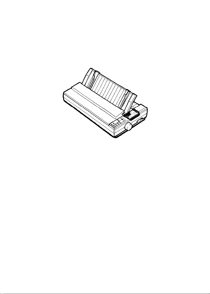
The Epson® LQ-1010 is an advanced 24-pin dot matrix printer
combining compact design and high performance with a wide range of
features.
Features
In addition to the high-quality printing and ease of operation you have
come to expect from Epson printers, the LQ-1010 offers the following
features:
Easy paper handling, featuring automatic single-sheet loading.
Compatibility with the Epson ESC/P® commands used by the
LQ-500, LQ-510, LQ-800, LQ-850, LQ-1000, LQ-1050, LQ-1500,
LQ-2500, and LQ-2550.
Fast draft mode printing of up to 180 characters per second at 12
cpi (characters per second).
An improved control panel design that allows direct selection of
character fonts, as well as a choice of normal or condensed
printing.
The SmartPark™ paper handling system that lets you use single
sheets of paper without removing the continuous paper, eliminates
paper waste with short tear-off, and allows easy and accurate paper
alignment.
Two built-in Letter Quality fonts (Roman and Sans Serif) for
producing high-quality documents.
A 360 x 360 dot per inch graphics mode.
A micro-adjustment feature that allows you to feed the paper
forward or backward to finely adjust the loading and short tear-off
positions.
Introduction 1
Page 10
Introduction
l
Fourteen international character sets, a legal symbol set, an italic
character table, and the Epson Extended Graphics character table.
l
The ability to handle a wide range of paper types, including
envelopes, labels, and wide carriage computer paper.
Options and Supplies
A variety of printer options is available for use with your LQ-1010
printer. For detailed information on installing and using these options,
see Chapter 5.
To locate or purchase accessories or supplies, contact your nearest
Epson dealer or call
l
Single-bin Cut Sheet Feeder
The cut sheet feeder makes it possible to handle single-sheet paper
easily and efficiently. Up to
be fed automatically into the printer without reloading.
1-800-873-7766.
(C806241)
150
sheets of standard bond paper can
Introduction
2
Page 11
Introduction
l
Pull Tractor Unit
This option improves the performance of continuous paper
handling. It is especially useful with continuous multi-part forms.
l
Multi-Font Module
The optional Multi-Font module adds to the number of fonts
available in the Letter Quality mode.
(C800141)
(#7407-A)
l
Film Ribbon Cartridge
(#7770)
The optional film ribbon cartridge provides you with even higher
quality printing than the standard fabric ribbon.
Introduction 3
Page 12
Introduction
l Interface Boards
Optional interface boards are available to supplement the printer’s
built-in parallel interface. Guidelines for choosing the right interface
and instructions on installing the boards are given in Chapter 5.
About This Manual
This user’s manual provides fully illustrated, step-by-step instructions
on setting up and operating your Epson LQ-1010 printer,
Finding your way around
• Chapter 1 contains information on unpacking, setting up, testing,
and connecting the printer. Be sure to read and follow these
instructions first. Inside the back flap of this manual are illustrations
of the printer in which all of the major parts are identified.
•
Chapters 2 and 3 cover paper handling and general printer
operation. This important information is necessary for the
day-to-day operation of your printer.
4 Introduction
Page 13

Introduction
l
Chapter 4 shows you how to get the most from your printer. It
includes advice on the use of software commands, graphics, and
creating your own user-defined characters. See Chapter 9 for a
useful summary of printer commands.
l
If the printer does not operate properly or the printed results are
not what you expect, see Chapter 7 for troubleshooting
instructions.
l
Other chapters and the appendix contain information on printer
options, general maintenance, and specifications. You will also find
a glossary of printer terms.
l
At the back of this manual is a handy Quick Reference card that
contains the information you are most likely to need.
Conventions used in this manual
WARNINGS
must be followed carefully to avoid damage to
your printer and computer.
CAUTIONS
should be followed carefully to ensure that your
printer operates correctly.
Notes contain important information and useful tips on the
operation of your printer.
Application Notes
Also included in the box with your printer is a booklet called
Application
Notes. It contains information on using specific software
applications with your printer. Be sure to look at the booklet after you
set up your printer.
Introduction 5
Page 14

Introduction
Where to Get Help
Customer support and service for Epson products are provided by a
network of authorized Epson dealers and Customer Care Centers
throughout the United States. Epson America provides product
information and support to its dealers and Customer Care Centers.
Therefore, we ask that you contact the business where you purchased
your Epson product to request assistance. If the people there do not
have the answer to your question, they can obtain it through our dealer
support program.
Epson is confident that this policy will provide you with the assistance
you need. Call the Epson Consumer Information Center at
1-800-922-8911
l
The location of the nearest Epson dealer
l
The location of the nearest Customer Care Center
l
Information on Epson User Groups.
for the following:
Introduction
6
Page 15

Chapter 1
Setting Up the Printer
Unpacking the Printer
Checking the Parts
Removing the Protective Materials
Choosing a Place for the Printer . . . . . . . . . . . . . . . . . . . . . . . . 1-5
Assembling the Printer
Installing the Platen Knob
Installing the Ribbon Cartridge
Attaching the Paper Guide
Testing the Printer
Plugging in the Printer
Running the Self Test
If the Self Test Does Not Work
Connecting the Printer to Your Computer
The Parallel Interface
Setting Up Your Application Software
Choosing From a Menu
................................
.................................
....................
.................................
...........................
.......................
...........................
....................................
..............................
...............................
.......................
................
...............................
...................
.............................
1-2
1-2
1-3
1-7
1-7
1-8
1-12
1-14
1-14
1-15
1-22
1-23
1-23
1-26
1-26
Setting Up the Printer
1-1
Page 16
Unpacking the Printer
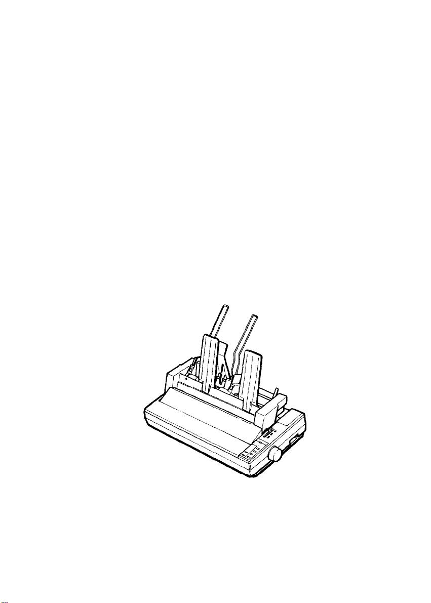
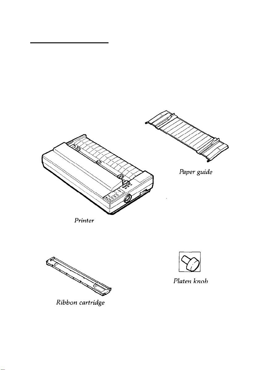
Checking the Parts
When you unpack the printer, make sure that you have all the parts
shown below and that none have been damaged.
1-2
Setting Up the Printer
Page 17
Unpacking the Printer
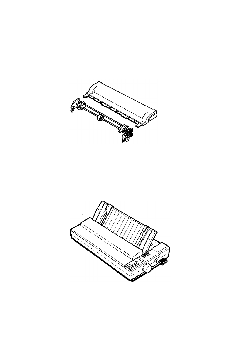
Removing the Protective Materials
The printer is protected during shipping by a locking clip. You must
remove this clip before turning on the printer.
WARNING:
tuning
is attached may seriously damage the mechanism.
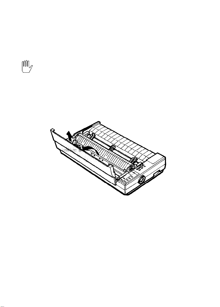
Follow these steps to remove the locking clip.
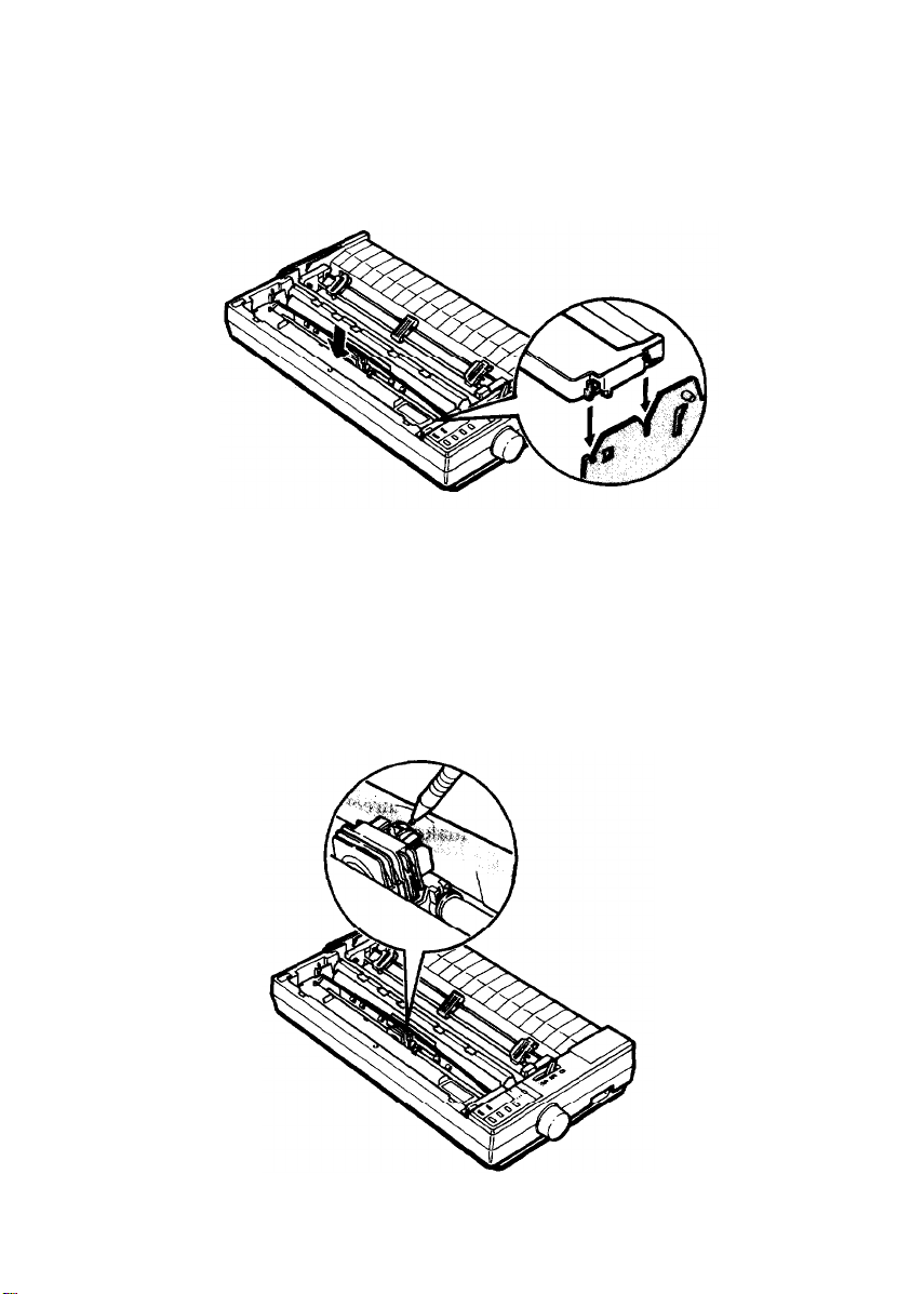
1.
Remove the printer cover.
Be sure you have removed the locking clip before
on
your printer. Turning on the printer while the clip
Setting Up the Printer
1-3
Page 18
Unpacking the Printer
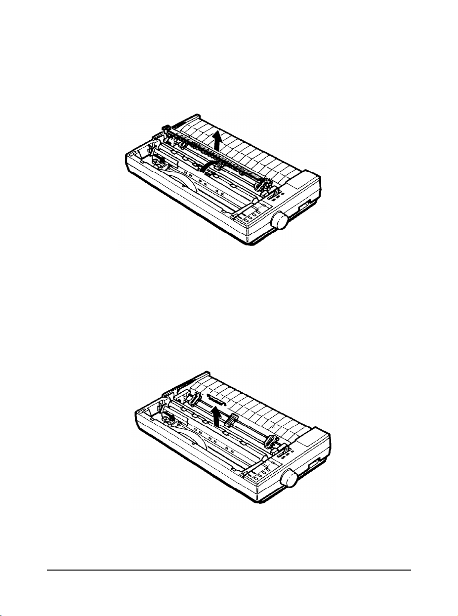
Remove the paper tension unit as shown below.
2.
3. Remove the locking clip.
Note: Store the clip with the other packing material in case you
ever need to transport your printer.
1-4 Setting up the Printer
Page 19

Choosing a Place for the Printer
There are several important things to consider when selecting a place to
set up your printer. Keep the following in mind:
Place the printer on a flat, hard, stable surface. A soft surface, such
as a padded counter or carpeted area, will block the ventilation
slots and may cause overheating.
Place the printer close enough to the computer for the printer cable
to reach.
Leave adequate room around the printer to allow for easy printer
operation and maintenance, and for unrestricted flow of air around
the printer.
Use a grounded outlet; do not use an adapter plug.
WARNING:
excessive heat, moisture, or dust.
Avoid electrical outlets controlled by wall switches or automatic
timers. Accidental interruption of power can wipe out information
in your computer’s memory and in your printer’s memory.
Avoid using outlets that share a circuit with large motors or
electrical appliances; this could cause fluctuations in line voltage.
Keep the entire computer system away from potential sources of
electromagnetic interference such as loudspeakers or the base units
of cordless telephones.
Avoid locations that are subject to direct sunlight,
Setting Up the Printer
1-5
Page 20
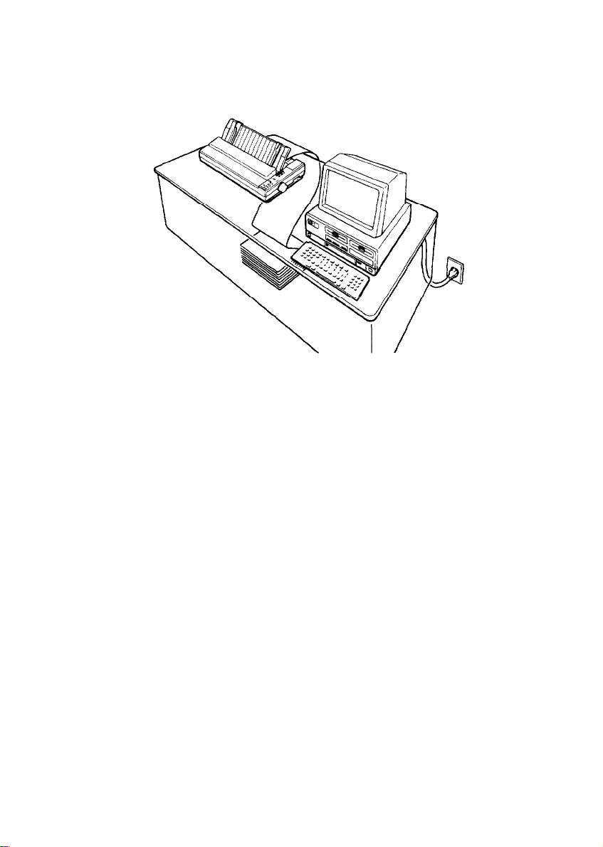
Choosing a Place for the Printer
The illustration below shows a good printer location.
Note: Before using a printer stand, read these requirements and
suggestions.
l
The stand should be able to support at least twice the weight of
the
LQ-1010
printer, or approximately 36 pounds
(16
kilograms).
l
Never use a stand that supports the printer at an angle of more
than 15 degrees from horizontal.
l
With a cut
l
If your paper supply is positioned below
sure there is enough
sheet
feeder, your printer must be kept level.
the
printer stand, make
clearance
to keep the paper from catching on
the underside of the stand. Also, make sure the distance between
the
stand supports is wide enough for the paper you are using.
l
Position your printer’s cables
so that
they do
not
interfere with
paper feeding. If possible, secure the cables to the printer stand.
1-6
Setting Up the Printer
Page 21
Assembling the Printer
After you’ve decided on the best place to set up your printer, the next
step is to install the platen knob.
WARNING: Be sure to remove the locking clip as described in
the Removing the Protective Materials section of this chapter
before proceeding.
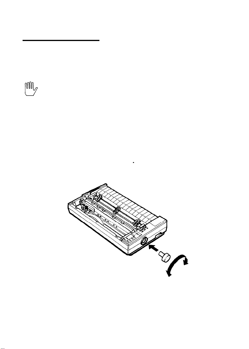
Installing the Platen Knob
The platen knob is used to feed the paper manually in the event of a
paper jam or other paper feeding problem. The platen knob is packed
in an indentation in the printer’s white foam packing material.
1. Insert the knob into the hole on the printer’s side and rotate it
slowly until it slips onto the shaft.
Setting Up the Printer
1-7
Page 22
Assembling the Printer
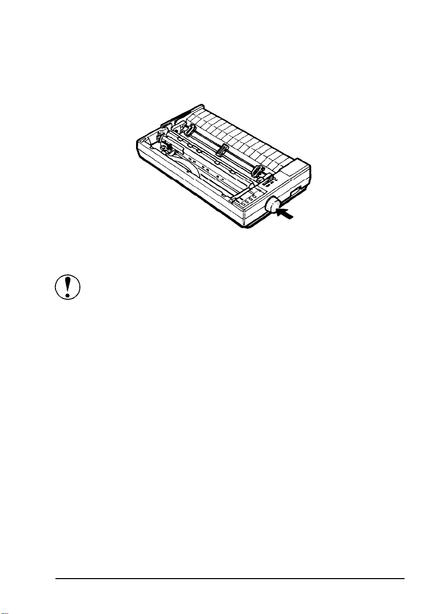
2. Push firmly on the platen knob until it fits against the printer case.
CAUTION: Do not use the platen knob to adjust the position
of the paper. This interferes with the automatic paper loading
system and may cause a paper jam.
Installing the Ribbon Cartridge
Your printer’s ribbon cartridge is designed for easy installation and
removal. Before installing the ribbon cartridge, make sure the printer is
turned off.
1-8 Setting Up the Printer
Page 23
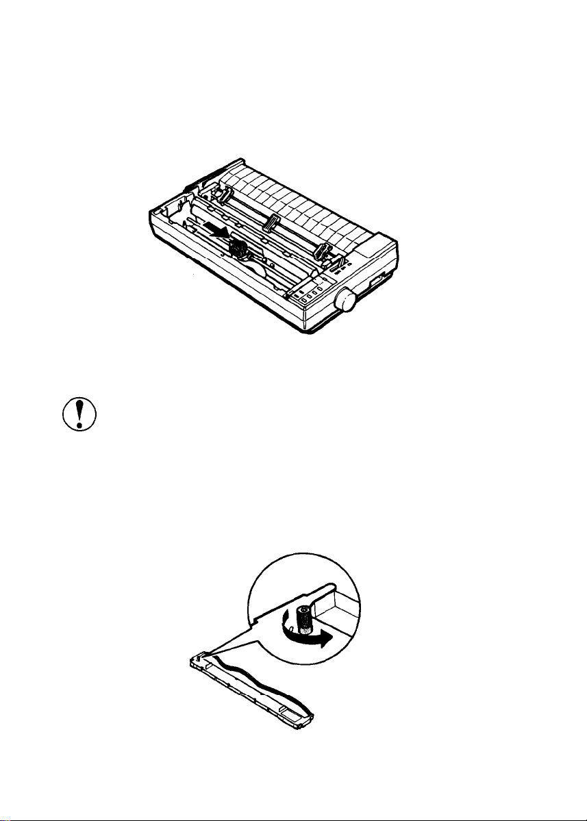
Install the ribbon cartridge as follows.
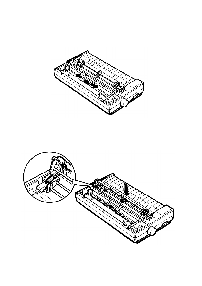
1.
Slide the print head to the middle of the printer.
Assembling the
Printer
CAUTION:
Never move the print head while the printer is
turned on because this can damage the printer. Also, if you
have been using the printer, the print head may be hot; let it
cool for a few minutes before touching it.
2.
Turn the ribbon-tightening knob in the direction of the arrow. This
removes slack in the ribbon and makes it easier to install.
Setting Up the Printer
1-9
Page 24
Assembling the Printer
Hold the ribbon cartridge by its handles and push it firmly down
3.
into position, making sure the plastic hooks fit into the slots.
Note: Press
plastic hooks are properly seated.
4.
Use a pointed object, such as a ball point pen, to guide the ribbon
between the print head and ribbon guide while you turn the
ribbon-tightening knob to help feed the ribbon into place.
lightly on both ends of the cartridge to make sure the
1-10
Setting Up the Printer
Page 25
Assembling the Printer
5. Slide the print head from side to side to make sure it moves
smoothly. Also check that the ribbon is not twisted or creased.
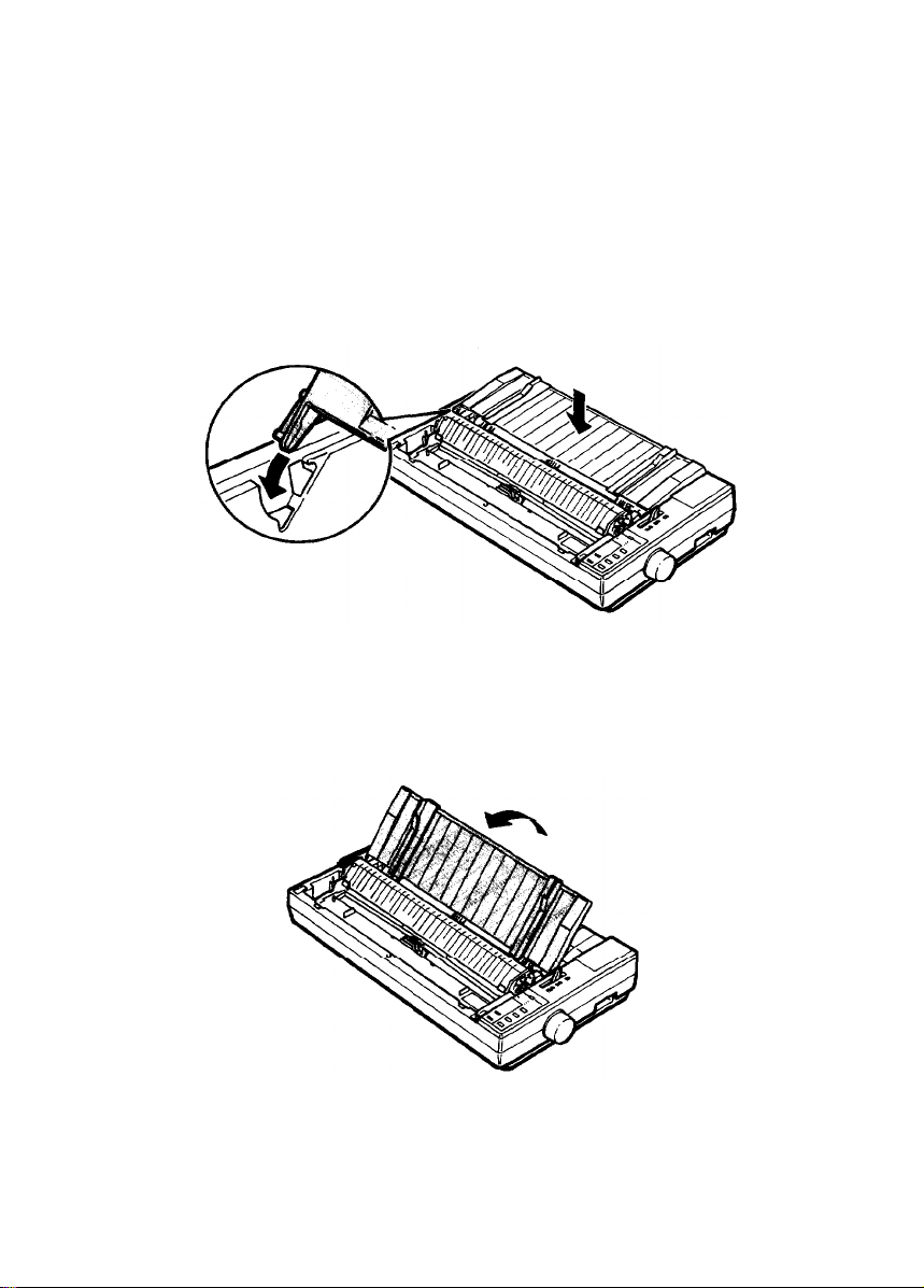
6. Fit the rear notches of the paper tension unit over the pins of the
printer. Lower the unit, pressing on both sides to lock it in place.
Setting Up the Printer
1-11
Page 26
Assembling the Printer
Attaching the Paper Guide
When you use single sheets, the paper guide helps to feed the paper
smoothly and efficiently into the printer. Attach the paper guide using
the following procedure.
Place the paper guide on the printer as shown below.
1.
2.
Raise the paper guide until it locks into place.
1-12
Setting Up the Printer
Page 27
Assembling the Printer
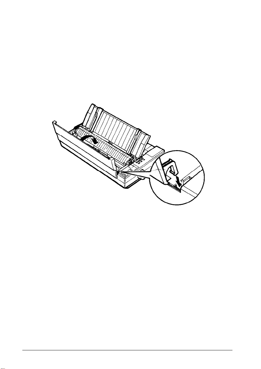
Note:
its locked position; then gently lower it down onto the printer.
3. Attach the printer cover by fitting the hooks on the cover into
notches at the front of the printer and tilting the cover back into
place.
To lower the paper guide, lift up slightly to release it from
the
Setting Up the Printer
1-13
Page 28
Testing the Printer
Now that your printer is fully assembled, you can use its built-in self
test function to see that the printer is working correctly before you
connect it to a computer. You should perform this test to make sure that
your printer was not damaged during shipping and that the ribbon is
correctly installed.
Before running the self test, you need to connect the printer to an
electrical outlet and load a sheet of paper.
Plugging in the Printer
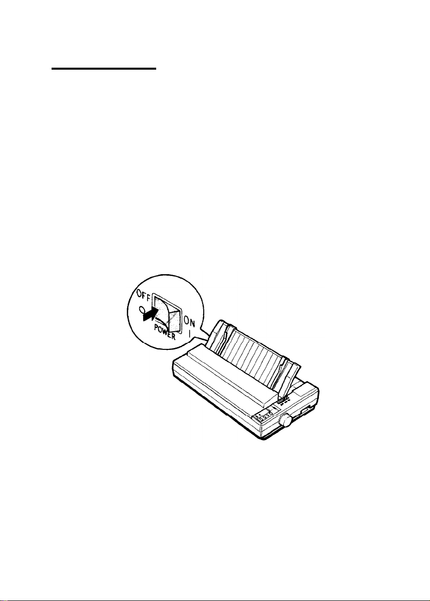
1.
Make sure that the printer is turned off.
1-14
Setting Up the Printer
Page 29
Testing the Printer
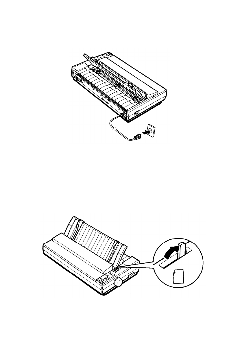
2.
Plug the power cable into a properly grounded electrical outlet.
Running the Self Test
The self test can be run in the draft or Letter Quality mode, depending
on which button you hold down as you turn on the printer. Although
the self test can be run with continuous paper, use single-sheet paper
now because single-sheet loading is easier.
1.
Make sure the printer is turned off.
2. Push the paper release lever back to the single-sheet position.
Setting Up the Printer
1-15
Page 30
Testing the Printer
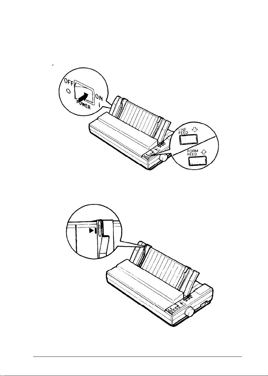
While holding down the
3.
FEED
button (Letter Quality mode), turn on the printer. The printer
beeps several times and
Move the left edge guide
4.
mark.
LINE FEED
POWER
and
so that
button (draft mode) or
PAPER OUT
it locks in place
lights come on.
next to the
FORM
guide
1-16
Setting Up the Printer
Page 31

Testing the Printer
5.
Adjust
the
right edge guide to match
the
width of your paper. Next,
slide a sheet of paper down between the edge guides until it meets
resistance.
WARNING: Never run the self test using paper that is
narrower than 14 inches (legal paper turned sideways) to
prevent
the
print head from printing directly onto
the
platen.
6.
Press the LOAD/EJECT
button to load the paper.
Setting Up the Printer
1-17
Page 32

Testing the Printer
7.
Press the
settings is printed first, followed by a series of characters. The self
test continues until the paper runs out or until you press
LINE
8.
If the test results are satisfactory and you wish to stop the test,
press the
Checking the Operation later in this chapter for possible causes and
solutions.
ON LINE
button.
ON LINE
button to start
button. If the test results are not satisfactory, see
the
self test. A list of DIP switch
the ON
1-18
Note:
To resume the test, press the
Setting Up the Printer
ON LINE
button once more.
Page 33

9.
If the paper is still loaded, press the
FEED
button to eject it. Then turn off the printer.
LOAD/EJECT
Testing the Printer
button or
LINE
WARNING:
five seconds before turning it back on. Turning the power on
and
off rapidly can damage the printer.
After turning the power off, always wait at least
Setting Up the Printer 1-19
Page 34

Testing the Printer
Here is part of a typical self test printed in draft mode.
Draft mode
Country SW1-1 1-2 1-3
USA
France
Germany
U.K.
Denmark
Sweden
Italy
Spain
Font
Roman
Sans serif
Slot,
Draft
Condensed
Invalid
on on on
on on off
on
off on Tear off mod
on
off off Invalid
off on on
off on off
off off on Invalid
off off off
SW1-4 1-5
off off Invalid
on
off
off on Receive buff
on on
SW1-6
off Graphics pri
Page length
11”
12”
Valid
1” Skip
Valid
Auto LF
Valid
1kbytes
8kbytes
Note: When using the optional cut
sheet
feeder, the first page of
self test printout is slightly different. For details, see the Cut Sheet
Feeder section in Chapter 5.
1-20
Setting Up the Printer
the
Page 35

Testing the Printer
Here is part of a typical self test printed in Letter Quality mode.
Letter Quality mode
Country
USA
France
Germany
U.K.
Denmark
Sweden
Italy
Spain
Font
Roman
Sans serif
Slot
Draft
SW1-1 1-2 1-3
on on on
on on off
off on
on
on off off
off on on
off on off
off off on
off off off
SW1-4 1-5
off off
off
on
off on
on on
Page length
11”
12”
Tear off moc
Invalid
Valid
1"Skip
Invalid
Valid
Auto LF
Invalid
Valid
Receive buff
1kbytes
Setting Up the Printer
1-21
Page 36

Testing the Printer
If the Self Test Does Not Work
If the self test does not print properly, check the control panel and the
print head area. If paper is jammed, turn off the printer. Then remove
the paper using the platen knob and load a new sheet. Make sure that
all packing material and shipping restraints have been removed from
inside the printer. See the Removing the Protective Materials section in
this chapter for information on removing the locking clip. You can also
see Chapter 7 for further information.
Problem Solution
The printer sounds like
it is printing, but
nothing is printed.
The test did not print
when you pressed the
ON LINE
button.
The ribbon may not be installed properly.
Turn off the printer, reinstall the ribbon
cartridge, and then tighten the ribbon by
turning the ribbon-tightening knob. Make
sure the ribbon passes between the print head
and ribbon guide. See page 1-10.
The ribbon may be worn. Replace the ribbon
cartridge. See page 6-5.
Turn off the printer and repeat the self test.
Make sure you hold down the
LINE FEED
turning on the printer.
Turn off the printer and disconnect the cable
from the host computer. Try the self test
again.
If the printer still does not print the self test
correctly, contact your Epson dealer.
button the entire time you are
FORM FEED
or
1-22
Setting Up the Printer
Page 37

Connecting the Printer to Your Computer
If the self test printed correctly, you are now ready to connect the
printer to your computer.
If your computer has a parallel interface and you have a suitable
shielded cable, you should be able to connect your printer immediately.
The steps below describe how to connect the parallel interface cable.
If your computer requires another type of interface, you need to install
an optional interface board. See the Interface Boards section in
Chapter 5.
If you are not sure which type of interface cable is required, see your
computer manual.
The Parallel Interface
Connect the parallel interface cable as described below:
1.
Make sure that both your printer and computer are turned off.
Setting Up the Printer
1-23
Page 38

Connecting the Printer to Your Computer
2.
Plug the cable connector securely into the printer.
3.
Squeeze the wire clips together until they lock in place on either
side of the connector.
1-24
Setting Up the Printer
Page 39

Connecting the Printer to Your Computer
4.
If your cable has a ground wire, connect it to the ground screw
beneath the interface connector.
Plug the other end of the cable into the computer. If there is a
5.
ground wire at the computer end of the cable, attach it to the
ground connector at the back of the computer.
Setting Up the Printer
1-25
Page 40

Setting Up Your Application Software
Now that you
sure that it works with your application programs.
Most application programs let you specify the type of printer you are
using so that
features. Many of these programs provide an installation or setup menu
that presents a list of printers to
If your application program has a printer selection menu, use
instructions below.
have
set up and tested the
the
program can take full advantage of the printer’s
choose
LQ-1010,
from.
you should make
the
Choosing From a Menu
Because the family of Epson printers shares a great many commands,
you can use
on its printer selection menu. If the
the following printers. They are listed in order of preference.
an
application program even if it does not list
LQ-1010
is not listed, choose one of
the
LQ-1010
LQ-1050
LQ-2550
LQ-2500
LQ-1000
LQ-1500
If none of these printers is listed, select the first one available on the
following list:
LQ
EX
FX
To use all of
program with the
the
LQ-1010,
available that supports the
1-26
Setting Up the Printer
LX Epson printer
Rx
MX Draft printer
the
features of the
LQ-1010
contact
the
LQ-1010
Standard printer
LQ-1010,
on its menu. If your program does not list
software manufacturer to see if an update is
however, it is best to use a
model.
Page 41

Chapter 2
Paper Handling
Selecting a Paper Feeding Method
Using Single Sheets
Loading Paper
Reloading During Printing
Using Continuous Paper
Positioning Your Continuous Paper Supply
Loading Continuous Paper
Switching Between Continuous and Single Sheets
Switching to Single Sheets
Switching Back to Continuous Paper
Printing on Special Paper
The Paper Thickness Lever
Multi-part Forms
Labels
Envelopes
............................................
.........................................
...................................
.....................................
.............................. 2-7
..............................
...................................
.......................
..........................
.............
.........................
...........................
..................
..........................
.........
2-2
2-3
2-3
2-6
2-7
2-8
2-16
2-16
2-21
2-24
2-24
2-27
2-28
2-30
Paper Handling 2-1
Page 42

Selecting a Paper Feeding Method
The paper release lever on the LQ-1010 has three positions for use with
the
various methods of paper feeding. Make sure
is set to
The lever positions are marked by three icons, as described below.
match
the desired paper feeding method.
Single-sheet mode: When you load single sheets from either the
paper guide or from the optional cut sheet feeder, the lever
should be set all the way back to the single-sheet position.
the
paper release lever
2-2
Push tractor mode: When you load continuous paper with the
built-in push tractor, the lever should be set in the middle,
which is the push tractor position.
Pull tractor mode: When you load continuous paper with the
optional pull tractor, the lever should be set all the way forward
to the pull tractor position. Even when you use the built-in push
tractor with the pull tractor, you must set the lever to this
position. Select this position only if you are using the optional
pull tractor.
Paper Handling
Page 43

Using Single Sheets
Your printer can accommodate single sheets with a width of 7.2 inches
or 182 mm to 14.3 inches or 364 mm.
If you do most of your printing on single sheets, you may find it more
convenient to install the optional cut sheet feeder. This option
automatically inserts a new sheet and can hold up to 150 pages. For
more details, see Chapter 5.
Loading Paper
1.
Push the paper release lever back to the single-sheet position.
Paper Handling 2-3
Page 44

Using Single Sheets
2.
Turn on
the
printer. (The green
POWER
light should come
on.)
Note: Do
not
insert paper in
the
printer before turning on the
printer.
3.
Move the left edge guide so that it locks in place next to the guide
mark. (You
the margin settings of your application program.)
may
want to change this position later, depending on
2-4
Paper Handling
Page 45

Using Single Sheets
4.
Adjust the right edge guide to match the width of your paper. Then
slide
the
paper down between the edge guides until it meets
resistance.
5. Press the
CAUTION: Never advance
while the printer is turned
loading
firmly. Then press the
LOAD/EJECT
the
paper, remove the paper and reinsert it more
button once to load the paper automatically.
the
paper using
on.
If the platen turns without
LOAD/EJECT
button again.
the
platen knob
Paper Handling 2-5
Page 46

Using Single
6.
Press the
LINE
You are now ready to begin printing.
Sheets
ON LINE
light is lit, the printer can accept data from your computer.
button to set the printer on line. When the
ON
Reloading During Printing
When you print a document of more than one page using single-sheet
paper, the printer stops printing when it reaches the bottom of the page.
When this happens, the
remains on, depending on your application program software. If the
LINE
light remains on, the first thing you should do is press the
button to take the printer off line.
ON LINE
light either goes off automatically or
ON
ON LINE
Once the
printed (if necessary, press the
load a new sheet. Press the
page and follow any additional prompts from your software. Be sure
that
number of lines that can be printed on your paper.
2-6
ON LINE
the page length or form
light is off, remove the sheet that has just been
ON LINE
Paper Handling
LOAD/EJECT
button to start printing the next
length
setup in your software matches the
button to eject the page) and
Page 47

Using Continuous Paper
The push tractor built into your
load and operate. Its low-profile design takes up little space and can
handle paper up to
16
inches or 406 mm wide.
LQ-1010
printer is remarkably easy to
Positioning Your Continuous Paper Supply
An important consideration for achieving smooth and trouble-free
paper feeding is the position of your paper supply.
Three ways of positioning your printer and continuous paper supply
are shown below.
Paper Handling 2-7
Page 48

Using Continuous Paper
Be sure to align the paper supply with the paper loaded in the tractor so
that the paper feeds smoothly into the printer.
Loading Continuous Paper
Be sure that the printer
1.
is
turned off, then remove the paper guide.
2-8 Paper Handling
Page 49

Using Continuous Paper
2.
Set the paper release lever to the push tractor paper position, which
is the middle setting. This position is marked by the icon shown in
the illustration below.
3.
Release the sprocket units by pulling the sprocket lock levers
forward as shown below.
Paper Handling 2-9
Page 50

Using Continuous Paper.
4.
Slide the left sprocket unit until it is about 1 inch (25 mm) from the
farthest left position and press the lever back to lock it in place.
5.
Slide the right sprocket unit so that it roughly matches the width of
your paper, but do not lock it.
2-10
Paper Handling
Page 51

Using Continuous Paper
6.
Move the paper support midway between the two sprocket units.
7. Open both sprocket covers.
Paper Handling 2-11
Page 52

Using Continuous Paper
8. Fit the first
9. Close the sprocket covers.
three holes in the paper over the pins of both
CAUTION: Make sure that your paper has a clean, straight
edge before inserting it into the printer.
sprockets.
2-12
Paper Handling
Page 53

Using Continuous Paper
10.
Slide the right sprocket unit to a position where the paper is straight
and has no wrinkles. Then lock it in place.
11. Reattach the paper guide as shown below. Then slide the edge
guides apart to the sides of the paper guide as shown.
Paper Handling 2-13
Page 54

Using Continuous Paper
12.
Turn on the printer. It will beep because there is no paper in
printer. Then press
loading position.
the LOAD/EJECT
button to feed paper to the
the
13. Press the
accept data.
2-14
Paper Handling
ON LINE
button to set the printer on line so that it
can
Page 55

Using Continuous Paper
The printer remembers the loading position and advances each page to
the same position. If you need to adjust the loading position, use the
micro-adjustment feature. See the section on setting the loading
position in Chapter 3.
CAUTION: Never adjust the loading position using the
platen knob and never turn the platen knob while the printer
is turned on.
Before you begin printing, be sure to check the page length and skip
over perforation settings, and readjust these settings if necessary. See
the sections on page length and skip over perforation in Chapter 3.
Paper Handling
2-15
Page 56

Switching Between Continuous and Single Sheets
Even with continuous paper loaded in the printer, the SmartPark
feature allows you to easily switch to single-sheet printing without
removing the continuous paper from the tractor.
Switching to Single Sheets
To switch from continuous paper to single sheets, follow the steps
below.
1.
If the printer is on line, press the
off line.
ON LINE
button to set the printer
2-16
Paper Handling
Page 57

Switching Between Continuous and Single Sheets
2. Tear off any outgoing sheets. If your printed document has not
advanced past the print head, you need to press
button to advance your document to a point where it can be easily
removed.
CAUTION: Make sure you tear off your printed document
before pressing the
LOAD/EJECT
button. Reverse-feeding
several pages at a time may result in a paper jam. This is
especially true for narrow paper (less
152.4
mm wide).
the FORM FEED
than
6 inches or
Paper Handling
2-17
Page 58

Switching Between Continuous and Single Sheets
3.
Press the
backward out of the printer and into the standby position. The
paper is still attached to the tractor but is no longer in the paper
path.
LOAD/EJECT
button to feed the continuous paper
2-18
CAUTION: Pressing the
feed the paper far back enough to reach the standby position.
If the
PAPER OUT
the
LOAD/EJECT
paper, you
times. If, however, you are using narrow paper (between 4
and 6 inches or 101.6 and 152.4 mm) you should only press
the LOAD/EJECT button once. Also, do not use this button to
eject labels.
WARNING: Never feed labels backward through the printer.
Labels can easily come off the backing sheet and jam the
printer.
light does not come on, you need to press
button again. With normal-width continuous
can
press
LOAD/EJECT
the LOAD/EJECT
button once may not
button up to three
Paper Handling
Page 59

Switching Between Continuous and Single Sheets
4.
Push the paper release lever back to the single-sheet position. This
position is marked by the icon shown in the illustration below.
5.
Stand the paper guide upright and adjust the edge guides to roughly
match the width of your paper.
Paper Handling
2-19
Page 60

Switching Between Continuous and Single Sheets
6.
Insert a sheet of paper between
meets resistance. Slide
the
the
edge guides until
edge guides to exactly match
your paper.
7.
Press the
paper to the loading position. Then, press the
the
LOAD/EJECT
printer on line.
button to automatically feed the single-sheet
ON LINE
the
bottom
the
width of
button to set
2-20
Paper Handling
Page 61

Switching Between Continuous and Single Sheets
Switching Back to Continuous Paper
It is also easy to switch back to printing with continuous paper. Before
switching to continuous paper, make sure that the single sheet is ejected
and the printer is off line.
1.
Slide the edge guides apart so they do not interfere with continuous
paper feeding.
2. Lower the paper guide onto the printer.
Paper Handling
2-21
Page 62

Switching Between Continuous and Single Sheets
3. Pull the paper release lever forward to the middle (push tractor)
position for continuous paper feeding.
4.
Press
the LOAD/EJECT
loading position.
button to feed the continuous paper to the
2-22
Paper Handling
Page 63

5.
Press the
accept data.
ON LINE
Switching Between Continuous and Single Sheets
button to set the printer on line
so that
it can
Paper Handling
2-23
Page 64

Printing on Special Paper
In addition to printing on single sheets and continuous paper, your
printer can also print on a wide variety of paper types, including
multi-part forms, labels, and envelopes.
Before printing on special types of paper, you need to change the paper
thickness setting.
WARNING: When printing on multi-part forms, labels, or
envelopes, make sure that your application program settings
keep the printing entirely within the printable area.
For multi-part forms and labels you should not print any
closer than one-half inch from either side of the paper.
For information on the printable area for envelopes, see page
2-31.
The Paper Thickness Lever
To accommodate various thicknesses of paper, the LQ-1010 is equipped
with a paper thickness lever that can be set to eight positions. These
positions are identified by a scale on the printer next to the lever. (See
the chart on page 2-26.)
2-24
Paper Handling
Page 65

Printing on Special Paper
To change the paper thickness setting, follow these steps.
1.
Make sure that the printer is turned off. Then remove the printer
cover.
WARNING: If the printer has just been in use, the print head
may be hot. Allow it to cool before touching it.
2. Select the paper thickness you want according to the table on the
following page. For normal use, the lever should always be set to
position 2 on the scale.
To help you check the position of the paper thickness lever, the
orange
MULTI-PART
light on the control panel comes on if the lever
is set to position 4 or higher.
Paper Handling
2-25
Page 66

Printing on Special Paper
Paper Type
Paper (single sheets or continuous)
Thin paper
24 lb paper
Lever Position
2
2
3
Multi-part forms
2-sheet
3-sheet
Labels
3
4
4
Envelopes
Air mail
Plain
Bond (20 lb)
Bond (24 lb)
Note: Lever position 1 is used only when the printed characters
are too light. Setting the lever to position 1 when you are using
thin paper may damage the print head. Also, if the lever is set to
position 4 or higher, the printing speed may be reduced slightly.
4 or 5
6
6
7
2-26
Paper Handling
Page 67

3.
Reattach the printer cover as shown below.
Printing on Special Paper
WARNING:
go back to printing on ordinary paper. Continuous printing
with the lever set at a position higher than 2 can shorten the
life of the print head. Also note that printing past the edge of
envelopes, multi-part forms, labels, or thicker-than-normal
paper can damage the print head.
Always return the lever to position 2 when you
Multi-part Forms
With the built-in tractor unit, your printer can print on continuous
multi-part forms. You can use multi-part forms that have up to three
parts including the original. Make sure you set the paper thickness lever
to the proper position; see the table on page 2-26.
Paper Handling
2-27
Page 68

Printing on Special Paper
Except for the paper thickness lever setting, you load multi-part paper
the same way as continuous paper. For details, see the section on
loading continuous paper in this chapter. Also see the sections on
setting the loading position and page length in Chapter 3.
CAUTION:
single-sheet feeding system or the optional cut sheet feeder.
Multi-part forms should not be used with the
Labels
If you need to print labels, always use labels mounted on a continuous
backing sheet with sprocket holes for use with a tractor. Do not try to
print labels as single sheets because labels on a shiny backing sheet
almost always slip a little.
2-28
Paper Handling
Page 69

Printing on Special Paper
You load labels the same way that you load continuous paper except
that the paper thickness lever must be adjusted for printing labels. See
the section on loading continuous paper earlier in this chapter. For the
correct paper thickness setting, see the table on page 2-26.
WARNING:
Labels can easily peel off the backing and
Therefore, never use the LOAD/EJECT button to eject labels.
Also,
never
sure to set DIP switch
stuck in the printer, contact your Epson dealer.
Since labels are especially sensitive to temperature and
humidity, always use them under normal operating
conditions. Don’t leave labels loaded in the printer between
jobs;
they
resume printing.
Never feed labels backward through the printer.
jam the
use the short tear-off function with labels.
2-2
to off.) If a label does become
curl around the platen and may jam when you
printer.
(Be
Paper Handling
2-29
Page 70

Printing on Special Paper
Envelopes
You can feed envelopes individually using the single-sheet loading
feature. Before loading envelopes, adjust
thickness lever according to the table on page
handling, see Using Single
When manually feeding an envelope, you may have to push it down
slightly while pressing the
Sheets
on page
LOAD/EJECT
the
position of the paper
2-26.
For details on paper
2-3.
button to get it to feed properly.
2-30
CAUTION:
The printable area for envelopes is shown on the
next page. The print head must not go past the left or right
edge of the envelope or other thick paper. Make sure that
your application program page setup keeps the printing
entirely within this printable area.
Paper Handling
Page 71

Printing on Special Paper
CAUTION:
temperature (41°F to 95°F or 5°C to 35°C).
To make sure that the printing fits within the printable area, always
print a test sample using a normal sheet of paper before printing on
envelopes.
Envelope printing is only available at normal
Paper Handling
2-31
Page 72

Chapter 3
Using the Printer
Operating the Control Panel . . . . . . . . . . . . . . . . . . . . . . . . . . . 3-2
Setting the DIP Switches
Changing a DIP Switch Setting
The DIP Switch Tables
The DIP Switch Functions
Page Length . . . . . . . . . . . . . . . . . . . . . . . . . . . . . . . . . . . . . . 3-10
Skip Over Perforation . . . . . . . . . . . . . . . . . . . . . . . . . . . . . . . . 3-11
Adjusting the Loading Position
The Loading Position
Using Micro-adjustment
Using Short Tear-off
Adjusting the Tear-off Position
Selecting Typestyles
Character Fonts
Condensed Mode
Selecting an International Character Set
....................................
..............................
.......................
.............................
...........................
.........................
...............................
.............................
................................. .3-15
.......................
..................................
..................................
. . . . . . . . . . . . . . . . . 3-22
3-6
3-6
3-7
3-9
3-12
3-12
3-13
3-16
3-19
3-20
3-21
Choosing a Character Table . . . . . . . . . . . . . . . . . . . . . . . . . . . 3-24
Using the Data Dump Mode . . . . . . . . . . . . . . . . . . . . . . . . . . . 3-26
Using the Printer 3-1
Page 73

Operating the Control Panel
The indicator lights give you the current status of the printer. The
buttons and paper handling functions let you control many of the
printer settings.
Lights
MULTI-PART (orange)
On when the paper thickness
lever is set to position 4 or
higher. When this light is
blinking, the micro-adjustment
function can be used.
POWER
On when the POWER switch is on
and power is supplied.
READY
On when the printer is ready to
accept input data. Flickers during
printing.
(green)
(green)
PAPER OUT (red)
On when the printer is out of
paper or when continuous paper
is in the standby position.
ON LINE (green)
On when the printer is on line
and ready to accept data.
3-2
Using the Printer
Page 74

Buttons
Operating the Control Panel
ON LINE
This button controls the printer’s
on line and off line status. Press
this button to put the printer on
line or to take it off line. When
the printer is on line, the
light is on and the printer can
receive and print data from the
computer.
FORM FEED
When the printer is off line, press
this button to eject a single sheet
of paper or to advance
continuous paper to the top of
the next page.
LINE FEED
When the printer is off line, press
this button to advance the paper
one line, or hold it down to
advance the paper continuously.
ON LINE
LOAD/EJECT
This button is used to feed paper
to the loading position or to eject
paper that is already loaded.
Paper is ejected forward if the
paper release lever is set to the
single-sheet position and
backward (out of the paper path)
if the release lever is set to the
continuous paper position.
Using the Printer 3-3
Page 75

Operating the Control Panel
SelecType
FONT
This button is used to select LQ
ROMAN, LQ SANS SERIF, DRAFT
mode, or a cartridge font (if
installed). The two orange
indicator lights
font. See Selecting Typestyles
later in this chapter.
CONDENSED
This button is used to turn
condensed mode on and off. The
orange indicator light is on when
the printer is in the condensed
mode. In the condensed mode,
all characters are printed at
approximately 60 percent of their
normal width.
show
the selected
the
3-4
Using the Printer
Page 76

Operating the Control Panel
Other control panel features
The control panel of your printer also gives you access to several
special functions.
Self test:
Micro-adjustment:
Data dump:
Both a draft and Letter Quality self test function
are built into the printer. The self test printout lets
you check the current DIP switch settings and
operating status of the printer. You can start the
printer’s self test by holding down
button or the
the printer. See
Chapter 1 for more information.
By pressing the
after loading paper or when using short tear-off,
you can make fine adjustments to the loading and
short tear-off positions. These positions can be
adjusted only while the
blinking. See
position and using
in this chapter.
By holding down both the
FEED
buttons while you switch on the printer, you
turn on the data dump mode. This feature allows
advanced users to locate the source of
communications problems between the computer
and printer. See the section on using the data dump
mode on page
FORM FEED
the
FORM FEED
the
sections on adjusting the loading
3-26
button while turning on
section on the self test in
button immediately
MULTI-PART
the
short tear-off function later
LINE FEED
for more information.
the LINE FEED
light is
and
FORM
Using the Printer 3-5
Page 77

Setting the DIP Switches
The LQ-1010 has two sets of DIP (Dual Inline Package) switches located
under a small cover above the control panel. By changing the settings
of these switches, you can control various printer features, such as the
character set and page length. The new settings become effective when
the printer is turned on, reset, or initialized.
DIP switch settings are shown in the DIP switch tables starting on page
3-7. Descriptions of all the DIP switch functions begin on page 3-9.
Changing a DIP Switch Setting
To change a DIP switch setting, first turn off the printer. Then open the
DIP switch cover and use a pointed object, such as a pen, to change the
DIP switch settings. A DIP switch is on when it is up, and off when it is
down.
The new DIP switch settings take effect when the printer is turned on.
3-6
Using the Printer
Page 78

Using the Printer
The DIP Switch Tables
The tables below show the settings for each DIP switch. The shaded
areas show the default or factory settings.
DIP switch 1
DIP switch 2
* Required for use of user-defined (download) characters.
** When on and ESC U0 is input, multi-pass characters are printed bi-directionally.
Using the Printer
3-7
Page 79

Setting the DIP Switches
Table 1
International character sets
Table 2 Font selection
Font
Roman
Sans Serif
Slot
Draft
Table 3
Character spacing
SW1-4
OFF
ON
OFF
ON ON
SW1-5
OFF
OFF
ON
Spacing
10 cpi
12 cpi
15 cpi
Proportional
cpi: characters per inch.
3-8
Using the Printer
SW2-7
OFF
ON
OFF ON
ON ON
SW2-8
OFF
OFF
Page 80

The DIP Switch Functions
Auto line feed
When auto line feed is on (DIP switch
code (CR) is automatically followed by a line feed code (LF).
2-4
on),
each
carriage return
Input buffer capacity
The input buffer stores data from your computer. If you
your computer for other tasks while the printer prints, change the
setting of switch
however, be sure to set the input buffer to 1 KB (off).
2-5
to 8 KB (on). Before using user-defined characters,
want
to free
Tear-off mode
When DIP switch
automatically advances continuous paper to the tear-off position, and
then
reverse-feeds the paper to the loading position. See the section on
using short tear-off later in this chapter.
2-2
is on,
the
short tear-off mode is
on.
This feature
CAUTION:
Do not use the short tear-off mode with labels.
Print direction of multi-pass characters
Multi-pass characters are normally printed unidirectionally. If DIP
switch
bi-directionally.
2-6
is on and ESC
U0
is input, multi-pass characters are printed
Using the Printer
3-9
Page 81

Page Length
When the setting of DIP switch 2-1 is off, the page length is set to 11
inches, or 279.4 mm. When it is on, the page length is 12 inches, or
304.8 mm. Be sure to set the page length to match the paper you are
using.
Other page lengths can be set using the commands ESC C and ESC C 0.
See the Command Summary in Chapter 9 for details.
If you are using the built-in push tractor, you can also select 8.5 inches
as the page length by using the control panel. When the printer is on
line, press the
length. The printer beeps four times to signal that the 8.5-inch length
has been selected. If you press the
beeps three times and returns to the page length selected by DIP switch
2-1.
3-10
LOAD/EJECT
button once to select the 8.5-inch page
Using the Printer
LOAD/EJECT
button again, the printer
Page 82

Skip Over Perforation
By changing the setting of DIP switch 2-3, you can set skip over
perforation to on or off. If this feature is on when using continuous
paper, a one-inch margin is provided between the last printable line on
one page and the first printable line on the next page. This feature is
very convenient if your application program does not provide for top
and bottom margins.
If you adjust your loading position correctly, you can get half of the
-
margin at the bottom of one page and half at the top of the next page,
as shown in the following illustration.
DIP switch 2-3 ON (Skip over perforation ON)
-
-
-
-
Note:
margins. Use skip over perforation only if your program does not
provide these margins.
The skip over perforation setting can be set to values other than one
inch by using
Chapter 9 for details.,
Most application programs take care of top and bottom
the
ESC N command. See the Command Summary in
Using the Printer
3-11
Page 83

Adjusting the Loading Position
The Loading Position
The loading position is the position of the paper when it has been
loaded automatically by the printer.
This position is important because it determines where the printing
begins on the page. If the printing is too high or too low on the page,
change the loading position using the micro-adjustment feature
described in the next section.
CAUTION:
case of a paper jam or other paper feeding problem. (If you
need to use the platen knob, make sure the power is off .) If
you need to adjust the loading position, always use the
micro-adjustment feature.
Until the loading position is reset, the printer remembers this position
even if it is turned off, and uses it as a reference point for feeding paper.
The micro-adjustment feature moves the paper in 1/180-inch
increments to make fine adjustments to the loading position. Once you
have used micro-adjustment to change the loading position of
continuous paper, the printer remembers that position even after it is
turned off.
When you use micro-adjustment to change the loading position of
single-sheet paper, however, the printer does not remember this position
after the power is turned off. When the power is turned back on, the
loading position returns to its factory setting.
Never use the platen knob to feed paper except in
3-12
Using the Printer
Page 84

Adjusting the Load Position
Using Micro-adjustment
1.
Make sure that the printer is turned on and that either a single sheet
or continuous paper is ready to be loaded.
2.
Press the LOAD/EJECT
Then press the
blink.
button to feed paper to the loading position.
ON LINE
button;
the MULTI-PART
light begins to
MULTI PART
Note:
micro-adjustment only while the
You
can
use the FORM FEED
and
LINE FEED
MULTI-PART
light is blinking.
Using the Printer
buttons for
3-13
Page 85

Adjusting the Loading Position
3. Press the FORM FEED button to feed the paper forward or the LINE
FEED
button to feed the paper backward.
Note: When the Paper
the printer beeps and micro-adjustment feeding pauses for a
moment before continuing. You can use this factory setting as a
reference point when adjusting the printer’s loading position.
When the paper reaches either the minimum or maximum top
reaches the factory-set loading position,
margin, the printer beeps and the paper stops moving.
3-14
Using the Printer
Page 86

Using Short Tear-Off
When you are finished printing, the short tear-off feature automatically
feeds the perforation of the continuous paper to the tear-off edge of the
printer cover so that you can tear off the last sheet. When you resume
printing, the paper feeds backward to the loading position. This feature
lets you save the paper normally lost between documents.
To use this feature, set DIP switch 2-2 to on, and make sure that the
length of the continuous paper matches the length set by DIP switch
2-1. Then load continuous paper in the normal way.
CAUTION: To change the setting of a DIP switch, first turn
off the printer, change the DIP switch setting, and then turn
the printer back on.
You can leave the short tear-off feature turned on (DIP switch 2-2 on)
even when you are using single sheets. When you move the paper
release lever to the single-sheet position, the short tear-off feature is
disabled.
WARNING:
labels may come off their
When you have finished printing, if the perforation is at the top of form
position, the printer automatically feeds the perforation of the
continuous paper to the tear-off edge of the printer cover. You can then
tear off the page using the tear-off edge as shown on the next
Never use short tear-off with
backing and
labels.
jam the printer.
Using the Printer
Otherwise,
page.
3-15
Page 87

If the page perforation is not properly aligned with the tear-off edge,
you can adjust the tear-off position using micro-adjustment, as
described below.
Note: Short tear-off is performed whenever the printer receives a
full page of data or a form feed, and no more data is received for
three seconds
When you resume printing after tearing off the sheet, the paper
automatically feeds backward to the loading position before
printing begins.
Adjusting the Tear-off Position
If the paper’s perforation does not meet the tear-off edge, you can
adjust the tear-off position using the micro-adjustment feature.
3-16
Using the Printer
Page 88

1.
Make sure the printer feeds the paper to the tear-off position after
printing the document.
2.
The
MULTI-PART
now use the micro-adjustment feature to make fine adjustments to
the tear-off position.
light should begin blinking, indicating that you can
Using the Printer
3-17
Page 89

Using Short Tear-Off
3.
To make fine adjustments to the tear-off position, press the
FEED
button to feed the paper forward or the
feed it backward.
You can now tear off your document from the perforation and resume
printing. The printer remembers this new tear-off position even after
the printer is turned off and on again.
LINE FEED
FORM
button to
3-18
Using the Printer
Page 90

Selecting Typestyles
You can produce a wide range of typestyles by selecting different
character fonts, widths, and other enhancements from the SelecType
control panel or by using software commands. This section describes
only the features controlled by SelecType. To use software commands,
see the Command Summary in Chapter 9.
You can use the SelecType section of the control panel to choose fonts
and condensed printing. Orange lights indicate which features you have
chosen. For example, if both indicator lights are lit, the slot is selected
for your optional font cartridge (if one is installed).
Using the Printer
3-19
Page 91

Note: The settings you select using the SelecType panel remain valid
until the printer is turned off or until it receives other instructions
from software. Some application programs, however, are designed to
control all typestyle functions. These programs cancel all previous
typestyle settings by sending certain software commands before
printing. Because these commands override SelecType settings, you
should use the program’s print options instead of SelecType to select
your typestyles. If SelecType does not work with a particular
application, check your software manual for instructions on selecting
typestyles.
Character Fonts
The LQ-1010 printer has three built-in fonts:
DRAFT
SANS SERIF
3-20
Using the Printer
Page 92

The
DRAFT
which makes it ideal for rough drafts and editing work.
mode uses fewer dots per character for high-speed printing,
ROMAN
takes a little longer to print, but produces nicely formed characters
suitable for most documentation requirements.
Other fonts are available on optional font cartridges. See Multi-Font
Module in Chapter 5.
and
SANS SERIF
are Letter Quality (LQ) fonts. Letter Quality
Condensed Mode
You can use the condensed mode to change the size of printed
characters. In the condensed mode, characters are approximately 60
percent of
very useful for spreadsheets and other applications where you need to
print the maximum amount of information on a page. You can combine
the
condensed mode with 10 and 12 cpi printing, but not 15 cpi.
To select the condensed mode, simply press the
that
mode, press
The following printout compares normal 10 and 12 cpi with condensed
10
is 20 cpi.
the
width of normal characters. Hence, condensed printing is
CONDENSED
the
orange indicator light comes on. To turn off the condensed
the
button again.
and 12 cpi. The condensed
10
cpi is 17 cpi, and the condensed 12 cpi
button so
This is 10 CPI printing.
This
is
condensed
This is 12 CPI printing.
This is
condensed 12 CPI
10
CPI
printing.
printing,
Using the Printer
3-21
Page 93

Selecting an International Character Set
International character sets provide you with the characters and
symbols used in other languages. You can select
international character sets by changing the DIP switch settings.
Whenever the printer is turned on, reset, or initialized, the character set
selected by the DIP switches becomes the default character set.
To select an international character set, set DIP switches 1-1, 1-2 and
1-3 according to the table below.
This table also shows the characters that differ in each international
character set.
one
of eight
-
-
3-22
CAUTION:
off the printer, change the DIP switch
the printer
To change the setting of a DIP
setting, and then turn
back on.
Using the Printer
switch, first turn
Page 94

Selecting an International Character Set
In addition to the eight character sets shown on the previous page, the
seven international character sets that follow can be selected with a
software command: ESC R. For more information, see the Command
Summary in Chapter 9.
Country
8
Japan
9
Norway
10 Denmark II
11 Spain II
12 Latin America
13
Korea
64 Legal
ASCII code hex
23 24 40 5B 5C 5D 5E 60 7B 7C 7D 7E
Using the Printer
3-23
Page 95

Choosing a Character Table
DIP switch 1-7 selects either the italic character table or the Epson
Extended Graphics character table. The Epson Extended Graphics
character table contains international accented characters, Greek
characters, mathematic symbols, and character graphics for printing
lines, comers, and shaded areas.
If you have an IBM® or IBM-compatible computer, select the Epson
Extended Graphics table when you wish to print character graphics as
they are displayed on the screen. Even if you select Epson Character
Graphics, you can still print ordinary text and italics. For italics, see the
description of the ESC 4 command in the Command Summary,
Chapter 9.
Note: In most cases, Epson Extended Graphics is the preferred
selection.
Sample printouts of the italic characters and the Epson Extended
Graphics characters are shown below.
Italics
Epson Extended Graphics
3-24
Using the Printer
Page 96

Choosing a Character Table
To select a character table, set DIP switch 1-7 according to the table
below.
Character table
Italics
Graphics
CAUTION:
off the printer, change the DIP switch, and then turn the
printer back on.
Tables showing which characters are printed in each of the character
tables are listed in the Appendix.
DIP SW 1-7
OFF
ON
To change the setting of a DIP switch, first turn
Using the Printer
3-25
Page 97

Using the Data Dump Mode
The data dump mode is a special feature that makes it easy for
experienced users to identify the cause of communication problems
between the printer and application programs. The data dump mode
gives a printout of the codes reaching the printer.
To use the data dump mode, follow these steps:
1.
Make sure that the printer is loaded with either single-sheet or
continuous paper.
3-26
Using the Printer
Page 98

Using the Data Dump Mode
2.
If
the printer is on, switch it off, then hold down the
and
LINE FEED
3.
Run any program that causes the printer to print (either an
buttons at
the
same time you turn on the printer.
FORM FEED
application program or one in any programming language). Your
printer prints out all the codes sent to
(In order to print
the
last line, you will have to take the printer off
the
printer, as shown below.
line.)
.@.R..t..6..P.D.
This is an exa
mple of a data d
ump printout. Th
is feature makes
it easy to
On the left side of the printout all the codes are printed in
hexadecimal format. On the right side of the printout all printable
characters are printed, and others, such as control codes, are
represented by dots.
Using the Printer
3-27
Page 99

Using the Data Dump Mode
4. To turn off the data dump mode after you have taken the printer off
line, turn off the printer.
By comparing the characters printed in the text field on the right side of
the data dump printout (see step 3) with the printout of hex codes, you
can check which codes are being sent to the printer.
To interpret the data dump printout, examine the first three hex codes
on the second line of the printout sample (20 20 54). Each hex code 20
represents a space; hex code 54 represents the letter T. Check the second
line of the text field on the right side of the printout and you will find
the letter T preceded by two spaces.
The chart below interprets the first eight codes.
Hex codes
1B 40
1B 52 00
1B 74 01
3-28
Command
ESC
ESC R 0
ESC t 1
Using the Printer
Function
Initialize printer
Select USA character set
Select Epson Extended Graphics set
Page 100

Chapter 4
Software and Graphics
Enhancing Your Printing
Character Spacing
Character Size
.....................................
Special Effects and Emphasis
..............................
..................................
.........................
Selecting Typestyles With Master Select
Graphics
The Print Head
The Graphics Command
Column Reservation Numbers
A Simple Graphics Program
Designing Your Own Graphics
User-defined Characters
Designing Your Characters
Defining Your Characters
..........................................
...................................
...........................
...................... 4-14
........................
......................
...............................
..........................
............................
Sending Information to Your Printer
Printing User-defined Characters
......................
Copying ROM Characters to RAM
Letter Quality Characters
Superscripts and Subscripts
Mixing Print Styles
.................................
...........................
..........................
...............
...................
...................
4-2
4-2
4-3
4-4
4-6
4-9
4-10
4-13
4-14
4-15
4-20
4-20
4-22
4-24
4-27
4-28
4-29
4-29
4-30
Software and Graphics
4-1
 Loading...