

Page 1
Technical
Reference Manual
IR-320
Issued Date , ,
Issued by
EPSON
English
404368103
Page 2

Page 3

IR-320 Technical Reference Manual
CONFIDENTIALITY AGREEMENT
BY USING THIS DOCUMENT, YOU AGREE TO ABIDE BY THE TERMS OF THIS AGREEMENT. RETURN THIS
DOCUMENT IMMEDIATELY IF YOU DO NOT AGREE TO THESE TERMS.
❏ This document contains confidential, proprietary information of Seiko Epson Corporation or its affiliates. You
must keep such information confidential. If the user is a business entity or organization, you must limit disclosure
to your employees, agents, and contractors who have a need to know and who are also bound by obligations of
confidentiality.
❏ On the earlier of (a) termination of your relationship with Seiko Epson or (b) Seiko Epson’s request, you must stop
using the confidential information. You must then return or destroy the information, as directed by Seiko Epson.
❏ If a court, arbitrator, government agency, or the like orders you to disclose any confidential information, you must
immediately notify Seiko Epson. You agree to give Seiko Epson reasonable cooperation and assistance in resisting
disclosure.
❏ You may use confidential information only for the purpose of operating or servicing the products to which the
document relates, unless you obtain the prior written consent of Seiko Epson for some other use.
❏ Seiko Epson warrants that it has the right to disclose the confidential information. SEIKO EPSON MAKES NO
OTHER WARRANTIES CONCERNING THE CONFIDENTIAL INFORMATION OR ANY OTHER
INFORMATION IN THE DOCUMENT, INCLUDING (WITHOUT LIMITATION) ANY WARRANTY OF TITLE
OR NON-INFRINGEMENT. Seiko Epson has no liability for loss or damage arising from or relating to your use of
or reliance on the information in the document.
❏ You may not reproduce, store, or transmit the confidential information in any form or by any means (electronic,
mechanical, photocopying, recording, or otherwise) without the prior written permission of Seiko Epson.
❏ Your obligations under this Agreement are in addition to any other legal obligations. Seiko Epson does not waive
any right under this Agreement by failing to exercise it. The laws of Japan apply to this Agreement.
CAUTIONS
❏ This document shall apply only to the product(s) identified herein.
❏ No part of this document may be reproduced, stored in a retrieval system, or transmitted in any form or by any
means, electronic, mechanical, photocopying, recording, or otherwise, without the prior written permission of
Seiko Epson Corporation.
❏ The contents of this document are subject to change without notice. Contact us for the latest information.
❏ While every precaution has been taken in the preparation of this document, Seiko Epson Corporation assumes no
responsibility for errors or omissions.
❏ Neither is any liability assumed for damages resulting from the use of the information contained herein.
❏ Neither Seiko Epson Corporation nor its affiliates shall be liable to the purchaser of this product or third parties
for damages, losses, costs, or expenses incurred by the purchaser or third parties as a result of accident, misuse, or
abuse of this product or unauthorized modifications, repairs, or alterations to this product or (excluding the U.S.)
failure to strictly comply with Seiko Epson Corporation's operating and maintenance instructions.
❏ Seiko Epson Corporation shall not be liable against any damages or problems arising from the use of any options
or any consumable products other than those designated as Original EPSON Products or EPSON-Approved
Products by Seiko Epson Corporation.
Rev. D i
Page 4

TRADEMARKS
EPSON® is a registered trademark of Seiko Epson Corporation.
Intel and Celeron are registered trademarks of Intel Corporation.
Microsoft, MS-DOS, Windows and Window s NT are registered trademarks of Microsoft Cor poration.
CompactFlash is a trademark of SanDisk Corporation.
BaySwap is a trademark of Phoenix Technologies Ltd.
General Notice: Other product and company names used herein are for identification purposes only and may be
trademarks of their respective companies.
ii Rev. D
Page 5
Revision Information
Revision Page Altered Item and Contents
Rev. A First release
Rev. B 1-16 Change the DSW1 settings
3-25 Add the OS Recovery method of step 4
B-3 Add the Jumper and Switch Settings
Rev.C 3-65,66,67,68,69
5-1,14,15,16,27
5-1,12,14,15,16,25,27 Add the BIOS Ver.2.11.02.
1-18,19,20,21 Change the Dimensions.
5-12,25 Add the Onboard Lan Boot ROM.
Rev. D 2-7, 3-1, 11 Add the note of handling the HDD.
Add the HDD Power Down Settings.
IR-320 Technical Reference Manual
Rev. D iii
Page 6

Key to Symbols
The symbols in this manual are identified by their level of importance, as defined below. Read
the following carefully before handling the product..
WARNING:
Provides information that must be followed carefully to avoid bodily injury.
CAUTION:
Provides information that must be observed to prevent damage to the equipment or
loss of data.
❏ Possibility of causing bodily injuries.
❏ Possibility of causing physical damage.
❏ Possibility of causing information loss.
Note:
Provides important information and useful tips on the operation of the equipment and the necessary
limitation matters to maintain the performance of the product,
Precautions
WARNING:
❏ Turn off the main power switch immediately and unplug the power cable if the IR-320
produces smoke, a strange odor, or unusual noise.
Continued use may lead to fire or electric shock. Contact your dealer or an EPSON service center for advice.
❏ Never disassemble or modify this product.
Tampering with this product may result in injury, fire or electric shock.
❏ Never install this product and connect the cable while occurring thunder to avoid shock.
❏ Always use a specified power supply.
Using the other power supply may lead to fire or shock.
❏ Never insert or disconnect the power plug with wet hands.
Doing so may result in severe shock.
❏ Do not allow foreign objects to fall into this product.
These foreign objects may lead to fire or shock.
❏ If water or other liquid spills into this product, turn off the power switch, unplug the power
cable immediately.
Continued usage may lead to fire or shock.
iv Rev. D
Page 7

IR-320 Technical Reference Manual
❏ Do not place multiple leads on the power outlet. Overloading the outlet may lead to fire.
Always supply power directly form a standard domestic power outlet.
❏ Handle the power cable with care.
Improper handling may lead to fire or shock.
Do not modify or attempt to repair the cable.
Do not place any heavy object on the cable.
Avoid excessive bending, twisting, and pulling of the cable.
Do not place the cable near heating equipment.
Check that the plug is clean before plugging it in.
Be sure to push the prongs all the way in.
❏ Make sure that the wall outlet can be accessed easily in order to unplug the power cable
from it immediately in case of emergency.
❏ Regularly remove the power plug from the outlet and clean the base of the prongs and
between the prongs.
If you leave the power plug in the outlet for a long time, dust may collect on the base of the prongs, causing
a short and fire.
CAUTION:
❏ Do not connect devices other than those specified in this manual.
Doing so may result in fire or improper operation.
❏ Do not set this product in the unstable place (such as on a shaky stand or a place that is not
level).
The product may break or cause injury if it falls.
❏ Do not use the unit in locations subject to high humidity or dust levels.
Excessive humidity and dust may cause equipment damage, fire or shock.
❏ Do not stand or place any heavy object on top of this product.
The equipment may fall or collapse, causing breakage and possible injury.
❏ When leaving this product unused for a long time, always unplug it from the outlet to
ensure safety.
❏ The devices of the circuit board may become hot. Turn off the power and wait 10 minutes
before accessing them.
❏ Wait more than 10 seconds after turning off the power supply before turning it on again.
Rev. D v
Page 8

❏ Do not use the product in the place where inflammable liquids (gasoline, benzine or thinner)
may be in the air.
Doing so may cause an explosion or fire.
❏ Do not use a combustible gas sprayer inside or around the product.
Filled gas may make fire by catching fire.
❏ Do not drop, bump or otherwise subject this product to strong vibration or impact.
Doing so may damage the product.
❏ Do not block the openings on this product that protect it from overheating.
Overheating may lead to fire.
Do not place this product in a narrow place with bad ventilation such as a closet or a
bookcase.
Do not place this product on a carpet or a cushion.
Do not cover this product with cloth such as a blanket or a tablecloth.
❏ Do not connect the unit to an AC outlet that is close to devices that generate voltage
fluctuations or electrical noise. In particular, stay clear of devices that use large electric
motors.
The IR-320 and the POS system may not function correctly.
❏ Always connect the power cable to the AC inlet of this product before plugging it into the
wall outlet.
❏ Be sure to push the plug of the power cable into the AC inlet of this product.
❏ When the power cable for the TM printer is connected, do not short-circuit its connector
pins.
Because pins are exposed, this connector may lead to the short-circuit when not connected to the TM
printer.
❏ Do not insert fingers or foreign matter into the CD-ROM drive disk tray or the CD-R/RW
drive disk tray or openings.
Doing so may lead to fire, shock or injury.
❏ Never hold up this product by the rear cover, the CD-ROM drive disk tray or the CD-R/RW
drive disk tray or the front panel.
It may fall can cause damage or injury.
❏ Make sure that the total power requirements of all devices receiving power from this
product do not exceed the power limitation.
It may cause trouble.
❏ Always use this product with the rear cover and the side cover attached.
If they are not attached, foreign matter may enter this product and it may result in fire or improper
operation.
vi Rev. D
Page 9

IR-320 Technical Reference Manual
❏ When the protection circuit of the IR-320 operates (such as, in case of over-current or when
the temperature rises extraordinarily), turn off the side (main) power switch and leave it off
about 10 minutes after solving the problem; then turn on the side switch and the front power
switch in order again.
Note:
❏ Be sure to use EPSON supplied or specified DIMMs, HDDs, and CPUs.
❏ If you install a board in the PCI slot, use one that was confirmed by EPSON. Contact your
EPSON dealer for a list of approved devices. If you use any other device, please consider
that it is your responsibility to choose the correct device.
❏ When installing an application, find out from the dealer where you bought it whether it is
appropriate.
About This Manual
Aim of the Manual
This manual was created to provide information on the IR-320 for anyone who is developing
applications.
Contents of the Manual
The table below is just a summary. A complete table of contents appears at the end of this
section. See it for detailed information and page numbers.
The configuration of the manual is as follows:
Chapter 1,”IR-320 System Overview” Describes the hardware configuration, the
software configuration, the jumper position,
and others
Chapter 2,”Setup” Describes how to set up the IR-320 and its
options
Chapter 3,”OS Information” Describes the preinstalled OS (Windows 2000/
NT/98/95, MS-DOS) and the configurations
and setups of various drivers
Chapter 4,”Utilities” Describes each utility and how to set them up
Chapter 5,”BIOS setup” Describes the BIOS setup.
Chapter 6,”Device Diagnosis Utility” Describes the Device Diagnosis Utility
Chapter 7,”Hardware Specifications” Describes items such as system, memory,
interruption, switch, and indicator
Rev. D vii
Page 10

Appendix A,”Wake On LAN” Describes the BIOS setup, the Power On Self
Test, and the device self-diagnosis utility
Appendix B,”IR-310 versus IR-320” Describes differences between the IR-310 and
IR-320
Appendix C,”Serial Handshaking” Describes the Serial Handshaking
Related Manuals
Related Manuals
Name Comments
IR-320 User’s Manual Describes the basic setup and operation procedure.
IR-320 Service Manual Describes the maintenance and repair procedure for IR-320 service
engineers.
viii Rev. D
Page 11

Confidential
IR-320 Technical Reference Manual
Contents
Revision Information . . . . . . . . . . . . . . . . . . . . . . . . . . . . . . . . . . . . . . . . . . . . . . . . . . . . . . . . . . . . . . . . . . . . . . iii
Key to Symbols . . . . . . . . . . . . . . . . . . . . . . . . . . . . . . . . . . . . . . . . . . . . . . . . . . . . . . . . . . . . . . . . . . . . . . . . . . . iv
Precautions . . . . . . . . . . . . . . . . . . . . . . . . . . . . . . . . . . . . . . . . . . . . . . . . . . . . . . . . . . . . . . . . . . . . . . . . . . . iv
About This Manual . . . . . . . . . . . . . . . . . . . . . . . . . . . . . . . . . . . . . . . . . . . . . . . . . . . . . . . . . . . . . . . . . . . . . . . . vii
Aim of the Manual . . . . . . . . . . . . . . . . . . . . . . . . . . . . . . . . . . . . . . . . . . . . . . . . . . . . . . . . . . . . . . . . . . . . . vii
Contents of the Manual . . . . . . . . . . . . . . . . . . . . . . . . . . . . . . . . . . . . . . . . . . . . . . . . . . . . . . . . . . . . . . . . vii
Related Manuals . . . . . . . . . . . . . . . . . . . . . . . . . . . . . . . . . . . . . . . . . . . . . . . . . . . . . . . . . . . . . . . . . . . . . . . . . . viii
Contents . . . . . . . . . . . . . . . . . . . . . . . . . . . . . . . . . . . . . . . . . . . . . . . . . . . . . . . . . . . . . . . . . . . . . . . . . . . . . ix
Chapter 1 IR-320 System Overview
About the IR-320 . . . . . . . . . . . . . . . . . . . . . . . . . . . . . . . . . . . . . . . . . . . . . . . . . . . . . . . . . . . . . . . . . . . . . . . . . . 1-1
Model Configuration . . . . . . . . . . . . . . . . . . . . . . . . . . . . . . . . . . . . . . . . . . . . . . . . . . . . . . . . . . . . . . . . . . . 1-1
Unpacking . . . . . . . . . . . . . . . . . . . . . . . . . . . . . . . . . . . . . . . . . . . . . . . . . . . . . . . . . . . . . . . . . . . . . . . . . . . . 1-1
IR-320 Features . . . . . . . . . . . . . . . . . . . . . . . . . . . . . . . . . . . . . . . . . . . . . . . . . . . . . . . . . . . . . . . . . . . . . . . . . . . . 1-1
Part Names . . . . . . . . . . . . . . . . . . . . . . . . . . . . . . . . . . . . . . . . . . . . . . . . . . . . . . . . . . . . . . . . . . . . . . . . . . . . . . . 1-3
DM-LR121Series LCD Display Unit . . . . . . . . . . . . . . . . . . . . . . . . . . . . . . . . . . . . . . . . . . . . . . . . . . . . . . 1-3
DM-LR104T LCD Display Unit . . . . . . . . . . . . . . . . . . . . . . . . . . . . . . . . . . . . . . . . . . . . . . . . . . . . . . . . . . 1-4
CD-ROM, CD-R/RW Drive (OI-R06) . . . . . . . . . . . . . . . . . . . . . . . . . . . . . . . . . . . . . . . . . . . . . . . . . . . . . 1-5
Front CompactFlash Drive (OI-R07) . . . . . . . . . . . . . . . . . . . . . . . . . . . . . . . . . . . . . . . . . . . . . . . . . . . . . . 1-5
Connector Names . . . . . . . . . . . . . . . . . . . . . . . . . . . . . . . . . . . . . . . . . . . . . . . . . . . . . . . . . . . . . . . . . . . . . . . . . 1-6
Hardware Configurations . . . . . . . . . . . . . . . . . . . . . . . . . . . . . . . . . . . . . . . . . . . . . . . . . . . . . . . . . . . . . . . . . . 1-7
Model Configurations . . . . . . . . . . . . . . . . . . . . . . . . . . . . . . . . . . . . . . . . . . . . . . . . . . . . . . . . . . . . . . . . . . 1-7
Operation Testing Products for IR . . . . . . . . . . . . . . . . . . . . . . . . . . . . . . . . . . . . . . . . . . . . . . . . . . . . . . . . . . . 1-8
Software Configurations . . . . . . . . . . . . . . . . . . . . . . . . . . . . . . . . . . . . . . . . . . . . . . . . . . . . . . . . . . . . . . . . . . . . 1-9
BIOS Setup and Self-Diagnosis Functions . . . . . . . . . . . . . . . . . . . . . . . . . . . . . . . . . . . . . . . . . . . . . . . . . 1-9
Operating Systems . . . . . . . . . . . . . . . . . . . . . . . . . . . . . . . . . . . . . . . . . . . . . . . . . . . . . . . . . . . . . . . . . . . . . 1-9
Utilities . . . . . . . . . . . . . . . . . . . . . . . . . . . . . . . . . . . . . . . . . . . . . . . . . . . . . . . . . . . . . . . . . . . . . . . . . . . . . . 1-9
Operation Modes . . . . . . . . . . . . . . . . . . . . . . . . . . . . . . . . . . . . . . . . . . . . . . . . . . . . . . . . . . . . . . . . . . . . . . . . . . 1-10
(1) Mechanical Off Mode . . . . . . . . . . . . . . . . . . . . . . . . . . . . . . . . . . . . . . . . . . . . . . . . . . . . . . . . . . . . . . . 1-10
(2) Soft Off Mode . . . . . . . . . . . . . . . . . . . . . . . . . . . . . . . . . . . . . . . . . . . . . . . . . . . . . . . . . . . . . . . . . . . . . . 1-10
(3) Full On Mode . . . . . . . . . . . . . . . . . . . . . . . . . . . . . . . . . . . . . . . . . . . . . . . . . . . . . . . . . . . . . . . . . . . . . . 1-10
(4) Video Off Mode . . . . . . . . . . . . . . . . . . . . . . . . . . . . . . . . . . . . . . . . . . . . . . . . . . . . . . . . . . . . . . . . . . . . 1-10
(5) Suspend Mode . . . . . . . . . . . . . . . . . . . . . . . . . . . . . . . . . . . . . . . . . . . . . . . . . . . . . . . . . . . . . . . . . . . . . 1-11
Jumper Locations and Settings . . . . . . . . . . . . . . . . . . . . . . . . . . . . . . . . . . . . . . . . . . . . . . . . . . . . . . . . . . . . . . 1-13
Main Board Jumpers . . . . . . . . . . . . . . . . . . . . . . . . . . . . . . . . . . . . . . . . . . . . . . . . . . . . . . . . . . . . . . . . . . . 1-13
POS 320 Board Jumpers . . . . . . . . . . . . . . . . . . . . . . . . . . . . . . . . . . . . . . . . . . . . . . . . . . . . . . . . . . . . . . . . 1-15
Functions of SW2 . . . . . . . . . . . . . . . . . . . . . . . . . . . . . . . . . . . . . . . . . . . . . . . . . . . . . . . . . . . . . . . . . . . . . . 1-17
IR-320 Usage . . . . . . . . . . . . . . . . . . . . . . . . . . . . . . . . . . . . . . . . . . . . . . . . . . . . . . . . . . . . . . . . . . . . . . . . . . . . . . 1-18
Dimensions . . . . . . . . . . . . . . . . . . . . . . . . . . . . . . . . . . . . . . . . . . . . . . . . . . . . . . . . . . . . . . . . . . . . . . . . . . . . . . . 1-18
Main Body . . . . . . . . . . . . . . . . . . . . . . . . . . . . . . . . . . . . . . . . . . . . . . . . . . . . . . . . . . . . . . . . . . . . . . . . . . . . 1-18
Peripheral Dimensions of the LCD . . . . . . . . . . . . . . . . . . . . . . . . . . . . . . . . . . . . . . . . . . . . . . . . . . . . . . . 1-19
Peripheral Dimensions of the Customer Display . . . . . . . . . . . . . . . . . . . . . . . . . . . . . . . . . . . . . . . . . . . 1-20
Peripheral Dimensions of the Printer Tray . . . . . . . . . . . . . . . . . . . . . . . . . . . . . . . . . . . . . . . . . . . . . . . . 1-20
Dimensions When the Printer Unit is Mounted . . . . . . . . . . . . . . . . . . . . . . . . . . . . . . . . . . . . . . . . . . . . 1-21
System Overview
System Overview System Overview
Chapter 2 Setup
Overview of the setup . . . . . . . . . . . . . . . . . . . . . . . . . . . . . . . . . . . . . . . . . . . . . . . . . . . . . . . . . . . . . . . . . . . . . . 2-1
Precautions for Setting Up . . . . . . . . . . . . . . . . . . . . . . . . . . . . . . . . . . . . . . . . . . . . . . . . . . . . . . . . . . . . . . . . . . 2-2
Operations Before Setting Up the IR-320 . . . . . . . . . . . . . . . . . . . . . . . . . . . . . . . . . . . . . . . . . . . . . . . . . . . . . . 2-3
Operation Testing Products . . . . . . . . . . . . . . . . . . . . . . . . . . . . . . . . . . . . . . . . . . . . . . . . . . . . . . . . . . . . . . . . . 2-3
How to Install Options/Peripheral Units . . . . . . . . . . . . . . . . . . . . . . . . . . . . . . . . . . . . . . . . . . . . . . . . . . . . . 2-4
Installing a DIMM (Memory) . . . . . . . . . . . . . . . . . . . . . . . . . . . . . . . . . . . . . . . . . . . . . . . . . . . . . . . . . . . . . . . . 2-5
Removing the DIMM . . . . . . . . . . . . . . . . . . . . . . . . . . . . . . . . . . . . . . . . . . . . . . . . . . . . . . . . . . . . . . . . . . 2-6
Installing a 2.5" HDD Unit (OI-HDD) . . . . . . . . . . . . . . . . . . . . . . . . . . . . . . . . . . . . . . . . . . . . . . . . . . . . . . . . 2-7
(1) Removing the HDD unit . . . . . . . . . . . . . . . . . . . . . . . . . . . . . . . . . . . . . . . . . . . . . . . . . . . . . . . . . . . . . 2-7
Installing a 3.5" HDD Unit (OI-HDD) . . . . . . . . . . . . . . . . . . . . . . . . . . . . . . . . . . . . . . . . . . . . . . . . . . . . . . . . 2-11
Rev. D ix
Page 12

Confidential
Installing a CD-ROM Drive , CD-R/RW Drive (OI-R06) . . . . . . . . . . . . . . . . . . . . . . . . . . . . . . . . . . . . . . . . . 2-17
Installing a Front CompactFlash Card Adapter (OI-R07) . . . . . . . . . . . . . . . . . . . . . . . . . . . . . . . . . . . . . . . . 2-21
Installing an LCD Unit . . . . . . . . . . . . . . . . . . . . . . . . . . . . . . . . . . . . . . . . . . . . . . . . . . . . . . . . . . . . . . . . . . . . . 2-24
DM-LR121Series . . . . . . . . . . . . . . . . . . . . . . . . . . . . . . . . . . . . . . . . . . . . . . . . . . . . . . . . . . . . . . . . . . . . . . . 2-25
DM-LR104T . . . . . . . . . . . . . . . . . . . . . . . . . . . . . . . . . . . . . . . . . . . . . . . . . . . . . . . . . . . . . . . . . . . . . . . . . . . 2-27
Removing the LCD Unit . . . . . . . . . . . . . . . . . . . . . . . . . . . . . . . . . . . . . . . . . . . . . . . . . . . . . . . . . . . . . . . . 2-30
DM-LR121Series . . . . . . . . . . . . . . . . . . . . . . . . . . . . . . . . . . . . . . . . . . . . . . . . . . . . . . . . . . . . . . . . . . . . . . . 2-30
DM-LR104T . . . . . . . . . . . . . . . . . . . . . . . . . . . . . . . . . . . . . . . . . . . . . . . . . . . . . . . . . . . . . . . . . . . . . . . . . . . 2-32
Installing an 84-Key Keyboard Unit (DM-KR084) . . . . . . . . . . . . . . . . . . . . . . . . . . . . . . . . . . . . . . . . . . . . . . . 2-35
Removing an 84-Key Keyboard Unit . . . . . . . . . . . . . . . . . . . . . . . . . . . . . . . . . . . . . . . . . . . . . . . . . . . . . 2-37
Installing a Battery Unit (OI-R03) . . . . . . . . . . . . . . . . . . . . . . . . . . . . . . . . . . . . . . . . . . . . . . . . . . . . . . . . . . . . 2-39
Setting the BIOS . . . . . . . . . . . . . . . . . . . . . . . . . . . . . . . . . . . . . . . . . . . . . . . . . . . . . . . . . . . . . . . . . . . . . . . 2-42
Installing a 28-Key Keyboard Unit (DM-K028) . . . . . . . . . . . . . . . . . . . . . . . . . . . . . . . . . . . . . . . . . . . . . . . . . 2-43
Handling Precaution . . . . . . . . . . . . . . . . . . . . . . . . . . . . . . . . . . . . . . . . . . . . . . . . . . . . . . . . . . . . . . . . . . . 2-44
Changing a Key Top . . . . . . . . . . . . . . . . . . . . . . . . . . . . . . . . . . . . . . . . . . . . . . . . . . . . . . . . . . . . . . . . . . . 2-45
Installing the MSR Unit (DM-MR123) . . . . . . . . . . . . . . . . . . . . . . . . . . . . . . . . . . . . . . . . . . . . . . . . . . . . . . . . . 2-48
Mounting onto an LCD Unit . . . . . . . . . . . . . . . . . . . . . . . . . . . . . . . . . . . . . . . . . . . . . . . . . . . . . . . . . . . . 2-49
Mounting an MSR Unit to a 28-Key Keyboard Unit . . . . . . . . . . . . . . . . . . . . . . . . . . . . . . . . . . . . . . . . .2-50
Installing a Printer Tray . . . . . . . . . . . . . . . . . . . . . . . . . . . . . . . . . . . . . . . . . . . . . . . . . . . . . . . . . . . . . . . . . . . . . 2-52
Installing a Printer . . . . . . . . . . . . . . . . . . . . . . . . . . . . . . . . . . . . . . . . . . . . . . . . . . . . . . . . . . . . . . . . . . . . . . . . . 2-54
Installing a TM Printer . . . . . . . . . . . . . . . . . . . . . . . . . . . . . . . . . . . . . . . . . . . . . . . . . . . . . . . . . . . . . . . . . . 2-54
Installing a Dedicated TM Printer Unit . . . . . . . . . . . . . . . . . . . . . . . . . . . . . . . . . . . . . . . . . . . . . . . . . . . . 2-55
Installing a PCI Board . . . . . . . . . . . . . . . . . . . . . . . . . . . . . . . . . . . . . . . . . . . . . . . . . . . . . . . . . . . . . . . . . . . . . . 2-60
Installing a Customer Display . . . . . . . . . . . . . . . . . . . . . . . . . . . . . . . . . . . . . . . . . . . . . . . . . . . . . . . . . . . . . . . 2-62
Installing a Mouse/Keyboard . . . . . . . . . . . . . . . . . . . . . . . . . . . . . . . . . . . . . . . . . . . . . . . . . . . . . . . . . . . . . . . 2-67
Installing a Cash Drawer . . . . . . . . . . . . . . . . . . . . . . . . . . . . . . . . . . . . . . . . . . . . . . . . . . . . . . . . . . . . . . . . . . . . 2-68
Attaching a Power Cable . . . . . . . . . . . . . . . . . . . . . . . . . . . . . . . . . . . . . . . . . . . . . . . . . . . . . . . . . . . . . . . . . . . . 2-69
Installing Peripheral Devices to the COM Port . . . . . . . . . . . . . . . . . . . . . . . . . . . . . . . . . . . . . . . . . . . . . . . . . 2-70
Setup . . . . . . . . . . . . . . . . . . . . . . . . . . . . . . . . . . . . . . . . . . . . . . . . . . . . . . . . . . . . . . . . . . . . . . . . . . . . . . . . . 2-70
Printing Using Windows . . . . . . . . . . . . . . . . . . . . . . . . . . . . . . . . . . . . . . . . . . . . . . . . . . . . . . . . . . . . . . . . . . . . 2-72
Chapter 3 OS and Drivers
Outline of This Chapter . . . . . . . . . . . . . . . . . . . . . . . . . . . . . . . . . . . . . . . . . . . . . . . . . . . . . . . . . . . . . . . . . . . . . 3-1
Operating Systems . . . . . . . . . . . . . . . . . . . . . . . . . . . . . . . . . . . . . . . . . . . . . . . . . . . . . . . . . . . . . . . . . . . . .3-1
Drivers and Utilities . . . . . . . . . . . . . . . . . . . . . . . . . . . . . . . . . . . . . . . . . . . . . . . . . . . . . . . . . . . . . . . . . . . .3-1
Windows 2000 Pre-Installed Model . . . . . . . . . . . . . . . . . . . . . . . . . . . . . . . . . . . . . . . . . . . . . . . . . . . . . . . . . . . 3-4
Installation Procedure . . . . . . . . . . . . . . . . . . . . . . . . . . . . . . . . . . . . . . . . . . . . . . . . . . . . . . . . . . . . . . . . . .3-4
Directory Configuration . . . . . . . . . . . . . . . . . . . . . . . . . . . . . . . . . . . . . . . . . . . . . . . . . . . . . . . . . . . . . . . .3-6
Windows 2000 Setup Procedure . . . . . . . . . . . . . . . . . . . . . . . . . . . . . . . . . . . . . . . . . . . . . . . . . . . . . . . . . 3-7
Setting the recognition range of the double click . . . . . . . . . . . . . . . . . . . . . . . . . . . . . . . . . . . . . . . . . . . 3-8
Various Configurations (Windows 2000) . . . . . . . . . . . . . . . . . . . . . . . . . . . . . . . . . . . . . . . . . . . . . . . . . . . . . . 3-8
Setting the Network . . . . . . . . . . . . . . . . . . . . . . . . . . . . . . . . . . . . . . . . . . . . . . . . . . . . . . . . . . . . . . . . . . . .3-8
EPSON Serial Driver . . . . . . . . . . . . . . . . . . . . . . . . . . . . . . . . . . . . . . . . . . . . . . . . . . . . . . . . . . . . . . . . . . . . 3-10
AC line tool . . . . . . . . . . . . . . . . . . . . . . . . . . . . . . . . . . . . . . . . . . . . . . . . . . . . . . . . . . . . . . . . . . . . . . . . . . . .3-10
Power button prohibited setting tool for windows 2000 . . . . . . . . . . . . . . . . . . . . . . . . . . . . . . . . . . . . .3-10
Adding Windows 2000 Applications . . . . . . . . . . . . . . . . . . . . . . . . . . . . . . . . . . . . . . . . . . . . . . . . . . . . . 3-11
Support Information . . . . . . . . . . . . . . . . . . . . . . . . . . . . . . . . . . . . . . . . . . . . . . . . . . . . . . . . . . . . . . . . . . . 3-12
Recovering the OS . . . . . . . . . . . . . . . . . . . . . . . . . . . . . . . . . . . . . . . . . . . . . . . . . . . . . . . . . . . . . . . . . . . . .3-13
Windows NT Pre-Installed Model . . . . . . . . . . . . . . . . . . . . . . . . . . . . . . . . . . . . . . . . . . . . . . . . . . . . . . . . . . . . 3-15
Installation Procedure . . . . . . . . . . . . . . . . . . . . . . . . . . . . . . . . . . . . . . . . . . . . . . . . . . . . . . . . . . . . . . . . . .3-15
Directory Configuration . . . . . . . . . . . . . . . . . . . . . . . . . . . . . . . . . . . . . . . . . . . . . . . . . . . . . . . . . . . . . . . .3-16
Windows NT Setup Procedure . . . . . . . . . . . . . . . . . . . . . . . . . . . . . . . . . . . . . . . . . . . . . . . . . . . . . . . . . . . 3-17
Adding the Windows NT Applications . . . . . . . . . . . . . . . . . . . . . . . . . . . . . . . . . . . . . . . . . . . . . . . . . . . 3-17
Support Information . . . . . . . . . . . . . . . . . . . . . . . . . . . . . . . . . . . . . . . . . . . . . . . . . . . . . . . . . . . . . . . . . . . 3-18
Recovering the OS . . . . . . . . . . . . . . . . . . . . . . . . . . . . . . . . . . . . . . . . . . . . . . . . . . . . . . . . . . . . . . . . . . . . .3-19
Windows 98 Pre-Installed Model . . . . . . . . . . . . . . . . . . . . . . . . . . . . . . . . . . . . . . . . . . . . . . . . . . . . . . . . . . . . .3-21
Installation Procedure . . . . . . . . . . . . . . . . . . . . . . . . . . . . . . . . . . . . . . . . . . . . . . . . . . . . . . . . . . . . . . . . . .3-21
Directory Configuration . . . . . . . . . . . . . . . . . . . . . . . . . . . . . . . . . . . . . . . . . . . . . . . . . . . . . . . . . . . . . . . .3-22
Windows 98 Set-Up Procedure . . . . . . . . . . . . . . . . . . . . . . . . . . . . . . . . . . . . . . . . . . . . . . . . . . . . . . . . . . 3-23
Recovering the OS . . . . . . . . . . . . . . . . . . . . . . . . . . . . . . . . . . . . . . . . . . . . . . . . . . . . . . . . . . . . . . . . . . . . .3-24
x Rev. D
Page 13

Confidential
Installation for Windows XP Professional Locally Procured Edition . . . . . . . . . . . . . . . . . . . . . . . . . . . . . . 3-26
Installation Procedure . . . . . . . . . . . . . . . . . . . . . . . . . . . . . . . . . . . . . . . . . . . . . . . . . . . . . . . . . . . . . . . . . . 3-26
Installing the Intel Chipset Diver . . . . . . . . . . . . . . . . . . . . . . . . . . . . . . . . . . . . . . . . . . . . . . . . . . . . . . . . 3-28
Installing the Network Driver . . . . . . . . . . . . . . . . . . . . . . . . . . . . . . . . . . . . . . . . . . . . . . . . . . . . . . . . . . . 3-28
Installing the Touch Panel Driver . . . . . . . . . . . . . . . . . . . . . . . . . . . . . . . . . . . . . . . . . . . . . . . . . . . . . . . . 3-29
Installing the Serial Port Driver . . . . . . . . . . . . . . . . . . . . . . . . . . . . . . . . . . . . . . . . . . . . . . . . . . . . . . . . . . 3-29
Installing the AC line tool . . . . . . . . . . . . . . . . . . . . . . . . . . . . . . . . . . . . . . . . . . . . . . . . . . . . . . . . . . . . . . . 3-30
Installation for Windows 2000 Professional Locally Procured Edition . . . . . . . . . . . . . . . . . . . . . . . . . . . . . 3-31
Installation Procedure . . . . . . . . . . . . . . . . . . . . . . . . . . . . . . . . . . . . . . . . . . . . . . . . . . . . . . . . . . . . . . . . . . 3-31
Installing the Intel Chipset Diver . . . . . . . . . . . . . . . . . . . . . . . . . . . . . . . . . . . . . . . . . . . . . . . . . . . . . . . . 3-34
Installing the Network Driver . . . . . . . . . . . . . . . . . . . . . . . . . . . . . . . . . . . . . . . . . . . . . . . . . . . . . . . . . . . 3-34
Installing the Sound Driver . . . . . . . . . . . . . . . . . . . . . . . . . . . . . . . . . . . . . . . . . . . . . . . . . . . . . . . . . . . . . 3-35
Installing the Touch Panel Driver . . . . . . . . . . . . . . . . . . . . . . . . . . . . . . . . . . . . . . . . . . . . . . . . . . . . . . . . 3-36
Setting the recognition range of the double click . . . . . . . . . . . . . . . . . . . . . . . . . . . . . . . . . . . . . . . . . . . 3-36
Installing the Serial Port Driver . . . . . . . . . . . . . . . . . . . . . . . . . . . . . . . . . . . . . . . . . . . . . . . . . . . . . . . . . . 3-37
Installing the AC line tool . . . . . . . . . . . . . . . . . . . . . . . . . . . . . . . . . . . . . . . . . . . . . . . . . . . . . . . . . . . . . . . 3-37
Power button prohibited setting tool for windows 2000 . . . . . . . . . . . . . . . . . . . . . . . . . . . . . . . . . . . . . 3-38
Installation for Windows NT Locally Procured Edition . . . . . . . . . . . . . . . . . . . . . . . . . . . . . . . . . . . . . . . . . 3-40
Installation Procedure . . . . . . . . . . . . . . . . . . . . . . . . . . . . . . . . . . . . . . . . . . . . . . . . . . . . . . . . . . . . . . . . . . 3-40
Installing the Network Driver . . . . . . . . . . . . . . . . . . . . . . . . . . . . . . . . . . . . . . . . . . . . . . . . . . . . . . . . . . . 3-41
Installing Service Pack 6a . . . . . . . . . . . . . . . . . . . . . . . . . . . . . . . . . . . . . . . . . . . . . . . . . . . . . . . . . . . . . . . 3-42
Ultra DMA Setting for the HDD . . . . . . . . . . . . . . . . . . . . . . . . . . . . . . . . . . . . . . . . . . . . . . . . . . . . . . . . . 3-42
Installing the Video Driver . . . . . . . . . . . . . . . . . . . . . . . . . . . . . . . . . . . . . . . . . . . . . . . . . . . . . . . . . . . . . . 3-43
Installing the Sound Driver . . . . . . . . . . . . . . . . . . . . . . . . . . . . . . . . . . . . . . . . . . . . . . . . . . . . . . . . . . . . . 3-44
Installing the Touch Panel Driver . . . . . . . . . . . . . . . . . . . . . . . . . . . . . . . . . . . . . . . . . . . . . . . . . . . . . . . . 3-44
Installation for Windows 98 Locally Procured Edition . . . . . . . . . . . . . . . . . . . . . . . . . . . . . . . . . . . . . . . . . . 3-46
Installation Procedure . . . . . . . . . . . . . . . . . . . . . . . . . . . . . . . . . . . . . . . . . . . . . . . . . . . . . . . . . . . . . . . . . . 3-46
Setup Procedure . . . . . . . . . . . . . . . . . . . . . . . . . . . . . . . . . . . . . . . . . . . . . . . . . . . . . . . . . . . . . . . . . . . . . . . 3-47
Installing the Chipset Driver for Intel . . . . . . . . . . . . . . . . . . . . . . . . . . . . . . . . . . . . . . . . . . . . . . . . . . . . 3-47
Ultra DMA Setting for the HDD . . . . . . . . . . . . . . . . . . . . . . . . . . . . . . . . . . . . . . . . . . . . . . . . . . . . . . . . . 3-48
Installing the Network Driver . . . . . . . . . . . . . . . . . . . . . . . . . . . . . . . . . . . . . . . . . . . . . . . . . . . . . . . . . . . 3-49
Installing the Video Driver . . . . . . . . . . . . . . . . . . . . . . . . . . . . . . . . . . . . . . . . . . . . . . . . . . . . . . . . . . . . . . 3-50
Installing the Sound Driver . . . . . . . . . . . . . . . . . . . . . . . . . . . . . . . . . . . . . . . . . . . . . . . . . . . . . . . . . . . . . 3-51
Installing the Touch Panel Driver . . . . . . . . . . . . . . . . . . . . . . . . . . . . . . . . . . . . . . . . . . . . . . . . . . . . . . . . 3-51
Installing the AC line tool . . . . . . . . . . . . . . . . . . . . . . . . . . . . . . . . . . . . . . . . . . . . . . . . . . . . . . . . . . . . . . . 3-52
Power button prohibited setting tool . . . . . . . . . . . . . . . . . . . . . . . . . . . . . . . . . . . . . . . . . . . . . . . . . . . . . 3-52
Installation for MS-DOS Locally Procured Version . . . . . . . . . . . . . . . . . . . . . . . . . . . . . . . . . . . . . . . . . . . . . 3-54
Installation Procedure . . . . . . . . . . . . . . . . . . . . . . . . . . . . . . . . . . . . . . . . . . . . . . . . . . . . . . . . . . . . . . . . . . 3-54
Installing the CD-ROM Driver . . . . . . . . . . . . . . . . . . . . . . . . . . . . . . . . . . . . . . . . . . . . . . . . . . . . . . . . . . 3-54
Installing the Network Driver . . . . . . . . . . . . . . . . . . . . . . . . . . . . . . . . . . . . . . . . . . . . . . . . . . . . . . . . . . . 3-55
Installing the Touch Panel Driver . . . . . . . . . . . . . . . . . . . . . . . . . . . . . . . . . . . . . . . . . . . . . . . . . . . . . . . . 3-57
Setting of Touch Panel Driver . . . . . . . . . . . . . . . . . . . . . . . . . . . . . . . . . . . . . . . . . . . . . . . . . . . . . . . . . . . . . . . 3-57
Touch Panel Driver for Windows . . . . . . . . . . . . . . . . . . . . . . . . . . . . . . . . . . . . . . . . . . . . . . . . . . . . . . . . 3-57
Touch Panel Driver for MS-DOS . . . . . . . . . . . . . . . . . . . . . . . . . . . . . . . . . . . . . . . . . . . . . . . . . . . . . . . . . 3-64
HDD Power Down Timer Setting . . . . . . . . . . . . . . . . . . . . . . . . . . . . . . . . . . . . . . . . . . . . . . . . . . . . . . . . . . . . 3-65
Shift to the HDD power ON . . . . . . . . . . . . . . . . . . . . . . . . . . . . . . . . . . . . . . . . . . . . . . . . . . . . . . . . . . . . 3-68
IR-320 Technical Reference Manual
Chapter 4 Utilities
Types of Utilities . . . . . . . . . . . . . . . . . . . . . . . . . . . . . . . . . . . . . . . . . . . . . . . . . . . . . . . . . . . . . . . . . . . . . . . . . . 4-1
How to Obtain Each Utility . . . . . . . . . . . . . . . . . . . . . . . . . . . . . . . . . . . . . . . . . . . . . . . . . . . . . . . . . . . . . . . . . 4-4
Keyboard Firmware Related Utilities (MSR, Key Lock, 28-key Keyboard) . . . . . . . . . . . . . . . . . . . . . . . . . 4-5
Keyboard Firmware . . . . . . . . . . . . . . . . . . . . . . . . . . . . . . . . . . . . . . . . . . . . . . . . . . . . . . . . . . . . . . . . . . . 4-5
How to Use Keyboard Firmware Related Utilities . . . . . . . . . . . . . . . . . . . . . . . . . . . . . . . . . . . . . . . . . . 4-6
Installing . . . . . . . . . . . . . . . . . . . . . . . . . . . . . . . . . . . . . . . . . . . . . . . . . . . . . . . . . . . . . . . . . . . . . . . . . . . . . . . . . 4-8
Keyboard Firmware Setting Utility (for Windows XP/2000/NT/98) . . . . . . . . . . . . . . . . . . . . . . . . . . . . . . 4-10
Start . . . . . . . . . . . . . . . . . . . . . . . . . . . . . . . . . . . . . . . . . . . . . . . . . . . . . . . . . . . . . . . . . . . . . . . . . . . . . . . . . 4-10
OPOS ADK Settings with the DM-MR123 . . . . . . . . . . . . . . . . . . . . . . . . . . . . . . . . . . . . . . . . . . . . . . . . . 4-12
Key Lock Setting Utility (for Windows XP/2000/NT/98) . . . . . . . . . . . . . . . . . . . . . . . . . . . . . . . . . . . . . . . 4-12
Start . . . . . . . . . . . . . . . . . . . . . . . . . . . . . . . . . . . . . . . . . . . . . . . . . . . . . . . . . . . . . . . . . . . . . . . . . . . . . . . . . 4-12
Rev. D xi
Page 14

Confidential
Speed Buttons . . . . . . . . . . . . . . . . . . . . . . . . . . . . . . . . . . . . . . . . . . . . . . . . . . . . . . . . . . . . . . . . . . . . . . . . . 4-13
Key Definitions . . . . . . . . . . . . . . . . . . . . . . . . . . . . . . . . . . . . . . . . . . . . . . . . . . . . . . . . . . . . . . . . . . . . . . . . 4-14
Setting the Key Label . . . . . . . . . . . . . . . . . . . . . . . . . . . . . . . . . . . . . . . . . . . . . . . . . . . . . . . . . . . . . . . . . . . 4-14
Key Program . . . . . . . . . . . . . . . . . . . . . . . . . . . . . . . . . . . . . . . . . . . . . . . . . . . . . . . . . . . . . . . . . . . . . . . . . . 4-15
Saving the Settings . . . . . . . . . . . . . . . . . . . . . . . . . . . . . . . . . . . . . . . . . . . . . . . . . . . . . . . . . . . . . . . . . . . . . 4-15
Loading the Settings . . . . . . . . . . . . . . . . . . . . . . . . . . . . . . . . . . . . . . . . . . . . . . . . . . . . . . . . . . . . . . . . . . . 4-16
New . . . . . . . . . . . . . . . . . . . . . . . . . . . . . . . . . . . . . . . . . . . . . . . . . . . . . . . . . . . . . . . . . . . . . . . . . . . . . . . . . 4-16
Exit . . . . . . . . . . . . . . . . . . . . . . . . . . . . . . . . . . . . . . . . . . . . . . . . . . . . . . . . . . . . . . . . . . . . . . . . . . . . . . . . . . 4-16
28-Key Definition Utility (for Windows XP/2000/NT/98) . . . . . . . . . . . . . . . . . . . . . . . . . . . . . . . . . . . . . . . 4-17
Startup . . . . . . . . . . . . . . . . . . . . . . . . . . . . . . . . . . . . . . . . . . . . . . . . . . . . . . . . . . . . . . . . . . . . . . . . . . . . . . . 4-17
Speed Button . . . . . . . . . . . . . . . . . . . . . . . . . . . . . . . . . . . . . . . . . . . . . . . . . . . . . . . . . . . . . . . . . . . . . . . . . . 4-18
Key Definitions . . . . . . . . . . . . . . . . . . . . . . . . . . . . . . . . . . . . . . . . . . . . . . . . . . . . . . . . . . . . . . . . . . . . . . . . 4-19
Setting the Key Label . . . . . . . . . . . . . . . . . . . . . . . . . . . . . . . . . . . . . . . . . . . . . . . . . . . . . . . . . . . . . . . . . . . 4-19
Setting the Key Top Color . . . . . . . . . . . . . . . . . . . . . . . . . . . . . . . . . . . . . . . . . . . . . . . . . . . . . . . . . . . . . . . 4-20
Key Program . . . . . . . . . . . . . . . . . . . . . . . . . . . . . . . . . . . . . . . . . . . . . . . . . . . . . . . . . . . . . . . . . . . . . . . . . . 4-21
Saving the Settings . . . . . . . . . . . . . . . . . . . . . . . . . . . . . . . . . . . . . . . . . . . . . . . . . . . . . . . . . . . . . . . . . . . . . 4-22
Loading the Settings . . . . . . . . . . . . . . . . . . . . . . . . . . . . . . . . . . . . . . . . . . . . . . . . . . . . . . . . . . . . . . . . . . . 4-22
New . . . . . . . . . . . . . . . . . . . . . . . . . . . . . . . . . . . . . . . . . . . . . . . . . . . . . . . . . . . . . . . . . . . . . . . . . . . . . . . . . 4-22
Displaying the Key Top . . . . . . . . . . . . . . . . . . . . . . . . . . . . . . . . . . . . . . . . . . . . . . . . . . . . . . . . . . . . . . . . . 4-23
Exit . . . . . . . . . . . . . . . . . . . . . . . . . . . . . . . . . . . . . . . . . . . . . . . . . . . . . . . . . . . . . . . . . . . . . . . . . . . . . . . . . . 4-23
List of Definable Keys . . . . . . . . . . . . . . . . . . . . . . . . . . . . . . . . . . . . . . . . . . . . . . . . . . . . . . . . . . . . . . . . . . 4-23
Layer 28-key Keyboard Definition Utility (for Windows XP/2000/NT and Windows 98) . . . . . . . . . . . . 4-25
Outline . . . . . . . . . . . . . . . . . . . . . . . . . . . . . . . . . . . . . . . . . . . . . . . . . . . . . . . . . . . . . . . . . . . . . . . . . . . . . . . 4-25
Software Configuration . . . . . . . . . . . . . . . . . . . . . . . . . . . . . . . . . . . . . . . . . . . . . . . . . . . . . . . . . . . . . . . . . 4-26
Installation Procedure . . . . . . . . . . . . . . . . . . . . . . . . . . . . . . . . . . . . . . . . . . . . . . . . . . . . . . . . . . . . . . . . . . 4-27
Uninstall Procedure . . . . . . . . . . . . . . . . . . . . . . . . . . . . . . . . . . . . . . . . . . . . . . . . . . . . . . . . . . . . . . . . . . . . 4-28
Setting the Utility . . . . . . . . . . . . . . . . . . . . . . . . . . . . . . . . . . . . . . . . . . . . . . . . . . . . . . . . . . . . . . . . . . . . . . 4-30
84-key Configuration Utility (for Windows XP/2000/NT/98) . . . . . . . . . . . . . . . . . . . . . . . . . . . . . . . . . . . .4-43
Start . . . . . . . . . . . . . . . . . . . . . . . . . . . . . . . . . . . . . . . . . . . . . . . . . . . . . . . . . . . . . . . . . . . . . . . . . . . . . . . . . . 4-43
Speed Buttons . . . . . . . . . . . . . . . . . . . . . . . . . . . . . . . . . . . . . . . . . . . . . . . . . . . . . . . . . . . . . . . . . . . . . . . . . 4-44
Key Definitions . . . . . . . . . . . . . . . . . . . . . . . . . . . . . . . . . . . . . . . . . . . . . . . . . . . . . . . . . . . . . . . . . . . . . . . . 4-45
Setting the Key Label . . . . . . . . . . . . . . . . . . . . . . . . . . . . . . . . . . . . . . . . . . . . . . . . . . . . . . . . . . . . . . . . . . . 4-45
Keytop Color Settings . . . . . . . . . . . . . . . . . . . . . . . . . . . . . . . . . . . . . . . . . . . . . . . . . . . . . . . . . . . . . . . . . . 4-46
Key Program . . . . . . . . . . . . . . . . . . . . . . . . . . . . . . . . . . . . . . . . . . . . . . . . . . . . . . . . . . . . . . . . . . . . . . . . . . 4-46
Saving the Settings . . . . . . . . . . . . . . . . . . . . . . . . . . . . . . . . . . . . . . . . . . . . . . . . . . . . . . . . . . . . . . . . . . . . . 4-46
Loading the Settings . . . . . . . . . . . . . . . . . . . . . . . . . . . . . . . . . . . . . . . . . . . . . . . . . . . . . . . . . . . . . . . . . . . 4-46
New . . . . . . . . . . . . . . . . . . . . . . . . . . . . . . . . . . . . . . . . . . . . . . . . . . . . . . . . . . . . . . . . . . . . . . . . . . . . . . . . . 4-47
Keytop View . . . . . . . . . . . . . . . . . . . . . . . . . . . . . . . . . . . . . . . . . . . . . . . . . . . . . . . . . . . . . . . . . . . . . . . . . . 4-47
Printing the Settings . . . . . . . . . . . . . . . . . . . . . . . . . . . . . . . . . . . . . . . . . . . . . . . . . . . . . . . . . . . . . . . . . . . . 4-47
Exit . . . . . . . . . . . . . . . . . . . . . . . . . . . . . . . . . . . . . . . . . . . . . . . . . . . . . . . . . . . . . . . . . . . . . . . . . . . . . . . . . . 4-47
Automatic Definition Data Setting Utility (for Windows XP/2000/NT/98) . . . . . . . . . . . . . . . . . . . . . . . . 4-48
Function . . . . . . . . . . . . . . . . . . . . . . . . . . . . . . . . . . . . . . . . . . . . . . . . . . . . . . . . . . . . . . . . . . . . . . . . . . . . . . 4-48
Startup . . . . . . . . . . . . . . . . . . . . . . . . . . . . . . . . . . . . . . . . . . . . . . . . . . . . . . . . . . . . . . . . . . . . . . . . . . . . . . . 4-48
Setting File . . . . . . . . . . . . . . . . . . . . . . . . . . . . . . . . . . . . . . . . . . . . . . . . . . . . . . . . . . . . . . . . . . . . . . . . . . . . 4-49
Logon Tool (for Windows XP/2000/NT) . . . . . . . . . . . . . . . . . . . . . . . . . . . . . . . . . . . . . . . . . . . . . . . . . . . . . . 4-50
Installation . . . . . . . . . . . . . . . . . . . . . . . . . . . . . . . . . . . . . . . . . . . . . . . . . . . . . . . . . . . . . . . . . . . . . . . . . . . . 4-51
How to Use . . . . . . . . . . . . . . . . . . . . . . . . . . . . . . . . . . . . . . . . . . . . . . . . . . . . . . . . . . . . . . . . . . . . . . . . . . . 4-51
EPSON OPOS ADK . . . . . . . . . . . . . . . . . . . . . . . . . . . . . . . . . . . . . . . . . . . . . . . . . . . . . . . . . . . . . . . . . . . . . . . . 4-52
Creating the Component Software . . . . . . . . . . . . . . . . . . . . . . . . . . . . . . . . . . . . . . . . . . . . . . . . . . . . . . . 4-52
Software Standardization . . . . . . . . . . . . . . . . . . . . . . . . . . . . . . . . . . . . . . . . . . . . . . . . . . . . . . . . . . . . . . . 4-53
EPSON Software . . . . . . . . . . . . . . . . . . . . . . . . . . . . . . . . . . . . . . . . . . . . . . . . . . . . . . . . . . . . . . . . . . . . . . . 4-53
Keyboard Firmware Setting Utility for MS-DOS . . . . . . . . . . . . . . . . . . . . . . . . . . . . . . . . . . . . . . . . . . . . . . . . 4-53
Start . . . . . . . . . . . . . . . . . . . . . . . . . . . . . . . . . . . . . . . . . . . . . . . . . . . . . . . . . . . . . . . . . . . . . . . . . . . . . . . . . . 4-53
Processing Details . . . . . . . . . . . . . . . . . . . . . . . . . . . . . . . . . . . . . . . . . . . . . . . . . . . . . . . . . . . . . . . . . . . . . 4-56
Messages . . . . . . . . . . . . . . . . . . . . . . . . . . . . . . . . . . . . . . . . . . . . . . . . . . . . . . . . . . . . . . . . . . . . . . . . . . . . . 4-56
28-Key Configuration Utility for MS-DOS . . . . . . . . . . . . . . . . . . . . . . . . . . . . . . . . . . . . . . . . . . . . . . . . . . . . . 4-58
Start . . . . . . . . . . . . . . . . . . . . . . . . . . . . . . . . . . . . . . . . . . . . . . . . . . . . . . . . . . . . . . . . . . . . . . . . . . . . . . . . . . 4-58
How to Operate . . . . . . . . . . . . . . . . . . . . . . . . . . . . . . . . . . . . . . . . . . . . . . . . . . . . . . . . . . . . . . . . . . . . . . . 4-59
List of Definable Keys . . . . . . . . . . . . . . . . . . . . . . . . . . . . . . . . . . . . . . . . . . . . . . . . . . . . . . . . . . . . . . . . . . 4-60
84-key Configuration Utility (for MS-DOS) . . . . . . . . . . . . . . . . . . . . . . . . . . . . . . . . . . . . . . . . . . . . . . . . . . . . 4-61
xii Rev. D
Page 15

Confidential
Start . . . . . . . . . . . . . . . . . . . . . . . . . . . . . . . . . . . . . . . . . . . . . . . . . . . . . . . . . . . . . . . . . . . . . . . . . . . . . . . . . 4-62
Basic Operations . . . . . . . . . . . . . . . . . . . . . . . . . . . . . . . . . . . . . . . . . . . . . . . . . . . . . . . . . . . . . . . . . . . . . 4-62
File Command . . . . . . . . . . . . . . . . . . . . . . . . . . . . . . . . . . . . . . . . . . . . . . . . . . . . . . . . . . . . . . . . . . . . . . . . 4-62
Load Command . . . . . . . . . . . . . . . . . . . . . . . . . . . . . . . . . . . . . . . . . . . . . . . . . . . . . . . . . . . . . . . . . . . . . . . 4-63
Save Command . . . . . . . . . . . . . . . . . . . . . . . . . . . . . . . . . . . . . . . . . . . . . . . . . . . . . . . . . . . . . . . . . . . . . . . 4-63
Edit Command . . . . . . . . . . . . . . . . . . . . . . . . . . . . . . . . . . . . . . . . . . . . . . . . . . . . . . . . . . . . . . . . . . . . . . . . 4-64
Download Command . . . . . . . . . . . . . . . . . . . . . . . . . . . . . . . . . . . . . . . . . . . . . . . . . . . . . . . . . . . . . . . . . . 4-65
Quit Command . . . . . . . . . . . . . . . . . . . . . . . . . . . . . . . . . . . . . . . . . . . . . . . . . . . . . . . . . . . . . . . . . . . . . . . 4-66
Error Messages . . . . . . . . . . . . . . . . . . . . . . . . . . . . . . . . . . . . . . . . . . . . . . . . . . . . . . . . . . . . . . . . . . . . . . . . 4-66
Automatic Definition Data Setting Utility (For MS-DOS) . . . . . . . . . . . . . . . . . . . . . . . . . . . . . . . . . . . . . . . . 4-67
Outline . . . . . . . . . . . . . . . . . . . . . . . . . . . . . . . . . . . . . . . . . . . . . . . . . . . . . . . . . . . . . . . . . . . . . . . . . . . . . . . 4-67
Command . . . . . . . . . . . . . . . . . . . . . . . . . . . . . . . . . . . . . . . . . . . . . . . . . . . . . . . . . . . . . . . . . . . . . . . . . . . . 4-67
Processing Details . . . . . . . . . . . . . . . . . . . . . . . . . . . . . . . . . . . . . . . . . . . . . . . . . . . . . . . . . . . . . . . . . . . . . 4-67
Messages . . . . . . . . . . . . . . . . . . . . . . . . . . . . . . . . . . . . . . . . . . . . . . . . . . . . . . . . . . . . . . . . . . . . . . . . . . . . . 4-68
Ending Codes . . . . . . . . . . . . . . . . . . . . . . . . . . . . . . . . . . . . . . . . . . . . . . . . . . . . . . . . . . . . . . . . . . . . . . . . . 4-69
File Format . . . . . . . . . . . . . . . . . . . . . . . . . . . . . . . . . . . . . . . . . . . . . . . . . . . . . . . . . . . . . . . . . . . . . . . . . . . 4-69
Code Conversion Entry . . . . . . . . . . . . . . . . . . . . . . . . . . . . . . . . . . . . . . . . . . . . . . . . . . . . . . . . . . . . . . . . 4-71
Power Management Driver APM2.0 . . . . . . . . . . . . . . . . . . . . . . . . . . . . . . . . . . . . . . . . . . . . . . . . . . . . . . . . . 4-71
Installation . . . . . . . . . . . . . . . . . . . . . . . . . . . . . . . . . . . . . . . . . . . . . . . . . . . . . . . . . . . . . . . . . . . . . . . . . . . 4-71
Confirmation . . . . . . . . . . . . . . . . . . . . . . . . . . . . . . . . . . . . . . . . . . . . . . . . . . . . . . . . . . . . . . . . . . . . . . . . . 4-73
Notes for Use . . . . . . . . . . . . . . . . . . . . . . . . . . . . . . . . . . . . . . . . . . . . . . . . . . . . . . . . . . . . . . . . . . . . . . . . . 4-74
Reference . . . . . . . . . . . . . . . . . . . . . . . . . . . . . . . . . . . . . . . . . . . . . . . . . . . . . . . . . . . . . . . . . . . . . . . . . . . . . 4-75
AC Line Tool (For Windows 2000/98) . . . . . . . . . . . . . . . . . . . . . . . . . . . . . . . . . . . . . . . . . . . . . . . . . . . . 4-76
Power Button Tool (For Windows 2000) . . . . . . . . . . . . . . . . . . . . . . . . . . . . . . . . . . . . . . . . . . . . . . . . . . 4-78
BaySwap . . . . . . . . . . . . . . . . . . . . . . . . . . . . . . . . . . . . . . . . . . . . . . . . . . . . . . . . . . . . . . . . . . . . . . . . . . . . . . . . . 4-78
Operation procedure . . . . . . . . . . . . . . . . . . . . . . . . . . . . . . . . . . . . . . . . . . . . . . . . . . . . . . . . . . . . . . . . . . . 4-79
IR-320 Technical Reference Manual
Chapter 5 BIOS Functions
Restrictions . . . . . . . . . . . . . . . . . . . . . . . . . . . . . . . . . . . . . . . . . . . . . . . . . . . . . . . . . . . . . . . . . . . . . . . . . . . . . . . 5-1
HDD Power Down Timer Setting . . . . . . . . . . . . . . . . . . . . . . . . . . . . . . . . . . . . . . . . . . . . . . . . . . . . . . . . . . . . 5-1
BIOS Setup . . . . . . . . . . . . . . . . . . . . . . . . . . . . . . . . . . . . . . . . . . . . . . . . . . . . . . . . . . . . . . . . . . . . . . . . . . . . . . . 5-2
Operating Procedure . . . . . . . . . . . . . . . . . . . . . . . . . . . . . . . . . . . . . . . . . . . . . . . . . . . . . . . . . . . . . . . . . . . 5-2
Troubleshooting . . . . . . . . . . . . . . . . . . . . . . . . . . . . . . . . . . . . . . . . . . . . . . . . . . . . . . . . . . . . . . . . . . . . . . . 5-3
Changing settings . . . . . . . . . . . . . . . . . . . . . . . . . . . . . . . . . . . . . . . . . . . . . . . . . . . . . . . . . . . . . . . . . . . . . 5-3
BIOS Setup Main Menu . . . . . . . . . . . . . . . . . . . . . . . . . . . . . . . . . . . . . . . . . . . . . . . . . . . . . . . . . . . . . . . . 5-4
Standard CMOS Features Menu . . . . . . . . . . . . . . . . . . . . . . . . . . . . . . . . . . . . . . . . . . . . . . . . . . . . . . . . . 5-5
Advanced BIOS Features Menu . . . . . . . . . . . . . . . . . . . . . . . . . . . . . . . . . . . . . . . . . . . . . . . . . . . . . . . . . 5-7
Advanced Chipset Features Menu . . . . . . . . . . . . . . . . . . . . . . . . . . . . . . . . . . . . . . . . . . . . . . . . . . . . . . . 5-10
Integrated Peripherals Menu . . . . . . . . . . . . . . . . . . . . . . . . . . . . . . . . . . . . . . . . . . . . . . . . . . . . . . . . . . . . 5-11
Power Management Setup Menu . . . . . . . . . . . . . . . . . . . . . . . . . . . . . . . . . . . . . . . . . . . . . . . . . . . . . . . . 5-13
Supplementary Explanation for Power Management . . . . . . . . . . . . . . . . . . . . . . . . . . . . . . . . . . . . . . . 5-15
PNP/PCI Configurations Menu . . . . . . . . . . . . . . . . . . . . . . . . . . . . . . . . . . . . . . . . . . . . . . . . . . . . . . . . . 5-17
Defaults and Selectable Options . . . . . . . . . . . . . . . . . . . . . . . . . . . . . . . . . . . . . . . . . . . . . . . . . . . . . . . . . . . . . 5-18
Standard CMOS Features . . . . . . . . . . . . . . . . . . . . . . . . . . . . . . . . . . . . . . . . . . . . . . . . . . . . . . . . . . . . . . . 5-18
Advanced BIOS Features . . . . . . . . . . . . . . . . . . . . . . . . . . . . . . . . . . . . . . . . . . . . . . . . . . . . . . . . . . . . . . . 5-21
Advanced Chipset Features . . . . . . . . . . . . . . . . . . . . . . . . . . . . . . . . . . . . . . . . . . . . . . . . . . . . . . . . . . . . . 5-23
Integrated Peripherals . . . . . . . . . . . . . . . . . . . . . . . . . . . . . . . . . . . . . . . . . . . . . . . . . . . . . . . . . . . . . . . . . . 5-23
Power Management Setup . . . . . . . . . . . . . . . . . . . . . . . . . . . . . . . . . . . . . . . . . . . . . . . . . . . . . . . . . . . . . . 5-27
PnP/PCI Configurations . . . . . . . . . . . . . . . . . . . . . . . . . . . . . . . . . . . . . . . . . . . . . . . . . . . . . . . . . . . . . . . 5-29
Setting a Password . . . . . . . . . . . . . . . . . . . . . . . . . . . . . . . . . . . . . . . . . . . . . . . . . . . . . . . . . . . . . . . . . . . . 5-31
Power On Self-Test (POST) . . . . . . . . . . . . . . . . . . . . . . . . . . . . . . . . . . . . . . . . . . . . . . . . . . . . . . . . . . . . . . . . . 5-32
Chapter 6 Device Diagnostics Utility
Conditions for Running Device Diagnostics . . . . . . . . . . . . . . . . . . . . . . . . . . . . . . . . . . . . . . . . . . . . . . . . . . . 6-1
Startup/Exit/Initialize . . . . . . . . . . . . . . . . . . . . . . . . . . . . . . . . . . . . . . . . . . . . . . . . . . . . . . . . . . . . . . . . . . . . . 6-3
Screen Layout . . . . . . . . . . . . . . . . . . . . . . . . . . . . . . . . . . . . . . . . . . . . . . . . . . . . . . . . . . . . . . . . . . . . . . . . . . . . . 6-3
Use for the device diagnostic utility . . . . . . . . . . . . . . . . . . . . . . . . . . . . . . . . . . . . . . . . . . . . . . . . . . . . . . . . . . 6-7
Operating Procedure . . . . . . . . . . . . . . . . . . . . . . . . . . . . . . . . . . . . . . . . . . . . . . . . . . . . . . . . . . . . . . . . . . . 6-7
BIOS Functions
BIOS FunctionsBIOS Functions
Rev. D xiii
Page 16

Confidential
Setup Menu . . . . . . . . . . . . . . . . . . . . . . . . . . . . . . . . . . . . . . . . . . . . . . . . . . . . . . . . . . . . . . . . . . . . . . . . . . . 6-8
Device Test Menu . . . . . . . . . . . . . . . . . . . . . . . . . . . . . . . . . . . . . . . . . . . . . . . . . . . . . . . . . . . . . . . . . . . . . . 6-11
Chapter 7 Hardware Specifications
System Diagram . . . . . . . . . . . . . . . . . . . . . . . . . . . . . . . . . . . . . . . . . . . . . . . . . . . . . . . . . . . . . . . . . . . . . . . . . . .7-1
System Memory . . . . . . . . . . . . . . . . . . . . . . . . . . . . . . . . . . . . . . . . . . . . . . . . . . . . . . . . . . . . . . . . . . . . . . . . . . .7-2
I/O Map . . . . . . . . . . . . . . . . . . . . . . . . . . . . . . . . . . . . . . . . . . . . . . . . . . . . . . . . . . . . . . . . . . . . . . . . . . . . . . . . . . 7-3
DMA . . . . . . . . . . . . . . . . . . . . . . . . . . . . . . . . . . . . . . . . . . . . . . . . . . . . . . . . . . . . . . . . . . . . . . . . . . . . . . . . . . . . .7-4
System Interrupts . . . . . . . . . . . . . . . . . . . . . . . . . . . . . . . . . . . . . . . . . . . . . . . . . . . . . . . . . . . . . . . . . . . . . . . . . .7-4
Hardware Specifications . . . . . . . . . . . . . . . . . . . . . . . . . . . . . . . . . . . . . . . . . . . . . . . . . . . . . . . . . . . . . . . . . . . .7-5
CPU (Celeron-PPGA) . . . . . . . . . . . . . . . . . . . . . . . . . . . . . . . . . . . . . . . . . . . . . . . . . . . . . . . . . . . . . . . . . . .7-5
Memory (168-pin DIMM) . . . . . . . . . . . . . . . . . . . . . . . . . . . . . . . . . . . . . . . . . . . . . . . . . . . . . . . . . . . . . . . 7-5
Video Controller . . . . . . . . . . . . . . . . . . . . . . . . . . . . . . . . . . . . . . . . . . . . . . . . . . . . . . . . . . . . . . . . . . . . . . .7-5
IDE Devices . . . . . . . . . . . . . . . . . . . . . . . . . . . . . . . . . . . . . . . . . . . . . . . . . . . . . . . . . . . . . . . . . . . . . . . . . . .7-5
Serial Device . . . . . . . . . . . . . . . . . . . . . . . . . . . . . . . . . . . . . . . . . . . . . . . . . . . . . . . . . . . . . . . . . . . . . . . . . .7-6
PCI Slots . . . . . . . . . . . . . . . . . . . . . . . . . . . . . . . . . . . . . . . . . . . . . . . . . . . . . . . . . . . . . . . . . . . . . . . . . . . . . .7-6
Three-terminal regulators for the drawer . . . . . . . . . . . . . . . . . . . . . . . . . . . . . . . . . . . . . . . . . . . . . . . . . .7-6
Ethernet Controller . . . . . . . . . . . . . . . . . . . . . . . . . . . . . . . . . . . . . . . . . . . . . . . . . . . . . . . . . . . . . . . . . . . .7-6
Power Supply Unit . . . . . . . . . . . . . . . . . . . . . . . . . . . . . . . . . . . . . . . . . . . . . . . . . . . . . . . . . . . . . . . . . . . . . 7-7
Lithium Battery . . . . . . . . . . . . . . . . . . . . . . . . . . . . . . . . . . . . . . . . . . . . . . . . . . . . . . . . . . . . . . . . . . . . . . . . . . . 7-8
Interface . . . . . . . . . . . . . . . . . . . . . . . . . . . . . . . . . . . . . . . . . . . . . . . . . . . . . . . . . . . . . . . . . . . . . . . . . . . . . . . . . .7-9
Serial Connectors . . . . . . . . . . . . . . . . . . . . . . . . . . . . . . . . . . . . . . . . . . . . . . . . . . . . . . . . . . . . . . . . . . . . . .7-9
Parallel Connector (LPT Connector) . . . . . . . . . . . . . . . . . . . . . . . . . . . . . . . . . . . . . . . . . . . . . . . . . . . . . .7-10
External TM Power Connector . . . . . . . . . . . . . . . . . . . . . . . . . . . . . . . . . . . . . . . . . . . . . . . . . . . . . . . . . . .7-10
DKD Connector . . . . . . . . . . . . . . . . . . . . . . . . . . . . . . . . . . . . . . . . . . . . . . . . . . . . . . . . . . . . . . . . . . . . . . .7-11
Customer Display Connector . . . . . . . . . . . . . . . . . . . . . . . . . . . . . . . . . . . . . . . . . . . . . . . . . . . . . . . . . . . .7-12
Appendix A Wake On LAN
Overview . . . . . . . . . . . . . . . . . . . . . . . . . . . . . . . . . . . . . . . . . . . . . . . . . . . . . . . . . . . . . . . . . . . . . . . . . . . . . . . . .A-1
Objective of Wake On LAN . . . . . . . . . . . . . . . . . . . . . . . . . . . . . . . . . . . . . . . . . . . . . . . . . . . . . . . . . . . . .A-1
Settings for Using Wake On LAN . . . . . . . . . . . . . . . . . . . . . . . . . . . . . . . . . . . . . . . . . . . . . . . . . . . . . . . . A-1
Wake On LAN Methods . . . . . . . . . . . . . . . . . . . . . . . . . . . . . . . . . . . . . . . . . . . . . . . . . . . . . . . . . . . . . . . . A-1
Basic Operation . . . . . . . . . . . . . . . . . . . . . . . . . . . . . . . . . . . . . . . . . . . . . . . . . . . . . . . . . . . . . . . . . . . . . . . .A-2
Software Settings . . . . . . . . . . . . . . . . . . . . . . . . . . . . . . . . . . . . . . . . . . . . . . . . . . . . . . . . . . . . . . . . . . . . . . . . . .A-2
BIOS Settings . . . . . . . . . . . . . . . . . . . . . . . . . . . . . . . . . . . . . . . . . . . . . . . . . . . . . . . . . . . . . . . . . . . . . . . . . .A-2
Wake On LAN Method Details . . . . . . . . . . . . . . . . . . . . . . . . . . . . . . . . . . . . . . . . . . . . . . . . . . . . . . . . . . . . . . A-3
Magic Packet Received . . . . . . . . . . . . . . . . . . . . . . . . . . . . . . . . . . . . . . . . . . . . . . . . . . . . . . . . . . . . . . . . .A-3
Reference Information . . . . . . . . . . . . . . . . . . . . . . . . . . . . . . . . . . . . . . . . . . . . . . . . . . . . . . . . . . . . . . . . . . . . . . A-3
MAC Address . . . . . . . . . . . . . . . . . . . . . . . . . . . . . . . . . . . . . . . . . . . . . . . . . . . . . . . . . . . . . . . . . . . . . . . . .A-3
Appendix B The IR-310 Compared to the IR-320
Hardware . . . . . . . . . . . . . . . . . . . . . . . . . . . . . . . . . . . . . . . . . . . . . . . . . . . . . . . . . . . . . . . . . . . . . . . . . . . . . . . . .B-1
Hardware Configuration . . . . . . . . . . . . . . . . . . . . . . . . . . . . . . . . . . . . . . . . . . . . . . . . . . . . . . . . . . . . . . . . . . . . B-3
Jumper and Switch Settings . . . . . . . . . . . . . . . . . . . . . . . . . . . . . . . . . . . . . . . . . . . . . . . . . . . . . . . . . . . . . . . . . B-3
Option Comparison . . . . . . . . . . . . . . . . . . . . . . . . . . . . . . . . . . . . . . . . . . . . . . . . . . . . . . . . . . . . . . . . . . . . . . . .B-4
Software Comparison . . . . . . . . . . . . . . . . . . . . . . . . . . . . . . . . . . . . . . . . . . . . . . . . . . . . . . . . . . . . . . . . . . . . . . B-5
Comparison for Driver, Tool, and Utility . . . . . . . . . . . . . . . . . . . . . . . . . . . . . . . . . . . . . . . . . . . . . . . . . . . . . . B-6
Appendix C Serial Handshaking
Overview of the TM Printer and the Customer Display Connections . . . . . . . . . . . . . . . . . . . . . . . . . . . . . .C-1
Possible Combinations of Handshaking for the TM Printers and the Customer Displays . . . . . . . . .C-1
Connection Differences for Customer Displays . . . . . . . . . . . . . . . . . . . . . . . . . . . . . . . . . . . . . . . . . . . . C-1
Flow Control Selections for Different Applications . . . . . . . . . . . . . . . . . . . . . . . . . . . . . . . . . . . . . . . . .C-1
Windows Settings . . . . . . . . . . . . . . . . . . . . . . . . . . . . . . . . . . . . . . . . . . . . . . . . . . . . . . . . . . . . . . . . . . . . . .C-2
Device Settings When Software Requires XON/XOFF Handshaking with Jumper JP32 Open . . . . C-2
Device Settings When Software Requires XON/XOFF Handshaking with Jumper JP32 Shorted . . C-3
Device Settings When Software Requires DTR/DSR Handshaking . . . . . . . . . . . . . . . . . . . . . . . . . . .C-4
Device Settings When Software Requires RTS/CTS Handshaking . . . . . . . . . . . . . . . . . . . . . . . . . . . .C-5
xiv Rev. D
Page 17
IR-320 Technical Reference Manual
Chapter 1
IR-320 System Overview
About the IR-320
The IR-320 is a POS personal computer with a built-in touch panel. In addition to capability of
Network connection, the IR-320 is flexible for configuring various systems with abundant
devices in an OLE-POS based system.
Model Configuration
The IR-320 has various model configurations with combinations of an operating system, CPU,
HDD, CD-ROM drive, LCD unit, and printer. Please contact your dealer for details.
Unpacking
For the unpacking, see the User’s Manual packed with the system.
IR-320 Features
❏ Simplicity
• Employing the touch panel enables even a beginner to operate the product easily. It is
possible to learn how to use the system in a very short time.
• It is designed for quick and easy setup and maintenance.
❏ Space saving
• All the functions needed for the POS system, such as the printer and the LCD with the
touch panel, are in the small space of 252 mm wide and 457 mm deep (including the rear
cover).
Rev. D IR-320 System Overview 1-1
Page 18

❏ Abundant options for superior expandability
• A model having the type of LCD and printer that meet a customer’s need can be
selected.
• Various options such as the CD-ROM drive, Front CompactFlash Adapter, 28- key unit,
and MSR unit can be installed.
• Various peripherals can be connected to the PCI slots and serial ports.
• It has an AC outlet that can work together with the system.
❏ Security
• Data can be protected from being stolen by key-locking of the front cover.
• Six access levels can be set by using different types of manager keys. Owners or
managers can set different levels of access to the system.
• The battery backup (option) can prevent data from being lost due to a power out.
❏ High performance
• Power and speed needed for processing data is offered.
• Memory can be expanded to a maximum of 512 MB.
• The BIOS supports APM 1.2, ACPI 1.0b, Plug & Play, SMBIOS 2.2 (DMI), and Wake On
LAN.
1-2 IR-320 System Overview Rev. D
Page 19
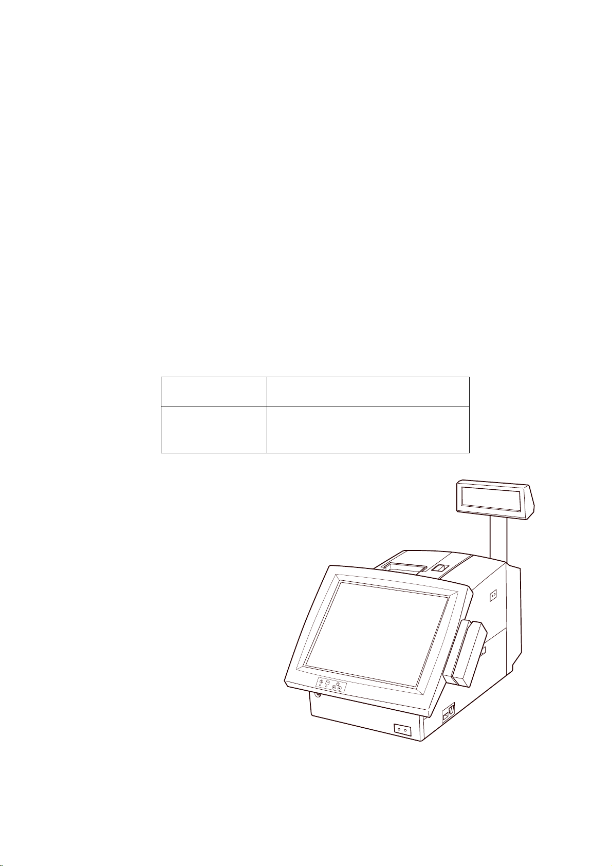
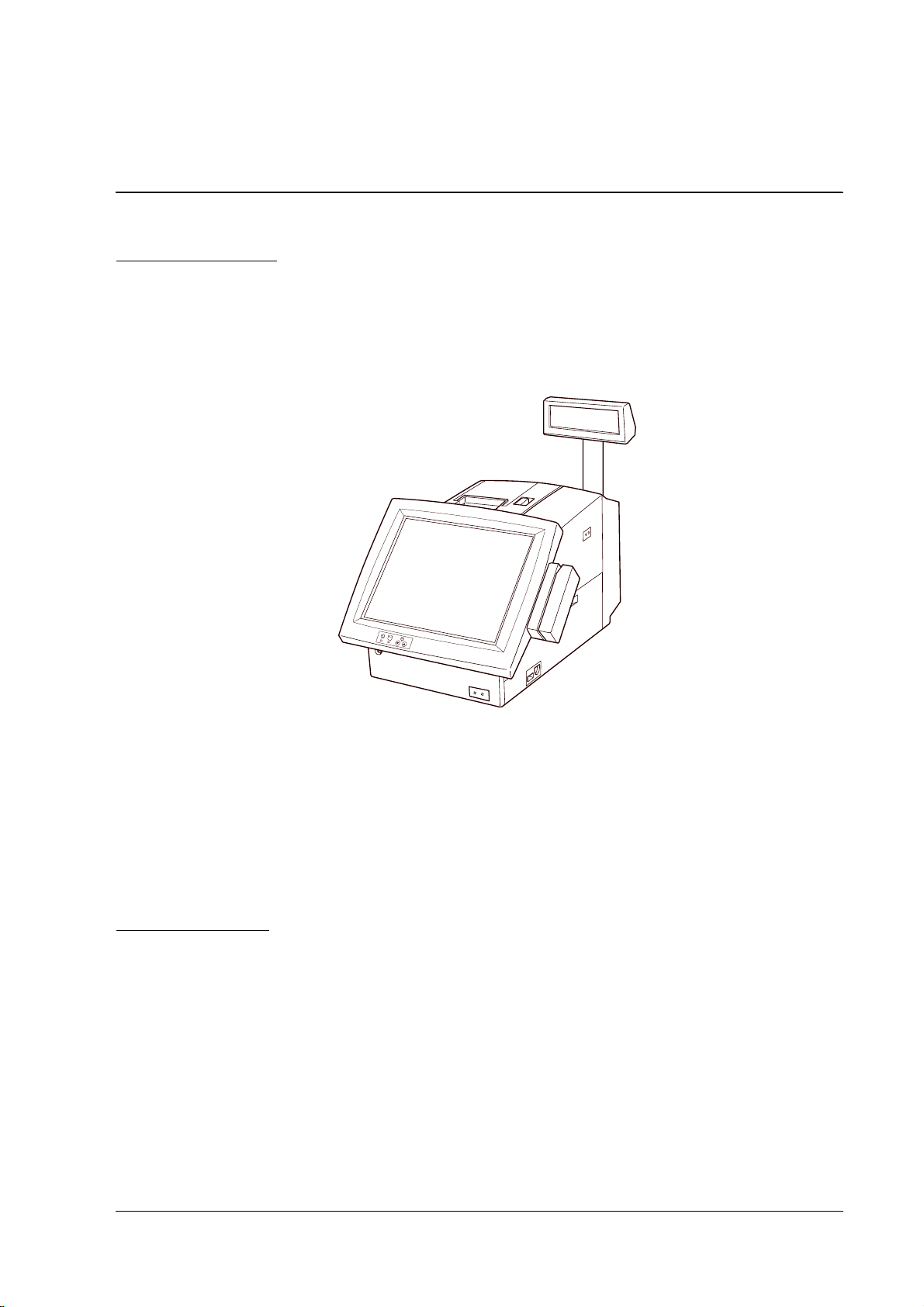
Part Names
The figures below show the part names of the IR-320.
IR-320 Technical Reference Manual
DM-LR121Series
eries LCD Display Unit
erieseries
lock lever
POWER LED
HDD LED
LCD brightness
adjustment buttons
Rev. D IR-320 System Overview 1-3
Page 20
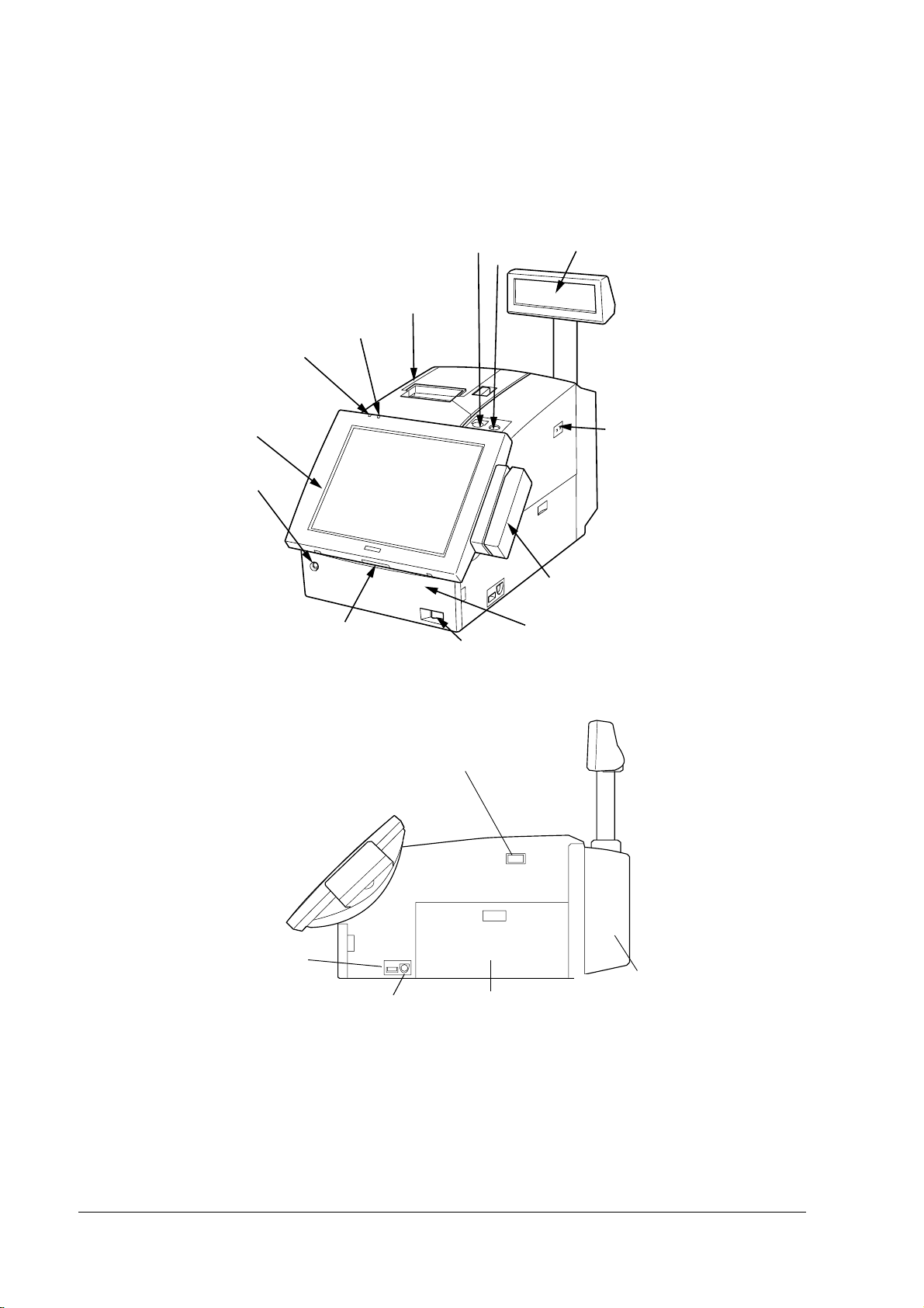
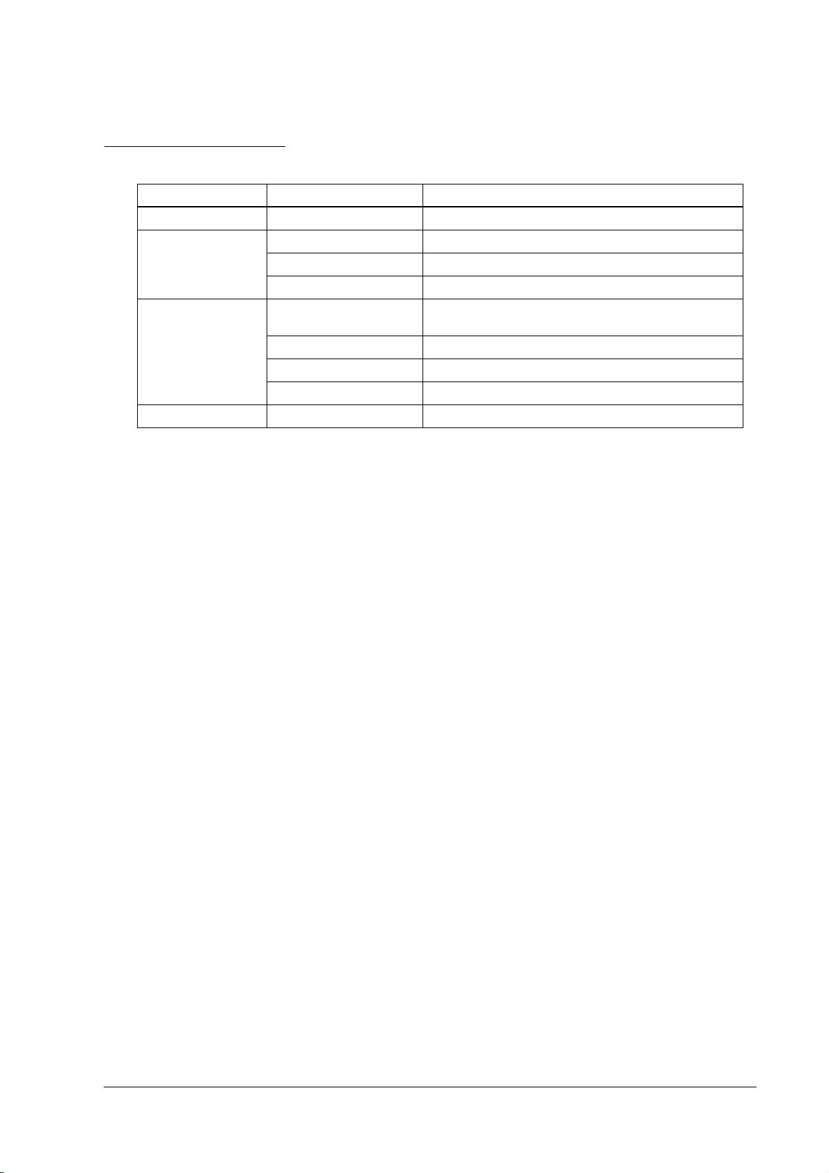
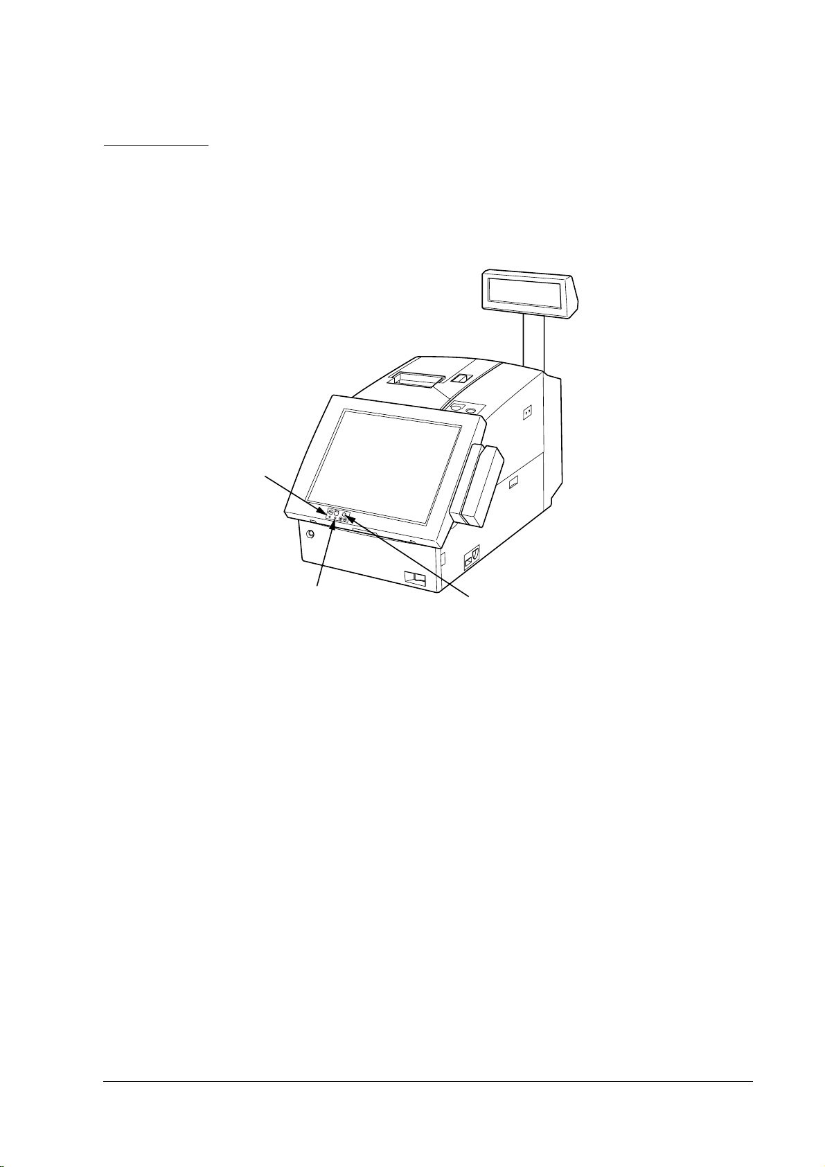
DM-LR104T LCD Display Unit
POWER LED
LCD unit (option)
front cover key lock
HDD LED
lock switch
paper FEED button
printer unit
(option)
soft power switch
customer display (option)
keylock
main power switch
MSR unit (option)
front cover
USB
keyboard/mouse
connector
main power switch
rear cover
side cover
1-4 IR-320 System Overview Rev. D
Page 21
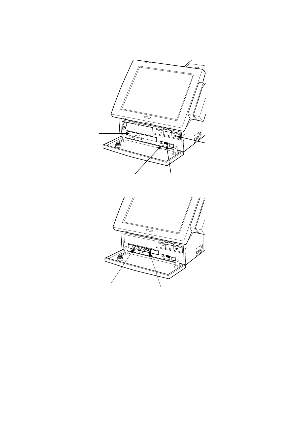
CD-ROM, CD-R/RW Drive (OI-R06)
CD-ROM,
CD-R/RW drive
reset switch volume
IR-320 Technical Reference Manual
Front CompactFlash Drive (OI-R07)
front CompactFlash adapter
eject button
Rev. D IR-320 System Overview 1-5
Page 22

Connector Names
The figures below show the connectors on the IR-320.
Fuse
AC inlet
AC outlet
Customer display
switch
Customer display
connector
TM power connector
Drawer kick connector
COM5 port
COM6 port
LPT port
COM2 port
COM1 port
Display connector
PCI slots
LAN LEDs
Ethernet connector
MIC
Line-In
Line-Out
USB connector
Main power switch
MSR
USB
KB/mouse
1-6 IR-320 System Overview Rev. D
Page 23

IR-320 Technical Reference Manual
Hardware Configurations
The IR-320 is an IBM® PS/2®-compatible system specifically designed for the POS environment.
The IR-320 has the following features:
❏ Intel Celeron processors are used. These high speed CPU processors offer the power and
speed needed for data processing.
❏ Two 168-pin DIMM sockets enable a maximum of 512MB RAM memory.
❏ One 88.9 mm {3.5"} HDD or two 63.5 mm {2.5"} HDDs can be installed internally.
❏ An optional CD-ROM drive , CD-R/RW drive or FrontCompactFlash adapter can be
installed internally.
❏ An Ethernet controller supports 10 BASE-T/100 BASE-TX.
❏ Contains two PCI slots.
❏ Compact size of 252 × 386 × 250 mm (W × D × H) {9.9 × 15.2 × 9.8"}(Without Rear Cover).
❏ An AC outlet (max. 3A) that is on whenever the system is on.
Model Configurations
The IR-320 can be configured with the following optional units:
❏ LCD units (with touch panel)
SVGA LCD unit (with touch panel)
264 mm {10.4"} color TFT Model name DM-LR104T
310 mm {12.2"} color TFT Model name DM-LR121SL *
310 mm {12.2"} color TFT Model name DM-LR121SV
❏ POS keyboard units
84-key Model name DM-KR084
28-key Model name DM-KR028
❏ Printer units
Thermal printer (58 mm, 80 mm {2.3", 3.2"}) Model name TM-T88IIIR
Serial dot impact printer Model name TM-U210AR **
Thermal receipt with slip Model name TM-H3000R
❏ MSR units
ISO/JIS I tracks 1, 2, and 3 Model name DM-MR123
❏ Customer display units
20 × 2-line display Model name DM-D110
20 × 2-line display Model name DM-D210
256 × 64 dots graphic display Model name DM-D500
❏ Battery unit (for IR-320/IR-310) Model name OI-R03-021
* For Europe, only project base.
** For Europe, not longer available.
Rev. D IR-320 System Overview 1-7
Page 24

❏ CD-ROM drive (for IR-320/ IR-310) Model name OI-R06-002
❏ CD-R/RW drive (for IR-320/ IR-310) Model name OI-R06-202
(An application that writes to the CD-R/RW must be added.)
❏ Front CompactFlash Adapter (for IR-320/IR-310)
Model name OI-R07
❏ Memory
256MB Model name OI-DIMM-256
128MB Model name OI-DIMM-128
❏ HDD
2.5" HDD Model name OI-HDD-300
3.5" HDD Model name OI-HDD
❏ TM printer tray
For TM-H6000 Model name OI-R01-022
For other TMs Model name OI-R01-001
❏ TM printer
Printer tray setting type Model name TM-U200 series
Model name TM-H6000 series
Model name TM-T88II series
❏ External mounting type Model name TM-U675 series
Model name TM-T285 series
Model name TM-H5000 series
Operation Testing Products for IR
The Operation Confirmed items are marketed by EPSON and are built-in, included, or
connected to an EPSON POS product, and operation by has been confirmed by EPSON. EPSON
can also offer reference information for the selection of peripheral devices to the customer who
constructs a system using EPSON POS products. Please inquire what kind of device can be used
from EPSON or the selling agent.
This operation confirmation evaluates the equipment in test environments and conditions, but it
does not guarantee the operation. Therefore, procurement and evaluation by the customer are
required.
1-8 IR-320 System Overview Rev. D
Page 25

IR-320 Technical Reference Manual
Software Configurations
BIOS Setup and Self-Diagnosis Functions
BIOS setup defines the system configuration. When the product is set up for the first time, run
this program to set the system environment. To change the operating environment, run this
program again. See Chapter 5, “BIOS Functions.”
Operating Systems
The IR-320 runs on the standard Microsoft operating systems: MS-DOS®, Windows® 98 Second
Edition, Windows NT
Professional.
Windows 2000 Professional, Windows NT Workstation 4.0 and Windows 98 Second Edition can
select the EPSON pre-installed HDD.
The IR-320 Driver CD-ROM that includes an appropriate driver for an operating system is
included.
See “OS Information” in Chapter 3.
Note:
The USB interface is not supported by Windows NT, and MS-DOS. (Windows NT supports the USB
Keyboard.)
Be sure to make the recovery media and back up the data. See ”Recovering the OS” in Chapter 3 for
details. When you need to repair the HDD, use the recovery disk.
®
WorkStation 4.0, Windows 2000 Professional and Windows XP
Utilities
Driver software and utilities software that operate and set peripherals are provided for the
IR-320.
Appropriate setting utility software is provided for each peripheral related to keyboard
firmware such as 28-key unit, MSR unit, and key lock.
Windows driver software is provided for the printer, customer display, and drawer. Contact
your dealer for the latest drivers and utilities information.
Rev. D IR-320 System Overview 1-9
Page 26

Operation Modes
The IR-320 has the following five operation modes.
(1) Mechanical Off Mode
In the mechanical off mode, the main power switch is off. No power is supplied to the IR-320
main body, and the power in all circuits is off.
To turn on the power to the IR-320, first turn on the main power switch.
(2) Soft Off Mode
In the soft off mode, only the main power switch is on. Items such as the clock circuit, backup
circuit, and power management circuit inside the IR-320 are on in the standby state. To save the
backup data after the power is off, the main power switch should remain on.
When the system is in the soft off mode, it can be put in full on mode by software, by pressing
the soft off switch, by a wake up signal from the LAN or by a ring signal from the modem.
(3) Full On Mode
In the full on mode, the main power switch and the soft power switch are on. The system is in
the normal operating state. Even if the system is started by a wake-up request signal from the
LAN, the full on mode is produced.
To turn off the IR-320 power, turn the power off from the software. The power-off operation
differs slightly, depending on the setting of the APM driver. See Chapter 4 “Utility“.
(4) Video Off Mode
When no input operation is performed for a given period of time during operation in the full on
mode, only the LCD and the backlight circuits are turned off, thus extending the service lifetime
for the LCD peripheral parts.
Depending on which operating system (OS) is used, the setup method for the time for transfer to
the video off mode differs. The setup method for each OS is described below.
Windows NT does not support the video off mode; therefore, the LCD and the backlight circuits
cannot be turned off during operation.
Type of OS Setup method for time of transfer to video off mode
Windows XP Set by [Power Options] property — [Turn off monitor]
Windows 2000 Set by [Power Options] property — [Turn off monitor]
Windows 98 Set by [Power Management] property — [Turn off monitor]
MS-DOS No setting
When “Power Button Tool“ is installed, Win 98 and Win 2K can realize “No-Operation“.
In the video off mode, the unit immediately returns to the full on mode when input is received
from the keyboard, mouse, or touch panel.
1-10 IR-320 System Overview Rev. D
Page 27
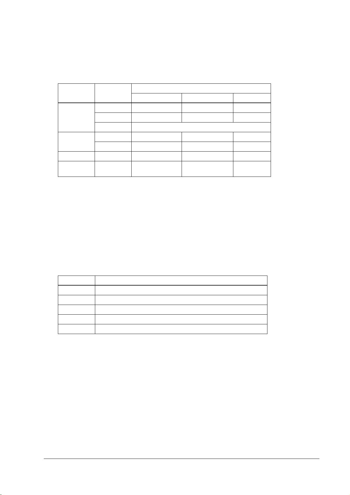
IR-320 Technical Reference Manual
Note that the reset operation differs, depending on the BIOS setting for the switch, when the soft
power switch is pressed during the video off mode.
BIOS [Soft-Off by PWR-BTTN] setting
Type of OS OS Setting
Windows XP Shutdown Full-on Full-on Shutdown
Standby Full-on Full-on Standby
Never No-Operation
Windows 2000 Shutdown Full-on Full-on Shutdown
Standby Full-on Full-on Standby
Windows 98 Standby Full-on Full-on Standby
MS-DOS Forced power off Reset to the full on
Instant-Off Delay 4 Sec. Disabled
mode
When “Power Button Tool“ is installed, Win 98 and Win 2K can realize “No-Operation“.
For Windows 2000, even if the soft power switch is pressed accidentally in the video off mode, it
stays in the video off mode.
(5) Suspend Mode
Turning off such items as the LCD, backlight circuit, and CPU when there is no input operation
for a specified time period in the full on mode extends the life of these parts.
In Windows 98, click Start, select Shut Down, and then select Standby in the Shut Down dialog.
In Windows NT, do not set up Suspend, because the system clock is delayed..
Type of OS Setup method for time of transfer to suspend mode
Windows XP Set with [Power Management] property — [ System Standby]
Windows 2000 Set with [Power Management] property — [ System Standby]
Windows NT Do not set up.
Windows 98 Set with [Power Management] property — [System Standby]
MS-DOS Set with BIOS [Suspend Timer]
In the suspend mode, the mode is immediately reset to the full on mode when input is received
from the keyboard, mouse, HDD,FDD or touch panel. Also, the suspend mode is always
changed to the full on mode when the soft power switch is pressed, regardless of the BIOS
switch setting.
Rev. D IR-320 System Overview 1-11
Page 28
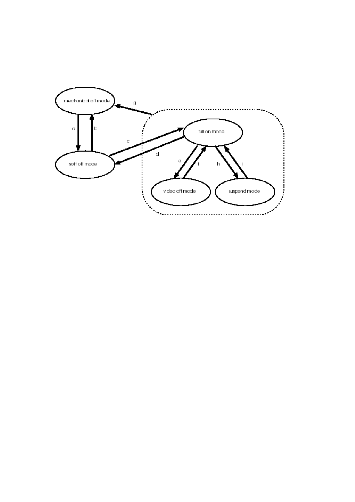
The status transition between each operation mode is as follows.
a. Main power switch on
b. Main power switch off or power off forced by AC power cutoff
c. Soft power switch on , wake-up request signal received from the LAN or ring signal from
the modem.
d. System shutdown by software (The operation differs, depending on the dedicated APM
driver setting. See Chapter 4 “Utility“.) and forced power off by pressing the soft power
switch (if the dedicated APM driver is used)
e. Transfer to the video off mode after no input operation for a specified period or selection of
video off mode at Operation System.
f. Input operation from keyboard, mouse, or touch panel
Reset by pressing the soft power switch (if the dedicated APM driver is used)
g. Main power switch off or forced power off because of AC power cutoff
h. Transfer to suspend mode because of no input operation for a specified period or selection
of suspend mode at Operation System.
i. Input operation from keyboard, mouse, or touch panel
Reset by pressing the soft power switch
1-12 IR-320 System Overview Rev. D
Page 29
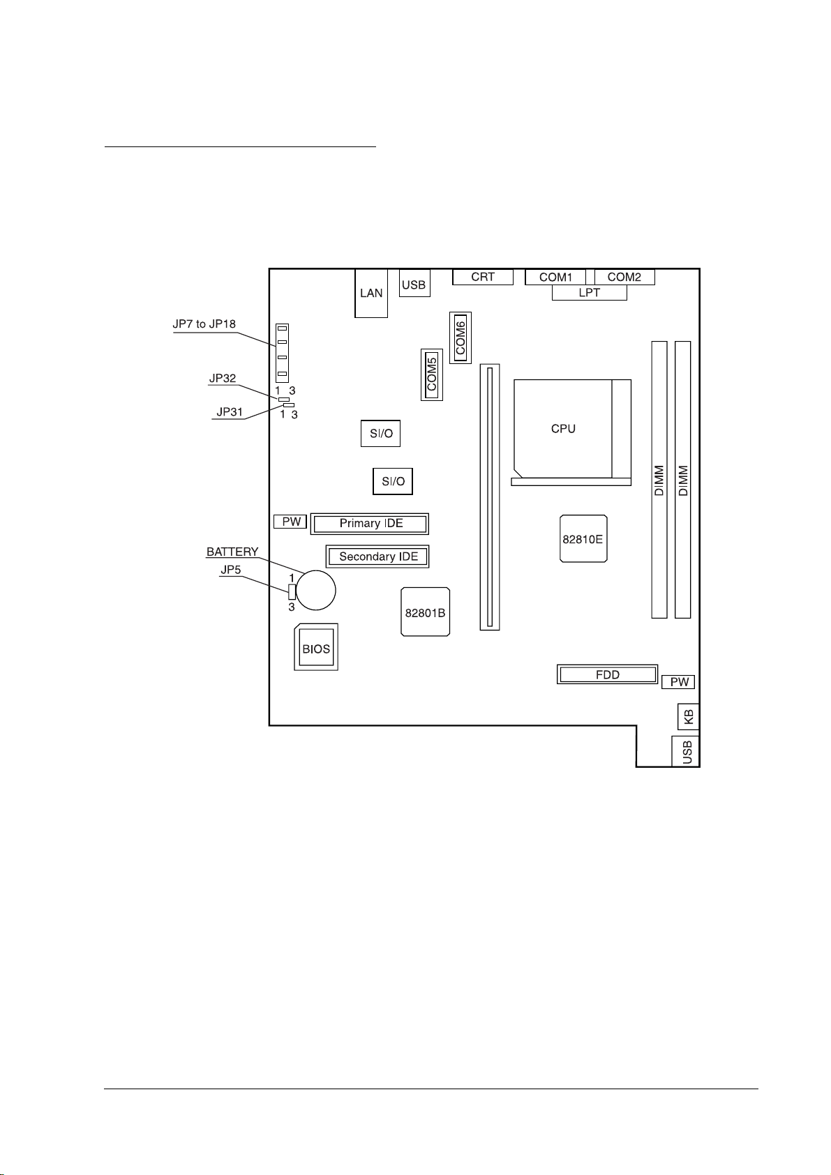
IR-320 Technical Reference Manual
Jumper Locations and Settings
Main Board Jumpers
The figure below shows the locations of the main board connectors and jumpers.
Rev. D IR-320 System Overview 1-13
Page 30
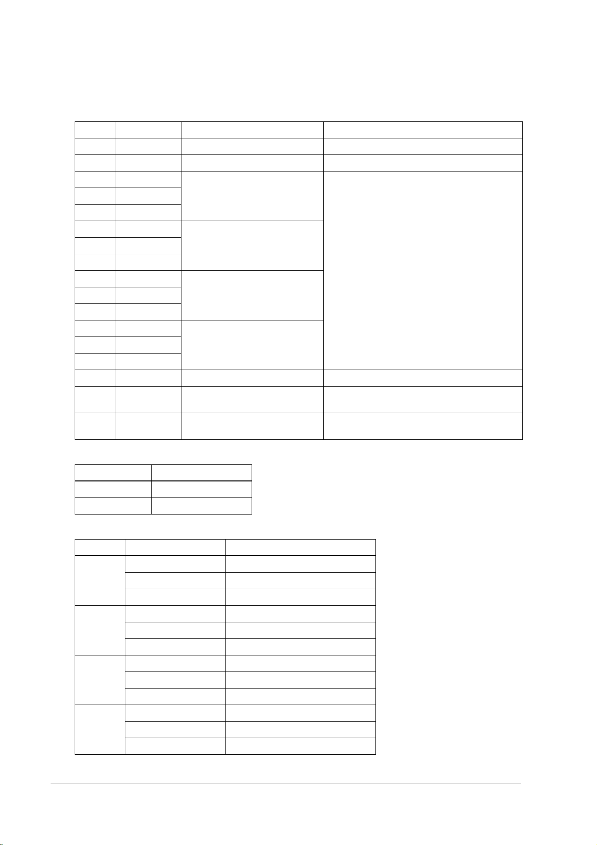
List of main board jumpers
Address Default setting Description Remarks
JP1 1-2 For system use Not changeable
JP5 1-2 Do not clear/clear RTC and CMOS See “JP5 settings (RTC and CMOS clear),” below
JP7 Short COM1 power output setting See “Settings for JP7 to 18 (COM1, COM2, COM5,
JP8 Open
JP9 Open
JP10 Short COM2 power output setting
JP11 Open
JP12 Open
JP13 Short COM5 power output setting
JP14 Open
JP15 Open
JP16 Short COM6 power output setting
JP17 Open
JP18 Open
JP 25 1-2 fixed For system use Not changeable
JP31 1-2 TM reset polarity setting See “JP31 settings (TM reset polarity settings)” on
JP32 1-2 TM/customer display flow control See “JP32 settings (TM/customer display flow
COM6 power output),” below
page 1-15
control)” on page 1-15
JP5 settings (RTC and CMOS clear)
JP5 RTC clear
1-2 (default) Normal operations
2-3 Clear
Settings for JP7 to 18 (COM1, COM2, COM5, COM6 power output)
Jumper short-circuited Pin 1 function in the DB9 connector
COM1 JP7 (Default) DCD signal
JP8 +5 V of electrical power
JP9 +12 V of electrical power
COM2 JP10 (Default) DCD signal
JP11 +5 V of electrical power
JP12 +12 V of electrical power
COM5 JP13 (Default) DCD signal
JP14 +5 V of electrical power
JP15 +12 V of electrical power
COM6 JP16 (Default) DCD signal
JP17 +5 V of electrical power
JP18 +12 V of electrical power
1-14 IR-320 System Overview Rev. D
Page 31

IR-320 Technical Reference Manual
JP31 settings (TM reset polarity settings)
JP31 Dedicated TM reset
1-2 (default) Active LOW
2-3 Active HIGH
This indicates the polarity of the signal when RTS or DTR is reset.
Set JP3 on the POS board when RTS or DTR is reset.
JP32 settings (TM/customer display flow control)
JP32 Dedicated TM flow control Customer display flow control Dedicated TM reset
1-2 RTS/CTS DSR DTR
2-3 (default) DTR/DSR CTS RTS
Set JP3 on the POS board when RTS or DTR is reset.
POS 320
320 Board Jumpers
320 320
The POS circuit board unit has two jumpers, one switch, and one four-polarity DIP switch that
can be set.
Parts Side (faces down when installing into the IR-320)
JP3
SW2
Back Side
DSW1
JP1
Rev. D IR-320 System Overview 1-15
Page 32

Functions of JP3 and DSW1
POS board
1
3
JP3
JP3: Use this jumper to make a TM printer reset using RTS or DTR effective.
DSW1:
Use this DIP switch to select the default value of the country mode of the MSR. And also use the
switch when the keyboard cannot be used due to a setting error.
41
ON
DSW1
The functions of the three jumpers and the DIP switch are shown below.
JP3 settings (TM reset enable/disable setting for RTS and DTR)
JP3 Dedicated TM reset
1-2 Reset enabled for RTS and DTR
2-3 (default) Reset disabled for RTS and DTR (reset only with RSTDRV)
DSW1 settings (DIP switch settings for keyboard controller)
SW Description
4 (default: OFF) Start-up mode (OFF: normal mode; ON: system boot)
SW1 SW2 SW3 Country
OFF OFF OFF US (Default)
ON OFF OFF Japan
OFF ON OFF France
ON ON OFF German
OFF OFF ON Spain
Up = Off; Down = On
Start-up mode
By switching to the enforced boot mode, it is possible to start up the system using the default
settings. This mode is designed for instances when start-up is impossible because of
overwriting of firmware and system variables. The enforced boot can be performed only
from an external keyboard. The MSR, 28-key keypad, and similar devices cannot be used.
Country setting
The country setting amends the default settings (such as MSR readers, K/B settings, and
28-key and 84-key default settings) when the settings are initialized and during an enforced
boot start-up.
1-16 IR-320 System Overview Rev. D
Page 33

Functions of SW2
IR-320 Technical Reference Manual
SW2
customer display connector
If you want to loop back the DTR and the DSR of the customer display port, set this switch to the
[1] side. This function might be needed when a system using a previous version of OPOS
controls a TM printer, without attaching a customer display.
Normally, set this switch to the [0] side.
Functions of SW2
Customer display loop-back jumper Dedicated TM reset
[1] side Loop back DTR and DSR.
[0] side (default) Normally used.
LCD setting jumper switch
The LCD setting jumper switch is located on the POS 320 board.
LCD setting jumper switch
LCD jumper switch settings
LCD setting jumper LCD units
1-2 DM-LR104T-252 / LR121SL / LR121SV
2-3 DM-LDM-LR104T-052
Rev. D IR-320 System Overview 1-17
Page 34

IR-320 Usage
See the IR-320 User’s Manual.
Dimensions
Main Body
252 mm {9.9"}
271 mm
{10.7"}
386 mm {15.2"}
454.5 mm {17.9"}
1-18 IR-320 System Overview Rev. D
Page 35

IR-320 Technical Reference Manual
}
Peripheral Dimensions of the LCD
329 mm {13.0"} - (DM-D500)
306 mm {12.1"} - (DM-D110)
541 mm {21.3"} - (DM-D500)
518 mm {20.4"} - (DM-D110)
454.5 mm {17.9"}
121Type:490mm{19.3"} /104Type:460 mm{18.1"}
121Type:555mm{21.9"} /104Type:521 mm {20.5"}
121Type:295mm{11.6”}/104Type:266 mm{10.5”}
121Type:317mm{12.5”} /104Type:297 mm{11.7”}
The 121 type is the case size of the DM-LR121Series, and the 104 type is the case size of the
DM-LR104T.
121Type:249mm{9.8"}/104Type:208 mm {8.2"}
121Type:273mm{10.8"}/104TYpe:234 mm {9.2"
121Type:310mm /104Type:276 mm
121Type:255mm /104Type:320 mm
121Type:425mm /104Type:390 mm
The 121 type is the case size of the DM-LR121Series, and the 104 type is the case size of the DMLR104T.
Rev. D IR-320 System Overview 1-19
Page 36

Peripheral Dimensions of the Customer Display
The dimensions in ( ) indicate the dimensions of the DP-504 with the extension prop.
DM-D500:83mm{3.3"}
DM-D110:69 mm{2.7"}
129 mm(DP-504) 227 mm
{5.1"} {8.9"}
Peripheral Dimensions of the Printer Tray
Dimensions when the OI-R101-001 is mounted.
178 mm {7.0"}
263 mm {10.4"}
1-20 IR-320 System Overview Rev. D
Page 37

IR-320 Technical Reference Manual
Dimensions when the dedicated printer TM-H6000 is attached to the OI-R01-022.
368 mm {14.5"}
40 mm {1.6"}
Dimensions When the Printer Unit is Mounted
TM-T88IIIR:262mm{10.3"}
TM-U210AR:283mm{11.1"}
TM-H3000R:327 mm {12.9"}
Rev. D IR-320 System Overview 1-21
Page 38

1-22 IR-320 System Overview Rev. D
Page 39

Confidential
IR-320 Technical Reference Manual
Chapter 2
Setup
This chapter explains how to set up options and peripheral units of the IR-320.
Overview of the setup
The peripherals of the IR-320 include the ones that are set by a driver or a utility at the time of
setup and must confirm in the operation. Peripherals may not operate correctly if the installation
order of OS and driver is not correct.
The basic flow of the setup is described below.
Printer/Customer display
/Cash drawer
Installing OS Installing OS
Installing the dedicated
customer
drawer and so on.
Operating confirmation with
Device Diagnostics Utility
display, the cash
28/84-Keyboard/MSR/ KeyLock
Installing the 28/84-Keyboard/ MSR
Setting the keyboard firmware
with the keyboard firmware
setting utility./Making the
definition data file.
Setting to define automatically
for more than one system
The setup completion
Rev. D Setup 2-1
Page 40

Confidential
Battery
Attaaching the battery unit
Installing OS
Setting the BIOS
Installing the APM driver
(only Windows NT)
Installing the Power Button
tool (for Windows 98/2000)
Installing the AC line tool
(for Windows 2000/XP)
Required
Optional
The setup completion
Refer to each item about the other peripheral devices and options.
Precautions for Setting Up
In addition to the precautions below, warning instructions and cautions to note are given at each
work stage.
CAUTION:
❏ Turn off the power for all equipment, including the IR-320 and all peripherals, before
setup. Turn off the main (side) power switch for the IR-320. Unplug the power cables
for the IR-320 and its peripheral units from the outlet. If the power is not turned off, the
IR-320 or peripheral units may be damaged during setup.
❏ When the battery unit is installed and the power is on, do not turn off the main (side)
power switch or unplug the power cable until you put the IR-320 in the soft off mode
with the soft (front)
unplug the power cable. If the main power switch is turned off or the power cable is
unplugged when the unit is in full on mode, power starts flowing from the battery
unit. If power starts flowing from the battery unit, turn ON the main power switch,
which stops the power supply from the battery unit.
power switch. Then you can turn off the main power switch and
2-2 Setup Rev. D
Page 41

Confidential
❏ Static electricity can damage the components of the IR-320. Before you touch any
components, touch a grounded metal surface to discharge the static electricity in
your body. It is also recommended that you wear a grounded wristband and work
on an antistatic surface.
❏ Do not touch the connectors. Dirt may cause a malfunction.
❏ Do not apply excessive force to connectors, cables, or screws during connection.
Excessive force may damage the connectors or the screw threads.
❏ Do not allow cables to be pinched. The cables may be damaged or disconnected.
IR-320 Technical Reference Manual
Operations Before Setting Up the IR-320
Before setting up the IR-320, complete the following operations:
1. If Windows is running, exit it. The resulting power off condition is called “soft off.” Proceed
to step 4.
2. Press the soft (front) power switch once and let go. The resulting power off condition is also
called “soft off.” Proceed to step 4. If the power does not go off, proceed to step 4.
3. Press the soft power switch again, and hold it down for 4 seconds or more. The power
supply to the IR-320 will go off.
4. Turn off the main (side) power switch. The resulting power off condition is called
“mechanical off.”
5. When the battery unit is attached, remove it.
6. Unplug the power cable. Confirm that power supplies to all peripheral units are off and
unplug the connection cables from them.
Operation Testing Products
The operation confirmation products are the ones that are built-in, included, or connected to
EPSON POS products, and their operation has been confirmed by EPSON. EPSON can offer
reference information for the selection of peripheral devices to the customer who constructs a
system using an EPSON POS product. Please ask EPSON or the selling agent what kind of
device can be used.
This operation confirmation evaluates the operation of the products in a usual environment, but
does not guarantee the operation. Therefore, the customer is basically responsible for the
procurement and the evaluation of the equipment.
Rev. D Setup 2-3
Page 42

Confidential
How to Install Options/Peripheral Units
See the following pages for instructions on setting up each option or peripheral.
Option/Peripheral Page
Installing a DIMM (Memory) 2-5
Installing a 2.5" HDD Unit (OI-HDD) *1 2-7
Installing a 3.5" HDD Unit (OI-HDD) *1 2-11
Installing a CD-ROM Drive , CD-R/RW Drive (OI-R06)*2 2-17
Installing a Front CompactFlash Card Adapter (OI-R07)*2 2-21
Installing an LCD Unit 2-24
Installing an 84-Key Keyboard Unit (DM-KR084) (DM-KR084) 2-35
Installing a Battery Unit (OI-R03) 2-39
Installing a 28-Key Keyboard Unit (DM-K028) 2-43
Installing the MSR Unit (DM-MR123) 2-48
Installing a Printer Tray 2-52
Installing a Printer 2-54
Installing a PCI Board 2-60
Installing a Customer Display 2-62
Installing a Mouse/Keyboard 2-67
Installing a Cash Drawer 2-68
Attaching a Power Cable 2-69
*1: The 2.5" HDD unit (OI-HDD) and the 3.5" HDD unit (OI-HDD) cannot be installed together.
*2: The CD-ROM drive (OI-R06) and the front CompactFlash adapter (OI-R07) cannot be installed together.
Note:
Don’t use a serial mouse.
2-4 Setup Rev. D
Page 43

Confidential
IR-320 Technical Reference Manual
Installing a DIMM (Memory)
DIMMs (memory) are installed in the DIMM sockets on the main board.
One 128MB DIMM is standard on the IR-320. Two DIMM sockets (168-pin type), which can
increase the memory to 512MB, are available. Remove the DIMM originally installed, and install
the two DIMMs instead.
CAUTION:
❏ Static electricity can damage the components of the IR-320. Before you touch any
components, touch a grounded metal surface to discharge the static electricity in
your body. It is also recommended that you wear a grounded wristband and work
on an antistatic surface.
❏ Do not touch the DIMM connectors. Dirt may cause a malfunction.
❏ If it is difficult to insert the DIMM, do not apply excessive force to the DIMM. If
excessive force is used, the connection parts may be damaged. Remove the DIMM,
check the connection part to confirm that no problem exists, and then insert it
again.
The DIMM is installed by using the following procedure:
1. Slide the right side cover down until it comes off.
2. Remove the two screws from the side panel, and remove the side panel by pulling it out
while lifting it.
Rev. D Setup 2-5
Page 44

Confidential
3. Match the two notches in the DIMM to the projections on the socket, and push the DIMM
until it clicks and stands upright.
Note:
When two DIMMs are installed, use the farthest socket first.
4. Reattach the side panel with two screws.
5. Reattach the side cover.
Removing the DIMM
To remove the DIMM, unlock the lock pins located on both sides of the DIMM socket, and pull
the DIMM straight up.
2-6 Setup Rev. D
Page 45

Confidential
IR-320 Technical Reference Manual
Installing a 2.5" HDD Unit (OI-HDD)
The IR-320 has one or two 2.5" HDDs or one 3.5" HDD, according to its specifications. Up to two
2.5" HDDs can be installed.
For information on installing the 3.5" HDD unit (OI-HDD), see the following section, “Installing
a 3.5" HDD Unit (OI-HDD).”
To install a 2.5" HDD, remove the HDD unit currently installed in the IR-320, install the optional
HDD, and reinstall original the HDD unit in the IR-320. Install the optional HDD using the
following procedure.
CAUTION:
Don’t write anything, such as an application to an HDD that is removed from the IR-320.
The vibration and impact can cause trouble and the failure of the HDD.
Do not subject the HDD unit to shock or vibration. Because the HDD unit is a precision
instrument, do not subject it to even the slightest shock or vibration.
(1) Removing the HDD unit
1. Open the front cover of the IR-320. If the front cover is locked, unlock it with the front key.
To unlock the front cover, insert the key into the front lock, and push in slightly while you
turn it.
front cover
2. Open the HDD cover by lightly pressing down on the upper pin lock.
Rev. D Setup 2-7
Page 46

Confidential
3. Remove the two screws from the HDD unit.
4. Pull the HDD unit toward the front slightly while watching the cables, and remove the two
cables for the HDD unit from the their connectors.
5. Remove the HDD unit.
6. Remove the four screws from the HDD unit, and remove the HDD plate.
HDD plate
2-8 Setup Rev. D
Page 47

Confidential
7. When removing the HDD drive, remove the four screws for the HDD drive as shown in the
figure below, and remove it.
removing the HDD in the lower drive bay removing the HDD in the upper drive bay
IR-320 Technical Reference Manual
(2) Installing the HDD
1. Install the HDD in the HDD unit, and attach it with four screws.
installing the HDD in the lower drive bay installing the HDD in the upper drive bay
2. When you use two HDDs, set the jumpers to make one a “master” and the other a “slave.”
To make an HDD a master drive, remove the jumper. To make an HDD a slave, set the
jumper.
Note:
When you use two drives, one must be a master and one must be a slave. The IR-320 will not boot
from the slave drive.
An HDD may be set to either a master or slave, whether it is installed in the upper drive bay or the
lower drive bay.
Rev. D Setup 2-9
Page 48

Confidential
3. Attach the HDD plate with four screws.
HDD plate
(3) Installing the HDD unit
Install the HDD unit using the steps below. If you are installing the HDD where the cables will
be hidden, as shown in step 3 of “Removing the HDD unit,” use the steps for “Installing the
HDD unit where the cables will be hidden” later in this section.
1. Push the HDD unit into the IR-320 from the front. Be careful not to subject the HDD to shock
or vibration, and be sure the cables are not pinched. Confirm that the projection on the
mounting plate under the HDD is firmly engaged with the frame projection on the IR-320.
projection on HDD mounting plate
frame projection
2. Connect the two cables for the HDD unit to their connectors.
2-10 Setup Rev. D
Page 49

Confidential
3. Lock the HDD unit with two screws.
4. Reattach the HDD cover.
5. Close the front cover.
6. Turn on the IR-320, start up the BIOS setup, and confirm that the HDD is normally
identified. For information on the BIOS setup, see Chapter 5, “BIOS Functions.”
IR-320 Technical Reference Manual
Installing a 3.5" HDD Unit (OI-HDD)
The IR-320 has one or two 2.5" HDDs or one 3.5" HDD, depending on its specifications. Up to
two 2.5" HDDs can be installed.
For information on installing the 2.5" HDD units (OI-HDD), see the previous section, “Installing
a 2.5" HDD Unit (OI-HDD).”
The IR-320 does not start up though the battery unit (OI-R03) as the option is connected to the
IR-320.
To install the 3.5" HDD, remove the currently installed HDD unit from the IR-320, install the
optional HDD in the HDD unit, and reinstall the HDD drive bay in the IR-320.
Install the optional HDD using the following procedure.
CAUTION:
Don’t write anything, such as an application to an HDD that is removed from the IR-320.
The vibration and impact can cause trouble and the failure of the HDD.
Do not subject the HDD unit to shock or vibration. Because the HDD unit is a precision
instrument, do not subject it to even the slightest shock or vibration.
Rev. D Setup 2-11
Page 50

Confidential
(1) Removing the HDD unit
1. Open the front cover of the IR-320. If the front cover is locked, unlock it with the key. (You
may need to press in slightly as you turn the key.)
front cover
2. Open the HDD cover by lightly pressing down on the upper pin lock.
3. Unscrew two screws and remove the HDD faceplate.
2-12 Setup Rev. D
Page 51

Confidential
4. Remove the left side cover by sliding it downward.
5. Remove the two screws attaching the side panel.
IR-320 Technical Reference Manual
6. If a PCI card is installed, remove it. Remove the screw locking the PCI card and pull the PCI
card out.
Rev. D Setup 2-13
Page 52

Confidential
7. Remove the two cables for the HDD unit from their connectors.
8. Remove the HDD unit from the front while watching the cables.
9. Remove the two cables from the HDD unit.
10. Remove the four screws from the HDD unit, and remove the HDD mounting plate.
2-14 Setup Rev. D
Page 53

Confidential
(2) Installing the HDD
Install the HDD using the following procedure:
1. Attach the HDD to the HDD mounting plate with four screws.
2. Set the HDD jumper as shown in the below figure.
The jumper setting depends on the make and model of the HDD. Set the jumper for your
HDD.
IR-320 Technical Reference Manual
3. Connect the two cables to their connectors.
Rev. D Setup 2-15
Page 54

Confidential
D
(3) Installing the HDD unit
1. Slide the HDD unit into the IR-320 from the front, being careful not to subject it to shock or
vibration, and be sure the cables are not pinched. Confirm that the projection on the
mounting plate under the HDD is firmly engaged with the frame projection on the IR-320.
projection on the HD
mounting plate
frame projection
2. Connect the two cables for the HDD unit to their connectors.
2-16 Setup Rev. D
Page 55

Confidential
3. Lock the HDD unit with two screws.
4. Reattach the HDD cover.
5. Insert the removed PCI card.
IR-320 Technical Reference Manual
6. Reattach the side panel with two screws.
7. Reattach the side cover.
8. Close the front cover.
9. Turn on the IR-320, start up the BIOS setup, and confirm that the HDD is identified
normally. For information on the BIOS setup, see Chapter 5, “BIOS Functions.”
Installing a CD-ROM Drive , CD-R/RW Drive (OI-R06)
The optional 24× CD-ROM drive (OI-R06) or CD-R/RW drive (OI-R06-202) is installed using the
following procedure:
Note:
The CD-R/RW drive can write, but you must prepare the application to write.
Rev. D Setup 2-17
Page 56

Confidential
CAUTION:
Because the CD-ROM, CD-R/RW drive is a precision instrument, do not subject it to even
the slightest shock or vibration; otherwise, the CD-ROM, CD-R/RW drive may stop
operating.
Install the CD-ROM, CD-R/RW drive by following the steps below.
1. Open the front cover of the IR-320. If the front cover is locked, unlock it with the key. (You
may need to press in slightly as you turn the key.)
front cover
2. Remove the HDD cover.
3. Remove the CD-ROM cover. (Keep this cover because it is not used while the CD-ROM, CDR/RW drive is installed.)
2-18 Setup Rev. D
Page 57

Confidential
4. Remove the left side cover by sliding it downward.
5. Remove two screws attaching the side panel.
IR-320 Technical Reference Manual
6. Attach the cable set to the CD-ROM, CD-R/RW drive.
Rev. D Setup 2-19
Page 58

Confidential
7. Push the CD-ROM, CD-R/RW drive into the IR-320 from the front, being careful not to
subject it to shock or vibration, and be sure the cables are not pinched. Confirm that the
projection under the CD-ROM, CD-R/RW drive is firmly engaged with the frame projection
on the IR-320. If the cable for the HDD unit is in the way of the connection for the CD-ROM,
CD-R/RW drive, remove the HDD unit cable, connect the cable for the CD-ROM, CD-R/RW
drive, and re-connect the HDD unit cable.
projection under the
CD-ROM, CD-R/RW drive
frame projection
8. Connect the cable for the CD-ROM, CD-R/RW drive to the connector.
9. Attach the CD-ROM, CD-R/RW drive with one screw.
screw hole
10. Reattach the HDD cover.
11. Reattach the side panel with two screws.
2-20 Setup Rev. D
Page 59

Confidential
12. Reattach the side cover.
13. Close the front panel.
IR-320 Technical Reference Manual
Installing a Front CompactFlash Card Adapter (OI-R07)
CAUTION:
The front CompactFlash card adapter is precise equipment; so handle it gently. When
you remove and install the front CompactFlash card adapter. be careful not to subject
it to small shock, vibration or bending, because this may damage it.
Card type One Type I or Type II
Power supply +3.3 V/50 mA (max.)
I/F mode True IDE mode
Connection to the main body Secondary IDE bus (master) connection
1. Open the front cover of the IR-320. If the front cover is locked, unlock it with the key. (You
may need to press in slightly as you turn the key.)
front cover
Rev. D Setup 2-21
Page 60

Confidential
2. Remove the HDD cover.
3. Remove the CD-ROM cover. (Keep this cover because it is not used while the front
CompactFlash card adapter is installed.)
4. Remove the left side cover by sliding it downward.
5. Remove two screws attaching the side panel.
2-22 Setup Rev. D
Page 61

Confidential
6. Push the front CompactFlash card adapter into the IR-320 from the front, being careful not to
subject it to shock or vibration, and be sure the cables are not pinched. Confirm that the
projection under the front CompactFlash card adapter is firmly engaged with the frame
projection on the IR-320. If the cable for the HDD unit is in the way of the connection for the
front CompactFlash card adapter, remove the HDD unit cable, connect the cable for the front
CompactFlash card adapter, and re-connect the HDD unit cable.
IR-320 Technical Reference Manual
projection under the front
CompactFlash card adapter
frame projection
7. Attach the front CompactFlash card adapter with one screw.
8. Connect the cable for the front CompactFlash card adapter to the connector.
9. Reattach the HDD cover.
10. Reattach the side panel with two screws.
Rev. D Setup 2-23
Page 62

Confidential
11. Reattach the side cover.
12. Close the front panel.
Installing an LCD Unit
Three LCD units are available:
LCD unit Type Display size Resolution
DM-LR104T TFT 10.4" {26.42 cm} SVGA 800x600
DM-LR121SL TFT 12.1" {30.73 cm} SVGA 800x600
DM-LR121SV TFT 12.1" {30.73 cm} SVGA 800x600
The 84-keyboard (DM-KR084) can be installed instead of an LCD unit.
DM-LR121Series
DM-LR104T
❏ Attach the ferrite core (an accessory of the IR-320) to the appointed cable.
❏ Select the touch panel driver from the type of the LCD unit, and install when the OS is
installed.
Note:
When you connect another type of the LCD unit, you need to install another touch panel driver. For
details, ask your dealer.
Description of jumper switch for each LCD unit
LCD unit Jumper switch
DM-LR104T-052 2-3
DM-LR104T-252 1-2
DM-LR121SL 1-2
DM-LR121SV 1-2
2-24 Setup Rev. D
Page 63

Confidential
DM-LR121Series
1 Remove the left side cover by sliding it downward.
2 Remove the two screws from the printer unit or the printer tray.
IR-320 Technical Reference Manual
3 Remove the printer unit or the printer tray. When removing the printer unit, remove the
printer cable from the connector.
4 Thread the two cables for the LCD unit through the hole in the center of the IR-320.
Rev. D Setup 2-25
Page 64

Confidential
5 Engage the right and left tabs on the IR-320 with the right and left grooves in the back of the
LCD unit. When both sides are engaged, slide the LCD unit down while pressing the lock
lever on the left side of the LCD unit.
groove in the LCD unit
tab on the IR-320
6 The LCD unit has a 34-pin connector cable and a 38-pin connector cable. Attach the ferrite
core (an accessory of the IR-320) to the 34-pin connector cable.
7 Connect the cables for the LCD unit to their connectors.
layout of the connectors
CN51
CN35(34-pin)
Jumper Switch
CN31(38-pin)
JP1
POS board
8 Check the Jumper Switch setting. For the DM-LR121SV/DM-LR121SL, set the JP1 to “1-2.”
9 Install the printer unit or the printer tray, and lock it with two screws.
10 Reattach the side cover.
2-26 Setup Rev. D
Page 65

Confidential
DM-LR104T
1. Remove the left side cover by sliding it downward.
2. Remove the two screws from the printer unit or the printer tray.
IR-320 Technical Reference Manual
3. Remove the printer unit or the printer tray. When removing the printer unit, remove the
printer cable from the connector.
4. Set the lock knob under the LCD unit to the release position.
Rev. D Setup 2-27
Page 66

Confidential
5. Thread the two cables for the LCD unit through the hole in the center of the IR-320.
6. Engage the right and left tabs on the IR-320 with the right and left grooves in the back of the
LCD unit. When both sides are engaged, slide the LCD unit down on the back.
groove in the LCD unit
tab on the IR-320
7. The LCD unit has a 34-pin connector cable and a 38-pin connector cable. Attach the ferrite
core (an accessory of the IR-320) to the 34-pin connector cable.
ferrite core
2-28 Setup Rev. D
Page 67

Confidential
8. Connect the cables for the LCD unit to the connectors.
IR-320 Technical Reference Manual
layout of the connectors
CN51
CN35(34-pin)
Jumper Switch
CN31(38-pin)
JP1
POS board
9. Check the Jumper Switch setting. For the DM-LR104T-252, set the JP1 to “1-2,” and for the
DM-LR104T-052, set the JP1 to “2-3.”
Note:
If the jumper is incorrectly set, the LCD display is not correct.
10. Return the lock knob under the LCD unit to the lock position.
11. Install the printer unit or the printer tray, and lock it with two screws.
12. Reattach the side cover.
Rev. D Setup 2-29
Page 68

Confidential
Removing the LCD Unit
The removal procedure for the LCD depends on the type of LCD unit.
DM-LR121Series
1. Remove the left side cover by sliding it downward.
2. Remove the two screws from the printer unit or the printer tray.
3. Remove the printer unit or the printer tray. When removing the printer unit, remove the
printer cable from the connector.
printer cable
2-30 Setup Rev. D
Page 69

Confidential
4. Remove the two cables for the LCD unit from their connectors.
5. Remove the ferrite core. Keep the removed ferrite core for installing on another LCD unit.
IR-320 Technical Reference Manual
Rev. D Setup 2-31
Page 70

Confidential
6. Slide the LCD unit until it hits the upper limit of the slide range while pressing the lock lever
on the left side of the LCD unit.
Slightly pull the part circled in the illustration below in the direction of the arrow, and slide
the LCD unit upward further on the back.
Adjust the position of the LCD unit while watching the hole shown in the figure so that the
tabs of the main body can be disengaged from the grooves in the LCD unit.
Remove the LCD unit in the direction of arrow (5).
DM-LR104T
1. Remove the left side cover by sliding it downward.
2. Remove the two screws from the printer unit or the printer tray.
2-32 Setup Rev. D
Page 71

Confidential
3. Remove the printer unit or the printer tray. When removing the printer unit, remove the
printer cable from the connector.
4. Remove the two cables for the LCD unit from their respective connectors.
IR-320 Technical Reference Manual
5. Remove the ferrite core. Keep the removed ferrite core for installing on another LCD unit.
Rev. D Setup 2-33
Page 72

Confidential
6. Slide the lock located under the LCD unit to the right for unlocking.
7. Slide the LCD unit until it hits the upper limit of the slide range.
Slightly pull the part circled in the illustration below in the direction of the arrow, and slide
the LCD unit upward further on the back.
Adjust the position of the LCD unit while watching the hole shown in the illustration below
so that the tabs of the main body can be disengaged from the grooves in the LCD unit.
Remove the LCD unit in the direction of arrow (4).
2-34 Setup Rev. D
Page 73

Confidential
IR-320 Technical Reference Manual
Installing an 84-Key Keyboard Unit (DM-KR084)
The 84-key keyboard can be installed instead of the LCD unit. The 84-key keyboard is installed
by using the following procedure.
1. Remove the left side cover by sliding it downward.
2. Remove the two screws from the printer unit or the printer tray.
3. Remove the printer unit or the printer tray. When removing the printer unit, remove the
printer cable from the connector.
4. Set the lock knob under the 84-key keyboard to the release position.
Rev. D Setup 2-35
Page 74

Confidential
5. Thread one cable of the 84-key keyboard through the hole in the center of the IR-320.
6. Engage the right and left grooves on the back of the keyboard with the right and left tabs on
the IR-320. When both sides are engaged, slide the LCD unit down on the back for
installation.
groove of the 84-key
tab on the IR-320
keyboard
7. Connect the 38-pin connector cable for the 84-key keyboard to connector CN31.
layout of the connectors
CN51
CN35(34-pin)
Jumper Switch
CN31(38-pin)
JP1
POS board
8. Set the Jumper Switch(JP1) to “1-2.”
9. Return the lock knob under the 84-key keyboard to the lock position.
2-36 Setup Rev. D
Page 75

Confidential
10. Install the printer unit or the printer tray, and lock it with two screws.
11. Reattach the side cover.
Removing an 84-Key Keyboard Unit
1. Remove the left side cover by sliding it downward.
IR-320 Technical Reference Manual
2. Remove the two screws from the printer unit or the printer tray.
3. Remove the printer unit or the printer tray. When removing the printer unit, remove the
printer cable from the connector.
printer cable
Rev. D Setup 2-37
Page 76

Confidential
4. Remove one cable for the 84-key keyboard from the connector, as shown below.
5. Slide the lock under the 84-key keyboard to the right to unlock it.
6. Slide the 84-key keyboard until it hits the upper limit of the slide range.
Slightly pull the part circled in the illustration below in the direction of the arrow, and slide
the LCD unit upward further on the back side.
2-38 Setup Rev. D
Page 77

Confidential
Adjust the position of the 84-key keyboard while watching the hole shown in the figure so
that the tabs on the main body can be disengaged from the grooves in the 84-key keyboard.
Pull the 84-key keyboard out.
IR-320 Technical Reference Manual
Installing a Battery Unit (OI-R03)
The nickel-cadmium battery unit (OI-R03) backs up operations automatically if the power turns
off abruptly, such as in the case of a power interruption.
The specifications for the battery unit are as follows:
Type: Ni-Cd 8-cell, 600 mAh
Charging time: About 32 hours
Charging method: Trickle
The charging and backup times change according to environmental conditions.
To use the battery unit, install the dedicated Power Management Driver APM2.0 supplied with
the battery unit. (for Windows NT)
Rev. D Setup 2-39
Page 78

Confidential
The battery unit begins to be charged when the IR-320 main (side) power switch is turned on.
After installing a battery unit, set System Battery to Equipped using the Power
Management menu in the BIOS setup utility. (See Chapter 6.)
Note (for Users in the United States):
The battery unit (OI-R03) is powered by a nickel-cadmium battery, which is recyclable. At the end of its
useful life, it is illegal under various state and local laws to dispose of this battery into the municipal waste
stream. Call 1-600-8-BATTERY for information on how to recycle this battery.
Note:
The battery unit is not charged even if power is being supplied and the main power switch is on unless the
power is in full on mode.
The battery unit cannot be used for the IR-320 connected with the 3.5” HDD.
The battery unit has not yet been charged when it is purchased. Charge the battery unit before using it.
The nickel-cadmium battery must be recycled or disposed of properly.
The life of the battery unit is approximately 2 to 2.5 years. Replace the battery unit accordingly.
Install the battery unit following the steps below.
1. Remove the left side cover by sliding it downward.
2-40 Setup Rev. D
Page 79

Confidential
2. Remove the two screws from the printer unit or the printer tray.
3. Remove the printer unit or the printer tray. When removing the printer unit, remove the
printer cable from the connector.
IR-320 Technical Reference Manual
printer cable
4. Set the battery unit in the battery unit box. Pull the tab of the battery box up, and insert the
battery unit into the battery box.
Rev. D Setup 2-41
Page 80

Confidential
5. Connect the cable of the battery unit as shown below.
6. Reattach the printer unit or the printer tray using two screws.
7. Reattach the side cover.
Setting the BIOS
After the battery unit is installed, change the BIOS setting by using the following procedure:
1. When an external keyboard is not connected to the IR-320, connect the external keyboard to
the mouse/keyboard connector.
2. Turn on the power supply to the IR-320.
3. While the following message is on the display, press Del:
Press DEL to enter SET UP.
4. The BIOS setup utility starts up.
5. Select Power Management Setup using the cursor keys and press Enter. The Power
Management Setup menu appears.
6. Select System Battery and change the setting to Equipped.
7. After completion of the setting, press Esc. The main menu resumes.
8. Select Save & Ex it Setup using the cursor keys, and press Enter. A dialog appears. Press
Y and then Enter.
Installing a dedicated AC Line tool (Windows 2000/98)
The AC Line Tool is used to send a notification to the application that the system power has
been changed from the AC Line to the battery drive in Windows 2000/98.
Installing a dedicated APM driver (Windows NT Only)
When using the battery unit with Windows NT, install the dedicated APM driver included with
the battery unit.
❏ Power Management Driver APM2.0 for Windows NT
Refer to “Chapter 4 Utilities” for the installation procedure.
2-42 Setup Rev. D
Page 81

Confidential
IR-320 Technical Reference Manual
Installing a 28-Key Keyboard Unit (DM-K028)
The 28-Key Keyboard unit is an optional input device for the IR-320. It has 28 keys in total, 4
columns by 7 lines. The function of each key can be freely assigned by software. By assigning the
same function to more than one key, these keys can be used as one large key. This keyboard also
can be used in connection with a magnetic stripe reader (MSR).
Note:
The software stored on the floppy disk is for the IR-300. So do not use it for this system.
Operation progress
1. Confirm that OS is installed.
2. Change the key top and the key top cover of the 28-Key Keyboard unit.
3. Set up the 28-Key Keyboard unit to the IR-320 main unit.
4. Turn the power of the IR-320 on and install the K/B firmware relation utility.
5. Using the utility, set the key definition and write the setting contents to the K/B firmware.
(The setting contents can be written and saved as the definition file.)
6. Now you can use the 28-Key Keyboard unit.
Setup procedure
Follow these steps to install the 28-Key Keyboard unit :
1. Remove the connector cover on the right side of the LCD unit. If an MSR unit is attached,
remove it.
Rev. D Setup 2-43
Page 82

Confidential
2. Connect the 28-Key Keyboard unit to the LCD unit.
3. Lock the 28-Key Keyboard unit with the four screws supplied with the 28-Key Keyboard
unit.
CAUTION:
Do not tighten the screws too tightly. If the torque is too strong, the screws might be
damaged.
Handling Precaution
While inputting data from the input devices connected to the keyboard interface, such as the
external keyboard and POS keyboard, do not input data from the MSR unit connected to the
28-Key Keyboard unit or the 28-Key Keyboard itself.
2-44 Setup Rev. D
Page 83

Confidential
IR-320 Technical Reference Manual
Changing a Key Top
To change a key top on the keyboard unit, use the following procedure:
1. Insert the key top remover supplied with the keyboard unit into the key top that is to be
removed, as shown in the following figure:
2. When the key top remover is pulled up, the key top comes off.
3. To remove more than one key top, repeat steps 1 and 2.
4. Insert the new key top straight from the top.
Installing key top covers
Key top covers are supplied with the keyboard unit. The face of each key top is concave, and the
cover is installed on this key top. Install the key top cover using the following procedure:
Trim a piece of paper to the key size. Write down the key function on the paper, set it on the key
top, and install the key top cover on the key top. The key function can then be conveniently
identified at a glance.
1. Create a label for the key by trimming paper to the key size and writing the key function on
the label. Set the label on the key top.
Rev. D Setup 2-45
Page 84

Confidential
2. Snap the key top cover on the key top with the round concave facing upward. Firmly push it
until the key top cover clicks.
Removing the key top cover
To remove the key top cover, use the following procedure:
1. Take off the key top using the key top remover.
2. Turn the key top over, and push the key top cover off using a pin or a sharp-pointed tool.
Utility
For the keying-in using the 28-Key Keyboard unit, the definition data of each key must be set
using the utility and the setting contents must be written in the K/B firmware.
Refer to “Chapter 4 Utilities” about the installation and the way of using each utility.
Setting and writing the definition data of the 28-Key Keyboard in the K/B firmware
❏ The 28-key definition utility (The Windows version and the MS-DOS version)
Back up the definition data
The definition data is written in the K/B firmware but please back it up. The backup file is made
in the 28-Key Keyboard definition utility. The backup file is witten in the K/B firmware with the
definition data automatic setting utility. This way the same setting can be used for more than
one system to make a setup, and it can be used as a batch file.
2-46 Setup Rev. D
Page 85

Confidential
❏ The definition data automatic setting utility (The Windows vertion, the MS-DOS version)
Using the layer function
❏ The 28-key definition utility compatible with the layer
❏ The 28-key automatic definition utility compatible with the layer for Windows version
❏ The 28-key automatic definition utility compatible with the layer for MS-DOS version
❏ The library for changing and reading the layer.
IR-320 Technical Reference Manual
Rev. D Setup 2-47
Page 86

Confidential
Installing the MSR Unit (DM-MR123)
The LCD unit, the 84-key keyboard unit, and the 28-Key Keyboard unit are equipped with an
interface for connecting the MSR.
Usable magnetic cards: ISO 7811, JIS X6301 type I track 1, 2, and 3
Note:
While inputting data from the input devices connected to the keyboard interface, such as the external
keyboard and the POS keyboard , do not input data from the 28-Key Keyboard unit or the MSR unit
Note:
The software stored on the floppy disk is for the IR-300. So do not use it for this system
Operation progress
1. Confirm that OS is installed.
2. Set up the MSR unit to the IR-320 main unit. There is a way of attaching to the LCD unit and
a way of to the 28-Key Keyboard unit.
3. Turn on the power of the IR-320 and install the K/B firmware relation utility.
4. Using the utility, write the MSR setting about in the K/B firmware directly. Or make a file
describing the setting contents with a text editor, and write it in the K/B firmware using the
utility.
5. It is now possible to input data of a magnetic card from the MSR unit.
2-48 Setup Rev. D
Page 87

Confidential
Mounting onto an LCD Unit
Connect the MSR unit to the LCD unit by following the procedure below.
1. Open the connector cover of the LCD unit.
2. Connect the MSR unit to the MSR interface.
IR-320 Technical Reference Manual
3. Secure the MSR unit, using the two screws.
CAUTION:
Do not tighten the screws too tightly. If the torque is too strong, the screws might be
damaged.
Rev. D Setup 2-49
Page 88

Confidential
Mounting an MSR Unit to a 28-Key Keyboard Unit
Connect the MSR unit to the 28-Key Keyboard unit by following the procedure below.
1. Remove the connector cover on the upper side of the 28-Key Keyboard unit.
2. Connect the MSR unit to the 28-Key Keyboard unit.
3. Lock the MSR unit with the two screws supplied with the MSR unit.
CAUTION:
Do not tighten the screws too tightly. If the torque is too strong, the screws might be
damaged.
2-50 Setup Rev. D
Page 89

Confidential
Utility
In order to input the magnetic card data by using the MSR unit, use the utilites to set up reading
data match for various magnetic cards and writing in the K/B firmware of the setting contents.
Refer to “Chapter 4 Utililties” for the installation and the way of using for each utility.
Setting the function of the MSR unit and writing in the K/B firmware
❏ The keyboard firmware setting utility (The Windows version, the MS-DOS version)
Backup of the setting contents
Please make the file described the setting contents with the text editor and back it up. Write the backup file
in the K/B firmware with the definition data automatic setting utility. This way can be used to set up the
same setting for more than one system, and it can be used as the batch file.
❏ The definition data automatic setting utility (The Windows version, the MS-DOS version)
IR-320 Technical Reference Manual
Rev. D Setup 2-51
Page 90

Confidential
Installing a Printer Tray
Dedicated printers are designed especially for the IR systems. Any of these printers can be
installed directly on the main body. When a dedicated printer is not used, a printer tray can be
installed and other types of TM printer can be installed on the printer tray.
Two types of printer tray can be connected to the IR-320.
Model name Compatible printers
OI-R01-001 TM-T88 series, TM-U200 series
OI-R01-022 TM-H6000 series
Mount the printer tray by following the procedure below. If a TM printer is not being used,
begin with step 3.
1. Remove the portion shadowed in the figure below from the printer tray. Cut off the two
plastic connecting pieces (burrs) with a cutter or nippers, and pull the piece down toward
you. Bend the part back and forth two or three times, so that it can be cut off. Pass the cable
through the new opening.
CAUTION:
If burrs are left after the hatched part is removed, they may cause cuts or scratches.
Remove the burrs left on the printer tray with a cutter, or file them down.
2-52 Setup Rev. D
Page 91

Confidential
2. To get power for the TM printer from the IR-320, remove one or more tabs from the DC cable
exit by breaking them off with a pair of pliers.
3. When setting up the TM printer on the printer tray, wrap the cable around the poles on the
other side of the tray, as shown below, to keep it out of the way.
IR-320 Technical Reference Manual
4. Slide the printer tray in the direction of the arrow, and fit the hooks on the printer tray into
the slots in the IR-320.
OI-R01-001
OI-R01-022
Rev. D Setup 2-53
Page 92

Confidential
5. Attach the printer tray with two screws.
OI-R01-001
6. To get power for the TM printer from the IR-320, remove one or more tabs on the rear cover
to make a hole for cables to pass through.
7. Attach the rear cover with one screw.
8. Install the TM printer on the printer tray.
OI-R01-022
Installing a Printer
Dedicated printers are designed especially for the IR systems. Any of theses printers can be
installed directly on the main body. Other types of TM printer can be used on the printer tray
described in the previous section.
Installing a TM Printer
The power supply to the printer can be tapped from the TM power connector.
TM power supply
2-54 Setup Rev. D
Page 93

Confidential
IR-320 Technical Reference Manual
CAUTION:
When a dedicated printer unit and the TM printer are connected together, do not tap
power from the TM power connector. This connector does not have sufficient power for
two printers. Use an appropriate power supply (for example, the PS-170) available for
the TM printer.
The following TM printers can take power from the IR-320.
❏ TM-T85/88 series
❏ TM-U200 series
❏ TM-6000H series
For information on how to set up the TM printer, see the user’s guide for that printer.
Operation progress
1. Attach the printer tray to the IR-320.
2. Install the TM printer on the IR-320.
3. Confirm the operation of the TM printer.
4. The TM printer can be used.
Refer to the User’s Guide of each printer for the instalation and the operation confirmation
procedure of the TM printer.
Installing a Dedicated TM Printer Unit
The following dedicated TM Printer units are available:
Model Name Specification
TM-T88IIR Thermal printer (58 mm, 80 mm {2.3", 3.2"})
TM-U210AR Serial impact dot matrix printer (two-color)
TM-H3000R Thermal receipt with slip printer
TM-T88IIR TM-U210AR TM-H3000R
The serial port for the dedicated TM Printer unit is assigned to COM3 by default.
Rev. D Setup 2-55
Page 94

Confidential
Operation progress
1. Install the dedicated printer unit on the IR-320.
2. Turn on the power supply of the IR-320 and start up the Device Diagnostics Utility.
3. Confirm that the dedicated printer unit is connected correctly and it can print out by using
the Device Diagnostics Utility.
4. The dedicated printer unit can be used.
Note:
Refer to “Printing out by Windows” for printing from the Windows application to the dedicated printer
unit.
Setup procedure
Use the following procedure to connect the printer unit.
1. Turn on DIP switch 2-7 of the printer unit.
2. When connecting a customer display, set the baud rate to be the same for the dedicated
printer as the customer display by setting their DIP switches.
Note:
The customer display and the baud rate of the dedicated printer unit are set to the same speed at the factory
shipment.
3. Connect one end of the cable to the connector on the rear of the printer unit.
2-56 Setup Rev. D
Page 95

Confidential
4. Bend the cable as shown below.
5. Remove the side cover by sliding it downward.
IR-320 Technical Reference Manual
6. Remove the two screws as shown below.
Rev. D Setup 2-57
Page 96

Confidential
7. When a printer unit or printer tray is already installed, remove them. When removing the
printer unit, disconnect the printer cable for the IR-320.
printer cable
8. Connect the cable for the printer unit, and bend it as shown below.
9. Slide the printer unit in the direction indicated by the arrows so that the hooked area on the
printer unit fits into the groove on the IR-320. Make sure the cable is not hooked by the
projection on the plate.
2-58 Setup Rev. D
Page 97

Confidential
10. Secure the printer unit with two screws.
11. Reattach the side cover.
IR-320 Technical Reference Manual
Device Diagnostics Utility
It is possible to confirm the operation of a dedicated printer unit by using the Device
Diagnostics Utility.
If you turn on the power supply of the IR-320 and press the F10 key while the POST (Power On
Self Test) screen is displayed, the Device Diagnostics Utility is displayed.
TM/Drawer area It confirms the communication speed and the status of the dedicated
printer unit.
Device Tests menu When executing TM print test, a test printing is printed to the
dedicated printer unit.
Refer to “Device Diagnost ics Utility” of Appendix A [BIOS Functions] for the operating
method of the Device Diagnostics Utility.
Other Operating Confirmation
The operation of a dedicated printer unit can be confirmed by using the following
procedure instead of using the Device Diagnostics Utility.
1. While holding down the Paper feed switch on the upper part of the IR-320, turn on the
power supply of the IR-320.
2. The setting contents of the present printer are printed out from the dedicated printer unit.
Confirm that it is printed out correctly.
Rev. D Setup 2-59
Page 98

Confidential
Installing a PCI Board
The IR-320 has two PCI expansion slots.
PCI slots
The maximum dimensions of the applicable PCI boards are as follows:
2-60 Setup Rev. D
Page 99

Confidential
IR-320 Technical Reference Manual
CAUTION:
Before installing the PCI board, carefully confirm that it operates normally.
Follow the procedure below to install a PCI board.
CAUTION:
❏ Before setup, discharge static electricity on your body. If you do not discharge static
electricity, trouble could result. Touch a grounded metal surface to allow static
electricity to discharge.
❏ Do not touch the connectors. Dirt may cause a malfunction.
❏ Do not apply excessive force to connectors, cables, and screws during connection.
Excessive force may damage the connection parts or screw threads.
1. Remove the left side cover by sliding it downward.
2. Remove two screws from the side panel.
3. Remove the side panel.
Rev. D Setup 2-61
Page 100

Confidential
4. Remove the retaining screw securing the slot cover. Keep the screw to secure the PCI board.
Save the PCI slot cover.
5. Push the board in firmly but carefully to insert it fully. You should feel the connectors fit into
place. If the board does not go in smoothly, do not force it; pull it all the way out, and try
again.
6. Lock the PCI board with the screws removed in step 4.
7. Reattach the side panel with two screws.
8. Reattach the side cover.
When you remove the PCI board, be sure to attach a slot cover.
Installing a Customer Display
The following customer displays can be connected to the IR-320.
Model name Specification
DM-D110/210 20 characters x 2 lines
DM-D500 256 x 64 dots (graphics mode)
DM-D110 DM-D210 DM-D500
32 characters x 4 lines (font A) / 42 characters x 8 lines (font B)
2-62 Setup Rev. D
 Loading...