


IR-320
User’s Manual / Bedienungsanleitung
Gebruikershandleiding / Manuel d’utilisation
Manual do utilizador / Manual del usuario
Manuale dell’utente
404285003
AA
AA
3
2
1
4
5
12
DM-LR104 series
BB
BB
22
21
20
19
11
13
18
10
17
6
7
8
9
14
15
9
16
ii
CC
CC
5
2
12
6
7
1
DM-LR121 series
DD
DD
13
24
23
9
25
iii
EE
EE
26
27
28
FF
FF
34
33
32
COM5
COM6
LPT
COM2
COM1
29
30
LAN LEDs
31
USB
CRT
6
Line-Out
Line-In
MIC
iv
USB
37
35
36
A
A
C
C
B
B
D
D
v
E
E
HDD LED
power LED
CD-ROM LED
FDD LED
F
F
power LED
HDD LED
vi
G
G
LAN LED
H
I
J
FDD
LED
K
L
vii
M
O
P
N
BaySwap
viii
Q
R
R
S
S
T
T
A
DM-LR121 series DM-LR104 series
V
V
U
U
W
W
B
ix
X
X
Y
Y
Z
Z
x
IR-320 Specifications
CPU Intel: CeleronTM 733 MHz (FCPGA) Secondary cache 128 KB built-in
Power management IR-320 BIOS supports Advanced Configuration and Power Interface (ACPI).
DIMM sockets Two 168-pin DIMM sockets are provided on the main board.
System ROM System BIOS and video BIOS are registered in 4 MB flash ROM on the main board.
Chipset Intel 810E2
Video controller Built-in Chipset, 1024 × 768 (16 M colors), 800 × 600 (16 M colors),
Sound Can be output to the built-in speaker. External line input/output, microphone input
Speaker Built-in monaural speaker with volume control
Parallel 25-pin D-Sub female connector. Port can be defined as ECP or EPP.
Serial 9-pin D-sub male connector × 2. Six serial ports supported. 2 ports used for internal
Ethernet 10BASE-T or 100BASE-TX Wake Up on LAN available
Keyboard/mouse 6-pin miniature-DIN female connector (PS/2 type). Use branch (Y cable) to connect
Display 15-pin SD-Sub female connector. Analog RGB display can be connected.
USB Type A 4-pin × 2. One USB at the rear side and one on the right side. The USB
Drawer (DK) 6-pin. When a printer is attached, a cash drawer can be connected to this
External TM power
supply
PCI slot PCI slot × 2. 32-bit, half-size: 135 × 101 mm {5.3 × 4.0"} (L × W), H: Parts side:
Floppy disk drive 3.5-inch floppy disk drive with a 720 KB or 1.44 MB storage capacity.
Hard disk drive
Intel: Celeron
ACPI controls power management function for the CPU, video, hard disk drive, and
so on.
3.3V SDRAM / maximum 512 MB
640 × 480 (16 M colors). Color available only when a CRT is connected.
printer/DM display (COM3) and touch panel (COM4). When either COM5 or COM6
is used, an unneeded device (such as Parallel, USB, or Sound) must be set to unused
by BIOS setup.
both keyboard and mouse.
The CRT and the LCD can be displayed at the same time. However, the CRT and
the LCD cannot display different screens with the multi-display function of
Windows
Professional Edition. To use the multi-display function, install a video card in the PCI
slot and connect the monitor to the video card.
interface supports Windows
Windows
interface.
One port (24V) When the IM-320 is equipped with a dedicated TM printer, the
power connector for the external TM printer cannot be used.
12 mm {0.47"}, H: solder side 10 mm {0.39"} I/O expansion slots. +3.3V is available.
A unit of 3.5"-type Hard Disk (maximum thickness: 25.4 mm {1"}) or 2 units of the 2.5"type Hard Disk (maximum thickness: 9.5 mm {0.37"}, for a unit: 12.7 mm {0.5"}
maximum) can be attached. IDE interface, Ultra DMA/33/66/100.
HDD life: 5years or 20,000 hours total time powered on, whichever comes first.
Condition: The HDD’s spindle motor stops for 10 minutes or more every 24
hours (for 2.5"-type HDD).
TM
1.2 GHz (FCPGA2) Secondary cache 256 KB built-in
98 (Second Edition) / Windows 2000 Professional / Windows XP
XP Professional Edition.
98 (Second Edition) / Windows 2000 Professional /
xi

CD-ROM drive (option) E-IDE Interface. Can be set as boot drive. Cannot be installed when a Front
CD-R/RW drive (option) E-IDE Interface. Can be set as boot drive. To write to the CD-R or CD-RW,
Front CompactFlash
Adapter (option)
Main power switch On side of unit. Turns on and off the power from the power unit. Leave this switch on
Soft power switch On front of unit. Turns power on/off. Also controls any device (such as a monitor)
RESET switch Push-type switch to reset this product; accessible using a pointed object like a ball-
LEDs The power and HDD LEDs are on the 84-Keyboard unit or the LCD unit. The FDD and
BIOS setup Configures this product, saving settings to CMOS; accessible by pressing Delete
Device diagnostics Helps you to isolate communication problems this product or connected devices
Battery pack (option) Optional NiCd battery is provided for the system.
Lithium battery The system is internally equipped with a lithium non-rechargeable battery that
Power supply 100 ~ 240 V, 50 ~ 60 Hz, 6 ~ 4 A / Approximately 265 W (except the power for
AC outlet Connector: 3-pin female type.
Dimensions
(W × L × H)
Environmental
conditions
CompactFlash Adapter is installed.
commercially available software is necessary. Cannot be installed when a Front
CompactFlash Adapter is installed.
True IDE mode, TYPE I (thickness: 3.3 mm {0.13"}) and TYPE II (thickness: 5.0 mm {0.20"})
are available. When using CF+ card, make sure that it is available in True IDE mode.
When the Front CompactFlash Adapter is installed, a CD-ROM, CD-R/RW drive
cannot be installed.
for normal use.
connected to the AC outlet on the power supply.
point pen. Devices attached to COM ports are not reset when you reset this
product.
the CD-ROM, CD-R/RW drive have their own LEDs. The LAN LEDs are provided on
both sides of the upper portion of the Ethernet connector.
when you turn on this product.
may be having. You can start the device diagnostics by pressing F10 during the
POST (Power On Self Test.)
Charging method: Trickle charge (when main power switch is on)
Charging time: 40 hours
supplies the backup voltage to the RTC and the RTC’s built-in COM’s RAM when AC
power is not supplied. The battery can be exchanged easily because the battery is
connected through the socket.
Battery type: CR2032
Battery life: Approximately 5 years
AC outlet).
Output voltage/frequency: Same as the AC input.
Output ratings: 3 A
The Output of the AC outlet is interlocking with the power on/off control in the
IR-320.
With rear cover: 252 × 457 × 261 mm {9.9 × 18.0 × 10.3"}
Without rear cover: 252 × 386 × 261 mm {9.9 × 15.2 × 10.3"}
Condition: Operating range Storage range
Temperature: 5 to 35°C {41 to 95°F} –10 to 50°C {14 to 122°F}
Humidity (RH): 30 to 80% non-condensing 30 to 90% non-condensing
xii

IR-320
User’s Manual
English
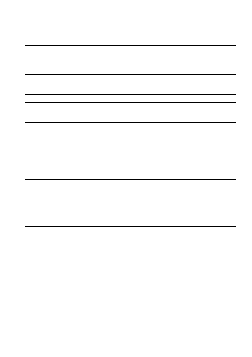
The technical specifications are at the beginning of this manual.
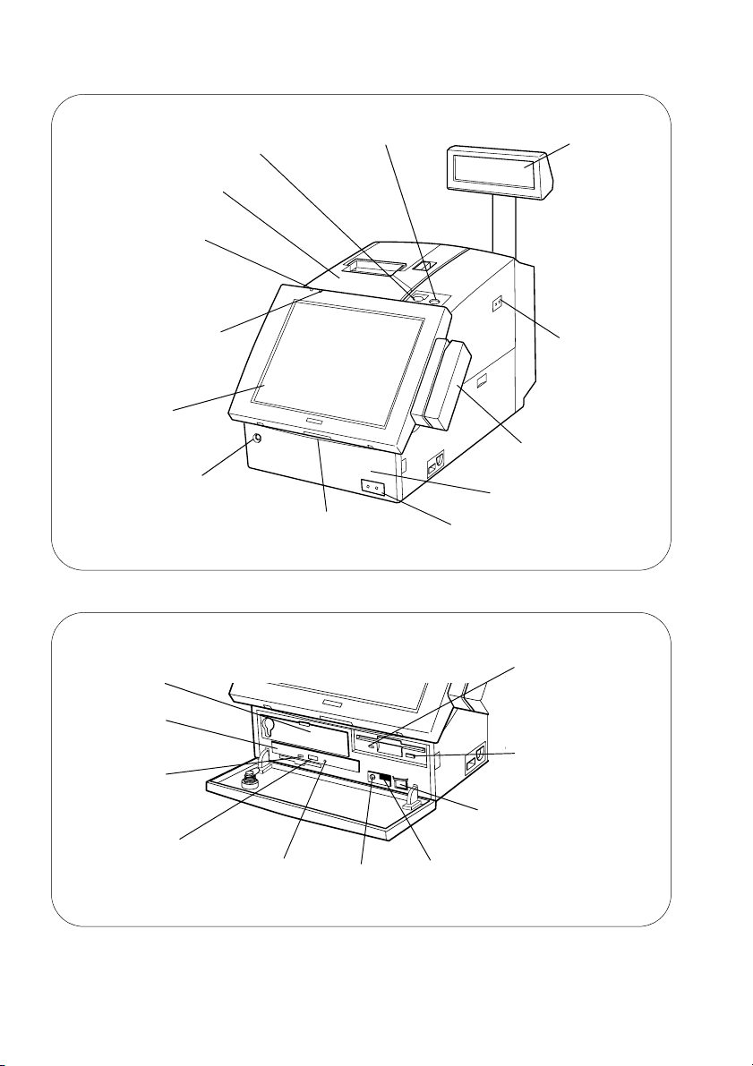
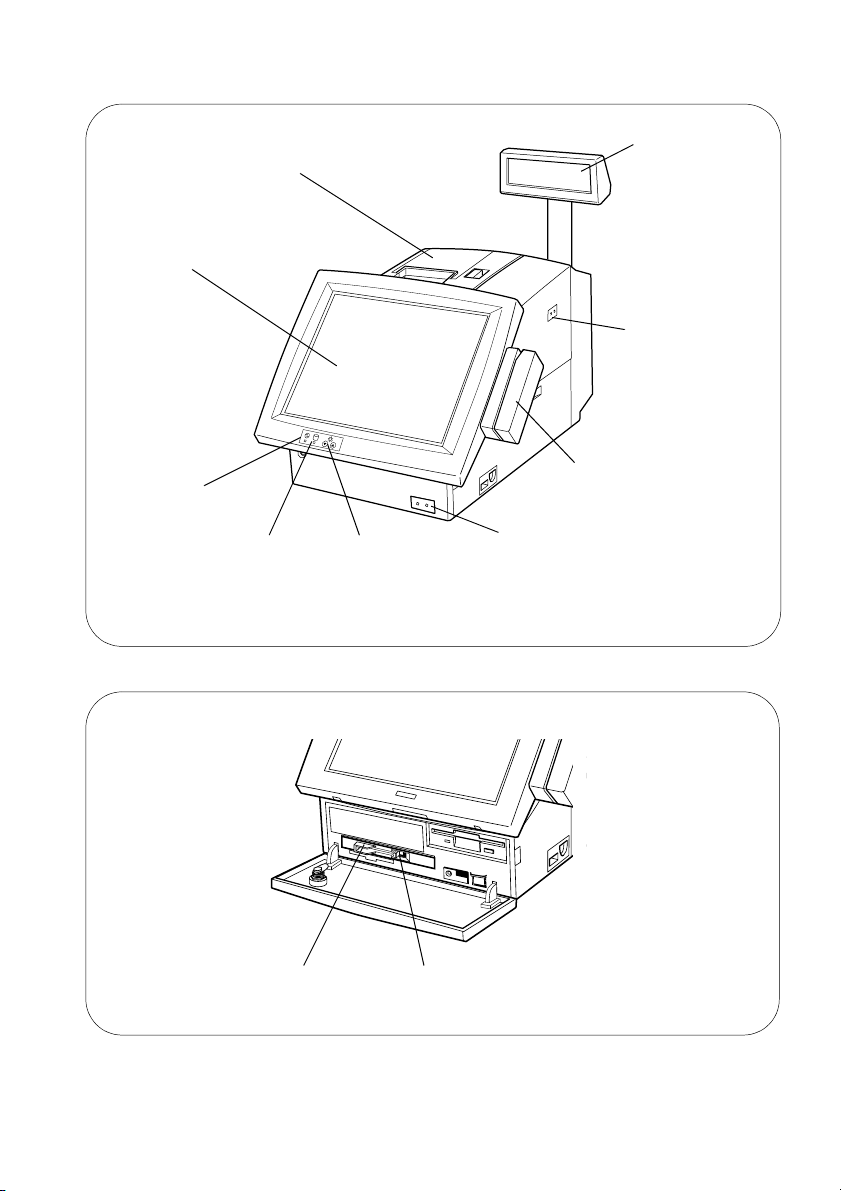
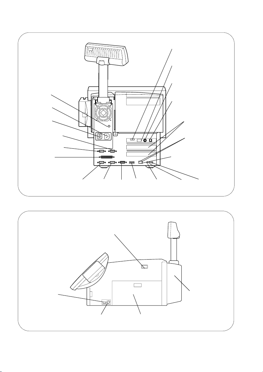
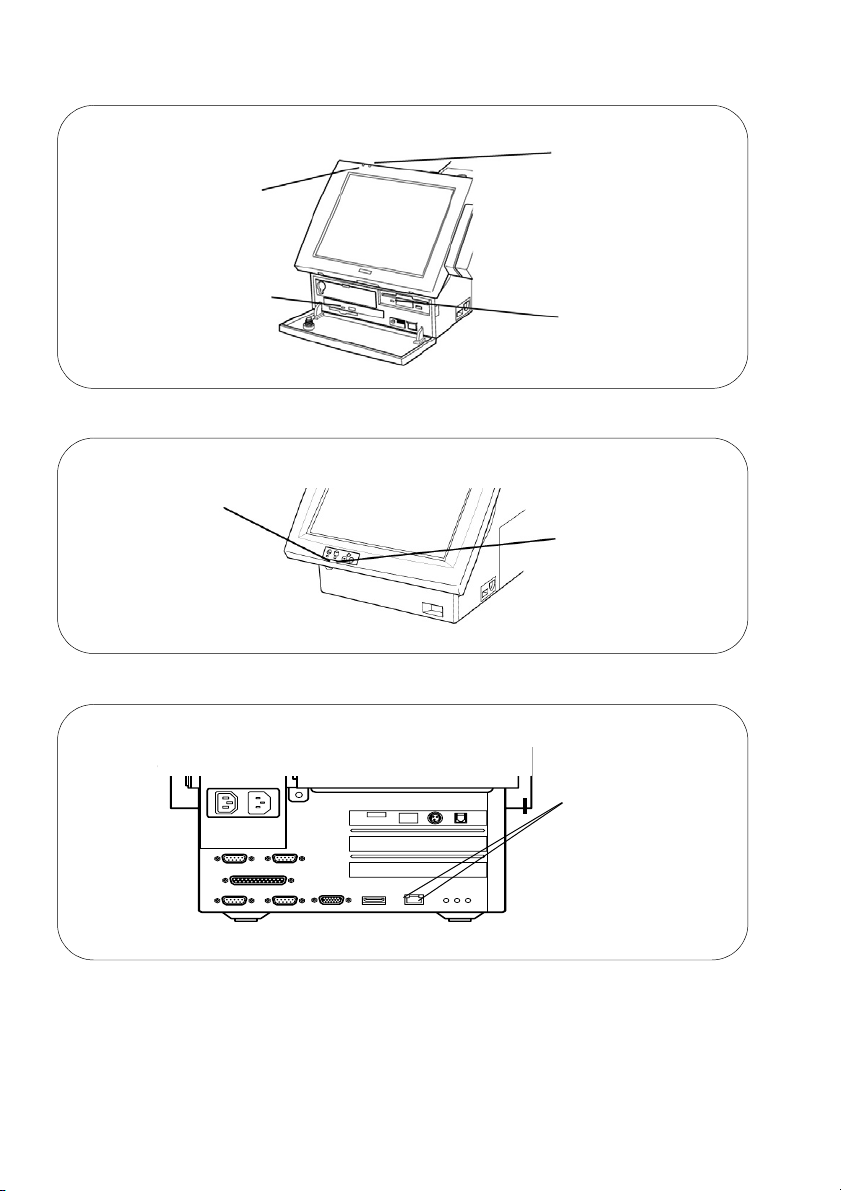
Illustrations
All of the illustrations are at the beginning of this manual. They are identified by letters (A, B, C . . .). In the
text the illustrations are referred to by these letters. (“See illustration A,” for example.) Some of these
illustrations have numbered arrows or lines pointing to parts of the illustration. See the list below for the
meaning of the numbers.
1. power LED 14. FDD LED 26. customer display jumper
2. printer unit (option) 15. FDD eject button 27. customer display connector
3. paper feed switch 16. speaker volume 28. TM power supply connector
4. key lock 17. reset switch 29. DK connector
5. customer display (option) 18. CD-ROM eject hole 30. PCI slots
6. main power switch 19. CD-ROM eject button 31. Ethernet connector
7. MSR unit (option) 20. CD-ROM LED 32. AC outlet
8. front cover 21. CD-ROM drive 33. AC inlet
9. soft power switch 22. HDD slot 34. fuse
Specifications
10. lock switch 23. LCD brightness adjustment
11. front cover key lock 36. side cover
12. LCD unit (option) 24. Front CompactFlash Adapter 37. keyboard/mouse connector
13. HDD LED 25. eject button
All rights reserved. No part of this document may be reproduced, stored in a retrieval system, or transmitted in any form or
by any means, electronic, mechanical, photocopying, recording, or otherwise, without the prior written permission of Seiko
Epson Corporation. No patent liability is assumed with respect to the use of the information contained herein. While every
precaution has been taken in the preparation of this document, Seiko Epson Corporation assumes no responsibility for errors
or omissions. Neither is any liability assumed for damages resulting from the use of the information contained herein.
Neither Seiko Epson Corporation nor its affiliates shall be liable to the purchaser of this product or third parties for
damages, losses, costs, or expenses incurred by purchaser or third parties as a result of: accident, misuse, or abuse of this
product or unauthorized modifications, repairs, or alterations to this product, or (excluding the U.S.) failure to strictly
comply with Seiko Epson Corporation’s operating and maintenance instructions.
Seiko Epson Corporation shall not be liable against any damages or problems arising from the use of any options or any
consumable products other than those designated as Original Epson Products or Epson Approved Products by Seiko
Epson Corporation.
®
EPSON
is a registered trademark of Seiko Epson Corporation.
®
Intel
, MMX™ Celeron™, and Pentium® are either trademarks or registered trademarks of Intel Corporation.
®
MS-DOS
, Microsoft®, Windows® and Windows NT® are registered trademarks of Microsoft Corporation in the United
States, other countries, or both.
buttons
35. rear cover
English
CompactFlash™ is a trademark of SanDisk Corporation.
®
IBM
, PC/AT®, and PS/2® are registered trademarks or trademarks of International Business Machines Corporation in
the United States, other countries, or both.
®
CHIPS
is registered trademark of Intel Corporation.
Sound Blaster
BaySwap
General Notice: Other product and company names used herein are for identification purposes only and may be
trademarks of their respective companies.
NOTICE: The contents of this manual are subject to change without notice. Please contact us for the latest information.
Copyright © 2003 by Seiko Epson Corporation, Nagano, Japan.
®
is a registered trademark of Creative Technology Ltd. In the United States, other countries, or both.
™
is a trademark of Phoenix Technologies Ltd.
EMC and Safety Standards Applied
Product Name: IM-320
Model Name: M156X
The following standards are applied only to the units that
are so labeled.
Europe: CE marking
North America: EMI: FCC/ICES-003 Class A
Japan: EMC: VCCI Class A
Oceania: EMC: AS/NZS 3548 Class A
Safety: UL 1950-3rd/ CSA C22.2
No. 950-95
WARNING
The connection of a non-shielded printer interface cable to
this device will invalidate the EMC standards of this device.
You are cautioned that changes or modifications not
expressly approved by SEIKO EPSON Corporation could
void your authority to operate the equipment.
The following standard applies to the IR320 equipped
with optional CD-ROM or CD-R/RW drive.
CLASS 1 LASER PRODUCT EN 60825
UL1950
AC Cord:
Detachable, maximum 4.5 m (14.76 ft) long.
Listed, CN, rated minimum 125 V, 7A, having a
Type SPT-2, SVT or SJT flexible cord.
One end terminates with a parallel blade, grounding,
molded-on, attachment plug with a 15 A, 125 V
(NEMA 5-15P) for 100-120 V input, 15 A, 250 V
(NEMA 6-15P) for 200-240 V input configuration;
other end terminates with molded-on appliance
coupler.
CE Marking
The unit conforms to the following Directives and Norms:
Directive 89/336/EEC EN 55022 Class A
Directive 73/23/EEC Safety: EN 60950
EN 55024
IEC 61000-4-2
IEC 61000-4-3
IEC 61000-4-4
IEC 61000-4-5
IEC 61000-4-6
IEC 61000-4-11
EN 61000-3-2
EN 61000-3-3
WARNING
This is a Class A product. In a domestic environment this
product may cause radio interference in which case the
user may be required to take adequate measures.
CAUTION:
Connecting an outdoor overhead LAN cable directly
to your product may lead to lightning damage. If you
need to connect such a cable to your product, the
cable must be protected against an electrical surge
between the cable and your product. You should
avoid connecting your product to a non-surge
protected outdoor overhead LAN cable.
FCC Compliance Statement For
American Users
This equipment has been tested and found to comply with
the limits for a Class A digital device, pursuant to Part 15
of the FCC Rules. These limits are designed to provide
reasonable protection against harmful interference when
the equipment is operated in a commercial environment.
This equipment generates, uses, and can radiate radio
frequency energy and, if not installed and used in
accordance with the instruction manual, may cause
harmful interference to radio communications. Operation
of this equipment in a residential area is likely to cause
harmful interference, in which case the user will be
required to correct the interference at his own expense.
2 IR-320 User’s Manual
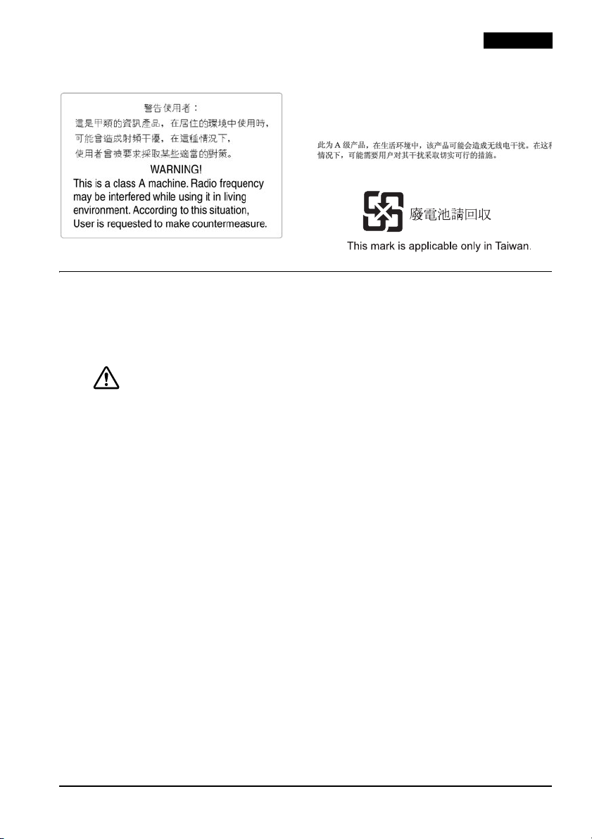
For Taiwanese Users For Canadian Users
This Class A digital apparatus complies with Canadian
ICES-003.
For Chinese Users
Recycle Mark for Taiwan
Safety Precautions
This section presents important information intended to ensure safe
and effective use of this product. Read this section carefully, and store
it in an accessible location.
WARNING:
Turn off the main power switch immediately and unplug the power cord
if the IR-320 produces smoke, a strange odor, or unusual noise. Continued
use may lead to fire or electric shock. Contact your dealer or an EPSON
service center for advice.
Never attempt to repair this product yourself. Improper repair work can
be dangerous.
Never disassemble or modify this product. Tampering with this product
may result in injury, fire, or electric shock.
Never insert or disconnect the power plug with wet hands. Doing so may
result in severe shock.
Do not allow foreign objects to fall into this product. Penetration by
foreign objects may lead to fire or shock.
If water or other liquid spills into this product, turn off the side power switch,
unplug the power cord immediately, and then contact your dealer or an
EPSON service center for advice. Continued usage may lead to fire or shock.
Always supply power directly from a standard domestic power outlet.
Do not place multiple loads on the power outlet (wall outlet).
Overloading the outlet may lead to fire.
The equipment must be installed near the electrical outlet, and the
outlet must be easily accessible.
Do not attempt to open or disassemble the internal lithium battery. This
could result in burns or release of hazardous chemicals.
English
IR-320 User’s Manual 3

English
Do not charge or leave the internal lithium battery in a hot place such as
near a fire or on a heater because it could overheat and ignite.
When you dispose of the internal lithium battery, insulate it by wrapping
the terminals with tape. Mixing the battery with other metals or batteries
may lead to fire, heat, or explosion.
Be sure your power cord meets the relevant safety standards and
includes a power system ground terminal (PE terminal).
Handle the power cord with care. Improper handling may lead to fire or
shock.
Do not modify or attempt to repair the cord.
Do not place any object on top of the cord.
Avoid excessive bending, twisting, and pulling of the cord.
Do not place the cord near heating equipment.
Check that the plug is clean before plugging it in.
Be sure to push the prongs all the way in.
Do not use a damaged cord.
Regularly remove the power plug from the outlet and clean the base of
the prongs and between the prongs. If you leave the power plug in the
outlet for a long time, dust may collect on the base of the prongs, causing
a short and fire.
CAUTION:
When replacing the battery, use only an equivalent type battery
recommended by the manufacturer. If your system has a module
containing a lithium battery, replace it only with the same module type
made by the same manufacturer. The battery contains lithium and can
explode if not properly used, handled, or disposed of.
Do not connect cables other than those specified in this manual. Doing
so may result in fire or improper operation.
Do not connect the unit to electrical outlets that are close to devices
that generate voltage fluctuations or electrical noise. In particular, stay
clear of devices that use large electric motors.
Always connect the power cable to the IR-320 before plugging it into the
wall outlet.
Be sure to push the plug of the power cord all the way into the AC inlet of
this product. The plug should make contact with the back of the inlet.
When disconnecting the power cable, hold the plug firmly. Do not tug
on the cord itself.
Be sure to set this product on a firm, stable, horizontal surface. The
product may break or cause injury if it falls.
4 IR-320 User’s Manual

English
Do not use the unit in locations subject to high humidity or dust levels.
Excessive humidity and dust may cause equipment damage, fire, or shock.
Do not use the product where inflammable fumes of gasoline, benzine,
thinner or other inflammable liquids may be in the air. Doing so may cause
an explosion or fire.
Do not place heavy objects on top of this product. Equipment may fall or
collapse, causing breakage and possible injury.
To ensure safety, unplug this product before leaving it unused for an
extended period.
Do not drop, bump, or otherwise subject this product to strong vibration
or impact.
Do not block the openings on this product. They are provided for the
ventilation necessary to ensure reliable operation and protection from
overheating.
Be sure to attach all covers after setup. If they are not attached, foreign
matter may enter this product and it may not operate correctly.
Never clean the product with thinner, benzene, alcohol, or other such
solvent.
Do not use this product with any voltage other than the specified one.
Doing so may lead to fire.
When a power cable for the TM printer is connected, do not short-circuit
its connector pins.
Do not insert fingers or foreign matter into the CD-ROM disk tray or
openings. Doing so may lead to fire, shock, or injury.
Do not insert fingers or foreign matter into the Front CompactFlash
TM
Adapter opening. Doing so may cause equipment damage.
Never hold this product by the rear cover, the front panel, or the
CD-ROM disk tray. They cannot support the weight of the product, so it
may fall onto the floor.
Make sure that the total power requirements of all devices receiving
power from this product do not exceed the power limitation. See the
specifications for more detailed information.
Be sure to use this product with all covers attached.
Be careful not to cut your finger on any edge of the unit.
Be sure to use EPSON supplied DIMMs, HDDs, CPUs, and KBs.
To get the latest information about which CompactFlash Memory Card
or Adapter or PCI board can be used with this product, contact your
EPSON dealer.
If you turn off the unit, wait longer than 10 seconds before you turn it on
again.
Be sure to attach the HDD cover when you use this product. If the cover
is not attached, the product may not operate correctly.
IR-320 User’s Manual 5

English
Notes on Using the Product for the First Time
If you use the product for the first time or have not used it for a long
time, please note the following:
Charging the Battery
Before using the product, if the optional battery unit OI-R03 is installed,
be sure to fully charge the battery unit.To fully charge the battery unit,
leave the IR-320 with the power turned on for approximately 32 hours.
Notes on Installing a Commercially Purchased
Windows 2000 or Windows XP
When installing a commercially purchased Windows 2000 or
Windows XP, nothing will be displayed in the middle of the setup.
Follow the procedures below to install commercially purchased
Windows.
Windows 2000
1. Connect the keyboard and mouse to the IR-320.
2. Start up from the Windows 2000 CD-ROM.
3. The setup wizard is started and the welcome message appears.
4. Press the Enter key to execute “To set up Windows 2000 now.”
5. The “License Agreement” appears. Confirm it and press the F8 key
to select “I agree.”
6. Follow the wizard to format the hard disk on which you are going
to install Windows 2000.
7. When you finish copying files to the hard disk, restart from the
hard disk.
8. When the “Regional Settings” dialog box appears, press the
SHIFT + F10 keys to start the command prompt.
9. Remove the Windows 2000 CD-ROM, and insert the driver
CD-ROM for the IR-320.
10. Execute the win2k_xpe67.exe file, which is in the
D:\WIN2K\VIDEO folder.
11. Install the video driver, following the wizards.
12. When the setup is complete, the dialog box that instructs you to
restart appears. Press “No, I will restart my computer later.” and
then press the Finish button.
13. Enter “Exit” at the command prompt to exit.
14. Remove the driver CD-ROM for the IR-320 and then insert the
Windows 2000 CD-ROM.
6 IR-320 User’s Manual

15. You will be taken back to the Windows 2000 setup screen. Follow
the onscreen instructions to enter the necessary information.
16. When the setup is complete, the dialog box that instructs you to
restart appears. Press the Finish button to restart.
17. The “Network Identification Wizard” starts. Press the Next button
to execute it.
18. Set a password and press the Next button.
19. Press the Finish button to exit the “Network Identification Wizard.”
20. Install the Chipset driver, network driver, touch panel driver, and
sound driver from the driver CD-ROM for the IR-320.
Windows XP
1. Connect the keyboard and mouse to the IR-320.
2. Start up from the Windows XP CD-ROM.
3. The setup wizard is started and the welcome message appears.
4. Press the Enter key to execute “To set up Windows XP now.”
5. The “License Agreement” appears. Confirm it and press the
F8 key to select “I agree.”
6. Follow the wizard to format the hard disk on which you are going
to install Windows XP.
7. When you finish copying files to the hard disk, restart from the
hard disk.
8. When the “Regional and Language Options” dialog box appears,
press the SHIFT + F10 keys to get the command prompt.
9. Remove the Windows XP CD-ROM and then insert the driver
CD-ROM for the IR-320.
10. Execute the win2k_xpe67.exe file, which is in the
D:\WINXP\VIDEO folder.
11. Install the video driver, following the wizards.
12. When the setup is complete, the dialog box that instructs you to
restart appears. Press “No, I will restart my computer later.” and
then press the Finish button.
13. Enter “Exit” at the command prompt to exit.
14. Remove the driver CD-ROM for the IR-320 and then insert the
Windows XP CD-ROM.
15. Follow the onscreen instructions to enter the necessary
information.
16. When the installation is finished, the system will restart.
17. Install the Chipset driver, network driver, and touch panel driver
from the driver CD-ROM for the IR-320.
English
IR-320 User’s Manual 7

English
Re-setting the BIOS
If the built-in battery is replaced, the settings of the real-time clock and
the CMOS will be lost. In this case, follow the procedures below to set
the BIOS again.
1. Connect an external keyboard to the keyboard/mouse connector
of the IR-320.
2. Turn on the IR-320.
3. While the following message is displayed, press the Del key.
Press DEL to enter SETUP.
4. The BIOS setup utility is started. You need to do the following
three actions for the BIOS setup utility:
• Load the setup default.
• Set the Date/Time.
• Set the battery unit (OI-R03).
5. Load the setup default (already adjusted in advance so that the
IR-320 can operate at its best).
• Select “Load Optimized Defaults” with the cursor key; then
press the Enter key.
• When “Load Optimized Defaults (Y/N)?” is displayed, press
the Y key; then the Enter key. The setup default is loaded.
• Press the Esc key to return to the main menu.
6. Set the Date/Time.
• Select “Standard CMOS Features” with the cursor key; then
press the Enter key.
• Select the item of “Date/Time” with the cursor and change the
setting with the PageUp key and PageDown key.
• When the setting is complete, press the Esc key to return to the
main menu.
7. Set up the battery unit. If it is not installed, you do not need to do
the following:
• Select “Power Management Setup” with the cursor; then press
the Enter key.
• Select “System Battery” with the cursor key.
• Change the setting to “Equipped” with the PageUp key.
• When the setting is complete, press the Esc key to return to the
main menu.
8 IR-320 User’s Manual

8. Select “Save & Exit Setup” with the cursor key; then press the
Enter key.
9. When “Save to CMOS and Exit (Y/N)?” is displayed, press the Y
key; then the Enter key. The utility setup is finished.
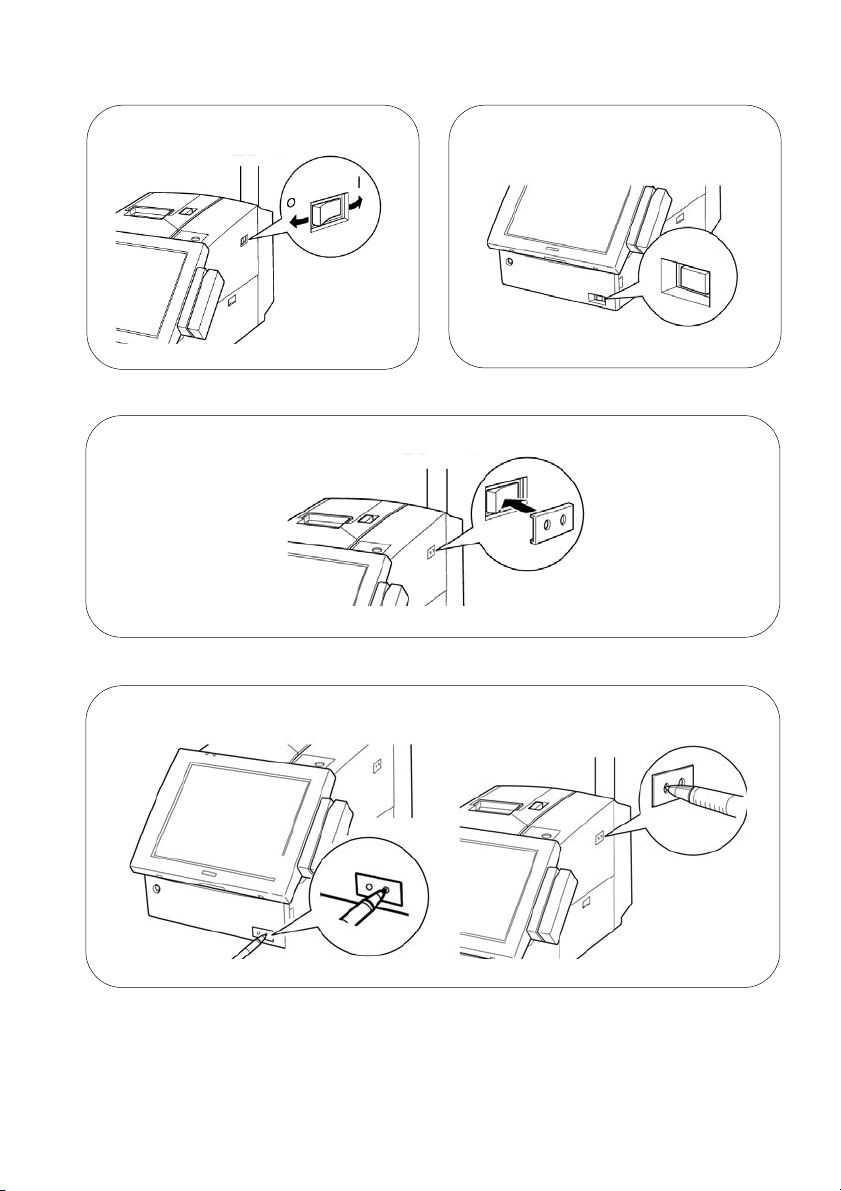
Power
When you use this product for the first time, turn on the main power
switch. The “O” mark indicates off, and the “|” mark indicates on, as
shown in illustration A.
The main power switch should usually be kept on. Turn off the unit’s
main power switch only when attaching peripherals, before
transporting it, when it will not be used for an extended period of time,
or in the unlikely event that the unit produces strange noises or smoke.
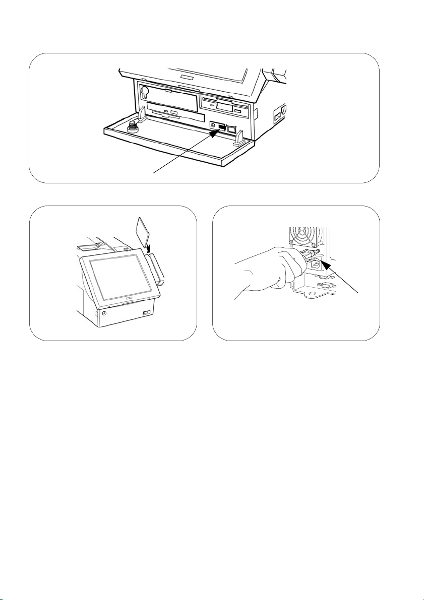
With the main power switch on, you can press the soft power switch
on the front of the unit to turn the unit on and off, as shown in
illustration B. The soft power switch uses software to turn your system
on and off, but even when the unit is turned off with this switch, a
small amount of current is flowing.
When a problem in the unit causes the protection circuit to be used, the
soft switch does not work. If this happens, turn off the main power
switch, remove the cause of the problem and wait for about 10 minutes.
Then turn on the main power switch and then the soft switch.
English
Power Off
You usually turn off power through your software. The power off
procedure varies depending on the operating system and BIOS used.
Power Switch Covers
This product includes 2 switch covers that prevent the unit from being
turned on or off accidentally. To install a switch cover, place the switch
cover over the switch, and press it into place, as shown in illustration C.
When you have installed a switch cover, operate the switch by
pushing a thin object, such as a pencil, through the holes in the switch
cover, as shown in illustration D.
IR-320 User’s Manual 9
English
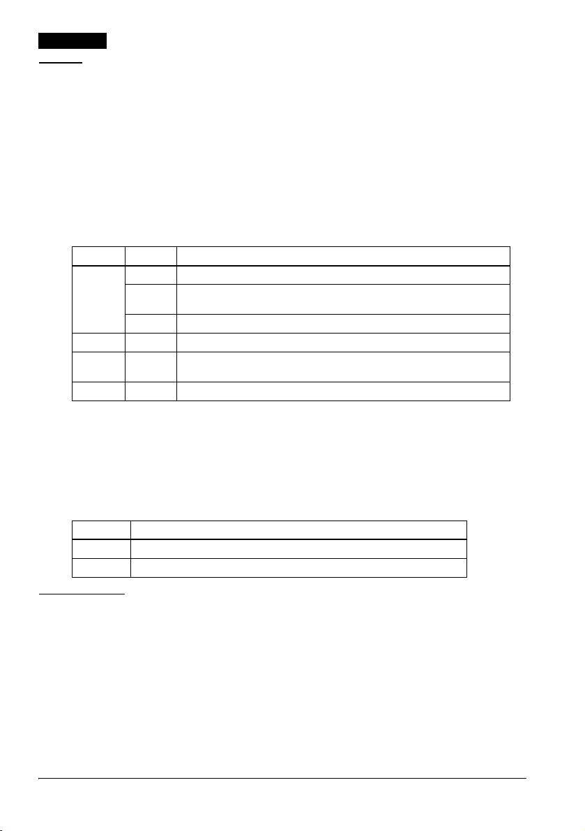
LEDs
The LCD and the keyboard units have 2 LEDs each, and the FDD and
CD-ROM have 1 each. The place and number of LEDs differ
depending on the options installed. Two examples are shown.
The unit with the 84 Keyboard unit and the DM-LR104 series LCD
unit installed is shown in illustration E.
The unit with the DM-LR121 series LCD unit installed is shown in
illustration F.
These LEDs have the following meaning:
LED Color Meaning
Power
LED
HDD Green HDD is being accessed.
CD-ROM Orange CD-ROM/R/RW is being accessed. (No LED if CD-ROM drive is not
FDD Green FDD is being accessed.
Rear Side LEDs
Green Power is turned on (during normal operation).
Flashing
green
Off Power is off.
Backup is in progress using the power from the optional battery unit
(OI-R03).
installed.)
There are 2 LEDs on the rear side (shown in illustration G) showing
the access state to the network using the LAN. They are on only when
the LAN is being accessed.
These LEDs have the following meaning:
LED Meaning
Green Lights Connected with 100BASE-TX.
Orange Lights accessing (Transmitting and receiving) the network
Front Key
The front key (shown in illustration H) is for the cover lock on the front
panel.
With the front panel locked, the floppy disk, CompactFlash card, and
CD-ROM/R/RW can be removed only by a person with a front key.
Insert the front key into the cover lock hole, and turn it while slightly
pushing in to lock or unlock the front panel.
10 IR-320 User’s Manual
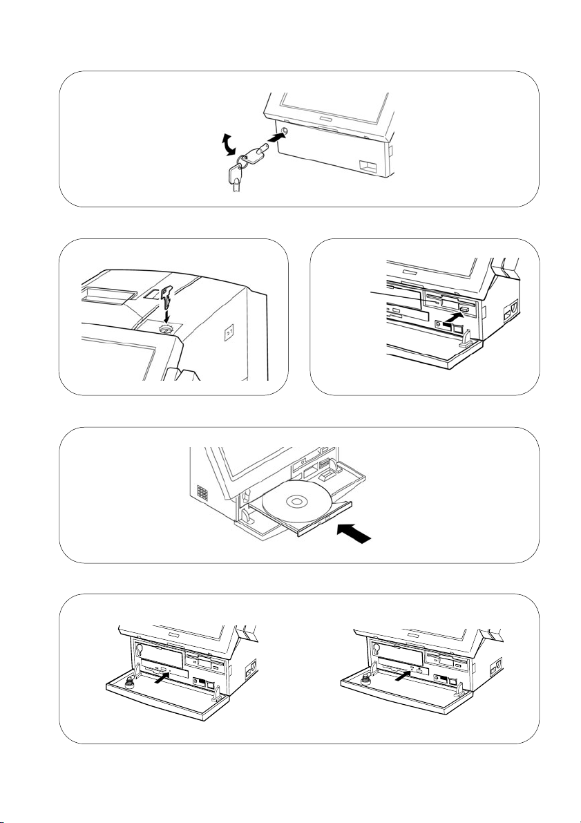
Key Lock Keys
A set of 5 Key Lock keys is provided. Each key allows the user to access
the function level you define for that key position. The Key Lock keys
are used by inserting them into the lock on top of the IR-320, as shown
in illustration I.
The Key Lock keys place restrictions on the functions that can be used by
the operator. The Key Lock key can be turned to 6 positions (from 1 to 6).
Each key can be given a different access range to prevent use of higher
functions by unauthorized users.
Inserting and Removing a Floppy Disk
Insert the floppy disk with the label side up in the floppy disk drive.
When the floppy disk is inserted correctly, the eject button pops out.
To remove a floppy disk, make sure the access LED of the floppy disk
drive is off. Then press the eject button, as shown in illustration J.
Take out the floppy disk carefully.
Inserting and Removing a CD-ROM/R/RW
1. Press the eject button of the CD-ROM, CD-R/RW drive; the tray
comes out.
2. Put the CD-ROM/R/RW with the label side up in the tray.
English
CAUTION:
Push the CD-ROM/R/RW down slightly to ensure that it is firmly set in
the tray. Otherwise the CD-ROM/R/RW may be damaged.
3. Gently push the tray into the CD-ROM, CD-R/RW drive, as
shown in illustration K.
To remove a CD-ROM/R/RW, follow these steps.
1. Check that the CD-ROM LED is off.
2. Press the eject button; the tray comes out slightly.
3. Pull the tray out fully, and remove the CD-ROM/R/RW carefully.
IR-320 User’s Manual 11
English
CD-ROM/R/RW Emergency Ejection
When the CD-ROM, CD-R/RW drive does not function properly, you
can remove the CD-ROM/R/RW by following the steps below:
1. Turn off the IR-320.
2. Insert a small thin object, such as an extended paper clip, in the
CD-ROM eject hole. (Shown in illustration L, with the CD-ROM drive
shown on the left and the CD-R/RW drive shown on the right.)
3. The disk tray pops out slightly; then pull it out gently.
CompactFlash Cards
Handling CompactFlash Cards
CompactFlash cards are composed of precision electronic components.
Follow the cautions below to prevent incorrect operation or failure of
the cards.
CAUTION:
Do not touch the terminals of a CompactFlash card with your fingers or
any metal object because electrostatic discharge may damage internal
components. Before touching a card, discharge your electrostatic charge
by touching a metal fixture. Failure to do so may damage the system.
Unless you are using BaySwap
CompactFlash card while the system is on. If you have installed BaySwap,
refer to the BaySwap operation procedure below. Failure to observe these
precautions may result in system damage.
Do not bend or drop the card, and protect it from impact.
Protect the card from excessive heat, moisture, and direct sunlight
during use and storage.
®
under Windows NT, never remove the
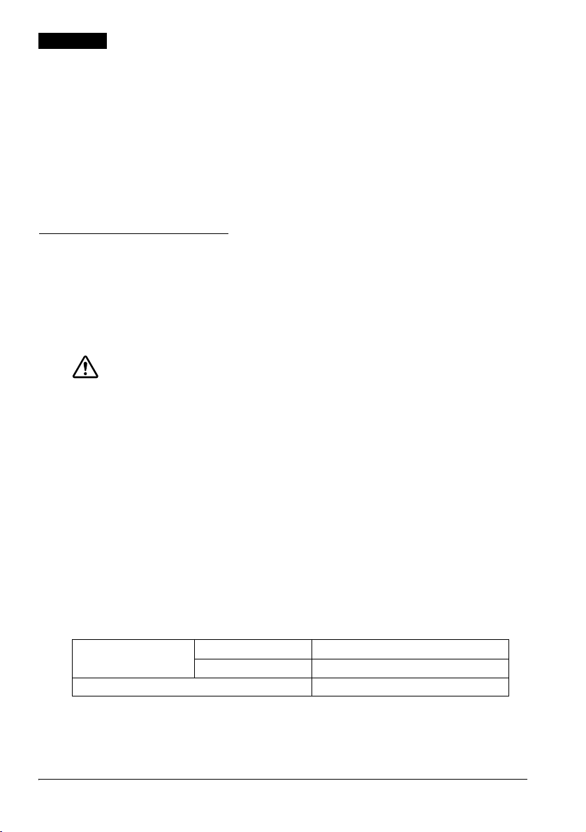
Inserting and Removing CompactFlash Cards
Observe the following requirements when inserting and removing
CompactFlash cards.
When the power is on BaySwap not in use: Inserting and removing not possible.
BaySwap in use: Inserting and removing possible.
When the power is off Inserting and removing possible.
See “Using BaySwap” for details on the procedure for inserting and
removing CompactFlash cards when BaySwap is in use.
BaySwap can be used only with Windows NT.
12 IR-320 User’s Manual
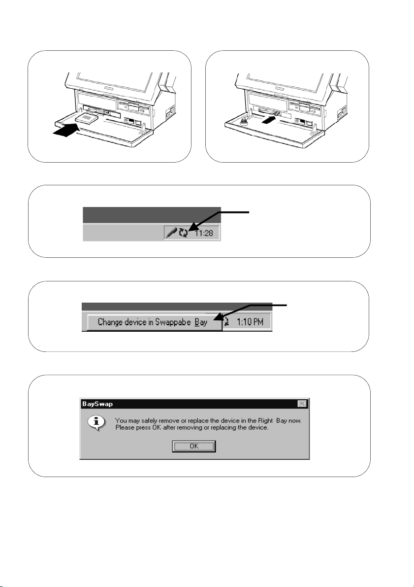
Inserting a CompactFlash Card
Insert the CompactFlash card face up firmly into the slot to set it in
place, as shown in illustration M.
Removing a CompactFlash Card
Press the eject button firmly. The CompactFlash card is ejected slightly
from the slot so you can remove it, as shown in illustration N.
Using BaySwap
If you are running Windows NT with the BaySwap program installed,
read these instructions.
The BaySwap icon resides in the task bar, as shown in illustration O,
when Windows NT is booted.
Operation Procedure
Make sure that reading or writing is not being performed on the
CompactFlash card before removing it.
1. Click the icon in the task bar, and then click [Change device in
Swappable Bay]. (See illustration P.)
2. The dialog box shown in illustration Q is displayed. Insert or
remove the card at this point.
3. Click OK once the card has been inserted or removed.
English
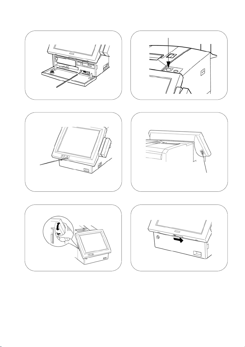
Reset
Reset restarts the computer while the power is on. Reset is necessary
only when software has entered an endless loop.
CAUTION:
Do not press the reset switch unless the system fails to respond.
When the system is reset, all data in memory is lost.
Perform a reset by following the procedure below.
1. Open the front panel. If the front panel is locked, unlock it using
the front key.
2. Push the reset switch with a pointed object such as a pen, as
shown in illustration R.
IR-320 User’s Manual 13

English
Paper Feed with a Printer
If a printer is connected to the IR-320, press the paper feed button to
feed paper, as shown in illustration S.
LCD Brightness Adjustment
You can adjust LCD brightness by using the controls marked A and B
in illustrations T and U.
LCD/Keyboard Angle Adjustment
The angle of the LCD/keyboard unit is adjustable, but the adjusting
positions differ depending on the LCD unit. Follow these steps to
change the angle.
DM-LR121series LCD unit
1. Adjust the angle of the LCD unit while pressing the lock lever on
the left side of the LCD unit, as shown in illustration V.
2. When you release the lock lever, the angle is fixed.
3. Move the LCD unit slightly up and down to firmly fix it.
DM-LR104 series LCD unit and DM-KR084 Keyboard
1. Slide the LCD/keyboard unit lock switch to the unlock position,
as shown in illustration W.
2. Adjust the angle to the position you want.
3. Set the lock switch to the lock position again.
Speaker Volume Adjustment
Adjust speaker volume by following the procedure below.
1. Open the front panel. If the front panel is locked, unlock the front
panel using the front key.
2. Turn the volume control to the left to turn down the volume. Turn
it to the right to turn up the volume. (See illustration X.)
How to Read a Magnetic Stripe Card
When you attach an MSR (Magnetic Stripe Reader) unit, magnetic
stripe cards can be read.
Hold the card as shown in illustration Y, and pass it through the MSR
unit.
14 IR-320 User’s Manual

Changing the AC Outlet Circuit Fuse
An overcurrent from the AC outlet can blow the fuse. Follow the steps
below to replace it.
1. Turn off the equipment connected to the AC outlet and unplug the
power cable from the AC outlet.
2. Turn off the IR-320 and unplug the power cable from the AC inlet.
3. Using a flathead screwdriver, push and twist the fuse holder to
remove it, as shown in illustration Z.
4. Replace the old fuse with an new one and replace the fuse holder.
English
IR-320 User’s Manual 15

English
16 IR-320 User’s Manual

IR-320
Bedienungsanleitung
Deutsch
Die technische Daten befinden sich am Anfang dieses Handbuchs.
Abbildungen
Alle Abbildungen befinden sich am Anfang dieses Handbuchs und sind mit den Buchstaben (A, B, C …)
gekennzeichnet. Im Text wird auf die Abbildungen anhand dieser Buchstaben Bezug genommen (z.B.
“Siehe Abbildung A”). Einige dieser Abbildungen haben numerierte Pfeile bzw. Linien, die auf einen Teil
der Abbildung zeigen. Die Bedeutung der Nummern ist unten aufgeführt.
Technische Angaben
1. Betriebsanzeige 14. Diskettenlaufwerk
2. Druckereinheit (Option)
3. Papiervorschubschalter 15. Diskettenauswurfknopf 27. Kundenanzeigenanschluss
4. Schlüsselschalter 16. Lautstärkeregler 28. TM-Spannungsversorgungs-
5. Kunden-Anzeige (Option) 17. Reset-(Rücksetz-)Schalter
6. Netzschalter 18. CD-ROM-Notauswurfloch 29. Kassenschubladenanschluss
7. Magnetkartenlese (Option; MSR) 19. CD-ROM-Auswurftaste 30. PCI-Steckplätze
8. Frontabdeckung 20. CD-ROM-Zugriffsanzeige
9. Ein-/Aus-Schalter 32. Wechselspannungsausgang
10. lLCD-Verriegelung 21. CD-ROM-Laufwerk 33. Wechselspannungseingang
11. Frontabdeckungsschloss 22. Festplattenabdeckkung 34. Sicherung
12. LCD-Einheit (Option) 23. LCD-Helligkeitseinstellknöpfe 35. Rückseitenabdeckung
13. Festplattenzugriffsanzeige
(HDD-LED)
Alle Rechte vorbehalten. Diese Veröffentlichung darf ohne ausdrückliche schriftliche Genehmigung der Seiko Epson
Corporation nicht reproduziert, in einem Abrufsystem gespeichert oder in beliebiger Form und auf jedwede Weise
übermittelt werden, weder durch fotokopieren, aufzeichnen, noch auf elektronische, mechanische oder sonstige Weise.
Für die hierin enthaltenen Informationen wird keine Patenthaftung übernommen. Obgleich bei der Zusammenstellung
dieser Anleitung mit Sorgfalt vorgegangen wurde, übernimmt die Seiko Epson Corporation keine Verantwortung für
Fehler und Auslassungen. Zudem wird keine Haftung übernommen für Schäden, die aus der Verwendung der hierin
enthaltenen Informationen entstehen.
Weder die Seiko Epson Corporation noch ihre Tochtergesellschaften sind dem Käufer dieses Produkts oder Drittparteien
gegenüber für Schäden, Verluste, Kosten oder Ausgaben haftbar, die für den Käufer oder etwaige Drittparteien aufgrund
von Unfall, Missbrauch oder Zweckentfremdung dieses Produkts, nicht autorisierten Modifikationen, Reparaturen oder
Produktumbauten sowie (mit Ausnahme USA) aufgrund des Versäumnisses anfallen. Die Bedienungs- und
Wartungsanleitungen der Seiko Epson Corporation sind genau einzuhalten.
zugriffsanzeige (FDD-LED)
(LED)
24. CompactFlash-Adapter, vorn 36. Seitenwand
25. CompactFlash-Auswurfknopf 37. Tastatur-/Mausanschluss
26. Kundenanzeigenschalter
(Handshake)
anschluss (24 V)
31. Ethernet-Anschluss

Deutsch
Die Seiko Epson Corporation ist nicht haftbar für Schäden oder Probleme, die bei Verwendung von Optionen oder
Verschleißteilen auftreten, die nicht als Original-Epson-Produkte oder von der Seiko Epson Corporation zugelassener
Epson Produkte gelten.
®
ist ein eingetragenes Warenzeichen der Seiko Epson Corporation.
EPSON
®
Intel
, MMX™ Celeron™ und Pentium® sind entweder Warenzeichen oder eingetragene Warenzeichen der Intel
Corporation.
®
MS-DOS
, Microsoft®, Windows® und Windows NT® sind in den USA und/oder anderen Ländern eingetragene
Warenzeichen der Microsoft Corporation.
CompactFlash™ ist ein Warenzeichen der SanDisk Corporation.
®
IBM
, PC/AT® und PS/2® sind Warenzeichen oder in den USA und/oder anderen Ländern eingetragene Warenzeichen
der Business Machines Corporation.
®
CHIPS
ist ein eingetragenes Warenzeichen der Intel Corporation.
Sound Blaster
BaySwap
Allgemeiner Hinweis: Weitere hierin verwendete Produkte und Firmennamen dienen nur zu Identifikationszwecken und
sind unter Umständen Warenzeichen der jeweiligen Firmen.
HINWEIS: Änderungen dieser Betriebsanleitung ohne Vorankündigung vorbehalten. Für die aktuellsten Informationen
setzen Sie sich bitte mit uns in Verbindung.
Copyright © 2003 Seiko Epson Corporation, Nagano, Japan.
®
ist ein in den USA und/oder anderen Ländern eingetragenes Warenzeichen von Creative Technology Ltd.
™
ist ein Warenzeichen von Phoenix Technologies Ltd.
Geltende EMC und Sicherheitsnormen
Produktname: IM-320
Modellname: M156X
Die folgenden Normen gelten nur für entsprechend
gekennzeichnete Geräte.
Europa: CE-Zeichen
Nordamerika: EMI: FCC/ICES-003 Klasse A
Japan: EMC: VCCI Klasse A
Ozeanien: EMC: AS/NZS 3548 Klasse A
Sicherheit: UL 1950/CSA C22.2
No. 950-95
WARNUNG
Beim Anschluss eines nicht abgeschirmten
Druckerschnittstellenkabels an dieses Gerät, entspricht
das Gerät nicht länger den EMC-Normen.
Sie werden darauf hingewiesen, dass Sie nach
Änderungen oder Modifikationen, die nicht ausdrücklich
von der SEIKO EPSON Corporation zugelassen wurden,
unter Umständen nicht länger zur Bedienung des Geräts
berechtigt sind.
Der folgende Standard betrifft den IR320, der optional mit
CD-ROM oder CD-R/RW Laufwerk ausgestattet ist.
KLASSE 1 LASER PRODUKT EN 60825
UL1950
Netzkabel:
Abnehmbar, maximal 4,5 m lang.
CN-geprüft, Nennaufnahme mindestens 125 V, 7 A,
mit flexiblem Kabel des Typs SPT-2, SVT oder SJT.
Das eine Ende weist einen Formstecker auf mit Parallel-
Anschlussstiften und Erdung, 15 A, 125 V
(NEMA 5-15P) für 100 - 120-V-Versorgung bzw. 15 A,
250 V (NEMA 6-15P) für 200 - 240 VEingangskonfiguration; am anderen Ende ist ein
Geräteformstecker befestigt.
18 IR-320 Bedienungsanleitung
CE-Zeichen
Der Drucker entspricht den folgenden Vorschriften und
Normen:
Direktive 89/336/EEC EN 55022 Klasse A
Direktive 73/23/EEC Sicherheit: EN 60950
EN 55024
IEC 61000-4-2
IEC 61000-4-3
IEC 61000-4-4
IEC 61000-4-5
IEC 61000-4-6
IEC 61000-4-11
EN 61000-3-2
EN 61000-3-3
WARNUNG
Dies ist ein Produkt der Klasse A. Bei Heimgebrauch
verursacht dieses Produkt unter Umständen
Radiointerferenzen, die vom Benutzer durch
entsprechende Maßnahmen zu beheben sind.
VORSICHT:
Beim Direktanschluss eines im Freien angebrachten LANKabels an das Produkt besteht Beschädigungsgefahr
durch Blitzschlag. Wenn ein Kabel dieser Art an Ihr Produkt
angeschlossen werden muss, ist es erforderlich, zwischen
dem Kabel und dem Produkt eine Überspannungsschutzvorrichtung anzubringen. Schließen Sie das Produkt
möglichst nicht an im Freien angebrachte LAN-Kabel
ohne Überspannungsschutz an.
GERÄUSCHPEGEL
Gemäß der Dritten Verordnung zum Gerätesicherheitsgesetz
(Maschinenlärminformations- Verordnung-3. GSGV) ist der
arbeitsplatzbezogene Geräusch-Emissionswert kleiner als
70 dB(A) (basierend auf ISO 7779).

Sicherheitsmaßnahmen
In diesem Abschnitt finden Sie wichtige Informationen zum sicheren und
effektiven Gebrauch dieses Produkts. Bitte lesen Sie diesen Abschnitt
sorgfältig durch und heben Sie ihn an einem leicht zugänglichen Ort auf.
WARNUNG:
Schalten Sie den IR-320 sofort aus und ziehen Sie den Netzstecker, wenn
Sie beim IR-320 Rauch bzw. ungewöhnliche Gerüche oder Geräusche
bemerken. Wenn der IR-320 weiter verwendet wird, besteht Brand- und
Stromschlaggefahr. Benachrichtigen Sie Ihren Händler oder ein EPSON
Service Center.
Versuchen Sie niemals, dieses Produkt eigenständig zu reparieren.
Unsachgemäße Reparaturarbeiten können gefährlich sein.
Zerlegen oder modifizieren Sie dieses Produkt nicht. Unsachgemäße
Arbeiten an diesem Produkt können zu Verletzungen, Brand oder
elektrischen Schlägen führen.
Stecken Sie das Netzkabel niemals mit nassen Händen ein oder ziehen es
heraus. Dies kann zu einem schweren elektrischen Schlag führen.
Vermeiden Sie das Eindringen von Fremdkörpern in dieses Produkt. Beim
Eindringen von Fremdkörpern besteht Brand- und Stromschlaggefahr.
Wenn Wasser oder sonstige Flüssigkeiten in dieses Produkt eindringen,
ziehen Sie sofort das Netzkabel heraus und benachrichtigen Sie einen
Fachhändler oder Ihr SEIKO EPSON Service Center. Wenn der IR-320 weiter
verwendet wird, kann dies einen Brand oder elektrische Schläge
verursachen.
Schließen Sie den IR-320 direkt an eine normale Haushaltssteckdose an.
Verwenden Sie keine Tischsteckdosen an der Wandsteckdose. Eine
Überlastung der Steckdose kann einen Brand verursachen.
Schließen Sie den IR-320 immer direkt an eine leicht zugängliche
Schukosteckdose an.
Versuchen Sie nicht, den internen Lithium-Akku zu öffnen oder
auseinanderzunehmen. Andernfalls besteht Gefahr von Verbrennungen
und der Freigabe von gefährlichen Chemikalien.
Halten Sie den internen Lithium-Akku von Hitze fern, wie z.B. von Kaminfeuer
und Heizgeräten, damit der Akku nicht überhitzt und kein Feuer fängt.
Überkleben Sie die Pole des Lithium-Akkus vor dem Entsorgen mit
Klebeband. Durch Kontakt des Akkus mit anderen Metallen oder Batterien
besteht, Brand-, Hitzeentwicklungs- und Explosionsgefahr.
Stellen Sie sicher, dass das Netzkabel den zutreffenden Sicherheitsnormen
entspricht und einen Erdungsleiter (Schutzkontakt) aufweist.
Deutsch
IR-320 Bedienungsanleitung 19

Deutsch
Seien Sie vorsichtig bei der Handhabung des Netzkabels. Die unsachgemäße
Verwendung kann zu einem Brand oder einem elektrischen Schlag führen.
Ändern oder reparieren Sie das Netzkabel nicht.
Stellen Sie keine Gegenstände auf das Kabel.
Vermeiden Sie übermäßige Biegungen, Drehungen oder Zugkräfte
am Kabel.
Verlegen Sie das Kabel nicht in der Nähe von Heizgeräten.
Sorgen Sie vor dem Einstecken des Steckers dafür, dass er sauber ist.
Stecken Sie den Stecker bis zum Anschlag in die Steckdose.
Verwenden Sie keine beschädigten Kabel.
Ziehen Sie den Netzstecker regelmäßig aus der Steckdose und reinigen
Sie den Sockel der Anschlussstifte und den Bereich zwischen den
Anschlussstiften. Wenn der Netzstecker lange Zeit in der Steckdose
verbleibt, kann sich am Sockel der Anschlussstifte Staub ansammeln und es
besteht Kurzschluss- und Brandgefahr.
VORSICHT:
Schließen Sie Kabel nur auf die in diesem Handbuch beschriebene Weise
an. Andere Kabelverbindungen können den IR-320 beschädigen und
einen Brand verursachen.
Schließen Sie den IR-320 nicht an Steckdosen an, die sich in der Nähe
von Geräten befinden, die Spannungsschwankungen und elektrische
Interferenzen erzeugen, insbesondere Geräte mit großen Elektromotoren.
Schließen Sie das Netzkabel STETS ZUERST am IR-320 an, ehe Sie es an
eine Wandsteckdose anschließen.
Stecken Sie das Ende des Netzkabels unbedingt bis zum Anschlag in den
Wechselspannungseingang dieses Produkts. Der Stecker muss Kontakt mit
dem hinteren Teil des Eingangs haben.
Ziehen Sie das Netzkabel nur am Stecker aus der Steckdose. Nicht am
Kabel selbst ziehen.
Stellen Sie dieses Produkt unbedingt auf einer festen, stabilen,
horizontalen Fläche auf. Das Produkt kann beim Fallen beschädigt werden
oder Verletzungen verursachen.
Verwenden Sie den IR-320 nicht an Orten mit hohem Feuchtigkeits- oder
Staubgehalt. Eine übermäßige Feuchtigkeits- oder Staubentwicklung kann
den IR-320 beschädigen oder einen Brand bzw. einen elektrischen Schlag
verursachen.
Verwenden Sie das Produkt nicht, wenn Gefahr besteht, dass die
Umgebungsluft mit brennbaren Dünsten von Benzin, Benzol,
Verdünnungsmitteln oder sonstigen brennbaren Flüssigkeiten angereichert
ist. Andernfalls besteht Explosions- und Brandgefahr.
Stellen Sie keine schweren Gegenstände auf dieses Produkt. Der IR-320
kann fallen oder beschädigt werden und dabei Gegenstände
beschädigen oder Personen verletzen.
20 IR-320 Bedienungsanleitung

Deutsch
Aus Sicherheitsgründen ziehen Sie bitte den Netzstecker aus der
Netzsteckdose, wenn Sie beabsichtigen, den IR-320 über einen längeren
Zeitraum nicht zu verwenden.
Lassen Sie den IR-320 nicht fallen, stoßen Sie nicht dagegen und setzen
Sie den IR-320 keinen sonstigen starken Erschütterungen und
Stoßeinwirkungen aus.
Achten Sie darauf, dass die Öffnungen des Produkts nicht blockiert
werden. Diese Öffnungen ermöglichen die für den zuverlässigen Betrieb
erforderliche Luftzirkulation und schützen vor Überhitzung.
Versäumen Sie nicht, nach dem Aufstellen sämtliche Abdeckungen
anzubringen. Andernfalls können Fremdkörper in das Produkt eindringen
und Störungen verursachen.
Reinigen Sie das Produkt keinesfalls mit Verdünnungsmittel, Benzol,
Alkohol oder ähnlichen Lösungsmitteln.
Betreiben Sie das Produkt nur mit der angegebenen Netzspannung.
Andernfalls besteht Feuergefahr.
Schließen Sie die Anschlusspole nach dem Anschließen von Stromkabeln
an TM-Druckern nicht kurz.
Keine Finger oder Fremdkörper in die CD-ROM Auflage oder Öffnungen
stecken. Andernfalls besteht Brand-, Stromschlag- und Verletzungsgefahr.
Keine Finger oder Fremdkörper in die Öffnung des CompactFlash
Frontadapters stecken. Andernfalls sind Produktbeschädigungen nicht
auszuschließen.
Halten Sie das Produkt niemals an der Rückwandabdeckung, der
Frontkonsole oder an der CD-ROM-Schublade fest. Da diese Komponenten
das Gewicht des Produkts nicht aushalten, kann das Produkt zu Boden
fallen.
Achten Sie darauf, dass die Gesamtstromaufnahme aller, von diesem
Produkt mit Strom versorgten Geräte die Anschlussgrenzwerte nicht
überschreiten. Weitere Einzelheiten hierzu, siehe Technische Daten.
Verwenden Sie den IR-320 nur, wenn die Abdeckungen an der Rückseite
und an den Seiten des IR-320 angebracht sind.
Bitte beachten Sie, dass die Kanten der Einheit scharf sind und bei
Unachtsamkeit Schnittverletzungen verursachen können.
Verwenden Sie nur von EPSON gelieferte DIMMs (Arbeitsspeicher),
HDDs (Festplatten), CPUs und KBs (Tastaturen).
Setzen Sie sich mit Ihrem EPSON Händler in Verbindung, wenn Sie die
aktuellsten Informationen zur richtigen Verwendung von CompactFlashSpeicherkarten, Adaptern oder PCI-Platinen wünschen, die für dieses
Produkt verwendet werden können.
Wenn Sie den IR-320 ausschalten, warten Sie 10 Sekunden, ehe Sie es
wieder einschalten.
Vergessen Sie vor Verwendung dieses Produkts nicht, die HDD-Abdeckung
anzubringen. Wenn die Abdeckung nicht angebracht ist, funktioniert das
Produkt unter Umständen nicht richtig.
IR-320 Bedienungsanleitung 21

Deutsch
Hinweise für den erstmaligen Produktgebrauch
Wenn Sie das Produkt erstmalig verwenden oder es längere Zeit nicht
benutzt haben, achten Sie bitte auf Folgendes:
Laden der Batterie
Falls die optionale Batterieeinheit OI-R03 installiert ist, achten Sie vor
Gebrauch des Produkts darauf, dass die Batterieeinheit vollständig
aufgeladen ist. Zum Aufladen der Batterie lassen Sie den IR-320 ca.
32 Stunden lang eingeschaltet.
Hinweise für die Installation eines im Handel erworbenen
Windows 2000 oder Windows XP
Beim Installieren eines kommerziell erworbenen Windows 2000 oder
Windows XP erscheint in der Mitte des Setups keine Anzeige. Installieren
Sie ein im Handel erworbenes Windows wie unten erläutert.
Windows 2000
1. Schließen Sie die Tastatur und die Maus an den IR-320 an.
2. Starten Sie den Computer mit der Windows 2000 CD-ROM.
3. Der Installationsassistent wird gestartet, und es erscheint die
Begrüßungsanzeige.
4. Drücken Sie die Eingabetaste, um “To set up Windows 2000 now”
auszuführen.
5. Nun erscheint das “License Agreement”. Bestätigen Sie dieses und
drücken Sie die Taste F8, um “I agree” zu wählen.
6. Befolgen Sie die Anweisungen des Assistenten, um die Festplatte
zu formatieren, auf der Sie Windows 2000 installieren möchten.
7. Nachdem Sie die Dateien auf die Festplatte kopiert haben, führen
Sie von der Festplatte aus einen Neustart durch.
8. Sobald das Dialogfeld “Regional Settings” erscheint, drücken Sie die
Umschalttaste + F10-Taste, um zur Befehlsaufforderung zu gelangen.
9. Nehmen Sie die Windows 2000 CD-ROM heraus und legen Sie die
Treiber-CD-ROM für den IR-320 ein.
10. Führen Sie die Datei win2k_xpe67.exe aus; diese Datei befindet
sich im Ordner D:\WIN2K\VIDEO.
11. Installieren Sie den Videotreiber, indem Sie den Assistenten Folge
leisten.
12. Nach Abschluss der Installation erscheint ein Dialogfeld, das Sie
zum Neustarten auffordert. Drücken Sie “No, I will restart my
computer later”, dann drücken Sie die Taste “Finish”.
22 IR-320 Bedienungsanleitung

13. Geben Sie an der Befehlsaufforderung “Exit” ein, um diese Funktion
zu verlassen.
14. Nehmen Sie die Treiber-CD-ROM für den IR-320 heraus und legen
Sie die Windows 2000 CD-ROM ein.
15. Nun werden Sie zur Windows 2000 Installationsanzeige zurückgebracht. Befolgen Sie die Anweisungen auf dem Bildschirm und
geben Sie die erforderlichen Informationen ein.
16. Nach Abschluss der Installation erscheint ein Dialogfeld, das Sie
zum Neustarten auffordert. Drücken Sie die Taste “Finish”, um
einen Neustart durchzuführen.
17. Nun startet der “Network Identification Wizard”. Drücken Sie die
Taste “Next”, um den Assistenten auszuführen.
18. Stellen Sie ein Kennwort ein und drücken Sie auf die Taste “Next”.
19. Drücken Sie auf die Taste “Finish”, um den “Network Identification
Wizard” zu verlassen.
20. Installieren Sie den Chipset-Treiber, Netzwerktreiber, Berührungskonsolentreiber und den Sound-Treiber von der Treiber-CD-ROM
des IR-320.
Windows XP
1. Schließen Sie die Tastatur und die Maus an den IR-320 an.
2. Starten Sie den Computer mit der Windows XP CD-ROM.
3. Der Installationsassistent wird gestartet, und es erscheint die
Begrüßungsanzeige.
4. Drücken Sie die Eingabetaste, um “To set up Windows XP now”
auszuführen.
5. Nun erscheint das “License Agreement”. Bestätigen Sie dieses und
drücken Sie die Taste F8, um “I agree” zu wählen.
6. Befolgen Sie die Anweisungen des Assistenten, um die Festplatte
zu formatieren, auf der Sie Windows XP installieren möchten.
7. Nachdem Sie die Dateien auf die Festplatte kopiert haben, führen
Sie von der Festplatte aus einen Neustart durch.
8. Sobald das Dialogfeld “Regional and Language Options” erscheint,
drücken Sie die Umschalttaste + F10-Taste, um zur Befehlsaufforderung zu gelangen.
9. Nehmen Sie die Windows XP CD-ROM heraus und legen Sie dann
die Treiber-CD-ROM für den IR-320 ein.
10. Führen Sie die Datei win2k_xpe67.exe aus; diese Datei befindet
sich im Ordner D:\WINXP\VIDEO.
11. Installieren Sie den Videotreiber, indem Sie den Assistenten Folge
leisten.
Deutsch
IR-320 Bedienungsanleitung 23

Deutsch
12. Nach Abschluss der Installation erscheint ein Dialogfeld, das Sie
zum Neustarten auffordert. Drücken Sie “No, I will restart my
computer later”, dann drücken Sie die Taste “Finish”.
13. Geben Sie an der Befehlsaufforderung “Exit” ein, um diese Funktion
zu verlassen.
14. Nehmen Sie die Treiber-CD-ROM für den IR-320 heraus und legen
Sie die Windows XP CD-ROM ein.
15. Befolgen Sie die Anweisungen auf dem Bildschirm und geben Sie
die erforderlichen Informationen ein.
16. Nach Abschluss der Installation wird das System automatisch neu
gestartet.
17. Installieren Sie den Chipset-Treiber, Netzwerktreiber und
Berührungskonsolentreiber von der Treiber-CD-ROM des IR-320.
Erneutes Einstellen des BIOS
Wenn die eingebaute Batterie ausgewechselt wird, gehen die Uhrzeitund CMOS-Einstellungen verloren. Gehen Sie in diesem Fall wie
unten erläutert vor, um das BIOS erneut einzustellen.
1. Schließen Sie eine externe Tastatur an denTastatur-/Mausanschluss
des IR-320 an.
2. Schalten Sie den IR-320 ein.
3. Drücken Sie die Löschtaste, während folgende Meldung zu sehen ist:
Press DEL to enter SETUP.
4. Nun wird das BIOS-Setup-Dienstprogramm gestartet. Sie müssen
die drei folgenden Vorgänge für das BIOS-Setup-Dienstprogramm
ausführen:
• Laden der Setup-Standardeinstellungen
• Einstellen des Datums/der Uhrzeit
• Einstellen der Batterieeinheit (OI-R03)
5. Laden Sie die Setup-Standardeinstellungen (Setup Default bereits im Werk eingestellt, damit der IR-320 die bestmögliche
Leistung erbringt).
• Wählen Sie “Load Optimized Defaults” mit der Cursor-Taste,
dann drücken Sie die Eingabetaste.
• Wenn “Load Optimized Defaults (Y/N)?” angezeigt ist,
drücken Sie die Y-Taste, anschließend die Eingabetaste.
Die Setup-Standardeinstellungen werden geladen.
• Drücken Sie die Esc-Taste, um zum Hauptmenü
zurückzukehren.
24 IR-320 Bedienungsanleitung

Deutsch
6. Stellen Sie das Datum/die Uhrzeit ein.
• Wählen Sie “Standard CMOS Features” mit der Cursor-Taste,
dann drücken Sie die Eingabetaste.
• Wählen Sie die Option “Date/Time” (Datum/Uhrzeit) mit
dem Cursor und ändern Sie die Einstellung mit den Tasten
“PageUp” und “Page Down”.
• Wenn Sie mit dem Einstellen fertig sind, drücken Sie die
Esc-Taste, um zum Hauptmenü zurückzukehren.
7. Nehmen Sie das Setup für die Batterieeinheit vor. Wenn die
Batterieeinheit nicht installiert ist, brauchen Sie folgende Schritte
nicht auszuführen:
• Wählen Sie “Power Management Setup” mit dem Cursor,
dann drücken Sie die Eingabetaste.
• Wählen Sie “System Battery” mit der Cursor-Taste.
• Ändern Sie die Einstellung zu “Equipped” (Installiert) mit
der Taste “PageUp”.
• Wenn Sie mit dem Einstellen fertig sind, drücken Sie die
Esc-Taste, um zum Hauptmenü zurückzukehren.
8. Wählen Sie “Save & Exit Setup” mit der Cursor-Taste, dann
drücken Sie die Eingabetaste.
9. Wenn “Save to CMOS and EXIT (Y/N)?” angezeigt ist, drücken
Sie die Y-Taste, anschließend die Eingabetaste. Nun ist das Setup
abgeschlossen.
Spannungsversorgung
Schalten Sie bei der erstmaligen Verwendung des Produkts den
Netzschalter ein. Die Markierung „O” bedeutet „aus”, die Markierung
„|” „ein”. (Siehe Abbildung A.)
Normalerweise sollte der Netzschalter eingeschaltet bleiben. Schalten
Sie den Netzschalter des IR-320 nur aus, wenn Sie Peripheriegeräte
anschließen, das Gerät transportieren, bei längerer Nichtverwendung
und in dem unwahrscheinlichen Fall, dass der IR-320 eigenartige
Geräusche erzeugt oder Rauchentwicklung auftritt.
Bei eingeschaltetem Netzschalter können Sie den IR-320 mit dem
Ein-/Aus-Schalter an der Vorderseite ein- und ausschalten. Der Ein-/
Aus-Schalter schaltet den IR-320 mit Hilfe von Software ein und aus;
doch selbst wenn der IR-320 mit diesem Schalter ausgeschaltet wurde,
fließt eine geringe Menge Strom. (Siehe Abbildung B.)
IR-320 Bedienungsanleitung 25

Deutsch
Wenn eine Störung im IR-320 die Schutzschaltung aktiviert, funktioniert
der Ein-/Aus-Schalter nicht. Schalten Sie in diesem Fall den Netzschalter
aus, korrigieren Sie die Probleme und warten Sie ca. 10 Minuten. Dann
schalten Sie den Netzschalter und den Ein-/Aus-Schalter wieder ein.
Ausschalten des IR-320
Normalerweise wird der IR-320 mit Hilfe der Software ausgeschaltet.
Der Ausschaltvorgang ist je nach verwendetem Betriebssystem oder
BIOS unterschiedlich.
Schalterabdeckungen
Im Lieferumfang des Produkts sind 2 Schalterabdeckungen enthalten,
die das versehentliche Ausschalten des IR-320 vermeiden. Zum
Installieren einer Schalterabdeckung bringen Sie die Schalterabdeckung
auf dem Schalter an und drücken sie wie in der Abbildung C gezeigt fest.
Wenn eine Schalterabdeckung angebracht wurde, drücken Sie den
Schalter, indem Sie einen dünnen Gegenstand (z.B. einen Bleistift) durch
die Löcher in der Schalterabdeckung stecken. (Siehe Abbildung D.)
LEDs
Die LCD- und Tastatur-Einheit sind jeweils mit 2 LEDs ausgestattet,
die FDD- und CD-ROM-Einheit jeweils mit 1 LED. Die Positionen und
die Anzahl der LEDs hängen von den jeweils installierten Optionen
ab. Im folgenden zwei Beispiele:
Abbildung E zeigt den IR-320 mit installierter LCD-Einheit der Serie
DM-LR104 (Position gilt auch für die 84-Tasten-Tastatur).
Abbildung F zeigt den IR-320 mit installierter LCD-Einheit der Serie
DM-LR121.
Die LEDs haben die folgende Bedeutung:
LED Farbe Bedeutung
BetriebsanzeigeLED
HDD grün zeigt Zugriff auf Festplatte (HDD) an.
CD-ROM orange zeigt Zugriff auf CD-ROM/R/RW an. (Keine LED, wenn CD-ROM
FDD grün zeigt Zugriff auf Diskettenlaufwerk (FDD) an.
grün IR-320 ist eingeschaltet (bei Normalbetrieb).
blinkt
grün
aus IR-320 ist ausgeschaltet.
Backup aktiviert - Spannungsversorgung durch optionale
Batterieeinheit (Akku, OI-R03).
Laufwerk nicht installiert ist.)
26 IR-320 Bedienungsanleitung

LEDs an der Rückseite
An der Rückseite sind 2 LEDs zu finden, die Aufschluss über den
Zugriffstatus auf das LAN-Netzwerk geben. Diese LEDs leuchten nur,
wenn auf das LAN zugegriffen wird. (Siehe Abbildung G.)
Die LEDs haben die folgende Bedeutung:
LED Bedeutung
grün leuchtet bei 100BASE-TX-Betrieb.
orange leuchtet bei Netzwerkzugriff (Senden und Empfangen) LAN-LED
Frontschlüssel
Der Frontschlüssel ist für das Abdeckungsschloss an der Frontseite
vorgesehen. (Siehe Abbildung H.)
Wenn die Frontseite abgeschlossen ist, kann nur mit einem
Frontschlüssel auf das Diskettenlaufwerk, die CompactFlash Karte
und das CD-ROM/R/RW Laufwerk zugegriffen werden. Stecken Sie
den Frontschlüssel in das Schlüsselloch der Abdeckung und drehen
Sie den Schlüssel bei leichtem Druck nach innen, um die Frontseite
auf- oder abzuschliessen.
Schlüsselschalterschlüssel
Deutsch
Im Lieferumfang sind 5 Schlüsselschalterschlüssel enthalten. Jeder
Schlüssel ermöglicht dem Benutzer den Zugriff auf die Funktionsebene,
die Sie der jeweiligen Schlüsselposition zuteilen. Die Schlüsselschalterschlüssel werden verwendet, indem Sie diese gemäß der Abbildung I in
das Schloss oben am IR-320 stecken.
Die Schlüsselschalterschlüssel beschränken die vom Bediener
ausführbaren Funktionen. Das Schlüsselschalterschloss ist auf
6 Positionen einstellbar (1 bis 6). Jedem Schlüssel kann ein
unterschiedlicher Zugriffsbereich zugeordnet werden, um die
Benutzung höherer Funktionen vor unbefugtem Zugriff zu schützen.
IR-320 Bedienungsanleitung 27

Deutsch
Einlegen und Entfernen einer Diskette
Legen Sie die Diskette mit der Etikettenseite nach oben in das
Diskettenlaufwerk ein. Wenn die Diskette richtig eingelegt wurde,
springt der Auswurfknopf ein Stück heraus.
Achten Sie beim Herausnehmen der Diskette darauf, dass die LED am
Diskettenlaufwerk ausgeschaltet ist. Dann drücken Sie auf den
Auswurfknopf. (Siehe Abbildung J.)
Nehmen Sie die Diskette vorsichtig heraus.
Einlegen und Entfernen einer CD-ROM/R/RW
1. Drücken Sie auf den Auswurfknopf des CD-ROM/R/RW
Laufwerks; die Schublade kommt ein Stück heraus.
2. Legen Sie die CD-ROM/R/RW mit der Etikettenseite nach oben in
die Schublade ein.
VORSICHT:
Drücken Sie ein wenig auf die CD-ROM/R/RW, damit sie fest in der
Schublade sitzt. Andernfalls besteht Gefahr, dass die CD-ROM/R/RW
beschädigt wird.
3. Drücken Sie die Schublade vorsichtig in das CD-ROM/R/RW
Laufwerk zurück. (Siehe Abbildung K.)
Beim Entfernen der CD-ROM/R/RW gehen Sie wie folgt vor:
1. Vergewissern Sie sich, dass die CD-ROM-LED ausgeschaltet ist.
2. Drücken Sie auf den Auswurfknopf des CD-ROM/R/RW
Laufwerks; die Schublade kommt ein Stück heraus.
3. Ziehen Sie die Schublade so weit wie möglich heraus und nehmen
Sie die CD-ROM/R/RW vorsichtig aus der Schublade.
CD-ROM Notauswurf
Wenn das CD-ROM/R/RW Laufwerk nicht richtig funktioniert,
können Sie die CD-ROM/R/RW wie folgt herausnehmen:
1. Schalten Sie den IR-320 aus.
2. Führen Sie einen langen, dünnen Gegenstand, wie z.B. eine auseinandergebogene Büroklammer, in das CD-ROM Notauswurfloch
ein. (Dargestellt in Abbildung L - CD-ROM-Laufwerk links und
CD-R/RW-Laufwerk rechts.)
3. Die Schublade kommt ein Stück heraus; ziehen Sie sie vorsichtig
so weit wie möglich heraus.
28 IR-320 Bedienungsanleitung

CompactFlash-Karten
Handhabung von CompactFlash-Karten
CompactFlash-Karten sind aus elektronischen Präzisionskomponenten
zusammengesetzt. Beachten Sie die folgenden Vorsichtsmaßnahmen,
um eine Fehlfunktion oder einen Ausfall der Karten zu vermeiden.
VORSICHT:
Berühren Sie keinesfalls die Pole einer CompactFlash-Karte mit den
Fingern oder Metallgegenständen, da sonst Gefahr besteht, dass interne
Komponenten durch elektrostatische Entladung beschädigt werden.
Ehe Sie eine Karte berühren, berühren Sie einen Metallgegenstand, damit
sich etwaige in Ihnen aufgestaute elektrostatische Ladung entladen kann.
Andernfalls ist eine Beschädigung des Systems nicht auszuschließen.
Entfernen Sie die CompactFlash-Karte keinesfalls bei eingeschaltetem
System (Ausnahme: Sie arbeiten mit BaySwap unter Windows NT). Wenn Sie
BaySwap installiert haben, beachten Sie die entsprechenden Anweisungen
unten. Bei Nichtbeachtung dieser Vorsichtsmaßnahmen ist eine Systembeschädigung nicht auszuschließen.
Die Karte nicht biegen oder fallenlassen und vor Stoßeinwirkungen schützen.
Die Karte vor übermäßiger Hitze, Feuchtigkeit und direkter
Sonneneinstrahlung bei der Verwendung und Lagerung schützen.
Einlegen und Entfernen von CompactFlash-Karten
Gehen Sie beim Einlegen und Entfernen von CompactFlash-Karten
wie unten erläutert vor:
Bei eingeschaltetem IR-320 BaySwap nicht in
Bei ausgeschaltetem IR-320 einlegen und entfernen möglich.
Gebrauch:
BaySwap in
Gebrauch:
einlegen und entfernen nicht
möglich.
einlegen und entfernen möglich.
Deutsch
Einzelheiten zum Einlegen und Entfernen von CompactFlash-Karten
bei BaySwap-Verwendung, siehe “Verwendung von BaySwap”.
BaySwap kann nur für Windows NT verwendet werden.
Einlegen einer CompactFlash-Karte
Legen Sie die CompactFlash-Karte, wie in der Abbildung M gezeigt,
mit der Vorderseite nach oben fest in den Steckplatz ein.
IR-320 Bedienungsanleitung 29

Deutsch
Entfernen einer CompactFlash-Karte
Drücken Sie fest auf den Auswurfknopf. Die CompactFlash-Karte kommt
ein Stück heraus; nun können Sie sie entfernen. (Siehe Abbildung N.)
Verwendung von BaySwap
Wenn Sie mit Windows NT arbeiten und das BaySwap-Programm
installiert ist, lesen Sie bitte die folgenden Anweisungen:
Das BaySwap Symbol ist nach dem Booten von Windows NT in der
Taskleiste zu finden. (Siehe Abbildung O.)
Bedienungsanweisung
Achten Sie darauf, dass vor dem Entfernen nicht auf die
CompactFlash-Karte zugegriffen wird (lesen / schreiben).
1. Klicken Sie auf das Symbol in der Taskleiste und dann klicken Sie
auf [Change device in Swappable Bay] (Gerät in Swap-Bay
ändern). (Siehe Abbildung P.)
2. Nun erscheint das in Abbildung Q dargestellte Dialogfeld. Legen
Sie nun die Karte ein bzw. nehmen Sie sie heraus.
3. Klicken Sie nach dem Einlegen bzw. Entfernen der Karte auf OK.
Reset-Schalter
Wenn der IR-320 eingeschaltet ist, wird durch Drücken des ResetSchalters (Rücksetzschalter) der Computer neu gestartet. Der ResetSchalter muss nur gedrückt werden, wenn die Software in einer
endlosen Schleife läuft.
VORSICHT:
Den Reset-Schalter nur dann drücken, wenn das System nicht mehr
reagiert.
Wenn das System zurückgesetzt wird, gehen sämtliche Speicherdaten
verloren.
Die Rücksetzung ist im Folgenden beschrieben.
1. Öffnen Sie die Frontseite. Wenn die Frontseite abgeschlossen ist,
schliessen Sie sie mit Hilfe des Frontschlüssels auf.
2. Drücken Sie mit einem spitzen Gegenstand wie z.B. einem Kugelschreiber, wie in der Abbildung R gezeigt, auf den Reset-Schalter.
30 IR-320 Bedienungsanleitung

Papiervorschub bei Druckern
Wenn an den IR-320 ein integrierter Drucker (z.B. ein TM-T88IIR)
angeschlossen ist, drücken Sie zum Vorschieben von Papier den
Papiervorschubschalter. (Siehe Abbildung S.)
LCD-Helligkeitseinstellung
Die LCD-Helligkeit kann mit Hilfe der Bedienelemente A und B
(siehe Abbildungen T und U) eingestellt werden.
LCD/Tastatur-Winkeleinstellung
Der Winkel der LCD/Tastatur-Einheit ist einstellbar, wobei die
Einstellpositionen je nach LCD-Einheit unterschiedlich sind. Die
Winkeleinstellungen lassen sich wie folgt verändern:
LCD-Einheit der Serie DM-LR121
1. Drücken Sie beim Einstellen des LCD-Winkels gleichzeitig den
Sperrhebel an der linken Seite der LCD-Einheit. (Siehe Abbildung V.)
2. Sobald Sie den Sperrhebel loslassen, ist der Winkel fest eingestellt.
3. Bewegen Sie die LCD-Einheit zum Fixieren leicht nach oben und
unten.
LCD-Einheit der Serie DM-LR104 und Tastatur DM-KR084
1. Schieben Sie den Verriegelungsknopf der LCD/Tastatur-Einheit
auf die ungesperrte Position. (Siehe Abbildung W.)
2. Stellen Sie den Winkel auf die gewünschte Position ein.
3. Stellen Sie den Verriegelungsknopf wieder auf die gesperrte Position.
Deutsch
Einstellen der Lautstärke
Stellen Sie die Lautstärke wie unten erläutert ein:
1. Öffnen Sie die Frontseite. Wenn die Frontseite abgeschlossen ist,
schliessen Sie sie mit Hilfe des Frontschlüssels auf.
2. Drehen Sie den Lautstärkeregler zum Leiserdrehen nach links,
zum Lauterdrehen nach rechts. (Siehe Abbildung X.)
Lesen von Magnetkarten
Wenn Sie einen Magnetkartenleser (MSR) anbringen, können auch
Magnetkarten gelesen werden.
Halten Sie die Karte wie in der Abbildung Y gezeigt fest.
IR-320 Bedienungsanleitung 31

Deutsch
Auswechseln der Sicherung des
Wechselspannungsausgangs
Bei Überspannung im Wechselspannungsausgang kann die Sicherung
durchbrennen. Die Sicherung lässt sich wie folgt auswechseln
1. Schalten Sie das an den Wechselspannungsausgang
angeschlossene Gerät aus und ziehen Sie den Stecker aus dem
Wechselspannungs-ausgang.
2. Schalten Sie den IR-320 aus und ziehen Sie den Stecker aus dem
Wechselspannungseingang.
3. Drücken Sie mit einem Flachkopf-Schraubendreher auf den
Sicherungshalter und drehen Sie ihn heraus. (Siehe Abbildung Z.)
4. Wechseln Sie die alte Sicherung gegen eine neue aus und bringen
Sie den Sicherungshalter wieder an.
32 IR-320 Bedienungsanleitung

Nederlands
IR-320
Gebruikershandleiding
De technische specificaties treft u voor in deze handleiding aan.
Illustraties
Alle illustraties treft u voor in deze handleiding aan. Ze worden aangeduid door letters (A, B, C, …).
In de tekst wordt met deze letters naar de afbeeldingen verwezen. (Bijvoorbeeld: “Zie afb. A”.) Sommige
afbeeldingen hebben genummerde pijltjes of strepen die naar onderdelen van de afbeelding wijzen. Zie de
onderstaande lijst voor de betekenis van de cijfers.
1. Signaallampje voeding 14. Diskettestation-lampje 25. Uitwerpknop
2. Printerunit (optioneel) 15. Uitwerpknop diskettestation 26. Jumper klantscherm
3. Schakelaar papiertoevoer 16. Geluidssterkte 27. Connector klantscherm
4. Slot 17. Resetknop 28. Connector TM-voeding
5. Klantscherm (optioneel) 18. Uitwerpopening cd-rom 29. DK-connector
6. Hoofdstroomschakelaar 19. Uitwerpknop cd-rom 30. PCI-sleuven
7. Magneetstriplezer (optioneel) 20. Cd-rom-lampje 31. Ethernet-connector
8. Voorpaneel 21. Cd-rom-station 32. Netspanningsuitgang
9. Aan/uitknop 22. Vaste-schijfsleuf 33. Netspanningsingang
Specificaties
10. Vergrendelknop 23. Knoppen voor afstellen
11. Slot Voorpaneelslot 35. Achterpaneel
12. CD-unit (optioneel) 24. CompactFlash-adapter ann
13. Vaste-schijflampje 37. Toetsenbord/muisconnector
Alle rechten voorbehouden. Niets uit deze uitgave mag worden verveelvoudigd, opgeslagen in een geautomatiseerd
gegevensbestand of openbaar worden gemaakt in enige vorm of op enige wijze, hetzij elektronisch, mechanisch, door
fotokopieën, opnamen of enige andere manier, zonder voorafgaande schriftelijke toestemming van Seiko Epson
Corporation. Er wordt geen aansprakelijkheid in verband met octrooien aanvaard bij gebruik van de informatie in deze
uitgave. Ondanks alle aan de samenstelling van de tekst bestede zorg kan Seiko Epson Corporation geen
aansprakelijkheid aanvaarden voor fouten of omissies. Noch wordt aansprakelijkheid aanvaard voor schade die zou
kunnen voortvloeien uit gebruik van de informatie in deze uitgave.
Noch Seiko Epson Corporation, noch haar dochterondernemingen zijn aansprakelijk, tegenover de koper van dit product
of derden, voor schade, verliezen, of kosten die door de koper of derden worden opgelopen als resultaat van:
ongelukken, oneigenlijk gebruik of misbruik of onbevoegde aanpassing, reparatie of wijziging van dit product of (behalve
in de VS) niet nauw in acht nemen van de door Seiko Epson Corporation verstrekte aanwijzingen voor gebruik en
onderhoud.
Seiko Epson Corporation is niet aansprakelijk voor schade of problemen die voortvloeien uit gebruik van andere optionele
onderdelen of verbruiksgoederen dan die welke door Seiko Epson Corporation zijn voorzien van de aanduiding “Original
Epson Products” of “Epson Approved Products”.
helderheid lcd-scherm
de voorkant
34. Zekering
36. Zijpaneel

Nederlands
EPSON® is een gedeponeerd handelsmerk van Seiko Epson Corporation.
®
Intel
, MMX™ Celeron™ en Pentium® zijn handelsmerken of gedeponeerde handelsmerken van Intel Corporation.
®
MS-DOS
, Microsoft®, Windows® en Windows NT® zijn gedeponeerde handelsmerken van Microsoft Corporation in de
Verenigde Staten, andere landen of beide.
CompactFlash
IBM
Corporation in de Verenigde Staten, andere landen of beide.
CHIPS
Sound Blaster
beide.
BaySwap
Algemene bekendmaking: Andere in deze uitgave gebruikte namen van producten en bedrijven dienen uitsluitend ter
identificatie en kunnen handelsmerken zijn van de respectieve bedrijven.
BEKENDMAKING: Wijzigingen in de inhoud van deze handleiding onder voorbehoud. Neem contact met ons op voor
de meeste recente informatie.
Copyright © 2003 Seiko Epson Corporation, Nagano, Japan.
™
®
, PC/AT® en PS/2® zijn gedeponeerde handelsmerken of handelsmerken van International Business Machines
is een handelsmerk van SanDisk Corporation.
®
is een gedeponeerd handelsmerk van Intel Corporation.
®
is een gedeponeerd handelsmerk van Creative Technology Ltd. in de Verenigde Staten, andere landen of
™
is een handelsmerk van Phoenix Technologies Ltd.
Elektromagnetische compatibiliteit en veiligheidsnormen
Naam product: IM-320
Naam model: M156X
De volgende normen gelden alleen voor units die van de
desbetreffende aanduiding zijn voorzien.
Europa: CE-keurmerk
Noord-Amerika: EMI: FCC/ICES-003 Class A
Japan: EMC: VCCI Class A
Oceanië: EMC: AS/NZS 3548 Class A
Veiligheid: UL 1950/CSA C22.2
No. 950-95
WAARSCHUWING
Aansluiten van een niet-afgeschermde printerkabel op dit
apparaat maakt de EMC-normen voor dit apparaat
ongeldig.
U wordt erop gewezen dat wijzigingen of aanpassingen
die niet uitdrukkelijk door SEIKO EPSON Corporation
zijn goedgekeurd, u het recht op gebruik van de
apparatuur kunnen ontnemen.
De volgende norm heeft betrekking op de IR320 uitgerust
met optionele CD-ROM of CD-R/RW drive.
CATEGORIE 1 LASER PRODUCT EN 60825
UL1950
Netspanningssnoer:
Afneembaar, max. 4,5 m lang.
Goedgekeurd, CN, nominaal min. 125 V, 7 A, met
flexibel snoer van type SPT-2, SVT of SJT.
Op één uiteinde een stekker met parallelle tanden,
geaard, vastgegoten voor 15 A, 125 V (NEMA 5-15P)
voor ingangsspanning van 100-120 V, of voor 15 A,
250 V (NEMA 6-15P) voor ingangsspanning van
200-240 V; op het andere uiteinde is een vastgegoten
koppeling voor het apparaat aangebracht.
CE-keurmerk
De printer voldoet aan de volgende richtlijnen en normen:
Richtlijn 89/336/EEC EN 55022 klasse A
Richtlijn 73/23/EEC Veiligheid: EN 60950
EN 55024
IEC 61000-4-2
IEC 61000-4-3
IEC 61000-4-4
IEC 61000-4-5
IEC 61000-4-6
IEC 61000-4-11
EN 61000-3-2
EN 61000-3-3
WAARSCHUWING
Dit is een product van klasse A. In een residentiële
omgeving kan dit product radiostoring veroorzaken; in
dat geval zal de gebruiker soms aanvullende maatregelen
moeten treffen.
LET OP:
Aansluiten van een externe, bovengrondse LANkabel direct op uw product kan schade door
blikseminslag veroorzaken. Als aansluiten van zo'n
kabel op het product noodzakelijk is, moet de kabel
beveiligd zijn tegen stroompieken tussen de kabel en
uw product. Vermijd aansluiting van uw product op
een externe, bovengrondse LAN-kabel die niet
voorzien is van bescherming tegen spanningspieken.
34 IR-320 Gebruikershandleiding

Veiligheidsmaatregelen
Dit gedeelte bevat belangrijke informatie voor veilig en effectief
gebruik van dit product. Lees dit gedeelte zorgvuldig door en bewaar
het op een goed toegankelijke plaats.
WAARSCHUWING:
Zet de hoofdschakelaar onmiddellijk op uit en trek het snoer uit het
stopcontact als de IR-320 rook, een vreemde lucht of ongebruikelijk geluid
produceert. Verder gebruik kan tot brand of elektrische schokken leiden.
Neem contact op met de leverancier of een Epson servicecentrum voor
advies.
Niet proberen om zelf dit product te repareren. Onjuist uitgevoerde
reparaties kunnen gevaarlijk zijn.
Dit product nooit demonteren of wijzigen. Knoeien met dit product kan
letsel, brand of elektrische schokken veroorzaken.
De stekker nooit met natte handen in het stopcontact steken of uit het
stopcontact trekken. Dat kan een ernstige elektrische schok veroorzaken.
Voorkom dat er vreemde voorwerpen in dit apparaat vallen.
Binnendringen van vreemde voorwerpen kan brand of elektrische
schokken veroorzaken.
Als er water of andere vloeistof in dit product wordt gemorst, moet u de
schakelaar op de zijkant op uit zetten, de stekker onmiddellijk uit het
stopcontact trekken en voor nader advies contact opnemen met de
leverancier of een EPSON servicecentrum. Verder gebruik kan tot brand of
elektrische schokken leiden.
De voeding dient altijd direct vanaf een standaard stopcontact te
geschieden.
Niet meerdere apparaten aansluiten op het stopcontact. Overbelasting
van het stopcontact kan brand veroorzaken.
De apparatuur moet dichtbij het stopcontact worden geplaatst en het
stopcontact moet goed bereikbaar zijn.
Niet proberen de interne lithiumbatterij te openen of te demonteren.
Dat kan brandwonden veroorzaken of schadelijke chemicaliën doen
vrijkomen.
Laad de interne lithiumbatterij niet op en laat hem niet op een zeer
warme plaats liggen zoals in de buurt van vuur of een verwarming: de
batterij kan oververhit raken en ontbranden.
Wanneer u de interne lithiumbatterij wegwerpt, moet u hem isoleren
door plakband om de polen te wikkelen. Samenbrengen van de batterij
met ander metaal of batterijen kan brand, hitte of explosie veroorzaken.
Het stroomsnoer moet voldoen aan de geldende veiligheidsnormen en
een voorziening voor aardsluitingsbeveiliging hebben.
Nederlands
IR-320 Gebruikershandleiding 35

Nederlands
Hanteer het snoer voorzichtig. Onvoorzichtig gebruik kan tot brand of
elektrische schokken leiden.
Niet proberen om het snoer te wijzigen of te repareren.
Geen voorwerpen boven op het snoer plaatsen.
Overmatig buigen, draaien of trekken aan het snoer vermijden.
Het snoer niet in de buurt van verwarmingsapparatuur leggen.
Controleer of de stekker schoon is voordat u hem in het stopcontact
steekt.
Druk de tanden van de stekker helemaal in het stopcontact.
Geen beschadigde snoeren gebruiken.
Trek de stekker regelmatig uit het stopcontact en maak de onderkant
van de tanden en de ruimte tussen de tanden goed schoon. Als u de
stekker lang in het stopcontact laat zitten, kan er zich aan de voet van de
tanden stof ophopen, wat kortsluiting en brand zal veroorzaken.
LET OP:
Sluit de kabels niet anders aan dan beschreven in deze handleiding.
Dat kan brand of onjuiste werking veroorzaken.
Niet in elektrische stopcontacten steken dichtbij apparatuur die
spanningspieken of elektrische ruis veroorzaakt. Blijf met name uit de buurt
van apparatuur met grote elektrische motoren.
Sluit het snoer altijd eerst aan op de IR-320 voordat u de stekker in het
stopcontact steekt.
Steek de stekker van het snoer helemaal in het AC-contact van dit
product. De stekker moet de achterkant van het contact raken.
Houd de stekker goed vast wanneer u hem uit het contact trekt.
Niet aan het snoer zelf trekken.
Plaats dit product op een stevig, stabiel, horizontaal oppervlak. Het
product kan beschadigd raken of ongelukken veroorzaken als het valt.
Gebruik dit product niet op plaatsen waar zich brandgevaarlijke dampen
van benzine, benzeen, thinner of andere brandgevaarlijke vloeistoffen in de
lucht bevinden. Dat kan een ontploffing of brand veroorzaken.
Niet gebruiken op plaatsen met een hoge vochtigheidsgraad of veel
stof. Overmatig vocht en stof kunnen apparatuurschade, brand of
elektrische schokken veroorzaken.
Geen zware voorwerpen boven op dit product plaatsen. De apparatuur
kan vallen of in elkaar klappen, wat schade en letsel kan veroorzaken.
Trek voor alle veiligheid de stekker van dit product uit het stopcontact
wanneer het langere tijd niet gebruikt wordt.
Dit product niet laten vallen, stoten of op enige andere wijze blootstellen
aan sterke trillingen of botsingen.
De openingen op dit product niet blokkeren. Ze dienen voor ventilatie
die nodig is voor goede werking en beschermt tegen oververhitting.
36 IR-320 Gebruikershandleiding

Nederlands
Bevestig alle panelen nadat u het product hebt opgesteld. Als de
panelen niet zijn aangebracht, kunnen er vreemde voorwerpen in dit
product binnendringen, wat problemen veroorzaakt.
Dit product nooit schoonmaken met thinner, benzeen, alcohol of
vergelijkbare oplosmiddelen.
Dit product niet met een andere dan de gespecificeerde spanning
gebruiken. Dat kan brand veroorzaken.
Wanneer er een snoer voor een TM-printer is aangesloten, moet u
voorkomen dat de connectorpennen kortsluiten.
Geen vingers of vreemde voorwerpen in de lade of openingen van het
cd-rom-station plaatsen. Dat kan tot brand, elektrische schokken of letsel
leiden.
Geen vingers of vreemde voorwerpen in de opening van de
CompactFlash™-adapter aan de voorkant steken. Dat kan
apparatuurschade veroorzaken.
Dit product nooit optillen aan het achterpaneel, het voorpaneel of de
lade van het cd-rom-station. Deze onderdelen kunnen het gewicht van
het product niet dragen, zodat het op de grond kan vallen.
Controleer of het totaal van de stroomvereisten voor alle apparatuur die
via dit product wordt gevoed, de stroombeperkingen niet overschrijdt.
Raadpleeg de specificaties voor nadere informatie.
Dit product alleen gebruiken wanneer het achterpaneel en de
zijpanelen zijn geïnstalleerd.
Voorkom dat u zich snijdt aan scherpe randen van het product.
Uitsluitend door EPSON geleverde DIMM's, harde schijven, CPU's en KB's
gebruiken.
Neem contact op met uw EPSON-leverancier voor de meest recente
informatie over de met dit product te gebruiken CompactFlashgeheugenkaart of -adapter en PCI-kaart.
Als u de unit hebt uitgezet, moet u ten minste tien seconden wachten
voordat u hem weer aanzet.
Vergeet niet om het paneel van de vaste schijf te bevestigen wanneer u
het product gebruikt. Als het paneel niet is aangebracht, zal het product
soms niet goed werken.
Opmerkingen bij het voor de eerste keer gebruiken van
het product
Als u het product voor de eerste keer gebruikt of het lange tijd niet
gebruikt hebt, moet u aan het volgende denken:
Laden van de batterij
Voordat u het product gebruikt, moet u de batterijeenheid (bij [optioneel]
gebruik van OI-R03) helemaal laden. Om de batterijeenheid helemaal te
laden, laat u de IR-320 gedurende ongeveer 32 uur aanstaan.
IR-320 Gebruikershandleiding 37

Nederlands
Als u een zelf gekochte versie van Windows 2000 of
Windows XP installeert
Als u een zelf gekochte versie van Windows 2000 of Windows XP
installeert, wordt er tijdens de set-upprocedure niets weergegeven.
Volg de onderstaande procedure om de door u gekochte versie van
Windows te installeren.
Windows 2000
1. Sluit het toetsenbord en de muis aan op de IR-320.
2. Start vanaf de cd-rom met Windows 2000.
3. De wizard Installeren wordt gestart en de begroeting verschijnt.
4. Druk op Enter voor “To set up Windows 2000 now”
(Als u Windows 2000 nu wilt installeren).
5. De gebruiksrechtovereenkomst verschijnt. Bevestig deze door op
toets F8 te drukken en “I agree” (Ik ga akkoord) te selecteren.
6. Volg de wizard om de vaste schijf te formatteren waarop u
Windows 2000 wilt installeren.
7. Start de computer op vanaf de vaste schijf nadat u alle bestanden
op de vaste schijf gekopieerd hebt.
8. Als het dialoogvenster “Regional Settings” (Landinstellingen)
verschijnt, drukt u op SHIFT + F10 om de opdrachtprompt te starten.
9. Haal de cd-rom met Windows 2000 uit het station en installeer de
cd-rom met stuurprogramma's voor de IR-320.
10. Voer het bestand win2k_xpe67.exe uit dat zich in de map
D:\WIN2K\VIDEO bevindt.
11. Installeer het videostuurprogramma volgens de wizards.
12. Nadat installatie voltooid is, verschijnt er een dialoogvenster dat u
vraagt om de computer opnieuw te starten. Druk op “No, I will
restart my computer later” (Nee, ik wil mijn computer later starten)
en vervolgens op de knop “Finish” (Voltooien).
13. Typ “Exit” bij de opdrachtprompt om af te sluiten.
14. Haal de cd-rom met stuurprogramma's voor de IR-320 uit het
station en plaats de cd-rom met Windows 2000 weer in het station.
15. U keert terug naar het installatiescherm van Windows 2000. Volg de
instructies op het scherm om de vereiste informatie in te voeren.
16. Nadat installatie voltooid is, verschijnt er een dialoogvenster dat u
vraagt om de computer opnieuw te starten. Druk op de knop
“Finish” (Voltooien) om de computer opnieuw te starten.
17. De wizard Netwerkidentificatie start. Druk op de knop “Next”
(Volgende) om de wizard uit te voeren.
38 IR-320 Gebruikershandleiding

18. Stel een wachtwoord in en druk op de knop “Next” (Volgende).
19. Druk op de knop “Finish” (Voltooien) om de wizard Netwerkidentificatie af te sluiten.
20. Installeer de stuurprogramma's voor de Chipset, het netwerk, het
aanraakscherm en het geluid vanaf de cd-rom met stuurprogramma's
voor de IR-320.
Windows XP
1. Sluit het toetsenbord en de muis aan op de IR-320.
2. Start vanaf de cd-rom met Windows XP.
3. De wizard Installeren wordt gestart en de begroeting verschijnt.
4. Druk op Enter voor “To set up Windows XP now”
(Als u Windows XP nu wilt installeren).
5. De gebruiksrechtovereenkomst verschijnt. Bevestig deze door op
toets F8 te drukken en “I agree” (Ik ga akkoord) te selecteren.
6. Volg de wizard om de vaste schijf te formatteren waarop u
Windows XP wilt installeren.
7. Start de computer op vanaf de vaste schijf nadat u alle bestanden
op de vaste schijf gekopieerd hebt.
8. Als het dialoogvenster “Regional and Language Options” (Landen taalinstellingen) verschijnt, drukt u op SHIFT + F10 om de
opdrachtprompt te starten.
9. Haal de cd-rom met Windows XP uit het station en installeer de
cd-rom met stuurprogramma's voor de IR-320.
10. Voer het bestand win2k_xpe67.exe uit dat zich in de map
D:\WINXP\VIDEO bevindt.
11. Installeer het videostuurprogramma volgens de wizards.
12. Nadat installatie voltooid is verschijnt er een dialoogvenster dat u
vraagt om de computer opnieuw te starten. Druk op “No, I will
restart my computer later” (Nee, ik wil mijn computer later
starten) en vervolgens op de knop “Finish” (Voltooien).
13. Typ “Exit” bij de opdrachtprompt om af te sluiten.
14. Haal de cd-rom met stuurprogramma's voor de IR-320 uit het
station en plaats de cd-rom met Windows XP weer in het station.
15. Volg de instructies op het scherm om de vereiste informatie in te
voeren.
16. Nadat de installatie voltooid is start het systeem opnieuw.
17. Installeer de stuurprogramma's voor de Chipset, het netwerk en
het aanraakscherm vanaf de cd-rom met stuurprogramma's voor
de IR-320.
Nederlands
IR-320 Gebruikershandleiding 39

Nederlands
Resetten van de BIOS
Als de ingebouwde batterij is vervangen, zijn de instellingen van de
real-time klok en de CMOS verloren gegaan. Volg in dat geval de
onderstaande procedure om de BIOS weer in te stellen.
1. Sluit een extern toetsenbord aan op de toetsenbord/muispoort
van de IR-320.
2. Zet de IR-320 aan.
3. Druk op de Del-toets terwijl het volgende bericht wordt
weergegeven.
Press DEL to enter SETUP.
4. Het BIOS set-upprogramma start. U moet drie dingen doen voor
het BIOS set-upprogramma:
• De standaard set-up laden.
• De datum/tijd instellen.
• De batterijeenheid (OI-R03) instellen.
5. Laad de standaard set-up (al van te voren aangepast voor optimale
werking van de IR-320).
• Selecteer “Load Optimized Defaults” (Geoptimaliseerde
standaardwaarden laden) met de cursor; druk vervolgens op
Enter.
• Wanneer “Load Optimized Defaults (Y/N)?”
(Geoptimaliseerde standaardwaarden laden [J/N]?), wordt
weergegeven, drukt u op de Y-toets; en vervolgens op Enter.
De standaard set-up wordt geladen.
• Druk op de ESC-toets om terug te gaan naar het hoofdmenu.
6. Stel de datum/tijd in.
• Selecteer “Standard CMOS Features“ (Standaard CMOS-
functies) met de cursor; druk vervolgens op Enter.
• Selecteer het item van “Date/Time” (Datum/Tijd) met de
cursor en wijzig de instelling met de toetsen PageUp en
PageDown.
• Druk op de ESC-toets om terug te gaan naar het hoofdmenu
nadat de instelling voltooid is.
40 IR-320 Gebruikershandleiding

7. Maak de batterijeenheid gereed. Als deze niet geïnstalleerd is,
hoeft u het volgende niet te doen.
• Selecteer “Power Management Setup” (Set-up energiebeheer)
met de cursor; druk vervolgens op Enter.
• Selecteer “System Battery” (Systeembatterij) met de cursor.
• Wijzig de instelling in “Equipped” (Aanwezig) met de toets
PageUp.
• Druk op de ESC-toets om terug te gaan naar het hoofdmenu
nadat de instelling voltooid is.
8. Selecteer “Save & Exit Setup” (Set-up opslaan en afsluiten) met de
cursor; druk vervolgens op Enter.
9. Wanneer “Save To CMOS And Exit (Y/N)?” (In CMOS opslaan en
afsluiten [J/N]?) wordt weergegeven, drukt u op de Y-toets; en
vervolgens op Enter. Set-up van het hulpprogramma is voltooid.
Stroom
Als u dit product voor de eerste keer gebruikt, zet u de hoofdstroomschakelaar op aan. “O” staat voor Uit en “|” staat voor Aan. (Zie afb. A.)
De hoofdstroomschakelaar blijft meestal op Aan staan. Zet de hoofdstroomschakelaar van de unit alleen op Uit als u randapparatuur
aansluit, voordat u de unit transporteert, als u de unit voor langere tijd
niet gebruikt of in het onwaarschijnlijke geval dat de unit een vreemd
geluid maakt of rook afgeeft.
Wanneer de hoofdstroomschakelaar op Aan staat, kunt u op de aan/
uitknop op de voorkant van de unit drukken om de unit aan en uit te
zetten. De aan/uitknop gebruikt software om het systeem aan en uit te
zetten, maar zelfs als de unit met deze knop is uitgezet, stroomt er een
kleine hoeveelheid elektriciteit. (Zie afb. B.)
Wanneer een probleem in de unit leidt tot gebruik van de
beveiligingsschakeling, functioneert de aan/uitknop niet. In dat geval
zet u de hoofdstroomschakelaar op Uit, verhelp de problemen en
wacht u ongeveer tien minuten. Zet de hoofdstroomschakelaar en de
aan/uitknop vervolgens weer op Aan.
Nederlands
Stroom uit
U zet de stroom doorgaans uit via de software. De procedure voor het
uitschakelen varieert afhankelijk van het gebruikte besturingssysteem
en de gebruikte BIOS.
IR-320 Gebruikershandleiding 41

Nederlands
Deksels voor aan/uitknop
Dit product heeft twee knopdeksels die voorkomen dat de unit per
ongeluk aan of uit wordt gezet. Om een knopdeksel te installeren,
plaatst u het knopdeksel op de knop en drukt u hem op zijn plaats.
(Zie afb. C.)
Nadat u een knopdeksel hebt geïnstalleerd, bedient u de knop door een
dun voorwerp zoals een potlood door de openingen in het knopdeksel
te steken. (Zie afb. D.)
Signaallampjes
De LCD-unit en het toetsenbord hebben elk twee signaallampjes; het
diskettestation en het cd-romstation hebben elk één signaallampje. De
plaats en het aantal van de lampjes zijn afhankelijk van de geïnstalleerde
opties. Hieronder ziet u twee voorbeelden.
Het apparaat met 84-toetsenbord en de DM-LR104 LCD-unit
geïnstalleerd ziet u in afbeelding E.
Het apparaat met DM-LR121 LCD-unit geïnstalleerd ziet u in
afbeelding F.
Deze signaallampjes hebben de volgende betekenis:
Lampje Kleur Betekenis
Signaallampje
voeding
Vaste schijf Groen Vaste schijf wordt gebruikt.
Cd-rom Oranje Cd-rom/r/rw wordt gebruikt. (Geen lampje als er geen cd-
Diskettestation Groen Diskettestation wordt gebruikt.
Groen Stroom staat aan (tijdens normaal bedrijf).
Groen
knipperend
Uit Stroom uit.
Backup door stroom van de optionele batterij-unit
(OI-R03).
romstation is geïnstalleerd.)
Signaallampjes op de achterkant
Op de achterkant bevinden zich 2 signaallampjes, die de toegangssituatie
van het netwerk met het LAN aangeven. De lampjes branden alleen als
het LAN gebruikt wordt. (Zie afb. G.)
Deze signaallampjes hebben de volgende betekenis:
Lampje Betekenis
Groen aangesloten op 100BASE-TX.
Oranje Netwerk wordt gebruikt (verzenden en ontvangen)
42 IR-320 Gebruikershandleiding

Sleutel voor
De sleutel voor dient voor het slot van het voorpaneel. (Zie afb. H.)
Als het voorpaneel is gesloten, kunnen de diskette, de CompactFlash-
kaart en de cd-rom/r/rw alleen worden verwijderd door personen in
bezit van de sleutel. Steek de sleutel in het slot van het paneel en draai
hem terwijl u hem lichtjes indrukt om het voorpaneel te vergrendelen of
te ontgrendelen.
Sleutels
Er worden vijf sleutels meegeleverd. Elke sleutel biedt de gebruiker
toegang tot het functieniveau dat u toekent voor die stand van de
sleutel. De sleutels worden gebruikt door ze in het slot boven op de
IR-320 te steken. (Zie afb. I.)
De sleutels beperken de functies waarover de operator kan beschikken. De
sleutels kunnen in zes standen worden gezet (van 1 tot 6). Aan elke sleutel
kan een bepaald toegangsbereik worden toegekend om gebruik van
hogere functies door onbevoegde gebruikers te voorkomen.
Plaatsen en verwijderen van een diskette
Steek de diskette met het etiket omhoog in het diskettestation. Wanneer de
diskette juist is geplaatst, komt de uitwerpkop naar buiten.
Om een diskette te verwijderen, controleert u eerst of het signaallampje
van het diskettestation uit is. Druk vervolgens op de uitwerpknop.
(Zie afb. J.)
Verwijder de diskette vervolgens voorzichtig.
Nederlands
Plaatsen en verwijderen van een cd-rom/r/rw
1. Druk op de uitwerpknop van het cd-rom/r/rw-station; de lade
komt naar buiten.
2. Plaats de cd-rom/r/rw met het etiket omhoog in de lade.
LET OP:
Duw de cd-rom/r/rw een klein stukje naar beneden om ervoor te
zorgen dat hij goed in de lade is geplaatst. Anders kan het cd-rom/r/
rw-station beschadigd raken.
3. Duw de lade voorzichtig terug in het cd-rom/r/rw-station.
(Zie afb. K.)
IR-320 Gebruikershandleiding 43

Nederlands
Volg de onderstaande stappen om de cd-rom/r/rw te verwijderen.
1. Controleer of het signaallampje van de cd-rom uit is.
2. Druk op de uitwerpknop; de lade komt een stukje naar buiten.
3. Trek de lade helemaal uit en verwijder de cd-rom/r/rw voorzichtig.
Uitwerpen van de cd-rom in noodgevallen
Volg de onderstaande stappen om de cd-rom te verwijderen als het
cd-rom-station niet goed werkt.
1. Zet de IR-320 uit.
2. Steek een klein voorwerp zoals een rechtgebogen paperclip in de
uitwerpopening van het cd-romstation. (Zie afb. L, met het
cd-rom-station links en het cd-r/rw-station rechts afgebeeld.)
3. De cd-romlade komt iets naar buiten; trek hem voorzichtig verder
open.
CompactFlash-kaarten
Hanteren van CompactFlash-kaarten
CompactFlash-kaarten zijn samengesteld uit nauwkeurig werkende
elektronische onderdelen. Volg de onderstaande voorzorgsmaatregelen
om foutieve werking of defect van de kaarten te voorkomen.
LET OP:
Raak de polen van een CompactFlash-kaart niet aan met uw vingers
of met metalen voorwerpen daar elektrostatische ontlading interne
onderdelen kan beschadigen. Voordat u een kaart aanraakt, moet u
alle elektrostatische stroom verwijderen door eerst een geaard metalen
voorwerp aan te raken. Niet in acht nemen van deze voorzorgsmaatregel
kan het systeem beschadigen.
Tenzij u BaySwap onder Windows NT gebruikt, mag u de CompactFlashkaart nooit verwijderen terwijl het systeem aan staat. Als u BaySwap
geïnstalleerd hebt, raadpleegt u de hieronder beschreven procedure voor
BaySwap. Niet in acht nemen van deze voorzorgsmaatregelen kan
systeemschade veroorzaken.
De kaart tegen schokken beschermen en niet buigen of laten vallen.
Bescherm de kaart tegen hoge temperaturen, vocht en direct zonlicht
tijdens gebruik en opslag.
44 IR-320 Gebruikershandleiding

Nederlands
Installeren en verwijderen van CompactFlash-kaarten
Let op het volgende wanneer u CompactFlash-kaarten installeert of
verwijdert.
Als de stroom aan staat BaySwap niet gebruikt: Installeren en verwijderen niet
BaySwap in gebruik: Installeren en verwijderen mogelijk.
Als de stroom uit staat Installeren en verwijderen mogelijk.
mogelijk.
Zie “Gebruik van BaySwap” voor nadere informatie over de procedure
voor het installeren en verwijderen van CompactFlash-kaarten bij
gebruik van BaySwap.
BaySwap kan alleen onder Windows NT worden gebruikt.
Installeren van een CompactFlash-kaart
Duw de CompactFlash-kaart met de voorkant omhoog stevig in de
sleuf om hem op zijn plaats vast te zetten. (Zie afb. M.)
Verwijderen van een CompactFlash-kaart
Druk stevig op de uitwerpknop. De CompactFlash-kaart komt een stukje
uit de sleuf naar buiten zodat u hem kunt verwijderen. (Zie afb. N.)
Gebruik van BaySwap
Lees deze aanwijzingen als u Windows NT draait en het programma
BaySwap hebt geïnstalleerd.
Het BaySwap-pictogram bevindt zich op de taakbalk als Windows NT
is opgestart. (Zie afb. O.)
Procedure
Overtuig u ervan dat de CompactFlash-kaart niet wordt gelezen of
beschreven voordat u hem verwijdert.
1. Klik op het pictogram op de taakbalk en klik vervolgens op
[Change device in Swappable Bay] (Apparatuur in swapbare sleuf
uitwisselen). (Zie afb. P.)
2. Het dialoogvenster in afbeelding Q verschijnt. Installeer of
verwijder de kaart nu.
3. Klik op OK nadat de kaart is geïnstalleerd of verwijderd.
IR-320 Gebruikershandleiding 45

Nederlands
Resetten
Resetten start de computer opnieuw wanneer de stroom aan staat.
Resetten is alleen nodig als de software eindeloos herhaald wordt.
LET OP:
Druk alleen op de resetknop als het systeem niet meer reageert.
Als het systeem wordt gereset, gaan alle gegevens in het geheugen
verloren.
Volg de onderstaande procedure om te resetten.
1. Open het voorpaneel. Als het voorpaneel gesloten is, opent u het
met de sleutel voor het slot van het voorpaneel.
2. Druk op de resetknop met een scherp voorwerp zoals een pen.
(Zie afb. R.)
Papiertoevoer met een printer
Als er een printer is aangesloten op de IR-320 drukt u op de
papiertoevoerknop om papier toe te voeren. (Zie afb. S.)
Afstellen van de helderheid van het LCD-scherm
U kunt de helderheid van het LCD-scherm afstellen met de
bedieningsorganen die met A en B zijn aangeduid in afb. T en U.
Afstellen van de hoek van de lcd/toetsenbordunit
De hoek van de lcd/toetsenbordunit is verstelbaar maar de mogelijke
standen zijn afhankelijk van de gebruikte lcd-unit.
Volg de onderstaande stappen om de hoek te wijzigen.
LCD van serie DM-LR121
1. Trek aan de hendel op de linkerkant van de lcd-unit om de hoek
van de lcd-unit te wijzigen. (Zie afb. V.)
2. Als u de hendel loslaat, blijft de lcd-unit onder die hoek staan.
3. Beweeg de lcd-unit een stukje op en neer om hem op zijn plaats
vast te zetten.
DM-LR104 LCD en DM-KR084 toetsenbord
1. Schuif de vergrendelknop van de lcd/toetsenbordunit naar de
ontgrendelstand. (Zie afb. W.)
2. Stel de hoek naar wens af.
3. Zet de vergrendelknop weer op de vergrendelstand.
46 IR-320 Gebruikershandleiding

Afstellen van de geluidssterkte
Volg de onderstaande procedure om de geluidssterkte te wijzigen.
1. Open het voorpaneel. Als het voorpaneel gesloten is, opent u het
met de sleutel voor het slot van het voorpaneel.
2. Draai de geluidssterkteknop linksom om de geluidssterkte te
verkleinen. Draai de knop rechtsom om de geluidssterkte te
vergroten. (Zie afb. X.)
Lezen van kaarten met magneetstrip
Als u een magneetstriplezer aansluit, kunt u kaarten met een
magneetstrip lezen.
Houd de kaart vast zoals afbeelding Y, en haal hem door de
magneetstriplezer.
Vervangen van de zekering van de
netspanningsuitgang
Door stroompieken via de netspanningsuitgang kan de zekering doorsmelten. Volg de onderstaande stappen om de zekering te vervangen.
1. Schakel de apparatuur die op de netspanningsuitgang is
aangesloten, uit en trek de voedingskabel uit het stopcontact.
2. Zet de IR-320 uit en trek de stekker van de voedingskabel uit de
netspanningsingang.
3. Druk de zekering met een schroevendraaier in en draai hem om
hem te verwijderen. (Zie afb. Z.)
4. Vervang de oude zekering door een nieuwe en installeer de
zekeringhouder weer op zijn plaats.
Nederlands
IR-320 Gebruikershandleiding 47

Nederlands
48 IR-320 Gebruikershandleiding

IR-320
Manuel d'utilisation
Français
Les caractéristiques techniques se trouvent au début du manuel.
Figures
Toutes les figures sont présentées au début du manuel. Elles sont identifiées par des lettres (A, B, C…).
Ces lettres sont utilisées dans le texte pour renvoyer aux figures. (Ex. : « Voir figure A ».) Certaines figures
comportent des flèches ou lignes numérotées pointées vers des éléments particuliers. La liste suivante
indique la signification des numéros.
1. voyant marche-arrêt 13. témoin disque dur 25. bouton d'éjection
2. imprimante (option) 14. témoin lecteur de disquette 26. switch afficheur client
Caractéristiques techniques
3. commutateur d'alimentation
papier
4. verrou à clé 16. volume haut-parleur
5. afficheur client (option) 17. commutateur de réinitialisation 29. connecteur tiroir
6. interrupteur principal 18. fente d'éjection de CD-ROM 30. logements PCI
7. lecteur MSR (option) 19. bouton d'éjection de CD-ROM 31. connecteur Ethernet
8. capot avant 20. témoin CD-ROM 32. sortie A.C
9. interrupteur d'alimentation
secondaire
10. commutateur de verrouillage 23. boutons de réglage de luminosité
11. verrou à clé du capot avant 36. capot latéral
12. écran à cristaux liquides
(option)
Tous droits réservés. Sauf autorisation écrite préalable de Seiko Epson Corporation, la reproduction, le stockage dans un
système de rappel de données et la transmission sous quelque forme ou par quelque moyen que ce soit (électronique,
mécanique, par photocopie, enregistrement, etc...) d’une partie quelconque de la présente publication sont interdits.
Aucune responsabilité n’est assumée en cas d’infraction de brevet lors de l’exploitation des informations contenues dans le
présent document. Cet ouvrage a été rédigé avec le plus grand soin ; toutefois, Seiko Epson Corporation décline toute
responsabilité pour les erreurs et omissions qu’il pourrait contenir, ainsi que pour tous dommages résultant de
l’exploitation des informations qu’il contient.
La responsabilité de Seiko Epson Corporation ou de ses filiales ne saurait être engagée envers l’acheteur de ce produit ou
envers des tiers pour dommages, pertes, frais ou débours encourus par ceux-ci par suite d’accident, ou d’utilisation
erronée ou abusive de ce produit, de modification, réparation ou transformation non autorisée de celui-ci, ou (à l’exclusion
des États-Unis), de toute utilisation du produit qui n’est pas strictement conforme aux instructions d’utilisation et de
maintenance de Seiko Epson Corporation.
15. bouton d'éjection de
disquette
21. lecteur CD-ROM 33. entrée A.C
22. logement disque dur 34. fusible
de l'écran
24. Adaptateur avant
CompactFlash
27. connecteur d'écran client
28. connecteur d'alimentation
TM
35. capot arrière
37. connecteur de clavier/
souris

Français
Seiko Epson Corporation décline toute responsabilité pour dommages ou problèmes découlant de l’utilisation de tous
articles en option ou fournitures consommables autres que ceux désignés produits d’origine Epson ou produits approuvés
Epson par Seiko Epson Corporation.
®
est une marque déposée de Seiko Epson Corporation.
EPSON
®
Intel
, MMX™ Celeron™ et Pentium® sont des marque commerciales ou des marques déposées d'Intel Corporation.
®
MS-DOS
, Microsoft®, Windows® et Windows NT® sont des marques déposées de Microsoft Corporation aux États-Unis
et (ou) dans d'autres pays.
CompactFlash
IBM
Corporation aux États-Unis et (ou) dans d'autres pays.
CHIPS
Sound Blaster
BaySwap
Avis général : d’autres noms de produits et de sociétés sont ici utilisés à titre d’identification uniquement et pourraient être
des marques commerciales de leurs sociétés respectives.
AV IS : Les informations contenues dans ce manuel sont sujettes à modification sans préavis. Prière de nous contacter pour
les informations les plus récentes.
Copyright © 2003 par Seiko Epson Corporation, Nagano, Japon.
™
®
, PC/AT® et PS/2® sont des marques déposées ou des marque commerciales d'International Business Machines
est une marque commerciale de SanDisk Corporation.
®
est une marque déposée d'Intel Corporation.
®
est une marque déposée de Creative Technology Ltd. aux États-Unis et (ou) dans d'autres pays.
™
est une marque commerciale de Phoenix Technologies Ltd.
Conformité aux normes CEM et de sécurité
Nom du produit : IM-320
Nom de modèle : M156X
Seules sont conformes aux normes ci-dessous les unités
étiquetées en conséquence.
Europe : Label CE
Amérique Perturbations
du Nord : électromagnétiques :
Sécurité : UL 1950/CSA C22.2
Japon : CEM : VCCI Classe A
Océanie : CEM : AS/NZS 3548 Classe A
FCC/ICES-003 Classe A
N° 950-95
AVERTISSEMENT
La connexion d’un câble d’interface d’imprimante non blindé
à cette unité la rend non conforme aux normes CEM.
L’utilisateur est prévenu que toute modification ou tout
changement non expressément autorisé par SEIKO
EPSON Corporation peut provoquer l’annulation de son
autorisation d’utilisation de l’équipement.
Le standard suivant s’applique au IR320 équipé de
l’option lecteur CD-ROM ou CD-R/RW.
PRODUIT LASER DE CLASSE 1 EN 60825
UL1950
CORDON D’ALIMENTATION A.C.
Amovible, longueur maximale de 4,5m.
Homologué, CN, spécifications nominales minimales
125 V, 7 A, à cordon souple de type SPT-2, SVT ou SJT.
L’une des extrémités est munie d’une fiche A.C.
surmoulée, à broches parallèles et mise à la terre, de
configuration 15 A, 125 V (NEMA 5-15P) pour
tensions d’alimentation de 100 à 120 V et de 15 A,
250 V (NEMA 6-15P) pour tensions d’alimentation de
200-240 V; l’autre extrémité est munie d’une fiche
surmoulée de connexion à l’appareil.
50 IR-320 Manuel d'utilisation
Label CE
L’unité est conforme aux directives et normes suivantes :
Directive 89/336/EEC EN 55022 Classe A
Directive 73/23/EEC Sécurité : EN 60950
EN 55024
IEC 61000-4-2
IEC 61000-4-3
IEC 61000-4-4
IEC 61000-4-5
IEC 61000-4-6
IEC 61000-4-11
EN 61000-3-2
EN 61000-3-3
AVERTISSEMENT
Cet équipement est un produit de Classe A. Dans un
environnement résidentiel, il pourrait produire des
interférences radio, auquel cas l’utilisateur devra prendre
des mesures adéquates.
ATTENTION :
Le raccordement direct à l’appareil d’un câble
extérieur aérien de réseau local présente des risques de
destruction par la foudre. S’il est nécessaire de
connecter un tel câble à l’appareil, placer un dispositif
parasurtension entre le câble et l’appareil. Éviter de
raccorder l’appareil à un câble extérieur aérien de
réseau local sans protection contre les surtensions.
À L’INTENTION DES UTILISATEURS
CANADIENS
Cet appareil numérique de Classe A est conforme à la
norme canadienne ICES-003.

Consignes de sécurité
La présente section contient d’importantes informations destinées à
assurer l’emploi efficace de ce produit en toute sécurité. Prière de la lire
avec attention et de la conserver à portée de main.
AVERTISSEMENT :
Mettre immédiatement l’interrupteur marche-arrêt principal à l’arrêt et
débrancher le cordon d’alimentation si l’IR-320 dégage de la fumée ou
une odeur étrange ou s’il émet des bruits inhabituels. En persistant à l’utiliser
dans ces circonstances, on risquerait de provoquer un incendie ou de subir
un choc électrique. Contacter le revendeur ou un centre de service
EPSON pour demander conseil.
Ne jamais essayer de réparer ce produit soi-même. Toute réparation
erronée peut être dangereuse.
Ne jamais démonter ni modifier ce produit. Les interventions intempestives
peuvent être cause de blessures, d’incendies ou de chocs électriques.
Sous peine de subir un choc électrique grave, ne jamais insérer ni
débrancher la fiche d’alimentation avec des mains mouillées.
Ne pas laisser tomber de corps étrangers dans l’équipement. La
pénétration de corps étrangers peut provoquer un incendie ou un choc
électrique.
En cas de pénétration d’eau ou d’un autre liquide renversé dans
l’équipement, mettre immédiatement à l’arrêt l’interrupteur latéral,
débrancher le cordon d’alimentation, puis contacter le revendeur ou un
centre de service EPSON pour demander conseil. En persistant à utiliser
l’équipement dans ces circonstances, on risquerait de provoquer un
incendie ou de subir un choc électrique.
L'alimentation de l'appareil doit toujours s'effectuer par branchement
direct sur une prise intérieure standard.
Ne pas brancher des charges multiples sur la prise secteur (prise murale).
Toute surcharge de la prise peut provoquer un incendie.
L’équipement doit être installé à proximité de la prise électrique et celleci doit être facilement accessible.
Ne pas essayer d’ouvrir ni de démonter la pile interne au lithium car cela
risquerait de provoquer des brûlures ou de dégager des produits chimiques
nocifs.
Ne jamais charger ni laisser la pile interne au lithium dans un endroit
chaud, par exemple à proximité d’une flamme ou sur un appareil de
chauffage, car elle risquerait de surchauffer et de prendre feu.
Pour mettre la batterie interne au lithium au rebut, l’isoler en
enveloppant ses bornes de ruban adhésif. Le contact de la batterie avec
d’autres métaux ou batteries peut dégager de la chaleur ou provoquer un
incendie ou une explosion.
Français
IR-320 Manuel d'utilisation 51

Français
Vérifier que le cordon d’alimentation est conforme aux normes de
sécurité en vigueur et qu’il est muni d’une borne de mise à la terre pour
systèmes électriques (borne PE).
Manipuler le cordon d’alimentation avec précaution. Toute
manipulation abusive peut provoquer un incendie ou occasionner un
choc électrique.
Ne pas modifier le cordon d’alimentation ni essayer de le réparer.
Ne rien poser sur le cordon.
Ne faire subir aucun pli excessif, aucune torsion ni aucune traction
au cordon d’alimentation.
Ne pas placer le cordon d’alimentation à proximité d’un appareil
de chauffage.
Vérifier la propreté de la fiche avant de la brancher.
Veiller à insérer les broches à fond dans la prise.
Ne pas utiliser de cordon endommagé.
Retirez périodiquement la fiche d’alimentation de la prise A.C. et nettoyez
la base des broches et entre celles-ci. Lorsque la fiche reste branchée trop
longtemps sur la prise A.C., la poussière qui peut s’accumuler sur la base des
broches et provoquer un court-circuit et un incendie.
ATTENTION :
Se conformer strictement aux instructions relatives à la connexion de
câbles du présent manuel. Tout écart peut provoquer un incendie ou un
défaut de fonctionnement.
Ne pas connecter l’équipement à des prises situées au voisinage de
dispositifs qui produisent des fluctuations de tension ou des bruits
électriques. On évitera en particulier les dispositifs à moteurs électriques de
taille importante.
Toujours connecter le cordon d’alimentation à l'IR-320 avant de le
brancher sur la prise murale.
Veiller à enficher complètement l’extrémité du cordon d’alimentation
dans la prise secteur de ce produit. La fiche doit être en contact avec
l’arrière de la prise.
Pour la déconnexion du cordon d’alimentation, saisir fermement la
fiche. Ne pas tirer sur le cordon lui-même.
Veiller à poser cette unité sur une surface horizontale ferme et stable.
Toute chute du produit peut le casser ou causer des blessures.
N’utilisez pas le produit dans une atmosphère susceptible de contenir
des vapeurs d’essence, de benzine, de diluant ou d’autres liquides
inflammables. Vous risqueriez de provoquer une explosion ou un incendie.
Ne pas utiliser le produit dans des endroits humides ou poussiéreux. Toute
humidité ou poussière excessive peut provoquer l’endommagement de
l’équipement, un incendie ou un choc électrique.
52 IR-320 Manuel d'utilisation

Français
Ne pas poser d’objets lourds sur ce produit. L’équipement pourrait
tomber ou s’écraser et se casser ou causer des blessures.
Pour plus de sécurité, débrancher ce produit lorsqu’il ne doit pas servir
pendant une période de temps prolongée.
Protéger le produit contre les chutes, les chocs et les vibrations intenses.
Ne pas obstruer les orifices prévus sur ce produit. Ils assurent la ventilation
nécessaire pour garantir un fonctionnement fiable et empêcher
l’équipement de surchauffer.
Une fois l’équipement installé, veiller à bien remettre en place tous les
couvercles afin de prévenir toute pénétration de corps étrangers et les
problèmes qui s’ensuivraient.
Ne jamais nettoyer l’unité avec un diluant, du benzène, de l’alcool ou
d’autres solvants semblables.
N’utiliser ce produit que sous la tension précisée. L’emploi de toute autre
tension risque de provoquer un incendie.
Lorsqu’un cordon d’alimentation pour imprimante TM est branché, ne
pas court-circuiter les broches de son connecteur.
Ne jamais introduire les doigts ou des corps étrangers dans la platine ou
les orifices de CD-ROM car cela risquerait de provoquer un incendie, un
choc électrique ou des blessures.
Ne jamais introduire les doigts ou des corps étrangers dans l’orifice de
l’adaptateur avant CompactFlash car cela risquerait d’endommager le
matériel.
Ne jamais tenir ce produit par son couvercle arrière, son panneau avant
ou le tiroir du CD-ROM. Ces éléments ne peuvent pas supporter le poids du
produit, qui risquerait alors de tomber par terre.
S’assurer que la consommation totale de tous les périphériques
alimentés par ce produit ne dépasse pas la limite spécifiée. Pour tous
détails, se reporter aux spécifications.
S’assurer que le couvercle arrière et tous les couvercles latéraux sont en
place avant d’utiliser le produit.
Prendre soin de ne pas se couper les doigts sur les bords de l’unité.
Veiller à utiliser les barrettes DIMM, disques durs, unités centrales et
claviers fournis par EPSON.
Pour obtenir les informations les plus récentes sur les adaptateurs ou
cartes mémoire CompactFlash ou sur les cartes PCI pouvant être utilisés
avec ce produit, contacter le revendeur EPSON.
Si l’on met l’unité hors tension, attendre plus de 10 secondes avant de la
remette sous tension.
Veiller à fermer le capot du disque dur lors de l’emploi de cet appareil. Il
se peut sinon que l’appareil ne fonctionne pas correctement.
IR-320 Manuel d'utilisation 53

Français
Notes concernant l'utilisation du produit pour la
première fois
Si vous utilisez le produit pour la première fois ou que vous ne l'avez
pas employé depuis longtemps, notez les points suivants :
Chargement de la pile
Avant de vous servir du produit, si l'unité de pile facultative OI-R03 est
installée, veillez à charger à fond la pile. Pour charger la pile, laissez
l'IR-320 sous tension pendant 32 heures environ.
Notes relatives à l'installation d'un système Windows 2000 ou
Windows XP acheté dans le commerce
En cas d'installation d'un système Windows 2000 ou Windows XP
acheté dans le commerce, rien ne s'affiche au milieu de la configuration.
Procédez comme suit pour installer les systèmes Windows achetés dans
le commerce.
Windows 2000
1. Connectez le clavier et la souris à l'IR-320.
2. Démarrez à partir du CD-ROM Windows 2000.
3. L'Assistant de configuration démarre et le message de bienvenue
s'affiche.
4. Appuyez sur la touche Enter (Entrée) pour lancer la configuration
de Windows 2000.
5. « License Agreement » (licence d'utilisation) s'affiche. Acceptez-la
et appuyez sur la touche F8 pour indiquer que vous êtes d'accord.
6. Suivez les instructions de l'Assistant pour formater le disque dur
sur lequel vous allez installer Windows 2000.
7. Une fois les fichiers copiés sur le disque dur, redémarrez à partir
du disque dur.
8. Lorsque la boîte de dialogue Paramètres régionaux s'affiche,
appuyez sur MAJ + F10 pour démarrer l'invite de commande.
9. Enlevez le CD-ROM Windows 2000 et insérez le CD-ROM de pilotes
de l'IR-320.
10. Exécutez le fichier win2k_xpe67.exe, qui se trouve dans le dossier
D:\WIN2K\VIDEO.
11. Installez le pilote vidéo en suivant les consignes des Assistants.
54 IR-320 Manuel d'utilisation

12. Une fois l'installation terminée, une boîte de dialogue vous invite à
redémarrer l'ordinateur. Appuyez sur « No, I will restart my
computer later » (Non, je redémarrerai mon ordinateur plus tard),
puis appuyez sur le bouton « Finish » (Terminé).
13. Entrez « Exit » (Quitter) à l'invite de commande pour quitter.
14. Enlevez le CD-ROM de pilotes de l'IR-320, puis insérez le CD-ROM
Windows 2000.
15. L'écran de configuration de Windows 2000 réapparaît. Suivez les
instructions qui s'affichent à l'écran pour entrer les informations
nécessaires.
16. Une fois l'installation terminée, une boîte de dialogue vous invite à
redémarrer l'ordinateur. Appuyez sur le bouton « Finish » (Terminer)
pour redémarrer.
17. L'Assistant d'identification de réseau s'ouvre. Appuyez sur le
bouton « Next » (Suivant) pour l'exécuter.
18. Définissez un mot de passe et appuyez sur le bouton « Next »
(Suivant).
19. Appuyez sur le bouton « Finish » (Terminer) pour fermer
l'Assistant d'identification de réseau.
20. Installez le pilote Chipset, le pilote de réseau, le pilote de panneau
tactile et le pilote de son à partir du CD-ROM de pilotes de l'IR-320.
Windows XP
1. Connectez le clavier et la souris à l'IR-320.
2. Démarrez à partir du CD-ROM Windows XP.
3. L'Assistant de configuration démarre et le message de bienvenue
s'affiche.
4. Appuyez sur la touche Enter (Entrée) pour lancer « To set up
Windows XP now ».
5. « License Agreement » (licence d'utilisation) s'affiche. Acceptez-la
et appuyez sur la touche F8 pour indiquer que vous êtes d'accord.
6. Suivez les instructions de l'Assistant pour formater le disque dur
sur lequel vous allez installer Windows XP.
7. Une fois les fichiers copiés sur le disque dur, redémarrez à partir
du disque dur.
8. Lorsque la boîte de dialogue « Regional and Language Options »
(Options de région et de langue) s'affiche, appuyez sur MAJ + F10
pour démarrer l'invite de commande.
9. Enlevez le CD-ROM Windows XP et insérez le CD-ROM de pilotes
de l'IR-320.
Français
IR-320 Manuel d'utilisation 55

Français
10. Exécutez le fichier win2k_xpe67.exe, qui se trouve dans le dossier
D:\WINXP\VIDEO.
11. Installez le pilote vidéo en suivant les consignes des Assistants.
12. Une fois l'installation terminée, une boîte de dialogue vous invite à
redémarrer l'ordinateur. Appuyez sur « No, I will restart my
computer later » (Non, je redémarrerai mon ordinateur plus tard),
puis appuyez sur le bouton « Finish » (Terminé).
13. Entrez « Exit » (Quitter) à l'invite de commande pour quitter.
14. Enlevez le CD-ROM de pilotes de l'IR-320, puis insérez le
CD-ROM Windows XP.
15. Suivez les instructions qui s'affichent à l'écran pour entrer les
informations nécessaires.
16. Une fois l'installation terminée, le système redémarre.
17. Installez le pilote Chipset, le pilote de réseau et le pilote de
panneau tactile à partir du CD-ROM de pilotes de l'IR-320.
Réinitialisation du BIOS
En cas de remplacement de la pile intégrée, les réglages de l'horloge
temps réel et du CMOS soient perdus. Dans ce cas, procédez comme
suit pour réinitialiser le BIOS.
1. Raccordez un clavier externe au connecteur de clavier/souris
de l'IR-320.
2. Allumez l'IR-320.
3. Quand le message suivant s'affiche, appuyez sur la touche Del
(Suppr.)
Press DEL to enter SETUP.
(Appuyez sur Supprimer pour passer à la Configuration).
4. Ceci lance l'utilitaire de configuration du BIOS. L'utilitaire de
configuration du BIOS nécessite trois actions de votre part :
• Chargement des paramètres de configuration par défaut.
• Réglage de la date/heure.
• Configuration de l'alimentation à pile (OI-R03).
56 IR-320 Manuel d'utilisation

Français
5. Chargement des paramètres de configuration par défaut
(préréglés pour donner un fonctionnement optimal de l'IR-320)
• Sélectionnez « Load Optimized Defaults » (Charger les
paramètres par défaut optimisés) avec le curseur, puis
appuyez sur Enter (Entrée).
• Lorsque le message « Load Optimized Defaults (Y/N)? »
(Charger les paramètres de configuration par défaut ? (O/N))
s'affiche, appuyez sur la touche Y (O), puis sur Enter (Entrée).
La configuration par défaut est maintenant chargée.
• Appuyez sur la touche Esc (Échap.) pour retourner au menu
principal.
6. Réglage de la date/heure.
• Sélectionnez « Standard CMOS Features » (Fonctionnalités
CMOS normales) avec le curseur, puis appuyez sur Enter
(Entrée).
• Sélectionnez « Date/Time » (Date/heure) avec le curseur et
changez le réglage au moyen des touches PageUp (Pg préc.) et
PageDown (Pg. suiv.).
• Une fois le réglage terminé, appuyez sur la touche Esc (Échap.)
pour retourner au menu principal.
7. Configuration de l'alimentation à pile. Si ce module n'est pas
installé, il n'est pas nécessaire d'exécuter la procédure suivante :
• Sélectionnez « Power Management Setup » (Configuratino de
gestion de l'alimentation) avec le curseur, puis appuyez sur
Enter (Entrée).
• Sélectionnez « System Battery » (Pile système) avec le curseur.
• Changez le réglage en choisissant Equipped (Installé) au
moyen de la touche PageUp (Pg. préc.).
• Une fois le réglage terminé, appuyez sur la touche Esc (Échap.)
pour retourner au menu principal.
8. Sélectionnez « Save & Exit Setup » (Enregistrer et quitter la
configuration) avec le curseur, puis appuyez sur Enter (Entrée).
9. Lorsque le message « Save to CMOS and Exit (Y/N)? » (Enregistrer
dans CMOS et quitter ? (O/N)) s'affiche, appuyez sur la touche Y (O),
puis sur Enter (Entrée). La configuration est terminée.
IR-320 Manuel d'utilisation 57

Français
Alimentation
À la mise en marche initiale de l’appareil, régler l’interrupteur principal
d’alimentation en position de marche. Les symboles « O » et « | »
représentent respectivement « arrêt » et « marche ». (Voir figure A.)
L’interrupteur principal d’alimentation devrait normalement être laissé
en position de marche. Ne le régler en position d’arrêt que lors du
raccordement de périphériques, avant le transport, en prévision d’une
période d’inutilisation prolongée ou dans le cas peu probable où
l’appareil émettrait des bruits étranges ou de la fumée.
Lorsque cet interrupteur est en position de marche, il est possible
d’allumer et d’éteindre l’appareil en appuyant sur le bouton marchearrêt situé à l’avant. Ce bouton emploie un logiciel pour éteindre et
allumer l’appareil mais, quand l’appareil est mis à l’arrêt au moyen de
ce commutateur, un faible courant continue à circuler. (Voir figure B.)
Si un problème provoque le déclenchement du circuit de protection de
l’appareil, le commutateur marche-arrêt ne fonctionne pas. Dans ce cas,
couper l’alimentation au moyen de l’interrupteur principal, corrigez les
problèmes et attendre une dizaine de minutes. Remettre ensuite
l’interrupteur en position de marche, puis allumer l’appareil avec le
bouton marche-arrêt.
Mise à l’arrêt
La mise à l’arrêt se fait normalement au moyen du logiciel. La
procédure suivie dépend du système d’exploitation et du BIOS utilisés.
Caches des interrupteurs marche-arrêt
Deux caches d’interrupteur servent à empêcher la mise en marche ou
la mise à l’arrêt accidentelle de l’appareil. Pour poser un cache, le
placer sur l’interrupteur et appuyer pour l’enclencher en position.
(Voir figure C.)
Quand un cache d’interrupteur est installé, il est possible d’actionner
l’interrupteur en insérant un objet mince, un crayon par exemple, dans
les orifices du capot. (Voir figure D.)
58 IR-320 Manuel d'utilisation

Voyants
L’écran à cristaux liquides et le clavier comportent deux LED chaque, et
l’unité de disque dur et le lecteur de CD-ROM une LED chaque.
L’emplacement et le nombre des LED varient en fonction des options
installées. Deux exemples sont illustrés.
La figure E présente l'unité avec le clavier 84 et l'écran à cristaux liquides
DM-LR104 installés.
La figure F présente l'unité avec l'écran à cristaux liquides DM-LR121
installé.
Signification de ces voyants :
Voyant Couleur Signification
Voyant
marche-arrêt
Disque dur Vert Accès au disque dur.
CD-ROM Orange Accès au CD-ROM/R/RW. (Il n’y a pas de voyant si le lecteur
Lecteur de
disquette
Voyants arrière
Deux voyants situés à l’arrière indiquent l’état de l’accès réseau au
moyen du réseau local. Ils ne s’allument qu’en cas d’accès au réseau
local. (Voir figure G.)
Signification de ces voyants :
Vert Allumé (pendant le fonctionnement normal).
Vert
clignotant
Éteint Hors tension.
Vert Accès au lecteur de disquette.
Sauvegarde en cours avec alimentation par la pile
facultative (OIR03).
de CD-ROM n'est pas installé.)
Français
Voyant Signification
Vert Allumé Connection 100BASE-TX.
Orange Allumé Accès (émission-réception) au réseau Témoin LAN
Clé avant
La clé avant sert à verrouiller le panneau avant. (Voir figure H.)
Quand le panneau avant est verrouillé, la disquette, la carte
CompactFlash et le CD-ROM/R/RW ne peuvent être enlevés que par
une personne possédant la clé. Insérer la clé avant dans le verrou du
capot et tourner tout en appuyant légèrement pour verrouiller ou
déverrouiller le panneau avant.
IR-320 Manuel d'utilisation 59

Français
Clés de verrouillage
Un jeu de 5 clés est fourni. Chaque clé permet à l’utilisateur d’accéder
au niveau de fonctionnalité défini pour la position de la clé en question.
Les clés de verrouillage s’insèrent dans le verrou du haut de l’IR-320.
(Voir figure I.)
Les clés de verrouillage limitent les fonctions que peut utiliser l’opérateur.
Elles comportent 6 positions de réglage (de 1 à 6). Un niveau d’accès
différent peut être attribué à chaque clé afin d’interdire aux utilisateurs
non autorisés l’accès aux fonctions supérieures.
Insertion et retrait d’une disquette
Introduire la disquette, étiquette en haut, dans le lecteur de disquette.
Quand la disquette est correctement insérée, le bouton d’éjection sort.
Pour enlever une disquette, vérifier que le voyant d’accès au lecteur de
disquette est éteint, puis appuyer sur le bouton d’éjection. (Voir figure J.)
Retirer la disquette avec précaution.
Insertion et retrait d’un CD-ROM/R/RW
1. Appuyer sur le bouton d’éjection du lecteur de CD-ROM/R/RW ;
la platine sort.
2. Poser le CD-ROM/R/RW sur la platine, étiquette en haut.
ATTENTION :
Appuyer légèrement sur le CD-ROM/R/RW afin de s'assurer qu'il est
bien posé sur la platine. Le CD-ROM/R/RW risque sinon d'être
endommagé.
3. Pousser délicatement la platine dans le lecteur de CD-ROM/R/RW.
(Voir figure K.)
Pour retirer un CD-ROM/R/RW, procéder comme suit :
1. Vérifiez que le témoin CD-ROM est éteint.
2. Appuyer sur le bouton d’éjection ; la platine sort légèrement.
3. Tirer la platine au maximum vers l’extérieur et enlever le
CD-ROM/R/RW avec soin.
60 IR-320 Manuel d'utilisation

Éjection du CD-ROM en cas d'urgence
Si le lecteur de CD-ROM/R/RW fonctionne mal, il est possible
d’enlever le CD-ROM/R/RW en procédant comme suit :
1. Éteindre l’IR-320.
2. Insérez un petit objet mince, tel qu’un trombone déplié, dans
l'orifice d’éjection du CD-ROM. (Représenté à la figure L, avec le
lecteur de CD-ROM à gauche et le lecteur de CD-R/RW à droite.)
3. La platine de disque sort légèrement ; la tirer complètement vers
l’extérieur avec précaution.
Cartes CompactFlash
Maniement des cartes CompactFlash
Les cartes CompactFlash contiennent des composants électroniques de
précision. Observer les précautions suivantes pour éviter les
dysfonctionnements ou pannes des cartes.
ATTENTION :
Ne jamais toucher les bornes d’une carte CompactFlash avec les doigts
ou avec un objet métallique car une décharge électrostatique risquerait
d’endommager les composants internes. Avant de manipuler une carte,
toucher un objet métallique afin de décharger tout électricité statique. Le
système risque sinon d'être endommagé.
Sauf en cas d’utilisation de BaySwap sous Windows NT, ne jamais enlever la
carte CompactFlash pendant que le système est en marche. Si BaySwap est
installé, suivre la procédure indiquée ci-dessous pour BaySwap. Le système
risque d’être endommagé si ces précautions ne sont pas observées.
Ne pas plier la carte, ne pas la laisser tomber et la protéger contre les
chocs.
Pendant l’utilisation et le stockage, protéger la carte contre toute
chaleur ou humidité excessive et contre la lumière directe du soleil.
Français
IR-320 Manuel d'utilisation 61

Français
Insertion et retrait des cartes CompactFlash
L’insertion et le retrait de cartes CompactFlash sont soumis aux
exigences suivantes.
Système sous tension BaySwap en service : Insertion et retrait impossibles.
BaySwap hors service : Insertion et retrait possibles.
Système hors tension Insertion et retrait possibles.
Voir « Utilisation de BaySwap » pour plus de détails sur la procédure
d’insertion et de retrait de cartes CompactFlash quand BaySwap est en
service.
BaySwap ne peut s’utiliser qu’avec Windows NT.
Insertion d’une carte CompactFlash
Introduire la carte CompactFlash dans l’emplacement, côté face vers le
haut, afin de la positionner de la manière indiquée à la figure M.)
Retrait d’une carte CompactFlash
Appuyer fermement sur le bouton d’éjection. La carte CompactFlash
s’éjecte partiellement et il est possible de la retirer. (Voir figure N.)
Utilisation de BaySwap
Ces instructions s’appliquent en cas d’utilisation de Windows NT, si le
programme BaySwap est installé.
L’icône BaySwap apparaît sur la barre des tâches lorsque Windows NT
démarre. (Voir figure O.)
Procédure
Vérifier qu’aucune opération de lecture ou d’écriture sur la carte
CompactFlash n’est en cours avant de la retirer.
1. Cliquer sur l’icône de la barre des tâches, puis sur l’option
[Change device in Swappable Bay]. (Voir figure P.)
2. La boîte de dialogue représentée à la figure Q s'affiche. Insérer ou
retirer alors la carte.
3. Cliquer sur OK après avoir inséré ou retiré la carte.
62 IR-320 Manuel d'utilisation

Français
Réinitialisation
La réinitialisation fait redémarrer l’ordinateur pendant qu’il est sous
tension. Elle n’est nécessaire que lorsque le logiciel est entré dans une
boucle sans fin.
ATTENTION :
Ne jamais appuyer sur le bouton de réinitialisation, sauf lorsque le
système ne répond plus.
À la réinitialisation du système, toutes les données enregistrées en
mémoire sont perdues.
Pour réinitialiser le système, procéder comme suit :
1. Ouvrir le panneau avant. S’il est verrouillé, ouvrir le verrou avec
la clé avant.
2. Appuyer sur le bouton de réinitialisation au moyen d’un objet
pointu, un stylo par exemple. (Voir figure R.)
Alimentation papier d’une imprimante
Si une imprimante est raccordée à l’IR-320, appuyer sur le bouton
d’alimentation papier pour faire avancer le papier. (Voir figure S.)
Réglage de la luminosité de l'écran à cristaux liquides
Vous pouvez régler la luminosité de l'écran au moyen des commandes
marquées A et B sur les figures T et U.
Réglage d’inclinaison de l’unité écran à cristaux
liquides/clavier
L’inclinaison de l’unité écran à cristaux liquides/clavier peut se régler,
mais les angles de réglage diffèrent selon le type d’écran à cristaux
liquides. Procéder comme suit pour changer l’inclinaison.
Écran à cristaux liquides DM-LR121
1. Tout en appuyant sur la manette de blocage située à gauche de
l’écran à cristaux liquides, régler l’inclinaison de ce dernier.
(Voir figure V.)
2. Quand la manette de blocage est relâchée, l’écran se verrouille à
l’angle choisi.
3. Déplacer légèrement l’écran vers le haut et le bas pour qu’il se
bloque en position.
IR-320 Manuel d'utilisation 63

Français
Écran à cristaux liquides DM-LR104 et clavier DM-KR084.
1. Faire glisser le verrou de l’unité clavier/écran à cristaux liquides
en position de déblocage. (Voir figure W.)
2. Régler l’inclinaison à l’angle voulu.
3. Remettre le verrou en position de blocage.
Réglage de volume du haut-parleur
Pour régler le volume du haut-parleur, procéder comme suit :
1. Ouvrir le panneau avant, en le déverrouillant au besoin à l’aide de
la clé avant.
2. Tourner la commande de volume vers la gauche pour réduire le
niveau sonore et vers la droite pour le hausser. (Voir figure X.)
Méthode de lecture d’une carte à bande magnétique
Il est possible de lire les cartes à bande magnétique en raccordant un
lecteur de bande magnétique (MSR).
Tenez la carte de la manière indiquée à la figure Y et la passer à travers
l’unité MSR.
Changement du fusible du circuit de la prise
d’alimentation A.C.
Une surintensité en provenance de la prise A.C. peut faire sauter le
fusible. Pour remplacer celui-ci, procédez comme suit :
1. Mettez l’équipement connecté à la prise murale hors tension et
débranchez le cordon d’alimentation de la prise.
2. Mettez l’IR-320 hors tension et débranchez le cordon
d’alimentation de l’arrivée du courant A.C.
3. À l’aide d’un tournevis plat, appuyez sur le porte-fusible et
tournez-le pour le retirer. (Voir figure Z.)
4. Replacez le fusible sauté par un fusible neuf et remettez le portefusible en place.
64 IR-320 Manuel d'utilisation

IR-320
Manual do utilizador
Português
As especificações técnicas encontram-se no início deste manual.
Ilustrações
As ilustrações encontram-se todas no início deste manual e estão identificadas por letras (A, B, C …). No
texto, as ilustrações são identificadas por essas letras (por exemplo, “Consulte a ilustração A”). Algumas
ilustrações têm setas ou linhas numeradas que indicam partes da ilustração. Consulte a lista seguinte para
saber o que significam os números.
Especificações
1. indicador luminoso de
funcionamento
2. unidade da impressora
(opcional)
3. interruptor de alimentação
de papel
4. fecho 17. interruptor de reinicialização 28. conector de fornecimento
5. visor de cliente (opcional) 18.orifício de ejecção de
6. interruptor de funcionamento
principal
7. unidade MSR (opcional) 31. conector Ethernet
8. tampa frontal 20. Indicador luminoso do
9. interruptor de funcionamento
por software
10. interruptor de bloqueio 22. encaixe do disco 35. tampa traseira
11. fecho da tampa frontal 23. teclas de ajuste do brilho do
12. unidade LCD (opcional) 37. conector do teclado/ rato
Todos os direitos reservados. Nenhuma parte desta publicação pode ser reproduzida, armazenada em sistemas de
recuperação de informações, ou transmitida sob nenhuma forma nem por nenhum meio, seja ele electrónico, mecânico,
fotocópia, gravação ou outro tipo, sem a autorização prévia expressa da Seiko Epson Corporation. A Seiko Epson
Corporation não assume responsabilidade de patente em relação à utilização das informações aqui contidas. Embora se
tenham tomado todas as precauções na preparação deste documento, a Seiko Epson Corporation não assume qualquer
responsabilidade por erros ou omissões, nem por danos resultantes da utilização das informações aqui contidas.
A Seiko Epson Corporation e as suas filiais não assumem responsabilidade perante o comprador deste produto, nem perante
terceiros, por danos, perdas, custos ou gastos incorridos pelo comprador ou por terceiros resultantes de acidentes, abuso ou uso
indevido, modificações não autorizadas, reparações, alterações deste produto, ou (excluindo os Estados Unidos) falta do
cumprimento estrito das instruções de funcionamento e manutenção da Seiko Epson Corporation.
13. indicador luminoso do disco 24. adaptador CompactFlash
14. indicador luminoso da
unidade de disquetes
15. tecla de ejecção de
disquetes
16. volume do altifalante
CD-ROMs
19. tecla de ejecção de
CD-ROMs
CD-ROM
21. leitor de CD-ROM 34. fusível
visor LCD
frontal
25. tecla de ejecção
26. cavilha do visor de cliente
27. conector do visor de
cliente
de energia TM
29. conector da gaveta
30. encaixes PCI
32. saída CA
33. entrada CA
36. tampa lateral

Português
A Seiko Epson Corporation não assume responsabilidade por nenhum dano ou problema que resulte da utilização de
quaisquer opções ou consumíveis que não sejam Produtos Originais Epson ou Produtos Epson Aprovados pela Seiko
Epson Corporation.
®
é uma marca comercial registada da Seiko Epson Corporation.
EPSON
®
Intel
, MMX™ Celeron™ e Pentium® são marcas comerciais ou marcas comerciais registadas da Intel Corporation.
®
MS-DOS
, Microsoft®, Windows® e Windows NT® são marcas comerciais registadas da Microsoft Corporation nos
Estados Unidos e/ou noutros países.
CompactFlash
IBM
Corporation nos Estados Unidos e/ou noutros países.
CHIPS
Sound Blaster
BaySwap
Aviso geral: Outros nomes de produtos e empresas utilizados neste manual têm uma finalidade meramente identificativa
e podem ser marcas registadas das respectivas empresas.
AV I S O : O conteúdo deste manual está sujeito a alterações sem aviso. Entre em contacto connosco para obter as
informações mais recentes.
© 2003 Seiko Epson Corporation, Nagano, Japão.
™
®
, PC/AT®, e PS/2® são marcas comerciais registadas ou marcas comerciais da International Business Machines
é uma marca comercial da SanDisk Corporation.
®
é uma marca comercial registada da Intel Corporation.
®
é uma marca comercial registada da Creative Technology Ltd. nos Estados Unidos e/ou noutros países.
™
é uma marca comercial da Phoenix Technologies Ltd.
Normas EMC e normas de segurança aplicáveis
Nome do produto: IM-320
Nome do modelo: M156X
As normas seguintes aplicam-se apenas às unidades que
possuem uma etiqueta com as respectivas indicações.
Europa: Certificação CE
América do EMI: FCC/ICES-003 Classe A
Norte: Segurança: UL 1950/CSA C22.2
Japão: EMC: VCCI Classe A
Oceânia: EMC: AS/NZS 3548 Classe A
N.º 950-95
ATENÇÃO
A ligação de um cabo de interface de impressora não
blindado a este dispositivo invalida as normas EMC do
dispositivo.
Quaisquer alterações não aprovadas expressamente pela
SEIKO EPSON Corporation podem anular a autorização
concedida para utilizar o equipamento.
O padrão seguinte aplica-se ao IR320 equipado com drive
opcional para CD-ROM ou CD-R/RW.
PRODUTOS DE LASER DE CLASSE 1 EN 60825
UL1950
Cabo CA:
Destacável, com o máximo de 4,5 m de comprimento.
Catalogado, CN, classificação mínima de 125 V, 7 A,
com cabo flexível tipo SPT-2, SVT ou SJT.
Uma extremidade termina com uma ficha de lâmina
paralela, com ligação à terra, moldada, com 15 A,
125 V (NEMA 5-15P) para uma entrada de 100-120 V
e 15 A, 250 V (NEMA 6-15P) para uma configuração
de entrada de 200-240 V; a outra extremidade termina
com um acoplador de dispositivo moldado.
Certificação CE
A unidade está em conformidade com as seguintes
directivas e normas:
Directiva 89/336/EEC EN 55022 Classe A
Directiva 73/23/EEC Segurança: EN 60950
EN 55024
IEC 61000-4-2
IEC 61000-4-3
IEC 61000-4-4
IEC 61000-4-5
IEC 61000-4-6
IEC 61000-4-11
EN 61000-3-2
EN 61000-3-3
ATENÇÃO
Este é um produto de Classe A que, em ambiente
doméstico, pode causar interferência radioeléctrica. Nesse
caso, o utilizador deverá tomar as medidas adequadas.
IMPORTANTE:
Ligar um cabo LAN externo superior directamente ao
produto pode causar danos por descarga eléctrica.
Se necessitar de ligar este tipo de cabo ao produto,
o cabo terá de estar protegido contra uma sobreintensidade de corrente entre o cabo e o produto.
Deve evitar ligar o produto a um cabo LAN externo
superior não protegido contra descargas eléctricas.
66 IR-320 Manual do utilizador

Português
Declaração de conformidade
com as normas da FCC para
utilizadores dos Estados Unidos
Este equipamento foi testado, tendo-se determinado que
cumpre os limites aplicáveis aos dispositivos digitais de
Classe A, em conformidade com a Disposição 15 das
Normas da FCC. Esses limites destinam-se a proporcionar
uma protecção aceitável contra interferências prejudiciais
se o equipamento for utilizado num ambiente comercial.
Este equipamento gera, utiliza e pode irradiar energia de
radiofrequência e, se não for instalado e utilizado de
acordo com o manual de instruções, pode causar
interferências prejudiciais à comunicação via rádio.
A utilização deste equipamento em áreas residenciais
poderá provocar interferências prejudiciais, devendo,
nesse caso, o utilizador corrigir ele próprio as
interferências.
Instruções de segurança
Esta secção contém informações importantes sobre como utilizar este
produto de uma forma eficaz e segura. Leia estas instruções e guardeas num local acessível.
ATENç ãO:
Desligue imediatamente o interruptor de funcionamento principal ou
retire o cabo de corrente se o IR-320 emitir fumo, um odor estranho ou
produzir um ruído invulgar. Se continuar a utilizar o produto, poderá
provocar um incêndio ou choque eléctrico. Contacte o revendedor ou o
Serviço de Assistência a Clientes EPSON para saber como proceder.
Nunca tente reparar este produto; as reparações indevidas podem
tornar-se perigosas.
Nunca desmonte ou modifique este produto; se o fizer, pode ferir-se,
provocar um incêndio ou um choque eléctrico.
Nunca insira ou retire a ficha com as mãos molhadas. pois pode sofrer
um choque violento.
Não permita a entrada de objectos estranhos no interior do equipamento;
caso contrário, poderá ocorrer um incêndio ou choque eléctrico.
Se derramar água ou outro líquido no equipamento, desligue o interruptor
de funcionamento lateral, retire imediatamente o cabo de corrente e, em
seguida, contacte o revendedor ou o Centro de Atendimento EPSON. Se
continuar a utilizar o equipamento, poderá ocorrer um incêndio ou choque
eléctrico.
A energia deve provir sempre directamente de uma tomada eléctrica
padrão.
Não ligue várias cargas à tomada eléctrica (tomada de parede).
Sobrecarregar a tomada pode provocar um incêndio.
Terá de instalar o equipamento perto da tomada eléctrica e esta deve
ser de fácil acesso.
Não tente abrir nem desmontar a bateria interna de lítio, pois isso pode
provocar queimaduras ou a libertação de substâncias químicas perigosas.
Não carregue nem deixe a bateria interna de lítio em locais quentes,
como, por exemplo, perto de chamas ou de um aquecedor. A bateria
pode aquecer excessivamente e entrar em combustão.
IR-320 Manual do utilizador 67

Português
Quando deitar fora a bateria interna de lítio, isole-a, colocando fita
adesiva nos terminais. Se misturar a bateria com outros metais ou baterias,
pode provocar um incêndio, um aquecimento ou uma explosão.
Certifique-se de que o cabo de corrente obedece às normas de
segurança aplicáveis e que inclui um terminal para ligação à terra
(terminal PE).
Manuseie o cabo de corrente com cuidado, pois um manuseamento
inadequado pode resultar em incêndio ou choque eléctrico.
Não modifique nem tente reparar o cabo.
Não coloque nenhum objecto em cima do cabo.
Evite dobrar, torcer ou puxar o cabo.
Não coloque o cabo perto de aparelhos de aquecimento.
Verifique se a ficha está limpa antes de a ligar.
Certifique-se de que introduz totalmente a ficha.
Não use um cabo danificado.
Retire regularmente a ficha da tomada e limpe a base das pontas e
entre estas. Se deixar a ficha ligada à tomada durante muito tempo, é
possível que se acumule pó nas pontas, o que pode causar um curtocircuito e um incêndio.
IMPORTANTE:
Quando substituir a bateria, utilize apenas uma bateria de tipo
equivalente, recomendada pelo fabricante. Se o seu sistema tiver um
módulo que contenha uma bateria de lítio, substitua-o apenas pelo
mesmo tipo de módulo, produzido pelo mesmo fabricante. A bateria
contém lítio e poderá explodir se não for correctamente utilizada,
manuseada ou deitada fora.
Não ligue outros cabos para além dos indicados neste manual; caso
contrário, poderá provocar um incêndio ou uma operação inadequada.
Não ligue a unidade a tomadas eléctricas perto de dispositivos que
gerem flutuações de voltagem ou ruído eléctrico, nomeadamente
dispositivos que utilizem motores eléctricos de grandes dimensões.
Ligue sempre o cabo de corrente ao IR-320 antes de o ligar à tomada
de parede.
Certifique-se de que insere totalmente a ficha do cabo de corrente na
entrada CA do produto. A ficha deve estar em contacto com a parte de
trás da entrada.
Para desligar o cabo de corrente, pegue na ficha com firmeza; não
puxe pelo cabo.
Coloque o equipamento numa superfície firme, estável e plana para
evitar que o equipamento caia, fique danificado ou cause ferimentos.
Não utilize a unidade em locais onde haja muita humidade ou pó.
Humidade e pó em excesso podem danificar o equipamento e provocar
um incêndio ou choque eléctrico.
68 IR-320 Manual do utilizador

Português
Não utilize o produto em locais cujo ar possa conter vapores de gasolina
inflamáveis, benzina, diluente ou outros líquidos inflamáveis. Se o fizer,
pode provocar uma explosão ou um incêndio.
Não coloque objectos pesados em cima deste produto. O equipamento
pode cair ou ceder e provocar danos ou ferimentos.
Para maior segurança, desligue este produto se não o for utilizar durante
um longo período de tempo.
Não deixe cair, embata ou submeta este produto a fortes impactos ou
vibrações.
Não bloqueie as aberturas deste produto. As aberturas existem para
fornecer a ventilação necessária a um bom funcionamento e actuam
como protecção contra um aquecimento excessivo.
Não se esqueça de colocar todas as tampas após a instalação. Se não
as colocar, é possível que materiais estranhos se introduzam neste produto
e que ele não funcione correctamente.
Nunca limpe o produto com diluente, benzina, álcool ou outros solventes.
Não utilize este produto com nenhuma outra voltagem que não a
indicada; caso contrário, poderá ocorrer um incêndio.
Se ligar um cabo de corrente para a impressora TM, não provoque
nenhum curto-circuito nos pinos do conector.
Não insira os dedos nem materiais estranhos na bandeja do CD-ROM ou
nos respectivos orifícios. Se o fizer, pode provocar um incêndio, choques
eléctricos ou ferimentos.
Não insira os dedos nem materiais estranhos na abertura do adaptador
CompactFlash frontal. Se o fizer, pode provocar danos no equipamento.
Nunca pegue neste produto pela tampa traseira, pelo painel frontal ou
pela bandeja do CD-ROM. Estas partes não conseguem suportar o peso
do produto e ele pode cair ao chão.
Certifique-se de que a amperagem total de todos os dispositivos que
recebem corrente a partir deste produto não excede o limite de
amperagem. Para obter mais informações, consulte as características
técnicas.
Certifique-se de que utiliza este produto com todas as tampas colocadas.
Tenha cuidado para não cortar os dedos nas extremidades da unidade.
Utilize apenas DIMMs, discos, unidades de processamento e teclados
fornecidos pela EPSON.
Para obter as informações mais recentes sobre o cartão de memória
CompactFlash, o adaptador CompactFlash ou a placa PCI que pode
utilizar com este produto, entre em contacto com o seu revendedor EPSON.
Se desligar a unidade, aguarde mais de 10 segundos antes de a voltar
a ligar.
Certifique-se de que coloca a tampa do disco quando utilizar este
produto. Se a tampa não estiver colocada, o produto poderá não
funcionar correctamente.
IR-320 Manual do utilizador 69

Português
Notas sobre a utilização do produto pela primeira vez
Se estiver a utilizar o produto pela primeira vez ou não o tiver
utilizado durante algum tempo, tenha em atenção o seguinte:
Carregar a bateria
Antes de utilizar o produto, caso a unidade opcional OI-R03 de bateria
esteja instalada, certifique-se de que a carrega completamente. Para
carregar completamente a bateria, deixe o IR-320 ligado durante
aproximadamente 32 horas.
Observações a respeito da instalação de uma versão do
Windows 2000 ou do Windows XP adquirida comercialmente.
Ao instalar uma versão do Windows 2000 ou do Windows XP
adquirida comercialmente, não será apresentada nenhuma mensagem
durante a configuração. Siga os procedimentos abaixo para instalar
uma versão do Windows adquirida comercialmente.
Windows 2000
1. Ligue o teclado e o rato à IR-320.
2. Ligue o computador ao utilizar o CD-ROM do Windows 2000.
3. O assistente de configuração se inicia e a mensagem de boasvindas é apresentada.
4. Pressione a tecla Enter para executar “To set up Windows 2000 now”.
5. O documento “Licence Agreement” é apresentado. Confirme-o e
pressione a tecla F8 para seleccionar “I agree”.
6. Siga as instruções do assistente para formatar o disco rígido no
qual a instalação do Windows 2000 será realizada.
7. Quando o processo de cópia de arquivos para o disco rígido for
completado, reinicie o computador utilizando o disco rígido.
8. Quando a caixa de diálogo “Regional Settings” for apresentada,
pressione as teclas SHIFT + F10 para abrir o prompt.
9. Remova o CD-ROM do Windows 2000 e insira o CD-ROM de
drivers para a IR-320.
10. Execute o arquivo win2k_xpe67.exe, que se encontra na pasta
D:\WIN2K\VIDEO.
11. Instale o driver de vídeo, ao seguir as instruções dos assistentes.
12. Quando a configuração for completada, uma caixa de diálogo com
instruções para o reinicio será apresentada. Pressione “No, I will
restart my computer later.” e então pressione o botão Finish.
13. Digite “Exit” no prompt para sair.
70 IR-320 Manual do utilizador

14. Remova o CD-ROM de drivers para a IR-320 e então insira o
CD-ROM do Windows 2000.
15. A tela de configuração do Windows 2000 será apresentada
novamente. Siga as instruções na tela para digitar as informações
necessárias.
16. Quando a configuração for completada, uma caixa de diálogo com
instruções para o reinicio será apresentada. Pressione o botão
Finish para reiniciar.
17. O assistente “Network Identification Wizard” será iniciado.
Pressione o botão Next para executá-lo.
18. Crie uma senha e pressione o botão Next.
19. Pressione o botão Finish para desactivar o assistente “Network
Identification Wizard.”
20. Instale o driver do circuito (chipset), da rede, do painel sensível ao
toque e do sistema de som ao utilizar o CD-ROM de drivers para a
IR-320.
Windows XP
1. Ligue o teclado e o rato à IR-320.
2. Ligue o computador ao utilizar o CD-ROM do Windows XP.
3. O assistente de configuração se inicia e a mensagem de boas-vindas
é apresentada.
4. Pressione a tecla Enter para executar “To set up Windows XP now”.
5. O documento “Licence Agreement” é apresentado. Confirme-o e
pressione a tecla F8 para seleccionar “I agree”.
6. Siga as instruções do assistente para formatar o disco rígido no
qual a instalação do Windows XP será realizada.
7. Quando o processo de cópia de arquivos para o disco rígido for
completado, reinicie o computador utilizando o disco rígido.
8. Quando a caixa de diálogo “Regional and Language Options” for
apresentada, pressione as teclas SHIFT + F10 para abrir o prompt.
9. Remova o CD-ROM do Windows XP e insira o CD-ROM de drivers
para a IR-320.
10. Execute o arquivo win2k_xpe67.exe, que se encontra na pasta
D:\WINXP\VIDEO.
11. Instale o driver de vídeo, ao seguir as instruções dos assistentes.
12. Quando a configuração for completada, uma caixa de diálogo com
instruções para o reinicio será apresentada. Pressione “No, I will
restart my computer later.” e então pressione o botão Finish.
13. Digite “Exit” no prompt para sair.
Português
IR-320 Manual do utilizador 71

Português
14. Remova o CD-ROM de drivers para a IR-320 e então insira o
CD-ROM do Windows XP.
15. Siga as instruções na tela para digitar as informações necessárias
16. Quando a instalação for completada o sistema será reiniciado.
17. Instale o driver do circuito (chipset), da rede e do painel sensível
ao toque ao utilizar o CD-ROM de drivers para a IR-320.
Reinicializar o BIOS
No caso de substituição da bateria embutida as definições do relógio
de tempo real e do CMOS se perderão. Nesse caso, execute os
procedimentos indicados em seguida para voltar a configurar o BIOS.
1. Ligue um teclado externo ao conector do teclado/rato do IR-320.
2. Ligue o IR-320.
3. Durante a apresentação da seguinte mensagem, pressione a tecla Del:
Press DEL to enter SETUP.
4. O utilitário de configuração do BIOS é iniciado. Terá de executar as
três operações seguintes para o utilitário de configuração do BIOS:
• Carregue a configuração padrão.
• Ajuste a Data/Hora.
• Instale a unidade da bateria (OI-R03).
5. Carregue a configuração padrão (já ajustada para que o IR-320 possa
funcionar da melhor maneira possível).
• Seleccione “Load Optimized Defaults” (Carregar Padrão
Optimizado) com a tecla do cursor; em seguida, pressione a
tecla Enter.
• Quando aparecer a mensagem “Load Optimized Defaults
(Y/N)?” [Carregar Padrão Optimizado (S/N)?], pressione a
tecla Y e, em seguida, a tecla Enter. A configuração padrão é
carregada.
• Pressione a tecla Esc para regressar ao menu principal.
6. Ajuste a Data/Hora.
• Seleccione “Standard CMOS Features” (Recursos CMOS Padrão)
com a tecla do cursor; em seguida, pressione a tecla Enter.
• Seleccione o item “Date/Time” (Data/Hora) com o cursor e
altere a configuração com as teclas PageUp e PageDown.
• Quando a configuração estiver completa, pressione a tecla Esc
para regressar ao menu principal.
72 IR-320 Manual do utilizador

7. Instale a unidade da bateria. Se não a tiver instalado, não necessita
de executar as seguintes operações:
• Seleccione “Power Management Setup” (Configuração de Gestão
de Energia) com o cursor; em seguida, pressione a tecla Enter.
• Seleccione “System Battery” (Bateria do sistema) com a tecla
do cursor.
• Altere a configuração para “Equipped” (Equipado) com a tecla
PageUp.
• Quando a configuração estiver completa, pressione a tecla Esc
para regressar ao menu principal.
8. Seleccione “Save & Exit Setup” (Guardar e Sair da Configuração)
com a tecla do cursor; em seguida, pressione a tecla Enter.
9. Quando aparecer a mensagem “Save to CMOS and Exit (Y/N)?”
[Guardar para CMOS e Sair (S/N)?], pressione a tecla Y e, em
seguida, a tecla Enter. O utilitário de configuração termina.
Ligação
Quando utilizar este produto pela primeira vez, ligue o interruptor de
funcionamento principal. A marca “O” indica que está desligado e a
marca “|” indica que está ligado (consulte a ilustração A).
O interruptor de funcionamento principal deve estar normalmente
ligado. Desligue apenas o interruptor de funcionamento principal
quando pretender instalar periféricos, quando precisar de transportar
o produto, quando souber que não vai utilizar o produto por um
longo período de tempo ou no caso pouco provável de a unidade
produzir ruídos estranhos ou fumo.
Com o interruptor de funcionamento principal ligado, pode pressionar
o interruptor de funcionamento por software, situado na parte frontal
da unidade, para ligar e desligar a unidade (consulte a ilustração B).
O interruptor de funcionamento por software recorre a software para
ligar e desligar o sistema, mas mesmo quando a unidade é desligada
com este interruptor, existe um pequeno fluxo de corrente.
Quando um problema na unidade faz com que o circuito de protecção
seja activado, o interruptor de funcionamento por software não funciona.
Caso isto aconteça, desligue o interruptor de funcionamento principal,
corrija o problema e aguarde cerca de 10 minutos. Em seguida, ligue o
interruptor de funcionamento principal e, só depois, o interruptor de
funcionamento por software.
Português
IR-320 Manual do utilizador 73

Português
Encerramento
Normalmente, o equipamento é desligado através do software.
As operações de encerramento variam consoante o sistema operativo
e o BIOS utilizado.
Tampas do interruptor de funcionamento
Este produto inclui 2 tampas de interruptores de funcionamento que
impedem que a unidade se ligue ou desligue acidentalmente. Para
instalar a tampa de um interruptor, coloque-a sobre o interruptor e
pressione-a para a encaixar, conforme indica a ilustração C.
Depois de colocar a tampa de um interruptor de funcionamento, para
poder utilizar o interruptor, terá de enfiar um objecto fino, como, por
exemplo, um lápis, nos orifícios da tampa do interruptor, conforme
indica a ilustração D.
Indicadores luminosos
As unidades LCD e do teclado têm dois indicadores luminosos cada
uma, enquanto que a unidade de disquetes e o leitor de CD-ROM têm
um indicador cada um. O local e a quantidade de indicadores luminosos
diferem consoante as opções instaladas. São dados dois exemplos.
A unidade com o teclado 84 e o visor LCD da série DM-LR104
instalados é apresentada na ilustração E.
A unidade com o visor LCD da série DM-LR121 instalado é apresentada
na ilustração F.
Estes indicadores luminosos têm o seguinte significado:
Indicador luminoso Cor Significado
Indicador de
funcionamento
Disco Verde O disco está a ser acedido.
CD-ROM Laranja O CD-ROM/R/RW está a ser acedido (não existe nenhum
Disquete Verde A unidade de disquetes está a ser acedida.
Verde O equipamento está ligado (durante o funcionamento
Verde
intermitente
Apagado O equipamento está desligado.
normal).
Está a ser efectuada uma cópia de segurança que
utiliza energia da unidade da bateria opcional (OIR03).
indicador luminoso se o leitor de CD-ROM não estiver
instalado).
74 IR-320 Manual do utilizador

Indicadores luminosos laterais
Existem 2 indicadores luminosos na parte traseira (consulte a
ilustração G) que apresentam o estado de acesso à rede utilizando a
LAN. Os indicadores acendem apenas durante o acesso à LAN.
Estes indicadores luminosos têm o seguinte significado:
Indicador luminoso Significado
Verde Acende relacionado com 100BASE-TX.
Laranja Acende durante o acesso (transmissão e recepção) à rede.
Chave frontal
A chave frontal (consulte a ilustração H) destina-se a bloquear a tampa
do painel frontal. Se o painel frontal estiver bloqueado, só uma pessoa
com a chave frontal poderá retirar a disquete, o cartão CompactFlash e
o CD-ROM/R/RW. Insira a chave frontal no orifício de bloqueio da
tampa e rode-a ao mesmo tempo que exerce uma leve pressão para
bloquear ou desbloquear o painel frontal.
Chaves de bloqueio de teclas
É fornecido um conjunto de 5 chaves. Cada chave permite ao
utilizador ter acesso ao nível de funções que definir para essa posição
da chave. Insira as chaves de bloqueio na fechadura situada na parte
superior do IR-320, conforme indica a ilustração I.
As chaves de bloqueio de teclas restringem as funções a que o
utilizador pode ter acesso. A chave de bloqueio de teclas pode ser
colocada em 6 posições (da 1 à 6). Cada chave pode ser configurada
para um tipo de acesso diferente a fim de impedir a utilização de
funções mais importantes por utilizadores não autorizados.
Português
Inserir e retirar uma disquete
Insira a disquete com a etiqueta virada para cima na unidade de
disquetes. Quando a disquete é inserida correctamente, a tecla de
ejecção sai um pouco para fora.
Para retirar uma disquete, certifique-se de que o indicador luminoso
de acesso à disquete está apagado. Em seguida, pressione a tecla de
ejecção, conforme indica a ilustração J.
Retire a disquete com cuidado.
IR-320 Manual do utilizador 75

Português
Inserir e retirar um CD-ROM/R/RW
1. Pressione a tecla de ejecção do leitor de CD-ROM/R/RW;
a bandeja sai para fora.
2. Coloque o CD-ROM/R/RW com a etiqueta virada para cima na
bandeja.
IMPORTANTE:
Pressione ligeiramente o CD-ROM/R/RW para se certificar de que
fica bem colocado na bandeja; caso contrário, o CD-ROM/R/RW
pode sofrer danos.
3. Pressione a bandeja com cuidado para dentro do leitor de
CD-ROM/R/RW (consulte a ilustração K).
Para retirar um CD-ROM/R/RW, execute as seguintes operações:
1. Verifique se o indicador luminoso do leitor de CD-ROM está
apagado.
2. Pressione a tecla de ejecção; a bandeja sai um pouco para fora.
3. Puxe a bandeja totalmente para fora e retire o CD-ROM/R/RW
com cuidado.
Ejecção de emergência de um CD-ROM/R/RW
Quando o leitor de CD-ROM/R/RW não funciona adequadamente,
pode retirar o CD-ROM/R/RW executando as seguintes operações:
1. Desligue o IR-320.
2. Insira um objecto fino e pequeno, como, por exemplo, um clipe de
papel aberto, no orifício de ejecção do CD-ROM (indicado na
ilustração L, sendo o leitor de CD-ROM apresentado à esquerda e
o leitor de CD-R/RW apresentado à direita).
3. A bandeja do disco sai ligeiramente para fora; puxe-a para fora
com cuidado.
76 IR-320 Manual do utilizador

Cartões CompactFlash
Manusear cartões CompactFlash
Os cartões CompactFlash são compostos por componentes electrónicos
de precisão. Siga os avisos indicados para evitar uma utilização
incorrecta ou uma falha dos cartões.
IMPORTANTE:
Não toque nos terminais de um cartão CompactFlash com os dedos ou
com qualquer objecto metálico, porque as descargas electrostáticas
podem danificar os componentes internos. Antes de tocar num cartão,
descarregue a sua carga electrostática tocando num objecto fixo de
metal. Se não o fizer, poderá danificar o sistema.
A não ser que esteja a utilizar o BaySwap
o cartão CompactFlash enquanto o sistema estiver ligado. Se tiver
instalado o BaySwap, consulte o procedimento relativo à utilização do
BaySwap apresentado em seguida. Não observar estas precauções pode
provocar danos no sistema.
Não dobre nem deixe cair os cartões e proteja-os de impactos.
Proteja os cartões de calor e de humidade excessivas, bem como de luz
solar directa, durante a sua utilização e armazenamento.
Inserir e retirar cartões CompactFlash
Tenha em atenção os requisitos seguintes quando inserir e retirar
cartões CompactFlash:
Com o equipamento
ligado
Com o equipamento desligado A inserção e remoção são possíveis.
Não fazendo uso do
BaySwap:
Fazendo uso do BaySwap A inserção e remoção são possíveis.
®
em Windows NT, nunca retire
A inserção e remoção não são possíveis.
Português
Consulte “Utilizar o BaySwap” para obter mais informações sobre
como inserir e retirar cartões CompactFlash quando estiver a fazer uso
do BaySwap.
O BaySwap só pode ser utilizado com o Windows NT.
Inserir um cartão CompactFlash
Insira firmemente o cartão CompactFlash dentro do encaixe, com a
face voltada para cima, como indica a ilustração M.
IR-320 Manual do utilizador 77

Português
Retirar um cartão CompactFlash
Pressione a tecla de ejecção com firmeza. O cartão CompactFlash sai
ligeiramente do encaixe para que possa retirá-lo (consulte a
ilustração N).
Utilizar o BaySwap
Se estiver a utilizar o Windows NT com o programa BaySwap instalado,
leia estas instruções.
O ícone do BaySwap fica situado na barra de tarefas, conforme indica
a ilustração O, quando o Windows NT é iniciado.
Procedimentos de utilização
Certifique-se de que não está a decorrer nenhuma operação de leitura
ou escrita no cartão CompactFlash antes de o retirar.
1. Faça clique no ícone situado na barra de tarefas e, em seguida, faça
clique em [Change device in Swappable Bay] (consulte a
ilustração P).
2. Aparecerá a caixa de diálogo indicada na ilustração Q. Insira ou
retire o cartão nesta altura.
3. Faça clique em OK depois de ter inserido ou retirado o cartão.
Reinicialização
Este procedimento reinicializa o computador quando o computador
está ligado. A reinicialização só é necessária quando o software entra
num ciclo de repetição interminável.
IMPORTANTE:
Pressione apenas o interruptor de reinicialização se o sistema deixar de
responder.
Quando o sistema é reinicializado, perdem-se todos os dados da memória.
Efectue uma reinicialização, seguindo este procedimento:
1. Abra o painel frontal. Se o painel frontal estiver bloqueado,
desbloqueie-o utilizando a chave frontal.
2. Pressione o interruptor de reinicialização com um objecto
pontiagudo, como, por exemplo, uma caneta, conforme indica a
ilustração R.
78 IR-320 Manual do utilizador

Alimentação de papel com uma impressora
Se tiver uma impressora ligada ao IR-320, pressione a tecla de
alimentação de papel para o alimentar (consulte a ilustração S).
Ajuste do brilho do visor LCD
Pode ajustar o brilho do visor LCD utilizando os controlos indicados
pelas letras A e B nas ilustrações T e U.
Ajuste do ângulo da unidade LCD/teclado
O ângulo da unidade LCD/teclado é ajustável, mas as posições de
ajuste diferem consoante a unidade LCD. Execute as operações
indicadas em seguida para mudar o ângulo.
Unidade LCD da série DM-LR121
1. Ajuste o ângulo da unidade LCD ao mesmo tempo que pressiona a
alavanca de bloqueio situada do lado esquerdo da unidade LCD,
conforme indica a ilustração V.
2. Quando liberta a alavanca de bloqueio, o ângulo fica fixo.
3. Desloque a unidade LCD ligeiramente para cima e para baixo para
a fixar.
Português
Unidade LCD da série DM-LR104 e teclado DM-KR084
1. Desloque o interruptor de bloqueio da unidade LCD/teclado para
a posição de desbloqueio (consulte a ilustração W).
2. Ajuste o ângulo para a posição desejada.
3. Volte a colocar o interruptor na posição de bloqueio.
Ajuste do volume do altifalante
Ajuste o volume do altifalante executando as seguintes operações:
1. Abra o painel frontal. Se o painel frontal estiver bloqueado,
desbloqueie-o utilizando a chave frontal.
2. Rode o controlo do volume para a esquerda para baixar o volume
ou rode o controlo para a direita para aumentar o volume
(consulte a ilustração X).
IR-320 Manual do utilizador 79

Português
Como ler um cartão de banda magnética
Se instalar uma unidade MSR (leitor de banda magnética), poderá ler
cartões de banda magnética.
Pegue no cartão de acordo com o indicado na ilustração Y e passe-o
pela unidade MSR.
Mudar o fusível do circuito da saída CA
Uma sobreintensidade de corrente da saída CA pode queimar o
fusível. Para o substituir, execute as seguintes operações:
1. Desligue o equipamento que está ligado à saída CA e retire o cabo
de corrente da saída CA.
2. Desligue o IR-320 e retire o cabo de corrente da entrada CA.
3. Com uma chave de fendas comum, empurre e rode o suporte do
fusível para o retirar, conforme indica a ilustração Z.
4. Substitua o fusível antigo por um novo e volte a colocar o suporte
do fusível.
80 IR-320 Manual do utilizador

IR-320
Manual del usuario
Español
Las especificaciones técnicas se incluyen en las primeras páginas de este manual.
Ilustraciones
Todas las ilustraciones se incluyen en la versión inglesa de este manual. Se han identificado por letras
(A, B, C,…). En el texto se hace referencia a las ilustraciones mediante estas letras (por ejemplo: “Vea la
ilustración A”). Algunas de estas ilustraciones tienen flechas o líneas numeradas apuntando hacia las
partes de la ilustración. El significado de los números se indica en la lista siguiente.
Especificaciones
1. Indicador de alimentación 14. Indicador de acceso al FDD 27. Conector para el visor de
2. Impresora (opción) 15. Botón de expulsión del FDD
3. Pulsador de alimentación
de papel
4. Cerradura 18. Agujero de expulsión de CD-ROMs 29. Conector apertura cajón
5. Visor para el cliente (opción) 19. Pulsador de expulsión de
6. Interruptor principal 30. Ranuras para tarjetas
7. Lector de tarjeta magnética
(MSR) (opción)
8. Tapa frontal 22. Ranura del HDD 32. Toma de la C.A.
9. Interruptor “Software” 23. Botones de ajuste del brillo del
10. Pinza de bloqueo 34. Fusible
11. Cerradura de la tapa frontal 24. Adaptador frontal de tarjetas
12. Pantalla de cristal líquido (LCD)
(opción)
13. Indicador de acceso a la HDD 26. Puente del visor de cliente
Se reservan todos los derechos. Ninguna porción de esta publicación podrá reproducirse, guardarse en un sistema de
recuperación de datos o transmitirse en forma o modo alguno, sea electrónico, mecánico, fotocopiado, grabado o de otra
forma, sin el permiso previo y por escrito de SEIKO EPSON Corporation. No se asume responsabilidad de patente con
respecto al uso de la información contenida aquí. Si bien se han tomado todas las precauciones en la preparación de este
libro, SEIKO EPSON Corporation no asume ninguna responsabilidad por errores u omisiones. Tampoco asume
responsabilidad alguna por daños que surjan por el uso de la información contenida aquí.
Ni SEIKO EPSON Corporation ni sus compañías afiliadas serán responsables ante el comprador de este producto o ante
terceros por daños, pérdidas, costos, o gastos incurridos por el comprador o por terceros como resultado de: accidente, uso
indebido, o abuso de este producto o de modificaciones, reparaciones o alteraciones no autorizadas de este producto, o
(excluyendo a los EE.UU.) por no cumplir estrictamente con las instrucciones de funcionamiento y mantenimiento de
SEIKO EPSON Corporation.
16. Volumen del altavozz 28. Conector de alimentación
17. Botón de reinicialización
CD-ROMs
20. Indicador de acceso al CD-ROM
21. Unidad de CD-ROM 31. Conector Ethernet
LCD
CompactFlash
25. Pulsador de expulsión 37. Conector de
cliente
de TM externa
(DK)
opcionales (PCI)
33. Entrada de C.A.
35. Tapa trasera
36. Tapa lateralTapa lateral
teclado/ratón

Español
SEIKO EPSON Corporation no será responsable de cualquier daño o problema que surja por el uso de cualquier opción o
producto de consumo que no esté designado como Producto EPSON Original o Producto EPSON Aprobado por SEIKO
EPSON Corporation.
®
es una marca registrada de SEIKO EPSON Corporation.
EPSON
®
Intel
, MMX™ Celeron™, y Pentium® son ya sea marcas comerciales o marcas registradas de Intel Corporation.
®
MS-DOS
, Microsoft®, Windows® y Windows NT® son marcas registradas de Microsoft Corporation en los Estados
Unidos, en otros países, o en ambas regiones.
CompactFlash
IBM
los Estados Unidos, en otros países, o en ambas regiones.
CHIPS
Sound Blaster
regiones.
BaySwap
Aviso general: Los otros nombres de productos y compañías que se usan aquí son sólo para propósitos de identificación y
podrían ser marcas comerciales de sus respectivas compañías.
AVISO: El contenido de este manual está sujeto a cambios sin previo aviso. Por favor comuníquese con nosotros para la
información más reciente.
Copyright © 2003 SEIKO EPSON Corporation, Nagano, Japón.
™
®
, PC/AT®, y PS/2® son marcas registradas o marcas comerciales de International Business Machines Corporation en
es una marca comercial de SanDisk Corporation.
®
es una marca registrada de Intel Corporation.
®
es una marca registrada de Creative Technology Ltd. en los Estados Unidos, en otros países, o en ambas
™
es una marca registrada de Phoenix Technologies Ltd.
Normas EMC y de Seguridad Aplicadas
Nombre del producto: IM-320
Nombre del modelo: M156X
Las siguientes normas se aplican sólo a las unidades así
etiquetadas.
Europa: Marcado CE
América del EMI: FCC/ICES-003 Clase A
Norte: Seguridad: UL 1950/CSA C22.2
Japón: EMC: VCCI Clase A
Oceanía: EMC: AS/NZS 3548 Clase A
No. 950-95
ADVERTENCIA
La conexión de un cable de interface de impresora no
blindado a este dispositivo invalidará las normas EMC de
este dispositivo.
Se le advierte que los cambios o modificaciones no
aprobados expresamente por SEIKO EPSON Corporation
podrían anular la autorización que tiene usted para operar
el equipo.
El siguiente estándar rige para los IR320 equipados con
CD-ROM opcional o bien un driver CD-R/RW.
CLASE 1 PRODUCTO LÁSER NE 60825
UL1950
Cable de la c.a.:
Desconectable, máximo de 4,5 m de largo.
Listado, CN, mínimo nominal 125 V, 7 A, con un
cable flexible tipo SPT-2, SVT o SJT.
Un extremo termina en un enchufe de toma de
corriente con una hoja paralela, contacto a tierra,
moldeado, con 15 A, 125 V (NEMA 5-15P) para entrada
de 100-120 V, o con 15 A, 250 V (NEMA 6-15P) para una
configuración de 200-240 V de entrada; el otro extremo
termina en un acoplador moldeado para el equipo.
Marcado CE
La unidad cumple las siguientes Directivas y Normas:
Directiva 89/336/CEE NE 55022 Clase A
Directiva 73/23/CEE Seguridad: NE 60950
NE 55024
IEC 61000-4-2
IEC 61000-4-3
IEC 61000-4-4
IEC 61000-4-5
IEC 61000-4-6
IEC 61000-4-11
NE 61000-3-2
NE 61000-3-3
ADVERTENCIA
Este es un producto de Clase A. En un ambiente residencial
este producto podría causar radiointerferencias, en cuyo
caso el usuario podría verse en la necesidad de tomar
medidas apropiadas.
PRECAUCIÓN:
La conexión de un cable LAN aéreo exterior en
forma directa a su producto podría provocar daños
debidos a rayos. Si necesita conectar dicho cable a
su producto, el cable tiene que estar protegido
contra un sobrevoltaje momentáneo entre el cable y
su producto. Evite conectar su producto a un cable
LAN aéreo exterior que no esté protegido contra
sobrevoltajes momentáneos.
82 IR-320 Manual del usuario

Español
Declaración de cumplimiento
con la FCC para los usuarios
estadounidenses
Este equipo se probó y se halló que cumple con los límites
de un dispositivo digital de Clase A, conforme a la parte 15
de las Reglas de la FCC. Estos límites están diseñados para
brindar una protección razonable contra interferencias
perjudiciales cuando el equipo se opera en un entorno
comercial.
Este equipo genera, usa y puede irradiar energía de
radiofrecuencia y, si no se le instala y usa de acuerdo con
el manual de instrucciones, podría causar interferencias
perjudiciales a las comunicaciones por radio.
El funcionamiento de este equipo en una zona residencial
probablemente causará interferencias perjudiciales, en
cuyo caso el usuario tendrá que corregir la interferencia
por cuenta propia.
Precauciones de Seguridad
En esta sección, se ofrece información importante con el fin de asegurar
un uso seguro y efectivo de este producto. Por favor, lea esta sección con
cuidado y guárdela en un lugar accesible.
ADVERTENCIA:
Si el IR-320 produce humo, un olor raro, o un ruido inusual, apague el
interruptor principal de inmediato y desenchufe el cable eléctrico. Si lo sigue
usando, podría ocasionar un incendio o un cortocircuito. Comuníquese con
su distribuidor o con un servicio técnico EPSON.
Nunca trate de reparar este producto usted mismo. Una reparación
incorrecta puede ser peligrosa.
Nunca desmonte o modifique este producto. La manipulación de este
producto puede causar lesiones, incendios o un cortocircuito.
Nunca manipule el enchufe con las manos mojadas. El hacerlo puede
causar un cortocircuito.
No deje que objetos extraños caigan dentro de este producto, podría
causar un incendio o un cortocircuito.
Si se derrama agua o algún otro líquido dentro de este producto,
apague el interruptor lateral de alimentación eléctrica, desenchufe el
cable eléctrico inmediatamente, y después comuníquese con su
distribuidor o con un servicio técnico EPSON. Si lo sigue usando, podría
causar un incendio o un cortocircuito.
La electricidad debe suministrarse siempre desde una toma de corriente
normal.
No sobrecargue la toma de corriente. La sobrecarga puede ocasionar
un incendio.
Este equipo deberá instalarse cerca de una toma de corriente fácilmente
accesible.
No trate de abrir ni de desmontar la batería (pila) interna de litio, podría
provocar quemaduras o la liberación de substancias químicas peligrosas.
No cargue ni deje la batería interna de litio en un lugar caliente, por
ejemplo, cerca de las llamas o sobre un calentador pues ésta podría
sobrecalentarse y arder.
IR-320 Manual del usuario 83

Español
Cuando deseche la batería interna de litio, aíslela envolviendo los
terminales con cinta. Si la batería se coloca junto a otros metales o
baterías se puede provocar un incendio, calor, o una explosión.
Asegúrese de que su cable eléctrico cumpla con las normas principales
de seguridad e incluya un terminal a tierra para sistema de alimentación
eléctrica (terminal PE).
Maneje el cable eléctrico con cuidado. Un manejo inadecuado podría
causar un incendio o un cortocircuito.
No modifique ni trate de reparar el cable.
No ponga ningún objeto encima del cable.
Evite doblar, torcer o tirar del cable con exceso.
No lo ponga cerca de un equipo de calefacción.
Verifique que el enchufe esté limpio antes de enchufarlo.
Asegúrese de empujar las clavijas hasta adentro.
No utilice un cable dañado.
Periódicamente saque el enchufe de la toma de corriente y limpie la
base de las clavijas y el espacio entre ellas. Si deja el enchufe dentro de la
toma de corriente mucho tiempo, el polvo podría acumularse en la base
de las patillas, causando un cortocircuito y un incendio.
PRECAUCIÓN:
No conecte cables que no sean los especificados en este manual, pues
podría causar un incendio o un funcionamiento inadecuado.
No lo conecte a tomas de corriente que estén cerca de dispositivos que
generan fluctuaciones de voltaje o ruidos eléctricos. En particular, aléjelo
de dispositivos que usan motores eléctricos grandes.
Conecte siempre el cable eléctrico al IR-320 antes de enchufarlo en la
toma de corriente de la pared.
Asegúrese de introducir totalmente el extremo del cable eléctrico en la
entrada de C.A. de este producto. El enchufe debe hacer contacto con
la parte posterior de la entrada.
Al desconectar el cable eléctrico, sujételo firmemente por la clavija. No
tire del propio cable.
Asegúrese de poner este producto sobre una superficie firme, estable,
horizontal. El producto se puede romper o causar lesiones si se cae.
No ponga objetos pesados encima de este producto. El equipo podría
caerse, causando roturas y posibles lesiones.
No use el producto donde pudiese haber vapores inflamables de
gasolina, benceno, disolvente u otros líquidos inflamables en el aire.
Hacerlo podría causar una explosión o un incendio.
No ponga objetos pesados encima de este producto. El equipo podría
caerse, causando roturas y posibles lesiones.
Por razones de seguridad, por favor desenchufe este producto antes de
dejarlo sin usar por un largo periodo de tiempo.
No deje caer, ni golpee, ni permita que de alguna forma este producto
quede sujeto a vibraciones o impactos fuertes.
84 IR-320 Manual del usuario

Español
No bloquee las aperturas de este producto pues éstas brindan la
ventilación necesaria para un funcionamiento fiable y para una
protección contra el sobrecalentamiento.
Asegúrese de montar todas las tapas después de la instalación. De lo
contrario, podrían entrar materiales extraños en el interior de este producto
y causar problemas.
Nunca limpie el producto con disolvente, benceno, alcohol u otros
disolventes similares.
No use este producto con algún voltaje que no sea el especificado,
pues podría causar un incendio.
Cuando se conecta un cable eléctrico para una impresora TM, no
cortocircuite las patillas del conector.
No meta los dedos ni materiales extraños dentro del compartimento de
CD-ROM ni de las aperturas, pues esto podría causar un incendio, un
cortocircuito o lesiones.
No meta los dedos ni materiales extraños dentro de la apertura frontal
del adaptador de la CompactFlash.
Nunca sujete este producto por la tapa posterior, por el panel frontal, o
por el compartimento de discos CD-ROM. Estas piezas no pueden soportar
el peso del producto por lo que éste podría caerse al suelo.
Asegúrese de que los requisitos totales de alimentación de todos los
dispositivos alimentados por este producto no excedan las limitaciones de
la potencia eléctrica. Para información más detallada, consulte las
especificaciones.
Asegúrese de usar este producto con las tapas posterior y laterales ya
instaladas en su lugar.
Procure no cortarse los dedos con alguno de los bordes de la unidad.
Asegúrese de usar DIMMs, HDDs, CPUs y KBs suministrados por EPSON.
Para obtener la información más reciente sobre qué tarjetas de memoria
CompactFlash, o tarjeta PCI puede usar con este producto, póngase en
contacto con su distribuidor EPSON.
Si apaga la unidad, espere más de 10 segundos antes de volverla a
encender.
Asegúrese de montar la tapa de la unidad de disco duro (HDD) cuando
use este producto. Si la tapa no está instalada, es posible que el producto
no funcione correctamente.
IR-320 Manual del usuario 85

Español
Notas para usar el producto la primera vez
Si va a usar el producto por primera vez o si no lo ha usado por mucho
tiempo, por favor tome nota de lo siguiente:
Cómo cargar la batería
Antes de usar el producto, y si está instalada la unidad de batería
opcional OI-R03, asegúrese de cargar completamente dicha unidad de
batería. Para cargar la unidad de batería completamente, deje la IR-320
encendida aproximadamente unas 32 horas.
Notas sobre la instalación de un sistema operativo
Windows 2000 ó Windows XP adquirido comercialmente.
Cuando instale un sistema operativo Windows 2000 ó Windows XP
que haya adquirido comercialmente, no aparecerá nada en la mitad de
la configuración. Siga los procedimientos de abajo para instalar el
sistema operativo Windows que compró en el comercio.
Windows 2000
1. Conecte el teclado y el ratón a la IR-320.
2. Arranque desde el CD-ROM de Windows 2000.
3. El asistente de configuración (wizard) se activa y aparece el
mensaje de bienvenida.
4. Presione la tecla Enter (Intro) para ejecutar la función de “To set
up Windows 2000 now” (Para configurar Windows 2000 ahora).
5. Aparece el “Licence Agreement” (Convenio de Licencia). Confírmelo
y presione la tecla F8 para seleccionar “I agree” (Acepto).
6. Siga los pasos del asistente para formatear el disco duro en el que
va a instalar Windows 2000.
7. Cuando termine de copiar los archivos al disco duro, vuelva a
arrancar pero esta vez desde el disco duro.
8. Cuando aparezca la ventanilla de diálogo “Regional Settings”
(Parámetros Regionales), presione las teclas SHIFT (Mayús) + F10
para activar el renglón de mandos.
9. Saque el CD-ROM de Windows 2000 e inserte el CD-ROM de
programas gestores (drivers) para la IR-320.
10. Ejecute el archivo win2k_xpe67.exe, que se encuentra dentro de la
carpeta D:\WIN2K\VIDEO.
11. Instale el programa gestor de vídeo, siguiendo las indicaciones de
los asistentes.
86 IR-320 Manual del usuario

12. Cuando la configuración se complete, aparecerá la ventanilla de
diálogo con la instrucción de que vuelva a arrancar la computadora.
Presione “No, I will restart my computer later.” (No, volveré a
arrancar mi computadora después.) y entonces presione el botón
Finish (Acabar).
13. Teclee “Exit” (Salir) en el renglón de mandos para salir.
14. Saque el CD-ROM de programas gestores para la IR-320 y después
inserte el CD-ROM de Windows 2000.
15. Volverá a la pantalla de configuración de Windows 2000. Siga las
instrucciones en la pantalla para introducir la información necesaria.
16. Cuando la configuración se complete, aparece la ventanilla de
diálogo con la instrucción de que vuelva a arrancar la
computadora. Presione el botón Finish para volver a arrancar.
17. Se activa el “Network Identification Wizard” (Asistente de
Identificación de la Red). Presione el botón Next (Siguiente) para
que se ejecute.
18. Establezca una contraseña y presione el botón Next.
19. Presione el botón Finish para salir del “Network Identification
Wizard”.
20. Instale los programas gestores de Chipset (conjunto de pastillas),
network (red), touch panel (panel táctil) y de sound (sonido) desde
el CD-ROM de programas gestores para la IR-320.
Windows XP
1. Conecte el teclado y el ratón a la IR-320.
2. Arranque desde el CD-ROM de Windows XP.
3. El asistente de configuración (wizard) se activa y aparece el
mensaje de bienvenida.
4. Presione la tecla Enter (Intro) para ejecutar la función de “To set
up Windows XP now” (Configurar Windows XP ahora).
5. Aparece el “Licence Agreement” (Convenio de Licencia). Confírmelo
y presione la tecla F8 para seleccionar “I agree” (Acepto).
6. Siga los pasos del asistente para formatear el disco duro en el que
va a instalar Windows XP.
7. Cuando termine de copiar los archivos al disco duro, vuelva a
arrancar pero esta vez desde el disco duro.
8. Cuando aparezca la ventanilla de diálogo “Regional and Language
Options” (Opciones Regionales y Lingüísticas), presione la tecla
SHIFT (Mayús) + F10 para activar el renglón de mandos.
9. Saque el CD-ROM de Windows XP y entonces inserte el CD-ROM
de programas gestores para la IR-320.
Español
IR-320 Manual del usuario 87

Español
10. Ejecute el archivo win2k_xpe67.exe, que se encuentra dentro de la
carpeta D:\WINXP\VIDEO.
11. Instale el programa gestor de vídeo, siguiendo las indicaciones de
los asistentes.
12. Cuando la configuración se complete, aparece la ventanilla de
diálogo con la instrucción de que vuelva a arrancar la computadora.
Presione “No, I will restart my computer later” (No, volveré a
arrancar mi computadora después.) y entonces presione el botón
“Finish” (Acabar).
13. Teclee “Exit” (Salir) en el renglón de mandos para salir.
14. Saque el CD-ROM de programas gestores para la IR-320 y después
inserte el CD-ROM de Windows XP.
15. Siga las instrucciones en la pantalla para introducir la información
necesaria.
16. Cuando termine la instalación, el sistema volverá a arrancar.
17. Instale los programas gestores de Chipset (conjunto de pastillas),
de network (red), y de touch panel (panel táctil) desde el CD-ROM
de programas gestores para la IR-320.
Reestablecimiento del BIOS (Sistema Básico de
Entrada/Salida)
Si se reemplaza la batería incorporada, los valores del reloj de tiempo
real y del CMOS (semiconductor complementario de metal óxido) se
perderán. En este caso, siga los procedimientos siguientes para fijar
nuevamente el BIOS.
1. Conecte un teclado externo al conector de teclado/ratón del IR-320.
2. Encienda el IR-320.
3. Mientras aparece el siguiente mensaje, presione la tecla “Del”.
Press DEL to enter SETUP.
4. La utilidad de configuración de la BIOS arranca. Debe llevar a
cabo las siguientes tres acciones para la utilidad de configuración
de la BIOS:
• Cargue la configuración de fábrica (default).
• Ajuste la fecha/la hora.
• Ajuste la unidad de la batería (OI-R03).
88 IR-320 Manual del usuario
 Loading...