

Page 1

IR-310
User’s Manual / Bedienungsanleitung
Gebruikershandleiding / Manuel d’utilisation
Manual do utilizador / Manual del usuario
Manuale dell’utente
401172103
Page 2
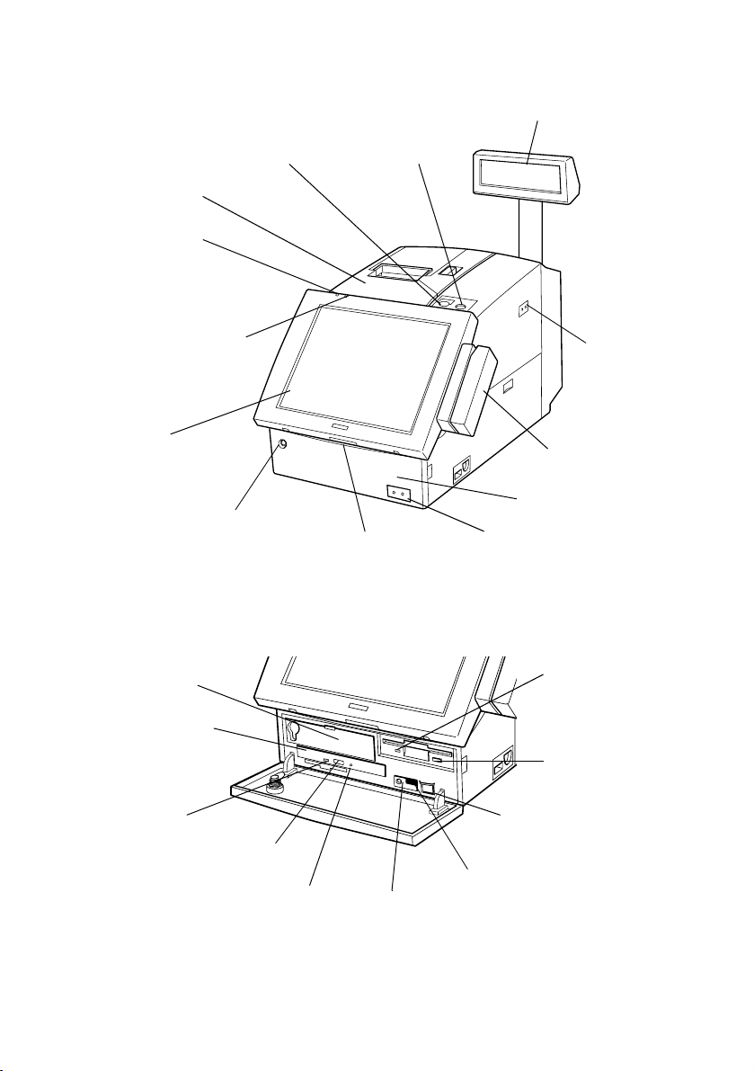
DM-LR104/DM-LR104SV/DM-LR104T
3
paper feed switch
2
printer unit (option)
1
power LED
13
HDD access LED
12
LCD unit (option)
5
customer display (option)
4
key lock
6
main power
switch
7
MSR unit (option)
11
front cover key lock
CD-ROM (OI-R06)
22
HDD slot
21
CD-ROM drive
20
CD-ROM
eject button
19
CD-ROM access LED
A
18
CD-ROM eject hole
10
lock switch
17
reset switch
8
front cover
9
soft power switch
14
FDD access LED
15
FDD eject button
9
soft power switch
16
speaker volume
Page 3
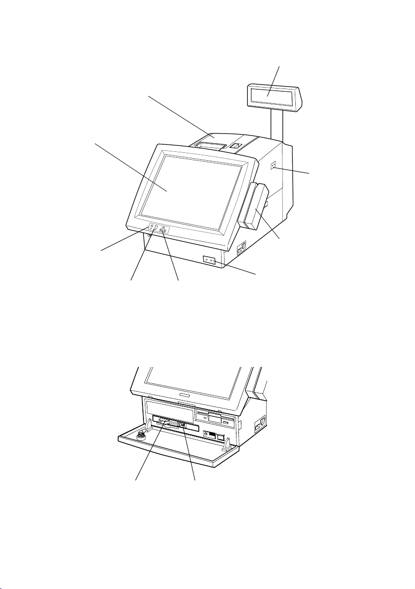
2
DM-LR121SV
printer unit (option)
12
LCD unit (option)
5
customer display (option)
6
main power
switch
Front CompactFlash Adapter (OI-R07)
24
Front CompactFlash Adapter
1
power LED
13
HDD access LED
23
LCD brightness
adjustment buttons
25
eject button
7
MSR unit (option)
9
soft power switch
B
Page 4
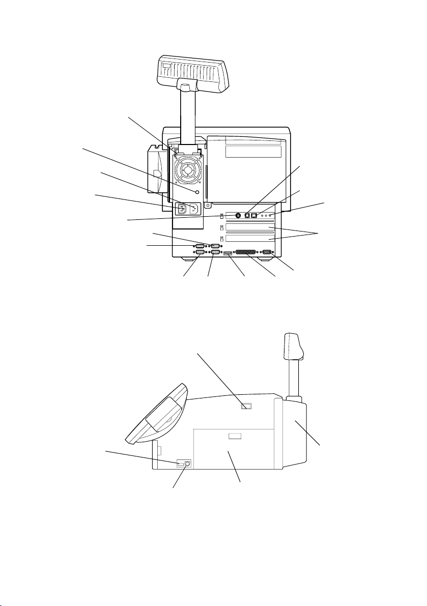
Rear View
33
DM-D (at the base
of the customer
display)
32
Fuse
31
AC outlet
30
AC inlet
29
TM power supply
connector
COM5
COM6
COM2 COM1
USB
26
DKD connector
27
Ethernet connector
CRT
LPT
LAN LEDs
28
PCI slots
Side View
C
USB
6
main power switch
36
keyboard/mouse
connector
34
rear cover
35
side cover
Page 5

English
All rights reserved. No part of this document may be reproduced, stored in a retrieval system, or transmitted in any
form or by any means, electronic, mechanical, photocopying, recording, or otherwise, without the prior written
permission of Seiko Epson Corporation. No patent liability is assumed with respect to the use of the information
contained herein. While every precaution has been taken in the preparation of this document, Seiko Epson
Corporation assumes no responsibility for errors or omissions. Neither is any liability assumed for damages resulting
from the use of the information contained herein.
Neither Seiko Epson Corporation nor its affiliates shall be liable to the purchaser of this product or third parties for
damages, losses, costs, or expenses incurred by purchaser or third parties as a result of: accident, misuse, or abuse of
this product or unauthorized modifications, repairs, or alterations to this product, or (excluding the U.S.) failure to
strictly comply with Seiko Epson Corporation’s operating and maintenance instructions.
Seiko Epson Corporation shall not be liable against any damages or problems arising from the use of any options or
any consumable products other than those designated as Original Epson Products or Epson Approved Products by
Seiko Epson Corporation.
EPSON and ESC/POS are registered trademarks of Seiko Epson Corporation.
Intel and Celeron are registered trademarks of Intel Corporation.
IBM, PC/AT, and PS/2 are registered trademarks of International Business Machines Corporation.
Microsoft and Windows are registered trademarks of Microsoft Corporation.
CompactFlash is a trademark of SanDisk Corporation.
General Notice: Other product and company names used herein are for identification purposes only and may be
trademarks of their respective companies.
NOTICE: The contents of this manual are subject to change without notice. Please contact us for the latest
information.
Copyright © 2000, 2002 by Seiko Epson Corporation, Nagano, Japan.
EMC and Safety Standards Applied
Product Name: IM-310
Type Name: M156A
The following standards are applied only to the units
that are so labeled.
Europe: CE marking
North America: EMI: FCC/ICES-003 Class A
Japan: EMC: VCCI Class A
Oceania: EMC: AS/NZS 3548
Safety: UL 1950/ CSA C22.2
No. 950
JEIDA 52
WARNING
The connection of a non-shielded printer interface
cable to this device will invalidate the EMC standards
of this device.
You are cautioned that changes or modifications not
expressly approved by SEIKO EPSON Corporation
could void your authority to operate the equipment.
UL1950
AC CORD
Detachable, maximum 4.5m (14.76ft) long.
Listed, CN, rated minimum 125 V, 7A, having a
Type SPT-2, SVT or SJT flexible cord.
One end terminates with a parallel blade,
grounding, molded-on, attachment plug with a
15 A, 125 V (NEMA 5-15P) for 100-120 V input,
15 A, 250 V (NEMA 6-15P) for 200-240 V input
configuration; other end terminates with
molded-on appliance coupler.
CE Marking
The unit conforms to the following Directives and
Norms:
Directive 89/336/EEC EN 55022 Class A
Directive 73/23/EEC Safety: EN 60950
EN 55024
IEC 61000-4-2
IEC 61000-4-3
IEC 61000-4-4
IEC 61000-4-5
IEC 61000-4-6
IEC 61000-4-11
EN 61000-3-2
EN 61000-3-3
WARNING
This is a Class A product. In a domestic environment
this product may cause radio interference in which
case the user may be required to take adequate
measure s.
CAUTION:
Connecting an outdoor overhead LAN cable
directly to your product may lead to lightning
damage. If you need to connect such a cable
to your product, the cable must be protected
against an electrical surge between the cable
and your product. You should avoid connecting
your product to a non-surge protected outdoor
overhead LAN cable.
IR-310 User’s Manual 1
Page 6
English
FCC Compliance
Statement For American
Users
This equipment has been tested and found to comply
with the limits for a Class A digital device, pursuant
to Part 15 of the FCC Rules. These limits are designed
to provide reasonable protection against harmful
interference when the equipment is operated in a
commercial environment.
This equipment generates, uses, and can radiate radio
frequency energy and, if not installed and used in
accordance with the instruction manual, may cause
harmful interference to radio communications.
Operation of this equipment in a residential area is
likely to cause harmful interference, in which case the
user will be required to correct the interference at his
own expense.
For Canadian Users
This Class A digital apparatus complies with
Canadian ICES-003.
For Taiwanese Users
Safety Precautions
This section presents important information intended to ensure
safe and effective use of this product. Read this section carefully,
and store it in an accessible location.
WARNING:
Turn off the main power switch immediately and unplug the power cord
if the IR-310 produces smoke, a strange odor, or unusual noise.
Continued use may lead to fire or electric shock. Contact your dealer or
an EPSON service center for advice.
Never attempt to repair this product yourself. Improper repair work can
be dangerous.
Never disassemble or modify this product. Tampering with this product
may result in injury, fire, or electric shock.
Never insert or disconnect the power plug with wet hands. Doing so
may result in severe shock.
Do not allow foreign objects to fall into this product. Penetration by
foreign objects may lead to fire or shock.
If water or other liquid spills into this product, turn off the side power
switch, unplug the power cord immediately, and then contact your
dealer or an EPSON service center for advice. Continued usage may
lead to fire or shock.
Always supply power directly from a standard domestic power outlet.
Do not place multiple loads on the power outlet (wall outlet).
Overloading the outlet may lead to fire.
2 IR-310 User’s Manual
Page 7
English
The equipment must be installed near the electrical outlet, and the
outlet must be easily accessible.
Do not attempt to open or disassemble the internal Vanadium-Lithium
battery. This could result in burns or release of hazardous chemicals.
Do not charge or leave the internal Vanadium-Lithium battery in a hot
place such as near a fire or on a heater because it could overheat and
ignite.
When you dispose of the internal Vanadium-Lithium battery, insulate it
by wrapping the terminals with tape. Mixing the battery with other
metals or batteries may lead to fire, heat, or explosion.
Be sure your power cord meets the relevant safety standards and
includes a power system ground terminal (PE terminal).
Handle the power cord with care. Improper handling may lead to fire or
shock.
Do not modify or attempt to repair the cord.
Do not place any object on top of the cord.
Avoid excessive bending, twisting, and pulling of the cord.
Do not place the cord near heating equipment.
Check that the plug is clean before plugging it in.
Be sure to push the prongs all the way in.
Do not use a damaged cord.
Regularly remove the power plug from the outlet and clean the base of
the prongs and between the prongs. If you leave the power plug in the
outlet for a long time, dust may collect on the base of the prongs,
causing a short and fire.
CAUTION:
Do not connect cables other than those specified in this manual. Doing
so may result in fire or improper operation.
Do not connect the unit to electrical outlets that are close to devices
that generate voltage fluctuations or electrical noise. In particular, stay
clear of devices that use large electric motors.
Always connect the power cable to the IR-310 before plugging it into
the wall outlet.
Be sure to push the plug of the power cord all the way into the AC inlet
of this product. The plug should make contact with the back of the inlet.
When disconnecting the power cable, hold the plug firmly. Do not tug
on the cord itself.
Be sure to set this product on a firm, stable, horizontal surface. The
product may break or cause injury if it falls.
IR-310 User’s Manual 3
Page 8

English
Do not use the unit in locations subject to high humidity or dust levels.
Excessive humidity and dust may cause equipment damage, fire, or
shock.
Do not use the product where inflammable fumes of gasoline, benzine,
thinner or other inflammable liquids may be in the air. Doing so may
cause an explosion or fire.
Do not place heavy objects on top of this product. Equipment may fall
or collapse, causing breakage and possible injury.
To ensure safety, unplug this product before leaving it unused for an
extended period.
Do not drop, bump, or otherwise subject this product to strong vibration
or impact.
Do not block the openings on this product. They are provided for the
ventilation necessary to ensure reliable operation and protection from
overheating.
Be sure to attach all covers after setup. If they are not attached, foreign
matter may enter this product and it may not operate correctly.
Never clean the product with thinner, benzene, alcohol, or other such
solvent.
Do not use this product with any voltage other than the specified one.
Doing so may lead to fire.
When a power cable for the TM printer is connected, do not short-circuit
its connector pins.
Do not insert fingers or foreign matter into the CD-ROM disk tray or
openings. Doing so may lead to fire, shock, or injury.
Do not insert fingers or foreign matter into the Front CompactFlash
Adapter opening. Doing so may cause equipment damage.
Never hold this product by the rear cover, the front panel, or the
CD-ROM disk tray. They cannot support the weight of the product, so it
may fall onto the floor.
Make sure that the total power requirements of all devices receiving
power from this product do not exceed the power limitation. See the
specifications for more detailed information.
Be sure to use this product with all covers attached.
Be careful not to cut your finger on any edge of the unit.
Be sure to use EPSON supplied DIMMs, HDDs, CPUs, and KBs.
To get the latest information about which CompactFlash Memory Card
or Adapter or PCI board can be used with this product, contact your
EPSON dealer.
If you turn off the unit, wait longer than 10 seconds before you turn it on
again.
Be sure to attach the HDD cover when you use this product. If the cover
is not attached, the product may not operate correctly.
TM
4 IR-310 User’s Manual
Page 9
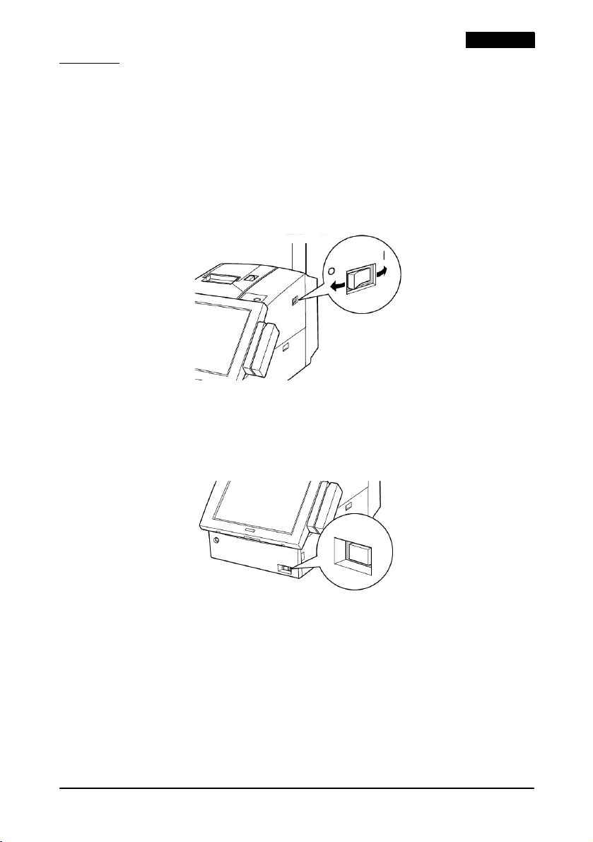
Power
When you use this product for the first time, turn on the main
power switch. The “O” mark indicates off, and the “|” mark
indicates on.
The main power switch should usually be kept on. Turn off the
unit’s main power switch only when attaching peripherals, before
transporting it, when it will not be used for an extended period of
time, or in the unlikely event that the unit produces strange noises
or smoke.
With the main power switch on, you can press the soft power
switch on the front of the unit to turn the unit on and off. The soft
power switch uses software to turn your system on and off, but
even when the unit is turned off with this switch, a small amount of
current is flowing.
English
When a problem in the unit causes the protection circuit to be used,
the soft switch does not work. If this happens, turn off the main
power switch and wait for about 10 minutes. Then turn on the
main power switch and then the soft switch.
Power Off
You usually turn off power through your software. The power off
procedure varies depending on the operating system and BIOS
used.
IR-310 User’s Manual 5
Page 10
English
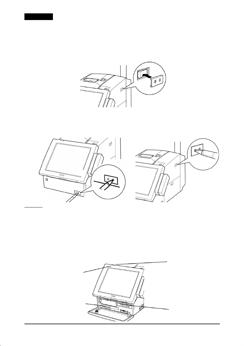
Power Switch Covers
This product includes 2 switch covers that prevent the unit from
being turned on or off accidentally. To install a switch cover, place
the switch cover over the switch, and press it into place.
When you have installed a switch cover, operate the switch by
pushing a thin object, such as a pencil, through the holes in the
switch cover.
LEDs
The LCD and the keyboard units have 2 LEDs each, and the FDD
and CD-ROM have 1 each. The place and number of LEDs differ
depending on the options installed. Two examples are shown.
❏
With the 84 Keyboard unit and the DM-LR104 / DM-LR104SV
or DM-LR104T LCD unit installed:
HDD LED
Power
LED
CD-ROM
LED
6 IR-310 User’s Manual
FDD LED
Page 11
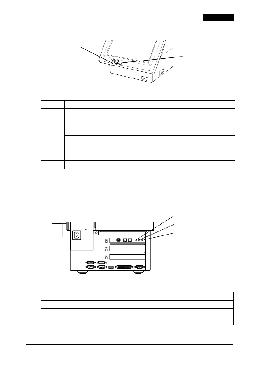
❏ With the DM-LR121SV LCD unit installed:
Power LED
HDD LED
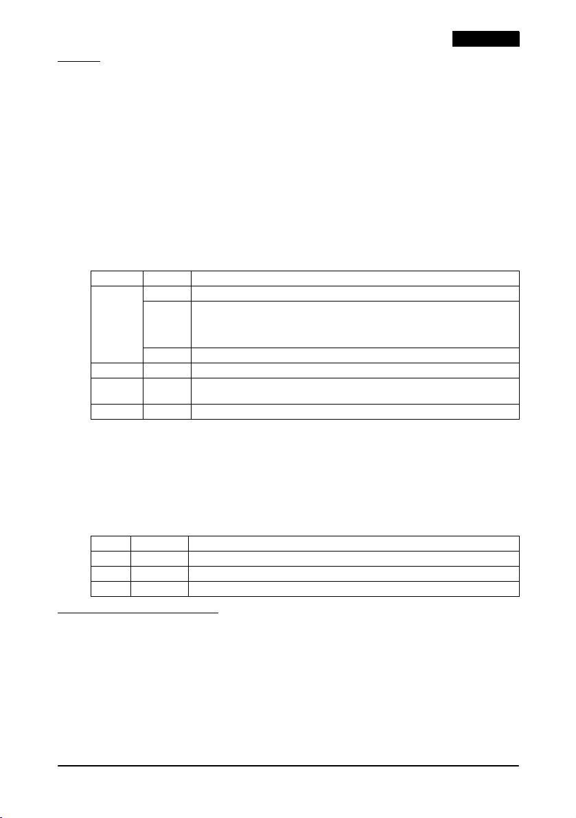
These LEDs have the following meaning:
LED Color Meaning
Power
LED
HDD Green HDD is being accessed.
CD-ROM Orange CD-ROM is being accessed. (No LED if CD-ROM drive is not installed.)
FDD Green FDD is being accessed.
Green Power is turned on (during normal operation).
Flashing
green or
orange
Off Power is off.
Backup is in progress using the power from the battery unit (OI-R03).
Rear Side LEDs
There are 3 LEDs on the rear side showing the access state to the
network using the LAN. They are on only when the LAN is being
accessed.
ACT LED
100 LED
10 LED
English
These LEDs have the following meaning:
LED Color Meaning
ACT Green Accessing the network. (Transmitting and receiving)
100 Green Connected to 100BASE-TX.
10 Green Connected to 10BASE-T.
IR-310 User’s Manual 7
Page 12
English
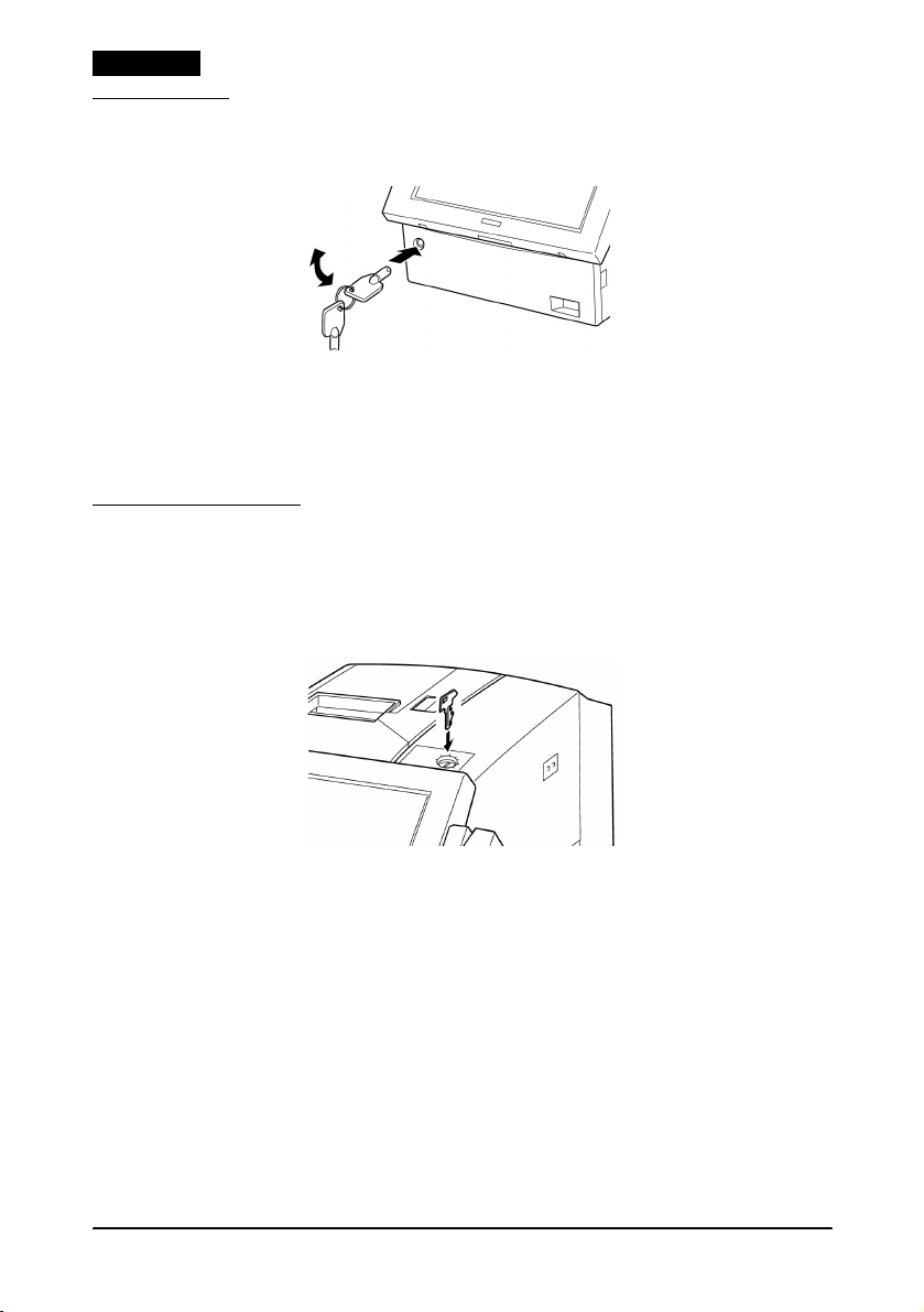
Front Key
The front key is for the cover lock on the front panel.
With the front panel locked, the floppy disk, CompactFlash card,
and CD-ROM can be removed only by a person with a front key.
Insert the front key into the cover lock hole, and turn it while
slightly pushing in to lock or unlock the front panel.
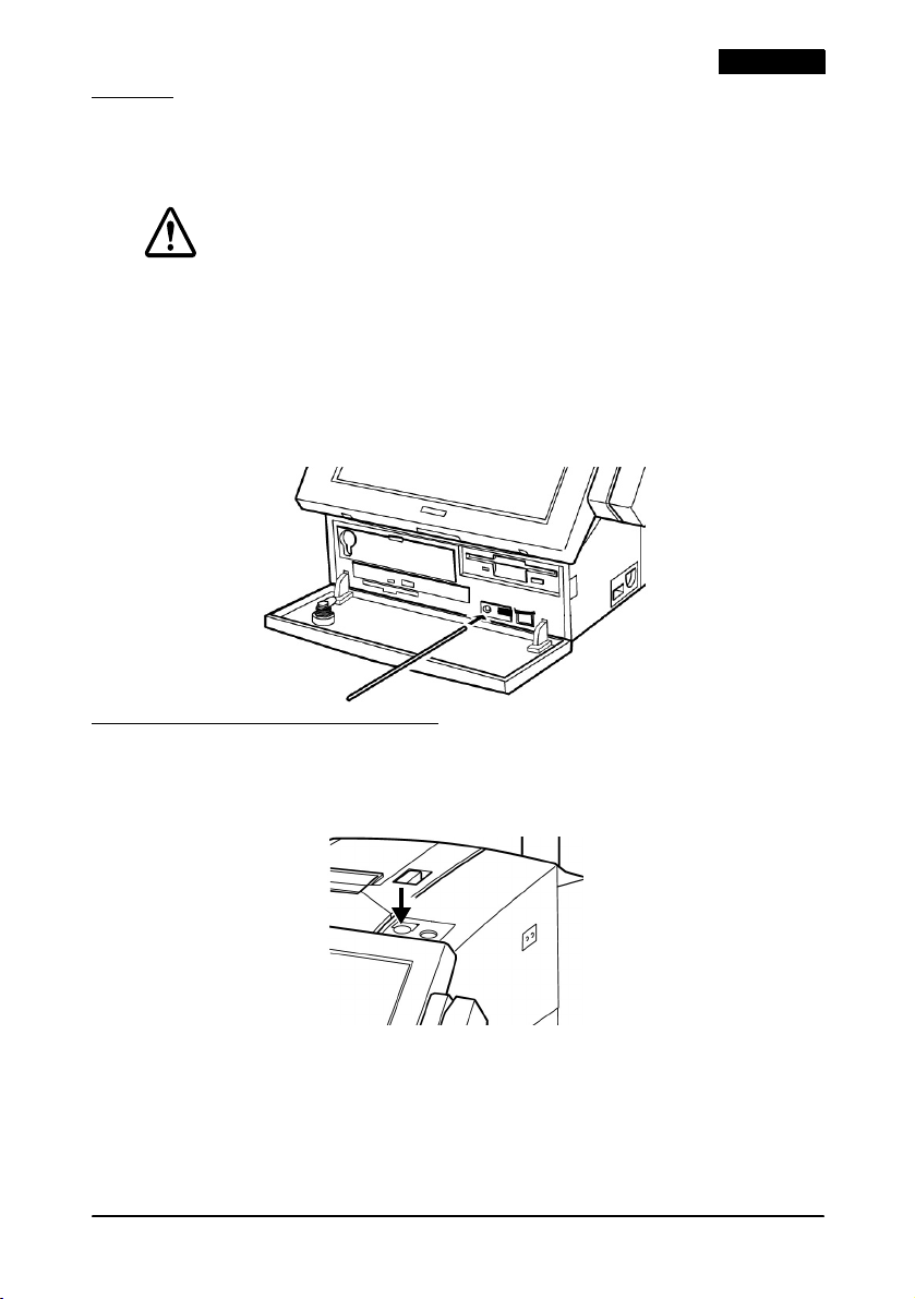
Key Lock Keys
A set of 5 Key Lock keys is provided. Each key allows the user to
access the function level you define for that key position. The Key
Lock keys are used by inserting them into the lock on top of the
IR-310.
The Key Lock keys place restrictions on the functions that can be
used by the operator. The Key Lock key can be turned to
6 positions (from 1 to 6). Each key can be given a different access
range to prevent use of higher functions by unauthorized users.
8 IR-310 User’s Manual
Page 13
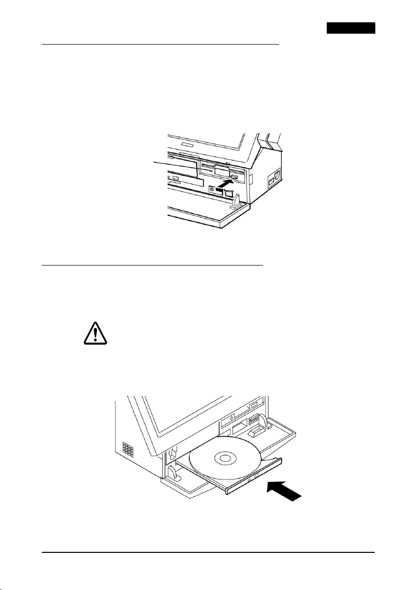
Inserting and Removing a Floppy Disk
Insert the floppy disk with the label side up in the floppy disk
drive. When the floppy disk is inserted correctly, the eject button
pops out.
To remove a floppy disk, make sure the access LED of the floppy
disk drive is off. Then press the eject button.
FDD LED
Take out the floppy disk carefully.
Inserting and Removing a CD-ROM
1. Press the eject button of the CD-ROM drive; the tray comes out.
2. Put the CD-ROM with the label side up in the tray.
English
CAUTION:
Push the CD-ROM down slightly to ensure that it is firmly set in the
tray. Otherwise the CD-ROM may be damaged.
3. Gently push the tray into the CD-ROM drive.
To remove a CD-ROM, follow these steps.
1. Check that the access LED of the CD-ROM is off.
IR-310 User’s Manual 9
Page 14
English
2. Press the eject button; the tray comes out slightly.
3. Pull the tray out fully, and remove the CD-ROM carefully.
CD-ROM Emergency Ejection
When the CD-ROM drive does not function properly, you can
remove the CD-ROM by following the steps below:
1. Turn off the IR-310.
2. Insert a small thin object, such as an extended paper clip, in the
CD-ROM eject hole.
3. The disk tray pops out slightly; then pull it out gently.
CompactFlash Cards
Note:
In some models of the IR-310, access to the CompactFlash card is inside
the case of the IR-310; however, the instructions here describe only the use
of IR-310 units with the Front CompactFlash Adapter.
Handling CompactFlash Cards
CompactFlash cards are composed of precision electronic
components. Follow the cautions below to prevent incorrect
operation or failure of the cards.
CAUTION:
Do not touch the terminals of a CompactFlash card with your fingers or
any metal object because electrostatic discharge may damage
internal components. Before touching a card, discharge your
electrostatic charge by touching a metal fixture. Failure to do so may
damage the system.
10 IR-310 User’s Manual
Page 15
®
Unless you are using BaySwap
CompactFlash card while the system is on. If you have installed
BaySwap, refer to the BaySwap operation procedure below. Failure to
observe these precautions may result in system damage.
Do not bend or drop the card, and protect it from impact.
Protect the card from excessive heat, moisture, and direct sunlight
during use and storage.
under Windows NT, never remove the
Inserting and Removing CompactFlash Cards
Observe the following requirements when inserting and removing
CompactFlash cards.
When the power is on BaySwap not in use: Inserting and removing not possible.
BaySwap in use: Inserting and removing possible.
When the power is off Inserting and removing possible.
See “Using BaySwap” for details on the procedure for inserting and
removing CompactFlash cards when BaySwap is in use.
BaySwap can be used only with Windows NT.
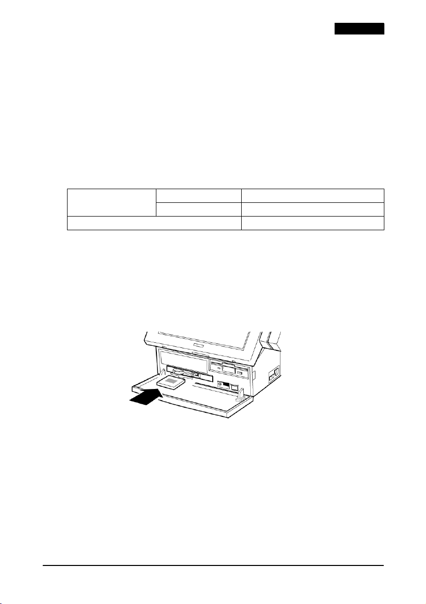
Inserting a CompactFlash Card
Insert the CompactFlash card face up firmly into the slot to set it in
place.
English
IR-310 User’s Manual 11
Page 16
English
Removing a CompactFlash Card
Press the eject button firmly. The CompactFlash card is ejected
slightly from the slot so you can remove it.
Using BaySwap
If you are running Windows NT with the BaySwap program
installed, read these instructions.
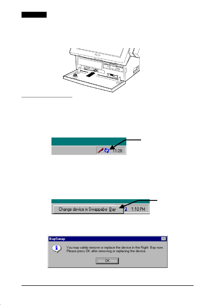
The BaySwap icon resides in the task bar, as shown below, when
Windows NT is booted.
BaySwap
Operation Procedure
Make sure that reading or writing is not being performed on the
CompactFlash card before removing it.
1. Click the icon in the task bar, and then click [Change device in
Swappable Bay].
2. The following dialog box is displayed. Insert or remove the
card at this point.
3. Click OK once the card has been inserted or removed.
12 IR-310 User’s Manual
Page 17
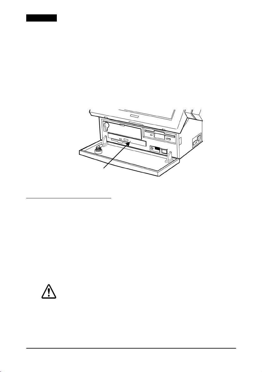
Reset
Reset restarts the computer while the power is on. Reset is
necessary only when software has entered an endless loop.
CAUTION:
Do not press the reset switch unless the system fails to respond.
When the system is reset, all data in memory is lost.
Perform a reset by following the procedure below.
1. Open the front panel. If the front panel is locked, unlock it
using the front key.
2. Push the reset switch with a pointed object such as a pen.
English
Paper Feed with a Printer
If a printer is connected to the IR-310, press the paper feed button
to feed paper.
IR-310 User’s Manual 13
Page 18
English
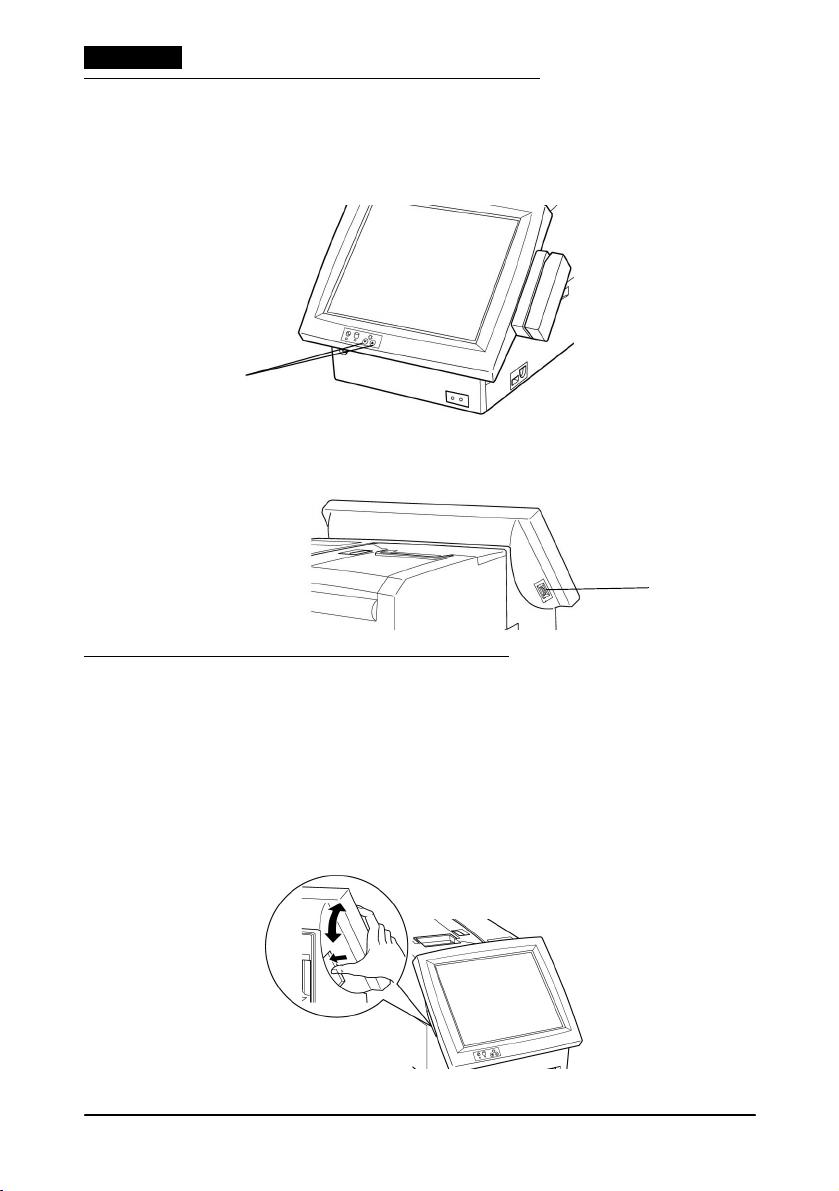
LCD Brightness/Contrast Adjustment
You can adjust LCD brightness for the DM-LR121SV or
DM-LR104T or contrast for the DM-LR104/DM-LR104SV by using
the controls marked A and B below:
DM-LR121SV LCD
A
DM-LR104/DM-LR104SV/DM-LR104T LCD
B
LCD/Keyboard Angle Adjustment
The angle of the LCD/keyboard unit is adjustable, but the
adjusting positions differ depending on the LCD unit. Follow these
steps to change the angle.
DM-LR121SV LCD unit
1. Adjust the angle of the LCD unit while pressing the lock lever
on the left side of the LCD unit.
14 IR-310 User’s Manual
Page 19
English
2. When you release the lock lever, the angle is fixed.
3. Move the LCD unit slightly up and down to firmly fix it.
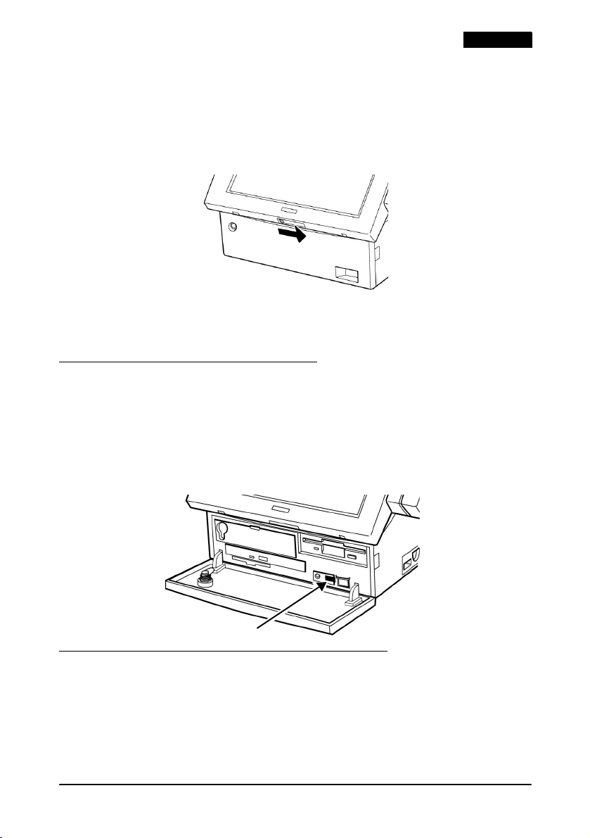
DM-LR104/DM-LR104SV/DM-LR104T LCD unit and DM-KR084 Keyboard
1. Slide the LCD/keyboard unit lock switch to the unlock
position.
2. Adjust the angle to the position you want.
3. Set the lock switch to the lock position again.
Speaker Volume Adjustment
Adjust speaker volume by following the procedure below.
1. Open the front panel. If the front panel is locked, unlock the
front panel using the front key.
2. Turn the volume control to the left to turn down the volume.
Turn it to the right to turn up the volume.
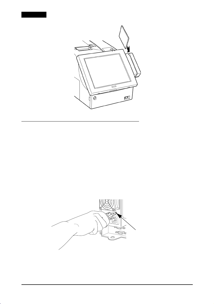
How to Read a Magnetic Stripe Card
When you attach an MSR (Magnetic Stripe Reader) unit, magnetic
stripe cards can be read.
Hold the card as shown below, and pass it through the MSR unit.
IR-310 User’s Manual 15
Page 20
English
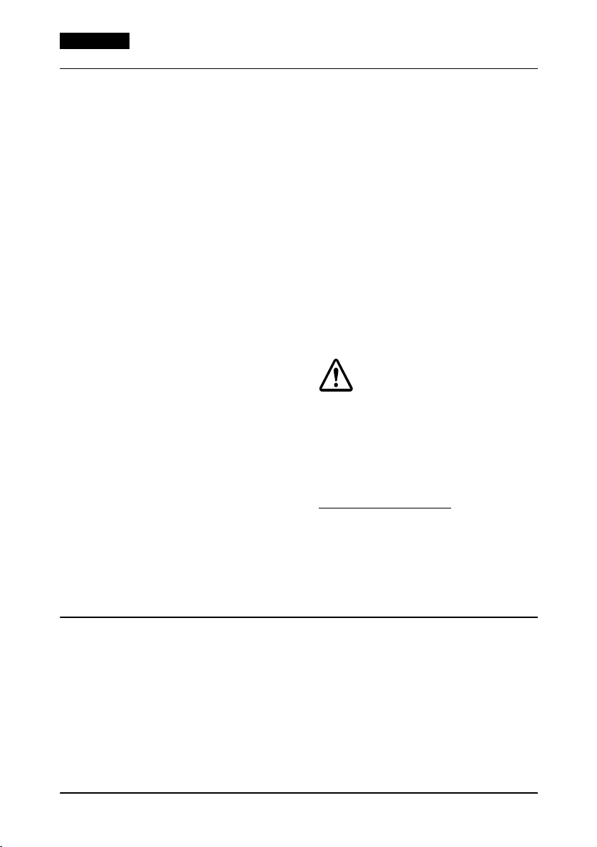
Changing the AC Outlet Circuit Fuse
An overcurrent from the AC outlet can blow the fuse. Follow the
steps below to replace it.
1. Turn off the equipment connected to the AC outlet and unplug
the power cable from the AC outlet.
2. Turn off the IR-310 and unplug the power cable from the AC
inlet.
3. Using a flathead screwdriver, push and twist the fuse holder to
remove it.
4. Replace the old fuse with an new one and replace the fuse
holder.
16 IR-310 User’s Manual
Page 21
English
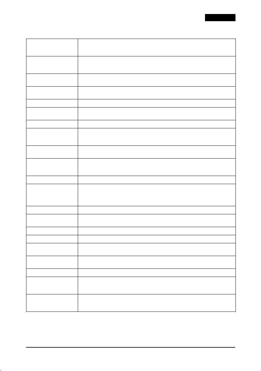
IR-310 specifications
CPU Intel: Celeron
Power management IR-310 BIOS supports Advanced Power Management (APM).
DIMM sockets Two 168-pin DIMM sockets are provided on the main board.
System ROM System BIOS and video BIOS are registered in 256 KB flash ROM on the main
Pentium
370-Pin Socket
APM controls power management function for the CPU, video, hard disk drive,
and so on.
3.3V SDRAM / maximum 256 MB.
board.
ROM for POS keys 128 KB flash ROM is used
Clock/calendar Real-time clock, calendar, and CMOS RAM are contained in the RTC chip;
backed up by a Vanadium-Lithium battery
Chipset Intel 440BX
NVRAM (option) Battery-backed 32 KB SRAM. When NVRAM board is detached from the IR-310,
Video controller Intel 69000 VRAM 2 MB, 1024
Sound board (option) FM tone generator, 16-bit PCM, software Wave Table. No External Line in/out or
the contents of the NVRAM will be lost. When a CompactFlash Memory Card is
installed, NVRAM is not available.
640
Microphone. Volume controlled by a volume control on the front of the IR-310.
Sound is output from the mono speaker on the left side.
Parallel 25-pin D-Sub female connector. Port can be defined as ECP or EPP.
Serial 9-pin D-sub male connector
internal printer/DM display (COM3) and touch panel (COM4). When either
COM5 or COM6 is used, an unneeded device (such as Parallel, USB, or Sound)
must be set to unused by BIOS setup.
Ethernet 10BASE-T or 100BASE-TX Wake Up on LAN available
Keyboard/mouse 6-pin miniature-DIN female connector (PS/2 type). Use branch (Y cable) to
connect both keyboard and mouse.
Video 15-pin SD-Sub female connector. Analog RGB display can be connected.
USB Type A 4-pin
Drawer (DKD) 6-pin. When a printer is attached, a cash drawer can be connected to this
PCI slot PCI slot
interface.
12 mm {0.47"}, H: solder side 10 mm {0.39"} I/O expansion slots.
Floppy disk drive 3.5-inch floppy disk drive with a 720 KB or 1.44 MB storage capacity.
Hard disk drive A unit of 3.5"-type Hard Disk (maximum thickness: 25.4 mm {1"}) or 2 units of the
CD-ROM drive (option) 12.7 cm optional CD-ROM drive. 24
2.5"-type Hard Disk (maximum thickness: 9.5 mm {0.37"}, for a unit : 12.7 mm {0.5"}
maximum) can be attached. IDE interface / Ultra DMA/33.
CompactFlash Adapter is installed.
Music CD cannot be played with optional sound board.
TM
366 / 433 / 733 MHz Secondary cache 128 KB built-in
III 700 MHz Secondary cache 256 KB built-in
×
×
480 (16 M colors). Color available only when a CRT is connected.
×
2. One USB at the rear side and one on the right side.
×
2. 32-bit, half-size: 135 × 101 mm {5.3 × 4.0"} (L × W), H: Parts side:
768 (64 K colors), 800 × 600 (16 M colors),
×
2. Six serial ports supported. 2 ports used for
×
. Cannot be installed when a Front
IR-310 User’s Manual 17
Page 22
English
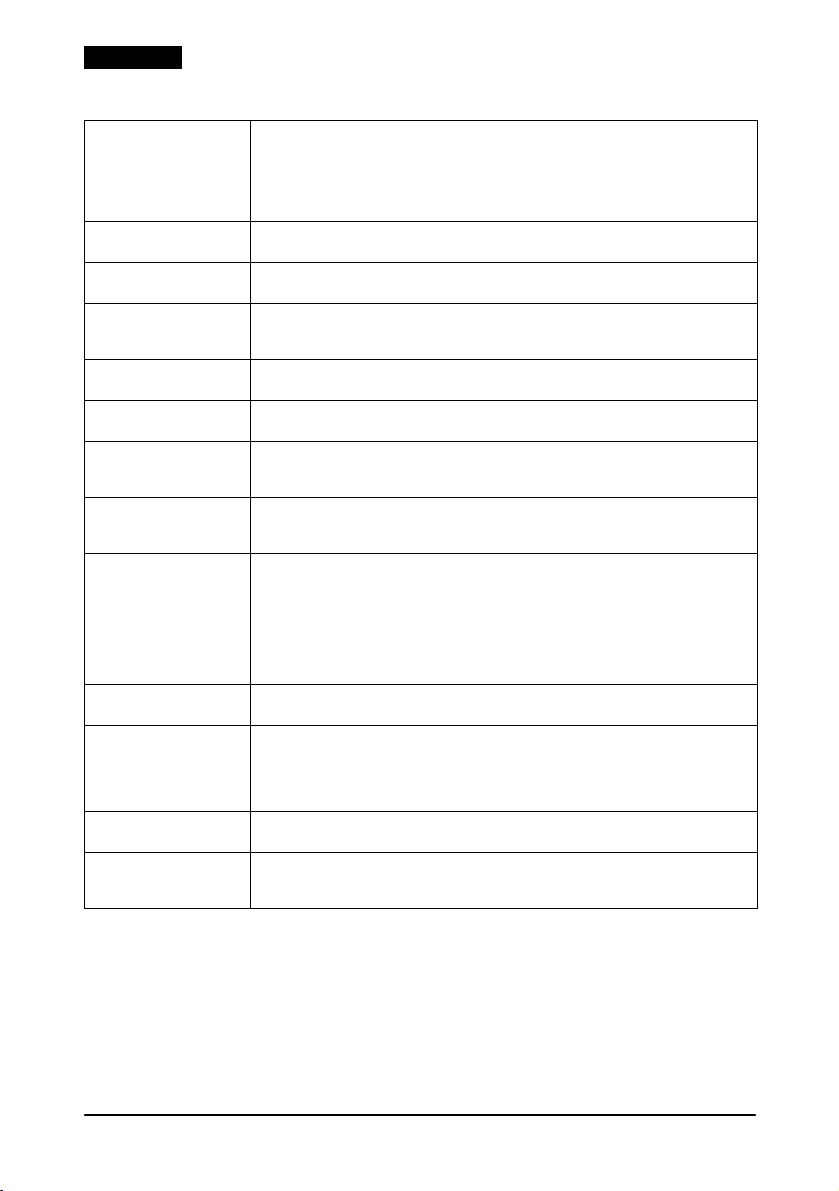
IR-310 specifications (continued)
CompactFlash (option)
2 types available:
CompactFlash
Memory Card
Front CompactFlash
Adapter
Main power switch On side of unit. Turns on and off the power from the power unit. Leave this
Soft power switch On front of unit. Turns power on/off. Also controls any device (such as a
RESET switch Push-type switch to reset this product; accessible using a pointed object like a
LEDs The power and HDD LEDs are on the 84-Keyboard unit or the LCD unit. The FDD
BIOS setup Configures this product, saving settings to CMOS; accessible by pressing Delete
Device diagnostics Helps you to isolate communication problems this product or connected
Battery pack (option) Optional NiCd battery is provided for the system.
Lithium battery The system is equipped with 2 Vanadium-Lithium rechargeable batteries for
Power supply 100 ~ 240 V, 50 ~ 60 Hz, 6 ~ 4 A / Approximately 265 W (except the power for
AC outlet Connector: 3-pin female type.
Dimensions
(W
×
L × H)
Environmental
conditions
True IDE mode, TYPE I (thickness: 3.3 mm {0.13"}) and TYPE II (thickness: 5.0 mm
{0.20"}) are available. When using CF+ card, make sure that it is available in
True IDE mode. When a CompactFlash Memory Card is installed, NVRAM
cannot be installed. When the Front CompactFlash Adapter is installed, a
CD-ROM drive cannot be installed.
switch ON for normal use.
monitor) connected to the AC outlet on the power supply.
ball-point pen. Devices attached to COM ports are not reset when you reset
this product.
and the CD-ROM drive have their own LEDs. The LAN LEDs are on the rear side.
when you turn on this product.
devices may be having. You can start the device diagnostics by pressing F10
during the POST (Power On Self Test.)
Charging method: Trickle charge (when main power switch is on)
Charging time: 32 hours
real-time clock, CMOS, and optional NVRAM backup. Be sure to charge
batteries before using this product.
Charging method: Constant-voltage charge 3.4 V ± 0.15 V
Charging time: 40 hours
Backup time: 40 days (full charge; when NVRAM is connected.)
AC outlet).
Output voltage/frequency: Same as the AC input.
Output ratings: 3 A
The Output of the AC outlet is interlocking with the power on/off control in the
IR-310.
With rear cover: 252
Without rear cover: 252
Condition: Operating range Storage range
Temperature: 5 to 35°C {41 to 95°F} –10 to 50°C {14 to 122°F}
Humidity (RH): 30 to 80% non-condensing 30 to 90% non-condensing
(when main power switch is on)
200 days (full charge; when NVRAM is not connected.)
×
457 × 261 mm {9.9 × 18.0 × 10.3"}
×
386 × 261 mm {9.9 × 15.2 × 10.3"}
18 IR-310 User’s Manual
Page 23

IR-310
Bedienungsanleitung
Deutsch
Deutsch
Dieses Handbuch ist in 7 Abschnitte unterteilt, einen pro Sprache. Die meisten Abbildungen sind im ersten Abschnitt
Abbildungen
zu finden und werden nicht wiederholt. Jeder Abschnitt enthält jedoch Seitenverweise auf die Abbildungen.
1. Netz-LED 19. CD-ROM Zugriffs-LED
2. Druckereinheit (Option) 20. CD-ROM Auswurfknopf
3. Papiereinzugsschalter 21. CD-ROM Laufwerk
4. Schloss 22. HDD-Schlitz
5. Kundenanzeige (Option) 23. LCD-Helligkeitseinstellknöpfe
6. Hauptschalter 24. CompactFlash Adapter, vorn
7. MSR-Einheit (Option) 25. Auswurfknopf
8. Frontabdeckung 26. DKD-Anschluss
9. Ein/Aus-Schalter 27. Ethernet-Anschluss
10. Sperrschalter 28. PCI-Steckplätze
11. Schloss für Frontabdeckung 29. TM-Netzgerätanschluss
12. LCD-Einheit (Option) 30. Wechselstromeingang
13. HDD-Zugriffs-LED 31. Wechselstromausgang
14. FDD-Zugriffs-LED 32. Sicherung
15. FDD-Auswurfknopf 33. DM-D (am Sockel der Kundenanzeige)
16. Lautsprechervolumen 34. Rückseitenabdeckung
17. Rücksetzschalter 35. Seitenwand
18. CD-ROM Auswurföffnung 36. Tastatur-/Mausanschluss
Alle Rechte vorbehalten. Diese Veröffentlichung darf ohne ausdrückliche schriftliche Genehmigung der Seiko Epson
Corporation nicht reproduziert, in einem Abrufsystem gespeichert oder in beliebiger Form und auf jedwede Weise
übermittelt werden, weder durch Fotokopieren, Aufzeichnen, noch auf elektronische, mechanische oder sonstige
Weise. Für die hierin enthaltenen Informationen wird keine Patenthaftung übernommen. Obgleich bei der
Zusammenstellung dieser Anleitung mit Sorgfalt vorgegangen wurde, übernimmt die Seiko Epson Corporation
keine Verantwortung für Fehler und Auslassungen. Zudem wird keine Haftung übernommen für Schäden, die aus
der Verwendung der hierin enthaltenen Informationen entstehen.
Weder die Seiko Epson Corporation noch ihre Tochtergesellschaften sind dem Käufer dieses Produkts oder
Drittparteien gegenüber für Schäden, Verluste, Kosten oder Ausgaben haftbar, die für den Käufer oder etwaige
Drittparteien aufgrund von Unfall, Missbrauch oder Zweckentfremdung dieses Produkts, nicht autorisierten
Modifikationen, Reparaturen oder Produktumbauten sowie (mit Ausnahme USA) aufgrund des Versäumnisses
anfallen, die Bedienungs- und Wartungsanleitungen der Seiko Epson Corporation genau einzuhalten. In Betrieb.
Die Seiko Epson Corporation ist nicht haftbar für Schäden oder Probleme, die bei Verwendung von Optionen oder
Verschl eißteilen auftreten, die nicht als Original-Epson-Produkte oder von der Seiko Epson Corporation zugelassener
Epson Produkte gelten.
EPSON und ESC/POS sind eingetragene Warenzeichen der Seiko Epson Corporation.
Intel und Celeron sind eingetragene Warenzeichen der Intel Corporation.
IBM, PC/AT und PS/2 sind eingetragene Warenzeichen der International Business Machines Corporation.
Microsoft und Windows sind eingetragene Warenzeichen der Microsoft Corporation.
CompactFlash ist ein Warenzeichen der SanDisk Corporation.
Allgemeiner Hinweis: Weitere hierin verwendete Produkte und Firmennamen dienen nur Identifikationszwecken
und sind unter Umständen Warenzeichen der jeweiligen Firmen.
HINWEIS: Änderungen dieser Betriebsanleitung ohne Vorankündigung vorbehalten. Für die aktuellsten
Informationen setzen Sie sich bitte mit uns in Verbindung.
Copyright © 2000, 2002 Seiko Epson Corporation, Nagano, Japan.
IR-310 19
Page 24
Deutsch
Geltende EMC und Sicherheitsnormen
Produktname: IM-310
Modellname: M156A
Die folgenden Normen gelten nur für entsprechend
gekennzeichnete Geräte.
Europa: CE-Zeichen
Nordamerika: EMI: FCC/ICES-003 Klasse A
Japan: EMC: VCCI Klasse A
Ozeanien: EMC: AS/NZS 3548
Sicherheit: UL 1950/CSA C22.2
No. 950
JEIDA-52
WARNUNG
Beim Anschluss eines nicht isolierten
Druckerschnittstellenkabels an dieses Gerät
entspricht das Gerät nicht länger den EMC-Normen.
Sie werden darauf hingewiesen, dass Sie nach
Änderungen oder Modifikationen, die nicht
ausdrücklich von der SEIKO EPSON Corporation
zugelassen wurden, unter Umständen nicht länger
zur Bedienung des Geräts berechtigt sind.
UL1950
NETZKABEL
Abnehmbar, maximal 4,5 m lang.
CN-gepr üft, Nennaufnahme mindestens 125 V,
7 A, mit flexiblem Kabel des Typs SPT-2, SVT
oder SJT.
Das eine Ende weist einen Formstecker auf mit
Parallel-Anschlussstiften und Erdung, 15 A, 125 V
(NEMA 5-15P) für 100 - 120-V-Versorgung bzw.
15 A, 250 V (NEMA 6-15P) für 200 - 240 VEingangskonfiguration; am anderen Ende ist
ein Geräteformstecker befestigt.
CE-Zeichen
Der Drucker entspricht den folgenden Vorschriften
und Normen:
Direktive 89/336/EEC EN 55022 Klasse A
Direktive 73/23/EEC Sicherheit: EN 60950
EN 55024
IEC 61000-4-2
IEC 61000-4-3
IEC 61000-4-4
IEC 61000-4-5
IEC 61000-4-6
IEC 61000-4-11
EN 61000-3-2
EN 61000-3-3
WARNUNG
Dies ist ein Produkt der Klasse A. Bei Heimgebrauch
verursacht dieses Produkt unter Umständen
Radiointerferenzen, die vom Benutzer durch
entsprechende Maßnahmen zu beheben sind.
VORSICHT:
Beim Direktanschluss eines im Freien angebrachten
Überkopf-LAN-Kabels an das Produkt besteht
Beschädigungsgefahr durch Blitzschlag. Wenn ein
Kabel dieser Art an Ihr Produkt angeschlossen
werden muss, ist es erforderlich, zwischen dem Kabel
und dem Produkt eine
Überspannungsschutzvorrichtung anzubringen.
Schließen Sie das Produkt möglichst nicht an im
Freien angebrachte Überkopf-LAN-Kabel ohne
Überspannungsschutz an.
GERÄUSCHPEGEL
Gemäß der Dritten Verordnung zum
Gerätesicherheitsgesetz
(Maschinenlärminformations- Verordnung-3. GSGV)
ist der arbeitsplatzbezogene Geräusch-Emissionswert
kleiner als 70 dB(A) (basierend auf ISO 7779).
Sicherheitsmaßnahmen
In diesem Abschnitt finden Sie wichtige Informationen zum
sicheren und effektiven Gebrauch dieses Produkts. Bitte lesen Sie
diesen Abschnitt sorgfältig durch und heben Sie ihn an einem
leicht zugänglichen Ort auf.
20 IR-310 Bedienungsanleitung
Page 25

Deutsch
WARNUNG:
Schalten Sie das Gerät sofort aus und ziehen Sie den Netzstecker, wenn
Sie beim IR-310 Rauch bzw. ungewöhnliche Gerüche oder Geräusche
bemerken. Wenn das Gerät weiter verwendet wird, besteht Brand- und
Stromschlaggefahr. Benachrichtigen Sie Ihren Händler oder ein EPSON
Service Center.
Versuchen Sie niemals, dieses Produkt eigenständig zu reparieren.
Unsachgemäße Reparaturarbeiten können gefährlich sein.
Zerlegen oder modifizieren Sie dieses Produkt nicht. Unsachgemäße
Arbeiten an diesem Produkt können zu Verletzungen, Brand oder
elektrischen Schlägen führen.
Stecken Sie das Netzkabel niemals mit nassen Händen ein oder ziehen
es heraus. Dies kann zu einem schweren elektrischen Schlag führen.
Vermeiden Sie das Eindringen von Fremdobjekten in dieses Produkt. Beim
Eindringen von Fremdkörpern besteht Brand- und Stromschlaggefahr.
Wenn Wasser oder sonstige Flüssigkeiten in dieses Produkt eindringen,
ziehen Sie sofort das Netzkabel heraus und benachrichtigen Sie einen
Fachhändler oder Ihr SEIKO EPSON Service Center. Wenn das Gerät
weiter verwendet wird, kann dies einen Brand oder elektrische Schläge
verursachen.
Schließen Sie das Gerät direkt an eine normale Haushaltssteckdose an.
Verwenden Sie keine Tischsteckdosen an der Wandsteckdose. Eine
Überlastung der Steckdose kann einen Brand verursachen.
Schließen Sie das Gerät immer direkt an eine leicht zugängliche
Schukosteckdose an.
Versuchen Sie nicht, den internen Vanadium-Lithium-Akku zu öffnen
oder auseinanderzunehmen. Andernfalls besteht Gefahr von
Verbrennungen und der Freigabe von gefährlichen Chemikalien.
Halten Sie den internen Vanadium-Lithium-Akku von Hitze fern, wie z.B.
von Kaminfeuer und Heizgeräten, damit der Akku nicht überhitzt und
kein Feuer fängt.
Überkleben Sie die Pole des Vanadium-Lithium-Akkus vor dem
Entsorgen mit Klebeband. Durch Kontakt des Akkus mit anderen
Metallen oder Batterien besteht, Brand-, Hitzeentwicklungs- und
Explosionsgefahr.
Stellen Sie sicher, dass das Netzkabel den zutreffenden Sicherheitsnormen
entspricht und einen Erdungsleiter (Schutzkontakt) aufweist.
IR-310 Bedienungsanleitung 21
Page 26

Deutsch
Seien Sie vorsichtig bei der Handhabung des Netzkabels. Die
unsachgemäße Verwendung kann zu einem Brand oder einem
elektrischen Schlag führen.
Ändern oder reparieren Sie das Netzkabel nicht.
Stellen Sie keine Gegenstände auf das Kabel.
Vermeiden Sie übermäßige Biegungen, Drehungen oder Zugkräfte
am Kabel.
Verlegen Sie das Kabel nicht in der Nähe von Heizgeräten.
Sorgen Sie vor dem Einstecken des Steckers dafür, dass er sauber ist.
Sie die Pole des Steckers bis zum Anschlag in die Steckdose.
Verwenden Sie keine beschädigten Kabel.
Ziehen Sie den Netzstecker regelmäßig aus der Steckdose und reinigen
Sie den Sockel der Anschlussstifte und den Bereich zwischen den
Anschlussstiften. Wenn der Netzstecker lange Zeit in der Steckdose
verbleibt, kann sich am Sockel der Anschlussstifte Staub ansammeln und
es besteht Kurzschluss- und Brandgefahr.
VORSICHT:
Schließen Sie Kabel nur auf die in diesem Handbuch beschriebene
Weise an. Andere Kabelverbindungen können das Gerät beschädigen
und einen Brand verursachen.
Schließen Sie das Gerät nicht an Steckdosen an, die sich in der Nähe von
Geräten befinden, die Spannungsschwankungen und elektrische
Interferenzen erzeugen, insbesondere Geräte mit großen Elektromotoren.
Schließen Sie das Netzkabel STETS ZUERST am IR-310 an, ehe Sie es an
eine Wandsteckdose anschließen.
Stecken Sie das Ende des Netzkabels unbedingt bis zum Anschlag in
den Netzstromeingang dieses Produkts. Der Stecker muss Kontakt mit
dem hinteren Teil des Eingangs haben.
Ziehen Sie das Netzkabel nur am Stecker aus der Steckdose. Nicht am
Kabel selbst ziehen.
Stellen Sie dieses Produkt unbedingt auf einer festen, stabilen,
horizontalen Fläche auf. Das Produkt kann beim Fallen beschädigt
werden oder Verletzungen verursachen.
Verwenden Sie das Gerät nicht an Orten mit hohem Feuchtigkeits- oder
Staubgehalt. Eine übermäßige Feuchtigkeits- oder Staubentwicklung
kann das Gerät beschädigen oder einen Brand bzw. einen elektrischen
Schlag verursachen.
Verwenden Sie das Produkt nicht, wenn Gefahr besteht, dass die
Umgebungsluft mit brennbaren Dünsten von Benzin, Benzol,
Verdünnungsmitteln oder sonstigen brennbaren Flüssigkeiten
angereichert ist. Andernfalls besteht Explosions- und Brandgefahr.
Stellen Sie keine schweren Gegenstände auf dieses Produkt. Das Gerät
kann fallen oder beschädigt werden und dabei Gegenstände
beschädigen oder Personen verletzen.
22 IR-310 Bedienungsanleitung
Page 27

Deutsch
Aus Sicherheitsgründen ziehen Sie bitte den Netzstecker aus der
Netzsteckdose, wenn Sie beabsichtigen, das Gerät über einen längeren
Zeitraum nicht zu verwenden.
Lassen Sie das Gerät nicht fallen, stoßen Sie nicht dagegen und setzen
Sie das Gerät keinen sonstigen starken Erschütterungen und
Stoßeinwirkungen aus.
Achten Sie darauf, dass die Öffnungen des Produkts nicht blockiert
werden. Diese Öffnungen ermöglichen die für den zuverlässigen Betrieb
erforderliche Luftzirkulation und schützen vor Überhitzung.
Versäumen Sie nicht, nach dem Aufstellen sämtliche Abdeckungen
anzubringen. Andernfalls können Fremdkörper in das Produkt
eindringen und Störungen verursachen.
Reinigen Sie das Produkt keinesfalls mit Verdünnungsmittel, Benzol,
Alkohol oder ähnlichen Lösungsmitteln.
Betreiben Sie das Produkt nur mit der angegebenen Netzspannung.
Andernfalls besteht Feuergefahr.
Schließen Sie die Anschlusspole nach dem Anschließen von Stromkabeln
an TM-Druckern nicht kurz.
Keine Finger oder Fremdkörper in die CD-ROM Auflage oder Öffnungen
stecken. Andernfalls besteht Brand-, Stromschlag- und
Verletzungsgefahr.
Keine Finger oder Fremdkörper in die Öffnung des CompactFlash
Frontadapters stecken. Andernfalls sind Produktbeschädigungen nicht
auszuschließen.
Halten Sie das Produkt niemals an der Rückwandabdeckung, der
Frontkonsole oder an der CD-ROM-Schublade fest. Da diese
Komponenten das Gewicht des Produkts nicht aushalten, kann das
Produkt zu Boden fallen.
Achten Sie darauf, dass die Gesamtstromanforderung aller von diesem
Produkt mit Strom versorgten Geräte die Anschlussgrenzwerte nicht
überschreitet. Weitere Einzelheiten hierzu, siehe Technische Daten.
Verwenden Sie das Gerät nur, wenn die Abdeckungen an der
Rückseite und an den Seiten des Geräts angebracht sind.
Bitte beachten Sie, dass die Kanten der Einheit scharf sind und bei
Unachtsamkeit Schnittverletzungen verursachen können.
Verwenden Sie nur von EPSON gelieferte DIMMs, HDDs, CPUs und KBs.
Setzen Sie sich mit Ihrem EPSON Händler in Verbindung, wenn Sie die
aktuellsten Informationen zur richtigen Verwendung von CompactFlash
Speicherkarten, Adaptern oder PCI-Platinen wünschen, die für dieses
Produkt verwendet werden können.
Wenn Sie die Einheit ausschalten, warten Sie 10 Sekunden, ehe Sie die
Einheit wieder einschalten.
Vergessen Sie vor Verwendung dieses Produkts nicht, die HDDAbdeckung anzubringen. Wenn die Abdeckung nicht angebracht ist,
funktioniert das Produkt unter Umständen nicht richtig.
IR-310 Bedienungsanleitung 23
Page 28

Deutsch
Stromversorgung
Schalten Sie bei der erstmaligen Verwendung des Produkts den
Hauptschalter ein. Die Markierung „O” bedeutet „aus”, die
Markierung „|” „ein”.
Normalerweise sollte der Hauptschalter eingeschaltet bleiben.
Schalten Sie den Hauptschalter der Einheit nur aus, ehe Sie
Peripheriegeräte anschließen, das Produkt transportieren, bei
längerer Nichtverwendung und in dem unwahrscheinlichen Fall,
dass bei der Einheit eigenartige Geräusch- oder Rauchentwicklung
auftritt. Siehe die Abbildung auf Seite 5.
Bei eingeschaltetem Hauptschalter können Sie die Einheit mit dem
Ein/Aus-Schalter an der Vorderseite ein- und ausschalten. Der
Ein/Aus-Schalter schaltet die Einheit mit Hilfe von Software ein
und aus; doch selbst wenn die Einheit mit diesem Schalter
ausgeschaltet wurde, fließt eine geringe Menge Strom. Siehe die
Abbildung auf Seite 5.
Wenn eine Störung in der Einheit den Schutzkreis aktiviert,
funktioniert der Ein/Aus-Schalter nicht. Schalten Sie in diesem Fall
den Hauptschalter aus und warten Sie ca. 10 Minuten. Dann schalten
Sie den Hauptschalter und den Ein/Aus-Schalter wieder ein.
Ausschalten des Geräts
Normalerweise wird das Gerät mit Hilfe der Software
ausgeschaltet. Der Ausschaltvorgang ist je nach verwendetem
Betriebssystem oder BIOS unterschiedlich.
Stromschalterabdeckungen
Im Lieferumfang des Produkts sind 2 Schalterabdeckungen
enthalten, die das versehentliche Ausschalten der Einheit
vermeiden. Zum Installieren einer Schalterabdeckung bringen Sie
die Schalterabdeckung auf dem Schalter an und drücken sie wie in
der Abbildung auf Seite 6 gezeigt fest.
Wenn eine Schalterabdeckung angebracht wurde, drücken Sie den
Schalter, indem Sie einen dünnen Gegenstand (z.B. einen Bleistift)
durch die Löcher in der Schalterabdeckung stecken (siehe die
Abbildungen auf Seite 6).
24 IR-310 Bedienungsanleitung
Page 29
LEDs
Die LCD- und Tastatur-Einheit sind jeweils mit 2 LEDs ausgestattet,
die FDD- und CD-ROM-Einheit jeweils mit 1 LCD. Die Positionen
und die Anzahl der LEDs hängen von den jeweils installierten
Optionen ab. Im folgenden zwei Beispiele:
❏ Bei installierter 84-Tasten-Tastatur und DM-LR104 /
DM-LR104SV oder DM-LR104T LCD-Einheit (siehe die
Abbildung auf Seite 6).
❏
Bei installierter DM-LR121SV LCD-Einheit (siehe die Abbildung
auf Seite 7).
Diese LEDs haben die folgende Bedeutung:
LED Farbe Bedeutung
Netz-LED Grün Strom eingeschaltet (bei Normalbetrieb).
Blinkt
Grün
oder
Orange
Aus Strom ist ausgeschaltet.
HDD Grün Zugriff auf HDD im Gange.
CD-ROM Orange Zugriff auf CD-ROM im Gange. (Keine LED, wenn CD-ROM Laufwerk
FDD Grün Zugriff auf FDD im Gange.
Backup aktiviert - Stromversorgung durch Akku (OI-R03).
nicht installiert ist.)
Deutsch
LEDs an der Rückseitenabdeckung
An der Rückseite sind 3 LEDs zu finden, die Aufschluss über den
Zugriffstatus auf das LAN-Netzwerk geben. Diese LEDs leuchten nur,
wenn auf das LAN zugegriffen wird. Siehe die Abbildung auf Seite 7.
Die LEDs haben die folgende Bedeutung:
LED Farbe Bedeutung
ACT Grün Netzwerkzugriff. (Senden und Empfangen von Daten)
100 Grün An 100BASE-TX angeschlossen.
10 Grün An 10BASE-T angeschlossen.
Konsolenschlüssel
Der Konsolenschlüssel ist für das Abdeckungsschloss an der
Frontkonsole vorgesehen. Siehe die Abbildung auf Seite 8.
IR-310 Bedienungsanleitung 25
Page 30
Deutsch
Wenn die Frontkonsole abgesperrt ist, kann nur mit einem
Konsolenschlüssel auf das Diskettenlaufwerk, die CompactFlash
Karte und das CD-ROM Laufwerk zugegriffen werden. Stecken Sie
den Konsolenschlüssel in das Schlüsselloch der Abdeckung und
drehen Sie den Schlüssel bei leichtem Druck nach innen, um die
Frontkonsole auf- oder abzusperren.
Tastaturschlüssel
Im Lieferumfang sind 5 Tastaturschlüssel enthalten. Jeder Schlüssel
ermöglicht dem Benutzer den Zugriff auf die Funktionsebene, die
Sie der jeweiligen Schlüsselposition zuteilen. Die Tastaturschlüssel
werden verwendet, indem Sie diese gemäß der Abbildung auf
Seite 8 in das Schloss oben am IR-310 stecken.
Die Tastaturschlüssel beschränken die vom Bediener ausführbaren
Funktionen. Das Tastaturschloss ist auf 6 Positionen einstellbar (1 bis
6). Jedem Schlüssel kann ein unterschiedlicher Zugriffsbereich
zugeordnet werden, um die Benutzung höherer Funktionen vor
unbefugtem Zugriff zu schützen.
Einlegen und Entfernen einer Diskette
Legen Sie die Diskette mit der Etikettenseite nach oben in das
Diskettenlaufwerk ein. Wenn die Diskette richtig eingelegt wurde,
springt der Auswurfknopf heraus.
Achten Sie beim Herausnehmen der Diskette darauf, dass die LED
am Diskettenlaufwerk ausgeschaltet ist. Dann drücken Sie auf den
Auswurfknopf. Siehe die Abbildung auf Seite 9.
Nehmen Sie die Diskette vorsichtig heraus.
Einlegen und Entfernen einer CD-ROM
1. Drücken Sie auf den Auswurfknopf des CD-ROM Laufwerks;
die Schublade kommt ein Stück heraus.
2. Legen Sie die CD-ROM mit der Etikettenseite nach oben in die
Schublade ein.
VORSICHT:
Drücken Sie ein wenig auf die CD-ROM, damit sie fest in der Schublade
sitzt. Andernfalls besteht Gefahr, dass die CD-ROM beschädigt wird.
3. Drücken Sie die Schublade vorsichtig in das CD-ROM
Laufwerk zurück. Siehe Abbildung auf Seite 9.
26 IR-310 Bedienungsanleitung
Page 31

Beim Entfernen der CD-ROM gehen Sie wie folgt vor:
1. Achten Sie darauf, dass die CD-ROM Zugriffsleuchte
ausgeschaltet ist.
2. Drücken Sie auf den Auswurfknopf des CD-ROM Laufwerks;
die Schublade kommt ein Stück heraus.
3. Ziehen Sie die Schublade so weit wie möglich heraus und
nehmen Sie die CD-ROM vorsichtig aus der Schublade.
CD-ROM Notauswurf
Wenn das CD-ROM Laufwerk nicht richtig funktioniert, können
Sie die CD-ROM wie folgt herausnehmen:
1. Schalten Sie den IR-310 aus.
2. Führen Sie einen langen, dünnen Gegenstand, wie z.B. eine
auseinandergefaltete Büroklammer, in das CD-ROM
Auswurfloch ein. Siehe die Abbildung auf Seite 10.
3. Die Schublade kommt ein Stück heraus; ziehen Sie sie
vorsichtig so weit wie möglich heraus.
CompactFlash Karten
Hinweis:
Bei manchen IR-310 Modellen ist der Zugriff auf die CompactFlash Karte
vom Gehäuseinnern des IR-310 aus möglich; die folgenden Anweisungen
beschreiben jedoch nur die Anwendung von IR-310 Einheiten, die vorn
einen CompactFlash Adapter aufweisen.
Deutsch
Handhabung von CompactFlash Karten
CompactFlash Karten sind aus elektronischen Präzisionskomponenten
zusammengesetzt. Beachten Sie die folgenden Vorsichtsmaßnahmen,
um eine Fehlfunktion oder einen Ausfall der Karten zu vermeiden.
VORSICHT:
Berühren Sie keinesfalls die Pole einer CompactFlash Karte mit den Fingern
oder Metallgegenständen, da andernfalls Gefahr besteht, dass interne
Komponenten durch elektrostatische Entladung beschädigt werden. Ehe
Sie eine Karte berühren, berühren Sie einen Metallgegenstand, damit sich
etwaige in Ihnen aufgestaute elektrostatische Ladung entladen kann.
Andernfalls ist eine Beschädigung des Systems nicht auszuschließen.
IR-310 Bedienungsanleitung 27
Page 32

Deutsch
Entfernen Sie die CompactFlash Karte keinesfalls bei eingeschaltetem
System (Ausnahme: Sie arbeiten mit BaySwap unter Windows NT). Wenn
Sie BaySwap installiert haben, beachten Sie die entsprechenden
Anweisungen unten. Bei Nichtbeachtung dieser Vorsichtsmaßnahmen
ist eine Systembeschädigung nicht auszuschließen.
Die Karte nicht biegen oder fallenlassen und vor Stoßeinwirkungen
schützen.
Die Karte vor übermäßiger Hitze, Feuchtigkeit und direkter
Sonneneinstrahlung bei der Verwendung und Lagerung schützen.
Einlegen und Entfernen von CompactFlash Karten
Gehen Sie beim Einlegen und Entfernen von CompactFlash Karten
wie unten erläutert vor:
Bei eingeschaltetem Strom BaySwap nicht in
Bei ausgeschaltetem Strom Einlegen und Entfernen möglich.
Gebrauch:
BaySwap in
Gebrauch:
Einlegen und Entfernen nicht möglich.
Einlegen und Entfernen möglich.
Einzelheiten zum Einlegen und Entfernen von CompactFlash Karten
bei BaySwap-Verwendung, siehe „Verwendung von BaySwap”.
BaySwap kann nur für Windows NT verwendet werden.
Einlegen einer CompactFlash Karte
Legen Sie die CompactFlash Karte, wie in der Abbildung auf
Seite 11 gezeigt, mit der Vorderseite nach oben fest in den
Steckplatz ein.
Entfernen einer CompactFlash Karte
Drücken Sie fest auf den Auswurfknopf. Die CompactFlash Karte
kommt ein Stück heraus; nun können Sie sie entfernen. Siehe die
Abbildung auf Seite 12.
Verwendung von BaySwap
Wenn Sie mit Windows NT arbeiten und das BaySwap-Programm
installiert ist, lesen Sie die folgenden Anweisungen.
Das BaySwap Symbol ist nach dem Booten von Windows NT in der
Taskleiste zu finden (siehe die Abbildung auf Seite 12).
28 IR-310 Bedienungsanleitung
Page 33

Bedienungsanweisung
Achten Sie darauf, dass vor dem Entfernen nicht auf die
CompactFlash Karte geschrieben und auch nicht daraus gelesen wird.
1. Klicken Sie auf das Symbol in der Taskleiste und dann klicken
Sie auf [Change device in Swappable Bay] (Gerät in Swap-Bay
ändern). Siehe die Abbildung auf Seite 12.
2. Die Abbildung auf Seite 12 zeigt das entsprechende Dialogfeld.
Legen Sie nun die Karte ein bzw. nehmen Sie sie heraus.
3. Klicken Sie nach dem Einlegen bzw. Entfernen der Karte auf OK.
Rücksetzschalter
Wenn der Strom eingeschaltet ist, wird durch Drücken des Rücksetz-
schalters der Computer neu gestartet. Der Rücksetzschalter muss nur
gedrückt werden, wenn die Software in einer endlosen Schleife läuft.
VORSICHT:
Den Rücksetzschalter nur dann drücken, wenn das System nicht mehr
reagiert.
Wenn das System zurückgesetzt wird, gehen sämtliche Speicherdaten
verloren.
Die Rücksetzung ist im Folgenden beschrieben.
1. Öffnen Sie die Frontkonsole. Wenn die Frontkonsole abgeschlossen ist, sperren Sie sie mit Hilfe des Konsolenschlüssels auf.
2. Drücken Sie mit einem spitzen Gegenstand wie z.B. einem
Kugelschreiber wie in der Abbildung auf Seite 13 gezeigt auf
den Rücksetzschalter.
Deutsch
Papiernachschub bei Druckern
Wenn an den IR-310 ein Drucker angeschlossen ist, drücken Sie
zum Einziehen von Papier den Papiernachschubschalter. Siehe die
Abbildung auf Seite 13.
LCD-Helligkeits-/Kontrasteinstellung
Die LCD-Helligkeit des DM-LR121SV und DM-LR104T und der
Kontrast des DM-LR104/DM-LR104SV können mit Hilfe der
folgenden, mit A und B markierten Bedienelemente eingestellt
werden: Siehe die Abbildung auf Seite 14.
IR-310 Bedienungsanleitung 29
Page 34

Deutsch
LCD/Tastatur-Winkeleinstellung
Der Winkel der LCD/Tastatur-Einheit ist einstellbar, wobei die
Einstellpositionen je nach LCD-Einheit unterschiedlich sind. Die
Winkeleinstellungen lassen sich wie folgt verändern:
DM-LR121SV LCD-Einheit
1. Drücken Sie beim Einstellen des LCD-Winkels gleichzeitig den
Sperrhebel an der linken Seite der LCD-Einheit. Siehe die
Abbildung auf Seite 14.
2. Sobald Sie den Sperrhebel loslassen, ist der Winkel fest eingestellt.
3. Bewegen Sie die LCD-Einheit zum Fixieren leicht nach oben
und unten.
DM-LR104/DM-LR104SV/DM-LR104T LCD-Einheit und DM-KR084
Tastatur
1. Schieben Sie den Sperrschalter der LCD/Tastatur-Einheit auf
die ungesperrte Position. Siehe die Abbildung auf Seite 15.
2. Stellen Sie den Winkel auf die gewünschte Position ein.
3. Stellen Sie den Sperrschalter wieder auf die gesperrte Position.
Einstellen des Lautsprechervolumens
Stellen Sie das Lautsprechervolumen wie unten erläutert ein:
1. Öffnen Sie die Frontkonsole. Wenn die Frontkonsole abgeschlossen
ist, sperren Sie sie mit Hilfe des Konsolenschlüssels auf.
2. Drehen Sie den Lautstärkeregler zum Leiserdrehen nach links,
zum Lauterdrehen nach rechts. Siehe die Abbildung auf Seite 15.
Lesen von Magnetstreifenkarten
Wenn Sie einen Magnetstreifenleser anbringen, können auch
Magnetkarten gelesen werden.
Halten Sie die Karte wie in der Abbildung auf Seite 16 gezeigt fest.
Auswechseln der Sicherung des Wechselstromausgangs
Bei Überspannung im Wechselstromausgang kann die Sicherung
durchbrennen. Die Sicherung lässt sich wie folgt auswechseln:
1. Schalten Sie das an den Wechselstromausgang angeschlossene
Gerät aus und ziehen Sie den Stecker aus dem
Wechselstromausgang.
30 IR-310 Bedienungsanleitung
Page 35

Deutsch
2. Schalten Sie den IR-310 aus und ziehen Sie den Stecker aus dem
Wechselstromeingang.
3. Drücken Sie mit einem Flachkopf-Schraubenzieher auf den
Sicherungshalter und drehen Sie ihn heraus. Siehe die
Abbildung auf Seite 16.
4. Wechseln Sie die alte Sicherung gegen eine neue aus und
bringen Sie den Sicherungshalter wieder an.
IR-310 Technische Daten
CPU Intel: Celeron 366 / 433 / 733 MHz Sekundärer Cache mit 128 KB
Strommanagement IR-310 BIOS unterstützt Advanced Power Management (APM).
DIMM-Stecksockel Zwei DIMM-Stecksockel mit 168 Stiften sind auf der Hauptplatine
System-ROM System-BIOS und Video-BIOS sind in 256 KB Flash ROM auf der
ROM für POS-Schlüssel Verwendung von 128 KB Flash ROM
Uhr/Kalender Realzeituhr, Kalender und im RTC-Chip enthaltenes CMOS RAM; Backup
Chipsatz Intel 440BX
NVRAM (Option) 32 KB SRAM mit Akku-Backup. Beim Entfernen der NVRAM-Platine aus dem
Videocontroller Intel 69000 VRAM 2 MB, 1024
Soundplatine (Option) FM Tongenerator, 16-Bit-PCM, Software Wave Table. Kein externer
Parallel D-Sub-Anschlussbuchse, 25 Stifte. Der Parallel-Port kann als ECP oder EPP
Seriell D-Sub-Anschlussstecker, 9 Stifte.
Ethernet 10BASE-T oder 100BASE-TX Wake Up auf LAN verfügbar
Tastatur/Maus 6-Stift Mini-DIN Anschlussbuchse (Typ PS/2). Mit einem Y-Kabel kann eine
Video SD-Sub-Anschlussbuchse, 15 Stifte. Es kann eine analoge RGB-Anzeige
USB Typ A 4-Stifte
Schublade (DKD) 6 Stifte. Wenn ein Drucker angeschlossen wird, kann an diese Schnittstelle
PCI-Steckplatz PCI-Steckplatz
Diskettenlaufwerk 3,5-Zoll-Diskettenlaufwerk mit einem 720-KB- oder 1,44-MB-Speicher.
eingebaut
Pentium III 700 MHz Sekundärer Cache mit 256 KB eingebaut
370-Stift-Stecksockel
APM regelt die Strommanagementfunktionen von CPU, Video,
Festplattenlaufwerk und sonstigem.
untergebracht.
3,3V SDRAM / maximal 256 MB.
Hauptplatine untergebracht.
durch Vanadium-Lithium-Akku
IR-310 geht der NVRAM-Inhalt verloren. Bei Installation einer
CompactFlash Karte steht NVRAM nicht zur Verfügung.
×
×
640
480 (16M Farben), Farbe nur bei angeschlossenem CRT.
Leitungseingang/-ausgang oder Mikrofon. Lautsprechervolumen mit
Lautstärkeregler vorn am IR-310 einstellbar. Mono-Lautsprecher an der
linken Seite für Tonausgabe.
definiert werden.
unterstützt. 2 Ports für internen Drucker/DM-Anzeige (COM3) und
Berührungskonsole (COM4). Bei Verwendung von COM5 oder COM6
müssen unbenutzte Geräts (wie z.B. Parallel, USB oder Sound) im BIOS-
Setup auf „unused” (unbenutzt) gestellt sein.
PS/2-Maus angeschlossen werden.
angeschlossen werden.
×
jeweils ein USB-Anschluss.
eine Kassenschublade angeschlossen werden.
×
(L
B), H: Teile-Seite: 12 mm {0,47 Zoll}, H: Lötseite 10 mm {0,39 Zoll}
E/A-Erweiterungssteckplätze.
2. An der Unterseite und an der rechten Seite befindet sich
×
2. 32-Bit, halbe Größe: 135 × 101 mm {5,3 × 4,0 Zoll}
768 (64K Farben), 800 × 600 (16M Farben),
×
2. Es werden sechs serielle Ports
IR-310 Bedienungsanleitung 31
Page 36

Deutsch
IR-310 Technische Daten
Festplattenlaufwerk 3,5-Zoll-Festplatteneinheit (maximale Dicke: 25,4 mm {1 Zoll}) oder
CD-ROM-Laufwerk (Option) Optionales CD-ROM-Laufwerk, 12,7 cm. 24
CompactFlash (Option)
Es sind 2 Arten erhältlich:
CompactFlash
Speicherkarte
CompactFlash
Frontadapter
Hauptschalter Seitlich an der Einheit angebracht. Zum Ein- und Ausschalten der Netz-
Ein/Aus-Schalter An der Vorderseite des Geräts. Schaltet das Gerät ein/aus. Kontrolliert
Rücksetzschalter Druckschalter zum Zurückstellen des Geräts; kann mit einem spitzen
LEDs Die 84-Tasten-Einheit und die LCD-Einheit sind mit Einschalt- und HDD-LEDs
BIOS-Setup Konfiguriert das Produkt und speichert die Einstellungen im CMOS. Der
Gerätediagnostik Hilft beim Isolieren von Kommunkationsproblemen bei diesem Produkt
Akku Für das System ist ein optionaler NiCd-Akku erhältlich.
Lithium-Akku Das System ist mit 2 Vanadium-Lithium-Akkus ausgestattet, die bei
Netzteil 100 ~ 240 V, 50 ~ 60 Hz, 6 ~ 4 A / ca. 265 W (ausgenommen Strom für
Wechselstromausgang Steckverbinder: Buchsenstecker, 3 Stifte.
Abmessungen
×
(B
L × H)
Umgebungs-bedingungen Bedingung: In Betrieb Lagerung
2 Einheiten mit 2,5-Zoll-Festplatte (maximale Dicke: 9,5 mm {0,37 Zoll} für
eine Einheit: 12,7 mm {0,5 Zoll} maximal) kann installiert werden. IDESchnittstelle / Ultra DMA/33.
×
wenn ein CompactFlash Frontadapter angebracht wurde.
Musik-CD kann mit optionaler Soundkarte nicht gespielt werden.
Echter IDE-Modus, TYP I (Dicke: 3,3 mm {0,13 Zoll}) und TYP II (Dicke: 5,0 mm
{0,20 Zoll}) verfügbar. Achten Sie bei Verwendung einer CF+ Karte darauf,
dass sie im echten IDE-Modus arbeitet. Bei Installation einer CompactFlash
Speicherkarte kann NVRAM nicht installiert werden. Wenn ein
CompactFlash Adapter installiert wurde, kann kein CD-ROM-Laufwerk
installiert werden.
stromversorgung. Bei Normalbetrieb diesen Schalter eingeschaltet lassen.
zudem Geräte (wie z.B. einen Monitor), die an die
Wechselstromsteckdose des Netzteils angeschlossen sind.
Gegenstand wie einem Kugelschreiber bedient werden. An COM-Ports
angeschlossene Geräte werden beim Zurückstellen dieses Geräts nicht
zurückgestellt.
ausgestattet. Die FDD und das CD-ROM-Laufwerk haben separate LEDs.
Die LAN-LEDs befinden sich an der Rückseite.
CMOS-Zugriff ist möglich, indem beim Einschalten des Produkts auf die
Löschtaste gedrückt wird.
oder angeschlossenen Geräten. Die Gerätediagnostik lässt sich
einschalten, indem während des Einschalt-Selbsttests die Taste F10
gedrückt wird.
Lademethode: Erhaltungsladen (bei eingeschaltetem Hauptschalter)
Ladedauer: 32 Stunden
Stromausfall die Realzeituhr, CMOS und das optionale NVRAM mit Strom
versorgen. Die Akkus müssen vor Gebrauch dieses Produkts geladen werden.
Lademethode: Ladung bei konstanter Spannung 3,4 V
Ladedauer: 40 Stunden
Backup-Zeit: 40 Tage (bei voller Ladung, wenn NVRAM angeschlossen ist.)
Wechselstromausgang).
Ausgangsspannung/Frequenz: Gleich wie Netzeingang.
Ausgangsleistung: 3 A
Die Ausgangsspannung des Wechselstromausgangs ist mit dem
Strom-Ein-/Ausschalter des IR-310 verriegelungsgeschaltet.
Mit Rückseitenabdeckung: 252 × 457 × 261 mm {9,9 × 18,0 × 10,3 Zoll}
Ohne Rückseitenabdeckung: 252 × 386 × 261 mm {9,9 × 15,2 × 10,3 Zoll}
Temperatur: 5 bis 35 °C {41 bis 95 °F} –10 bis 50 °C {14 bis 122 °F}
Rel. Luftfeucht.: 30 bis 80 % kondens.-frei 30 bis 90 % kondens.-frei
(bei eingeschaltetem Hauptschalter )
200 Tage (bei voller Ladung, wenn NVRAM nicht
angeschlossen ist.)
. Kann nicht installiert werden,
±
0,15 V
32 IR-310 Bedienungsanleitung
Page 37

Nederlands
IR-310
Gebruikershandleiding
Nederlands
Deze handleiding is verdeeld is 7 delen, een voor elke taal. De illustraties bevinden zich in het eerste gedeelte en
Illustraties
worden niet herhaald. Echter de pagina referenties in de andere delen verwijzen naar de illustraties in het eerste deel.
1. Signaallampje voeding 19. Signaallampje cd-rom
2. Printerunit (optioneel) 20. Uitwerpknop cd-rom
3. Schakelaar papiertoevoer 21. CD-rom-station
4. Slot 22. Vaste-schijfsleuf
5. Klantscherm (optioneel) 23. Knoppen voor afstellen helderheid lcd-scherm
6. Hoofdstroomschakelaar 24. CompactFlash-adapter op voorkant
7. Magneetstriplezer (optioneel) 25. Uitwerpknop
8. Voorpaneel 26. Kassalade-connector
9. Aan/uitknop 27. Ethernet-connector
10. Vergrendelknop 28. PCI-sleuven
11. Voorpaneel slot 29. Connector TM-voeding
12. LCD-unit (optioneel) 30. Netspanningsingang
13. Signaallampje vaste schijf 31. Netspanningsuitgang
14. Signaallampje diskettestation 32. Zekering
15. Uitwerpknop diskettestation 33. DM-D (bij de voet van het klantenscherm)
16. Geluidssterkte 34. Achterpaneel
17. Resetknop 35. Zijpaneel
18. Uitwerpopening cd-rom 36. Toetsenbord/muisconnector
Alle rechten voorbehouden. Niets uit deze uitgave mag worden verveelvoudigd, opgeslagen in een geautomatiseerd
gegevensbestand of openbaar worden gemaakt in enige vorm of op enige wijze, hetzij elektronisch, mechanisch, door
fotokopieën, opnamen of enige andere manier, zonder voorafgaande schriftelijke toestemming van Seiko Epson
Corporation. Er wordt geen aansprakelijkheid in verband met octrooien aanvaard bij gebruik van de informatie in
deze uitgave. Ondanks alle aan de samenstelling van de tekst bestede zorg kan Seiko Epson Corporation geen
aansprakelijkheid aanvaarden voor fouten of omissies. Noch wordt aansprakelijkheid aanvaard voor schade die zou
kunnen voortvloeien uit gebruik van de informatie in deze uitgave.
Noch Seiko Epson Corporation, noch haar dochterondernemingen zijn aansprakelijk, tegenover de koper van dit
product of derden, voor schade, verliezen, of kosten die door de koper of derden worden opgelopen als resultaat van:
ongelukken, oneigenlijk gebruik of misbruik of onbevoegde aanpassing, reparatie of wijziging van dit product of
(behalve in de VS) niet nauw in acht nemen van de door Seiko Epson Corporation verstrekte aanwijzingen voor
gebruik en onderhoud.
Seiko Epson Corporation is niet aansprakelijk voor schade of problemen die voortvloeien uit gebruik van andere
optionele onderdelen of verbruiksgoederen dan die welke door Seiko Epson Corporation zijn voorzien van de
aanduiding “Original Epson Products” of “Epson Approved Products”.
EPSON en ESC/POS zijn gedeponeerde handelsmerken van Seiko Epson Corporation.
Intel en Celeron zijn gedeponeerde handelsmerken van Intel Corporation.
IBM, PC/AT en PS/2 zijn gedeponeerde handelsmerken van International Business Machines Corporation.
Microsoft en Windows zijn gedeponeerde handelsmerken van Microsoft Corporation.
CompactFlash is een handelsmerk van SanDisk Corporation.
Algemene bekendmaking: Andere in deze uitgave gebruikte namen van producten en bedrijven dienen uitsluitend
ter identificatie en kunnen handelsmerken zijn van de respectieve bedrijven.
BEKENDMAKING: Wijzigingen in de inhoud van deze handleiding onder voorbehoud. Neem contact met ons op
voor de meeste recente informatie.
Copyright © 2000, 2002 Seiko Epson Corporation, Nagano, Japan.
IR-310 33
Page 38

Nederlands
Elektromagnetische compatibiliteit en veiligheidsnormen
Naam product: IM-310
Naam model: M156A
De volgende normen gelden alleen voor units die van
de desbetreffende aanduiding zijn voorzien.
Europa: CE-keurmerk
Noord-Amerika: EMI: FCC/ICES-003 Class A
Japan: EMC: VCCI Class A
Ocean ië: EMC: AS/NZS 3548
Veiligheid: UL 1950/CSA C22.2
No. 950
JEIDA-52
WAARSCHUWING
Aansluiten van een niet-afgeschermde printerkabel
op dit apparaat maakt de EMC-normen voor dit
apparaat ongeldig.
U wordt erop gewezen dat wij zigingen of
aanpassingen die niet uitdrukkelijk door SEIKO
EPSON Corporation zijn goedgekeurd, u het recht op
gebruik van de apparatuur kunnen ontnemen.
UL1950
NETSPANNINGS SNOER
Afneembaar, max. 4,5 m lang.
Goedgekeurd, CN, nominaal min. 125 V, 7 A,
met flexibel snoer van type SPT-2, SVT of SJT.
Op één uiteinde een stekker met parallelle
tanden, geaard, vastgegoten voor 15 A, 125 V
(NEMA 5-15P) voor ingangsspanning van 100120 V, of voor 15 A, 250 V (NEMA 6-15P) voor
ingangsspanning van 200-240 V; op het andere
uiteinde is een vastgegoten koppeling voor het
apparaat aangebracht.
CE-keurmerk
De printer voldoet aan de volgende richtlijnen en
normen:
Richtlijn 89/336/EEC EN 55022 klasse A
Richtlijn 73/23/EEC Veiligheid: EN 60950
EN 55024
IEC 61000-4-2
IEC 61000-4-3
IEC 61000-4-4
IEC 61000-4-5
IEC 61000-4-6
IEC 61000-4-11
EN 61000-3-2
EN 61000-3-3
WAARSCHUWING
Dit is een product van klasse A. In een residentiële
omgeving kan dit product radiostoring veroorzaken;
in dat geval zal de gebruiker soms aanvullende
maatregelen moeten treffen.
LET OP:
Aansluiten van een externe, bovengrondse LANkabel direct op uw product kan schade door
blikseminslag veroorzaken. Als aansluiten van
zo'n kabel op het product noodzakelijk is, moet
de kabel beveiligd zijn tegen stroompieken
tussen de kabel en uw product. Vermijd
aansluiting van uw product op een externe,
bovengrondse LAN-kabel die niet voorzien is van
bescherming tegen spanningspieken.
Veiligheidsmaatregelen
Dit gedeelte bevat belangrijke informatie voor veilig en effectief
gebruik van dit product. Lees dit gedeelte zorgvuldig door en
bewaar het op een goed toegankelijke plaats.
WAARSCHUWING:
Zet de hoofdschakelaar onmiddellijk op uit en trek het snoer uit het
stopcontact als de IR-310 rook, een vreemde lucht of ongebruikelijk
geluid produceert. Verder gebruik kan tot brand of elektrische
schokken leiden. Neem contact op met de leverancier of een Epson
servicecentrum voor advies.
Niet proberen om zelf dit product te repareren. Onjuist uitgevoerde
reparaties kunnen gevaarlijk zijn.
34 IR-310 Gebruikershandleiding
Page 39

Nederlands
Dit product nooit demonteren of wijzigen. Knoeien met dit product kan
letsel, brand of elektrische schokken veroorzaken.
De stekker nooit met natte handen in het stopcontact steken of uit het
stopcontact trekken. Dat kan een ernstige elektrische schok
veroorzaken.
Voorkom dat er vreemde voorwerpen in dit apparaat vallen.
Binnendringen van vreemde voorwerpen kan brand of elektrische
schokken veroorzaken.
Als er water of andere vloeistof in dit product wordt gemorst, moet u de
schakelaar op de zijkant op uit zetten, de stekker onmiddellijk uit het
stopcontact trekken en voor nader advies contact opnemen met de
leverancier of een EPSON servicecentrum. Verder gebruik kan tot brand
of elektrische schokken leiden.
De voeding dient altijd direct vanaf een standaard stopcontact te
geschieden.
Niet meerdere apparaten aansluiten op het stopcontact.
Overbelasting van het stopcontact kan brand veroorzaken.
De apparatuur moet dichtbij het stopcontact worden geplaatst en het
stopcontact moet goed bereikbaar zijn.
Niet proberen de interne vanadium-lithiumbatterij te openen of te
demonteren. Dat kan brandwonden veroorzaken of schadelijke
chemicaliën doen vrijkomen.
Laad de interne vanadium-lithiumbatterij niet op en laat hem niet op
een zeer warme plaats liggen zoals in de buurt van vuur of een
verwarming: de batterij kan oververhit raken en ontbranden.
Wanneer u de interne vanadium-lithiumbatterij wegwerpt, moet u hem
isoleren door plakband om de polen te wikkelen. Samenbrengen van
de batterij met ander metaal of batterijen kan brand, hitte of explosie
veroorzaken.
Het stroomsnoer moet voldoen aan de geldende veiligheidsnormen en
een voorziening voor aardsluitingsbeveiliging hebben.
Hanteer het snoer voorzichtig. Onvoorzichtig gebruik kan tot brand of
elektrische schokken leiden.
Niet proberen om het snoer te wijzigen of te repareren.
Geen voorwerpen boven op het snoer plaatsen.
Overmatig buigen, draaien of trekken aan het snoer vermijden.
Het snoer niet in de buurt van verwarmingsapparatuur leggen.
Controleer of de stekker schoon is voordat u hem in het
stopcontact steekt.
Druk de tanden van de stekker helemaal in het stopcontact.
Geen beschadigde snoeren gebruiken.
Trek de stekker regelmatig uit het stopcontact en maak de onderkant
van de tanden en de ruimte tussen de tanden goed schoon. Als u de
stekker lang in het stopcontact laat zitten, kan er zich aan de voet van
de tanden stof ophopen, wat kortsluiting en brand zal veroorzaken.
IR-310 Gebruikershandleiding 35
Page 40

Nederlands
LET OP:
Sluit de kabels niet anders aan dan beschreven in deze handleiding.
Dat kan brand of onjuiste werking veroorzaken.
Niet in elektrische stopcontacten steken dichtbij apparatuur die
spanningspieken of elektrische ruis veroorzaakt. Blijf met name uit de
buurt van apparatuur met grote elektrische motoren.
Sluit het snoer altijd eerst aan op de IR-310 voordat u de stekker in het
stopcontact steekt.
Steek de stekker van het snoer helemaal in het AC-contact van dit
product. De stekker moet de achterkant van het contact raken.
Houd de stekker goed vast wanneer u hem uit het contact trekt. Niet
aan het snoer zelf trekken.
Plaats dit product op een stevig, stabiel, horizontaal oppervlak. Het
product kan beschadigd raken of ongelukken veroorzaken als het valt.
Gebruik dit product niet op plaatsen waar zich brandgevaarlijke
dampen van benzine, benzeen, thinner of andere brandgevaarlijke
vloeistoffen in de lucht bevinden. Dat kan een ontploffing of brand
veroorzaken.
Niet gebruiken op plaatsen met een hoge vochtigheidsgraad of veel
stof. Overmatig vocht en stof kunnen apparatuurschade, brand of
elektrische schokken veroorzaken.
Geen zware voorwerpen boven op dit product plaatsen. De
apparatuur kan vallen of in elkaar klappen, wat schade en letsel kan
veroorzaken.
Trek voor alle veiligheid de stekker van dit product uit het stopcontact
wanneer het langere tijd niet gebruikt wordt.
Dit product niet laten vallen, stoten of op enige andere wijze
blootstellen aan sterke trillingen of botsingen.
De openingen op dit product niet blokkeren. Ze dienen voor ventilatie
die nodig is voor goede werking en beschermt tegen oververhitting.
Bevestig alle panelen nadat u het product hebt opgesteld. Als de
panelen niet zijn aangebracht, kunnen er vreemde voorwerpen in dit
product binnendringen, wat problemen veroorzaakt.
Dit product nooit schoonmaken met thinner, benzeen, alcohol of
vergelijkbare oplosmiddelen.
Dit product niet met een andere dan de gespecificeerde spanning
gebruiken. Dat kan brand veroorzaken.
Wanneer er een snoer voor een TM-printer is aangesloten, moet u
voorkomen dat de connectorpennen kortsluiten.
Geen vingers of vreemde voorwerpen in de lade of openingen van het
cd-rom-station plaatsen. Dat kan tot brand, elektrische schokken of
letsel leiden.
36 IR-310 Gebruikershandleiding
Page 41

Geen vingers of vreemde voorwerpen in de opening van de
CompactFlash™-adapter aan de voorkant steken. Dat kan
apparatuurschade veroorzaken.
Dit product nooit optillen aan het achterpaneel, het voorpaneel of de
lade van het cd-rom-station. Deze onderdelen kunnen het gewicht van
het product niet dragen, zodat het op de grond kan vallen.
Controleer of het totaal van de stroomvereisten voor alle apparatuur
die via dit product wordt gevoed, de stroombeperkingen niet
overschrijdt. Raadpleeg de specificaties voor nadere informatie.
Dit product alleen gebruiken wanneer het achterpaneel en de
zijpanelen zijn geïnstalleerd.
Voorkom dat u zich snijdt aan scherpe randen van het product.
Uitsluitend door EPSON geleverde DIMM's, harde schijven, CPU's en KB's
gebruiken.
Neem contact op met uw EPSON-leverancier voor de meest recente
informatie over de met dit product te gebruiken CompactFlashgeheugenkaart of -adapter en PCI-kaart.
Als u de unit hebt uitgezet, moet u ten minste tien seconden wachten
voordat u hem weer aanzet.
Vergeet niet om het paneel van de vaste schijf te bevestigen wanneer
u het product gebruikt. Als het paneel niet is aangebracht, zal het
product soms niet goed werken.
Stroom
Nederlands
Als u dit product voor de eerste keer gebruikt, zet u de hoofdstroomschakelaar op aan. “O” staat voor Uit en “|” staat voor Aan.
De hoofdstroomschakelaar blijft meestal op Aan staan. Zet de hoofdstroomschakelaar van de unit alleen op Uit als u randapparatuur
aansluit, voordat u de unit transporteert, als u de unit voor langere
tijd niet gebruikt of in het onwaarschijnlijke geval dat de unit een
vreemd geluid maakt of rook afgeeft. Zie de afbeelding op pagina 5.
Wanneer de hoofdstroomschakelaar op Aan staat, kunt u op de
aan/uitknop op de voorkant van de unit drukken om de unit aan
en uit te zetten. De aan/uitknop gebruikt software om het systeem
aan en uit te zetten, maar zelfs als de unit met deze knop is
uitgezet, stroomt er een kleine hoeveelheid elektriciteit. Zie de
afbeelding op pagina 5.
Wanneer een probleem in de unit leidt tot gebruik van de
beveiligingsschakeling, functioneert de aan/uitknop niet. In dat
geval zet u de hoofdstroomschakelaar op Uit en wacht u ongeveer
tien minuten. Zet de hoofdstroomschakelaar en de aan/uitknop
vervolgens weer op Aan.
IR-310 Gebruikershandleiding 37
Page 42

Nederlands
Stroom uit
U zet de stroom doorgaans uit via de software. De procedure voor
het uitschakelen varieert afhankelijk van het gebruikte
besturingssysteem en de gebruikte BIOS.
Deksels voor aan/uitknop
Dit product heeft twee knopdeksels die voorkomen dat de unit per
ongeluk aan of uit wordt gezet. Om een knopdeksel te installeren,
plaatst u het knopdeksel op de knop en drukt u hem op zijn plaats
zoals afgebeeld op pagina 6.
Nadat u een knopdeksel hebt geïnstalleerd, bedient u de knop door
een dun voorwerp zoals een potlood door de openingen in het
knopdeksel te steken, zoals afgebeeld op pagina 6.
Signaallampjes
De LCD-unit en het toetsenbord hebben elk twee signaallampjes; het
diskettestation en het cd-romstation hebben elk één signaallampje. De
plaats en het aantal van de lampjes zijn afhankelijk van de
geïnstalleerde opties. Hieronder ziet u twee voorbeelden:
❏
Met 84-toetsenbord en de DM-LR104 / DM-LR104SV of
DM-LR104T LCD-unit geïnstalleerd: (zie afbeelding op pagina 6).
❏
Met de DM-LR121SV lcd-unit geïnstalleerd (zie afbeelding op
pagina 7).
Deze signaallampjes hebben de volgende betekenis:
Lampje Kleur Betekenis
Signaallampje
voeding
Vaste schijf Groen Vaste schijf wordt gebruikt.
Cd-rom Oranje Cd-rom wordt gebruikt. (Geen lampje als er geen cd-
Diskettestation Groen Diskettestation wordt gebruikt.
Groen Stroom staat aan (tijdens normaal bedrijf).
Groen
knipperend
of
Oranje
Uit Stroom uit.
Backup door stroom van de batterij-unit (OI-R03).
romstation is geïnstalleerd.)
38 IR-310 Gebruikershandleiding
Page 43

Signaallampjes op de achterkant
Op de achterkant bevinden zich drie signaallampjes, die de
toegangssituatie van het netwerk met het LAN aangeven. De
lampjes branden alleen als het LAN gebruikt wordt. Zie de
afbeelding op pagina 7.
Deze signaallampjes hebben de volgende betekenis:
Lampje Kleur Betekenis
ACT Groen Network wordt gebruikt. (Zenden en ontvangen)
100 Groen Aangesloten op 100BASE-TX.
10 Groen Aangesloten op 10BASE-T.
Sleutel voor
De sleutel voor dient voor het slot van het voorpaneel. Zie de
afbeelding op pagina 8.
Als het voorpaneel is gesloten, kunnen de diskette, de CompactFlashkaart en de cd-rom alleen worden verwijderd door personen in bezit
van de sleutel. Steek de sleutel in het slot van het paneel en draai hem
terwijl u hem lichtjes indrukt om het voorpaneel te vergrendelen of te
ontgrendelen.
Sleutels
Nederlands
Er worden vijf sleutels meegeleverd. Elke sleutel biedt de gebruiker
toegang tot het functieniveau dat u toekent voor die stand van de
sleutel. De sleutels worden gebruikt door ze in het slot boven op de
IR-310 te steken zoals afgebeeld op pagina 8.
De sleutels beperken de functies waarover de operator kan beschikken.
De sleutels kunnen in zes standen worden gezet (van 1 tot 6). Aan elke
sleutel kan een bepaald toegangsbereik worden toegekend om gebruik
van hogere functies door onbevoegde gebruikers te voorkomen.
Plaatsen en verwijderen van een diskette
Steek de diskette met het etiket omhoog in het diskettestation. Wanneer
de diskette juist is geplaatst, komt de uitwerpkop naar buiten.
Om een diskette te verwijderen, controleert u eerst of het
signaallampje van het diskettestation uit is. Druk vervolgens op de
uitwerpknop. Zie de afbeelding op pagina 9.
Verwijder de diskette vervolgens voorzichtig.
IR-310 Gebruikershandleiding 39
Page 44

Nederlands
Plaatsen en verwijderen van een cd-rom
1. Druk op de uitwerpknop van het cd-rom-station; de lade komt
naar buiten.
2. Plaats de cd-rom met het etiket omhoog in de lade.
LET OP:
Duw de cd-rom een klein stukje naar beneden om ervoor te zorgen
dat hij goed in de lade is geplaatst. Anders kan het cd-rom-station
beschadigd raken.
3. Duw de lade voorzichtig terug in het cd-rom-station. Zie de
afbeelding op pagina 9.
Volg de onderstaande stappen om de cd-rom te verwijderen.
1. Controleer of het signaallampje voor gebruik van de cd-rom uit is.
2. Druk op de uitwerpknop; de lade komt een stukje naar buiten.
3. Trek de lade helemaal uit en verwijder de cd-rom voorzichtig.
Uitwerpen van de cd-rom in noodgevallen
Volg de onderstaande stappen om de cd-rom te verwijderen als het
cd-rom-station niet goed werkt.
1. Zet de IR-310 uit.
2. Steek een klein voorwerp zoals een rechtgebogen paperclip in
de uitwerpopening van het cd-romstation. Zie de afbeelding op
pagina 10.
3. De cd-romlade komt iets naar buiten; trek hem voorzichtig
verder open.
CompactFlash-kaarten
NB:
In sommige uitvoeringen van de IR-310 is de CompactFlash-kaart alleen
toegankelijk in de kast van de IR-310; de onderstaande aanwijzingen
gelden echter alleen voor gebruik van IR-310 units met CompactFlashadapter op de voorkant.
Hanteren van CompactFlash-kaarten
CompactFlash-kaarten zijn samengesteld uit nauwkeurig werkende
elektronische onderdelen. Volg de onderstaande voorzorgsmaatregelen om foutieve werking of defect van de kaarten te voorkomen.
40 IR-310 Gebruikershandleiding
Page 45

Nederlands
LET OP:
Raak de polen van een CompactFlash-kaart niet aan met uw vingers of
met metalen voorwerpen daar elektrostatische ontlading interne
onderdelen kan beschadigen. Voordat u een kaart aanraakt, moet u
alle elektrostatische stroom verwijderen door eerst een geaard metalen
voorwerp aan te raken. Niet in acht nemen van deze
voorzorgsmaatregel kan het systeem beschadigen.
Tenzij u BaySwap onder Windows NT gebruikt, mag u de CompactFlashkaart nooit verwijderen terwijl het systeem aan staat. Als u BaySwap
geïnstalleerd hebt, raadpleegt u de hieronder beschreven procedure
voor BaySwap. Niet in acht nemen van deze voorzorgsmaatregelen
kan systeemschade veroorzaken.
De kaart tegen schokken beschermen en niet buigen of laten vallen.
Bescherm de kaart tegen hoge temperaturen, vocht en direct zonlicht
tijdens gebruik en opslag.
Installeren en verwijderen van CompactFlash-kaarten
Let op het volgende wanneer u CompactFlash-kaarten installeert of
verwijdert.
Als de stroom aan staat BaySwap niet gebruikt: Installeren en verwijderen niet
BaySwap in gebruik: Installeren en verwijderen mogelijk.
Als de stroom uit staat Installeren en verwijderen mogelijk.
mogelijk.
Zie “Gebruik van BaySwap” voor nadere informatie over de
procedure voor het installeren en verwijderen van CompactFlashkaarten bij gebruik van BaySwap.
BaySwap kan alleen onder Windows NT worden gebruikt.
Installeren van een CompactFlash-kaart
Duw de CompactFlash-kaart met de voorkant omhoog stevig in de
sleuf om hem op zijn plaats vast te zetten, zoals afgebeeld op
pagina 11.
Verwijderen van een CompactFlash-kaart
Druk stevig op de uitwerpknop. De CompactFlash-kaart komt een
stukje uit de sleuf naar buiten zodat u hem kunt verwijderen. Zie
de afbeelding op pagina 12.
IR-310 Gebruikershandleiding 41
Page 46

Nederlands
Gebruik van BaySwap
Lees deze aanwijzingen als u Windows NT draait en het
programma BaySwap hebt geïnstalleerd.
Het BaySwap-pictogram bevindt zich op de taakbalk (zie
afbeelding op pagina 12) als Windows NT is opgestart.
Procedure
Overtuig u ervan dat de CompactFlash-kaart niet wordt gelezen of
beschreven voordat u hem verwijdert.
1. Klik op het pictogram op de taakbalk en klik vervolgens op
[Change device in Swappable Bay] (Apparatuur in swapbare
sleuf uitwisselen). Zie de afbeelding op pagina 12.
2. Het op pagina 12 afgebeelde dialoogvenster verschijnt.
Installeer of verwijder de kaart nu.
3. Klik op OK nadat de kaart is geïnstalleerd of verwijderd.
Resetten
Resetten start de computer opnieuw wanneer de stroom aan staat.
Resetten is alleen nodig als de software eindeloos herhaald wordt.
LET OP:
Druk alleen op de resetknop als het systeem niet meer reageert.
Als het systeem wordt gereset, gaan alle gegevens in het geheugen
verloren.
Volg de onderstaande procedure om te resetten.
1. Open het voorpaneel. Als het voorpaneel gesloten is, opent u
het met de sleutel voor het slot van het voorpaneel.
2. Druk op de resetknop met een scherp voorwerp zoals een pen,
zoals afgebeeld op pagina 13.
Papiertoevoer met een printer
Als er een printer is aangesloten op de IR-310 drukt u op de
papiertoevoerknop om papier toe te voeren. Zie de afbeelding op
pagina 13.
42 IR-310 Gebruikershandleiding
Page 47

Nederlands
Afstellen van de helderheid en het contrast van het
LCD-scherm
U kunt de helderheid van het LCD-scherm voor de DM-LR121SV
of DM-LR104T of het contrast voor de DM-LR104/DM-LR104SV
instellen met de bedieningsorganen met de aanduiding A en B: Zie
de afbeelding op pagina 14.
Afstellen van de hoek van de lcd/toetsenbordunit
De hoek van de lcd/toetsenbordunit is verstelbaar maar de
mogelijke standen zijn afhankelijk van de gebruikte lcd-unit.
Volg de onderstaande stappen om de hoek te wijzigen.
Lcd-unit DM-LR121SV
1. Trek aan de hendel op de linkerkant van de lcd-unit om de hoek
van de lcd-unit te wijzigen. Zie de afbeelding op pagina 14.
2. Als u de hendel loslaat, blijft de lcd-unit onder die hoek staan.
3. Beweeg de lcd-unit een stukje op en neer om hem op zijn plaats
vast te zetten.
DM-LR104/DM-LR104SV/DM-LR104T LCD-unit en DM-KR084
toetsenbord
1. Schuif de vergrendelknop van de lcd/toetsenbordunit naar de
ontgrendelstand. Zie de afbeelding op pagina 15.
2. Stel de hoek naar wens af.
3. Zet de vergrendelknop weer op de vergrendelstand.
Afstellen van de geluidssterkte
Volg de onderstaande procedure om de geluidssterkte te wijzigen.
1. Open het voorpaneel. Als het voorpaneel gesloten is, opent u
het met de sleutel voor het slot van het voorpaneel.
2. Draai de geluidssterkteknop linksom om de geluidssterkte te
verkleinen. Draai de knop rechtsom om de geluidssterkte te
vergroten. Zie de afbeelding op pagina 15.
Lezen van kaarten met magneetstrip
Als u een magneetstriplezer aansluit, kunt u kaarten met een
magneetstrip lezen.
Houd de kaart vast zoals afgebeeld op pagina 16 en haal hem door
de magneetstriplezer.
IR-310 Gebruikershandleiding 43
Page 48

Nederlands
Vervangen van de zekering van de
netspanningsuitgang
Door stroompieken via de netspanningsuitgang kan de zekering doorsmelten. Volg de onderstaande stappen om de zekering te vervangen.
1. Schakel de apparatuur die op de netspanningsuitgang is
aangesloten, uit en trek de voedingskabel uit het stopcontact.
2. Zet de IR-310 uit en trek de stekker van de voedingskabel uit de
netspanningsingang.
3. Druk de zekering met een schroevendraaier in en draai hem
om hem te verwijderen. Zie de afbeelding op pagina 16.
4. Vervang de oude zekering door een nieuwe en installeer de
zekeringhouder weer op zijn plaats.
Specificaties voor de IR-310
CPU Intel: Celeron 366 /433 / 733 MHz Secundaire cache van 128 KB ingebouwd
Power management BIOS IR-310 ondersteunt Advanced Power Management (APM).
DIMM-contacten De hoofdkaart heeft twee 168-pens DIMM-contacten.
ROM systeem Systeem-BIOS en video-BIOS zijn vastgelegd in 256 KB flash ROM op de
ROM voor POS-sleutels 128 KB flash ROM
Klok/kalender Real-time klok, kalender en CMOS RAM in de RTC-chip; backup door een
Chipset Intel 440BX
NVRAM (optioneel) 32 KB SRAM met batterij-backup. Als de NVRAM-plaat wordt losgehaald
Videocontroller Intel 69000 VRAM 2 MB, 1024
Geluidskaart (optioneel) FM toongenerator, 16-bits PCM, software Wave Table. Geen externe lijn in/
Parallel 25-pens D-sub contrastekker. Poort kan worden gedefinieerd als ECP of EPP.
Serieel 9-pens D-sub stekker x 2. Zes seriële poorten ondersteund. Twee poorten
Ethernet 10BASE-T of 100BASE-TX Wake Up on LAN beschikbaar.
Toetsenbord/muis 6-pens mini-DIN contrastekker (type PS/2). Gebruik gesplitste kabel om
Video 15-pens SD-sub contrastekker. Analoog RGB-scherm kan worden aangesloten.
USB Type A 4-pens
Kassalade (DKD) 6-pens. Bij aansluiting van een printer kan de kassalade hier worden
PCI-sleuf PCI slot
Pentium III 700 MHz Secundaire cache van 256 KB ingebouwd
370-pins contact
APM regelt power management voor de CPU, video, vaste schijf etc.
3,3 V SDRAM / maximaal 256 MB.
hoofdkaart.
vanadium-lithiumbatterij.
van de IR-310 gaat de inhoud van de NVRAM verloren. Bij installatie van
een CompactFlash geheugenkaart is NVRAM niet beschikbaar.
×
×
480 (16 M kleuren). Kleur alleen beschikbaar bij aansluiting op beeldbuis.
uit of microfoon. Geluidssterkte wordt geregeld met een knop op de
voorkant van de IR-310. Geluid komt uit een mono luidspreker links.
gebruikt voor interne printer/DM display (COM3) en aanraakpaneel (COM4).
Bij gebruik van COM5 of COM6 dient ongebruikte apparatuur (zoals Parallel,
USB of Geluid) door BIOS-setup op "ongebruikt" worden ingesteld.
zowel toetsenbord als muis aan te sluiten.
×
2. 1 USB op de achterkant en 1 op de rechterkant.
aangesloten.
×
2. 32-bits, halve maat: 135 × 101 mm (L × B), H: Kant onderdelen:
12 mm, H: soldeerzijde 10 mm I/O-uitbreidingsslots.
768 (64 K kleuren), 800 × 600 (16 M kleuren), 640
44 IR-310 Gebruikershandleiding
Page 49

Nederlands
Specificaties voor de IR-310
Diskettestation Station voor 3,5 inch diskettes met opslagcapaciteit van 720 KB of 1,44 MB.
Vaste schijf Eén vaste schijf van 3,5 inch (maximale dikte: 25,4 mm) of twee vaste
Cd-rom-station (optioneel) Optioneel: 12,7 cm cd-romstation. 24
CompactFlash (optioneel)
2 types beschikbaar:
CompactFlash
geheugenkaart
CompactFlash-adapter
op voorkant
Hoofdstroomschakelaar Op zijkant van unit. Schakelt de stroom naar de voedingsunit in en uit. Laat
Aan/uitknop Op voorkant van unit. Voor het aan- en uitzetten van de unit. Zet tevens
RESET-knop Drukknopschakelaar voor resetten van dit product; kan worden bediend met
Signaallampjes De signaallampjes voor stroom aan/uit en voor de vaste schijf bevinden
BIOS setup Configureert dit product en slaat de instellingen op in CMOS; toegankelijk
Apparatuurdiagnostiek Helpt u eventuele communicatieproblemen van dit product of
Battery pack Het systeem is voorzien van een optionele NiCd-batterij.
Lithiumbatterij Het systeem is voorzien van twee oplaadbare vanadium-lithiumbatterijen
Voeding 100~240 V, 50~60 Hz, 6~4 A / Ongeveer 265 W (exclusief vermogen
Netspanningsuitgang Stekker: 3-pens contrastekker.
Afmetingen
(B
×
L × H)
Omgeving Factor: Bedrijf Opslag
schijven van 2,5 inch (maximale dikte: 9,5 mm, per unit: maximaal
12,7 mm) kunnen worden aangesloten. IDE-interface / Ultra DMA/33.
×
reeds een CompactFlash-adapter op de voorkant is geïnstalleerd.
Muziek-cd's kunnen niet met de optionele gel uidskaart worden af gespeeld.
True IDE mode, TYPE I (dikte: 3,3 mm) en TYPE II (dikte: 5,0 mm)
beschikbaar. Bij gebruik van de CF+-kaart dient u er op te letten dat deze
beschikbaar is in True IDE-modus. Bij gebruik van een CompactFlashgeheugenkaart kan er geen NVRAM worden geïnstalleerd. Bij gebruik van
de CompactFlash-adapter op de voorkant kan er geen cd-romstation
worden geïnstalleerd.
deze schakelaar bij normaal gebruik op Aan staan.
apparatuur zoals een monitor aan en uit wanneer deze is aangesloten op
het netspanningscontact van de voeding.
een scherp voorwerp zoals een ballpoint. Apparatuur die is aangesloten op
COM-poorten wordt niet gereset bij resetten van dit product.
zich op het 84-toetsenbord of de lcd-unit. Het diskettestation en het cdromstation hebben hun eigen signaallampjes. De signaallampjes voor het
LAN bevinden zich op de achterkant.
via indrukken van "Delete" wanneer u de unit aanzet.
aangesloten apparatuur verhelpen. Start de diagnostiek van de unit door
op F10 te drukken tijdens de POST (Power On Self Test).
Laadmethode: Druppelspanning (wanneer hoofdstroomschakelaar op
Laadduur: 32 uur
voor backup van de real-time klok, CMOS en optionele NVRAM. De
batterijen moeten worden geladen voordat u dit product gebruikt.
Laadmethode: Constante laadspanning 3,4 V ± 0,15 V
Laadduur: 40 uur
Back-uptijd: 40 dagen (geheel geladen/als NVRAM is aangesloten)
netspanningsuitgang).
Uitgangsspanning/frequentie: Zelfde as ingangsspanning net.
Nominale uitgangswaarden: 3 A
De uitgang van het netspanningscontact heeft een interlock met de aan/
uitknop op de IR-310.
Met achterpaneel: 252 × 457 × 261 mm
Zonder achterpaneel: 252 × 386 × 261 mm
Temperatuur: 5 tot 35 °C –10 tot 50 °C
Vochtigheid (rel.): 30 tot 80 % niet-cond. 30 tot 90% niet-cond.
Aan staat)
(wanneer hoofdstroomschakelaar op Aan staat)
200 dagen (geheel geladen/als NVRAM niet is aangesloten)
. Kan niet geïnstalleerd worden als er
IR-310 Gebruikershandleiding 45
Page 50

Nederlands
46 IR-310 Gebruikershandleiding
Page 51

Français
Français
IR-310
Manuel d’utilisation
Illustrations
Le présent manuel comprend 7 parties, une pour chaque langue. La plupart des illustrations se trouvent dans la
première partie exclusivement. Le numéro de page des illustrations est toutefois indiqué dans chaque partie.
1. Voyant d’alimentation 19. Voyant d’accès au CD-ROM
2. Imprimante (option) 20. Bouton d’éjection de CD-ROM
3. Bouton d'alimentation papier 21. Lecteur de CD-ROM
4. Verrou à clé 22. Emplacement de disque dur
5. Écran client (option) 23. Réglages de luminosité de l’écran à cristaux liquides
6. Interrupteur d’alimentation 24. Adaptateur CompactFlash avant
7. Lecteur MSR (option) 25. Bouton d’éjection
8. Capot avant 26. Connecteur DKD
9. Bouton marche-arrêt 27. Connecteur Ethernet
10. Commutateur de verrouillage 28. Emplacements PCI
11. Verrou à clé du capot avant 29. Connecteur d’alimentation TM
12. Écran à cristaux liquides (option) 30. Entrée C.A.
13. Voyant d’accès au disque dur 31. Prise C.A.
14. Voyant d’accès au lecteur de disquette 32. Fusible
15. Bouton d’éjection de disquette 33. DM-D (à la base de l’écran client)
16. Volume sonore 34. Capot arrière
17. Bouton de réinitialisation 35. Capot latéral
18. Orifice d’éjection de CD-ROM 36. Connecteur de clavier/souris
Tous droits réservés. Sauf autorisation écrite préalable de Seiko Epson Corporation, la reproduction, le stockage dans
un système de rappel de données et la transmission sous quelque forme ou par quelque moyen que ce soit
(électronique, mécanique, par photocopie, enregistrement, etc...) d’une partie quelconque de la présente publication
sont interdits. Aucune responsabilité n’est assumée en cas d’infraction de brevet lors de l’exploitation des
informations contenues dans le présent document. Cet ouvrage a été rédigé avec le plus grand soin ; toutefois, Seiko
Epson Corporation décline toute responsabilité pour les erreurs et omissions qu’il pourrait contenir, ainsi que pour
tous dommages résultant de l’exploitation des informations qu’il contient.
La responsabilité de Seiko Epson Corporation ou de ses filiales ne saurait être engagée envers l’acheteur de ce produit
ou envers des tiers pour dommages, pertes, frais ou débours encourus par ceux-ci par suite d’accident, ou
d’utilisation erronée ou abusive de ce produit, de modification, réparation ou transformation non autorisée de celui-
ci, ou (à l’exclusion des États-Unis), de toute utilisation du produit qui n’est pas strictement conforme aux
instructions d’utilisation et de maintenance de Seiko Epson Corporation.
Seiko Epson Corporation décline toute responsabilité pour dommages ou problèmes découlant de l’utilisation de tous
articles en option ou fournitures consommables autres que ceux désignés produits d’origine Epson ou produits
approuvés Epson par Seiko Epson Corporation.
EPSON et ESC/POS sont des marques déposées de Seiko Epson Corporation.
Intel et Celeron sont des marques déposées d’Intel Corporation.
IBM, PC/AT et PS/2 sont des marques déposées d’International Business Machines Corporation.
Microsoft et Windows sont des marques déposées de Microsoft Corporation.
CompactFlash est une marque commeciale de SanDisk Corporation.
Avis général : d’autres noms de produits et de sociétés sont ici utilisés à titre d’identification uniquement et
pourrai ent être des marques commerciales de leurs sociétés respectives.
AVIS : Les informations contenues dans ce manuel sont sujettes à modification sans préavis. Prière de nous contacter
pour les informations les plus récentes.
Copyright © 2000, 2002 par Seiko Epson Corporation, Nagano, Japon.
IR-310 47
Page 52

Français
Conformité aux normes CEM et de sécurité
Nom du produit : IM-310
Nom du modèle : M156A
Seules sont conformes aux normes ci-dessous les unités
étiquetées en conséquence.
Europe : Label CE
Amérique Perturbations
du Nord : électromagnétiques :
Japon : CEM : VCCI Classe A
Océanie : CEM : AS/NZS 3548
FCC/ICES-003 Classe A
Sécurité : UL 1950/CSA C22.2
No. 950
JEIDA-52
AVERTISSEMENT
La connexion d’un câble d’interface d’imprimante non
blindé à cette unité la rend non conforme aux normes CEM.
L’utilisateur est prévenu que toute modification ou tout
changement non expressément autorisé par SEIKO
EPSON Corporation peut provoquer l’annulation de son
autorisation d’utilisation de l’équipement.
UL1950
CORDON D’ALIMENTATION C.A.
Amovible, longueur maximale de 4,5m (14,76 pieds).
Homolo gué, CN, spécifications nominales minimales
125 V, 7 A, à cordon souple de type SPT-2, SVT ou SJT.
L’une des extrémités est munie d’une fiche C.A.
surmoulée, à broches parallèles et mise à la terre, de
configuration 15 A, 125 V (NEMA 5-15P) pour
tensions d’alimentation de 100 à 120 V et de 15 A,
250 V (NEMA 6-15P) pour tensions d’alimentation
de 200-240 V; l’autre extrémité est munie d’une fiche
surmoulée de connexion à l’appareil.
Label CE
L’unité est conforme aux directives et normes suivantes :
Directive 89/336/EEC EN 55022 Classe A
Directive 73/23/EEC Sécurité : EN 60950
EN 55024
IEC 61000-4-2
IEC 61000-4-3
IEC 61000-4-4
IEC 61000-4-5
IEC 61000-4-6
IEC 61000-4-11
EN 61000-3-2
EN 61000-3-3
AVERTISSEMENT
Cet équipement est un produit de Classe A. Dans un
environnement résidentiel, il pourrait produire des
interférences radio, auquel cas l’utilisateur devra prendre
des mesures adéquates.
ATTENTION :
Le raccordement direct à l’appareil d’un câble
extérieur aérien de réseau local présente des risques
de destruction par la foudre. S’il est nécessaire de
connecter un tel câble à l’appareil, pl acer un dispositif
parasurtension entre le câble et l’appareil. Éviter de
raccorder l’appareil à un câble extérieur aérien de
réseau local sans protection contre les surtensions.
À L’INTENTION DES UTILISATEURS
CANADIENS
Cet appareil numérique de Classe A est conforme à la
norme canadienne ICES-003.
Consignes de sécurité
La présente section contient d’importantes informations destinées à
assurer l’emploi efficace de ce produit en toute sécurité. Prière de la
lire avec attention et de la conserver à portée de main.
AVERTISSEMENT :
Mettre immédiatement l’interrupteur marche-arrêt principal à l’arrêt et
débrancher le cordon d’alimentation si le IR-310 dégage de la fumée
ou une odeur étrange ou s’il émet des bruits inhabituels. En persistant à
l’utiliser dans ces circonstance, on risquerait de provoquer un incendie
ou de subir un choc électrique. Contacter le revendeur ou un centre de
service EPSON pour demander conseil.
48 IR-310 Manuel d’utilisation
Page 53

Français
Ne jamais essayer de réparer ce produit soi-même. Toute réparation
erronée peut être dangereuse.
Ne jamais démonter ni modifier ce produit. Les interventions intempestives
peuvent être cause de blessures, d’incendies ou de chocs électriques.
Sous peine de subir un choc électrique grave, ne jamais insérer ni
débrancher la fiche d’alimentation avec des mains mouillées.
Ne pas laisser tomber de corps étrangers dans l’équipement. La
pénétration de corps étrangers peut provoquer un incendie ou un
choc électrique.
En cas de pénétration d’eau ou d’un autre liquide renversé dans
l’équipement, mettre immédiatement à l’arrêt l’interrupteur latéral,
débrancher le cordon d’alimentation, puis contacter le revendeur ou
un centre de service EPSON pour demander conseil. En persistant à
utiliser l’équipement dans ces circonstances, on risquerait de provoquer
un incendie ou de subir un choc électrique.
L'alimentation de l'appareil doit toujours s'effectuer par branchement
direct sur une prise intérieure standard.
Ne pas brancher des charges multiples sur la prise secteur (prise
murale). Toute surcharge de la prise peut provoquer un incendie.
L’équipement doit être installé à proximité de la prise électrique et
celle-ci doit être facilement accessible.
Ne pas essayer d’ouvrir ni de démonter la batterie interne au
vanadium-lithium car cela risquerait de provoquer des brûlures ou de
dégager des produits chimiques nocifs.
Ne jamais charger ni laisser la pile interne au vanadium-lithium dans un
endroit chaud, par exemple à proximité d’une flamme ou sur un appareil
de chauffage, car elle risquerait de surchauffer et de prendre feu.
Pour mettre la batterie interne au vanadium-lithium au rebut, l’isoler en
enveloppant ses bornes de ruban adhésif. Le contact de la batterie
avec d’autres métaux ou batteries peut dégager de la chaleur ou
provoquer un incendie ou une explosion.
Vérifier que le cordon d’alimentation est conforme aux normes de
sécurité en vigueur et qu’il est muni d’une borne de mise à la terre pour
systèmes électriques (borne PE).
Manipuler le cordon d’alimentation avec précaution. Toute manipulation
abusive peut provoquer un incendie ou occasionner un choc électrique.
Ne pas modifier le cordon d’alimentation ni essayer de le réparer.
Ne rien poser sur le cordon.
Ne faire subir aucun pli excessif, aucune torsion ni aucune traction
au cordon d’alimentation.
Ne pas placer le cordon d’alimentation à proximité d’un appareil
de chauffage.
Vérifier la propreté de la fiche avant de la brancher.
Veiller à insérer les broches à fond dans la prise.
Ne pas utiliser de cordon endommagé.
IR-310 Manuel d’utilisation 49
Page 54

Français
Retirez périodiquement la fiche d’alimentation de la prise C.A. et nettoyez
la base des broches et entre celles-ci. Lorsque la fiche reste branchée
trop longtemps sur la prise C.A., la poussière qui peut s’accumuler sur la
base des broches et provoquer un court-circuit et un incendie.
ATTENTION :
Se conformer strictement aux instructions relatives à la connexion de
câbles du présent manuel. Tout écart peut provoquer un incendie ou
un défaut de fonctionnement.
Ne pas connecter l’équipement à des prises situées au voisinage de
dispositifs qui produisent des fluctuations de tension ou des bruits
électriques. On évitera en particulier les dispositifs à moteurs électriques
de taille importante.
Toujours connecter le cordon d’alimentation au IR-310 avant de le
brancher sur la prise murale.
Veiller à enficher complètement l’extrémité du cordon d’alimentation
dans la prise secteur de ce produit. La fiche doit être en contact avec
l’arrière de la prise.
Pour la déconnexion du cordon d’alimentation, saisir fermement la
fiche. Ne pas tirer sur le cordon lui-même.
Veiller à poser cette unité sur une surface horizontale ferme et stable.
Toute chute du produit peut le casser ou causer des blessures.
N’utilisez pas le produit dans une atmosphère susceptible de contenir des
vapeurs d’essence, de benzine, de diluant ou d’autres liquides
inflammables. Vous risqueriez de provoquer une explosion ou un incendie.
Ne pas utiliser le produit dans des endroits humides ou poussiéreux. Toute
humidité ou poussière excessive peut provoquer l’endommagement de
l’équipement, un incendie ou un choc électrique.
Ne pas poser d’objets lourds sur ce produit. L’équipement pourrait
tomber ou s’écraser et se casser ou causer des blessures.
Pour plus de sécurité, débrancher ce produit lorsqu’il ne doit pas servir
pendant une période de temps prolongée.
Protéger le produit contre les chutes, les chocs et les vibrations intenses.
Ne pas obstruer les orifices prévus sur ce produit. Ils assurent la
ventilation nécessaire pour garantir un fonctionnement fiable et
empêcher l’équipement de surchauffer.
Une fois l’équipement installé, veiller à bien remettre en place tous les
couvercles afin de prévenir toute pénétration de corps étrangers et les
problèmes qui s’ensuivraient.
Ne jamais nettoyer l’unité avec un diluant, du benzène, de l’alcool ou
d’autres solvants semblables.
N’utiliser ce produit que sous la tension précisée. L’emploi de toute
autre tension risque de provoquer un incendie.
Lorsqu’un cordon d’alimentation pour imprimante TM est branché, ne
pas court-circuiter les broches de son connecteur.
50 IR-310 Manuel d’utilisation
Page 55

Français
Ne jamais introduire les doigts ou des corps étrangers dans la platine ou
les orifices de CD-ROM car cela risquerait de provoquer un incendie, un
choc électrique ou des blessures.
Ne jamais introduire les doigts ou des corps étrangers dans l’orifice de
l’adaptateur avant CompactFlash car cela risquerait d’endommager
le matériel.
Ne jamais tenir ce produit par son couvercle arrière, son panneau
avant ou le tiroir du CD-ROM. Ces éléments ne peuvent pas supporter le
poids du produit, qui risquerait alors de tomber par terre.
S’assurer que la consommation totale de tous les périphériques
alimentés par ce produit ne dépasse pas la limite spécifiée. Pour tous
détails, se reporter aux spécifications.
S’assurer que le couvercle arrière et tous les couvercles latéraux sont en
place avant d’utiliser le produit.
Prendre soin de ne pas se couper les doigts sur les bords de l’unité.
Veiller à utiliser les barrettes DIMM, disques durs, unités centrales et
claviers fournis par EPSON.
Pour obtenir les informations les plus récentes sur les adaptateurs ou
cartes mémoire CompactFlash ou sur les cartes PCI pouvant être utilisés
avec ce produit, contacter le revendeur EPSON.
Si l’on met l’unité hors tension, attendre plus de 10 secondes avant de la
remette sous tension.
Veiller à fermer le capot du disque dur lors de l’emploi de cet appareil.
Il se peut sinon que l’appareil ne fonctionne pas correctement.
Alimentation
À la mise en marche initiale de l’appareil, régler l’interrupteur
principal d’alimentation en position de marche. Les symboles « O »
et « | » représentent respectivement « arrêt » et « marche ».
L’interrupteur principal d’alimentation devrait normalement être
laissé en position de marche. Ne le régler en position d’arrêt que lors
du raccordement de périphériques, avant le transport, en prévision
d’une période d’inutilisation prolongée ou dans le cas peu probable
où l’appareil émettrait des bruits étranges ou de la fumée. Voir la
figure de la page 5.
Lorsque cet interrupteur est en position de marche, il est possible
d’allumer et d’éteindre l’appareil en appuyant sur le bouton marche-
arrêt situé à l’avant. Ce bouton emploie un logiciel pour éteindre et
allumer l’appareil mais, quand l’appareil est mis à l’arrêt au moyen
de ce commutateur, un faible courant continue à circuler. Voir la
figure de la page 5.
IR-310 Manuel d’utilisation 51
Page 56

Français
Si un problème provoque le déclenchement du circuit de protection
de l’appareil, le commutateur marche-arrêt ne fonctionne pas. Dans
ce cas, couper l’alimentation au moyen de l’interrupteur principal
et attendre une dizaine de minutes. Remettre ensuite l’interrupteur
en position de marche, puis allumer l’appareil avec le bouton
marche-arrêt.
Mise à l’arrêt
La mise à l’arrêt se fait normalement au moyen du logiciel. La
procédure suivie dépend du système d’exploitation et du BIOS
utilisés.
Caches des interrupteurs marche-arrêt
Deux caches d’interrupteur servent à empêcher la mise en marche ou
la mise à l’arrêt accidentelle de l’appareil. Pour poser un cache, le
placer sur l’interrupteur et appuyer pour l’enclencher en position.
Voir la figure de la page 6.
Quand un cache d’interrupteur est installé, il est possible d’actionner
l’interrupteur en insérant un objet mince, un crayon par exemple,
dans les orifices du capot. Voir les figures de la page 6.
Voyants
L’écran à cristaux liquides et le clavier comportent deux DEL
chaque, et l’unité de disque dur et le lecteur de CD-ROM une DEL
chaque. L’emplacement et le nombre des DEL varient en fonction
des options installées. Deux exemples sont illustrés.
❏
Avec l’unité de clavier 84 et l’unité d’écran à cristaux liquides
DM-LR104 / DM-LR104SV ou DM-LR104T installées :
(voir la figure de la page 6).
❏
Cas où un écran à cristaux liquides DM-LR121SV est installé
(voir la figure de la page 7).
52 IR-310 Manuel d’utilisation
Page 57

Signification de ces voyants :
Voyant Couleur Signification
Voyant
marche-arrêt
Disque dur Vert Accès au disque dur.
CD-ROM Orange Accès au CD-ROM. (Il n’y a pas de voyant si le lecteur de
Lecteur de
disquette
Vert Allumé (pendant le fonctionnement normal).
Vert
clignotant
ou
Orange
Éteint Hors tension.
Vert Accès au lecteur de disquette.
Sauvegarde en cours avec alimentation par la pile (OI-R03).
CD-ROM n'est pas installé.)
Voyants arrière
Trois voyants situés à l’arrière indique l’état de l’accès réseau au
moyen du réseau local. Ils ne s’allument qu’en cas d’accès au réseau
local. Voir la figure de la page 7.
Signification de ces voyants :
Voyant Couleur Signification
ACT Vert Accès au réseau. (Émission et réception)
100 Vert Connexion à 100BASE-TX.
10 Vert Connexion à 10BASE-T.
Français
Clé avant
La clé avant sert à verrouiller le panneau avant. Voir la figure de la
page 8.
Quand le panneau avant est verrouillé, la disquette, la carte
CompactFlash et le CD-ROM ne peuvent être enlevés que par une
personne possédant la clé. Insérer la clé avant dans le verrou du
capot et tourner tout en appuyant légèrement pour verrouiller ou
déverrouiller le panneau avant.
Clés de verrouillage
Un jeu de 5 clés est fourni. Chaque clé permet à l’utilisateur
d’accéder au niveau de fonctionnalité défini pour la position de la clé
en question. Les clés de verrouillage s’insèrent dans le verrou du
haut de l’IR-310. Voir la figure de la page 8.
IR-310 Manuel d’utilisation 53
Page 58

Français
Les clés de verrouillage limitent les fonctions que peut utiliser
l’opérateur. Elles comportent 6 positions de réglage (de 1 à 6). Un
niveau d’accès différent peut être attribué à chaque clé afin d’interdire
aux utilisateurs non autorisés l’accès aux fonctions supérieures.
Insertion et retrait d’une disquette
Introduire la disquette, étiquette en haut, dans le lecteur de disquette.
Quand la disquette est correctement insérée, le bouton d’éjection sort.
Pour enlever une disquette, vérifier que le voyant d’accès au lecteur
de disquette est éteint, puis appuyer sur le bouton d’éjection. Voir la
figure de la page 9.
Retirer la disquette avec précaution.
Insertion et retrait d’un CD-ROM
1. Appuyer sur le bouton d’éjection du lecteur de CD-ROM ; la
platine sort.
2. Poser le CD-ROM sur la platine, étiquette en haut.
ATTENTION :
Appuyer légèrement sur le CD-ROM afin de s'assurer qu'il est bien
posé sur la platine. Le CD-ROM risque sinon d'être endommagé.
3. Pousser délicatement la platine dans le lecteur de CD-ROM.
Voir la figure de la page 9.
Pour retirer un CD-ROM, procéder comme suit :
1. Vérifier que le voyant d’accès au CD-ROM est éteint.
2. Appuyer sur le bouton d’éjection ; la platine sort légèrement.
3. Tirer la platine au maximum vers l’extérieur et enlever le
CD-ROM avec soin.
Éjection du CD-ROM en cas d'urgence
Si le lecteur de CD-ROM fonctionne mal, il est possible d’enlever le
CD-ROM en procédant comme suit :
1. Éteindre l’IR-310.
2. Insérez un petit objet mince, tel qu’un trombone déplié, dans
l'orifice d’éjection du CD-ROM. Voir la figure de la page 10.
3. La platine de disque sort légèrement ; la tirer complètement
vers l’extérieur avec précaution.
54 IR-310 Manuel d’utilisation
Page 59

Cartes CompactFlash
Remarque :
Sur certains modèles IR-310, la carte CompactFlash est accessible à
l'intérieur du boîtier de l'IR-310 ; les instructions suivantes ne
concernent toutefois que l'emploi des appareils IR-310 avec l'adaptateur
avant CompactFlash.
Maniement des cartes CompactFlash
Les cartes CompactFlash contiennent des composants électroniques
de précision. Observer les précautions suivantes pour éviter les
dysfonctionnements ou pannes des cartes.
ATTENTION :
Ne jamais toucher les bornes d’une carte CompactFlash avec les
doigts ou avec un objet métallique car une décharge électrostatique
risquerait d’endommager les composants internes. Avant de manipuler
une carte, toucher un objet métallique afin de décharger toute
électricité statique. Le système risque sinon d'être endommagé.
Sauf en cas d’utilisation de BaySwap sous Windows NT, ne jamais
enlever la carte CompactFlash pendant que le système est en marche.
Si BaySwap est installé, suivre la procédure indiquée ci-dessous pour
BaySwap. Le système risque d’être endommagé si ces précautions ne
sont pas observées.
Ne pas plier la carte, ne pas la laisser tomber et la protéger contre les
chocs.
Pendant l’utilisation et le stockage, protéger la carte contre toute
chaleur ou humidité excessive et contre la lumière directe du soleil.
Français
Insertion et retrait des cartes CompactFlash
L’insertion et le retrait de cartes CompactFlash sont soumis aux
exigences suivantes.
Système sous tension BaySwap en service : Insertion et retrait impossibles.
BaySwap hors service : Insertion et retrait possibles.
Système hors tension Insertion et retrait possibles.
Voir « Utilisation de BaySwap » pour plus de détails sur la procédure
d’insertion et de retrait de cartes CompactFlash quand BaySwap est
en service.
BaySwap ne peut s’utiliser qu’avec Windows NT.
IR-310 Manuel d’utilisation 55
Page 60

Français
Insertion d’une carte CompactFlash
Introduire la carte CompactFlash dans l’emplacement, côté face vers
le haut, afin de la positionner de la manière indiquée à la figure de la
page 11.
Retrait d’une carte CompactFlash
Appuyer fermement sur le bouton d’éjection. La carte CompactFlash
s’éjecte partiellement et il est possible de la retirer. Voir la figure de la
page 12.
Utilisation de BaySwap
Ces instructions s’appliquent en cas d’utilisation de Windows NT, si
le programme BaySwap est installé.
L’icône BaySwap apparaît sur la barre des tâches (voir la figure de la
page 12) lorsque Windows NT démarre.
Procédure
Vérifier qu’aucune opération de lecture ou d’écriture sur la carte
CompactFlash n’est en cours avant de la retirer.
1. Cliquer sur l’icône de la barre des tâches, puis sur l’option
[Change device in Swappable Bay]. Voir la figure de la page 12.
2. La boîte de dialogue illustrée à la figure de la page 12 s’affiche.
Insérer ou retirer alors la carte.
3. Cliquer sur OK après avoir inséré ou retiré la carte.
Réinitialisation
La réinitialisation fait redémarrer l’ordinateur pendant qu’il est sous
tension. Elle n’est nécessaire que lorsque le logiciel est entré dans une
boucle sans fin.
ATTENTION :
Ne jamais appuyer sur le bouton de réinitialisation, sauf lorsque le
système ne répond plus.
À la réinitialisation du système, toutes les données enregistrées en
mémoire sont perdues.
56 IR-310 Manuel d’utilisation
Page 61

Français
Pour réinitialiser le système, procéder comme suit :
1. Ouvrir le panneau avant. S’il est verrouillé, ouvrir le verrou
avec la clé avant.
2. Appuyer sur le bouton de réinitialisation au moyen d’un objet
pointu, un stylo par exemple. Voir la figure de la page 13.
Alimentation papier d’une imprimante
Si une imprimante est raccordée à l’IR-310, appuyer sur le bouton
d’alimentation papier pour faire avancer le papier. Voir la figure de
la page 13.
Réglage de la luminosité/du contraste de l’écran à
cristaux liquides
Vous pouvez régler la luminosité de l’écran à cristaux liquides
DM-LR121SV ou DM-LR104T, ou le contraste de l’écran à cristaux
liquides DM-LR104/DM-LR104SV, à l’aide des commandes
repérées A et B : Voir la figure de la page 14.
Réglage d’inclinaison de l’unité écran à cristaux liquides/clavier
L’inclinaison de l’unité écran à cristaux liquides/clavier peut se
régler, mais les angles de réglage diffèrent selon le type d’écran à
cristaux liquides. Procéder comme suit pour changer l’inclinaison.
Écran à cristaux liquides DM-LR121SV
1. Tout en appuyant sur la manette de blocage située à gauche de
l’écran à cristaux liquides, régler l’inclinaison de ce dernier.
Voir la figure de la page 14.
2. Quand la manette de blocage est relâchée, l’écran se verrouille
à l’angle choisi.
3. Déplacer légèrement l’écran vers le haut et le bas pour qu’il se
bloque en position.
Unité d’écran à cristaux liquides DM-LR104/DM-LR104SV/
DM-LR104T et clavier DM-KR084
1. Faire glisser le verrou de l’unité clavier/écran à cristaux
liquides en position de déblocage. Voir la figure de la page 15.
2. Régler l’inclinaison à l’angle voulu.
3. Remettre le verrou en position de blocage.
IR-310 Manuel d’utilisation 57
Page 62

Français
Réglage de volume du haut-parleur
Pour régler le volume du haut-parleur, procéder comme suit :
1. Ouvrir le panneau avant, en le déverrouillant au besoin à l’aide
de la clé avant.
2. Tourner la commande de volume vers la gauche pour réduire
le niveau sonore et vers la droite pour le hausser. Voir la figure
de la page 15.
Méthode de lecture d’une carte à bande magnétique
Il est possible de lire les cartes à bande magnétique en raccordant un
lecteur de bande magnétique (MSR).
Tenir la carte de la manière indiquée à la figure de la page 16 et la
passer à travers l’unité MSR.
Changement du fusible du circuit de la prise d’alimentation C.A.
Une surintensité en provenance de la prise C.A. peut faire sauter le
fusible. Pour remplacer celui-ci, procédez comme suit :
1. Mettez l’équipement connecté à la prise murale hors tension et
débranchez le cordon d’alimentation de la prise.
2. Mettez le IR-310 hors tension et débranchez le cordon
d’alimentation de l’arrivée du courant C.A.
3. À l’aide d’un tournevis plat, appuyez sur le porte-fusible et
tournez-le pour le retirer. Voir la figure de la page 16.
4. Replacez le fusible sauté par un fusible neuf et remettez le
porte-fusible en place.
58 IR-310 Manuel d’utilisation
Page 63

Français
Fiche technique de l’IR-310
Unité centrale Intel : Celeron 366 /433 / 733 MHz Mémoire cache secondaire de 128 Ko
Gestion d’énergie Le BIOS de l’IR-310 prend en charge la gestion d’énergie avancée (Advanced
Supports DIMM Deux supports DIMM 168 broches sont disponibles sur la carte principale.
ROM système Le BIOS système et le BIOS vidéo sont enregistrés dans une ROM flash de 256 Ko
ROM pour touches POS Une ROM flash de 128Ko est utilisée
Horloge/calendrier Horloge en temps réel, calendrier et RAM CMOS contenus dans le circuit
Circuits intégrés Intel 440BX
NVRAM (option) SRAM 32 Ko à pile de secours. Si la carte NVRAM est déconnectée de
Contrôleur vidéo Intel 69000 VRAM 2 Mo, 1024
Carte de son (option) Générateur de tonalité FM, PCM 16 bits, logiciel Wave Table. Pas d'entrée/sortie
Parallèle Connecteur femelle miniature semi-circulaire 25 broches. Port configurable
Série Connecteur mâle miniature semi-circulaire 9 broches
Ethernet 10BASE-T ou 100BASE-TX. Réveil sur LAN disponible
Clavier/souris Connecteur femelle miniature DIN 6 broches (type PS/2). Utiliser câble à
Vidéo Connecteur femelle miniature 15 broches. Possibilité de raccordement d’un
USB Type A 4 broches
Tiroir (DKD) 6 broches. Quand une imprimante est connectée, un tiroir-caisse peut être
Emplacement PCI Emplacement PCI
Lecteur de disquette Lecteur de disquette 3,5 pouces ; capacité de stockage 720 Ko ou 1,44 Mo.
Disque dur Possibilité de raccordement de 1 disque dur 3,5 pouces (épaisseur maximum :
Lecteur CD-ROM
(option)
CompactFlash (option)
2 types disponibles :
Carte mémoire
CompactFlash
Adaptateur avant
CompactFlash
incorporée
Pentium III 700 MHz Mémoire cache secondaire de 256 Ko incorporée
Réceptacle à 370 broches
Power Management ou APM), laquelle gère l’énergie de l’unité centrale, de la
vidéo, du disque dur et d’autres éléments.
3,3 V SDRAM / maximum 256 Mo.
sur la carte principale.
intégré de l’horloge ; pile de secours au vanadium-lithium.
l’IR-310, son contenu est perdu. NVRAM non disponible en cas d'installation
d'une carte mémoire CompactFlash.
×
×
480 (16 M couleurs). Affichage couleur disponible seulement en cas de
640
raccordement d'un écran à tube cathodique.
de ligne ni microphone. Volume réglé par commande à l'avant de l’IR-310.
Sortie sonore par haut-parleur mono monté à gauche.
comme ECP ou EPP.
Deux ports utilisés pour affichage DM/imprimante interne (COM3) et écran
tactile (COM4). Si COM5 ou COM6 est utilisé, un périphérique non nécessaire
(parallèle, USB ou son, par ex.) doit être désigné comme étant inutilisé dans la
configuration de BIOS.
fourche (en Y) pour connecter le clavier et la souris.
écran RGB analogique.
×
2 (1 à l’arrière et 1 à droite).
raccordé à cette interface.
×
12 mm, H : côté soudure 10 mm Emplacements d’extension E/S.
25,4 mm) ou de 2 disques durs 2,5 pouces (épaisseur maximum : 9,5 mm ;
12,7 mm maximum pour 1 disque dur). Interface IDE / Ultra DMA/33.
Lecteur de CD-ROM 12,7 cm 24
si un adaptateur avant CompactFlash est installé. Écoute de CD de musique
impossible avec carte de son en option.
Mode IDE véritable, disponible en TYPE I (épaisseur : 3,3 mm) et TYPE II
(épaisseur : 5,0 mm). En cas d'emploi d'une carte CF+, vérifier qu’elle est
disponible en mode IDE véritable. Quand une carte mémoire CompactFl ash
est installée, une NVRAM ne peut être installée. Quand un adaptateur avant
CompactFlash est installé, un lecteur CD-ROM ne peut être installé.
2. 32 bits, mi-format : 135 × 101 mm (L/l), H : côté pièces :
768 (64 K couleurs), 800 × 600 (16 M couleurs),
×
2. Six ports série gérés.
×
disponible en option. Ne peut pas être installé
IR-310 Manuel d’utilisation 59
Page 64

Français
Fiche technique de l’IR-310
Interrupteur principal
d'alimentation
Bouton marche-arrêt Situé à l’avant. Sert à allumer et éteindre l’appareil. Commande aussi tout
Bouton
RÉINITIALISATION
Voyants Les voyants d’alimentation et de disque dur se trouvent sur l’unité clavier 84 ou
Configuration BIOS Sert à configurer l’appareil en enregistrant les réglages dans CMOS ; accessible
Diagnostics des
périphériques
Pile Une pile NiCd est offerte en option pour le système.
Pile au lithium Le système est doté de 2 piles vanadium-lithium rechargeables assurant
Alimentation 100 à 240 V, 50 à 60 Hz, 6 à 4 A / Environ 265 W (puissance exigée par la prise
Prise C.A. Connecteur : A 3 broches, femelle.
Dimensions
(l/L/h)
Conditions ambiantes Condition : Plage de service Plage de stockage
Situé sur le côté de l'appareil. Met l’appareil sous ou hors tension. Dans des
conditions d’utilisation normales, laisser cet interrupteur en position de mise sous
tension.
périphérique (écran, par ex.) connecté à la sortie C.A. de l’alimentation.
Bouton-poussoir accessible au moyen d’un objet pointu tel qu’un stylo à bille et
qui permet de réinitialiser l’appareil. Ne réinitialise pas les périphériques
connectés aux ports COM.
sur l’écran à cristaux liquides. Les lecteurs de disquette et de CD-ROM
possèdent leurs propres voyants. Les voyants de réseau local se trouvent à
l’arrière de l’appareil.
en appuyant sur Delete (Supprimer) tout en allumant l’appareil.
Permet de localiser les éventuels problèmes de communication de l’appareil
ou des périphériques qui lui sont connectés. Pour lancer ce programme,
appuyer sur la touche F10 pendant l'auto-test de mise sous tension (POST).
Méthode de charge : charge de maintien (lorsque l’interrupteur principal
d'alimentation est en position de mise sous tension)
Temps de charge : 32 h
l’alimentation de secours pour horloge en temps réel, CMOS et NVRAM en
option. Veiller à charger ces piles avant d’utiliser l’appareil.
Méthode de charge : charge sous tension constante 3,4 V
Temps de charge: 40 h
Autonomie : 40 jours (pleine charge ; NVRAM connectée.)
C.A. exceptée).
Tension/fréquence de sortie : Identique à l’entrée C.A.
Ampérage de sortie nominal : 3 A
La sortie de la prise C.A. est asservie à la commande de mise sous/hors tension
du IR-310.
Couvercle arrière compris : 252 × 457 × 261 mm {9,9 × 18,0 × 10,3 po}
Sans le couvercle arrière : 252 × 386 × 261 mm {9,9 × 15,2 × 10,3 po}
Température : 5 à 35 °C –10 à 50 °C
Humidité (HR) : 30 à 80 % sans condensation 30 à 90 % sans condensation
(lorsque l’interrupteur principal d'alimentation est en
position de mise sous tension)
200 jours (pleine charge ; NVRAM non connectée.)
±
0,15 V
60 IR-310 Manuel d’utilisation
Page 65

IR-310
Manual do utilizador
Português
Português
Este manual está dividido em 7 s ecções, uma para cada l íngua. As ilustrações aparecem apenas na primeira secção; no
Ilustrações
entanto, em cada uma das secções, há referência às páginas onde se encontram as ilustrações.
1. Indicador luminoso de ligação 19. Indicador luminoso de acesso do CD-ROM
2. Unidade da impressora (opção) 20. Botão de ejecção do CD-ROM
3. Interruptor de alimentação de papel 21. Unidade de CD-ROM
4. Trava da Chave 22. Slot do disco rígido
5. Display do usuário (opção) 23. Botões de controlo de brilho do LCD
6. Interruptor de ligação principal 24. Adaptador Frontal CompactFlash
7. Unidade MSR (opção) 25. Botão de ejecção
8. Tampa frontal 26. Conector DKD
9. Interruptor de ligação automático 27. Conector Ethernet
10. Interruptor de trava 28. Slots PCI
11. Tampa frontal da trava da chave 29. Conector do suprimento de energia TM
12. Unidade LCD (opção) 30. Entrada de corrente alternada (CA)
13. Indicador luminoso de acesso do disco rígido 31. Tomada de CA
14. Indicador luminoso de acesso do disquete 32. Fusível
15. Botão de ejecção do disquete 33. DM-D (na base do display do usuário)
16. Volume do alto-falante 34. Tampa traseira
17. Interruptor de reinicialização 35. Tampa lateral
18. Orifício de ejecção do CD-ROM 36. Conector do teclado/rato
Todos os direitos reservados. Nenhuma parte desta publicação pode ser reproduzida, armazenada em sistemas de
recuperação de informações, nem transmitida sob nenhuma forma ou por nenhum meio, seja electrónico, mecânico,
por fotocópia, gravação ou de outro tipo, sem a autorização prévia expressa da Seiko Epson Corporation. A Seiko
Epson Corporation ão assume responsabilidade de patente com relação à utilização das informações aqui contidas.
Embora todo cuidado tenha sido tomado na preparação deste livro, a Seiko Epson Corporation não assume
responsabilidade por erros ou omissões. Nem assume qualquer responsabilidade por danos resultantes da utilização
das informações aqui contidas.
A Seiko Epson Corporation e suas filiais não assumem responsabilidade perante o comprador deste produto nem perante
terceiros, por danos, perdas, custos ou gastos incorridos pelo comprador ou por terceiros como consequência de acidentes,
abuso ou uso indevido, modificações não autorizadas, reparos, alteraçõe s deste produt o, ou (excluin do os Estados Uni dos)
falta de cumprimento estrito das instruções de funcionamento e manutenção da Seiko Epson Corporation.
A Seiko Epson Corporation não assume responsabilidade por nenhum dano ou problema que result e da utilização de
qualquer acessório opcional ou de consumo que não seja um produto designado como Produto Original Epson ou
Produto Epson Aprovado pela Seiko Epson Corporation.
EPSON and ESC/POS são marcas registradas da Seiko Epson Corporation.
Intel e Celeron são marcas registradas da Intel Corporation.
IBM, PC/AT e PS/2 são marcas registradas da International Business Machines Corporation.
Microsoft e Windows são marcas registradas da Microsoft Corporation.
CompactF lash é uma marca registrada da SanDisk Corporation.
Nota Geral: Outros nomes de produtos e empresas utilizados neste manual são para fins de identificação apenas e
podem ser marcas registradas de suas respectivas empresas.
OBSERVAÇÃO: O conteúdo deste manual est á sujeito a mudanças sem aviso. Entre em contacto connosco para obter
as últimas informações.
Direitos autorais © 2000, 2002 pela Seiko Epson Corporation, Nagano, Japão.
IR-310 61
Page 66

Português
Normas EMC e normas de segurança aplicáveis
Nome do produto: IM-310
Nome do modelo: M156A
As normas seguintes aplicam-se apenas às unidades
que possuem uma et iqueta com as respectivas
indicações.
Europa: Certificação CE
América do EMI: FCC/ICES-003 Classe A
Norte: Segurança: UL 1950/
Japão: EMC: VCCI Classe A
Oceânia: EMC: AS/NZS 3548
CSA C22.2 N.º 950
JEIDA-52
ATENÇÃO
A ligação da impressora através de um cabo de
interface não blindado invalida as normas EMC deste
disposit ivo.
Quaisquer alterações não aprovadas expressamente
pela SEIKO EPSON Corporation podem anular a
autorização concedida para utilizar o equipamento.
UL1950
Cabo de CA
Destacável, máximo 4,5 m (14,76 pés) de
comprimento.
Catalogado, CN, classificação mínima de 125 V,
7A, com o cabo flexível Tipo SPT-2, SVT ou SJT.
Uma extremidade termina com uma tomada de
aparelho de lâmina paralela, aterrada e moldada
com 15 A, 125 V (NEMA 5-15P) para entrada de
100-120 V, 15 A, 250 V (NEMA 6-15P) para
configuração de entrada de 200-240 V; a outra
extremidade termina com um acoplador de
aparelho moldado.
Certificação CE
A impressora está em conformidade co m as seguinte s
directivas e normas:
Directiva 89/336/EEC EN 55022 Classe B
Directiva 73/23/EEC Segurança: EN 60950
EN 55024
IEC 61000-4-2
IEC 61000-4-3
IEC 61000-4-4
IEC 61000-4-5
IEC 61000-4-6
IEC 61000-4-11
EN 61000-3-2
EN 61000-3-3
Este é um produto da Classe A. Em ambiente
residencial, este produto pode causar
radiointerferência. Caso isto ocorra, o utilizador
deverá tomar as providências adequadas.
CUIDADO:
Conectar um cabo exterior LAN de acesso
superior directamente ao seu produto pode
causar danos por descarga eléctrica. Caso
necessite conectar este tipo de cabo ao seu
produto, o cabo deve estar protegido contra
uma descarga eléctrica entre o cabo e o seu
produto. Você deve evitar conectar seu produto
a um cabo exterior LAN de acesso superior não
protegido contra descargas eléctricas.
Declaração de
conformidade com as
normas da FCC para
utilizadores dos Estados
Unidos
Este equipamento foi devidamente submetido a
testes, tendo sido determinado que o mesmo cumpre
os limites aplicáveis aos dispositivos digitais da
Classe A, em conformidade com a Disposição 15 das
Normas da FCC. Tais limites são estabelecidos para
proporcionar uma protecção condizente contra
interferência prejudicial quando o equipamento é
utilizado em instalações comerciais.
Este equipamento gera, utiliza e pode irradiar energia
de radiofrequência e, se não for instalado e utilizado
em conformidade com estas orientações, pode causar
interferência em radiocomunicações.
A operação deste equipamento em áreas residenciais
provavelmente causará interferência prejudicial.
Caso isto ocorra, o utilizador terá que consertar a
interferência às suas próprias custas.
ATENÇÃO
62 IR-310 Manual do utilizador
Page 67

Instruções de segurança
Esta secção contém informações importantes sobre como utilizar
este produto de uma forma eficaz e segura. Leia estas instruções e
guarde-as num local acessível.
ATENÇÃO:
Desligue o interruptor de ligação principal imediatamente ou
desconecte o cabo de alimentação se a IR-310 emitir fumo, um odor
estranho ou um ruído invulgar. Se o continuar a utilizar, poderá
provocar um incêndio ou choque eléctrico. Contacte o revendedor ou
o Serviço de Assistência a Clientes EPSON para saber como proceder.
Nunca tente reparar este produto; as reparações indevidas podem
tornar-se perigosas.
Nunca desmonte ou modifique este produto; caso contrário pode ferirse, provocar um incêndio ou choque eléctrico.
Nunca insira ou desconecte a tomada de ligação com as mãos
molhadas. Isto pode resultar em choque severo.
Não permita a entrada de objectos estranhos no interior do equipamento;
caso contrário, poderá provocar um incêndio ou choque.
Se derramar água ou outro líquido no equipamento, desligue o
interruptor de ligação lateral, desconecte o cabo de corrente
imediatamente e contacte o revendedor ou o Centro de Atendimento
EPSON. Se continuar a utilizar o equipamento, poderá provocar um
incêndio ou choque.
Sempre forneça energia diretamente de uma tomada elétrica comum.
Não conecte cargas múltiplas na tomada eléctrica (tomada da
parede). A sobrecarga de uma tomada pode provocar incêndio.
O equipamento deve ser instalado próximo à tomada eléctrica e a
mesma deve ser facilmente acessível.
Não tente abrir ou desmontar a bateria interna de vanádio-lítio. Isto pode
resultar em queimaduras ou liberação de produtos químicos nocivos.
Não troque nem deixe a bateria interna de Vanádio-Lítio em local
quente, como próximo ao fogo ou a um aquecedor. Isto pode fazer
com que ela sobreaqueça e entre em combustão.
Quando for descartar a bateria interna de vanádio-lítio, isole-a ao
embrulhar os terminais com fita. A combinação da bateria com outros
metais ou baterias pode resultar em incêndio, aquecimento ou explosão.
Certifique-se de que o cabo de alimentação obedece às normas de
segurança em vigor e que inclui um terminal para ligação de terra
(terminal PE).
Português
IR-310 Manual do utilizador 63
Page 68

Português
Manuseie o cabo de corrente com cuidado, pois o manuseio
inadequado pode resultar em incêndio ou choque.
Não modifique nem tente reparar o cabo.
Não coloque nenhum objecto em cima do cabo.
Evite entortar, torcer ou puxar em excesso.
Não coloque o cabo próximo a equipamento de calefacção.
Verifique se o plugue está limpo antes de conectá-lo.
Certifique-se de encaixar bem os dentes.
Não use um cabo danificado.
Retire regularmente o plugue da tomada e limpe a base das pontas e
entre as pontas. Se deixar o plugue conectado à tomada por muito
tempo, poderá haver acúmulo de pó nas pontas, que pode causar
curto-circuito e incêndio.
IMPORTANTE:
Não ligue cabos além daqueles especificados neste manual. Caso
contrário, poderá ocorrer incêndio ou operação inadequada.
Não utilize tomadas eléctricas perto de dispositivos que geram
flutuações de voltagem ou ruído eléctrico, nomeadamente dispositivos
que utilizam motores eléctricos grandes.
Ligue sempre o cabo de corrente contínua à IR-310 antes de ligá-lo à
tomada de parede.
Lembre-se de inserir a extremidade do cabo de corrente até o possível
na entrada de corrente alternada deste produto. O plugue deve fazer
contacto total com a entrada.
Para desligar o cabo de corrente contínua, pegue no cabo pela zona
do conector; não puxe directamente pelo cabo.
Instale o equipamento numa superfície firme, plana e estável, para
evitar que o equipamento caia, fique danificado ou cause ferimentos.
Evite locais sujeitos a níveis de humidade e pó elevados. Humidade e
pó em excesso podem danificar o equipamento e provocar um
incêndio ou choque.
Não use o produto onde possa haver vapores de gasolina, benzina,
tíner ou outros líquidos inflamáveis no ar. Isto pode causar explosão ou
incêndio.
Não coloque objectos pesados em cima deste produto. Não se sente
nem se apoie em cima do produto. O equipamento pode cair ou
ceder e partir ou provocar ferimentos.
Para maior segurança, desligue este produto se não o for utilizar
durante um longo período.
Não derrube, bata ou submeta esta produto a vibração ou impacto forte.
Não bloqueie as aberturas neste produto. Elas são fornecidas para
fornecer ventilação necessária para assegurar operação confiável e
protecção contra superaquecimento.
64 IR-310 Manual do utilizador
Page 69

Português
Lembre-se de encaixar todas as tampas após a instalação. Se elas não
forem encaixadas, pode ocorrer a entrada de materiais estranhos
neste produto e causar problemas.
Nunca limpe o produto com tíner, benzeno, álcool ou solventes similares.
Não utilize este produto em nenhuma outra voltagem além da
especificada, caso contrário poderá resultar em incêndio.
Quando ligar um cabo de corrente para uma impressora TM, não
provoque curto-circuito nos pinos do conector.
Não insira os dedos ou materiais estranhos dentro da gaveta do disco
de CD-ROM ou nas aberturas. Fazê-lo pode causar incêndio, choques
eléctricos ou ferimentos.
Não insira os dedos ou materiais estranhos na abertura do Adaptador
Frontal CompactFlash. Fazê-lo pode causar danos ao equipamento.
Nunca segure este produto pela tampa traseira, pelo painel frontal ou
pela bandeja do disco de CD-ROM. Eles não podem suportar o peso
do produto e ele pode cair no chão.
Certifique-se de que os requisitos totais de força de todos os dispositivos
que estão a receber corrente deste produto não excedam a limitação
de corrente. Ver as características técnicas para maiores informações.
Lembre-se de apenas utilizar este produto com a tampa traseira e com
as tampas laterais encaixadas.
Tenha cuidado para não cortar os dedos nas bordas da unidade.
Lembre-se de utilizar DIMMs (módulos de memória), HDD (unidades de
disco rígido), CPUs (computador) e KBs (kilobytes) fornecidos pela EPSON.
Para obter as últimas informações sobre qual Cartão de Memória
CompactFlash, Adaptador ou placa PCI pode ser utilizado com este
produto, entre em contacto com seu revendedor EPSON.
Se desligar a unidade, aguarde mais de 10 segundos antes de ligá-la
novamente.
Certifique-se de conectar a tampa do disco rígido quando utilizar este
produto. Caso a tampa não seja conectada, o produto pode não
operar correctamente.
Ligação
Quando utilizar este produto pela primeira vez, ligue o interruptor
de ligação principal. A marca “O” indica desligado, e a marca “|”
indica ligado.
O interruptor de ligação principal deve ser normalmente mantido
ligado. Desligue o interruptor de ligação principal apenas quando
for colocar periféricos, antes do transporte, quando o produto não
for utilizado por um longo período de tempo ou, em um caso
improvável, quando a unidade produzir sons estranhos ou fumo.
Consulte a ilustração na página 5.
IR-310 Manual do utilizador 65
Page 70

Português
Com o interruptor de ligação principal ligado, você pode
pressionar o interruptor de ligação automático na parte frontal da
unidade para ligar e desligar a unidade. O interruptor de ligação
automático utiliza software para ligar e desligar o seu sistema, mas
mesmo quando a unidade estiver desligada com este interruptor,
uma pequena quantidade de corrente está presente. Consulte a
ilustração na página 5.
Quando um problema na unidade faz com que o circuito de
protecção seja activado, o interruptor de ligação automático não
funciona. Caso isto aconteça, desligue o interruptor de ligação
principal e espere por aproximadamente 10 minutos. Ligue então o
interruptor de ligação principal e depois o interruptor automático.
Desligado
Você geralmente desliga a unidade via software. O procedimento
de desligamento varia dependendo do sistema operacional e do
BIOS utilizado.
Tampas do interruptor de ligação
Este produto inclui 2 tampas de interruptores de ligação que
impedem que a unidade seja ligada e desligada acidentalmente.
Para instalar a tampa do interruptor, coloque-a por sobre o
interruptor e pressione até que esteja no lugar, conforme mostrado
na ilustração na página 6.
Quando tiver instalado a tampa do interruptor de ligação, opere o
interruptor empurrando um objecto fino, assim como um lápis,
através dos buracos na tampa do interruptor como mostrado nas
ilustrações na página 6.
Indicadores luminosos (LEDs)
As unidades LCD e do teclado têm cada uma 2 LEDs, e a FDD e a
CD-ROM tem 1 cada. O local e o número dos LEDs diferem
dependendo dos opcionais instalados. São mostrados dois exemplos.
❏
Com a unidade de teclado 84 e a unidade LCD DM-LR104 /
DM-LR104SV ou DM-LR104T instaladas: (consulte a ilustração
na página 6).
❏
Com a unidade DM-LR121SV LCD instalada (consulte a
ilustração na página 7).
66 IR-310 Manual do utilizador
Page 71

Este indicadores luminosos têm os seguintes significados:
Indicador luminoso Cor Significado
Indicador luminoso
de ligação
Disco rígido Verde Disco rígido a ser acessado.
CD-ROM Alaranjado CD-ROM a ser acessado. (Nenhum indicador
Disquete Verde Disquete sendo acessado.
Verde Ligado (durante operação normal).
Verde
intermitente
ou
Alaranjado
Desligado Desligado.
Cópia de recuperação em progresso utilizando a
energia da bateria da unidade (OI-R03).
luminoso se a unidade de CD-ROM não estiver
instalada.)
Indicadores luminosos laterais
Há 3 indicadores luminosos na parte traseira mostrando o estado
do acesso à rede utilizando a LAN. Estão ligados apenas quando a
LAN está a ser acessada. Consulte a ilustração na página 7.
Estes indicadores luminosos têm o seguinte significado:
Indicador luminoso Cor Significado
ACT Verde Acessando a rede. (Transmitindo e recebendo)
100 Verde Conectado a 100BASE-TX.
10 Verde Conectado a 10BASE-T.
Português
Chave frontal
A chave frontal é para a tranca da tampa no painel frontal.
Consulte a ilustração na página 8.
Com o painel frontal trancado, o disquete, o cartão CompactFlash,
e o CD-ROM podem ser removidos apenas por uma pessoa com a
chave frontal. Insira a chave frontal no orifício de tranca da tampa e
gire, a apertar levemente para dentro para trancar ou destrancar o
painel frontal.
IR-310 Manual do utilizador 67
Page 72

Português
Chaves da tranca
É fornecido um conjunto de 5 chaves. Cada chave permite ao
usuário acessar o nível de função definido por si para esta posição
de chave. Insira as chaves da tranca na tranca localizada na parte
superior da IR-310, conforme mostrado na ilustração na página 8.
As chaves da tranca restringem as funções que podem ser
utilizadas pelo operador. A chave da tranca pode ser colocada em
6posições (de 1 a 6). Cada chave pode ser configurada para um
alcance de acesso diferente a fim de impedir o uso de funções mais
elevadas por usuários não autorizados.
Como inserir e remover um disquete
Insira o disquete com a etiqueta virada para cima na unidade de
disquetes. Quando o disquete é inserido de forma correcta, o botão
de ejecção se levanta.
Para remover um disquete, certifique-se de que o indicador
luminoso do disquete esteja desligado. Pressione então o botão de
ejecção. Consulte a ilustração na página 9.
Retire o disquete cuidadosamente.
Como inserir e remover um CD-ROM
1. Pressione o botão de ejecção da unidade de CD-ROM; a gaveta
sairá.
2. Coloque o CD-ROM com a etiqueta virada para cima na gaveta.
CUIDADO:
Pressione o CD-ROM para baixo levemente para certificar-se de
que está firmemente colocado na gaveta. Caso contrário o
CD-ROM pode sofrer danos.
3. Pressione a gaveta para dentro da unidade de CD-ROM
suavemente. Consulte a ilustração na página 9.
Para remover o CD-ROM, siga estes passos.
1. Verifique se o indicador luminoso do CD-ROM está desligado.
2. Pressione o botão de ejecção; a gaveta sairá ligeiramente.
3. Puxe a gaveta para fora completamente e remova o CD-ROM
cuidadosamente.
68 IR-310 Manual do utilizador
Page 73

Ejecção de emergência do CD-ROM
Quando a unidade de CD-ROM não funciona adequadamente,
você pode remover o CD-ROM seguindo os passos abaixo:
1. Desligue a IR-310.
2. Insira um objeto fino e pequeno, como um clipe de papel aberto no
orifício de ejeção do CD-ROM. Consulte a ilustração na página 10.
3. A gaveta do disco sairá ligeiramente; puxe-a para fora
suavemente.
Cartões CompactFlash
Nota:
Em alguns modelos do IR-310, o acesso ao cartão CompactFlash é feito
dentro da cobertura; entretanto, as instrução aqui descritas são apenas
para as unidades IR-310 com o adaptador CompactFlash frontal.
Como lidar com os cartões CompactFlash
Os cartões CompactFlash são compostos de componentes
electrónicos de precisão. Siga os cuidados abaixo para prevenir
operação incorrecta ou falha dos cartões.
Português
CUIDADO:
Não toque os terminais de um cartão CompactFlash com seus dedos
ou com qualquer objecto de meta,l já que descargas electrostáticas
podem danificar os componentes internos. Antes de tocar um cartão,
descarregue sua carga electrostática tocando em algum objecto fixo
de metal. Não fazê-lo pode danificar o sistema.
A não ser que você esteja utilizando a função “BaySwap” sob o
Windows NT, não remova o cartão CompactFlash enquanto o sistema
estiver ligado. Caso utilize a função “BaySwap”, consulte o
procedimento de operação “BaySwap” abaixo. Não observar estas
precauções pode resultar em danos.
Não dobre os cartões e não os deixe cair. Proteja os cartões contra
impactos.
Proteja os cartões contra calor, humidade e luz solar excessiva durante
o uso e armazenamento.
IR-310 Manual do utilizador 69
Page 74

Português
Como inserir e remover os cartões CompactFlash
Observe os requisitos ao inserir e ao remover os cartões
CompactFlash.
Quando ligado Não utilizando “BaySwap”:Inserção e remoção não possível.
Utilizando “BaySwap”:Inserção e remoção possível.
Quando desligado Inserção e remoção possível.
Consulte “Como usar o sistema ‘BaySwap’ ” para obter maiores
detalhes sobre o procedimento de inserção e remoção dos cartões
CompactFlash quando o sistema “BaySwap” estiver em uso.
O sistema “BaySwap” somente pode ser utilizado com o
Windows NT.
Como inserir o cartão CompactFlash
Insira firmemente o cartão CompactFlash com a face para cima
dentro do slot para colocá-lo no lugar, conforme mostrado na
ilustração na página 11.
Como remover o cartão CompactFlash
Pressione o botão de ejecção firmemente. O cartão CompactFlash é
ejectado ligeiramente do slot para que se possa removê-lo.
Consulte a ilustração na página 12.
Como utilizar o sistema “BaySwap”
Se está utilizando o Windows NT com o programa “BaySwap”
instalado, leia estas instruções.
O ícone “BaySwap” está na barra de tarefas, conforme mostrado na
ilustração na página 12, quando o Windows NT é inicializado.
Procedimentos de operação
Certifique-se de que nenhuma leitura ou escrita esteja sendo feita
no cartão CompactFlash antes de removê-lo.
1. Clique no ícone na barra de tarefas, clique então em [Trocar
dispositivo no Swappable Bay]. Consulte a ilustração na
página 12.
2. A caixa de diálogo na ilustração na página 12 é mostrada. Insira
ou remova o cartão neste momento.
3. Clique OK depois que o cartão tiver sido inserido ou removido.
70 IR-310 Manual do utilizador
Page 75

Reinicialização
“Reinicialização” reinicializa o computador enquanto está ligado.
A reinicialização somente é necessária quando algum software
estiver em um laço infinito.
CUIDADO:
Não pressione o interruptor de reinicialização a não ser que o sistema
pare de responder.
Quando o sistema é reinicializado, perdem-se todos os dados na
memória.
Execute uma reinicialização seguindo o procedimento abaixo.
1. Abra o painel frontal. Caso o painel frontal esteja trancado,
destranque-o utilizando a chave frontal.
2. Pressione o interruptor de reinicialização com um objecto de
ponta, como uma caneta, conforme mostrado na ilustração na
página 13.
Alimentação de papel com uma impressora
Caso uma impressora esteja conectada ao IR-310, pressione o botão
de alimentação de papel para alimentar o papel. Consulte a
ilustração na página 13.
Português
Ajuste de brilho/contraste do LCD
O brilho do LCD pode ser ajustado para o DM-LR121SV ou o
DM-LR104T ou contraste para os DM-LR104/DM-LR104SV ao
utilizar os controles A e B marcados: Consulte a ilustração na
página 14.
Ajuste do ângulo do LCD/teclado
O ângulo da unidade do LCD/teclado é ajustável, mas as posições
de ajuste diferem dependendo da unidade do LCD. Siga estes
passos para mudar o ângulo.
Unidade DM-LR121SV LCD
1. Ajuste o ângulo da unidade do LCD ao pressionar a alavanca
de trava no lado esquerdo da unidade do LCD. Consulte a
ilustração na página 14.
2. Quando soltar a alavanca de trava, o ângulo será fixado.
IR-310 Manual do utilizador 71
Page 76

Português
3. Mova a unidade do LCD ligeiramente para cima e para baixo
para fixá-la firmemente.
Unidade LCD DM-LR104/DM-LR104SV/DM-LR104T e o teclado
DM-KR084
1. Deslize o botão da trava da unidade do LCD/teclado para a
posição de destravamento. Consulte a ilustração na página 15.
2. Ajuste o ângulo para a posição desejada.
3. Coloque o botão da trava na posição de travamento
novamente.
Ajuste do volume do alto-falante
Ajuste o volume do alto-falante seguindo o procedimento abaixo.
1. Abra o painel frontal. Caso o painel frontal esteja trancado,
destranque o painel frontal utilizando a chave frontal.
2. Gire o controle de volume para a esquerda para abaixar o
volume. Gire-o para a direita para aumentar o volume.
Consulte a ilustração na página 15.
Como ler um cartão de faixa magnética
Quando uma unidade MSR [Leitor de Faixa Magnética (Magnetic
Stripe Reader)] for acrescentada, cartões com faixas magnéticas
poderão ser lidos.
Segure o cartão conforme mostrado na ilustração na página 16,
passe-o pela unidade MSR.
Troca do fusível de circuito da tomada de CA
Uma sobrecorrente da tomada de CA pode queimar o fusível.
Siga os passos abaixo para trocá-lo.
1. Desligue o equipamento conectado à tomada de CA e tire o
cabo de energia da tomada de CA.
2. Desligue o IR-310 e retire o cabo de energia da entrada de CA.
3. Utilizando uma chave de fenda comum, empurre e gire o
suporte do fusível para retirá-lo. Consulte a ilustração na
página 16.
4. Substitua o fusível velho por um novo e recoloque o suporte do
fusível.
72 IR-310 Manual do utilizador
Page 77

Português
Especificações IR-310
CPU Intel: Celeron 366 /433 / 733 MHz Cache secundário de 128 KB interno
Gerenciamento de
energia (Power
management)
Soquetes DIMM Dois soquetes de 168 pinos DIMM estão disponíveis na placa principal.
Sistema ROM O BIOS do sistema e o BIOS de vídeo estão registrados na memória flash ROM de
Chaves ROM para
POS
Relógio/calendário Relógio de tempo real, calendário, e memória CMOS RAM estão presentes no
Chipset Intel 440BX
NVRAM (opção) Memória SRAM de 32 KB suprida por bateria. Quando a placa NVRAM é
Controlador de vídeo Intel 69000 VRAM 2 MB, 1024
Placa de som
(opção)
Paralela Conector de 25 pinos D-Sub fêmea. Porta pode ser definida como ECP ou EPP.
Serial Conector de 9 pinos D-sub macho
Ethernet Configuração 10BASE-T ou 100BASE-TX Wake Up on LAN disponível
Teclado/rato Conector de 6 pinos miniatura DIN fêmea (tipo PS/2). Use ramificação (cabo Y)
Vídeo Conector fêmea de 15 pinos SD-Sub. Display RGB analógico pode ser conectado.
USB Tipo A de 4 pinos
Gaveta (DKD) 6 pinos. Quando uma impressora estiver conectada, uma gaveta de dinheiro
Slot PCI Slot PCI
Unidade de disquete Unidade de disquete de 3.5-inch com capacidade de 720 KB ou 1,44 MB.
Unidade de disco
rígido
Unidade de CD-ROM
(opção)
CompactFlash
(opção)
2 tipos disponíveis:
Cartão de memória
CompactFlash
Adaptador frontal
CompactFlash
Pentium III 700 MHz Cache secundário de 256 KB interno
Encaixe de 370 pinos
IR-310 BIOS suporta Gerenciamento Avançado de Energia [Advanced Power
Management (APM)].
O APM controla a função de gerenciamento de energia para a CPU, para o
vídeo, para o disco rígido, etc.
SDRAM de 3,3V / máximo 256 MB.
256 KB na placa principal.
Memória flash ROM de 128 KB é utilizada
chip RTC; supridos por uma bateria de Vanádio-Lítio
desconectada da IR-310, o conteúdo da memória NVRAM será perdido. Quando
um cartão de memória CompactFlash estiver instalado, a memória NVRAM não
está disponível.
×
×
480 (cores de 16 M). Cores somente disponÌveis quando um monitor CRT
640
estiver conectado.
Gerador de tom FM, 16-bit PCM, software Wave Table. Sem entrada/saída de
linha microfone. Volume controlado por controle de volume na frente da IR-310.
O som sai pelo alto-falante mono no lado esquerdo.
usadas para a impressora interna /DM display (COM3) e painel de toque (COM4).
Quando a COM5 ou a COM6 for utilizada, um dispositivo não utilizado (como
uma paralela, USB, ou Sound) deve ser configurado como não utilizado na
configuração do BIOS.
para conectar tanto o teclado quanto o rato.
×
2. Uma porta USB na parte traseira e uma no lado direito.
pode ser conectada a esta interface.
×
2. 32-bits, tamanho médio:135 × 101 mm {5.3 × 4.0"} (L × W), H: Lado das
peças: 12 mm {0.47"}, H: Lado das soldas 10 mm {0.39"} Slots de expansão I/O.
Uma unidade de disco rígido de tipo 3,5" (espessura máxima: 25,4 mm {1"}) ou
duas unidades de tipo 2,5" (espessura máxima: 9,5 mm {0,37"}, para uma unidade:
12,7 mm {0,5"} máximo) pode ser adicionada. Interface IDE / Ultra DMA/33.
Unidade de CD-ROM de 12,7 cm opcional. 24
um adaptador frontal CompactFlash estiver instalado.CD de músicas não pode
ser tocado com placa de som opcional.
Modo True IDE, TIPO I (espessura: 3,3 mm {0,13"}) e TIPO II (espessura: 5,0 mm
{0,20"}) estão disponíveis. Quando utilizar cartão CF+, certifique-se de que ele
esteja disponível em modo True IDE. Quando um cartão de memória
CompactFlash estiver instalado, memórias NVRAM não podem ser instaladas.
Quando o adaptador CompactFlash estiver instalado, uma unidade de CD-ROM
não pode ser instalada.
768 (cores de 64 K), 800 × 600 (cores de 16 M),
×
2. Seis portas seriais suportadas. 2 portas
×
. Não pode ser instalada quando
IR-310 Manual do utilizador 73
Page 78

Português
Especificações IR-310
Interruptor de
ligação principal
Interruptor de
ligação automático
Interruptor de
REINICIALIZAÇÃO
Indicadores
luminosos (LEDs)
Configuração do
BIOS
Diagnósticos de
dispositivo
Bateria Uma bateria opcional NiCd está disponível para o sistema.
Bateria de lítio O sistema é equipado com 2 baterias recarregáveis de Vanádio-Lítio para o
Suprimento de
energia
Tomada de CA Conector: tipo fêmea de 3 pinos
Dimensões
(W
×
L × H)
Condições
ambientais
No lado da unidade. Liga e desliga a energia da unidade. Mantenha este
interruptor ligado para uso normal.
Na frente da unidade. Liga e desliga a energia. Também controla qualquer
dispositivo (como um monitor) conectado à saída AC no suprimento de força.
Interruptor de pressão para reinicializar este produto; acessível utilizando-se um
objecto de ponta como uma caneta de ponta. Dispositivos conectados às portas
COM não são reinicializados quando você reinicializa este produto.
Os indicadores luminosos de energia e do disco rígido estão na unidade de
teclado 84 ou na unidade LCD. O disquete e a unidade de CD-ROM têm seus
indicadores luminosos próprios. Os indicadores luminosos LAN estão na parte
traseira.
Configura este produto, salvando as configurações para a CMOS; Acessível ao se
pressionar Delete quando você liga este produto.
Ajuda a isolar problemas de comunicação que este produto ou que produtos
conectados possam ter. Você pode iniciar o dispositivo de diagnóstico
pressionando F10 durante o POST [(Auto Teste de ligação(Power On Self Test.)]
Método de recarga: Carga de corrente (quando o interruptor de ligação
principal está ligado)
Tempo de recarga: 32 horas
suprimento do relógio de tempo real, da CMOS, e da memória opcional NVRAM.
Certifique-se de carregar as baterias antes de usar este produto.
Método de recarga: Voltagem constante de carga de 3,4 V
Tempo de recarga: 40 horas
Tempo de suprimento: 40 dias (carga completa; quando a NVRAM está
100 ~ 240 V, 50 ~ 60 Hz, 6 ~ 4 A / Aproximadamente 265 W (salvo pela energia da
tomada de CA).
Voltagem/freqüência de saída: mesmo que a entrada de CA
Classificações de saída: 3 A
A saída da tomada de CA está unida com o controle de ligar/desligar na IR-310.
Com a tampa posterior: 252 × 457 × 261 mm {9,9 × 18,0 × 10,3 pol}
Sem a tampa posterior: 252 × 386 × 261 mm {9,9 × 15,2 × 10,3 pol}
Condição: Faixa operacional Faixa de armazenagem
Temperatura: de 5 a 35 ºC {de 41 a 95 ºF} de –10 a 50 ºC {de 14 a 122 ºF}
Humidade (HR): de 30 a 80% sem condensação de 30 a 90% sem condensação
(quando o interruptor de ligação principal está ligado)
conectada).
200 dias (carga completa; quando a NVRAM não está
conectada).
±
0,15 V
74 IR-310 Manual do utilizador
Page 79

IR-310
Manual del usuario
Español
Español
Este manual se divide en 7 secciones, una para cada idioma. La mayoría de las ilustraciones aparecen en la primera
sección, y no se repiten. Sin embargo, cada sección hace referencia a las páginas de las ilustraciones.
1. Indicador de alimentación 19. Indicador de acceso al CD-ROM
2. Impresora (opción) 20. Botón de eyección de CD-ROMs
3. Interruptor de la alimentación de papel 21. Unidad de CD-ROM
4. Cerradura 22. Ranura de la HDD
5. Visualizador para el cliente (opción) 23. Botones de ajuste del brillo de la LCD
6. Interruptor principal 24. Adaptador frontal de tarjetas CompactFlash
7. Unidad de pista magnética (MSR) (opción) 25. Botón de eyección
8. Tapa frontal 26. Conector DKD
9. Interruptor suave 27. Conector Ethernet
10. Interruptor de cierre 28. Ranuras de interconexión de componentes
11. Cerradura de la tapa frontal
12. Unidad de la pantalla de cristal líquido (LCD) (opción) 29. Conector de la fuente de alimentación de la TM
13. Indicador de acceso a la unidad de disco duro (HDD) 30. Entrada de C.A.
14. Indicador de acceso a la unidad de discos flexibles
(FDD)
15. Botón de eyección de la FDD 33. DM-D (en la base del visualizador para el cliente)
16. Volumen del altavoz 34. Tapa trasera
17. Botón de reinicialización 35. Tapa lateral
18. Agujero de eyección de CD-ROMs
(discos compactos de sólo lectura)
Se reservan todos los derechos. Ninguna porción de esta publicación podrá reproducirse, guardarse en un sistema de
recuperación de datos o transmitirse en forma o modo alguno, sea electrónico, mecánico, fotocopiado, grabado o de
otra forma, sin el permiso previo y por escrito de SEIKO EPSON Corporation. No se asume responsabilidad de
patente con respecto al uso de la información contenida aquí. Si bien se han tomado todas las precauciones en la
preparación de este libro, SEIKO EPSON Corporation no asume ninguna responsabilidad por errores u omisiones.
Tampoco asume responsabilidad alguna por daños que surjan por el uso de la información contenida aquí.
Ni SEIKO EPSON Corporation ni sus compañías afiliadas serán responsables ante el comprador de este producto o
ante terceros por daños, pérdidas, costos, o gastos incurridos por el comprador o por terceros como resultado de:
accidente, uso indebido, o abuso de este producto o de modificaciones, reparaciones o alteraciones no autorizadas de
este producto, o (excluyendo a los EE.UU.) por no cumplir estrictamente con las instrucciones de operación y
mantenimiento de SEIKO EPSON Corporation.
SEIKO EPSON Corporation no será responsable de cualquier daño o problema que surja por el uso de cualquier
opción o producto de consumo que no esté designado como Producto EPSON Original o Producto EPSON Aprobado
por SEIKO EPSON Corporation.
EPSON y ESC/POS son marcas registradas de SEIKO EPSON Corporation.
Intel y Celeron son marcas registradas de Intel Corporation.
IBM, PC/AT, y PS/2 son marcas registradas de International Business Machines Corporation.
Microsoft y Windows son marcas registradas de Microsoft Corporation.
CompactFlash es una marca comercial de SanDisk Corporation.
Aviso general: Los otros nombres de productos y compañías que se usan aquí son sólo para propósitos de
identificación y podrían ser marcas comerciales de sus respectivas compañí as.
AVISO: El contenido de este manual está sujeto a cambios sin previo aviso. Por favor comuníquese con nosotros para
la información más reciente.
Copyright © 2000, 2002 SEIKO EPSON Corporation, Nagano, Japón.
periféricos (PCI)
31. Toma de la C.A.
32. Fusible
36. Conector de teclado/ratón
IR-310 75
Illustraciones
Page 80

Español
Normas EMC y de Seguridad Aplicadas
Nombre del producto: IM-310
Nombre del modelo: M156A
Las siguientes normas se aplican sólo a las unidades
así etiquetadas.
Europa: Marcado CE
América del EMI: FCC/ICES-003 Clase A
Norte: Seguridad: UL 1950/CSA C22.2
Japón: EMC: VCCI Clase A
Ocean ía: EMC: AS/NZS 3548
No. 950
JEIDA-52
ADVERTENCIA
La conexión de un cable de interface de impresora no
blindado a este dispositivo invalidará las normas
EMC de este dispositivo.
Se le advierte que los cambios o modificaciones no
aprobados expresamente por SEIKO EPSON
Corporation podrían anular la autorización que tiene
usted para operar el equipo.
UL1950
CABLE DE LA C.A.
Separable, máximo de 4,5 m de largo.
Listado, CN, mínimo nominal 125 V, 7 A, con un
cable flexible tipo SPT-2, SVT o SJT.
Un extremo termina en un enchufe tomacorriente
con una hoja parale la, contac to a tierr a, moldeado,
con 15 A, 125 V (NEMA 5-15P) para entrada de
100-120 V, o con 15 A, 250 V (NEMA 6-15P) para
una configuración de 200-240 V de entrada; el otr o
extremo termina en un acoplador moldeado para
el aparato.
Marcado CE
La unidad se ajusta a las siguientes Directivas y
Normas:
Directiva 89/336/CEE NE 55022 Clase A
Directiva 73/23/CEE Seguridad: NE 60950
NE 55024
IEC 61000-4-2
IEC 61000-4-3
IEC 61000-4-4
IEC 61000-4-5
IEC 61000-4-6
IEC 61000-4-11
NE 61000-3-2
NE 61000-3-3
Este es un producto de Clase A. En un ambiente
residencial este producto podría causar
radiointerferencias, en cuyo caso el usuario podría
verse en la necesidad de tomar medidas apropiadas.
PRECAUCIÓN:
La conexión de un cable LAN aéreo exterior en
forma directa a su producto podría provocar
daños debidos a rayos. Si necesita conectar
dicho cable a su producto, el cable tiene que
estar protegido contra un sobrevoltaje
momentáneo entre el cable y su producto. Evite
conectar su producto a un cable LAN aéreo
exterior que no esté protegido contra
sobrevoltajes momentáneos.
Declaración de
cumplimiento con la FCC
para los usuarios
estadounidenses
Este equipo se probó y se halló que cumple con los
límites de un dispositivo digit al de Clase A, conforme
a la parte 15 de las Reglas de la FCC. Estos límites
están diseñados para brindar una protección
razonable contra interferencias perjudiciales cuando
el equipo se opera en un entorno comercial.
Este equipo genera, usa y puede irradiar energía de
radiofrecuencia y, si no se le instala y usa de acuerdo
con el manual de instrucciones, podría causar
interferencias perjudiciales a las comunicaciones por
radio.
La operación de este equipo en una zona residencial
probablemente causará interferencias perjudiciales,
en cuyo caso el usuario tendrá que corregir la
interferencia por cuenta propia.
ADVERTENCIA
76 IR-310 Manual del usuario
Page 81

Precauciones de Seguridad
En esta sección, se presenta información importante cuyo propósito
es cerciorarse de un uso seguro y efectivo de este producto. Por
favor, lea esta sección con cuidado y guárdela en un lugar accesible.
ADVERTENCIA:
Si el IR-310 produce humo, un olor raro, o un ruido inusual, apague el
interruptor principal de inmediato y desenchufe el cable eléctrico. Si lo
sigue usando, podría ocasionar un incendio o un cortocircuito.
Comuníquese con su distribuidor o con un servicio técnico EPSON.
Nunca trate de reparar este producto usted mismo. Una reparación
incorrecta puede ser peligrosa.
Nunca desmonte o modifique este producto. La manipulación de este
producto puede causar lesiones, incendios o un cortocircuito.
Nunca manipule el enchufe con las manos mojadas. El hacerlo puede
causar un cortocircuito.
No deje que objetos extraños caigan dentro de este producto, podría
causar un incendio o un cortocircuito.
Si se derrama agua o algún otro líquido dentro de este producto,
apague el interruptor lateral de alimentación eléctrica, desenchufe el
cable eléctrico inmediatamente, y después comuníquese con su
distribuidor o con un servicio técnico EPSON. Si lo sigue usando, podría
causar un incendio o un cortocircuito.
La electricidad debe suministrarse siempre desde una toma de corriente
normal.
No sobrecargue la toma de corriente. La sobrecarga puede ocasionar
un incendio.
Este equipo deberá instalarse cerca de una toma de corriente
fácilmente accesible.
No trate de abrir ni de desmontar la batería (pila) de vanadio y litio, podría
provocar quemaduras o la liberación de substancias químicas peligrosas.
No cargue ni deje la batería interna de vanadio y litio en un lugar
caliente, por ejemplo, cerca de las llamas o sobre un calentador pues
ésta podría sobrecalentarse y arder.
Cuando deseche la batería interna de vanadio y litio, aíslela envolviendo
los terminales con cinta. Si la batería se coloca junto a otros metales o
baterías se puede provocar un incendio, calor, o una explosión.
Cerciórese de que su cable eléctrico cumpla con las normas
principales de seguridad e incluya un terminal a tierra para sistema de
alimentación eléctrica (terminal PE).
Español
IR-310 Manual del usuario 77
Page 82

Español
Maneje el cable eléctrico con cuidado. Un manejo inadecuado podría
causar un incendio o un cortocircuito.
No modifique ni trate de reparar el cable.
No ponga ningún objeto encima del cable.
Evite doblar, torcer o tirar del cable con exceso.
No lo ponga cerca de un equipo de calefacción.
Verifique que el enchufe esté limpio antes de enchufarlo.
Cerciórese de empujar las clavijas hasta adentro.
No utilice un cable dañado.
Periódicamente saque el enchufe de la toma de corriente y limpie la base
de las clavijas y el espacio entre ellas. Si deja el enchufe dentro de la toma
de corriente mucho tiempo, el polvo podría acumularse en la base de las
patillas, causando un cortocircuito y un incendio.
PRECAUCIÓN:
No conecte cables que no sean los especificados en este manual,
pues podría causar un incendio o un funcionamiento inadecuado.
No lo conecte a tomas de corriente que estén cerca de dispositivos
que generan fluctuaciones de voltaje o ruidos eléctricos. En particular,
aléjelo de dispositivos que usan motores eléctricos grandes.
Siempre conecte el cable eléctrico al IR-310 antes de enchufarlo en la
toma de corriente de la pared.
Cerciórese de introducir totalmente el extremo del cable eléctrico en
la entrada de C.A. de este producto. El enchufe debe hacer contacto
con el respaldo de la toma de corriente.
Al desconectar el cable eléctrico, agárrelo firmemente por la clavija.
No tire del propio cable.
Asegúrese de poner este producto sobre una superficie firme, estable,
horizontal. El producto se puede romper o causar lesiones si se cae.
No ponga objetos pesados encima de este producto. El equipo podría
caerse, causando roturas y posibles lesiones.
No use el producto donde pudiese haber vapores inflamables de
gasolina, benceno, disolvente u otros líquidos inflamables en el aire.
Hacerlo podría causar una explosión o un incendio.
No ponga objetos pesados encima de este producto. El equipo podría
caerse, causando roturas y posibles lesiones.
Por razones de seguridad, por favor desenchufe este producto antes
de dejarlo sin usar por un largo periodo de tiempo.
No deje caer, ni golpee, ni permita que de alguna forma este producto
quede sujeto a vibraciones o impactos fuertes.
No bloquee las aperturas de este producto pues éstas brindan la
ventilación necesaria para un funcionamiento fiable y para una
protección contra el sobrecalentamiento.
78 IR-310 Manual del usuario
Page 83

Español
Cerciórese de acoplar todas las tapas después de la instalación. Si no
las acopla, podrían entrar materiales extraños en este producto y
causar problemas.
Nunca limpie el producto con disolvente, benceno, alcohol u otros
solventes similares.
No use este producto con algún voltaje que no sea el especificado,
pues podría causar un incendio.
Cuando se conecta un cable eléctrico para una impresora TM, no
cortocircuitee las agujas del conector.
No meta los dedos ni materiales extraños dentro del compartimento de
discos del CD-ROM ni de las aperturas, pues esto podría causar un
incendio, un cortocircuito o lesiones.
No meta los dedos ni materiales extraños dentro de la apertura frontal
del adaptador de la CompactFlash.
Nunca sostenga este producto por la tapa trasera, por el panel frontal,
o por el compartimento de discos CD-ROM. Estas piezas no pueden
soportar el peso del producto por lo que éste podría caerse al piso.
Cerciórese de que los requisitos totales de alimentación de todos los
dispositivos alimentados por este producto no excedan las limitaciones
de la potencia eléctrica. Para información más detallada, consulte las
especificaciones.
Cerciórese de usar este producto con la tapa trasera y las tapas
laterales ya acopladas en su lugar.
Tenga cuidado para no cortarse los dedos en alguno de los bordes de
la unidad.
Cerciórese de usar DIMMs, HDDs, CPUs y KBs suministrados por EPSON.
Para obtener la información más reciente sobre cuáles tarjetas de
memoria CompactFlash o tarjeta PCI puede usar con este producto,
comuníquese con su distribuidor EPSON.
Si apaga la unidad, espere más de 10 segundos antes de volverla a
encender.
Cerciórese de acoplar la tapa de la unidad de disco duro (HDD)
cuando use este producto. Si la tapa no está acoplada, el producto
podría no funcionar correctamente.
Alimentación eléctrica
Cuando use este producto por primera vez, apague el interruptor
principal. La marca «O» indica apagado, y la marca «|» indica
encendido.
En general, el interruptor principal debe dejarse encendido.
Apáguelo sólo cuando vaya a conectar unidades periféricas, antes
de transportar la unidad, cuando no la vaya a usar por mucho
tiempo, o en el evento poco común de que la unidad produzca
ruidos raros o humo. Vea la ilustración en la página 5.
IR-310 Manual del usuario 79
Page 84

Español
Con el interruptor principal encendido, usted puede presionar el
interruptor suave al frente de la unidad para encenderla o
apagarla. El interruptor suave utiliza software para encender y
apagar el sistema, pero aunque la unidad esté apagada con este
interruptor, una cantidad pequeña de corriente sigue fluyendo.
Vea la ilustración en la página 5.
Cuando se presente un problema en la unidad que cause el uso del
circuito de protección, el interruptor suave no funciona. Si esto sucede,
apague el interruptor principal y espere unos 10 minutos. Entonces
encienda el interruptor principal y después el interruptor suave.
Apagado
Por lo general, la unidad se apaga mediante el software. El
procedimiento de apagado varía de acuerdo con el sistema operativo
y con el Sistema Básico de Entrada/Salida (BIOS) utilizados.
Tapas del interruptor frontal
Este producto incluye 2 tapas de interruptor cuyo fin es evitar que la
unidad se encienda o apague accidentalmente. Para instalar una tapa
de interruptor, coloque la tapa encima del interruptor y presiónela
en su lugar como se muestra en la ilustración en la página 6.
Cuando usted haya instalado una tapa de interruptor, opere el
interruptor empujando un objeto delgado, por ejemplo un lápiz, a
través de los agujeros en la tapa del interruptor como se muestra en
las ilustraciones en la página 6.
Indicadores (diodos emisores de luz)
Las unidades de la LCD y del teclado tienen 2 LEDs cada una, y las
unidades de FDD y CD-ROM tienen 1 cada una. La ubicación y el
número de indicadores LED difieren dependiendo de las opciones
instaladas. Se muestran dos ejemplos.
❏
Con la unidad de teclado 84 y la unidad LCD DM-LR104 /
DM-LR104SV o DM-LR104T instalada: (vea la ilustración en la
página 6).
❏
Con la unidad DM-LR121SV LCD instalada (vea la ilustración
en la página 7).
80 IR-310 Manual del usuario
Page 85

Estos indicadores tienen el siguiente significado:
Indicador Color Significado
Indicador de
alimentación
Unidad de disco
duro (HDD)
CD-ROM Anaranjado Se está accediendo a la unidad de CD-ROMs. (No
Unidad de discos
flexibles (FDD)
Verde La alimentación está encendida (durante la
Verde
parpadeando
o Anaranjado
Apagado La alimentación está apagada.
Verde Se está accediendo a la HDD.
Verde Se está accediendo a la FDD.
operación normal).
La función de respaldo se está realizando mediante
la potencia de la unidad de baterías (OI-R03).
hay indicador si no está instalada una unidad de
CD-ROMs.)
Indicadores en la parte trasera
Hay 3 indicadores en la parte trasera que muestran el estado de
acceso a la red cuando se usa la red de área local (LAN). Se
encienden únicamente cuando se está accediendo a la LAN. Vea la
ilustración en la página 7.
Estos indicadores tienen el siguiente significado:
Indicador Color Significado
ACT Verde Accediendo a la red. (Transmisión y recepción)
100 Verde Conectado a 100BASE-TX.
10 Verde Conectado a 10BASE-T.
Español
Llave del frente
La llave del frente es para la cerradura de la tapa en el panel
frontal. Vea la ilustración en la página 8.
Con el panel frontal cerrado con llave, el disco flexible, la tarjeta
CompactFlash, y el CD-ROM se pueden sacar sólo por la persona
que tenga una llave del frente. Insértela en la ranura de la cerradura
de la tapa y gírela mientras la empuja ligeramente con el fin de
cerrar o de abrir el panel frontal.
IR-310 Manual del usuario 81
Page 86

Español
Llaves de la cerradura
Se proporciona un juego de 5 llaves de cerradura. Cada llave le
permite al usuario acceder al nivel de función que usted defina
para esa posición de la llave. Las llaves de la cerradura se usan
insertándolas en la cerradura en la parte de arriba de la IR-310
como se muestra en la ilustración en la página 8.
Las llaves de la cerradura fijan restricciones en las funciones que se
pueden usar por el operador. La llave de la cerradura se puede
girar a 6 posiciones (desde la 1 hasta la 6). A cada llave se le puede
asignar una gama de acceso diferente para evitar el uso de
funciones superiores por usuarios no autorizados.
Inserción y remoción de un disco flexible
Inserte el disco flexible con la etiqueta hacia arriba en la unidad de
discos flexibles. Cuando se inserta el disco flexible en la forma
correcta, el botón de eyección sobresale.
Para remover un disco flexible, cerciórese de que el indicador de
acceso en la unidad de discos flexibles esté apagado. Entonces
presione el botón de eyección. Vea la ilustración en la página 9.
Saque el disco flexible con cuidado.
Inserción y remoción de un CD-ROM
1. Presione el botón de eyección de la unidad de CD-ROMs; el
compartimento saldrá.
2. Ponga el CD-ROM con la etiqueta hacia arriba en el
compartimento.
PRECAUCIÓN:
Empuje ligeramente el CD-ROM hacia abajo para asegurarse de
que quede firmemente asentado en el compartimento. De otra
forma podría dañar el CD-ROM.
3. Empuje ligeramente el compartimento hacia la unidad de
CD-ROMs. Vea la ilustración en la página 9.
Para sacar el CD-ROM, siga estos pasos.
1. Verifique que el indicador de acceso del CD-ROM esté
apagado.
2. Presione el botón de eyección; el compartimento sale un poco.
82 IR-310 Manual del usuario
Page 87

3. Tire del compartimento para abrirlo totalmente, y con cuidado
saque el CD-ROM.
Eyección de emergencia del CD-ROM
Cuando la unidad de CD-ROMs no funciona adecuadamente,
usted puede sacar el CD-ROM siguiendo estos pasos:
1. Apague la IR-310.
2. Inserte un objeto pequeño, delgado, por ejemplo un sujetador
de papel extendido, en el agujero de eyección del CD-ROM.
Vea la ilustración en la página 10.
3. El compartimento sobresale un poco; entonces tire de él
levemente.
Tarjetas CompactFlash
Nota:
En algunos modelos de la IR-310, el acceso a la tarjeta CompactFlash está
en el interior del cuerpo de la IR-310; sin embargo, estas instrucciones
describen sólo el uso de las unidades IR-310 que tienen el adaptador de
CompactFlash al frente.
Manejo de las tarjetas CompactFlash
Español
Las tarjetas CompactFlash están hechas con componentes
electrónicos de precisión. Apéguese a las siguientes precauciones
para evitar una operación incorrecta o una falla de las tarjetas.
PRECAUCIÓN:
No toque los terminales de una tarjeta CompactFlash con los dedos o
con algún objeto metálico porque la descarga electrostática podría
dañar a los componentes internos. Antes de tocar una tarjeta,
descargue su carga electrostática tocando un artefacto metálico. El
no hacerlo podría dañar al sistema.
A no ser que esté usando el programa BaySwap bajo Windows NT,
nunca remueva la tarjeta CompactFlash mientras el sistema esté
encendido. Si instaló el BaySwap, consulte el procedimiento de
operación BaySwap de abajo. Si no observa estas precauciones podría
provocar daños al sistema.
No doble ni deje caer la tarjeta, y protéjala contra los impactos.
Proteja la tarjeta contra el exceso de calor, de humedad y contra la luz
solar directa durante su uso y su almacenaje.
IR-310 Manual del usuario 83
Page 88

Español
Inserción y remoción de tarjetas CompactFlash
Observe los siguientes requisitos al insertar o remover las tarjetas
CompactFlash.
Cuando la
alimentación
está encendida
Cuando la alimentación está apagada Es posible insertar y remover.
No se está usando el BaySwap: No es posible insertar o remover.
Se está usando el BaySwap: Es posible insertar y remover.
En la sección «Uso del BaySwap», consulte los detalles del
procedimiento para insertar y remover tarjetas CompactFlash
cuando se está usando el BaySwap.
El BaySwap sólo se puede usar con Windows NT.
Inserción de una tarjeta CompactFlash
Inserte firmemente la tarjeta CompactFlash con la carátula dando
hacia arriba en la ranura para fijarla en su lugar, como se muestra
en la ilustración en la página 11.
Remoción de una tarjeta CompactFlash
Presione firmemente el botón de eyección. La tarjeta CompactFlash
se saldrá un poco de la ranura para que usted la pueda sacar. Vea la
ilustración en la página 12.
Uso del BaySwap
Si está usando Windows NT con el programa BaySwap instalado,
sírvase leer estas instrucciones.
El icono del BaySwap reside en la barra de labores, como se
muestra en la ilustración en la página 12, al encender Windows NT.
Procedimiento operativo
Cerciórese de que no se esté leyendo o escribiendo en la tarjeta
CompactFlash antes de sacarla.
1. Haga un clic en la barra de labores, y entonces haga otro clic
[Cambio de dispositivo en el módulo de intercambios]. Vea la
ilustración en la página 12.
2. Aparece el cuadrado de diálogo que se muestra en la
ilustración en la página 12. Inserte o saque la tarjeta en este
momento.
3. Haga un clic en OK una vez que haya insertado o sacado la
tarjeta.
84 IR-310 Manual del usuario
Page 89

Reinicialización
La reinicialización vuelve a arrancar la computadora mientras la
alimentación esté encendida. La reinicialización sólo es necesaria
cuando el software ha entrado en un círculo (bucle) interminable.
PRECAUCIÓN:
No presione el interruptor de reinicialización a menos que el sistema no
responda.
Cuando el sistema se reinicializa, se pierden todos los datos en la memoria.
Lleve a cabo una reinicialización siguiendo el procedimiento a
continuación.
1. Abra el panel frontal. Si el panel frontal está cerrado con llave,
ábralo usando la llave del frente.
2. Empuje el interruptor de reinicialización con un objeto
puntiagudo, por ejemplo un bolígrafo, como se muestra en la
ilustración en la página 13.
Alimentación de papel con una impresora
Si está conectada una impresora a la IR-310, presione el botón de
alimentación de papel (Paper Feed) para alimentar el papel. Vea la
ilustración en la página 13.
Español
Ajuste del Brillo/Contraste de la LCD
Usted puede ajustar el brillo de la LCD en los modelos DM-LR121SV o
DM-LR104T, o el contraste en los modelos DM-LR104/DM-LR104SV
usando los controles marcados A y B: Vea la ilustración en la
página 14.
Ajuste del ángulo de la LCD/del teclado
El ángulo de la LCD/del teclado es ajustable pero, las posiciones de
ajuste difieren según el tipo de unidad LCD. Siga estos pasos para
cambiar el ángulo.
Unidad DM-LR121SV LCD
1. Ajuste el ángulo de la unidad LCD mientras presiona la
palanca de cierre en el lado izquierdo de la unidad LCD. Vea la
ilustración en la página 14.
2. Cuando usted libere la palanca de cierre, el ángulo quedará fijado.
IR-310 Manual del usuario 85
Page 90

Español
3. Mueva la unidad LCD un poco hacia arriba y hacia abajo para
fijarla firmemente.
Unidad LCD DM-LR104/DM-LR104SV/DM-LR104T y teclado
DM-KR084
1. Deslice el interruptor de cierre de la unidad LCD/Teclado a la
posición abierta. Vea la ilustración en la página 15.
2. Ajuste el ángulo a la posición que usted desee.
3. Ponga el interruptor de cierre en la posición de cerrado
nuevamente.
Ajuste del volumen del altavoz
Ajuste el volumen del altavoz siguiendo el procedimiento a
continuación.
1. Abra el panel frontal. Si éste está cerrado con llave, ábralo con
la llave del frente.
2. Gire el control del volumen hacia la izquierda para bajar el
volumen y hacia la derecha para subirlo. Vea la ilustración en
la página 15.
Cómo leer una tarjeta de pista magnética
Cuando una unidad de lectura de pistas magnéticas (MSR) esté
conectada, se podrán leer las tarjetas de pistas magnéticas.
Sostenga la tarjeta como se muestra en la ilustración en la
página 16, y pásela a través de la unidad MSR.
Cómo cambiar el fusible del circuito de toma de la C.A.
Una sobrecorriente en la toma de la C.A. puede fundir el fusible.
Siga estos pasos para reemplazarlo.
1. Apague el equipo conectado a la toma de la C.A. y desenchufe
el cable eléctrico de la toma de la C.A.
2. Apague la IR-310 y desenchufe el cable eléctrico de la entrada
de la C.A.
3. Usando un destornillador plano, empuje y gire el portafusible
para sacarlo. Vea la ilustración en la página 16.
4. Reemplace el viejo fusible por uno nuevo y vuelva a colocar el
portafusible.
86 IR-310 Manual del usuario
Page 91

Español
Especificaciones de la IR-310
Unidad central de
procesamiento (CPU)
Control de la
alimentación
Zócalos DIMM Se suministran dos zócalos para DIMMs de 168 agujas en la tarjeta principal.
ROM del sistema El BIOS del sistema y el BIOS del vídeo están registrados en el ROM relámpago
ROM para las llaves POS Se usa un ROM relámpago de 128 KB
Reloj / Calendario El reloj de tiempo real, el calendario y el RAM del CMOS (semiconductor
Conjunto de pastillas Intel 440BX
NVRAM (opción) SRAM de 32 KB respaldado por batería. Cuando la tarjeta del NVRAM se
Controlador del vídeo Intel 69000 VRAM 2 MB, 1024
Tarjeta de sonido
(opción)
Paralelo Conector hembra sub-D de 25 agujas. El puerto paralelo se puede definir
Serie Conector macho sub-D de 9 agujas
Ethernet La función de despertar al entrar en línea con una LAN está disponible con
Teclado / Ratón Conector hembra de DIN miniatura de 6 agujas (tipo PS/2). Use un cable
Vídeo Conector hembra sub-SD de 15 agujas. Se puede conectar una pantalla
USB Tipo A de 4 agujas
Cajón (DKD) De 6 agujas. Cuando se acopla una impresora, se puede conectar un cajón
Ranura PCI Ranura PCI
Unidad de discos
flexibles
Unidad de disco duro Se puede instalar una unidad de disco duro de 3,5 pulgadas (espesor máximo:
Unidad de CD-ROMs
(Opción)
Intel: Celeron™ 366/433/733 MHz Caché secundario incorporado de 128 KB
Pentium® III 700 MHz Caché secundario incorporado de 256 KB
Zócalo de 370 agujas
El sistema básico de entrada / salida (BIOS) de la IR-310 soporta el control
avanzado de la alimentación (APM). El APM controla la propia función de
control de alimentación para el CPU, el vídeo, la unidad de disco duro (HDD),
etc.
3,3V SDRAM / máximo de 256 MB.
de 256 KB en la tarjeta principal.
complementario de metal óxido) están contenidos en la pastilla del RTC (reloj
de tiempo real); respaldados por una batería de vanadio y litio.
separa de la IR-310, el contenido del NVRAM se perderá. Cuando está
instalada una tarjeta de memoria CompactFlash, el NVRAM no está
disponible.
×
480 (16M colores). Colores disponibles sólo cuando un tubo de rayos catódicos
(CRT) está conectado.
Generador de tonos FM, PCM de 16 bits, Tabla de Ondas en software. Sin línea
externa de entrada/salida ni micrófono. El volumen se controla mediante el
control de volumen en el frente de la IR-310. El sonido sale desde el altavoz
monoaural en el lado izquierdo.
como un ECP o un EPP.
usan para la impresora interna / visualizador DM (COM3) y panel táctil
(COM4). Cuando el COM5 ó el COM6 se usan, un dispositivo no necesario
(como Paralelo, USB, o sonido) tiene que fijarse como no usado en la
configuración del BIOS.
10Base-T ó 100Base-TX
derivado (cable en «Y») para conectarlos a los dos, el teclado y el ratón.
analógica RGB.
×
2. Un USB en la parte trasera y otro en el lado derecho.
de dinero a esta interface.
×
piezas: 12 mm, H: Lado de la soldadura 10 mm, ranuras de expansión de
Entrada / Salida.
Unidad de discos flexibles de 3,5 pulgadas con capacidad de almacenaje de
720 KB o de 1,44 MB.
25,4 mm) ó 2 unidades de disco duro de 2,5 pulgadas (espesor máximo:
9,5 mm para una unidad: 12,7 mm máximo). Interface IDE / Ultra DMA/33.
Unidad de CD-ROMs opcional de 12,7 cm. 24
está instalado un adaptador frontal de CompactFlash. Un CD musical no se
puede tocar con la tarjeta de sonido opcional.
2. De 32 bits, medio tamaño: 135 × 101 mm (L × A), H: Lado de las
768 (64K colores), 800 × 600 (16M colores), 640 ×
×
2. Soporta seis puertos serie. 2 puertos se
×
. No se puede instalar cuando
IR-310 Manual del usuario 87
Page 92

Español
Especificaciones de la IR-310
CompactFlash (opción)
2 tipos disponibles:
Tarjeta de memoria
CompactFlash
Adaptador frontal de
CompactFlash
Interruptor principal A un lado de la unidad. Enciende y apaga la alimentación eléctrica desde la
Interruptor suave Al frente de la unidad. Enciende y apaga la alimentación. También controla a
Botón de reinicialización Interruptor de presión para reinicializar este producto; accesible usando un
Indicadores (diodos
emisores de luz)
Configuración del BIOS Configura este producto, guardando los valores al CMOS; accesible al
Diagnóstico de
dispositivos
Paquete de batería Se proporciona una batería opcional de NiCd para el sistema.
Batería de litio El sistema está equipado con 2 baterías recargables de vanadio y litio para el
Fuente de alimentación 100 ~ 240 V, 50 ~ 60 Hz, 6 ~ 4 A / Aproximadamente 265 W (excepto la
Toma de la C.A. Conector: Tipo hembra de 3 agujas.
Dimensiones
×
L × H)
(A
Condiciones
ambientales
Modo IDE verdadero, hay disponibles el TIPO I (espesor: 3,3 mm) y el TIPO II
(espesor: 5,0 mm). Cuando use una tarjeta CF+, cerciórese de que esté
disponible en el modo IDE verdadero. Cuando está instalada una tarjeta de
memoria CompactFlash, no se puede instalar el NVRAM. Cuando está
instalado el adaptador frontal de CompactFlash, no se puede instalar una
unidad de CD-ROM.
unidad de potencia. Deje este interruptor ENCENDIDO para el uso normal.
cualquier dispositivo (como un monitor) que esté conectado a la toma de
corriente de C.A. en la fuente de alimentación.
objeto puntiagudo como un bolígrafo. Los dispositivos conectados a los
puertos COM no se reinicializan cuando usted reinicialice este producto.
Los indicadores de alimentación y de la HDD están en la unidad de teclado 84
ó en la unidad LCD. La FDD y la unidad de CD-ROMs tienen sus propios
indicadores. Los indicadores de la LAN están en la parte trasera.
presionar la tecla «Delete» cuando usted enciende este producto.
Le ayuda a aislar los problemas de comunicación que puedan tener este
producto o los dispositivos conectados. Puede iniciar el diagnóstico del
dispositivo presionando la tecla F10 durante la prueba de autocomprobación
(POST).
Método de carga: Carga lenta (cuando el interruptor principal está
Tiempo de carga: 32 horas
reloj de tiempo real, CMOS, y el respaldo opcional NVRAM. Cerciórese de
cargar las baterías antes de usar este producto.
Método de carga: Carga a voltaje constante 3,4 V ± 0,15 V
Tiempo de carga: 40 horas
Tiempo de respaldo: 40 días (carga completa; cuando el NVRAM está
200 días (carga completa; cuando el NVRAM no está conectado.)
alimentación para la toma de C.A.).
Voltaje/frecuencia de salida: Igual que la entrada de C.A.
Clasificación de la potencia de salida: 3 A
La potencia de salida de la toma de C.A. se interbloquea con el control de
encendido/apagado de la alimentación en la IR-310.
Con la tapa trasera: 252 × 457 × 261 mm
Sin la tapa trasera: 252 × 386 × 261 mm
Condición: En operación En almacenaje
Temperatura: De 5 a 35° C De –10 a 50° C
Humedad (HR): 30 a 80% sin condensación 30 a 90% sin condensación
encendido)
(cuando el interruptor principal está encendido)
conectado.)
88 IR-310 Manual del usuario
Page 93

IR-310
Manuale dell’utente
Italiano
Italiano
Quest o manuale è diviso in 7 sezioni, una per ogni lingua. La maggior parte delle figure si trova nella prima sezione e
Figure
non è ripetuta. Tuttavia, ogni sezione contiene i riferimenti alle pagine per le figure.
1. LED dell’alimentazione 19. LED di accesso al CD-ROM
2. Stampante (opzione) 20. Pulsante di espulsione del CD-ROM
3. Pulsante alimentazione carta 21. Lettore CD-ROM
4. Serratura 22. Slot per l’HDD
5. Display del cliente (opzione) 23. Pulsanti di regolazione della luminosità dell’LCD
6. Interruttore principale dell’alimentazione 24. Adattatore frontale per CompactFlash
7. Unità MSR (opzione) 25. Pulsante di espulsione
8. Copertura anteriore 26. Connettore DKD
9. Interruttore morbido dell’alimentazione 27. Connettore Ethernet
10. Interruttore di bloccaggio 28. Slot per PCI
11. Serratura della copertura frontale 29. Connettore alimentatore TM
12. Unità LCD (opzione) 30. Entrata alimentazione CA
13. LED di accesso all’HDD 31. Presa CA
14. LED di accesso all’FDD 32. Fusibile
15. Pulsante di espulsione dell’FDD 33. DM-D (alla base del display del cliente)
16. Volume dell’altoparlante 34. Copertura posteriore
17. Interruttore di ripristino 35. Copertura laterale
18. Foro di espulsione del CD-ROM 36. Connettore tastiera/mouse
Tutti i diritti riservati. Nessuna parte di questa pubblicazione può essere riprodotta, memorizzata in un sistema di
reperimento, né trasmessa in qualsiasi forma o con qualsiasi mezzo (elettronico, meccanico, fotocopia, registrazione o
altro) senza la preventiva autorizzazione scritta della Seiko Epson Corporation. Viene esclusa ogni responsabilità di
brevetto rispetto all’uso delle informazioni contenute in questa pubblicazione. Malgrado questo manuale sia stato
preparato con la massima cura, la Seiko Epson Corporation non si assume alcuna responsabilità per eventuali errori o
omissioni in esso contenuti, né per eventuali danni risultanti dall’uso delle informazioni contenute in questo
manu ale.
Né la Seiko Epson Corporation, né alcuna delle sue affiliate, sarà ritenuta responsabile verso l’acquirente di questo
prodotto, o terze parti, di eventuali danni, perdite, costi o spese sostenuti dall’acquirente o terze parti risultanti da:
incidente, uso improprio o abuso di questo prodotto, o da modifiche non autorizzate, riparazioni, alterazioni a questo
prodotto, oppure (esclusi gli Stati Uniti d’America) dalla totale inosservanza delle istruzioni per l’uso e la
manutenzione impartite dalla Seiko Epson Corporation.
La Seiko Epson Corporation non sarà responsabile di alcun danno o problema insorto dall’uso di qualsiasi accessorio
opzionale o di prodotti consumabili diversi da quelli designati dalla Seiko Epson Corporation come Prodotti originali
Epson o Prodotti approvati dalla Epson.
EPSON e ESC/POS sono marchi registrati di Seiko Epson Corporation.
Intel e Celeron sono marchi registrati di Intel Corporation.
IBM, PC/AT, e PS/2 sono marchi registrati di International Business Machines Corporation.
Microsoft e Windows sono marchi registrati di Microsoft Corporation.
CompactF lash è un marchio di SanDisk Corporation.
Avviso generale: i nomi di altri prodotti e società usati in questa pubblicazione sono citati a solo scopo identificativo e
possono essere marchi dei rispettivi proprietari.
AVVISO: il contenuto di questo manuale è soggetto a cambiamenti senza preavviso. Si prega di contattarci per le
ultime informazioni.
Copyright © 2000, 2002 Seiko Epson Corporation, Nagano, Giappone.
IR-310 89
Page 94

Italiano
Standard EMC e di sicurezza applicati a questo prodotto
Nome del prodotto: IM-310
Nome del modello: M156A
Gli standard seguenti sono stati applicati solo ai
prodotti così etichettati:
Europa: Contrassegno CE
Nord America: EMI: FCC/ICES-003 Classe A
Giappone: EMC: VCCI Classe A
Oceania: EMC: AS/NZS 3548
Sicurezza: EN 60950
Sicurezza: UL 1950/CSA C22.2
n. 950
JEIDA-52
AVVERTENZA
Il collegamento a questa periferica di un cavo
d’interfaccia di stampante non schermato renderà
non validi gli standard EMC di questa periferica.
Si informa che cambiamenti o modifiche non
espressamente approvati dalla SEIKO EPSON
Corporation possono rendere nullo il diritto di usare
il prodotto.
UL1950
CAVO DI ALIMENTAZIONE
Rimovibile, lunghezza massima 4,5m.
Certificato, CN, potenza nominale minima 125 V,
7A, con cavo flessibile tipo SPT-2, SVT o SJT.
Un’estremità termina con una spina incorporata
a lametta parallela, con collegamento a terra,
configurata per 125V, 15A (NEMA 5-15P), per
ingressi a 100-120V, o per 250V, 15A, (NEMA615P), per ingressi a 200-240V; l’altra estremità
termina con un accoppiatore incorporato per
apparecchiature elettriche.
Contrassegno CE
Il prodotto è conforme alle direttive e norme
seguenti:
Direttiva 89/336/EEC EN 55022 Classe A
Direttiva 73/23/EEC Sicurezza: EN 60950
EN 55024
IEC 61000-4-2
IEC 61000-4-3
IEC 61000-4-4
IEC 61000-4-5
IEC 61000-4-6
IEC 61000-4-11
EN 61000-3-2
EN 61000-3-3
AVVERTENZA
Quest o è un prodotto di Classe A. In ambiente
domestico, questo prodotto può causare interferenze
radio. In tal caso, l’utente deve adottare le misure
necessarie per eliminare l’interferenza.
ATTENZIONE:
Se al prodotto viene collegato un cavo LAN
installato all’aperto, in alto, l’unità potrebbe
venire danneggiata dai fulmini. Se risulta
necessario collegare tale tipo di cavo al
prodotto, installare fra il cavo e il prodotto una
protezione del cavo contro le sovratensioni
elettriche trans itorie. Per quanto possibi le, evitare
di collegare il prodotto ad un cavo LAN installato
all’aperto, in alto, e non protetto da
sovratensioni transitorie.
Precauzioni di sicurezza
Questa sezione contiene informazioni importanti per l’uso
efficiente e sicuro di questo prodotto. Leggere attentamente questa
sezione e conservarla in un luogo prontamente accessibile.
AVVERTENZA:
Spegnere immediatamente l’interruttore principale e staccare il cavo
di alimentazione se l’unità IR-310 produce fumo, un odore strano o un
rumore inconsueto. L’uso continuato potrebbe causare un incendio o
scossa elettrica. Per consigli, rivolgersi al rivenditore o ad un centro di
assistenza della SEIKO EPSON.
Non riparare mai da soli questa unità. La riparazione impropria
potrebbe creare un pericolo.
90 IR-310 Manuale dell’utente
Page 95

Italiano
Non smontare né modificare mai questa unità. La manomissione del
prodotto potrebbe causare lesioni personali, incendio o scossa elettrica.
Non collegare né scollegare mai la spina del cavo di alimentazione con
le mani bagnate. Ciò potrebbe causare una grave scossa elettrica.
Evitare che nell’unità entrino corpi estranei. Questi potrebbero causare
incendio.
Se acqua o altri liquidi cadono accidentalmente nell’unità, spegnere
l’interruttore laterale dell’alimentazione, staccare immediatamente il
cavo di alimentazione, quindi rivolgersi per consigli al rivenditore o al
centro di assistenza della SEIKO EPSON. L’uso continuato dell’unità
potrebbe causare incendio.
Fornire sempre l'alimentazione direttamente da una comune presa di
corrente.
Non assoggettare la stessa presa di corrente a muro a carichi multipli. Il
sovraccarico potrebbe causare un incendio.
Installare l’unità vicina alla presa di corrente facilmente accessibile.
Non aprire né smontare la batteria interna al vanadio-litio. Ciò
potrebbe causare ustioni alla persona e la fuoriuscita di sostanze
chimiche pericolose.
Non caricare o lasciare la batteria interna al vanadio-litio in un luogo
molto caldo, come ad esempio vicino ad un fuoco o su un termosifone.
La batteria può surriscaldarsi e prendere fuoco.
Prima di disfarsi di una batteria interna al vanadio-litio, isolarla
avvolgendo i terminali con del nastro. Mescolare la batteria con altri
oggetti di metallo o altre batterie può causare incendio, calore
eccessivo o esplosione.
Verificare che il cavo di alimentazione soddisfi i requisiti di sicurezza del
caso e contenga un terminale di messa a terra del sistema di
alimentazione (terminale PE).
Maneggiare con cura il cavo di alimentazione. La manipolazione
impropria può causare incendio o scossa elettrica.
Non modificare né riparare il cavo di alimentazione.
Non mettere alcun oggetto sopra il cavo di alimentazione.
Non piegare, torcere e tirare eccessivamente il cavo di alimentazione.
Non collocare il cavo vicino ad apparecchiature di riscaldamento.
Prima di infilare la spina nella presa di corrente, controllare che sia
pulita.
Infilare i poli della spina completamente nella presa di corrente.
Non usare un cavo di alimentazione danneggiato.
Rimuovere abitualmente la spina dalla presa di corrente e pulire la
base dei poli e fra i poli stessi. Se la spina viene lasciata nella presa per
un lungo periodo di tempo, sulla base dei poli si può depositare la
polvere, causando il pericolo di corto circuito e d'indendio.
IR-310 Manuale dell’utente 91
Page 96

Italiano
ATTENZIONE:
Non collegare cavi diversi da quelli indicati in questo manuale.
Collegamenti non corretti possono causare un incendio o il
funzionamento irregolare dell’unità.
Non collegare l’unità a prese di corrente vicine ad apparecchiature
che generano fluttuazioni della tensione o rumore elettrico. In
particolare, non collegare l’unità in prossimità di apparecchiature che
usano grandi motori elettrici.
Collegare sempre il cavo di alimentazione prima all’unità IR-310, poi
alla presa di corrente a muro.
Inserire l’estremità del cavo di alimentazione completamente nella
presa di entrata CA di questo prodotto. La spina deve toccare il retro
della presa di entrata.
Per staccare il cavo di alimentazione, tirare la spina, non il cavo.
Posare questa unità su una superficie piana, solida e stabile. Se cade,
questa unità può rompersi o causare lesioni personali.
Non usare questa unità in ambienti soggetti ad un elevato tasso di
umidità o polvere. L’umidità o la polvere eccessiva può causare danni
all’unità, incendio o scossa elettrica.
Per evitare il pericolo di esplosione o incendio, non usare il prodotto
dove nell'aria possono essere presenti vapori di benzina, benzene,
solvente o altri liquidi infiammabili.
Non mettere oggetti pesanti sopra questa unità. L’unità potrebbe
cadere e rompersi o causare lesioni personali.
Per motivi di sicurezza, staccare sempre la spina dell’unità prima di
lasciarla inutilizzata per un lungo periodo di tempo.
Non far cadere questa unità, non urtarla, assoggettarla a forti vibrazioni
o colpi.
Non bloccare le aperture su questa unità. Le aperture offrono la
ventilazione necessaria per un funzionamento sicuro e la protezione
contro il surriscaldamento.
Non dimenticarsi di installare tutte le coperture sull’unità dopo la sua
preparazione. Le coperture evitano l’ingresso di corpi estranei nell’unità
ed i problemi che ne potrebbero derivare.
Non pulire mai l’unità con diluenti, benzolo, alcol o altro simile solvente.
Non usare l’unità ad una tensione diversa da quella specificata. L’unità
potrebbe incendiarsi.
Quando è collegato un cavo di alimentazione per la stampante TM,
con cortocircuitare i piedini del connettore.
Non inserire le dita o altro oggetto nel vassoio o nelle aperture dei dischi
CD-ROM. Ciò potrebbe causare un incendio, scossa elettrica o
infortunio alla persona.
Non inserire le dita o altro oggetto nell’apertura frontale dell’adattatore
CompactFlash. Ciò potrebbe causare danni all’unità.
92 IR-310 Manuale dell’utente
Page 97

Non sorreggere mai l’unità per la copertura posteriore, il pannello
frontale o il vassoio dei dischi CD-ROM. Il peso dell’unità potrebbe farla
cadere a terra.
Verificare che la somma dei requisiti di alimentazione di tutte le
periferiche alimentate da questa unità non sia superiore al limite di
potenza. Per informazioni più dettagliate, vedere le specifiche.
Usare sempre l’unità con le coperture posteriore e laterali installate.
Prestare attenzione a non tagliarsi un dito su uno dei bordi dell’unità.
Usare solamente DIMM, HDD, CPU e BK forniti dalla EPSON.
Per ricevere informazioni aggiornate su quale scheda di memoria
CompactFlash, adattatore o scheda PCI può essere usata con questa
unità, rivolgersi al rivenditore EPSON.
Se l’unità viene spenta, attendere più di 10 secondi prima di riaccenderla.
Ricordarsi di montare la copertura dell’HDD quando si usa questo
prodotto. Se la copertura non viene installata, il prodotto potrebbe non
funzionare correttamente.
Alimentazione
Quando il prodotto viene usato per la prima volta, accendere
l’interruttore principale dell’alimentazione. Il simbolo “O” indica
spento, mentre il simbolo “|” indica acceso.
L’interruttore principale deve generalmente rimanere acceso.
Spegnerlo solo quando all’unità si devono collegare periferiche, in
sede di trasporto dell’unità, quando l’unità non verrà usata per un
lungo periodo di tempo e se l’unità produce rumori inconsueti o
emette fumo. Vedere la figura a pagina 5.
Con l’interruttore principale dell’alimentazione acceso, premere
l’interruttore morbido dell’alimentazione, sul davanti dell’unità, per
accendere e spegnere l’unità. L’interruttore morbido dell’alimentazione
usa il software per accendere e spegnere il sistema; tuttavia, anche
quando l’unità viene spenta con questo interruttore, scorre sempre una
piccola quantità di corrente. Vedere la figura a pagina5.
Quando a causa di un problema dell’unità viene usato il circuito di
protezione, l’interruttore morbido dell’alimentazione non funziona. Se
ciò si verifica, spegnere l’interruttore principale dell’alimentazione e
attendere circa 10 minuti. Riaccendere per primo l’interruttore
principale dell’alimentazione, quindi l’interruttore morbido
dell’alimentazione.
Italiano
Spegnimento
In genere, l’unità viene spenta tramite il software. La procedura di
spegnimento varia a seconda del sistema operativo e del BIOS usati.
IR-310 Manuale dell’utente 93
Page 98

Italiano
Coperture degli interruttori
L’unità viene consegnata con 2 coperture di interruttori che ne
impediscono l’accensione o lo spegnimento accidentale. Per
installare una copertura di interruttore, mettere la copertura sopra
l’interruttore, quindi premerla a posto, come mostrato nella figura
a pagina 6.
Dopo aver installato le coperture, usare l’interruttore premendo un
oggetto sottile, quale una matita, attraverso i fori sulla copertura,
come mostrato nelle figure a pagina 6.
LED
L’unità LCD e la tastiera hanno ciascuna 2 LED, mentre l’FDD e il
CD-ROM ne hanno 1 ciascuno. La posizione e il numero di LED
varia a seconda delle opzioni installate nell’unità. Si riportano qui
sotto 2 esempi.
❏
Con la tastiera 84 e l’unità LCD DM-LR104/DM-LR104SV o
DM-LR104T installata: (vedere la figura a pagina 6).
❏
Con l’unità LCD DM-LR121SV installata (vedere la figura a
pagina 7).
Questi LED hanno il seguente significato:
LED Colore Significato
LED
alimentazione
HDD Verde Accesso in corso all’HDD.
CD-ROM Arancione Accesso in corso al CD-ROM (Nessun LED se il lettore
FDD Verde Accesso in corso all’FDD.
Verde L’alimentazione è attivata (durante il funzionamento
Verde
lampeggiante
o Arancione
Spento L’alimentazione è disattivata.
normale).
Alimentazione di riserva in corso usando la carica della
batteria (OI-R03).
CD-ROM non è installato).
94 IR-310 Manuale dell’utente
Page 99

LED sul lato posteriore
Sul lato posteriore dell’unità vi sono 3 LED che mostrano lo stato di
accesso alla rete tramite LAN. I LED sono accesi solo quando è in
corso l’accesso alla LAN. Vedere la figura a pagina 7.
Questi LED hanno il seguente significato:
LED Colore Significato
ACT Verde Accesso in corso alla rete (Trasmissione e ricevimento)
100 Verde Collegato a 100BASE-TX.
10 Verde Collegato a 10BASE-T.
Chiave anteriore
La chiave anteriore serve per la serratura della copertura sul
pannello frontale. Vedere la figura a pagina 8.
Quando il pannello frontale è chiuso a chiave, il dischetto, la
scheda CompactFlash e il CD-ROM possono essere rimossi solo
dalla persona in possesso della chiave anteriore. Inserire la chiave
nel foro della serratura della copertura, quindi girare la chiave
spingendola al tempo stesso in dentro per serrare o aprire il
pannello frontale.
Chiavi Key Lock
Italiano
Viene consegnato un set di 5 chiavi Key Lock. Ogni chiave
permette all’utente di accedere al livello di funzione definito per la
posizione della chiave. Le chiavi Key Lock vengo usate inserendole
nella serratura in cima all’IR-310, come mostrato nella figura a
pagina 8.
Le chiavi Key Lock pongono limiti alle funzioni usate
dall’operatore. La chiave Key Lock può essere girata su 6 posizioni
(da 1 a 6). Ad ogni chiave può essere dato un diverso intervallo di
accesso per evitare l’uso di funzioni avanzate da parte di utenti non
autorizzati.
Inserimento e rimozione di un dischetto
Inserire il dischetto, con il lato dell’etichetta rivolto in alto,
nell’unità a dischetti. Quando il dischetto è inserito correttamente,
il pulsante di espulsione viene in fuori.
Per rimuovere un dischetto, controllare che il LED di accesso
dell’unità a dischetti sia spento. Premere quindi il pulsante di
espulsione. Vedere la figura a pagina 9.
IR-310 Manuale dell’utente 95
Page 100

Italiano
Estrarre con attenzione il dischetto.
Inserimento e rimozione di un CD-ROM
1. Premere il pulsante di espulsione del lettore CD-ROM; il
vassoio viene in fuori.
2. Mettere il CD-ROM, con il lato dell’etichetta in alto, nel vassoio.
ATTENZIONE:
Premere leggermente in basso il CD-ROM per accertarsi che sia
sistemato in maniera stabile nel vassoio. In caso contrario, il
CD-ROM potrebbe danneggiarsi.
3. Spingere lentamente il vassoio dentro il lettore CD-ROM.
Vedere la figura a pagina 9.
Per rimuovere il CD-ROM, procedere come segue:
1. Controllare che il LED di accesso al CD-ROM sia spento.
2. Premere il pulsante di espulsione; il vassoio esce leggermente
in fuori.
3. Tirare completamente in fuori il vassoio e, con attenzione,
rimuovere il CD-ROM.
Espulsione del CD-ROM in caso di emergenza
Se il lettore CD-ROM non funziona correttamente, rimuovere il
CD-ROM procedendo come segue:
1. Spegnere l’IR-310.
2. Inserire un piccolo oggetto sottile, quale una graffetta estesa, nel
foro di espulsione dei CD-ROM. Vedere la figura a pagina 10.
3. Il vassoio con il disco viene leggermente in fuori; lentamente,
tirare completamente in fuori il vassoio.
Schede CompactFlash
Nota:
In alcuni modelli dell’unità IR-310, l’accesso alla scheda CompactFlash si
trova all’interno della carrozzeria dell’IR-310; tuttavia, le istruzioni
fornite qui sotto descrivono solamente l’uso delle unità IR-310 con
installato l’adattatore frontale per CompactFlash.
96 IR-310 Manuale dell’utente
 Loading...