

Page 1
Page 2

Where t o F i n d Information
This User's Guide
This guide leads you through the scanner se tup and opti ons
installation, tells you how to use the scanner, and how to make
basic scans. It also offers troubleshooting tips and customer
support information.
EPSON TWAIN Pro User 's Guide
This guide leads you through the EPSON scanner software
installation and tells you how to ma ke basic software se ttings. It
also offers troubleshooting tips and calibrating information.
Information on EPSON Scanner Software for Windows
Online help provides you with detailed information on EPSON
TWAIN Pro. Access online help by clicking the ? button in the
EPSON TWAIN Pro dialog box.
HTML Color Guide (m ay not be available in some countries)
Explains the basics of color imaging and shows you how to get
impressive result s from your scanner and oth er EPSON products.
See Chapter 4 of t his guide for infor mation on accessi ng the Color
Guide.
Page 3

®
Color Image Scanner
All rights reserved. No part of this publication may be reproduced, stored in a retrieval
system, or transmitted in any form or by any means, electronic, mechanical, photocopying,
recording, or otherwise, without the prior written permission of SEIKO EPSON
CORPORATION. No pate nt liability is as sumed with respect to the use o f the information
contained here in. Nei ther is any liabil ity assu med for dam ages res ulting fr om the use of the
information contained herein.
Neither SEIKO EPSON CORPORATION nor its affiliates shall be liable to the purchaser of
this product or third parties for damages, losses, costs, or expenses incurred by purchaser or
third parties as a result of: accident, misuse, or abuse of this product or unauthorized
modifications, repairs, or alterations to this product.
SEIKO EPS O N CORPORATION and its affiliates shall not be liable against any damages or
problems arising from the use of any options or any consumable products other than those
designated as Original EPSON Products or EPSON Approved Products by SEIKO EPSON
CORPORATION.
EPSON is a registered trademark of SEIKO EPSON CORPORATION.
IBM and PS/2 are registered trademarks of International Business Machines Corporation.
Macintosh is a registered trademark of Apple Computer, Inc.
Microsoft and Windows are registered trademarks of Microsoft Corporation in the United
States of Ame rica and other countries.
General Notice: Other product names used herein are for identification purposes only and may be
trademarks of their respective companies.
Copyright © 1998 by SEIKO EPSON CORPORATION, Nagano, Japan.
User's Guide
Page 4

Declarati on of Conf ormity
Manufacturer: SEIKO EPSON CO RPORATION
Address: 3-5, Owa 3-chome, Suwa-shi,
Nagano-ken 392-8502 Japan
Representative: EPSON EUROPE B.V.
Address: Prof. J. H. Bavincklaan 5 1183
AT Amstelveen
The Netherlands
Declares that the Prod uct:
Product N ame: Image Scanner
Model: G710U
Conforms to the foll owing Direc ti ve (s) and Norm(s):
Directive 89/336/EEC:
EN 55022 Class B
EN 61000-3-2
EN 61000-3-3
EN 50082-1
IEC 801-2
IEC 801-3
IEC 801-4
Directive 73/23/EEC:
October, 1998
H. Horiuchi
President of EPSON EURO PE B.V.
ii
EN 60950
Page 5

Contents
Introduction
Features. . . . . . . . . . . . . . . . . . . . . . . . . . . . . . . . . . . . . . . . . . . . . . . . . 1
Options . . . . . . . . . . . . . . . . . . . . . . . . . . . . . . . . . . . . . . . . . . . . . . . . . 2
Warnings, Cautions, and N o tes. . . . . . . . . . . . . . . . . . . . . . . . . . . . . 2
Important Safety Instructions . . . . . . . . . . . . . . . . . . . . . . . . . . . . . . 3
ENERGY STAR Compliance . . . . . . . . . . . . . . . . . . . . . . . . . . . . . . . 4
For United Kingdom Us ers . . . . . . . . . . . . . . . . . . . . . . . . . . . . . . . . 5
Safety information . . . . . . . . . . . . . . . . . . . . . . . . . . . . . . . . . . . 5
Chapter 1
Unpacking the Scanner. . . . . . . . . . . . . . . . . . . . . . . . . . . . . . . . . . . . 1- 2
Scanner Parts . . . . . . . . . . . . . . . . . . . . . . . . . . . . . . . . . . . . . . . . . . . . 1-3
Choosing a Place for the Scanner . . . . . . . . . . . . . . . . . . . . . . . . . . .1-4
Installing a SCSI Interface Board (Windows Only) . . . . . . . . . . . . 1-6
Releasing the Transportation Lock . . . . . . . . . . . . . . . . . . . . . . . . . . 1-7
Plugging in the Scanner . . . . . . . . . . . . . . . . . . . . . . . . . . . . . . . . . . . 1-8
Initialization . . . . . . . . . . . . . . . . . . . . . . . . . . . . . . . . . . . . . . . . . . . . . 1-9
Connecting the Scanner to Your Computer. . . . . . . . . . . . . . . . . . . 1-10
Understanding SCSI connections. . . . . . . . . . . . . . . . . . . . . . . 1-11
Setting the SCSI ID number . . . . . . . . . . . . . . . . . . . . . . . . . . . 1-12
Setting the terminator switch . . . . . . . . . . . . . . . . . . . . . . . . . . 1-14
Connecting the scanner . . . . . . . . . . . . . . . . . . . . . . . . . . . . . . . 1-15
Power-on sequence. . . . . . . . . . . . . . . . . . . . . . . . . . . . . . . . . . .1-17
Power-off sequence . . . . . . . . . . . . . . . . . . . . . . . . . . . . . . . . . .1-18
Chapter 2
Lights and Buttons . . . . . . . . . . . . . . . . . . . . . . . . . . . . . . . . . . . . . . . 2-2
Placing a Document on th e Scanner . . . . . . . . . . . . . . . . . . . . . . . . .2-4
Removing the Cover for Thick or Large Document s . . . . . . . . . . . 2-7
Sizing Up Your System. . . . . . . . . . . . . . . . . . . . . . . . . . . . . . . . . . . .2-9
Setting Up the Scanner
Using Your Scanner
iii
Page 6

RAM and hard disk size. . . . . . . . . . . . . . . . . . . . . . . . . . . . . . 2-9
Accelerator boards . . . . . . . . . . . . . . . . . . . . . . . . . . . . . . . . . . 2-9
Video cards. . . . . . . . . . . . . . . . . . . . . . . . . . . . . . . . . . . . . . . . . 2 -9
Monitors . . . . . . . . . . . . . . . . . . . . . . . . . . . . . . . . . . . . . . . . . . . 2 -10
File compression software . . . . . . . . . . . . . . . . . . . . . . . . . . . . 2 -10
Chapter 3
Using the Transparency Un it . . . . . . . . . . . . . . . . . . . . . . . . . . . . . . 3-2
Unpacking the Transparency Unit . . . . . . . . . . . . . . . . . . . . . 3-2
Removing the shipping screw . . . . . . . . . . . . . . . . . . . . . . . . . 3-3
Installing the Transparency Unit . . . . . . . . . . . . . . . . . . . . . . 3-4
Transparency guide and reflective document mat. . . . . . . . 3-6
Positioning transparencies for scann ing . . . . . . . . . . . . . . . . 3-7
Scanning normal (reflective) documents . . . . . . . . . . . . . . . . 3-10
Using the Automatic Docum ent Feeder . . . . . . . . . . . . . . . . . . . . . 3-12
Unpacking the Automatic Document Feeder . . . . . . . . . . . . 3-12
Installing the Automatic Document Feeder . . . . . . . . . . . . . 3-13
Loading paper into your Automatic D ocum e nt Feeder . . . 3-15
Loading documents man ua l ly. . . . . . . . . . . . . . . . . . . . . . . . . 3-17
Document specifications . . . . . . . . . . . . . . . . . . . . . . . . . . . . . 3- 17
Chapter 4
Maintenance . . . . . . . . . . . . . . . . . . . . . . . . . . . . . . . . . . . . . . . . . . . . 4-2
Cleaning the scanner. . . . . . . . . . . . . . . . . . . . . . . . . . . . . . . . . 4- 2
Replacing the fluorescent lamp. . . . . . . . . . . . . . . . . . . . . . . . 4- 3
Transporting the Scanner and the Transparency Unit . . . . . . . . . 4-4
Problems and Solutions. . . . . . . . . . . . . . . . . . . . . . . . . . . . . . . . . . . 4-5
Error indicator . . . . . . . . . . . . . . . . . . . . . . . . . . . . . . . . . . . . . . 4-5
Operating problems . . . . . . . . . . . . . . . . . . . . . . . . . . . . . . . . . 4 - 7
Quality problems. . . . . . . . . . . . . . . . . . . . . . . . . . . . . . . . . . . . 4- 9
Paper jams . . . . . . . . . . . . . . . . . . . . . . . . . . . . . . . . . . . . . . . . . 4-16
Viewing the Color Guide . . . . . . . . . . . . . . . . . . . . . . . . . . . . . . . . . 4-17
Changing the SCSI ID Number or SCSI Board . . . . . . . . . . . . . . . 4-18
Options
Maintenance and Troubleshooting
iv
Page 7

Appendix A
Scanning . . . . . . . . . . . . . . . . . . . . . . . . . . . . . . . . . . . . . . . . . . . . . . . . A- 2
Electrical . . . . . . . . . . . . . . . . . . . . . . . . . . . . . . . . . . . . . . . . . . . . . . . . A-4
Environmental . . . . . . . . . . . . . . . . . . . . . . . . . . . . . . . . . . . . . . . . . . . A-4
Safety Approvals . . . . . . . . . . . . . . . . . . . . . . . . . . . . . . . . . . . . . . . . . A-5
CE Marking . . . . . . . . . . . . . . . . . . . . . . . . . . . . . . . . . . . . . . . . . . . . . A- 5
SCSI Interface. . . . . . . . . . . . . . . . . . . . . . . . . . . . . . . . . . . . . . . . . . . . A-6
Initialization Methods. . . . . . . . . . . . . . . . . . . . . . . . . . . . . . . . . . . . .A-7
Technical Specifications
Appendix B
For United Kingdom and the Republic of Ireland Users. . . . . . . . B-3
For Australia Users . . . . . . . . . . . . . . . . . . . . . . . . . . . . . . . . . . . . . . .B-5
For Singapore Users . . . . . . . . . . . . . . . . . . . . . . . . . . . . . . . . . . . . . . B-6
For Hong Kong Users . . . . . . . . . . . . . . . . . . . . . . . . . . . . . . . . . . . . . B-7
For Philippines Users . . . . . . . . . . . . . . . . . . . . . . . . . . . . . . . . . . . . . B-8
Contacting Customer Support
Glossary
Index
v
Page 8

vi
Page 9

Introduction
Features
❏ Maximum optical resolution of 800 dots per inch (dpi) for
main scanning, and 3200 dpi with micro-step for subscanning (12-bit input, 12-bit output)
❏ A4/Letter size scanning area
❏ Full color or grayscale scanning. Capture your images with
up to 68.7 billion colors or u p to 4,096 shades of gray.
❏ EPSON TWAIN Pro lets yo u take full advantage of your
scanner's advanced features.
❏ Auto Area S e gmentation (AAS) allows you to separate te xt
from photographs on a page so that grayscale images are
clearer and text recognition is more accurate.
❏ Text Enhancement Technology (TET) enhances text
recognition accuracy for optical character recognition (OCR)
scanning.
❏ EPSON TWAIN Pro’s "De-s creening" option automatically
removes unwanted moiré patterns from scanned images for
higher quality output.
❏ Optional Transparenc y Unit for scanning negative film and
slide film
❏ Optional Automatic Document Feeder for continuous sheet
scanning
Introduction
1
Page 10

Options
The following optional items are available to expand the
versatility of your scanner. For detailed information on the use of
these options, see Chapter 3 of this guide.
Auto Document Feed er (B81316])
Designed primarily for optical character recognition (OCR) scanning,
the Au to matic Do cumen t F ee d e r al lo ws you to sc a n up to 30 p ages
automatically, and then use them in word processing programs, as
if you had typed the text yourself.
Transparency Unit (B81315])
Allows you to scan transparent materials, primarily 35 mm slides and
film strips. The reading area allows you to scan film up to 8.5
inches (216
Note:
The asterisk is a substitute for the last digit of the product number, which
varies by country.
´
297 mm) in size.
Warnings, Cautions, and Notes
´
11.7
2
Introduction
Warnings
w
Cautions
c
Notes:
your scanner.
contain important information and useful tips on the operation of
must be followed carefully to avoid bodily injury.
must be observed to avoid damage to your equipment.
Page 11

Important Safety Instructions
Read all these instru ctions and s av e them for la ter reference .
Follow all warnings and instructions marked on the scanner.
❏ Unplug the scanner befor e cleaning. Clean with a damp clot h
only. Do not spill liquid on the scanner.
❏ Do not place the scanner on an unstable surface, or near a
radiator or heat sour ce.
❏ Do not block or cover the openings i n the scanner's cabinet.
Do not ins ert objects through the slots.
❏ Use only the type of p ower sour ce in dic ate d on t h e s canner' s
label.
❏ Connect all equipment to properly grounded power outlets.
Avoid using outlet s on t he sam e circ uit as photocopier s or air
control systems that regularly switch on an d off.
❏ Do not let th e power cord become damage d or frayed.
❏ If you use an extension cord with the scanner, make sure the
total ampere rating of the devices plugged into the extension
cord does not exceed the cord's ampere rating. Also, make
sure the total ampere rating of all devices plugged into th e
wall outlet does not exceed the wall outlet's ampere rating.
❏ Except as specifically explained in this
attempt to service the scanner yoursel f.
❏ Unplug the scanne r and refer serv icing to qu alified service
personnel under the following conditions:
If t he po wer cord or plug i s d amage d; i f l iquid has en tered the
scanner; if the scanner has been dropped or the cabinet
damaged; if the scanner does not operate normally or exhibit s
a distinct change in perform ance. (Do not adj ust contr ols th at
are not covered by the operating instructions.)
User's Guide
, do not
Introduction
3
Page 12

❏ If you plan to use the scanner in Germany, observe the
following:
To provide adequate short-circuit protection and overcurrent pro tection fo r this scanner, the building installa tion
must be protected by a 16 Amp circuit breaker.
Note for German-speaking users:
Bei Anschluß des Scanners an die Stromversorgung muß
sichergestellt werden, daß die Gebäudeinstallation mit einem 16 AÜberstromschalter abgesich ert ist.
NERGY STAR Compliance
E
As an ENERGY STAR Partner, EPSON has
determined that this product meets the
S
TAR guidelines for energy efficiency.
E
NERGY
The International
a voluntary partnership with the computer and office equipment
industry to promo te the introduct ion of energy-effi cient person al
computers, monitors, printers, fax machines, copiers, and
scanners, in an effort to reduce a ir pollution ca used by power
generatio n.
4
Introduction
E
NERGY STAR Office Equipment Program is
Page 13

For United Kingdom Users
Safety information
Warning:
w
As the colours of the wires in the main leads of this appliance may
not correspond wit h the coloured marking s i de ntifying th e
terminals in your plug, proceed as follows:
The gree n a nd yellow wire must be connected to the terminal in
the plug w hi ch is marked with the letter E or with the e arth
symbol (
The blue wire must be connected to the termina l in the plug
marked wi th the letter N .
The brown wire must be connected to the terminal in the plug
marked wi th the letter L.
for voltage and check that the appliance voltage corresponds to the
supply voltage.
Important:
coloured in accordance with the following code:
Green and yellow — Earth
Blue — Neutral
Brown — Live
G
This appliance must be earthed. Refer to the rating plate
The wires in the main leads fitted to this appliance are
).
If damage occurs to the plug, replace the cord set or consult a
qualified electrician.
Replac e f uses only with a fuse o f the correct size and rating.
Introduction
5
Page 14

6
Introduction
Page 15

Chapter 1
Setting Up the Scanner
Unpacking the Scanner. . . . . . . . . . . . . . . . . . . . . . . . . . . . . . . . . . . . 1- 2
Scanner Parts . . . . . . . . . . . . . . . . . . . . . . . . . . . . . . . . . . . . . . . . . . . . 1-3
Choosing a Place for the Scanner . . . . . . . . . . . . . . . . . . . . . . . . . . .1-4
Installing a SCSI Interface Board (Windows Only) . . . . . . . . . . . . 1-6
Releasing the Transportation Lock . . . . . . . . . . . . . . . . . . . . . . . . . . 1-7
Plugging in the Scanner . . . . . . . . . . . . . . . . . . . . . . . . . . . . . . . . . . . 1-8
Initialization . . . . . . . . . . . . . . . . . . . . . . . . . . . . . . . . . . . . . . . . . . . . . 1-9
Connecting the Scanner to Your Computer. . . . . . . . . . . . . . . . . . . 1-10
Understanding SCSI connections. . . . . . . . . . . . . . . . . . . . . . . 1-11
Setting the SCSI ID number . . . . . . . . . . . . . . . . . . . . . . . . . . . 1-12
Setting the terminator switch . . . . . . . . . . . . . . . . . . . . . . . . . . 1-14
Connecting the scanner . . . . . . . . . . . . . . . . . . . . . . . . . . . . . . . 1-15
Power-on sequence. . . . . . . . . . . . . . . . . . . . . . . . . . . . . . . . . . .1-17
Power-off sequence . . . . . . . . . . . . . . . . . . . . . . . . . . . . . . . . . .1-18
1
Setting Up the Scanner
1-1
Page 16
Unpacking the Scanner
Your scanner comes shi pped with CD-ROMs (and/or floppy
disks) that contain the driver software to run your scanner, along
with other additional items.
Power co rd
Scanner
Depending on the country of purchase, the power cord may come
attached to the scanner. The shape of the AC plug also varies, so
make sure the plug included is the correct shape for the electrical
outlet in your country.
1-2
Setting Up the Scanner
Page 17
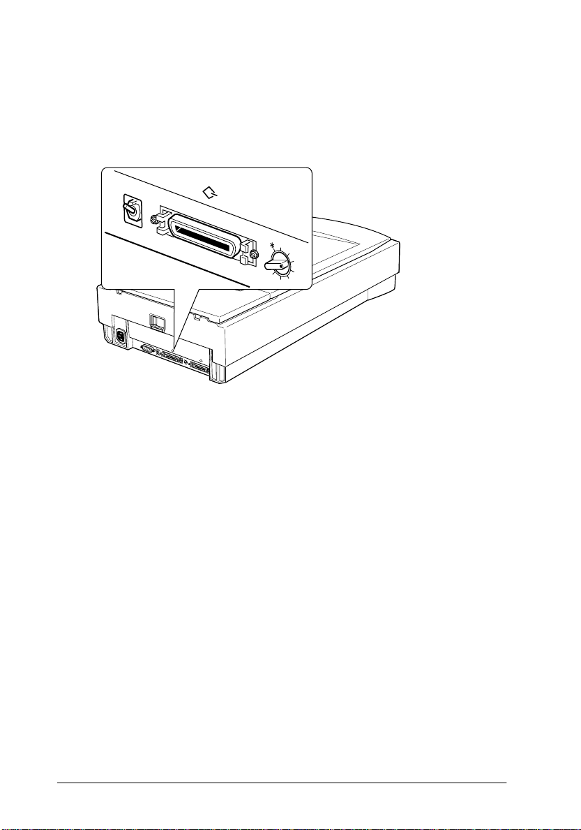
Scanner Parts
carriage
(in the home position)
document table
ERROR light
READY light
1
document cover
OPERATE ligh t
RESET button
SCSI terminator sw itch SCSI ID rotary switch
AC inlet SCSI interface connectors
transportation lock lever
UNLOCK LOCK
OPTION
option interface connector
OPERATE button
TERMINATOR
SW
ON
OFF
SCSI
ID
0
1
2
7
3
6
4
5
Setting Up the Scanner
1-3
Page 18

Choosing a Place for the Scanner
Follow the guidelines below when selecting a location for your
scanner:
❏ Place the scanner on a flat, stable surface. The scanner will not
operate properly if it is on an angle.
❏ Place the scanner close enough to the computer for the
interface cable to reach it easily.
❏ Place the scanner near a wall outlet where the power cord can
be easily unplug ge d.
Note for French-speaking users:
Placez le scanner près d’une prise de courant où la fiche peut-être
débranchée facile ment.
❏ Allow space behind the scanner for the cables, and space
above the scanner so t hat you can fully raise the document
cover.
1-4
Setting Up the Scanner
Page 19
550 mm
1
134 mm*
562 mm
332 mm
* When document cov er is closed.
150 mm or more
❏ Keep the scanner away from high temperatures, humidity
and excessive dirt or dust. Also avoid u sing or storing the
scanner in places subject to r apid changes of temperature and
humidity.
❏ Keep the scanner away from direct sunlight and strong light
sources.
❏ Avoid places subject to shocks and vibrations.
Setting Up the Scanner
1-5
Page 20

Installing a SCSI Interface Board (Windows Only)
Unless your PC already has a SCSI board installed, you need to
install one along with SCSI driver software before installing the
scanner driver and software applica ti ons.
If you have a Macint osh, or if you already have a SCSI board
installed in your PC, go to the next section.
Note:
For additional informat ion, see the installation guide t hat comes with
your SC S I bo ar d .
1. Turn off the computer and any peripheral devices. Unplug
any powe r cords, th en disconne ct all cables from the back
panel of your c omputer.
2. Remove the cover from your computer.
Caution:
w
Static electricity can damage electronic components.
Discharge static electricit y by touching the metal frame of
your computer before handling the interface board or any of
the computer’s circuit boards.
3. Insert th e i nter fac e boar d in t o an appropriate expansion slot,
then secure it with the retaining screw.
4. Replace the computer cover and reconnect all cables.
1-6
Setting Up the Scanner
Page 21
Releasing the Transportation Lock
You must release the transporta tion lock befo re connecti ng the
scanne r to a power source.
1. Place the scanner on a flat, stable surface with its rear panel
facing you.
2. Slide the transportat ion loc k lever on the back of the sc anner
to the UNLOCK posit ion.
UNLOCK
LOCK
UNLOCK
LOCK
OPTION
TERMINATOR
SW
ON
SCSI
OFF
ID
0
1
2
7
6
3
4
5
Note:
Simply sliding the tran sp ort ation l ock t o the
fully lock the carriage. Before moving or transporting the scanner, be
sure to perform the procedure under "Transporting the Scanner and the
Transparency Unit" on page 4-4.
LOCK
position does not
1
Setting Up the Scanner
1-7
Page 22
Plugging in the Scanner
1. Make sure the scanne r is turned off. The sca nner is off when
POPERATE
the
2. If the power cord is not attached to the scanner, connect it to
the AC inlet on the back o f the scanner, and plug the other
end into a properly grounded electrical outlet.
button is raised (not depressed).
RESET
OPERATE
c
1-8
UNLOCK
LOCK
OPTION
TERMINATOR
SW
ON
SCSI
OFF
ID
0
1
2
7
6
3
4
5
Caution:
It is not possible to change the sc ann er's vol ta ge . If the label o n
the back of the scanner does not show the correct voltage for your
country, contact your dealer. Do not plug in the power cord.
Setting Up the Scanner
Page 23
Initialization
By obse r ving how the sc an ne r acts duri ng i n i t i al ization, you can
make sure it i s op e ra ting properly bef o re you connect it to your
computer.
1. Open the document cover so you can see the operation of the
scanner during initialization.
P
OPERATE
2. Turn on the scanner by pressing the
At this time, the carriage moves towards the front of the scann er
slightl y. Next, the fluorescent lamp on the carria ge flash s for about
10 seconds while the carriage moves forward and back. Finally the
carriag e returns to it s original posit ion, and then th e
lamp lights.
READY
button
indicator
1
.
RESET
OPERATE
Setting Up the Scanner
1-9
Page 24

Connecting the Scanner to Your Computer
For PC users:
Unless your PC already has a SCSI board installed, you need to
install one, along with SCSI driver softwar e. Install the SCSI board
according to the directions included with the board. Also see
"Installing a SCSI Interf ace Board (Windows Only)" on page 1-6.
If your PC has a SCSI board up and ru nning, connect t he scanner
as described in the next section.
Note:
You will need to install the SCSI driver that is normally included with
Windows 95, 98, or NT (see yo ur sy stem d ocumentation for
instructions), or the dr iv er d escri bed in the SCSI board installat ion
documentation.
For Macintosh u ser s:
Conventional Macintosh computers have built-in SCSI por ts;
therefore you do not need to in stall a SCSI boar d on a Macintosh .
Follow the directions below to connect your scanner an d
computer.
1-10
Setting Up the Scanner
Page 25
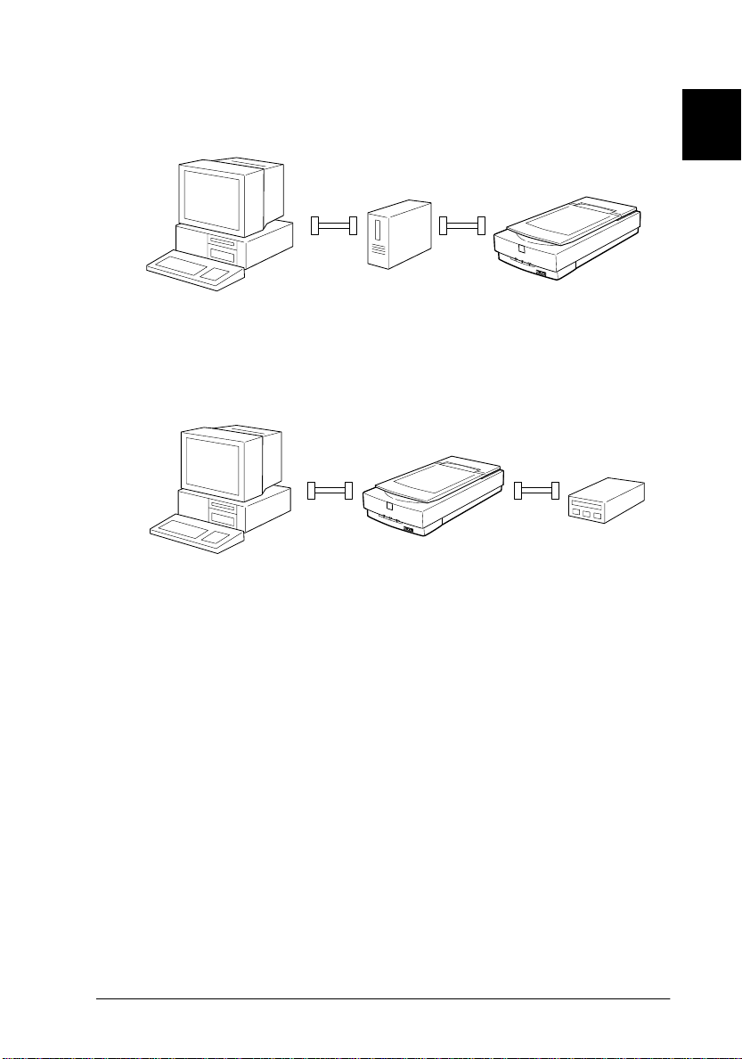
Understanding SCSI connections
Read the following sections to determine how to set up your SCSI
devices and whether you need any optional SCSI cables.
Daisy chain
The SCSI interface allows you to connect up to seven devices (such
as a scanner, hard disk, CD-ROM, and so on) to the computer, in what
is called a “daisy chain” arr angement. Only the first SCSI device in
a daisy chain is connected to the c omputer; eac h of the o ther devi ces
is connected to another SCSI device.
SCSI cables
You may need to purchase SCSI cab les be fore set ting u p y our SCSI
daisy chain. Be sure the SCSI cable connectors are suitable for your
hardware, depending on the maker of your SCSI devic e and SCSI
interface board.
1
SCSI ID and t ermi nator
Each device has a SCSI ID number : the computer is usually
number 7, and each of the other devices must have a different
number between 0 and 6. Also, the first device and the last device
in the chain (not including the computer) must have a terminator.
No other device can have a terminator, or if a terminator does
exist, it must be turned off or removed.
Setting Up the Scanner
1-11
Page 26
Setting the SCSI ID number
The scanner's default SCSI ID number is 2.
ON
OFF
7
6
5
UNLOCK
LOCK
OPTION
TERMINATOR
SW
ON
SCSI
OFF
ID
0
1
2
7
6
3
4
5
The SCSI ID rotary switch
is located on the back of
the scanner.
1
2
4
1-12
Setting Up the Scanner
Page 27

If you add the scanner to a system in which one of your SCSI
devices already has a SCSI ID of 2, change the scanner ID n umber
to an unused number using the rotary switch. See the table below
as a guide.
ID Availability Description
0 Not available for Macintosh Used for hard disk
1
Not recommended for
Windows
1 Not recommended Us ually used for hard disk
2 Factory setting of the scanner
3 Not available if your Macintosh
4
5
6
7 Not available for Macintosh Always used for the Macintosh
May not be available for
Windows
Not available Never selected
✽
* Scanner will not work if selected.
Usually used for hard disk
has a built-in CD-ROM
itself
Usually used for the SCSI board
*
Use only to prepare the scanner
for transportation. See
"Transporti ng the Scanner and the
Transparency Unit" on page 4-4.
c
Caution:
Do not set the SCSI ID to an ID number that is already assigned
to another device otherwise the computer, scanner, and other
devices will not operate properly .
Setting Up the Scanner
1-13
Page 28
Setting the terminator switch
The scanner has a built-in ter minator, which allows SCSI devices
to communicate properly with each other. You may need to
change the terminator switch setting according to your computer
system.
Note:
Do not use an external terminator.
ON
OFF
1
2
7
6
4
5
UNLOCK
LOCK
OPTION
TERMINATOR
SW
ON
SCSI
OFF
ID
0
1
2
7
6
3
4
5
Only the scanner is connected
The termin ator s witch is located
on the back of the scanner.
1-14
terminator on
Setting Up the Scanner
Page 29
The scanner is the last device in the daisy chain
T
(other SCSI device)
he scanner is in the middle of the daisy chain
terminator off
1
terminator on
(other SCSI device )
Connecting the scanner
Connect the scanner to you r compute r or t o anoth er SCSI devic e
as follows:
Note:
The combination of 50-pin and 25-pin connectors you need vari es
depending on the ma ker of your SCSI device and SCSI interface board.
1. Make sure the scanner, computer , and all o ther SCSI dev ice s
are turned off and unplugged from the power source.
Caution:
c
Do not connect the scanner to the computer or other devices
while they are turned on as damage may occur.
Setting Up the Scanner
1-15
Page 30
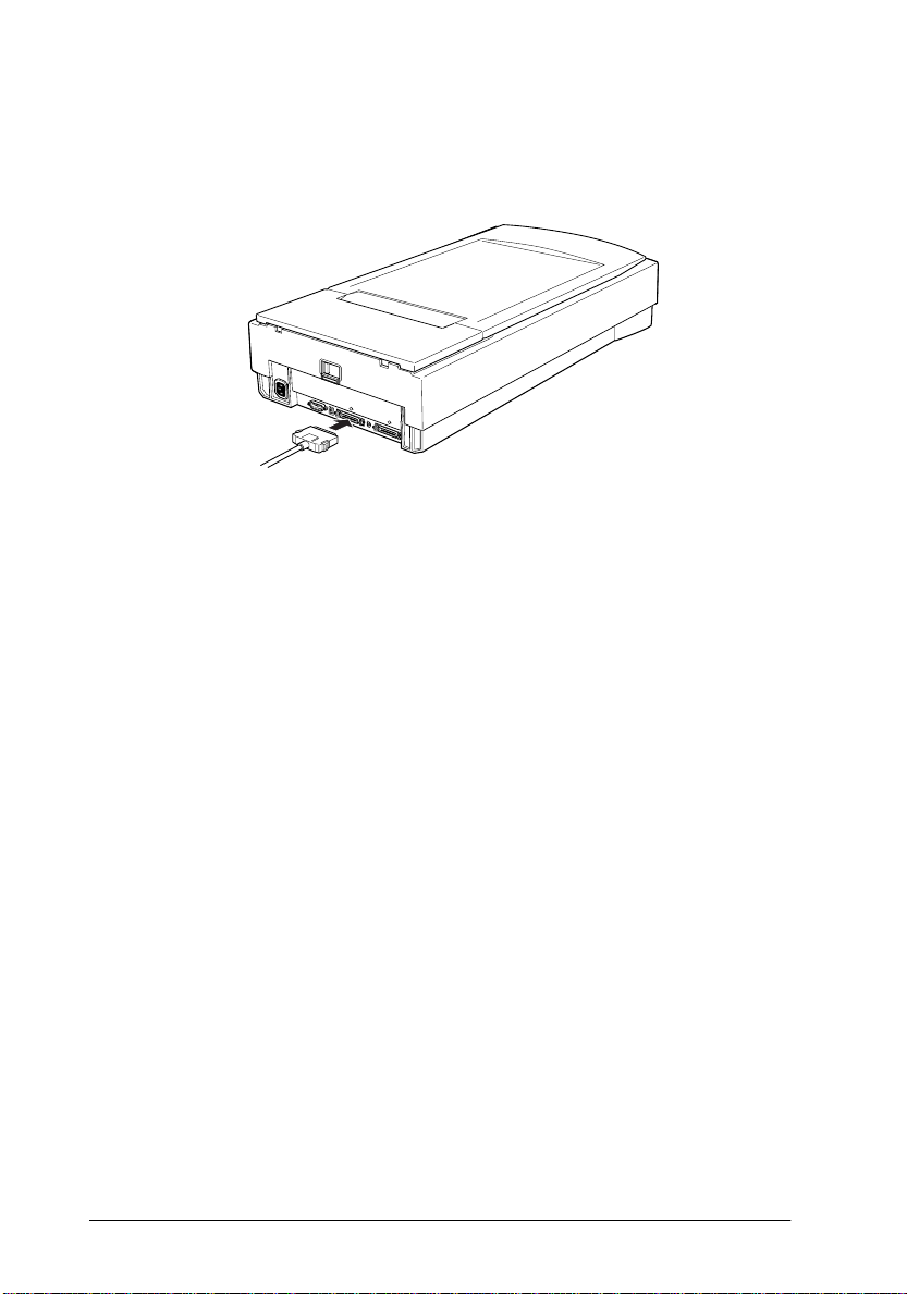
2. Insert one end of the interface cable into one of the scanner
SCSI connectors and press until the locks on both sides snap
in.
UNLOCK
LOCK
OPTION
TERMINATOR
SW
ON
SCSI
OFF
ID
0
1
2
7
6
3
4
5
Note:
❏
To connect the scanner to a SCSI device oth er than the
computer, the length of cable in the daisy chain must not exceed
6 meters; otherwise the system may not work properly.
❏
To connect the scanner to a PC using SCSI-2, the length of the
cable must not exceed 3 meters.
3. Connect the other end of the cable to the SCSI port of your
computer or another SCSI device.
Note:
The SCSI port on the Macintosh is the larger port w ith the SCSI
icon over it.
4. Plug in the p ower cords of your computer, scanne r, and other
external SCSI devices.
Note:
Before turning on your system, be sure to read “Power-on sequence”
following.
1-16
Setting Up the Scanner
Page 31

Power-on sequence
Keep the following in mind every time you turn on your computer
and SCSI devices, including the scanner.
❏ Be sure to turn on the SCSI device which is connected at the
farthest end of the daisy chain first, then the second farthest
and so on, until fin ally your computer. If you attempt to use
a SCSI device which has been turned on after the computer,
it may not work prope rly, or the computer may not work
properly.
❏ For Windows 95 or 98 users:
The first time you turn on the computer after turning on the
scanner, one of the following dialog boxes may appear.
Windows 95
1
Windows 98
If you see one of these, follow the installation instructions in
Chapter 1 of your scanner software manual, then s ee “Poweroff sequence”, below.
Setting Up the Scanner
1-17
Page 32

Power-off sequence
Keep the fo llowing in mi nd every time you turn off your
computer and SCSI devices.
❏ When you are finished using your system, turn off your
computer first, then the sc anner and other SCSI devices i n
reverse or der of the power-on sequence.
❏ While using you r computer, do not turn off any SCSI device
which has a terminator that is active (on).
❏ Do not turn the scanner o ff and back on while using your
computer, otherwise the scanner may not work properly.
When the connection is complete, you need to install the scanner
software. See Chapter 1 of your scanner software m anual.
1-18
Setting Up the Scanner
Page 33

Chapter 2
Using Your S c a nn er
Lights and Buttons . . . . . . . . . . . . . . . . . . . . . . . . . . . . . . . . . . . . . . . 2-2
Placing a Document on th e Scanner . . . . . . . . . . . . . . . . . . . . . . . . .2-4
Removing the Cover for Thick or Large Document s . . . . . . . . . . . 2-7
Sizing Up Your System. . . . . . . . . . . . . . . . . . . . . . . . . . . . . . . . . . . .2-9
RAM and hard disk size . . . . . . . . . . . . . . . . . . . . . . . . . . . . . . 2-9
Accelerator boards . . . . . . . . . . . . . . . . . . . . . . . . . . . . . . . . . . . 2-9
Video cards . . . . . . . . . . . . . . . . . . . . . . . . . . . . . . . . . . . . . . . . . 2-9
Monitors. . . . . . . . . . . . . . . . . . . . . . . . . . . . . . . . . . . . . . . . . . . . 2 -10
File compression software. . . . . . . . . . . . . . . . . . . . . . . . . . . . . 2-10
2
Using Your Scanner
2-1
Page 34
This chapter shows you how the scanner operates. The basic
procedure for scan ning is as f ollows:
1. Turn on the s canner. ( Keep in mi nd the "Power-on seq uence"
on page 1-17.)
2. Place the document you want to scan on the document table.
(This is described in detail on page 2-4.)
3. Run the scanner software and scan. (See your scanner
software manual for details on scanning.)
Lights and Buttons
The scanner has three indicat or lights and two buttons.
2-2
Using Your Scanner
RESET
OPERATE
Page 35

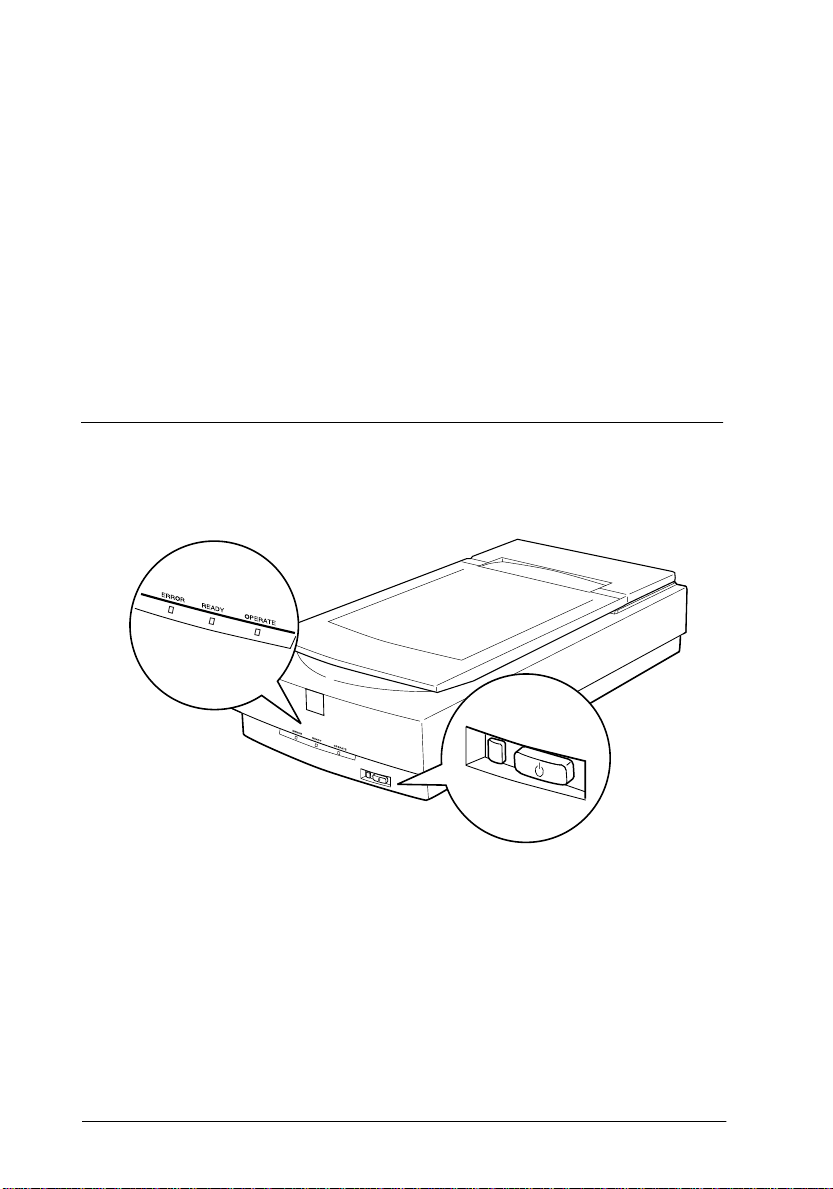
Lights
Lights Color Indicator
OPERATE
READY
ERROR
Green Lit Scanner is turned on.
Green
Red
Buttons
Button Function
OPERATE Turns the scanner on and off.
P
RESET Resets the scanner after an error. Pressing this
]
Status
Lit Scanner is ready to scan.
Flashing Scanning operation is in
Lit This indicator also lights when
Flashing
button while scanning is in progress stops the
scanner and may cause an error in the
scanning software.
Meaning
progress.
Error. See "Er ror indicator" on
page 4-5 for more information
about errors.
an error occurs.
Error. See "Er ror indicator" on
page 4-5 for more information
about errors.
2
Using Your Scanner
2-3
Page 36

Placing a Document on the Scanner
Before sca nning a document, remember to re spect the rights of
copyr ig ht ow ner s. D o no t sca n pu bli she d te xt o r ima ges with ou t
first checking the copyright stat us.
1. Turn on the scanner by pressing the
OPERATE
light come s on.
OPERATE
P
OPERATE light
button. T he
2. Turn on the comp uter and make sure that the scanner's
READY
light is on. Open the document cover.
2-4
Using Your Scanner
Page 37

3. Place the do cument on the documen t ta ble, with the s i de to
be scanned facing down. Make sure that the document is
carefully aligned.
corner of the document
4. Close the document cover gently so that the document does
not mov e.
2
Using Your Scanner
2-5
Page 38

Note:
❏
Make sure the document is fla t a g ainst the glass surface,
otherwise the image will appear fuzzy and out of focus. Also be
sure to close the document cover to prevent interference from
external light.
❏
Always keep the document tab le clean. See “Cleaning the
Scanner” in Chapter 4.
❏
Do not leave photographs on the document table for an extended
period of time as they may stick to t he glass.
❏
Do not place heavy objects on top o f the scan ner.
5. Start your scanner software, and follow scanning instr uctions
in your scanner software manual.
2-6
Using Your Scanner
Page 39

Removing the Cover f or Thick or Large Documents
Carefully lift straight up on the back of the document cover.
Hold the back of the document
cover and lift straight up.
Note:
When scanning with the cover removed, do not leave any area of the
document table exposed to p reven t in terf erenc e from ex ternal light.
2
Using Your Scanner
2-7
Page 40

When y ou ar e f ini she d s cann ing , reat t ach th e d ocume nt c over by
pushing straight down on the back until it clicks into place.
Caution:
c
Make sure both of the notches in the cover's hinges are directly
above the clips
place. Improperly aligned notches can damage the cover.
on the scanner before pushing the cover down into
2-8
Using Your Scanner
Page 41

Sizing Up Your System
Your scan ner is suff ic ient fo r mos t scan ning needs , but if you a re
not satisified with the quality of the images on your monitor or
with the speed of image processing, read this section. While it
does not contain specific recommendations, it describes various
possibilities for improving your scanning system. For further
information, seek advice from your dealer or an experienced
scanner us er.
RAM and hard disk size
Scanned images use much more memory than tex t fi les, so
you may ne e d more RAM (Ran dom Access Mem ory) in your
computer and a larger hard disk than you have used previously.
Accelerator boards
In addition to memory, processing speed is importan t because
large files take longer to process than small ones. Therefore, y ou
may want to add an accelerator boa rd to your co mputer.
2
Video cards
A video card that is sufficient for text may not be good enough
for displaying graphic images, especially in color. If all your
scanned images look coarse on your monitor, you may want to
upgrade your video card. You will need 24-bit c olor, also called
true color or mi llions of colors, to make the highest q uality im age
reproductions.
Using Your Scanner
2-9
Page 42

Monitors
The resolution of your monitor affects t he quality of the image
you see. Consider a high resolution monitor if you do precise color
work, but also be sure you have a high quality video ca rd.
File compression software
Many different programs are available to make image files
smaller for storage or transmission. For example, some
compression software c an store a 3MB image file on a 1.44MB
floppy disk, an d co mpress i mages and r es tore t h em with no los s
of data or quality; others compress images more , but the restored
file is not exactly the same as the original. The difference between
the original and restored files is, however, almost unnoticeable.
2-10
Using Your Scanner
Page 43

Chapter 3
Options
Using the Transparency Unit. . . . . . . . . . . . . . . . . . . . . . . . . . . . . . .3-2
Unpacking the Transpa rency Unit. . . . . . . . . . . . . . . . . . . . . . 3-2
Removing the shipping screw . . . . . . . . . . . . . . . . . . . . . . . . . 3-3
Installing the Transparency Unit . . . . . . . . . . . . . . . . . . . . . . . 3-4
Transparency guide and reflective d o cument mat . . . . . . . . 3-6
Positioning transparencies for scann ing . . . . . . . . . . . . . . . . . 3-7
Scanning normal (reflective) documents . . . . . . . . . . . . . . . .3-10
Using the Automatic Document Feeder. . . . . . . . . . . . . . . . . . . . . . 3-12
Unpacking the Autom a tic Do cum e nt Feeder. . . . . . . . . . . . . 3-12
Installing the Automatic Document Feeder . . . . . . . . . . . . . .3-13
Loading paper into your Au tomatic Document Feeder . . . . 3-15
Loading documents manually . . . . . . . . . . . . . . . . . . . . . . . . .3-17
Document specifications . . . . . . . . . . . . . . . . . . . . . . . . . . . . . .3-17
3
Opti o ns
3-1
Page 44

Using the Transparency Unit
The optional Transparency Unit (B81315✽) makes it possible to
scan transparencies and slides, in full color. Once you install the
Transparency Unit, you can leave it in place even when you want
to return to scanning normal (paper) documents.
Unpacking the Transparency Unit
Make sure that all th e items sh own bel ow are inclu ded and have
not been damag ed duri ng shipp ing. Con tact your EP SON deal er
if any item is missing or damaged.
installati on
screws ( 2)
Transpare ncy Unit
document mat
film holderreflective
transparency guides
Note:
Do not store the small transparency guide in the po cket.
3-2
Options
Page 45

Removing the shipping screw
A shipping screw is installed on the Transparency Unit to prevent
damage during shipping. Be sure to use the following procedure
to remov e this screw befo re attempting to use the unit.
1. Turn over the Tr ansparency Unit so its glass side is facin g up.
2. Remove the shipping screw as shown below.
3. Screw the shipping screw into the storage hole as show n.
3
Opti o ns
3-3
Page 46

Note:
Before transporting the scanner, rem ove the Transparency Unit and
return the shipping screw to its original shipping hole. See
"Transporti ng the Scanner an d the Transpar ency Unit" on page 4- 4 for
details.
Installing the Transparency Unit
Follow the steps below to install the Transparency Unit on the
scanner.
1. Make sure the scanne r i s turned off, and unplug the power
cord.
2. Remove the document cover from the scanner by lifting
straight up on its back edge. (See page 2-7)
3. Slide the mounting slots on the Transparency Unit under the
two insta llation sc re ws attache d to the sc anner.
3-4
Options
Page 47

4. Insert the two insta llation scre ws provided with the
Transparency Unit into the holes as shown below, and then
tighten t he screws wit h a coin.
5. Close the Transparency Unit.
6. Connect the Transparency Unit's connector to the option
connector on the scanner.
3
OPTION
UNLOCK
LOCK
OPTION
TERMINATOR
SW
ON
SCSI
OFF
ID
0
1
2
7
6
3
4
5
Opti o ns
3-5
Page 48

Transparency guide and reflective document mat
Three transparency guides and a film holder for scanning
transpar encies and a reflective do cument mat f or scanning
normal paper documents are included with this unit. To use them,
see the instructions below.
small
transparency
guide
Caution:
c
Do not put the small transparency guide into the Transparency
Unit pocket.
transparency guides
film holder
Reflective
document
mat
3-6
Options
Page 49

Positioning transparencies for scanning
Note:
❏
Be sure to wipe the Transparenc y U nit glass, the scanner’s
document table, and the narrow window near the mounting bracket
with a soft cloth before scanning transparencies.
❏
Operation of the Transparency Unit is controlled automatically by
your scanner software.
1. Open the Transparency Unit.
2. Place the transparency guide onto the scanner’s do c um ent
table.
See the following pages for details on each of the following
types of transparenci es.
35mm film strips ... page 3-8
Mounted slides ... page 3-8
120/220 film ... page 3-9
4 x 5 inch film ... page 3-9
3
Non-standard film sizes ... page 3-1 0
3. Place the t ransparency on the s canner’s glass document table,
aligning it with the upper ri ght-hand c o rner of the
transparency guide. Make sure the glossy side of the
transparency is facing down.
4. Close the Transparency Unit. If the reflective document mat
is installed on the Transparency Unit, remove it.
Note:
Make sure the Transparency Unit is completely closed. Otherwise an
option error will occu r and sc anning will be impossible.
Use your s ca nner softwa re to scan the transparency.
Opti o ns
3-7
Page 50

35mm film strips
Slide the film strips into the film holder, making sure the glossy
(smooth) side of the film is facing up. When placing the
transparency guide with film strips o nto the scann e r’s glass
document table, the glossy side of the film should be facing down.
Mounted slides
Place the slides in side the sli de transpare ncy guide , making sure
the glossy (smooth) side of the film is facing down.
3-8
Options
Page 51

120/220 film
Place the film into the sl ide tr anspare ncy guide, making sure the
glossy (smooth) side of the film is facing do wn. Make sure that
the area you want t o scan is ali gned prop erly with the opening in
the transpa rency guide .
4 x 5 inch film
Place the film into the sl ide tr anspare ncy guide, making sure the
gloss y (smoot h) side of the f ilm is f acing down. The area yo u want
to scan should be aligned properly with the opening in the
transparency guide.
3
Opti o ns
3-9
Page 52

Non-standard film size s
Place the fi lm directly onto the sca nner’s glass d ocument ta ble,
making sure the glossy (smooth) side of the film is facing down.
Scanning normal (reflective) documents
When you return to scanning normal refle ctive documents, y ou
should always insert the reflective document mat included with
this unit. Also, make sure yo u re move the tran sparency guide
from the scanner's documen t table.
Insert the reflective document mat as descri bed below.
1. Open the Transparency Unit.
3-10
Options
Page 53

2. Insert the tabs on the reflective paper document mat into the
slots on the Transparency Unit and slide the mat into place.
3. Positi on the reflect iv e document and close the unit.
3
Options
3-11
Page 54

To remove the reflective document mat, slide it up and out of the
slots on the Transparency Unit.
Using the Automatic Document Feeder
The Automatic Document Feeder (B81316✽) allows you to
automatically load multiple-page documents into the GT-9600
scanner. This document feeder is particularly useful for OCR
(optical charact er recognition ) scanning, or for creat ing an image
database.
Unpacking the Automatic Document Feeder
When you unpack your Automatic Document Feeder, make sure
you have all the parts shown below and that none is damaged. If
you find any missing or damaged items, co ntact your EPS O N
dealer immediately.
3-12
Installat ion
screws
Aut omatic Document Feeder
Options
Page 55

Installing the Automatic Document Feeder
Follow the steps below to install the Automatic Document Feeder
on your EPSON scann er.
1. Make sure your scanner is turne d off, and unplug the
scanner's power cord.
2. Remove your scanner's document cover by holding the cover
behind the hinge and lifting the back of the cover straight up.
(See page 2-7)
3. The scanner comes with two installation screws attached;
slide the mounting slots on t h e Automatic Document Feeder
forward, underneath the se two scre ws. Do not remove the
protective materials from the Automatic Document Feeder's
mounting hardware yet.
3
Options
3-13
Page 56

4. Insert the installation screws included w i th your Automatic
Document Feeder into the holes in the scanner, then use a coin
to tighten them.
5. Remo ve the protecti ve materials from the Automatic
Document Feeder's mounting ha rdware.
6. Close the Automatic Document Feeder.
7. Attach the Automatic Document Feeder's connect e r to the
scanner's option inter face.
OPTION
UNLOCK
LOCK
OPTION
TERMINATOR
SW
ON
SCSI
OFF
ID
0
1
2
7
6
3
4
5
3-14
Options
Page 57

Loading paper into your Automatic Document Feeder
Your Auto matic Document Feeder can auto matically load up to
30 sheets of the following paper sizes (based on a paper weight of
17 lbs and a stack thickness of 6.0 mm or less):
Checks 76 x 127 mm (3 x 5 inches)
B5 182 x 257 mm (7.17 x 10.1 inches)
A4 210 x 297 mm (8.27 x 11.69 inches)
Letter 215.9 x 279.4 mm (8.5 x 11 inches)
Legal 215.9 x 355.6 mm (8.5 x 14 inches)
Follow the steps below to load paper into the Automatic
Document Feeder.
1. Slide the left edge guide all t he way to the left and place your
paper in the feeder tray. Then move the right edge guide so
it is flush wi th the right ed ge o f your paper.
3
Options
3-15
Page 58

Note:
For checks, move the left ed g e g uid e to the c enter till it stops, then
place your check s i n the tra y and mo ve the ri ght e dge flu sh a gain st
them.
2. Insert th e paper stack into the Automatic Document Feeder
until it meets resistance. Make sure that the side you want to
scan is facing up.
Documents are fed into the lower tray after scanning is finished.
3-16
Options
Page 59

Loading documents manually
You can load documents manually even when the Automatic
Document Feeder is installed.
To load manually, lift the Automatic Document Feeder and place
the document on the scanning surface. Then lower the Automatic
Document Feeder and scan the document.
Note:
❏
Opening the Auto m at ic D oc um ent Feeder or its cover while it is
operating results in an opt ion error an d pap er feeding stops.
❏
Always close the Automatic Documen t Feeder and its cover before
using it.
Document specifications
Size: Width 3 to 8.5 inches (76 to 215.9 mm)
Length 5 to 14 inches (127 to 355.6 m m)
Thickness: 0.07 to 0.16 mm
Weight: 52.3 to 127.9 g/m
2
3
Paper qu ality: High-quality bond or thermal pa pe r
Document type: Documents printed with impact
printers, laser printers, or facsimile
machines
Document conditions
Make sure of the following before feeding a document:
❏ Ink on the document is dry.
❏ The document has no holes, is not ri pped or wrinkled, and
has no articles attac he d to it.
Options
3-17
Page 60

❏ The document has no staples or other objects attached th at
might damage the feeder mechanism.
❏ The document has no folds closer than 8 mm from its edge.
❏ The document is not a multipart form or bound.
❏ The document has no rear carbon coating.
❏ The document has no cut out areas.
Other precautions
Do not feed photographic sheets or particularly valu able original
artwork into this Automatic Document Feeder; misfeeding a
document may result in accidental wrinkling or damage.
When yo u are scann ing high-q uality co lor or half tone doc uments,
it is recommended you open the Automatic Document Feeder and
scan documents individu ally.
3-18
Options
Page 61

Chapter 4
Maintena nce and Troub leshooting
Maintenance . . . . . . . . . . . . . . . . . . . . . . . . . . . . . . . . . . . . . . . . . . . . . 4-2
Cleaning the scanner . . . . . . . . . . . . . . . . . . . . . . . . . . . . . . . . .4-2
Replacing the fluorescent lamp . . . . . . . . . . . . . . . . . . . . . . . .4-3
Transporting the Scanner and the Transparency Unit. . . . . . . . . . 4-4
Problems and Solutions . . . . . . . . . . . . . . . . . . . . . . . . . . . . . . . . . . . 4-5
Error indicator. . . . . . . . . . . . . . . . . . . . . . . . . . . . . . . . . . . . . . . 4-5
Operating problems . . . . . . . . . . . . . . . . . . . . . . . . . . . . . . . . . .4-7
Quality problems . . . . . . . . . . . . . . . . . . . . . . . . . . . . . . . . . . . . 4-9
Paper jams . . . . . . . . . . . . . . . . . . . . . . . . . . . . . . . . . . . . . . . . . . 4-16
Viewing the Color Guide . . . . . . . . . . . . . . . . . . . . . . . . . . . . . . . . . .4-17
Changing the SCSI ID Number or SCSI Board . . . . . . . . . . . . . . . . 4-18
4
Maintenance and Troubl eshooting
4-1
Page 62

Maintenance
Cleaning the scanner
To keep your scanner operating at its best, you should clean it
periodically, as described below.
1. Unplug the power cord.
2. Clean the outer case with mild detergent and wate r.
3. If the doc ument ta bl e gla ss b ec omes dir ty, cl ean i t wi th a sof t
dry cloth. If th e glass is stained with grease or some other
hard-to-remove mater ial, use a small amount of glass cleaner
and a soft cloth to remove it. Wipe off all remaining liquid.
Be sure that there is no dust on the document table glass. Dust can
cause white spots in your scanned image.
Caution:
w
❏ Be careful not to scratch or damage the document table glass,
and do not use a hard or abras ive brush to clean it. A damaged
glass surface can decrease scanning quality.
4-2
❏ Never use alcohol, thinner, or corrosive solvent to clean the
scanner. These chemicals can damage the scanner
components as well as the case.
❏ Be careful not to spill liquid into the scanner mechanism or
electronic components. This could permanently damage the
mechanism and circuitry.
❏ Do not spray lubricants inside t h e scanner.
❏ Never open the scanner case.
Maintenance and Troubleshooting
Page 63

Replacing the fluorescent lamp
The luminosity of the fluorescent lamp declines over time. If the
lamp breaks or becomes too dim to oper ate normally, the scanner
stops working and the
this happens, the lamp assembly must be replaced. For details,
contact your dealer.
Caution:
c
Never open the scanner case. If you think repairs or adjustments
are necessary, consult your dealer.
OPERATE
light rapidly flashes red. When
4
Maintenance and Troubl eshooting
4-3
Page 64

Transporti ng the Scanner and the Transpare ncy Unit
When transporting the scanner or the Transparency Unit over a
long distance, or storing them for an extended period, you need
to lock the scanner’s carriage and the Transparency Unit’s lamp
assembly, to prevent damage. Follow the procedures below.
For the scanner
1. Make s ure the tran sportation lock lever is in the
UNLOCK
position.
2. Align the SCSI ID rotary switch with "✽".
3. Turn on the scanner.
4. After the carriage moves to the back of the scanner, slide the
transportation lock lever to its
UNLOCK
LOCK
UNLOCK
LOCK
OPTION
TERMINATOR
SW
ON
SCSI
OFF
ID
0
1
2
7
6
3
4
5
LOCK
position.
For the optional Transpar ency Unit
1. With the Transparency Unit attached, turn on the scanner and
wait until the unit’s lamp assembly moves to its home
position. Then turn off the scanner and re move the
Transparency Unit.
4-4
Maintenance and Troubleshooting
Page 65

2. Raise the front of the Transpar ency Unit, hold it upright, an d
gently shake it up and down once so that the lamp asse mbly
slides down toward the back of the unit. Wait until the lamp
assembly comes to rest.
3. Install the shipping screw in its original shipping hole.
Problems and Solutions
This section divides scanner problems into three categories:
Error indicator. . . . . . . . . . . . . . . . . . . . . . . page 4-5
Operating problems . . . . . . . . . . . . . . . . . . page 4-7
Quality problems . . . . . . . . . . . . . . . . . . . . page 4-9
See the ta bl e in “Error indic ator” first. If thi s does not help you
solve your problem, go to the category for the type of problem
you have , the n look for the problem des cri ption.
The online Color Guide also provides versatile tips and other
information helpful for problem-solving.
Error indicator
When an error occurs, th e scanner stops operating an d the
READY
and
ERROR Light READY Light Error Type
On On Command error
Flashing Off Interface error
Flashing Flashing Fatal error
lights indic ate the error type as described below.
ERROR
4
Off Off Option error
Maintenance and Troubl eshooting
4-5
Page 66

Command error
The scanner has rece ived incorrect commands fro m your
scanning software.
When this error occurs, try to rescan the document. The scanner
returns to normal when it receives correct commands. Normally
you do not need to reset the scann e r when this t y pe of error
occurs.
Interface error
The interface setup is wrong or the scanner is n ot properly
conne cted to the print e r .
When this error occurs, check the interface connection and then
push the
again to reset it.
RESET
button or turn the scanner off and then back on
Fatal error
This type of error indicates one of the following problems:
❏ The fluorescent lamp needs to be replaced.
❏ The transportation l ock lever is not release d.
❏ The scanner is malfunctioning.
Check that the tr ansportation lock lev er is released and check any
installed options for problems. Next, turn the scanner off and then
back on again. If this does not correct the problem, consult your
dealer.
Option error
This indicates a p roblem with an ins talled optio n such as a paper
jam, an empty document feeder, or an open cover.
Check the option and correct the cause of the problem.
4-6
Maintenance and Troubleshooting
Page 67

Operating problems
Problems you may have while using the scanner often involve the
operation of your software and computer. Operation problems
usually occur be cause of:
❏ Incorrect setup of the interface (see Ch apter 1).
❏ Inappropriate selection of the scanner functions (s ee your
software manual).
❏ Incorrect se tup of your computer or s oftware (see Chapter 1
in this guide or the software manual).
❏ Incorrect operation of your software (see your software
manual).
Also see the documentation that came with your computer and
printer for possible so lutions.
The OPERATE light does not light.
Cause What to do
P
OPERATE
Scanner is of f Press the
on the scanner.
Scanner is not connected
correctly
Make sure the power cord is
connected to the scanner and plugged
into a power outlet.
button to turn
The scanner does not scan.
Cause What to do
4
The scanne r is not rea dy to
scan
Wait until the
(ready for scanning).
Maintenance and Troubl eshooting
READY
light is green
4-7
Page 68

Interface or software setting
problem
SCSI problem Make sure the scanner’s S CSI ID and
Interrupt conflict If you have other expansion boards in
Make sure your interface port and
softwa re se t t i n gs are co rrrect. Al so
make sure that your computer’s
interface board is installed properly.
terminator are set correctly.
your computer, make sure that their
interrupt sett ings are not interfering
with your SCSI board. See your
computer’s documentation for
details.
The scanner software does not work properly.
Cause What to do
Software installation
problem
Computer system
requirement problem
4-8
Maintenance and Troubleshooting
Make sure your software is installed
correctly.
Make sure your computer meets the
memory an d ot he r system
requirements specified for the
software you are using.
Page 69

Quality problems
The entire image is d isto r ted or blurred.
Cause What to do
Document placement Make sure the document is flat against
the documen t ta b le .
Documen t movement Make sure you do not accidentally
move the document during scanning.
Scanner orientation Make sure the scanner is on a flat,
stable surface.
Part of the image is distorted or blurred.
Cause What to do
4
Document condition or
placement
Make sure the document is unifromly
flat against the document table. A
docume nt tha t is wrink led or war ped
can caus e pr ob l em s .
Edges of the document are not scanned.
Cause What to do
Document size If your doc ument is too large , position
it so the area you w ant to scan is w ithin
the lim it marks on the edg e guides of
the documen t ta b le .
Maintenance and Troubl eshooting
4-9
Page 70

Colors are patchy or distorted at the edges of the image.
Cause What to do
Document condition A document that is very thick or
warped at the edges can cause
discoloration. Cover the edges of the
documen t with paper to bloc k outside
light.
Document placement M ake sure the document is flat agai nst
the document table.
The image is faint or out of focus.
Cause What to do
Document placement M ake sure the document is flat agai nst
the document table.
Gamma set ting Check your software’s Gamma
setting.
Exposure setting Check your software’s Exposure
setting.
The image is too dark.
Cause What to do
Brightness setting Check your software’s Brightness
setting.
Check the brightness and con trast
setti ngs of your computer display.
4-10
Maintenance and Troubleshooting
Page 71

Straight lines in the image come out jagg e d.
Cause What to do
Document placement Make sure the document is oriented
perfectly straight on the document
table. Align vertical and horizontal
lines with the scales at the top and side
of the doc u me nt table .
The image does not look the same as the original.
Cause What to do
Image setti ngs T ry di f f e rent image setting
combinations on your scanner
software.
Color mat ching and co lo r
managment prob lem
File format problem If you are importing an image file,
Your softwar e may not have suffi cient
color mat ching and co lo r
management features, or these
components may not be installed
correctly. See the documentation that
came with y our software and
computer.
make sure the file format is one your
software can read. Also, make sure the
image setti ngs of your software are
appropriate for t he type of i mage you
want to scan.
4
Maintenance and Troubl eshooting
4-11
Page 72

A line of do ts is always missing from the scanned im age.
Cause What to do
Print head malfunction Print head malfunction is indicated
when a line is missing on printouts
only. See your printer manual.
Scanner sensor malfunction Scanner sensor malfunction is
indicated when the line is missing on
both screen images an d printouts.
Contact your dea ler .
A line appears in the scanned image when using the Automatic
Document Feeder.
Cause What to do
The narrow window near the
mounting bracket is dirty
Wipe and remove any dirt on the
window with a soft cloth.
When using halftoning, textured patterns of dots appear
inside particular areas of the image.
Cause What to do
Normal scanning T his condition is normal. The scanner
automa tically mimimi zes the problem
if on is selected for the De-screening
setting in the Image Type dialog box.
4-12
Maintenance and Troubleshooting
Page 73

Colors in the image look odd.
Cause What to do
Image Type and Destination
settings
Operation problem when
using Transparency Unit
Make sure the EPSON TWAIN Pro
Image Type and Destination settings
are correct.
When using the Transparency Unit,
make sure the narrow win dow near
the hinges on the document table is
covere d, or ma ke sure the
Transparency Unit is closed when
scanning.
Colors on your moni tor are different f rom those in t he original
image.
Cause What to do
Software image setting
problem
Color mat ching and co lo r
management capabilities
Check the image settings of your
scann er software, es p ecially data
format (bits, pixel, color), gamma
correct i o n, a nd color corr e ct io n . Tr y
different comb in a ti on s of the s e
setti n g s.
Check the co l o r ma t ching and co lor
management capabilit ies of your
computer, display adapter, and
software. Some computers can change
the color pa lette to adjust the colors on
your screen. See your software and
hardware manuals for details.
4
Normal color matching Exact color matching is very difficult.
Check your software and monitor
manuals for informat io n on color
matching and calibration.
Maintenance and Troubl eshooting
4-13
Page 74

Printed colors are different fro m those in the original image.
Cause What to do
Normal color matching Exact color matching is very difficult.
Check your software or contact your
printer company for information on
color matching and calibration.
The printed im age is larger or smaller than the original.
Cause What to do
Software image size settings The image size settings of your
software det ermine the size of th e
printed image. Do not use the size of
the monitor image to judge the
printed size.
Scanned images ca nnot be printed or come out garbled when
printed.
Cause What to do
Printer connection or setup Make sure your printer is properly
connected to the computer and
correctly set up. See your printer
manual for details.
Software installation
problem
4-14
Maintenance and Troubleshooting
Check that your software is properly
installed and set up for your printer.
See your software manual.
Page 75

The colors of neg a tive f ilm preview images look strange.
Cause What to do
Document Sou rce setting Make sure the EPSON TWAIN P ro
Document Source setting is TPU-Neg.
Film.
Film holder or transparency
guide frame
The dark area around t he film, such as
the frame of the film holder or
transparency guide, is perceived as
white, which alters t he exposure of the
scann ing area and caus e s scans to
appear darker. See t he correct color by
clicking and dragging the mouse over
an area, and then clickin g the
preview
button.
zoom
4
Maintenance and Troubl eshooting
4-15
Page 76

Paper jams
If a paper jam occurs, first open the Automatic Document Feeder's
cover. Then pull forward on the jam-release lever and slowly pull
the jammed paper out of the feeder mechanism. (Be careful not to
pull too hard; the paper m ay tear, making it more diff icult to
remove.)
After removing the jammed paper, close the document feeder
cover and reset the scanner.
4-16
Maintenance and Troubleshooting
Page 77

Viewing the Color Guide
Using an HTML browser on your computer, you are able to view
the Color Guide. This provides tips for handling color imaging
data, usin g several color imaging products, and o the r general
information about color imaging.
You need one of the following browsers, or an equivalent, to view
the Color Guide:
❏Netscape N avigator 3.0 or later
❏Microsoft Internet Explorer 3.0 or later
If a browser is not inst alled on your computer, you need to obtain
one and install it, or you can install the browser that comes with
your Color Guide CD-R OM. For fur t her details, double-click the
Readme.txt (for Windows) or Read Me First icon (for Macin tosh),
and follow the instructions.
To view the Color Guide, double-click on the following icon:
For Windows: color.htm
For Macintosh: Color Guide
4
Then follow the instructions on the screen.
Maintenance and Troubl eshooting
4-17
Page 78

Changing the SCSI ID Number or SCSI Board
If you are usin g yo ur s canner w it h Win dows 9 8 an d you want to
change the scanner’s SCSI ID number or replace the SCSI board
with a new one, follow the s teps below.
1. Double-click the
Control Panel
2. Select your scanner in the installed devices list, then click
Remove
.
Scanners and Cameras
.
icon in the
4-18
Maintenance and Troubleshooting
Page 79

3. Click OK and close the dialog box.
4. Shut down Windows 98 and turn off your PC and scanner.
5. Change the SCSI ID number, or replace the SCSI board.
6. Turn on your scann er and then your PC.
7. Follow the instruc tions on the screen.
4
Maintenance and Troubl eshooting
4-19
Page 80

4-20
Maintenance and Troubleshooting
Page 81

Appendix A
Technical Specifications
Scanning . . . . . . . . . . . . . . . . . . . . . . . . . . . . . . . . . . . . . . . . . . . . . . . . A- 2
Electrical . . . . . . . . . . . . . . . . . . . . . . . . . . . . . . . . . . . . . . . . . . . . . . . . A-4
Environmental . . . . . . . . . . . . . . . . . . . . . . . . . . . . . . . . . . . . . . . . . . . A-4
Safety Approvals . . . . . . . . . . . . . . . . . . . . . . . . . . . . . . . . . . . . . . . . . A-5
CE Marking . . . . . . . . . . . . . . . . . . . . . . . . . . . . . . . . . . . . . . . . . . . . . A- 5
SCSI Interface. . . . . . . . . . . . . . . . . . . . . . . . . . . . . . . . . . . . . . . . . . . . A-6
Initialization Methods. . . . . . . . . . . . . . . . . . . . . . . . . . . . . . . . . . . . .A-7
A
Technical Specificatio ns
A-1
Page 82

Scanning
Scanner type: Flatbed, color
Photoelectric device: Color CCD line sensor
Effective pixels: 6800 × 9360 pixels at 800 dpi, 100%
Document size: 216 mm × 297 mm (8.5 inches × 11.7 inches
A4 or US letter size
(The reading area can be specified from your
software.)
Scanning resol ut i on: 800 dpi optical (main scan)
3200 dpi with micro -step (sub-scan)
Output resolution: 50 dpi to 6400 dpi (1 dpi steps)
12,800 dpi (selectable with zoom function)
Color separation: RGB color filters on CCD
Reading sequence:
Monochrome One-pass scanning
Color page sequence Three-pass scanning (R, G, B)
(This sequence is not supported by EPSON
TWAIN Pro.)
Color byte sequence One-pass scanning (R, G, B)
Color line sequence One-pass scanning (R, G, B)
Zoom: 50% to 200% in 1% steps
Image data: 12 bits per pixel per color internal
1 to 12 bits per pixel per colo r external
Brightness: 7 levels
(In EPSON TWAIN Pro, Gamma correction
controls Bright ness.)
Line Art settings: Fixed threshold
Text Enhancement Technology
(enable/disable selectable)
A-2
Technical Specifications
Page 83

Halftoning process: AAS (Auto Area Segmentation)
Enable/disable selectable
3 halftoning modes (A, B, and C) and
4 dither patterns (A, B, C, and D) for
bi-level and quad-level data
(2 downloadable dither patterns)
Gamma correction: 2 types for CRT display
3 types for printer
1 type for user-defined
(Only user-defined Gamma correction is
available i n EPSON TWAIN Pro.)
Color c orrection: 1 type for CRT display
3 types for printer output (available in color
byte sequence mode and color line sequence
mode)
1 type for user-defined
(Only user-defined Color correction is
available i n EPSON TWAIN Pro.)
Interfac e: SCSI (50-pin half pitch connectors)
Light source: White cold cathode f luo rescent lamp
Reliability: 100,000 cycles of carri age movements
(main unit MCBF)
A
Dimensions: Width: 332 mm (13 inches)
Depth: 562 mm (22.1 inches)
Height: 134 mm (5.3 inches)
Weight: Approx. 8.5 kg (18.7 lb)
Technical Specificatio ns
A-3
Page 84

Electrical
100 to 120 V AC 220 to 240 V AC
Input voltage range AC 90 to 132 V AC 198 to 264 V
Rated frequency 50 to 60 Hz
Input frequency 49.5 to 60.5 Hz
Rated current 0.8 A 0.4 A
Power consumption Approx. 40 W
Note:
Check the label on the back of the scanner for voltage information.
Environmental
Temperature:
Operation 5° C to 35° C (41° F to 95° F)
Storage –25° C to 60° C (–13° F to 140° F)
–20° C to 60° C (–4° F to 140° F)
When using ADF or TPU.
Humidity:
Operation 10% to 80%, without condensation
20% to 80%, without condensation
when using the ADF
Storage 10% to 85%, without condensation
Operating conditions: Ordinary office or home conditions.
Extreme dust should be avoided.
Operation under direct sunlight or near a
strong light source should be avoided.
Note:
Specifications are subject to change without notice.
A-4
Technical Specifications
Page 85

Safety Approvals
120V model:
Safety standards UL 1950 with D3
EMI FCC part 15 subpart B cl as s B
230V model:
Safety standards EN 60950
EMC EN 55022 (CISPR Pub 22) class B
CE Marking
230V model:
Low Voltage Direct i v e 73/23/EEC EN 60950
EMC Directive 89/ 336/EEC EN 55022 Clas s B
CSA C22.2 No. 950
CSA C108.8 clas s B
AS/NZS 3548 clas s B
A
EN 61000-3-2
EN 61000-3-3
EN 50082-1
IEC 801-2
IEC 801-3
IEC 801-4
Technical Specificatio ns
A-5
Page 86

SCSI Interface
Interface type: ANSI X3T9.2/375R Rev ision 10L (SCSI 2)
Functions: BUS FREE phase
ARBITRATION phase
SELECTION/RESELECTION phase
COMMAND phase
(Logical Unit Number is fixed to 0 and
command link funct i on is not supported.)
DATA phase
Data in phase
Data out phase
STATUS phase
MESSAGE phase
MESSA GE IN ph a se
MESSAGE OUT phase
ATTENTION condition
RESET condition
Logic level: TTL compatible
Electrical standard: ANSI X3T9.2/375R Revision 10L (SCSI 2 )
ID Setting: Selectable from 0 t o 7
Terminator: Internal terminator selectable (enable/disable)
Connector typ e : Two hal f-pitch 50-pin connectors
Connector pin arra ngement:
A-6
Technical Specifications
Page 87

Initialization Methods
The scanner can be initialized (returned to a fixed set of conditions) in the
following ways:
Hardware initialization * The scanner is turned on.
Software initialization * Software sends the ESC @ (initializ e the scanner)
* The scanner receives a SCSI Rese t signal fr om th e SCSI
interface.
command.
* The scanner receives a SCSI Bus Device Message.
A
Technical Specificatio ns
A-7
Page 88

A-8
Technical Specifications
Page 89

Appendix B
Contacting Customer Support
For United Kingdom and the Republic of Ireland Users. . . . . . . . B-3
For Australia Users . . . . . . . . . . . . . . . . . . . . . . . . . . . . . . . . . . . . . . .B-5
For Singapore Users . . . . . . . . . . . . . . . . . . . . . . . . . . . . . . . . . . . . . . B-6
For Hong Kong Users . . . . . . . . . . . . . . . . . . . . . . . . . . . . . . . . . . . . . B-7
For Philippines Users . . . . . . . . . . . . . . . . . . . . . . . . . . . . . . . . . . . . . B-8
B
Contacting Customer Support
B-1
Page 90

If your scanner is not operating pro perly and you cannot solve your problem
using the troubleshooting information in this guide or online help, contact
customer support services for assistance.
We will be able to help you more quickly if you are able to give the exact
information indicated below.
Serial number of your scanner:
(The serial number label is on the back of the scanner.)
Brand and model of your computer:
Scanner software version:
(Click the
version number.)
Version of Windows (95, 98, 3.1, NT 4.0, an d s o on):
Software application(s) you normally use with your scan ner and their
version number(s):
About
button on the Help menu in your application for the
B-2
Contacting Customer Support
Page 91

For United Kingdom and the Republic of Ireland Users
If you purchased your pr inter in the UK or the Republic of Ireland, EPSON
(UK) Limited provides a range of customer services and technical support:
o World Wide Web
o Faxon EPSON Faxb a c k
o Bulletin Board Service
o Customer and Warranty Support
o Pre-Sales Enquiry Desk
See the following sectio ns for details.
World Wide Web
If you can connect to the Internet and have a Web browser, you can access
our Web site at http://www.epson.co.uk . Here you will find information
on the latest EPSON products, software drivers, on-line user guides, and
answers to frequently asked questions.
Faxon EPSO N
Contact Faxon EPSON Faxback Service for support information including
troubleshooting tips, switch settings, and driver information.
B
To use F axon EPSON, call 01442 227332 in the UK or 0044 1442 227332 from
the Republic of Ireland using a touch-tone phone. You wil l be asked to follow
a simple routine to register your document request. Once you have entered
your telep ho n e and fa x num b ers, Faxon EPSON w il l fax a copy of the
document catalogue to your fax machine.
When you have found the documents that you need in the catalogue, call
Faxon EPSON again and enter the document ID numbers. The document s
will be faxed to you automatically.
Contacting Customer Support
B-3
Page 92

Bulletin Board Ser vice for latest dr iver s and utilities
You can call the EPSON Bulletin Boa rd Service on 01442 227479 in t he UK or
0044 1442 2274 79 from th e Republ ic of Ire lan d. No membersh ip is requi red.
Make sure that your communications software is set t o 8 data bits, 1 stop bit,
no parity bit, ANSI terminal mode emulation, and a modem speed of up to
28.8 Kbps. Download ing protocols supported include Xmodem, Ymodem
and Zmodem. See the do cumentat ion that came with your communi cations
software and modem for more information.
When you first connect to the Bulletin Board Service, you will be asked for
your name, compa ny na me, phone nu mber a nd a pass word ( which you ca n
invent yourself).
Customer an d W ar ra nty Sup por t
Our Customer and Warranty Su pport teams can be contacted by calling 0870
163 7766 in t he UK or 004 4 087 0 163 7766 fro m the Repub lic o f Ir eland. They
can provide the following services:
o
Technical information on installing, configuring, and operating your
EPSON products
o
Arranging for faulty EPSON products to be repa ired w i th in th e
warranty period
A full list of EPSON Customer and Warranty Support services is available
on the technical support section of our World Wide Web pages at
www.epson.co.uk/suppor/
document number 5085.
and on Faxon EPSON Faxback service in
http://
Pre-Sales Enquiry Desk
The Enquiry Desk team can be contact ed by calli ng 0800 220546 in th e UK or
1 800 409132 from the Re pub lic o f Ir eland, by fax ing 014 42 22 7271 in the UK
or 0044 1442 227271 from the Republi c of Ireland, and via E-mail at
info@epson.co.uk
o
Pre-sales information and literature on new EPSON products (also
available vi a our World Wide Web site at
o
Where to purchase genuine EPSON consumables, accessories, and
options
B-4
Contacting Customer Support
. They can provide the following information:
http://www.epson. co.u k
)
Page 93

For Australia Users
EPSON Australia wishes to provide you with a high level of Customer
Service. As well as this
obtaining information:
EPSON FAXBACK
EPSON FAXBACK will fax you the latest specifications and pri cing for most
EPSON products offered in Australia. There is also technical information
including de tails of the latest softwar e and d rivers availa ble. P hone (02) 9903
9075 and the system will guide you through a number of choices before
faxing the information to your fax machine.
EPSON Bulleti n B oar d S ystem
This is where you can download the latest software and drivers. Visit the
BBS to check out the latest versions. If you have a modem, phone (02) 9417
5090.
User’s Guide
, we provide the following sources for
Internet URL http://www.epson.com.au
Access the EPSON Australia World Wide Web pages. Worth taking your
modem here for the occasional surf! You can get the same information as
offered on the EPSON FAXBACK and the EPSON Bu lletin Board plus more.
Your dea le r
Don’t forget that your dealer can oft en help iden tify and resolve problems.
The dealer should always be the first call for advice on problems. They can
often solve problems quickly and easily as well as give you advice on the
next step to take.
B
Contacting Customer Support
B-5
Page 94

EPSON Helpdesk
EPSON Helpdesk is provided as a final backup to make sure our clients have
access to advice. Operators on the Helpdesk can aid you in diagnosing
hardware and software problems. They can also advise you on the latest
EPSON products and where the nearest dealer or service agent is located.
Many types of queries are answered here.
The Helpdesk numbers are:
Phone: (02) 9903 9040
Fax: (02) 9903 9189
We encourage you to have all the relevant information on hand when you
ring. The more information you prepare, the faster we can help solve the
problem. This information includes the
product, type of computer, operating system, applicati on programs, and any
other information you feel is required.
User’s Guide
for your E PSON
For Singapore Users
Contact the telep ho ne and fax nu mb e rs belo w :
Phone: (065) 337-79 11
Fax: (065) 334-1185
B-6
Contacting Customer Support
Page 95

For Hong Kong Users
To obtain technical support as well as other after-sales services, users are
welcome to co nt ac t EPS ON Hon g Kon g Li m ite d.
Internet home page
EPSON Hong Kong has established a local home page in both Chinese and
English on the Internet to provide users with the following info rmat ion:
o
Product information
o
Answers to Frequently Asked Questions (FAQs)
o
Latest versions of EPSON printer drivers
Users can access our World Wide Web home page at:
http://www.epson.com.hk
Electronic bu lleti n boa rd system
An electronic bulletin board system (BBS) is also available to obtain printer
information and the latest version s of printer drivers. You can log on to t he
following number for the BBS service:
BBS: (852) 2827-4244
Technical Support Hotlin e
You can also cont act our technical staff at the following tel ephone and fax
numbers:
Phone: (852) 2585-4399
Fax: (852) 2827-4383
B
Contacting Customer Support
B-7
Page 96

For Philippines Users
To obtain technical support as well as other after sales services, users are
welcome to contact the EPSON Philippines Representative Office at the
telephone and fax numbers below:
Phone: (632) 813-65 52
Fax: (632) 813-6545
BBS: (632) 814-0595
B-8
Contacting Customer Support
Page 97

Glossary
additive primary colors
The colors of red, green and blue (RGB) - which give the perception of white when
fully added. These are the colors of the color system used with monitors and
scanners.
bi-level data
Image data that is composed of 1 bit per pixel. A pixel is represented by a single
bit of digital data that c an be expressed as only 1 (light) or 0 (dark).
bit
Short for binary digit. The smallest unit o f data in computer processing. A bit can
represent two values: on and off, or 1 and 0.
bit/pixel
The unit that indicates the number of bits allocated for a pixel. The larger the b it
value, the more detail of a pixel will be reproduced.
brightness
A scanner function to lighten or darken the output image data.
byte
A unit of information consisting of eight bits. A byte can represent a control code
or character .
carriage
A compone nt o f the scanner that co ntains the optical s en s or and light sour ce fo r
scanning .
color correction
A method of adjusting the color image data for a particular type of device so that
the reproduction results are as close as possible to the original colors.
color separation
A process of converting full-color images into a limited number of primary colors.
Additive primary colors (red, green, and blue) are used by the scanner, and the
subtractive primary colors (cyan, magenta, and yellow) plus black are used for
printing press separation.
daisy chai n
A SCSI bus arrangement that allows several devices to be connected
simultaneously in a line to a single computer. See
SCSI
.
default
A set of values used when no other selections have been made. These are
sometimes called factory defaults if the original values have not been changed
since the scanner left the factory.
Glossary
1
Page 98

dithering
A process in which software or an output device simulates continuous tones wit h
groups of dots.
document
The item, such as a sheet of paper or a book, that is placed on the document table
for the scanner to read.
dpi
Short for dots per inch. A unit of measurement for resolution. The higher the
value, the higher the resolution.
dropout color
A color the scanner does not recognize and ignores. You can select and deselect
dropout colors in the scanner software.
ESC/I
Abbreviation for EPSON Standard Code for Image scanners. A system of
commands that allows you to control image scanners from your software.
ESC/P
Abbreviation for EPSON Standard Code for Printers. A system of commands t hat
allows you to control printers from your software.
grayscale
Images represented with various shades of gray in addition to black and white.
halftoning
A method of reproducing images with patterns of dots to improve the quality of
the output.
home position
The position at the rear (nearest the cover hinge position) of the scanner where
the carriage rests before a scanning operation.
imagesetter
A device that uses computer files to produce high-resolution text and graphics
output on film or paper. These are usuall y found in service bureaus and pri nting
companies.
impact dot pr i nt e r
A printer that transfers ink onto the paper by striking an ink ribbon with a number
of small p ins.
ink jet printer
A printer that transfers ink onto the paper by spraying the ink through a number
of small nozzles.
interface
A piece of hardware, a method, or a standard used for c onnection between or
among com puter devices.
2
Glossary
Page 99

line sequence
A type of color scanning that separates primary colors line by line. The carriage
makes only one pass.
monochrome
Black and white images, or images represented only by the intensity of
luminosity.
OCR
Optical Character Recognition. The technology that allows computers to "read"
text from physical objects. OCR requires a graphical representation of text to
interpre t, which usually comes from a scanned im age.
page sequence
The type of color scanning in which the entire image is scanned once for each
separate color.
pixel
Short for picture element. Each image is composed of a number of pixels. Pixels
are also c ounted in units of dots.
plain bi-lev e l
Bi-level image data without the halftoning process.
port
An interface channel through which data is transmitted between d evices.
primary colors
Basic colors. See
addi tive p rimary colors
subtractive primary col ors.
and
resolution
Indication of how finely an image is resolved into pixels. Measured in dots per
inch (dpi), pixels per inch (ppi), or samp le s per inch (spi).
scan
An operation performed by the sensor and the carriage. The image is divided
into pix els by scanning.
scanning area
The physical size of the image that can be scanned by the scanner.
SCSI
Small Computer System Interface. This is one method used to connect your
computer to peripherals such as scanners, hard disk drives, CD-ROM drives, and
others.
SCSI ID
The numbers that all devices in a SCSI connection (see
each other. If the same ID number is used by two devices in the same daisy chain,
the devices cannot operate properly.
daisy chain
) use to identify
Glossary
3
Page 100

subtractive primary colors
The colors of cyan, magenta, and yellow (CMY) which produce black when mixed
in certain amounts. In printing, black is often added to give more definition as
mixing of actual inks cannot produce pure black.
terminator
A device that stops electronic signals, and prevents them from proceeding or
returning to other devices. This is necessary to stop a signal from continuously
bouncing between devices.
threshold
A reference point that is used to determine whether data will be processed as
“on” or “off”. In the case of color image data, “on” means that a certain color will
appear in a pixel or dot, and “off” means that colo r will not appear there.
tone correction
A method of adjusting the tone curve so that the reproduction results on different
types of output devices have gradations similar to the original image.
tone curve
The graph that shows the contrast ratio between the input (original image) and
output (image data) in image processing.
4
Glossary
 Loading...