

Page 1
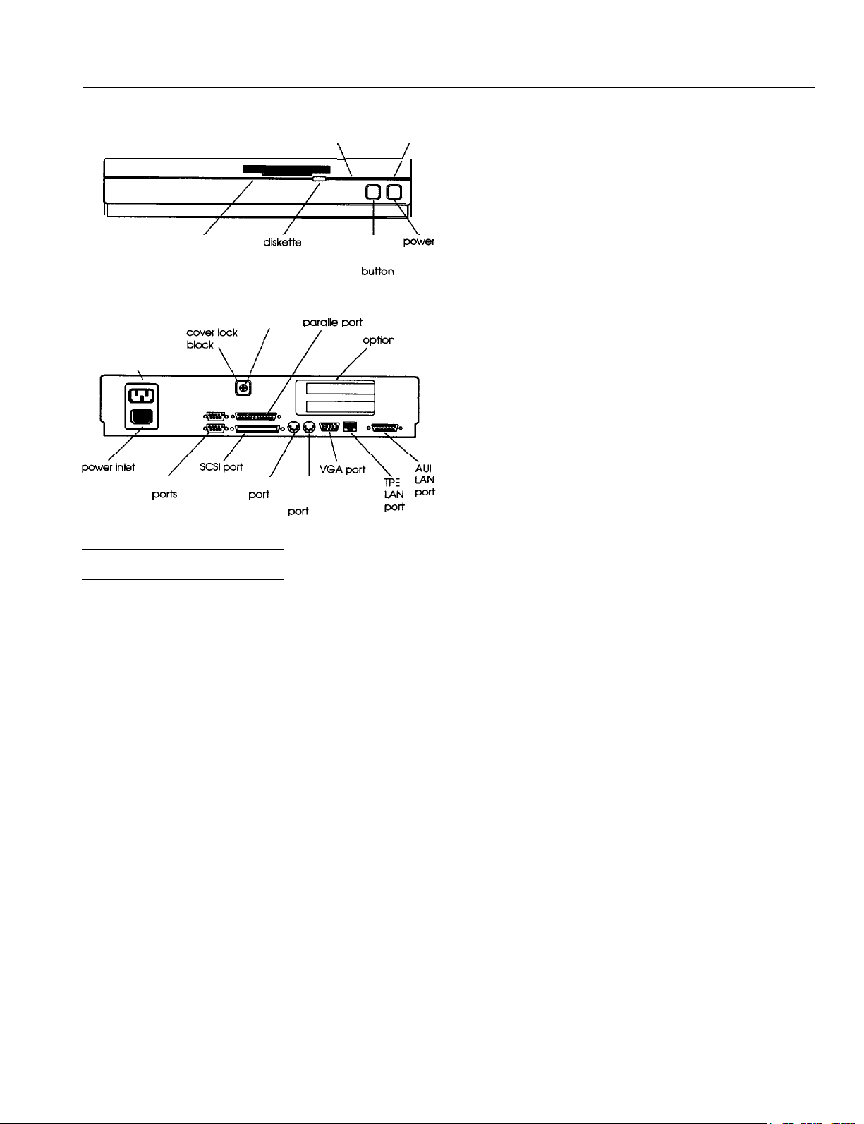
ExpressStation
diskette
access light
power outlet
\
serial
PO*
disk&e
release latch
cover
screw
mouse
’
I
port
Computer Specifications
CPU and Memory
CPU
System memory
BIOS
Video RAM
Cache memory
Math coprocessor
Intel 25 MHz 486SX, or 33 MHz 486DX
microprocessor; simulated 8 MHz
processor speed selectable through
software or keyboard command
4MB RAM standard on one 4MB SIMM;
expandable using 1MB, 2MB, 4MB, or 8MB
SIMMs up to 32MB (when 8MB SIMMs are
available); SIMMs must be 80ns, 36bit,
72-pin, gold-leaded, fast-page mode type
256KB two-part system BIOS including
video BIOS in two FLASH ROM devices;
write-protection available through jumper
and software
1MB standard
8KB internal cache integrated into the
microprocessor; optional 128KB Intel 485
Turbo Cache module can be installed on
main system board (128KB cache module
standard on 486/33 model); writethrough, two-way set associative cache
memory and controller; operation
controllable through software
Socket for optional Intel 25 MHz 487SX
coprocessor (allowable on 486SX/25
model only)
hard disk
access light
wrallel
/
keyboard
Doti
\.
oort
‘/“““on
power light
I
reset
button
/
poker
button
slots
Shadow RAM
Clock/calendar
Interfaces
Monitor
Parallel
serial
SCSI
LAN
Mouse
Keyboard
Option slots
Speaker
Controllers
Diskette
Hard disk
Video
Optional shadow RAM to copy system,
video, or external BIOS information from
ROM to RAM; software selectable
Socketed DS1287 real-time clock, calendar,
and 64-byte CMOS RAM for
configuration; integrated battery with
IO-year life
15-pin, D-shell analog connector; supports
standard VGA, multi-frequency, and highresolution monitors
25-pin, D-shell connector; supports IBM
AT compatible or PS/2 compatible
(bidirectional) signals; selectable through
software
Two RS-232-C 9-pin, D-shell connectors;
asynchronous; up to 56K baud rate
Internal connector for SCSI hard disk drive
on drive riser card (single-ended mode
only), terminator soldered onto riser card;
external SO-pin, fine-pitch connector on
back panel for up to seven external SCSI
devices (six if internal device is used);
external SCSI terminator included
One 15-pin AUI (Attachment Unit
Interface) D-sub connector; can connect
external MAU (Medium Attachment Unit)
to provide interface with other networks
One TPE (Twisted Pair Ethernet),
10BASET connector
Mini DIN, 6-pin connector for PS/2
compatible mouse or other pointing device
Mini DIN, 6-pin connector for PS/2
compatible keyboard
Two 32-bit EISA expansion slots (16-bit
and 8-bit ISA compatible) on option card
riser board
Internal speaker integrated into power
supply; programmable at I/O port 61h;
operation controllable through software
Controller on drive riser board supports
one 3.5 inch 1.44MB, third-height diskette
drive
Two interfaces on drive riser board
support either one IDE drive or one
internal SCSI hard disk drive; 3.5inch,
third- or half- height form factor
WD90C30 controller; supports resolutions
up to 1024 x 768 in 256 colors; compatible
with MDA, CGA, Hercules, EGA, and
VGA standards
ExpressStation Computer
11/2/92
ExpressStation-
Page 2
ExpressStation
LAN
Intel 82596CA, 64-byte transmit FIFO,
128-byte receive FIFO; 6-byte Ethernet
address per IEEE 802.3 standard stored in
writ+protectable FLASH ROM; 25 MHz or
33 MHz operation, based on CPU speed
SCSI
NCR
standard; internal FIFO (first-in-first-out),
32-bit address and data busses, internal
SCRIPTS processor with fast DMA; 25
MHz or 33 MHz operation, based on CPU
speed
Mass Storage Bays
Up to two internal devices maximum, one
third-height, 3.5-inch diskette drive bay;
one third- or half-height, 3.5-inch hard
disk drive bay for IDE or SCSI drive
Can connect up to seven optional external
SCSI devices to external SCSI connector
(six maximum if internal SCSI is used)
Keyboard
Detachable, two-position, 101 or 102
sculpted keys
Layout
Countrydependent main typewriter
keyboard; numeric/cursor control keypad;
four-key cursor control keypad; 12
function keys
5X700
I/O processor for SCSI-II
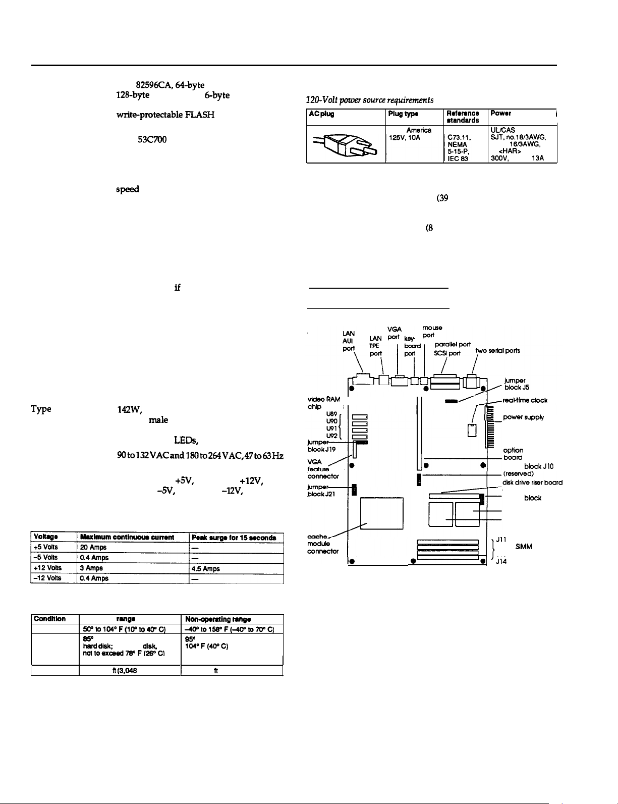
Power Source Requirements
I20-Volt
AC
power source requironents
PM
Plug m
North America
R*ferencr
etendards
ANSI
Physical Characteristics
Width
Depth
Height 3 inches
Weight
15.5 inches
(39
cm)
15 inches (38 cm)
(8
cm)
20 lb (9 kg) without peripheral devices
Main System Board Map
Powar
cord
UVCAS Listed, Type
SIT.
no.lEI3AWG.
or no. 16BAWG.
or
<HA&.
3OOV,
1 OA or
13A
I
Power Supply
we
Input ranges
Option slot
power limits
Power supply current ratings
pj
142W, fan-cooled, automatic input voltage
sensing male AC input socket, female AC
output socket; integrated power and reset
buttons, panel LEDs, speaker, and fans
9Oto132VACandX%Ito264VAC,47to63Hz
Maximum amperage for cards in both
option slots: at +5V, 6 Amps; at +12V,
2 Amps; at
-5V,
0.3 Amps; at
Environmental Requirements
Condition
Temperature
Humidity
Altitude
operating
60”to104°F(1Pto400C)
6!Y RH maximum with no
herd d&k; with herd
nottoexaed78oF(26oCI
1
wet bulb
1
to 10,000 it
rengo
(3.046
disk,
. .
m)
-l2V,
0.3 Amps
Non-apmting
-tol56“F(4U’toWC)
95O
RH maximum et
1M°F(40’C)
1
to 60.000 ft (15.240 m)
mnga
VIdeoRAM
chip sockets
0-O
reoHlme
‘I,
I- powr supply
c
0
Jll
J12
J13 sockets
‘Jli
clock
connector
option
card her
boord
jumper
bbck JlO
connector
jumper
bbck
J3
microprocessor
math coprocessor
socket
SIMM
ExpressStation-2
5/12/92 ExpressStation Computer
Page 3
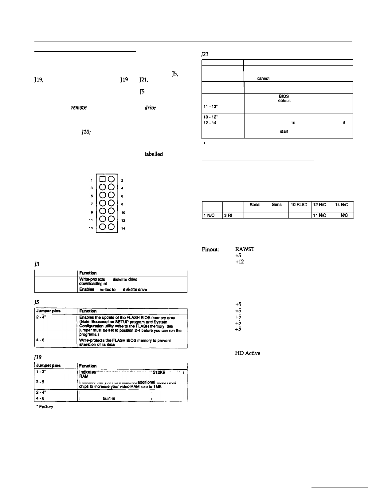
Main System Board Jumpers
The computer contains four blocks (groups) of jumpers: J3, JS,
119,
and J21. To access jumper blocks
remove any option cards that are installed. You must remove the
drive housing to access jumper blocks J3 and
Caution
Do not install or
remow
any option cards when the
removed from the computer. The housing stabilizes the option card riser
board and you could severely damage it if you put stress on it without
the support of the drive housing. Also, do not change the settings in the
reserved jumper block
JlO;
these jumpers must remain at their factory
settings.
Each jumper block consists of 14 jumper pins, as shown below.
Certain pin numbers and jumper functions are
each jumper block on the main system board.
119
and J21, you must
JS.
driw
labelled
housing is
beside
ExpressStation
121
Settings
1
Jumper pins
i-3’
3-5
2-4
4-6
9-11
11-13’
10-12’
12-14
*
Factory setting
Function
1
Enables you to use the BIOS SETUP program
Disables use of the BIOS SETUP program so unauthorized
users
canno
Clears the power-on password
Retains the power-on password
Clears the current
memory and sets delault parameters
Retains the current BIOS SETUP information in CMOS
memory
1
Sets normal FLASH memory operation
Sets the FLASH memory 10 operate in recovery mode
you unsuccessfully attempted lo download updated BIOS
information; allows
previous BIOS information
change the
settings you have chosen
BIOS SETUP information in CMOS
start of a procedure lo restore the
Main System Board Connectors
J1-Internal Serial Port 1 Header
Type: 3M style header, double row (Male)
2 GND
IN/C
4 DTR
3Rl
6 Serial 6
Data Out
5CTS 7RTS
ssrlal 10RLSD
Data In
9 DSR
I2N.C
11 tvc
14fvc
13
I1
N/c
The tables below list the jumper settings available in each jumper
block.
13
Settings
Jumper pins
2-4
4-6’
15
Settings
119
Settings
I
Jummr oins
*
Faclory setting
Function
Wrb-protecis
dow’nloadlng
Enebks
1 Funcilon
Indkntes
Indicates that you have installed
Enables the bulk-in VGA display adapter
Disables the
the dlhkstte drtve to prevent unauthorized
of software onto a diskette
all
writes 10
the diskette drive
that you are using the standard 512KB size video
additlonal
bulk-in
VGA display adapter
I
video RAM
J2-Power Connector
Type: Single Row Header Style (Male)
Pinout:
RAWST
1
+5
2
+12
3
-12
4
GND
5
GND
6
GND
7
GND
8
-5
9
+5
10
+5
11
+5
12
+5
13
+5
14
GND
15
GND
16
-12
17
HDActive
18
Front Panel Reset
19
Speaker Data
20
J4-Dual Serial Port Connector
Type: Stacked Dual 9-Pin D-sub (Male)
Pinout: PC AT standard
J6A-Parallel Port
Type: 25-pin Centronics type (Female)
Pinout: PC AT standard
ExpressStation Computer
5/12/92
ExpressStation-3
Page 4

ExpressStation
J6B-External SCSI Port Connector
Type: Fine pitch, 50 pin SCSI-2 (Female)
Pinout:
1
;
4
5
6
ii
9
10
::
13
::
GE
GND
GND
GND
GND
GND
GND
GND
EE
GND
N/C
GND
E%
Data 0
Data
1
Data 2
Data 3
Data 4
Data 5
Data 6
Data 7
Data Parity
GND
GND
GND
Terminator Power
GND
GND
SCSI Attn
GND
EE
GND
Ei :zy
SCSI Rst
~~
EKi
SCSI Msg
SCSI
se1
SCSI
CD
GND
GND
EE?
J8-PS/2 Mouse Connector
Type: PS/2 (Female)
Pinout:
1
Data
N/C
:
GND
4
5
&k
J17-Twisted Pair Ethernet Connector
Type:
RJ45
(Female)
Pinout:
1
TX+
TX-
2
3
RCV+
4
:::
2
RCV-
N/C
ii
N/C
J18-AUI Ethernet Connector
Type:
15pin
D-sub (Female)
DI-A
GND
WC
JXI-VESA
N/C GND
GND
VFAUI
Video Pass-thru Connector
GND DO-A
01-B
GND DO-B
Type: 3M style, double row header, 26 pin (Male)
-0
/CM61 1-2
GND
/GND1GND
WTC
BLANK
GND
/GND IGND /tvc
jLMt66 lOa4 IDat65 IDml66 /bt67
IDEN
VBHSU jVBVSR IQNO
SYNC EN
JWC
IWTCEN
Miscellaneous
Video Modes
Iruc
Cl-A
GND
Cl-B
GND
J15--PS/2 Keyboard Connector
Type: PS/2 (Female)
Piiutz
1
Data
2
N/C
3
G&ID
4
+5
Clock
i
N/C
7
EL%
t
GND
J16-VGA Video Connector
Type: 15-pin miniature D-sub (Female)
GND N/C
GND
N/C
verl.
Bw?c.
N/C
Blue
How.
Bvnc. N/C N/C
Green Red
GND GND
GND
ExpressStation-4
5/12/92
ExpressStation Computer
Page 5

ExpressStation
System Current usage
~~
i405 TurboCache
Cdntrotler
SlMMs (4 mod&as)
3.5’ 1.44 Meg
Fbppy
TEAC
Hard
drsk
drive
2
EISA Eqansim
Slots
1 cumn(-
Maxhumeyetem
1.2A(max)
(n-tax)
2.0 A
0.7 A (max)
0.75 A (max)
(mex)
6 A
]1765A(max)l .3A
.3A (ma)
syste?n I/o adires5 map
K)ddma
occo-ocFF
OCBB-OCBF Resewad
ocBo-oce7 LAN
OcB(McB3
ocsoc27
0033
OCCQ
04DD64Dl
04C264CF
040O-MS
M644465
0462
10461
o4ow4oF
03Feo3FF serislpatl
ozFoaF7
035663EF
03803DF
o37sowF
03
L
02F8-02FF Serialput
62F662E6 Gertprtrt4
027ecwF
OlFGOIF7
k22OCCO-OOOF
OOAWOAI
0x2
OC8OX06F
0070
007Mx)71
0070
0061
00
b!!Ez
Ftlnchl
SCSI
corltrd m@sters
amd regtsters
Syslem
Ward ID
UASIC regism (optll
cLAslcwntrolportc
UABlCWfltrolOOtlB
VFF
TO-0377 1
60,
BAA amtmk
r
DMA cmtmfter 2 extended
kllerNpedg~elcmtml
DMA
anlmlk
MAA high page
Lwt Bus
Wlware
1 ktendd
DMAoontmller 1 exterldedregisters
Fkppgdiskmrsronu
Serttport3
onboard vtdao controtbr
Peraltel
SewWary
Psw&t Lxxt
IDEtmerfawports
Numics~-r
DMA
dontrotter
lnterrud mntrotler 2
BASIC RXttml
DMA bwer page register
CLASIC
Reel-time
enable
NMI
NMI status
Oow(KqbwYmousaamtmtter
lnta& timer
Intmral tkllar 1
CLASIC
bytes (mad mty)
lacetoll. see
stop
m~isters
mgisters
2
extendd
redsters
mgtster
Master granted (read
NMI
moister hvrlte anM
NMI and m awtrol
port 1
Ftoppydiskoxrtrotter
2
2
pod A CLASIC
RtOS cormtar
ckxk
register (write
moister
2
index ragistars (r&&able
rnk)
moister
mty)
to
2.1 A Peak
0.00 A (max)
2 A
(max)
.3A
yodevke
NCR
53C7OiI
025QSCA
-7)
Oc26-Oc27) CLASIC
UASIC
CLASIC
CLABIC
62357
02357
02357
a!as7
62357
02357
azvT7
162367
62357
WD
16C552
02Q77AA
Exp.d
WD6DtXO
WD
16C552
I
Exp.d
WD
XC552
rn.a
EYnwrd
IDE
drnm
l4064647SX
62357
a2357
62357
UASIC
DS 1267
62357
62357
0742
62357
62357
(max)
System I/O address map
K)ddmu
w22-0023
0020-0021
00BWOF
Funstbn
DRAM
Inlefru~
DMA
omtmller
amtroller
ragsters
wntrdler
1
1
DMA Controller
Direct memory access (DMA) improves system performance by
allowing devices to access the system memory directly. This
ability is provided by two
82C37-compatible direct memory
access controllers (DMACs) contained in the 82357. The seven
independent 32-bit DMA channels are listed in the table below
along
with their associated DMA controller and their device
assignments.
DMA request
1
Level
DRQ 0 (CTRL1)
DRQ 1 (CTRL1)
DRQ 2 (CTRL1)
DRQ 3 (CTRL1)
DRQ 4 (CTRL2)
DRO
5
DRQ 6
DRQ 7 (CTRL2)
(CTRU)
(CTRK)
led
1 A~lgneddwlca
Spare
SDLC
Drskette drw
Spare
(Cascade for CTRL1)
Spare
Spere
spere
amtroller
System interrupts
1 Intemml
4
I
NM1
0
1
2
3
4
5
I
6
7
6
Q
10
11
12
IRQ 9,
on-board SCSI.
IRQ
systems,
systems,
boards have an
board is installed
1 FunctloMvstom ah
I
1 P&v
Error
Resewad, Intarval Timer
Reserved, Keyboard buffer full
Reserved.
Cascade Interrupt from slave PIC
on-w
serl
Port2
on-w
Serial
Porl
1
User available
On-W Floppy
On-W Parallel
RTC
optional SCSIAAN
Optbnal SCSI/LAN
Optbnal SCSI/LAN
On-W Mouse Port if enabled. else user available
Rasarvad.
User
Optional SCSILAN
10, 11, and 15 can ba set via the ECU for user available, on-board LAN, or
0, 1, 2, 6, and 13 canrwl bs
IRO
2 was
IRQ
2 IS not
optron
in an
Poll
(defautt
LAN)
(dafautl
SCSI)
Math
cnprosassor
avaitabta
used
avaitabte
avarlabta
to use
ExpressStatton
by an add-in card. In
br use m the XT bus. In PC-AT compatible
for use on the bus. Some
IRQ
2. This should not ba selected when such a
system.
PCKf
older
ISAexpansion
vorJevke
62352
02357
02357
/ EISA
/ buspIn
I
118
110
117
116
115
Q0
126
128
130
132
131
wmpattble
1
1
ExpressStation Computer
5/12/92
ExpressStation-5
Page 6

ExpressStation
System Memory Map
El22
OKB
512KS
639KB
WJKB
766KB
SOOKB
832KB
1
Notaltvideomodesare~~atthesametime.Ywcansavesomememocyby
defining which video
only
VGA
2
You can remap the vid6o BIOS to 0CXGW-l using the
System Conhguration utility il
at
requIrea It; thl6 6~6s
atways located
3 You oan shadow
OCOOOOH
Conttguration utility. The opbon
15KB boundary.
4
Borne memory managers, such as
area frwn
mntiguws
HexeMrees mngs Blw
0000-0000 to 0007-FFFF
000&0000
1 OC0NWJO
ooOA-0000
CWC-OOW
OOOG6OOO
OOOD-OOOO to COODFFFF
used
when you attach a monochrome monllor. Both the
modes
are ottan
th@ b+ii.
and ODFFFFH using the SETUP program or the system
09-FCOOH
memory above the area used by
to
OOOBFBFF
to
000%FFFF /
lo
OWB-FFFF
to
OOOG7FFF
to
OCOCFFFF
mod6s
you are using. Typicalty,
used
when you attach a VGA moniior.
Do
al
OWCOOH.
mrternal
ywr applicatii requwe
nc4
enable remapping to
32KB 01 memory for other
ROM BIOS intormatton to memory between
attcws
to a tower address in base memory to
512KB Base memory
1 KB
126KB
32KB
32KB
64KB
you to begin the shadow
QEMM-386,.
Fun6lton
127KB
Bese memory enabled in
SETUP or Svstem
1 Cfmfiguratloi uilllty
1 Extendad
BIOS data
segmenl
VW0
d&play RAM
Vi ROM BIOS
area (unused it video
shedow is disabled)
Built-in SCSI BIOS
(unused if SCSI is
disabled)
Unused (availabte tar
acmaon
card RAM/
OB-WOOH
OC-OCOOH
us66.
Tha built-in video BtOS is
move the exiendad BIOS data
M&DOS.
to
OS-7FFFH
taxi
and graphic
SEtUP
program or the
the video BIOS to reside
unless your
btook
povide
appticauon
more
at
6hadOW
is
aach
Hard Disk Drives
The following table lists the types of hard disk drives you can
use in your computer. Check this table and the manual that came
with your hard disk to find the correct type for the hard disk
drive(s) installed in your computer.
Note: Be sure you enter the correct drive type or
drive;
i,f they
are
incorrect, the computer will not recognize
parametersfor
ymr dti.
your
Hard disk drive
TYP w
01
(ifJ
- - _
14
19
20
21
22 1733
23 30s
24 903
25 776
26
27 698
26 976
35 834
35
37 683
38
3Q
40 960
typzs
305
1733
1612
I1024
1733
1733
-
-
548
761
uds
4
17
IA
17
15
17
I5
4
4
6 -1 33
-
7 330
5
16
16
6 -1
6 -1
10
I- I-
-
PC
126
/
-1
la
I.512
300
300
353
0
-1 46
- -
466
-1
-1
-1
-
/
17
seal
17
-
/ SIX6
/ 1OMB
/
user dehnable
I42MB
I 17
‘2nYR----i
17
1
17
1
17
I
17
17
17
17
17
3s 202MB
38
38 115MB
17
j-
I5SMB
13OMB
I42MB
I3OMB
IOMB
6lMB
WOMB
unused
40MB
40MB
124MB
unused
61MB
61MB
u6er definab4e
user definable
5/12/92 ExpressStation Computer
Page 7

ExpressStation
SIMM lnstallation
The
Express.%tion
4MB SIMM (single
comes with 4MB of memory provided by one
inline
memory module) installed on the main
system board. You can install additional SIMMs to increase your
computers memory to 32MB.
There are four SIMM sockets on the main system board. Each
socket can contain either a single-sided or doubl+sided SIMM.
The SIMMs must all be
t3Ons
(nanosecond), 3Gbit, 72-pin, gold-
leaded, fast-page mode SIMMs.
Be sure to follow these guidelines when you install SIMMs:
9
All SIMMs must be the same capacity
l
You can Install one, two, or four SIMMs; you cannot install
three SIMMs
l
Install multiple SIMMs for the best performance; for example,
install two 4MB SIMMs instead of one 8MB SIMM
l
Install the SIMMs in the sockets closest to the front of the
main system board first.
Note: To install 32MB of memory,
yaa
must remave the 4MB SIMM
that came with your system and installfour 8MB SIMMs when they
became available.
Error Codes and Messages
If the computer finds an error, it reports one of the following
types of error messages:
l
Power-on diagnostic and boot error messages
l
Error tone codes for fatal errors (that lock up the system)
l
Error tone codes for non-fatal errors (that do not lock up the
system).
Power-on Diagnostic and Boot Errors
When the
computer displays a message on the screen (as described below)
and the speaker beeps twice. If the error occurs before the
computer initializes the video display, the speaker sounds a
series of beeps (described in the next section).
Each error is identified by a message number and a countdown
number which the computer uses as it executes the test
associated with the error. For example, the following message is
countdown number 100 and error message number 0018:
The table below lists the power-on diagnostic and boot error
messages, and some basic solutions to the problems. Check the
appropriate section(s) in this appendix for other solutions.
100
poweron
lOO181:
Invalid confipxatim
diagnostic tests detect an error, the
informtim - pleaso mm SEmp
Power-on diagnostic and
Countdown
nuder
170
o30
EZY
/0041
0015
0021
I
0019
0020
0022
norm
ncne
none
hot
error messages
Error (Menage
1
Keyboard failure
1
Pomter
device failure
Hard
dusk
controller
rmmoh
optl0nal
Fl
NM
cache
ROM
locked
press
Eec
bad
Chedsum = nn
I
Tame
of day not set Run SETUP and set the time
Keyboard is
To
contmua
To enter SETUP message and
press
Enable
Enable
Eoct
Solutbn
1
de&er
1
wnnad~ons; contact your
dealer it problem
Run SETUP and check
Corracl
rep&a
contact
persists-
and date
Unlcck the keyboard
Press
Fl
instructions on the
run the SETUP program or
System Configuration
parsrsts
the address
the ROM
wur dealer II
to display the error
hollow
conflict OT
chip;
problem
the
screen
all
utiltty
i
to
Error Tone Codes
If power-on diagnostic tests detect an error but cannot display an
error message, the computer sounds an error tone code. The tone
code is a distinct pattern of beeps that identifies the error, such as
one beep-two beeps--one
computer locks up, but if the error is not serious (non-fatal) you
can continue using your computer.
The tables below list the fatal and non-fatal error codes.
beep. If the error is serious (fatal) the
ExpressStation Computer
5/12/92
ExpressStation-7
Page 8

ExpressStation
Error
tone
codes fo* fatal
/
Error
tono coda
I l-l-3
l-14
1-2-l
l-2-2
I
l-2-3
1-3-l
l-3-3
l-34
114-l
l-4-2
2-l -1
2-l -2
I 2-l-3
2-14
2-2-l
2-2-2
2-2-3
2-24
2-3-l
I
2-3-2
2-3-3
2-34
241
I 242
I243
244
3-l -1
3-l -2
3-l
3
3-l 4
3-24
1
D~~rimtion
1
Real-lime clock wrka/raad failure
ROM BIOS checksum faflura
Programmable lntenml
DMA
I DMA bade realster write/read
RAM refresh verifkatlon
First
First 64KB
I
First
First
Fkst 64KB RAM
First
First ft4KB RAM
First
First
FIrat
First
First
First
1
First
FM 64KB RAM
First B4KB
FM
Flrst 64KB f?AM
I
1 Flmt 64KB
First S4KB
Slave DMA mgister failura
Master DMA raaistar failure
Master
Slave intormpt mask register fallura
Keyboadhnouae mntmller
errors
timer
inftiaJlzat1on
S4KB
64KB RAM address line fatlure
S4KE
64KB RAM
S4KB
S4KE
S4KB RAM
64KB RAM
S4KB
64KE RAM
64KB RAM
S4KB RAM
failure
RAM
chip
RAM
oddleven kxtic fatlure
RAM
parity
faflura-btt 0
failure-bit 1
tailura-bit
RAM
faflure-bit
RAM
faflura-bft
failure-bft 5
fatlure-bft
RAM failure-bit 7
faflure-blt S
failura-bk
failure-bit A
RAM failure-bit
faflura-bit
fatlure-bit D
RAM
Cllurekk
RAM
fallura-bit
Memtpl
mask regfster lallura
failure
failure
faflure
or data
line
failure
(multffbii)
test In pmgress failure
2
3
4
6
9
B
C
F
F
test
faflure
Information Reference List
I
Engineering Change Notices
None.
I
Technical Information Bulletins
None.
I
Product Support Bulletins
None.
Related Documentation
I
TM-EXPRESS ExpressStation Service Manual
PL-EXPRE!SS
srKExrRE5s
Y743!I9100600
Y743!I9100300
Y74399100200 ExpressStation Setup Guide
I
I
ExpressStation Parts Price List
ExpressStation
ExpressStation
ExpressStation
Self Paced Kit
Usex’s
Software Guide
Guide
Ewor
tone codes
1
Error tono codaI
I 3-34
34-l
342
for
non-fatal errors
DOSC~~~ICNI
I Screen memom test
Screen
inhlaflzatfan
1
Soreen retmce test failure
hilure
test failure
I
ExpressStation-8
5/12/92
ExpressStation Computer
 Loading...