

Page 1
EPSON Equity 4+
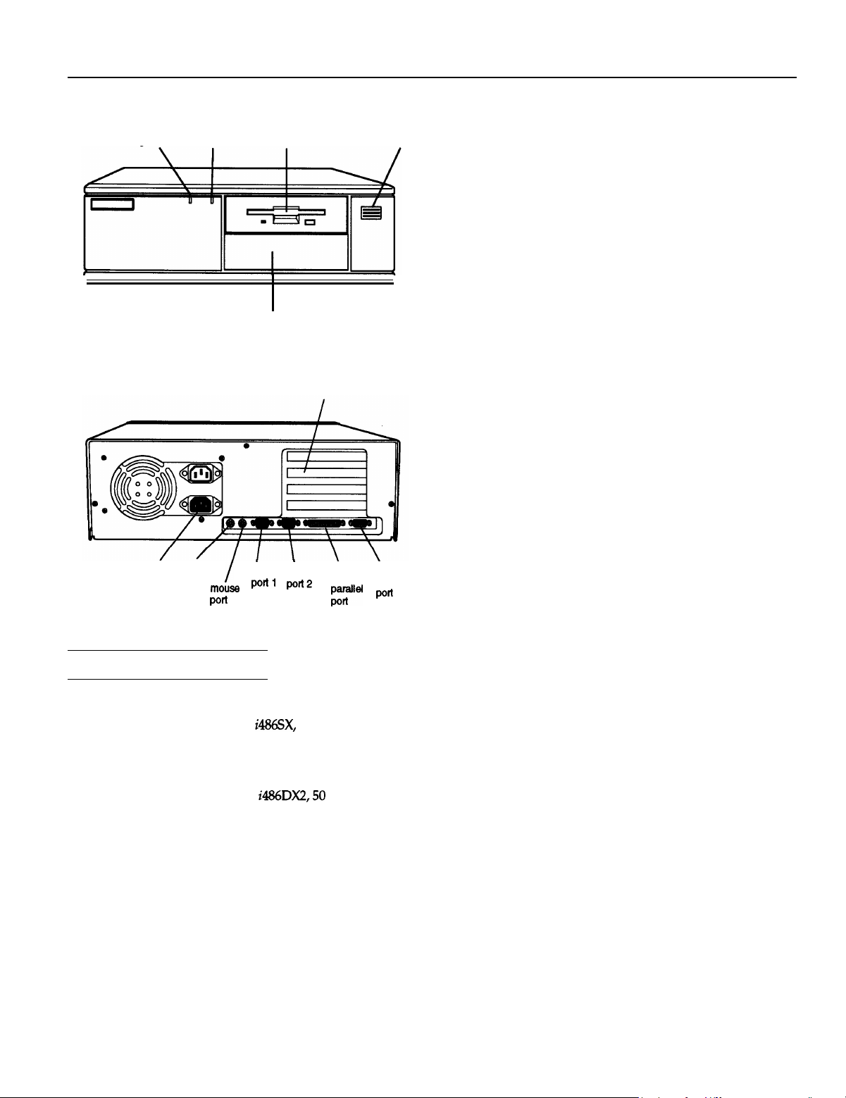
power
(SPEED)
light
power keyboard
inlet port
hard disk
access light
diskette
drive
bay for hard disk, diskette drive,
CD-ROM, tape drive, or other
option card slots
serial serial
POti’
\
power
button
VGA
monitor
Memory
ROM
Video RAM
Shadow RAM
Cache
Math
coprocessor
Clock/calendar
Controllers
Video
4MB RAM standard; expandable using
1MB, 4MB, or 16MB SIMMs to 36MB
(maximum); SIMMs must be 36-bit,
fast-page mode type with 70ns (or faster)
access speed
128KB system BIOS, video BIOS, and
SETUP code located in EPROM on main
system board
512KB DRAM on main system board,
expandable to 1MB using 256k x 4-bit
DRAM ZIPs
Supports shadowing of system and video
BIOS ROM into RAM
8KB of internal cache (built into the
microprocessor); expandable to 256KB
using 8KB or 32KB, 70ns SRAM DIP chips
On 4DX2/50 system, math coprocessor
built into the microprocessor; optional 487
upgrade available for 4SX/25 system
Real-time clock, calendar, and CMOS
RAM socketed on main system board with
built-in battery backup
Cirrus® Logic GD5422 VGA controller on
main system board; provides true color
resolutions up to 800 x 600 with 512KB
standard memory; with 1MB upgraded
memory, provides resolutions up to
1280 x 1024
Computer Specifications
CPU and Memory
32-bit CPU
System speed
4SX/25: Intel®
microprocessor in PGA-type CPU socket;
can be upgraded with optional 487SX/25
or ODP486-25 OverDrive™ processor
4DX2/50: Intel
microprocessor in PGA-type CPU socket
Fast and slow speeds available; fast speed
depends on CPU (25 MHz or 50 MHz),
slow is simulated 8 MHz speed; speed
selection through keyboard command; 0
wait state memory access at fast speed
To select slow speed, press the Ctrl, Alt,
and - keys simultaneously. To select
fast speed, press the
simultaneously. (Use the - or + key on the
numeric keypad.) Default system speed is
also user-selectable through SETUP
25 MHz
MHz
Ctrl,
Alt, and + keys
Diskette
Hard disk
Interfaces
Monitor
Parallel
Serial
Controller on main system board supports
up to two diskette drives or one diskette
drive and one tape drive
Interface on main system board supports
up to two IDE hard disk drives with
built-in controllers
VGA interface built into main system
board for analog or multifrequency VGA
monitor; 15-pin, D-shell connector
One standard 8-bit parallel, uni- or bi-
directional interface built into main system
board; I/O address selectable through
SETUP; 25-pin, D-shell connector
Two RS-232C, programmable,
asynchronous interfaces built into main
system board; 9-pin, D-shell connectors
10/1/93
EPSON Equity 4+ 1
Page 2
EPSON Equity 4+
Keyboard
Mouse
Option slots
Speaker
VGA feature
connector
Mass Storage
Diskette drives
Hard disk drives
Keyboard
Program
PS/2 compatible keyboard interface built
into main system board; num lock setting
selectable through SETUP; 6-pin, mini DIN
connector
PS/2 compatible mouse interface built into
main system board; 6-pin, mini DIN
connector
Four 16-bit (or S-bit) I/O expansion slots,
ISA compatible, 8 MHz bus speed; three
slots accommodate any size card,
bottom slot can hold reduced size card
(4.4 inch/110 mm)
Internal, piezo-electric speaker on main
board
IBM compatible VGA pass-through
interface built into main system board;
26-pin connector
Three half-height drives maximum configurable using
the following:
(high-density) capacity
5.25inch, 360KB (double-density) capacity
diskette drive: 3.5inch,
half-height
mounted horizontally
Half-height tape drive, CD-ROM, or other storage
device;
(high-density) capacity
720KB (double-density) capacity
factor hard disk
the first mounted vertically, second
or
and
up to
with mounting frames
Detachable, two-position height; 101 or 102
sculpted keys; countrydependent main
typewriter keyboard; numeric /cursor
control keypad; four-key cursor control
keypad; 12 function keys
Stored in ROM; accessible by pressing the
Delete
key at the SETUP prompt during boot
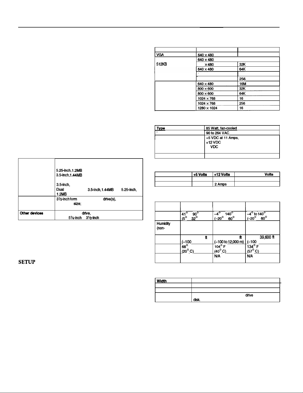
Video Modes
Mods
Extended,
memory required 640
Extended,
1 MB memory required
Resolution
800X600
800X600
Power Supply
Input ranges
Maximum outputs
-5
at 0.3 Amps,
Frequency
-12 VDC at 0.3 Amps
47 to 63 Hz
Option Slot Power Limits
Maximum current
For each slot
For all four slots
volts
7
Amps
11 Amps
1.5
Amps 0.3 Amps
Environmental Requirements
Condition
I
Temperature
condensing)
Attitude
Maximum
wet bulb (20°
Acoustical
noise
Operating
range range
to
to
20% to 90%
-330 to 9,900
37.5 dB(A)
C)
F
F
Nonoperating
to
to
10% to 90% 10% to 90%
-330 to 39,699
Physical Characteristics
Depth
Height
Weight
14.8 inches (370 mm)
16.5 inches (412 mm)
4.8 inches (120 mm)
16.7 b (7.5 kg), with one diskette drive and one hard
but without kevboard
colors
16
1256
16
-5 Volts and -12
0.3 Amps
Storage range
F
C)
to
330 to
140’ F
C)
EPSON Equity 4+ 2
10/1/93
Page 3
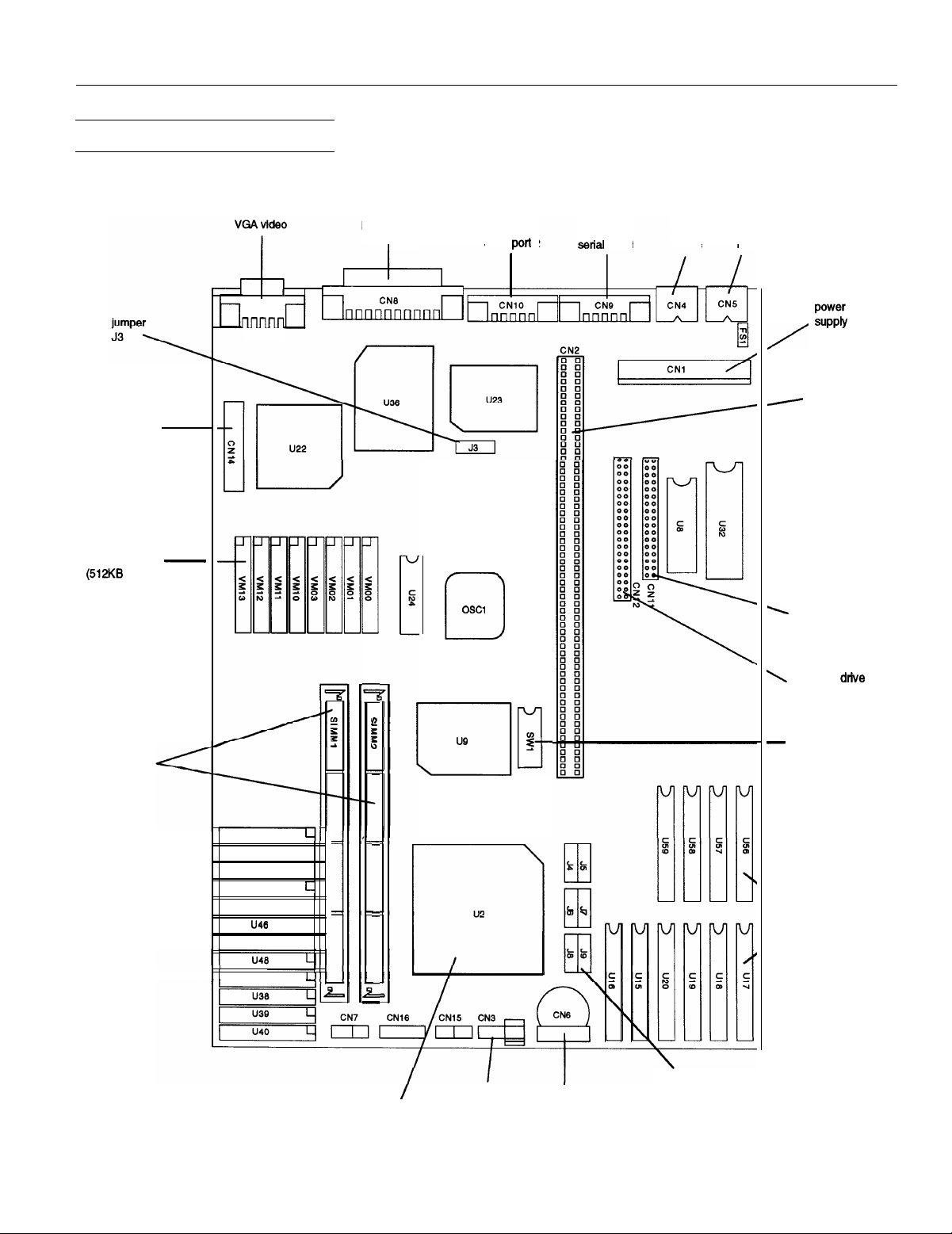
Main System Board Diagram
I
CN13
VGA feature
connector
parallel port
I
EPSON Equity 4+
serial port 2
connectors
option card
riser board
connector
video memory
optional)
SIMM
sockets
diskette drive
connector
hard disk
connector
DIP switches
u41
U42
u43
u44
u45
u47
,
u37
L
L
L
L
L
external
cache sockets
>
processor in
battery
connector
I
piezo-electric
PGA socket speaker
10/1/93
jumpers
J4-J9
EPSON Equity 4+ 3
Page 4

EPSON Equity 4+
Major Subassemblies
battery
CN3
I
diskette
drive
Connector Pin Assignments
drive bays
Serial Port Connectors (CN9 and CN10)
Serial Port Connector Pin Assignments
Signal
Pin
1
Data carrier detect
Receive data
2
3
Transmit data
Data terminal ready
4
5
Not used
Pin
Signal
6
Data set ready
7
Request to send
8
Clear to send
9
Ring indicator
Keyboard Connector (CN5) and Mouse Connector (CN4)
pin 6
pin 4
pin 2
Although the keyboard and mouse connectors are physically
identical, they cannot be used interchangeably.
pin 5
pin 3
pin 1
Parallel Port Connector
pin 13
I I
25
Parallel Port Connector Pin Assignments
Pin
Signal
1
Data 0
2
Data
3
4
5
6
7
8
9
*Active low logic
1
Data
2
Data
3
Data 4
Data
5 16
Data
6 17
Data
7 18 Signal
Pin Signal
ACK’
11
Busy
12
PE 21
13
Select
14
Auto’
15
ground
pin 1
Pin Signal
19
20 Signal
22 Signal
23 Signal
24 Signal
25 Signal
Signal ground
ground
ground
Signal
ground
ground
ground
ground
Pin
1
2
3
Signal
Data
Resewed
Ground
Pin
4
5
6
VGA Port Connector (CN13)
Din 5
pin 10
pin 15
VGA Port Connector Pin Assignments
Signal
(fused)
Clock
Reserved
pin 1
pin 6
pin 11
EPSON Equity 4+ 4
10/1/93
Page 5

EPSON Equity 4+
VGA Feature Connector (CN14)
pin
pin 2
VGA
‘Active low
Connector Pin Assignments
DMA Assignments
pin 25
pin 26
System I/O Address Map
clock NM
OAO
OCO
OF1
OF8
200
278
and
360
378
380
390
OBF
ODF
OFF
lF8
207
27F
2DF
2FF
363
37F
38F
393
controller 2,8259A
Clear math coprocessor busy
Reset math coprocessor
Math coprocessor
I Game
Parallel printer port 2
Alternate enhanced graphics
Data acquisition (adapter 0)
Serial port 2
Prototype
PC network (low address)
1 PC network (high address)
Parallel printer port 1
SDLC, bisynchronous
Cluster
(adapter 0)
2
adapter
t mask
Hardware Interrupts
10/1/93
(adapter 5)
(adapter 7)
addresses hex 000 to OFF are reserved for the system board
Hex 100 to 3FF are available on the system channel.
EPSON Equity 4+ 5
Page 6

EPSON Equity 4+
System Memory Map
23FFFFF
Extended memory
System BIOS
(Shadow RAM, 64KB)
Reserved for system BIOS (64KB)
OOEOOOO
oocoooo
oooooOO
Resewed for ROM on I/O cards
VGA BIOS ROM (Shadow, 32KB)
VGA Color Text
VGA Mono Text
VGA Graphics
Base memory
Hard Disk Drive Jumper Settings
Number
Conner
Conner
Quantum
l
CS (cable selection) is jumpered, the drive is a master if pin-28 is grounded
and a stave if pin-28 is not grounded.
Single Drive
C/D
DS
Drive
and DSP
DS
Slave
Drive
no jumpers
no jumpers
DIP Switch Settings
Switch
1
2
3
4
5
Factory setting
ON
OFF
ON
OFF
ON’ Enable password secutfty feature
Off
ON’ Select color monitor
OFF
Function
33 MHz CPU speed
25 MHz CPU soeed
25 MHz CPU speed
33 MHz
CPU present in PGA socket
CPU absent from PGA socket
Select monochrome monitor
l
* Factory set according to system type
speed
Processor Chips
The 4SX/25 system can be upgraded with an Intel OverDrive
processor on the main system board to effectively double the
internal clock speed of the computer’s microprocessor.
Alternatively, the 4SX/25 accepts the Intel 487SX/25
microprocessor with built-m math coprocessor.
SIMM lnstallation
Jumper and DIP Switch Settings
Display Adapter and CPU Jumper Settings
size
Setting
A’
B
A
B
Function
Enable the built-in VGA adapter
Disable the built-in VGA adapter so you can use a
d&play adapter on an option card as your primary
adapter
Select DX2 CPU
select sx CPU
Factory set according to system CPU
B
B
B
J7
A A
A
A A
B
Jumper
J4
Factory setting
External Cache Jumper Settings
Cache
OKB’
32KB A A
128KB
l
Factory setting; change jumpers only if external cache
A
A
A
are installed
The computer comes with 4MB of memory on the main
system board. To increase the amount of memory in the
computer up to 36MB, install 36-bit, fast-page mode SIMMs
that operate at an access speed of 70ns or faster, with a
capacity of 1MB, 4MB, or 16MB.
The following table shows the possible SIMM configurations;
do not install memory in any other configuration.
SIMM Configurations
SIMM1
0
4MB
4MB 4MB
4MB
l
Standard memory on the system board
SIMM2
4MB
0
Total
4MB’
8MB”
12MB
24MB”
I
EPSON Equity 4+ 6
10/1/93
Page 7

EPSON Equity 4+
Video Memory
If the computer has 512KB of video memory, you can install
four 256K x 4 bit, 70ns, 20-pin DRAM ZIP (Zig-zag Inline
Package) chips to increase the video memory to 1MB. The
following table lists compatible DRAM ZIP chips.
Supported Video ZIP Chips
Manufacturer
®
Micron
Part number
GM71
MT4C42562-6,
Cache Memory
Additional cache memory can be installed in eight sockets in
Bank 0 and Bank 1 on the main system board. The figure
below shows how the SRAM are distributed.
SRAM must,
match type \
in banks
\\
Hard Disk Drive Types
The table below lists types of hard disk drives supported by
the computer. Check this table and the hard disk manual to
find the correct type number(s) for the hard disk drive(s)
installed in the computer. Enter the type number(s) when you
set the hard disk drive configuration in the SETUP program.
Hard Disk Drive Types
8KB or 32KB SRAM chips can be installed. Bank 0 must be
filled before Bank 1. The SRAM type used for dirty RAM and
tag RAM must match the type installed in the banks. The
table below shows the possible configurations.
Cache Memory Configuration
Actual size when formatted may be slightly different than the size listed on the
l
drive label
Hard disk drive supported in translate mode
Epson drives
10/1/93
EPSON Equity 4+ 7
Page 8

EPSON Equity 4+
lnstallation / Support Tips
Mouse and Keyboard
When connecting the mouse and keyboard to the
computer, be careful to plug them into the proper ports.
Although the ports are physically identical, they are not
interchangeable, and damage may occur to the main
system board if you plug the connectors into the wrong
ports.
Installing Diskette Drives
Make sure that the drive type has been correctly selected
in the SETUP program.
Installing Hard Disk Drives
It is recommended that a 16-bit, AT-type hard disk
controller be used if you are installing a drive that cannot
use the embedded IDE interface. If you install a non-IDE
hard disk drive and controller card, you need to use the
SETUP program to disable the built-in IDE hard disk drive
interface.
When installing a hard disk drive, see the hard disk drive
types table on page 7 and use the SETUP program to select
the correct type number for the drive. You can select a
type number that matches the parameters for the drive or
a type number with parameters having lesser values, as
long as they do not exceed the maximum capacity (in MB)
of the drive. If there is no match for the drive, you can
select a user-defined drive type (47) and enter the drive’s
exact parameters.
Software Problems
When installing a copy-protected software package, first
try the installation at fast speed. If this does not work
properly, select slow speed by pressing the Ctrl and Alt
keys and the - key on the numeric keypad
simultaneously. Try loading the program at slow speed
and then switching to fast speed, if possible.
When using a software package that uses a key disk as its
copy-protection method, try loading it at fast speed. If this
does not work, load it at slow speed.
Password
Make sure that you do not forget the password you set up.
If you do:
1.
Disable it by setting DIP switch 4 on the main system
board to OFF.
2.
Then turn the computer on and off again.
3.
Set DIP switch 4 to ON to enable the password function.
4.
Run SETUP to enter a new password, if desired.
Users can enter a hot key designation in SETUP to secure
the system from unauthorized users. Once a password
and hot key have been set, when the hot key is pressed,
the keyboard and mouse lock until the user enters the
password.
Booting Sequence
If you cannot boot the computer from the hard disk drive,
make sure the booting sequence in the SETUP program is
set to A, C. Then boot the computer from a system diskette
in drive A.
Information Reference List
Engineering Change Notices
None.
Technical Information Bulletins
None.
Product Support Bulletins
None.
Related Documentation
TM-EQ4+
PL-EQ4+ Epson Equity 4+ Parts Price List
400264700
Epson Equity 4+ Service Manual
Epson Equity 4+ User’s Guide
EPSON Equity 4+ 8
10/1/93
 Loading...