

Page 1
User's Guide
Page 2
Notations Used in This Guide
Safety indications
The documentation and the projector use graphical symbols to show how to use the projector safely.
The indications and their meaning are as follows. Make sure you understand them properly before reading the guide.
Warning
Caution
General information indications
Attention
a
s Indicates a page where detailed information regarding a topic can be found.
[Name] Indicates the name of the buttons on the remote control or the control panel.
Menu Name Indicates Configuration menu items.
This symbol indicates information that, if ignored, could possibly result in personal injury or even death due to incorrect handling.
This symbol indicates information that, if ignored, could possibly result in personal injury or physical damage due to incorrect handling.
Indicates procedures which may result in damage or injury if sufficient care is not taken.
Indicates additional information and points which may be useful to know regarding a topic.
Example: [Esc] button
Example:
Select Brightness from Image.
Image - Brightness
Page 3
Safety Warning and Cautions
3
Make sure you read the following before you use the projector.
s
Safety Instructions
Warning and Cautions on Installation
Warning
This is a class A product. In a domestic environment this product may cause
radio interference in which case the user may be required to take adequate
measures.
Do not use or install the projector where it may be subject to water or rain,
or high humidity, such as outdoors, in a bathroom, or shower room, and so
on. Otherwise, it could cause a fire or electric shock.
Do not install in locations where salt damage could occur, or in locations
subject to corrosive gas such as sulphuric gas from hot springs. Otherwise,
corrosion could cause the projector to fall. It could also cause the projector to
malfunction.
Note the following points when installing on a ceiling (ceiling mount) or in a
high location. If installation work is not carried out correctly, the projector
could fall down. This may result in injury or accidents.
- Since special techniques are required to install the projector on a ceiling
and to handle the ceiling mount, make sure you contact a professional.
- Secure the mount with bolts using the handle securing section (6
points) on the top or base of the projector.
- To prevent the projector from falling, thread sufficiently strong wire
rope and so on through the ceiling mount and secure to the ceiling.
Warning
Do not tie the power cord and other connection cables together. Otherwise, it
could cause a fire.
Only use the specified power-supply voltage. Otherwise, it could cause a fire
or electric shock.
Be careful when handling the power cord. Otherwise, it could cause a fire or
electric shock. Note the following when handling the power cord.
- Do not plug multiple power cords in a single electric outlet.
- Do not plug in the power cord if there are any foreign substances, such
as dust, stuck to it.
- Make sure you insert the power cord all the way in.
- Do not plug in or unplug the power cord with wet hands.
- Do not pull the cord when unplugging the power cord. Make sure you
hold it by the plug.
Do not use a damaged power cord. Otherwise, it could cause a fire or electric
shock. Note the following when handling the power cord.
- Do not alter the power cord.
- Do not place any heavy objects on the power cord.
- Do not bend, twist, or pull the power cord forcibly.
- Do not layout the power cord near a heating device.
Do not place flammable objects in front of the lens. If you set the schedule to
turn on the projector automatically, any flammable objects placed in front of
the lens could cause a fire.
Page 4
Safety Warning and Cautions
4
Warning
Do not cover the projector'sair intake vent or air exhaust vent. If either of the
vents is covered, the internal temperature could rise and cause a fire.
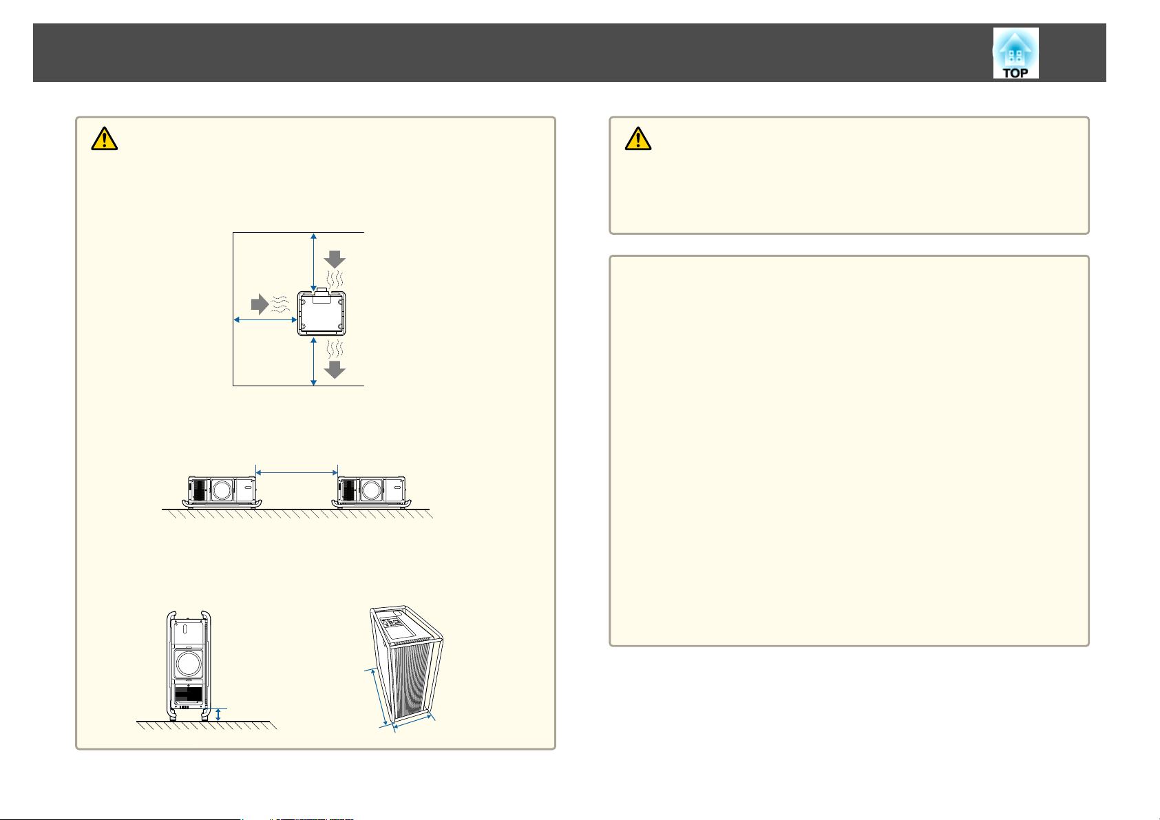
Make sure you secure the following space around the projector so as not to
block the air intake vent and air exhaust vent.
500mm
500mm
500mm
When setting up multiple projectors, make sure there is a gap of at least 200
mm between the projectors. Also, make sure that the heat from the air
exhaust vent does not go into the air intake vent.
200mm
When installing the projector with the air intake vent facing down, make sure
there is a gap of at least 100 mm between the projector and the floor and so
on. Make sure there is a space of 800 x 350 mm for the base so that the air
intake vent is not blocked.
Caution
Do not place the projector on an unstable surface, such as on an unstable table
or tilted surface. Install the projector appropriately to prevent the projector
from falling.
Otherwise it may cause an injury.
Attention
Do not install the projector in a location that is subject to vibration or
shock.
Do not install the projector near a high-voltage line or object that generates
magnetism. Otherwise the projector may not work correctly.
Do not use or store the projector in a location that is subject to extreme
temperatures. Also, avoid sudden temperature changes.
Make sure you use or store the projector in a place that is within the
operating or storage temperature ranges.
s "Projector General Specifications" p.270
Do not install the projector in direct sunlight.
If the projector is in direct sunlight, the internal temperature increases, which
could cause parts such as the surface of the projection lens or the built-in
camera to deteriorate.
When installing the projector in an environment in which a high-powered
laser beam is being used, make sure it is installed so that the laser beam does
not hit the surface of the projection lens.
When using at an altitude that exceeds 1,500 m, set High Altitude Mode to
On.
s Extended - Operation - High Altitude Mode p.147
100mm
800mm
350mm
Page 5
Safety Warning and Cautions
5
Attention
You may need dedicated installation mounts to tilt and install the projector.
Contact a specialist and prepare the mount.
- Plan so that the mount does not fall.
- Make sure the mount is strong enough to support the projector.
- When attaching a mount to the projector, secure the mount with bolts
using the handle securing section (6 points) on the top or base of the
projector.
Note the following points when installing a projector directly on top of
another. This projector can be installed on top of another projector that has
the carrying handles attached to the top.
- Do not stack three or more projectors (you can stack up to two
projectors).
- Install the feet in the indentations on the top at the four corners.
- Do not remove the feet on the bottom of the projector.
Except for the projector's parts, do not place anything on the projector.
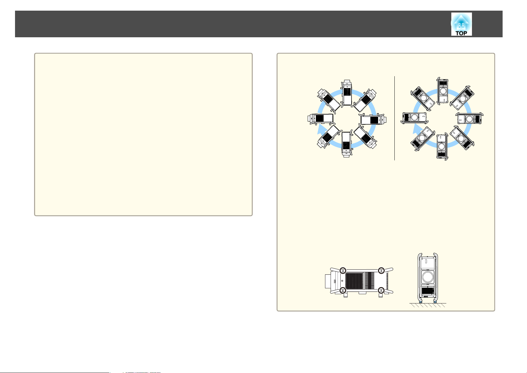
a
The projector can be installed at any angle. There is no vertical or
horizontal limit to how the projector can be installed.
We recommend setting the focus, zoom, and lens shift at least 20
minutes after you start the projection, because images are not stable
right after turning on the projector.
When using a projector with an air filter on the ceiling side, the air
filter will become clogged frequently. Clean the air filter regularly.
"Cleaning the Air Filter and Air Intake Vent" p.216
s
You can install the projector in a portrait orientation by attaching
the carrying handles to the top and bottom of the projector. You can
remove the feet from the projector and attach them to the carrying
handle.
Page 6
Safety Warning and Cautions
6
Cautions on Lifting
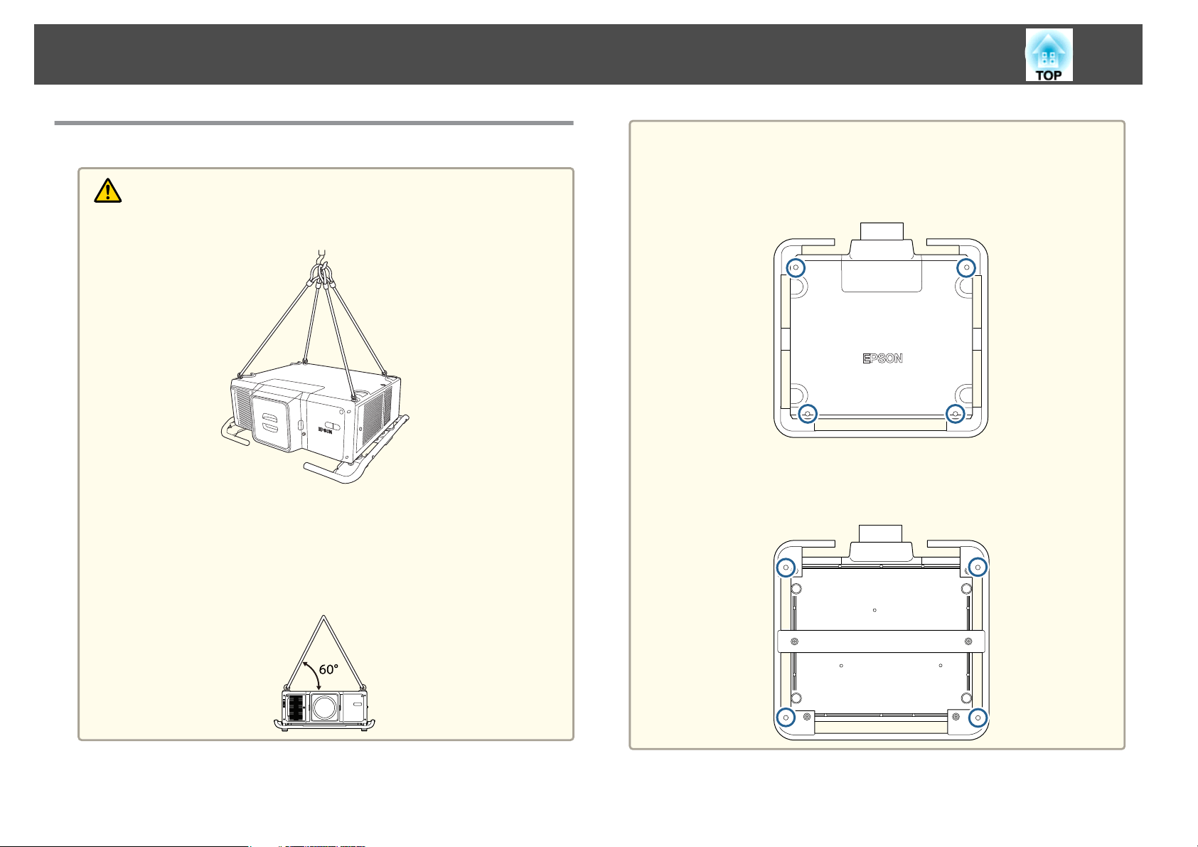
Caution
Use the four eye bolts installed on the same surface of the projector to lift
it.
Only use the eye bolts when temporarily transporting the projector and not
for permanent installation. The projector could be damaged or could
malfunction.
Do not lift the projector with the front/back/side of the projector facing
up.
Make sure that the angle when lifting is 60 degrees or more.
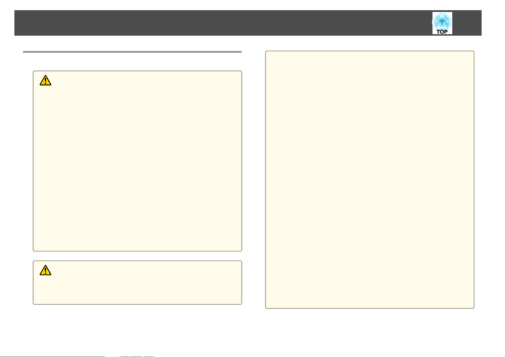
Attention
When attaching directly to the projector
Use four commercially available eye bolts M8 (ankle length 11 to 16 mm) and
attach them to the four screw holes for eye bolts.
When attaching to the handle
Use four commercially available eye bolts M10 (ankle length 11 mm or more)
and attach them to the four screw holes for eye bolts on the handle.
Page 7
Safety Warning and Cautions
7
Warning and Cautions on Usage
Warning
Do not cover the projector's air intake vent or air exhaust vent. If either of
the vents is covered, the internal temperature could rise and cause a fire.
Do not look into the lens while projecting. The powerful light emitted could
cause damage to eyesight. Take particular care when there are children
present. When turning on the projector at a distance using the remote
control, make sure there is no one looking into the lens.
During projection, do not block the light from the projector with the lens
cover (removable) or a book and so on.
If the light from the projector is blocked, the area on which the light shines
becomes hot which could cause it to melt, burn, or start a fire. Also, the lens
may get hot due to the reflected light which could cause the projector to
malfunction. To stop projection, use the Shutter function, or turn off the
projector.
Do not open the projector's case. Never disassemble or remodel the projector.
There are high-voltage components inside the projector that could cause fire,
electric shock, or an accident.
If an error occurs, disconnect the power cord from the electrical outlet, and
contact your local dealer or the nearest address provided in the Epson
Projector Contact List. If you continue using the projector as it is, it could
cause an electric shock, fire, or even damage to eyesight.
s Epson Projector Contact List
Caution
Do not place objects that may become warped or otherwise affected by heat
near the air exhaust vent and do not put your face or hands near the vent
while projection is in progress.
Attention
When you purchase the projector, a protective cap is installed in the lens unit
installation section. Install the protective cap when you are not using the
projector. If dust or dirt enter the projector, projection quality deteriorates
and it could cause a malfunction.
When a high-powered laser beams through the surface of the projection lens
or the built-in camera, it can cause a malfunction. If the laser beams through
the surface of the projection lens or the built-in camera, block the laser beam
with non-permeable or incombustible aluminum foil or metal plates such as
iron to protect the projection lens and the built-in camera. You can also use
the projector's Shutter function to prevent the LCD panel from being
damaged by laser light.
Try not to touch the lens section with your hand or fingers. If fingerprints or
oils are left on the surface of the lens, projection quality deteriorates.
If you continue to project while the surface of the lens is dirty, projection
quality deteriorates. Make sure you clean the lens.
s "Cleaning the Lens" p.216
Store the projector with the protective cap installed. If the projector is stored
without the protective cap, dust and dirt may get inside the projector and
cause malfunctions or lower the quality of projection.
When storing, make sure you remove the batteries from the remote control.
If the batteries are left in the remote control for an extended period of time,
they may leak.
When using the projector in smoky environments such as at events and so
on, make sure you replace the air filter after approximately 240 hours of use.
(This is a guideline when using the projector in an environment with an
atmospheric concentration of ondina oil of approximately 0.000000013%. The
air filter replacement time may be shorter depending on the operating
environment.) Using the projector in a smoky environment may cause the
filter's dust collection function to decline and dust may adhere to the inside
of the projector or the power supply; this may cause a malfunction to occur.
s "Replacing the Air Filter" p.221
Page 8
Safety Warning and Cautions
8
a
About the LCD panel
- The LCD panel may contain pixels that are missing or appear bright all
the time. This is not a sign of an error.
- If you project a still image or an image that does not move much for a
long time, the image may remain as an afterimage. This is due to the
properties of the LCD panel and is not a malfunction. You need to run
Refresh Mode to solve this issue.
s Reset - Refresh Mode p.163
About the light source
The projector uses a laser as the light source. The laser has the
following characteristics.
- Depending on the surroundings, the brightness of the light source may
decline. The brightness declines a lot when the temperature gets too
high.
- The brightness of the light source declines the longer it is used. You can
change the relationship between operation time and decline in
brightness in Brightness Settings.
s "Relationship between Brightness Level and light source operation
time" p.76
a
About light source calibration
-When Run Periodically is set to On for Light Source Calibration, every
time the usage time reaches 100 hours, calibration starts automatically
for the light source when the projector is turned off. However, light
source calibration does not start automatically in the following
situations.
Within 20 minutes of turning on the projector
When using the Shutter function
Within 20 minutes of releasing the Shutter function
When the projector is used continuously for over 24
hours
When using direct shutdown
- When performing Light Source Calibration, the differences in the
White Balance and the Brightness Level for the light source are
corrected.
s Reset - Light Source Calibration - Run Periodically p.163
Page 9
Safety Warning and Cautions
9
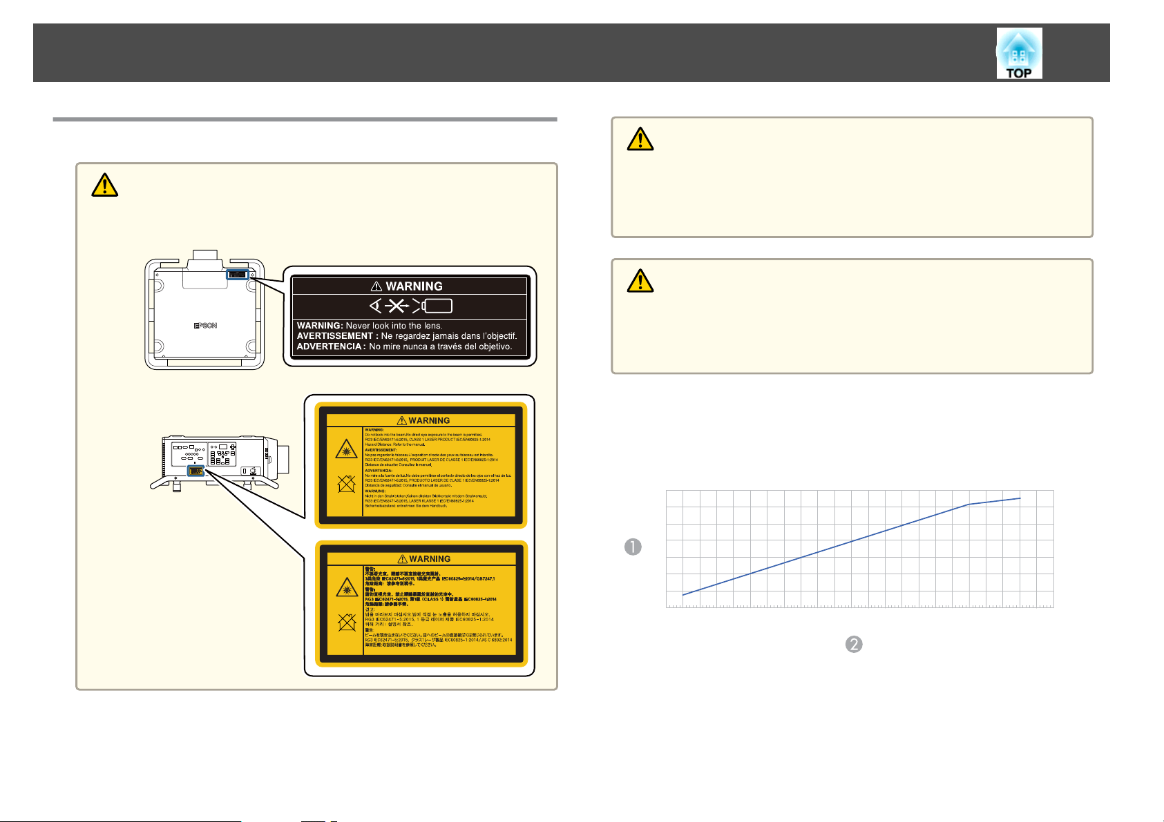
Warning and Cautions on the Laser
Warning
Laser warning labels are attached to the projector.
Top
Side
Warning
Do not open the projector's case. The projector contains a high-powered
laser.
Possibly hazardous optical radiation emitted from this product. Do not look
at operating light source. Eye injury may result.
Caution
This projector is a Class 1 laser product that complies with the IEC/
EN60825-1:2014 international standard for lasers.
Do not disassemble the projector when disposing of it. Dispose according to
your local or national laws and regulations.
Hazard Distance according to IEC62471-5:2015
Looking into the lens at distances closer than those indicated here can cause
damage to eyesight.
7
6
5
4
3
2
1
0
0 2468
1357
0.5 1.5 2.5
3.5
4.5 5.5 6.5 7.5 8.5 9.5 10.5910
11 11.5
Hazard distance (Units: m)
A
Throw ratio
B
Page 10
Safety Warning and Cautions
Notes on Carrying and Transporting
There are many glass parts and precision components inside the projector.
To prevent damage due to impacts when carrying and transporting, handle
the projector as follows.
Before carrying or transporting, make sure you read the supplied Transport
and Installation Handbook.
Caution
The projector should not be carried by one person. At least four people are
needed to unpack or carry the projector.
Attention
Prepare the following before carrying the projector. Check the Transport and
Installation Handbook for more information.
Turn off the power to the projector and disconnect all cables.
When moving nearby without having to pack-up the projector, install the lens
cap on the lens unit.
When packing up and transporting the projector, remove the lens unit and
install the protective cap on the lens unit installation section.
Enclose the projector securely in packaging material to protect it from shock,
and place it into a strong container. Be sure to notify the carrier company
that it is precision equipment and that it needs to be kept horizontally during
transportation.
10
Page 11

Contents
11
Notations Used in This Guide ........................ 2
Introduction
Part Names and Functions .................................. 17
Front/Top...................................................17
Rear/Side...................................................18
Base ...................................................... 19
Handle ...................................................20
Connector Ports ..............................................20
Control Panel ................................................22
Remote Control...............................................23
Handy remote control operations................................ 25
Replacing the remote control batteries ............................. 26
Remote control operating range................................. 27
Connecting a cable to the remote control ........................... 27
Preparing the Projector
Installing the Projector ..................................... 30
Removing and Attaching the Projector Lens Unit ........................ 30
Attaching................................................. 30
Lens Calibration............................................32
Removing .................................................33
Installation Settings ............................................ 34
Changing the direction of the image (projection mode).................34
Screen Settings ............................................... 34
Adjusting the position of the image on the projected screen ..............35
Displaying the Test Pattern ....................................... 36
Adjusting the Position of the Projected Image (Lens Shift Adjustment).........37
Adjusting the Image Size ........................................ 39
Correcting the Focus........................................... 40
Correcting Distortion (Image Warping).............................41
Registering and Loading Lens Adjustment Values .......................42
ID Settings ..................................................43
Set the projector ID..........................................43
Checking the projector ID ...................................... 44
Setting the remote control ID................................... 44
Setting the Time ..............................................44
Other Settings................................................46
Settings related to basic operations............................... 46
Settings related to display ......................................46
Connecting Equipment ..................................... 48
Connecting a Computer......................................... 48
Connecting Image Sources.......................................50
Connecting to an External Monitor..................................52
Connecting a LAN Cable......................................... 53
Connecting an HDBaseT Transmitter................................ 54
Installing the Wireless LAN Unit .................................... 55
Basic Usage
Turning On the Projector ................................... 57
Turning Off the Projector ................................... 59
Projecting Images ......................................... 60
Automatically Detecting Input Signals and Changing the Projected Image (Source
Search) ....................................................60
Switching to the Target Image.....................................61
Adjusting Projected Images ................................ 62
Correcting Distortion in the Projected Image ...........................62
H/V-Keystone ..............................................63
Quick Corner...............................................64
Curved Surface.............................................65
Corner Wall ................................................ 69
Point Correction............................................ 72
Selecting the Projection Quality (Selecting Color Mode)...................74
Setting the Brightness.......................................... 75
Guide to Estimated Remains ....................................76
Relationship between Brightness Level and light source operation time . . . . . . 76
Page 12

Contents
12
Setting the Amount of Light of the Projected Image ......................77
Changing the Aspect Ratio of the Projected Image.......................78
Changing methods.......................................... 78
Adjusting the Image ...........................................79
Hue, Saturation, and Brightness adjustment .........................79
Gamma adjustment.......................................... 80
Adjusting Image Resolution (Image Enhancement) .......................81
4K Enhancement............................................ 81
Image Preset Mode.......................................... 82
Frame Interpolation ..........................................82
Noise Reduction ............................................83
MPEG Noise Reduction ........................................83
Super-resolution ............................................ 84
Detail Enhancement .........................................84
Useful Functions
Multi-Projection Function . ................................. 87
Adjustment Procedure.......................................... 87
Adjusting automatically online ..................................87
Adjusting manually offline..................................... 88
Tiling ......................................................89
Performing tiling automatically..................................89
Performing tiling manually .....................................90
Edge Blending ...............................................91
Black Level .................................................. 93
Area Correction .............................................94
Screen Matching .............................................. 95
Operating conditions for auto adjustment functions ....................96
Automatically correct the brightness and tint for multiple projectors........96
Color Matching............................................. 97
Displaying a Scaled Image .......................................98
Using Tiling Function of Geometry Correction Assist..................... 100
Operating conditions for auto adjustment functions ...................100
Using the Stacking Function of Geometry Correction Assist ................ 101
Operating conditions for auto adjustment functions ...................101
Projection Functions ...................................... 103
Projecting Two Images Simultaneously (Split Screen).................... 103
Input Sources for Split Screen Projection...........................103
Operating procedures ....................................... 103
Restrictions during split screen projection..........................105
Hiding the Image Temporarily (Shutter)............................. 106
Freezing the Image (Freeze)..................................... 107
Saving a User's Logo ........................................... 107
Memory Function ......................................... 109
Saving/Loading/Erasing/Resetting the Memory........................ 109
Scheduling Function ...................................... 111
Saving an Event..............................................111
Setting an Event ........................................... 111
Checking an Event.......................................... 112
Editing an Event ........................................... 113
Security Functions ........................................ 115
Managing Users (Password Protection).............................. 115
Kinds of Password Protection.................................. 115
Setting Password Protection................................... 115
Entering the password....................................... 116
Restricting Operation .......................................... 117
Control Panel Lock ..........................................117
Lens Lock ................................................ 118
Remote control button lock....................................118
Anti-Theft Lock .............................................. 119
Installing the wire lock....................................... 119
Using the Projector on a Network
Wired Network Projection ................................. 122
Selecting Wired Network Settings ................................. 122
Wireless Network Projection . . ............................. 124
Selecting Wireless Network Settings Manually ......................... 124
Page 13

Contents
13
Selecting Wireless Network Settings in Windows ....................... 126
Selecting Wireless Network Settings in Mac........................... 126
Setting Up Wireless Network Security ............................... 127
Supported Client and CA Certificates............................. 129
Using a QR Code to Connect a Mobile Device.......................... 129
Using a USB Key to Connect a Windows Computer ...................... 130
Setting a Static IP Address Using the LCD Display ............ 132
Secure HTTP ............................................. 133
Importing a Web Server Certificate Using the Menus.....................133
Supported Web Server Certificates ...............................134
Setting a certificate using a Web browser .......................... 134
Configuration Menu
Configuration Menu Operations ........................... 137
List of Functions .......................................... 138
Configuration Menu Table...................................... 138
Network menu............................................ 140
Image Menu................................................ 141
Signal Menu ................................................ 143
Settings Menu ...............................................145
Extended Menu ..............................................147
Network Menu .............................................. 151
Notes on operating the Network menu ............................ 153
Soft keyboard operations ..................................... 153
Basic menu............................................... 154
Wireless LAN menu......................................... 154
Wired LAN menu ........................................... 158
Notifications menu ......................................... 159
Others menu ..............................................160
Reset menu...............................................161
Info Menu (Display Only)........................................161
Reset Menu.................................................163
Batch Setup .............................................. 165
Setup Using a USB Flash Drive .................................... 166
Saving settings to the USB flash drive ............................. 166
Reflecting saved settings to other projectors ........................ 168
Setup by Connecting the Computer and Projector with a USB Cable . . . . . . . . . . 169
Saving settings to a computer.................................. 169
Reflecting saved settings to other projectors ........................ 171
When Setup Fails .............................................172
Troubleshooting
Using the Help ........................................... 174
Reading the Indicators . . . . . . .............................. 175
Understanding the Status Information ..................... 182
Checking the Status........................................... 182
Understanding the screen ..................................... 183
Setting the screen display (LCD) ................................. 184
Explanations of the Display Content................................185
Problem Solving .......................................... 200
Problems Relating to Images ..................................... 201
No images appear .......................................... 201
Moving images are not displayed ................................202
Projection stops automatically ..................................202
Not supported is displayed.................................... 202
No Signal is displayed........................................202
Images are fuzzy, out of focus, or distorted......................... 203
Interference or distortion appear in images ......................... 203
The image is truncated (large) or small, the aspect is not suitable, or the image has
been reversed .............................................204
Image colors are not right ..................................... 205
Images appear dark ......................................... 206
Automatic adjustments are not performed correctly................... 206
Problems when Projection Starts .................................. 208
The projector does not turn on................................. 208
Other Problems.............................................. 209
There are afterimages (screen burn-in) in the projected image . . . . . . . . . . . . 209
Page 14

Contents
14
The remote control does not work............................... 209
Cannot control correctly using Art-Net............................ 210
Nothing appears on the external monitor .......................... 210
I want to change the language for messages and menus ................ 211
Email is not received even if a problem occurs in the projector ............ 211
The battery that saves your clock settings is running low. is displayed ....... 211
The projector did not turn off correctly. is displayed................... 211
Detailed logs and error message are not displayed .................... 212
About Event ID ........................................... 213
Maintenance
Cleaning the Parts ........................................ 216
Cleaning the Projector ......................................... 216
Cleaning the Lens............................................ 216
Cleaning the Air Filter and Air Intake Vent ............................ 216
Cleaning the air filter ........................................ 217
Cleaning the air intake vent ....................................220
Replacing Consumables ................................... 221
Replacing the Air Filter......................................... 221
Air filter replacement period ................................... 221
Replacing the air filter........................................221
Image Maintenance ....................................... 224
Color Calibration ............................................. 224
Panel Alignment ............................................. 224
Color Uniformity............................................. 226
Basic Control Screen .........................................232
OSD Control Pad Screen...................................... 232
Lens Control Screen......................................... 233
Status Information Screen..................................... 235
Remote Camera Access Screen ................................. 235
Using the Mail Notification Function to Report Problems.................. 238
Reading error notification mail .................................. 238
Management Using SNMP ...................................... 239
ESC/VP21 Commands ..........................................239
Command list............................................. 239
Cable layouts ............................................. 240
About PJLink................................................241
About Crestron Connected
Operating a projector from your computer ......................... 242
About Art-Net ............................................... 246
Channel definitions ......................................... 246
..................................... 241
®
Optional Accessories and Consumables .................... 252
Optional Accessories.......................................... 252
Consumables............................................... 252
Screen Size and Projection Distance ........................ 253
Projection Distance List........................................ 253
ELPLR05 ................................................. 253
ELPLU05.................................................254
ELPLW07................................................ 254
ELPLM12 ................................................ 255
ELPLM13 ................................................ 256
ELPLM14 ................................................ 256
ELPLL09................................................. 257
ELPLL10................................................. 258
Appendix
Monitoring and Controlling ............................... 230
Epson Projector Management .................................... 230
Changing Settings Using a Web Browser (Epson Web Control).............. 230
Displaying the Epson Web Control Screen..........................230
Adjustment Range for Projected Images . . . . . . .............. 259
H/V-Keystone ............................................... 259
Curved Surface.............................................. 259
Corner Wall .................................................261
Supported Monitor Displays ............................... 264
Supported Resolutions ......................................... 264
Page 15

Contents
SDI.................................................... 268
Specifications ............................................ 270
Projector General Specifications ...................................270
Appearance .............................................. 275
General Notes ............................................ 277
About Notations ............................................. 277
Trademarks and Copyrights......................................277
List of Safety Symbols ..................................... 279
Index .................................................... 281
15
Page 16

Introduction
This chapter explains the names for each part.
Page 17
Part Names and Functions
17
Unless otherwise mentioned, the illustrations used in this guide show the
projector with the lens unit (ELPLM12) installed.
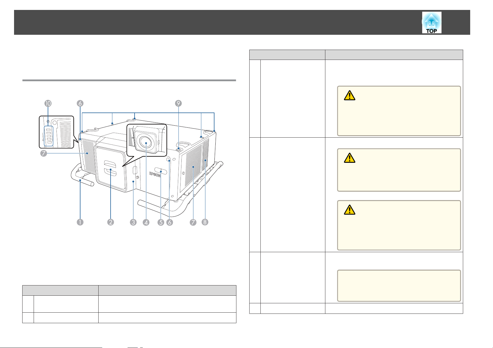
Front/Top
Name Function
Lens replacement
C
cover
Projection lens
D
Remove when attaching or removing the lens.
s "Removing and Attaching the Projector Lens Unit"
p.30
Caution
When moving the projector, do not hold the lens
replacement cover. The lens replacement cover
may be removed and the projector may fall, which
could cause an injury.
Images are projected through here.
Warning
Do not look into the lens while projecting. This
could cause damage to eyesight due to the power‐
ful light emitted.
Caution
When shifting the lens, do not put your hands near
the lens unit. Your fingers may get caught between
the lens unit and the projector, and cause an in‐
jury.
Here, the protective cap is installed.
Name Function
Handles
A
Protective cap
B
Use the handles on the left and right when carrying the
projector.
Install this when storing or transporting the projector.
Built-in camera
E
Remote receiver
F
This camera scans the image when correcting the
projected image automatically.
Attention
Exposing the camera to bright light may
cause a malfunction to occur.
Receives signals from the remote control.
Page 18
Part Names and Functions
18
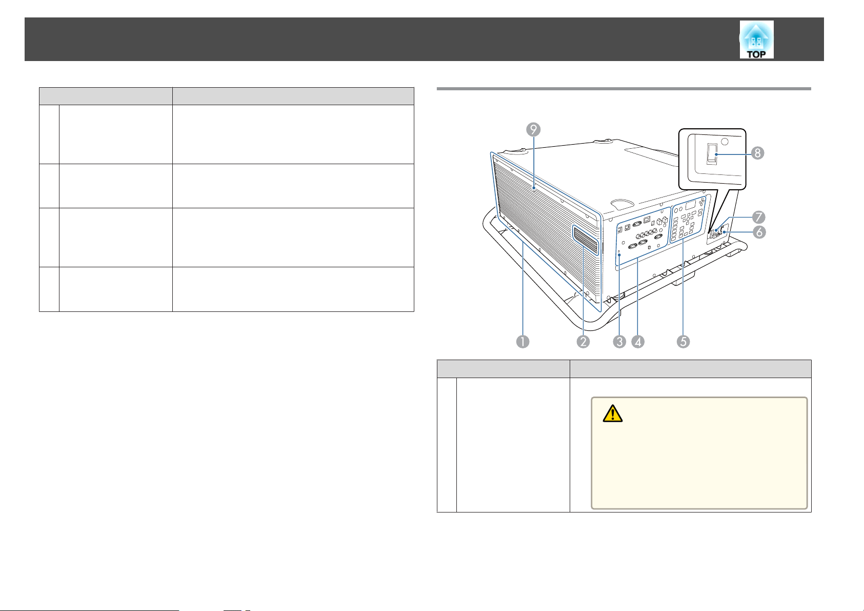
Name Function
Air intake vent
G
(air filter)
Air intake vent
H
Handle securing
I
section (6 points)
Status indicators
J
Takes in air to cool the projector internally. Be sure to
clean the air filter regularly.
s "Cleaning the Air Filter and Air Intake Vent" p.216
s "Replacing the Air Filter" p.221
Takes in air to cool the projector internally. Be sure to
clean the air intake vent regularly.
s "Cleaning the Air Filter and Air Intake Vent" p.216
Installs the optional handle.
s "Optional Accessories" p.252
You can also use this for custom installation mounts
designed by the customer.
The color of the indicators and whether they are flashing
or lit indicate the status of the projector.
s "Reading the Indicators" p.175
Rear/Side
Name Function
Air exhaust vent
A
Exhaust vent for air used to cool the projector internally.
Caution
While projecting, do not put your face or hands
near the air exhaust vent, and do not place objects
that may become warped or damaged by heat near
the air exhaust vent. Hot air from the air exhaust
vent could cause burns, warping, or accidents to
occur.
Page 19
Part Names and Functions
19
Name Function
USB-A port cover
B
(USB-A port)
Security slot
C
Connector ports
D
Control panel
E
Cable holder
F
Installs the optional wireless LAN unit.
s "Installing the Wireless LAN Unit" p.55
This is used for batch settings.
s "Batch Setup" p.165
Connects a USB flash drive to save the projector's
operation logs.
s Extended - Operation - Log Save
Destination p.147
Connects to the power port for the video receiver,
network equipment, or optical HDMI cable (for
extending). Operations for all equipment are not
guaranteed. Check that you can operate your equipment
when using this connector.
Attention
When using the projector with the cover re‐
moved, be careful not to lose the cover.
The security slot is compatible with the Microsaver
Security System manufactured by Kensington.
s "Anti-Theft Lock" p.119
s "Connector Ports" p.20
s "Control Panel" p.22
Attach this to the power cord to prevent the cord from
falling out.
Remote receiver
I
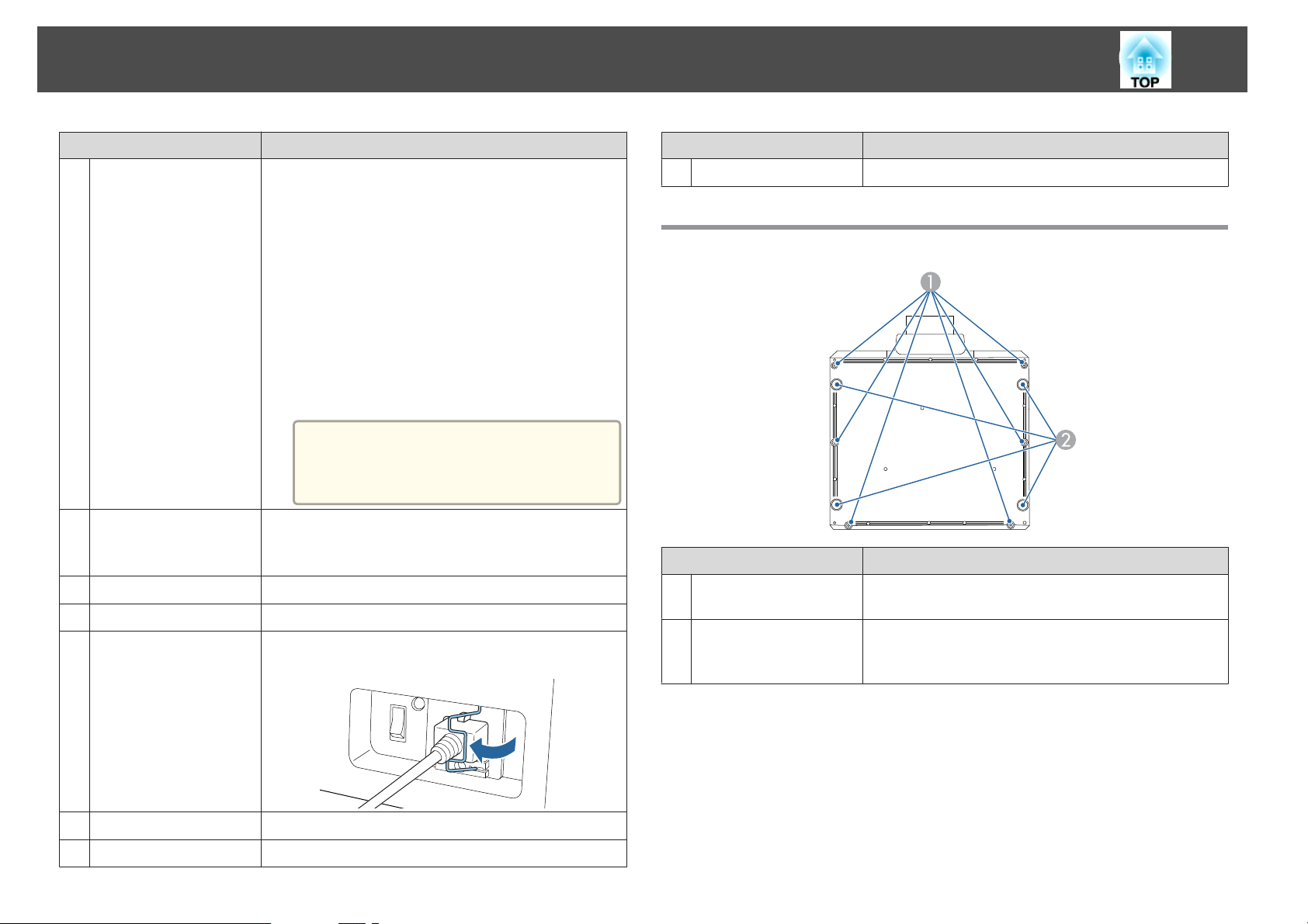
Base
Handle securing
A
section (6 points)
Feet
B
Name Function
Receives signals from the remote control.
Name Function
Installs the handle supplied.
You can remove these from the projector and attach them
to the handle. The feet are detachable. You can extend the
feet by approximately 16 mm before they detach.
Power inlet
G
Main power switch
H
Connects the power cord to the projector.
Supplies power to the projector.
Page 20
Part Names and Functions
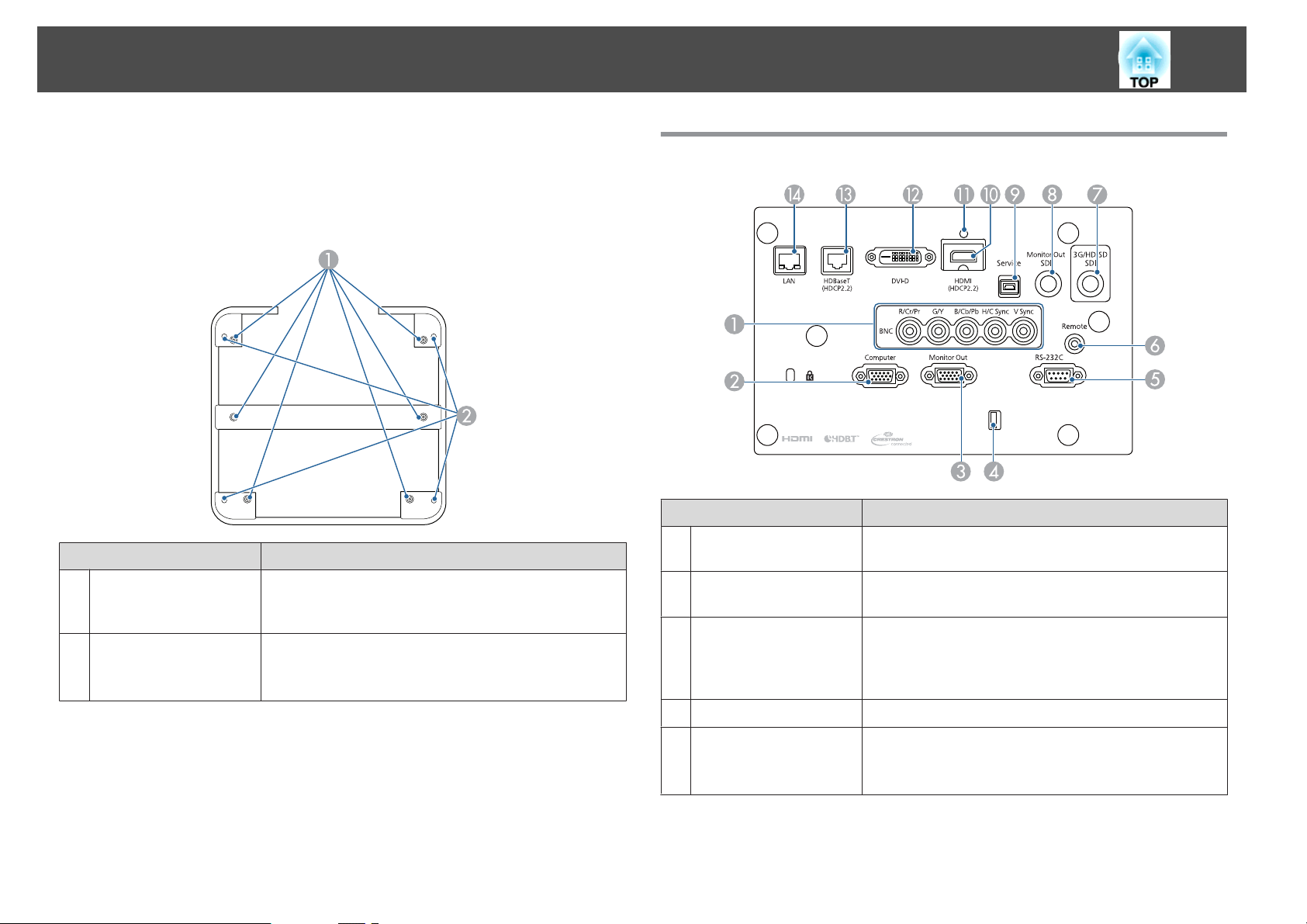
Handle
This is attached to the projector at the time of purchase.
Name Function
Screw holes for
A
securing the handle (6
points)
Screw holes for eye
B
bolts (4 points)
When attaching the handle to the projector, make sure you
secure it with the screws.
You can attach a commercially available eye bolt when
temporarily transporting the projector.
s "Cautions on Lifting" p.6
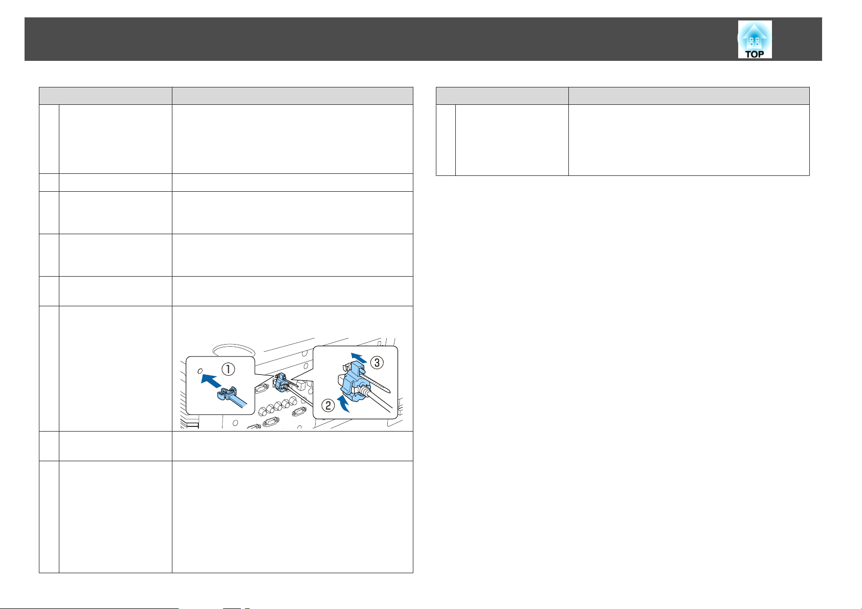
Connector Ports
Name Function
BNC port
A
Computer Port
B
Monitor Out port
C
Cable holder
D
RS-232C port
E
20
For analog RGB signals from a computer and component
video signals from other video sources.
For analog RGB signals from a computer and component
video signals from other video sources.
Outputs to an external monitor the analog signal from the
computer connected to the Computer port or the BNC
port. You cannot output signals input from other ports or
component video signals.
Run a commercially available cable tie to secure cables.
When controlling the projector from a computer, connect
it to the computer with an RS-232C cable.
s "ESC/VP21 Commands" p.239
Page 21
Part Names and Functions
21
Name Function
Remote port
F
3G/HD/SD SDI port
G
Monitor Out SDI port
H
Service port
I
HDMI port
J
Cable holder
K
Connects the optional remote control cable set and inputs
signals from the remote control. When the remote control
cable is plugged into the Remote port, the remote receiver
on the projector is disabled.
s "Optional Accessories" p.252
Inputs SDI signals from video equipment.
Connects to an external monitor, and outputs SDI signals
from video equipment being input to the 3G/HD/SD SDI
port.
This is used for batch settings. This port is for control use
and should not normally be used.
s "Batch Setup" p.165
Inputs video signals from HDMI compatible video
equipment and computers.
Insert the supplied cable clamp here to prevent the HDMI
cable from falling out.
N
Name Function
LAN port
Connects a LAN cable to connect to a network.
The projector supports Art-Net. When using Art-Net to
control the projector, set Art-Net to On from the Network
menu.
s Network - Others - Art-Net p.160
DVI-D port
L
HDBaseT port
M
Inputs the computer DVI-D signals.
Connects a LAN cable to the optional HDBaseT
Transmitter.
s "Connecting an HDBaseT Transmitter" p.54
s "Optional Accessories" p.252
The projector supports Art-Net. When using Art-Net to
control the projector, set Art-Net to On from the Network
menu.
s Network - Others - Art-Net p.160
Page 22
Part Names and Functions
22
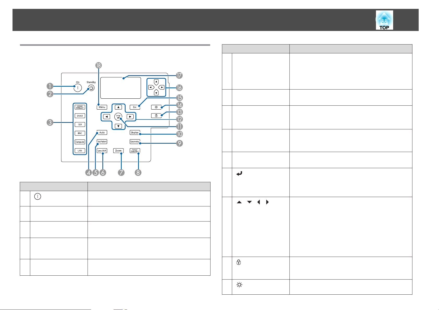
Control Panel
Name Function
A
[ ] button
[t] button
B
Change input buttons
C
[Auto] button
D
[Test Pattern] button
E
Starts projection when the main power switch is on and
the projector is in standby mode.
Places the projector in standby mode when the main
power switch is on and it is projecting.
Changes to images from each input port.
s "Switching to the Target Image" p.61
If pressed while projecting analog RGB signals from the
Computer port or the BNC port, you can automatically
optimize Tracking, Sync., and Position.
Displays a test pattern.
s "Displaying the Test Pattern" p.36
Name Function
[Lens Shift] button
F
[Zoom] button
G
[Focus/Distortion]
H
button
[Geometry] button
I
[Shutter] button
J
K
[ ] button
L
[ ][ ][ ][ ]
buttons
M
[ ] button
Press to adjust the lens shift.
s "Adjusting the Position of the Projected Image (Lens
Shift Adjustment)" p.37
If pressed for more than three seconds, the lens position
moves to the home position.
Press to adjust the zoom.
s "Adjusting the Image Size" p.39
Press this to adjust the focus or correct distortion.
s "Correcting the Focus" p.40
s "Correcting Distortion (Image Warping)" p.41
Corrects distortion in the projected image.
s "Correcting Distortion in the Projected Image"
p.62
Press to turn the image on or off temporarily.
s "Hiding the Image Temporarily (Shutter)" p.106
When the Configuration menu or the Help screen is
displayed, it accepts and enters the current selection and
moves to the next level.
s "Configuration Menu Operations" p.137
Press to adjust focus, zoom, distortion, and lens shift.
s "Adjusting the Position of the Projected Image
(Lens Shift Adjustment)" p.37
s "Adjusting the Image Size" p.39
"Correcting the Focus" p.40
s
If pressed when the Configuration menu or the Help
screen is displayed, menu items and setting values are
selected.
s "Configuration Menu Operations" p.137
Displays the Control Panel Lock screen allowing you to
make settings to lock the control panel buttons.
s "Restricting Operation" p.117
N
[ ] button
Press to turn on or off the buttons on the control panel and
the LCD display.
Page 23
Part Names and Functions
23
Name Function
[Esc] button
O
P
[ ][ ][ ][ ]
buttons
LCD display
Q
[Menu] button
R
Stops the current function.
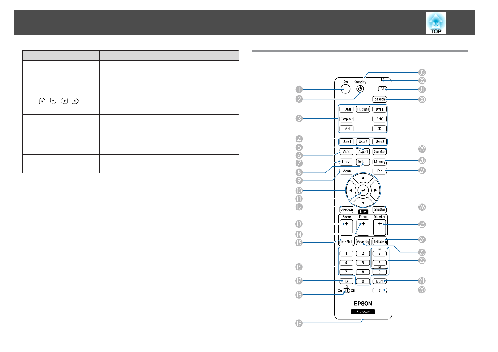
Remote Control
If pressed when the Configuration menu is displayed, it
returns to the previous menu level.
s "Configuration Menu Operations" p.137
Select menu items and settings displayed on the LCD
display.
Displays the projector's status by character information.
s "Understanding the Status Information" p.182
Displays the static IP address setting menu.
s "Setting a Static IP Address Using the LCD Display"
p.132
Displays and closes the Configuration menu.
s "Configuration Menu Operations" p.137
Page 24
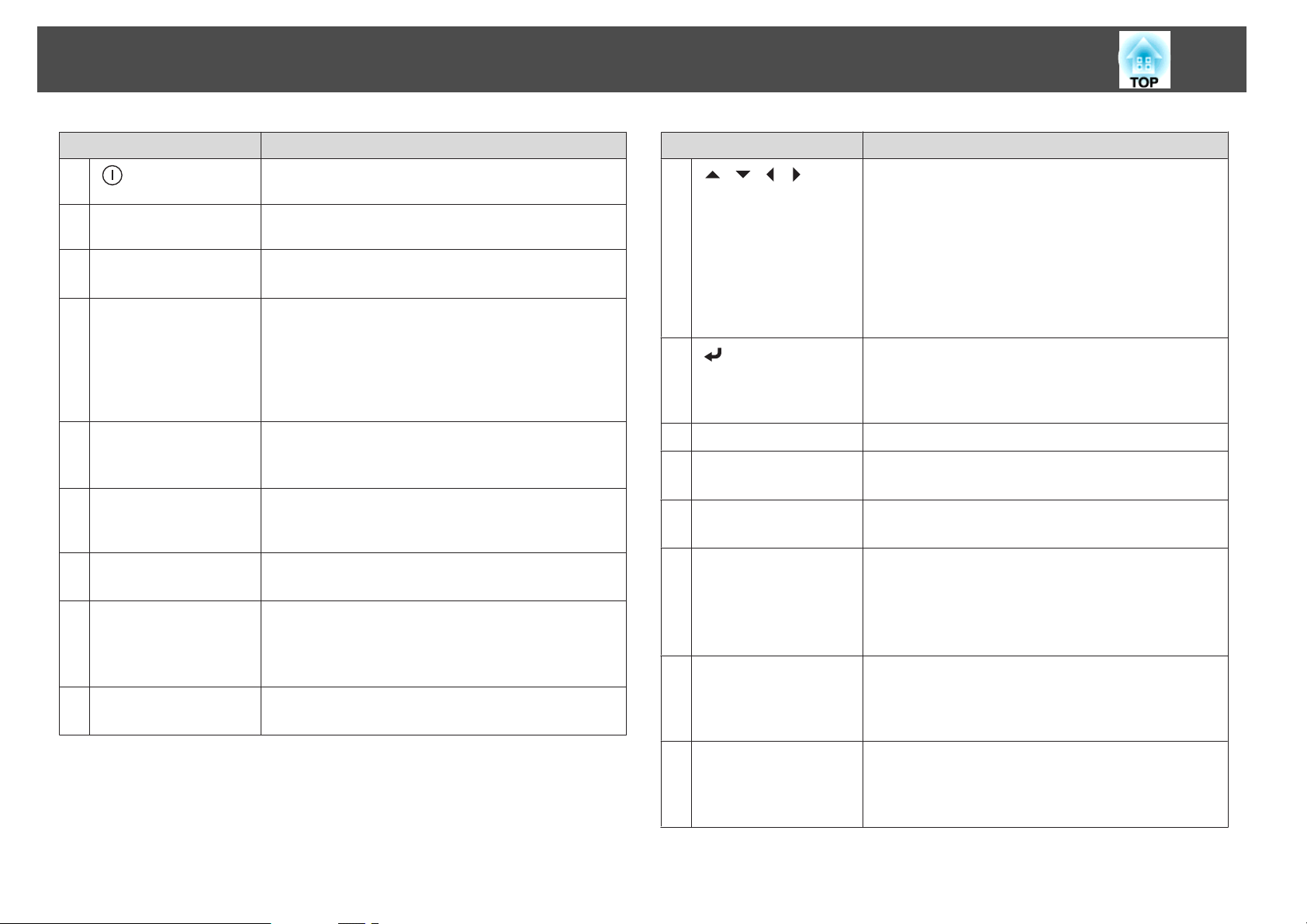
Part Names and Functions
24
Name Function
A
[ ] button
[t] button
B
Change input buttons
C
[User1] button
D
[User2] button
[User3] button
[Aspect] button
E
[Auto] button
F
[Freeze] button
G
[Default] button
H
[Menu] button
I
Starts projection when the main power switch is on and
the projector is in standby mode.
Places the projector in standby mode when the main
power switch is on and it is projecting.
Changes to images from each input port.
s "Switching to the Target Image" p.61
Select any frequently used item from the Configuration
menu items, and assign it to any of these buttons. By
pressing the button, the assigned menu item selection/
adjustment screen is displayed, allowing you to make onetouch settings/adjustments.
s "Settings Menu" p.145
Each time the button is pressed, the aspect mode changes.
s "Changing the Aspect Ratio of the Projected Image"
p.78
If pressed while projecting analog RGB signals from the
Computer port or the BNC port, you can automatically
optimize Tracking, Sync., and Position.
Images are paused or unpaused.
s "Freezing the Image (Freeze)" p.107
Enabled when [Default]: Reset is displayed on the
configuration menu guide. The settings being adjusted are
returned to their default values.
s "Configuration Menu Operations" p.137
Displays and closes the Configuration menu.
s "Configuration Menu Operations" p.137
Name Function
J
[ ][ ][ ][ ]
buttons
K
[ ] button
[On-Screen] button
L
[Zoom] button
M
[Focus] button
N
[Lens Shift] button
O
Numeric buttons
P
Press to adjust focus, zoom, distortion, and lens shift.
s "Adjusting the Position of the Projected Image
(Lens Shift Adjustment)" p.37
s "Adjusting the Image Size" p.39
s "Correcting the Focus" p.40
If pressed when the Configuration menu or the Help
screen is displayed, menu items and setting values are
selected.
s "Configuration Menu Operations" p.137
When the Configuration menu or the Help screen is
displayed, it accepts and enters the current selection and
moves to the next level.
s "Configuration Menu Operations" p.137
Shows or hides the Configuration.
Press to adjust the zoom.
s "Adjusting the Image Size" p.39
Press to adjust the focus.
s "Correcting the Focus" p.40
Press to adjust the lens shift.
s "Adjusting the Position of the Projected Image (Lens
Shift Adjustment)" p.37
If pressed for more than three seconds, the lens position
moves to the home position.
Enter the Password.
s "Setting Password Protection" p.115
Use this button to enter numbers in Network settings
from the Configuration menu.
[ID] button
Q
Hold down this button and press the numeric buttons to
select the ID for the projector you want to operate using
the remote control.
s "ID Settings" p.43
Page 25
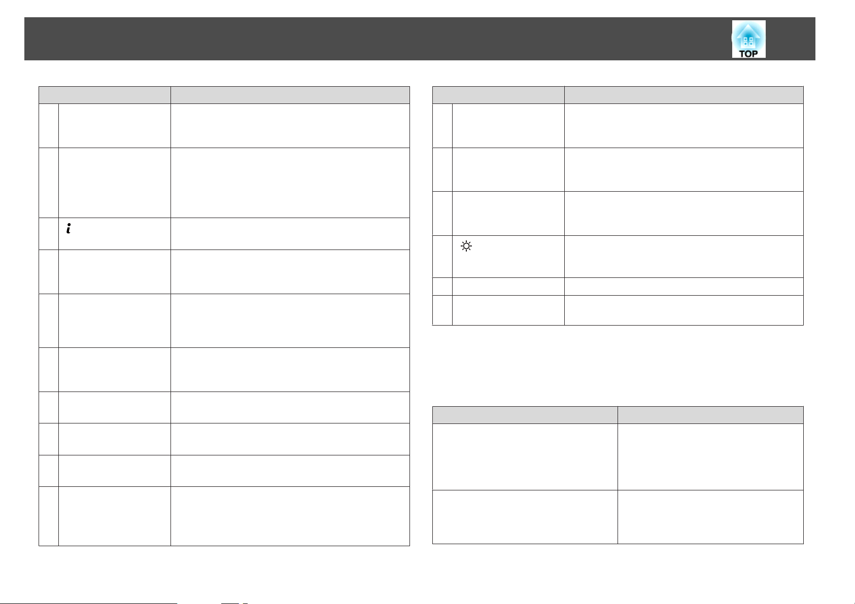
Part Names and Functions
25
Name Function
[ID] switch
R
Remote port
S
T
[ ] button
[Num] button
U
[[] []] buttons
V
[Geometry] button
W
[Test Pattern] button
X
[Distortion] button
Y
[Shutter] button
Z
[Esc] button
a
Use this switch to enable (On)/disable (Off) ID settings for
the remote control.
s "ID Settings" p.43
Connects the optional remote control cable set and
outputs signals from the remote control.
s "Optional Accessories" p.252
When the remote control cable is plugged into this remote
port, the remote control light-emitting is disabled.
Displays the Info menu from the Configuration menu.
s "Info Menu (Display Only)" p.161
Hold down this button and press the numeric buttons to
enter passwords and numbers.
s "Setting Password Protection" p.115
Changes the test pattern displayed.
Moves to the previous or next image file when
projecting images from a computer connected via a
network.
Corrects distortion in the projected image.
s "Correcting Distortion in the Projected Image"
p.62
Displays a test pattern.
s "Displaying the Test Pattern" p.36
Press to correct distortion.
s "Correcting Distortion (Image Warping)" p.41
Press to turn the image on or off temporarily.
s "Hiding the Image Temporarily (Shutter)" p.106
Stops the current function.
If pressed when the Configuration menu is displayed, it
moves to the previous level.
s "Configuration Menu Operations" p.137
Name Function
[Memory] button
b
[Color Mode] button
c
[Search] button
d
e
[ ] button
Indicator
f
Remote control light-
g
emitting area
Performs operations and makes settings for the memory
function.
s "Memory Function" p.109
Each time the button is pressed, the Color Mode changes.
s "Selecting the Projection Quality (Selecting Color
Mode)" p.74
Changes to the next input source that is sending an image.
s "Automatically Detecting Input Signals and Changing
the Projected Image (Source Search)" p.60
Illuminates the buttons on the remote control for
approximately 15 seconds. This is useful when using the
remote control in the dark.
A light is emitted when outputting remote control signals.
Outputs remote control signals.
Handy remote control operations
You can perform the following operations by simply pressing one of the
buttons on the remote control.
Operation Set
Reverse the projected image vertically.
(Switch the Projection between Front and
Front/Ceiling)
s "Changing the direction of the image
(projection mode)" p.34
Selecting the password security settings.
s "Managing Users (Password
Protection)" p.115
Hold down the [Shutter] button for more
than five seconds.
Hold down the [Freeze] button for more
than five seconds. The Password Protection
screen is displayed, and you can select
various settings.
Page 26
Part Names and Functions
26
Operation Set
Locking or unlocking some of the operation
of the buttons on the remote control.
s "Remote control button lock" p.118
Initializing the settings for the Remote
Receiver in the Configuration menu.
(Enables all Remote receivers for this
projector.)
Displaying frequently used Configuration
menu items.
Hold down the [
seconds.
Hold down the [Menu] button for more than
15 seconds.
Press the [User1], [User2], or [User3]
button. You can set the menu item you want
to assign to each button in User Button.
s Settings - User Button p.145
The following items can be assigned.
Light Source Mode, Multi-Projection,
Resolution, Display the QR Code, Image
Enhancement, Frame Interpolation,
Screen Matching, Color Calibration, Help,
Split Screen
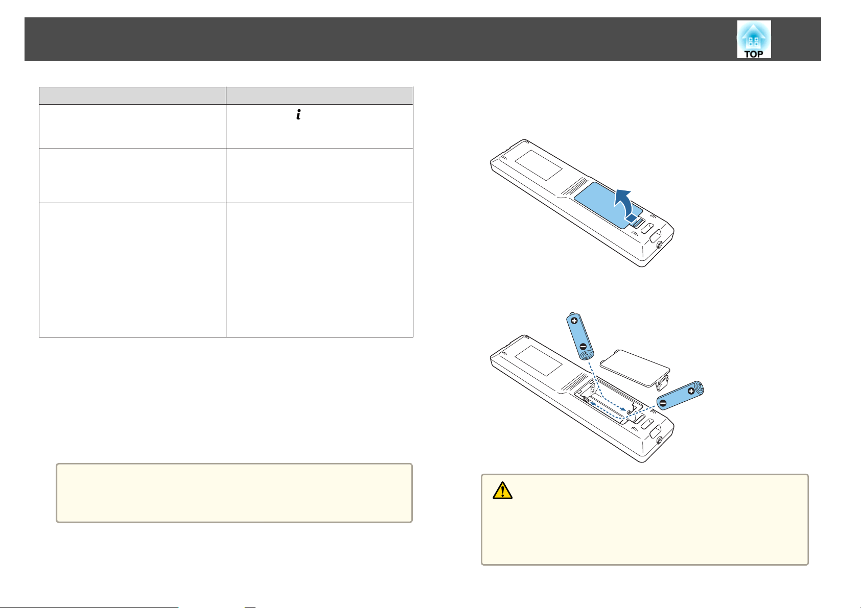
Replacing the remote control batteries
] button for more than five
a
b
Remove the battery cover.
While pushing the battery compartment cover catch, lift the cover
up.
Replace the old batteries with new batteries.
If delays in the responsiveness of the remote control occur or if it does not
operate after it has been used for some time, it probably means that the
batteries are becoming flat. When this happens, replace them with new
batteries. Have two AA size alkaline or manganese batteries ready. You
cannot use other batteries except for the AA size alkaline or manganese.
Attention
Make sure you read the following manual before handling the batteries.
s Safety Instructions
Caution
Check the positions of the (+) and (–) marks inside the battery holder to
ensure the batteries are inserted the correct way.
If the batteries are not used correctly, they could explode or leak causing
a fire, injury, or damage to the product.
Page 27
Part Names and Functions
27
c
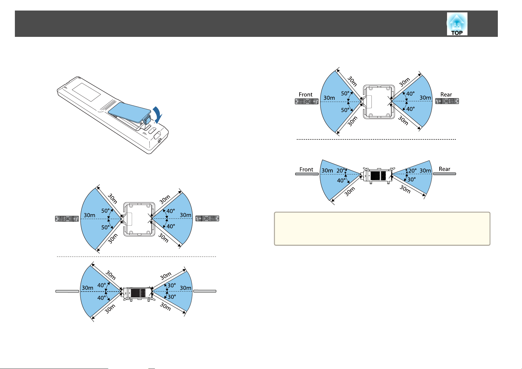
Remote control operating range
Replace the battery cover.
Press the battery compartment cover until it clicks into place.
When the handle is installed at the top
To restrict reception of the operation signals from the remote control,
a
set Remote Receiver.
s Settings - Remote Receiver p.145
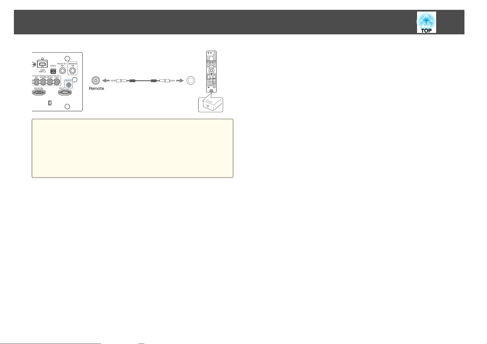
Connecting a cable to the remote control
You can make operations securely with the optional Remote control cable
set when you use multiple units of this projector in the same place or when
there are obstacles around the remote receiver.
s
"Optional Accessories" p.252
Page 28
Part Names and Functions
When the remote control cable is plugged into the Remote port, the
a
remote receiver on the projector is disabled.
When the remote control cable is plugged into the remote port of
the remote control, the remote control indicator does not turn on.
You can also connect the optional HDBaseT transmitter and remote
control with the cable to control the projector.
s "Connecting an HDBaseT Transmitter" p.54
28
Page 29

Preparing the Projector
This chapter explains how to install the projector and connect projection sources.
Page 30
Installing the Projector
Removing and Attaching the Projector Lens Unit
Warning
Make sure you disconnect the power cord from the projector before removing
or attaching the lens unit to the projector. Otherwise, it could cause an electric
shock.
Attaching
30
Attention
Do not attach the lens unit when the projector's lens insertion section is
facing up. Dust or dirt could enter the projector.
Try not to touch the lens section with your hand or fingers. If fingerprints or
oils are left on the surface of the lens, projection quality deteriorates.
The projector supports lens with the following model numbers.
a
a
ELPLR05/ELPLU05/ELPLW07/ELPLM12/ELPLM13/ELPLM14/
ELPLL09/ELPLL10
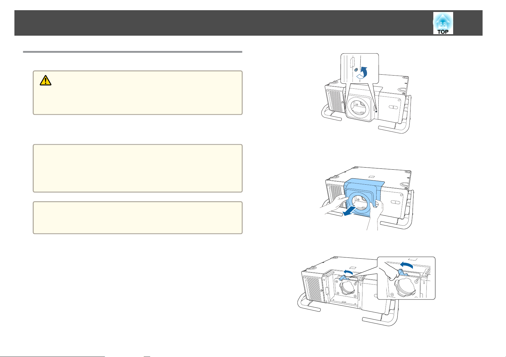
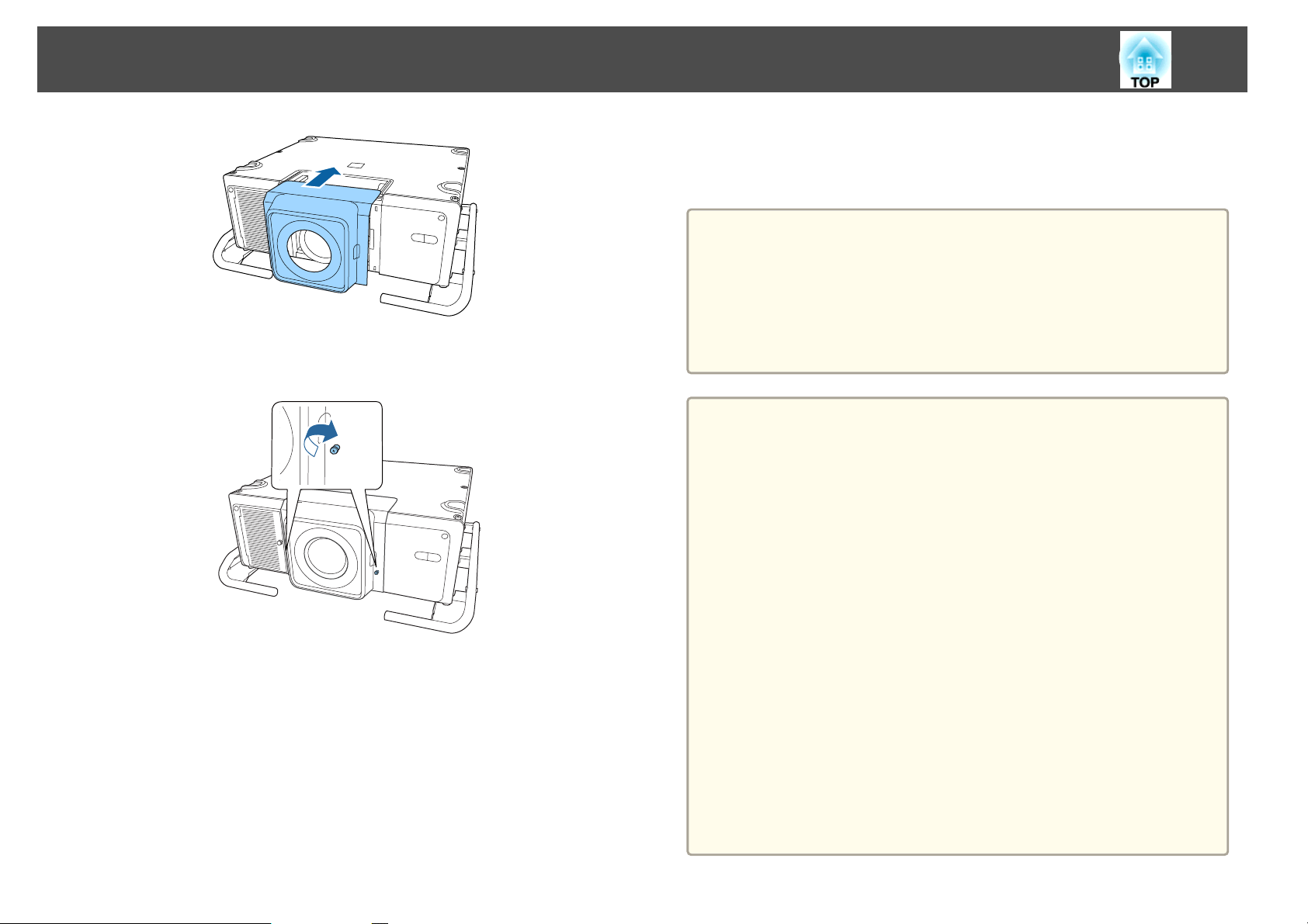
Loosen the lens cover fixing screws.
Turn the screws by hand.
b
c
While pressing the tabs on both sides of the lens replacement
cover, pull it towards you to remove it.
Turn the lock lever counterclockwise.
Page 31
Installing the Projector
31
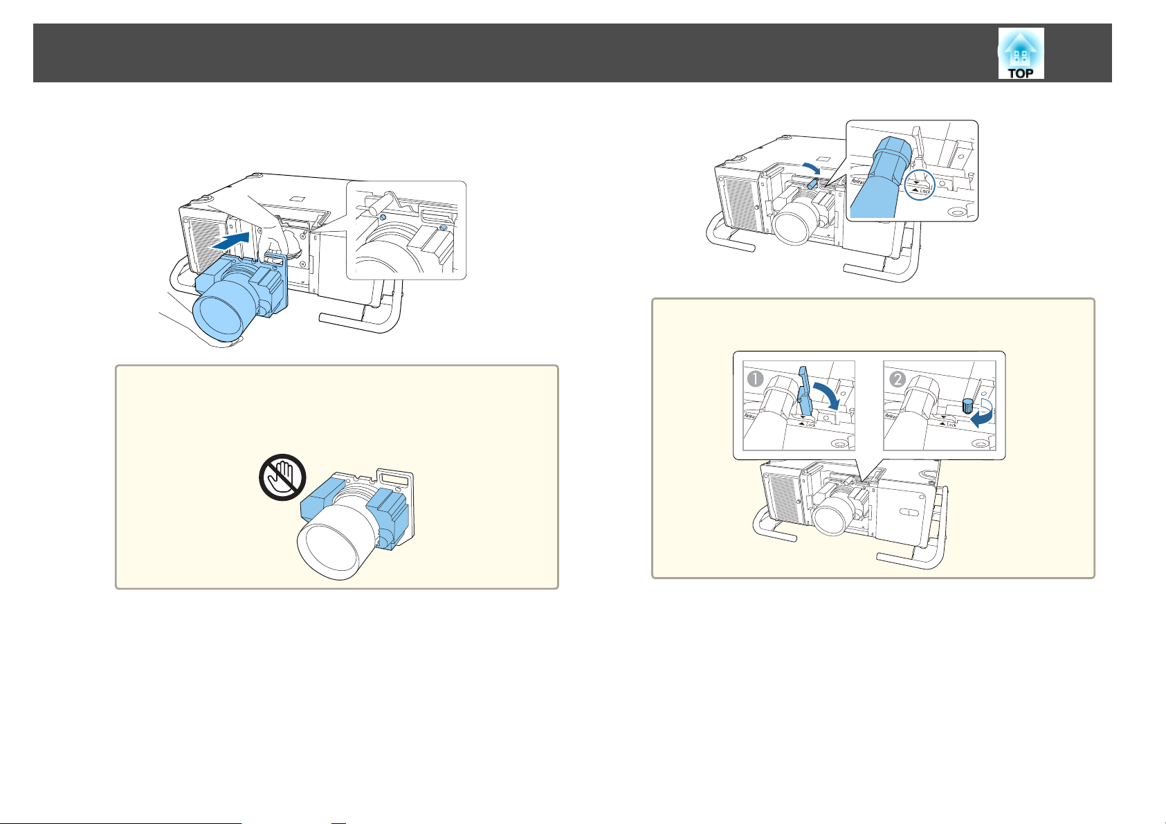
d
Insert the lens unit straight so that the protruding points on the
lens fit through the holes (2 points) at the top of the lens unit.
Attention
When attaching the lens unit, do not touch the motor covers shown in
the following illustration (2 points). Otherwise, the lens unit may
malfunction.
a
To further secure the lever, tighten the screw. You can turn the
screw by hand.
e
While holding the lens unit firmly, hold the lock lever and turn it
clockwise to lock the lens unit.
Check that the lens cannot be detached.
f
Attach the lens replacement cover.
Page 32
Installing the Projector
Tighten the lens cover fixing screws.
g
32
Lens calibration takes up to about 3 minutes until it is complete. When the
calibration is finished the lens returns to the position before calibration was
performed.
Attention
If the message "Lens Calibration failed." is displayed, remove the lens unit and
then reinstall it. If the message continues to be displayed, stop using the
projector, remove the power plug from the electrical outlet, and contact your
local dealer or the nearest address provided in the Epson Projector Contact
List.
s Epson Projector Contact List
If the projector cannot determine the model number of your lens,
a
you cannot perform lens calibration.
Use one of the following methods to perform lens calibration.
- Hold down the [Default] button on the remote control for at least three
seconds.
- Configuration Menu
s Extended - Operation - Lens Calibration p.147
Lens Calibration
After replacing the lens unit, calibrate the lens so that the projector can
correctly acquire the lens position and adjustment range.
After attaching a different lens unit from the previous one, a message is
displayed when the projector is turned on.
Select Yes to calibrate the lens.
If no message is displayed after attaching the lens unit, perform lens
calibration from the Configuration menu.
If you do not calibrate the lens, the following functions may not
operate correctly.
- Lens Shift
- Memory (Lens Position)
- Zoom
-Focus
- Distortion
You can check the lens calibration history from the following menu.
Extended - Operation - Lens Calibration - History p.147
s
Page 33
Installing the Projector
33
Removing
Caution
Wait for a while after turning off the projector before removing the lens unit
(approximately 30 mins.). Touching the lens unit immediately after projecting
or turning off may cause burns.
Attention
If you have used lens shift to move the lens position, move the lens to the
home position and then replace the lens unit.
s "Adjusting the Position of the Projected Image (Lens Shift Adjustment)"
p.37
The projector uses a laser as the light source. As a safety measure, the
a
light source turns off when the lens is removed. Attach the lens, and
then press the [
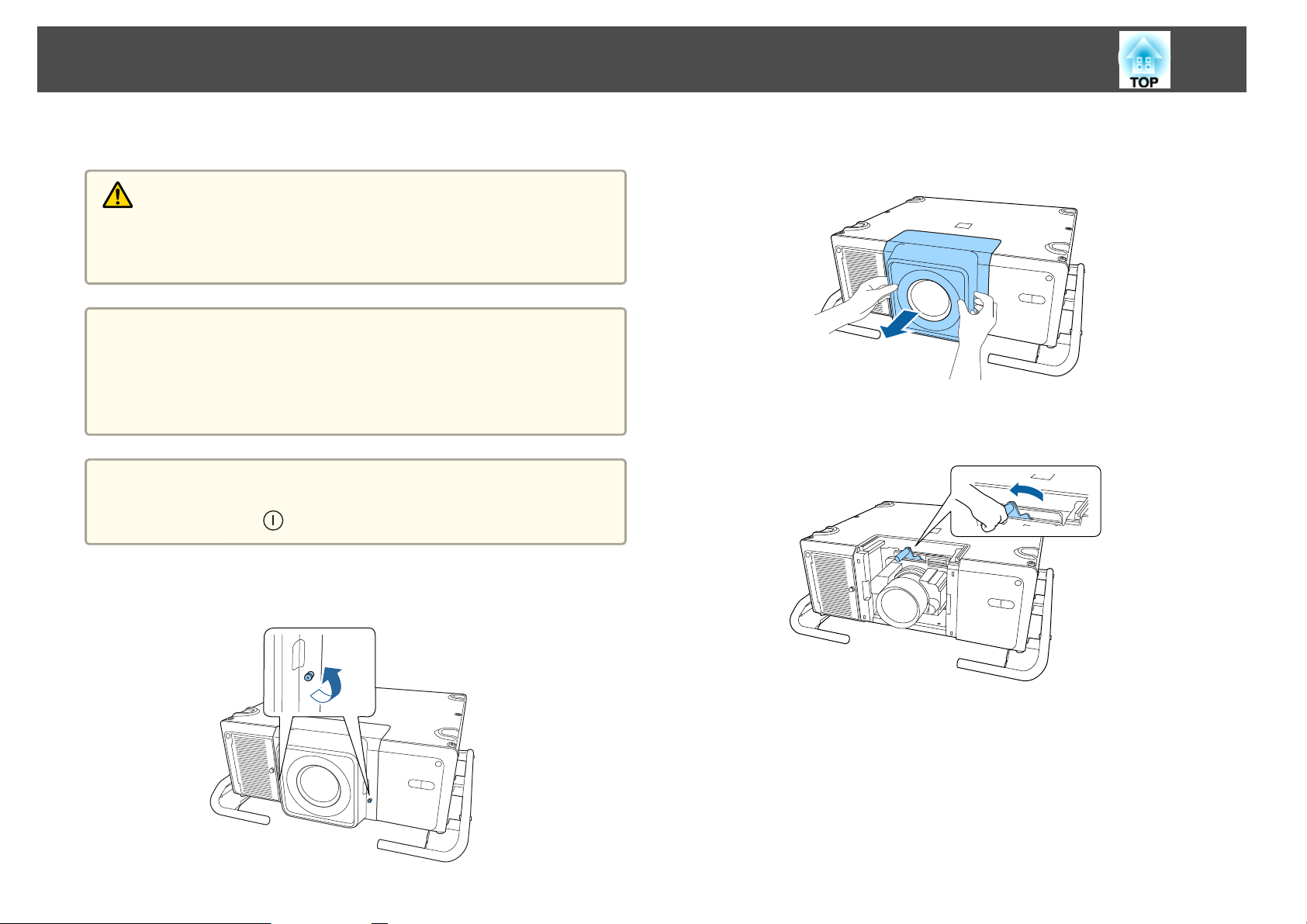
Loosen the lens cover fixing screws.
] button to turn it back on.
a
Turn the screws by hand.
b
c
While pressing the tabs on both sides of the lens replacement
cover, pull it towards you to remove it.
While holding the lens unit firmly, turn the lock lever
counterclockwise until it is unlocked.
Page 34
Installing the Projector
34
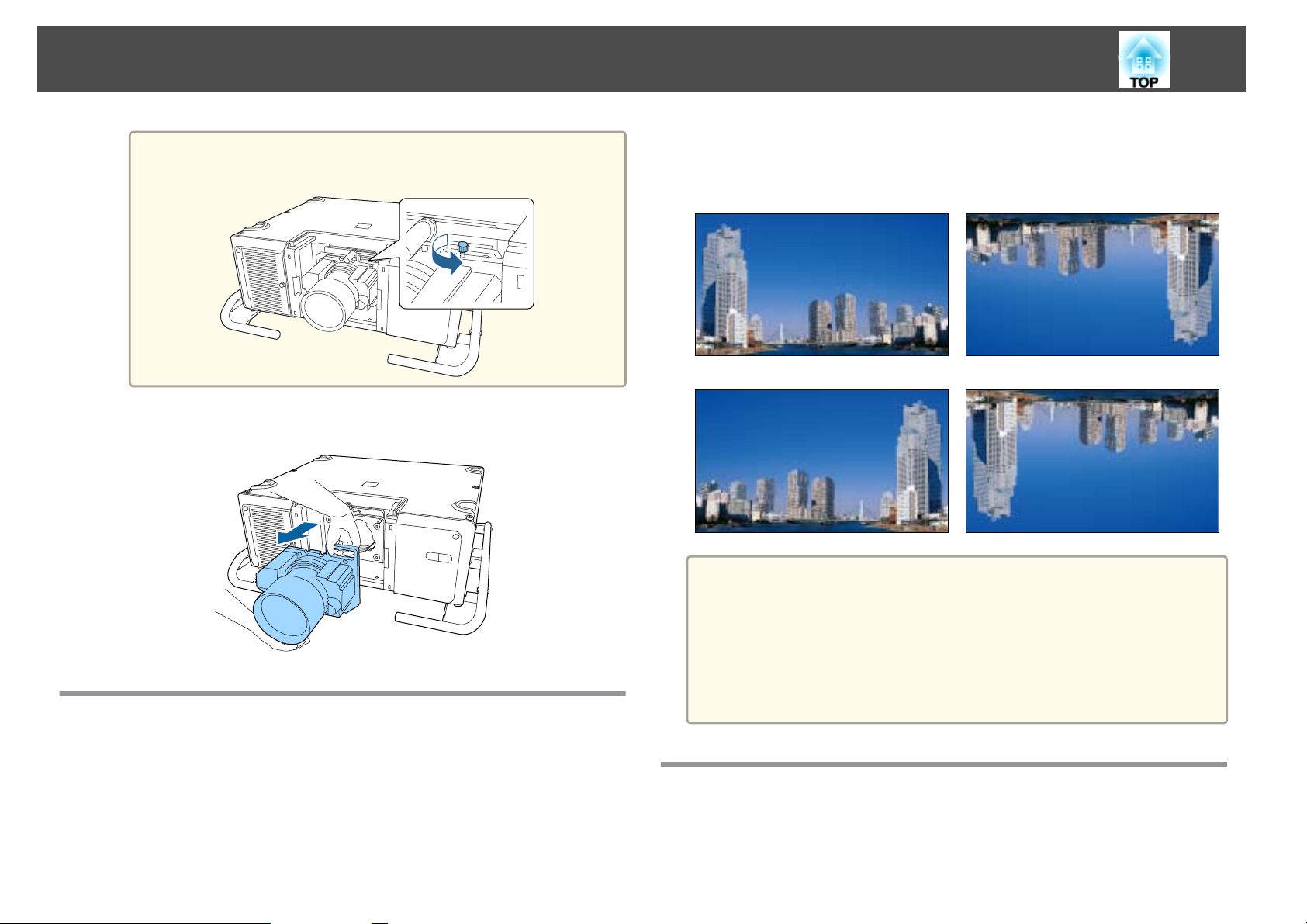
If the lever has been secured with the screw, loosen the screw
a
Pull the lens unit straight out.
first.
d
Installation Settings
When Front is the standard, the image directions for each projection mode
are as follows.
Front (default) Front/Ceiling
Rear Rear/Ceiling
You can change the setting as follows by pressing down the [Shutter]
a
button on the remote control for about five seconds.
FrontWFront/Ceiling
RearWRear/Ceiling
To rotate the menu display, set OSD Rotation in the Configuration
menu.
s Extended - Display - OSD Rotation p.147
Changing the direction of the image (projection mode)
You can change the direction of the image using Projection mode from the
Configuration menu.
s
Extended - Projection p.147
Screen Settings
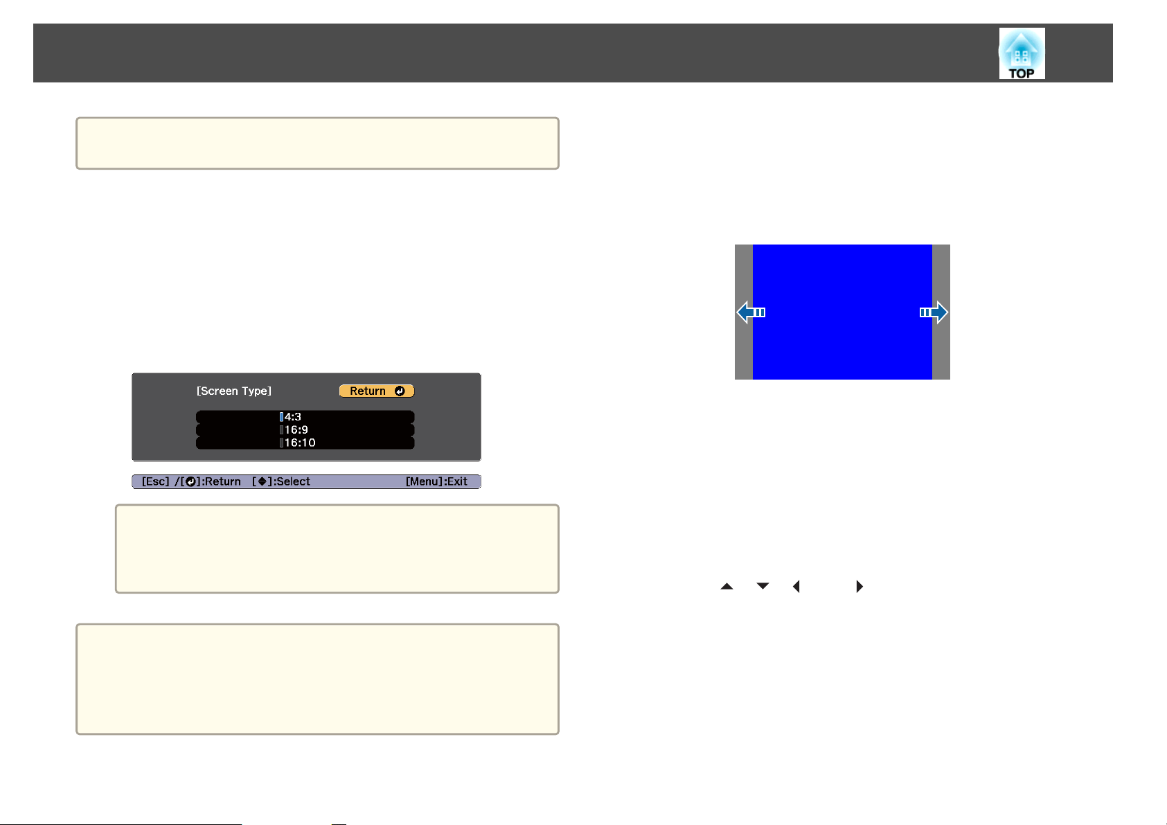
Set the Screen Type according to the aspect ratio of the screen being used.
The area where the image is displayed matches the shape of the screen.
Page 35
Installing the Projector
35
a
a
b
c
d
The setting for the Screen Type at the time of purchase is 16:10.
Press the [Menu] button while projecting.
s
"Configuration Menu Operations" p.137
Select Display from Extended.
Select Screen Type from Screen.
Select the screen's aspect ratio.
The shape of the background test pattern changes depending
a
on the setting.
The EDID changes depending on the setting. When a
message is displayed, select Yes.
Adjusting the position of the image on the projected screen
You can adjust the position of the image if there are margins between the
edge of the image and the projected screen frame due to the Screen Type
setting.
Example: When the Screen Type is set to 4:3
You can move the image to the left and right.
a
Press the [Menu] button while projecting.
s
"Configuration Menu Operations" p.137
Select Display from Extended.
b
c
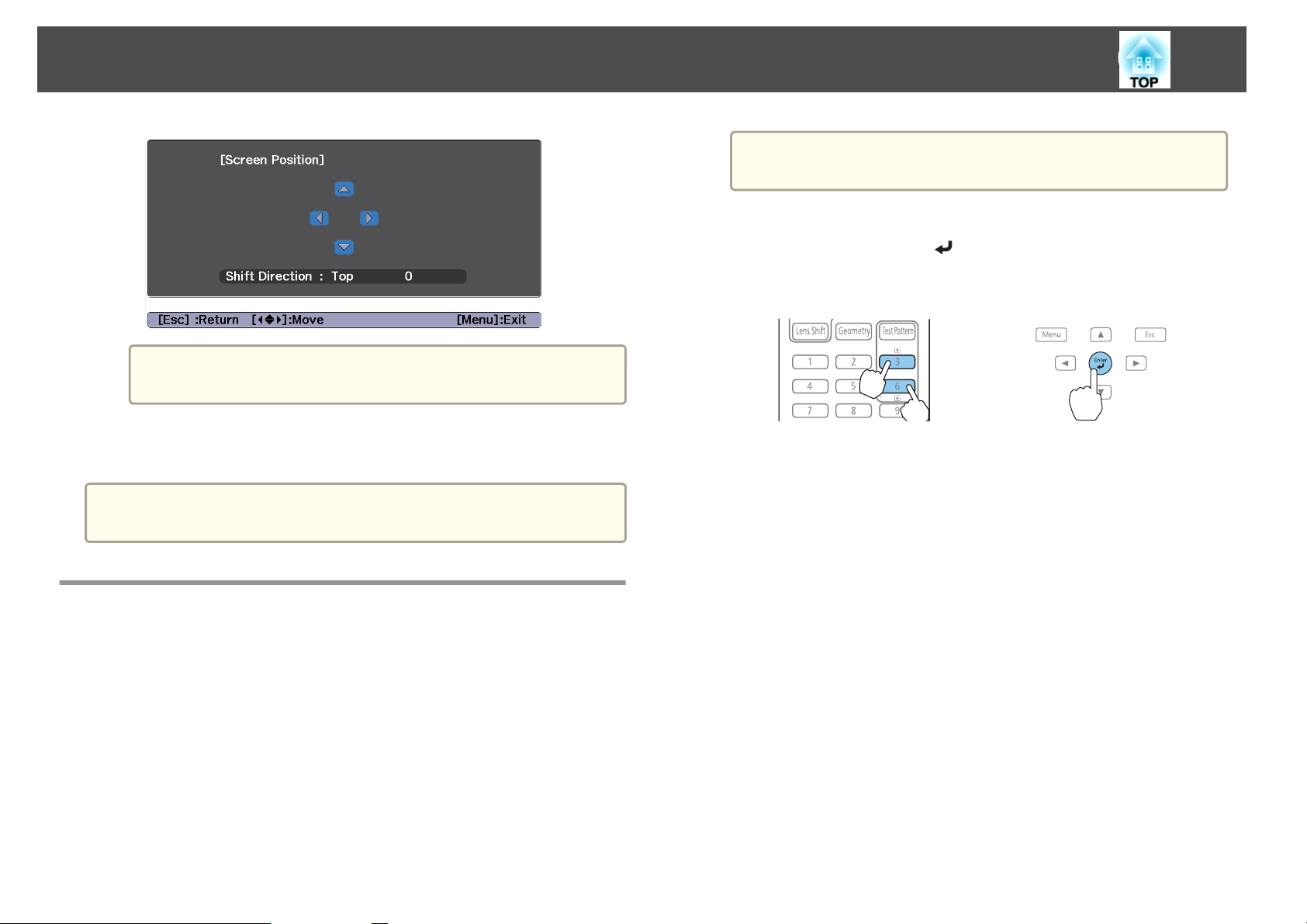
Select Screen Position from Screen.
d
Use the [ ], [ ], [ ], and [ ] buttons to adjust the position of
the image.
a
When you change the Screen Type, adjust the aspect ratio for the
projected image as well.
s "Changing the Aspect Ratio of the Projected Image" p.78
The Message Broadcasting function for Epson Projector Management
does not support this function.
Page 36
Installing the Projector
a
36
Press the [Test Pattern] button again to display the screen for
selecting the type of test pattern.
You can check the current display position by using the
a
Press the [Menu] button to finish making settings.
background test pattern.
e
When the Screen Type is set to 16:10, the Screen Position cannot be
a
Displaying the Test Pattern
A test pattern can be displayed to adjust the projection status without
connecting video equipment.
adjusted.
b
You can switch test patterns by pressing the [[] []] buttons on
the remote control or the [
test pattern is displayed.
Using the remote control Using the control panel
] button on the control panel while a
The shape of a test pattern is according to the setting of Screen Type. Set
Screen Type first.
s
"Screen Settings" p.34
a
Press the [Test Pattern] button of the remote control or the control
panel while projecting.
Page 37
Installing the Projector
37
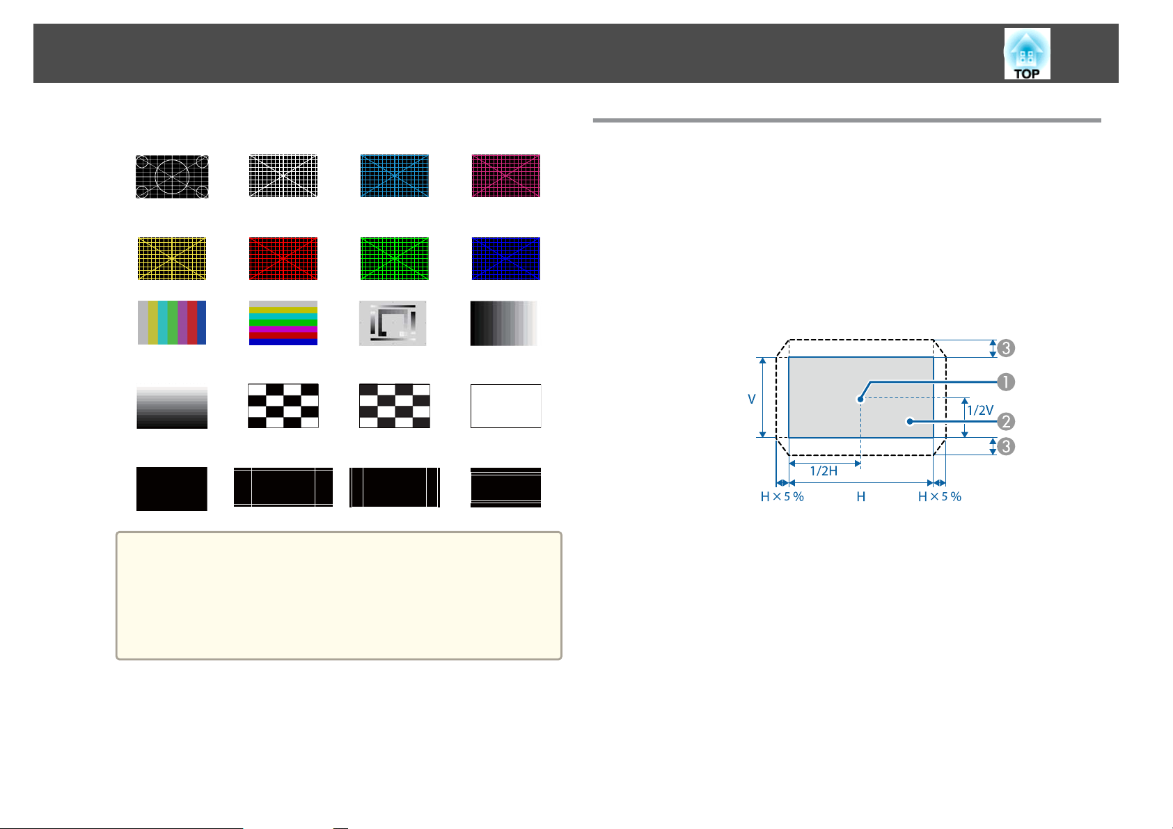
Standard Cross-hatching Cross-hatchingCCross-hatching
M
Cross-hatchingYCross-hatchingRCross-hatchingGCross-hatching
B
Color Bars V Color Bars H Grayscale Gray Bars V
Gray Bars H Checkerboard1Checkerboard
2
Black 16:10 Aspect
Frame
16:9 Aspect
Frame
White
4:3 Aspect
Frame
Adjusting the Position of the Projected Image (Lens Shift Adjustment)
The lens can be shifted to adjust the position of the projected image, for
example, when the projector cannot be installed directly in front of the
screen.
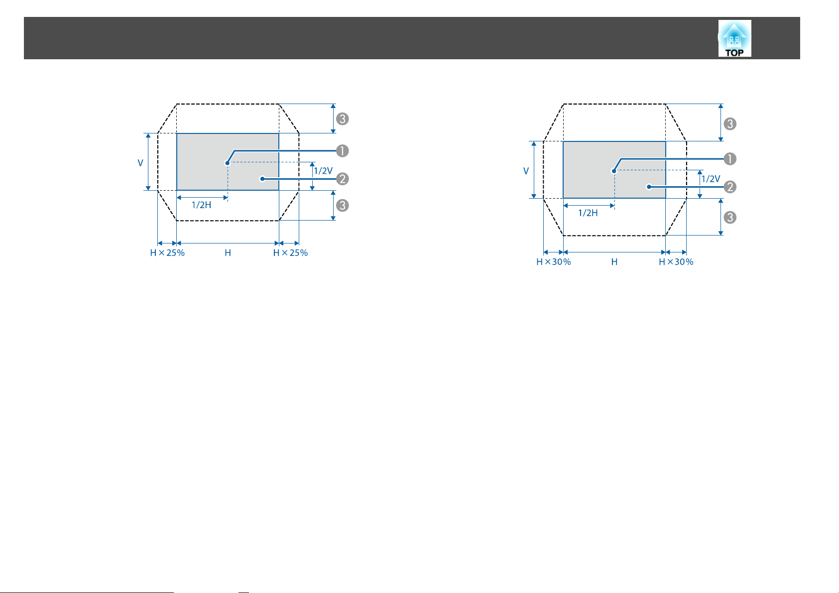
The ranges within which the image can be moved are shown below. The
position of the projected image cannot be moved to both the horizontal and
vertical maximum values.
When using the ELPLR05
c
To set menu items that cannot be set while the test pattern is
a
Press the [Esc] button to close the test pattern.
being displayed or to fine-tune the projected image, project an
image from the connected device.
You can also select a test pattern from the Configuration
menu.
s Settings - Test Pattern p.145
Center of lens
A
Projected image when the lens position is moved to the home
B
position
Maximum motion range: V x 15%
C
* When the horizontal direction is at the maximum value, the image
cannot be moved up or down.
*
Page 38
Installing the Projector
38
When using ELPLU05/ELPLL09/ELPLL10
Center of lens
A
Projected image when the lens position is moved to the home
B
position
Maximum motion range: V x 55%
C
* When the horizontal direction is at the maximum value, the image
cannot be moved up or down.
*
When using the ELPLW07/ELPLM12/ELPLM13/ELPLM14
Center of lens
A
Projected image when the lens position is moved to the home
B
position
Maximum motion range: V x 65%
C
* When performing screen matching: V x 60% (ELPLM13)
* When the horizontal direction is at the maximum value, the image
cannot be moved up or down.
*
Page 39
Installing the Projector
39
a
a
When adjusting the image height with the vertical lens shift, adjust
by moving the image from the bottom to the top. If it is adjusted
from the top to the bottom, the image position may move down
slightly after adjusting.
We recommend setting the focus, zoom, and lens shift at least 20
minutes after you start the projection, because images are not stable
right after turning on the projector.
The image will be clearest when the lens position is moved to the
home position.
If you hold down the [Lens Shift] button on the remote control or
the control panel for at least three seconds, the lens position moves
to the home position.
If you set A/V Output to Always On, you can move the lens
position to the home position even if the projector is in standby
mode.
Extended - A/V Settings - A/V Output p.147
s
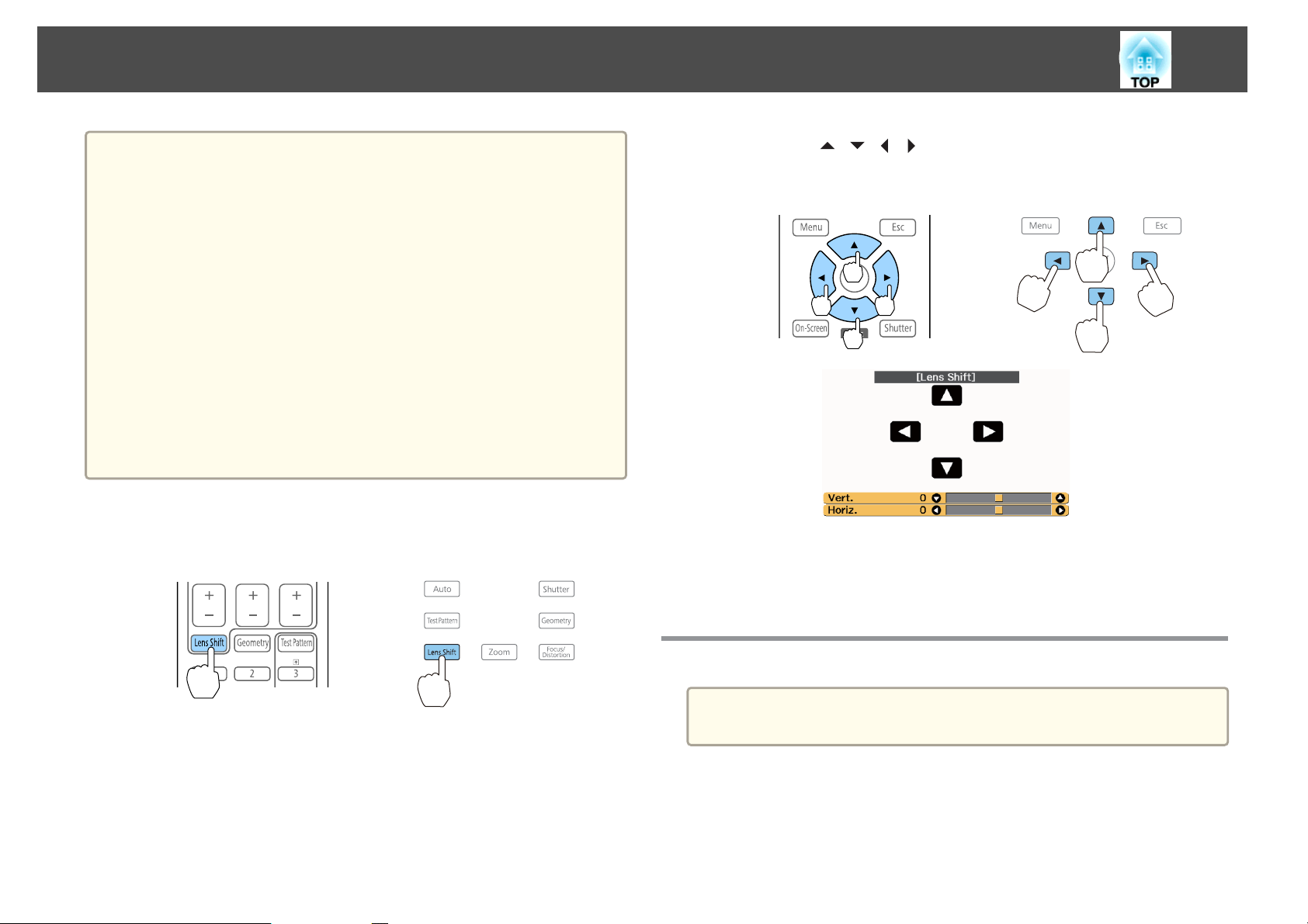
Press the [Lens Shift] button on the remote control or the control
panel.
Using the remote control Using the control panel
b
c
Press the [ ][ ][ ][ ] buttons to adjust the position of the
projected image.
Using the remote control Using the control panel
The displayed screen may differ depending on your lens.
Press the [Esc] button to finish the adjustment.
Adjusting the Image Size
This is not available for the ELPLR05.
a
Page 40
Installing the Projector
40
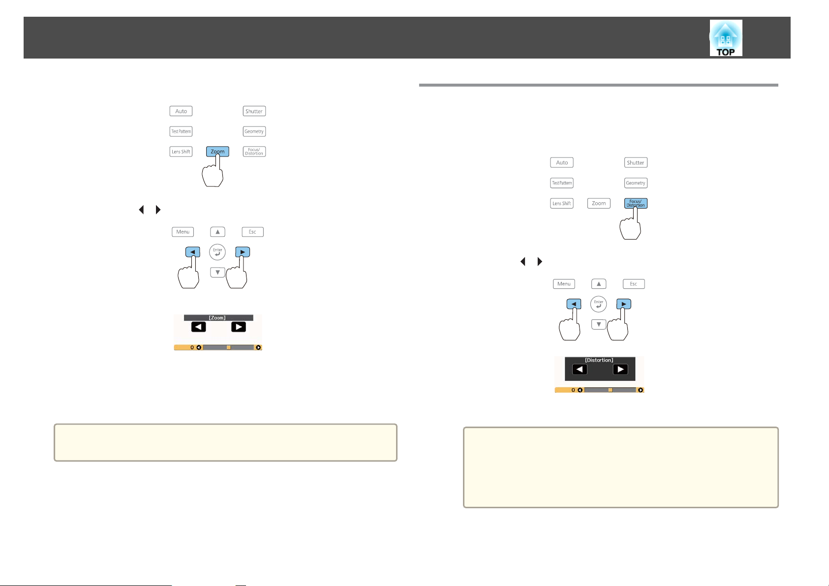
a
b
Press the [Zoom] button on the control panel.
Press the [ ][ ] buttons to adjust.
The displayed screen may differ depending on your lens.
Correcting the Focus
a
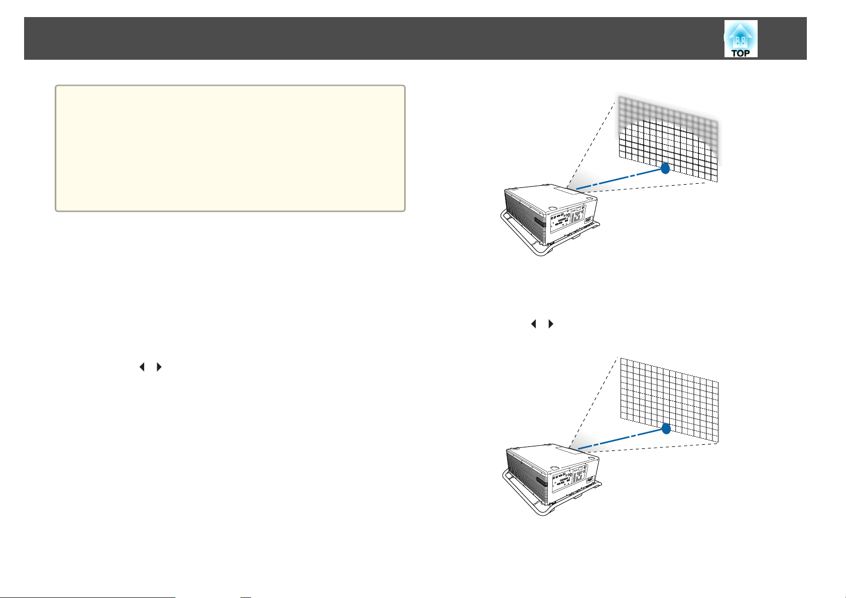
Press the [Focus/Distortion] button on the control panel.
Press repeatedly until the focus adjustment screen is displayed.
Press the [ ][ ] buttons to adjust.
b
c
a
Press the [Esc] button to finish the adjustment.
You can also use the [Zoom] buttons ([+] and [-]) on the remote
control to adjust the size of the image.
c
The displayed screen may differ depending on your lens.
When using the following lens, a message prompting you to
a
Press the [Esc] button to finish the adjustment.
adjust the distortion (image warping) is displayed. After
adjusting the focus, adjust the distortion.
ELPLR05, ELPLU05
s "Correcting Distortion (Image Warping)" p.41
Page 41
Installing the Projector
You can also use the [Focus] buttons ([+] and [-]) on the remote
a
Correcting Distortion (Image Warping)
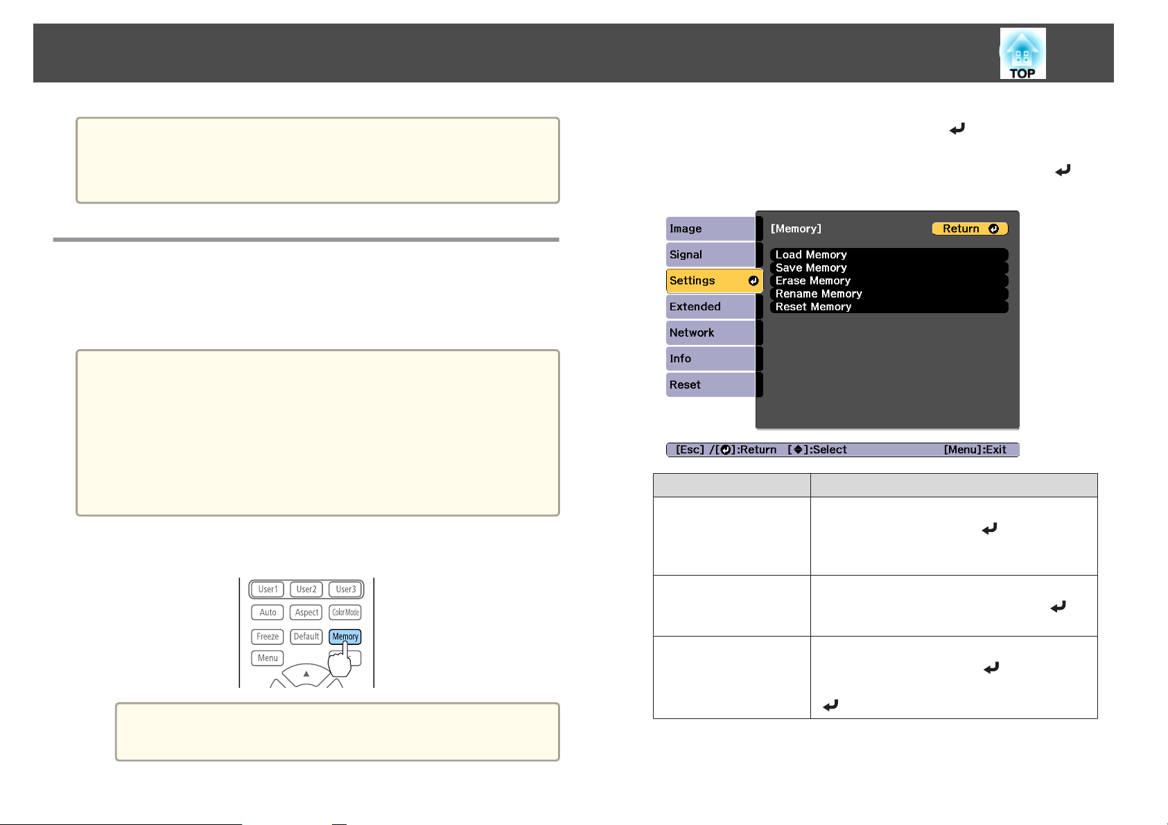
When using the ELPLR05 or ELPLU05 and focusing at the center of the
screen, the surrounding image may warp and be out of focus. Follow the
steps below to correct the warping.
control to adjust the focus.
When projecting from several projectors and there is a difference in
brightness, we recommend displaying the grayscale test pattern and
adjusting the focus.
If the focus is not correct even after adjusting the focus, hold down
the [Default] button on the remote control for about three seconds
to perform lens calibration. When lens calibration is complete, adjust
the focus again.
c
41
Press the [Focus/Distortion] button on the control panel again.
Press repeatedly until the distortion adjustment screen is displayed.
a
b
Press the [Focus/Distortion] button on the control panel.
Press repeatedly until the focus adjustment screen is displayed.
Press the [ ][ ] buttons to focus the image around the center of
the lens.
d
Press the [ ][ ] button to adjust the focus of the surrounding
area.
If the center is out of focus after adjusting the surrounding image,
repeat steps 1 to 2.
Page 42
Installing the Projector
42
You can also adjust distortion in images using the remote control.
a
After adjusting the focus at the center of the lens using the [Focus]
buttons ([+] and [-]), use the [Distortion] buttons ([+] and [-]) to
adjust the surrounding image.
Registering and Loading Lens Adjustment Values
You can register a lens position whose lens shift, zoom, focus, and
distortion was adjusted in memory, and load it when necessary. You can
register up to 10 values.
If you did not calibrate your lens, a message is displayed when you
a
save a memory. Select Yes to calibrate the lens.
The lens position when a memory is loaded may not completely
match the lens position when the memory was saved.
If there is a large discrepancy between the lens position when a
memory is loaded and the lens position when the memory was
saved, calibrate the lens.
s Extended - Operation - Lens Calibration p.147
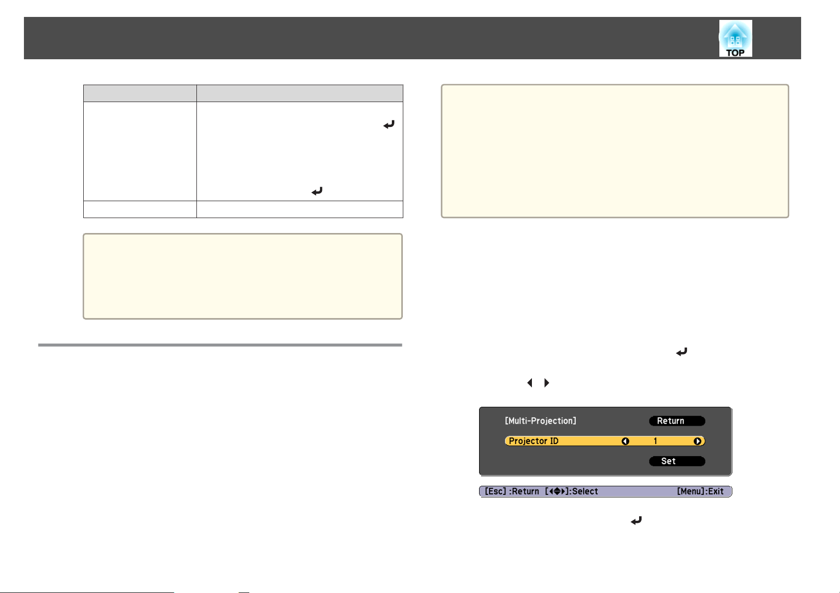
Press the [Memory] button while projecting.
a
b
c
Select Lens Position, and then press the [ ] button.
Select the function you want to perform, then press the [ ]
button.
Function Explanation
Load Memory
Loads the saved memory. When you select a
memory name and press the [
is automatically adjusted according to the settings
of the selected memory.
] button, the lens
a
You can also operate from the Configuration menu.
s Settings - Memory p.145
Save Memory
Erase Memory
Registers current settings in the memory. When
you select a memory name and press the [
button, the settings are saved.
Erases the registered memory. When you select a
memory name and press the [
message is displayed. Select Yes, and then press the
[
] button to erase the selected memory.
] button, a
]
Page 43
Installing the Projector
43
Function Explanation
Rename Memory
Reset Memory
If the mark on the left of the memory name is turned blue, it
a
means the memory has already been registered. When you
select a registered memory, a message is displayed asking you to
confirm that you want to overwrite the memory. If you select
Yes, the previous settings are deleted and the current settings
are registered.
Changes the memory name. Select the memory
name you want to change, and then press the [
button. Enter the memory name using the soft
keyboard.
s "Soft keyboard operations" p.153
When you have finished, move the cursor over
Finish, and then press the [
Resets the name and settings of a saved memory.
] button.
ID Settings
When an ID is set for the projector and the remote control, you can use
the remote control to operate only the projector with a matching ID. This
is very useful when managing multiple projectors. You can set up to 30
IDs.
a
]
Set the projector ID
a
b
c
d
Operation using the remote control is possible only for projectors
that are within the operating range of the remote control.
s "Remote control operating range" p.27
IDs are ignored when the projector ID is set to Off or the remote
control ID is set to 0.
If you use Epson Web Control, you can operate a specific projector
from a mobile device.
"Changing Settings Using a Web Browser (Epson Web Control)"
s
p.230
Press the [Menu] button while projecting.
s
"Configuration Menu Operations" p.137
Select Multi-Projection from Extended.
Select Projector ID, and then press the [ ] button.
Press the [ ][ ] buttons to select an ID number.
e
f
Select Set, and then press the [ ] button.
Press the [Menu] button to close the Configuration menu.
Page 44
Installing the Projector
44
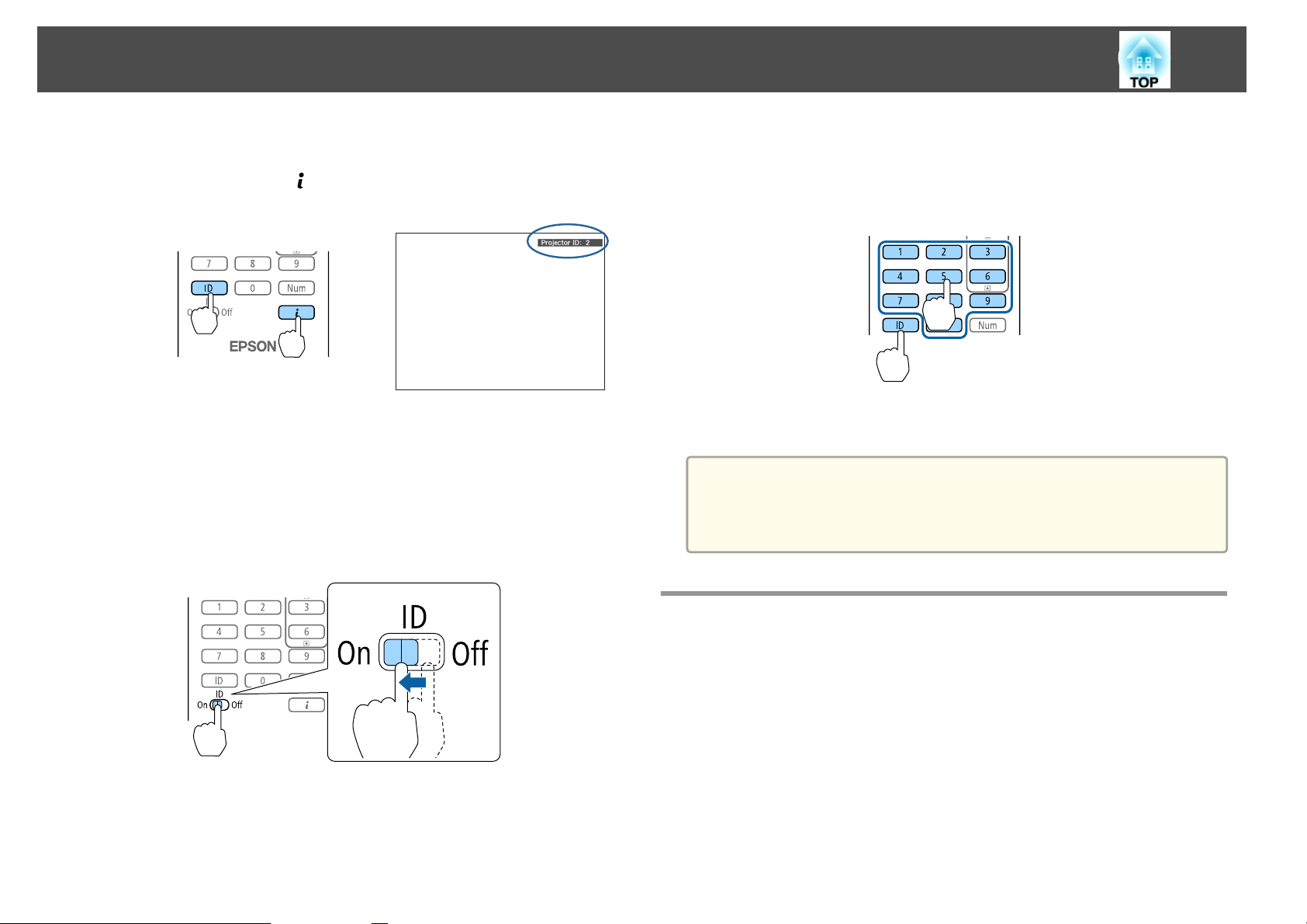
Checking the projector ID
During projection, press the [ ] button while holding down the [ID] button
on the remote control.
When you press the buttons, the current Projector ID is displayed on the
projection screen. It disappears in about three seconds.
Setting the remote control ID
Set the remote control [ID] switch to On.
a
b
Once this setting has been made, the projector that can be operated by the
remote control is limited.
While holding the [ID] button, press a number button to select a
number to match the ID of the projector you want to operate.
s
"Checking the projector ID" p.44
Enter a two digit number (Example: 01 when the ID is 1).
The remote control ID setting is saved in the remote control. Even if
a
the remote control batteries are removed to replace them and so on,
the stored ID setting is retained. However, if the batteries are left out
for a long time, it is reset to the default value (ID0).
Setting the Time
You can set the time for the projector. The set time is used for the schedule
function.
s
"Scheduling Function" p.111
Page 45
Installing the Projector
45
a
a
b
c
d
When you turn on the projector for the first time, the message "Do
you want to set the time?" is displayed. When you select Yes, the
screen from step 4 is displayed.
When Schedule Protection is set to On in Password Protection,
settings related to the date and time cannot be changed. You can
make changes after setting Schedule Protection to Off.
"Managing Users (Password Protection)" p.115
s
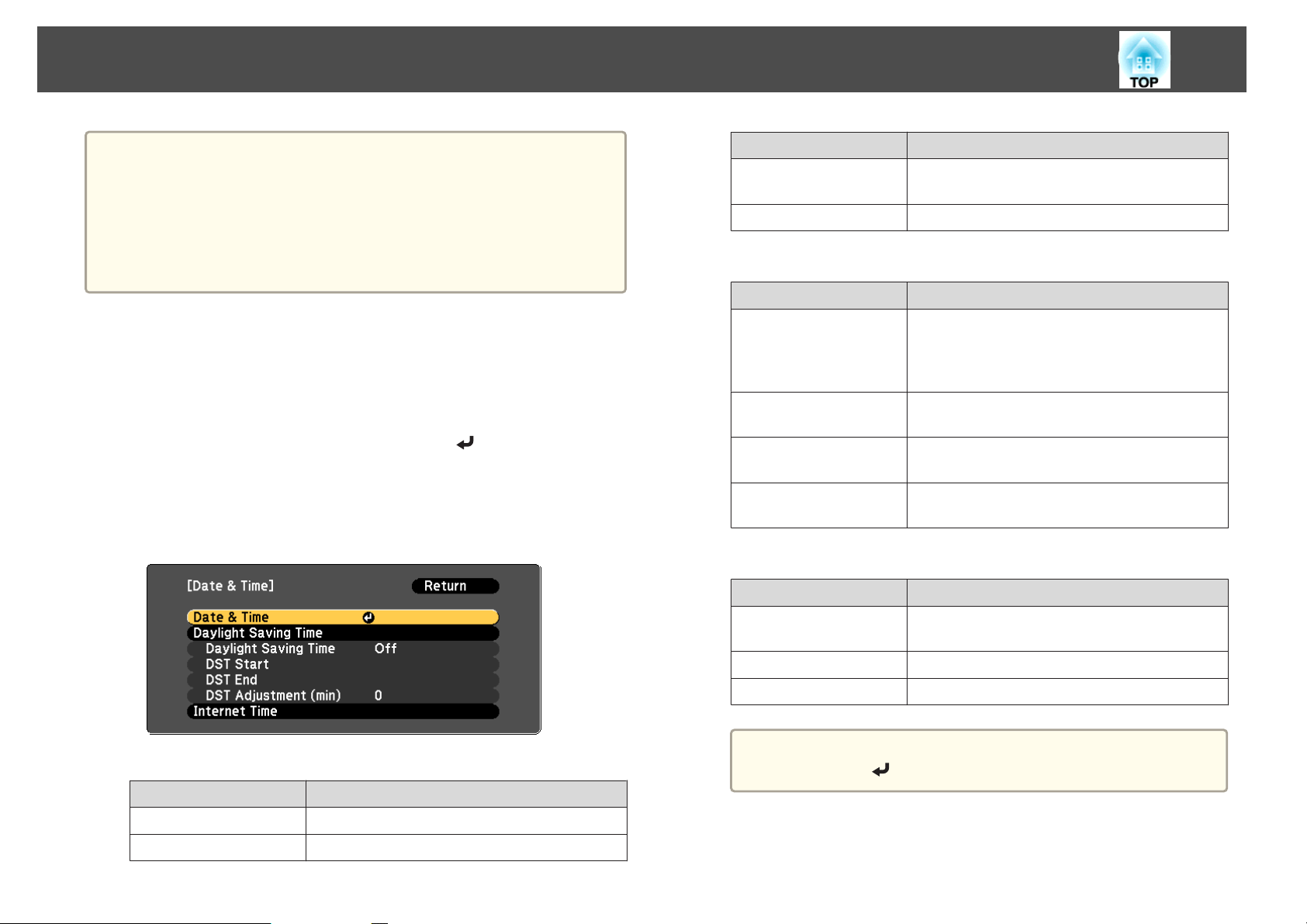
Press the [Menu] button while projecting.
s
"Configuration Menu Operations" p.137
Select Operation from Extended.
Select Date & Time, and then press the [ ] button.
Make settings for the date and time.
Use the soft keyboard to enter the date and time.
s
"Soft keyboard operations" p.153
Submenu Function
Time Difference (UTC)
Settings
Daylight Saving Time
Submenu Function
Daylight Saving Time
DST Start
DST End
Settings
Internet Time
Submenu Function
Internet Time
Set the time difference from Coordinated
Universal Time.
The settings made in Date & Time are applied.
Set whether or not (On/Off) to activate the
daylight saving time. DST Adjustment (min)
adjusts the time difference between the standard
time and daylight saving time.
Set the date and time to start the daylight saving
time.
Set the date and time to end the daylight saving
time.
The settings made in Daylight Saving Time are
applied.
Set to On to update the time automatically through
an Internet time server.
Date & Time
Submenu Function
Date
Time
Set today's date.
Set the current time.
e
Internet Time Server
Settings
When changing settings, make sure you select Set, and then
a
Press the [Menu] button to finish making settings.
press the [
Input the IP address for an Internet time server.
The settings made in Internet Time are applied.
] button.
Page 46
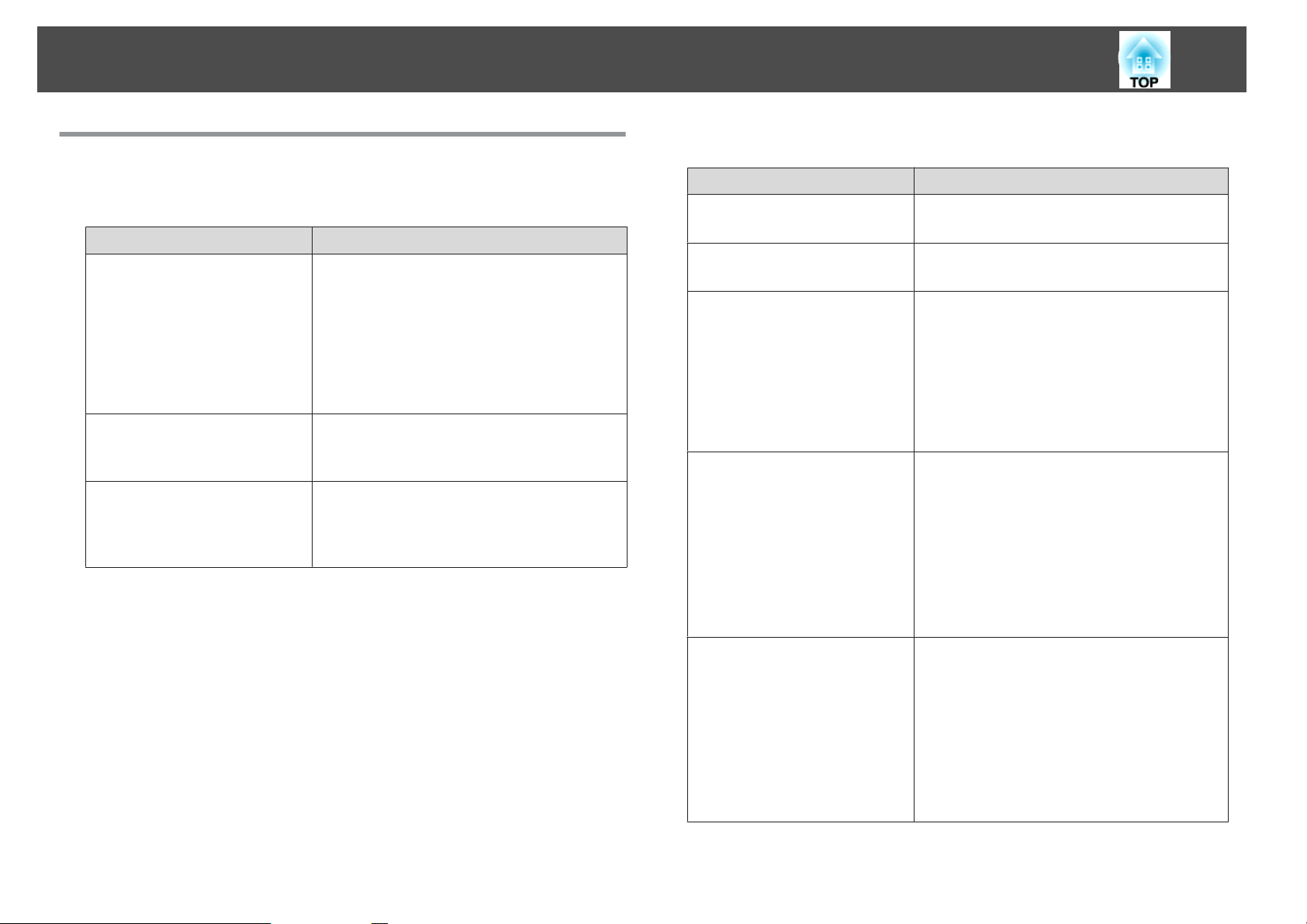
Installing the Projector
46
Other Settings
Settings related to basic operations
Purpose Setting Methods
To start/stop projection by turning
on/off the main power switch or
plugging in or unplugging the
power plug of the projector.
To disable buzzer beeps generated
when the projector is powered on/
off.
Turn off the power by pressing the
[t] button once.
When Direct Power On is set to On, the
projector can start projecting when power is
supplied. (Default value: Off)
s Extended - Operation - Direct Power
On p.147
The projector can be powered off directly by the
breaker because it supports the direct shutdown
function.
Set Beep to Off. (Default value: On)
s Extended - Operation -Advanced - Beep
p.147
Set Standby Confirmation to Off. (Default value:
On)
s Extended - Display - Standby
Confirmation p.147
Settings related to display
Purpose Setting Methods
To change the menu position. Change the settings of Menu Position.
s Extended - Display - Menu Position p.147
To change the menu direction. Change the settings of OSD Rotation.
s Extended - Display - OSD Rotation p.147
To prevent the display of menus,
messages, or warnings on the
screen.
To disable the display of the
message on the projection screen
when switching the source.
Press the [On-Screen] button on the remote
control to show/hide menus or messages. You can
also display hidden settings by holding down
the [Menu] button on the control panel or the
remote control for three seconds.
While menus are hidden, you cannot operate the
Configuration menu (except switching the color
mode and input source).
Set Messages to Off. (Default value: On)
s Extended - Display - Messages p.147
You can confirm warning by the display of the
indicator.
s "Reading the Indicators" p.175
Dialogs related to operations and behaviors, laser
warnings, termination of the Message
Broadcasting function for Epson Projector
Management, and projector ID are displayed.
To register and save the settings of
the projected image.
Set Memory.
s "Memory Function" p.109
You can save the following settings.
Memory: Some settings in the Configuration
menu
Lens Position: Adjustment values of the lens
shift, zoom, focus, and distortion
Geometry Correction: Adjustment value of the
geometry correction
Page 47
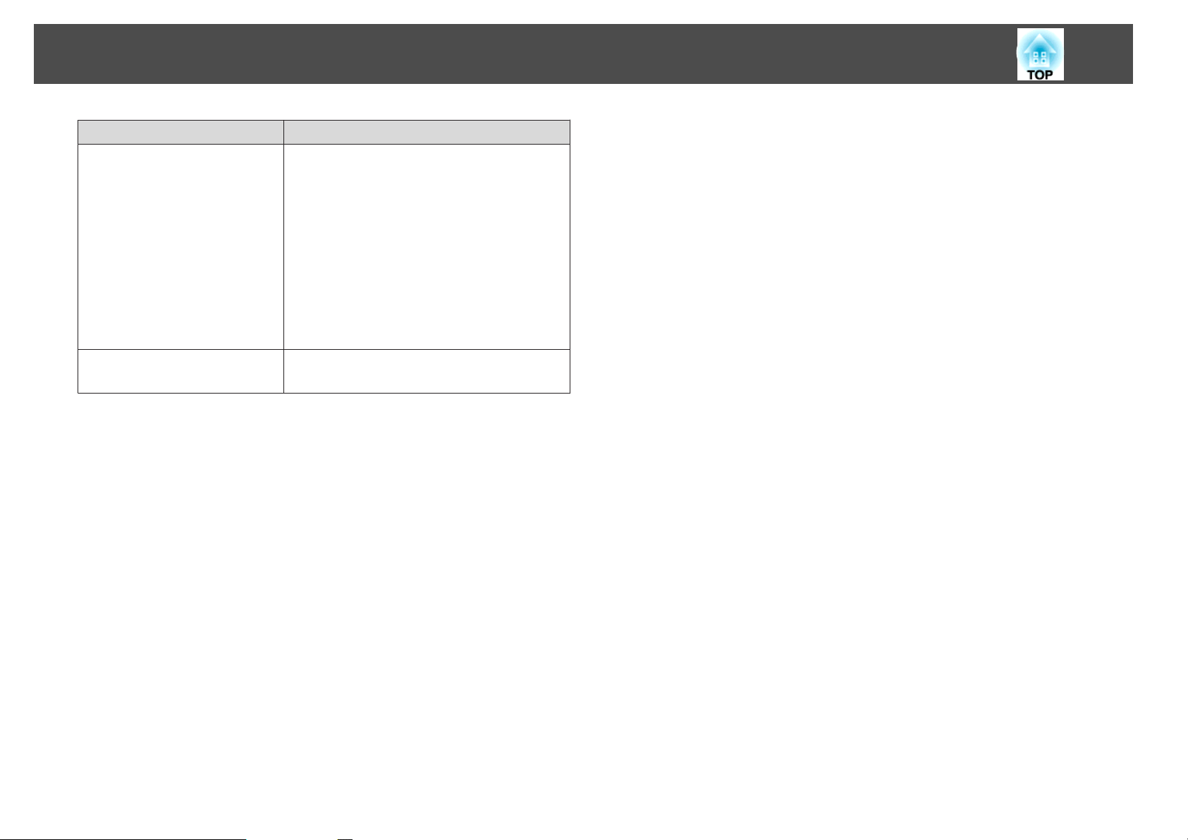
Installing the Projector
Purpose Setting Methods
To change the screen displayed on
the background.
47
Change from Display. You can select from blue,
black, and logo. If no logo is registered, the
EPSON logo is displayed.
Display Background: Set the screen display with
no image signal input. (Default value: Blue)
s Extended - Display - Display
Background p.147
Startup Screen: Set whether or not (On/Off) to
display the user logo when the projector is turned
on. (Default value: On)
s Extended - Display - Startup Screen p.147
To turn off the LCD display or
control panel buttons
Set Lighting Time to Off on the LCD display.
s "Setting the screen display (LCD)" p.184
Page 48
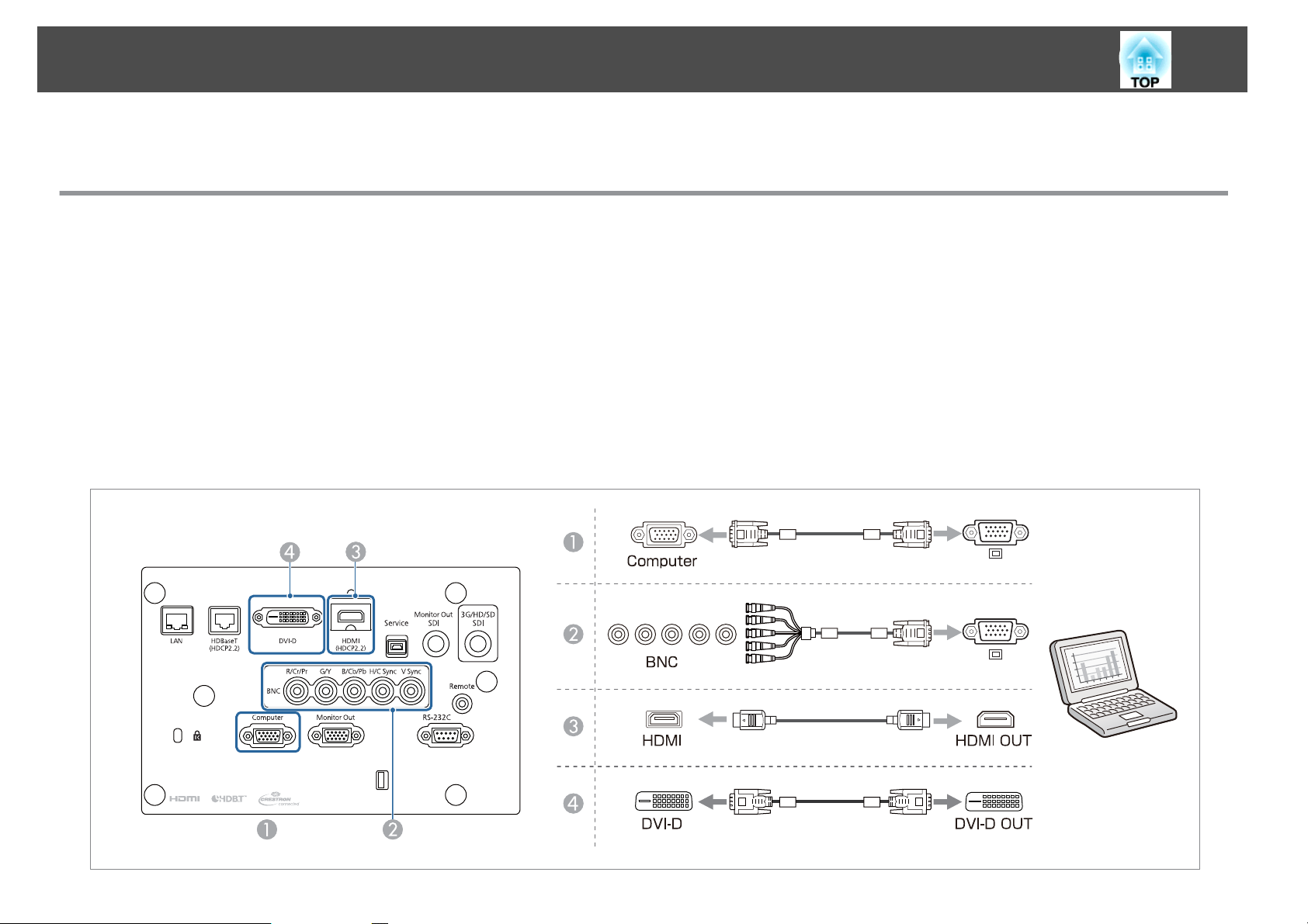
Connecting Equipment
The port name, location, and connector orientation differ depending on the source being connected.
Connecting a Computer
To project images from a computer, connect the computer using one of the following methods.
When using a commercially available computer cable
A
Connect the computer's display output port to the projector's Computer port.
When using a commercially available 5BNC cable
B
Connect the computer's display output port to the projector's BNC port.
When using a commercially available HDMI cable
C
Connect the HDMI port on the computer to the projector's HDMI port.
When using a commercially available DVI-D cable
D
Connect the DVI-D port on the computer to the projector's DVI-D port.
48
Page 49
Connecting Equipment
If the source you want to connect to has an unusually shaped port, use the cable supplied with the device or an optional cable to connect to the projector.
a
Make sure the HDMI cable conforms to the HDMI standard. If you use a cable that does not conform to the HDMI standard, images may not be displayed
correctly.
When using the power port for an optical HDMI cable, connect it to the USB-A port.
Images may not be displayed correctly depending on the length and performance quality of the HDMI cable.
Make sure the cable you are using is as short as possible. Images may not display correctly when using a long cable.
49
Page 50
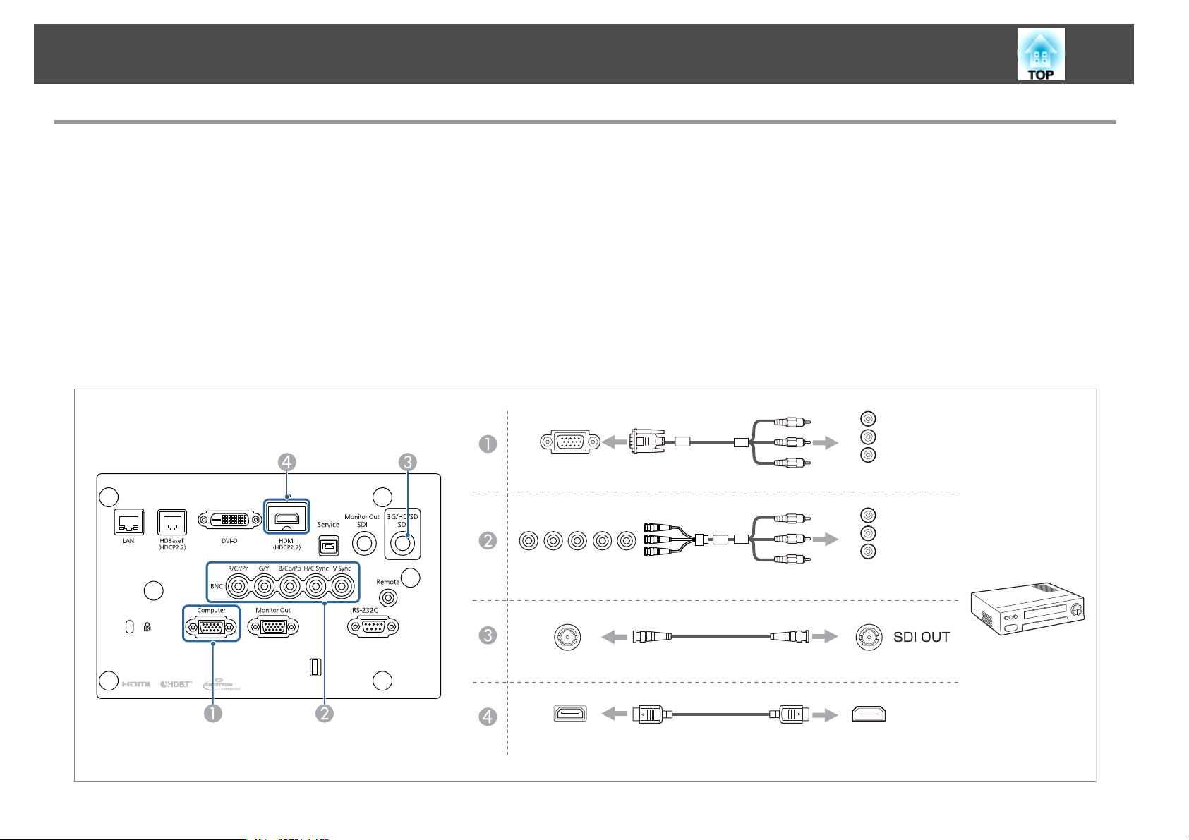
Connecting Equipment
Connecting Image Sources
To project video images, connect to the projector using one of the following methods.
When using a commercially available component video cable (D-sub/component converter)
A
Connect the component output port on the image source to the projector's Computer port.
When using a commercially available component video cable (RCA) and a BNC/RCA adapter
B
Connect the component output port on the video equipment to the projector's BNC port (R/Cr/Pr, G/Y, B/Cb/Pb).
When using a commercially available BNC video cable (SDI input)
C
Connect the SDI port on the image source to the projector's 3G/HD/SD SDI port.
When using a commercially available HDMI cable
D
Connect the HDMI port on the image source to the projector's HDMI port.
Computer
50
Y
Cb/Pb
Cr/Pr
BNC(R/Cr/Pr,G/Y,B/Cb/Pb)
3G/HD/SDSDI
HDMI
Y
Cb/Pb
Cr/Pr
HDMIOUT
Page 51
Connecting Equipment
Attention
If the input source is on when you connect it to the projector, it could cause a malfunction.
If the orientation or shape of the plug differs, do not try to force it in. The device could be damaged or could malfunction.
If the source you want to connect to has an unusually shaped port, use the cable supplied with the device or an optional cable to connect to the projector.
a
Make sure the HDMI cable conforms to the HDMI standard. If you use a cable that does not conform to the HDMI standard, images may not be displayed
correctly.
When using the power port for an optical HDMI cable, connect it to the USB-A port.
Images may not be displayed correctly depending on the length and performance quality of the HDMI cable.
You can set the signal from the 3G/HD/SD SDI port in SDI Settings.
s Extended - SDI Settings p.147
Make sure the cable you are using is as short as possible. Images may not display correctly when using a long cable.
51
Page 52
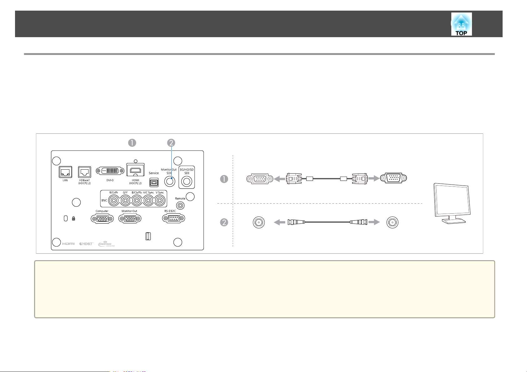
Connecting Equipment
Connecting to an External Monitor
You can output images to an external monitor.
When you want to output images from equipment connected to the Computer port or the BNC port
A
Connect the D-Sub port on the external monitor to the Monitor Out port on the projector.
When you want to output images from equipment connected to the 3G/HD/SD SDI port
B
Connect the SDI OUT port on the external monitor to the Monitor Out SDI port on the projector.
52
MonitorOut D-Sub
a
MonitorOutSDI
Make the following settings to output image even when the projector is in standby mode.
Set A/V Output to Always On.
s Extended - A/V Settings - A/V Output p.147
The Monitor Out port to which external monitors are connected can output analog RGB signals that are being input to the Computer port or the BNC port. You
can set which signals to output in Monitor Out.
s Extended - A/V Settings - Monitor Out p.147
SDIIN
Page 53
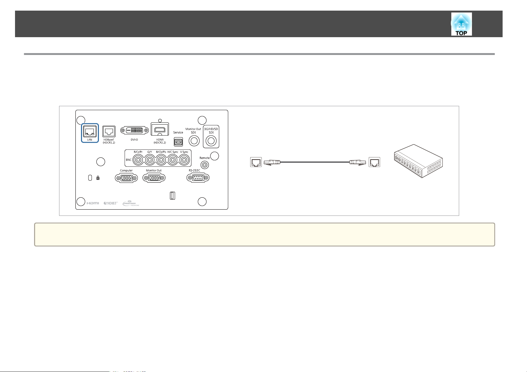
Connecting Equipment
Connecting a LAN Cable
Connect a LAN port on network hubs or other equipment to the projector's LAN port with a commercially available 100BASE-TX or 10BASE-T LAN
cable.
By connecting a computer to the projector over a network, you can project images and check the status of the projector.
LAN
53
a
To prevent malfunctions, use a category 5 or higher shielded LAN cable.
Page 54
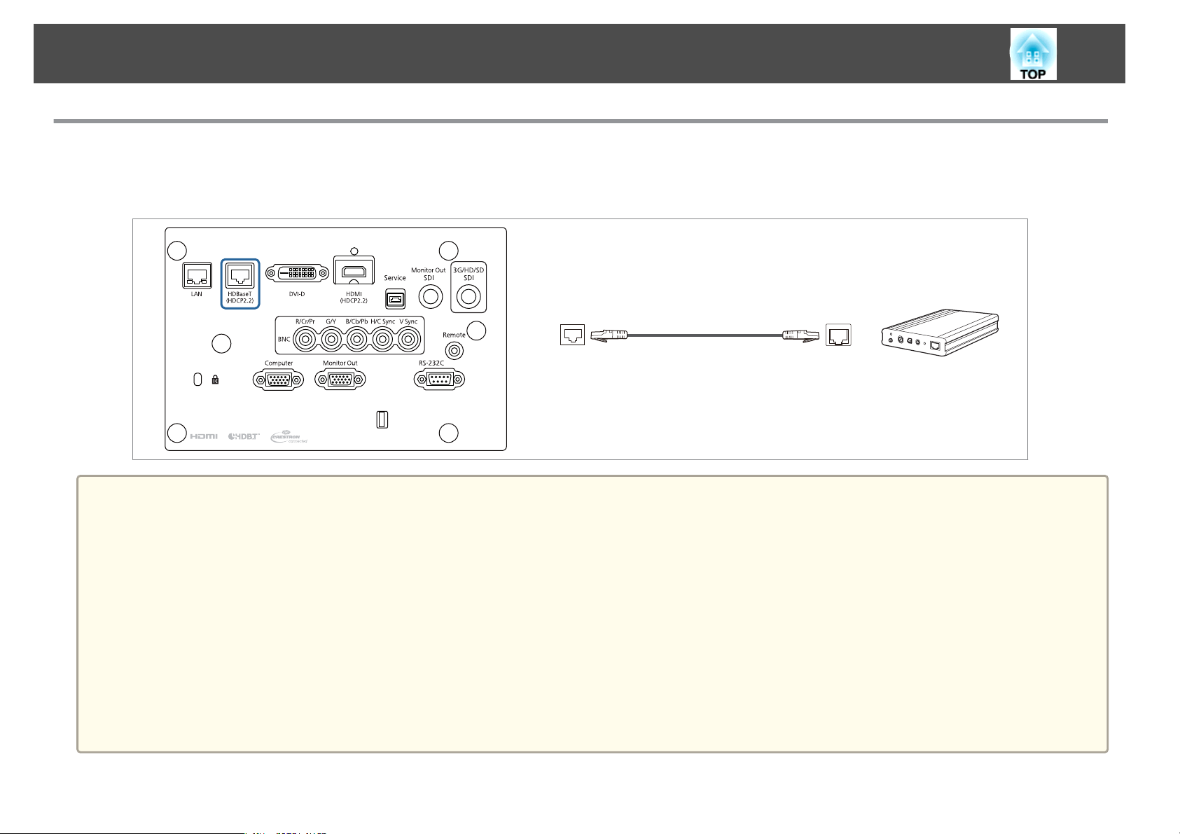
Connecting Equipment
Connecting an HDBaseT Transmitter
Connect the optional HDBaseT Transmitter with a commercially available 100BASE-TX LAN cable.
s
"Optional Accessories" p.252
HDBaseT
54
a
Make sure you read the User's Guide supplied with the HDBaseT Transmitter carefully before use.
For the LAN cable, use an HDBaseT Alliance-recommended STP cable (straight) of category 6 or higher. However, operation is not guaranteed for all input/
output devices and environments.
When connecting or disconnecting the LAN cable, make sure you turn off the power for the projector and the HDBaseT Transmitter.
When performing Ethernet communication or serial communication, or when using the wired remote control via HDBaseT port, set Control Communications
to On from the Configuration menu. The Standby Mode is automatically set to Communication On.
s Extended - HDBaseT - Control Communications p.147
Note that when Control Communications is set to On, the projector's LAN port, RS-232C port, and Remote port are disabled.
When using the Extron XTP transmitter or switcher, connect to the projector's HDBaseT port. Set Extron XTP to On (Control Communications is
automatically set to On, and Standby Mode is automatically set to Communication On).
s Extended - HDBaseT - Extron XTP p.147
You can check the status of the signal being input to the HDBaseT port in HDBaseT Signal Level.
Info - Projector Info - HDBaseT Signal Level p.161
s
Page 55
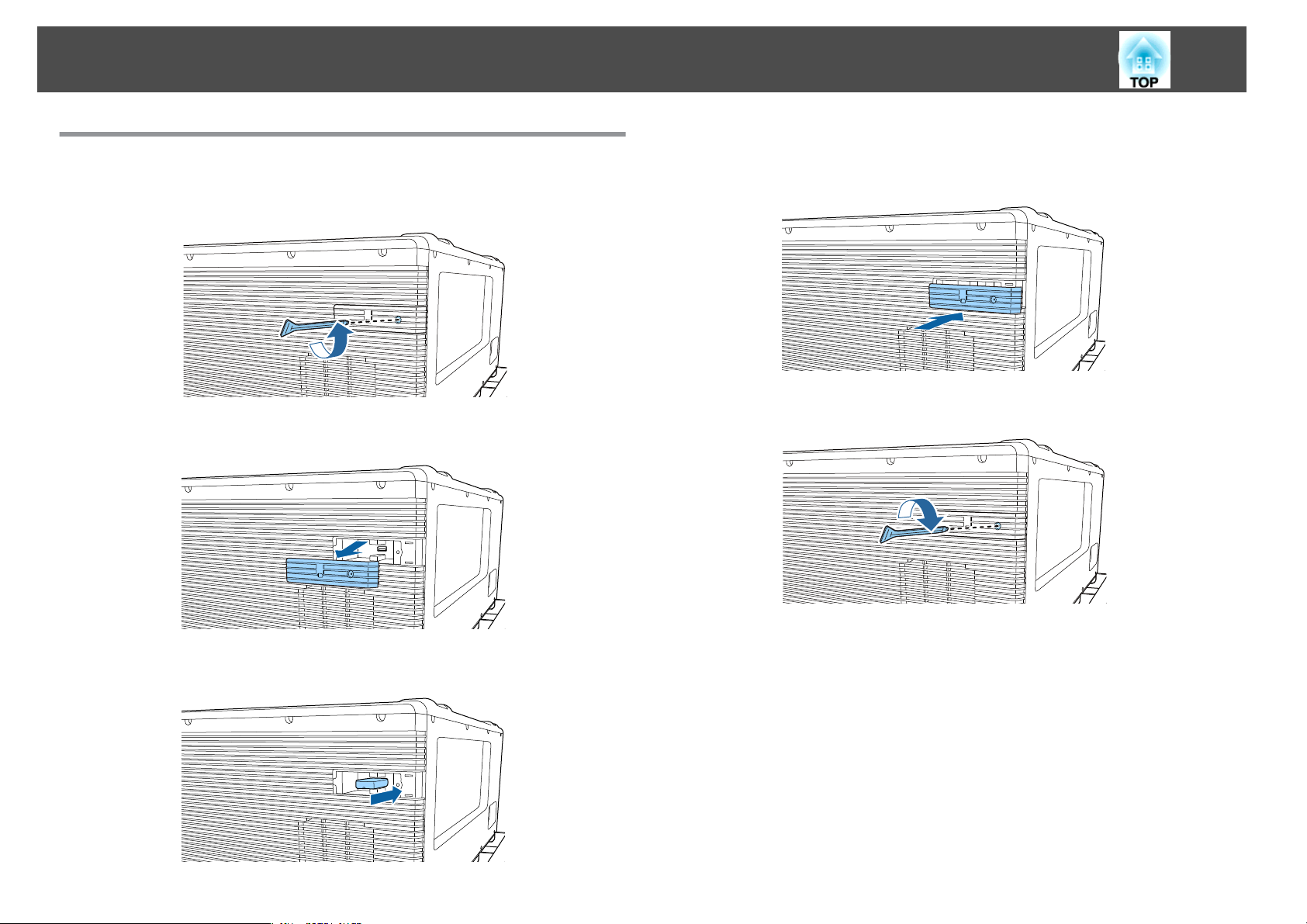
Connecting Equipment
55
Installing the Wireless LAN Unit
Remove the screw for the USB-A port cover.
a
Remove the USB-A port cover.
b
d
Replace the USB-A port cover.
Secure the screw for the USB-A port cover.
e
c
Install the Wireless LAN unit.
You can make wireless LAN connection settings in the Wireless LAN menu
from the Configuration menu.
s
Network - Network Configuration - Wireless LAN p.154
Page 56

Basic Usage
This chapter explains how to project and adjust images.
Page 57
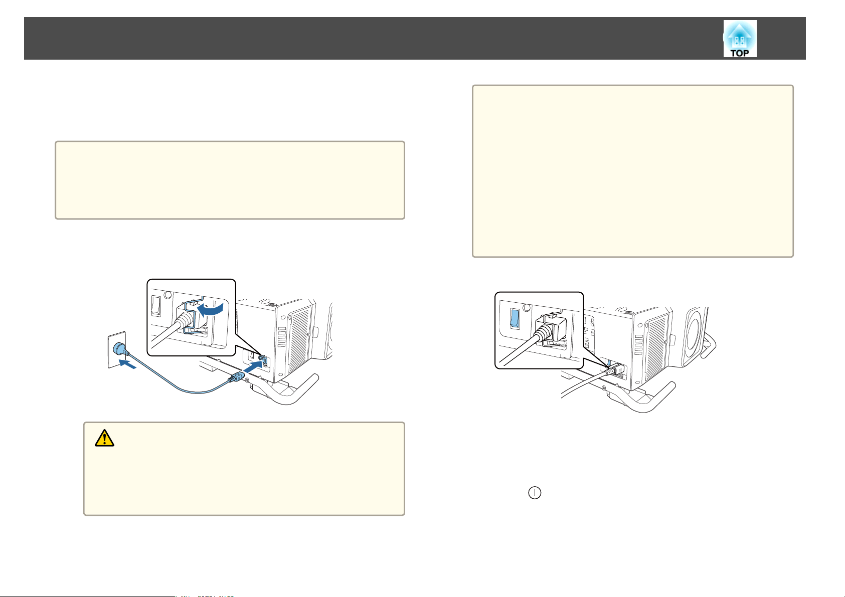
Turning On the Projector
57
Before turning on the projector, connect your computer or video equipment
to the projector.
s
"Connecting Equipment" p.48
Attention
Install the current breaker for 13 A to 20 A to the wiring in the building that
supplies electricity to the projector. Do not connect other devices to the
wiring where the current breaker is installed, and use the wiring only for the
projector.
a
Connect the projector to the power outlet using the power cord,
and then attach the cable holder.
b
You can use the 100 V power cord to operate the projector
a
Turn on the main power switch to supply power to the projector.
temporarily to determine the installation location. When
projecting using the 100 V power cord, the brightness of the
projected image is approximately 30% compared to when using
a 200 V power cord. Use the 200 V power cord when adjusting
the projected image or the lens.
You cannot use the following functions with the 100 V power
cord.
Light Source Mode
Estimated Remains
Refresh Mode
Light Source Calibration
Warning
There are two types of power cord supplied with the projector, 100 V
and 200 V, depending on your country or region. The power cord you
need to use may differ depending on your operating environment.
Contact a specialist to provide information on handling the power
cord.
c
The projector's power indicator turns blue (it is in standby mode).
This indicates that the projector is receiving power, but is not yet
turned on.
Press the [ ] button on the control panel or remote control to
turn on the projector.
The confirmation buzzer beeps and the status indicator flashes blue
as the projector warms up. Once the projector is warmed up, the
status indicator stops flashing and turns blue.
Page 58
Turning On the Projector
If the image is not projected, try the following.
Turn on the connected computer or video equipment.
When using a laptop computer, change the screen output of the
computer.
Insert media such as a DVD and play it back.
Press the [Search] button on the remote control to detect the input
source.
Press the button for the input source that you want to project by using
the remote control.
Warning
Do not look into the projector's lens during projection. Doing so may
damage your eyes. Be especially careful if children are present.
During projection, do not block the light from the projector with a book and
so on. If the light from the projector is blocked for a long time, the area on
which the light shines becomes hot which could cause it to melt, burn, or
start a fire. Also, the lens may get hot due to the reflected light which could
cause the projector to malfunction. To stop projection, use the Shutter
function, or turn off the projector.
58
a
If Direct Power On is set to On in the Extended menu, the
projector automatically turns on when power is supplied to it. When
the power cord is plugged in, note that the projector turns on
automatically in cases such as recovery from a power outage.
s Extended - Operation - Direct Power On p.147
You can set the shutter status when the projector is turned on in
Shutter settings from the Extended menu.
s Extended - Operation - Shutter Settings - Startup p.147
Page 59
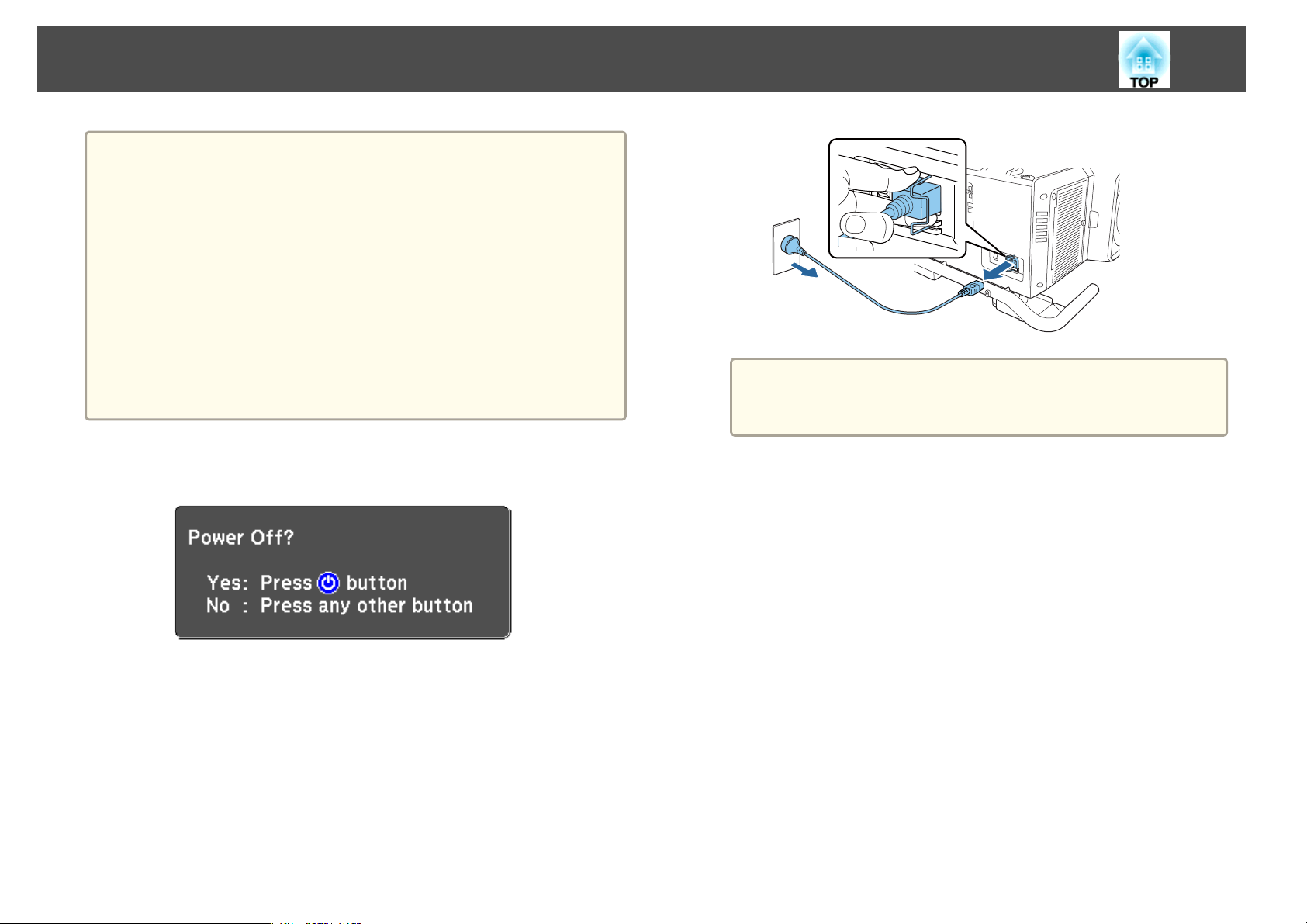
Turning Off the Projector
To ensure a long projector service life, turn off the projector when
a
you are not using it. The light source's operating life varies
depending on the Configuration menu settings, environmental
conditions, and usage conditions. The brightness of the projected
image drops as projection time elapses.
The projector can be powered off directly by the breaker because it
supports the direct shutdown function.
When the projector is used continuously for more than 24 hours, or
when direct shutdown is used regularly, set Light Source
Calibration using the scheduling function to adjust the light source
periodically. You can also make settings from the Configuration
menu.
s "Scheduling Function" p.111
s Reset - Light Source Calibration p.163
a
59
The power cord is shipped according to the power specifications
of the country in which it is sold. If there is a lock on the
power plug, unplug the power cord while pressing the lock.
a
b
c
d
Press the [t] button on the control panel or the remote control.
The shutdown confirmation screen is displayed.
Press the [t] button again. (To cancel, press any other button.)
After the buzzer beeps twice, the projected image disappears, and the
status indicator turns off.
Turn off the main power switch.
The power indicator turns off.
Remove the cable holder and unplug the power cord.
Page 60
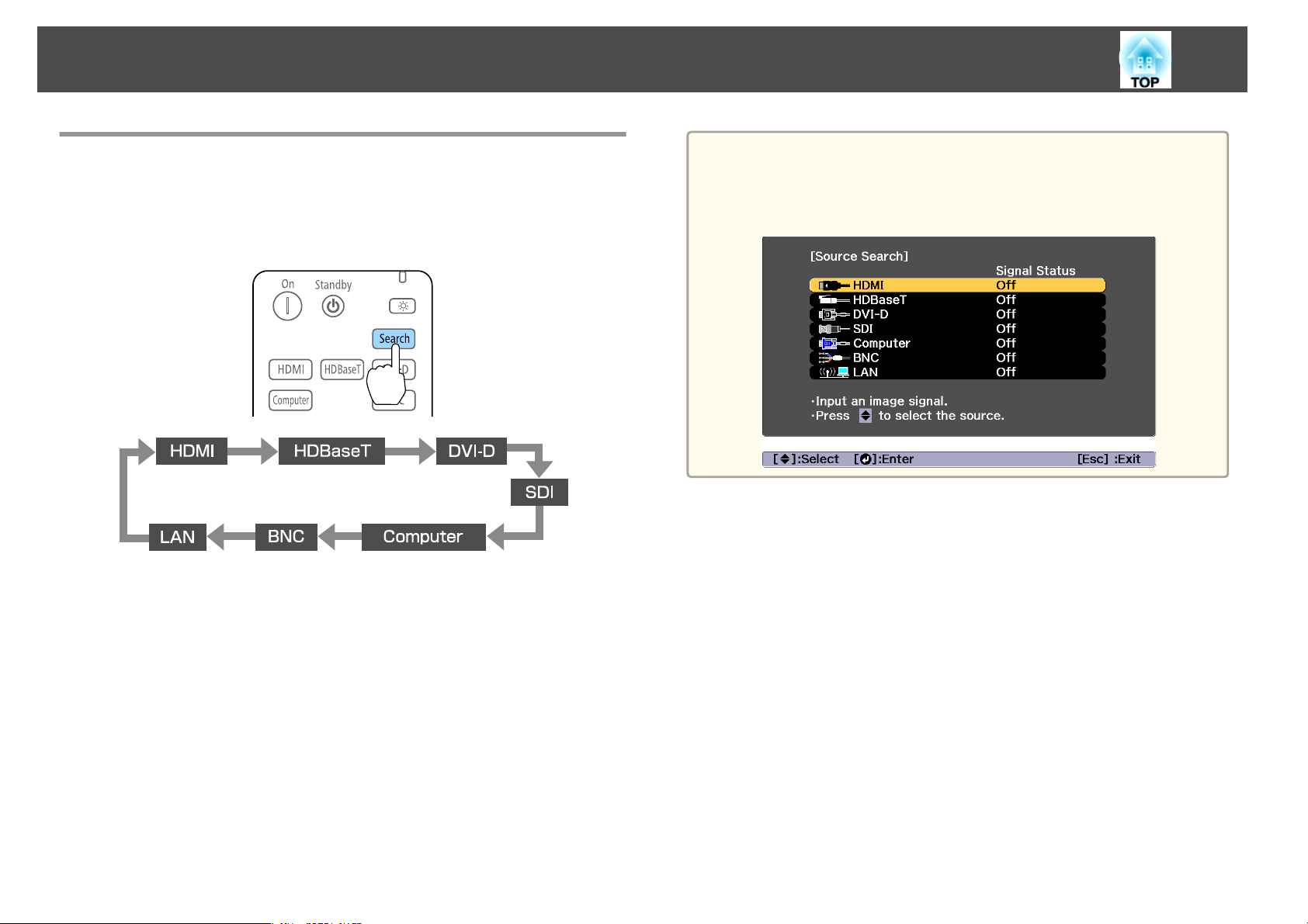
Projecting Images
60
Automatically Detecting Input Signals and Changing the Projected Image (Source Search)
Press the [Search] button on the remote control to project images from the
port currently receiving an image.
When two or more image sources are connected, repeatedly press
the [Search] button until the target image is projected.
a
You can make settings so that images are projected from the same
input port the next time the projector is turned on.
s Extended - Operation - Startup Source Search p.147
The following screen is displayed while no image signals are input.
When your video equipment is connected, start playback before beginning
this operation.
Page 61
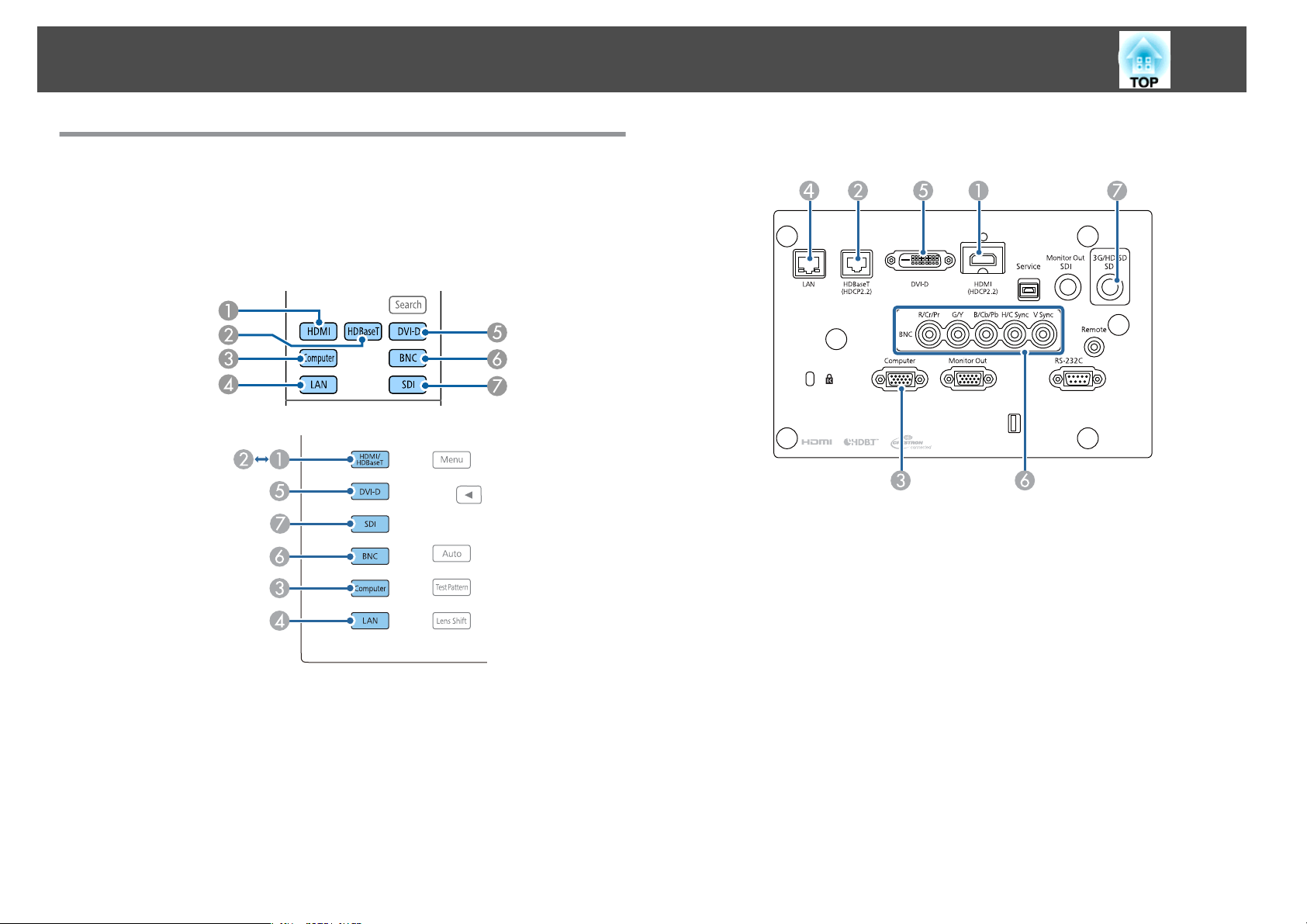
Projecting Images
61
Switching to the Target Image
You can change directly to the target image from the remote control or by
pressing the following buttons on the control panel.
The following shows the input ports for each button.
Remote control
Control panel
Input Port
Changes to images from a computer connected via the network.
D
Page 62
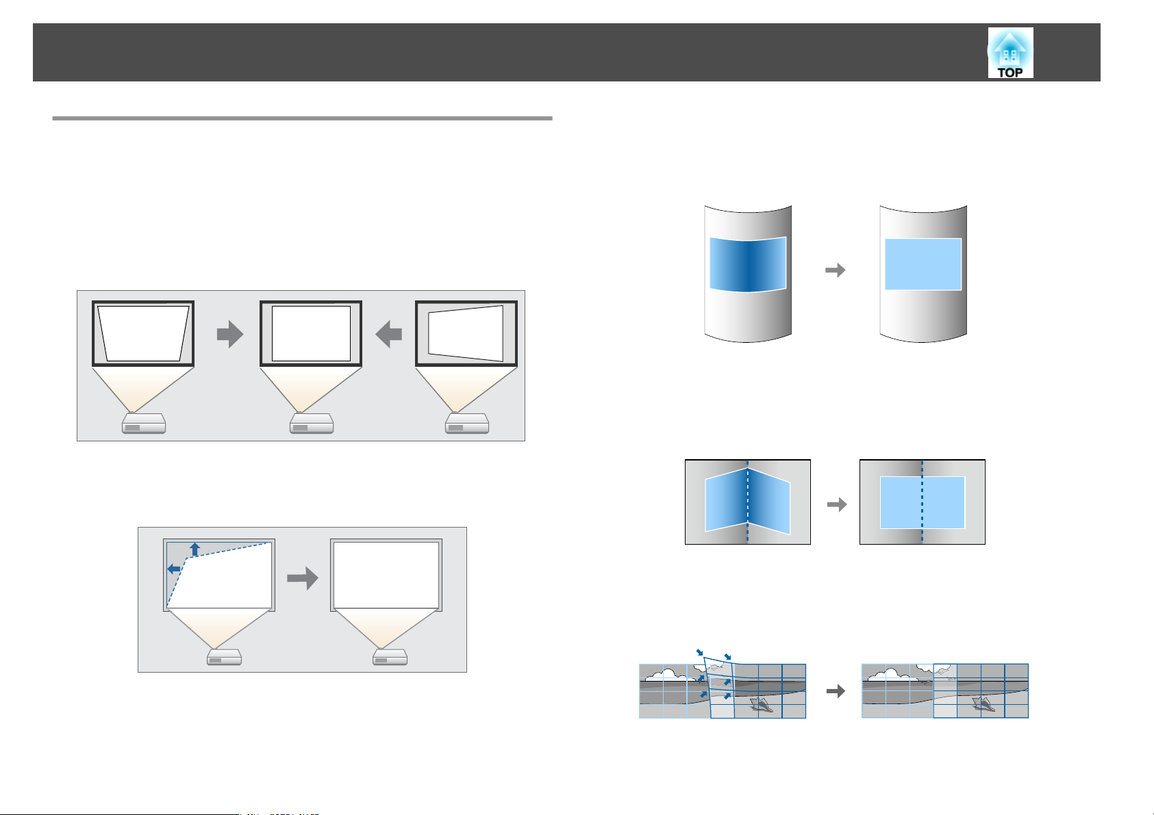
Adjusting Projected Images
62
Correcting Distortion in the Projected Image
You can correct keystone distortion in projected images using one of the
following methods.
H/V-Keystone
This allows you to correct distortion in the horizontal and vertical
directions independently.
s
"H/V-Keystone" p.63
Quick Corner
Correct the four corners independently.
s
"Quick Corner" p.64
Curved Surface
Correct distortion that occurs when projecting on a curved surface, and
adjust the amount of expansion and contraction.
s
"Curved Surface" p.65
Corner Wall
This allows you to correct distortion that occurs when projecting on a
surface with right angles, such as a square pillar or the corner of a room,
and adjust the amount of expansion and contraction.
s
"Corner Wall" p.69
Point Correction
Corrects slight distortion which occurs partially, or adjusts the image
position in an overlapping area when projecting from multiple projectors.
s
"Point Correction" p.72
Page 63
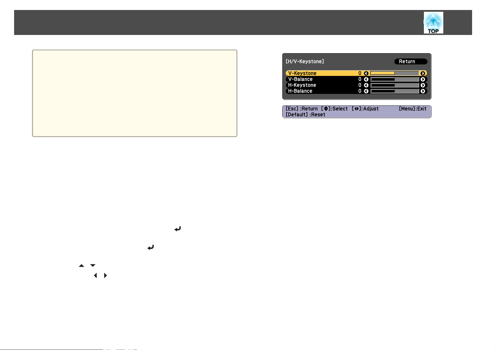
Adjusting Projected Images
When you want to re-adjust the projection position and so on, if
a
H/V-Keystone
This allows you to correct distortion in the horizontal and vertical
directions independently.
Use the following to check the adjustment range for the image.
s
"H/V-Keystone" p.259
you want to release the correction status temporarily, set the
Geometry Correction to Off. Even when it is set to Off, the
correction values are saved.
s Settings - Geometry Correction p.145
You can save the geometry correction settings using Memory in
Geometry Correction, and load them when needed.
s "Memory Function" p.109
You can also make settings from the Configuration menu.
s Settings - Geometry Correction p.145
63
a
b
c
Press the [Geometry] button while projecting.
Select H/V-Keystone, and then press the [ ] button.
When the message "If this setting is changed, the image may be
distorted." is displayed, press the [
Use the [ ][ ] buttons to select the correction method, and
then use the [
][ ] buttons to make the corrections.
] button.
Page 64
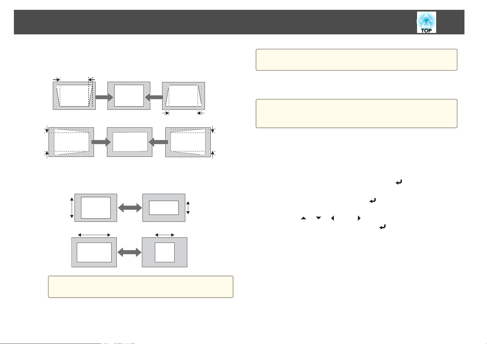
Adjusting Projected Images
64
Correct the keystone distortion by using V-Keystone and HKeystone.
V-Keystone
H-Keystone
If the image aspect is incorrect, adjust the image balance by using
V-Balance and H-Balance.
V-Balance
H-Balance
You cannot combine with other correction methods.
a
Quick Corner
You can project beyond the edges of the projected screen. However,
a
This allows you to correct each of the four corners of the projected image
independently.
a
b
c
once you reach the limit of how much correction can be performed,
you cannot correct the image any further.
Press the [Geometry] button while projecting.
Select Quick Corner, and then press the [ ] button.
When the message "If this setting is changed, the image may be
distorted." is displayed, press the [
Use the [ ], [ ], [ ], and [ ] buttons to select the corner you
want to adjust, and then press the [
] button again.
] button.
d
When you correct keystone distortion, the projected image may
a
To complete the corrections, press the [Menu] button.
be reduced.
Page 65
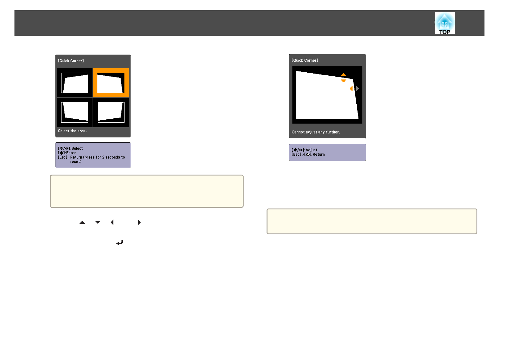
Adjusting Projected Images
65
d
If the [Esc] button is pressed for approximately two seconds,
a
Use the [ ], [ ], [ ], and [ ] buttons to correct the position of
the corner.
When you press the [
allows you to select the area to be corrected is displayed.
If the message "Cannot adjust any further." is displayed while
adjusting, you cannot adjust the shape any further in the direction
indicated by the gray triangle.
the confirm default reset screen is displayed.
Select Yes to reset the result of Quick Corner corrections.
] button, the screen shown in step 3 that
e
Repeat steps 3 and 4 as needed to adjust any remaining corners.
f
To complete the corrections, press the [Menu] button.
Point Correction allows you to fine tune the corrected results.
a
Curved Surface
This allows you to correct distortion that occurs when projecting on a
curved surface, and adjust the amount of expansion and contraction.
Face the projector directly opposing the screen with the lens position
moved to the home position.
s
p.37
s "Point Correction" p.72
"Adjusting the Position of the Projected Image (Lens Shift Adjustment)"
Page 66
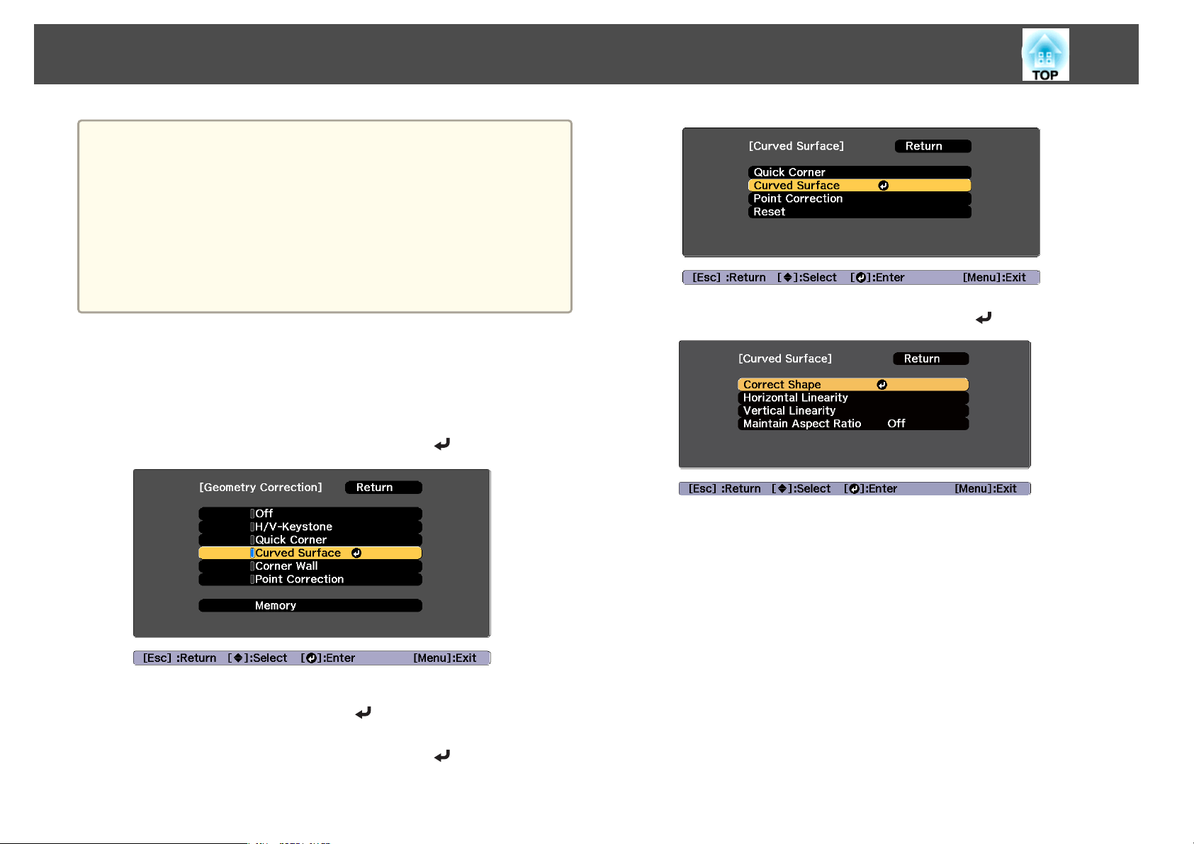
Adjusting Projected Images
Project onto an arc surface with the same radius.
a
Use the following to check the adjustment range for the image.
s
If a large amount of adjustment is performed, the focus may not be
uniform even after making adjustments.
If 4K Enhancement is enabled, a message is displayed. Select Yes to
disable 4K Enhancement.
s Image - Image Enhancement - 4K Enhancement p.141
You can project beyond the edges of the projected screen. However,
once you reach the limit of how much correction can be performed,
you cannot correct the image any further.
"Curved Surface" p.259
66
Select Correct Shape, and then press the [ ] button.
d
a
b
c
Press the [Geometry] button while projecting.
Select Curved Surface, and then press the [ ] button.
When the message "If this setting is changed, the image may be
distorted." is displayed, press the [
Select Curved Surface, and then press the [ ] button.
] button.
Page 67
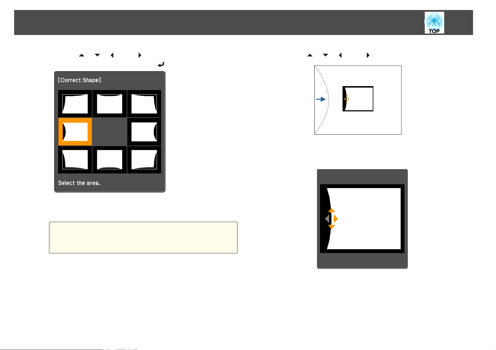
Adjusting Projected Images
67
e
Use the [ ], [ ], [ ], and [ ] buttons to select the area you
want to adjust, and then press the [
When selecting a corner, you can adjust the two sides next to the
corner.
] button.
f
Use the [ ], [ ], [ ], and [ ] buttons to adjust the shape.
If the triangle in the direction you are adjusting the shape turns gray,
as shown in the screenshot below, you cannot adjust the shape any
further in that direction.
a
If the [Esc] button is pressed for approximately two seconds,
the confirm default reset screen is displayed.
Select Yes to reset the result of Curved Surface.
g
h
Press the [Esc] button to return to the previous screen.
Repeat steps from 5 to 7 as needed to adjust any remaining
parts.
If the image expands or contracts, go to the next step and adjust the
linearity.
Page 68
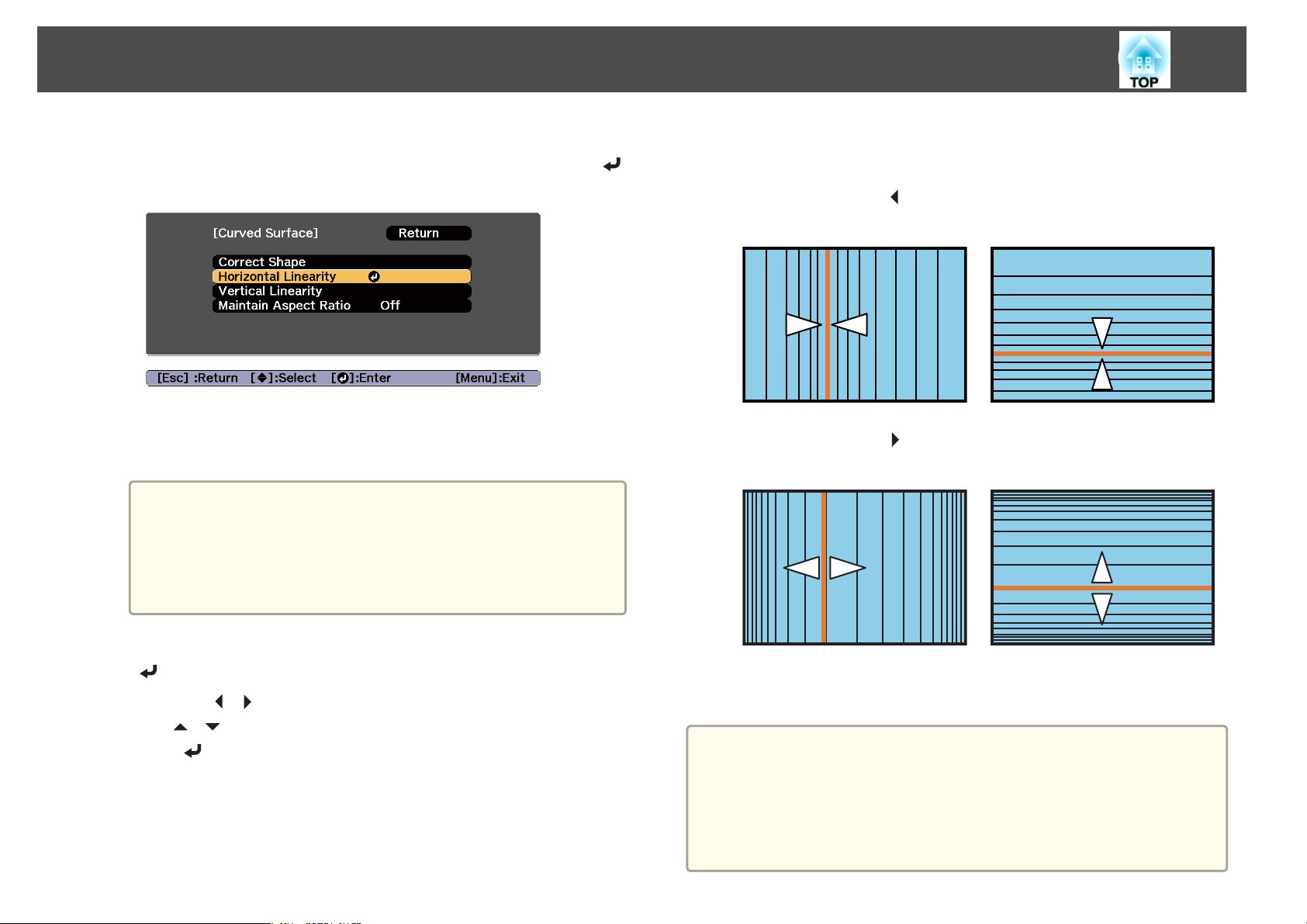
Adjusting Projected Images
68
i
Press the [Esc] button to return to the screen in step 4. Select
Horizontal Linearity or Vertical Linearity, and then press the [
button.
Select Horizontal Linearity to adjust the horizontal expansion or
contraction, and select Vertical Linearity to adjust the vertical
expansion or contraction.
To compensate for expansion or contraction while maintaining
a
the aspect ratio, set Maintain Aspect Ratio to On. You may not
be able to perform corrections if you set this to On after
correction. In this situation, return the corrections to their
initial values, or reduce the amount of correction, and then try
again.
]
k
Adjust the linearity.
Correct it so that the distance between lines is equal.
When pressing the [
When Horizontal Linearity is selected When Vertical Linearity is selected
When pressing the [ ] button
When Horizontal Linearity is selected When Vertical Linearity is selected
] button
j
Select the standard line for the adjustments, and then press the
[
] button.
Press the [
the [
press [
The selected standard line is displayed in flashing orange and white.
Changing the standard line resets the previous settings.
][ ] buttons when selecting Horizontal Linearity, and
][ ] buttons when selecting Vertical Linearity, and then
].
l
a
To complete the corrections, press the [Menu] button.
You can fine tune the corrected results. Use Quick Corner to adjust
the tilt of the image, and then use Point Correction for fine tuning.
Select Quick Corner or Point Correction on the screen from step
3.
s "Quick Corner" p.64
s "Point Correction" p.72
Page 69
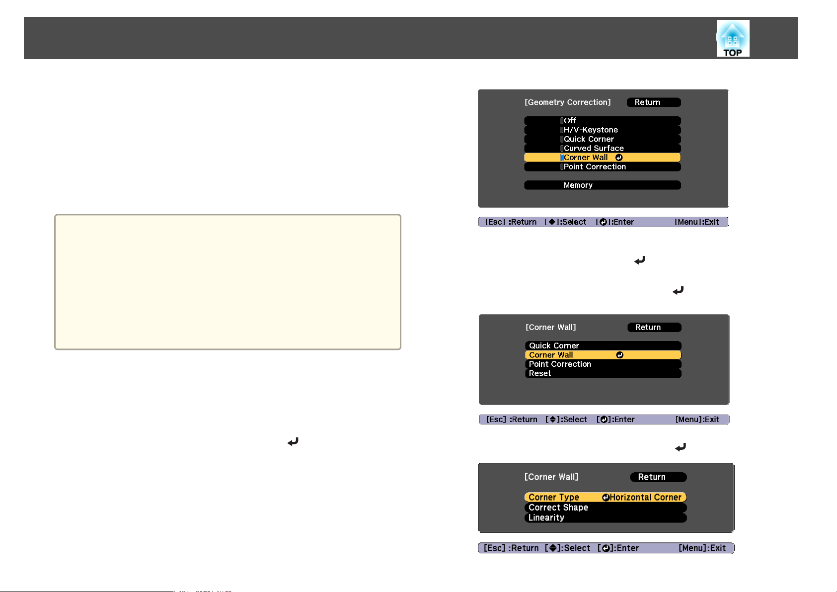
Adjusting Projected Images
Corner Wall
This allows you to correct distortion that occurs when projecting on a
surface with right angles, such as a square pillar or the corner of a room,
and adjust the amount of expansion and contraction.
Face the projector directly opposing the screen with the lens position
moved to the home position.
s
"Adjusting the Position of the Projected Image (Lens Shift Adjustment)"
p.37
Project onto a surface with a right angle.
a
If a large amount of adjustment is performed, the focus may not be
uniform even after making adjustments.
If 4K Enhancement is enabled, a message is displayed. Select Yes to
disable 4K Enhancement.
s Image - Image Enhancement - 4K Enhancement p.141
You can project beyond the edges of the projected screen. However,
once you reach the limit of how much correction can be performed,
you cannot correct the image any further.
c
When the message "If this setting is changed, the image may be
distorted." is displayed, press the [
Select Corner Wall, and then press the [ ] button.
] button again.
69
Use the following to check the adjustment range for the image.
s
"Corner Wall" p.261
Press the [Geometry] button while projecting.
a
b
Select Corner Wall, and then press the [ ] button.
d
Select Corner Type, and then press the [ ] button.
Page 70
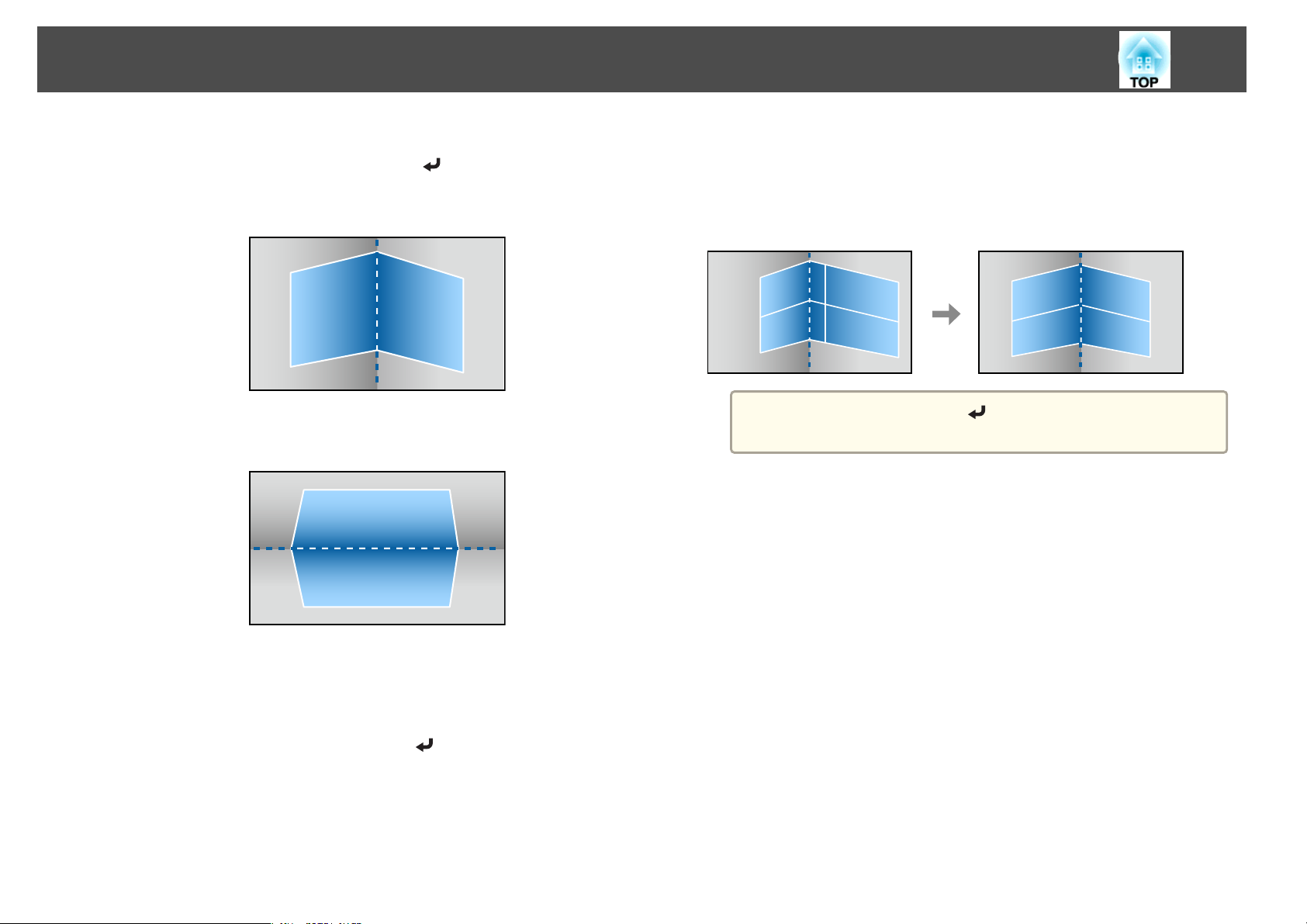
Adjusting Projected Images
70
e
According to the projection area, select Horizontal Corner or
Vertical Corner, and then press the [
When the surfaces line up horizontally:
Select Horizontal Corner.
When the surfaces line up vertically:
Select Vertical Corner.
] button.
g
Adjust the position of the projector and the lens shift so that the
line in the center of the screen matches the corner (the point
where the two surfaces meet).
s
"Adjusting the Position of the Projected Image (Lens Shift
Adjustment)" p.37
Each time you press the [ ] button, you can show or hide the
a
image and the grid.
f
From here on, steps are explained using Horizontal Corner as an
example.
Press the [Esc] button to display the screen from step 4. Select
Correct Shape, and then press the [
] button.
Page 71
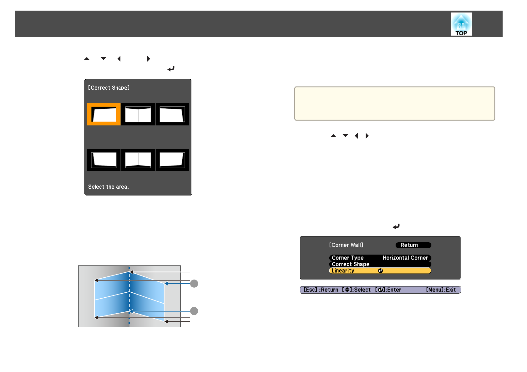
Adjusting Projected Images
71
h
Use the [ ], [ ], [ ], and [ ] buttons to select the area you
want to adjust, and then press the [
Adjustment tips
When Horizontal Corner is selected:
Adjust the upper area based on the lowest point (indicated by the
arrow).
Adjust the lower area based on the highest point (indicated by the
arrow).
] button.
U
V
i
j
k
When Vertical Corner is selected:
Adjust the left and right based on the point nearest to the vertical
line in the center of the screen.
If the [Esc] button is pressed for approximately two seconds,
a
Press the [ ][ ][ ][ ] buttons to adjust the shape.
If the message "Cannot adjust any further." is displayed while
adjusting, you cannot adjust the shape any further in the direction
indicated by the gray triangle.
Repeat steps 8 and 9 as needed to adjust any remaining parts.
If the image expands or contracts, go to the next step and adjust the
linearity.
Press the [Esc] button to display the screen from step 3. Select
Linearity, and then press the [
the confirm default reset screen is displayed.
Select Yes to reset the result of Corner Wall.
] button.
A
B
Page 72
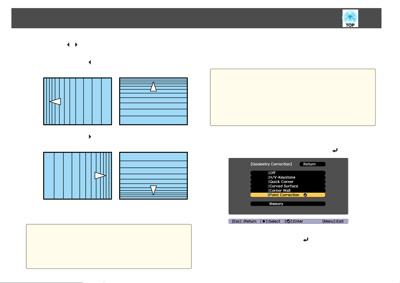
Adjusting Projected Images
72
l
Press the [ ][ ] buttons to adjust the linearity.
Correct it so that the distance between lines is equal.
When pressing the [
When Horizontal Corner is selected When Vertical Corner is selected
When pressing the [ ] button
When Horizontal Corner is selected When Vertical Corner is selected
] button
Point Correction
Divides the projected image by the grid and corrects the distortion by
moving the point of intersection from side to side and up and down.
You can make corrections by 0.5 pixels in each direction up to a
a
maximum of 32 pixels.
If 4K Enhancement is enabled, a message is displayed. Select Yes to
disable 4K Enhancement.
s Image - Image Enhancement - 4K Enhancement p.141
You can project beyond the edges of the projected screen. However,
once you reach the limit of how much correction can be performed,
you cannot correct the image any further.
Press the [Geometry] button while projecting.
a
b
Select Point Correction, and then press the [ ] button.
m
a
To complete the corrections, press the [Menu] button.
You can fine tune the corrected results. Use Quick Corner to adjust
the tilt of the image, and then use Point Correction for fine tuning.
Select Quick Corner or Point Correction on the screen from step
3.
s "Quick Corner" p.64
s "Point Correction" p.72
When the message "If this setting is changed, the image may be
distorted." is displayed, press the [
] button again.
Page 73
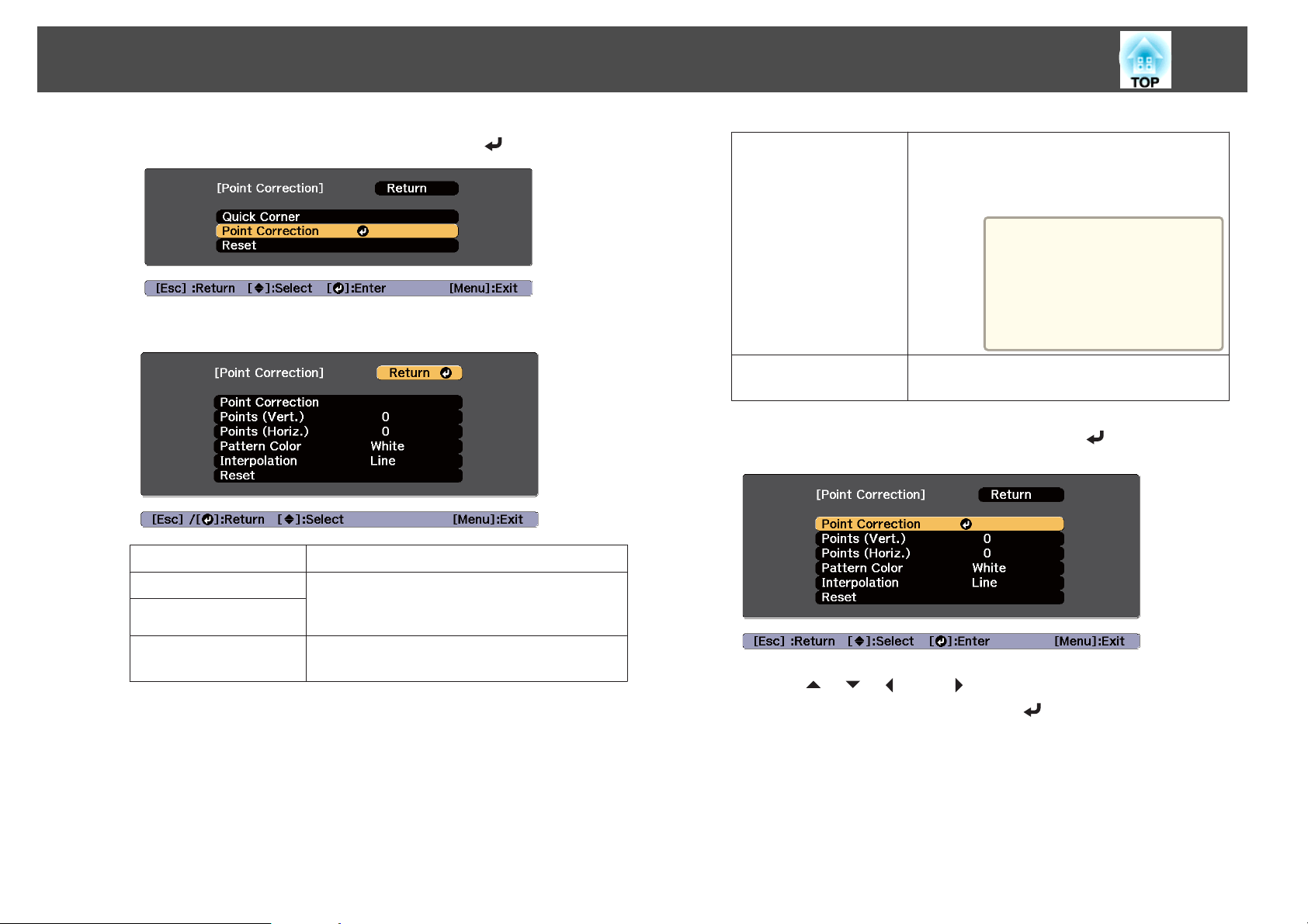
Adjusting Projected Images
73
c
d
Select Point Correction, and then press the [ ] button.
Set each item on the following screen.
Point Correction
Points (Vert.)
Points (Horiz.)
Starts Point Correction.
Sets the number of points in the vertical and
horizontal directions. Select the number of points
from 3, 5, 9, 17, or 33.
e
Interpolation
Reset
Select Point Correction, and then press the [ ] button.
Select the display format for the lines that connect
the points. Line is most suitable when projecting
onto a flat surface, and Curve is most suitable when
projecting onto an uneven surface.
If you have already made
a
Resets all corrections for Point Correction to their
default values.
corrections using Point
Correction, you may not
be able to change Interpo‐
lation if the amount of
correction is too large.
Pattern Color
Select the color of the grid when performing
corrections.
f
Use the [ ], [ ], [ ], and [ ] buttons to move to the point you
want to correct, and then press the [
] button.
Page 74
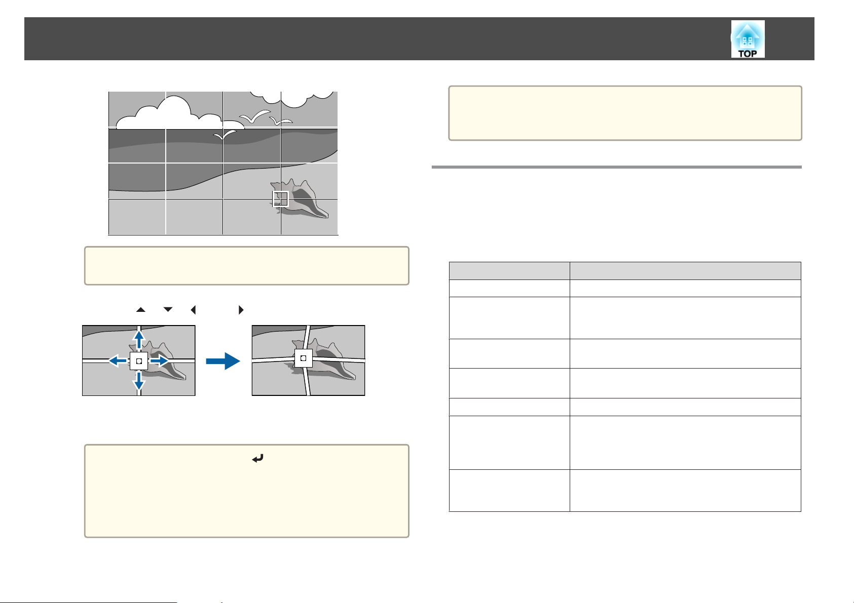
Adjusting Projected Images
The Edge Blending settings are temporarily disabled while the
a
Use the [ ], [ ], [ ], and [ ] buttons to correct distortion.
grid is displayed.
g
74
You can fine tune the corrected results. Select Quick Corner on the
a
screen from step 3 to adjust the tilt of the image.
s "Quick Corner" p.64
Selecting the Projection Quality (Selecting Color Mode)
You can easily obtain the optimum image quality simply by selecting the
setting that best corresponds to your surroundings when projecting. The
brightness of the image varies depending on the mode selected.
Mode Application
Dynamic
Presentation
This is the brightest mode. Ideal for use in a bright room.
The images are vivid and brought to life. Ideal for
making presentations or watching a TV program in a
bright room.
h
To continue to correct another point, press the [Esc] button to
return to the previous screen, then repeat the steps 5 and 6.
Each time you press the [ ] button, you can show or hide
a
To complete the corrections, press the [Menu] button.
the image and the grid.
Even if you change the number of points during correction,
the corrected status is retained.
Coordinates for pixels that extend beyond the edge of the
projected screen are displayed as negative numbers.
Natural
Cinema
BT.709
DICOM SIM
Multi-Projection
Reproduces colors faithfully. Ideal for projecting still
pictures such as photos.
Gives images a natural tone. Ideal for watching films in a
dark room.
Produces images that conform to the ITU-R BT.709.
This produces images with clear shadows. Ideal for
projecting X-ray photographs and other medical
images. The projector is not a medical device and cannot
be used for medical diagnosis.
Minimize the color tone difference between each
projected image. Ideal for projecting from multiple
projectors.
Page 75
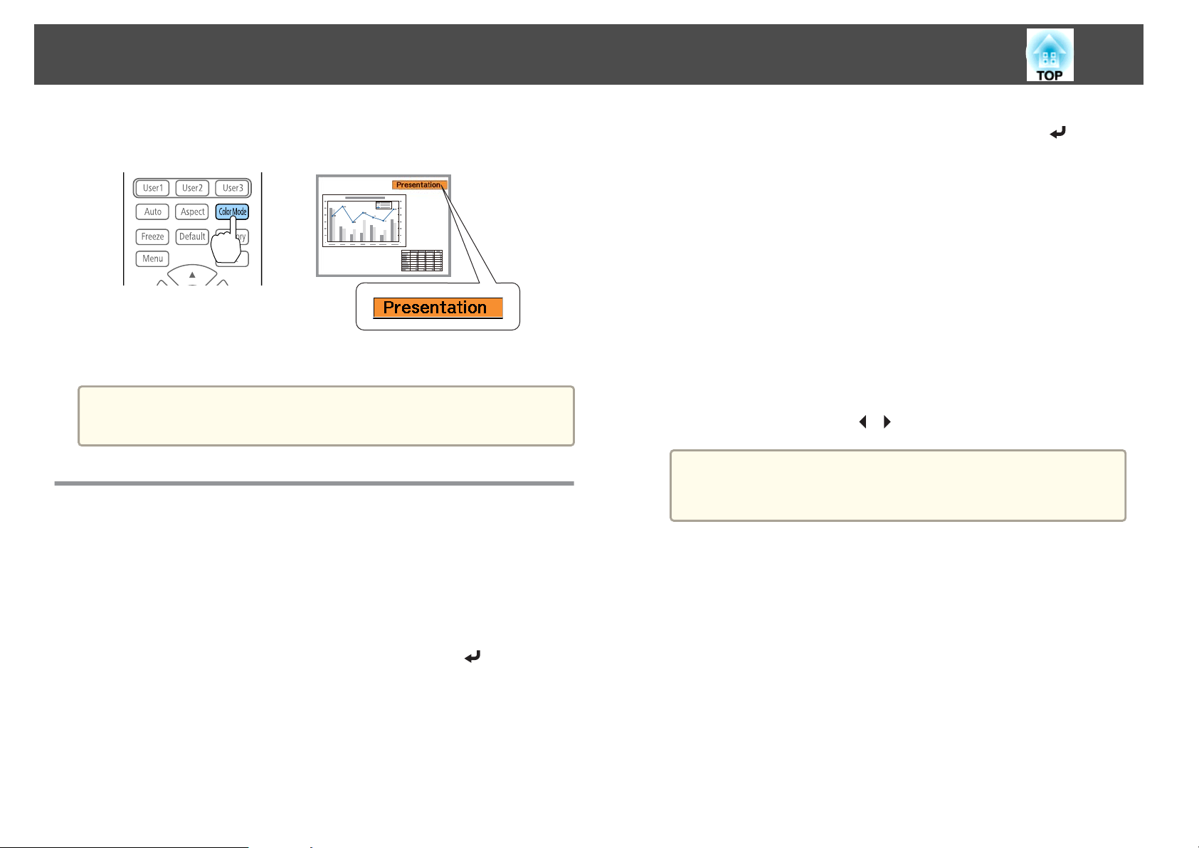
Adjusting Projected Images
75
Each time you press the [Color Mode] button on the remote control, the
Color Mode name is displayed on the screen and the Color Mode changes.
The Color Mode is saved for each input source.
You can set Color Mode from the Configuration menu.
a
s Image - Color Mode p.141
Setting the Brightness
Set the brightness for the light source.
Press the [Menu] button while projecting.
a
d
e
f
Select the item you want to set, and then press the [ ] button.
Normal: Select this if you do not want to decrease the brightness.
This makes the light source operation time approximately 20,000
hours.
Quiet: Select this if you are concerned about the noise made by the
fan. This sets the brightness at 70%. This makes the light source
operation time approximately 20,000 hours.
Extended: Select this to extend the life expectancy of the light
source. This sets the brightness at 70%. This makes the light source
operation time approximately 43,000 hours.
Custom: Select this to set the Brightness Level manually. When
Custom is selected, Constant Brightness is available.
When Light Source Mode is set to Custom, select Brightness
Level, and then use the [
When there is a limit to the maximum adjustment value for the
a
To maintain a fixed brightness, select Constant Brightness, and
set it to On.
brightness level, the maximum value is displayed below
Brightness Level.
][ ] buttons to set the brightness.
b
c
Select Brightness Settings from Settings.
Select Light Source Mode, and then press the [ ] button.
Page 76
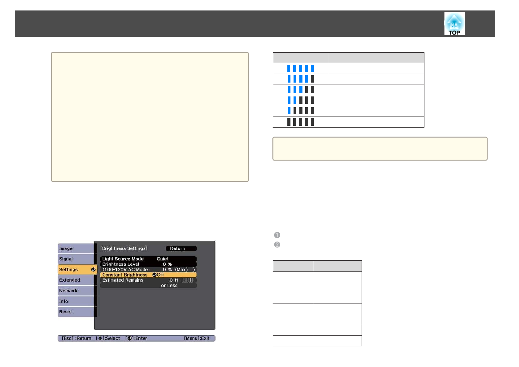
Adjusting Projected Images
76
When Constant Brightness is set to On, you cannot change
a
the settings for Light Source Mode and Brightness Level.
When you want to change these settings, set Constant
Brightness to Off.
When Constant Brightness is set to Off, the value for
Brightness Level changes depending on the current status of
the light source.
There may be a margin of error in the Brightness Level.
When the projector is used continuously for more than 24
hours, or when direct shutdown is used regularly, set Light
Source Calibration using the scheduling function. If this is
not set, the Constant Brightness function does not work. You
can also make settings from the Configuration menu.
s "Scheduling Function" p.111
s Reset - Light Source Calibration p.163
Guide to Estimated Remains
When Constant Brightness is set to On, the Estimated Remains is
displayed. Estimated Remains indicates the amount of time for which
constant brightness can be maintained.
Display Level Actual Time Remaining
10,000 hours or more
8,000 to 9,999 hours
6,000 to 7,999 hours
4,000 to 5,999 hours
2,000 to 3,999 hours
0 to 1,999 hours
Estimated Remains displays the amount of time remaining in hours
a
without the minutes remaining.
Relationship between Brightness Level and light source operation time
The following shows the relationship between Brightness Level and the light
source operation time.
When Constant Brightness is set to Off
: Brightness Level
: Approximate light source operation time until its brightness is reduced
by half
AB
100% 20,000 hours
90% 36,000 hours
80% 41,000 hours
70% 43,000 hours
60% 46,000 hours
50% 57,000 hours
40% 75,000 hours
Page 77
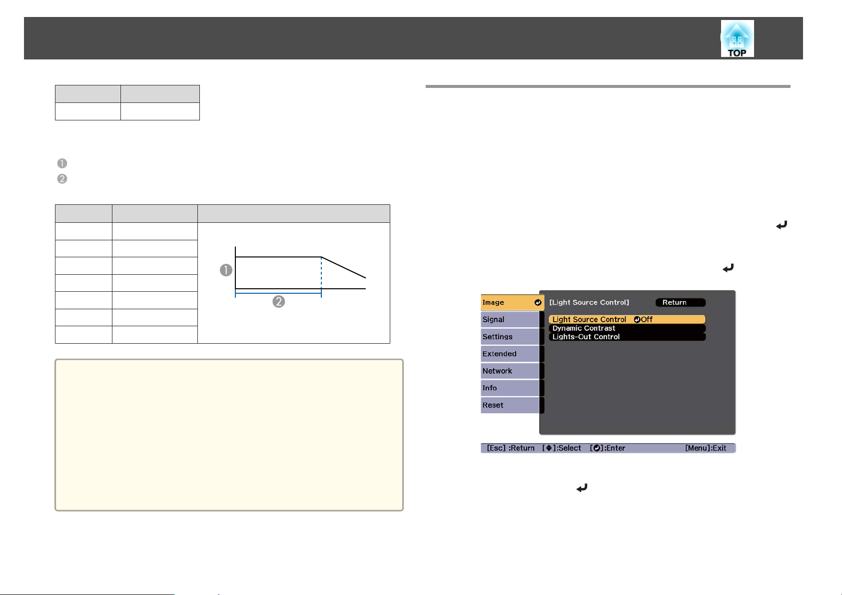
Adjusting Projected Images
77
AB
30% 103,000 hours
When Constant Brightness is set to On
: Brightness Level
: Standard constant time (Approximate time for which constant
brightness of the light source can be maintained)
AB
85% 7,000 hours
80% 15,000 hours
70% 25,000 hours
60% 35,000 hours
50% 47,000 hours
40% 66,000 hours
30% 95,000 hours
This is an approximate guide only and may change depending on
a
the projector’s usage and surroundings.
The times above are the standard hours when using the projector
continuously without changing the Brightness Level or Constant
Brightness settings and are not guaranteed.
This is an approximate guide only and may change depending on
the projector’s usage and surroundings. You may need to replace
internal parts sooner than the estimated light source operation time.
When Constant Brightness is set to On, and the approximate
constant time has been exceeded, you may not be able to set a high
value for Brightness Level.
Illustration
Setting the Amount of Light of the Projected Image
By automatically setting the luminance according to the brightness of the
displayed image, it lets you enjoy deep and rich images. You can also set
the light source to turn off automatically.
Press the [Menu] button while projecting.
a
b
Select Light Source Control from Image, and then press the [ ]
button.
Select Light Source Control, and then press the [ ] button.
c
d
Select the light source operation according to the image signal,
and then press the [
] button.
Page 78
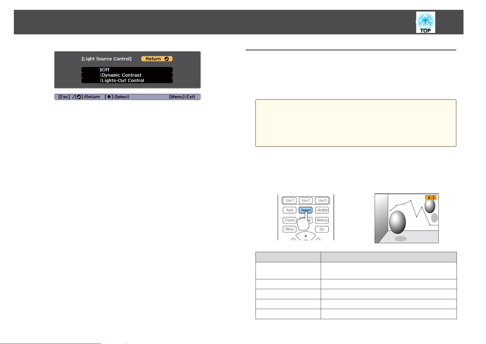
Adjusting Projected Images
78
Changing the Aspect Ratio of the Projected Image
You can change the aspect ratio of the projected image to suit the type, the
ratio of height and width, and the resolution of the input signals.
Available aspect modes vary depending on the Screen Type currently set.
Off: Select if you do not want to control the light source.
Dynamic Contrast: Automatically adjust the amount of light when
projecting according to the brightness of the image.
Lights-Out Control: Automatically turns off the light after the set
time has elapsed at the specified video level.
Press the [Esc] button to return to the previous screen.
e
f
g
If you selected Dynamic Contrast in step 4, make the following
settings in Dynamic Contrast.
Response Speed: Select High Speed to adjust the amount of light
as soon as the scene changes.
Black Level: Set the black level when the brightness level of the
image signal is zero. When you select 0%, the light source turns
off.
If you selected Lights-Out Control in step 4, make the following
settings in Lights-Out Control.
Lights-Out Signal Level: Set the brightness level for the video
signal being controlled. After turning off automatically when
exceeding the specified image level, it turns on immediately.
Lights-Out Timer: Set the amount of time before automatically
turning off the light source.
Press the [Menu] button to finish making settings.
h
Set the Screen Type before changing the aspect ratio.
a
Changing methods
Each time you press the [Aspect] button on the remote control, the aspect
mode name is displayed on the screen and the aspect ratio changes.
Auto
Normal
4:3
16:9
Full
s "Screen Settings" p.34
This cannot be changed when Scale Mode is set to Zoom
Display.
s Signal - Scale - Scale Mode p.143
Aspect Mode Explanation
Projects in an appropriate aspect ratio based on
information from the signal being input.
Projects while retaining the aspect ratio of the input image.
Projects at an aspect ratio of 4:3.
Projects at an aspect ratio of 16:9.
Projects at the full size of the projected screen.
Page 79
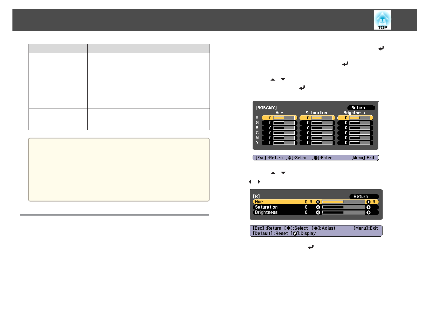
Adjusting Projected Images
79
Aspect Mode Explanation
H-Zoom
V-Zoom
Native
a
The available aspect ratios differ depending on the input signal from
the connected device.
You can also set the aspect ratio from the Configuration menu.
Signal - Aspect p.143
s
If parts of the computer image are missing, set the Resolution
setting to Wide or Normal from the Configuration menu, according
to the resolution of the computer.
Signal - Resolution p.143
s
Projects by enlarging the input image to the full width of
the projected screen while retaining the aspect ratio. Areas
that exceed the edges of the projected screen are not
projected.
Projects by enlarging the input image to the full height of
the projected screen while retaining the aspect ratio. Areas
that exceed the edges of the projected screen are not
projected.
Projects to the center of the projected screen at the
resolution of the input image. Areas that exceed the edges
of the projected screen are not projected.
b
c
d
e
Select Advanced from Image, and then press the [ ] button.
Select RGBCMY, and then press the [ ] button.
Use the [ ][ ] buttons to select the color you want to adjust,
and then press the [
Use the [ ][ ] buttons to select the item, and then use the
[
][ ] buttons to make the adjustments.
] button.
Adjusting the Image
Hue, Saturation, and Brightness adjustment
You can adjust the Hue (tint), Saturation (vividness), and Brightness of
the six axes R (red), G (green), B (blue), C (cyan), M (magenta), and Y
(yellow) according to your preferences.
Press the [Menu] button while projecting.
a
Each time you press the [ ] button, the adjustment screen changes.
To complete the corrections, press the [Menu] button.
f
Page 80
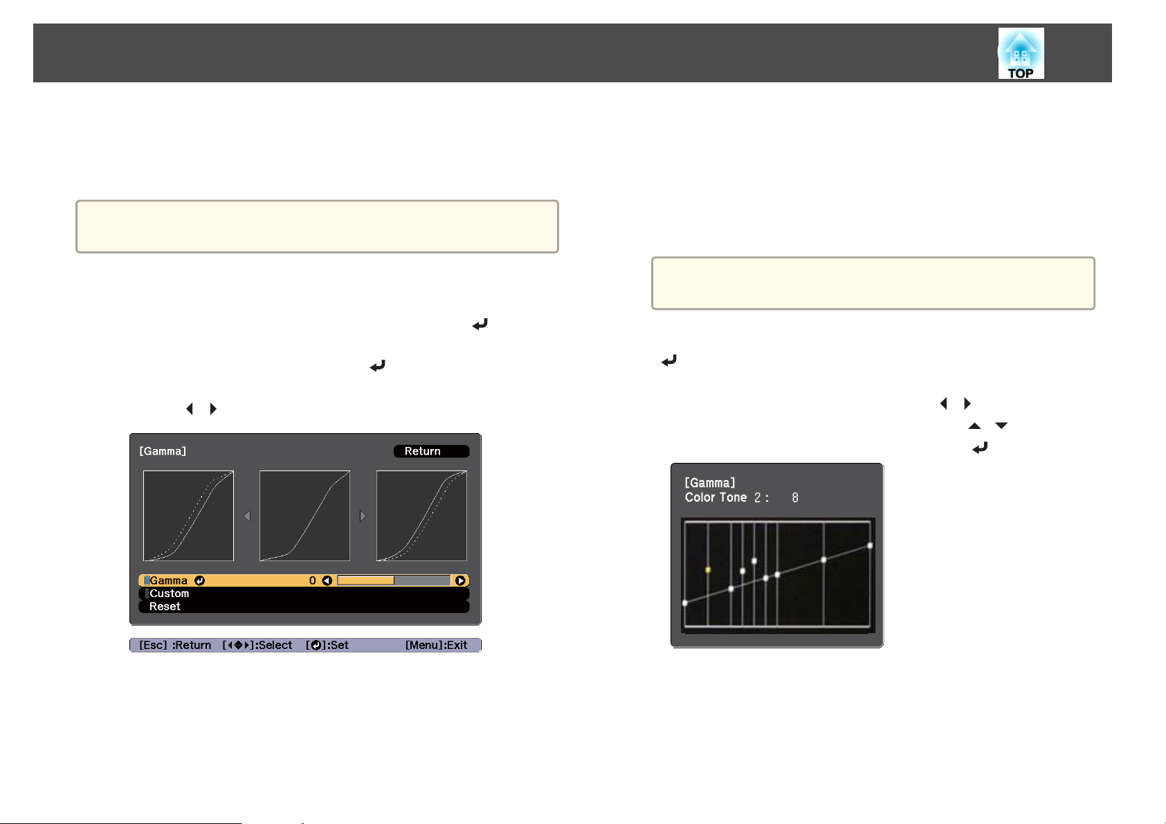
Adjusting Projected Images
80
Gamma adjustment
You can adjust differences in the halftone brightness that occurs depending
on the connected device.
Adjust by projecting a still picture. Gamma cannot be adjusted
a
correctly by using movies.
Press the [Menu] button while projecting.
a
b
Select Advanced from Image, and then press the [ ] button.
c
Select Gamma, and then press the [ ] button.
d
Use the [ ][ ] buttons to adjust the value.
When a smaller value is selected, you can reduce the overall
brightness of the image to make the image sharper.
If you select DICOM SIM from Color Mode on the Image menu,
select the adjustment value according to the projection size.
If the projection size is 300 inches or less, select a small value.
If the projection size is 300 inches or more, select a large value.
Medical images may not be reproduced correctly according to
your installation environment and screen specifications.
] button.
][ ] buttons to
] button.
e
f
a
To make detailed adjustments, select Custom, and then press the
[
In the gamma adjustment graph, use the [ ][ ] buttons to select
the tone that you want to change. Use the [
adjust the selected tone, and then press the [
When a larger value is selected, the dark areas of images become
brighter, but the color saturation for lighter areas may become
weaker.
g
Press the [Menu] button to finish making adjustments.
Page 81
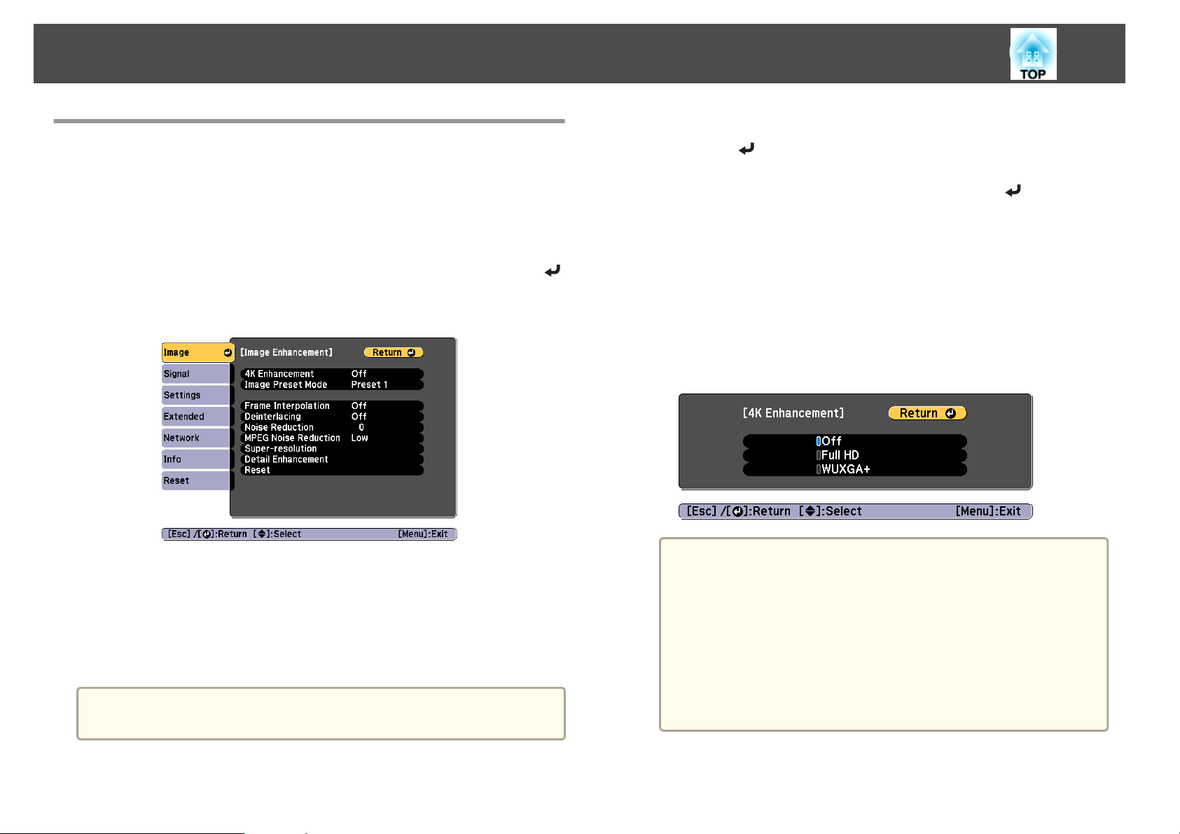
Adjusting Projected Images
81
Adjusting Image Resolution (Image Enhancement)
You can adjust the resolution of the image using Image Enhancement to
reproduce a clear image with an emphatic texture and material feel.
Press the [Menu] button while projecting.
a
b
Select Image Enhancement from Image, and then press the [ ]
button.
The following screen is displayed.
a
b
Select 4K Enhancement from Image Enhancement, and then
press the [
Select one of the following, and then press the [ ] button.
Off: Disables 4K Enhancement. If a signal that exceeds the panel
resolution of this projector is input, the image is displayed according
to the panel resolution of this projector.
Full HD: If a signal with a resolution of 1080i/1080p/WUXGA or
higher is input, 4K Enhancement is enabled.
WUXGA+: If a signal with a resolution that exceeds WUXGA is
input, 4K Enhancement is enabled. To project a high-resolution
movie, you can project a high-definition image by using this setting
with Image Preset Mode.
] button.
4K Enhancement
4K Enhancement is a function that projects an image at a doubled
resolution by diagonally shifting 1 pixel in increments of 0.5 pixels.
A high-resolution image signal is projected in fine detail.
You cannot set 4K Enhancement when Aspect is set to Native.
a
c
To project from multiple projectors, select Off to unify each
a
Press the [Esc] button to return to the previous screen.
image.
Off is ideal for projecting presentation materials from
computers and so on.
If it is set to Full HD or WUXGA+, the status corrected
using the following function is canceled.
Edge Blending, Scale, Curved Surface, Point Correction,
Corner Wall
When 4K Enhancement is set to Off, the settings return to
the previous state before 4K Enhancement was enabled.
Page 82
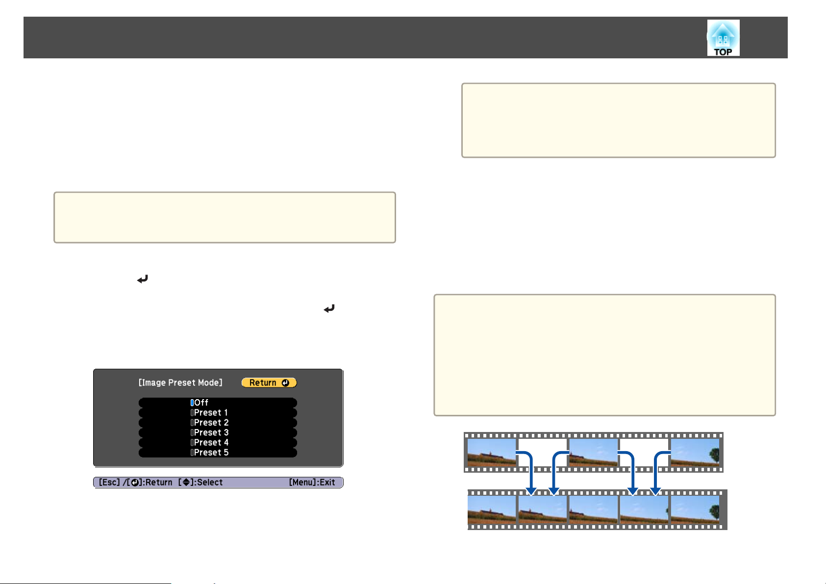
Adjusting Projected Images
82
Image Preset Mode
Select the optimal setting according to the projected image from five presets
prepared in advance.
The following settings are saved in the presets.
Frame Interpolation, Deinterlacing, Noise Reduction, MPEG Noise
Reduction, Super-resolution, Detail Enhancement
To minimize delays, set Image Preset Mode to Off.
a
a
When Image Preset Mode is set to Off, you cannot set the settings
saved in the presets.
Select Image Preset Mode from Image Enhancement, and then
press the [
Select one of the following, and then press the [ ] button.
] button.
b
Preset 1 to Preset 5: The settings saved in advance are applied to the
image.
Off: Select this to turn off presets.
After selecting Preset 1 to Preset 5, you can fine tune each
a
Press the [Esc] button to return to the previous screen.
setting individually. The setting after adjustment will be
overwritten.
The setting after adjustment will be overwritten separately
when 4K Enhancement is enabled and disabled.
c
Frame Interpolation
The current and previous frames are used to create intermediate frames,
interpolating to produce smooth-moving images. You can resolve clumsymoving images, such as frame skipping when projecting a fast moving
image.
You cannot set Frame Interpolation in the following situations.
a
When 4K Enhancement is enabled
When a signal with a horizontal resolution greater than 1920 is
being input
When Aspect is set to V-Zoom
When Scale is set to Auto or Manual
When Edge Blending is set to On
When Image Preset Mode is set to Off
Page 83
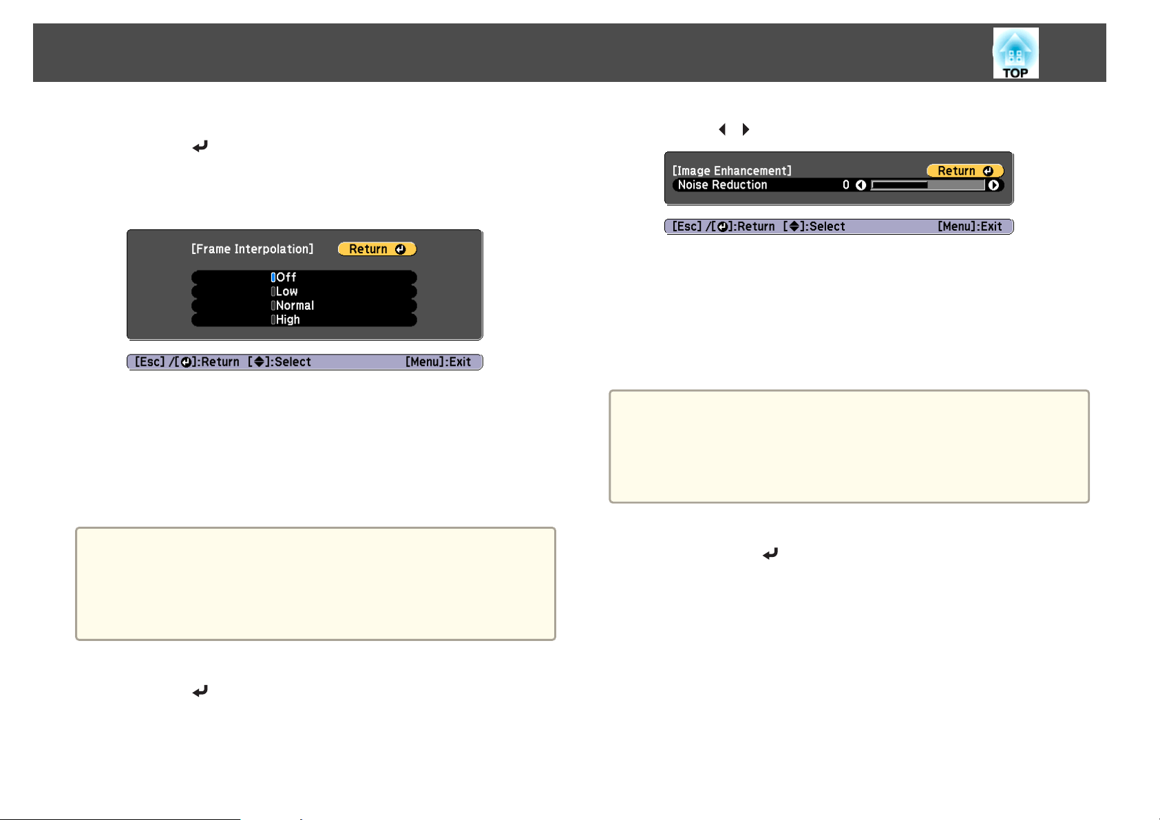
Adjusting Projected Images
83
a
b
Select Frame Interpolation from Image Enhancement, and then
press the [
Select the level of interpolation from Low, Normal or High.
Set to Off if noise occurs after setting them.
Press the [Menu] button to finish making settings.
] button.
c
Noise Reduction
You can smooth out rough images for softer image quality when inputting
progressive signals or progressive interlace signals.
b
Use the [ ][ ] buttons to adjust the value.
c
Press the [Esc] button to return to the previous screen.
MPEG Noise Reduction
You can reduce dot and block noise that occurs in outlines when projecting
MPEG movies.
You cannot set MPEG Noise Reduction in the following situations.
a
When 4K Enhancement is enabled
When a signal with a horizontal resolution greater than 1920 is
being input
When Image Preset Mode is set to Off
a
a
You cannot set Noise Reduction in the following situations.
When 4K Enhancement is enabled
When a signal with a horizontal resolution greater than 1920 is
being input
When Image Preset Mode is set to Off
Select Noise Reduction from Image Enhancement, and then
press the [
] button.
a
Select MPEG Noise Reduction from Image Enhancement, and
then press the [
] button.
Page 84
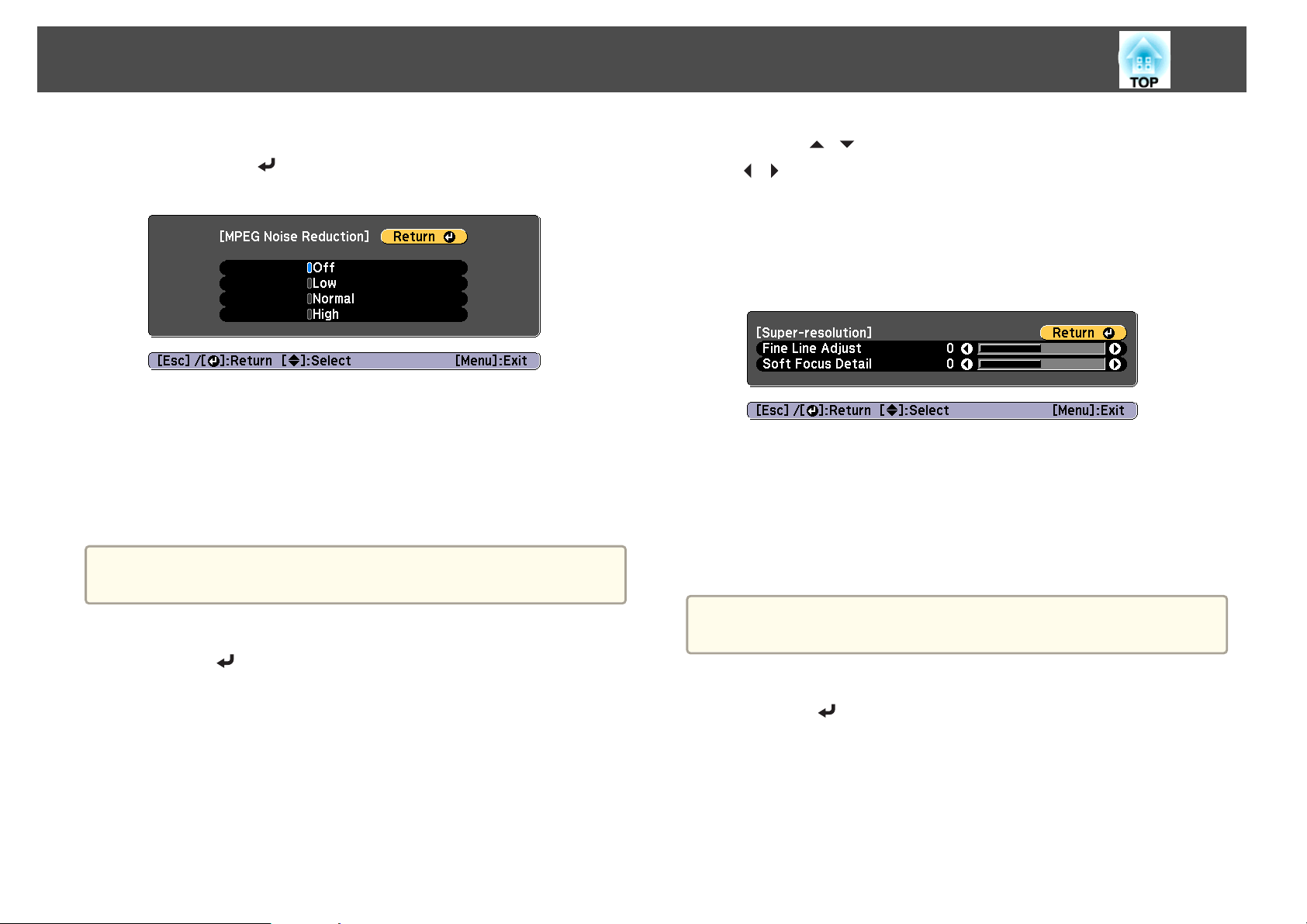
Adjusting Projected Images
84
b
Select a level to reduce noise from Low, Normal, or High, and
then press the [
If Off is selected, MPEG Noise Reduction is disabled.
Press the [Esc] button to return to the previous screen.
] button.
c
Super-resolution
To display a crisp image, you can reduce the blurring that is created on the
edge when the resolution of the image signal is scaled up and projected.
Disabled when Image Preset Mode is set to Off
a
b
Use the [ ][ ] buttons to select the item, and then use the
[
][ ] buttons to make the adjustments.
Fine Line Adjust: If this parameter is set to a positive value, details
such as hair or fabric patterns will be enhanced.
Soft Focus Detail: If this parameter is set to a positive value, the
outline, background, and the other main parts of the objects in the
image will be enhanced to show them clearly.
Press the [Esc] button to return to the previous screen.
c
Detail Enhancement
You can enhance the contrast in detailed areas of an image to create a more
emphatic texture and material feel.
a
Select Super-resolution from Image Enhancement, and then
press the [
] button.
a
a
Disabled when Image Preset Mode is set to Off
Select Detail Enhancement from Image Enhancement, and then
press the [
] button.
Page 85
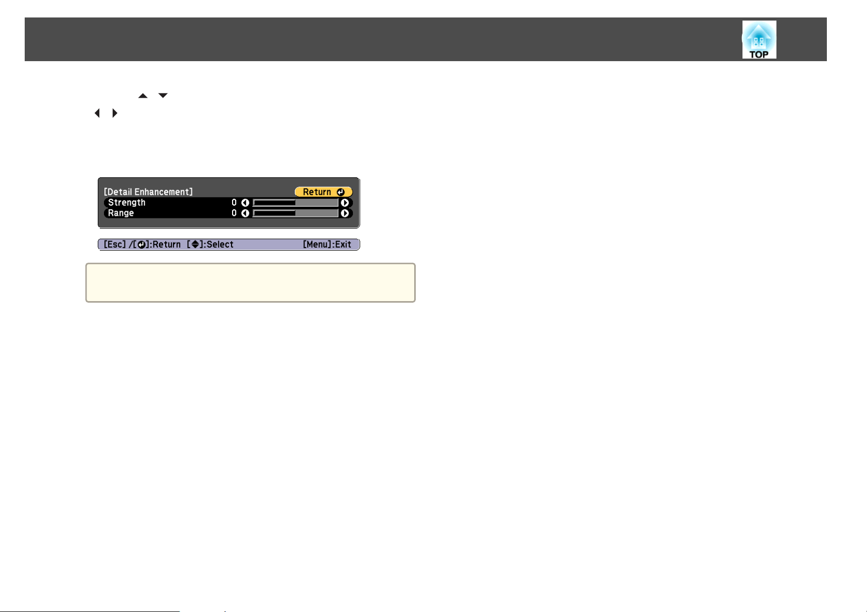
Adjusting Projected Images
85
b
c
Use the [ ][ ] buttons to select the item, and then use the
[
][ ] buttons to make the adjustments.
Strength: The larger the value, the more the contrast is enhanced.
Range: The larger the value, the wider the range of detail
enhancement becomes.
Depending on the image, a highlight may be noticeable at the
a
Press the [Esc] button to return to the previous screen.
border between colors. If this bothers you, set a smaller value.
Page 86

Useful Functions
This section describes the Multi-Projection, Split Screen, Memory, Schedule, and Security functions.
Page 87
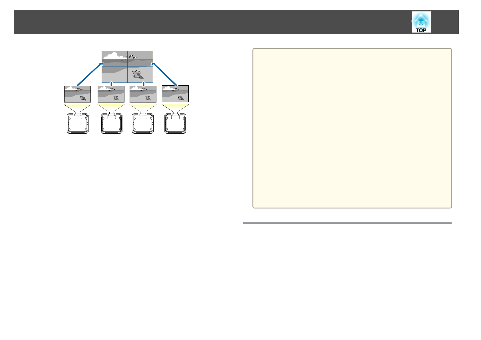
Multi-Projection Function
You can setup up to 15 projectors to project one large and wide image.
You can adjust the difference of brightness and color tone between each
projected image to create a seamless screen.
a
Set 4K Enhancement to Off.
We recommend setting the focus, zoom, and lens shift at least 20
minutes after you start the projection, because images are not stable
right after turning on the projector.
If the values for Geometry Correction are large, the image position
adjustment for overlapping images becomes difficult.
The Test Pattern can be displayed to adjust the projection status
without connecting video equipment.
"Displaying the Test Pattern" p.36
s
If you project a dot by dot image that can be projected without
being enlarged or reduced, you can make adjustments precisely.
When Run Periodically is set to On in Light Source Calibration,
calibration is automatically performed, and colors adjusted using
multi-projection may change. Set this to Off to maintain the
projected image as it is.
s Reset - Light Source Calibration - Run Periodically p.163
If you perform Screen Matching regularly, make sure you execute
Screen Matching after performing Light Source Calibration. If there
are still differences in the color, set Run Periodically to Off in Light
Source Calibration.
87
Adjustment Procedure
Adjusting automatically online
The arrangement for all projectors (Tiling) and adjustments for the images
(Edge Blending) are performed automatically using the projector set as the
master projector.
You can automatically correct distortion and overlapping areas in multiple
projected images by using the tiling assist function in Epson Projector
Professional Tool, and automatically correct images projected in a stack.
s
"Using Tiling Function of Geometry Correction Assist" p.100
Page 88

Multi-Projection Function
s
"Using the Stacking Function of Geometry Correction Assist" p.101
Advance preparation
(1) Connect to the network
- Connect all projectors to a network hub using LAN cables.
- Set the DHCP to On for all projectors, or check that IP addresses have been
assigned.
s Network - Network Configuration - Wired LAN - IP
Settings p.158
(2) Set an ID for the master projector and the remote control.
s "Set the projector ID" p.43
(3) Set Sleep Mode to Off
s Extended - Operation - Sleep Mode p.147
(3) Unify the brightness and tint of the images
s "Screen Matching" p.95
(4) Splice the images to create one, large image
s "Displaying a Scaled Image" p.98
Adjusting manually offline
Adjust the images from all projectors manually.
Advance preparation
Set an ID for all projectors and the remote controls.
s
"Set the projector ID" p.43
88
Adjusting projected images individually
(1) Unify the size of the images
s "Adjusting the Image Size" p.39
(2) Adjust the orientation and position of the image
s "Installation Settings" p.34
"Adjusting the Position of the Projected Image (Lens Shift
s
Adjustment)" p.37
(3) Fine tune the focus and distortion of the image
s "Correcting the Focus" p.40
s "Point Correction" p.72
Combining multiple projected images
(1) Set the arrangement of the images.
s "Performing tiling automatically" p.89
(2) Adjust the edges of the images
s "Edge Blending" p.91
s "Black Level" p.93
Adjusting projected images individually
(1) Unify the size of the images
s "Adjusting the Image Size" p.39
(2) Adjust the orientation and position of the image
s "Installation Settings" p.34
"Adjusting the Position of the Projected Image (Lens Shift
s
Adjustment)" p.37
(3) Fine tune the focus and distortion of the image
s "Correcting the Focus" p.40
s "Point Correction" p.72
Combining multiple projected images
(1) Set the arrangement of the images.
s "Performing tiling manually" p.90
(2) Adjust the edges of the images
s "Edge Blending" p.91
"Black Level" p.93
s
Page 89
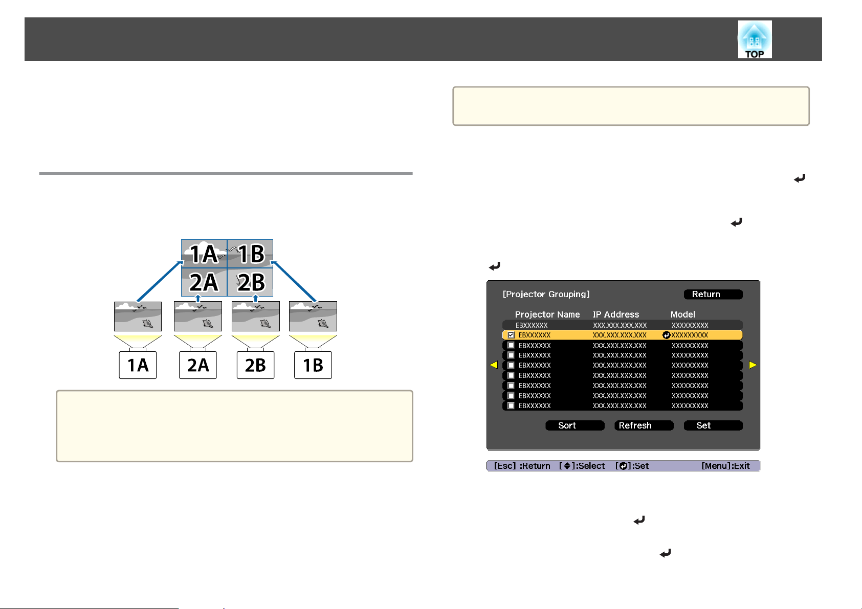
Multi-Projection Function
89
(3) Unify the brightness and tint of the images
s "Color Matching" p.97
(4) Splice the images to create one, large image
s "Displaying a Scaled Image" p.98
Tiling
When using multiple projectors to create one large image, assign a
projection position to each projector.
a
a
b
c
d
Location setup is performed using the camera built into the front of
the projector. Do not block the camera or the projected images.
Press the [Menu] button while projecting.
Select Multi-Projection from Extended, and then press the [ ]
button.
Select Projector Grouping, and then press the [ ] button.
Select the projectors that will be used for tiling, and then press the
[
] button.
Before performing tiling, adjust the projected image so that it is a
a
Performing tiling automatically
Automatically sets the arrangement for the projectors being used. You can
make settings by operating only the master projector.
rectangle. Also, adjust the size and focus of the images.
s "Adjusting the Image Size" p.39
s "Correcting the Focus" p.40
e
(1) Select the projectors you want to use to enter a checkmark.
Select Refresh to update the list. Select Sort to sort the projector order.
(2)
Select Set, and then press the [
Select Tiling, and then press the [ ] button.
] button.
Page 90
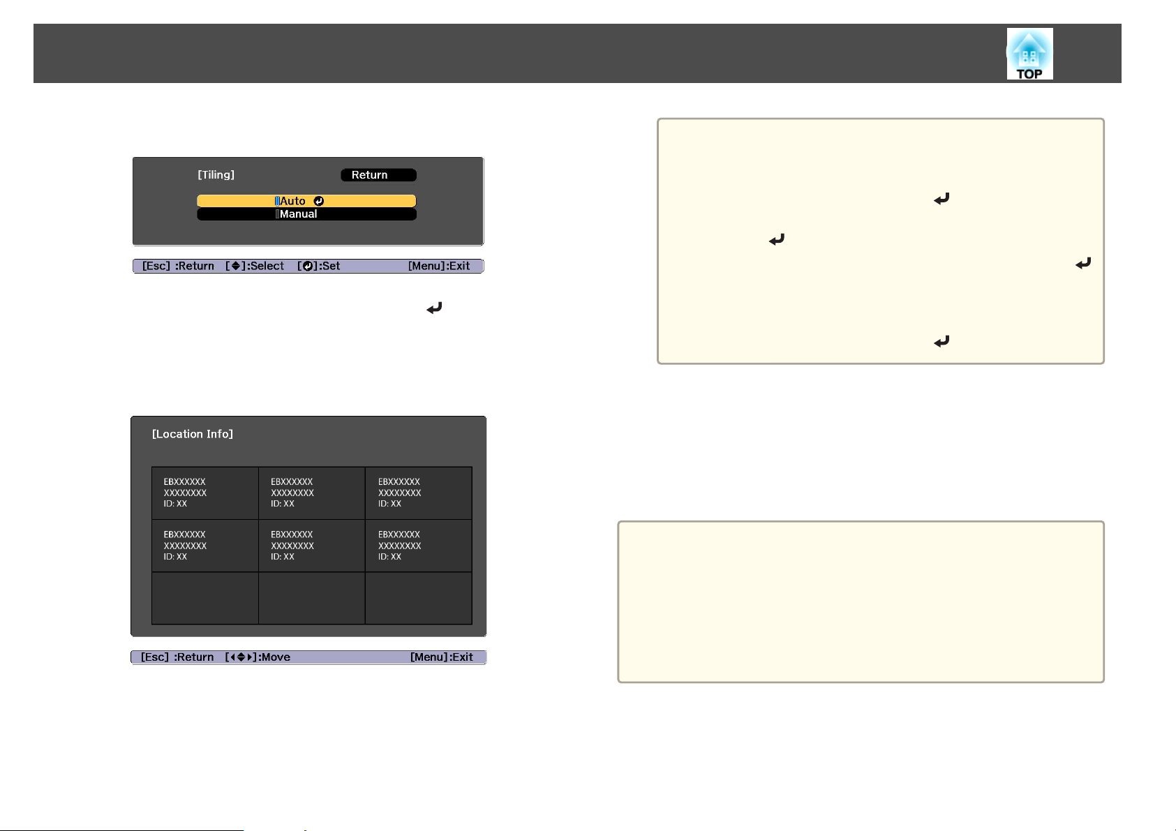
Multi-Projection Function
90
f
g
Select Tiling. Select Auto, and then press the [Esc] button.
Select Location Setup, and then press the [ ] button.
The image is positioned automatically.
When the message "Assign IDs to projectors that have been located.
Do you want to continue?" is displayed, select Yes.
When setup is complete, the following screen is displayed.
If the image is not located correctly, select Manual in step 6,
a
h
When tiling is complete, adjust any positional gaps and the tint of the
projected images.
s
Input the image signal to display the image.
s
Projected Image (Source Search)" p.60
"Adjusting projected images individually" p.88
and then follow the steps below to locate the image manually.
(1) Set Row and Column in Layout.
(2)
Select Set, and then press the [
(3)
Select the projector in Location Setup, and then press the
[
] button.
(4)
Select the position you want to locate, and then press the [
button.
(5) Repeat steps (3) and (4) to reposition the location of all
projectors.
(6)
Select Set, and then press the [
"Automatically Detecting Input Signals and Changing the
] button.
] button.
]
After tiling is complete, do not change the IP addresses or projector
a
Performing tiling manually
Manually arrange the images being projected for each projector.
names of the projectors. Otherwise the image will not be adjusted
automatically.
After tiling is complete, you can set each projector with one remote
control. Select the projector ID for the projector you want to set
with the remote control. You can check the projector ID in Tiling -
Location Info.
"Setting the remote control ID" p.44
s
Page 91
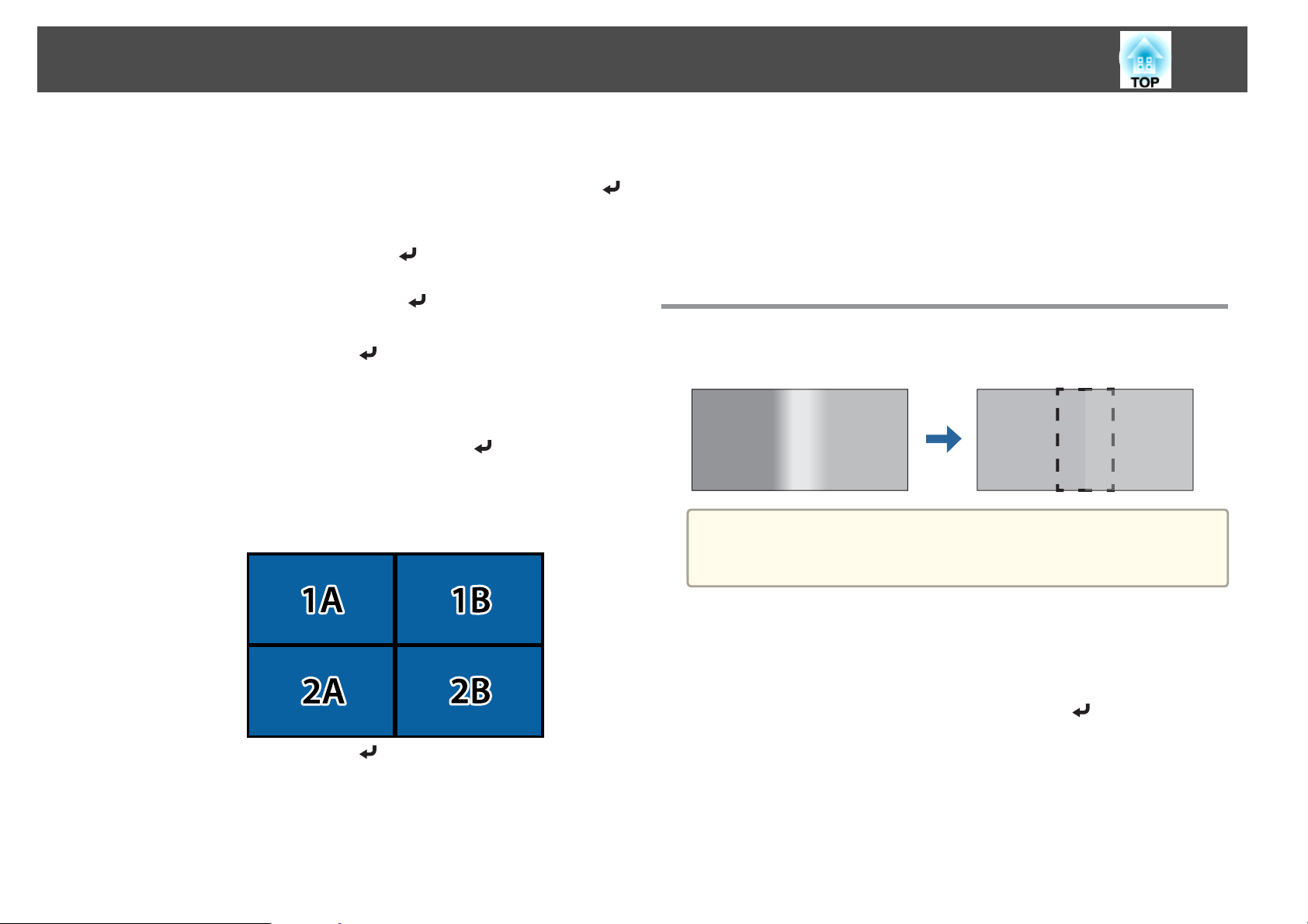
Multi-Projection Function
91
a
b
c
d
e
f
Press the [Menu] button while projecting.
Select Multi-Projection from Extended, and then press the [ ]
button.
Select Tiling, and then press the [ ] button.
Select Layout, and then press the [ ] button.
(1) Set the number of projectors in Row and Column.
(2)
Select Set, and then press the [
Repeat steps 1 to 4 for each projector to be used for tiling.
Select Location Setup, and then press the [ ] button.
(1) Set the positions of the projected images in Row Order and Column
Order.
Row Order: Place screens from top to bottom in the order of 1, 2, 3.
Column Order: Place screens from left to right in the order of A, B, C.
] button.
h
When tiling is complete, adjust any positional gaps and the tint of the
projected images.
s
Input the image signal to display the image.
s
"Automatically Detecting Input Signals and Changing the
Projected Image (Source Search)" p.60
"Adjusting projected images individually" p.88
Edge Blending
You can fine tune the overlapping areas to make seamless screen.
Before performing edge blending to raise the precision of adjustments,
a
press the [Color Mode] button on the remote control, and then set
Color Mode to Multi-Projection.
g
(2)
Select Set, and then press the [
Repeat step 6 for each projector.
a
Press the [Menu] button while projecting.
Select Multi-Projection from Extended.
b
Select Edge Blending, and then press the [ ] button.
c
The following screen is displayed.
] button.
Page 92
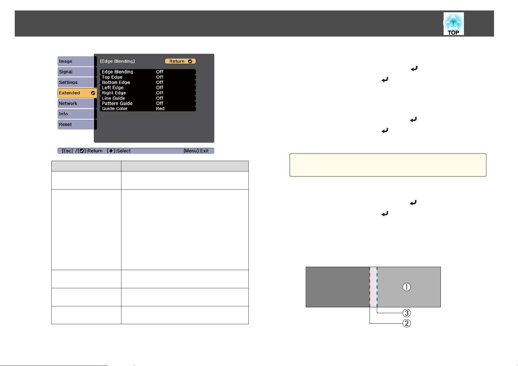
Multi-Projection Function
92
Submenu Function
Edge Blending
Top Edge/Bottom
Edge/Left Edge/Right
Edge
Set to On to activate Edge Blending. Set to Off
when not projecting from multiple projectors.
Blending: Set to On to activate Edge Blending
towards your settings, and the blend range will be
shaded.
Blend Start Position: Displays blending start
position as a red line, and adjusts at the level of one
pixel.
Blend Range: Adjusts the range to be shaded.
Adjustment is possible at the level of one pixel. The
maximum range is 45% of the resolution.
Blend Curve: Adjusts how to apply shading.
d
e
f
g
Turn on Edge Blending.
(1)
Select Edge Blending, and then press the [
(2)
Select On, and then press the [
(3) Press the [Esc] button.
Set Guide Display to On.
(1)
Select Guide Display, and then press the [
(2)
Select On, and then press the [
(3) Press the [Esc] button.
If the guide is not clear, you can change the color of the guide
a
Set Pattern Guide to On.
(1)
(2)
(3) Press the [Esc] button.
Set Top Edge, Bottom Edge, Left Edge, or Right Edge according
to the parts of the image that are overlapped.
The following shows how to set screen (1) as an example.
in Guide Color.
Select Pattern Guide, and then press the [
Select On, and then press the [
] button.
] button.
] button.
] button.
] button.
] button.
Line Guide
Pattern Guide
Guide Color
Set to On to display a guide on the Edge Blending
setting range.
Set to On to display a lattice pattern to match the
position of the Edge Blending setting range.
Select a combination of guide colors from the six
provided.
Page 93
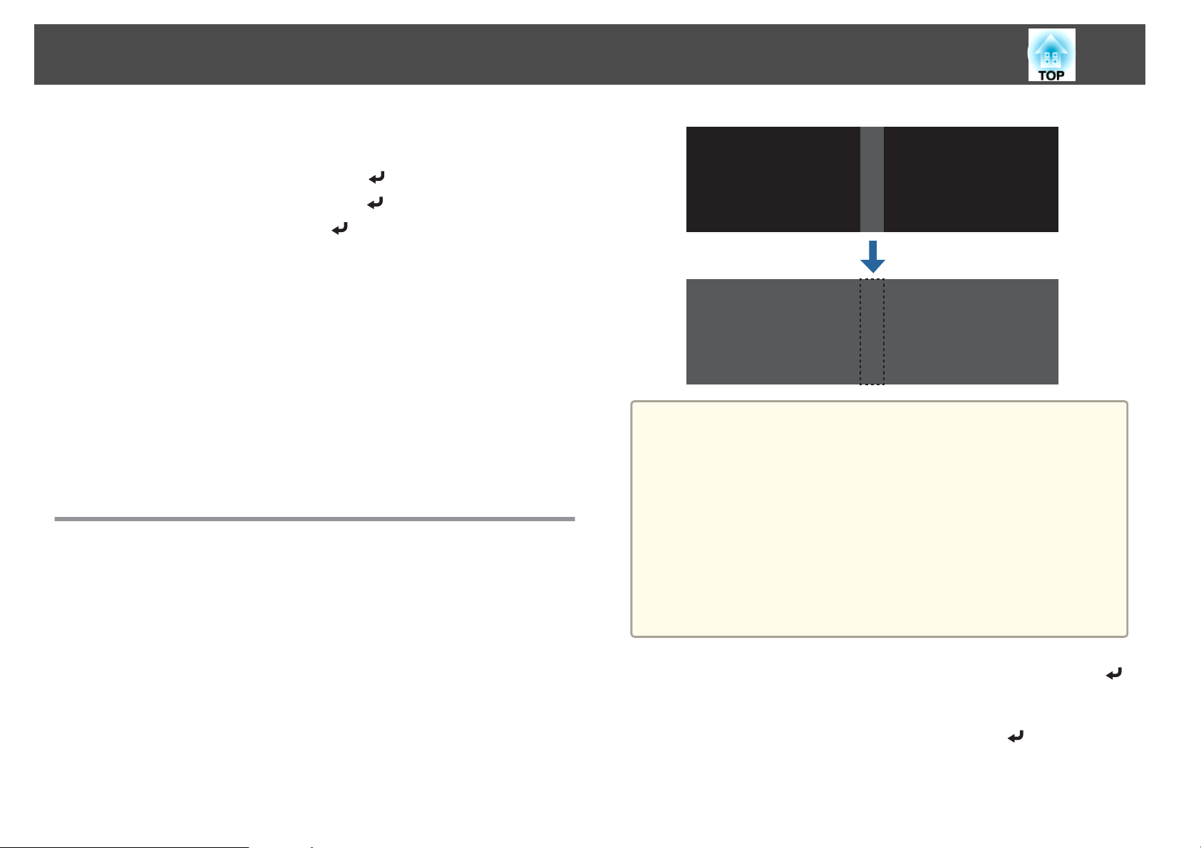
Multi-Projection Function
In the example above, you need to adjust the Left Edge because you
can see the overlapping areas on the left side of the image (1).
93
h
(1)
Select Left Edge, and then press the [
(2)
Select Blending, and then press the [
(3)
Select On, and then press the [
(4) Press the [Esc] button.
(5) In Blend Start Position, align the blending start position with the edge (2)
of the image.
(6) Press the [Esc] button.
(7) In Blend Range, adjust the range (3) to be shaded.
The value for when the overlapped range and the guide are in the same
position is the best.
(8) In Blend Curve, adjust how to apply shading.
(9) Press the [Esc] button.
After the settings are complete, set Line Guide and Pattern Guide
to Off to finish.
] button.
] button.
] button.
Black Level
When a black image is displayed, only areas where the images overlap
stands out. The black level function allows you to match the brightness and
tone for areas where the images do not overlap with areas where the images
overlap, to make the difference less noticeable.
a
You cannot perform Black Level when Edge Blending is set to Off
or no edge position has been selected.
You cannot adjust the Black Level when a test pattern is displayed.
If the Geometry Correction value is large, you may not be able to
adjust correctly.
The brightness and tone may differ in areas where the images
overlap as well as in other areas even after performing black level
adjustment.
When auto adjustment starts for Screen Matching, the settings for
Color Adjustment are automatically adjusted.
s "Automatically correct the brightness and tint for multiple
projectors" p.96
a
b
Select Black Level from Multi-Projection, and then press the [ ]
button.
Select Color Adjustment, and then press the [ ] button.
The areas are displayed based on the settings for Top Edge/Bottom
Edge/Right Edge/Left Edge.
Page 94
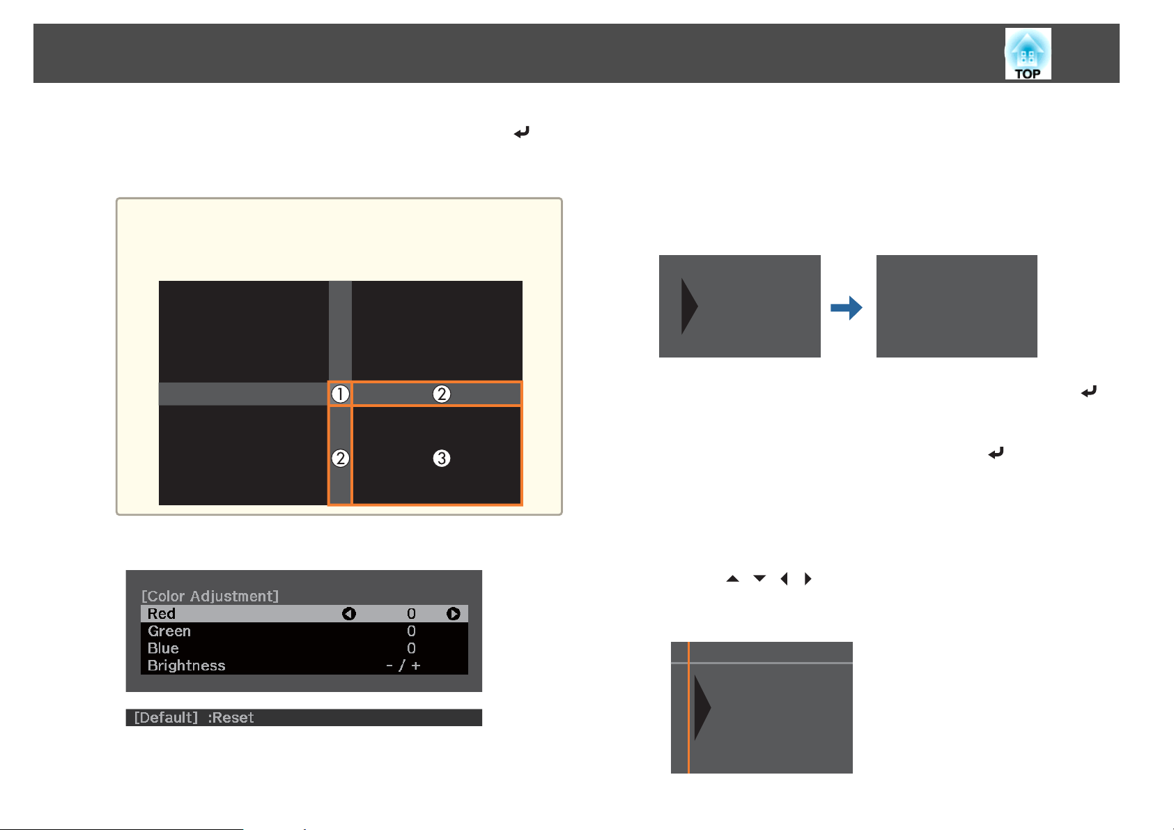
Multi-Projection Function
94
c
d
Select the area you want to adjust, and then press the [ ]
button.
The selected area is displayed in orange.
When multiple screens are overlapping, adjust based on the area
a
Adjust the black tone and brightness.
with the most overlap (the brightest area). In the illustration
below, first align (2) with (1), and then adjust so that (3) aligns
with (2).
f
To complete the adjustment, press the [Menu] button.
Area Correction
If there are areas where the color does not match after adjusting the Black
Level, adjust individually in Area Correction.
a
Select Black Level from Area Correction, and then press the [ ]
button.
Select Start Adjustments, and then press the [ ] button.
b
Boundary lines that indicate areas where images overlap are
displayed.
The boundary lines are displayed based on the settings for Top
Edge/Bottom Edge/Right Edge/Left Edge.
c
Use the [ ][ ][ ][ ] buttons to select a boundary line of the
area you want to adjust.
The selected line is displayed in orange.
e
Repeat steps 3 and 4 as needed to adjust any remaining parts.
Page 95
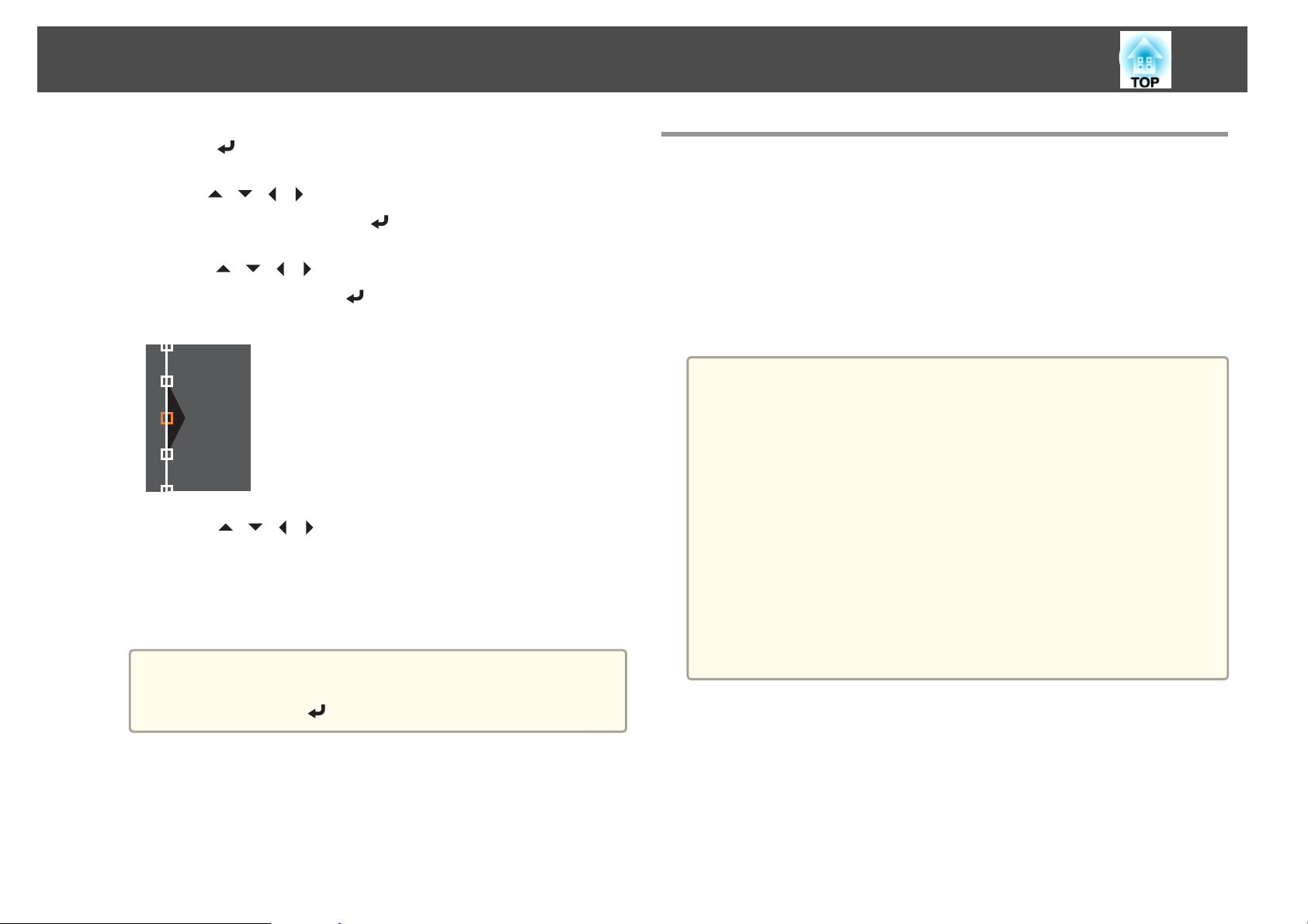
Multi-Projection Function
95
d
e
f
g
Press the [ ] button to confirm the selection.
Use the [ ][ ][ ][ ] buttons to adjust the boundary line
positions, and then press the [
Press the [ ][ ][ ][ ] buttons to select the point you want to
move, and then press the [
The selected point is displayed in orange.
Press the [ ][ ][ ][ ] buttons to move the point.
To continue to move another point, press the [Esc] button to return
to step 6, and then repeat steps 6 and 7.
To adjust another boundary line, press the [Esc] button until the
screen for selecting a boundary line from step 3 is displayed.
To return Black Level to its default value, press the [Esc]
a
button to return to the screen from step 1, select [Reset], and
then press the [
] button.
] button.
] button.
Screen Matching
Adjust the tint and brightness for multiple projectors.
When projectors are connected to a network, the tint and brightness for
multiple projectors are automatically adjusted based on the darkest
projector.
When projectors are not connected to a network, or if auto adjustment
does not work, you can adjust the tint and brightness for all projectors
manually.
We recommend performing Screen Matching at least 20 minutes
a
after turning on the projector or canceling the shutter function.
To increase the accuracy of adjustments, we recommend darkening
the room while projecting images and then making adjustments.
Perform the following on the master projector before starting
adjustments.
- Set the Color Mode to Multi-Projection with the remote
control's [Color Mode] button.
- Press the [Shutter] button on the remote control to release the shutter.
- Adjust the following items on the Image menu as necessary.
Brightness, Contrast, Color Saturation, Tint, White Balance, Advanced
"Image Menu" p.141
s
- Set the brightness of the projected image.
s "Setting the Brightness" p.75
h
To complete the adjustment, press the [Menu] button.
Page 96
Multi-Projection Function
96
When a particularly dark projector is included in the group, the
a
brightness is automatically adjusted according to the dark projector.
Use the following method to select the master projector.
- When you want the image to be as bright as possible:
Set the Light Source Mode for all projectors to Normal or Custom -
Brightness Level - 100%. For the master projector, select a projector
whose color and brightness you want to use as the standard.
- When you want to match to a specific brightness:
Set the projector with the darkest projected image as the master
projector, and then use Light Source Mode - Custom - Brightness
Level to adjust it so that it has a specific brightness.
s Settings - Brightness Settings - Light Source Mode, Brightness
Level p.143
When there are large differences in the brightness for each projector
due to aging light sources, perform Screen Matching again.
See the following if Screen Matching does not work correctly.
s "Automatic adjustments are not performed correctly" p.206
Operating conditions for auto adjustment functions
The auto adjustment functions for Screen Matching are enabled when the
following conditions are met.
The screen surface is flat and not skewed or warped
Using a matte white diffusion screen
The projection size for each projector is 100 to 300 inches
The projected image after tiling is rectangular
There are no gaps between projected images (or part of the images
overlap)
The projector is setup parallel to the projection surface
The blend width for edge blending is 15 to 45%
All projectors have the following model numbers
EB-L30002U/EB-L30000U
Auto adjustment is not available when using the following lenses.
a
ELPLR05, ELPLL09, and ELPLL10
After auto adjustment, lens shift may not work for some lenses.
"Adjusting the Position of the Projected Image (Lens Shift
s
Adjustment)" p.37
Automatically correct the brightness and tint for multiple projectors
The brightness and tint for the arranged images are adjusted automatically
based on the darkest projector.
Check the following before starting auto adjustment.
a
- The projector is connected to the network
-The Location Setup for the projector has already been set
-The Brightness Level is set to the maximum for all projectors
s Settings - Brightness Settings - Light Source Mode, Brightness
Level p.145
Auto adjustment is performed using the camera built into the front
of the projector. Do not block the camera or the projected images.
The time necessary for auto adjustment varies according to the
location and number of projectors and can take up to approximately
17 minutes.
Settings are auto adjusted for Brightness Settings, Black Level (Color
Adjustment only), and Blend Curve.
After making automatic adjustments, Color Uniformity and Color
Matching are returned to their defaults.
After performing auto adjustment, Light Source Control is set to
Off.
You can schedule this from Schedule Settings.
Page 97
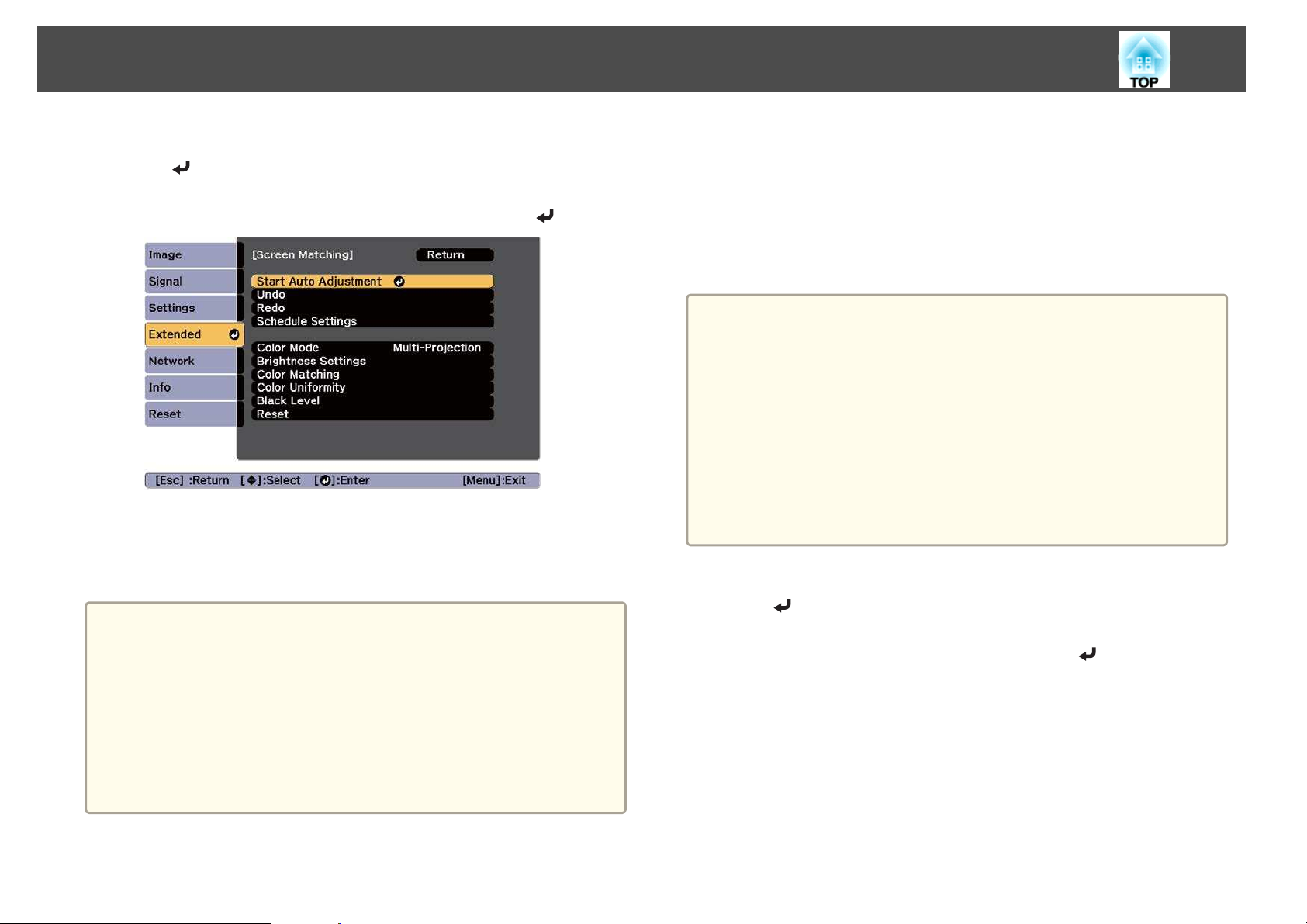
Multi-Projection Function
97
a
b
a
Select Screen Matching from Multi-Projection, and then press
the [
Select Start Auto Adjustment, and then press the [ ] button.
When a message is displayed, select Yes. The adjustment pattern is
displayed, and adjustment starts. If the projected image is displayed
before the adjusting, the procedure is complete.
] button.
See the following if an error occurs.
s "Automatic adjustments are not performed correctly" p.206
To return to the status before auto adjustment, select Undo. When
you select Redo after selecting Undo, it returns the image to the
status after auto adjustment.
If the amount of blend width or lens shift is too large, blend curve
may not be corrected properly. Adjust the Blend Curve manually.
s "Edge Blending" p.91
To return Screen Matching to its default value, select Reset.
Color Matching
You can fine tune the color balance and brightness from black to white for
each color tone.
When the projectors are not connected to a network, or if you want to
adjust manually after the automatic adjustments, perform the following
steps on all projectors.
We recommend that you reset the following settings on the Image
a
a
menu to display the adjustment screen at the appropriate brightness
and color.
Brightness
Contrast
Color Saturation
Tint
White Balance (Color Temp., G-M Correction, Offset R, Offset G,
Offset B, Gain R, Gain G, Gain B)
Gamma
RGBCMY
Select Screen Matching from Multi-Projection, and then press
the [
Select Color Matching, and then press the [ ] button.
] button.
b
Page 98
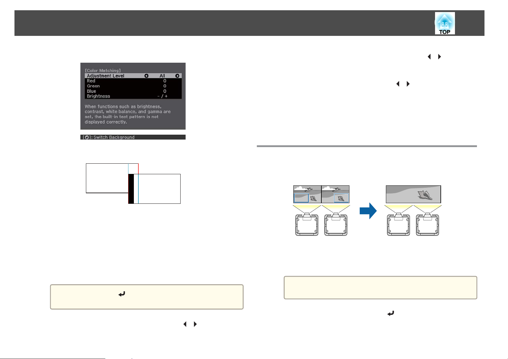
Multi-Projection Function
98
The following screen is displayed.
Half of the overlapped area is displayed in black so that it is easy to
check the edge of the image.
Adjustment Level: There are eight levels from All, white, through
gray, and up to black. When you select All, you can adjust the color
for each color in Adjustment Level 2 to 8 at the same time. (Once
the red, blue, and green values are at their maximum or minimum
position at any level, you cannot make any further adjustments.)
Select Adjustment Level 1 to 8 to adjust each level individually.
Red, Green, Blue: Adjusts the tone for each color.
Brightness: Adjusts the image brightness.
Whenever the [ ] button is pressed, the screen changes
a
between the projected image and the adjustment screen.
d
e
Select Red, Green, or Blue, and then press the [ ][ ] buttons to
adjust the color tone.
Select Brightness, and then use the [ ][ ] buttons to adjust the
brightness.
Return to step 2 and adjust each level.
f
g
Press the [Esc] button to return to the previous screen.
Displaying a Scaled Image
A section of the image is cropped and displayed. This allows you to create
one large image by combining images projected from multiple projectors.
Project the image, and then press the [Menu] button.
a
b
Select Multi-Projection from Extended.
You can also perform the same operation from Scale in
a
Signal.
c
c
Select Scale, and then press the [ ] button.
Select Adjustment Level, and then use the [ ][ ] buttons to set
the adjustment level.
Page 99
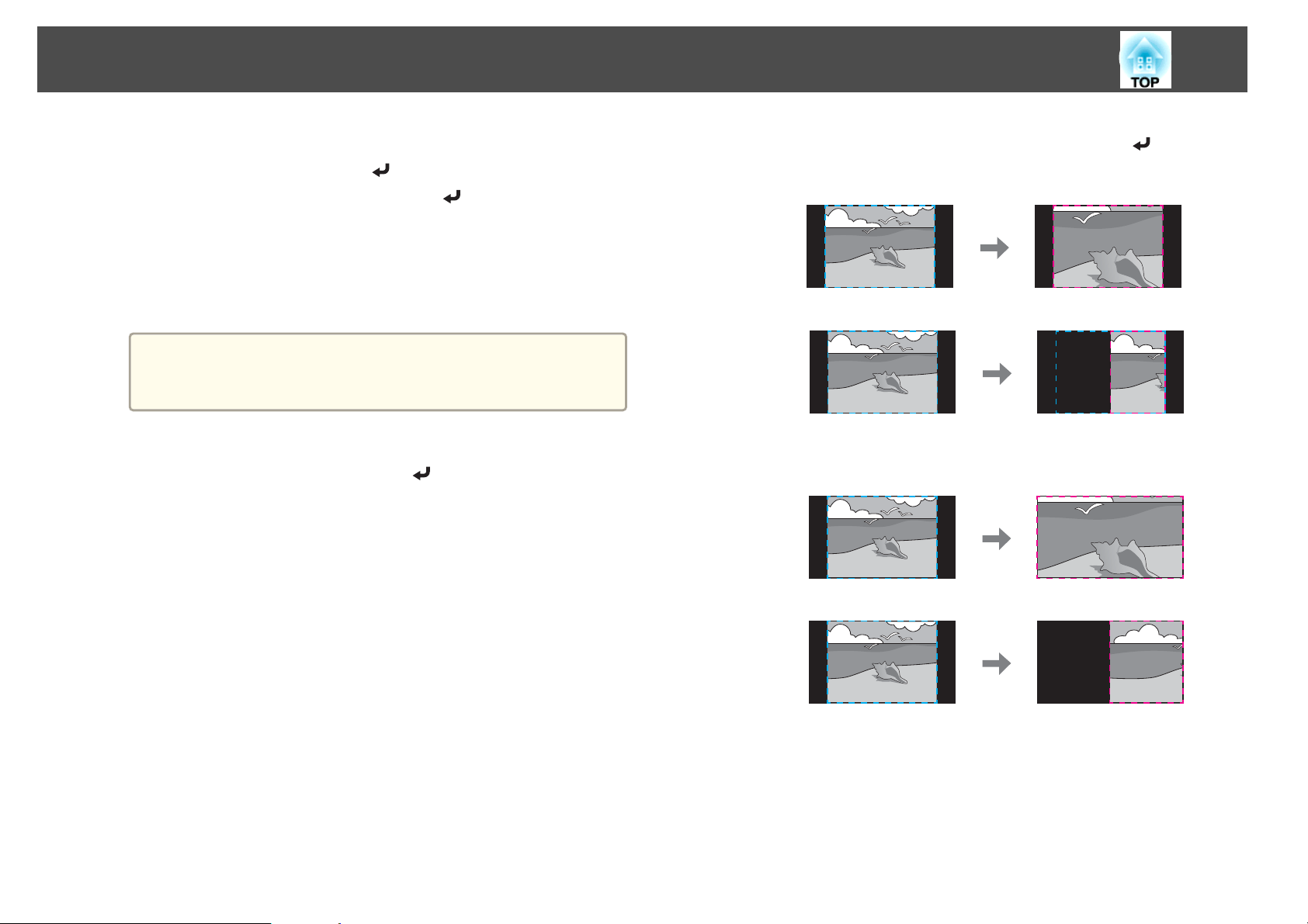
Multi-Projection Function
99
d
e
Turn on Scale.
(1)
Select Scale, and then press the [
(2)
Select Auto or Manual, and then press the [
Auto: Automatically adjusts the clipped area according to the adjustment
values in Edge Blending and Tiling. After selecting Auto, you can then
select Manual to fine tune adjustments from step 6 onwards.
Manual: Allows you to adjust the clipped area manually.
(3) Press the [Esc] button to return to the previous screen.
If auto adjustment does not work for the clipped image, adjust
a
Set Scale Mode.
(1)
the aspect ratio, and then select Auto.
s "Changing the Aspect Ratio of the Projected Image" p.78
Select Scale Mode, and then press the [
] button.
] button.
] button.
(2)
Select Zoom Display or Full Display, and then press the [
Zoom Display: Adjusts according to the image currently displayed.
Enlarge
Move
Full Display: Adjusts according to the projector's panel size (the
maximum area in which an image can be displayed).
Enlarge
] button.
Move
(3) Press the [Esc] button to return to the previous screen.
Page 100
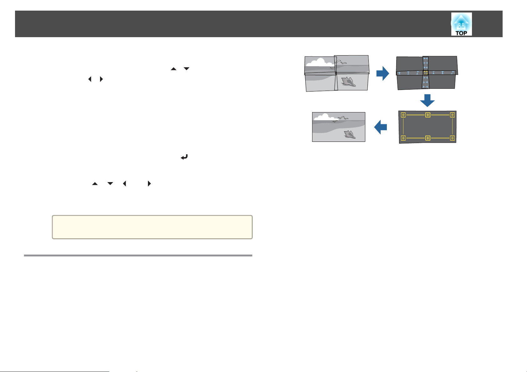
Multi-Projection Function
100
f
g
Adjust the scale.
Select the adjustment method with the [
using the [
maximum magnification of 10)
-+: Enlarges or reduces an image horizontally and vertically at the
same time.
Scale Vertically: Enlarges or reduces an image vertically.
Scale Horizontally: Enlarges or reduces an image horizontally.
The image is clipped and adjusted.
(1)
Select Clip Adjustment, and then press the [
If you select Clip Range, the range and coordinates of the image that the
projector will project is displayed.
(2)
Use the [
Adjust the coordinates and size of each image while viewing the screen.
(3) Press the [Menu] button to finish making settings.
a
][ ] buttons. (Minimum magnification of 0.5 to
], [ ], [ ], and [ ] buttons to scroll the image.
You can check the displayed area after clipping for the entire
image from Clip Range.
][ ] buttons, then adjust
] button.
You can run this feature from Epson Projector Professional Tool (version
1.20 or later). Download the software from the following Web site.
http://www.epson.com
Operating conditions for auto adjustment functions
The tiling function of geometry correction assist works under the following
conditions.
The screen surface is flat and not skewed or warped
Using Tiling Function of Geometry Correction Assist
By using the projector's built-in camera and the Edge Blending feature, you
can create a seamless image by automatically adjusting the pixel position in
overlapping areas of the image.
Using a matte white diffusion screen
The illuminance ratio of the screen when projecting an all-white screen
and when projecting an all-black screen is 8:1 or more
The projection size for each projector is 100 to 500 inches
(When projecting onto a screen surface with an illuminance of 40 lux or
lower with the Light Source Mode set to Normal)
The projected image after tiling is rectangular
Parts of all projected images are overlapping
The projector is setup parallel to the projection surface
The blend width for edge blending is 15 to 43%
 Loading...