

Page 1
SERVICE MANUAL
Color Inkjet Printer
EPSON STYLUS CX3500/CX3650/CX3600/
CX4500/CX4600
SEOT04-004
Page 2

Notice
V All rights reserved. No p art of t his manual may be reprod uced, stored i n a ret rieval sy stem, or t ransmit ted in any form or by a ny means el ectroni c,
mechanical, photocopying, or otherwise, without the prior written permission of SEIKO EPSON CORPORATION.
V The contents of this manual are subject to change witho ut notice.
V All effort have been made to ensure the accuracy of the contents of this manual. However, should any errors be detected, SEIKO EPSON would
greatly appreciate being informed of them.
V The above not withstanding SEIKO EPSON CORPORATION can assume no responsibility for any errors in this manual or the consequences
thereof.
EPSON is a registered trademark of SEIKO EPSON CORPORATION.
General Notice:Other product names used herein are for identif ic ation purp ose only and may be trademarks or registe red tr ademarks of thei r respec-
tive owners. EPSON disclaims any and all rights in those marks.
Copyright © 2004 SEIKO EPSON CORPORATION.
TPCS Quality Assurance Dept.
Page 3

PRECAUTIONS
Precautionary notations throughout the text are categorized relative to 1)Personal injury and 2) damage to equipment.
DANGER Signals a precaution which, if ignored, could result in serious or fatal personal injury. Great caution should be exercised in
performing procedures preceded by DANGER Headings.
WARNING Signals a precaution which, if ignored, could result in damage to equipment.
The precautionary measures itemized below should always be observed when performing repair/maintenance procedures.
DANGER
1. ALWAYS DISCO NNECT THE PRODUCT FROM THE POWER SOURCE AND PERIPHERAL DEVICES PERFORMING ANY
MAINTENANCE OR REPAIR PROCEDURES.
2. NO WORK SHOULD BE PERFORMED ON THE UNIT BY PERSONS UNFAMILIAR WITH BASIC SAFETY MEASURES AS DICTATED
FOR ALL ELECTRONICS TECHNICIANS IN THEIR LINE OF WORK.
3. WHEN PERFORMING TESTING AS DICTATED WITHIN THIS MANUAL, DO NOT CONNECT THE UNIT TO A POWER SOURCE UNTIL
INSTRUCTED TO DO SO. WHEN THE POWER SUPPLY CABLE MUST BE CONNECTED, USE EXTREME CAUTION IN WORKING ON
POWER SUPPLY AND OTHER ELECTRONIC COMPONENTS.
4. WHEN DISASSEMBLING OR ASSEMBLING A PRODUCT, MAKE SURE TO WEAR GLOVES TO AVOID INJURIER FROM METAL PARTS
WITH SHARP EDGES.
WARNING
1. REPAIRS ON EPSON PRODUCT SHOULD BE PERFORMED ONLY BY AN EPSON CERTIFIED REPAIR TECHNICIAN.
2. MAKE CERTAIN THAT THE SOURCE VOLTAGES IS THE SAME AS THE RATED VOLTAGE, LISTED ON THE SERIAL NUMBER/
RATING PLATE. IF THE EPSON PRODUCT HAS A PRIMARY AC RATING DIFFERENT FROM AVAILABLE POWER SOURCE, DO NOT
CONNECT IT TO THE POWER SOURCE.
3. ALWAYS VERIFY THAT THE EPSON PRODUCT HAS BEEN DISCONNECTED FROM THE POWER SOURCE BEFORE REMOVING OR
REPLACING PRINTED CIRCUIT BOARDS AND/OR INDIVIDUAL CHIPS.
4. IN ORDER TO PROTECT SENSITIVE MICROPROCESSORS AND CIRCUITRY, USE STATIC DISCHARGE EQUIPMENT, SUCH AS
ANTI-STATIC WRIST STRAPS, WHEN ACCESSING INTERNAL COMPONENTS.
5. REPLACE MALFUNCTIONING COMPONENTS ONLY WITH THOSE COMPONENTS BY THE MANUFACTURE; INTRODUCTION OF
SECOND-SOURCE ICs OR OTHER NONAPPROVED COMPONENTS MAY DAMAGE THE PRODUCT AND VOID ANY APPLICABLE
EPSON WARRANTY.
Page 4

About This Manual
This manual describes basic functions, theory of electrical and mechanical operations, maintenance and repair procedures of the printer. The instructions and
procedures included herein are intended for the experienced repair technicians, and attention should be given to the precautions on the preceding page.
Manual Configuration
This manual consists of six chapters and Appendix.
CHAPTER 1.PRODUCT DESCRIPTIONS
Provides a general overview and specifications of the
product.
CHAPTER 2.OPERATING PRINCIPLES
Describes the theory of electrical and mechanical
operations of the product.
CHAPTER 3.TROUBLESHOOTING
Describes the step-by-step procedures for the
troubleshooting.
CHAPTER 4.DISASSEMBLY / ASSEMBLY
Describes the step-by-step procedures fo r disassembling
and assembling the product.
CHAPTER 5.ADJUSTMENT
Provides Epson-approved methods for adjustment.
CHAPTER 6.MAINTENANCE
Provides preventive maintenance procedures and the
lists of Epson-approved lubricants and adhesives
required for servicing the product.
CHAPTER 7.APPENDIX
Provides the following additional information for
reference:
• Connector pin assignments
• Electric circuit boards components layout
• Electrical circuit boards schematics
• Exploded diagram & Parts List
Symbols Used in this Manual
Various symbols are used throughout this manual either to provide
additional information on a specific topic or to warn of possible danger
present during a procedure or an action. Be aware of all symbols when
they are used, and always read NOTE, CAUTION, or WARNING
messages.
ADJUSTMENT
REQUIRED
CAUTION
CHECK
PO INT
W ARNING
Indicates an operating or maintenance procedure, practice
or condition that, if not strictly observed, could result in
injury or loss of life.
Indicates an operating or maintenan ce pr ocedure, practi ce,
or condition that, if not strictly observed, could result in
damage to, or destruction of, equipment.
May indicate an operating or maintenance procedure,
practice or condition that is necessar y to accomplish a task
efficiently. It may also provid e additional information that is
related to a specific subject, or comment on the results
achieved through a previous action.
I.ndicates an operating or maintenance procedure, practice
or condition that, if not strictly obser ved, could result i n injury
or loss of life.
Indicates that a particular task must be carried out
according to a certain standard after disassembly and
before re-assembly, otherwise the quality of the
components in question may be adversely affected.
Page 5

Revision Status
Revision Issued Date Description
A 2004/8/18 First Release
NOTE: Any illustrations or photos of the printer without a card slot are based on the Stylus CX3500/3600/CX3650.
Page 6

CONTENTS
Chapter 1 PRODUCT DESCRIPTION
1.1 Overview........ ....... ...... ...... ....... ...... ....... ...... ....... ...... ....... ........................ 9
1.1.1 F e atures ................................. ....... ...... ....... ...... ....... ...... ....... ...... ..... 9
1.2 Specifications ...................................................................................... 11
1.2.1 Printer specifications ..................................................................... 11
1.2.2 Scanner specifications ..... ...... ....... ...... ....... ...... ....... ...... ....... ...... ... 19
1.2.3 Common........................................................................................ 20
1.3 Interface................................................................................................ 22
1.3.1 USB Interface................................................................................ 22
1.3.2 Standard Card Slots
(only for Stylus CX4500/CX4600) ........................................................... 23
1.4 Stand-alone Copy................................................................................ 25
1.4.1 Basic Specifications ...................................................................... 25
1.4.2 Copy Speed................................................................................... 26
1.4.3 Configuration for copying .............................................................. 26
1.4.4 Relation between original and copy .............................................. 27
1.5 Memory Card Print
(only for Stylus CX4500/CX4600) .............................................................. 30
1.5.1 Basic Specifications ...................................................................... 30
1.5.2 Functions....................................................................................... 31
1.5.3 Index Sheet ................................................................................... 33
1.5.4 Layout and Paper Type, Paper Size ............................................. 36
1.5.5 Options.......................................................................................... 36
1.5.6 Trimming Function......................................................................... 36
1.5.7 Assignment Rules for Photo Frame Numbers and Rota tion ......... 37
1.5.8 Layout Drawings.. ...... ....................................... ....... ...... ....... ...... ... 38
1.5.9 Relation between Paper Type and Quality.................................... 40
1.6 Control Panel ....................................................................................... 41
1.6.1 Buttons .......................................................................................... 41
1.6.2 Indicators....................................................................................... 41
1.6.3 Operations..................................................................................... 43
1.6.4 Printer Condition and Panel Status............................................... 47
1.6.5 Memory Functions......................................................................... 50
1.6.6 Printer Initialization........................................................................ 51
Chapter 2 OPERATING PRINCIPLES
2.1 Overview .............................................................................................. 53
2.2 Printer Mechanism ................................................... ...... ....... ...... ....... . 53
2.2.1 Printer Mechanism ........................................................................ 53
2.2.2 Print Head ..................................................................................... 54
2.2.3 Carriage Mechanism..................................................................... 56
2.2.4 Paper Loading/Feeding Mechanism ............................................. 58
2.2.5 Ink System Mechanism................................................................. 63
2.2.6 Ink Sequence ................................................................................ 66
2.3 Scanner Mechanism............................................................................ 68
2.3.1 Scanner Carriage Mechanism....................................................... 68
2.4 Electrical Circuit Operating Principles.............................................. 70
2.4.1 PSB/PSE Board ............................................................................ 71
2.4.2 C571/577 Main Board ................................................................... 72
Chapter 3 TROUBLESHOOTING
3.1 Overview .............................................................................................. 80
3.2 Error Indications and Fault Occurrence Causes.............................. 80
3.3 Troubleshooting.................................................................................. 85
3.3.1 Superficial Phenomenon-Based Troubleshooting....................... 105
Chapter 4 DISASSEMBLY AND ASSEMBLY
4.1 Overview ............................................................................................ 114
4.1.1 Precautions ................................................................................. 114
4.1.2 Tools ........................................................................................... 115
Page 7

4.1.3 Work Completion Check.............................................................. 116
4.2 Caution regarding assembling/disassembling of the Printer
Mechanism, and how to ensure of quality on re-assembled product. 117
4.3 Disassembly....................................................................................... 118
4.3.1 Document Cover ......................................................................... 119
4.3.2 Paper Support Assy. ................................................................... 120
4.3.3 Stacker Assy. .............................................................................. 120
4.3.4 Scanner Unit........ ...... ....... ...... ....... ...... ....................................... . 121
4.3.5 Panel Unit.................................................................................... 126
4.3.6 Housing Upper ............................................................................ 127
4.3.7 Print Head ................................................................................... 128
4.3.8 Printer Mechanism ...................................................................... 130
4.3.9 PS Board Unit.............................................................................. 133
4.3.10 Waste Ink Pads ......................................................................... 134
4.3.11 Main Board Unit......................................................................... 136
4.3.12 ASF Unit.................................................................................... 141
4.3.13 Holder Shaft Unit....................................................................... 143
4.3.14 CR Guide Frame ....................................................................... 146
4.3.15 CR Motor................................................................................... 147
4.3.16 PF Motor.................................................................................... 148
4.3.17 Carriage Unit ............................................................................. 149
4.3.18 Paper Guide Upper Unit............................................................ 152
4.3.19 Front Frame............................................................................... 153
4.3.20 EJ Frame Unit ........................................................................... 154
4.3.21 Ink System Unit ......................................................................... 156
4.3.22 Paper Guide Front Unit ............................................................. 157
4.3.23 PG Sensor................................................................................. 158
4.3.24 PF Roller Unit............................................................................ 159
Chapter 5 ADJUSTMENT
5.2.6 Ink charge ................................................................................... 165
5.2.7 Input Head ID.............................................................................. 165
5.2.8 Input PF roller manufacture code................................................ 165
5.2.9 Top margin adjustment ............................................................... 165
5.2.10 Head angular adjustment.......................................................... 166
5.2.11 Bi-D adjustment......................................................................... 167
5.2.12 PW adjustment.......................................................................... 167
5.2.13 First dot position adjustment ..................................................... 168
5.2.14 CR motor heat protection control .............................................. 168
5.2.15 Print check pattern .................................................................... 168
5.3 Adjustment Except Adjustment Program ....................................... 170
5.3.1 PG adjustment ............................................................................ 170
5.3.2 PF Scale Sensor positioning adjustment .................................... 173
Chapter 6 MAINTENANCE
6.1 Overview ............................................................................................ 175
6.1.1 Cleaning...................................................................................... 175
6.1.2 Service Maintenance................................................................... 175
6.1.3 Lubrication................................................................................... 177
Chapter 7 APPENDIX
7.1 Connector Summary................................... ...... ....... ...... ....... ...... ...... 182
7.1.1 Major Component Unit ................................................................ 182
7.2 Component Layout............................................................................ 188
7.3 Exploded Diagram............................................................................. 192
7.4 Parts List............................................................................................ 197
7.5 Electrical Circuits.................... ....... ...... ....... ...... ....... ...... ....... ...... ...... 199
5.1 Overview............................................................................................. 162
5.1.1 Required Adjustment................................................................... 162
5.2 Adjustment by using adjustment program ..................................... 164
5.2.1 EEPROM Data Copy................................................................... 164
5.2.2 Waste ink pad counter................................................................. 164
5.2.3 Destination setting....................................................................... 165
5.2.4 Initialize PF deterioration offset................................................... 165
5.2.5 Disenable PF deterioration offset................................................ 165
Page 8

PRODUCT DESCRIPTION
CHAPTER
Page 9
EPSON Stylus CX3500/CX3600/CX3650/CX4500/CX4600 Revision A
1.1 Overview
The major features of EPSON color inkjet dot matrix printer EPSON Stylus CX3500/
CX3600/CX3650/CX4500/CX4600 are:
1.1.1 Features
V Printer functions
As a printer, this unit achieves high-quality output at high speed on plain paper,
and uses new pigment inks for improved light fastness, water fastness, gas
fastness, rubbing fastness. It includes the following features.
T Maximum print resolution: 2880 (H) x 1440 (V) dpi
T Separate ink cartridge for each color
T ASF (Auto Sheet Feeder) holds up to 100 cut sheets (64g/m
T Border-free printing with EPSON specialty media is provided
T Reduced noise level
T Fast and thick draft mode with the combination of real black and composite
black
V Scanner functions
Use of a CIS sensor means no warm-up period is requ i red, which makes scanning
more convenient and allows for a more compact scanner.
Additional features include the following.
T Maximum optical resolution 600 x 1200 dpi
T Scan gradations 48 bits (input), 24 bits (output)
2
)
V Stand-alone copy functions
It benefits from using a more recently developed type of ink which enables photoquality copies to be made not only on special media but even on plain p aper. On ly
the basic copy functions are provided for easy operation.
T Paper size can be selected from 2 or 3 options.
Table 1-1. Paper size
Paper size Model
Letter/4"x6" Stylus CX4600
A4/10x15 Stylus CX3500/ CX3600/CX3650/C X4500
T Paper type can be selected from 2 options, plain paper or photo paper, which
also defines copy quality.
T Enlarge / Reduce factor can be selected from 2 options, actual size (100%) or
“Fit to page”.
T Copy margin is automatically selected from 3 options, related to paper type
and paper size. 3mm, “Small Margins Copy”, “Border Free Copy”
T Fast and thick draft mode with the combination of real black and composite
black
T Copy functions can be directly alternated from memory card print functions,
by operation panel. (Only for Stylus CX4500/CX4600)
V Card reader functions (only for Stylus CX4500/CX4600)
This unit includes memory card slots that support CompactFlash, SmartMedia,
Memory Stick, Memory Stick PRO, Micro Drive, SD Memory Card, and xDPicture Card standards.
V Memory card print functions (only for Stylus CX4500/CX4600)
This unit can print images from the memory card in memory card slots in standalone mode.
The memory card print features are as follows.
T Supports “Index sheet printing” whereby images can be selected simply by
marking an index sheet. Selecting images is easy-just check the desired
images and then scan the index sheet.
T Memory card print functions can be directly alternated from copy functions,
by operation panel.
PRODUCT DESCRIPTION Overview 9
Page 10
EPSON Stylus CX3500/CX3600/CX3650/CX4500/CX4600 Revision A
V Scan functions
This unit provides scan mode so that data can be scanned and transferred to a
connected computer or to e-mail via application software like the EPSON SMART
PANEL.
V Simultaneous use of functions
Printer functions and scanner functions are independent and can therefore be
operated simultaneously from a connected computer.
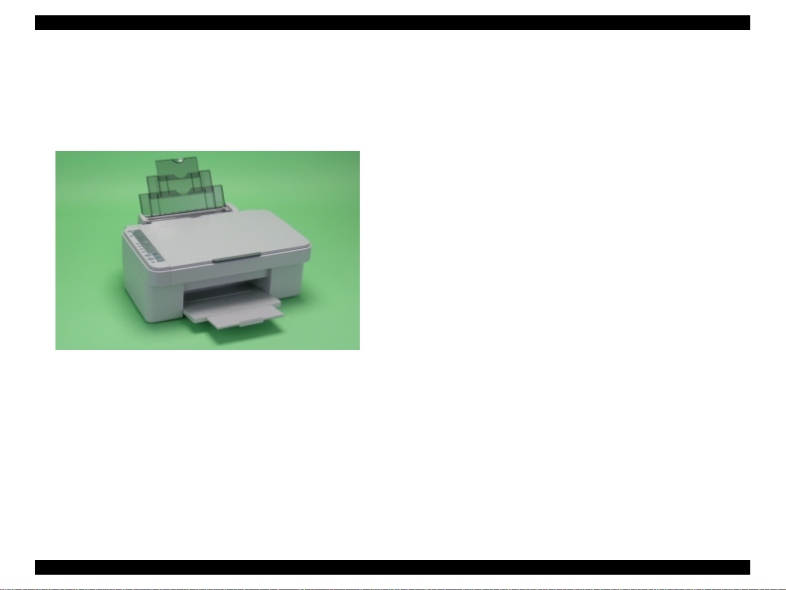
Figure 1-1. Product’s external view
V Easy operation panel
The unit has a simple operation panel equipped with 10 buttons including power
button, LEDs including 7 segment LED and provides basic functions only for
easy operation.
* Card slot model only. (9 buttons for the model without card slot)
V Exterior de sign
Use of a CIS scanner engine has enabled a more compact design.
Also, this unit has operation panel on the left side, which becomes more distinctive
but still easier to use.
PRODUCT DESCRIPTION Overview 10
Page 11
EPSON Stylus CX3500/CX3600/CX3650/CX4500/CX4600 Revision A
1.2 Specifications
1.2.1 Printer specifications
This section covers specifications of the printer.
1.2.1.1 Physical Specification
V Weight
T Stylus CX3500/CX3600/CX3650 : 6.52kg (without the ink cartridges)
T Stylus CX4500/CX4600 : 6.6kg (without the ink cartridges)
V Dimension (Including rubber feet)
T Printing : 430mm (W) x 500mm (D ) x 2 80mm (H)
T Storage : 430mm (W) x 344mm (D ) x 1 70mm (H )
1.2.1.2 Printing Specification
V Print Method
T On demand i nk jet
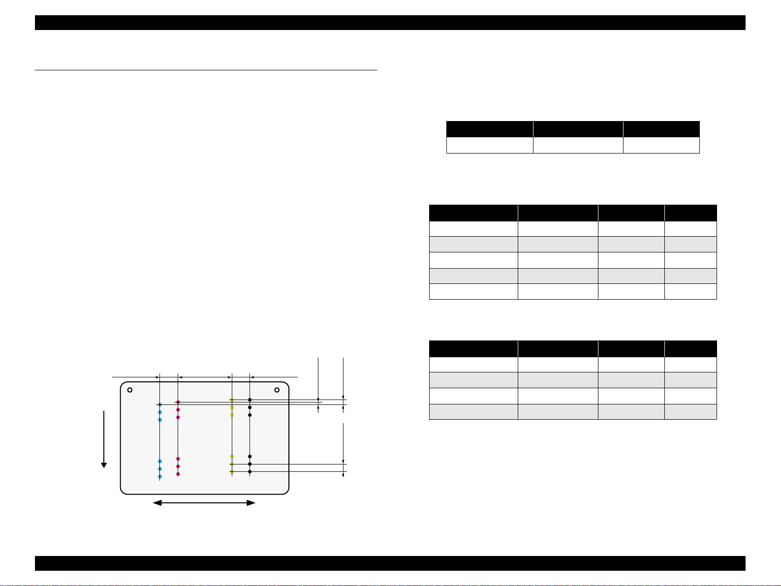
V Nozzle Configuration
T Monochrome 90 nozzles
T Color 90 nozzles x 3 (Cyan, Magenta, Yellow)
Paper Feed Direction
2.822
(40/360inch)
#A90
#A89
#A88
A row B row C row D row
#A3
#A2
#A1
8.467
(120/360inch)
#B90
#C90
#C89
#B89
#C88
#B88
#B3
#B2
#B1
#C3
#C2
#C1
2.822
(40/360inch)
#D90
#D89
#D88
#D3
#D2
#D1
BlackCyan Magenta Yellow
0.1411
0.107055
(1/360inch)
0.2117
V Print Direction
T Bi-directional minimum distance printing (with logic seeking)
V Print Speed & Printable Columns
Table 1-2. Character mode
Character pitch Printable columns CR speed
10 CPI (Pica) 80 285 CPS*
Note "* ": CPS: Characters/Second
This speed is when using normal dot printing mode.
Table 1-3. Graphics mode (standard)
Horizontal resolution Printable area Max. dot count CR speed
360dpi* 209.8mm (8.26") 2976 285cps
360dpi 209.8mm (8.26") 2976 285cps
720dpi 209.8mm (8.26") 5952 285cps
1440dpi 209.8mm (8.26" ) 11904 285cps
2880dpi 209.8mm (8.26") 23808 285cps
Note "*": Draft Printing
Table 1-4. Graphics mode (border-free printing)
Horizontal resolution Printable area Max. dot count CR speed
360dpi* 215.05mm (8.46") 3048 285cps
720dpi 215.05mm (8.46") 6096 285cps
(2/360inch)
1440dpi 215.05mm (8.46") 12192 285cps
2880dpi 215.05mm (8.46") 24384 285cps
Note "* ": Except Draft Printing
(3/360inch)
V Control Code
T ESC/P Raster command
T EPSON Remote command
Carriage Moving Direction
Figure 1-2. Nozzle configuration
PRODUCT DESCRIPTION Specifications 11
Page 12
EPSON Stylus CX3500/CX3600/CX3650/CX4500/CX4600 Revision A
V Internal fonts
T Character code : Alphanumeric with expanded graphics (PC437)
ASCII, 20H to 7FH only
T Fonts : EPSON original fonts
Alphanumeric font: Courier
V Input buffer size
T 32 Kbytes
1.2.1.3 Paper Feed Specifications
V Paper feed method
Friction feed, using one ASF (Auto Sheet Feeder)
V Paper path
Top feed, front out
V Paper feed rates
T 203.2mm/sec (8.0inch/sec)
: high quality mode, 25.4-mm feed
T 294.64mm/sec (11.6inch/sec)
: high speed mode, continuous feed
V CR interval
Programmable in 0.0176mm (1/1440inch) steps
1.2.1.4 Paper Support
V Cut sheets
Paper size
A4 210mm 297mm
A5 148mm 210mm
A6 105mm 148mm
B5 182mm 257mm
Letter
Legal
Executive
Half Letter
5"x8"
8"x10"
User
defined
89-215.9mm 89-1117.6mm
Dimensions
Width Length
215.9mm
(8.5")
215.9mm
(8.5")
184.2mm
(7.25")
139.7mm
(5.5")
127mm
(5")
203.2mm
(8")
Table 1-5. Cut sheets
Thickness Weight Paper type
279.4mm
(11")
355.6mm
(14")
266.7mm
(10.5")
215.9mm
(8.5")
203.2mm
(8")
254mm
(10")
0.08-0.11mm
64-90g/m
(17-24(lb))
2
Plain paper
Recycled paper
CAUTION
T Poor quality paper may reduce print quality and cause paper
jams or other problems. If you encounter problems, switch to a
higher grade of paper.
T It is necessary that there is no wrinkle, nap, tear, fold, so on in
the form.
T The curve of form must be 5mm or below.
T Use paper under normal conditions
• Temperature 15 to 25°C (59 to 77°F)
• Humidity 40 to 60% RH
PRODUCT DESCRIPTION Specifications 12
Page 13
EPSON Stylus CX3500/CX3600/CX3650/CX4500/CX4600 Revision A
V Postcards V Envelopes
Table 1-6. Postcards
Paper size
Postcard 100mm 148mm
Return postcard set 200mm 148mm
CAUTION
T Use paper under normal conditions
• Temperature 15 to 25°C (59 to 77°F)
• Humidity 40 to 60% RH
Dimensions
Width Length
T It is necessary that there is no wrinkle, nap, tear, fold, so on in
the form.
T The curve of form must be 5mm or below.
T As for the going and returning postcard, don't use the one with a
fold in the center.
Paper type
Government -s ta ndard postcard
Table 1-7. Enve lopes
Paper size
1
No.10 *
1
DL *
1
C6 *
220x132 *
Tall No.3 *
Tall No.4 *
Western No.1 *
Western No.2 *
Western No.3 *
Western No.4 *
1
2
2
1
1
1
1
Note *1: Check that the flap is on the long edge and can be folded.
*2: Check that the flap is on the short edge and can not be fo ld ed.
CAUTION
T Use paper under normal conditions
Dimensions
Thickness Weight Paper type
Width Length
241.3mm
(9.5")
104.8mm
(4.125")
220mm 110mm
162mm 114mm
220mm 132mm
120mm 235mm
N/A
90mm 205mm
120mm 176mm
114mm 162mm
98mm 148mm
105mm 235mm
• Temperature 15 to 25°C (59 to 77°F)
• Humidity 40 to 60% RH
75-90g/m
(20-24(lb))
75-100g/m
(20-27(lb))
T Poor quality paper may reduce print quality and cause paper
jams or other problems. If you encounter problems, switch to a
higher grade of paper.
T It is necessary that there is no wrinkle, nap, tear, fold, so on in
the form.
T Don't use the adhesive envelopes.
T Don't use sleeve insert envelopes and cellophane window
envelopes.
Bond paper
Air mail
2
PPC
Craft paper
New Kent paper
2
PRODUCT DESCRIPTION Specifications 13
Page 14
EPSON Stylus CX3500/CX3600/CX3650/CX4500/CX4600 Revision A
V Exclusive papers
Quality: EPSON Exclusive paper
Transparency printing is only available at normal temperature.
T Stylus CX4600
Table 1-8. Exclusive papers
Item Size
Glossy Photo Paper *
Matte Paper Heavy
Weight *
DURABrite Ink Glossy
Photo Paper
Double Sided Matte
Paper *
Note "*": Not supported with stand-alone functions of copy and memory card print.
CAUTION
T Use paper under normal conditions.
Letter 215.9 279.4
4"x6" 101.6 152.4
Letter 215.9 279.4
8"x10" 203.2 254
Letter 215.9 279.4
4"x6" 101.6 152.4
Letter 215.9 279.4 0.25 178
• Temperature 15 to 25°C (59 to 77°F)
• Humidity 40 to 60% RH
Width
(mm)
Length
(mm)
Thickness
(mm)
0.23 188
0.23 167
0.21 206
T Poor quality paper may reduce print quality and cause paper
jams or other problems. If you encounter problems, switch to a
higher grade of paper.
T It is necessary that there is no wrinkle, nap, tear, fold, so on in
the form.
T The curve of form must be 5mm or below.
Weight
2
(g/m
T Stylus CX3500/CX3600/CX3650/CX4500
Table 1-9. Exclusive papers
Item Size
Photo Paper * A4 210 297 0.23 188
A4 210 297
)
Photo Quality Ink Jet
Paper *
Matte Paper Heavy
Weight *
DURABrite Photo
Paper
Premium Semigloss
Photo Paper *
Archival Matte Paper * A4 210 297 0.25 189
Double Sided Matte
Paper *
Note "*": Not suppo rted with stand-alone functions of copy and memory card print.
CAUTION
T Use paper under normal conditions.
• Temperature 15 to 25°C (59 to 77°F)
• Humidity 40 to 60% RH
A6 105 148
5"x8" 127 203.2
8"x10" 203.2 254
A4 210 297
8"x10" 203.2 254
A4 210 297
10cmx15cm 101.6 152.4
A4 210 297 0.27 250
A4 210 297 0.25 178
Width
(mm)
Length
(mm)
Thickness
(mm)
0.13 102
0.23 167
0.21 206
Weight
2
(g/m
)
T Poor quality paper may reduce print quality and cause paper
jams or other problems. If you encounter problems, switch to a
higher grade of paper.
T It is necessary that there is no wrinkle, nap, tear, fold, so on in
the form.
T The curve of form must be 5mm or below.
PRODUCT DESCRIPTION Specifications 14
Page 15
EPSON Stylus CX3500/CX3600/CX3650/CX4500/CX4600 Revision A
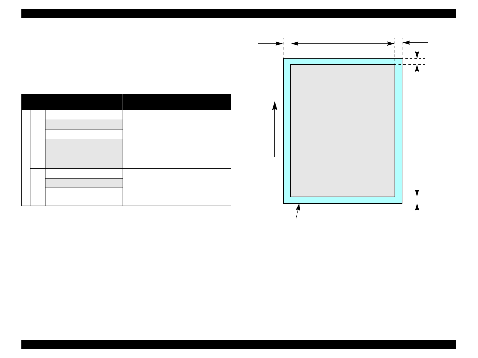
1.2.1.5 Printing Area
V Cut sheet (standard printing)
T Printable area
The print quality is guaranteed for the print area above the 3 mm bottom
margin. For paper width (PW) and paper length (PL), refer to “1.2.1.4 Paper
Support” (p.12).
Refer to the following table. As for each margin area, refer to Figure 1-3
(p.15).
Table 1-10. Applicable paper/Printing area
Paper type
A4
A5
A6
B5
Letter
Legal
Executive
Cut sheets
Half Letter
5"x8"
8"x10"
User defined
Postcard
Post
cards
Return postcard set
Photo Paper
Photo Quality In k Jet Paper
Matte Paper Heavy Weight
DURABrite Photo Paper
Premium Semigloss Photo Paper
Exclusive pa pers
CX3650/CX4500
Archival Matte Paper
Stylus CX3500/CX3 600/
Double Sided Matte Paper
Left
margin
3 mm
(0.12")
3 mm
(0.12")
3 mm
(0.12")
Right
margin
3 mm
(0.12")
3 mm
(0.12")
3 mm
(0.12")
Top
margin
3 mm
(0.12")
3 mm
(0.12")
3 mm
(0.12")
Bottom
margin
3 mm
(0.12")
3 mm
(0.12")
3 mm
(0.12")
Paper type
Glossy Photo Paper
Matte Paper Heavy Weight
DURABrite Ink Glossy Photo
Paper
Stylus CX4600
Exclusive papers
Double Sided Matte Paper
LM
Paper Feed Direction
Figure 1-3. Printable area Cut sheet (standard printing)
Table 1-10. Applicable paper/Printing area
Left
margin
3 mm
(0.12")
Right
margin
3 mm
(0.12")
PW
Printable area
Top
margin
3 mm
(0.12")
RM
TM
BM
Bottom
margin
3 mm
(0.12")
PL
PRODUCT DESCRIPTION Specifications 15
Page 16
EPSON Stylus CX3500/CX3600/CX3650/CX4500/CX4600 Revision A
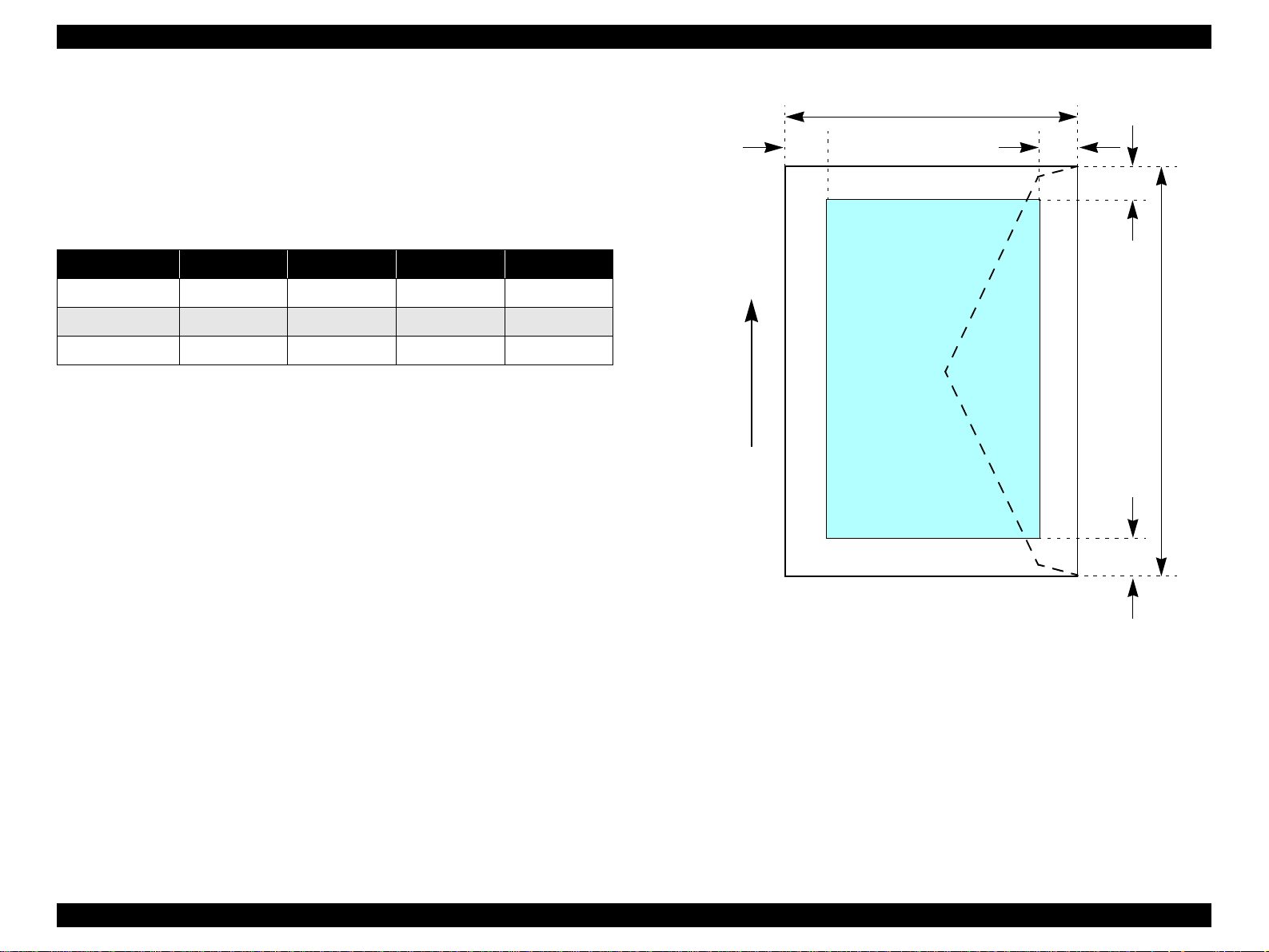
V Cut sheet (border-free printing)
T Printable area
For paper width (PW) and paper leng th (PL), refer to “1.2.1.4 Paper Support”
(p.12).
Refer to the following table. As for each overhang area, refer to Figure 1-4
(p.16).
Table 1-11. Applicable paper/Printing area
Paper type
Photo Paper
Matte Paper Heavy Weight
DURABrite Photo Paper
Premium Semigloss Photo Paper
CX3650/CX4500
Stylus CX3500/CX3 600/
Exclusive paper
Glossy Photo Paper
Matte Paper Heavy Weight
DURABrite Ink Glossy Photo
Paper
Stylus CX4600
Left
Overhang
2.5 mm
(0.09")
2.5 mm
(0.09")
Right
Overhang
2.5 mm
(0.09")
2.5 mm
(0.09")
Top
Overhang
3 mm
(0.12")
3 mm
(0.12")
Bottom
Overhang
5 mm
(0.2")
5 mm
(0.2")
LO ROPW
Paper size
Paper Feed Direction
TO
PL
BO
Printable area
Figure 1-4. Printable area for Cut sheet (border-free printing)
PRODUCT DESCRIPTION Specifications 16
Page 17
EPSON Stylus CX3500/CX3600/CX3650/CX4500/CX4600 Revision A
V Envelopes
T Printable area
For paper width (PW) and paper leng th (PL), refer to “1.2.1.4 Paper Support”
(p.12).
Refer to the following table. As for each margin area, refer to Figure 1-5
(p.17).
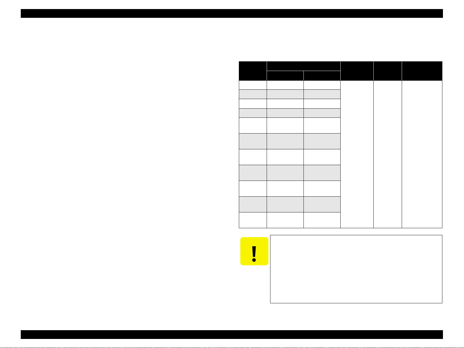
Table 1-12. Applicable paper/Printing area
Paper type Left Margin Right Margin Top Margin Bottom Margin
No.10 3mm (0.12") 3mm (0.12") 3mm (0.12") 20mm (0.79 ")
DL 3mm (0. 12") 3mm (0.12") 3mm (0.12") 20mm (0.79")
C6 3mm (0.12") 3mm (0.12") 3mm (0.12") 20mm (0.79")
PL
LM
RM
TM
Printable area
PW
Paper Feed Direction
BM
Figure 1-5. Printable area for envelopes
PRODUCT DESCRIPTION Specifications 17
Page 18
EPSON Stylus CX3500/CX3600/CX3650/CX4500/CX4600 Revision A
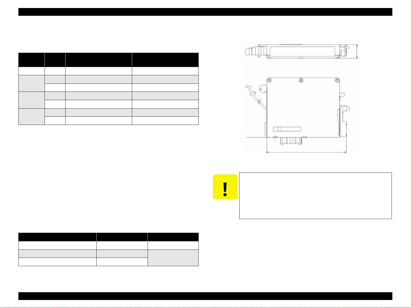
1.2.1.6 Ink Cartridge Specification
V Type/color : EPSON-brand special ink cartridges
Table 1-13. Ink Cartridge
Color Size
Black S size T0441 T0461
Cyan
Magenta
Yellow
Note "*": Except Stylus CX4600.
S size T0442 —
SS size T0452 * T0472
S size T0443 —
SS size T0453 * T0473
S size T0444 —
SS size T0454 * T0474
V Print Capacity
T Black Ink Cartridge : 400 pages/A4
T Color Ink Cartridge
• S size : 450 pages/A4 (360x720 dpi, 5% duty for each color)
• SS size : 260 pages/A4 (360x720 dpi , 5% duty for each color)
V Shelf life : After packing is opened, it is assumed 6 months, and
V Storage Temperature
Stylus CX3500/CX3600/
CX3650/CX4600
Stylus CX3500/CX4500
(ISO/IEC10561 Letter Pattern at 360x720 dpi)
380 pages/A4
(360x720 dpi, 5% duty)
assumes 2 years including this.
V Dimension : 12.7mm (W) x 73.46mm (D) x 55.25mm (H)
Base View
73.46mm
Figure 1-6. Ink cartridge
CAUTION
T The ink cartridge cannot be refilled.
T The ink cartridge that passes the expiration date should not be
used.
T The ink in the ink cartridge freezes when leaving it in the
environment of -16 °C or under. It takes 3 hours that the frozen
ink becomes usable when moving it from the environment of -20
°C to the environment of 25 °C.
12.7mm
Table 1-14. Storage Temperature
Situation Storage Temper ature Limit
o
When transported in individual boxes -30
When stored in individual boxes -30 oC to 40 oC
When installed in main unit -20 oC to 40 oC
C to 50 oC 10 days max. at 50 oC
1 month max. at 40 oC
PRODUCT DESCRIPTION Specifications 18
Page 19
EPSON Stylus CX3500/CX3600/CX3650/CX4500/CX4600 Revision A
1.2.2 Scanner specifications
This section covers specifications of the scanner.
1.2.2.1 Basic Specifications
V Product type : Flatbed color image scanner
V Scanning method : Scanning of fixed document wit h mobile scan head
V Sensor : CIS
V Maximum scan area : 8.5" x 11.7" (216 mm x 297 mm)
V Document sizes : A4 or US letter
V Max. effective pixels : 5,100 x 7,020 pixels (600 dpi)
V Resolution
T Main scan : 600 dpi
T Sub scan : 1200 dpi with Micro Step
V Scanning resolution : 50 to 4800 dpi (selectable in 1-dpi steps), 7200 dpi,
9600 dpi
V Gradations (pixel depth) : Each color pixel has 16-bit input and either 1-bit or 8-
bit output.
V Scanning speed : 600 dpi
T Color : Approx. 15 msec/line
1.2.2.3 Image scanning area
Table 1-15. Image scanning area
RW
(readable width)
216 mm (8.5") 1.5 mm ± 1 mm 297 mm (11.7") 1.5 mm ± 1 mm
OLM
(out-of-range left margin)
Original's top left alignment position
OLM
First pixel
Scan direction
RL
(readable length)
(out-of-range top margin)
a
RW
RLOTM
OTM
Original
(face down)
Scan bed
Scan area
T Monochrome : Approx. 5 msec/line
V Light source : RGB Three Color LED
Figure 1-7. Image scanning area
1.2.2.2 Detailed Specifications
V Control commands : ESC/I D7
V Gamma correction : Two user-defined levels
PRODUCT DESCRIPTION Specifications 19
Page 20
EPSON Stylus CX3500/CX3600/CX3650/CX4500/CX4600 Revision A
1.2.3 Common
1.2.3.1 Electric Specification
V Primary power input
Table 1-16. Primary power input
100-120V model 220-240V mo del
Rated power su pply volta ge (A CV) 100 ~ 120 220 ~ 240
Input voltage range (ACV) 90 ~ 132 198 ~ 240
0.4A
Rated current (A)
Rated frequency (Hz) 50 ~ 60
Input frequency range (Hz) 49.5 ~ 60.5
Power consumption (W)
(max. 0.6A w/ card slot model)
(max. 0.7A w/o card slot model)
Approx. 11W (w/ card slot model)
Approx. 12W (w/o ca rd slot model)
(Standalone copying, ISO10561 Lett er Patter, Plain
Paper - Text)
Approx. 2.5W (Lowe-power Mode/Sleep Mode)
Approx. 0.2W
(Power Off Mode)
0.2A (max. 0.3A)
Approx. 0.4W
(Power Off Mode)
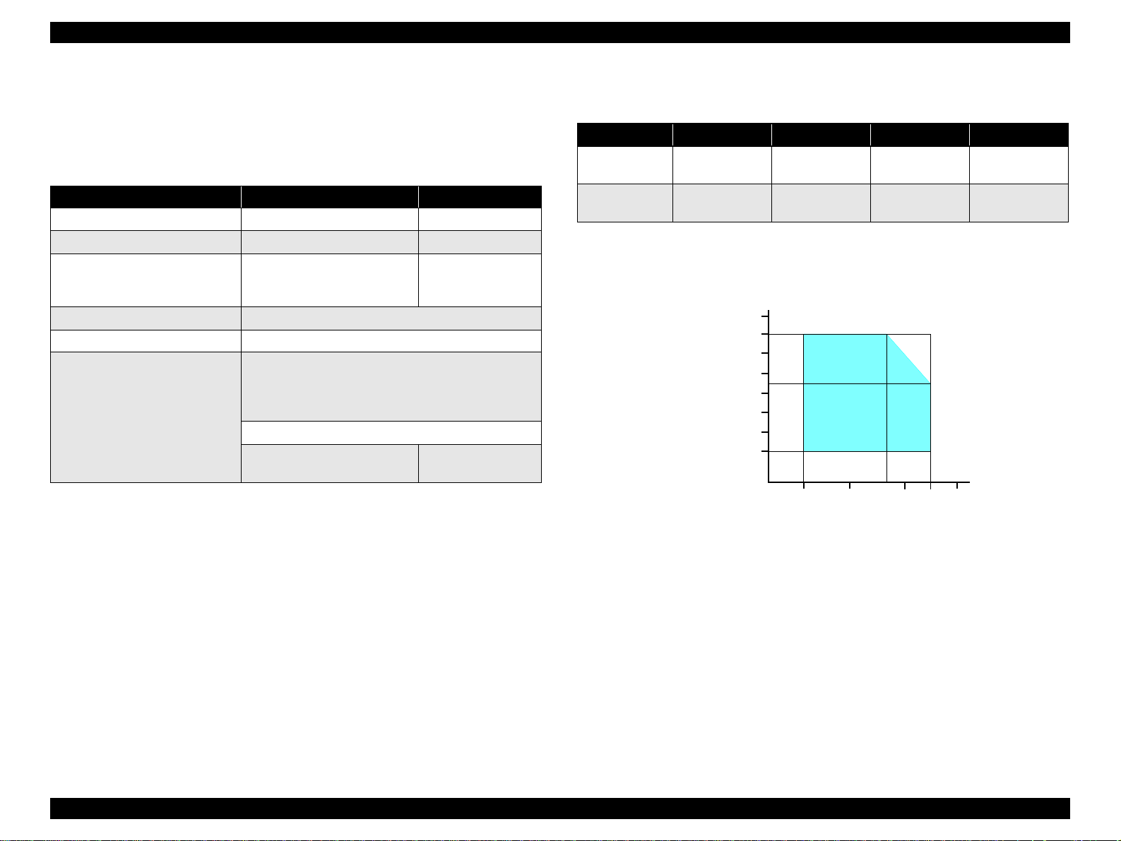
1.2.3.2 Environmental Performance
Table 1-17. Environmental Performance
Condition Temperature Humidity *
3
Operating 10 ~ 35°C *
Not operating *
Note *1: After unpacking (storage)
*2: No cond ensation
*3 : Under the following conditions
1
-20 ~ 40°C 5 ~ 85%
Humidity (%)
90
80
70
60
50
40
30
20
20 ~ 80% *
2
3
Impact Vibration
1G,
-3
1 x 10
seconds
2G,
-3
2 x 10
seconds
0.15G
0.50G
Note 1: This product complies with the “Ener gy Star” standards.
27
10
20
35 40
30
Temperature (°C)
2: If the printer is not operated at all for at least five minutes, the standby function reduces
the current to the motor to conserve power.
3: If the scanner is not operated at all for at least five minutes, the standby function
reduces the current to the motor to conserve power.
V Insulation resistance
10MΩ minimum (tested betw een AC line and chassis, test voltage: DC500V)
V Dielectric strength
T AC1000 Vrms for one minute or AC1200 Vrms for one second
(100-120V version)
T AC1500 Vrms for one minute (220-240V version)
1.2.3.3 Durability
V Total print life : 10,000 pages (black only, A4), or 5 years (whichever
V Print Head Life : 3 billion shots (per nozzle) or 5 years (whichever
V Scanner head : MCBF (30,000 cycles)
Figure 1-8. Temperature/Humidity range
comes first)
comes first)
PRODUCT DESCRIPTION Specifications 20
Page 21
EPSON Stylus CX3500/CX3600/CX3650/CX4500/CX4600 Revision A
1.2.3.4 Safety Standards: EMC
Table 1-18. Safety Standards: EMC
100-120V version 220-240V ver si on
Safety standards
EMI
UL60950
CSA22.2 No.60950
FCC part15 subpart B class B EN 55022(CISPR Pub.22) class B
CSA C108.8 class B AS/NZS 3548 class B
EN 60950
1.2.3.5 Acoustic Noise
V Noise level
45dB (max.) (according to ISO7779 when for copying)
1.2.3.6 CE Marking
V 220-240 V version
T Low Voltage Directive 73/23/EEC : EN60950
T EMC Directive 89/336/EEC : EN55022 Class B
EN61000-3-2
EN61000-3-3
EN55024
PRODUCT DESCRIPTION Specifications 21
Page 22
EPSON Stylus CX3500/CX3600/CX3650/CX4500/CX4600 Revision A
1.3 Interface
The EPSON Stylus CX3500/CX3600/CX3650/CX4500/CX4600 provides the
following interface.
1.3.1 USB Interface
V Standards
T “Universal Serial Bus Specifications Revision 2.0”
T “Universal Serial Bus Device Class Definition for Printing Devices Version
1.1” (printer unit)
T “Universal Serial Bus Mass Storage Class Bulk-Only Transport Revision 1.0”
(storage unit)
V Transfer rate : 12 Mbps (Full Speed Device)
V Data format : NRZI
V Compatible connector : USB Series B
V Recommended cable length : 2 [m] or less
V Device ID
Table 1-19. Device ID
Model
Name
Stylus
CX3500
Stylus
CX3600
Stylus
CX3650
Device ID
[00H][54H]
MFG:EPSON;
CMD:ESCPL2,BDC,D4;
MDL:Stylus[SP]CXxxxx;
CLS:PRINTER;
DES:EPSON[SP]Stylus[SP]CX3500;
[00H][54H]
MFG:EPSON;
CMD:ESCPL2,BDC,D4;
MDL:Stylus[SP]CXxxxx;
CLS:PRINTER;
DES:EPSON[SP]Stylus[SP]CX3600;
[00H][54H]
MFG:EPSON;
CMD:ESCPL2,BDC,D4;
MDL:Stylus[SP]CXxxxx;
CLS:PRINTER;
DES:EPSON[SP]Stylus[SP]CX3600;
Model
Name
Stylus
CX4500
Stylus
CX4600
Device ID
[00H][54H]
MFG:EPSON;
CMD:ESCPL2,BDC,D4;
MDL:Stylus[SP]CXxxxx;
CLS:PRINTER;
DES:EPSON[SP]Stylus[SP]CX4500;
[00H][54H]
MFG:EPSON;
CMD:ESCPL2,BDC,D4;
MDL:Stylus[SP]CXxxxx;
CLS:PRINTER;
DES:EPSON[SP]Stylus[SP]CX4600;
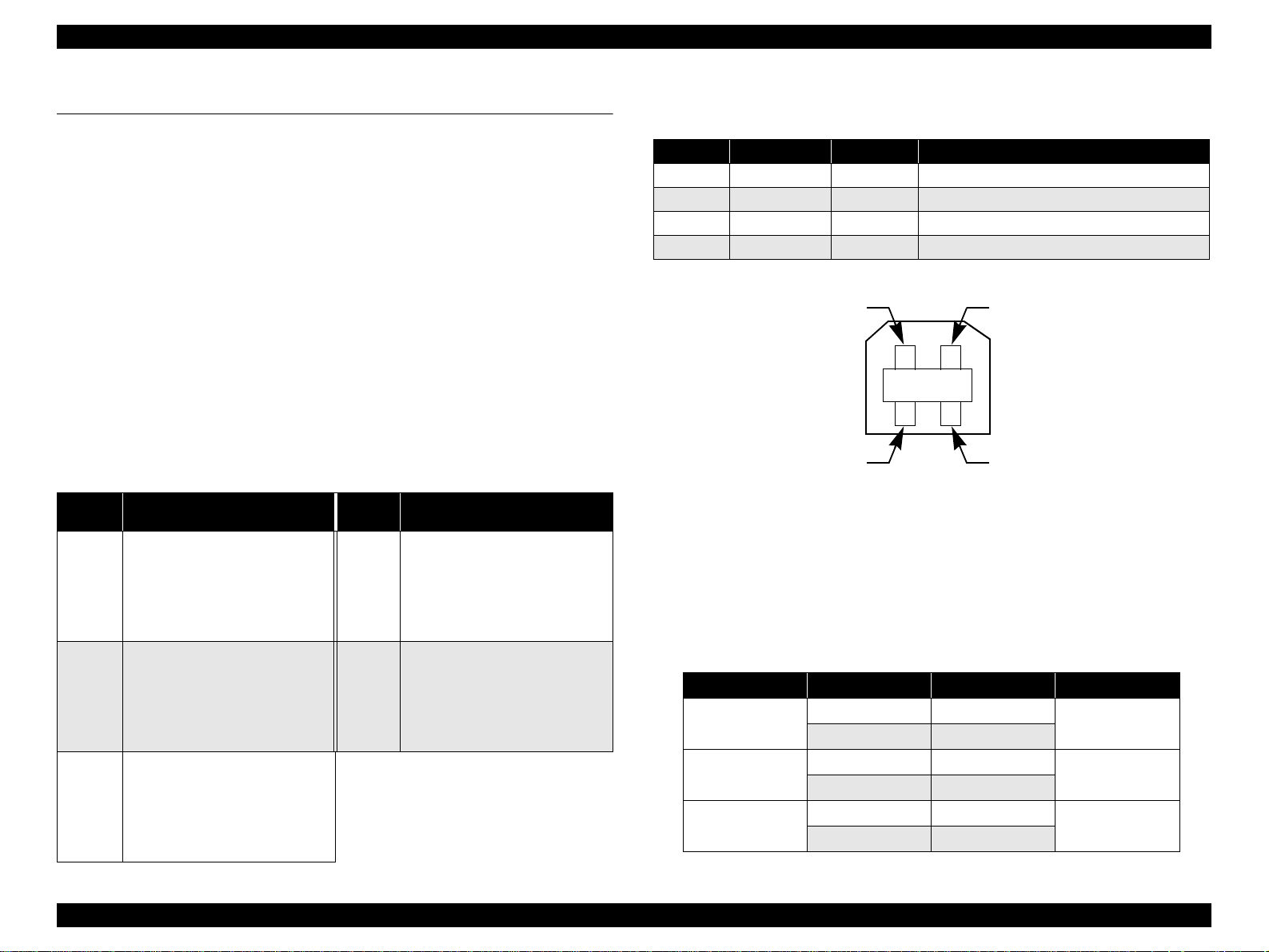
V Connector signal layout
Table 1-20. Connector pin assignment and signals
Pin No. Si gn al na me I/O Function desc ription
1 VCC - Cable power. Max. power c onsumption is 2mA.
2 -Data Bi-D Data
3 +Data Bi-D Data, pull up to +3.3V via 1.5K ohm resistor.
4 Ground - Cable ground
Pin #2
Pin #3
Pin #1
Pin #4
Figure 1-9. USB pin Assignment
V Product ID
T 0x080D (Stylus CX4500/CX4600)
T 0x080E (Stylus CX3500/CX3600/CX3650)
V Endpoint attribute
Table 1-21. Endpoint attrib ute
I/F No. Endpoint Addr e ss Endpoint Type Linked Interface
0x00
0x01
0x02
0x01 Bulk In
0x02 Bulk Out
0x03 Bulk In
0x04 Bulk Out
0x05 Bulk In
0x06 Bulk Out
Scanner
Printer
Card
PRODUCT DESCRIPTION Interface 2 2
Page 23
EPSON Stylus CX3500/CX3600/CX3650/CX4500/CX4600 Revision A
1.3.2 Standard Card Slots (only for Stylus CX4500/CX4600)
1.3.2.1 Memory card
Table 1-22. Memory card
Memory card standa rd s Slots Supported memory c ar ds
Compact
Flash
SmartMedia
Memory
Stick
Memory
Stick PRO
SD
MultiMedia
Card
xD-Picture
Card
CF+ and CompactFlash
Specification Revision 1.4
compliant
SmartMedia Standard 2000
compliant
MemoryStick Standard version
1.3 compliant
MemoryStick Standard Memory
Stick PRO Format Spec ifications
version 1.0 compliant
SD Memory Card Specifications
/ PART1. Physical Layer
Specification Version 1.0
compliant
MultiMediaCard Standard
compliant
TM
xD-Picture Card
Specification Version 1.00
compliant
Card
CF Type II slot
SmartMedia slot
Memory Stick/
Memory Stick
PRO slot
SD/MMC slot
xD-Picture Card
slot
• Compact Flash
(memory car d onl y )
•Microdrive
Smart Media
(maximum capaci ty: 128 MB)
• Memory Stick
(maximum capacity: 128 MB,
including versions with memory
select function)
• MagicGate Memory Stick
(maximum capacity: 128 MB,
copy protection func tio n is not
supported)
• Memory Stick Duo
(requires Memory Stick Duo
adapter)
• Memory Stick Duo
(requires Memory Stick Duo
adapter)
• Memory Stick PRO Duo
• (requires Memory Stick Duo
adapter)
• SD (Secure Digital) memory
card
• miniSD card
(requires SD adapter)
MultiMediaCard
xD-Picture Card
CAUTION
Note the following caution points when handling the memory card.
T Since the SD card and Memory Stick share the same slot, only
one can be inserted at a time.
T Since the SmartMedia and xD-Picture Card share the same slot,
only one can be inserted at a time.
T When a memory card is being accessed, be sure to keep the
memory card slot's cover closed and do not touch the memory
card.
1.3.2.2 Supported power supply voltage
V 3.3V/5V (both)
V 3.3V (only)
NOTE 1: 3.3V power is supplied to media that support both 3.3V and 5V.
2: Maximum current to memory card is 500mA.
3: 5V type memory cards are not supported.
PRODUCT DESCRIPTION Interface 2 3
Page 24

EPSON Stylus CX3500/CX3600/CX3650/CX4500/CX4600 Revision A
1.3.2.3 Multi-slot operations
V Overview
T There is only one type of card that can be used to simultaneously access both
a connected computer and the direct printing function.
T The slots have assigned priority to determine which slot will be accessed first
when cards are inserted in several slots at once.
T To select a card that has been inserted in a non-active slot, the card in the
active slot must first be removed.
• Direct printing:
Only the image files in the active slot are valid and have assigned frame
numbers. The number of images will not change if a card is also inserted in
a non-selected slot.
• Connection to computer (Windows):
Only one drive is displayed at a time as a “removable disk” and only the
card that is in the active slot can be accessed via the removable disk. A card
that has been inserted into a non-selected slot cannot be accessed.
• Connection to computer (Macintosh):
Only the card in the active slot can be mounted on the desktop. A card that
has been inserted into a non-selected slot canno t be mo unted on the des ktop.
V Details
T Access priority
The access priority among slots is assigned as:
1: CF (Micro Drive)
2: Smart Media
3: Memory Stick (Memory Stick PRO)
4: SD (MMC)
5: xD-Picture Card
T Slot selection when power is turned on
If cards are inserted in several slots when the power is turned on, the active
slot is determined by the priority ranks listed above.
Example: If Smart Media and Memory Stick are both inserted at power-on,
the Smart Media slot becomes the active slot.
T Slot selection after power is turned on
When a card is removed from the active slot, the slot with the next-highest
priority becomes the active slot (if a card has been inserted in to it). There is no
need to re-insert any card befor e accessing it. If no slots contain any car ds, the
highest-priority slot (CF Micro Drive) again becomes the active slot.
Cards can be removed from non-selected slots in any order.
Example: If a memory stick and CF card are inserted while Smart Media is
selected, CF becomes selected (active) once Smart Media is
removed.
PRODUCT DESCRIPTION Interface 2 4
Page 25
EPSON Stylus CX3500/CX3600/CX3650/CX4500/CX4600 Revision A
1.4 Stand-alone Copy
1.4.1 Basic Specifications
1.4.1.1 Supported paper sizes, types and qualities
Table 1-23. Supported paper sizes, types and qualities
Paper type
Paper name
Plain Paper
Recycled Paper
DURABright Photo Paper
(DURABright I nk Glo ssy Ph oto Pa per )
Note : The quality of draft copy is not affected by “Paper type” selection.
Note *1: C onnected with Paper t ype.
*2: Paper si zes in parentheses app ly only to Stylus CX4600.
Panel
Indication
Plain Paper
Photo Paper
Quality
1
*
Plain
Paper
Photo
Paper
Paper size *
Paper size
A4
(Letter)
A4 (Letter),
10cm x 15cm
(4" x 6")
1.4.1.2 Zoom function
The zoom function provides enlarged or reduced copies of originals. The either of the
following can be selected from the operation panel.
V Actual (The state which “Fit to page” is not selected. It is the power-on default.)
The zoom factor is set to 100%.
V Fit to page
This function detects the image size of the original and automatically sets the
zoom factor of the copy according to the copy paper's printable area.
1.4.1.3 Number of copies setting
This function sets the number of copies. The setting range is 1 to 9 and 100.
1.4.1.4 Maximum copy size
V 216 x 297mm
2
Panel
Indication
A4
(Letter)
A4 (Letter),
10cm x 15cm
(4" x 6")
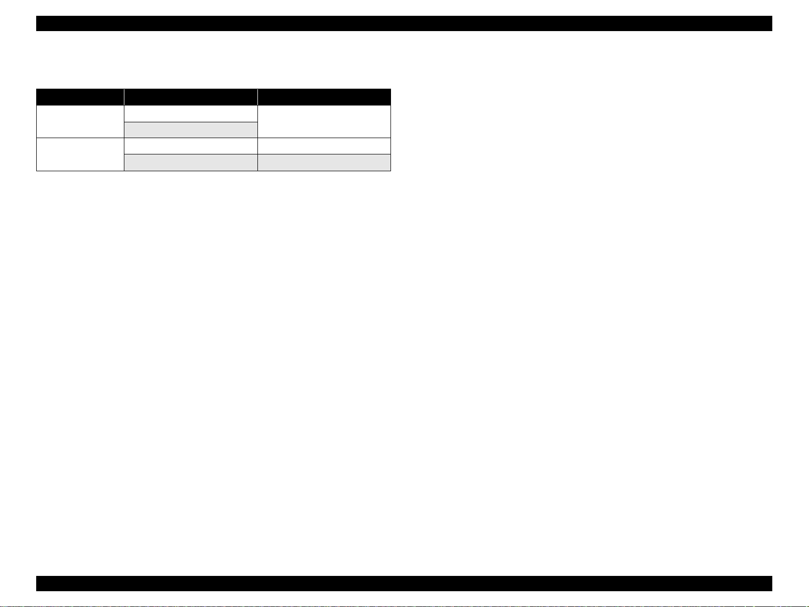
1.4.1.5 Copy layout
The following copy layout is provided according to “Paper type”, “Paper size” and
zoom selections.
V Standard copy
Provided for ordinary use with 3mm copy margin from every side.
V BorderFree copy
Border-free printing of copies occurs when the print area is set as larger than the
copy paper's size. In such cases, the outer edges of the original image may be
omitted in the printed copy.
V Small Margins copy
This function sets a 1. 5mm margin on all four sides when pr inting in order to mak e
maximum use of the original image and copy paper.
NOTE: Only “Standard Copy” can be used in draft copy mode.
Table 1-24. Copy layout
Zoom Paper type Paper size *
Plain Paper
Actual *
Fit to page *
Note *1 : Actual is the state that “Fit to page” is not selected.
1
Photo Paper
Plain Paper
2
Photo Paper
*2 : “Fit to page” automatically sets the enlarge/reduce scale so that the entire image fits
into the printable area or the border free area when border free layout is selected.
When the original image is smaller than general card size (approx. 54mm x 86mm),
the print margins will be different from the one that is defined by each layout.
The image placement uses the upper left corner as the origin and any margins that
occur during the fitting process occur along the bottom and/or right edge.
*3: Pape r sizes in parentheses apply only to Stylus CX4600.
A4 (Letter) B&W, Color Standard
10cm x 15cm (4" x 6") B&W, Color Standard
A4 (Letter),
10cm x 15cm (4" x 6")
A4 (Letter) B&W, Color Standard
10cm x 15cm (4" x 6") B&W, Color Standard
A4 (Letter),
10cm x 15cm (4" x 6")
3
B&W / Color Layout
B&W, Color Small margin
B&W, Color Border free
PRODUCT DESCRIPTION Stand-alone Copy 25
Page 26
EPSON Stylus CX3500/CX3600/CX3650/CX4500/CX4600 Revision A
1.4.1.6 Multiple copies from an original
Second and subsequent copies can be printed from an original without scanning.
When printing two or more copies, under the following settings the scan data can be
stored in the unit's memory so that the second and subsequent copies can be printed
without scanning.
V “Draft” mode (monochrome/color)
V “Text” mode (monochrome)
1.4.2 Copy Speed
1.4.2.1 Black Copy Speed
V Plain Paper – Draft 12.6 cpm (Copy per minute), Plain Paper – 3.1 cpm
V Black e-Memo text A4 size pattern, zoom 100%
The above speed is for the second and subsequent copies (the time between
ejection of the first page to ejection of the second page).
1.4.2.2 Color Copy Speed
V Plain Paper – Draft 11.6 cpm (Copy per minute)
V Color e-Memo text A4 size pattern, zoom 100%
The above speed is for the second and subsequent copies (the time between
ejection of the first page to ejection of the second page)
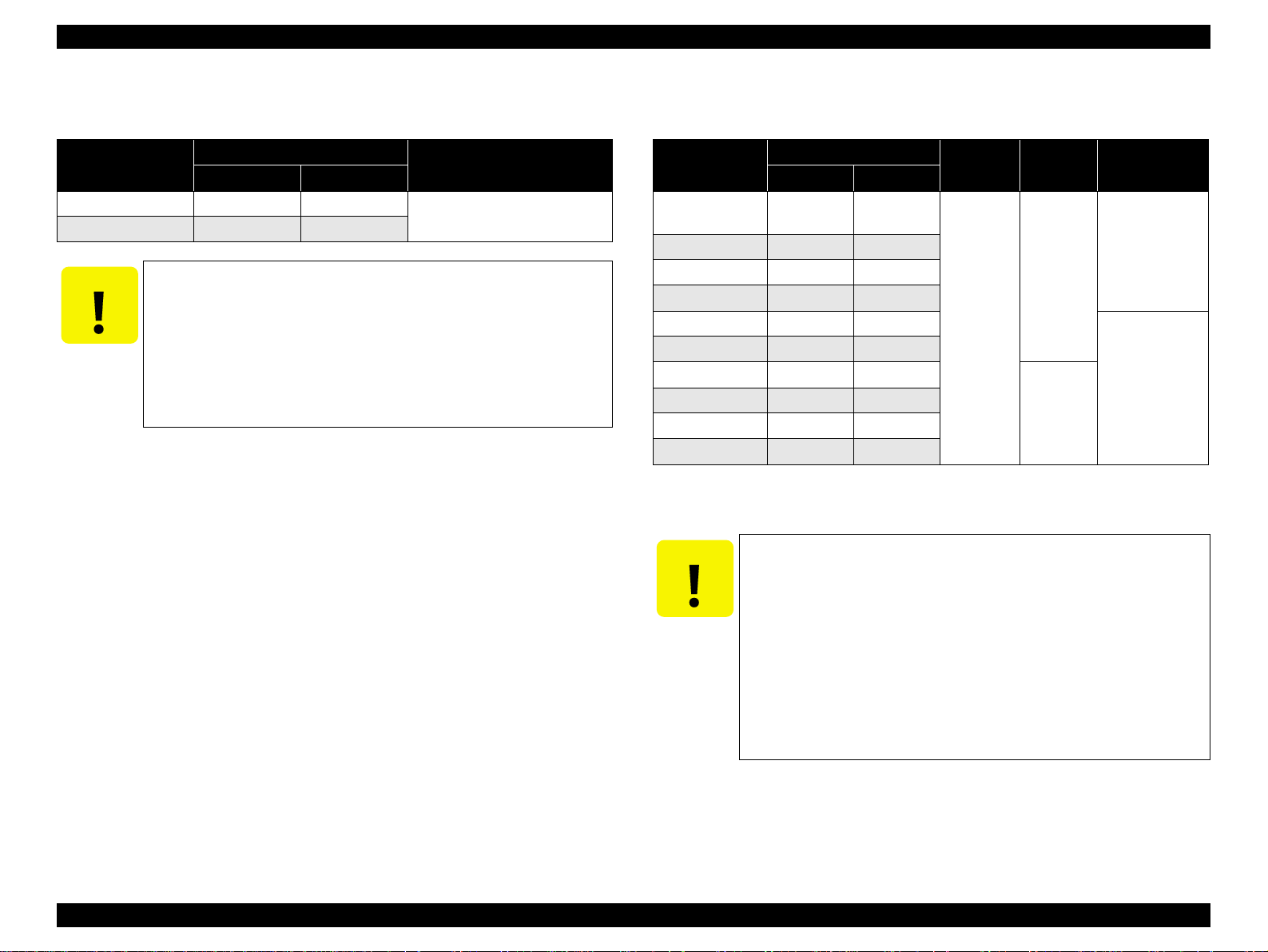
1.4.3 Configuration for copying
Table 1-25. Configuration for copying
Copy Mode setting Scan and Print configuration
Paper type
Plain Paper
Photo Paper
(A4/Letter)
Photo Paper
(smaller than
A4/Letter)
Draft (Plain
paper only)
B&W /
Color
B&W
Color
B&W
Color
B&W
Color
B&W
Color
Enlarge /
Reduce*
(%)
100
(Default)
100
(Default)
100
(Default)
100
(Default)
100
(Default)
100
(Default)
100
(Default)
100
(Default)
Note *1 : “Default” is the state in which “Fit to page” is not selected. When “Fit to page” is
selected, scan resolution will be optimized according to enla rge/ reduce scale.
*2: With “Photo Paper”, composite black will be used in both B&W and color mode.
*3: With “Draft”, both real black and composite black will be used for black printing.
“PEC” technology will be used.
*4 : “PEC” technology will be used for A4 or Letter size printing.
Scan
1
resolution*
(M x S dpi)
600 x 300 360 x 360 VSD1 Off On C1
300 x 600 360 x 720 VSD1 On On C1
600 x 600 720 x 1440*
600 x 600 720 x 1440*4VSD3 On On C2
600 x 600 720 x 1440 VSD3 On On C3
600 x 600 720 x 1440 VSD3 On On C3
300 x 100 360 x 120 VSD1 Off On C4
300 x 100 360 x 120 VSD1 Off On C4
1
(H x V dpi)
Print
resolution
Dot size MW
4
VSD3 On On C2
High
Speed
LUT
PRODUCT DESCRIPTION Stand-alone Copy 26
Page 27
EPSON Stylus CX3500/CX3600/CX3650/CX4500/CX4600 Revision A
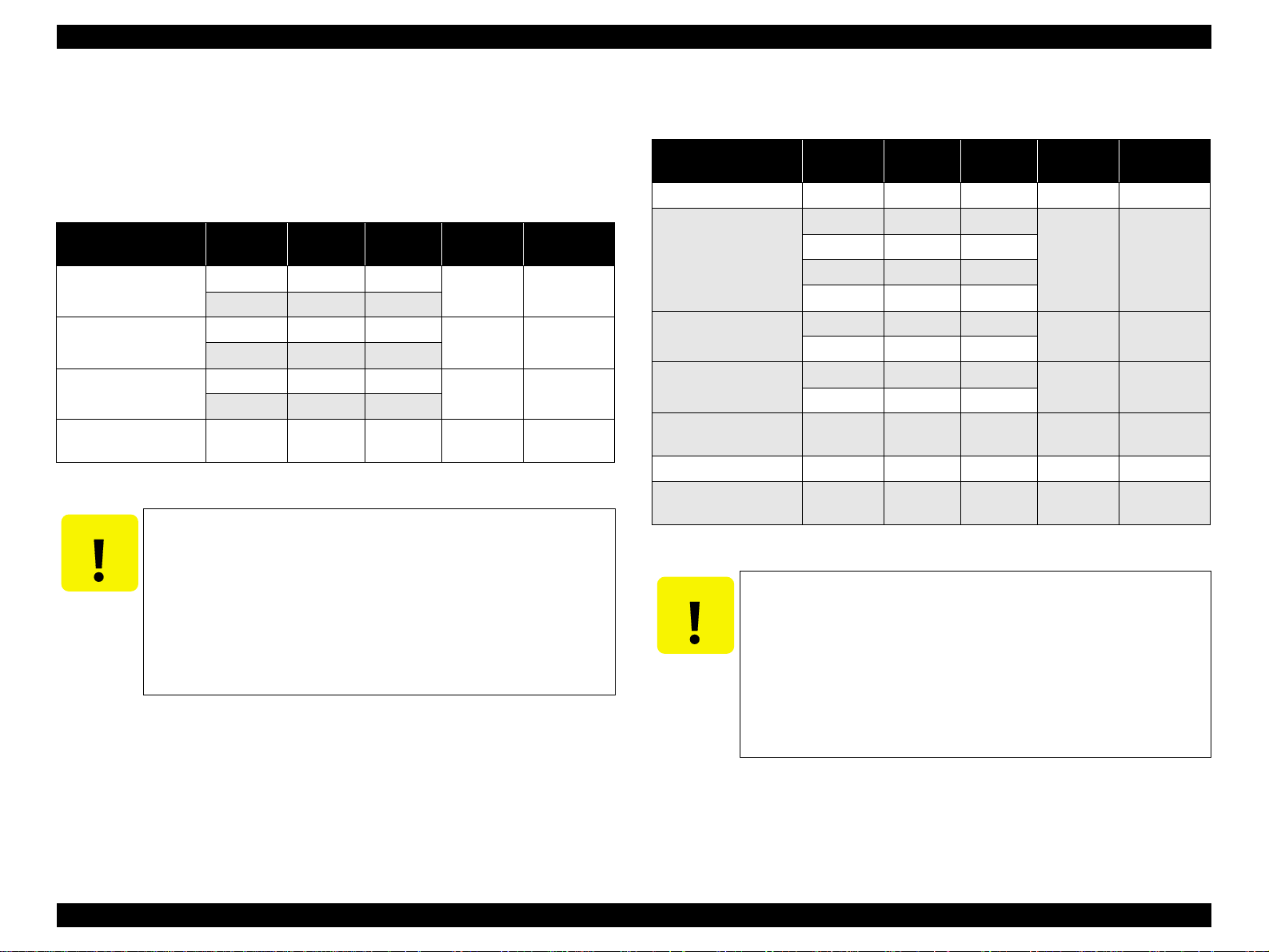
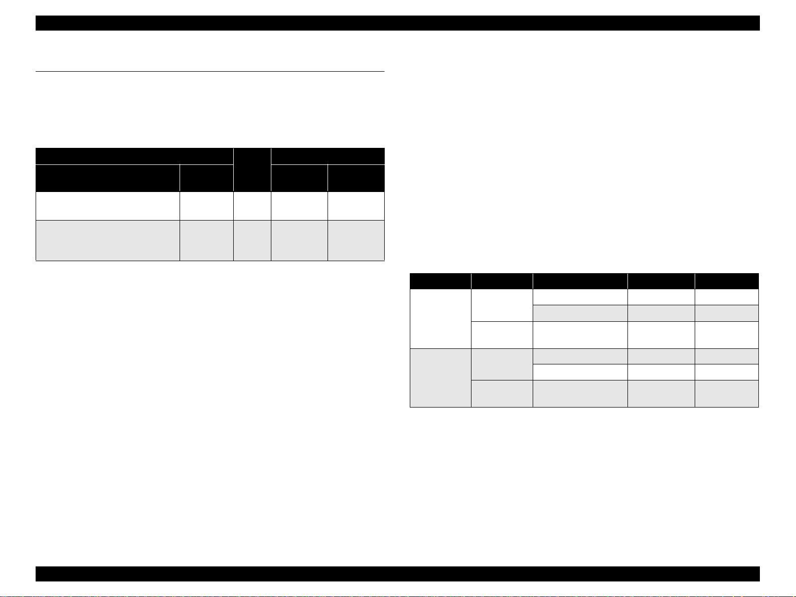
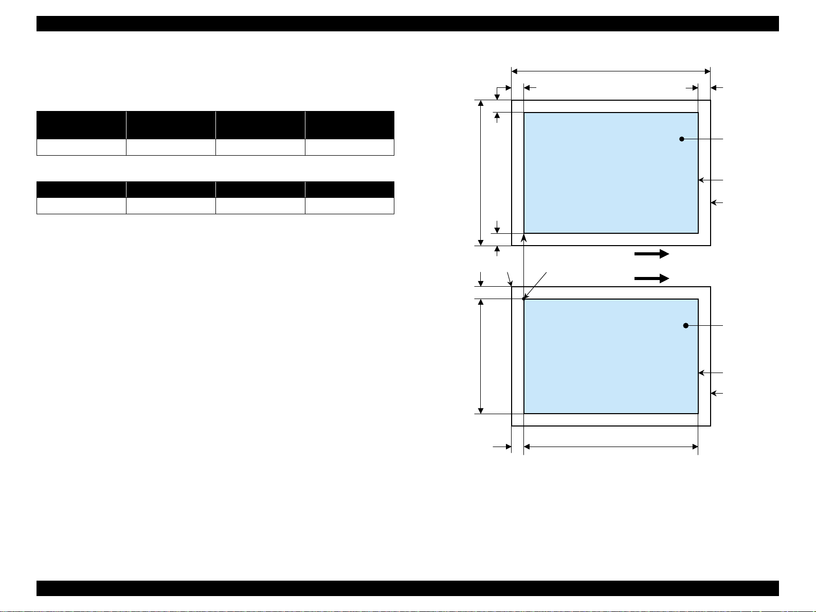
1.4.4 Relation between original and copy
1.4.4.1 Standard copy
The following table shows the relative positioning of the original and copy.
Table 1-26. Original (scanner)
RW
(readable width)
216 mm (8.5") 1.5 mm ± 1 mm 297 mm (11.7") 1.5 mm ± 1 mm
RM LM TM BM
3 mm (0.12") 3 mm (0.12") 3 mm (0.12") 3 mm (0.12")
Note : Refer to “1.2.1.4 Paper Support” (p.12) for paper width (PW) and paper length (PL).
(out-of-range left margin)
OLM
Table 1-27. Copy (printer)
RL
(readable length)
OTM
(out-of-range top margin)
OLM
RM
TopPW
LM
TopRW
*2*1
PL
Right side of copy
Print direction
Scan direction
BMTM
a
a
Copy
Print area
Copy paper
Original
(face down)
Scan area
Scan bed
Right side of original
OTM RL
Note *1: This indicates the top left corner of the original. Normally, this corner is aligned
with the scan bed's top right corner as the reference point.
*2 : This indicates the scan start position at the top left of the original, which
corresponds to the print start position at the top left of the copy. The bottom right
corner position of the copy is within the print area but varies accordi ng to the
enlarge/reduce setting.
Figure 1-10. Standard copy
PRODUCT DESCRIPTION Stand-alone Copy 27
Page 28
EPSON Stylus CX3500/CX3600/CX3650/CX4500/CX4600 Revision A
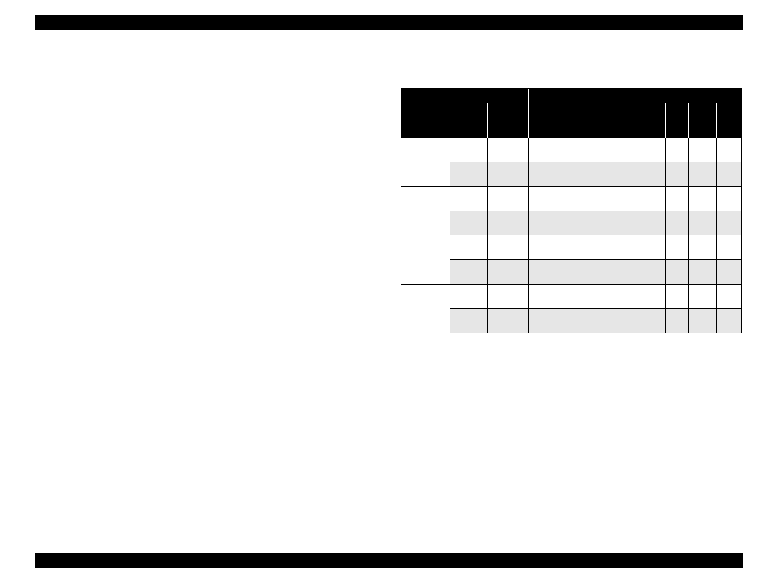
1.4.4.2 BorderFree Copy
The following table shows the relative positioning of the original and copy.
Table 1-28. Original (scanner)
RW
(readable width)
216 mm (8.5") 1.5 mm ± 1 mm 297 mm (11.7") 1.5 mm ± 1 mm
RO LO TO BO
2.5 mm (0.09") 2.5 mm (0.09") 3 mm (0.12") 5 mm (0.2")
Note : Refer to “1.2.1.4 Paper Support” (p.12) for paper width (PW) and paper length (PL).
(out-of-range left margin)
OLM
Table 1-29. Copy (printer)
RL
(readable length)
OTM
(out-of-range top margin)
LO
OLM
TO
PL
Right side of copy
TopPW
a
Print direct ion
*2*1
Scan direction
a
TopRW
BO
Copy
Print area
Copy paper
Original
(face down)
Scan area
Scan bed
Right side of original
OTM RL
Note *1: This indicates the top left corner of the original. Normally, this corner is aligned
with the scan bed's top right corner as the reference point.
*2 : This indicates the scan start position at the top left of the original, which
corresponds to the print start position at the top left of the copy. The bottom right
corner of the print area varies according to th e scale setting in the print area.
Figure 1-11. BorderFree Copy
PRODUCT DESCRIPTION Stand-alone Copy 28
Page 29
EPSON Stylus CX3500/CX3600/CX3650/CX4500/CX4600 Revision A
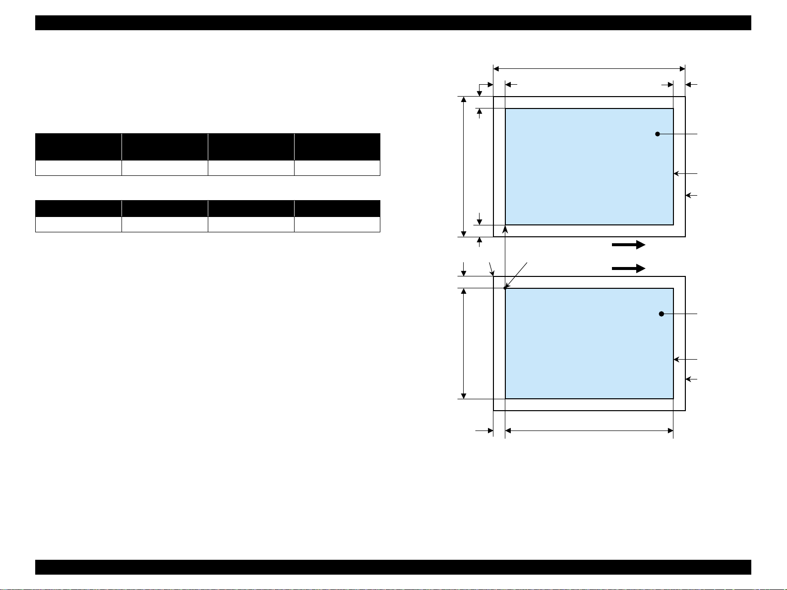
1.4.4.3 Small Margins copy
The following table shows the relative positioning of the original and copy.
Table 1-30. Original (scanner)
RW
(readable width)
216 mm (8.5") 1.5 mm ± 1 mm 297 mm (11.7") 1.5 mm ± 1 mm
RM LM TM BM
1.5 mm (0.06") 1.5 mm (0.06") 1.5 mm (0.06") 1.5 mm (0.06")
Note : Refer to “1.2.1.4 Paper Support” (p.12) for paper width (PW) and paper length (PL).
(out-of-range left margin)
OLM
Table 1-31. Copy (printer)
RL
(readable length)
OTM
(out-of-range top margin)
OLM
RM
TopPW
LM
TopRW
*2*1
PL
Right side of copy
Print direction
Scan direction
BMTM
a
a
Copy
Print area
Copy paper
Original
(face down)
Scan area
Scan bed
Right side of original
OTM RL
Note *1: This indicates the top left corner of the original. Normally, this corner is aligned
with the scan bed's top right corner as the reference point.
*2 : This indicates the scan start position at the top left of the original, which
corresponds to the print start position at the top left of the copy. The bottom right
corner position of the copy is within the print area but varies accordi ng to the
enlarge/reduce setting.
Figure 1-12. Small Margins copy
PRODUCT DESCRIPTION Stand-alone Copy 29
Page 30

EPSON Stylus CX3500/CX3600/CX3650/CX4500/CX4600 Revision A
1.5 Memory Card Print (only for Stylus CX4500/CX4600)
1.5.1 Basic Specifications
1.5.1.1 File system
DCF Version 1.0 is the only file system that can be used with this unit's stand-alone
printing functions. Operation is not guaranteed when any other file system is used.
The file system used by the card reader function depends on the host's specifications.
For a detailed description of the DCF specifications, see the “Design Rule for Camera
File System Standard, DCF Version 1.0, JEIDA-49-2-1998”.
1.5.1.2 Media format
V Media must be formatted according to the DCF Version 1.0 standard.
V DOS FAT formats (FAT12, FAT16) and single partition (basic partition)
1.5.1.3 File formats
The file formats supported by this unit are described below.
V JPEG files (*.JPG)
These are photo data files that comply with the Exif Version 2.1 or Version 2.2
standard.
V Camera specification files (*.MRK)
These are definition files used when in camera specification mode. An
“AUTOPRINT.MRK” file whose full path name is no longer than 32 ch aracters is
valid.
Note, however, any file that is saved in the following directories or their sub-directories
cannot be included as files to be printed.
V Directories containing system properties or hidden properties
V Directories that contain any double-byte characters in the directory name
V “RECYCLED ” : Windows directory for deleted file s
V “PREVIEW” : Directories containing CASIO's DSC thumbnail images
V “SCENE” : Directories containing data for CASIO's DSC Best Shot
function
V “MSSONY” : Directories containing SONY's DSC e-mail image data, voice
memos, video files, or non-compressed images
1.5.1.4 Valid image size
The maximum image size handled by this unit is:
V Horizontal : 120 ≤ X ≤ 4600 (pixels)
V Vertical : 120 ≤ Y ≤ 4600 (pixels)
1.5.1.5 Maximum number of photo data files
This unit can handle up to 999 photo data files. If the amount of photo data to be
recorded exceeds the capacity of one memory card, this unit uses file sorting rules to
sort the photo data into v ali d photo data in f rames number ed f rom 1 to 999. Al though it
is possible to print photo data files with frame numbers over 999 that have been
specified for printing by camera specification files, the maximum number of frames
that can be specified is 999 frames.
If you insert a memory card t hat cont ains over 999 ph oto d ata fi les, only fi les up to 999
will be printed by the “Print All” or “Print index sheet” functions.
1.5.1.6 Thumbnail image data
This unit handles thumbnail image data in the DCF Version 1.0 format (Exif format,
160 x 120 pixels).
During this unit's Index sheet and memory card printing modes, the layout is 80
thumbnails per sheet (when using plain paper or special paper in high-speed print
mode).
1.5.1.7 File sorting
This unit stores all photo data files in the memory, using the photo data files' full-path
file names (for example, “\DCIM\100EPSON\EPSN0000.JPG”), and assigned photo
frame numbers. Since photo frame numbers are assigned based on this unit's own
proprietary file sorting rules, the assigned frame numbers do not necessarily match
those indicated by digital cameras.
PRODUCT DESCRIPTION Memory Card Print (only for Stylus CX4500/CX4600) 30
Page 31

EPSON Stylus CX3500/CX3600/CX3650/CX4500/CX4600 Revision A
1.5.1.8 File sorting rules
This unit sorts photo data files based on the following prioritization rule.
T File name is sorted in ASCII order as full path name.
NOTE: Sorting results are not guaranteed if two files have matching full-path file
names. (Matching full-path file names are not allowed under the DOS
specification.)
1.5.1.9 Rules for acquisition of date/time data
The following priorities are used to fetch date and time information from photo data
files.
1. Date/time data that complies with the standard format (Exif) for digital
cameras
2. Date/time data that complies with the DOS standard file system (file time
stamps)
3. Fixed values (01/01/1970, 00:00:00)
Note that the date/time data assigned to individual photo data files does not necessarily
match the date/time when the photo was actually taken. The photo date/time may be
modified due to the digital camera's calendar settings (presence/absence of functions,
incorrect date/time settings, etc.), processing of the photo data after the photo was
taken, or subsequent saving of data. In such cases, this unit performs the relevant
processing based on the most recently modified date/time data.
1.5.2 Functions
1.5.2.1 List of functions
The memory card print menu and its settings are listed in the following table. The
values shown in this table indicate the total number of options and the number of pages
or copies that can be printed consecutively.
Table 1-32. List of functions
Memory card
printing
Print index sheet Print Index Sheet None Plain Paper 1 1
Print from index
sheet
Print all images Print All / DPOF
DPOF * Print All / DPOF
Note "*": It is available only DPOF file exists in the memory card.
Note : “Print index sheet” will be selected as default func tion of Memory Card Prin t. But when
DPOF file exists in the memory card, “Print All / DPOF” will be selected as default and
DPOF print can be done easily.
Mode selection Layout Paper type
Print From Index
Sheet
•Standard
• Border free
•Standard
• Border free
•Standard
• Border free
• Plain Paper
• Photo Paper
• Plain Paper
• Photo Paper
• Plain Paper
• Photo Paper
Paper
Page/copies
size
1 to 3
2
(according
to marking)
21
2 1 to 99
1.5.1.10 Number of sheets which can be printed in total
Printing sum total number of sheets presupposes that it is possib le to 999 sheets.
Moreover, the printing sum total number of sheets per sheet is possible to 99 sheets.
PRODUCT DESCRIPTION Memory Card Print (only for Stylus CX4500/CX4600) 31
Page 32

EPSON Stylus CX3500/CX3600/CX3650/CX4500/CX4600 Revision A
1.5.2.2 Memory card printing mode
V Print index sheet printing
This function prints thumbnail images (stored in the memory card) onto an Index
Sheet (form) that is marked for selecting images.
The combinations of paper types and paper sizes are fixed as follows.
V Print from index sheet printing
This function prints selected images onto the sheet output by index sheet printing.
V Print all images
This function prints all of the image files stored in the memory card. As shown
below, the number of printed pages dep ends on the nu mber of copies to be pri nted.
The settings are described below.
V DPOF printing
In this mode, the photo frame numbers previously specified via the camera are
printed in the number of pages specified via the camera. Only the paper type and
layout are specified on the printer side. If the layout assigned multiple photos per
output sheet, photos that have different frame sizes are automatically assigned in
the specified number of pages in numerical order (of the specified photo frame
numbers). If index print mode was set via the camera, this unit will print in DPOF
index layout. (When in DPO F print mode, th e mode cannot be swit ched by writ ing
the print file specification from the host after inserting the memory card.)
Table 1-33. Memory card printing mode
Setting Memory card printi ng mode Description Option, setting range, etc.
Layout
(no menu)
Paper
type
Paper size
Pages/
copies
Quality
• Print from index sheet printing
• Print all images
• DPOF printing
Print index sheet printing Fixed Plain Paper
• Print from index sheet printing
• Print all images
• DPOF printing
Print index sheet printing Fixed A4 or Letter *
• Print from index sheet printing
• Print all images
• DPOF printing
Print index sheet printing Fixed
Print from index sheet printing
Print all images
DPOF printing
Print index sheet printing Fixed
• Print from index sheet printing
• Print all images
• DPOF printing
Sets print
layout
Sets paper
type
Sets paper
size
Sets number
of printout
Sets number
of printout
Sets number
of printout
Sets print
quality
Fixed in combinatio n with paper
type and paper size (refer to
“1.5.4 Layout and Paper Type,
Paper Size” (p.36))
Plain Paper or Photo Paper
1
A4 or 10cm x 15cm *
Letter or 4" x 6" *
Fixed as 1 page (can va r y
according to the number of
image files)
1 to 3 (set by the marking to the
index sheet)
1
The number of copies specified
via the camera is used. The
setting range is 1 to 99 copies
(default i s 1 co py).
Prints it by the quality of 360 x
720dpi of Plain Paper. Only the
Color print is supported.
Fixed according to pa per type
(refer to “1.5.9 Relation
between Paper Ty pe and
Quality” (p.40))
2
3
Note *1: A4 size will be used for Stylus CX3500/CX3600/CX3650/CX4500.
Letter size will be used for Stylus CX4600.
*2: A4 or 10cm x 15cm size will be used for Sty lu s CX35 00 /CX36 00 /CX3 65 0/ CX45 00 .
*3: Lett er or 4" x 6" size will be used for Stylus CX4600.
PRODUCT DESCRIPTION Memory Card Print (only for Stylus CX4500/CX4600) 32
Page 33

EPSON Stylus CX3500/CX3600/CX3650/CX4500/CX4600 Revision A
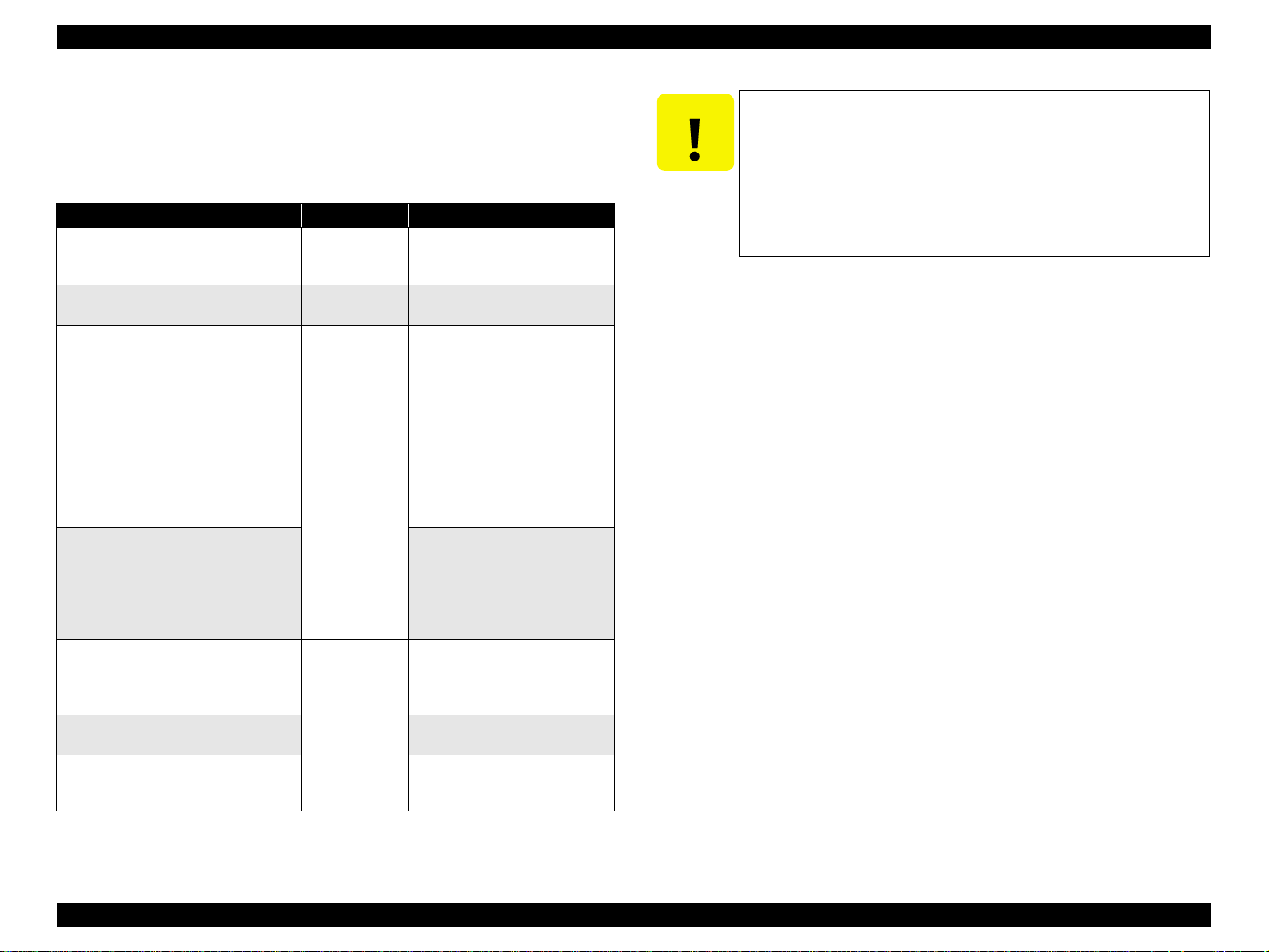
1.5.3 Index Sheet
V 30 thumbnail images are assigned per index sheet.
V There are 3 marking areas for each thumbnail and you can set the number of
copies up to 3.
V “Paper type” and “Paper size” can be set from the operation panel.
V The layout is fixed according to the paper type and it is not indicated on the sheet.
(Refer to “1.5.4 Layout and Paper Type, Paper Size” (p.36))
V Images are arranged in the Index sheet in ascending order (of image file number).
(Refer to “1.5.1.7 File sorting” (p.30) and “ 1 .5.1.8 File sorting rules” (p.31))
V Index sheet will be printed from the last page, in descending order. (The sheet
containing first thumbnail comes top of printouts.)
V The mode transition may occur from “Print index sheet” to “Print from index
sheet” when the “Print index sheet” completes successfully.
Figure 1-13. Sample of index sheet
PRODUCT DESCRIPTION Memory Card Print (only for Stylus CX4500/CX4600) 33
Page 34

EPSON Stylus CX3500/CX3600/CX3650/CX4500/CX4600 Revision A
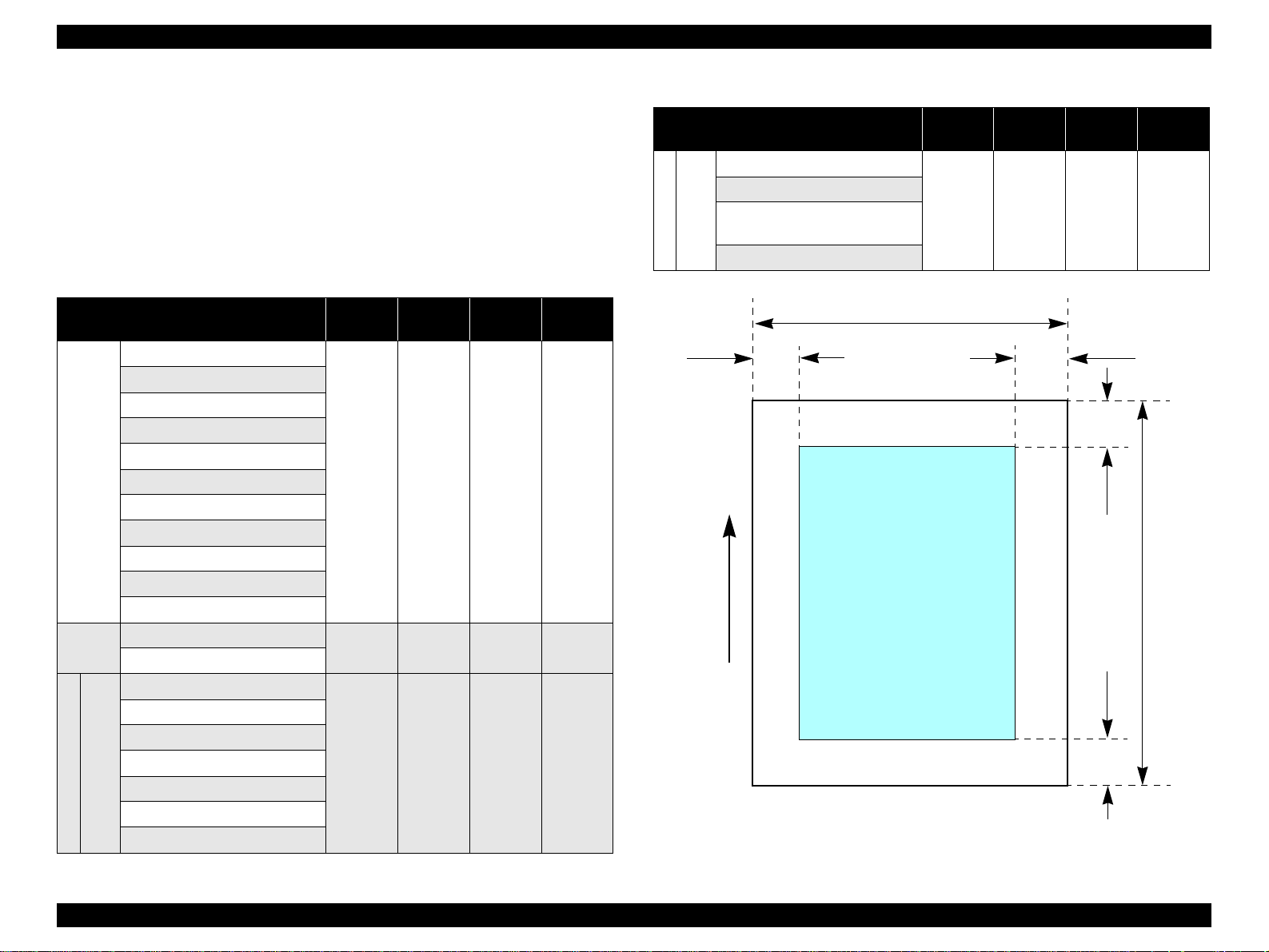
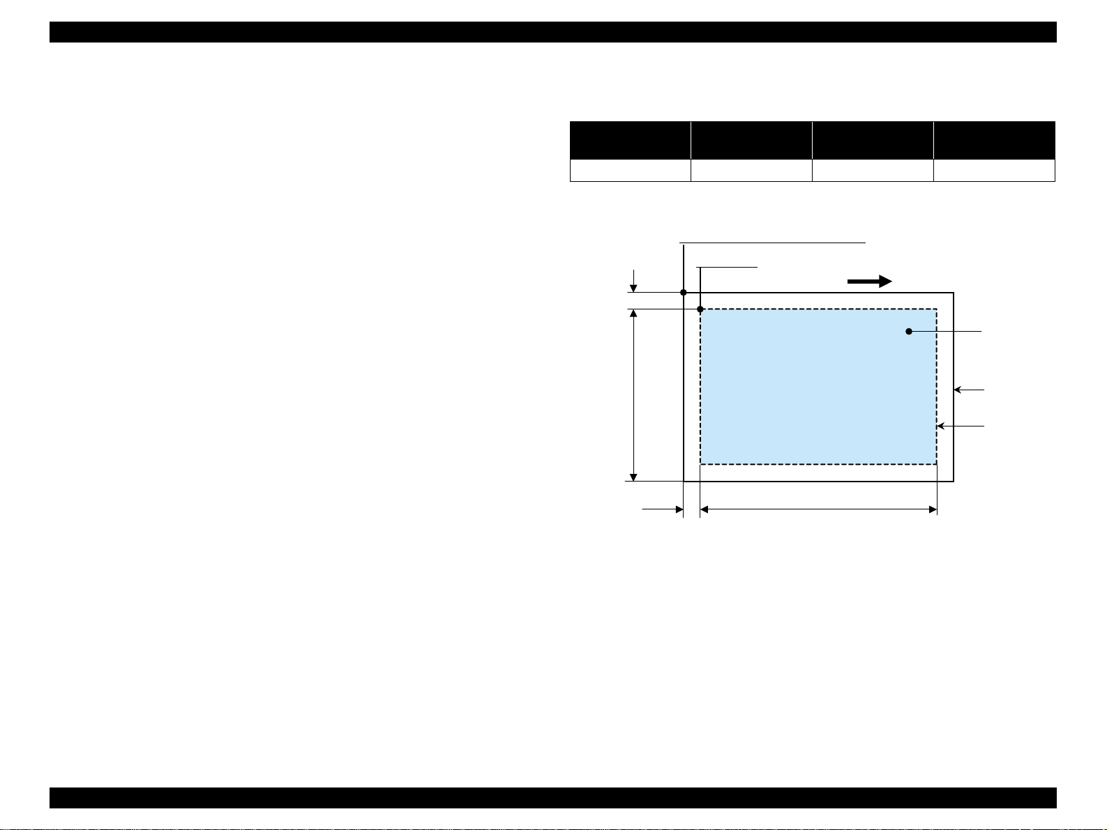
1.5.3.1 Rules for scanning index sheets
V Index sheet scan range
T Set index sheet in scanner
• Place the side to be scanned face down relative to the scan bed, as described
below.
Align the corner of the sheet to the upper left origin point and make sure the
sheet is straight. Angled setting of the sheet is allowed as long as the sheet
remains within the scan bed's scan range (the maximum angle on the scan
bed is about 2.8°).
• The cover must be closed on the original to enable scanning. (This is to
prevent any shifting of the position marks while s canning).
• Do not use paper that allows images to “bleed through” to the rear side.
(This is to prevent empty bubbles from being filled in by “bleed-through”.)
T Set scan area and original
Table 1-34. Set scan area and o riginal
RW
(readable width)
216 mm (8.5") 1.5 mm ± 1 mm 297 mm (11.7") 1.5 mm ± 1 mm
Place the Index Sheet face down with its top edge aligned to the left edge of
the scan bed, and with the corner of the paper set to the original's top left
position.
(out-of-range left margin)
OLM
RL
(readable length)
(out-of-range top margin)
OLM
RW
OTM
Original's top left alignment position
First pixel
OTM
Figure 1-14. Set scan area and original
Scan direction
RL
Operator's side
a
Set original face down,
with top aligned in the
direction of the origin.
Scan bed
Scan area
PRODUCT DESCRIPTION Memory Card Print (only for Stylus CX4500/CX4600) 34
Page 35

EPSON Stylus CX3500/CX3600/CX3650/CX4500/CX4600 Revision A
V Basic specifications for scanning of index sheets
T Scanning rules for index sheet
Check if following symbols are found or not.
Table 1-35. Symbols check
No. Symbols Usage
Left top triangle (1) Left reference position
1
Right top “O” of EPSO N ( 1) Right reference position
2
Right top block codes (36) Sheet information (memory card ID, page)
3
Optional mark of “ALL” (1)
4
Image marks (3x30)
5
Determines whether or not to print all images in the
sheet
Determines whether or not to print each image up to 3
copies. Left most is 1, center is 2 and right most is 3.
• When two or three marks of one image are filled, larger number will be used
for the number of copies. (ex. 1 and 3 are filled, number of copies is 3.)
• When the optional “ALL” mark is filled, all images in the sheet will be
printed one by one regardless of each image mark is filled or not.
• Index sheet error will be caused when any of image mark or “ALL” mark is
not filled.
• Index sheet error will be caused when “Left top triangle”, “Right top
EPSON” and “Block codes” are not found correctly due to something like
smear.
• Place the index sheet so that the “Left top triangle” can meet the left top
corner of the scanner.
1
3
4
5
Figure 1-15. Symbols check
OK patterns
1 2 3 1 2 3
2
<OK/NG mark samples>
• More than half part of the mark should be filled.
• Outside of each mark should not be filled excessively.
T Errors during scanning or printing of index sheets
NG patterns
• Stops scanning and returns to the menu screen if the card is removed while
an index sheet is being scanned or printed.
• Index sheet error (No index sheet) is displayed if the sheet cannot be
scanned because it is dirty, set backwards, etc.
• Index sheet error (Incorrect marking) is displayed if the image bubbles
1 2 3 1 2 3
Figure 1-16. OK/NG mark samples
cannot be read because they are not filled in correctly.
• Index sheet error (Incorrect card) is displayed if, after printing an index
sheet, you try to print from a non-matching memory card, su ch as a different
(replacement) card or a re-edited version of the same card.
PRODUCT DESCRIPTION Memory Card Print (only for Stylus CX4500/CX4600) 35
Page 36

EPSON Stylus CX3500/CX3600/CX3650/CX4500/CX4600 Revision A
1.5.4 Layout and Paper Type, Paper Size
The layout/paper type and size combinations that can be selected are listed below.
Table 1-36. Layout and Paper Type, Paper Size
Layout Paper type Paper size Description
Border free Photo Paper
1-up with borders Plain Paper
20-up —
80-up —
Note 1: A4 or 10cm x 15cm size will be used for Stylus CX3500/CX3600/CX3650/CX4500.
2: Letter or 4" x 6" size will be used for Stylus CX4600.
• A4, 10cm x15cm *
• Letter, 4" x 6" *
• A4, 10cm x15cm *
• Letter, 4" x 6" *
10cm x15cm *
4" x 6" *
A4 *
Letter *
2
1
2
1
Prints with no margins along top,
2
bottom and both si de s
1
Prints with 3 mm margins along
2
top, bottom and both sides
1
Prints 20 frames per page, laid out
in 5 columns and 4 rows (For
DPOF index print only)
Prints 80 frames per page, laid out
in 10 columns and 8 rows (F or
DPOF index print only)
1.5.5 Options
1.5.6 Trimming Function
A trimming function is provided as a means of coordinating photo data with the types
of photo frames handled by this unit. This function is always activated so that printing
photo data is in shapes that fit these photo frames.
This function is described briefly below.
The printed photo frame and the photo to be printed are matched in length along one
side and the photo is resized along the perpendicular side to fit the frame on that side.
Any part of the photo that does not fit within the photo frame is trimmed away (not
printed).
V The image below shows an example in which the photo data is aligned vertically
with the photo frame.
These parts are
trimmed.
V The image below shows an example in which the photo data is aligned
horizontally with the photo frame.
Photo frame
(print area)
The functions below will be available by marking to options on the index sheet.
V Prints all photos one by one shown on the index sheet.
These parts are trimmed.
Photo frame
(print area)
Figure 1-17. Trimming Function
PRODUCT DESCRIPTION Memory Card Print (only for Stylus CX4500/CX4600) 36
Page 37

EPSON Stylus CX3500/CX3600/CX3650/CX4500/CX4600 Revision A
1.5.7 Assignment Rules for Photo Frame Numbers and Rotation
The rules concerning photo fram e n umber s that ar e ref erred when as sig ning ph otos ar e
described below. The numbers sh own in each diagr a m and ph oto frame below indicate
the photo frame numbers used for various types of layout.
The direction of the number shown in each photo frame matches the direction of the
printed photo to which the horizontal photo data was allocated. When there are more
pixels vertically than horizontally, the vertical photo data is allocated instead, and the
number shown in the figure below is then rotated 90° before being printed. In Index
printing mode, the numbers are printed as they are shown below, regardless of the
shape of the photo data.
However, w hen the photo data has an equal number of pixels vertically and
horizontally the phot os are printed without rotation, regardless of the layout.
(Note: the vertical photo data refers to when the photo data file itself is set for a vertical
(portrait) orientation. Photo data is defined as the vertical photo data if it is taken by a
digital camera with a portrait position detecting function.)
Top edge
<Border-free> <1 sheet with borders>
12345678
9 10111213141516
17 18 19 20 21 22 23 24
25 26 27 28 29 30 31 32
33 34 35 36 37 38 39 40
41 42 43 44 45 46 47 48
49 50 51 52 53 54 55 56
57 58 59 60 61 62 63 64
<20-up>
65 66 67 68 69 70 71 72
73 74 75 76 77 78 79 80
<80-up>
Figure 1-18. Assignment Rules for Photo Frame Numbers and Rotation
PRODUCT DESCRIPTION Memory Card Print (only for Stylus CX4500/CX4600) 37
Page 38

EPSON Stylus CX3500/CX3600/CX3650/CX4500/CX4600 Revision A
1.5.8 Layout Drawings
1.5.8.1 Border free
BD
H
C
A
Paper
1.5.8.2 1-up with borders
A
C
FEG
Printable
area
DB
H
Printable area
Figure 1-20. 1-up with borders
FEG
Figure 1-19. Border free
Table 1-38. 1-up with borders (unit: mm (inch))
Paper type A B C D E F G H
Table 1-37. Border free (unit: mm (inch))
Paper type A B C D E F G H
1
A4 *
10cm x 15cm *1101.60 152.40 106.68 160.53 2.54 2.54 2.96 5.08
Letter *
4" x 6" *
210.00 297.00 215.08 305.04 2.54 2.54 2.96 5.08
215.90
2
(8.50)
101.60
2
(4.00)
279.40
(11.00)
152.40
(6.00)
220.98
(8.70)
106.68
(4.20)
287.53
(11.32)
160.53
(6.32)
2.54
(0.10)
2.54
(0.10)
2.54
(0.10)
2.54
(0.10)
2.96
(0.12)
2.96
(0.12)
5.08
(0.20)
5.08
(0.20)
10cm x 15cm *1101.60 152.40 95.60 146.40 3.00 3.00 3.00 3.00
Note 1: A4 or 10cm x 15cm size will be used for Stylus CX3500/CX3600/CX3650/CX4500.
A4 *
Letter *
4" x 6" *
1
210.00 297.00 204.00 291.00 3.00 3.00 3.00 3.00
215.90
2
(8.50)
101.60
2
(4.00)
279.40
(11.00)
152.40
(6.00)
209.90
(8.26)
95.60
(3.76)
273.40
(10.76)
146.40
(5.76)
3.00
(0.12)
3.00
(0.12)
3.00
(0.12)
3.00
(0.12)
3.00
(0.12)
3.00
(0.12)
3.00
(0.12)
3.00
(0.12)
2: Letter or 4" x 6" size will be used for Stylus CX4600.
Note 1: A4 or 10cm x 15cm size will be used for Stylus CX3500/CX3600/CX3650/CX4500.
2: Letter or 4" x 6" size will be used for Stylus CX4600.
PRODUCT DESCRIPTION Memory Card Print (only for Stylus CX4500/CX4600) 38
Page 39

EPSON Stylus CX3500/CX3600/CX3650/CX4500/CX4600 Revision A
1.5.8.3 20-up
A
K
LB
H
IIIC
Figure 1-21. 20-up
Table 1-39. 20-up (unit: mm (inch))
Paper type A B C D E F G H I J K L
10cm x 15cm *
4" x 6" *
Note 1: A4 or 10cm x 15cm size w il l be used for Stylus CX3500/CX3600/ CX 3650/CX4500.
1
101.60 152.40 20.00 20.00 6.10 6.30 19.80 20.30 3.00 3.00 89.30 112.30
101.60
152.40
20.00
20.00
6.10
2
(4.00)
(6.00)
(0.79)
(0.79)
2: Let te r or 4" x 6" size will be used for Stylus CX4600.
(0.24)
6.30
(0.25)
19.80
(0.78)
20.30
(0.80)
3.00
(0.12)
FEG
J
J
J
J
D
3.00
(0.12)
89.30
(3.52)
112.30
(4.42)
1.5.8.4 80-up
A
J
I
H
KGL
M
N
O
P
B
F
D
Q
Figure 1-22 . 80-up
Table 1-40. 80-up (unit: mm (inch))
Paper type A B C D E F G H I
1
A4 *
Letter *
Paper type J K L M N O P Q
A4 *
Letter *
210.00 297.00 20.00 20.00 2.00 5.00 18.00 62.00 106.00
215.90
2
(8.50)
1
150.00 18.00 26.00 76.00 126.00 176.00 226.00 26.00
163.32
2
(6.43)
279.40
(11.00)
6.35
(0.25)
20.07
(0.79)
11.94
(0.47)
20.07
(0.79)
64.26
(2.53)
6.10
(0.24)
116.59
(4.59)
6.10
(0.24)
168.91
(6.65)
EC
6.35
(0.25)
221.23
(8.71)
58.67
(2.31)
119.4
(0.47)
111.00
(4.37)
Note *1: A4 or 1 0cm x 1 5cm si ze will b e used fo r Sty lu s CX35 00 /CX36 00 /CX365 0/CX4500.
*2: Lett er or 4" x 6" size will be used for Stylus CX4600.
PRODUCT DESCRIPTION Memory Card Print (only for Stylus CX4500/CX4600) 39
Page 40

EPSON Stylus CX3500/CX3600/CX3650/CX4500/CX4600 Revision A
1.5.9 Relation between Paper Type and Quality
In this mode, printing is always in color (CMYK), not black ink only.
Table 1-41. Relation between Paper Type and Quality
Paper type
Plain Paper 720 x 720 VSD 3 On Off D1
Photo Paper
(A4/Letter)
Photo Paper
(smaller than A4/Letter)
Index sheet
(Plain Paper)
Note *1: “PEC” technology will be used for A4 or Letter size printing.
Print resolution
(H x V dpi)
720 x 1440 VSD3 On On D2 *
720 x 1440 VSD3 On On D3
360 x 720 VSD1 On Off D1
Dot size MW High speed LUT
1
PRODUCT DESCRIPTION Memory Card Print (only for Stylus CX4500/CX4600) 40
Page 41

EPSON Stylus CX3500/CX3600/CX3650/CX4500/CX4600 Revision A
1.6 Control Panel
1.6.1 Buttons
The control panel contai ns f ollowing 9 or 10 buttons , which are us ed to s et and execute
various ope rations.
All of them are non-lock type buttons.
Table 1-42. Buttons
Button Function
Power Button Execute turning on /of f this unit.
Ink Button Execute exchanging ink cartridges or h ead cleaning.
Make transition from “Copy mode” to “Memory Card mode” and
Memory Card Button *
Copy Button
Paper Type Button Select paper type.
Paper Size Button Select paper size.
Fit to Page Button Alternate zoom of “Fit to page” and default (actual; 100%).
B&W Start Button *
Color Start Button Start card print or color copy.
Stop Button Stop job of copying or printing or sometimes work as shift button.
Note *1: Only for Stylus CX4500/CX4600
*2: B&W means “Black and White”.
Refer to “1.6.3.1 Stand-alone Copy / Mem ory Card Print” (p.43) for details about each
button.
1
selects one of card print mod e.
Make transition from “Memory Card mode” to “Copy mode” and
sets number of copies .
2
Start monochrome copy.
1.6.2 Indicators
The control panel contains following 7-segment LED and 8 or 11 LEDs, which are
used to indicate various status.
LED Function
Power LED [Green] *
Error LED [Red] Light or blink whil e some error or warning is occurring.
Ink LED [Red]
Memory Card LED 1-3
1
*
1st [Green] Print Index Sheet
2nd [Green] Print From Index Sheet
3rd [Green] *
7-seg. LED *
Decimal Point
LED
Paper Type LED 1,2 Light one of them showing which paper type below is selected.
1st [Green] Plain Paper
2nd [Green] Photo Paper
Paper Size LED 1,2 Light one of them showing which paper size below is selected.
1st [Green] A4 or Letter *
2nd [Green] 10x15 or 4"x6 " *
Fit to Page LED
[Green]
Card Access LED
[Green] *
Note *1: Only for Stylus CX4500/CX4600
4
6
When Standalone Copy mode is selected, those LEDs are turned off.
*2: Depending on its market. Letter and 4"x6" are for North and South America, and A4
and 10x15 are for other areas.
*3: When DPOF printing is proceeding, this LED is blinking .
*4 : When Memory Card Print mode is selected, those LEDs are turned off.
*5: All LEDs except for Power LED will be turned off while printing or scanning by PC.
*6: This LED i s located near the card slot, not on the cont rol panel.
5
3
Table 1-43. Indicators
Light at stand-by. Blink while some operation is proceeding.
Light when some ink is out. Blink when some ink is near empty or
in the ink cartridge exchanging procedure.
Light one of them while some memory card print function showing
below is read y or pr o ce e d i ng.
Print All / DPOF
Indicate number of copies, or some error codes in error status.
Blinks slowly in low power panel status.
2
2
Light when “Fit to Page” function is effective in copy mode.
Light when available memory card i s in a slot. Blink when
accessing to the card.
PRODUCT DESCRIPTION Control Panel 41
Page 42

EPSON Stylus CX3500/CX3600/CX3650/CX4500/CX4600 Revision A
Power Button
Ink Button
Copy Button
Paper Type Button
Paper Size Button
Fit to Page Button
B&W Start
Button
Color Start
Button
Stop Button
Power LED
Error LED
Ink LED
7-seg. LED
Paper Type
LED 1,2
Paper Size
LED 1,2
Fit to Page LED
Figure 1-23. Control panel (Stylus CX3500/CX3600/CX3650)
Power Button
Ink Button
Memory Card
Button
Copy Button
Paper Type Butto n
Paper Size Button
Fit to Page Button
B&W Start
Button
Color Start
Button
Stop Button
<Stylus CX4500>
<Stylus CX4600>
Figure 1-24. Control panel (Stylus CX4500/CX4600)
Power LED
Error LED
Ink LED
Memory Card
LED 1-3
7-seg. LED
Paper Type
LED 1,2
Paper Size
LED 1,2
Fit to Page LED
PRODUCT DESCRIPTION Control Panel 42
Page 43

EPSON Stylus CX3500/CX3600/CX3650/CX4500/CX4600 Revision A
1.6.3 Operations
1.6.3.1 Stand-alone Copy / Memory Card Print
The functions of this unit caused by each button in stand-alone copy mode or memory card print mode are described in the following table.
Table 1-44. Operations
Button
Power Button • Turn on or off this un it.
• Start or advance ink ca rtridge (I/C) exchanging procedure.
V Case
Ink Button
Ink Button
(Holding over 3
sec.)
Memory Card
Button
(only for Stylus
CX4500/CX4600)
Copy Button
Paper Type Button
T [All inks are enough.] Move carriage (CR ) to I/C exchange position.
T [Ink low, Ink out, Without I/C er ror] Move CR to each color's ink check position if that c olor's I/C is ink low or ink out or without I/C. CR moves in the order of Cyan, Magenta, Yellow,
T [CR is in some color's ink check positio n.] Move CR to next color's ink check position or I/C exchange position.
T [CR is in I/C exchange position.] Move CR to standby posi ti on.
• Start cleaning head proc edure.
• Invalid while printing, scanning, cleaning head, stopping printing or copying, exchanging I/C, or in error status except for paper out erro r, m e mo ry card error, index sheet error, PG error.
• Make transition from “Stand-alone copy” mode to “Me m ory card print” mode and select and
light “Print Index Shee t”, or “Print Al l / DPOF” if DPO F f ile exists in the card.
• Turn off both 7-seg. LED and “Fit to Page ” L E D .
• Select “Plain Paper” an d “Letter (or A4)”
• Invalid while printing, scanning, cleaning head, stopping printing or copying, exchanging I/C, or in error status except for memory card error, index sheet error, PG error.
• Set number of copies incrementall y and indicate it on 7-seg . LED.
V Case
T [1 to 8] Add 1 and the number be c omes 2 to 9.
T [9] Indicate “-”, which m ea ns 100 copies.
T [-] Reset to “1”.
• A l te rnate paper type of “Plain Paper” a nd “ P hot o Paper”. • A l te rnate paper type of “Plain Paper” and “Photo Paper” which will be used in “P ri nt Fr om In dex
• Invalid while printing, scanning, cleaning head, stopping printing or copying, exchanging I/C, or in error status.
Stand-alone Copy Memory Card Print (only for styl us C X4500/CX4600)
Black.
Function
• Change to next “Memory car d pri nt” func tion.
V Case
T [Print Index Sheet] Change to “Print From Index Sheet”, and change paper type and
paper size to the one last set in “Print From Index Sheet” or “Print
All / DPOF”.
T [Print From In dex Sheet] C hange to “Prin t A ll / DPOF”.
T [Print All / DPOF] Change to “Print Index Sheet”, and ch a nge paper type and paper
size to “Pla in Paper” and “Letter (or A4)”.
• Make transition from “Memory card print” mode to “Stand-alone copy” mode and set number of
copies to “1”.
• Invalid while printing, scanning, cleaning head, stopping printing or copying, exchanging I/C, or
in error status except for memory card error, index sheet error, PG error.
Sheet” or “Print All / DPOF”.
• Invalid in “Print Index Shee t ”, and then it is fixed to “Plain Paper”.
PRODUCT DESCRIPTION Control Panel 43
Page 44

EPSON Stylus CX3500/CX3600/CX3650/CX4500/CX4600 Revision A
Table 1-44. Operations
Button
Paper Size Button
Fit to Page Button
B&W Start Button
Color Start Button
Stop Button
B&W Start Button
with Stop Button
Color Start Button
with Stop Button
Stand-alone Copy Memory Card Print (only for styl us C X4500/CX4600)
• A l te rnate paper size of “Letter (or A4)” and “4"x6" (or 10x15)”. • A l te rnate paper size of “Letter (or A4)” and “4"x6" (or 10x15)” which will be used in “Print
• Invalid while printing, scanning, cleaning head, stopping printing or copying, exchanging I/C, or in error status.
• A l te rna te “Fi t t o Page ” status and turn on or off the “Fit to Page” LE D .
• Invalid while printing, scanning, cleaning head, stopping printing or copying, exchanging I/C, or
in error status.
• Start monochrome copy.
• Invalid while printing, scanning, cleaning head, stopping printing or copying, exchanging I/C, or
in ink out error.
• M ove to PG error status when platen ga p is la rge . B ut whe n this button is pressed again in that
status, that print will st ar t.
• Load paper in paper out error or double feed error and eject paper in paper jam error.
• Start color copy. • Start memory card print.
• Invalid while printing, scanning, cleaning head, stopping printing or copying, exchanging I/C, or in ink out error.
• Load paper in paper out error or double feed error and eject paper in paper jam error.
• M ove to PG error status when platen ga p is large . B ut whe n this button is pressed again in that status, th at print will start.
• S t op job of copying or printing and reset the num ber of copies to the beginning. • S t op job of copying or printing.
• Eject paper when paper e xists or may exist in the paper path.
• Invalid while PC scanning, cleaning head and exchanging I/C.
• Clear some of error status.
• Start draft monochrome copy when “Plain Paper” and “Letter (or A4)” are selected.
• Invalid while printing, scanning, cleaning head, stopping printing or copying, exchanging I/C, or
in ink out error, or without “Letter” or “A4” is selected.
• Move to PG error status when platen gap is large.
• Start draft color copy when “Plain Paper” and “Letter (or A4)” are selected.
• Invalid while printing, scanning, cleaning head, stopping printing or copying, exchanging I/C, or
in ink out error, or without “Letter” or “A4” is selected.
• Move to PG error status when platen gap is large.
Function
From Index Sheet” or “Print All / DPOF” .
• Invalid in “Print Index Sheet”, and then it is fixed to “Lett er (or A4)”.
• Invalid. “Fit to Page” LED is always t urne d off in this mode.
• Invalid but for clearing some error sta tu s.
• Clear PG error and start print that was suspended by PG error.
• Clear index sheet error and sta rt “ Print from index sheet”.
• Make transition from “Pri nt Index Sheet” t o “ P rint From Index Sh eet” when “Print Index Sheet”
finishes successfully, without any error or “STOP” operation.
• Invalid with no card in slots.
• Move to memory ca rd error status when incompatible memory card i s inserted or no
images found in the card.
—
—
PRODUCT DESCRIPTION Control Panel 44
Page 45

EPSON Stylus CX3500/CX3600/CX3650/CX4500/CX4600 Revision A
1.6.3.2 Memory Card Insertion/Ejection (only for Stylus CX4500/CX4600)
The functions of this u ni t caus ed by memory card insertio n o r ej ecti on are d escribed in
the following table.
Table 1-45. Memory Card Insertion/Ejection
Action Function
• Recognize the card and light Card Access LED if it is right.
Card Insertion
Card Ejection
• The LED blinks while memory access occurs to the memory card.
• Also the Power LED blinks during the card recognition.
• Return from the low power panel mode.
• Turn off Card Access LED.
• Stop print job while memory card print is in process and eject paper.
• Clear memory card error if memory card is wrong.
1.6.3.3 Low Power Panel Mode
Without any panel operation for 15 minutes while the printer and scanner unit are in
standby status, this unit moves into the low power panel mode in which power
consumption for the panel decreases.
This unit recovers from t ha t m ode b y pu shi n g any but t on but P ow er B ut ton or printing/
scanning by PC.
This unit is turned off by pushing Power Button in that mode.
Table 1-46. Low Power Panel Mode
Action Function
• Turn off all LEDs except for Power LED and Card Access LED.
• Blink Decimal Point LED slowly.
Transition to low
power mode
Recovery from
low power mode
• No move in error status except for memory card error, index sheet error
and PG error.
• Ejectin g of memory card or accessing it by PC has no effect on low
power mode.
• Recall the panel status as that before moving to low power panel mode.
• Inserting or ejecting of memor y card or a ccessing it by PC ha s no effec t
on low power mode.
1.6.3.4 Adjust lever function
Without any panel operation for 15 minutes while the printer and scanner unit are in
standby status, this unit moves into the low power panel mode in which power
consumption for the panel decreases.
This unit recovers from that mode by pu shing any swit ch or printing/scanning by PC.
Table 1-47. Adjust lever function
Adjust lever
status
PG open
(Displayed “H”)
PG close
(Displayed “L”)
• “H” will be displayed with 7-seg.LED for about 3 seconds just after the
adjust lever is changed to “H: Envelope” position.
• “L” will be displayed with 7-seg.LED for about 3 seconds just after the
adjust lever is changed to “L: Cut sheet” position.
• Clear the PG error and print job suspended by PG error when the adjust
lever is changed to “L: Cut sheet position” in the PG error status.
Function
1.6.3.5 Nozzle check pattern print
Nozzle check pattern can be printed only with this unit. Left ink quantity of each color
is also printed by the unit of 10%.
To activate this function, turn on this unit while depressing Ink Button. After printing
the pattern, this unit moves to ordinary standby status.
The example of nozzle check pattern is below.
1
11
21
31
41
51
61
71
81
Q-PIT version
1
10
11
20
21
30
31
40
41
50
51
60
61
70
71
80
81
90
Remainin g ink
quantity
10
20
30
40
50
60
70
80
90
ROM
version
1
11
21
31
41
51
61
71
81
1
10
11
20
21
30
31
40
41
50
51
60
61
70
71
80
81
90
10
20
30
40
50
60
70
80
90
<Cyan> <Magenta> <Yellow> <Black>
360dpi VSD Large dot
32dots
0.212mm (1/120inch)
Figure 1-25. Nozzle check pattern
PRODUCT DESCRIPTION Control Panel 45
Page 46

EPSON Stylus CX3500/CX3600/CX3650/CX4500/CX4600 Revision A
1.6.3.6 Head alignment adjustment
Alignment adjustments can be made to maintain high print quality during bi-directional
printing. This function can be used for basic adjustments. For more precise
adjustments, we recommend using the head alignment utility that is installed in the
connected computer.
To activate this function, turn on this unit while depressing Copy mode Switch. The
pattern will be printed which shows the head alignment at that time, and adjustment
can be done regarding to that pattern. Following is the sample.
V Procedure
T Preparation
1. Set A4 or Letter sized paper to the sheet feeder.
2. Set PG position is close (L).
T Print Pattern
1. Turn on this unit while depressing Copy Switch.
2. Alignment adjustment pattern is printed.
T Adjust 1
1. 1
2. Select the most appropriate value regarding the printed pattern #1 by
3. Press B&W Start Switch to terminate 1
T Adjust 2
1. 2
2. Select the most appropriate value regarding the printed pattern #2 by
3. Press B&W Start Switch to terminate 2
st
parameter
st
parameter is ready to adjust while “Plain Paper” LED is ON.
pressing Copy Switch.
The initial value is “5” indicated on 7-seg. LED and by pressing Copy
Switch, the value will change from “1” upto “9” incrementally and
cyclically.
st
parameter adjust ment. Jus t press
that switch as well when the initial value is the most appropriate.
nd
parameter
nd
parameter is ready to adjust while “Photo Paper” LED is ON.
pressing Copy Switch.
The initial value is “5” indicated on 7-seg. LED and by pressing Copy
Switch, the value will change from “1” upto “9” incrementally and
cyclically.
nd
parameter adjustment. Just
press that switch as well when the initial value is the most appropria te.
T Adjust 3
rd
parameter
1. 3rd parameter is ready to adjust while “Letter (or A4)” LED is ON.
2. Select the most appropriate value regarding the printed pattern #3 by
pressing Copy Switch as 1
3. Press B&W Start Switch to terminate that adjustment as 1
st
, 2nd parameters.
st
parameters.
T Adjust 4
1. 4
th
parameter
th
parameter is ready to adjust while “4"x6" (or 10x15)” LED is ON.
2. Select the most appropriate value regarding the printed pattern #4 by
st
pressing Copy Switch as 1
3. Press B&W Start Switch to terminate that adjustment as 1
, 2nd parameters.
st
parameters.
T Termination
st
1. 1
, 2nd, 3rd and 4th parameter adjustment is terminated successfully, the
adjusted value will be memorized and this unit will be turned off
automatically. The adjusted value will be effective from next turning on.
2. To indicate the adjusted values are memorized, all the LEDs except for
Card Access LED will be flashing once.
CHECK
PO INT
T The adjustment procedure will be terminated unsuccessfully in
the following cases and no adjustment will be done.
1. Some error like Paper Out, Paper Jam, PG Open has
occurred.
2. The procedure is terminated by pressing Stop Switch.
3. The unit is turned off.
When Paper Out has occurred, the procedure can restart from
“Print Pattern” by pressing Color Start Switch. The error
should be removed in advance.
T Ink maintenance operation like “exchanging I/C” or “cleaning
head” can not be done in this mode.
T This unit will be turned off automatically when the procedure is
terminated by pressing Stop Switch and when PG open error
has occurred and then the adjust lever has been set to close
position.
, 2nd
, 2nd
PRODUCT DESCRIPTION Control Panel 46
Page 47

EPSON Stylus CX3500/CX3600/CX3650/CX4500/CX4600 Revision A
1.6.4 Printer Condition and Panel Status
Note : “–” : Don’t care
Blink : 0.5sec. On + 0.5sec. Off repetition
Blink 2 : 0.2sec. On + 0.2sec. Off + 0.2sec. On + 0.4sec. Off repetition
Blink 3 : Blink on and off along with access to a memory card.
Fast blink : 0.2sec. On + 0.2sec. Off repetition
Slow blink : 2.0sec. On + 2.0sec. Off repetitio n
Note *1: When the setting is “On”.
*2: After finishing copying, the counter returns to the preset number of copies.
Table 1-48. Printer Condition and Panel Status
Indicators
Printer
status
Power on
(Normal ready mode)
Card printing mode
(Print All/DPOF)
Card printing mode
(Index Shee t s canning &
printing)
Power LED Error LED Ink LED
Memory Card LED
1 2 3 1 2 1 2
On — ————— ———— — —24
— — — — — On Off Selected type is On Sele cted size is On Off —
— — — — On — Off Selected type is On Selected size is On Off —
7-seg.
LED
Paper Type LED Paper Size LED
Fit to Page
LED
Card Access
LED
Priority
23
Card printing mode
(Print index sheet)
Copying mode — — — Off Off Off “1~9” or “–” Selected type is On Selected size is On On *
Ink low — — Blink — — — — — — — — — — 22
PG open
(Displayed “H”)
PG close
(Displayed “L”)
PG error — Bl in k 2 — — — — “H” blink 2 — — — — — —
Index sheet error
(Incorrect card)
Index sheet error
(Incorrect marking)
— — — On — — Off On — On — Off —
1
——————
— — — — — —
— Blink 2 Off — Blink 2 — “4” blink 2 — — — — — — 20
— Blink 2 Off — Blink 2 — “3” blink 2 — — — — — — 19
“H” blink 2
(3sec.)
“L” blink 2
(3sec.)
———— — —
— — — — — —
—
21
PRODUCT DESCRIPTION Control Panel 47
Page 48

EPSON Stylus CX3500/CX3600/CX3650/CX4500/CX4600 Revision A
Table 1-48. Printer Condition and Panel Status
Indicators
Printer
status
Index sheet error
(No index sheet)
Memory card error
(Incompatible memory
card)
Power LED Error LED Ink LED
Memory Card LED
1 2 3 1 2 1 2
— Blink 2 Off — Blink 2 — “2” blink 2 — — — — — — 18
— Blink 2 Off Blink 2 Bl in k 2 Bli nk 2 “1” blink 2 — — Off Off Off — 17
7-seg.
LED
Paper Type LED Paper Size LED
Fit to Page
LED
Card Access
LED
Priority
Power on
(Data Proces s ing)
Reading a memory card
(recognizing image data)
is in progress
Stopping printing and
cancelling t h e print job
The scanner is operating
by a computer
Printing by a computer Blink — — Off Off Off Off Off Off Off Off Off —
Copying Blink — — Off Off Off
Card printing (DPOF) Blink — — — — On Off Selected typ e is O n Selected size is On Off —
Card printing (Print All) Blink — — — — On Off Selected type is On Selected size is On Off —
Card printing
(Index Shee t s canning &
printing)
Card printing
(Print index sheet)
Double feed — On Off — — — — — — — — — —
Paper out — On Off — — — — — — — — — —
Blink — — — — — — — — — — — — 16
Blink — ————— ———— — —15
Blink — — — — — — — — — — — — 14
Blink — — Off Off Off Off Off Off Off Off Off —
Number of
copies
remaining*
Blink — — — On — Off Selected type is On Selected size is On Off —
Blink — —On——OffOn—On— Off —
Selected type is On Selected size is On On *
2
1
—
13
12
11
Ink Sequence Processing Blink — — — — — — — — — — — — 10
Ink Cartridge Change
Mode
Blink 2 Off Blink 2 — — — — — — — — — — 9
PRODUCT DESCRIPTION Control Panel 48
Page 49

EPSON Stylus CX3500/CX3600/CX3650/CX4500/CX4600 Revision A
Table 1-48. Printer Condition and Panel Status
Indicators
Printer
status
Ink out or No Ink
cartridge
CSIC error — Off On — — — — — — — — — —
Incorrect I/C — Off On — — — — — — — — — —
Paper jam — Bl in k Off — — — — — — — — — — 7
Reset request/Stop
request/Job cancel
request/Various setting
memory request
Power LED Error LED Ink LED
— Off On — — — — — — — — — —
On (1min.) On (1min.) On (1min.)
Memory Card LED
1 2 3 1 2 1 2
On
(1min.)
On
(1min.)
On
(1min.)
7-seg.
LED
On (1min.) On (1min.) On (1min.) On (1min.) On (1min.) On (1min.) — 6
Paper Type LED Paper Size LED
Fit to Page
LED
Card Access
LED
Priority
8
Power on
(Initializing operation)
Maintenance request Blink On On Blink Blink Blink “E” blink Blink Blink Blink Blink Blink — 4
Fatal error (Mechanism) Blink Blink Blink Blink Blink Blink “E” blink Blink Blink Blink Blink Blink — 3
Fatal error (System) Fast blink Fast blink Fast blink Fast bli nk Fast blink Fast blink Fast “E” blink Fast blink Fast blink Fast blink Fast blink Fast blink — 2
Power off
(Processing termination)
No Memory card — — — — — — — — — — — — Off —
Memory card Processing — — — — — — — — — — — — On —
Reading a memory card — — — — — — — — — — — — Blink 3 —
Power on (Low Power
Panel Mode)
Blink — ————— ———— — —5
Fast blink Off Off Off Off Off Off Off Off Off Off Off — 1
On Off Off Off Off Off
Blink slowly
only for D.P.
Off Off Off Off Off — —
PRODUCT DESCRIPTION Control Panel 49
Page 50

EPSON Stylus CX3500/CX3600/CX3650/CX4500/CX4600 Revision A
1.6.4.1 Error Status
V Ink end error
When the printer runs out the most amo unt o f the ink o f an y on e colo r, it ind icates
ink low and keeps printing. When the printer runs out the whole ink of any color, it
stops printing and indicates ink end error. User is then requested to install a new
ink cartridge in this state.
V Paper out error
When the printer fails to load a sheet, it goes into a paper out error.
V Paper jam error
When the printer fails to eject a sheet, it goes into a paper jam error.
V No ink cartridge
When the printer detects that ink cartridge comes off, or failed to read or write
CSIC data, it goes into this error mode.
V Maintenance request
When the total amount of ink wasted through cleanings and flushing reaches to the
limit, printer indicates this error and stops. In such a case, the absorber in the
printer enclosure needs to be replaced with new one by a service person.
V Fatal error
Carriage control error.
1.6.5 Memory Functions
1.6.5.1 Parameters that are retained while mode transition
The following parameters are retained for each mode while the mode transition from
“Copy” mode to “Memory Card Print” mode or vice versa.
V “Paper Type” and “Paper Size” are retained for each mode as default.
V Zoom is retained for “Copy” mode as default.
NOTE: Paper Type and Paper Size are commonly used in “Print From Index
Sheet” and “Print All / DPOF”.
1.6.5.2 Parameters that are retained when power is turned off
The following parameters are retained when the unit's power is off. They are listed
along with the corresponding memory functions in the table below.
V Copy mode is selected when this unit is turned on apart from the m ode when it was
turned off before.
V Paper Type and Paper Size are retained for each mode as default.
V Zoom is retained for copy mode as default.
Table 1-49.
Mode Parameter retained in memory Factory setting
Paper Type Plain Paper
Copy
Zoom (The status of Fit to Page) 100% (OFF)
Memory Card Print
(only for stylus C X 4500/CX4600)
Paper Size Letter or A4
Paper Type Photo Paper
Paper Size 4"x6" or 10x15
PRODUCT DESCRIPTION Control Panel 50
Page 51

EPSON Stylus CX3500/CX3600/CX3650/CX4500/CX4600 Revision A
1.6.6 Printer Initialization
There are four kinds of initialization method, and the following explains each
initialization.
1. Power-on initialization
This printer is initialized when turning the printer power on, or printer recognized
the cold-reset command (remote RS command).
When printer is initialized, the following actions are performed.
(a) Initializes printer mechanism
(b) Clears input data buffer
(c) Clears print buffer
(d) Sets default values
2. Operator initialization
This printer is initialized when turning the printer power on again within 10
seconds from last power off, or printer recognized the -INIT signal (negative
pulse) of parallel interface.
When printer is initialized, the following actions are performed.
(a) Cap the printer head
(b) Eject a paper
(c) Clears input data buffer
(d) Clears print buffer
(e) Sets default values
3. Software initialization
The ESC@ command also initialize the printer.
When printer is initialized, the following actions are performed.
(a) Clears print buffer
(b) Sets default values
4. Power-on initialization except I/F
The printer recognized the IEEE 1284.4 “rs” command.
When printer is initialized, the following action is performed.
(a) Initializes printer mechanism
(b) Clears input data buffer
(c) Clears print buffer
(d) Sets default values except I/F
PRODUCT DESCRIPTION Control Panel 51
Page 52

OPERATING PRINCIPLES
CHAPTER
Page 53

EPSON Stylus CX3500/CX3600/CX3650/CX4500/CX4600 Revision A
2.1 Overview
This section describes the operating principles of the Printer Mechanism, Scanner
Mechanism and Electrical Circuit Boards.
V Main Board
T C577 Main Board (Stylus CX3500/CX3600/CX3650)
T C571 Main Board (Stylus CX4500/CX4600)
V Power Supply Board
T C571 PSB/PSE Board
V Panel Board
T C571 PNL Board
2.2 Printer Mechanism
2.2.1 Printer Mechanism
The Printer Mechanism for the Stylus CX3500/CX3600/CX3650 is newly designed.
But, the basic component of the Printer Mechanism is almost the same as the previous
printer (Stylus Photo R300/R310). And also, the Stylus CX4500/CX4600 is successor
to the Stylus CX3500/CX3600/CX3650 and is the same as its Printer Mechanism.
This printer consists of the Print Head, Carriage Mechanism, Paper Loading
Mechanism, Paper Feeding Mechanism, Ink System.
Like the previous printers, the Stylus CX3500/CX3600/CX3650/CX4500/CX4600 is
equipped with two DC motors; one for the Paper Loading /Feeding Mech anism and the
Pump Mechanism with the CR Lock Mechanism, and one for the CR Mechanism. The
ASF Unit for the Paper Loading Mechanism uses rear entry front eject system. The
Paper Feeding Mechanism uses the LD Roller and Retard Roller to feed paper to the
Printer Mechanism in the same way as previous printers.
PG Sensor
PF Roller
Star Wheel
PW Sensor
Carriage Unit
EJ Roller
Change lever
Cap Unit
PF ScalePF Encoder Sensor
CR Motor
PF Motor
Timing Belt
CR Encoder
Sensor
LD Roller
Retard Roller
Compression
Spring
PE Sensor
Clutch mechanis m
Pump Unit
Figure 2-1. Printer Mechanism block diagram
OPERATING PRINCIPLES Overview 53
Page 54

EPSON Stylus CX3500/CX3600/CX3650/CX4500/CX4600 Revision A
2.2.2 Print Head
The Print Head is the same D4-CHIPS type as the previous SPC (Stylus CX4500/
4600), and makes it possible to perform economy dot printing and variable dot
printing.
The Print Head nozzle configuration is as follows.
V Nozzle layout
T Black : 90 nozzles x 1 row
T Color : 90 nozzles x 3 row/color (Cyan, Magenta, Yellow)
The nozzle layout when viewed from the back surface of the Print Head is shown
below.
2.822
(40/360inch)
#A90
#A89
#A88
A row B row C row D row
#A3
Paper Feed Direction
#A2
#A1
Carriage Moving Direction
Figure 2-2. Nozzle layout
The Print Head has the Electric Poles (CSIC Connectors) to store the ink consumption
amount data into the CSIC chip mounted on the Ink Cartridge. By storing the ink
consumption amount data, this printer can detect the ink consumption status, such as
Ink Low/Out condition.
8.467
(120/360inch)
#B90
#C90
#C89
#B89
#C88
#B88
#B3
#B2
#B1
#C3
#C2
#C1
2.822
(40/360inch)
#D90
#D89
#D88
#D3
#D2
#D1
BlackCyan Magenta Yellow
0.1411
0.107055
(2/360inch)
(1/360inch)
0.2117
(3/360inch)
The basic operating principles of the Print Head, which plays a major role in printing,
are the same as the previous printer (Stylus Photo R300/R310); on-demand method
which uses PZT (Piezo Electric Element). In order to uniform the ejected ink amount,
the Print Head has its own Head ID (13-digits code for this Print Head for Stylus
CX3500/CX3600/CX3650/CX4500/CX4600) which adjusts PZT voltage drive
features.
So, you are required to store the Head ID pasted on the Print Head into the EEPROM
by using the Adjustment Program when replacing the Print Head, the Main Board Unit,
the Printer Mechanism with new one. (Note: there are no resistor arrays to determine
the Head ID on the Main Board.) And then, based on the stored Head ID into the
EEPROM, the Main Board generates appropriate PZT drive voltage.
Following explains the basic components for the Print Head.
V PZT
PZT is an abbreviation of Piezo Electric Element. Based on the drive waveform
generated on the Main Board, the PZT selected by the nozzle selector IC on the
Print Head pushes the top of the ink cavity, which has ink stored, to eject the ink
from each nozzle on the nozzle plate.
V Electric poles for CSIC
This Electric Poles connects the CSIC chip mounted on the Ink Cartridge. By
using this poles, current ink consumption amount data is red out from the CSIC
chip. And, the latest ink consumption amount data is written into the CSIC chip.
V Nozzle Plate
The plate with nozzle holes on the Print Head surface is called Nozzle Plate.
V Filter
When the Ink Cartridge is installed, if any dirt or dust around the cartridge needle
is absorbed into the Print Head, there is a great possibility of causing nozzle clog
and disturbance of ink flow, and alignment failure and dot missing finally. To
prevent this problem, a filter is set under the cartridge needle.
OPERATING PRINCIPLES Printer Mechanism 54
Page 55

EPSON Stylus CX3500/CX3600/CX3650/CX4500/CX4600 Revision A
V Ink Cavity
The ink absorbed from the Ink Cartridge goes through the filter and then is stored
temporarily in this tank called “ink cavity” until PZT is driven.
Electric poles for CSIC
Needle
Filter
Nozzle selector boa rd
CSIC Memory chip
*Head ID for the Print Head is
stored to the EEPROM.
Ink cartridge
PZT
Nozzle plate
Cavity
Figure 2-3. Printhead sectional drawing
2.2.2.1 Printing Process
This section explains the process which the Printheads of On-Demand inkjet printers
eject ink from each nozzle.
1. Normal state:
When the printing signal is not output from the Main Board (C577 Main, C571
Main), or the PZT drive voltage is not applied, the PZT does not change the shape.
Therefore, the PZT does not push the ink cavity. The ink pressure inside the ink
cavity is kept normal. (refer to Figure 2-4 (p.55): Normal state)
2. Ejecting state:
When the print signal is output from Main Board (C577 Main, C571 Main), the
nozzle selector IC located on the Print Head latches the data once by 1-byte unit.
Based on the drive wavef orm (com mon volt age) gen erated o n the Main Board, the
PZT selected by the nozzle selector IC pushes the top of the ink cavity. By this
operation, the ink stored in the ink cavity is ejected from nozzles. (refer to Figure
2-4 (p.55): Ejecting state)
Ink path PZT Ink cavity
Normal state
Nozzle Nozzle plate
PZT drive voltage
Ejecting state
Figure 2-4. Print Head printing process
2.2.2.2 Printing Method
The dot printing systems of CX3500/CX3600/CX3650/CX4500/CX4600 are variable
dot printing systems.
V Variable dot printing
This printing mode is developed to improve the print quality on exclusive paper.
This mode is basically the same as variable dot printing mode used on other
products; micro dot, middle dot and la rge dot compose this mode. The pri nting dot
size varies according to the print data and this mode enab les to output even sharper
image on exclusive paper.
OPERATING PRINCIPLES Printer Mechanism 55
Page 56

EPSON Stylus CX3500/CX3600/CX3650/CX4500/CX4600 Revision A
2.2.3 Carriage Mechanism
The Carriage Mechanism consists of Carriage Unit (including the Print Head, CR
Encoder Board and PW Sensor), CR Motor, Timing Belt and CR Scale etc.
Following figure shows you each component for the CR Mechanism.
2.2.3.1 Carriage Mechanism
The following DC motor controls the CR Mechanism on this printer.
Table 2-1. Carriage Motor specification
Items Specifications
Type DC motor with brus he s
Drive Voltage 42V (DC) ± 5% (voltage applied to driver)
Armature resistance 28.4 Ω ± 10% (per phase at 25 degrees)
Inductance 20.1mH ± 25% (1KH 1Vrms)
Drive Method PWM, constant-current chopping
Driver IC A6627
Close loop control based on the CR Motor (DC Motor) and CR Encoder has
advantages in stabilized print quality.
V Heat generation control
Using low-cost DC motors, this product grasps the variations of the torque
constants, coil resistances and power supply voltages of the individual DC motors
adequately to carry out heat g eneration co ntrol acco rding to ind ividual differences.
V CR measurement sequence
To set the appropriate drive current value according to the variation of the CR
mechanical load, the mechanical load is measured in a CR measurement sequence
and saved into the EEPROM in a power-on or I/C change sequence. A fatal error
will occur if too much load is applied to the CR drive system.
The above control and sequences correct the drive current value of the CR Motor
according to not only the mechanical load but also the variations of the motor and like.
In addition, the resultant CR drive current value is used to calculate a heating value,
and when the specified heating value is reached, wait time is provided per CR path for
printing.
CR Motor
CR Scale CR Encoder SensorPW Sensor
V CR variation measurement sequence
The variations of the torque constant, coil resistance and power supply voltage of
the motor are measured in a CR variation measurement sequence when the CR
Carriage Guide ShaftTiming Belt
Figure 2-5. Carriage Mechanism
Carriage Unit
mechanical load is in the initial status and saved into the EEPROM. According to
the variations (individual differences) measured in this sequence, the voltage is
corrected to make the drive current value constant (without an individual
difference).
OPERATING PRINCIPLES Printer Mechanism 56
Page 57

EPSON Stylus CX3500/CX3600/CX3650/CX4500/CX4600 Revision A
2.2.3.2 Carriage Home Position Detection
As in the conventional model, the Carriage Home Position is detected using the drive
current of the CR Motor and the speed/position signal of the CR Encoder.
The basic home position detection sequence is as described below.
2.2.3.3 Sequence Used for PW Detection
The PW (paper width detection) Sensor installed on the Carriage Unit bottom is used to
control the printer according to various sequences.
The following briefly describes the PW Sensor operating principle.
A dark voltage is measured by the PW Sensor in three places on the right end plane
(area without the absorber) of the Front Paper Guide every time power is switched on,
and the measurement values are saved into the EEPROM as threshold values.
T Threshold value > detection voltage: Paper present
T Threshold value < detection voltage: Paper absent
The following sequences are performed.
V Paper Left/Right Edge Detection Control
Before start of printing (immediately after the end of paper locating), or during
printing, whether paper is present or not is detected to prevent off-paper printing
on the Paper Guide by borderless printing used in a wrong way.
V Paper Top Edge Detection Control
Detects paper leading edge at start of printing. Also sets the amount of extension
for the paper leading edge during borderless printing.
V Paper Bottom Edge Detection Control
Sets the amount of extension for the paper trailing edge during printing.
OPERATING PRINCIPLES Printer Mechanism 57
Page 58

EPSON Stylus CX3500/CX3600/CX3650/CX4500/CX4600 Revision A
2.2.4 Paper Loading/Feeding Mechanism
The following DC motor controls the Paper loading/feeding mechanism on this printer.
Table 2-2. PF Motor specifications
Item Description
Motor type DC motor with brushes
Drive voltage 42V (DC) ± 5% (voltage applied to driver)
Armature resistance 27.5 Ω ± 10% (per phase at 25 degrees)
Inductance 21.4mH ± 25% (1KH 1Vrms)
Driving method PWM, constant-cur rent chopping
Driver IC A6627
Left side view
PF Motor
Spur Gear 30.8
PF Scale
PF Encoder Sensor
Spur Gear 30.8
The drive of the PF motor is transmitted to the LD roller shaft and the PF roller through
gears for the Paper loading/feeding mechanism. The Paper loading mechanism plays a
role in loading a paper from the ASF unit to the PF roller. And also, the Paper feeding
mechanism plays a role in feeding a paper loaded from the ASF unit. The functions of
the Paper loading/feeding mechanism varies depending on the rotational direction of
the PF motor as the table below.
Table 2-3. ASF unit function & PF Motor rotational direction
Directions * Corresponding functions
Clockwise
• Pick up and feed a paper
• Set the Change Leve r on the Cl ut ch mechanism
Counterclockwise • Release the Change Lev er from t he Cl ut ch mechanism
Note "*": The PF Motor pinion gear rotation direction = seen from the left side of the printer.
Following shows you the transmission path of the PF Motor drive to the LD Roller, the
PF Roller and the EJ Roller. (The numbers in the following figure show you the order
of transmission path.)
Left side view
PE Sensor
Spur Gear 13.5
(PF roller)
Combination
Gear 27.2, 19.2
Spur Gear 36.8
Paper
Absent
Paper
Present
7
1
PF Motor
pinion gear
2
Spur Gear 32.4
(PF Roller)
3
Spur Gear 36
(EJ Roller)
4
Combination
Gear 21.24
EJ Roller
PF Roller
2
3
Spur Gear 27.2
4
Spur Gear 16
(Change Lever)
6
5
PE Sensor
Lever
Low signal
Paper
High signal
Note : The Clutch gear is molded on the backside of the Spur Gear 36.8 such as Combination ge ar.
Figure 2-6. Paper loading/feeding mechanism
OPERATING PRINCIPLES Printer Mechanism 58
Page 59

EPSON Stylus CX3500/CX3600/CX3650/CX4500/CX4600 Revision A
For your reference, the t op or th e end of a paper i s u sually detect ed with the PE Sens or.
In case that the PE Sensor cannot detect the top of a paper in the paper loading
sequence, the printer indicates the “Paper Out error”. If the PE Sensor cannot detect the
end of a paper in the paper feeding sequence, the printer indicates the “Paper Jam
error”. As for the details, refer to Chapter 3 “Troubleshooting”.
2.2.4.1 Paper Loading Mechanism
The Paper loading mechanism consists of the Change Lever in the Pump Unit, the
Holder Shaft Unit (including the Clutch mechanism) and the ASF Unit.
The Change Lever and the Clutch mechanism play a major role in the Paper loading
mechanism as follows.
1. ASF home position detection function
The ASF Unit on this printer does not have the ASF Home Position Sensor.
Instead of the ASF Home Position Sensor, the Change Lever and the Clutch
mechanism is used to detect the ASF home position.
When the Change Lever is set on the C lutch mechanism with the co unterclockwise
rotation of the PF Motor pinion gear, the ASF home position is detected by this
lever for the paper loading operation. In this time, the printer cannot load a paper
from ASF Unit because the drive of the PF Motor is not transmitted to the LD
Roller Shaft.
2. Paper loading function
When the Change Lever is released from the Clutch mechanism with the
clockwise rotation of the PF Motor pinion gear, the ASF home position detection
function is changed over to the paper loading function. Therefore, the printer can
load a paper from ASF Unit because the drive of the PF Motor is transmitted to LD
Roller Shaft.
During paper loading, paper is transported from the ASF Unit into the printer by the
rotation of the 2 cams of the LD Roller.
T Cam (Large) : Hopper release
T Cam (Small) : Paper Back Lever release
When 1 page paper is loaded, the cams men tioned abo ve prepare the Hopper and Paper
Back Lever for the next paper loading operation, and t he remaining pape r is returned to
the standby position.
Figure 2-7 (p.60) and F i gur e 2-8 (p.61) show you the ASF paper lo adi ng s equ ence an d
the operation of each mechanism.
OPERATING PRINCIPLES Printer Mechanism 59
Page 60

EPSON Stylus CX3500/CX3600/CX3650/CX4500/CX4600 Revision A
When the PF Motor pinion
gear rotates CCW direction
(right side view), the
Change Lever pus hes down
the Clutch le v er as r ight
figure and the Clutch lock
tooth is disengaged from
the Clutch Gear. As the
result, the LD Roller Shaft
dose not rotate at all
because the drive of the PF
Motor is not transmitted. In
this time, the Hopper is also
pushed down by the two
cams on the LD Roller
Shaft, and the Paper Back
Lever is set to avoid that
papers are slipped down
from the paper set position.
This position is the ASF
home position.
Hopper & Paper Back Lever condition
Hopper release cam
LD Roller Shaft
LD Roller
Paper Back Lever
Torsion spring 6.45
Gear rotation direction (Right side view)
Spur Gear 13.5
(PF Roller)
Step 1 (ASF Home position) Step 2
Hopper & Paper Back Lever condition
Hopper
Compression
Spring 5.58
ASF Frame
Gear rotation dire ction (Right side view )
Change
lever
Clutch
lever
Clutch Clutch
gear
Clutch lock tooth
To Front side
Extension Spring
0.143
When a paper is loaded
from the ASF Unit, the
Change Lever moves to the
front side of the printer with
the CW rotation (right side
view) of the PF Motor
pinion gear and releases the
Clutch lever. As the result,
the Clutch turns back to the
engagement position by the
tension force of the
Extension Spring 0.143.
And, the Clutch gear is
engaged with the Clutch
lock tooth to transmit the
drive of the PF Motor as left
figure. In this time, the
Change Lever is locked
instantaneously by the
protrusion on the backside
of the Carriage Unit to
change over from the ASF
home positio n detection
function to the paper
loading function surely.
<PF Motor drive transmission path for ASF home posit ion settin g>
PF Motor pinion gear (CCW) → Spur Gear 30.8 (CW) →
Spur Gear 32.4 (PF Roller) (CCW) → Spur gear 13.5 (PF Roller) (CCW) →
Combination Gear 21.2 4 (CW) → Spur Gear 27.2 (CCW) →
Spur Gear 16 (CW) → Change Lever (CW) →
Combination Gear 27.2, 19.2 (CCW) → Spur gear 36.8 (CW)
* Above transmission pass = seen from the righ t side of the pri nte r
<PF Motor drive transmission path for ASF home position setting>
PF Motor pinion gear (CW) → Spur Gear 30.8 (CCW) →
Spur Gear 32.4 (PF Roller) (CW) → Spur gear 13.5 (PF Rolle r) (CW) →
Combination Gear 21.24 (CCW) → Spur Gear 27.2 (CW) →
Spur Gear 16 (CCW) → Change Lever (CCW) →
Combination Gear 27.2, 19.2 (CW ) → Spur gear 36.8 (CC W )
* Above transmission pass = seen from the ri ght side of th e printer
Figure 2-7. ASF paper loading sequence (Step 1, 2)
OPERATING PRINCIPLES Printer Mechanism 60
Page 61

EPSON Stylus CX3500/CX3600/CX3650/CX4500/CX4600 Revision A
The PF Motor pinion gear
rotates CCW direction (rig ht
side view), and the drive of
the PF Motor is transmitted
to the LD Roller Shaft
through the Clutch lock
tooth and the Clutch gear.
After the LD Roller pushes
down the Paper Back Lever
into the ASF Frame, the
Hopper is released by the
tension force of the
Compression Spring 5.58.
And, a paper is picked up
with the frictional force
between the LD Roller and
the Pad Hopper.
Hopper & Paper Back Lever condition
Hopper release cam
Gear rotation direction (Right side view)
Step 3 Step 4
Hopper & Paper Back Lever condition
1
3
2
Hopper releas e cam
Compression
Spring 5.58
Paper Back Lever
Gear rotation direction (Right side view)
LD Roller Shaft
1
2
While the LD Roller rotates
CCW direction (right side
view) continuously, the top of
a paper is loaded to the PF
Roller. In this rotation, the
Hopper returns to the open
3
position and the Paper Back
Lever is pushed up by the
cam of the LD Roller. In this
ASF Frame
time, this lever returns papers
to the stand-by position in
ASF Unit for next paper
loading operation .
Then, when the rolling LD
Roller & the Clutch come at
the above “Step1” positi on,
the Clutch lever is locked
with the Change Lever again.
In this time, the drive of the
PF Motor is interrupted and
the drive is transmitted only
to the PF Roller side for the
paper feeding sequence.
<PF Motor drive tran smission path for ASF home position setting>
PF Motor pinion gea r ( C CW ) → Spur Gear 30.8 (CW) →
Spur Gear 32.4 (PF Roller) (CCW) → Spur gear 13.5 (PF Roller) (CCW) →
Combination Gear 21.24 (CW) → Spur Gear 27.2 (CCW) →
Spur Gear 16 (CW) → Change Lever (CW) →
Combination Gear 27.2, 19.2 (CCW) → Spur gear 36.8 (CW)
* Above transmission pass = seen from th e r igh t side of the printer
<PF Motor drive tran smission path for ASF home position setti n g>
PF Motor pinion gear (CCW) → Spur Gear 30.8 (CW) →
Spur Gear 32.4 (PF Roller) (CCW) → Spur gear 13.5 (PF Roller) (CCW) →
Combination Gear 21.24 (CW) → Spur Gear 27.2 (CCW) →
Spur Gear 16 (CW) → Change Lever (CW) →
Combination Gear 27. 2, 19.2 (CCW) → Spur gear 36.8 (CW)
* Above transmission pass = seen fro m the r ig ht s ide of the printer
Figure 2-8. ASF paper loading sequence (Step 3, 4)
OPERATING PRINCIPLES Printer Mechanism 61
Page 62

EPSON Stylus CX3500/CX3600/CX3650/CX4500/CX4600 Revision A
2.2.4.2 Paper Feeding Mechanism
The Paper feeding mechanism consists of PF Motor, PF Roller, EJ Roller, PE Sensor,
PF Encoder and PF Scale etc. The Paper feeding mechanism feeds a pap er loade d from
ASF Unit by using pairs of roll ers .
1. One pair is the PF Roller and the Paper Guide Roller which is assembled in the
Paper Guide Upper Unit. The drive of the PF Motor is transmitted to the Paper
Guide Roller through the PF Roller.
2. Another pair is the EJ Roller and the Star Wheel which is assembled on the EJ
Frame Unit. The drive of the PF Motor is transmitted to the Star Wheel through the
EJ Roller.
Left side view
Spur Gear 30.8
PF Encoder Sensor
Paper guide roller
Spur Gear 30.8
Star Wheel
Following figure shows you the transmission path for the PF Roller & the Paper Guide
Roller and the EJ Roller & the Star Wheel.
The top of a paper is loaded to the PF Roller from the ASF Unit in the paper loading
sequence. And then, when the PF Motor pinion gear rotates CW direction (left side
view), a paper is fed by the PF Roller & the Paper Guide Roller and the EJ Roller & the
Star Wheel in the printing operation & the paper feed sequence.
PF Motor
PF Motor
pinion gear
Spur Gear 32.4
(PF Roller)
Transmission path (left side view)
• PF Motor pinion gear (CW) → Spur Gear 30.8 (CCW) → Spur gear 32.4 (PF Roller) (CW )
• PF Motor pinion gear (CW) → Spur Gear 30.8 (CCW) → Spur gear 32.4 (PF Roller) (CW ) → Spur Gear 30.8 (CCW) → Spur Gear 36 (EJ Roller) (CW)
PF Scale
Spur Gear 36
(EJ Roller)
PF Roller
EJ Roller
Figure 2-9. Paper feeding mechanism
OPERATING PRINCIPLES Printer Mechanism 62
Page 63

EPSON Stylus CX3500/CX3600/CX3650/CX4500/CX4600 Revision A
2.2.5 Ink System Mechanism
The Ink System Mechanism consists of Pump mechanism with Carriage lock
mechanism and Capping mechanism with Wiper mechanism. Following table lists the
function for each mechanism.
Table 2-4. Function for each mechanism
Mechanism Function
Capping mechanism *
Wiper mechanism
Pump mechanism
Carriage lock mechanism
Note : Like the previous printers (Stylus Photo R300/R310), this printer adopts the valveless
cap system. The air valve system used for the previous printer (Stylus COLOR 740)
have two functions by the CR position in the capping condition as follows.
This is to cover the surface of the Print Head with the cap in
order to
This is to remove the foreign material and unnecessary ink on
the nozzle plate of the Print Head.
This is to eject the in k from the Ink Cartrid ge, the i nk cavity an d
the cap to the Waste Ink Pad.
This is to lock the Carriage Unit with the Change Lever while
the Carriage Unit is at the home position.
prevent the nozzle from increasing viscosity.
1) Valve closing condition (CL position)
By closing the air valve, the ink is fo rcibly absorbed from the Ink Cartridg e
or the ink cavity by the Pump Unit and is ejected to the Waste Ink Pad while
the Carriage Unit is in the CL position.
2) Valve opening condition (Ink absorption position)
By opening the Air valve, the negative pressure is decreased and only the
ink inside the Cap is ejected while the Carriage Unit is in the further right
side than the CL position. (the ink is not abso rbed from the Ink Ca rtridg e or
the ink cavity.)
The following shows you the Carriage Unit position for each condition easily.
Printing area CR home position
CL position
(valve closing condition)
Ink absorption position
(valve opening condition)
But, on the valveless cap system, the above 2) operation is done outside the
capping position. The Carriage Unit moves outside the CR home position and
the pump absorbs the ink inside the Cap.
OPERATING PRINCIPLES Printer Mechanism 63
Page 64

EPSON Stylus CX3500/CX3600/CX3650/CX4500/CX4600 Revision A
2.2.5.1 Capping Mechanism
The Capping mechanism covers the Print Head with the Cap to p revent the nozzle from
increasing viscosity when the printer is in stand-by state or when the printer is off.
When the Carriage Unit is in the
home position, the hook of the S lider
Lock Lever is not latched to the dent
of the Cap Frame.
In this time, the protrus ion of the Cap
Slider Lever does not reach the
rightmost position of the Cap Frame.
Capping position (CR home position)
Step 1
Protrusion
Not latched
V Wiper with the Cap unit
The wiping operation is controlled by th e Carriage Unit movem ent. This operation
is usually performed with every CL sequence which is to absorb the ink from the
ink cartridge, the ink cavity by the Pump unit. Following figure shows you the
mechanism for the wiping operation.
Step 2
The Carriage Unit moves to the Wiper
setting position on the rightmost
position of the Cap Frame with keeping
the Cap covered.
In this time, the hook of the Slider Lock
Lever is latched to the dent of the Cap
Frame.
Latched
Wiper setting position
When the Carriage Unit moves to the
left side from the Wiper setting
position, the Cap Unit is pulled back
by the tension force of the
Spring 0.788
.
Extension
In this time, the Cap Unit is
automatically set to the wiping
position because the hook on the
Slider Lock Lever is latched to dent
of the Cap Frame. And, the wiping
operation is performed according to
the Carriage Unit movement.
Step 3 Step 4
Protrusion of the Carriage Unit
Wiping position
Latched
Released
Released position (Bottom position)
When the wiping operation is
finished and the Carriage unit
moves further to the left side,
the hook of the Carriage unit
hits to the Slider lock lever.
In this time, the Slider lock
lever is released and the Cap
slider returns to the bottom
position completely.
(The broken line is the
position of the Carriage unit
& the Slider lock lever just
before being released.)
Figure 2-10. Wiper mechanism
OPERATING PRINCIPLES Printer Mechanism 64
Page 65

EPSON Stylus CX3500/CX3600/CX3650/CX4500/CX4600 Revision A
2.2.5.2 Pump Unit Mechanism
The PF Motor also controls the Pump Unit mechanism (inclu ding the Change Lever ) as
well as the Paper loading/feeding mechanism. The drive of the PF Motor is always
transmitted to the Pump Unit. (And also, its drive is transmitted to the LD Roller
through the Clutch mechanism & the Change Lever.)
On this printer, the Pump Unit mechanism including the Change Lever plays a major
role expecting the ink eject operation. And, these operations control depending on the
PF Motor rotational direction as the following table below.
Table 2-5. PF Motor rotational direction & Ink system mechanism
Directions * Functions
Clockwise • Pump release
Counterclockwise
Note "*": The PF Motor rotational direction = seen from the left side of the printer.
Spur Gear 30.8
• Absorbs the ink
• Release the Change Lever from the Clutch mechanism
Left side view
1. Ink eject operation (usual operation)
The ink is absorbed from the Ink Cartridge, the ink cavity and is ejected to the
Waste Ink Pad from the Cap when the Ink Tube is pressed by a roller in the Pump
Unit.
Following figure shows you the overview of the Pump Unit mechanism operation.
Cap Unit
side
Waste Ink
Pad side
Note : The PF Motor rotational direction = seen from the right side of the printer.
Figure 2-11. Pump mechanism
Pump Unit
Spur Gear 27.2
(Pump Unit gear)
Right side view
PF Motor
pinion gear
Spur Gear 32.4
(PF Roller)
Cap Unit
Spur Gear 13.5
(PF roller )
Combination
Gear 21.24
Transmission Path: PF Motor pi nion gear (CW) → Spur Gear 30.8 (CCW) → Spur Gear 32.4 (PF Roller) (CW) → Spur gear 13.5 (PF Roller) (CW) →
Combination Gear 21.24 (CCW) → Spur Gear 27.2 (Pump Unit gear) (CW)
(Above transmission pass = seen from the right side of the printer)
Figure 2-12. PF Motor drive transmission path to the Pump Unit
OPERATING PRINCIPLES Printer Mechanism 65
Page 66

EPSON Stylus CX3500/CX3600/CX3650/CX4500/CX4600 Revision A
2. Carriage lock operation by the Change Lever
Unlike the previous printer (Stylus COLOR 680), this printer does not have the
Carriage Lock Lever with the Wiper.
Instead of the Carriage Lock Lever, the Change Lever is set to the front side of the
printer while the Carriage Unit is in the CR home position.
(As for the detailed mechanism for setting the Change Lever, refer to Figure 2-7
(p.60) Step 2)
2.2.6 Ink Sequence
V Initial ink charge
After the printer is purchased and the power is turned on for the first time, the
printer must perform the Initial Ink Charge to charge the ink inside the ink cavity.
When the Initial Ink Charge is completed properly, the printer releases the flag
inside the EEPROM. Initial Ink Charge will take about 100 seconds for Stylus
CX3500/CX3600/CX365 0/CX45 00/C X4600. I f the p ower is turn ed off du ring t he
Initial Ink Charge, the CL3 will be performed at next power on timing.
V Manual Cleaning
The Stylus CX3500/CX3600/CX3650/CX4500/CX4600 provides three types of
manual cleaning to clean air bubbles, clogged ink with viscosity or foreign
substances.
The manual CL can be performed by the Control Panel Operation, the Printer
Driver Utility and the Adjustment Program.
T CL1
• Ink absorption
Black Ink: 0.161g, Color Ink: 0.482g
• Wiping operation
Wipes the nozzle plate by the rubber part on the Cap Unit.
• Flashing operation
Prevents color from mixing, and stabilizes ink surface inside the nozzle.
T CL2
• Ink absorption
Black Ink: 0.445g, Color Ink: 1.335g
• Wiping operation
Wipes the nozzle plate by the rubber part on the Cap Unit.
• Flashing operation
Prevents color from mixing, and stabilizes ink surface inside the nozzle.
T CL3
• Ink absorption
Black Ink: 1.015g, Color Ink: 3.045g
• Wiping operation
Wipes the nozzle plate by the rubber part on the Cap Unit.
• Flashing operation
Prevents color from mixing, and stabilizes ink surface inside the nozzle.
OPERATING PRINCIPLES Printer Mechanism 66
Page 67

EPSON Stylus CX3500/CX3600/CX3650/CX4500/CX4600 Revision A
Independently of the p rinting path after the prev ious CL, perform manual C L from
CL1 to CL3 in order if the cumulative printing timer counter is less than 9min.
Only when the cumulative printing timer counter is more than 9min, execute only
CL1.
Additionally, if the I/C is Ink Low or Out condition, any manual cleaning is
prohibited and it is dis played on the LED indicators.
V Timer Cleaning
Like the previous printers (Stylus Photo R300/R310), this printer dose not have
Lithium battery which is used for the backup power source for Timer IC. So, this
printer manages the printer off period or cleaning cycle by using the following
method.
The Printer Driver sends the timer command to the printer before printing. The
timer command is generated based on the PC’s timer and it consists of year,
month, date, hour, minute and second. As soon as the printer receives the timer
command from the Printer Driver, the printer stores its command in address
06<H> and 07<H> in the EEPROM. Then, it is compared with the latest CL time
which is stored in address 04<H> and 05<H> in the EEPROM. And, In case that
the timer cleaning period is over the specific period, the printer performs the timer
cleaning automatically. In this time, the printer stores the timer command in
address 04<H>, 05<H>, 06<H>, 07<H> in the EEPROM.
Maximum 3.32g of the ink is consu med in the timer cleaning . (0.83 0g of b lack ink
and 2.490g of color ink are consumed.)
V Flashing
Two different flushing operations are executed for the following reasons.
T Pre-printing flushing
This is done before a start of printing to eliminate ink viscosity in the Print
Head nozzles.
T Periodic flushing
This is done during printing to prevent ink viscosity in the Print Head nozzles
from increasing.
OPERATING PRINCIPLES Printer Mechanism 67
Page 68

EPSON Stylus CX3500/CX3600/CX3650/CX4500/CX4600 Revision A
2.3 Scanner Mechanism
The Scanner Mechanism of Stylus CX3500/CX3600/CX3650/CX4500/CX4600 is
constructed of a Scanner Carriage Unit, Scanner Motor, Scanner HP Sensor, etc., in the
same way as previous A4 size scanners.
2.3.1 Scanner Carriage Mechanism
2.3.1.1 Scanner Carriage Unit Overview
The Scanner Carriage Unit is constructed of a CIS Board (including linear CCD), Rod
Lens Array, LED (light source), etc.
V CIS Board
This takes the light information read from the document by the Rod Lens Array
and converts it to digital information using the linear CCD.
V Rod Lens Array
Many rod-shaped lenses are arranged in parallel, and the upright multiple images
of each lens is overlapped to form a single continuous image. Compared to a
regular lens, this has the special ability to reduce the distances between images.
It can project at 1 to 1 size for imaging a linear CCD with a width identical to an
A4 size document.
V LED
The unit uses an LED for an exposure light source. Using an LED eliminates the
need for an inverter board, and power consumption is reduced.
Scanner Carriage UnitScanner HP Sensor Scanner Carriage Shaft
Scanner Motor Timing Belt
Figure 2-13. Scanner Mechanism
LEDRod Lens Array
CCD
Scanner Carriage Unit
Figure 2-14. Scanning image
CIS Board
OPERATING PRINCIPLES Scanner Mechanism 68
Page 69

EPSON Stylus CX3500/CX3600/CX3650/CX4500/CX4600 Revision A
2.3.1.2 Scanner Carriage Unit Movement Overview
Scanning image is performed in the main scan direction (=1 line) by the CCD sensor
and in the sub-scan direction (=several lines) combined with Scanner Carriage Unit
movement. (refer to the figure below)
Line type, color CCD sensor can scan 1 line in main scan direction (parallel to the
Scanner Carriage Unit) by one time. When scanning next lines after the second line in
sub-scan direction, CR driving moves the Scanner Carriage Unit, which has CCD
sensor inside, and scan the other lines. The scanned data is sent to the control board.
The scanned data for “n” lines and “n-1” line are processed consecutively.
1st line 2nd line 1 pixel
Scanner Carriage
Unit
Sub-scan direction by Scanner Carriage Unit movement
Figure 2-15. Scanner Carriage Unit movement
Document
Main-scan
direction
Drive of the Scanner Motor is transferred to the Scanner Carriage Unit by the Scanner
Timing Belt. The Scanner Carriage Unit slides in the secondary scanning direction.
The Scanner Motor uses a stepping motor and drives using open loop control.
When the HP detection flag of the Scanner Carriage Unit disrupts the signal of the
Scanner HP Sensor, the Scanner HP Sensor outputs a high signal, and the Scanner
Carriage Unit is determined to be in the home position.
Right side
Scanner HP Sensor
Scanner Motor
Left side
Flag
The table below shows the specifications for the stepping motor that controls the
Scanner Carriage Mechanism.
Figure 2-16. Scanner Carriage Unit Mechanism
Scanner Carriage Unit
Table 2-6. Scanner Motor specifications
Item Description
Motor type PM type stepping motor
Drive voltage 42V (DC)
Coil resistance 37Ω ± 7% (per phase at 25 degrees)
Inductance TBDmH ± TBD% (1KH 1Vrms)
Driving method PWM
Driver IC A6627
OPERATING PRINCIPLES Scanner Mechanism 69
Page 70

EPSON Stylus CX3500/CX3600/CX3650/CX4500/CX4600 Revision A
2.4 Electrical Circuit Operating Principles
The electric circuit of the Styl us CX3 500 / CX36 00/ C X365 0/CX 45 00/C X 460 0 con sis t s
of the following boards.
V Main Board (CPU-ASIC 2 in 1 + Soldering Flash ROM)
T Stylus CX3500/CX3600/CX3650 : C577 Main Board
T Stylus CX4500/CX4600 : C571 Main Board
V Power Supply Board : C571 PSB/PSE Board
NOTE: CPU and ASIC is integrated as one chip (IC8) on the Main Board.
This section provides operating principles of C577 Main Board, C571 Main Board and
C517 PSB/PSE Boar d. Refer to Figur e 2-17 (p.70) for the major con nection of the each
boards and their roles.
C577 PNL Board
C577/C571
Main Board
+42VDCPower Off
C571 PSB/PSE
Board
Figure 2-17. Electric circuit
Printer Mechanism
CR Motor
PF Motor
Head Driver Board
Sensors
Scanner Mechanism
Scanner Motor
CIS Unit
Scanner HP Sensor
Memory Card
Note: Only for C571 Main Bo ard
OPERATING PRINCIPLES Electrical Circuit Operating Principles 70
Page 71

EPSON Stylus CX3500/CX3600/CX3650/CX4500/CX4600 Revision A
2.4.1 PSB/PSE Board
In the PSB/PSE Board of Stylus Photo RX420/RX425/RX430, the simulated
oscillating stimulation flyback converter circuit method is used, and it supplies
+42VDC to the drive line. The application of the output voltage is described below.
Table 2-7. Application Of The DC Voltages
Voltage Application
• Motors (CR Motor, PF Motor, Scanner Motor)
+42VDC
AC voltage input from AC inlet first goes through filter circuit that removes high
frequency components and is then converted to DC voltage via the rectifier circuit and
the smoothing circuit. DC voltage is then lead to the switching circuit and FET Q1
preforms the switching operation. By the switching operation of the primary circuit,
+42VDC is generated and stabilized at the secondary circuit.
• Print Head common voltage
• Print Head nozzle selector 42V drive voltage
2.4.1.1 C571 PSB/PSE Board (TBD)
V
OPERATING PRINCIPLES Electrical Circuit Operating Principles 71
Page 72

EPSON Stylus CX3500/CX3600/CX3650/CX4500/CX4600 Revision A
2.4.2 C571/577 Main Board
The logic circuit of the C571/577 Main Board is composed of the follows;
T Logic line (CPU-ASIC 2 in 1, SDRAM, P-ROM and so on)
T Motor control/drive circuit (CR Motor, PF Motor, Scanner Motor)
T Head control/drive circuit
T USB Interface control circuit
T Sensor circuit
T Combination circuit (RTC circuit, Reset circuit, EEPROM circuit)
The printer mechanism is controlled by the above circuits. Following explains the
major characteristics of this Main Board.
V Lithium battery is not mounted
Unlike the previous printer (Stylus COLOR 680), the Lithium battery is not
mounted on the Main Board.
V Adoption of 3.3V/1.5V drive logic circuit components
The 5V formed by the Combination Motor Driver (IC9) of C579 Main Board is
stepped down to 3.3V by the Regulator (IC10), an d i t i s then used as drive voltage
for many elements. In ad dition, when SPC shi fts to low po wer mode, the 3.3V t hat
was stepped down by the Regulator (IC10) is stepped down to 1.5V by the
Combination Motor Driver (IC9) and elements that had been driven by 3.3V are
driven by 1.5V for suppr ession of power consumption.
2.4.2.1 Main Elements
Table 2-9 (p.72) shows the function of the each main elements on C571/577 Main
Board.
Table 2-9. Main Elements
IC Location Function
Flash ROM IC5
SDRAM IC6 Bus= 16 bit, 64Mbit DRAM
RTC IC7
CPU-ASIC IC8
Motor Driver IC9
Regulator IC10 Dropping 5V line to 3.3V
Common Driver I C 11
16Mbit
• Firmware storage
• EEPROM
Default settings, backup for all parameters
• Reset function
• Timer function
CPU mounted on the MAIN board is driven by clock
frequency 48 MHz, 96MHz and contro l s th e printer and
scanner.
• CR/PF/Scanner motor drive IC
• Dropping 42V line to 5V
• Dropping 3.3V line to 1.5V
Head drive control HIC
• Generates head common voltage.
Table 2-8. 3.3V/1.5V & 5V Drive Components
5VDC 3.3/1.5VDC
• Flash ROM (IC5)
• SDRAM (IC6)
•RTC (IC7)
• CPU-ASIC (IC8)
• Motor driver (IC9)
• Common driver (IC1 1)
OPERATING PRINCIPLES Electrical Circuit Operating Principles 72
Page 73

EPSON Stylus CX3500/CX3600/CX3650/CX4500/CX4600 Revision A
Card Slot
(CN14)
Card Slot
(CN15)
Scanner HP Sensor
Card ASIC
(IC13)
CN11CIS Unit
C571 Panel Board
Flash-ROM
(IC5)
SDRAM
(IC6)
RTC
(IC7)
AD
Converter
(IC12)
CN12
CN13
Data
Address
CPU-ASIC 2 in 1
(IC8)
Motor
Driver
P1
CN3
CN4
Driver
(IC11)
(IC9)
Head
Q9, Q10
CN8
CN9
CN10
CN5
CN6
CR Motor
PF Motor
Scanner
PF Encoder Sensor
PE Sensor
PG Sensor
Print Head
CN1C571 PS Board
USB
CN7
PW Sensor
CSIC Board
CR Encoder Sensor
Figure 2-18. Block Diagram For The C579 Main Board
OPERATING PRINCIPLES Electrical Circuit Operating Principles 73
Page 74

EPSON Stylus CX3500/CX3600/CX3650/CX4500/CX4600 Revision A
2.4.2.2 Print Head Driver Circuit
The Print Head driver circuit consists of the following two components:
T Head common driver circuit (Common driver IC11 & Wave amplifier
transistor Q9, Q10)
T Nozzle selector IC on the Print Head driver
The common driver (IC11) generates a basic drive waveform according to the output
signals from CPU (IC8). The basic drive waveform is amplified by the transistors Q9
and Q10 (the amplified one is called drive waveform.) and then transferred to the
nozzle selector IC on the Print Head driver board. Print data is converted to serial data
by the CPU and then sent to the nozzle selector IC on the Print Head driver board.
Based on the serial data, the nozzle selector IC determines the nozzles to be actuated.
The selected nozzles are driven by the drive waveforms amplified by the transistor Q9
and Q10. Refer to Figure 2-19 (p.74) for the Print Head driver circuit block diagram.
V Head common driver circuit
The basic drive waveform is generated in the common driver (IC11) based on the
following 13 signal lines output from the CPU (IC8); DATA0-DATA9, LAT,
RESET, and PSCNT.
By the DATA signal output from the CPU, the original data for the basic drive
waveform is written in the memory in the common driver (IC11). The addresses
for the written data are determined by DATA0-DATA9 signals. Then, the
necessary data is selected from the address and appropriate basic drive waveform
is generated. Generated basic drive waveform is transferred to nozzle selector IC
on the Print Head driver board through the transistor Q9 and Q10 and applied to
the nozzle PZT specified by nozzle selector IC.
V Nozzle selector circuit
Printing data is allocated to the four rows (the number of the head nozzle rows)
and converted into serial data by the CPU (IC8). Then the converted data is
transferred to the nozzle selector IC throu gh the four si gnals lines (HS01 to HS04) .
Data transmission from the CPU to th e n ozzle selector synchronizes with the LAT
signal and SCK clock signal. Based on the transmitted data, appropriate nozzle is
selected and the PZTs of the selected nozzle are driven by the drive waveform
output from the head common driver.
CPU
(IC8)
HDAC_D0
HDAC_D1
HDAC_D2
HDAC_D3
HDAC_D4
HDAC_D5
HDAC_D6
HDAC_D7
HDAC_D8
HDAC_D9
HDAC_CLK
HDAC_RST
PS3
HCH
HSOCLK
HS03
HS04
HLAT
NCHG
HS01
HS02
AN1
Head Driver
A15
B15
C15
D15
C13
B13
A13
C14
B14
A14
C16
C17
B1
A8
C12
B7
C10
B9
C11
B8
A7
A5
4
3
2
1
28
27
26
25
24
23
5
6
8
(IC11)
DATA0
DATA1
DATA2
DATA3
DATA4
DATA5
DATA6
DATA7
DATA8
DATA9
LAT
RESET
PSCNT
VCC2
OUT1
OUT1
OUT2
OUT3
+4.2V
21
F1
Q10
Figure 2-19. Print Head Driver Circuit
Q9
F2
+3.3V
CN6
CN5
Nozzle
Selector IC
5
VHV
2
COM
4
COM
9
CH
7
SCK
11
SI3_Ma
13
SI4_Cy
11
COM
13
COM
8
LAT
6
NCHG
4
SI1_Bk
2
SI2_Ye
1
XHOT/TMM
Head
Drive
Pulse
OPERATING PRINCIPLES Electrical Circuit Operating Principles 74
Page 75

EPSON Stylus CX3500/CX3600/CX3650/CX4500/CX4600 Revision A
2.4.2.3 Motor Driver Circuit
CR/PF Motor drive circuit
The motor driver IC (IC9) on the Main board drives CR/PF Motor. This product uses
DC motor and performs constant current PWM drive.
Based on the output pu lse (sign al) from CR Encoder or PF Encoder , the CPU (IC 8) sets
the appropriate drive current value for each operational action and outputs the valu e as
a special control signal to the Motor Driver (IC9). Then, based on the signal output
from the CPU, the Motor Driver outputs the motor drive current to the CR/PF Motor.
When no data has been received for 5 minutes, the CPU sets the Motor Driver current
value to 0, turning off the Motor Driver, in order to conserve electricity.
Scanner Motor Driver Circuit
The motor driver IC (IC9) on the Main board drives Scan ner Motor . T his pr odu ct uses
PM type stepping motor and performs constant current bi-polar drive.
The Motor Driver IC (IC9) forms the motor dr ive wavefo rm based o n the si gnal out put
from the CPU (IC8), controlling the Scanner Motor.
When no data has been received for 5 minutes, the CPU sets the Motor Driver current
value to 0, turning off the Motor Driver, in order to conserve electricity.
CPU
(IC8)
SCLK1_DCMCU
SDATA1_DCMCU
SLD1_DCMCU
SCLK2_DCMCU
SDATA2_DCMCU
SLD2_DCMCU
ENB1_DCMCU
ENB2_DCMCU
CLK4M
RST_DCMCU
A19
B19
A20
D20
C20
D19
B20
C19
E20
E19
+42V
+3.3V+42V+3.3V
Motor Driv er
9
VDD
46
VBB1
40
VBB2
21
VBB3
15
VBB4
1
CLK1
3
DATA1
2
STB1
12
CLK2
10
DATA2
11
STB2
5
VRF1
6
VRF2
8
VRF3
48
ENB1
13
ENB2
36
OSC
35
SLEEP
31
VBBSW
26
VCP
24
CP1
25
CP2
37
GATEREG
(IC9)
OUT1A
OUT1B
OUT2A
OUT2B
OUT3A
OUT3B
OUT4A
OUT4B
VOUT1
SW1
FB1
DOUT2
SW2
FB2
SENSE1
SENSE2
SENSE3
SENSE4
GND
GND
GND
GND
44
47
42
39
19
22
17
14
29
30
28
33
32
34
45
41
20
16
7
18
27
43
CN8
CN9
CN10
12CR-A
CR-B
12PF-A
PF-B
BX
4
AX
2
A
3
B
1
+1.5V
CR Motor
PF Motor
Scanner
Motor
+1.5V_BS
+5V
Figure 2-20. Motor Driver Circuit Block Diagram
OPERATING PRINCIPLES Electrical Circuit Operating Principles 75
Page 76

EPSON Stylus CX3500/CX3600/CX3650/CX4500/CX4600 Revision A
2.4.2.4 Combination Circuit
This printer differs from previous models by using a combination IC that integrates the
reset circuit, EEPROM and RTC.
Reset Circuit
RTC IC (IC7) on the Main Board monitors the three voltage: +3.3V for the logic line,
+5V for the logic line and +42V for the drive line. Reset Circuit outputs the reset signal
to CPU (IC8) in the following case.
V +3.3V line reset circuit
The 3.3V line is monitored at the VDD port of IC7, and if an abnormal voltage is
detected, a reset signal for the CPU is output from the FRST port of IC7.
V +5V line reset circuit
The 5V line is monitored at the VDD2 port of IC7, and if an abnormal voltage is
detected, a reset signal for the CPU is output from the RST port of IC7.
V +42V line reset circuit
The 42V line is monitored at the VEX port of IC7, and if an abnormal voltage is
detected, a reset signal for the CPU is output from the EXO port of IC7.
EEPROM Control Circuit
When the printer power is turned off, the following information is stored in EEPROM
(IC7) which is nonvolatile memory. And, when the printer power is on, CPU (IC8)
reads the information from EEPROM.
RTC Circuit
By adoption of the large-capacity capacitor (C9) for timer, the Power-off timer can be
backed up for about one week after power-off.
+42V
+5V +3.3V +3.3V +3.3V
RTC
C9
14
12
10
VDD
VIS
8
VDD2
VEX
7
VSS
(IC7)
CE
CLK
DO
EXO
FRST
RST
DI
5
4
3
2
9
13
11
A18
B18
A17
B17
E18
C18
D18
CPU
(IC8)
TCE
TCLK
TDO
TIMDI
MNII
MRES
/RESET
Figure 2-21. RTC Circuit Block Diagram
Information stored in EEPROM is listed below.
T Various ink counter (I/C consumption counter, Waste Ink Pad counter, etc.)
T Mechanical setting value (Head ID, Bi-D Adjustment, USB ID, etc.)
EEPROM is connected to CPU with 4 lines and each line has the following function.
T CE : Chip selection signal
T CLK : Data synchronism clock pulse
T DI : Data writing line (serial data) at power off.
T DO : Data reading line (serial data) at power on.
OPERATING PRINCIPLES Electrical Circuit Operating Principles 76
Page 77

EPSON Stylus CX3500/CX3600/CX3650/CX4500/CX4600 Revision A
2.4.2.5 Sensor Circuit
CPU (IC8) on the Main Board monitors the status of the printer by several sensors.
However, unlike the previous product, ASF Unit on this printer does not have ASF
Sensor. Instead of ASF Sensor, Change Lever and the Clutch mechanism is used to
detect ASF home position. (As for the ASF home position detection, refer to “2.2.4
Paper Loading/Feeding Mechanism” (p.58).)
V PE Sensor
This sensor is mounted at the right side center of the Printer Mechanism, and it
detects the presence/absence of paper when the paper passes through the Paper
Guide Rear. The PE Sensor is constructed of a transmissive photosensor and the
PE Sensor Lever.
T Paper Absent : Because the PE Sensor Lever does not interfere between
the photosensor terminals, a low signal is output to the
CPU.
T Paper Present : The PE Sensor Lever interferes between the photosensor
terminals, and a high signal is output to the CPU.
V PG Sensor
This sensor is mounted at the left end lower section of the Printer Mechanism, and
it detects the condition of PG (Platen Gap). The detection method used by the PG
Sensor is mechanical contact points.
T PG Normal : A low signal is output to the CPU.
V PF Encoder Sensor
The sensor is composed of a transmissive photosensors mounted to the loop scale
of the PF Roller Unit left side and to the Main Board. Minimum resolution of 1/
180 inch is provided, and output to the CPU is a high signal for the black slits on
the loop scale and a low signal for the transparent sl its on the loop scale. C ontrol of
the PF Motor is based on the output signal.
V Thermistor (THM)
The thermistor is directly mounted on the Print Head driver board. It monitors the
temperature around the Print Head and determines the proper h ead drive voltage to
uniform the weight of the ink fired from the Print Head. This information is fed
back to the CPU analog port. When the temperature rises, the head drive circuit
lowers the drive voltage: When the temperature lowers, the h ead drive circu it rises
the drive voltage.
V Scanner HP Sensor
Mounted in the Scanner Unit, this sensor detects whether the CIS Unit is inside or
outside the home position
T Inside HP : A high signal output to the CPU .
T Outside HP : A low signal is output to the CPU.
T PG Large : A high signal is output to the CPU.
V PW Sensor
The sensor is mounted to the bottom of the Carriage Unit. It detects the top and
bottom, left and right edges of the paper being fed.
T Paper absent : A low signal is output to the CPU.
T Paper present : A high signal output to the CPU.
V CR Encoder Sensor
The sensor is composed of a transmissive photosensor mounted to the back of the
carriage and a linear scale mounted in the CR scan direction. Minimum resolution
of 1/180 inch is pr ov ided, and output to the CPU is a hig h si gnal for the black slits
on the linear scale and a low signal for trans parent slits. Control of th e CR Motor is
based on the output signa l . The home position of the Carriage Unit is detected by
this sensor.
OPERATING PRINCIPLES Electrical Circuit Operating Principles 77
Page 78

EPSON Stylus CX3500/CX3600/CX3650/CX4500/CX4600 Revision A
The block diagram for the sensor circuit is shown below.
:
+3.3V+3.3V +3.3V
VOA
VOB
VCC
GND
5
1
6
2
3
13
10
15
11
9
PF Encoder
VOA
VOB
VCC
GND
CVDD
COI
CSCK
CSDA
CRST
PW
ENDD
LEDON
ENCA
ENCB
(P1)
CN7
• CR
Encroacher
Sensor
• PW Sensor
• CSIC
A
A
CN3
PE Sensor
CN4
PG Sensor
CN4
Scanner HP
Sensor
CN5
THM
PEV
GND
PE
+3.3V
3
2
1
+3.3V
1
2
3
2
1
10
+3.3V_SN
+3.3V_SN
+3.3V
+3.3V
D5
C5
F20
A5
PE
PG
SCNHP
AN1
CPU
(IC8)
CVDD
CO
CCLK
CDIO
CXRST
AN20
EA_CR
EB_CR
EA_PF
EB_PF
A12
A10
B12
B11
A11
B5
B10
A9
A16
B16
+3.3V
+3.3V_SN
Figure 2-22. Sensor Circuit Diagram
OPERATING PRINCIPLES Electrical Circuit Operating Principles 78
Page 79

TROUBLESHOOTING
CHAPTER
Page 80

EPSON Stylus CX3500/CX3600/CX3650/CX4500/CX4600 Revision A
3.1 Overview
This chapter describes unit-level troubleshooting. Refer to the flowchart in this chapter
to identify the defective unit and perform component level repair if necessary. This
chapter also explains motor coil resistance, sensor specification and error indication.
START
Unit-level troubleshooting
Unit repair
Assemble & Adjustment
END
Figure 3-1. Troubleshooting flowchart
Table 3-1. Motor, coil resistance
Motor Location Check point Resistance
Scanner motor CN10
Note : Since CR Motor and PF Motor are DC motors, the resistance among the electric poles
varies. Therefore, judge if it is normal or abnormal based on if there is operation of the
motor or not; the resistance values cannot be used to judge the abnorm ality. However, it
is difficult to judge accurately, if it is not clear, replace the motor.
Pin 1 and 3
Pin 2 and 4
37Ω ± 7%
(at 25
°C / phase)
Table 3-2. Sensor check point
Sensor name Check point Signal level Switch mode
PE Sensor CN 3 / Pin 1 and 2
PG Sensor CN4 / Pin 1 an d 2 —
Scanner HP Sensor CN13 / Pin 1 and 2 —
Less than 0.4V Off: No paper
More than 2.4V On : Detect the paper
On : PG large
Off: PG normal
On : Within Scanner Carriage
home position
Off: Out of Scanne r Carriage
home position
3.2 Error Indications and Fault Occurrence Causes
This section describes the LED indications, STM3 messages and fault occurrence
causes at occurrence of the following errors during any sequence/operation (e.g.
power-on sequence, paper feeding/loading sequence, ink sucking sequence).
NOTE: The explanations for STM3 of the Stylus CX3500/CX3600/CX3650 are
the same as the Stylus CX4500/CX4600 completely except the followings.
1) SPC name (SPC: Scanner/Printer/Copier)
2) Figure of the SPC
3) T-code for each ink cartridge (refer to
Table 1-13 (p.18))
TROUBLESHOOTING Overview 80
Page 81

EPSON Stylus CX3500/CX3600/CX3650/CX4500/CX4600 Revision A
Table 3-3. Error Indications and Fault Occurrence Causes
Printer Status Communication error Ink low PG error Index sheet error (Incorrect card)
Power — ———
Error — — Blink 2 Blink 2
Ink — Blink — Off
Memory Card
(only for Stylus
Indications
CX4500/CX4600)
7-seg. — — “H” blink 2 “4” blink 2
Paper Type
Paper Size
Fit to Page — ———
Card Access — ———
Status monitor 3 message — —
1 — ———
2 — ——Blink 2
3 — ———
1 — ———
2 — ———
1 — ———
2 — ———
This error is detected when the SPC
cannot communicate with the PC
correctly.
Fault Occurrence Cause
Note : “–” : Don’t care
Blink : 0.5sec. On + 0.5sec. Off repetition
Blink 2 : 0.2sec. On + 0.2sec. Off + 0.2sec. On + 0.4sec. Off repetition
This error is detected when the ink
consumption amount reaches about 90%.
Note :
Even if this error is indicated on the STM3,
you can continue the printing until I/C
becomes Ink Out condition. How ever, the
Head Cleaning opera ti on cannot be done so
that the remaining ink is low condition .
Note *1: When the setting is “On”.
*2: After finishing copying, the counter returns to the preset number of copie s.
This error is generated by PG large
condition and is det e cted at pressing of
BW/Color Start Switch when about to
use stand-alone printing.
(The PG error is not generated when
printing from a PC.)
This error is detected when the content
of Index Shee t and content of Memory
Card do not match.
(Checksum does not mat ch, etc.)
Blink 3 : Blink on and off along with access to a memory card.
Fast blink : 0.2sec. On + 0.2sec. Off repetition
Slow blink: 2.0sec. On + 2.0sec. Off repetition
TROUBLESHOOTING Error Indications and Fault Occurrence Causes 81
Page 82

EPSON Stylus CX3500/CX3600/CX3650/CX4500/CX4600 Revision A
Table 3-3. Error Indications and Fault Occurrence Causes
Printer Status Index sheet error (Incorrect marking)
Power — ———
Error Blink 2 Blink 2 Blink 2 On
Ink Off Off Off Off
1 — — Blink 2 —
2 Blink 2 Blink 2 Blink 2 —
3 — — Blink 2 —
1 — ———
2 — ———
1 — ———
2 — —Off—
Indications
Memory Card
(only for Stylus
CX4500/CX4600)
7-seg. “3” blink 2 “2” blink 2 “1” blink 2 —
Paper Type
Paper Size
Fit to Page — —Off—
Card Access — —Off—
Index sheet error
(No index sheet)
Memory card error
(Incompatible memory card)
Double feed
Status monitor 3 message — ——
Fault Occurrence Cause
Note : “–” : Don’t care
Blink : 0.5sec. On + 0.5sec. Off repetition
Blink 2 : 0.2sec. On + 0.2sec. Off + 0.2sec. On + 0.4sec. Off repetition
Blink 3 : Blink on and off along with access to a memory card.
Fast blink : 0.2sec. On + 0.2sec. Off repetition
Slow blink: 2.0sec. On + 2.0sec. Off repetition
This error is detected when data does
not conform to content of Index Sheet.
(When mark is not set even though it
must be selected.)
This error is detected when;
• Index Sheet placement method is
opposite.
• There is no Index Sheet.
• Index Sheet cannot be recognized.
Note *1: When the setting is “On”.
This error is detected at pressing of
Color Start Swit ch when a result for
access to a memory card to be printed is
outside the format of supported memory
cards or when image data is not found.
(This does not include situations when
there is no memory card.)
*2: After finishing copying, the counter returns to the preset number of copie s.
This error is detected at resending of
paper for double-s ided printing when
paper length is determined to be other
than default value.
TROUBLESHOOTING Error Indications and Fault Occurrence Causes 82
Page 83

EPSON Stylus CX3500/CX3600/CX3650/CX4500/CX4600 Revision A
Table 3-3. Error Indications and Fault Occurrence Causes
Printer Status Paper out Ink out or No Ink cartridge CSIC error Incorrect I/C
Power — ———
Error On Off Off Off
Ink Off On On On
Memory Card
(only for Stylus
Indications
CX4500/CX4600)
7-seg. — ———
Paper Type
Paper Size
Fit to Page — ———
Card Access — ———
Status monitor 3 message
1 — ———
2 — ———
3 — ———
1 — ———
2 — ———
1 — ———
2 — ———
This error is detected when the top of a
paper is not detected with the PE
Sensor in the paper loading sequence.
Fault Occurrence Cause
Note : “–” : Don’t care
Blink : 0.5sec. On + 0.5sec. Off repetition
Blink 2 : 0.2sec. On + 0.2sec. Off + 0.2sec. On + 0.4sec. Off repetition
This error is detected when;
• The ink con s umption amount reaches
100%.
• The ink cartridge is defective.
Note :
The slight amount of the ink is rema i nin g in
the I/C even if the Ink Out error is detected.
This is to prev ent th e Print Head n ozzle fr om
the printing operation wi th out firing the ink.
Note *1: When the setting is “On”.
*2: After finishing copying, the counter returns to the preset number of copie s.
This error is detected when data from
CSIC cannot be read normally or when
data cannot be written to CSIC.
This error is detected when;
• An unsupported ink cartridge has
been installed.
• An ink cartridge with a different
destination has been installed.
Blink 3 : Blink on and off along with access to a memory card.
Fast blink : 0.2sec. On + 0.2sec. Off repetition
Slow blink: 2.0sec. On + 2.0sec. Off repetition
TROUBLESHOOTING Error Indications and Fault Occurrence Causes 83
Page 84

EPSON Stylus CX3500/CX3600/CX3650/CX4500/CX4600 Revision A
Table 3-3. Error Indications and Fault Occurrence Causes
Printer Status Paper jam Maintenance request Fatal error (Mechanism) Fatal error (System)
Power — Blink Blink Fast blink
Error Blink On Blink Fast blink
Ink Off On Blink Fast blink
Memory Card
(only for Stylus
Indications
Status monitor 3 message
CX4500/CX4600)
7-seg. — “E” blink “E” blink Fast “E” blink
Paper Type
Paper Size
Fit to Page — Blink Blink Fast blink
Card Access — Blink — —
1 — Blink Blink Fast blink
2 — Blink Blink Fast blink
3 — Blink Blink Fast blink
1 — Blink Blink Fast blink
2 — Blink Blink Fast blink
1 — Blink Blink Fast blink
2 — Blink Blink Fast blink
Fault Occurrence Cause
Note : “–” : Don’t care
Blink : 0.5sec. On + 0.5sec. Off repetition
Blink 2 : 0.2sec. On + 0.2sec. Off + 0.2sec. On + 0.4sec. Off repetition
Blink 3 : Blink on and off along with access to a memory card.
Fast blink : 0.2sec. On + 0.2sec. Off repetition
Slow blink: 2.0sec. On + 2.0sec. Off repetition
This error is detected when the PE
Sensor ca nnot prop erl y detec t t he p ape r
bottom edge during feeding of paper.
This error is detected when the Waste
Ink Counter exceeds the preset counter
value.
Note *1: When the setting is “On”.
*2: After finishing copying, the counter returns to the preset number of copie s.
This error is detected when it is
determined that the printer cannot
operate properly.
(CR error, PF error, etc.)
This error is detected when;
• RAM is abnormal.
• System is operating poorly.
TROUBLESHOOTING Error Indications and Fault Occurrence Causes 84
Page 85

EPSON Stylus CX3500/CX3600/CX3650/CX4500/CX4600 Revision A
3.3 Troubleshooting
You can identify the troubles by using the checklist in this section after confirming the LED indication on the SPC. If you connect the SPC to your PC and see an error message on
the STM3, you can short the total repair time. And, when you find out the defective parts, replace them by referring the Chapter 4 “DISASSEMBLY AND ASSEMBLY”. The
following tables describe the error check points.
Table 3-4. Check point for the communication error according to each phenomenon
Occurrence
timing
CR position
Detailed phenomenon
Defective
unit/part name
Check point Remedy
1. Check if the Panel FFC is connected to the CN1 on the
Panel Board.
1. Connect the Panel FFC to CN1 on the Panel
Board.
•Power on
•Anywhere
When turning on the power, the SPC
does not operate at all.
Panel Unit
Panel Board
2. Check if the Panel FFC is not damaged. 2. Replace the Panel FFC with new one.
3. Check if the Panel Board is not damaged. 3. Replace the Panel Board with new one.
CN1
Panel FFC
TROUBLESHOOTING Troubleshooting 85
Page 86

EPSON Stylus CX3500/CX3600/CX3650/CX4500/CX4600 Revision A
Table 3-4. Check point for the communication error according to each phenomenon
Occurrence
timing
CR position
Detailed phenomenon
Defective
unit/part name
Check point Remedy
1. Check if the PS Board Connector Cable is connected to
the CN1 on the Main Board.
Main Board
CN1
1. Connect the PS Board Connecto r Cable to
CN1 on the Main Board.
•Power on
•Anywhere
• Operation
•–
When turning on the power, the SPC
does not operate at all.
When turning on the power, the
power on sequence is performed
correctly. But, when any printer job
is sent to the SPC, a communication
error is indicated with STM3.
PS Board Unit
USB Cable
Main Board Unit
2. Check if the PS Board Connector Cable/PS Board is not
damaged.
PS Board Connector Cable
PS Board Unit
1. Check if the USB Cable is connected bet w een the SPC
and the PC.
1. Check if an incorrect model name is not stored into the
address of the EEPROM on the Main Board.
2. Check if the Panel FFC is connected to the CN12 on the
Main Board.
Main Board
CN12
Panel FFC
2. Replace the PS Board Unit with new one.
* If the problem is not solved, replace the
Main Board with new one.
1. Connect the USB Cable to the SPC and the
PC.
1. Use the Adjustment Program to write the
correct value to the EEPROM address.
2. Connect the Panel FFC to the CN12 on the
Main Board.
TROUBLESHOOTING Troubleshooting 86
Page 87

EPSON Stylus CX3500/CX3600/CX3650/CX4500/CX4600 Revision A
Table 3-5. Check point for the error before the initial ink charge according to each phenomenon
Occurrence
timing
CR position
•Power on
•Inside HP
•Power on
•Anywhere
Detailed phenomenon
The SPC does not perform th e initial i nk
charge and an error is indicated with
LEDs and STM3.
The SPC does not perform the ink
replacement CL and an error is indi cated
with LEDs and STM3.
The SPC does not perform the printing
operation and an error is indicated with
LEDs and STM3.
Defective
unit/part name
Ink Cartridge
Main Board
Ink Cartridge
Ink Cartridge
Check point Remedy
1. Check if the Ink Car tridge can be used by installing it to
other SPC.
1. Check if an incorrect d ata is no t store d in to th e ad dre ss of
the EEPROM on the Main Board.
1. Check if the Ink Car tridge can be used by installing it to
other SPC.
1. Check if the ink is remaining in th e Ink Cartridge. 1. Replace the Ink Cartridge with a brand-new
2. Check if the Ink Car tridge can be used by installing it to
other SPC.
1. Replace the Ink Cartridge with a brand-new
one.
1. Set the proper destination by using
Adjustment Program .
1. Replace the Ink Cartridge with a brand-new
one.
one.
2. Replace the Ink Cartridge with a brand-new
one.
TROUBLESHOOTING Troubleshooting 87
Page 88

EPSON Stylus CX3500/CX3600/CX3650/CX4500/CX4600 Revision A
Table 3-6. Check point for the PG error according to each phenomenon
Occurrence
timing
CR position
• Operation
•–
Detailed phenomenon
This error is generated when using
stand-alone copy.
Defective
unit/part name
Torsion Spring
19.01
PG Sensor
Check point Remedy
1. Check if the Torsion Spring 19.01 is properly installed. 1. Properly install the Torsion Spring 19.01.
* Only when the Torsion Spring 19.01 comes
off while the PG lever is set to “H”
position.
Torsion Spring 19.01
1. Check if the PG Sensor is not damaged. 1. Rep lace the PG Sensor with a new one.
PG Sensor
Main Board 1. Check if the Main Board is not damaged. 1. Replace the Main Board with a ne w one.
Table 3-7. Check point for the Index Sheet error (incorrect card) according to each phenomenon
Occurrence
timing
CR position
• Operation
•–
Detailed phenomenon
This error is generated when attempting
to print from Index Sheet.
Defective
unit/part name
Index Sheet
Memory Card
Check point Remedy
1. Check if the Index Sheet was printed from an inserted
Memory Card.
1. Check if the Memory Card storing the Index Sheet data is
inserted.
2. Check if the Memory Card is not damaged. 2. Replace the Memory Card with a new one.
1. Switch to Index Sheet printed from an
inserted Memory Card.
1. Insert Memory Card storing the Index Sheet
data.
TROUBLESHOOTING Troubleshooting 88
Page 89

EPSON Stylus CX3500/CX3600/CX3650/CX4500/CX4600 Revision A
Table 3-8. Check point for the Index Sheet error (incorrect marking) according to each phenomenon
Occurrence
timing
CR position
• Operation
•–
Occurrence
timing
CR position
Detailed phenomenon
This error is generated when attempting
to print from Index Sheet.
Table 3-9. Check point for the Index Sheet error (No index sheet) according to each phenomenon
Detailed phenomenon
Defective
unit/part name
Index Sheet
Defective
unit/part name
Index Sheet
Document Cover 1. Check if the Document Cover is not open. 1 . C lose the Document Cover.
1. Check if mark of Index Sheet has been properly covered
over.
1. Check if the Index Sheet is set in the wrong way. 1. Set the Index Sheet correctly.
2. Check if the Inde x Sheet standard position is not clean. 2. Reprint the Index Sheet.
1. Check if the Document Glass is not clean. 1. Clean the Document Glass.
Check point Remedy
1. Properly cover over mar k.
Check point Remedy
• Operation
•–
This error is generated when attempting
to print from Index Sheet.
Scanner Housing
Upper
Document Glass
TROUBLESHOOTING Troubleshooting 89
Page 90

EPSON Stylus CX3500/CX3600/CX3650/CX4500/CX4600 Revision A
Table 3-10. Check point for the Memory Card error according to each phenomenon
Occurrence
timing
CR position
• Operation
•–
Occurrence
timing
CR position
Detailed phenomenon
The Memory Card is unr ecognized and
an error is displayed.
Table 3-11. Check point for the Double feed error according to each phenomenon
Detailed phenomenon
Defective
unit/part name
Memory Card
Main Board Unit
Defective
unit/part name
Check point Remedy
1. Check if the Memory Card is acceptable. 1. Replace the Memory Card with an acceptable
one.
2. Check if the Memory Card is not damaged. 2. Replace the Memory Card with a new one.
1. Check if the Memory Card slot pins on the Main Board is
not bended.
Check point Remedy
1. Check if the Extension Spring Re tard operates correctly
in the paper loading sequence.
Extension Spring Retard
1. Change the Main Board Unit with a new one.
1. Set the Extension Spring Retard between the
Retard Roller Unit and the ASF Frame.
• Operation
•–
After both surfaces were printed, the
paper was ejected but an error is
displayed.
ASF Unit
2. Check if the Paper Back Lever operates correctly in the
paper loading sequence.
Paper Back LeverTorsion Spring 6.45
2. Set the Torsio n Spring 6.45 betw e en the ASF
Frame and th e Pa pe r Ba c k L e ve r .
TROUBLESHOOTING Troubleshooting 90
Page 91

EPSON Stylus CX3500/CX3600/CX3650/CX4500/CX4600 Revision A
Table 3-12. Check point for the paper out error according to each phenomenon
Occurrence
timing
CR position
• Operation
•–
Detailed phenomenon
The LD Roller cannot pi ck up paper
although the LD Roller attempt to rotate
correctly.
Defective
unit/part name
Holder Shaft Unit
Check point Remedy
1. Check if any paper dust is not ad hered to the surface of
the LD Roller.
LD Roller
1. Check if the Hopper operates correctly in the paper
loading sequence.
Hopper
1. Set a cleaning sheet in the ASF Unit up side
down. Then holding the top edge, try to load
the paper from the Printer driver. The micro
pearl on the LD Roller surface is removed. To
remove severe smear, staple a cloth
moistened with alco hol to a post card and
clean the roller in the same manner.
Non-adhesive A rea
CL Sheet
Adhesive Area
This side down
(Use a post card
for the base sheet)
*If the problem is no t solved, replace the Holder shaft unit wi th new one.
Staplers
Cloth mois t ened
with alcohol
1. Reassemble the Com pression Spring 5.58
between the ASF Frame and the Hopper.
• Operation
•–
paper loading sequence although the LD
Roller rotates to load paper from the
ASF Unit
ASF Unit.
The Hopper does not operate during the
Compression Spring
5.58
TROUBLESHOOTING Troubleshooting 91
Page 92

EPSON Stylus CX3500/CX3600/CX3650/CX4500/CX4600 Revision A
Table 3-12. Check point for the paper out error according to each phenomenon
Occurrence
timing
CR position
Detailed phenomenon
Defective
unit/part name
Check point Remedy
1. Check if the Extension Spring 0.143 does not come off in
the Clutch mechanism.
Extension Spring 0.143
1. Reassemble th e Extensio n Spring 0.143 in the
Clutch mechanism.
• Operation
•–
The drive of the PF Motor is not
transmitted to the LD Roller Shaft.
Holder Shaft Unit
2. Check if the Clutch does not come off from the dowel of
the LD Roller Shaft.
Clutch tooth
Dowel
3. Check if the Clutch tooth i s not damaged. 3. Replace the Holder Shaft Unit wi th a new
4. Check if the Clutch is not damaged. 4. Replace the Holder Shaft Unit with a new
2. Reassemble the round portion of the Clutch
on the dowel of the LD Roller Shaft.
one.
one.
TROUBLESHOOTING Troubleshooting 92
Page 93

EPSON Stylus CX3500/CX3600/CX3650/CX4500/CX4600 Revision A
Table 3-12. Check point for the paper out error according to each phenomenon
Occurrence
timing
CR position
Detailed phenomenon
Defective
unit/part name
Check point Remedy
1. Check if the Compr e ssion Spring 2.36 does not come off
in the Change Lever.
Change Leve r
1. Replace the Ink System Unit with a new one.
• Operation
•–
• Operation
•–
The drive of the PF Motor is not
transmitted to the LD Roller Shaft.
The LD Roller is not set to the ASF
home position and paper is always
loaded from the ASF Unit during the
paper loading sequence.
Ink System Unit
Compression Spring 2.36
1. Check if the tip of the Change Lever is not damaged. 1. Replace the Ink System Unit with a new one.
Ink System Unit
TROUBLESHOOTING Troubleshooting 93
Page 94

EPSON Stylus CX3500/CX3600/CX3650/CX4500/CX4600 Revision A
Table 3-13. Check point for the No ink cartridge/CSIC error/Incorrect ink cartridge according to each phenomenon
Occurrence
timing
CR position
Detailed phenomenon
Defective
unit/part name
Ink Cartridge
Check point Remedy
1. Check if Ink Cart ridge is properly i nstalled. 1. Install the Ink Cartridge properl y.
2. Check if the Memory Chip is not disconnected or not
2. Replace the Ink Cartridge with a new one.
chipped.
Memory Chip
•Power on
•Inside HP
After the Carriage has detected the HP,
an error is displayed.
CSIC Boa rd
CSIC Connector
1. Check if the Head FFC is connected to connector on the
CSIC Board.
Head FFC
Connector
1. Connect the Head FFC to connector on the
CSIC Board.
2. Check if the CSIC Board is not damage d. 2. Replace the Carriage Unit with a new one.
3. Check if the CSIC Connector is not damaged. 1. Replace t he Carriage Unit with a new one.
CSIC Board
CSIC Connectors
TROUBLESHOOTING Troubleshooting 94
Page 95

EPSON Stylus CX3500/CX3600/CX3650/CX4500/CX4600 Revision A
Table 3-14. Check point for the paper jam error according to each phenomenon
Occurrence
timing
CR position
Detailed phenomenon
Defective
unit/part name
ASF Unit
Check point Remedy
1. Check if the ASF Unit is properly installed. 1. Install the ASF Unit properly.
2. Check if the Paper Back Lever operates correctly in the
paper loading sequence.
Paper Back LeverTorsion Spring 6.45
2. Set the Torsio n Spring 6.45 betw e en the ASF
Frame and th e Pa pe r Ba c k L e ve r .
• Operation
• Outside HP
The paper feeding sequence is
performed without loading paper in the
paper loading sequence.
Holder Shaft Unit
1. Check if the Torsion Spring 0.22 is properly installed. 1. Set the Torsion Spring 0.22 between the
PE Sensor
Torsion
Spring 0.22
PE Sensor Lever
Holder Shaft and the PE Sensor Lever.
TROUBLESHOOTING Troubleshooting 95
Page 96

EPSON Stylus CX3500/CX3600/CX3650/CX4500/CX4600 Revision A
Table 3-14. Check point for the paper jam error according to each phenomenon
Occurrence
timing
CR position
Detailed phenomenon
Defective
unit/part name
Check point Remedy
1. Check if the Extension Spring Re tard operates correctly
in the paper loading sequence.
Extension Spring Retard
1. Set the Extension Spring Retard between the
Retard Roller Unit and the ASF Frame.
• Operation
• Outside HP
• Operation
•–
Paper is being resent during paper
feeding operation.
When turning on the power, the Carriage
Unit move to the home position
correctly. But, the paper feeding
sequence is performed without loading
paper in the paper loading sequence.
The leading edge of paper does not go
through between the EJ Roller Unit and
the Star Wheel.
ASF Unit
1. Check if the Torsion Spring 0.22 is properly installed. 1. Set the Torsion Spring 0.22 between the
Holder Shaft and the PE Sensor Lever.
Holder Sh af t Unit*
1. Check if the EJ Frame Unit is correctly assembled. 1. Reassemble the EJ Frame Unit correctly.
EJ Frame Unit**
EJ Frame Unit
2. Check if the EJ Roller Unit is correctly assembled. 2. Reassemble the EJ Roller Unit correctly.
EJ Roller UnitSpur Gear 36
* Th e Carr iage Unit c an m o ve to h ome po sitio n e ven if the To rsio n Sprin g 0 .2 2 come s off. Howeve r, th e PE Se n sor Leve r k eep s the high signal condition in th e n e xt operation. There fore, the paper
jam error is detected.
** In case that the paper jam error occurs in each operation, the jammed paper contacts the nozzle surface of the Print Head and the Print Head may be damaged.
TROUBLESHOOTING Troubleshooting 96
Page 97

EPSON Stylus CX3500/CX3600/CX3650/CX4500/CX4600 Revision A
Table 3-14. Check point for the paper jam error according to each phenomenon
Occurrence
timing
CR position
Detailed phenomenon
The leading edge of paper does not go
through between the EJ Roller Unit and
the Star Wheel.
Defective
unit/part name
EJ Frame Unit**
Check point Remedy
3. Check if the Star Wheel Holders does not come off. 3. Reassemble the Star Wheel Holders
Star Wheel Holders
correctly.
• Operation
•–
The leading edge of paper is not loaded
to the PF Roller Unit.
* Th e Carr iage Unit c an m o ve to h ome po sitio n e ven if the To rsio n Sprin g 0 .2 2 come s off. Howeve r, th e PE Se n sor Leve r k eep s the high signal condition in th e n e xt operation. There fore, the paper
jam error is detected.
** In case that the paper jam error occurs in each operation, the jammed paper contacts the nozzle surface of the Print Head and the Print Head may be damaged.
Paper Guide Upper
Unit **
4. Check if the Spur Gear 36 is not damaged. 4. Replace the EJ Frame Unit with a new one.
1. Check if the Paper Guide Upper Unit is correctly
assembled.
Paper Guide Upper Unit
1. Reassemble the Paper Guide Upper Unit to
the Main Frame correctly.
TROUBLESHOOTING Troubleshooting 97
Page 98

EPSON Stylus CX3500/CX3600/CX3650/CX4500/CX4600 Revision A
Table 3-15. Check point for the Fatal error according to each phenomenon
Occurrence
timing
CR position
•Power on
•Anywhere
Detailed phenomenon
The Scanner Unit does not initialize
when the power is turned on.
Defective
unit/part name
Scanner Motor
Check point Remedy
1. Check if the Scanner Motor Connector Cable is
connected to CN10 on the Main Board .
CN10
Scanner Motor
Connector Cable
2. Check if the coil resistance of the Sc ann er Mo tor is abo ut
37Ω by using the tester (refer to Table 3-1).
1. Connect the Scanner Motor Connector Cabl e
to CN10 on the Main Board.
2. Replace the Scanner Motor with a new one.
Scanner Motor
3. Check if the Scanner Motor Connector Cable is not
damaged.
3. Replace the Scanner Motor with a new one.
TROUBLESHOOTING Troubleshooting 98
Page 99

EPSON Stylus CX3500/CX3600/CX3650/CX4500/CX4600 Revision A
Table 3-15. Check point for the Fatal error according to each phenomenon
Occurrence
timing
CR position
Detailed phenomenon
Defective
unit/part name
Check point Remedy
•Power on
•Anywhere
The Scanner Unit does not initialize
when the power is turned on.
Scanner HP Sen s or
1. Check if the Scanner HP Sensor Connector Cable is
connected to CN13 on the Main Board .
CN13
Scanner HP Sensor
Connector Cable
2. Check if the Scanner HP Sensor Connector Cable is not
damaged.
1. Connect the Scanner HP Sensor Connector
Cable to CN13 on the Main Board.
2. Replace the Scanner HP Sensor with a new
one.
3. Check if the Scanner HP Sensor is not damaged. 3. Replace the Scanner HP Senso r w ith a new
one.
Scanner HP Sensor
1. Check if the Scanner Carriage FFC is c o nnecte d to CN11
on the Main Board.
1. Connect the Scanner Carriage FFC to CN11
on the Main Board.
Scanner Carriage FFC CN11
Scanner Carriage
FFC
2. Check if the Scanner Carriage FFC is not damaged. 2. Replace the Scanner Carriage FFC with a
new one.
TROUBLESHOOTING Troubleshooting 99
Page 100

EPSON Stylus CX3500/CX3600/CX3650/CX4500/CX4600 Revision A
Table 3-15. Check point for the Fatal error according to each phenomenon
Occurrence
timing
CR position
•Power on
•Anywhere
Detailed phenomenon
The Scanner Unit does not initialize
when the power is turned on.
Defective
unit/part name
Scanner Carriage
Unit
Check point Remedy
1. Check if the Scanner Carriage Unit is no t damaged. 1. Replace t he Scanner Carriage Unit with a
Scanner Carriage Unit
new one.
•Power on
•Anywhere
When turning on the power, the CR
Motor does not operate at all.
When turning on the power, the PF
Motor does not operate at all.
CR Motor
PF Motor
1. Check if the CR Motor Connector Cable is connected to
CN8 on the Main Board.
CN8
CR Motor
Connector Cable
CR Motor
1. Connect the CR Motor Connector Cable to
CN8 on the Main Board.
2. Check if the CR Motor Connector Cable is not damaged. 2. Replace the CR Motor with a new one.
3. Check if the CR Motor operates. 3. Replace the CR Motor with a new one.
1. Check if the PF Motor Connector Cable is connected to
CN9 on the Main Board.
PF Motor
CN9
PF Motor
Connector Cable
1. Connect the PF Motor Connector Cable to
CN9 on the Main Board.
2. Check if the PF Motor Connector Cable is not damaged. 2. Replace t he PF Motor with a new one.
3. Check if the PF Motor operates. 3. Replace the PF Motor with a new one.
TROUBLESHOOTING Troubleshooting 100
 Loading...