

Epson CX3500, CX3600, CX3650, CX4600 Diagram
SERVICE MANUAL
Color Inkjet Printer
EPSON STYLUS CX3500/CX3650/CX3600/
CX4500/CX4600
SEOT04-004

Notice
V All rights reserved. No p art of t his manual may be reprod uced, stored i n a ret rieval sy stem, or t ransmit ted in any form or by a ny means el ectroni c,
mechanical, photocopying, or otherwise, without the prior written permission of SEIKO EPSON CORPORATION.
V The contents of this manual are subject to change witho ut notice.
V All effort have been made to ensure the accuracy of the contents of this manual. However, should any errors be detected, SEIKO EPSON would
greatly appreciate being informed of them.
V The above not withstanding SEIKO EPSON CORPORATION can assume no responsibility for any errors in this manual or the consequences
thereof.
EPSON is a registered trademark of SEIKO EPSON CORPORATION.
General Notice:Other product names used herein are for identif ic ation purp ose only and may be trademarks or registe red tr ademarks of thei r respec-
tive owners. EPSON disclaims any and all rights in those marks.
Copyright © 2004 SEIKO EPSON CORPORATION.
TPCS Quality Assurance Dept.

PRECAUTIONS
Precautionary notations throughout the text are categorized relative to 1)Personal injury and 2) damage to equipment.
DANGER Signals a precaution which, if ignored, could result in serious or fatal personal injury. Great caution should be exercised in
performing procedures preceded by DANGER Headings.
WARNING Signals a precaution which, if ignored, could result in damage to equipment.
The precautionary measures itemized below should always be observed when performing repair/maintenance procedures.
DANGER
1. ALWAYS DISCO NNECT THE PRODUCT FROM THE POWER SOURCE AND PERIPHERAL DEVICES PERFORMING ANY
MAINTENANCE OR REPAIR PROCEDURES.
2. NO WORK SHOULD BE PERFORMED ON THE UNIT BY PERSONS UNFAMILIAR WITH BASIC SAFETY MEASURES AS DICTATED
FOR ALL ELECTRONICS TECHNICIANS IN THEIR LINE OF WORK.
3. WHEN PERFORMING TESTING AS DICTATED WITHIN THIS MANUAL, DO NOT CONNECT THE UNIT TO A POWER SOURCE UNTIL
INSTRUCTED TO DO SO. WHEN THE POWER SUPPLY CABLE MUST BE CONNECTED, USE EXTREME CAUTION IN WORKING ON
POWER SUPPLY AND OTHER ELECTRONIC COMPONENTS.
4. WHEN DISASSEMBLING OR ASSEMBLING A PRODUCT, MAKE SURE TO WEAR GLOVES TO AVOID INJURIER FROM METAL PARTS
WITH SHARP EDGES.
WARNING
1. REPAIRS ON EPSON PRODUCT SHOULD BE PERFORMED ONLY BY AN EPSON CERTIFIED REPAIR TECHNICIAN.
2. MAKE CERTAIN THAT THE SOURCE VOLTAGES IS THE SAME AS THE RATED VOLTAGE, LISTED ON THE SERIAL NUMBER/
RATING PLATE. IF THE EPSON PRODUCT HAS A PRIMARY AC RATING DIFFERENT FROM AVAILABLE POWER SOURCE, DO NOT
CONNECT IT TO THE POWER SOURCE.
3. ALWAYS VERIFY THAT THE EPSON PRODUCT HAS BEEN DISCONNECTED FROM THE POWER SOURCE BEFORE REMOVING OR
REPLACING PRINTED CIRCUIT BOARDS AND/OR INDIVIDUAL CHIPS.
4. IN ORDER TO PROTECT SENSITIVE MICROPROCESSORS AND CIRCUITRY, USE STATIC DISCHARGE EQUIPMENT, SUCH AS
ANTI-STATIC WRIST STRAPS, WHEN ACCESSING INTERNAL COMPONENTS.
5. REPLACE MALFUNCTIONING COMPONENTS ONLY WITH THOSE COMPONENTS BY THE MANUFACTURE; INTRODUCTION OF
SECOND-SOURCE ICs OR OTHER NONAPPROVED COMPONENTS MAY DAMAGE THE PRODUCT AND VOID ANY APPLICABLE
EPSON WARRANTY.

About This Manual
This manual describes basic functions, theory of electrical and mechanical operations, maintenance and repair procedures of the printer. The instructions and
procedures included herein are intended for the experienced repair technicians, and attention should be given to the precautions on the preceding page.
Manual Configuration
This manual consists of six chapters and Appendix.
CHAPTER 1.PRODUCT DESCRIPTIONS
Provides a general overview and specifications of the
product.
CHAPTER 2.OPERATING PRINCIPLES
Describes the theory of electrical and mechanical
operations of the product.
CHAPTER 3.TROUBLESHOOTING
Describes the step-by-step procedures for the
troubleshooting.
CHAPTER 4.DISASSEMBLY / ASSEMBLY
Describes the step-by-step procedures fo r disassembling
and assembling the product.
CHAPTER 5.ADJUSTMENT
Provides Epson-approved methods for adjustment.
CHAPTER 6.MAINTENANCE
Provides preventive maintenance procedures and the
lists of Epson-approved lubricants and adhesives
required for servicing the product.
CHAPTER 7.APPENDIX
Provides the following additional information for
reference:
• Connector pin assignments
• Electric circuit boards components layout
• Electrical circuit boards schematics
• Exploded diagram & Parts List
Symbols Used in this Manual
Various symbols are used throughout this manual either to provide
additional information on a specific topic or to warn of possible danger
present during a procedure or an action. Be aware of all symbols when
they are used, and always read NOTE, CAUTION, or WARNING
messages.
ADJUSTMENT
REQUIRED
CAUTION
CHECK
PO INT
W ARNING
Indicates an operating or maintenance procedure, practice
or condition that, if not strictly observed, could result in
injury or loss of life.
Indicates an operating or maintenan ce pr ocedure, practi ce,
or condition that, if not strictly observed, could result in
damage to, or destruction of, equipment.
May indicate an operating or maintenance procedure,
practice or condition that is necessar y to accomplish a task
efficiently. It may also provid e additional information that is
related to a specific subject, or comment on the results
achieved through a previous action.
I.ndicates an operating or maintenance procedure, practice
or condition that, if not strictly obser ved, could result i n injury
or loss of life.
Indicates that a particular task must be carried out
according to a certain standard after disassembly and
before re-assembly, otherwise the quality of the
components in question may be adversely affected.

Revision Status
Revision Issued Date Description
A 2004/8/18 First Release
NOTE: Any illustrations or photos of the printer without a card slot are based on the Stylus CX3500/3600/CX3650.

CONTENTS
Chapter 1 PRODUCT DESCRIPTION
1.1 Overview........ ....... ...... ...... ....... ...... ....... ...... ....... ...... ....... ........................ 9
1.1.1 F e atures ................................. ....... ...... ....... ...... ....... ...... ....... ...... ..... 9
1.2 Specifications ...................................................................................... 11
1.2.1 Printer specifications ..................................................................... 11
1.2.2 Scanner specifications ..... ...... ....... ...... ....... ...... ....... ...... ....... ...... ... 19
1.2.3 Common........................................................................................ 20
1.3 Interface................................................................................................ 22
1.3.1 USB Interface................................................................................ 22
1.3.2 Standard Card Slots
(only for Stylus CX4500/CX4600) ........................................................... 23
1.4 Stand-alone Copy................................................................................ 25
1.4.1 Basic Specifications ...................................................................... 25
1.4.2 Copy Speed................................................................................... 26
1.4.3 Configuration for copying .............................................................. 26
1.4.4 Relation between original and copy .............................................. 27
1.5 Memory Card Print
(only for Stylus CX4500/CX4600) .............................................................. 30
1.5.1 Basic Specifications ...................................................................... 30
1.5.2 Functions....................................................................................... 31
1.5.3 Index Sheet ................................................................................... 33
1.5.4 Layout and Paper Type, Paper Size ............................................. 36
1.5.5 Options.......................................................................................... 36
1.5.6 Trimming Function......................................................................... 36
1.5.7 Assignment Rules for Photo Frame Numbers and Rota tion ......... 37
1.5.8 Layout Drawings.. ...... ....................................... ....... ...... ....... ...... ... 38
1.5.9 Relation between Paper Type and Quality.................................... 40
1.6 Control Panel ....................................................................................... 41
1.6.1 Buttons .......................................................................................... 41
1.6.2 Indicators....................................................................................... 41
1.6.3 Operations..................................................................................... 43
1.6.4 Printer Condition and Panel Status............................................... 47
1.6.5 Memory Functions......................................................................... 50
1.6.6 Printer Initialization........................................................................ 51
Chapter 2 OPERATING PRINCIPLES
2.1 Overview .............................................................................................. 53
2.2 Printer Mechanism ................................................... ...... ....... ...... ....... . 53
2.2.1 Printer Mechanism ........................................................................ 53
2.2.2 Print Head ..................................................................................... 54
2.2.3 Carriage Mechanism..................................................................... 56
2.2.4 Paper Loading/Feeding Mechanism ............................................. 58
2.2.5 Ink System Mechanism................................................................. 63
2.2.6 Ink Sequence ................................................................................ 66
2.3 Scanner Mechanism............................................................................ 68
2.3.1 Scanner Carriage Mechanism....................................................... 68
2.4 Electrical Circuit Operating Principles.............................................. 70
2.4.1 PSB/PSE Board ............................................................................ 71
2.4.2 C571/577 Main Board ................................................................... 72
Chapter 3 TROUBLESHOOTING
3.1 Overview .............................................................................................. 80
3.2 Error Indications and Fault Occurrence Causes.............................. 80
3.3 Troubleshooting.................................................................................. 85
3.3.1 Superficial Phenomenon-Based Troubleshooting....................... 105
Chapter 4 DISASSEMBLY AND ASSEMBLY
4.1 Overview ............................................................................................ 114
4.1.1 Precautions ................................................................................. 114
4.1.2 Tools ........................................................................................... 115

4.1.3 Work Completion Check.............................................................. 116
4.2 Caution regarding assembling/disassembling of the Printer
Mechanism, and how to ensure of quality on re-assembled product. 117
4.3 Disassembly....................................................................................... 118
4.3.1 Document Cover ......................................................................... 119
4.3.2 Paper Support Assy. ................................................................... 120
4.3.3 Stacker Assy. .............................................................................. 120
4.3.4 Scanner Unit........ ...... ....... ...... ....... ...... ....................................... . 121
4.3.5 Panel Unit.................................................................................... 126
4.3.6 Housing Upper ............................................................................ 127
4.3.7 Print Head ................................................................................... 128
4.3.8 Printer Mechanism ...................................................................... 130
4.3.9 PS Board Unit.............................................................................. 133
4.3.10 Waste Ink Pads ......................................................................... 134
4.3.11 Main Board Unit......................................................................... 136
4.3.12 ASF Unit.................................................................................... 141
4.3.13 Holder Shaft Unit....................................................................... 143
4.3.14 CR Guide Frame ....................................................................... 146
4.3.15 CR Motor................................................................................... 147
4.3.16 PF Motor.................................................................................... 148
4.3.17 Carriage Unit ............................................................................. 149
4.3.18 Paper Guide Upper Unit............................................................ 152
4.3.19 Front Frame............................................................................... 153
4.3.20 EJ Frame Unit ........................................................................... 154
4.3.21 Ink System Unit ......................................................................... 156
4.3.22 Paper Guide Front Unit ............................................................. 157
4.3.23 PG Sensor................................................................................. 158
4.3.24 PF Roller Unit............................................................................ 159
Chapter 5 ADJUSTMENT
5.2.6 Ink charge ................................................................................... 165
5.2.7 Input Head ID.............................................................................. 165
5.2.8 Input PF roller manufacture code................................................ 165
5.2.9 Top margin adjustment ............................................................... 165
5.2.10 Head angular adjustment.......................................................... 166
5.2.11 Bi-D adjustment......................................................................... 167
5.2.12 PW adjustment.......................................................................... 167
5.2.13 First dot position adjustment ..................................................... 168
5.2.14 CR motor heat protection control .............................................. 168
5.2.15 Print check pattern .................................................................... 168
5.3 Adjustment Except Adjustment Program ....................................... 170
5.3.1 PG adjustment ............................................................................ 170
5.3.2 PF Scale Sensor positioning adjustment .................................... 173
Chapter 6 MAINTENANCE
6.1 Overview ............................................................................................ 175
6.1.1 Cleaning...................................................................................... 175
6.1.2 Service Maintenance................................................................... 175
6.1.3 Lubrication................................................................................... 177
Chapter 7 APPENDIX
7.1 Connector Summary................................... ...... ....... ...... ....... ...... ...... 182
7.1.1 Major Component Unit ................................................................ 182
7.2 Component Layout............................................................................ 188
7.3 Exploded Diagram............................................................................. 192
7.4 Parts List............................................................................................ 197
7.5 Electrical Circuits.................... ....... ...... ....... ...... ....... ...... ....... ...... ...... 199
5.1 Overview............................................................................................. 162
5.1.1 Required Adjustment................................................................... 162
5.2 Adjustment by using adjustment program ..................................... 164
5.2.1 EEPROM Data Copy................................................................... 164
5.2.2 Waste ink pad counter................................................................. 164
5.2.3 Destination setting....................................................................... 165
5.2.4 Initialize PF deterioration offset................................................... 165
5.2.5 Disenable PF deterioration offset................................................ 165

PRODUCT DESCRIPTION
CHAPTER
EPSON Stylus CX3500/CX3600/CX3650/CX4500/CX4600 Revision A
1.1 Overview
The major features of EPSON color inkjet dot matrix printer EPSON Stylus CX3500/
CX3600/CX3650/CX4500/CX4600 are:
1.1.1 Features
V Printer functions
As a printer, this unit achieves high-quality output at high speed on plain paper,
and uses new pigment inks for improved light fastness, water fastness, gas
fastness, rubbing fastness. It includes the following features.
T Maximum print resolution: 2880 (H) x 1440 (V) dpi
T Separate ink cartridge for each color
T ASF (Auto Sheet Feeder) holds up to 100 cut sheets (64g/m
T Border-free printing with EPSON specialty media is provided
T Reduced noise level
T Fast and thick draft mode with the combination of real black and composite
black
V Scanner functions
Use of a CIS sensor means no warm-up period is requ i red, which makes scanning
more convenient and allows for a more compact scanner.
Additional features include the following.
T Maximum optical resolution 600 x 1200 dpi
T Scan gradations 48 bits (input), 24 bits (output)
2
)
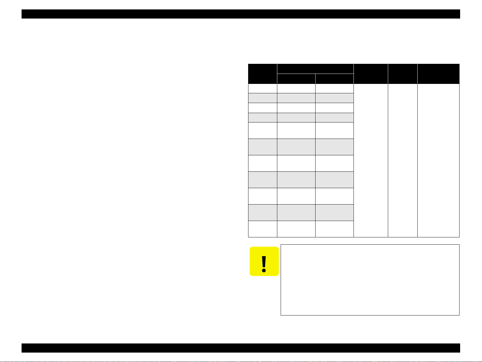
V Stand-alone copy functions
It benefits from using a more recently developed type of ink which enables photoquality copies to be made not only on special media but even on plain p aper. On ly
the basic copy functions are provided for easy operation.
T Paper size can be selected from 2 or 3 options.
Table 1-1. Paper size
Paper size Model
Letter/4"x6" Stylus CX4600
A4/10x15 Stylus CX3500/ CX3600/CX3650/C X4500
T Paper type can be selected from 2 options, plain paper or photo paper, which
also defines copy quality.
T Enlarge / Reduce factor can be selected from 2 options, actual size (100%) or
“Fit to page”.
T Copy margin is automatically selected from 3 options, related to paper type
and paper size. 3mm, “Small Margins Copy”, “Border Free Copy”
T Fast and thick draft mode with the combination of real black and composite
black
T Copy functions can be directly alternated from memory card print functions,
by operation panel. (Only for Stylus CX4500/CX4600)
V Card reader functions (only for Stylus CX4500/CX4600)
This unit includes memory card slots that support CompactFlash, SmartMedia,
Memory Stick, Memory Stick PRO, Micro Drive, SD Memory Card, and xDPicture Card standards.
V Memory card print functions (only for Stylus CX4500/CX4600)
This unit can print images from the memory card in memory card slots in standalone mode.
The memory card print features are as follows.
T Supports “Index sheet printing” whereby images can be selected simply by
marking an index sheet. Selecting images is easy-just check the desired
images and then scan the index sheet.
T Memory card print functions can be directly alternated from copy functions,
by operation panel.
PRODUCT DESCRIPTION Overview 9
EPSON Stylus CX3500/CX3600/CX3650/CX4500/CX4600 Revision A
V Scan functions
This unit provides scan mode so that data can be scanned and transferred to a
connected computer or to e-mail via application software like the EPSON SMART
PANEL.
V Simultaneous use of functions
Printer functions and scanner functions are independent and can therefore be
operated simultaneously from a connected computer.
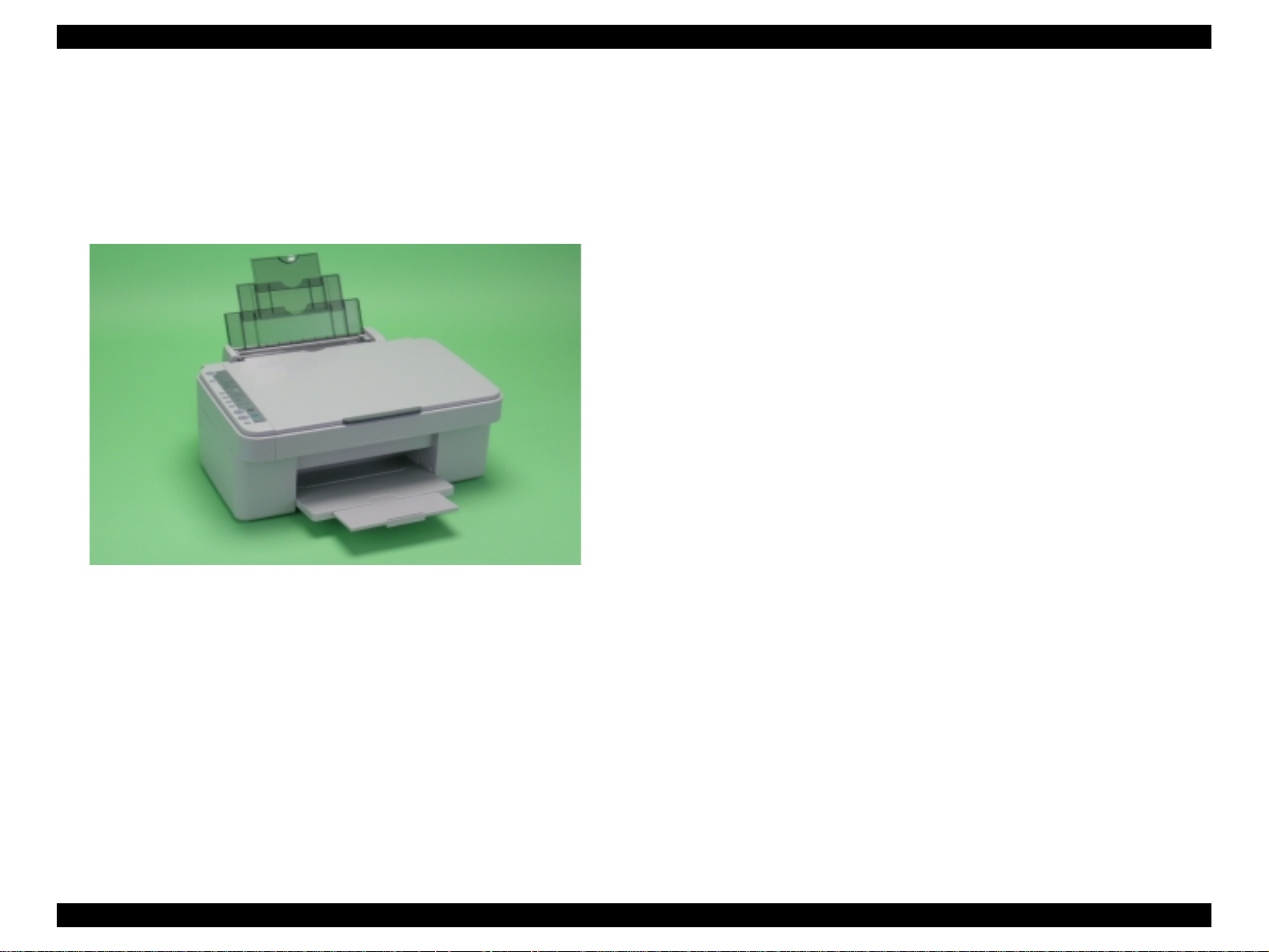
Figure 1-1. Product’s external view
V Easy operation panel
The unit has a simple operation panel equipped with 10 buttons including power
button, LEDs including 7 segment LED and provides basic functions only for
easy operation.
* Card slot model only. (9 buttons for the model without card slot)
V Exterior de sign
Use of a CIS scanner engine has enabled a more compact design.
Also, this unit has operation panel on the left side, which becomes more distinctive
but still easier to use.
PRODUCT DESCRIPTION Overview 10
EPSON Stylus CX3500/CX3600/CX3650/CX4500/CX4600 Revision A
1.2 Specifications
1.2.1 Printer specifications
This section covers specifications of the printer.
1.2.1.1 Physical Specification
V Weight
T Stylus CX3500/CX3600/CX3650 : 6.52kg (without the ink cartridges)
T Stylus CX4500/CX4600 : 6.6kg (without the ink cartridges)
V Dimension (Including rubber feet)
T Printing : 430mm (W) x 500mm (D ) x 2 80mm (H)
T Storage : 430mm (W) x 344mm (D ) x 1 70mm (H )
1.2.1.2 Printing Specification
V Print Method
T On demand i nk jet
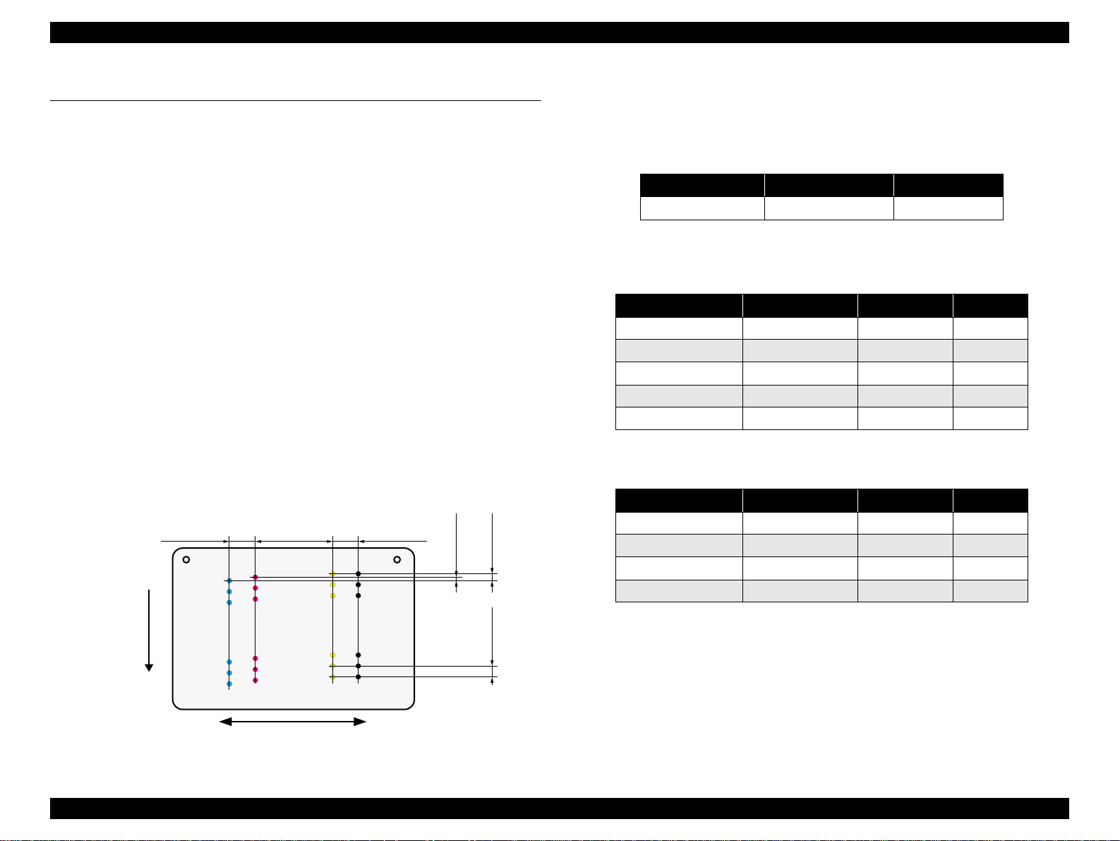
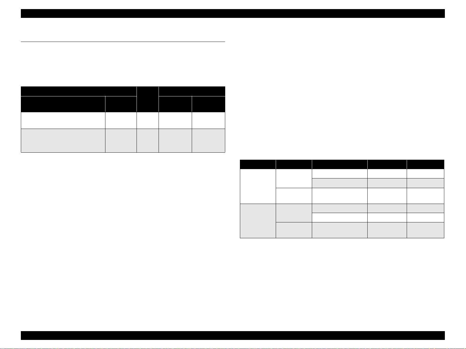
V Nozzle Configuration
T Monochrome 90 nozzles
T Color 90 nozzles x 3 (Cyan, Magenta, Yellow)
Paper Feed Direction
2.822
(40/360inch)
#A90
#A89
#A88
A row B row C row D row
#A3
#A2
#A1
8.467
(120/360inch)
#B90
#C90
#C89
#B89
#C88
#B88
#B3
#B2
#B1
#C3
#C2
#C1
2.822
(40/360inch)
#D90
#D89
#D88
#D3
#D2
#D1
BlackCyan Magenta Yellow
0.1411
0.107055
(1/360inch)
0.2117
V Print Direction
T Bi-directional minimum distance printing (with logic seeking)
V Print Speed & Printable Columns
Table 1-2. Character mode
Character pitch Printable columns CR speed
10 CPI (Pica) 80 285 CPS*
Note "* ": CPS: Characters/Second
This speed is when using normal dot printing mode.
Table 1-3. Graphics mode (standard)
Horizontal resolution Printable area Max. dot count CR speed
360dpi* 209.8mm (8.26") 2976 285cps
360dpi 209.8mm (8.26") 2976 285cps
720dpi 209.8mm (8.26") 5952 285cps
1440dpi 209.8mm (8.26" ) 11904 285cps
2880dpi 209.8mm (8.26") 23808 285cps
Note "*": Draft Printing
Table 1-4. Graphics mode (border-free printing)
Horizontal resolution Printable area Max. dot count CR speed
360dpi* 215.05mm (8.46") 3048 285cps
720dpi 215.05mm (8.46") 6096 285cps
(2/360inch)
1440dpi 215.05mm (8.46") 12192 285cps
2880dpi 215.05mm (8.46") 24384 285cps
Note "* ": Except Draft Printing
(3/360inch)
V Control Code
T ESC/P Raster command
T EPSON Remote command
Carriage Moving Direction
Figure 1-2. Nozzle configuration
PRODUCT DESCRIPTION Specifications 11
EPSON Stylus CX3500/CX3600/CX3650/CX4500/CX4600 Revision A
V Internal fonts
T Character code : Alphanumeric with expanded graphics (PC437)
ASCII, 20H to 7FH only
T Fonts : EPSON original fonts
Alphanumeric font: Courier
V Input buffer size
T 32 Kbytes
1.2.1.3 Paper Feed Specifications
V Paper feed method
Friction feed, using one ASF (Auto Sheet Feeder)
V Paper path
Top feed, front out
V Paper feed rates
T 203.2mm/sec (8.0inch/sec)
: high quality mode, 25.4-mm feed
T 294.64mm/sec (11.6inch/sec)
: high speed mode, continuous feed
V CR interval
Programmable in 0.0176mm (1/1440inch) steps
1.2.1.4 Paper Support
V Cut sheets
Paper size
A4 210mm 297mm
A5 148mm 210mm
A6 105mm 148mm
B5 182mm 257mm
Letter
Legal
Executive
Half Letter
5"x8"
8"x10"
User
defined
89-215.9mm 89-1117.6mm
Dimensions
Width Length
215.9mm
(8.5")
215.9mm
(8.5")
184.2mm
(7.25")
139.7mm
(5.5")
127mm
(5")
203.2mm
(8")
Table 1-5. Cut sheets
Thickness Weight Paper type
279.4mm
(11")
355.6mm
(14")
266.7mm
(10.5")
215.9mm
(8.5")
203.2mm
(8")
254mm
(10")
0.08-0.11mm
64-90g/m
(17-24(lb))
2
Plain paper
Recycled paper
CAUTION
T Poor quality paper may reduce print quality and cause paper
jams or other problems. If you encounter problems, switch to a
higher grade of paper.
T It is necessary that there is no wrinkle, nap, tear, fold, so on in
the form.
T The curve of form must be 5mm or below.
T Use paper under normal conditions
• Temperature 15 to 25°C (59 to 77°F)
• Humidity 40 to 60% RH
PRODUCT DESCRIPTION Specifications 12
EPSON Stylus CX3500/CX3600/CX3650/CX4500/CX4600 Revision A
V Postcards V Envelopes
Table 1-6. Postcards
Paper size
Postcard 100mm 148mm
Return postcard set 200mm 148mm
CAUTION
T Use paper under normal conditions
• Temperature 15 to 25°C (59 to 77°F)
• Humidity 40 to 60% RH
Dimensions
Width Length
T It is necessary that there is no wrinkle, nap, tear, fold, so on in
the form.
T The curve of form must be 5mm or below.
T As for the going and returning postcard, don't use the one with a
fold in the center.
Paper type
Government -s ta ndard postcard
Table 1-7. Enve lopes
Paper size
1
No.10 *
1
DL *
1
C6 *
220x132 *
Tall No.3 *
Tall No.4 *
Western No.1 *
Western No.2 *
Western No.3 *
Western No.4 *
1
2
2
1
1
1
1
Note *1: Check that the flap is on the long edge and can be folded.
*2: Check that the flap is on the short edge and can not be fo ld ed.
CAUTION
T Use paper under normal conditions
Dimensions
Thickness Weight Paper type
Width Length
241.3mm
(9.5")
104.8mm
(4.125")
220mm 110mm
162mm 114mm
220mm 132mm
120mm 235mm
N/A
90mm 205mm
120mm 176mm
114mm 162mm
98mm 148mm
105mm 235mm
• Temperature 15 to 25°C (59 to 77°F)
• Humidity 40 to 60% RH
75-90g/m
(20-24(lb))
75-100g/m
(20-27(lb))
T Poor quality paper may reduce print quality and cause paper
jams or other problems. If you encounter problems, switch to a
higher grade of paper.
T It is necessary that there is no wrinkle, nap, tear, fold, so on in
the form.
T Don't use the adhesive envelopes.
T Don't use sleeve insert envelopes and cellophane window
envelopes.
Bond paper
Air mail
2
PPC
Craft paper
New Kent paper
2
PRODUCT DESCRIPTION Specifications 13
EPSON Stylus CX3500/CX3600/CX3650/CX4500/CX4600 Revision A
V Exclusive papers
Quality: EPSON Exclusive paper
Transparency printing is only available at normal temperature.
T Stylus CX4600
Table 1-8. Exclusive papers
Item Size
Glossy Photo Paper *
Matte Paper Heavy
Weight *
DURABrite Ink Glossy
Photo Paper
Double Sided Matte
Paper *
Note "*": Not supported with stand-alone functions of copy and memory card print.
CAUTION
T Use paper under normal conditions.
Letter 215.9 279.4
4"x6" 101.6 152.4
Letter 215.9 279.4
8"x10" 203.2 254
Letter 215.9 279.4
4"x6" 101.6 152.4
Letter 215.9 279.4 0.25 178
• Temperature 15 to 25°C (59 to 77°F)
• Humidity 40 to 60% RH
Width
(mm)
Length
(mm)
Thickness
(mm)
0.23 188
0.23 167
0.21 206
T Poor quality paper may reduce print quality and cause paper
jams or other problems. If you encounter problems, switch to a
higher grade of paper.
T It is necessary that there is no wrinkle, nap, tear, fold, so on in
the form.
T The curve of form must be 5mm or below.
Weight
2
(g/m
T Stylus CX3500/CX3600/CX3650/CX4500
Table 1-9. Exclusive papers
Item Size
Photo Paper * A4 210 297 0.23 188
A4 210 297
)
Photo Quality Ink Jet
Paper *
Matte Paper Heavy
Weight *
DURABrite Photo
Paper
Premium Semigloss
Photo Paper *
Archival Matte Paper * A4 210 297 0.25 189
Double Sided Matte
Paper *
Note "*": Not suppo rted with stand-alone functions of copy and memory card print.
CAUTION
T Use paper under normal conditions.
• Temperature 15 to 25°C (59 to 77°F)
• Humidity 40 to 60% RH
A6 105 148
5"x8" 127 203.2
8"x10" 203.2 254
A4 210 297
8"x10" 203.2 254
A4 210 297
10cmx15cm 101.6 152.4
A4 210 297 0.27 250
A4 210 297 0.25 178
Width
(mm)
Length
(mm)
Thickness
(mm)
0.13 102
0.23 167
0.21 206
Weight
2
(g/m
)
T Poor quality paper may reduce print quality and cause paper
jams or other problems. If you encounter problems, switch to a
higher grade of paper.
T It is necessary that there is no wrinkle, nap, tear, fold, so on in
the form.
T The curve of form must be 5mm or below.
PRODUCT DESCRIPTION Specifications 14
EPSON Stylus CX3500/CX3600/CX3650/CX4500/CX4600 Revision A
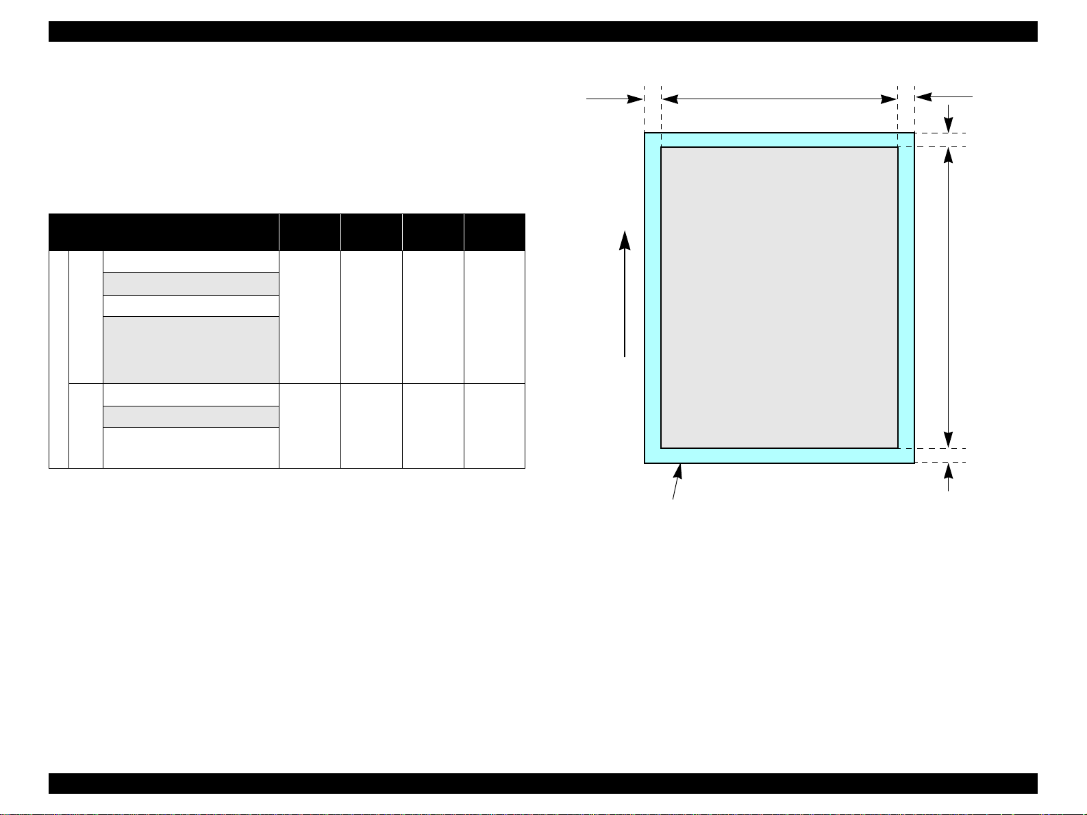
1.2.1.5 Printing Area
V Cut sheet (standard printing)
T Printable area
The print quality is guaranteed for the print area above the 3 mm bottom
margin. For paper width (PW) and paper length (PL), refer to “1.2.1.4 Paper
Support” (p.12).
Refer to the following table. As for each margin area, refer to Figure 1-3
(p.15).
Table 1-10. Applicable paper/Printing area
Paper type
A4
A5
A6
B5
Letter
Legal
Executive
Cut sheets
Half Letter
5"x8"
8"x10"
User defined
Postcard
Post
cards
Return postcard set
Photo Paper
Photo Quality In k Jet Paper
Matte Paper Heavy Weight
DURABrite Photo Paper
Premium Semigloss Photo Paper
Exclusive pa pers
CX3650/CX4500
Archival Matte Paper
Stylus CX3500/CX3 600/
Double Sided Matte Paper
Left
margin
3 mm
(0.12")
3 mm
(0.12")
3 mm
(0.12")
Right
margin
3 mm
(0.12")
3 mm
(0.12")
3 mm
(0.12")
Top
margin
3 mm
(0.12")
3 mm
(0.12")
3 mm
(0.12")
Bottom
margin
3 mm
(0.12")
3 mm
(0.12")
3 mm
(0.12")
Paper type
Glossy Photo Paper
Matte Paper Heavy Weight
DURABrite Ink Glossy Photo
Paper
Stylus CX4600
Exclusive papers
Double Sided Matte Paper
LM
Paper Feed Direction
Figure 1-3. Printable area Cut sheet (standard printing)
Table 1-10. Applicable paper/Printing area
Left
margin
3 mm
(0.12")
Right
margin
3 mm
(0.12")
PW
Printable area
Top
margin
3 mm
(0.12")
RM
TM
BM
Bottom
margin
3 mm
(0.12")
PL
PRODUCT DESCRIPTION Specifications 15
EPSON Stylus CX3500/CX3600/CX3650/CX4500/CX4600 Revision A
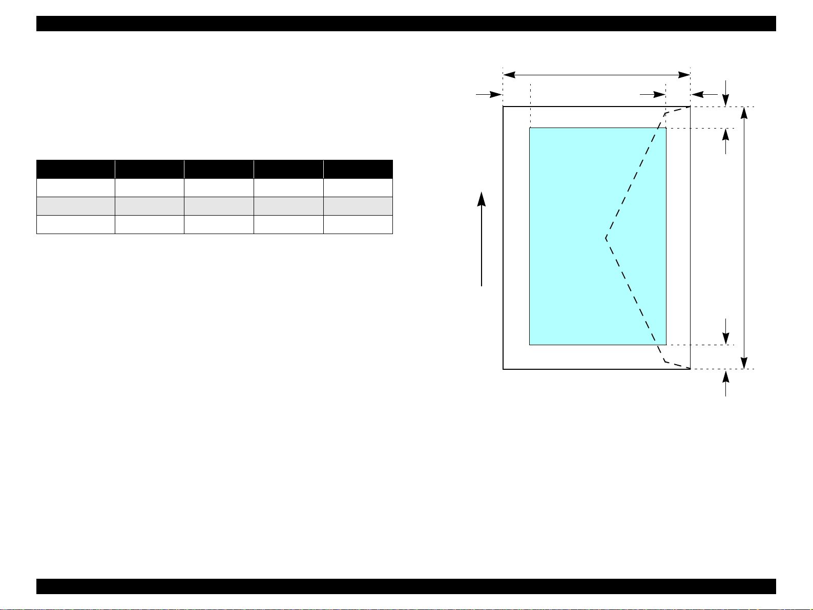
V Cut sheet (border-free printing)
T Printable area
For paper width (PW) and paper leng th (PL), refer to “1.2.1.4 Paper Support”
(p.12).
Refer to the following table. As for each overhang area, refer to Figure 1-4
(p.16).
Table 1-11. Applicable paper/Printing area
Paper type
Photo Paper
Matte Paper Heavy Weight
DURABrite Photo Paper
Premium Semigloss Photo Paper
CX3650/CX4500
Stylus CX3500/CX3 600/
Exclusive paper
Glossy Photo Paper
Matte Paper Heavy Weight
DURABrite Ink Glossy Photo
Paper
Stylus CX4600
Left
Overhang
2.5 mm
(0.09")
2.5 mm
(0.09")
Right
Overhang
2.5 mm
(0.09")
2.5 mm
(0.09")
Top
Overhang
3 mm
(0.12")
3 mm
(0.12")
Bottom
Overhang
5 mm
(0.2")
5 mm
(0.2")
LO ROPW
Paper size
Paper Feed Direction
TO
PL
BO
Printable area
Figure 1-4. Printable area for Cut sheet (border-free printing)
PRODUCT DESCRIPTION Specifications 16
EPSON Stylus CX3500/CX3600/CX3650/CX4500/CX4600 Revision A
V Envelopes
T Printable area
For paper width (PW) and paper leng th (PL), refer to “1.2.1.4 Paper Support”
(p.12).
Refer to the following table. As for each margin area, refer to Figure 1-5
(p.17).
Table 1-12. Applicable paper/Printing area
Paper type Left Margin Right Margin Top Margin Bottom Margin
No.10 3mm (0.12") 3mm (0.12") 3mm (0.12") 20mm (0.79 ")
DL 3mm (0. 12") 3mm (0.12") 3mm (0.12") 20mm (0.79")
C6 3mm (0.12") 3mm (0.12") 3mm (0.12") 20mm (0.79")
PL
LM
RM
TM
Printable area
PW
Paper Feed Direction
BM
Figure 1-5. Printable area for envelopes
PRODUCT DESCRIPTION Specifications 17
EPSON Stylus CX3500/CX3600/CX3650/CX4500/CX4600 Revision A
1.2.1.6 Ink Cartridge Specification
V Type/color : EPSON-brand special ink cartridges
Table 1-13. Ink Cartridge
Color Size
Black S size T0441 T0461
Cyan
Magenta
Yellow
Note "*": Except Stylus CX4600.
S size T0442 —
SS size T0452 * T0472
S size T0443 —
SS size T0453 * T0473
S size T0444 —
SS size T0454 * T0474
V Print Capacity
T Black Ink Cartridge : 400 pages/A4
T Color Ink Cartridge
• S size : 450 pages/A4 (360x720 dpi, 5% duty for each color)
• SS size : 260 pages/A4 (360x720 dpi , 5% duty for each color)
V Shelf life : After packing is opened, it is assumed 6 months, and
V Storage Temperature
Stylus CX3500/CX3600/
CX3650/CX4600
Stylus CX3500/CX4500
(ISO/IEC10561 Letter Pattern at 360x720 dpi)
380 pages/A4
(360x720 dpi, 5% duty)
assumes 2 years including this.
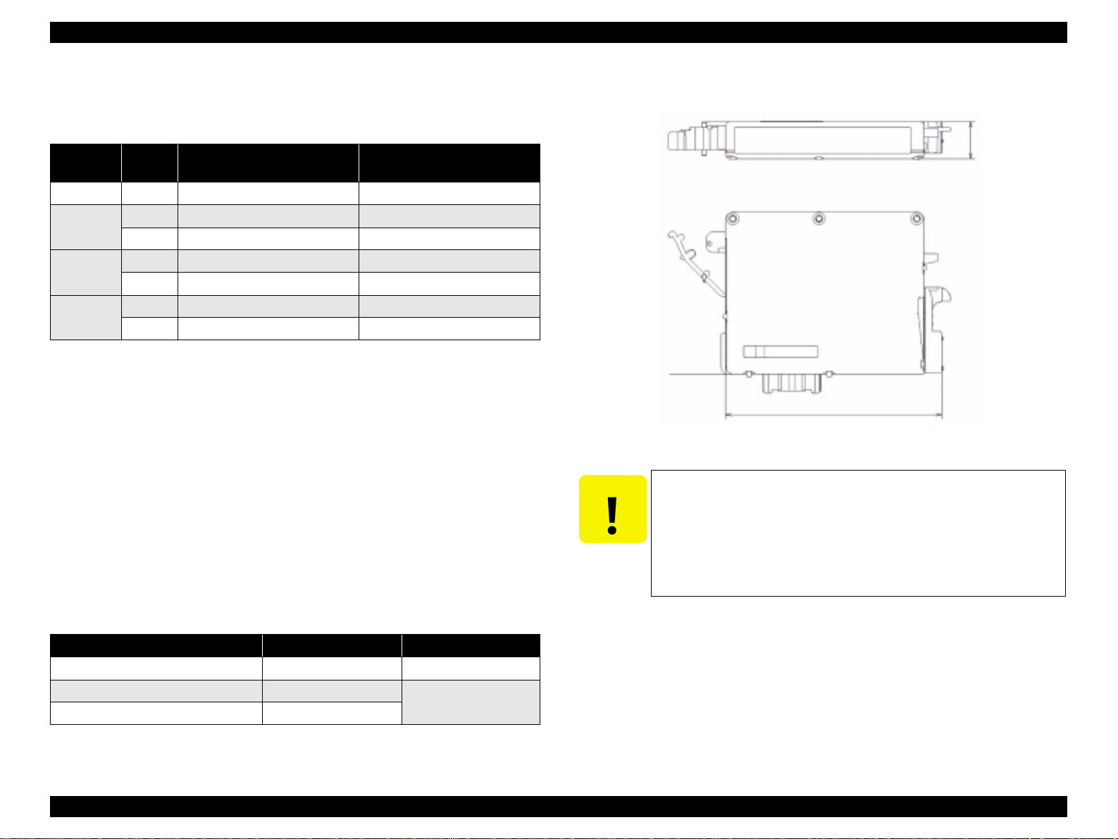
V Dimension : 12.7mm (W) x 73.46mm (D) x 55.25mm (H)
Base View
73.46mm
Figure 1-6. Ink cartridge
CAUTION
T The ink cartridge cannot be refilled.
T The ink cartridge that passes the expiration date should not be
used.
T The ink in the ink cartridge freezes when leaving it in the
environment of -16 °C or under. It takes 3 hours that the frozen
ink becomes usable when moving it from the environment of -20
°C to the environment of 25 °C.
12.7mm
Table 1-14. Storage Temperature
Situation Storage Temper ature Limit
o
When transported in individual boxes -30
When stored in individual boxes -30 oC to 40 oC
When installed in main unit -20 oC to 40 oC
C to 50 oC 10 days max. at 50 oC
1 month max. at 40 oC
PRODUCT DESCRIPTION Specifications 18
EPSON Stylus CX3500/CX3600/CX3650/CX4500/CX4600 Revision A
1.2.2 Scanner specifications
This section covers specifications of the scanner.
1.2.2.1 Basic Specifications
V Product type : Flatbed color image scanner
V Scanning method : Scanning of fixed document wit h mobile scan head
V Sensor : CIS
V Maximum scan area : 8.5" x 11.7" (216 mm x 297 mm)
V Document sizes : A4 or US letter
V Max. effective pixels : 5,100 x 7,020 pixels (600 dpi)
V Resolution
T Main scan : 600 dpi
T Sub scan : 1200 dpi with Micro Step
V Scanning resolution : 50 to 4800 dpi (selectable in 1-dpi steps), 7200 dpi,
9600 dpi
V Gradations (pixel depth) : Each color pixel has 16-bit input and either 1-bit or 8-
bit output.
V Scanning speed : 600 dpi
T Color : Approx. 15 msec/line
1.2.2.3 Image scanning area
Table 1-15. Image scanning area
RW
(readable width)
216 mm (8.5") 1.5 mm ± 1 mm 297 mm (11.7") 1.5 mm ± 1 mm
OLM
(out-of-range left margin)
Original's top left alignment position
OLM
First pixel
Scan direction
RL
(readable length)
(out-of-range top margin)
a
RW
RLOTM
OTM
Original
(face down)
Scan bed
Scan area
T Monochrome : Approx. 5 msec/line
V Light source : RGB Three Color LED
Figure 1-7. Image scanning area
1.2.2.2 Detailed Specifications
V Control commands : ESC/I D7
V Gamma correction : Two user-defined levels
PRODUCT DESCRIPTION Specifications 19
EPSON Stylus CX3500/CX3600/CX3650/CX4500/CX4600 Revision A
1.2.3 Common
1.2.3.1 Electric Specification
V Primary power input
Table 1-16. Primary power input
100-120V model 220-240V mo del
Rated power su pply volta ge (A CV) 100 ~ 120 220 ~ 240
Input voltage range (ACV) 90 ~ 132 198 ~ 240
0.4A
Rated current (A)
Rated frequency (Hz) 50 ~ 60
Input frequency range (Hz) 49.5 ~ 60.5
Power consumption (W)
(max. 0.6A w/ card slot model)
(max. 0.7A w/o card slot model)
Approx. 11W (w/ card slot model)
Approx. 12W (w/o ca rd slot model)
(Standalone copying, ISO10561 Lett er Patter, Plain
Paper - Text)
Approx. 2.5W (Lowe-power Mode/Sleep Mode)
Approx. 0.2W
(Power Off Mode)
0.2A (max. 0.3A)
Approx. 0.4W
(Power Off Mode)
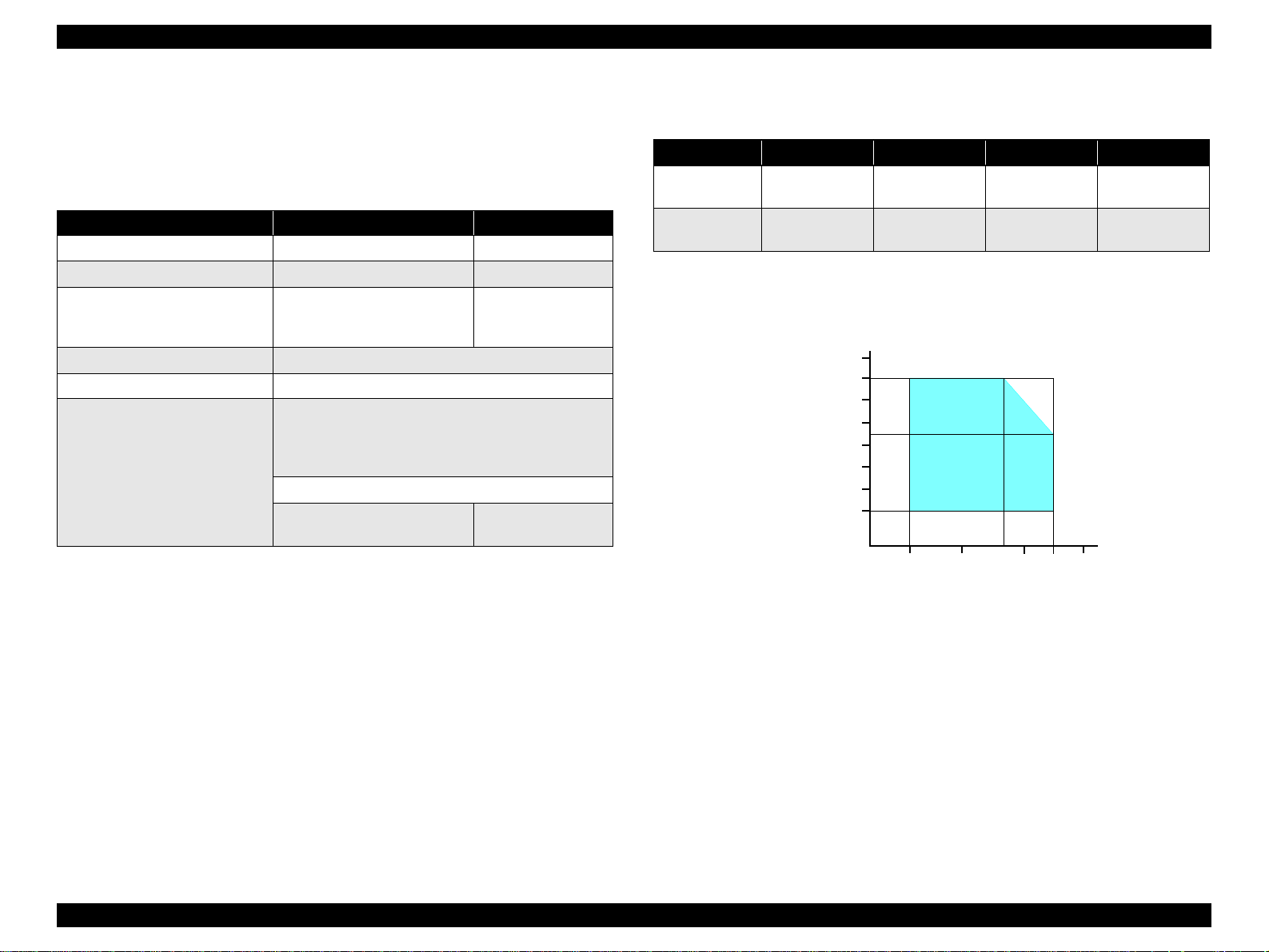
1.2.3.2 Environmental Performance
Table 1-17. Environmental Performance
Condition Temperature Humidity *
3
Operating 10 ~ 35°C *
Not operating *
Note *1: After unpacking (storage)
*2: No cond ensation
*3 : Under the following conditions
1
-20 ~ 40°C 5 ~ 85%
Humidity (%)
90
80
70
60
50
40
30
20
20 ~ 80% *
2
3
Impact Vibration
1G,
-3
1 x 10
seconds
2G,
-3
2 x 10
seconds
0.15G
0.50G
Note 1: This product complies with the “Ener gy Star” standards.
27
10
20
35 40
30
Temperature (°C)
2: If the printer is not operated at all for at least five minutes, the standby function reduces
the current to the motor to conserve power.
3: If the scanner is not operated at all for at least five minutes, the standby function
reduces the current to the motor to conserve power.
V Insulation resistance
10MΩ minimum (tested betw een AC line and chassis, test voltage: DC500V)
V Dielectric strength
T AC1000 Vrms for one minute or AC1200 Vrms for one second
(100-120V version)
T AC1500 Vrms for one minute (220-240V version)
1.2.3.3 Durability
V Total print life : 10,000 pages (black only, A4), or 5 years (whichever
V Print Head Life : 3 billion shots (per nozzle) or 5 years (whichever
V Scanner head : MCBF (30,000 cycles)
Figure 1-8. Temperature/Humidity range
comes first)
comes first)
PRODUCT DESCRIPTION Specifications 20
EPSON Stylus CX3500/CX3600/CX3650/CX4500/CX4600 Revision A
1.2.3.4 Safety Standards: EMC
Table 1-18. Safety Standards: EMC
100-120V version 220-240V ver si on
Safety standards
EMI
UL60950
CSA22.2 No.60950
FCC part15 subpart B class B EN 55022(CISPR Pub.22) class B
CSA C108.8 class B AS/NZS 3548 class B
EN 60950
1.2.3.5 Acoustic Noise
V Noise level
45dB (max.) (according to ISO7779 when for copying)
1.2.3.6 CE Marking
V 220-240 V version
T Low Voltage Directive 73/23/EEC : EN60950
T EMC Directive 89/336/EEC : EN55022 Class B
EN61000-3-2
EN61000-3-3
EN55024
PRODUCT DESCRIPTION Specifications 21
EPSON Stylus CX3500/CX3600/CX3650/CX4500/CX4600 Revision A
1.3 Interface
The EPSON Stylus CX3500/CX3600/CX3650/CX4500/CX4600 provides the
following interface.
1.3.1 USB Interface
V Standards
T “Universal Serial Bus Specifications Revision 2.0”
T “Universal Serial Bus Device Class Definition for Printing Devices Version
1.1” (printer unit)
T “Universal Serial Bus Mass Storage Class Bulk-Only Transport Revision 1.0”
(storage unit)
V Transfer rate : 12 Mbps (Full Speed Device)
V Data format : NRZI
V Compatible connector : USB Series B
V Recommended cable length : 2 [m] or less
V Device ID
Table 1-19. Device ID
Model
Name
Stylus
CX3500
Stylus
CX3600
Stylus
CX3650
Device ID
[00H][54H]
MFG:EPSON;
CMD:ESCPL2,BDC,D4;
MDL:Stylus[SP]CXxxxx;
CLS:PRINTER;
DES:EPSON[SP]Stylus[SP]CX3500;
[00H][54H]
MFG:EPSON;
CMD:ESCPL2,BDC,D4;
MDL:Stylus[SP]CXxxxx;
CLS:PRINTER;
DES:EPSON[SP]Stylus[SP]CX3600;
[00H][54H]
MFG:EPSON;
CMD:ESCPL2,BDC,D4;
MDL:Stylus[SP]CXxxxx;
CLS:PRINTER;
DES:EPSON[SP]Stylus[SP]CX3600;
Model
Name
Stylus
CX4500
Stylus
CX4600
Device ID
[00H][54H]
MFG:EPSON;
CMD:ESCPL2,BDC,D4;
MDL:Stylus[SP]CXxxxx;
CLS:PRINTER;
DES:EPSON[SP]Stylus[SP]CX4500;
[00H][54H]
MFG:EPSON;
CMD:ESCPL2,BDC,D4;
MDL:Stylus[SP]CXxxxx;
CLS:PRINTER;
DES:EPSON[SP]Stylus[SP]CX4600;
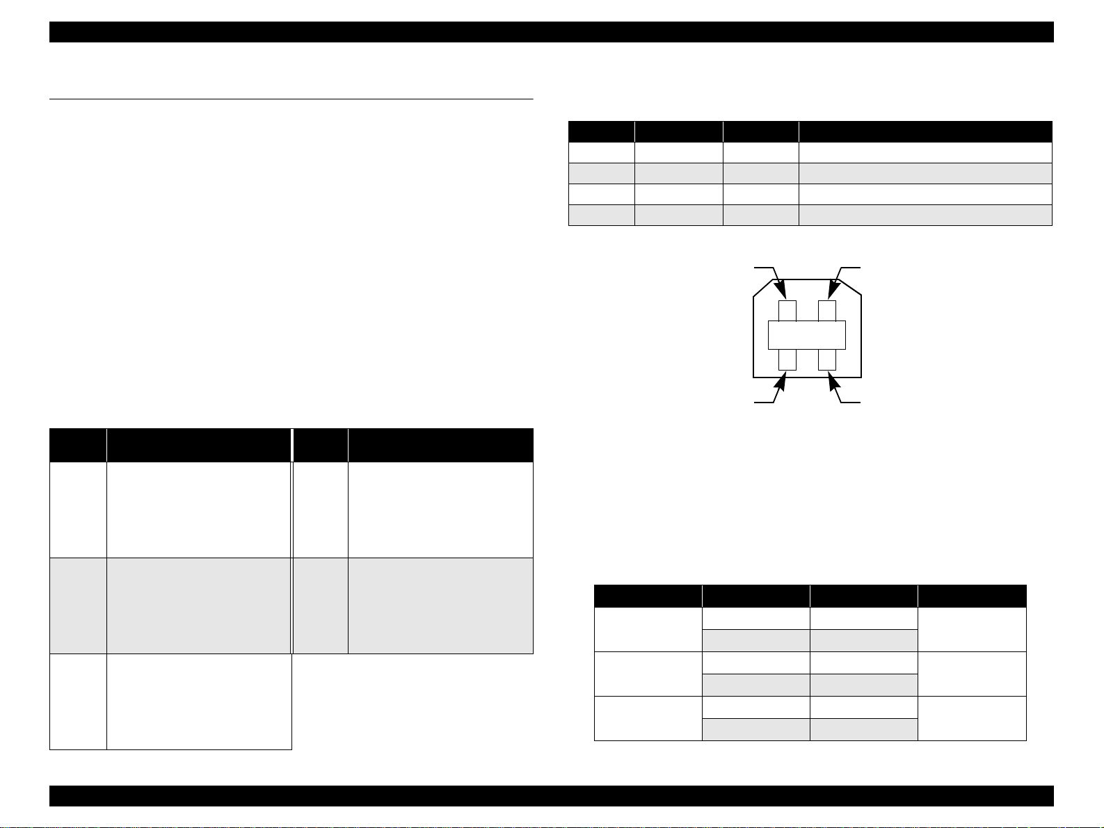
V Connector signal layout
Table 1-20. Connector pin assignment and signals
Pin No. Si gn al na me I/O Function desc ription
1 VCC - Cable power. Max. power c onsumption is 2mA.
2 -Data Bi-D Data
3 +Data Bi-D Data, pull up to +3.3V via 1.5K ohm resistor.
4 Ground - Cable ground
Pin #2
Pin #3
Pin #1
Pin #4
Figure 1-9. USB pin Assignment
V Product ID
T 0x080D (Stylus CX4500/CX4600)
T 0x080E (Stylus CX3500/CX3600/CX3650)
V Endpoint attribute
Table 1-21. Endpoint attrib ute
I/F No. Endpoint Addr e ss Endpoint Type Linked Interface
0x00
0x01
0x02
0x01 Bulk In
0x02 Bulk Out
0x03 Bulk In
0x04 Bulk Out
0x05 Bulk In
0x06 Bulk Out
Scanner
Printer
Card
PRODUCT DESCRIPTION Interface 2 2
EPSON Stylus CX3500/CX3600/CX3650/CX4500/CX4600 Revision A
1.3.2 Standard Card Slots (only for Stylus CX4500/CX4600)
1.3.2.1 Memory card
Table 1-22. Memory card
Memory card standa rd s Slots Supported memory c ar ds
Compact
Flash
SmartMedia
Memory
Stick
Memory
Stick PRO
SD
MultiMedia
Card
xD-Picture
Card
CF+ and CompactFlash
Specification Revision 1.4
compliant
SmartMedia Standard 2000
compliant
MemoryStick Standard version
1.3 compliant
MemoryStick Standard Memory
Stick PRO Format Spec ifications
version 1.0 compliant
SD Memory Card Specifications
/ PART1. Physical Layer
Specification Version 1.0
compliant
MultiMediaCard Standard
compliant
TM
xD-Picture Card
Specification Version 1.00
compliant
Card
CF Type II slot
SmartMedia slot
Memory Stick/
Memory Stick
PRO slot
SD/MMC slot
xD-Picture Card
slot
• Compact Flash
(memory car d onl y )
•Microdrive
Smart Media
(maximum capaci ty: 128 MB)
• Memory Stick
(maximum capacity: 128 MB,
including versions with memory
select function)
• MagicGate Memory Stick
(maximum capacity: 128 MB,
copy protection func tio n is not
supported)
• Memory Stick Duo
(requires Memory Stick Duo
adapter)
• Memory Stick Duo
(requires Memory Stick Duo
adapter)
• Memory Stick PRO Duo
• (requires Memory Stick Duo
adapter)
• SD (Secure Digital) memory
card
• miniSD card
(requires SD adapter)
MultiMediaCard
xD-Picture Card
CAUTION
Note the following caution points when handling the memory card.
T Since the SD card and Memory Stick share the same slot, only
one can be inserted at a time.
T Since the SmartMedia and xD-Picture Card share the same slot,
only one can be inserted at a time.
T When a memory card is being accessed, be sure to keep the
memory card slot's cover closed and do not touch the memory
card.
1.3.2.2 Supported power supply voltage
V 3.3V/5V (both)
V 3.3V (only)
NOTE 1: 3.3V power is supplied to media that support both 3.3V and 5V.
2: Maximum current to memory card is 500mA.
3: 5V type memory cards are not supported.
PRODUCT DESCRIPTION Interface 2 3

EPSON Stylus CX3500/CX3600/CX3650/CX4500/CX4600 Revision A
1.3.2.3 Multi-slot operations
V Overview
T There is only one type of card that can be used to simultaneously access both
a connected computer and the direct printing function.
T The slots have assigned priority to determine which slot will be accessed first
when cards are inserted in several slots at once.
T To select a card that has been inserted in a non-active slot, the card in the
active slot must first be removed.
• Direct printing:
Only the image files in the active slot are valid and have assigned frame
numbers. The number of images will not change if a card is also inserted in
a non-selected slot.
• Connection to computer (Windows):
Only one drive is displayed at a time as a “removable disk” and only the
card that is in the active slot can be accessed via the removable disk. A card
that has been inserted into a non-selected slot cannot be accessed.
• Connection to computer (Macintosh):
Only the card in the active slot can be mounted on the desktop. A card that
has been inserted into a non-selected slot canno t be mo unted on the des ktop.
V Details
T Access priority
The access priority among slots is assigned as:
1: CF (Micro Drive)
2: Smart Media
3: Memory Stick (Memory Stick PRO)
4: SD (MMC)
5: xD-Picture Card
T Slot selection when power is turned on
If cards are inserted in several slots when the power is turned on, the active
slot is determined by the priority ranks listed above.
Example: If Smart Media and Memory Stick are both inserted at power-on,
the Smart Media slot becomes the active slot.
T Slot selection after power is turned on
When a card is removed from the active slot, the slot with the next-highest
priority becomes the active slot (if a card has been inserted in to it). There is no
need to re-insert any card befor e accessing it. If no slots contain any car ds, the
highest-priority slot (CF Micro Drive) again becomes the active slot.
Cards can be removed from non-selected slots in any order.
Example: If a memory stick and CF card are inserted while Smart Media is
selected, CF becomes selected (active) once Smart Media is
removed.
PRODUCT DESCRIPTION Interface 2 4
EPSON Stylus CX3500/CX3600/CX3650/CX4500/CX4600 Revision A
1.4 Stand-alone Copy
1.4.1 Basic Specifications
1.4.1.1 Supported paper sizes, types and qualities
Table 1-23. Supported paper sizes, types and qualities
Paper type
Paper name
Plain Paper
Recycled Paper
DURABright Photo Paper
(DURABright I nk Glo ssy Ph oto Pa per )
Note : The quality of draft copy is not affected by “Paper type” selection.
Note *1: C onnected with Paper t ype.
*2: Paper si zes in parentheses app ly only to Stylus CX4600.
Panel
Indication
Plain Paper
Photo Paper
Quality
1
*
Plain
Paper
Photo
Paper
Paper size *
Paper size
A4
(Letter)
A4 (Letter),
10cm x 15cm
(4" x 6")
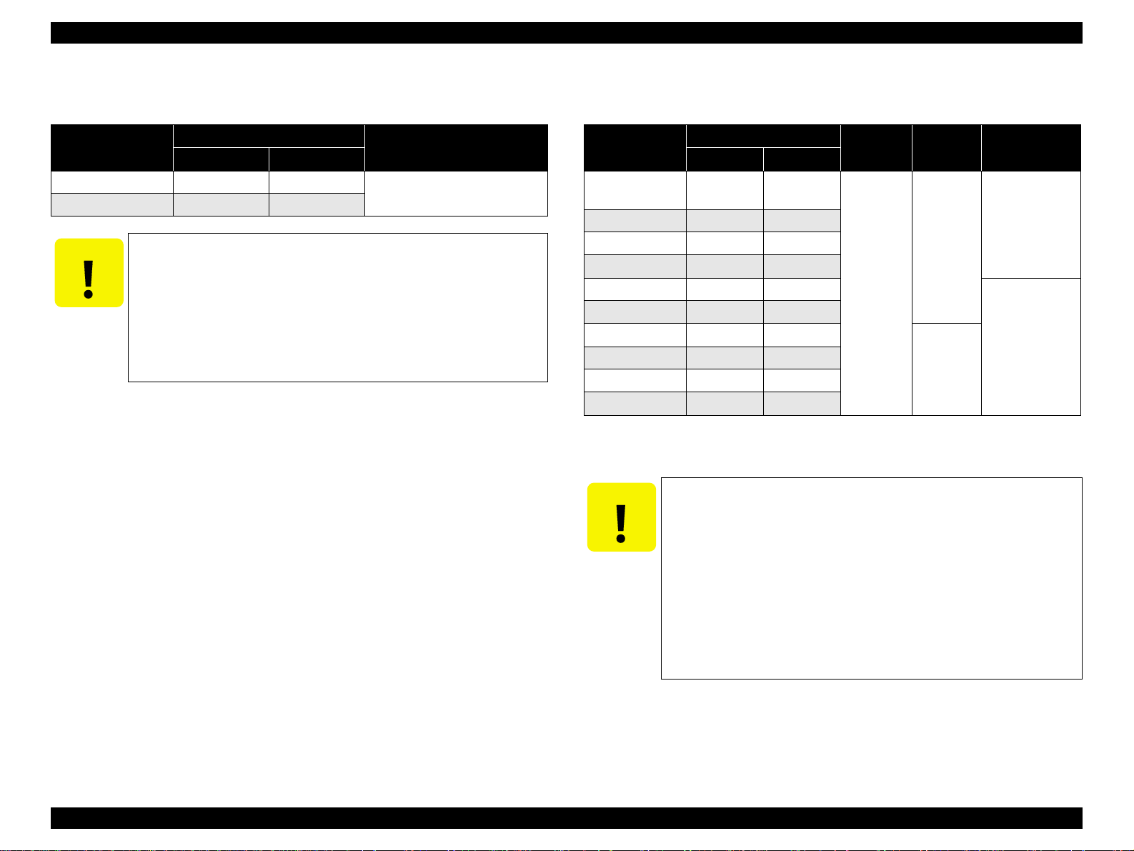
1.4.1.2 Zoom function
The zoom function provides enlarged or reduced copies of originals. The either of the
following can be selected from the operation panel.
V Actual (The state which “Fit to page” is not selected. It is the power-on default.)
The zoom factor is set to 100%.
V Fit to page
This function detects the image size of the original and automatically sets the
zoom factor of the copy according to the copy paper's printable area.
1.4.1.3 Number of copies setting
This function sets the number of copies. The setting range is 1 to 9 and 100.
1.4.1.4 Maximum copy size
V 216 x 297mm
2
Panel
Indication
A4
(Letter)
A4 (Letter),
10cm x 15cm
(4" x 6")
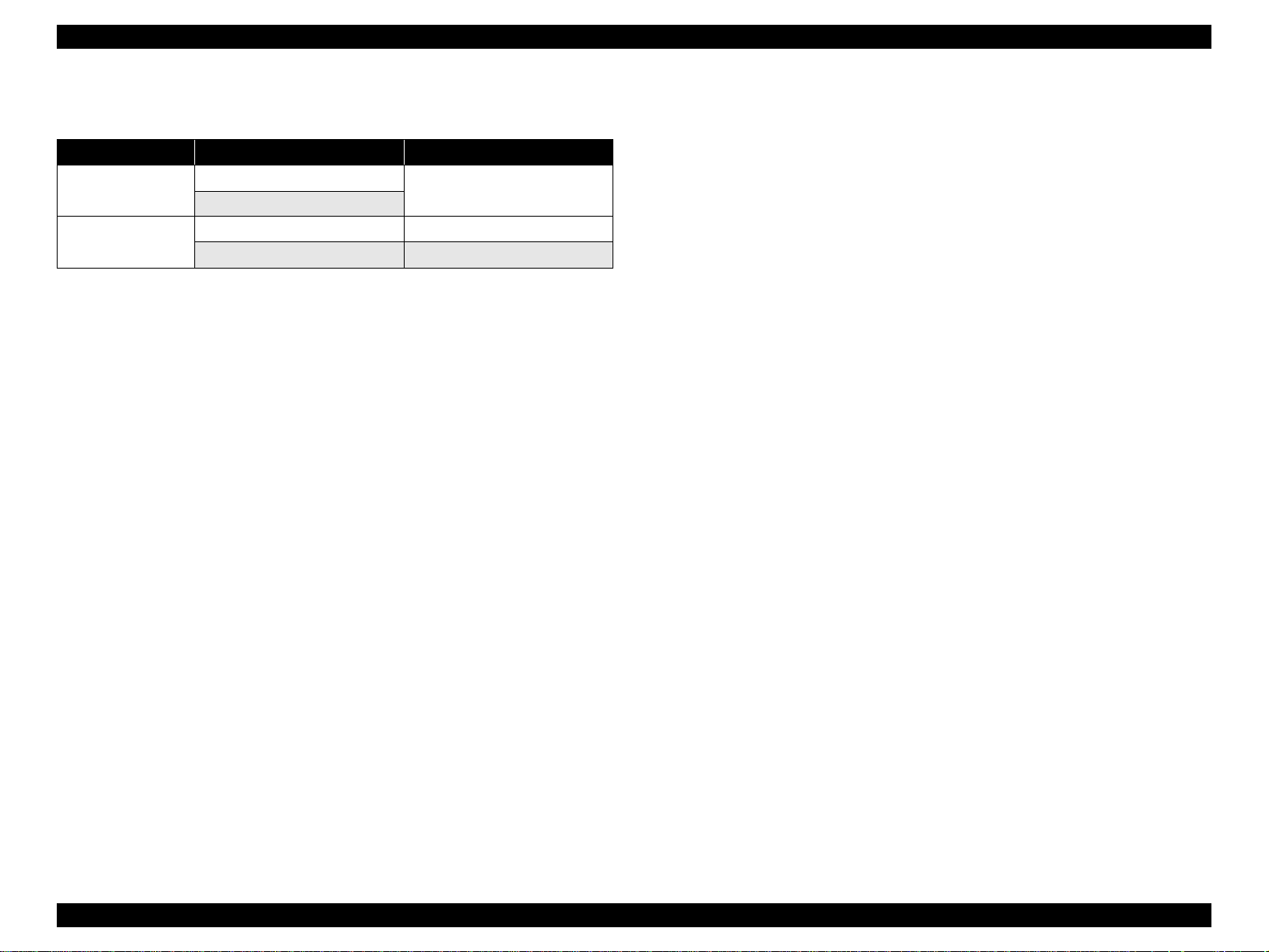
1.4.1.5 Copy layout
The following copy layout is provided according to “Paper type”, “Paper size” and
zoom selections.
V Standard copy
Provided for ordinary use with 3mm copy margin from every side.
V BorderFree copy
Border-free printing of copies occurs when the print area is set as larger than the
copy paper's size. In such cases, the outer edges of the original image may be
omitted in the printed copy.
V Small Margins copy
This function sets a 1. 5mm margin on all four sides when pr inting in order to mak e
maximum use of the original image and copy paper.
NOTE: Only “Standard Copy” can be used in draft copy mode.
Table 1-24. Copy layout
Zoom Paper type Paper size *
Plain Paper
Actual *
Fit to page *
Note *1 : Actual is the state that “Fit to page” is not selected.
1
Photo Paper
Plain Paper
2
Photo Paper
*2 : “Fit to page” automatically sets the enlarge/reduce scale so that the entire image fits
into the printable area or the border free area when border free layout is selected.
When the original image is smaller than general card size (approx. 54mm x 86mm),
the print margins will be different from the one that is defined by each layout.
The image placement uses the upper left corner as the origin and any margins that
occur during the fitting process occur along the bottom and/or right edge.
*3: Pape r sizes in parentheses apply only to Stylus CX4600.
A4 (Letter) B&W, Color Standard
10cm x 15cm (4" x 6") B&W, Color Standard
A4 (Letter),
10cm x 15cm (4" x 6")
A4 (Letter) B&W, Color Standard
10cm x 15cm (4" x 6") B&W, Color Standard
A4 (Letter),
10cm x 15cm (4" x 6")
3
B&W / Color Layout
B&W, Color Small margin
B&W, Color Border free
PRODUCT DESCRIPTION Stand-alone Copy 25
EPSON Stylus CX3500/CX3600/CX3650/CX4500/CX4600 Revision A
1.4.1.6 Multiple copies from an original
Second and subsequent copies can be printed from an original without scanning.
When printing two or more copies, under the following settings the scan data can be
stored in the unit's memory so that the second and subsequent copies can be printed
without scanning.
V “Draft” mode (monochrome/color)
V “Text” mode (monochrome)
1.4.2 Copy Speed
1.4.2.1 Black Copy Speed
V Plain Paper – Draft 12.6 cpm (Copy per minute), Plain Paper – 3.1 cpm
V Black e-Memo text A4 size pattern, zoom 100%
The above speed is for the second and subsequent copies (the time between
ejection of the first page to ejection of the second page).
1.4.2.2 Color Copy Speed
V Plain Paper – Draft 11.6 cpm (Copy per minute)
V Color e-Memo text A4 size pattern, zoom 100%
The above speed is for the second and subsequent copies (the time between
ejection of the first page to ejection of the second page)
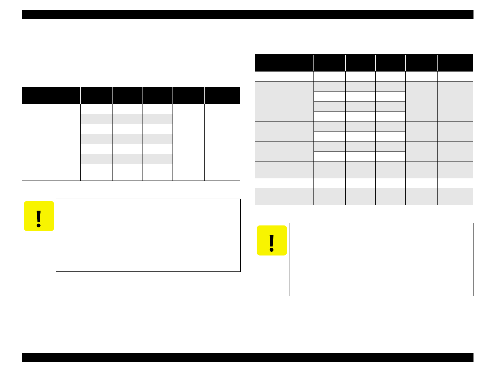
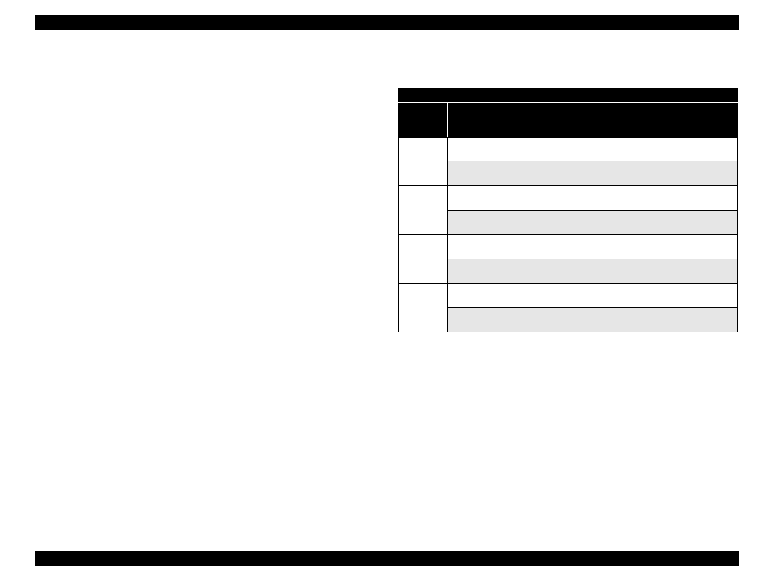
1.4.3 Configuration for copying
Table 1-25. Configuration for copying
Copy Mode setting Scan and Print configuration
Paper type
Plain Paper
Photo Paper
(A4/Letter)
Photo Paper
(smaller than
A4/Letter)
Draft (Plain
paper only)
B&W /
Color
B&W
Color
B&W
Color
B&W
Color
B&W
Color
Enlarge /
Reduce*
(%)
100
(Default)
100
(Default)
100
(Default)
100
(Default)
100
(Default)
100
(Default)
100
(Default)
100
(Default)
Note *1 : “Default” is the state in which “Fit to page” is not selected. When “Fit to page” is
selected, scan resolution will be optimized according to enla rge/ reduce scale.
*2: With “Photo Paper”, composite black will be used in both B&W and color mode.
*3: With “Draft”, both real black and composite black will be used for black printing.
“PEC” technology will be used.
*4 : “PEC” technology will be used for A4 or Letter size printing.
Scan
1
resolution*
(M x S dpi)
600 x 300 360 x 360 VSD1 Off On C1
300 x 600 360 x 720 VSD1 On On C1
600 x 600 720 x 1440*
600 x 600 720 x 1440*4VSD3 On On C2
600 x 600 720 x 1440 VSD3 On On C3
600 x 600 720 x 1440 VSD3 On On C3
300 x 100 360 x 120 VSD1 Off On C4
300 x 100 360 x 120 VSD1 Off On C4
1
(H x V dpi)
Print
resolution
Dot size MW
4
VSD3 On On C2
High
Speed
LUT
PRODUCT DESCRIPTION Stand-alone Copy 26
EPSON Stylus CX3500/CX3600/CX3650/CX4500/CX4600 Revision A
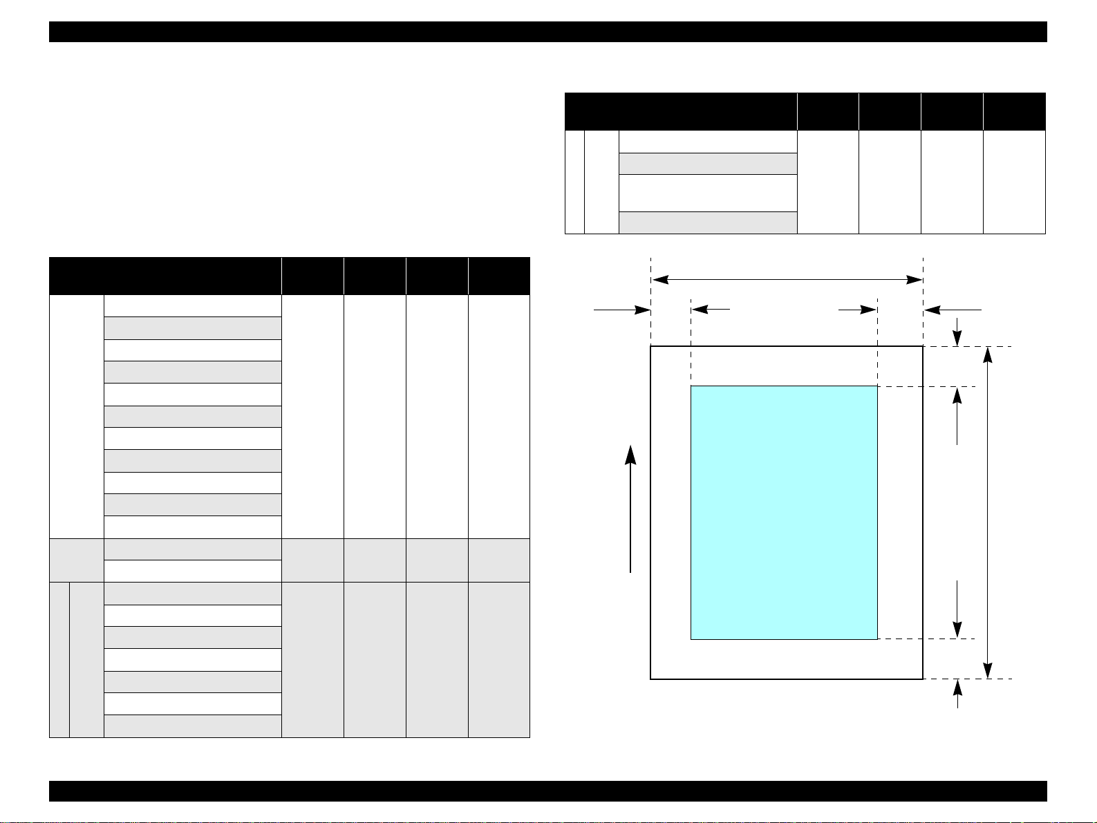
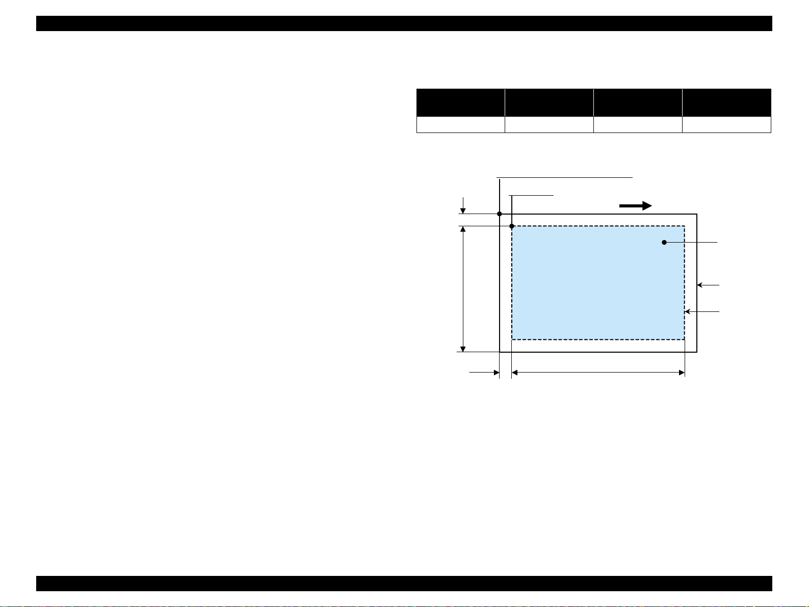
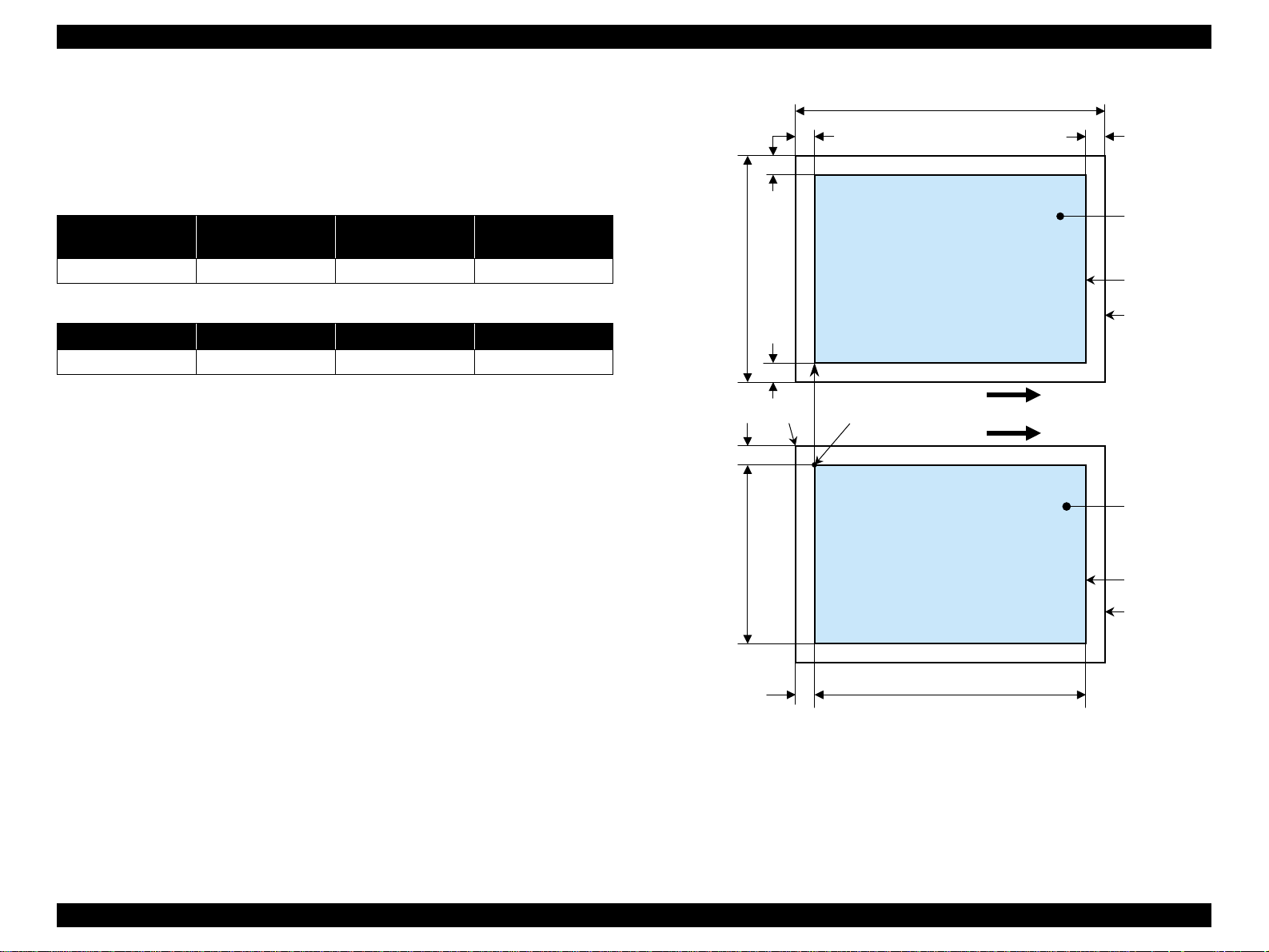
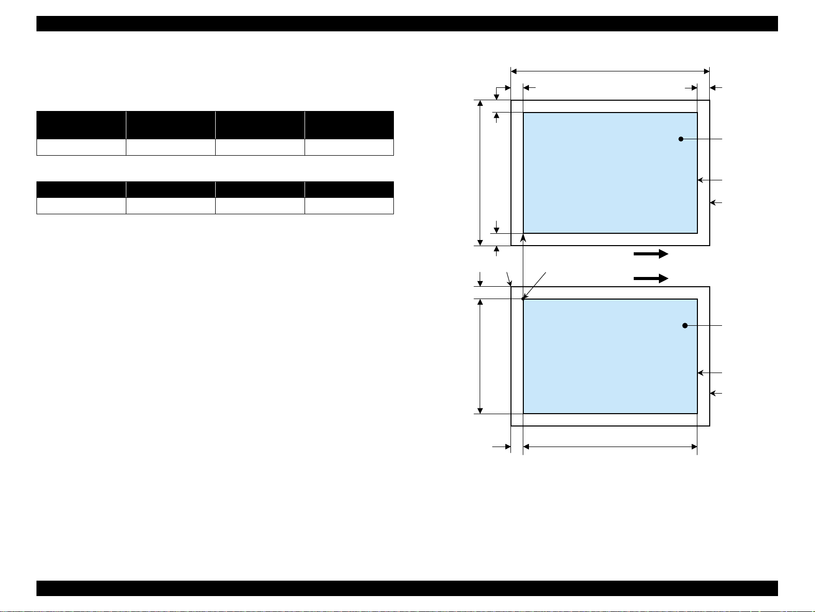
1.4.4 Relation between original and copy
1.4.4.1 Standard copy
The following table shows the relative positioning of the original and copy.
Table 1-26. Original (scanner)
RW
(readable width)
216 mm (8.5") 1.5 mm ± 1 mm 297 mm (11.7") 1.5 mm ± 1 mm
RM LM TM BM
3 mm (0.12") 3 mm (0.12") 3 mm (0.12") 3 mm (0.12")
Note : Refer to “1.2.1.4 Paper Support” (p.12) for paper width (PW) and paper length (PL).
(out-of-range left margin)
OLM
Table 1-27. Copy (printer)
RL
(readable length)
OTM
(out-of-range top margin)
OLM
RM
TopPW
LM
TopRW
*2*1
PL
Right side of copy
Print direction
Scan direction
BMTM
a
a
Copy
Print area
Copy paper
Original
(face down)
Scan area
Scan bed
Right side of original
OTM RL
Note *1: This indicates the top left corner of the original. Normally, this corner is aligned
with the scan bed's top right corner as the reference point.
*2 : This indicates the scan start position at the top left of the original, which
corresponds to the print start position at the top left of the copy. The bottom right
corner position of the copy is within the print area but varies accordi ng to the
enlarge/reduce setting.
Figure 1-10. Standard copy
PRODUCT DESCRIPTION Stand-alone Copy 27
EPSON Stylus CX3500/CX3600/CX3650/CX4500/CX4600 Revision A
1.4.4.2 BorderFree Copy
The following table shows the relative positioning of the original and copy.
Table 1-28. Original (scanner)
RW
(readable width)
216 mm (8.5") 1.5 mm ± 1 mm 297 mm (11.7") 1.5 mm ± 1 mm
RO LO TO BO
2.5 mm (0.09") 2.5 mm (0.09") 3 mm (0.12") 5 mm (0.2")
Note : Refer to “1.2.1.4 Paper Support” (p.12) for paper width (PW) and paper length (PL).
(out-of-range left margin)
OLM
Table 1-29. Copy (printer)
RL
(readable length)
OTM
(out-of-range top margin)
LO
OLM
TO
PL
Right side of copy
TopPW
a
Print direct ion
*2*1
Scan direction
a
TopRW
BO
Copy
Print area
Copy paper
Original
(face down)
Scan area
Scan bed
Right side of original
OTM RL
Note *1: This indicates the top left corner of the original. Normally, this corner is aligned
with the scan bed's top right corner as the reference point.
*2 : This indicates the scan start position at the top left of the original, which
corresponds to the print start position at the top left of the copy. The bottom right
corner of the print area varies according to th e scale setting in the print area.
Figure 1-11. BorderFree Copy
PRODUCT DESCRIPTION Stand-alone Copy 28
EPSON Stylus CX3500/CX3600/CX3650/CX4500/CX4600 Revision A
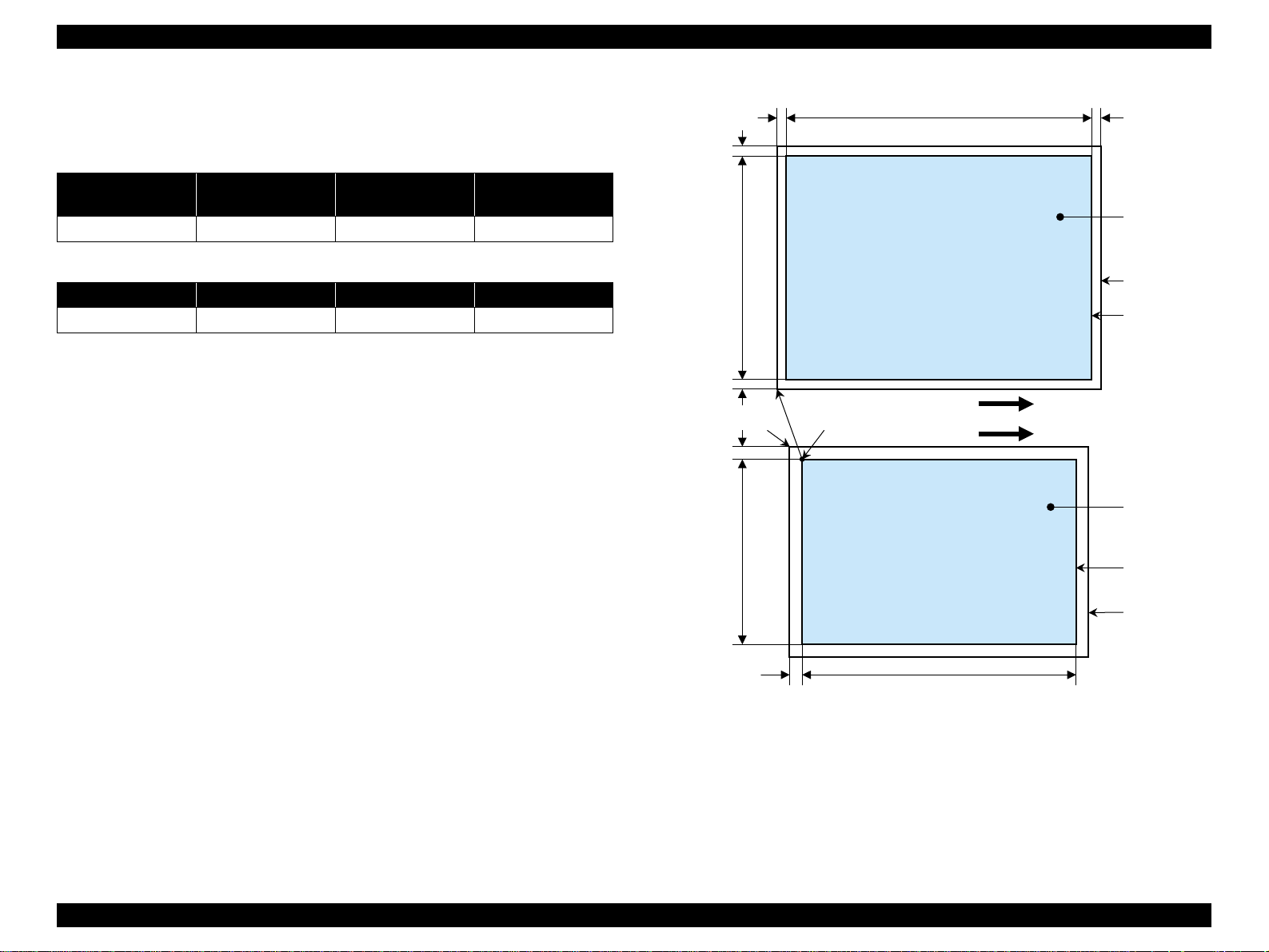
1.4.4.3 Small Margins copy
The following table shows the relative positioning of the original and copy.
Table 1-30. Original (scanner)
RW
(readable width)
216 mm (8.5") 1.5 mm ± 1 mm 297 mm (11.7") 1.5 mm ± 1 mm
RM LM TM BM
1.5 mm (0.06") 1.5 mm (0.06") 1.5 mm (0.06") 1.5 mm (0.06")
Note : Refer to “1.2.1.4 Paper Support” (p.12) for paper width (PW) and paper length (PL).
(out-of-range left margin)
OLM
Table 1-31. Copy (printer)
RL
(readable length)
OTM
(out-of-range top margin)
OLM
RM
TopPW
LM
TopRW
*2*1
PL
Right side of copy
Print direction
Scan direction
BMTM
a
a
Copy
Print area
Copy paper
Original
(face down)
Scan area
Scan bed
Right side of original
OTM RL
Note *1: This indicates the top left corner of the original. Normally, this corner is aligned
with the scan bed's top right corner as the reference point.
*2 : This indicates the scan start position at the top left of the original, which
corresponds to the print start position at the top left of the copy. The bottom right
corner position of the copy is within the print area but varies accordi ng to the
enlarge/reduce setting.
Figure 1-12. Small Margins copy
PRODUCT DESCRIPTION Stand-alone Copy 29

EPSON Stylus CX3500/CX3600/CX3650/CX4500/CX4600 Revision A
1.5 Memory Card Print (only for Stylus CX4500/CX4600)
1.5.1 Basic Specifications
1.5.1.1 File system
DCF Version 1.0 is the only file system that can be used with this unit's stand-alone
printing functions. Operation is not guaranteed when any other file system is used.
The file system used by the card reader function depends on the host's specifications.
For a detailed description of the DCF specifications, see the “Design Rule for Camera
File System Standard, DCF Version 1.0, JEIDA-49-2-1998”.
1.5.1.2 Media format
V Media must be formatted according to the DCF Version 1.0 standard.
V DOS FAT formats (FAT12, FAT16) and single partition (basic partition)
1.5.1.3 File formats
The file formats supported by this unit are described below.
V JPEG files (*.JPG)
These are photo data files that comply with the Exif Version 2.1 or Version 2.2
standard.
V Camera specification files (*.MRK)
These are definition files used when in camera specification mode. An
“AUTOPRINT.MRK” file whose full path name is no longer than 32 ch aracters is
valid.
Note, however, any file that is saved in the following directories or their sub-directories
cannot be included as files to be printed.
V Directories containing system properties or hidden properties
V Directories that contain any double-byte characters in the directory name
V “RECYCLED ” : Windows directory for deleted file s
V “PREVIEW” : Directories containing CASIO's DSC thumbnail images
V “SCENE” : Directories containing data for CASIO's DSC Best Shot
function
V “MSSONY” : Directories containing SONY's DSC e-mail image data, voice
memos, video files, or non-compressed images
1.5.1.4 Valid image size
The maximum image size handled by this unit is:
V Horizontal : 120 ≤ X ≤ 4600 (pixels)
V Vertical : 120 ≤ Y ≤ 4600 (pixels)
1.5.1.5 Maximum number of photo data files
This unit can handle up to 999 photo data files. If the amount of photo data to be
recorded exceeds the capacity of one memory card, this unit uses file sorting rules to
sort the photo data into v ali d photo data in f rames number ed f rom 1 to 999. Al though it
is possible to print photo data files with frame numbers over 999 that have been
specified for printing by camera specification files, the maximum number of frames
that can be specified is 999 frames.
If you insert a memory card t hat cont ains over 999 ph oto d ata fi les, only fi les up to 999
will be printed by the “Print All” or “Print index sheet” functions.
1.5.1.6 Thumbnail image data
This unit handles thumbnail image data in the DCF Version 1.0 format (Exif format,
160 x 120 pixels).
During this unit's Index sheet and memory card printing modes, the layout is 80
thumbnails per sheet (when using plain paper or special paper in high-speed print
mode).
1.5.1.7 File sorting
This unit stores all photo data files in the memory, using the photo data files' full-path
file names (for example, “\DCIM\100EPSON\EPSN0000.JPG”), and assigned photo
frame numbers. Since photo frame numbers are assigned based on this unit's own
proprietary file sorting rules, the assigned frame numbers do not necessarily match
those indicated by digital cameras.
PRODUCT DESCRIPTION Memory Card Print (only for Stylus CX4500/CX4600) 30
 Loading...