

Page 1

SERVICE MANUAL
Scanner • Printer • Copier
EPSON Stylus CX1500
ME100
SEOT04-006
Page 2

Notice
V All rights reserved. No p art of t his manual may be reprod uced, stored i n a ret rieval sy stem, or t ransmit ted in any form or by a ny means el ectroni c,
mechanical, photocopying, or otherwise, without the prior written permission of SEIKO EPSON CORPORATION.
V The contents of this manual are subject to change witho ut notice.
V All effort have been made to ensure the accuracy of the contents of this manual. However, should any errors be detected, SEIKO EPSON would
greatly appreciate being informed of them.
V The above not withstanding SEIKO EPSON CORPORATION can assume no responsibility for any errors in this manual or the consequences
thereof.
EPSON is a registered trademark of SEIKO EPSON CORPORATION.
General Notice: Other product names used herein are for identification purpose only and may be trademarks or registered trademarks of their
respective owners. EPSON disclaims any and all rights in those marks.
Copyright © 2004 SEIKO EPSON CORPORATION.
I&I CS/Quality Management & PL Department
Page 3

PRECAUTIONS
Precautionary notations throughout the text are categorized relative to 1) Personal injur y and 2) damage to equipment.
DANGER Signals a precaution which, if ignored, could result in serious or fatal personal injury. Great caution should be exercised in
performing procedures preceded by DANGER Headings.
WARNING Signals a precaution which, if ignored, could result in damage to equipment.
The precautionary measures itemized below should always be observed when performing repair/maintenance procedures.
DANGER
1. ALWAYS DISCO NNECT THE PRODUCT FROM THE POWER SOURCE AND PERIPHERAL DEVICES PERFORMING ANY
MAINTENANCE OR REPAIR PROCEDURES.
2. NO WORK SHOULD BE PERFORMED ON THE UNIT BY PERSONS UNFAMILIAR WITH BASIC SAFETY MEASURES AS DICTATED
FOR ALL ELECTRONICS TECHNICIANS IN THEIR LINE OF WORK.
3. WHEN PERFORMING TESTING AS DICTATED WITHIN THIS MANUAL, DO NOT CONNECT THE UNIT TO A POWER SOURCE UNTIL
INSTRUCTED TO DO SO. WHEN THE POWER SUPPLY CABLE MUST BE CONNECTED, USE EXTREME CAUTION IN WORKING ON
POWER SUPPLY AND OTHER ELECTRONIC COMPONENTS.
4. WHEN DISASSEMBLING OR ASSEMBLING A PRODUCT, MAKE SURE TO WEAR GLOVES TO AVOID INJURIER FROM METAL PARTS
WITH SHARP EDGES.
WARNING
1. REPAIRS ON EPSON PRODUCT SHOULD BE PERFORMED ONLY BY AN EPSON CERTIFIED REPAIR TECHNICIAN.
2. MAKE CERTAIN THAT THE SOURCE VOLTAGES IS THE SAME AS THE RATED VOLTAGE, LISTED ON THE SERIAL NUMBER/
RATING PLATE. IF THE EPSON PRODUCT HAS A PRIMARY AC RATING DIFFERENT FROM AVAILABLE POWER SOURCE, DO NOT
CONNECT IT TO THE POWER SOURCE.
3. ALWAYS VERIFY THAT THE EPSON PRODUCT HAS BEEN DISCONNECTED FROM THE POWER SOURCE BEFORE REMOVING OR
REPLACING PRINTED CIRCUIT BOARDS AND/OR INDIVIDUAL CHIPS.
4. IN ORDER TO PROTECT SENSITIVE MICROPROCESSORS AND CIRCUITRY, USE STATIC DISCHARGE EQUIPMENT, SUCH AS
ANTI-STATIC WRIST STRAPS, WHEN ACCESSING INTERNAL COMPONENTS.
5. REPLACE MALFUNCTIONING COMPONENTS ONLY WITH THOSE COMPONENTS BY THE MANUFACTURE; INTRODUCTION OF
SECOND-SOURCE ICs OR OTHER NONAPPROVED COMPONENTS MAY DAMAGE THE PRODUCT AND VOID ANY APPLICABLE
EPSON WARRANTY.
Page 4

About This Manual
This manual describes basic functions, theory of electrical and mechanical operations, maintenance and repair procedures of the printer. The instructions and
procedures included herein are intended for the experienced repair technicians, and attention should be given to the precautions on the preceding page.
Manual Configuration
This manual consists of six chapters and Appendix.
CHAPTER 1. PRODUCT DESCRIPTIONS
Provides a general overview and specifications of the
product.
CHAPTER 2. OPERATING PRINCIPLES
Describes the theory of electrical and mechanical
operations of the product.
CHAPTER 3. TROUBLESHOOTING
Describes the step-by-step procedures for the
troubleshooting.
CHAPTER 4. DISASSEMBLY / ASSEMBLY
Describes the step-by-step procedures fo r disassembling
and assembling the product.
CHAPTER 5. ADJUSTMENT
Provides Epson-approved methods for adjustment.
CHAPTER 6. MAINTENANCE
Provides preventive maintenance procedures and the
lists of Epson-approved lubricants and adhesives
required for servicing the product.
CHAPTER 7. APPENDIX
Provides the following additional information for
reference:
• Connector pin assignments
• Electric circuit boards components layout
• Electrical circuit boards schematics
• Exploded diagram & Parts List
Symbols Used in this Manual
Various symbols are used throughout this manual either to provide
additional information on a specific topic or to warn of possible danger
present during a procedure or an action. Be aware of all symbols when
they are used, and always read NOTE, CAUTION, or WARNING
messages.
ADJUSTMENT
REQUIRED
CAUTION
CHECK
PO INT
W ARNING
Indicates an operating or maintenance procedure, practice
or condition that, if not strictly observed, could result in
injury or loss of life.
Indicates an operating or maintenan ce pr ocedure, practi ce,
or condition that, if not strictly observed, could result in
damage to, or destruction of, equipment.
May indicate an operating or maintenance procedure,
practice or condition that is necessar y to accomplish a task
efficiently. It may also provid e additional information that is
related to a specific subject, or comment on the results
achieved through a previous action.
I.ndicates an operating or maintenance procedure, practice
or condition that, if not strictly obser ved, could result i n injury
or loss of life.
Indicates that a particular task must be carried out
according to a certain standard after disassembly and
before re-assembly, otherwise the quality of the
components in question may be adversely affected.
Page 5

Revision Status
Revision Issued Date Description
A 2004/9/1 First Release
NOTE: Since the Stylus CX1500/ME100 are OEM products, the contents of the specification differ from those of EPSON products.Therefore, the structure and
the contents of this service manual differ partly from usual manual.
Page 6

CONTENTS
Chapter 1 PRODUCT DESCRIPTION
1.1 Overview........................... ....... ...... ....... ...... ....... ...... ............................... 9
1.1.1 Features........................... ...... ....... ...... ............................................ 9
1.2 Specifications...................................................................................... 10
1.2.1 Printer specifications ..................................................................... 10
1.2.2 Scanner specifications ..................................... ....... ...... ....... ......... 17
1.2.3 Common........................................................................................ 18
1.3 Interface................................................................................................ 20
1.3.1 USB Interface................................................................................ 20
1.4 Stand-alone Copy................................................................................ 21
1.4.1 Basic Specifications ...................................................................... 21
1.4.2 Copy Speed................................................................................... 21
1.4.3 Copy Mode.................................................................................... 21
1.4.4 Relation between original and copy .............................................. 22
1.5 Control Panel....................................................................................... 23
1.5.1 Buttons.......................................................................................... 23
1.5.2 Indicators....................................................................................... 23
1.5.3 Operations..................................................................................... 25
1.5.4 Printer Condition and Panel Status ............................................... 27
1.5.5 Printer Initialization........................................................................ 28
Chapter 2 OPERATING PRINCIPLES
2.1 Overview............................................................................................... 30
2.1.1 Printer Mechanism ........................................................................ 30
2.1.2 Print Head ..................................................................................... 31
2.1.3 Carriage Mechanism..................................................................... 34
2.1.4 Paper Loading/Feeding Mechanism.............................................. 35
2.1.5 Ink System Mechanism ................................................................. 40
2.1.6 Ink Sequence .......................................................... ...... ....... ...... ... 43
2.2 Scanner Mechanism............................................................................ 45
2.2.1 Scanner Carriage Mechanism....................................................... 45
Chapter 3 TROUBLESHOOTING
3.1 Overview .............................................................................................. 48
3.2 Error Indications and Fault Occurrence Causes.............................. 48
3.3 Troubleshooting.................................................................................. 52
3.3.1 Superficial Phenomenon-Based Troubleshooting......................... 64
Chapter 4 DISASSEMBLY AND ASSEMBLY
4.1 Overview .............................................................................................. 73
4.1.1 Precautions................................................................................... 73
4.1.2 Tools ............................................................................................. 74
4.1.3 Work Completion Check ............................................................... 75
4.2 Caution regarding assembling/disassembling of the Printer
Mechanism, and how to ensure of quality on re-assembled product... 76
4.3 Disassembly ........................................................................................ 77
4.3.1 Document Cover ........................................................................... 78
4.3.2 Stacker.......................................................................................... 79
4.3.3 Panel Unit.................... ...... ....................................... ....... ...... ....... . 80
4.3.4 Panel Housing.......................... ...... ....... ....................................... . 81
4.3.5 Scanner Unit ................................................................................. 82
4.3.6 Housing Upper .............................................................................. 86
4.3.7 Main Board Unit ............................................................................ 87
4.3.8 Housing Middle ............................................................................. 89
4.3.9 ASF Unit................................... ..................................................... 90
4.3.10 Housing Lower (Outer)................................................................ 92
4.3.11 PS Board Unit ............................................................................. 93
4.3.12 Front Frame ................................................................................ 94
4.3.13 EJ Roller...................................................................................... 95
4.3.14 CR Motor..................................................................................... 96
Page 7

4.3.15 Paper Guide Upper ..................................................................... 98
4.3.16 Holder Shaft Unit....................................................................... 100
4.3.17 Print Head ................................................................................. 103
4.3.18 Waste Ink Pads......................................................................... 105
4.3.19 Housing Lower (Inner)............................................................... 106
4.3.20 PF Motor.................................................................................... 108
4.3.21 Ink System Unit......................................................................... 109
Chapter 5 ADJUSTMENT
5.1 Overview............................................................................................. 111
5.1.1 Required Adjustment................................................................... 111
5.1.2 Adjustment Program feature ....................................................... 112
5.1.3 Adjustment Except Adjustment Program..................................... 112
5.1.4 Timing Belt Tension Adjustment.................................................. 112
Chapter 6 MAINTENANCE
6.1 Overview............................................................................................. 116
6.1.1 Cleaning...................................................................................... 116
6.1.2 Service Maintenance................................................................... 116
6.1.3 Lubrication................................................................................... 118
Chapter 7 APPENDIX
7.1 Connector Summary......................................................................... 122
7.1.1 Major Component Unit ................................................................ 122
7.2 Exploded Diagram............................................................................. 123
7.3 Parts List............................................................................................ 130
7.4 Electrical Circuits.............................................................................. 131
Page 8

PRODUCT DESCRIPTION
CHAPTER
Page 9

EPSON Stylus CX1500/ME100 Revision A
1.1 Overview
The major features of EPSON color inkjet dot matrix printer EPSON Stylus CX1500/
ME100 are:
1.1.1 Features
V Printer functions
T Maximum print resolution : 1440 (H) x 720 (V) dpi
T ASF (Auto Sheet Feeder) holds up to 100 cut sheets (65g/m
V Scanner functions
T Maximum optical resolution : 600 x 1200dpi
T Scan gradations : 16bit/pixel/color
• Data output from AFE : 16bit/pixel/color
• Data output from Twain : 8bit/pixel/color or 1bit/pixel/color
V Stand-alone copy functions
T Paper size can be selected from 2 options.
2
)
Figure 1-1. Product’s external view
T Paper type can be selected from 2 options, plain paper or photo paper, which
also defines c opy quality.
T Enlarge/Reduce factor can be selected from 2 options, actual size (100%) or
“Fit to page”.
V Scan functions
This unit provides scan mode so that data can be scanned and transferred to a
connected computer or to e-mail via application software like the EPSON SMART
PANEL.
PRODUCT DESCRIPTION Overview 9
Page 10
EPSON Stylus CX1500/ME100 Revision A
1.2 Specifications
1.2.1 Printer specifications
This section covers specifications of the printer.
1.2.1.1 Physical Specification
V Weight : 5.1kg
V Dimension (Including rubber feet)
T Storage : 430mm (W) x 302mm (D) x 188.5mm (H)
1.2.1.2 Printing Specification
V Print Method
T On demand i nk jet
V Nozzle Configuration
T Monochrome 48 nozzles
T Color 15 nozzles x 3 (Cyan, Magenta, Yellow)
16.5mm
2.2578mm (32/360")
V Print Direction
T Bi-directional minimum distance printing (with logic seeking)
V Print Speed
Table 1-1. Print Speed
Paper
Type
Plain
Paper
Photo
Paper
Print Mode
Draft
360x120dpi
Default (Text)
360x360dpi
Photo RPM
720x720dpi
Default (Text & Image)
360x720dpi
Photo
720x720dpi
Photo RPM
1440x720dpi
e-Memo (A4)
J1 J6
Black Color
12ppm 5.3ppm — — —
5.3ppm 1.3ppm — — —
—————
— — — — 291sec
————630sec
— — — — 2010sec
V Control Code
T ESC/P Raster command
8x10
Bike
T EPSON Remote command
#B48
(1/120")
0.2117mm
#B1
Figure 1-2. Nozzle configuration
#Y15
#Y1
#C15
#C1
#M15
#M1
V Internal fonts
T Courier Regular font
T ASCII from 0x20 to 0x7E
V Input buffer size
T 128KByte for USB buffer
1.2.1.3 Paper Feed Specifications
V Paper feed method
Friction feed, using one ASF (Auto Sheet Feeder)
PRODUCT DESCRIPTION Specifications 10
Page 11
EPSON Stylus CX1500/ME100 Revision A
V Paper path
Top feed, front out
V Paper feed rates
T 110mm/sec (4.3inch/sec): 10.16mm feed
T 140mm/sec (5.5inch/sec): continuous feed
V CR interval
0.035mm (1/720inch) steps
1.2.1.4 Paper Support
V Cut sheets
Paper size
A4 210mm 297mm
A5 148mm 210mm
B5 182mm 257mm
Letter
Legal
Executive
Half Letter
User
defined
CAUTION
89-215.9mm 89-1117.6mm
T Poor quality paper may reduce print quality and cause paper
T It is necessary that there is no wrinkle, nap, tear, fold, so on in
T The curve of form must be 5mm or below.
T Use paper under normal conditions
Dimensions
Width Length
215.9mm
(8.5")
215.9mm
(8.5")
184.2mm
(7.25")
139.7mm
(5.5")
jams or other problems. If you encounter problems, switch to a
higher grade of paper.
the form.
• Temperature 15 to 25°C (59 to 77°F)
• Humidity 40 to 60% RH
Table 1-2. Cut sheets
Thickness Weight Paper type
279.4mm
(11")
355.6mm
(14")
266.7mm
(10.5")
215.9mm
(8.5")
0.08-0.11mm
64-90g/m
(17-24(lb))
2
Plain paper
Reclaimed paper
PRODUCT DESCRIPTION Specifications 11
Page 12
EPSON Stylus CX1500/ME100 Revision A
V Envelopes
Table 1-3. Envelopes
Paper size
No.10
DL 220 110
C6 162 114
220x132 220 132
Note "*": Check that the flap is on the long side and be sure to fold it down.
Dimensions
Width Length
241.3
(9.5")
104.8
(4.125")
Thickness Weight Paper type*
Bond paper
N/A
75-90g/m
(20-24(lb))
2
Air mail
PPC
CAUTION
T Use paper under normal conditions
• Temperature 15 to 25°C (59 to 77°F)
• Humidity 40 to 60% RH
T Poor quality paper may reduce print quality and cause paper
jams or other problems. If you encounter problems, switch to a
higher grade of paper.
T It is necessary that there is no wrinkle, nap, tear, fold, so on in
the form.
T Don’t use the adhesive envelopes.
T Don’t use sleeve insert envelopes and cellophane window
envelopes.
PRODUCT DESCRIPTION Specifications 12
Page 13
EPSON Stylus CX1500/ME100 Revision A
V Exclusive papers
Quality: EPSON Exclusive paper
Transparency printing is only available at normal temperature.
Table 1-4. Exclusive papers
Item Size
Bright White Ink Jet
Paper
Premium Bright White
Paper
Photo Quality Ink Jet
Paper
Matte Paper Heavy
weight
Photo Paper/
Glossy Photo Paper
Economy Photo Paper A4 210 297 0. 23 188
Photo Sticker 4/16 A6 105 148 0.19 N/A
Premium Glossy Phot o
Paper
A4 210 297 0.11 80
Letter 215.9 279.4 TBD TBD
Letter 215.9 279.4
Legal 215.9 355.6
A4 210 297
Index card 8"x10" 203.2 254
Index card 5"x8" 127 203.2
Index card A6 105 148
Letter 215.9 279.4
8"x10" 203.2 254
Letter 215.9 279.4
A4 210 297
10x15 101.6 152.4
4"x6"
No Perforations
4"x6"
Perforations
4"x6"
No Perforations
10x15 101.6 152.4
5"x7" 127 178
Width
(mm)
101.6 152.4
101.6 152.4
101.6 152.4
Length
(mm)
Thickness
(mm)
0.13 102
0.23 167A4 210 297
0.23 188
0.23 188
Weight
(g/m
Table 1-4. Exclusive papers
Item Size
Iron-on Cool Peal
Transfer Paper
2
)
Photo Quality Self
Adhesive Sheet
Double-Sided Matte
Paper
Ink Jet Transparencies
CAUTION
T Use paper under normal conditions.
• Temperature 15 to 25°C (59 to 77°F)
• Humidity 40 to 60% RH
Letter 215.9 279.4
A4 210 297
A4 210 297 0.19 167
Letter 215.9 279.4
A4 210 297
Letter 215.9 279.4
A4 210 297
Width
(mm)
Length
(mm)
Thickness
(mm)
0.18 124
0.25 178
0.13 N/A
Weight
2
(g/m
)
T Poor quality paper may reduce print quality and cause paper
jams or other problems. If you encounter problems, switch to a
higher grade of paper.
T It is necessary that there is no wrinkle, nap, tear, fold, so on in
the form.
T The curve of form must be 5mm or below.
PRODUCT DESCRIPTION Specifications 13
Page 14
EPSON Stylus CX1500/ME100 Revision A
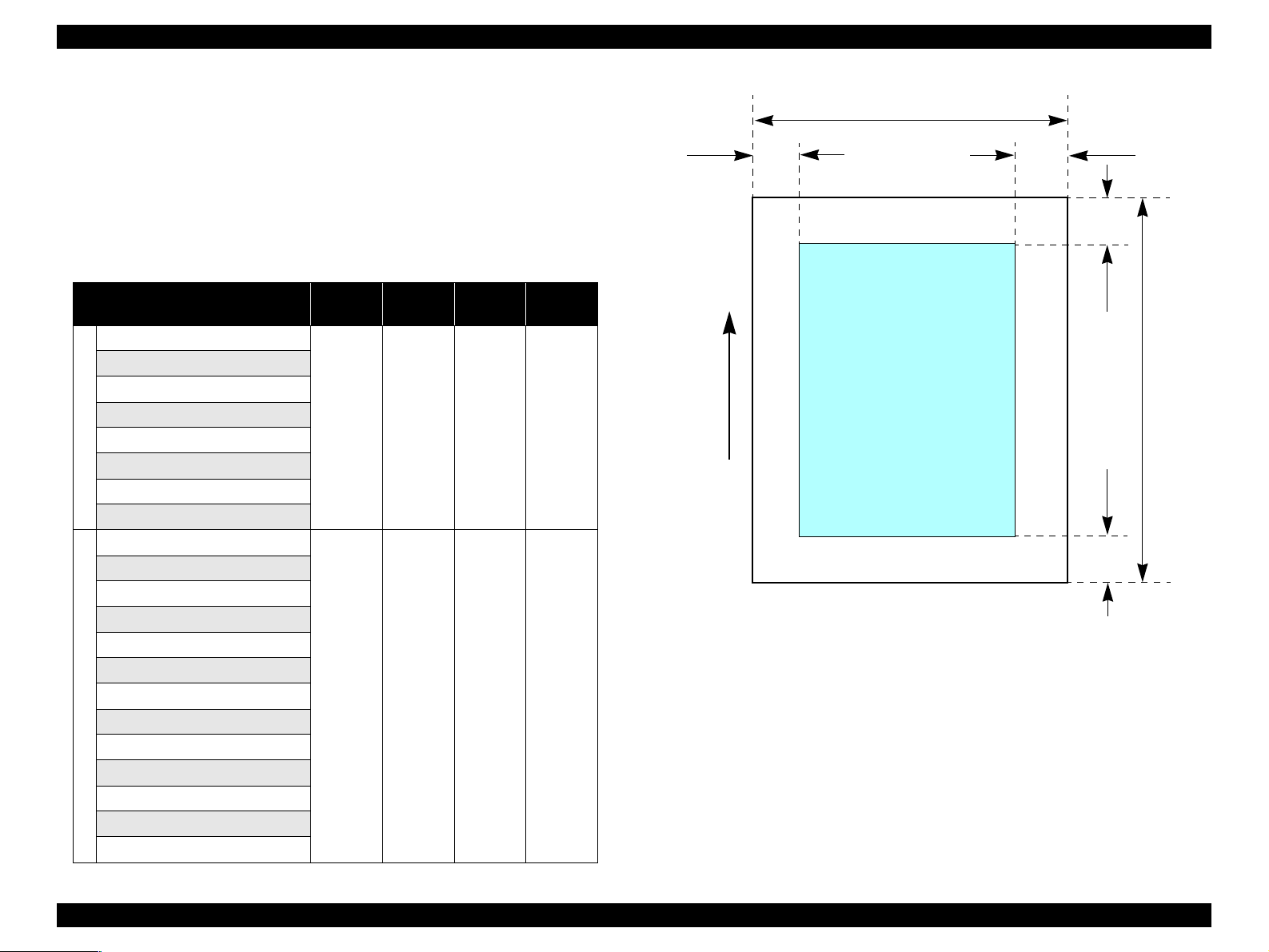
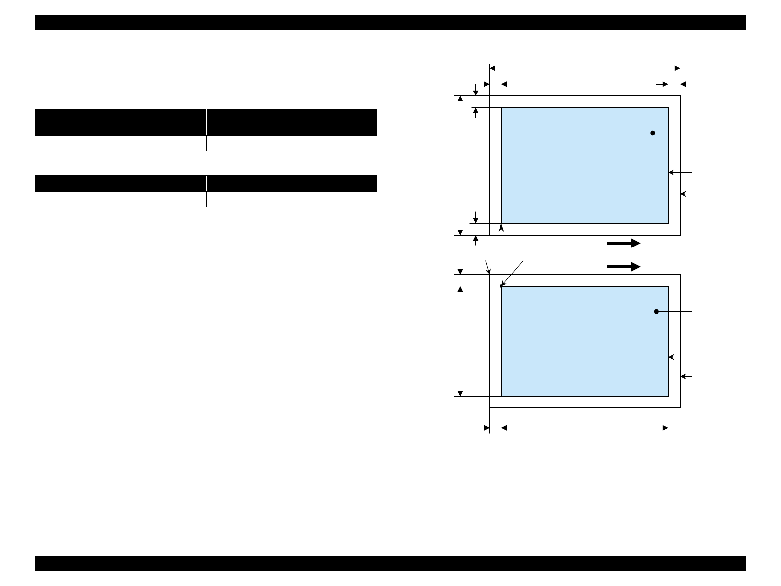
1.2.1.5 Printing Area
V Cut sheet (standard printing)
T Printable area
The print quality is guaranteed for the print area above the 12.5mm bottom
margin. For paper width (PW) and paper length (PL), refer to “1.2.1.4 Paper
Support” (p.11).
Refer to the following table. As for each margin area, refer to Figure 1-3
(p.14).
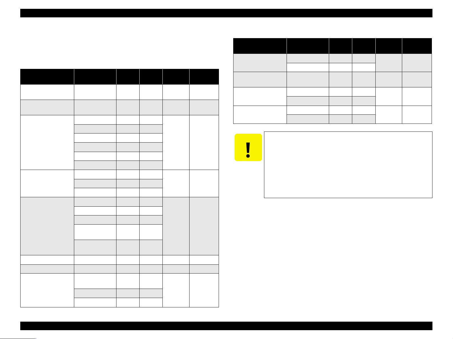
Table 1-5. Applicable paper/Printing area
Paper type
A4
A5
B5
Letter
Legal
Cut sheets
Executive
Half Letter
User defined
Bright White Ink Jet Paper
Premium Bright White Paper
Premium Ink Jet Plain Paper
Photo Quality Ink Jet Paper
Matte Paper Heavy weight
Photo Paper/Glossy Photo Paper
Economy Photo Paper
Photo Sticker
Exclusive pa pers
Premium Glossy Photo Paper
Iron-on Cool Peal Transfer Paper
Photo Quality Self Adhesive Shee t
Double-Sided Matt Paper
Ink Jet Tran s p ar encies
Left
margin
3mm
(0.12")
3mm
(0.12")
Right
margin
3mm
(0.12")
3mm
(0.12")
Top
margin
3mm
(0.12")
3mm
(0.12")
Bottom
margin
12.5mm
(0.49")
12.5mm
(0.49")
PW
LM
Printable area
Paper Feed Direction
Figure 1-3. Printable area Cut sheet (standard printing)
RM
TM
PL
BM
PRODUCT DESCRIPTION Specifications 14
Page 15

EPSON Stylus CX1500/ME100 Revision A
V Envelopes
T Printable area
For paper width (PW) and paper leng th (PL), refer to “1.2.1.4 Paper Support”
(p.11).
Refer to the following table. As for each margin area, refer to Figure 1-4
(p.15).
Table 1-6. Applicable paper/Printing area
Paper type Left Margin Right Margin Top Margin Bottom Margin
No.10
DL
3mm (0.12") 3mm (0. 12") 3mm (0.12") 12.5mm (0.49")
C6
220x132
PL
LM
RM
TM
Printable area
PW
Paper Feed Direction
BM
Figure 1-4. Printable area for envelopes
PRODUCT DESCRIPTION Specifications 15
Page 16

EPSON Stylus CX1500/ME100 Revision A
1.2.1.6 Ink Cartridge Specification
V Type : Exclusive cartridge
V Color
T Black ink cartridge : Black
T Color ink cartridge : Magenta, Cyan, Yellow
Table 1-7. Ink Cartridge
Color Stylus CX1500 ME100
Black T038 T057
Color T039 T058
V Print capacity
T Black ink cartridge : 330 pages / A4 (ISO/IEC10561 Letter Pattern at 360
dpi)
T Color ink cartridge : 180 pages /A4 (360 dpi, 5% duty each color)
V Ink life : 2 years from production date
V Storage temperature
Table 1-8. Storage Temperature
Situation Storage Temperat ur e Limit
o
Storage -20
Packing storage -30oC to 40oC
Transit -30
C to 40oC
o
C to 60oC
Within a month at 40°C
Within 120 hours at
60°C and within a mo nth
at 40°C
T Black ink cartridge
19.8mm
T Color ink cartridge
43.2mm
52.7mm
51.2mm (rib area)
38.5mm
18.3mm (rib area)
43.2mm
52.7mm
51.2mm (rib area)
V Dimension
T Black : 19.8mm (W) x 52.7mm (D) x 38.5mm (H)
42.9mm
38.5mm
T Color : 42.9mm (W) x 52.7mm (D) x 38.5mm (H)
CAUTION
T The ink cartridge cannot be refilled.
T The ink cartridge that passes the expiration date should not be
used.
T The ink in the ink cartridge freezes when leaving it in the
environment of -16°C or under. It takes 3 hours that the frozen
ink becomes usable when moving it from the environment of - 20
°C to the environment of 25°C.
41.4mm (rib area)
Figure 1-5. Ink cartridge
NOTE: Note that the Ink Cartridge
shape differs between Stylus
CX1500 and Stylus ME100.
PRODUCT DESCRIPTION Specifications 16
Page 17
EPSON Stylus CX1500/ME100 Revision A
1.2.2 Scanner specifications
This section covers specifications of the scanner.
1.2.2.1 Basic Specifications
V Product type : Flatbed color image scanner
V Scanning method : Scanning of fixed document with mobil e scan head
V Sensor : CIS
V Maximum scan area : 8.5" x 11.7" (216mm x 297mm)
V Document sizes : A4 or US letter
V Max. effective pixels : 5,100 x 7,020pixels (600dpi)
V Resolution
T Main scan : 600dpi
T Sub scan : 1200dpi with Micro Step
V Scanning resolution : 50 to 2400dpi (selectable in 1-dpi steps), 7200dpi,
9600dpi
V Gradations (pixel depth) : Each color pixel has 16-bit input and either 1-bit or 8-
bit output.
V Scanning speed : 600dpi
T Color : Approx. 15msec/line
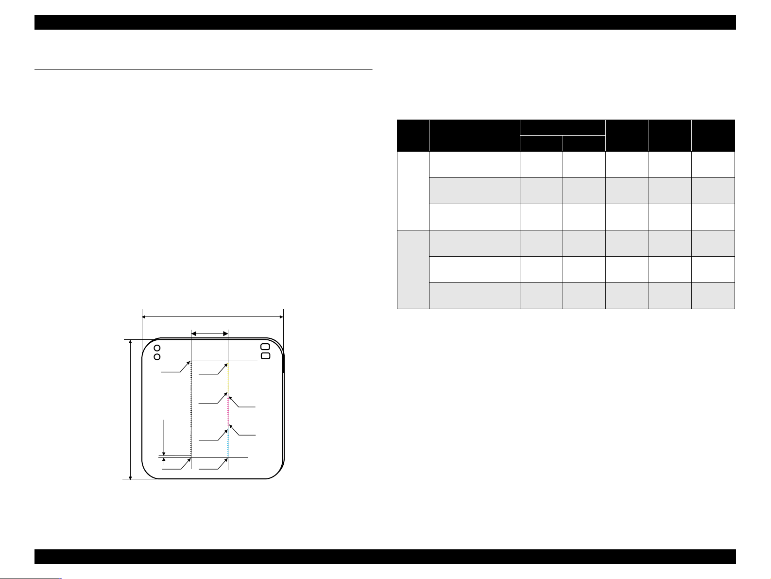
1.2.2.3 Image scanning area
Table 1-9. Image scanning area
RW
(readable width)
216mm (8.5") 2.5mm ± 1mm 297mm (11.7") 2.5mm ± 1mm
OLM
(out-of-range left margin)
Original's top left alignment position
First pixel
OLM
Scan direction
RL
(readable length)
(out-of-range top margin)
a
RW
RLOTM
OTM
Original
(face down)
Scan bed
Scan area
T Monochrome : Approx. 5msec/line
V Light source : RGB Three Color LED
Figure 1-6. Image scanning area
1.2.2.2 Detailed Specifications
V Control commands : ESC/I D7
V Gamma correction : Two user-defined levels
PRODUCT DESCRIPTION Specifications 17
Page 18
EPSON Stylus CX1500/ME100 Revision A
1.2.3 Common
1.2.3.1 Electric Specification
V Power input
Table 1-10. Power input
100-120V model 220-240V model
Rated power supply voltage (ACV) 100 ~ 120 220 ~ 240
Input voltage range (ACV) 90 ~ 132 198 ~ 264
Rated current (A) 0.41 (Typ), 0.6 (Max) 0.24 ( Typ ), 0.3 5 (M ax)
Rated frequency (Hz) 50 ~ 60
Input frequency range (Hz) 47 ~ 63 for rated input frequency 50 ~ 60
Standby 4.2 (Typ), 5 (Max) 4.6 (Typ), 5 (Max)
Idle 7.5 (Typ), 8 (Max) 8 (Typ), 8.5 (Max)
Scanning 11.5 (Typ), 12 (Max) 12.0 (Typ), 12.5 (Max)
Power
consumption (W)
Printing
Copying
• 14.5 (Text Black Plain
Paper) (Typ)
• 27 (Draft Color Plain
Paper) (Max)
• 17.0 (Normal BK Mode)
(Typ)
• 32.5 (Draft BK Mode)
(Max)
• 15.2 (Text Black Plain
Paper) (Typ)
• 27.0 (Draft Color Plain
Paper) (Max)
• 17.5 (Normal BK Mode)
(Typ)
• 32.5 (Draft BK Mode)
(Max)
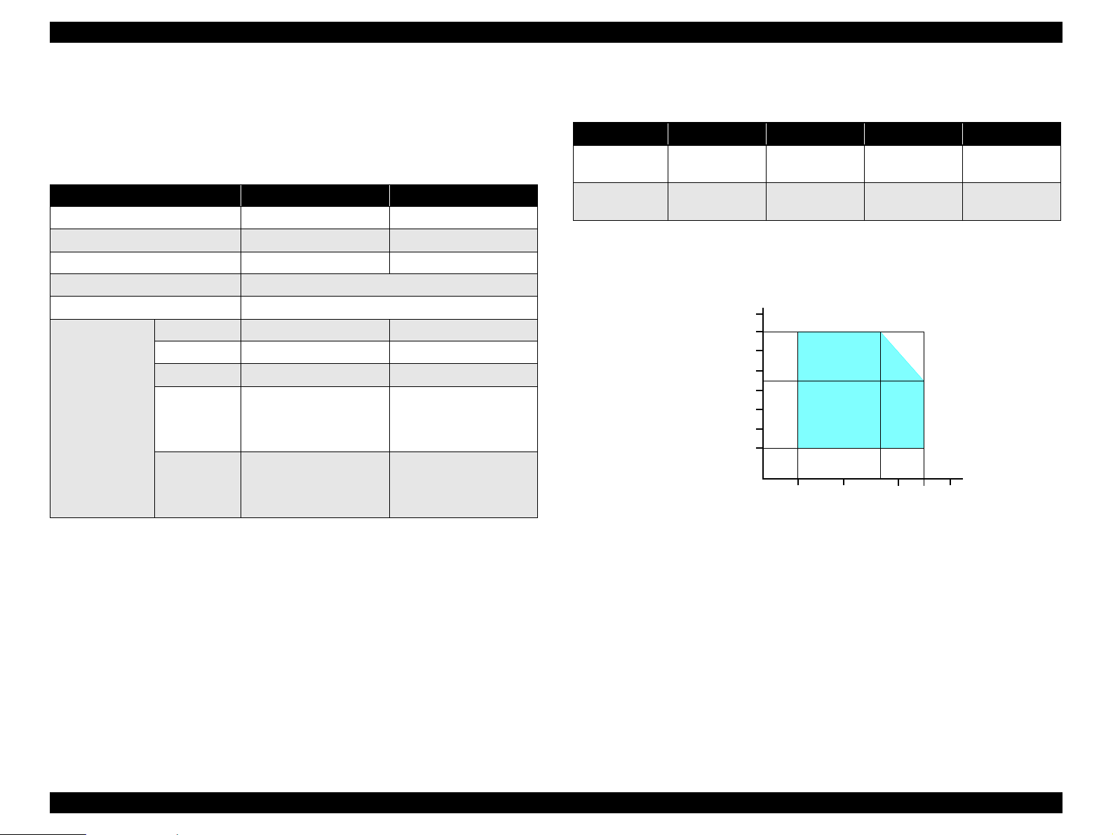
1.2.3.2 Environmental Performance
Table 1-11. Environmental Performance
Condition Temperature Humidity *
3
Operating 10 ~ 35°C *
Not operating *
Note *1: When packed for shipping
*2: No cond ensation
*3 : Under the following conditions
1
-20 ~ 60°C 5 ~ 85%
Humidity (%)
90
80
70
60
50
40
30
20
20 ~ 80% *
10
Temperature (°C)
2
3
20
Impact Vibration
1G,
-3
1 x 10
seconds
2G,
-3
2 x 10
seconds
27
35 40
30
1.5G
1.5G
Note : This product complies with the “Energy Star” standards.
Figure 1-7. Temperature/Humidity range
V Insulation resistance
10MΩ minimum (tested betw een AC line and chassis, test voltage: DC500V)
V Dielectric strength
AC1500Vrms for one minute
1.2.3.3 Durability
V Total print life : 20,000 pages (A4), or 5 years (whichever comes first)
V Print Head Life : 4 billion shots (per nozzle) or 5 years (whichever
comes first)
V Scanner head : MCBF (18,000 cycles)
PRODUCT DESCRIPTION Specifications 18
Page 19

EPSON Stylus CX1500/ME100 Revision A
1.2.3.4 Safety Standards/EMC/CE Marking
T CSA108.8 Class B
T UL CSA C22.2 No.60950
T UL60950 / CSA C22.2No.60950
T CCC
T IEC60950
T Korea EMC
T Korea
T Singapore safety standard/SS Mark
T TUV-S Argentina safety
T FCC15B Class B
T CE
• EN55022 (CISPR Pub22) Class B
• EN61000-3-2
• EN61000-3-3
• EN55024
T EPSR
T C-TICK-ASINZS 3548 Class B
T NOM
T CNS13438 Class B
1.2.3.5 Acoustic Noise
V Noise level
48.5dB (approx.) (according to ISO7779 when for copying)
PRODUCT DESCRIPTION Specifications 19
Page 20
EPSON Stylus CX1500/ME100 Revision A
1.3 Interface
The EPSON Stylus CX1500/ME100 provides the following interface.
1.3.1 USB Interface
V Standards
T “Universal Serial Bus Specifications Revision 2.0”
T “Universal Serial Bus Device Class Definition for Printing Devices Version
1.1” (printer unit)
T “Universal Serial Bus Mass Storage Class Bulk-Only Transport Revision 1.0”
(storage unit)
V Transfer rate : 12Mbps (Full Speed Device)
V Data format : NRZI
V Compatible connector : USB Series B
V Recommended cable length : 2 [m] or less
V Device ID
.
Model
Name
ME100
Device ID
@EJL[SP]ID[CR][LF];
MFG:EPSON;
CMD:ESCPL2,BDC;
MDL:ME[SP]100;
CLS:PRINTER;
DES:EPSON[SP]ME[SP]100;
[FF]
Model
Name
Stylus
CX1500
Table 1-12. Device ID
Device ID
@EJL[SP]ID[CR][LF];
MFG:EPSON;
CMD:ESCPL2,BDC;
MDL:Stylus[SP]CX1500;
CLS:PRINTER;
DES:EPSON[SP]Stylus[SP]CX1500;
[FF]
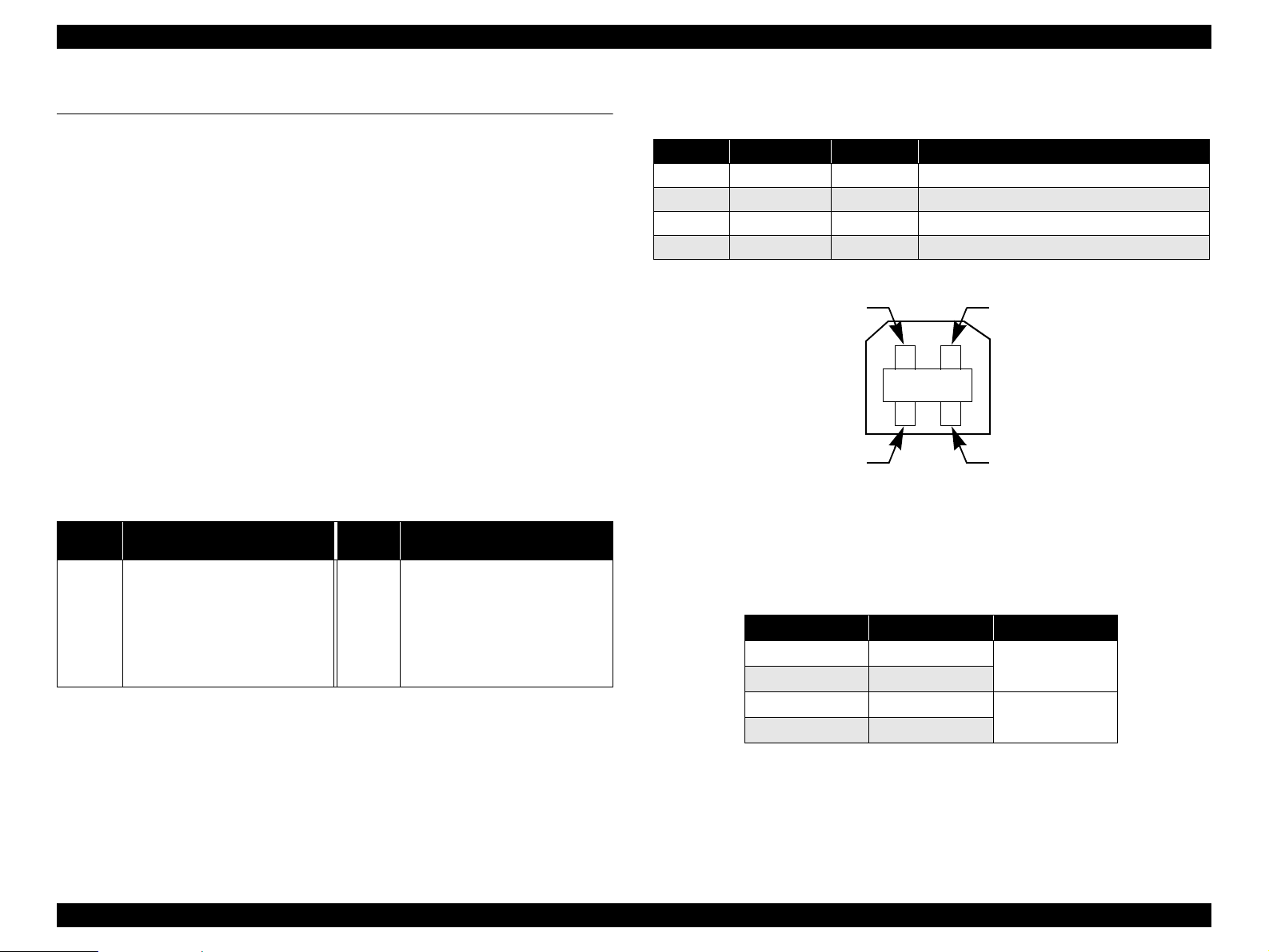
V Connector signal layout
Table 1-13. Connector pin assignment and signals
Pin No. Signal name I/O Function des c ription
1 VCC - Cable power. Max. power consumption is 2mA.
2 -Data Bi-D Data
3 +Data Bi-D Data, pull up to +3.3V via 1. 5K ohm resistor.
4 Ground - Cable ground
Pin #2
Pin #3
Pin #1
Pin #4
Figure 1-8. USB pin Assignment
V Product ID: 0x081
V Endpoint attribute
Table 1-14. Endpoint attrib ute
Endpoint Address Endpoint Type Linked Interface
0x01 Bulk In
0x02 Bu lk Out
0x03 Bulk In
0x04 Bu lk Out
Scanner
Printer
PRODUCT DESCRIPTION Interface 20
Page 21

EPSON Stylus CX1500/ME100 Revision A
1.4 Stand-alone Copy
1.4.1 Basic Specifications
1.4.1.1 Supported paper sizes, types and qualities
Table 1-15. Supported paper sizes, types and qualities
Paper type
Quality *
Paper name Panel Indication
Plain Paper Plain Paper Plain Paper A4/Letter
Premium Glossy Photo Paper Photo Paper Photo Paper 10x15/4"x6"
Note : The quality of draft copy is not affected by “Paper type” selection.
Note *1: Connected with Paper type.
1.4.1.2 Zoom function
The zoom function provides enlarged or reduced copies of originals. The either of the
following can be selected from the operation panel.
V Actual (The state which “Fit to page” is not selected. It is the power-on default.)
The zoom factor is set to 100%.
V Fit to page
This function detects the image size of the original and automatically sets the
zoom factor of the copy according to the copy paper’s printable area.
1.4.1.3 Number of copies setting
This function sets the number of copies. The setting range is 1 to 3.
1.4.1.4 Maximum copy size
V 216 x 297mm
1.4.1.5 Copy layout
1
Paper size
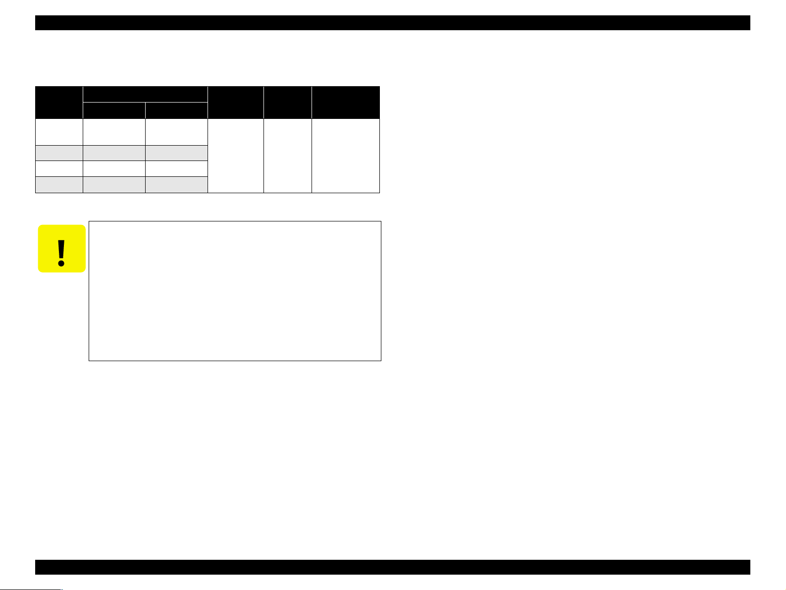
1.4.2 Copy Speed
Table 1-16. Copy Speed
e-memo Pattern
(A4, Epson
Matter Paper)
8x10 Bike on
Epson PGPP
Mode
Draft
Normal
Paper
Type
Plain
Paper
Plain
Paper
Black/
Color
Black 10cpm – Copy on Epson
Color 4cpm –
Black 4cp m – Copy on Epson
Color 1cpm –
Photo PGPP Black/Color – 400sec
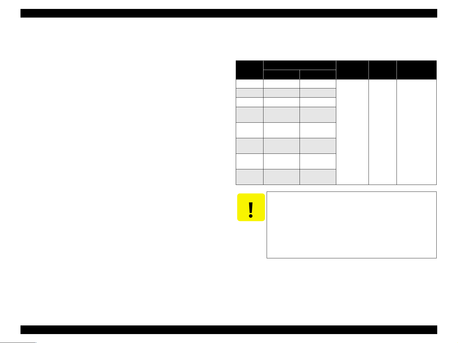
1.4.3 Copy Mode
Table 1-17. Copy Mode
Mode
Draft
Black
Draft
Color
Normal
Black
Normal
Color
Photo
Black
Photo
Color
Paper
Type
Plain
Paper
Plain
Paper
Plain
Paper
Plain
Paper
PGPP 600x600 RGB 720x720 Off Both Off VD 2x6
PGPP 600x600 RGB 720x720 Off Both Off VD 2x6
Scan
Input
Resolution
600x150 Gray 360x120 On Black On ND3 1x1
600x150 RGB 360x120 On Both On ND3 1x1
600x300 Gray 480x240 On Black On MS1 1x2
600x300 RGB 360x360 On Both On MS2 1x3
Scan
Input
Color
Print
Output
Resolution
High
Speed
Ink
Cartridge
Usage
A4 size premium
plain paper
A4 size premium
plain paper
Copy on Epson
4"x6" PGPP
Back-
ground
Removal
Dot
Size
Note
Interlace
Method
The following copy layout is pr ovided accordin g to “Med ia Select (Paper typ e & Paper
size)” and zoom selections.
V Standard copy
Provided for ordinary use with 3mm copy margin from every side.
PRODUCT DESCRIPTION Stand-alone Copy 21
Page 22
EPSON Stylus CX1500/ME100 Revision A
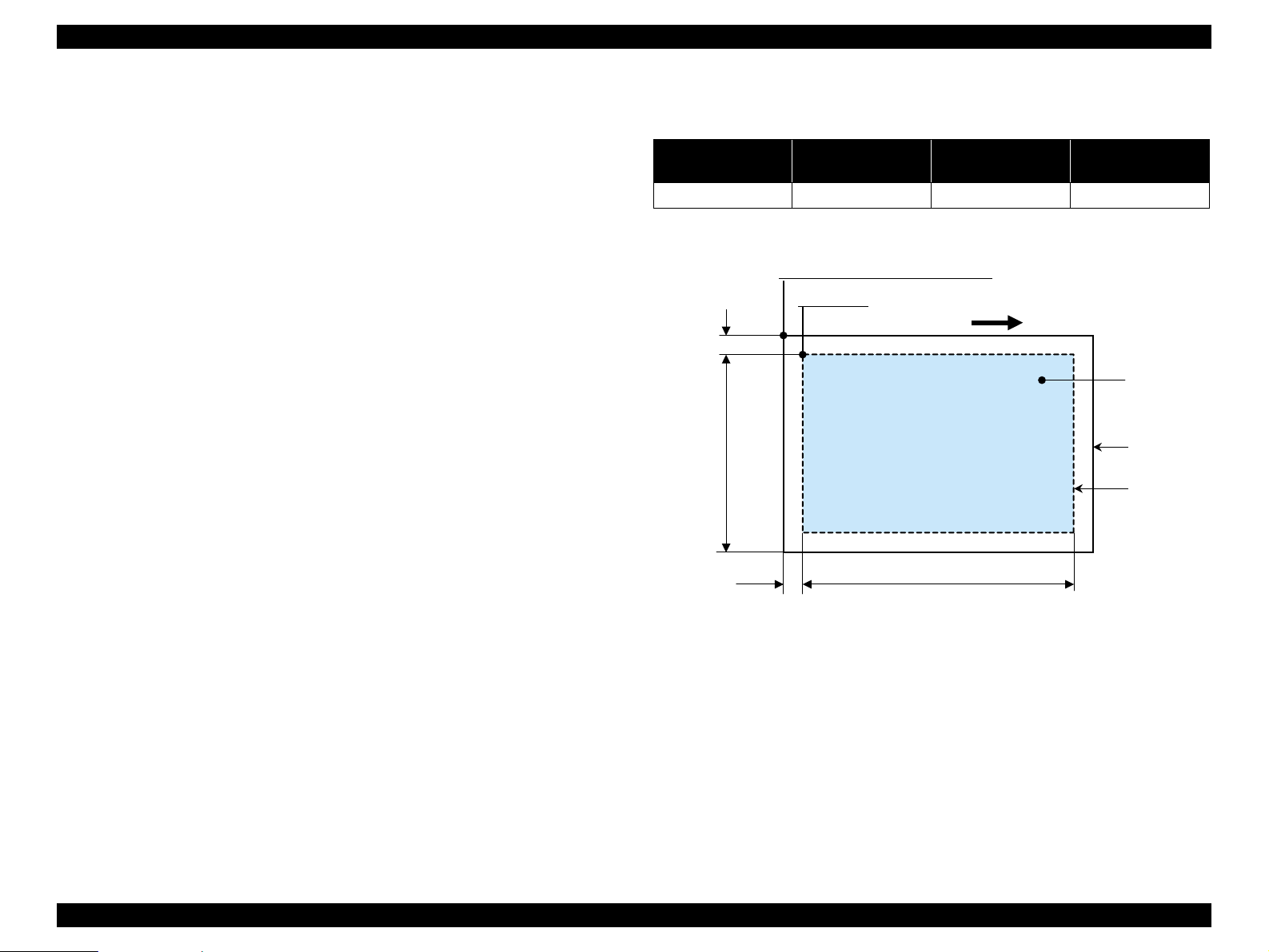
1.4.4 Relation between original and copy
The following table shows the relative positioning of the original and copy.
Table 1-18. Original (scanner)
RW
(readable width)
216mm (8.5") 2.5mm ± 1mm 297mm (11.7") 2.5mm ± 1mm
RM LM TM BM
3mm (0.12") 3mm (0.12") 3mm (0.12") 3mm (0.12")
Note : Refer to “1.2.1.4 Paper Support” (p.11) for paper width (PW) and paper length (PL).
(out-of-range left margin)
OLM
Table 1-19. Copy (printer)
RL
(readable length)
OTM
(out-of-range top margin)
OLM
RM
TopPW
LM
TopRW
*2*1
PL
Right side of copy
Print direction
Scan direction
BMTM
a
a
Copy
Print area
Copy paper
Original
(face down)
Scan area
Scan bed
Right side of original
OTM RL
Note *1: This indicates the top left corner of the original. Normally, this corner is aligned
with the scan bed’s top right corner as the reference point.
*2 : This indicates the scan start position at the top left of the original, which
corresponds to the print start position at the top left of the copy. The bottom right
corner position of the copy is within the print area but varies accordi ng to the
enlarge/reduce setting.
Figure 1-9. Standard copy
PRODUCT DESCRIPTION Stand-alone Copy 22
Page 23
EPSON Stylus CX1500/ME100 Revision A
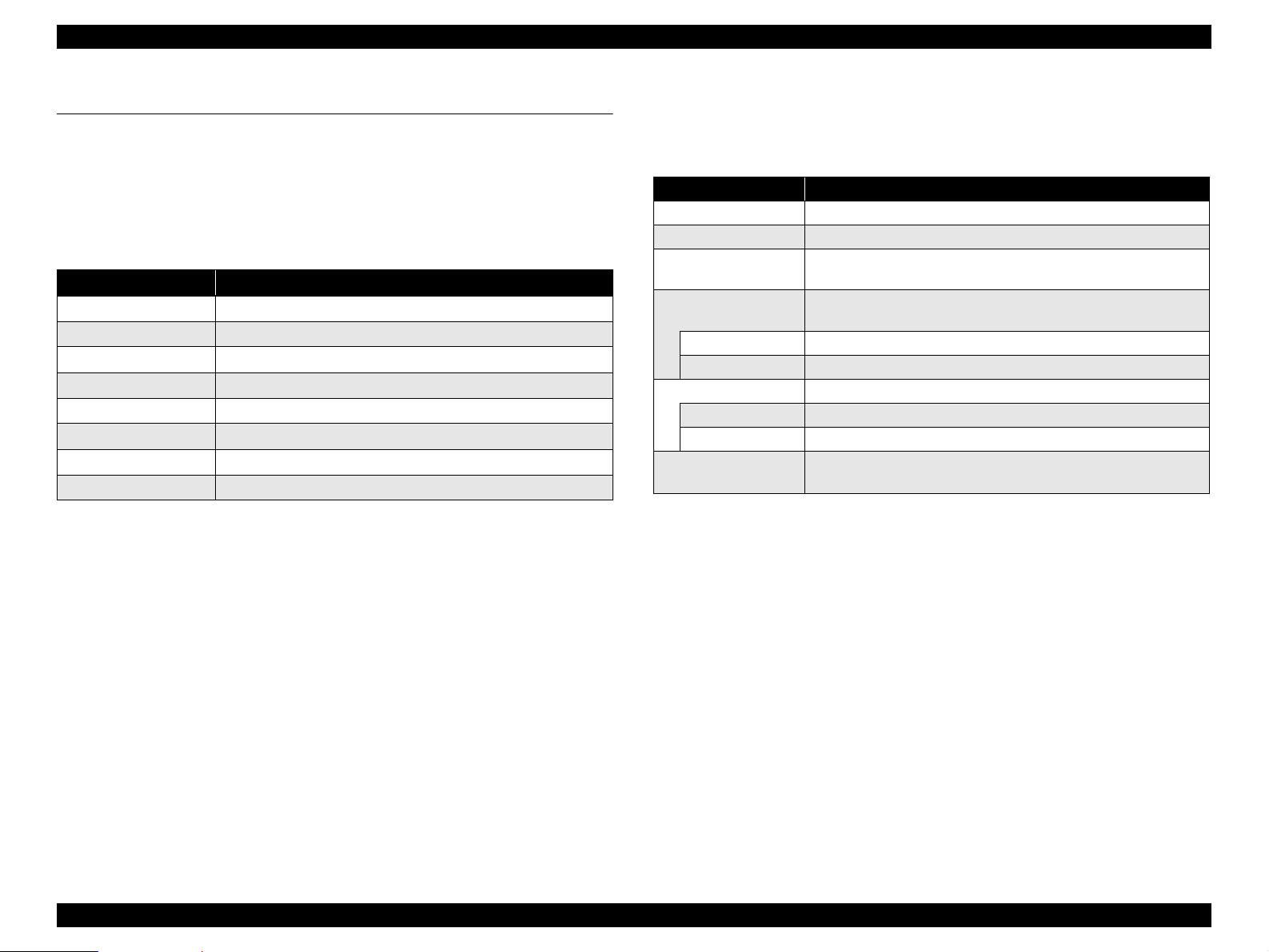
1.5 Control Panel
1.5.1 Buttons
The control panel contains following 8 buttons, which are used to set and execute
various ope rations.
All of them are non-lock type buttons.
Table 1-20. Buttons
Button Function
Power Button Execute turning on/of f this unit.
Ink Mainte nance Button Execute exchanging ink cartridges or head cleaning.
Number of copies Button Sets number of copies.
Media Select Button Select paper type.
Fit to Page Button Setting On/Off of Fit-to-Page
B&W Start Button *
Color Start Button Start color copy.
Stop Button Stop job of copying or printing or sometimes work as shift button.
Note *1: B&W means “Black and White”.
Refer to “1.5.3.1 Normal Operation” (p.25) for details about each button.
1
Start monochrome copy.
1.5.2 Indicators
The control panel contains following 8 LEDs, which are used to indicate various status.
Table 1-21. Indicators
LED Function
Power LED [Green] Light at stand-by. Blink while some operation is proceeding.
Paper Error LED [Red] Light or blink while some error or warning is occurring.
Ink Error LED [Red]
Number of Copies LED
2, 3
2nd [Green] Number of Copy = 2
3rd [Green] Number of Copy = 3
Paper Type LED 1, 2 Light one of them showing which paper si ze below is selected.
1st [Green] Plain Paper (A4/Letter)
nd
[Green] Photo Paper (10x15/4"x6")
2
Fit to Page LED
[Green]
Light when some ink is out. Blink when some ink is near empty or
in the ink cartridge exchanging procedure.
Indicate num b er of co pies.
Light when “Fit to Page” function is effective in copy mode.
PRODUCT DESCRIPTION Control Panel 23
Page 24
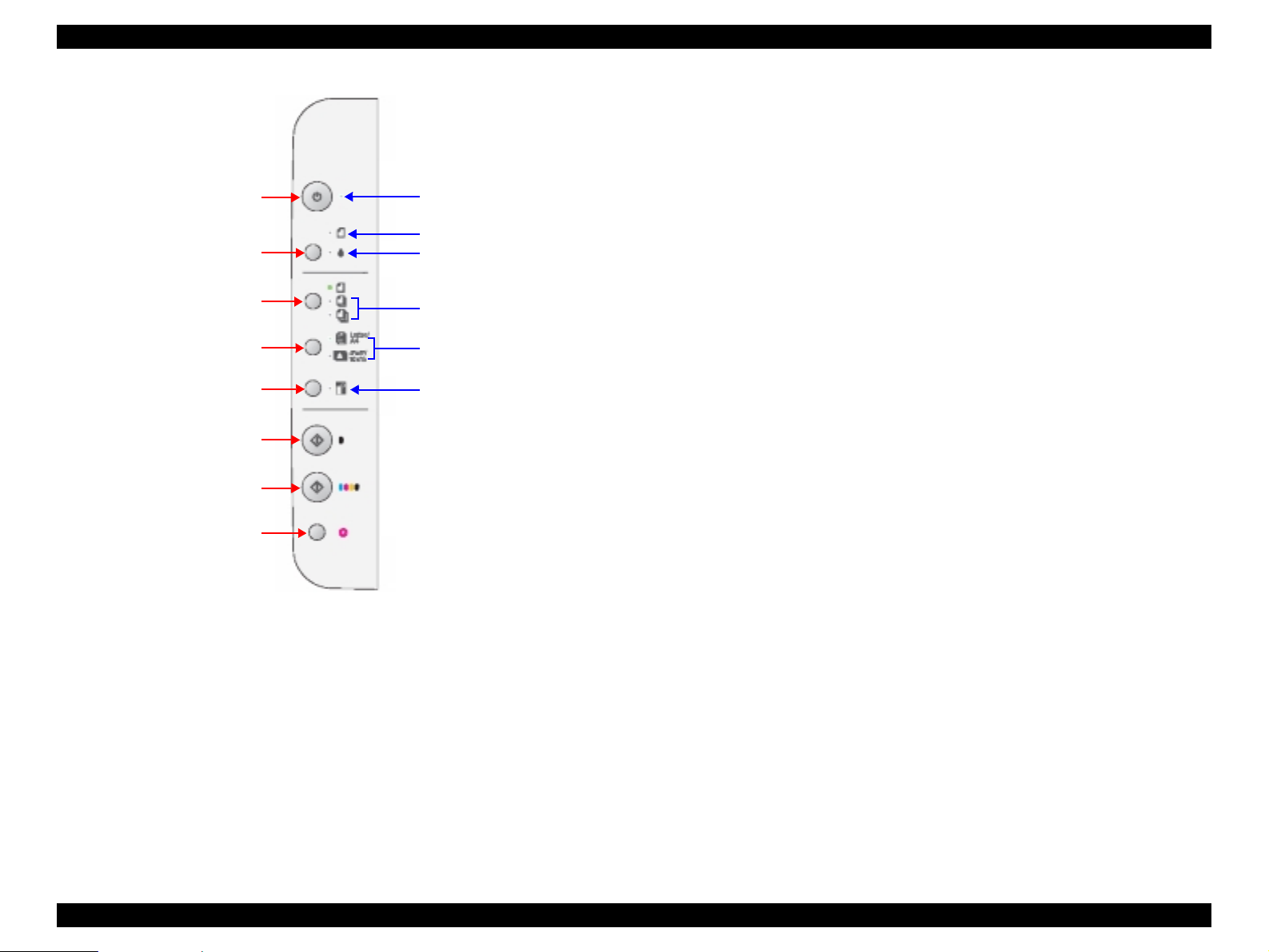
EPSON Stylus CX1500/ME100 Revision A
Power Button
Ink Maintenance Button
Number of copies Button
Media Select Button
Fit to Page Button
B&W Start
Button
Color Start
Button
Stop Button
Power LED
Paper Error LED
Ink Error LED
Number of Copies LED 2, 3
Paper Type LED 1, 2
Fit to Page LED
Figure 1-10. Control panel
PRODUCT DESCRIPTION Control Panel 24
Page 25

EPSON Stylus CX1500/ME100 Revision A
1.5.3 Operations
1.5.3.1 Normal Operation
Table 1-22. Normal Oper ation
Button Condition Function
V Enter Power On State
Power
Button
Ink
maintenance
Button
Number of
Copy
1
Button*
Media
Select
1
Button*
Fit to page
2
Button*
At Standby
At other state
except
Standby
•Idle state
•Ink Low
•Ink Out
Paper Error Push to recover Paper Error
Power On
Setting
Number of
Copy
Error release Reset to “1”.
Power On
Setting
Media Type Alternate paper type of “Plain Pa pe r” and “PGPP”.
Factory
Setting
Fit-to-Page Alternate Fit-to-Page of On and Off.
V Power LED blink until enter Idle state.
V At Idle state, Power LED keeps On.
V Enter Power Off State
V Power LED blink until enter Standby state.
V At Standby state, all LEDs keep Off.
V Press less than 3 sec
1. If no Paper in Printer, load paper (Idle state, Ink Low)
2. If Paper in Printer, eject paper (Idle state, Ink Low)
T Exchange Ink Cartridge (Ink Out)
V Press between 3 to 6 sec
T Head Cleaning (Idle state)
T Exchange Ink Cartridge (Ink Low, Ink Out)
V Press over 6 se c
T Force to excha nge Ink Cartridge
Number of Copy = 1
V Add 1 and the number becomes 2 to 3.
V Reset to “1”.
Plan paper
OFF
Table 1-22. Normal Operation
Button Condition Function
V B&W copy start.
1. Paper size & type, Fit-to-Page settings are stored.
2. Based on the setting, do B&W copy.
B&W copy
In Idle state
start Button
In Error state Continue processing
Color copy
In Idle state
start Button
In Error state Continue processing
In Copying
Stop
Button*
state
3
In Error state
Note *1: Only valid in idle state and paper out error.
*2: Only valid in idle state.
*3: Not valid for Scanning, Printing, Head Cleaning, Ink Cartridge Exchange and Power
On/Off.
3. When Copy finished, restore Number of copies, Paper
size & type, Fit-to-Page setting to Panel. Number of
Copy Reset to “1”.
4. If paper out error is happened in 2nd or 3rd cop ies, stop
the copy operation, cancel the paper out error
automatically and enter Idle state.
V Color copy start.
1. Paper size & type, Fit-to-Page settings are stored.
2. Based on the setting, do B&W copy.
3. When Copy finished, restore Number of copies, Paper
size & type, Fit-to-Page setting to Panel. Number of
Copy Reset to “1”.
4. If paper out error is happened in 2nd or 3rd cop ies, stop
the copy operation, cancel the paper out error
automatically and enter Idle state.
1. Stop and cancel the job of copy.
2. If there is a paper, or there might have a paper, discharge
the paper.
3. Restore the Number of copies, Paper size & type, Fit-toPage setting to Panel. Number of Copy Reset to “1”.
1. Cancel current
2. Number of Copy Reset to “1”.
PRODUCT DESCRIPTION Control Panel 25
Page 26

EPSON Stylus CX1500/ME100 Revision A
1.5.3.2 Maintenance Operation
Nozzle check pattern print
V Condition
Press Ink maintenance button with Power button to turn on this unit
V Function
T Nozzle check pattern is printed standalone.
T Remaining ink quantities of each color are printed.
T Enter Idle mode after printing completed.
The example of nozzle check pattern is below.
<Black>
Firmware
version
Waste ink
counter
Figure 1-11. Nozzle check pattern
<Cyan>
<Magenta>
1.5.3.3 Service Operation
The ink overflow counter can be reset using the steps below.
1. Number of copies button with Power button-ON
T Enter to maintenance setting mode.
T Make all LED turn on for 1 second.
T The contents of initialization when each button is pressed are shown in the
Step 2.
T Return to the mode if the button other an in the Step 2 is pressed.
2. B&W start button is pressed more than 3 seconds and less than 10 seconds.
T Reset ink overflow counter while in maintenance mode.
<Yellow>
Paper size exchange mode
V Condition
Press B&W (Color) Start button with Media Select button at the same time
V Function
T Paper Size selection is change to A4/4"x6" (Letter/4"x6") mode.
T Confirm the setting by flushing all LEDs once.
NOTE: Only valid in idle state.
PRODUCT DESCRIPTION Control Panel 26
Page 27
EPSON Stylus CX1500/ME100 Revision A
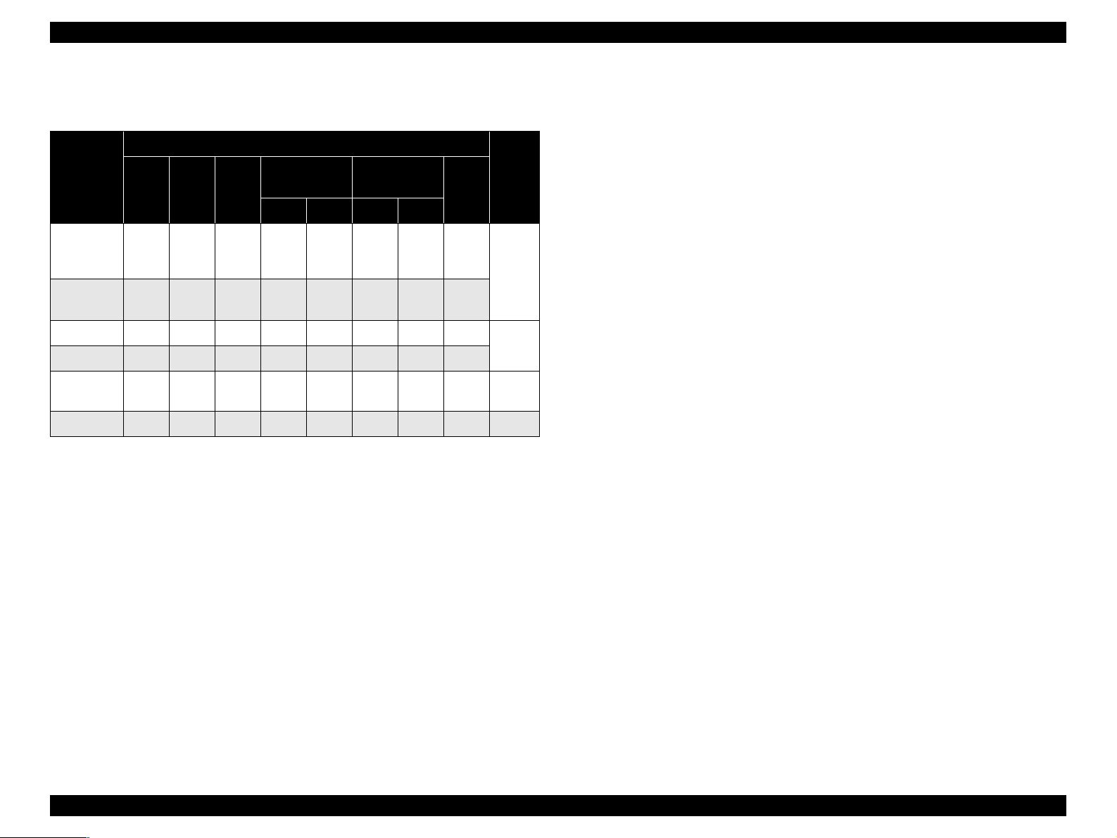
1.5.4 Printer Condition and Panel Status
Table 1-23. Printer Condition and Panel Status
Indicators
Printer
status
Ink out or
No Ink
cartridge
Incorrect
I/C
Paper out —On——————
Paper jam — On — — — — — —
Maintenance
request
Fatal error On On On On On On On On 1
Note : “—”: Don’t care
Power
Paper
Error
——On—————
— — On — — — — —
Off Off On Off Off Off Off Off 2
Ink
Error
Number of
Copies
1 2 1 2
Paper Type
Fit to
Page
Priority
1.5.4.1 Error Status
V Ink out error
When the printer runs out the most amount o f the in k o f any on e color , it indicates
ink low and keeps printing. When the printer runs out the whole ink of any color, it
stops printing and indicates ink end error. User is then requested to install a new
ink cartridge in this state.
V Paper out error
When the printer fails to load a sheet, it goes into a paper out error.
V Paper jam error
4
3
When the printer fails to eject a sheet, it goes into a paper jam error.
V No ink cartridge
When the printer detects that ink cartridge comes off, or failed to read or write
CSIC data, it goes into this error mode.
V Maintenance request
When the total amount of ink wasted through cleanings and flushing reaches to the
limit, printer indicates this error and stops. In such a case, the absorber in the
printer enclosure needs to be replaced with new one by a service person.
V Fatal error
Carriage control error.
PRODUCT DESCRIPTION Control Panel 27
Page 28

EPSON Stylus CX1500/ME100 Revision A
1.5.5 Printer Initialization
There are four kinds of initialization method, and the following explains each
initialization.
1. Power-on initialization
This printer is initialized when turning the printer power on, or printer recognized
the cold-reset command (remote RS command).
When printer is initialized, the following actions are performed.
(a) Initializes printer mechanism
(b) Clears input data buffer
(c) Clears print buffer
(d) Sets default values
2. Operator initialization
This printer is initialized when turning the printer power on again within 10
seconds from last power off, or printer recognized the -INIT signal (negative
pulse) of parallel interface.
When printer is initialized, the following actions are performed.
(a) Cap the printer head
(b) Eject a paper
(c) Clears input data buffer
(d) Clears print buffer
(e) Sets default values
3. Software initialization
The ESC@ command also initialize the printer.
When printer is initialized, the following actions are performed.
(a) Clears print buffer
(b) Sets default values
4. Power-on initialization except I/F
The printer recognized the IEEE 1284.4 “rs” command.
When printer is initialized, the following action is performed.
(a) Initializes printer mechanism
(b) Clears input data buffer
(c) Clears print buffer
(d) Sets default values except I/F
PRODUCT DESCRIPTION Control Panel 28
Page 29

OPERATING PRINCIPLES
CHAPTER
Page 30
EPSON Stylus CX1500/ME100 Revision A
2.1 Overview
EJ Roller
This section describes the operating principles of the Printer Mechanism, Scanner
Mechanism and Electrical Circuit Boards.
V Main Board
T C572 Main Board
PF Motor
PF Roller
Timing Belt
V Power Supply Board
T C5xx PSB/PSE Board (TBD)
V Panel Board
T C5xx PNL Board (TBD)
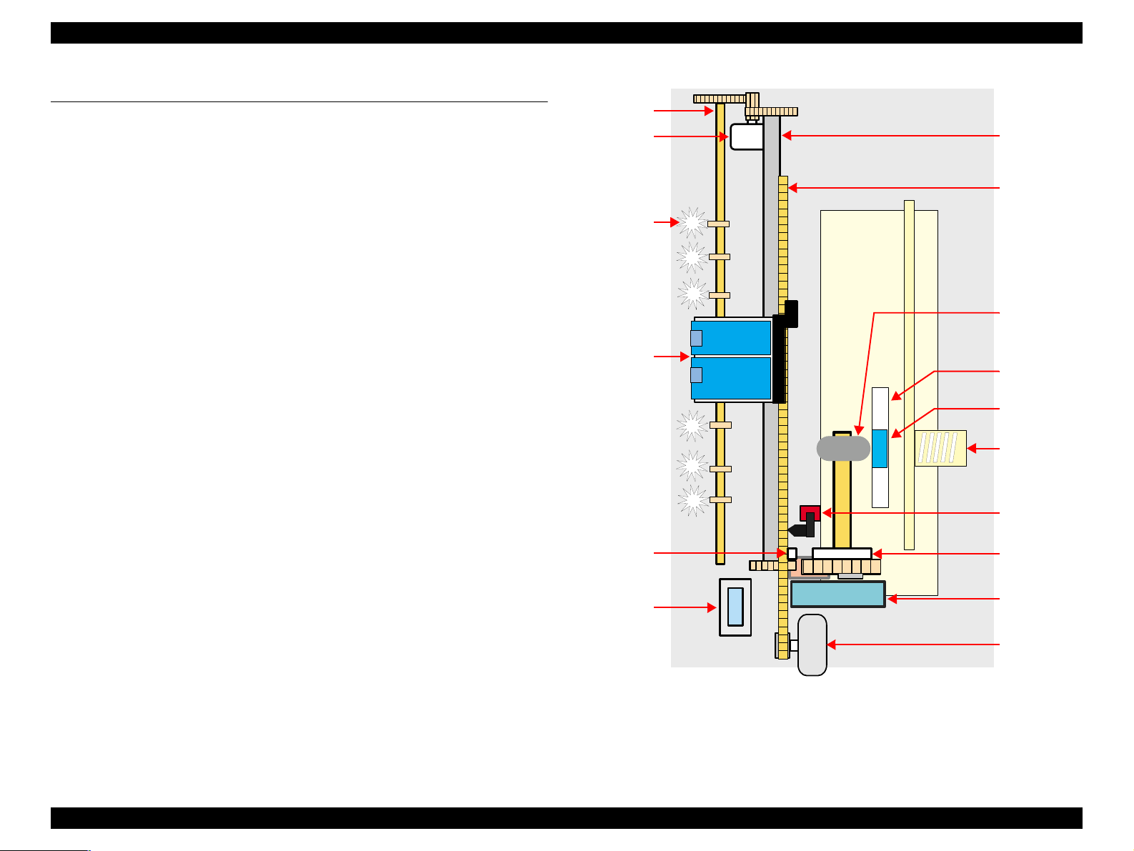
2.1.1 Printer Mechanism
The Printer Mechanism for the Stylus CX1500/ME100 is newly designed. But, the
basic component of the Printer Mechanism is almost the same as the previous printer
(Stylus C41/C42/C43/C44/C45/C46).
This printer consists of Print Head, Carriage Mechanism, Paper Loading Mechanism,
Paper Feeding Mechanism, Ink System.
Like the previous printers (Stylus C41/C42/C43/C44/C45/C46), the Stylus CX1500/
ME100 is equipped with two stepping motors; one for the Paper Loading/Feeding
Mechanism and the Pump Mechanism with the CR Lock Mechanism, and one for the
CR Mechanism. The ASF Unit for the Paper Loading Mechanism uses rear entry front
eject system. And, single LD Roller in Holder Shaft Unit loads a paper to the Printer
Mechanism.
Star Wheel
Carriage
Unit
Change
Lever
Cap Unit
LD Roller
Pad Holder
(Paper return
plate)
LD Pad
Compression
Spring
HP/PE Sensor
Clutch
mechanism
Pump Unit
CR Motor
Figure 2-1. Printer mechanism block diagram
OPERATING PRINCIPLES Overview 30
Page 31

EPSON Stylus CX1500/ME100 Revision A
2.1.2 Print Head
The Print Head is the same U-CHIPS type as the previous printer (Stylus C41/C42/
C43/C44/C45/C46), and makes it possible to perform multiple shot printing and
variable dot printing.
The Print Head nozzle configuration is as follows.
V Nozzle layout
Black : 48 nozzles x 1 row (nozzle pitch of row: 1/120 inch)
Color : 45 nozzles x 1 row (nozzle pitch of row: 1/120 inch)
The nozzle layout when viewed from the back surface of the Print Head is shown below.
16.5mm
2.2578mm (32/360")
#B48
(1/120")
0.2117mm
#B1
#Y15
#Y1
#C15
#C1
#M15
#M1
The Print Head has the Electric Poles (CSIC Connectors) to store the ink consumption
amount data into the CSIC chip mounted on the Ink Cartridge. By storing the ink
consumption amount data, this printer can detect the ink consumption status, such as
Ink Low/Out condition.
The basic operating principles of the Print Head, which plays a major role in printing,
are the same as the previous printer (Stylus C41/C42/C43/C44/C45/C46); on-demand
method which uses PZT (Piezo Electric Element). In order to uniform the ejected ink
amount, the Print Head has its own Head ID (6-digits code for this Print Head for
Stylus CX1500/ME100) which adjusts PZT voltage drive features.
So, you are required to store the Head ID pasted on the Print Head into the EEPROM
by using the Adjustment program when replacing the Print Head, the Main Board Un it,
the Printer Mechanism with new one. (Note: there are no resistor arrays to determine
the Head ID on the Main Board.) And then, based on the stored Head ID into the
EEPROM, the Main Board generates appropriate PZT drive voltage.
Figure 2-2. Nozzle layout
OPERATING PRINCIPLES Overview 31
Page 32

EPSON Stylus CX1500/ME100 Revision A
Following explains the basic components for the Print Head.
V PZT
PZT is an abbreviation of Piezo Electric Element. Based on the drive waveform
generated on the Main Board, the PZT selected by the nozzle selector IC on the
Print Head pushes the top of the ink cavity, which has ink stored, to eject the ink
from each nozzle on the nozzle plate.
V Electric Poles for CSIC
This Electric Poles connects the CSIC chip mounted on the Ink Cartridge. By
using this poles, current ink consumption amount data is red out from the CSIC
chip. And, the latest ink consumption amount data is written into the CSIC chip.
V Nozzle Plate
The plate with nozzle holes on the Print Head surface is called Nozzle Plate.
V Filter
When the Ink Cartridge is installed, if any dirt or dust around the cartridge needle
is absorbed into the Print Head, there is a great possibility of causing nozzle clog
and disturbance of ink flow, and alignment failure and dot missing finally. To
prevent this problem, a filter is set under the cartridge needle.
V Ink Cavity
The ink absorbed from the Ink Cartridge goes through the filter and then is stored
temporarily in this tank called “ink cavity” until PZT is driven.
Electric poles for CSIC
Needle
Filter
Nozzle selector boa rd
CSIC Memory chip
*Head ID for the Print Head is
stored to the EEPROM.
Ink cartridge
PZT
Nozzle plate
Cavity
Figure 2-3. Print Head sectional drawing
OPERATING PRINCIPLES Overview 32
Page 33

EPSON Stylus CX1500/ME100 Revision A
2.1.2.1 Printing Process
This section explains the process which the Printheads of On-Demand inkjet printers
eject ink from each nozzle.
1. Normal state:
When the printing signal is not output from the Main Board (C572 Main), or the
PZT drive voltage is not applied, the PZT does not change the shape. Therefore,
the PZT does not push the ink cavity. The ink pressure inside the ink cavity is kept
normal.(refer to Figure 2-4 (p.33): Normal state)
2. Ejecting state:
When the print signal is output from Main board (C572 Main), the nozzle selector
IC located on the Print Head latches the data once by 1-byte unit. Based on the
drive waveform (common voltage) generated on the Main Board, the PZT selected
by the nozzle selector IC pushes the top of the ink cavity. B y this operation, the in k
stored in the ink cavity is ejected from nozzles. (refer to Figure 2-4 (p.33):
Ejecting state)
Ink path PZT Ink cavity
Normal state
2.1.2.2 Printing Method
For printing dot system, the Stylus CX1500/ME100 has the following two kinds of
printing mode.
T Multiple shot printing
T Variable dot printing
The above two printing modes are automatically selected depending on the media and
the resolution setting of the printer driver. The following explains each printing mode.
V Multiple shot printing
This printing mode is developed to improve the print quality on plain paper or
transparencies in low resolution. The multiple shot printing mo de uses n ormal do t,
and the number of dot shot varies from 1 shot to maximum 3 shots depending on
the print data to enable to output sharp image even in a low resolution.
V Variable dot printing
This printing mode is developed to improve the print quality on exclusive paper.
This mode is basically the same as variable dot printing mode used on other
products; micro dot, middle dot and la rge dot compose this mode. The pri nting dot
size varies according to the print data and this mode enab les to output even sharper
image on exclusive paper.
Nozzle Nozzle plate
PZT drive voltage
Ejecting state
Figure 2-4. Print Head printing process
OPERATING PRINCIPLES Overview 33
Page 34

EPSON Stylus CX1500/ME100 Revision A
2.1.3 Carriage Mechanism
The Carriage Mechanism consists of CR Motor, Carriage Unit (including the Print
Head), Timing Belt and CR Home Position Sensor (HP/PE Sensor) etc. Following
figure shows you each component for the CR mechanism.
HP/PE Sensor
Carria ge Unit
Figure 2-5. Carriage Mechanism (Top view)
The following stepping motor controls the CR mechanism on this printer.
Table 2-1. Carriage Motor Specification
Items Specifications
Type 4-Phase/ 48-Poles PM Stepping motor
Drive Voltage +35.9V ± 5% (DRV IC voltage)
Coil Resistance 11.5Ω ± 10% (per phase at 25 degrees)
HP Detection Leve r
Timing Belt
CR Motor
The drive of the CR Motor is transmitted to the Carriage Unit via the Timing Belt.
And, the CR Home Position is detected with the HP/PE Sensor. This sensor is available
as the CR Home Position Sensor while the CR Motor operates in each sequence. (The
function of this sensor varies depending on the running condition of the motors. It is
available as the PE Sensor when the PF Motor operates in each sequence.)
When the detection plate molded on the Carriage Unit pushes down the HP Detection
Lever and the CR home position is detected with HP/PE Sensor, HIGH signal is output
to the CPU.
.
HP Detection Lever
HP Detection Lever
CR HP Detection Plate
Right side view
CR HP Detection Plate
Low signal
High signal
Figure 2-6. CR Home Position Detection
For your reference, in case that the CR home position is not detected with the HP/PE
Sensor although the Carriage Unit moves correctly, the printer indicates the “Fatal
error”. And also, in case that the Carriage Unit cannot move outside the home position
and the CR home position is not detected with the HP/PE Sensor, the printer indicates
the “Paper jam error”.
Inductance 15mH ± 20% (1KH 1Vrms)
Drive Method Bi-Polar drive
Driver IC A6615
OPERATING PRINCIPLES Overview 34
Page 35

EPSON Stylus CX1500/ME100 Revision A
2.1.4 Paper Loading/Feeding Mechanism
The following stepping motor controls the Paper loading/feeding mechanism on this
printer.
Table 2-2. PF Motor Specifications
Item Description
Motor type 4-Phase/ 96-Poles PM Stepping motor
Drive voltage +35.9V ± 5% (DRV IC voltage)
Coil Resistance 6.1Ω ± 10% (per phase at 25 degrees)
Inductance 8.7mH ± 20% (1kH 1Vrms)
Driving method Bi-Polar drive
Driver IC A6615
Left side view
PF Roller HP/PE Sensor
Spur Gear 60
(PF Roller)
Spur Gear 60
(EJ Roller)
The drive of the PF Motor is transmitted to the LD Roller Shaft and the PF Roller
through gears for the Paper loading/feedin g mechanism. The Paper loading mechanism
plays a role in loading a paper from the ASF Unit to the PF Roller. And also, the Paper
feeding mechanism plays a role in feeding a paper loaded from the ASF Unit. The
functions of the Paper loading/feeding mechanism varies depending on the rotational
direction of the PF Motor as the table below.
Table 2-3. ASF Unit Function & PF Motor Rotational Direction
Directions
Clockwise • Release the Change Lever from the Clutch mechanism
Counterclockwise
*2
: The PF Motor rotation direction = seen from the left side of the printer.
*2
Corresponding functions
• Pick up and feed a paper
• Set t he Change Lever on the Clutch mechanis m
Following shows you the transmission path of the PF Motor drive to the LD Roller, the
PF Roller and the EJ Roller. (The numbers in the following figure show you the order
of transmission path.)
Right side view
Spur Gear 10.8
(PF Roller)
Spur Gear
35.2
No paper
Detect a paper
6
1 1
PF Motor Pini on Gear
PF Motor
EJ Roller
1
Combination
Gear 18.28
Spur Gear 27.2
4
2
3
5
Combination
Gear 16.32
Spur Gear 25.6
PE Detection
Lever
Low signal
Paper
High signal
Note: The Clutch Gear is molded on the backside of the Spur Gear 35.2 such as Combination Gear.
Figure 2-7. Paper Loading/Feeding Mechanism
OPERATING PRINCIPLES Overview 35
Page 36

EPSON Stylus CX1500/ME100 Revision A
For your reference, the top or the end of a paper is usually detected with the HP/PE
Sensor. In case that the HP/PE Sensor cannot detect the top of a paper in the paper
loading sequence, the printer indicates the “Paper out error”. If the HP/PE Sensor
cannot detect the end of a paper in the paper feeding sequence, the p rinter ind icates th e
“Paper jam error”. As for the details, refer to Chapter 3 “Troubleshooting”.
2.1.4.1 Paper Loading Mechanism (ASF Unit)
The Paper loading mechanism consists of the Change Lever in the Pump Unit, the
Holder Shaft Unit (including the Clutch mechanism) and the ASF Unit.
The Change Lever and the Clutch mechanism play a major role in the Paper loading
mechanism as follows.
1. ASF home position detection function
The ASF Unit on this printer does not have the ASF Home Position Sensor.
Instead of the ASF Home Position Sensor, the Change Lever and the Clutch
mechanism is used to detect the ASF home position.
When the Change Lever is set on the C lutch mechanism with the co unterclockwise
rotation of the PF Motor pinion gear, the ASF home position is detected by this
lever for the paper loading operation. In this time, the printer cannot load a paper
from ASF Unit because the drive of the PF Motor is not transmitted to the LD
Roller Shaft.
2. Paper loading function
When the Change Lever is released from the Clutch mechanism with the
clockwise rotation of the PF Motor pinion gear, the ASF home position detection
function is changed over to the paper loading function. Therefore, the printer can
load a paper from ASF Unit because the drive of the PF Motor is transmitted to LD
Roller Shaft.
On this printer, the Paper Return Plate is built in ASF Unit instead of the Paper Return
Lever. The LD Pad is stacked on the Paper Return Plate, and it works with the tension
force of the Torsion Spring 29.1 mounted on the ASF Frame.
When an arc portion of the LD Roller pushes down this plate into the ASF Frame
during the paper loading sequence, a paper is loaded from the ASF Unit. A cutout
portion of the LD Roller releases this lever and this plate returns papers to the stand-by
position for next paper loading operation.
Following figures (refer to Figure 2-8 (p.37)/Figure 2-9 (p.38)) show you the ASF
paper loading sequence and the operation of each mechanism.
OPERATING PRINCIPLES Overview 36
Page 37

EPSON Stylus CX1500/ME100 Revision A
When the PF Motor
pinion gear rotates CW
direction (Right side
view), the Change Lever
pushes down the Clut ch
Lever as right figure and
the Clutch lock tooth is
disengaged from the
Clutch Gear. As the result,
the LD Roller Shaft dose
not rotate at all because
the drive of the PF Motor
is not transmitted. In this
time, the ASF Hopper is
also pushed down by the
ASF hopper release lever
on the LD Roller Shaft,
and the Paper Return Plate
is set to avoid that papers
are slipped do wn fro m th e
paper set position.
This position is the ASF
home position.
Step 1 (ASF Home Position)
Hopper & Paper Return Plate Condition
LD Roller Shaft
Paper Return Plate
Torsion Spring 29.1
ASF Frame
Gear Rotation Direction (Right side view)
Spur Gear 10.8
(PF Roller)
<PF motor drive transmission path for ASF home po siti on sett ing>
PF Motor pinion gear (CW) → Spur G ear 10. 8 (PF Roller) (CCW) →
Combination Gear 18.28 (CW) → Spur Gear 27.2 (CCW) →
Spur Gear 25.6 (CW) → Change L eve r (CW ) →
Combination Gear 16.32 (CCW) → Spur Gear 35.2 (CW)
* Above transmission pass = seen from the right side of
LD Roller
Change
Lever
Clutch
Lever
ASF Hopper
Release Lever
Hopper
Compression
Spring 2.50
Clutch
Clutch lock tooth
Clutch
Gear
the printer
Step 2
Hopper & Paper Return Plate Condition
Gear Rotation Direction (Right side view)
To Front side Extension spring
<PF Motor driver transmission path for Clutch Lever release>
PF Motor pinion gear (CCW) → Spur Gear 10.8 (PF Roller) (CW) →
Combination G ear 18.28 (CCW) →Spur Gear 27.2 (CW) →
Spur Gear 25.6 (CCW) → Change Lever (C CW ) →
Combination Gear 16.32 (C W ) → Spur Gear 35.2 (CCW)
* Above transmission pass = seen from the right side of
0.143
the print
When a paper is loaded
from the ASF Unit, the
Change Lever moves to
the front side of the
printer with the CCW
rotation (right side view)
of the PF Motor pinion
gear and releases the
Clutch Lever. As the
result, the Clutch turns
back to the engagement
position by the tension
force of the Extension
spring 0.143.
And, the Clutch Gear is
engaged with the Clutch
lock tooth to transmit the
drive of the PF Motor as
left figure. In this time,
the Change Lever is
locked instantaneously by
the protrusion on the
backside of the Carriage
Unit to change over from
the ASF home position
detection function to the
paper loading function
surely.
Figure 2-8. ASF Paper Loading Sequence (Step 1, 2)
OPERATING PRINCIPLES Overview 37
Page 38

EPSON Stylus CX1500/ME100 Revision A
The PF Motor pinion gear
rotates CW direction (right
side view), and the drive of
the PF Motor is transmitted
to the LD Roller Shaft
through the Clutch lock
tooth and the Clutch Gear.
After the LD Roller pushes
down the Paper Return Plate
into the ASF Frame, the
ASF Hopper is released by
the tension for ce of the
Compression Spring 2.50.
And, a paper is picked up
with the frictional force
between the LD Roller and
the Pad Hopper.
Step 3 Step 4
Hopper & Paper Return Plate Condition Hopper & Paper Return Plate Condition
ASF Hopper
Release Lever
Gear Rotation Direct ion (Ri ght side view) Gear Rotation Direction (Right side view)
<PF Motor driver transmission path for picking up a paper>
PF Motor pi ni on ge ar (CW) → Spur Gear 10.8 (PF Roller) (CCW) →
Combination Gear 18.28 (CW) → Spur Gear 27.2 (CCW) →
Spur Gear 25.6 (CW) → Change L eve r (CW) →
Combination Gear 16.32 (CCW) → Spur Ge ar 35.2 (CW)
* Above transmission pass = seen from the right side of
1
3
2
Compression
Spring 2.50
ASF Hopper Release Lever
LD Roller Shaft
the printer
1
ASF Frame
3
<PF Motor driver transmission path for paper loading>
PF Motor pinion gear (CW) → Spur Gear 10.8 (PF Roller) (CCW) →
Combination Gear 18 .2 8 (CW ) → Spur Gear 27.2 (CCW) →
Spur Gear 25.6 (CW) → Change Lever (CW) →
Combination Gear 16 .3 2 (CCW) → Spur Gear 35.2 (CW)
* Above transmission pass = seen from the right side of
2
Paper Return
Plate
the printe r
While the LD Roller rotates
CW direction (right si de
view) continuously, the top of
a paper is loaded to the PF
Roller. In this rotation, the
ASF Hopper returns to the
open position and the Paper
Return Plate is released from
the LD Roller. In this time,
this plate returns papers to the
stand-by position in ASF
Unit for next pape r loading
operation.
Then, when the rolling LD
Roller & the Clutch come at
the above “Step 1” position,
the Clutch Lever is locked
with the Change Lever again.
In this time, the drive of the
PF Motor is interrupted and
the drive is transmitted only
to the PF Roller side for the
paper feeding sequence.
Figure 2-9. ASF Paper Loading Sequence (Step 3, 4)
OPERATING PRINCIPLES Overview 38
Page 39

EPSON Stylus CX1500/ME100 Revision A
2.1.4.2 Paper Feeding Mechanism
The Paper feeding mechanism consists of PF Motor, PF Roller, EJ Roller, Paper End
Sensor (HP/PE Sensor) etc. The Paper feeding mechanism feeds a paper loaded from
ASF Unit by using pairs of roll ers .
1. One pair is the PF Roller and the Paper Guide Roller which is assembled in the
Paper Guide Upper/Left. The drive of the PF Motor is transmitted to the Paper
Guide Roller through the PF Roller.
2. Another pair is the EJ Roller and the Star Wheel which is assembled on the Front
Frame. The drive of the PF Motor is transmitted to the Star Wheel through the EJ
roller.
Left side view
Spur Gear 60
(PF Roller)
Paper Guide Roller Star Wheel
Spur Gear 60
(EJ Roller)
Following figure shows you the transmission path for the PF Roller & the Paper Guide
Roller and the EJ Roller & the Star Wheel.
The top of a paper is loaded to the PF Roller from the ASF Unit in the paper loading
sequence. And then, when the PF Motor pinion gear rotates CCW direction (left side
view), a paper is fed by the PF Roller & the Paper Guide Roller and the EJ Roller & the
Star Wheel in the printing operation & the paper feed sequence.
PF Roller
PF Motor
PF Motor pinion gear
EJ Roller
Transmission path (Left side view): PF Motor pinion gear (CCW) → Spur Gear 60 (PF Roller /EJ Roller) (CW)
Figure 2-10. Paper Feeding Mechanism
OPERATING PRINCIPLES Overview 39
Page 40

EPSON Stylus CX1500/ME100 Revision A
2.1.5 Ink System Mechanism
The Ink system mechanism consists of Pump mechanism with Carriage lock
mechanism and Capping mechanism with Wiper mechanism. Following table lists the
function for each mechanism.
Table 2-4. Function For Each Mechanism
Mechanism Function
Capping mechanism *
Wiper mechanism
Pump mechanism
Carriage lock mechanism
Note "*": Like the previous SPC (Stylus CX3500/CX3600/CX3650), this printer adopts the
valveless cap system. The air valve system used for the previous printer (Stylus
COLOR 740) have two functions by the CR position in the capping condition as
follows.
This is to cover the surface of the Print Head with the cap in
order to
This is to remove the foreign material and unnecessary ink on
the nozzle plate of the Print Head.
This is to eject the ink from the Ink Cartridge, the ink c avity and
the cap to the Waste Ink Pad.
This is to lock the Carriage Unit with the Change Lever while
the Carriage Unit is at the home position.
prevent the nozzle from increasing viscosity.
1) Valve closing condition (CL position)
By closing the air valve, the ink is forcibly absorbed from the ink cartridge
or the ink cavity by the Pump Unit and is ejected to the Waste Ink Pad while
the Carriage Unit is in the CL position.
2) Valve open ing cond ition (Ink absorption position)
By opening the Air valve, the negative pressure is decreased and only the
ink inside the Cap is ejected while the Carriage Unit is in the further right
side than the CL position. (the ink is not absorbed from the ink cartridge or
the ink cavity.)
The following shows you the Carriage Unit position for each condition easily.
Printing area
CR home position
CL position
(valve closing condition)
Ink absorption position
(valve opening condition)
But, on the valveless cap system, the above 2) operation is done outside the
capping position. The Carriage Unit moves outside the CR home position and
the pump absorbs the ink inside the Cap.
OPERATING PRINCIPLES Overview 40
Page 41

EPSON Stylus CX1500/ME100 Revision A
2.1.5.1 Capping Mechanism
The Capping mechanism covers the Print Head with the Cap to p revent the nozzle from
increasing viscosity when the printer is in stand-by state or when the printer is off.
When the Carriage Unit is in the
home position, the hook of the
Slider Lock Lever is not latched to
the dent of the Cap Frame.
In this time, the protrusion of the
Cap Slider does not reach the
rightmost position of the Cap
Frame.
Not latched
Step 1
Protrusion
Capping position
(CR home position)
V Wiper with the Cap Unit
The wiping operation is controlled by th e Carriage Unit movem ent. This operation
is usually performed with every CL sequence which is to absorb the ink from the
ink cartridge, the ink cavity by the Pump Unit. Following figure shows you the
mechanism for the wiping operation.
Step 2
Latched
Wiper setting position
The Carriage Unit moves to the wiper
setting position on the right mos t
position of the Cap Frame with
keeping the cap covered.
In this time, the hook of the Slider
Lock Lever is latched to the dent of
the Cap Frame.
When the wiping operation is
finished and the Carriage Unit
moves further to the left side,
the hook of the Carriage Unit
hits to the Slider Lock Lever.
In this time, the Slider Lock
Lever is released and the Cap
Slider returns to the bottom
position completely.
(The broken line is the position
of the Carriage Unit & the
Slider Lock Lever just before
being released.)
When the Car riage Unit m ov e s to the
left side from the wiper setting
position, the Cap Unit is pulled back
by the tension force of the
Spring 0.523
.
Extension
In this time, the Cap Unit is
automatically set to the wiping
position because the hook on the
Slider Lock Lever is latched to dent
of the Cap Frame. And, the wiping
operation is performed according to
the Carriage Unit movement.
Step 3
Protrusion of the Carriage Unit
Latched
Wiping position
Step 4
Released
Released position
(Bottom position)
Figure 2-11. Wiper Mechanism
OPERATING PRINCIPLES Overview 41
Page 42

EPSON Stylus CX1500/ME100 Revision A
2.1.5.2 Pump Unit Mechanism
The PF Motor also controls the Pump Unit mechanism (inclu ding the Change Lever ) as
well as the Paper loading/feeding mechanism. The drive of the PF Motor is always
transmitted to the Pump Unit. (And also, its drive is transmitted to the LD Roller
through the Clutch mechanism & the Change Lever.)
On this printer, the Pump Unit mechanism including the Change Lever plays a major
role expecting the ink eject operation. And, these operations control depending on the
PF Motor rotational direction as the following table below.
Table 2-5. PF Motor Rotational Direction & Ink System Mechanism
Directions * Functions
Clockwise
Counterclockwise • Non operation
Note "*": The PF Motor rotational direction = seen from the left side of the printer.
Spur Gear 60
(PF Roller)
• A bsorbs the ink by the Pump Unit
• Rel ease the Change Lever from the Clutch mechanism
Left side view Right side view
Spur Gear 60
(EJ Roller)
1. Ink eject operation (usual operation)
The ink is absorbed from the ink cartridge, the ink cavity and is ejected to the
Waste Ink Pad from the Cap when the Ink Tube is pressed by a roller in the Pump
Unit.
Following figure shows you the overview of the Pump Unit mechanism operation
Cap Unit Side
Note "*": The PF Motor rotational direction = seen from the right side of the printer.
Waste Ink Pad Side
Figure 2-12. Pump Mechanism
Cap UnitPump Unit
Change Lever Spur Gear 35.2
PF Roller
Combination
Gear 16.32
Spur Gear 25.6
PF Motor pinion gear
Combination
Gear 18.28
Spur Gear 27.2
(Pump Unit Gear)
Transmission Path: PF Motor pinion gear (CCW) → Spur Gear 60 (PF Roller & EJ Roller) (CW)→ Spur Gear 10.8 (CCW)
→ Combination Gear 18.28 (CW) → Spur Gear 27.2 (Pump Unit Gear) (CCW)
(* Above transmission pass = seen from the right side of the printer)
Figure 2-13. PF Motor Drive Transmission Path To The Pump Unit
OPERATING PRINCIPLES Overview 42
Page 43

EPSON Stylus CX1500/ME100 Revision A
2. Carriage lock operation by the Change Lever
Unlike the previous printer (Stylus COLOR 680), this printer does not have the
Carriage Lock Lever with the Wiper.
Instead of the Carriage Lock Lever, the Change Lever is set to the front side of the
printer while the Carriage Unit is in the CR home position.
(As for the detailed mechanism for setting the Change Lever, refer to Figure 2-8
(p.37) Step 2)
2.1.6 Ink Sequence
V Initial ink charge
After the printer is purchased and the power is turned on for the first time, the
printer must perform the Initial Ink Charge to charge the ink inside the ink cavity.
When the Initial Ink Charge is completed properly, the printer releases the flag
inside the EEPROM. Initial Ink Charge will take about 90 seconds for Stylus
CX1500/ME100. If the power is turned off during the Initial Ink Charge, the CL1’
will be performed at next power on timing.
V Manual Cleaning
The Stylus CX1500/ME100 provides four types of manual cleaning to clean air
bubbles, clogged ink with viscosity or foreign substances.
The following manual CL can be performed by the control panel operation, the
printer driver utility and the Adjustment program.
T Wiping ope ration
Wipes the nozzle plate by the rubber part on the Cap Unit.
T Flashing ope ration
Prevents color from mixing, and stabilizes ink surface inside the nozzle.
Independently of the printing path after t he previous CL, perform manu al CL from
CL1 to CL2 in order if the cumulative printing timer counter is less than 10min.
Only when the cumulative printing timer counter is more than 10min, execute only
CL1.
Additionally, if the I/C is Ink Low or Out condition, any manual cleaning is
prohibited and it is di splayed on th e LED indica tors.
OPERATING PRINCIPLES Overview 43
Page 44

EPSON Stylus CX1500/ME100 Revision A
V
Timer Cleaning
Like the previous SPC (Stylus CX3500/CX3600/CX3650), this printer dose not
have Timer IC and Lithium battery which is used for the backup power source for
Timer IC. So, this printer manages the printer off period or cleaning cycle by using
the following method.
The Printer Driver sends the timer command to the printer before printing. The
timer command is generated based on the PC’s timer and it consists of year, month
date, hour, minute and second. As soon as the printer receives the timer command
from the Printer Driver, the printer stores its command in the EEPROM. Then, it is
compared with the latest CL time which is stored in the EEPROM. And, in case
that the timer cleaning period is over the specific period, the printer performs the
timer cleaning automatically. In this time, the printer stores the timer command in
the EEPROM.
V Flashing
Two different flushing operations are executed for the following reasons.
T Pre-printing flushing
This is done before a start of printing to eliminate ink viscosity in the Print
Head nozzles.
T Periodic flushing
This is done during printing to prevent ink viscosity in the Print Head nozzles
from increasing.
OPERATING PRINCIPLES Overview 44
Page 45

EPSON Stylus CX1500/ME100 Revision A
2.2 Scanner Mechanism
The Scanner Mechanism of Stylus CX1500/ME100 is constructed of a Scanner
Carriage Unit, Scanner Motor, etc., in the same way as previous A4 size scanners.
2.2.1 Scanner Carriage Mechanism
2.2.1.1 Scanner Carriage Unit Overview
The Scanner Carriage Unit is constructed of a CIS Board (including linear CCD), Rod
Lens Array, LED (light source), etc.
V CIS Board
This takes the light information read from the document by the Rod Lens Array
and converts it to digital information using the linear CCD.
V Rod Lens Array
Many rod-shaped lenses are arranged in parallel, and the upright multiple images
of each lens is overlapped to form a single continuous image. Compared to a
regular lens, this has the special ability to reduce the distances between images.
It can project at 1 to 1 size for imaging a linear CCD with a width identical to an
A4 size document.
V LED
The unit uses an LED for an exposure light source. Using an LED eliminates the
need for an inverter board, and power consumption is reduced.
Pattern Label
Scanner Motor Timing Belt
Rod Lens Array
Scanner Carriage Unit
Figure 2-14. Scanner Mechanism
LED
Glass surfacePattern Label
CCD
Scanner Carriage Unit
CIS Board
Figure 2-15. Scanning Image
OPERATING PRINCIPLES Scanner Mechanism 45
Page 46

EPSON Stylus CX1500/ME100 Revision A
2.2.1.2 Scanner Carriage Unit Movement Overview
Scanning image is performed in the main scan direction (=1 line) by the CCD sensor
and in the sub-scan direction (=several lines) combined with Scanner Carriage Unit
movement. (refer to the figure below)
Line type, color CCD sensor can scan 1 line in main scan direction (parallel to the
Scanner Carriage Unit) by one time. When scanning next lines after the second line in
sub-scan direction, CR driving moves the Scanner Carriage Unit, which has CCD
sensor inside, and scan the other lines. The scanned data is sent to the control board.
The scanned data for “n” lines and “n-1” line are processed consecutively.
1st line 2nd line 1 pixel
Scanner Carriage
Unit
Sub-scan direction by Scanner Carriage Unit movement
Figure 2-16. Scanner Carriage Unit movement
Document
Main-scan
direction
Drive of the Scanner Motor is transferred to the Scanner Carriage Unit by the Scanner
Timing Belt. The Scanner Carriage Unit slides in the secondary scanning direction.
The Scanner Motor uses a stepping motor and drives using open loop control.
This scanner has no sensor mounted to detect the home position, which is a difference
from previous A-4 size scanners. When pattern label data fastened to the rear side of
Scanner Housing Upper is read, the Scanner Carriage Unit is determined to be in the
home positi on. (Refer to Figure 2-14 (p.45)/Figure 2-15 (p.45))
The table below shows the specifications for the stepping motor that controls the
Scanner Carriage Mechanism.
Table 2-6. Scanner Motor specifications
Item Description
Motor type TBD
Drive voltage TBDV (DC)
Coil resistance TBDΩ ± TBD% (per phase at 25 degrees)
Inductance TBDmH ± TBD% (1KH 1Vrms)
Driving method TBD
Driver IC TBD
OPERATING PRINCIPLES Scanner Mechanism 46
Page 47

TROUBLESHOOTING
CHAPTER
Page 48

EPSON Stylus CX1500/ME100 Revision A
3.1 Overview
This chapter describes unit-level troubleshooting. Refer to the flowchart in this chapter
to identify the defective unit and perform component level repair if necessary. This
chapter also explains motor coil resistance, sensor specification and error indication.
START
Unit-level troubleshooting
Unit repair
Assemble & Adjustment
END
Figure 3-1. Troubleshooting Flowchart
Table 3-1. Motor, Coil Resistance
Motor Location Check point Resistance
Table 3-2. Sensor Check Point
Sensor name Check point Signal level Switch mode
Off
HP/PE Sensor J11 / Pin 1 and 2
Thermistor
(THM)
TH1 (on the Head
driver board)
Less than 0.7V
More than 2.4VOn• Within CR home position
— 10K ( a t 25°C)
• Out of CR home position
• No paper
• Detect the paper
3.2 Error Indications and Fault Occurrence Causes
This section describes the LED indications, STM3 messages and fault occurrence
causes at occurrence of the following errors during any sequence/operation (e.g.
power-on sequence, paper feeding/loading sequence, ink sucking sequence).
NOTE: Errors caused by the Scanner Unit are not displayed on the STM3.
(STM3 displays the Printer’s errors only)
CR Motor J10
PF Motor J9
Scanner Motor J6
Pin 1 and 3
Pin 2 and 4
Pin 1 and 3
Pin 2 and 4
Pin 1 and 3
Pin 2 and 4
11.5Ω ± 10%
(at 25°C/phase)
6.1Ω ± 10%
(at 25°C/phase)
± TBD%
TBDΩ
°C / phase)
(at 25
TROUBLESHOOTING Overview 48
Page 49

EPSON Stylus CX1500/ME100 Revision A
Table 3-3. Error Indications and Fault Occurrence Causes
Printer Status Co mmunication error Ink low Paper out
Power —— —
Paper —— On
Ink —Blink —
1 —— —
Number
of copies
Indications
Paper
Type
Fit to Page —— —
2 —— —
3 —— —
1 —— —
2 —— —
Status Monitor
3 Message
This error is detected when the
Fault
Occurrence
Cause
Note : “–” : Don’t care
SPC cannot communicate with
the PC correctly.
This error is detected when the ink consumption amount reaches about 85%.
Note :
Even if this error is indicat ed on th e STM3, you ca n continu e the p rinting
until I/C becomes Ink Out condition. However, the Head Cleaning
operation cannot be done so that the remaining ink is low condition.
This error is detected when the top of a paper is not detected with the
PE Sensor in the paper loading sequence.
TROUBLESHOOTING Error Indications and Fault Occurrence Causes 49
Page 50

EPSON Stylus CX1500/ME100 Revision A
Table 3-3. Error Indications and Fault Occurrence Causes
Printer Status Ink out or No Ink cartridge CSIC error
Power — —
Paper — —
Ink On On
1 — —
Number
of copies
Indications
Paper
Type
Fit to Page — —
2 — —
3 — —
1 — —
2 — —
Status Monitor
3 Message
This error is detected when;
Fault
Occurrence
Cause
Note : “–” : Don’t care
• The ink consumpt ion amount reaches 100%.
• The ink cartridge is defective.
The slight amount of the ink is remaining in the I/C even if the Ink
Out error is detected. This is to prevent the Print Head nozzle from
the printing operation without firing the ink.
This error is detected when data from CSIC cannot be read normally or when data cannot be written to
CSIC.
TROUBLESHOOTING Error Indications and Fault Occurrence Causes 50
Page 51

EPSON Stylus CX1500/ME100 Revision A
Table 3-3. Error Indications and Fault Occurrence Causes
Printer Status Incorrect I/C Paper jam Maintenance request Fatal error
Power — Blink Off On
Paper —OnOnOn
Ink On — Off On
Number
of copies
Indications
Paper
Type
Fit to Page ——OffOn
1 ——OffOn
2 ——OffOn
3 ——OffOn
1 ——OffOn
2 ——OffOn
Status Monitor
3 Message
Fault
Occurrence
Cause
Note : “–” : Don’t care
This error is detected when;
• An unsupported i nk cartridge has been installed.
• An ink cartridge with a different destination has been installed.
This error is detected when the PE
Sensor cannot properly detect the
paper bottom edge durin g feedin g
of paper.
This error is detected when the
Waste Ink Counte r exceeds the
preset counter value.
This error is detected when it is
determined that the printer cannot
operate properly.
(CR error, PF error, etc.)
TROUBLESHOOTING Error Indications and Fault Occurrence Causes 51
Page 52

EPSON Stylus CX1500/ME100 Revision A
3.3 Troubleshooting
You can identify the troubles by using the checklist in this section after confirming the LED indication on the SPC. If you connect the SPC to your PC and see an error message on
the STM3, you can short the total repair time. And, when you find out the defective parts, replace them by referring the Chapter 4 “Disassembly ”. The following tables describe the
error check points.
Table 3-4. Check point for the communication error according to each phenomenon
Occurrence
timing
CR position
Detailed phenomenon
Defective
unit/part name
Check point Remedy
1. Check if the Panel Connector Cable is not damaged. 1. Replace the Panel Board with a new one.
Panel Board
•Power on
•Anywhere
When turning on the power, the SPC
does not operate at all.
Panel Unit
Panel Connector Cable
2. Check if the Panel Board is not damaged. 2. Replace th e Panel Board with a new one.
TROUBLESHOOTING Troubleshooting 52
Page 53

EPSON Stylus CX1500/ME100 Revision A
Table 3-4. Check point for the communication error according to each phenomenon
Occurrence
timing
CR position
•Power on
•Anywhere
Detailed phenomenon
When turning on the power, the SPC
does not operate at all.
Defective
unit/part name
PS Board Unit
Check point Remedy
1. Check if the PS Board Connector Cable is connected to
the J1 on the Main Board.
J1
Main Board Unit
2. Check if the PS Board Connector Cable/PS Board Unit
is not damaged.
PS Board Connector Cable
1. Connect the PS Board Connector Cable to J1
on the Main Board.
2. Replace the PS Board Unit with new one.
* If the problem is not solved, replace the
Main Board Unit with a new one.
PS Board Unit
TROUBLESHOOTING Troubleshooting 53
Page 54

EPSON Stylus CX1500/ME100 Revision A
Table 3-4. Check point for the communication error according to each phenomenon
Occurrence
timing
CR position
• Operation
•–
Detailed phenomenon
When turning on the power, the
power on sequence is performed
correctly. But, when any printer job
is sent to the SPC, a communication
error is indicated with STM3.
Defective
unit/part name
USB Cable
Main Board Unit
Check point Remedy
1. Check if the USB Cable is connected between the SPC
and the PC.
1. Check if an incorrect model name is not stored into th e
address of the EEPROM on the Main Board.
2. Check if the Panel Connector Cable is connec ted to the
J4 on the Main Board.
Panel Unit
1. Connect t he US B Cable to the SPC and the
PC.
1. Use the Adjustment Program to write the
correct value to the EEPROM address.
2. Connect the Panel Connector Cable to J4 on
the Main Board.
Occurrence
timing
CR position
•Power on
•Inside HP
•Power on
•Anywhere
Table 3-5. Check point for the error before the initial ink charge according to each phenomenon
Detailed phenomenon
The SPC does not perform th e initial i nk
charge and an error is indicated with
LEDs and STM3.
The SPC does not perform the ink
replacement CL and an error is indi cated
with LEDs and STM3.
The SPC does not perform the printing
operation and an error is indicated with
LEDs and STM3.
Defective
unit/part name
Ink Cartridge
Main Board Unit
Ink Cartridge
Ink Cartridge
J4
1. Chec k if the Ink Cartridge can be used by installing it to
other SPC.
1. Check if an incorrect data is not store d in to th e a d dress o f
the EEPROM on the Main Board.
1. Chec k if the Ink Cartridge can be used by installing it to
other SPC.
1. Check if the ink is remaining in the Ink Cartridge. 1. Replace the Ink Cartridge with a bran d-new
2. Chec k if the Ink Cartridge can be used by installing it to
other SPC.
Panel Connector Cable
Check point Remedy
1. Replace the Ink Cart ridge with a brand-new
one.
1. Set the proper destination by using
Adjustment Program .
1. Replace the Ink Cart ridge with a brand-new
one.
one.
2. Replace the Ink Cart ridge with a brand-new
one.
TROUBLESHOOTING Troubleshooting 54
Page 55

EPSON Stylus CX1500/ME100 Revision A
Table 3-6. Check point for the paper out error according to each phenomenon
Occurrence
timing
CR position
• Operation
•–
Detailed phenomenon
The LD Roller cannot pi ck up paper
although the LD Roller attempt to rotate
correctly.
Defective
unit/part name
Holder Shaft Unit
Check point Remedy
1. Check if a ny paper dust is not adhered to the surface of
the LD Roller.
LD Roller
1. Check if the Hopper operates correctly in the paper
loading sequence.
Hopper
1. Set a clean ing sheet in the ASF Unit up side
down. Then holding the top edge, try to load
the paper from the Printer driver. The micro
pearl on the LD Roller surface is removed. To
remove severe smear, staple a cloth
moistened with alco hol to a post card and
clean the roller in the same manner.
Non-adhesive A rea
CL Sheet
Adhesive Area
This side down
(Use a post card
for the base sheet)
Staplers
Cloth mois t ened
with alcohol
* If the problem is not solved, replace the
Holder shaft unit with new one.
1. Reassemble the Compression spring 2.50
between the ASF Frame and the Hopper.
The Hopper does not operate during the
paper loading sequence although the LD
Roller rotates to load paper from the
ASF Unit
ASF Unit.
Compression spring
2.50
TROUBLESHOOTING Troubleshooting 55
Page 56

EPSON Stylus CX1500/ME100 Revision A
Table 3-6. Check point for the paper out error according to each phenomenon
Occurrence
timing
CR position
Detailed phenomenon
When a top of a paper at the correct
timing during the paper loading
sequence, the paper is ejected
immediately without setting the paper
setting position for printing.
Defective
unit/part name
ASF Unit
Check point Remedy
1. Check if the Paper Return Plate operates correctly in the
paper loading sequence.
Torsion Spring 29.1 Paper Return Plate
1. Set the Torsion Spring 2 9.1 between the AS F
Frame and the Paper Return Plate.
• Operation
•–
The drive of the PF Motor is not
transmitted to the LD Roller Shaft.
Holder Shaft Unit
1. Check if the Extension Spring 0.143 does not come off in
the Clutch mechanism.
Extension Spring 0.143
2. Check if the Clu tch does not come off from the dowel of
the LD Roller Shaft.
Clutch tooth
Dowel
3. Chec k if the Clutch tooth is not damaged. 3. Replace the Holder Shaft Unit with a new
4. Check if the Clutch is not damaged. 4. Replace the Holder Shaft Unit with a new
1. Reassemble the Extension spring 0.143 in the
Clutch mechanism.
2. Reassemble the round portion of the Clutch
on the dowel of the LD Roller Shaft.
one.
one.
TROUBLESHOOTING Troubleshooting 56
Page 57

EPSON Stylus CX1500/ME100 Revision A
Table 3-6. Check point for the paper out error according to each phenomenon
Occurrence
timing
CR position
Detailed phenomenon
Defective
unit/part name
Check point Remedy
1. Check if the Com pressi on Spri ng 1 .764 do es no t come o ff
in the Change Lever.
Change Leve r
1. Replace the Ink System Unit with a new one.
• Operation
•–
The drive of the PF Motor is not
transmitted to the LD Roller Shaft.
The LD Roller is not set to the ASF
home position and paper is always
loaded from the ASF Unit during the
paper loading sequence.
Although the printer enters standby
mode normally after power-on, the PF
Motor does not rotate when a pr int job is
transmitted to the SPC.
Ink System Unit
Ink System Unit
PF Motor
Compression Spring 1.764
1. Check if the tip of the Change Lever is not damaged. 1. Replace the Ink System Unit with a new one.
1. Check if the PF Motor Connector Cable is connected to
J9 on the Main Board.
J9
PF Motor
Connector Cable
2. Check if the coil resistance of the PF Motor is about 6.1Ω
1. Connect the PF Motor Connector Cable to J9
on the Main Board.
2. Replace the PF Motor with a new one.
by using tester (refer to Table 3-1).
3. Check if th e PF Motor Connector Cable is not damaged. 3. Replace t he PF Motor with a new one.
TROUBLESHOOTING Troubleshooting 57
Page 58

EPSON Stylus CX1500/ME100 Revision A
Table 3-7. Check point for the No ink cartridge/CSIC error/Incorrect ink cartridge according to each phenomenon
Occurrence
timing
CR position
Detailed phenomenon
Defective
unit/part name
Ink Cartridge
Check point Remedy
1. Check if Ink Cartridge is properly installed. 1. Install the Ink Cartridge properly.
2. Chec k if the Memory Chip i s not disconnected or not
2. Replace the Ink Cart ridge with a new one.
chipped.
Memory Chip
1. Check if the Head FFC is connected to connector on the
CSIC Board.
Head FFC
1. Connect the Head FFC to connector on the
CSIC Board.
•Power on
•Inside HP
After the Carriage has detected the HP,
an error is displayed.
CSIC Boa rd
Connector
2. Check if th e CSIC Board is not damaged. 2. Replace the Carria ge Unit with a new one.
1. Check if the CSIC Con nector is not damaged. 1. Replace the Carriage Unit with a ne w one.
CSIC Board
CSIC Connector
CSIC Connectors
TROUBLESHOOTING Troubleshooting 58
Page 59

EPSON Stylus CX1500/ME100 Revision A
Table 3-8. Check point for the paper jam error according to each phenomenon
Occurrence
timing
CR position
• Operation
• Outside HP
Detailed phenomenon
The paper feeding sequence is
performed without loading paper in the
paper loading sequence.
Defective
unit/part name
ASF Unit
Holder Shaft Unit
Check point Remedy
1. Check if the ASF Unit is properly installed. 1. Install the ASF Unit properly.
2. Check if the Paper Return Plate operates correctly in the
paper loading sequence.
Paper Return PlateTorsion Spring 29.1
1. Check if the Torsion Spring 0.22 is properly installed. 1. Set the Torsion Spring 0.22 between the
Torsion Spring 0.22
2. Set the Torsion Spring 2 9.1 between the AS F
Frame and the Paper Return Plate.
Holder Shaft and the PE Sensor Lever.
HP/PE Sensor
PE Sensor Lever
When turning on the power, the Carriage
Unit move to the home position
correctly. But, the paper feeding
sequence is performed without loading
paper in the paper loading sequence.
* The Carriage Unit can move to home position even if the Torsion spring 0.22 come s off or the HP/P E sensor is no t co rrec tly placed. However, the HP Sensor lever keeps the high signal condition
in the next operation. Therefore, the paper jam error is detected.
Holder Sh af t Unit*
1. Check if the Torsion Spring 0.22 is properly installed. 1. Set the Torsion Spring 0.22 between the
Holder Shaft and the PE Sensor Lever.
TROUBLESHOOTING Troubleshooting 59
Page 60

EPSON Stylus CX1500/ME100 Revision A
Table 3-8. Check point for the paper jam error according to each phenomenon
Occurrence
timing
CR position
Detailed phenomenon
Defective
unit/part name
Check point Remedy
1. Check if the PF Motor Connector Cable is connected to
J9 on the Main Board.
J9
PF Motor
Connector Cable
1. Connect the PF Motor Connector Cable to J9
on the Main Board.
• Operation
• Outside HP
• Operation
•–
The printer starts to perform paper
ejection operation at power-on causing
an error indication.
When a top of a paper at the correct
timing during the paper loading
sequence, the paper is ejected
immediately without setting the paper
setting position for printing. But, in this
time, next paper is loaded to the PE
Sensor Lever.
PF Motor
ASF Unit
2. Check if the coil resistance of the PF Motor is about 6.1Ω
by using tester (refer to Table 3-1).
3. Check if th e PF Motor Connector Cable is not damaged. 3. Replace t he PF Motor with a new one.
1. Check if the Paper Return Plate operates correctly in the
paper loading sequence.
Paper Return PlateTorsion Spring 29.1
2. Replace the PF Motor with a new one.
1. Set the Torsion Spring 2 9.1 between the AS F
Frame and the Paper Return Plate.
TROUBLESHOOTING Troubleshooting 60
Page 61

EPSON Stylus CX1500/ME100 Revision A
Table 3-8. Check point for the paper jam error according to each phenomenon
Occurrence
timing
CR position
• Operation
•–
Detailed phenomenon
The leading edge of paper does not go
through between the EJ Roller and the
Star Wheel .
Defective
unit/part name
Front Frame**
EJ Roller
Check point Remedy
1. Check if th e Star Wheel does not come off. 1. Replace the Front Frame with a new one.
Front Frame
2. Check if the Front Frame is correctly assembled. 2. Reassemble the Front Frame correctly.
3. Check if the Front Frame is not bent down. 3. Replace the Front Frame with a new one.
1. Check if the EJ Roller is correctly assembled. 1. Reassemble the EJ Roller correctly.
Spur Gear 60
EJ Roller
2. Check if the Spur Gear 60 does not come off. 2. Replace the EJ Roller with a new one.
A paper is loaded from the ASF Unit,
and it is fed correctly. But, the paper
feeding sequence is performed without
loading a paper from the next paper
loading sequence.
• Operation
•–
** In case that the paper jam error occurs in each operation, the jammed paper contacts the nozzle surface of the Print Head and the Print Head may be damaged.
The leading edge of paper is not loaded
to the PF Roller Unit.
Holder Shaft Unit
Paper Guide
Upper**
1. Check if the Torsion Spring 0.22 for the PE Sensor Lever
does not come off.
1. Check if the Paper Guide Upper is correctly assembled. 1. Reassemble the Paper Guide Upper to the
Paper Guide Upper
1. Set the Torsion Spring 0.22 for the PE Sensor
Lever to the suitable position.
Main Frame correctly.
TROUBLESHOOTING Troubleshooting 61
Page 62

EPSON Stylus CX1500/ME100 Revision A
Table 3-9. Check point for the Fatal error according to each phenomenon
Occurrence
timing
CR position
Detailed phenomenon
Defective
unit/part name
Check point Remedy
1. Check if the CR Motor Connector Cable is connected to
J10 on the Main Board.
J10
1. Connect the CR Motor Connector Cable to
J10 on the Main Boar d.
•Power on
•Anywhere
When turning on the power, the CR
Motor does not operate at all.
When turning on the power, the Carriage
Unit collides to the Change Lever
located to the front side of the printer.
CR Motor
Holder Shaft Unit
CR Motor
Connector Cable
2. Check if the coil resistance of the CR Motor is about
2. Replace the CR Motor with a new one.
11.5Ω by using test er (refer to T able 3-1).
3. Check if the CR Motor Connect or Cable is not damage d. 3. Replace the CR Motor with a new one.
1. Check if the Paper Return Plate disturbs the rotation of
1. Reassemble the ASF Unit to the SPC.
the LD Roller.
LD Roller
Paper Return Plate
TROUBLESHOOTING Troubleshooting 62
Page 63

EPSON Stylus CX1500/ME100 Revision A
Table 3-9. Check point for the Fatal error according to each phenomenon
Occurrence
timing
CR position
Detailed phenomenon
Defective
unit/part name
Check point Remedy
•Power on
•Anywhere
When turning on the power, the Carriage
Unit collides to the Change Lever
located to the front side of the printer.
The Carriage Unit collides with the
Paper Guide Upper when power is
turned on.
Ink System Unit
Paper Guide
Upper
1. Check if the Com pressi on Spri ng 1 .764 do es no t come o ff
in the Change Lever.
Change Leve r
Compression Spring 1.764
1. Check if the Paper Guide Upper is correctly assembled. 1. Reassemble the Paper Guide Upper to the
Paper Guide Upper
1. Check if the Slider Lock Lever is correctly released by
the CR movement.
1. Replace the Ink System Unit with a new one.
Main Frame correctly.
1. Replace the Front Frame with a new one.
Slider Lock Lever
• Operation
•–
The Carriage Unit climbs over the Slid er
Lock Lever set to the wiping position
and the Carriage Unit collides to its
lever.
Front Frame
Main Frame
1. Check if the Slider Lock Lever is correctly released by
the CR movement.
1. Replace the Pri nter Mechanism with a new
one.
TROUBLESHOOTING Troubleshooting 63
Page 64

EPSON Stylus CX1500/ME100 Revision A
3.3.1 Superficial Phenomenon-Based Troubleshooting
This section explains the fault locations of the error states (print quality and abnormal noise) other than the error states (LED and STM3) in the previous section.
Table 3-10. Check point for multiple sheets of paper are always loaded without LEDs and STM3
Occurrence
timing
CR position
Detailed phenomenon
Defective
unit/part name
Check point Remedy
1. Check if the Paper Return Plate operates correctly in the
paper loading sequence.
1. Set the Torsion Spring 2 9.1 between the AS F
Frame and the Paper Return Plate.
• Operation
•–
Occurrence
timing
CR position
•Anywhen
•Anywhere
The LEDs and STM3 are not indicating
error conditions. But, multiple sheets of
paper are always loaded from the ASF
Unit.
Detailed phenomenon
The abnormal noise occurs at the first
power on timing and dur ing each
operation although the prin tin g
operation is performed.
The bottom of the Carriag e Unit contacts
the surface of the Front Frame
The Carriage Unit collides to the Paper
Guide Upper during eac h operation.
Paper Return PlateTorsion Spring 29.1
ASF Unit
Table 3-11. Check point for the abnormal noise
Defective
unit/part name
Front Frame
Main Frame
Ink System Unit 1. Check if the Change Lever moves smoothly. 1 . Replace the Ink System Unit wit h a new one.
Front Frame
Paper Guide Upper
1. Check if th e grease on the Front Frame is sufficient. 1. Wipe off the remaining grease on the Front
1. Check if the grease on the CR Guide Rail is sufficient. 1. Wipe off the remaining grease on the CR
1. Check if the Front Frame is not bent up. 1. Replace the Front Frame with a new one.
1. Check if the Paper Guide Upper Unit is attached securely.
(Check if it interferes with the Carriage Unit)
Check point Remedy
Frame and lubricate it on its frame.
Guide Frame and lubricate it on its frame.
1. Reassemble the Paper Guide Upper to the
Main Frame.
TROUBLESHOOTING Troubleshooting 64
Page 65

EPSON Stylus CX1500/ME100 Revision A
Table 3-12. Check point for poor scanne d image quality
Scanned image
Quality State
• Scanned image is
not clear.
Detailed phenomenon
There are dusts on the Document Glass.
(white dots appear on the scanned
image)
There are dusts on the LED in the Rod
Lens Array.
(vertical stripes appear on the scanned
image)
The LED of CIS Unit does not light up. CIS Unit 1. Check if the LED lights up. 1. Replace the CIS Unit with new one.
Defective
unit/part name
Scanner Housing
Upper
Scanner Carriage
Unit
Document 1. Check i f a document to be copied is set correctl y. 1. Set the document correctly.
1. Check if th ere is not any dust on the Document Glass. 1. Remove the extraneous matter from the
1. Check if th ere is not any dust on the LED. 1. Remove the extraneous matter from the Rod
1. Check if the Scanner Carriage FFC is connected to J8 on
the Main Board.
Check point Remedy
Document Glass.
(Refer to the Chapter 6 “MAINTENANCE”.)
Lens Array (blow away the dusts).
1. Connect the Sc anner Carriage FFC to J8 on
the Main Board.
J8
• Nothing is
scanned.
Making a copy result s in all black
printout.
Scanner Carriage
FFC
Scanner Carriage FFC
2. Check if the Scanner Carriage FFC is not damaged. 2. Replace the Scanner Carriage FFC wit h a
new one.
TROUBLESHOOTING Troubleshooting 65
Page 66

EPSON Stylus CX1500/ME100 Revision A
Table 3-12. Check point for poor scanne d image quality
Scanned image
Quality State
• Nothing is
scanned.
Detailed phenomenon
When made a co py , th e pa pe r is ej ected
without printing.
Defective
unit/part name
Scanner Motor
Check point Remedy
1. Chec k if the Scanner Mot or Connector Cable i s
connected to J6 on the Main Board.
J6
Scanner Motor
Connector Cable
2. Check if the coil resistance of the Scanner Motor is abo ut
TBDΩ by using the tester (refer to Tab le 3-1).
1. Connect the Sc anner Motor Connector Cable
to J6 on the Main Board.
2. Replace the Scanner Motor with a new one.
Scanner Motor
3. Chec k if the Scanner Mot or Connector Cable i s not
damaged.
3. Replace the Scanner Motor with a new one.
TROUBLESHOOTING Troubleshooting 66
Page 67

EPSON Stylus CX1500/ME100 Revision A
Table 3-13. Check point for the poor printing quality
Print Quality
State
Detailed phenomenon
Defective
unit/part name
Check point Remedy
1. Check if there i s no t an y f or e i g n material/da mage around
the seal rubber part on the Cap Unit.
Seal rubber part
1. Remove the foreign material around the seal
rubber parts carefully.
• Dot missing an d
mixed colors
Ink is scarcely ejected to the Cap from
the Print Head.
Ink is ejected to the Cap from the Print
Head, but the SPC does not recover from
the error after cleaning or ink change.
Ink System Unit
(Cap Unit)
2. Check if the Spring under the Cap does not come off. 2. Replace the Ink System Unit with a new one.
1. Check if it returns to normal by performing CL operation
or replacing the Ink Cartridge.
Print Head
2. Check if th e Print Head is not damaged. 2. Replace t he Print Head with a new one.
Cleaner Blade
Main Board Unit 1. Check if the Main Board Unit is not damaged. 1. Replace the Main Board Unit with a new one.
1. Check if the Cleaner Blade does not have paper dust or
bending.
1. Perform CL operation and the Ink Cartridge
replacement specified times.
If it doesn’t work, change the Print Head with
a new one.
1. Replace Ink Sy st em Unit with a new one.
TROUBLESHOOTING Troubleshooting 67
Page 68

EPSON Stylus CX1500/ME100 Revision A
Table 3-13. Check point for the poor printing quality
Print Quality
State
• White streak /
abnormal
discharge
Detailed phenomenon
Ink is ejected to the Cap from the Print
Head, but printing is not done at all after
cleaning or ink chan ge , or ab normal
discharge occurs.
Defective
unit/part name
1. Check if the Head FFC is securely connected to the Print
Head Connectors and the Main Board Connect ors (J12).
Print Head
Check point Remedy
1. Connect th e Head FFC to the Print Head and
the Main Board Connectors.
J12
Head FFC
Head
Connectors
FFC
2. Check if th e Head FFC is not damaged. 2. Replace the Head FFC with a new one .
Print Head
1. Check if it returns to normal by performing CL operation
or replacing the Ink Cartridge.
1. Perform CL operation and the Ink Cartridge
replacement specified times.
If it doesn’t work, change the Print Head with
a new one.
Main Board Unit 1. Check if the Main Board Unit is not damaged. 1. Replace the Main Board Unit with a new one.
TROUBLESHOOTING Troubleshooting 68
Page 69

EPSON Stylus CX1500/ME100 Revision A
Table 3-13. Check point for the poor printing quality
Print Quality
State
• White streak/
color unevenness
occurrence
Detailed phenomenon
Vertical banding appears against the CR
movement direction. And, it looks like
uneven printing.
CR movement
direction
[Note]
If the problem is not solved, replace the
CR Motor with a new one.
Defective
unit/part name
Adjustment
Print Head
Carriage Unit /
Main Frame
Front Frame
Check point Remedy
1. For printing in the Bi-D mode, check if Bi-D Adjustment
has been performed properly.
1. Check if each segment is printed correctly in the Nozzle
Check Pattern.
1. Check if there is not any foreign material on the surface
of the CR Guide Rail.
2. Check if the grease is enough on the surface of the CR
Guide Rail.
1. Check if there is not any foreign material on the surface
of the Front Frame.
2. Check if the Front Frame is lubricated with enough
grease.
3. Chec k if the Front Frame has not been deformed. 3. Replace the Front Frame with a new one.
1. Perform Bi-D Adjustment to eliminate
displacements between the up per and lower
rules. (Refer to Chapter 5 "ADJUSTMENT".)
1. Perform Head Cleaning and check the Nozzle
Check Pattern. (Refer to Chapter 5
“ADJUSTMENT”.)
If the problem is not solved, replace the Print
Head with a new one.
1. Remove foreign objects from surface of the
CR Guide Rail.
2. After wiping the grease on the CR Guide Rail
and the Carriage with a dry, soft cloth, coat it
with grease (G-58). (Refer to Chapter 6
“MAINTENANCE”.)
1. Remove foreign matter from the Front Frame.
2. After wiping t he grease on the Front Frame
with a dry, soft cloth, coat it with grease (G-
58). (Refer to Chapter 6
“MAINTENANCE”.)
TROUBLESHOOTING Troubleshooting 69
Page 70

EPSON Stylus CX1500/ME100 Revision A
Table 3-13. Check point for the poor printing quality
Print Quality
State
• White streak/
color unevenness
occurrence
Detailed phenomenon
Micro banding appears horizontally
against the CR movement direction and
it appears with the same width.
CR movemen t
direction
[Note]
If the problem is not solved, replace the
PF Motor with a new one.
The Star wheel mark against the CR
movement direction.
Defective
unit/part name
Printer driver &
exclusiv e pa per
Print Head
PF Roller Unit
Check point Remedy
1. Check if the suitable paper is used according to the printer
driver setting.
1. Check if each segment is printed correctly in the Nozzle
Check Pattern.
1. Check if there is not any foreign material on the surface
of the PF Rol l er Unit.
PF Roller Unit
2. Check if the PF Roller Unit is not damaged. 2. Rep l ace the Printer Mechanism with a new
1. Check if th e Star Wheel does not come off. 1. Replace the Front Frame with a new one.
2. Check if th e surface of the Front Frame is flat. 2. Replace the Front Frame with a new one.
1. Use the suitable paper according to the printer
driver setting.
1. Perform the Head Cleaning and check the
Nozzle Check Pattern. (Refer to Chapter 5
“ADJUSTMENT”.)
If the problem is not solved, replace the Print
Head with a new one.
1. Clean the surface of the PF Roller Unit
carefully with the soft cloth.
one.
Front Frame
Printing is blurred.
Printer driver &
exclusiv e pa per
Print Head
1. Check if the suitable paper is used according to the printer
driver setting.
1. Check if the correct Head ID is stored into the EEPROM
by using the Adjust ment Program.
1. Use the suitable paper according to the printer
driver setting.
1. Input 6 digits code of the Head ID into the
EEPROM by using the Adjustment Program.
TROUBLESHOOTING Troubleshooting 70
Page 71

EPSON Stylus CX1500/ME100 Revision A
Table 3-13. Check point for the poor printing quality
Print Quality
State
•Print start
position slip
Detailed phenomenon
The printing operation is correctly
performed. But, the top margin is
insufficient than usual one.
Ink stain occurs at the back, top end or
bottom end of the print paper.
Defective
unit/part name
Holder Shaft Unit
Housing Lower
(inner)
Check point Remedy
1. Check if a ny paper dust is not adhered to the surface of
the LD Roller.
LD Roller
1. Check if the Housing Lower (inner) does not have ink
stain.
Housing Lower (inner)
1. Set a cleaning shee t i n th e AS F up side
down.
Then holding the top edge, try to load the
paper from the Printer driver. The micro pearl
on the LD Roller surface is removed. To
remove severe smear, staple a cloth
moistened with alco hol to a post card and
clean the roller in the same manner. As for
the cleaning sheet, refer to page 55 “Remedy
of the Paper out error”
* If th e problem is not solved, replace the
Holder Shaft Unit with a new one.
1. Clean the Housing Lower (inner) with a soft
cloth.
• Ink stain of paper
Ink sticks to other than the print area of
the paper, resulting in contamination
EJ Roller 1. Check if the EJ Roller does not have ink stain. 1. Clean the EJ Roller with a soft clot h.
PF Roller Unit 1. Check if the PF Roller Uni t does not have ink stai n. 1. Clean the PF Roller Unit with a soft cloth.
Paper Guide Upper
Front Frame
1. Check if the Paper Guide Upper does not have ink stain. 1. Clean the Paper Guide Upper with a soft
cloth.
1. Check if the Star Wheels does not have ink stain. 1. Clean the Star Wheels with a soft cloth.
Star Wheel Rollers
TROUBLESHOOTING Troubleshooting 71
Page 72

DISASSEMBLY AND ASSEMBLY
CHAPTER
Page 73

EPSON Stylus CX1500/ME100 Revision A
4.1 Overview
This section describes procedures for disass embling the main components of the Stylus
CX1500/ME100. Unless otherwise specified, disassembly units or components can be
reassembled by reversing the disassembly procedure. Things, if not strictly observed,
that could result in injury or loss of life are described under the heading “Warning”.
Precautions for any disassembly or assembly procedures are described under the
heading “CAUTION”. Chips for disassembling procedures are described under the
heading “CHECK POINT”.
If the assembling procedure is different from the reversed procedure of the
disassembling, the procedure is described under the heading “REASSEMBLY”.
Any adjustments required after reassembling the units are described under the heading
“ADJUSTMENT REQUIRED”. When you have to remove any units or parts that are
not described in this chapter, refer to the exploded diagrams in the appendix.
Read precautions described in the next section before starting.
4.1.1 Precautions
See the precautions given under the handling “WARNING” and “CAUTION” in the
following column when disassembling or assemblin g EPS ON Stylus CX1500/ME100.
W ARNING
T Disconnect the power cable before disassembling or assembling
the main unit.
T If you need to work on the main unit with power applied,
strictly follow the instructions in this manual.
T Wear protective goggles to protect your eyes from ink. If ink
gets in your eye, flush the eye with fresh water and see a doctor
immediately.
T Always wear gloves for disassembly and reassembly to avoid
iujury from sharp metal edges.
T To protect sensitive microprocessors and circuitry, use static
discharge equipment, such as anti-static wrist straps, when
accessing internal components.
T Never touch the ink or wasted ink with bare hands. If ink comes
into contact with your skin, wash it off with soap and water
immediately. If irritation occurs, contact a physician.
W ARNING
CAUTION
CAUTION
T Avant de commencer, assure vous que l’imprimante soit eteinte
et que le cordon d’alimentation soit debranche.
T Veillez a jeter les piles usagees selon le reglement local.
Risque d’explosion si la pile est remplacée incorrectment. Ne
remplacer que par une pile du même type ou d’un type équivalent
recommandé par le fabricant. Eliminer les piles déchargées selon les
lois et les règles de sécurité en vigueur.
T When transporting this unit after installing the ink cartridge, be
sure to pack the printer for transportation withou t removing the
ink cartridge.
T Use only recommended tools for disassembling, assembling or
adjusting the main unit.
T Observe the specified torque when tightening screws.
T Apply lubricants and adhesives as specified. (Refer to Chapter 6
for details.)
T Make the specified adjustments when you disassemble the main
unit. (Refer to Chapter 5 for details.)
T Make sure the tip of the waste ink tube is located at correct
position when reassembling the waste ink tube. Otherwise it will
cause ink leakage.
DISASSEMBLY AND ASSEMBLY Overview 73
Page 74

EPSON Stylus CX1500/ME100 Revision A
4.1.2 Tools
Use only specified tools to avoid damaging of the main unit.
Table 4-1. Tools
Name Supplier* Parts No.
Phillips Screw Driver (No.1) EPSON 1080530
Phillips Screw Driver (No.2) EPSON 1080532
Standard Screwdriver EPSON 1080527
PRECISION SCREW DRIVER #1 (-) EPSON 1080525
Tweezer EPSON 1080561
Needle nose pliers EPSON 1080564
Acetate Tape EPSON 1003963
Note "*": Available in the market
DISASSEMBLY AND ASSEMBLY Overview 74
Page 75

EPSON Stylus CX1500/ME100 Revision A
4.1.3 Work Completion Check
If any service is made to the main unit, use the checklist shown below to confirm all
works are completed properly and the main unit is ready to be returned to the user.
Table 4-2. Check List
Classification Part Check item Check column
Printer unit Self test Operation is normal? VOK / VNG
On line test Print is normally done? VOK / VNG
Print Head (nozzle
check pattern print)
CR mechanism
Paper loading
mechanism
Scanner unit Mechanism Glass surface is not dirty? VOK / VNG
CR mechanism CR smoothly operates? VOK / VNG
LED LED normally turns on and white
Ink gets out normally from all the
nozzles?
CR smoothly operates? VOK / VNG
CR makes abnormal sound during its
operation?
Paper is smoothly loaded? VOK / VNG
Paper jam does not happen? VOK / VNG
Paper does not warp dur ing paper
loading?
Multiple papers are not fed? VOK / VNG
Abnormal sound is not heard during
paper loading?
There is no alien substance at paper
route?
Alien substance is not mixed in the
CR movement area?
CR operates together with scanner
unit?
CR makes abnormal sound during its
operation?
reflection test is done near home
position?
VOK / VNG
VOK / VNG
VOK / VNG
VOK / VNG
VOK / VNG
VOK / VNG
VOK / VNG
VOK / VNG
VOK / VNG
Table 4-2. Check List
Classification Part Check item Check column
On line test On line test Operation is normal? VOK / VNG
Copy Copy Local copy is normal? VOK / VNG
Adjustment Designated
adjustment items
Lubrication Designated
lubrication items
Function Firmware version The newest version VOK / VNG
Dispatch
packing
Others Attached goods All of attached goods from users are
Ink cartridge Ink cartridge is normally installed? VOK / VNG
Waste Ink Pads Remained life of waste ink pads are
Protection durin g
distribution
Adjustment condition is suitable? VOK / VNG
Lubrication is done at designated
place?
Lubrication volume is suitable? VOK / VNG
sufficient?
Printer CR is in the cap position? VOK / VNG
packed?
VOK / VNG
VOK / VNG
VOK / VNG
DISASSEMBLY AND ASSEMBLY Overview 75
Page 76

EPSON Stylus CX1500/ME100 Revision A
4.2 Caution regarding assembling/disassembling
of the Printer Mechanism, and how to ensure
of quality on re-assembled product
On current low end models, we basically forbade to remove Housing Lower (Inner)
from Printer mechanism in your repair. This is because there is a possibility of main
frame deformation when a part (such as Ink system) is removed from Printer
mechanism without Housing Lower (Inn er).
Therefore, if you want to replace Ink system/PF motor, we recommend to replace with
new Printer mechanism with Housing Lower (Inner).
Therefore, we clarify caution regarding assembling/disassembling of the printer
mechanism without Housing Lower (Inner), and how to ensure of quality on repaired
production this section.
[Caution regarding assembling/disassembling of the printer mechanism]
1) Main Frame
(a) Control of assembled standard pos i t ion.
[Reason]
• The assembled accuracy of each part composed of Printer mechanism is
based on Housing Lower (Inner).
[Service treatment]
• Confirm that there is no gap between main frame and Housing Lower
(Inner).
[Reference]
• To ensure the assembled accuracy, you have to control the assembled
standard position of main frame against X/Y/Z-axis direction.
[X-axis direction]
• Make sure that main frame is correctly placed on the groove of Housing
Lower (Inner).
• Make sure that there is no gap between main frame and Housing Lower
(Inner).
[Y-axis direction]
• Make sure that cut-out portion of main frame is correctly placed on the
square protrusion of Housing Lower (Inner).
[Z-axis direction]
• Make sure that there is no gap between main frame and Housing Lower
(Inner).
• Make sure that the left side of Printer mechanism is correctly fixed by one
hook.
(b) Control of vertical level of guide rail (Guide rail means the portion latched by
hooks of Holder IC & Print Head assy.)
[Reason]
• There is a possibility that printing failure/operation failure occurs by guide
rail deformation.
[Service treatment]
• Hold up the specified position of main frame to avoid the deformation.
(c) How to assemble of ASF Unit/Main Board/Paper Guide Upper
[Reason]
• There is a possibility that main frame deformation is caused extra force in
assembling. As the result, printing failure/operation failure occurs.
[Service treatment]
• Hold the opposite side by hand while you are installing the above parts.
2) Front Frame
(a) Control of vertical level
[Reason]
• There is a possibility that printing failure occurs by Front Frame
deformation.
[Service treatment]
• Handle Front Frame in assembling/disassembling carefully.
3) Holder IC
(a) Handling of Holder IC
[Reason]
• If Holder IC is damaged in assembling/disassembling of your repair, there is
a possibility that vital problem occur in user’s further operation.
[Service treatment]
• Released two hooks of Holder IC from the inside of Holder IC by tweezer.
[How to ensure of quality on re-assembled product]
We judge that the quality of re-assembled product is ensured if there is no problem
about the print result by adjustment program.
DISASSEM BLY AN D AS SEM BLY Caution regarding assembling/disassembling of the P rinter Mech anism , and how to ensu re of quality on re-a ssemb led product 76
Page 77

EPSON Stylus CX1500/ME100 Revision A
4.3 Disassembly
The flowchart below shows step-by-step disassembly procedures. When disassembling each unit, refer to the page number shown in the figure.
START
“4.3 .1 Document Cover” (p.78)
“4.3.3 Panel Unit” (p.80)
“4.3.4 Panel Housing” (p.81)
“4.3.5 Scanner Unit” (p.82)
“4.3.2 Stacker” (p.79)
T To remove the “PS Board Unit”, al l parts shown in
the green box need to be removed.
“4. 3. 6 Housi ng Uppe r” (p.86)
T To remove the “Housing Lower (Inner)”, all parts
shown in the red box need to be removed.
“4.3.7 Main Board Unit” (p.87)
T To remove the “Ink System Unit”, all par ts sho wn
in the blue box need to be removed.
“ 4 .3.8 Housing M id dle” (p.89)
“4 .3.17 Print Head ” (p.103) “4.3.9 ASF Unit ” (p.90) “4.3.12 Front Frame” (p.94) “4.3.14 CR Motor” (p.96)
“4. 3. 10 Housing Lower (Outer)”
“4. 3 . 11 PS Boar d Unit” (p.93)
(p.92)
“4.3.13 EJ Roller” (p.95)
“4.3.19 Housing Lower (Inner)”
(p.106)
“4.3.20 PF Motor” (p.108)
“4.3.16 Holder Shaft Unit” (p.100)
“4. 3. 21 I nk Sy ste m Unit” (p.109)
“4.3.15 Paper Guide Upper” (p.98)
“4.3 .18 Waste Ink Pads ” (p.105)
Figure 4-1. Disassembling flowchart
DISASSEMBLY AND ASSEMBLY Disassembly 77
Page 78

EPSON Stylus CX1500/ME100 Revision A
4.3.1 Document Cover
V External View
Document Cover
Hook
Step 1
Step 2
Hook
V Part/Unit that should be removed before removing Document Cover.
None
V Removal procedure
1. Open Document Cover.
2. Remove document cover from the hooks (x2, ) of Scanner Unit in direction
of arrows.
CAUTION
The Document Cover hinges can be easily broken, so use care when
installing or removing Document Cover.
T Document Cover Mat Removal
1. Remove Document Cover Mat secured to Document Cover with the doublesided tapes (x2).
Double-sided tapes
Document Cover Mat
Figure 4-2. Document Cover Removal
DISASSEMBLY AND ASSEMBLY Disassembly 78
Page 79

EPSON Stylus CX1500/ME100 Revision A
4.3.2 Stacker
V External View
Hook
Stacker
Figure 4-3. Stacker Removal
V Part/Unit that should be removed before removing Stacker
None
V Removal procedure
1. Pull out Stacker.
2. Release the hook (x1, ) for securing Stacker, and then pull it outward.
DISASSEMBLY AND ASSEMBLY Disassembly 79
Page 80

EPSON Stylus CX1500/ME100 Revision A
4.3.3 Panel Unit
V External View
2
Panel Unit
1
Panel Board
Dowels
Hooks
J4
C.P.F 3x6 TBD
(4±1kgfcm)
Dowel
V Part/Unit that should be removed before removing Panel Unit
None
V Removal procedure
1. Slightly lift front side of Panel Unit, and after releasing the dowel (x1, ),
slide it in direction of arrow and release the hooks (x4, ), and then
2
remove upward.
2. Disconnect Panel Connector Cable from Connector (J4) of Main Board.
3. Remove the screws (x5, ) for securing Panel Board, and then remove Pa nel
Board from Panel Cover.
4. Remove Button Sheet from Panel Cover.
Align the positioning holes (x2) of Panel Board with the dowels (x2,
) of Panel Cover.
Button Sheet
Figure 4-4. Panel Unit Removal
DISASSEMBLY AND ASSEMBLY Disassembly 80
Page 81

EPSON Stylus CX1500/ME100 Revision A
4.3.4 Panel Housing
V External View
Hook
Panel Housing
C.B.P 3x8 TBD
(5±0.5kgfcm)
V Part/Unit that should be removed before removing Scanner Unit.
Document Cover / Panel Unit
V Removal procedure
1. Remove the screws (x2, ) for securing Panel Housing.
2. Release Scanner Motor Connector Cable from the hook (x1, ) of Panel
Housing.
3. Release Panel Housing from the hook (x1, ) by using a flat-blade
screwdriver, and then remove by lifting upward.
Install by aligning Panel H ousing notch in a way that will not
damage Head FFC.
Head FFC
Figure 4-6. Installation of Panel Housing
Hook
Figure 4-5. Panel Housing Removal
DISASSEMBLY AND ASSEMBLY Disassembly 81
Page 82

EPSON Stylus CX1500/ME100 Revision A
4.3.5 Scanner Unit
V External View (1)
Double-sided tapes
J8
J6
Hook
Housing Upper
2
Support Band
Scanner Unit
V Part/Unit that should be removed before removing Scanner Unit.
Document Cover / Panel Unit / Panel Housing
V Removal procedure
1. Disconnect the following Connector Cables and FFC from the connectors of
Main Board.
• J6: Scanner Motor Connector Cable
• J8: Scanner Carriage FFC
Approx. 60º
CAUTION
The Scanner Carriage FFC is fastened with the double-sided tape, so
be careful not to damage FFC when removing it.
2. Rotate lower side of Support Band sideways by 90º, and then release Support
Band hook (x1, ) from the notch in Housing Upper.
3. Lift the Scanner Unit to the position as shown in the figure (approx. 60º), and
while lifting Scanner Motor Connector Cable and Scanner Carriage FFC by
hand, remove Scanner Unit using the steps shown in the figure.
1
T Align the positioning hole (x1, ) of Scanner Unit with the
dowel (x1, ) of Housing Middle.
Positioning hole
Dowel
Figure 4-7. Scanner Unit Removal
Figure 4-8. Installation of Scanner Unit
T Do not pinch Scanner Motor Connector Cable and Scann er
Carriage FFC between the Scanner Unit and Housing Upper.
DISASSEMBLY AND ASSEMBLY Disassembly 82
Page 83

EPSON Stylus CX1500/ME100 Revision A
V External View (2)
Hook
Scanner Housing
Upper
C.P.F 3x8 TBD
(4±0.5kgfcm)
Document Glass
Figure 4-9. Scanner Housing Upper Removal
T Scanner Housing Upper Removal
CAUTION
T Perform the following steps in a location free of dirt and dust.
A clean room or clean bench is preferred.
T Do not damage Document Glas s of Scanner Housing Upper.
1. Remove the screws (x2, ) for securing Scanner Housing Upper.
2. Release the hooks (x1, ) for securing Scanner Housing Upper, and then
remove it upwards from front side of scanner.
V External View (3)
Scanner Carriage Unit
CIS Unit
Scanner Carriage
Frame
Double-sided tape
Figure 4-10. Scanner Carriage Unit Removal (1)
T Scanner Carriage Unit Removal
CAUTION
Do not damage Rod Lens Array when removing / installing it.
Rod Lens Array
Figure 4-11. Handling of CIS Unit
1. Move Scanner Carriage Unit to the center.
2. Slightly lift CIS Unit from Scanner Carriage Frame.
3. After peeling off double-sided tape that secures Scanner Carriage FFC,
disconnect from CIS Unit connector, and remove CIS Unit.
Align the hooks (x2, ) of CIS Unit with the notches (x2) of Scanner
Carriage Frame.
Hooks
Figure 4-12. Installation of CIS Unit
DISASSEMBLY AND ASSEMBLY Disassembly 83
Page 84

EPSON Stylus CX1500/ME100 Revision A
V External View (4)
Combination Gear A
Figure 4-13. Scanner Carriage Unit Removal (2)
Scanner Timin g Belt
Driven Holder Spring
Driven Holder
Scanner Carriage
Frame
4. Use a flat-blade screwdriver to press Driven Holder inward, press out Driven
Holder Spring, and then remove Driven Holder and Driven Holder Spring.
CAUTION
The Driven Holder Spring will spring out with much force, so
prevent losing it by covering it with your hand while removing it.
Insert Driven Holder Spring into the rib of Driven Holder.
Driven Hol der Spring
Rib
Figure 4-14. Installation of Driven Holder
5. Release Scanner Timing Belt from Combination Gear A, and then remove
Scanner Carriage Frame with Scanner Timing Belt.
ADJUSTM ENT
REQUIRED
After replacing Scanner Carriage Frame with a new one, always
apply oil EM-50L and TC-551 to the specified portions.
T Refer to Chapter 6, Figure 6-6 (p.119)
DISASSEMBLY AND ASSEMBLY Disassembly 84
Page 85

EPSON Stylus CX1500/ME100 Revision A
V External View (5)
Scanner Motor Connector Cable
Driven Hold er
Hooks
Driven Hold er
Hole
Rear view
CAUTION
The Driven Holder Spring will spring out with much force, so
prevent losing it by covering it with your hand while removing it.
Insert Driven Holder Spring into the rib of Driven Holder.
Driven Hol der Spring
Rib
Figure 4-16. Installation of Driven Holder
3. Release Scanner Timing Belt from Combination Gear A.
4. Release Scanner Motor Connector Cable from the hooks (x3, ) of Scanner
Housing Lower, and then pull from the hole of Scanner Housing Lower.
Place Scanner Motor Connector Cable as shown in the figure.
2
Scanner
Motor Unit
C.P.F 3x6 TBD
1
3
(4±0.5kgfcm)
5. Remove the screws (x3, ) for securing Scanner Motor Unit, and then
remove Scanner Motor Unit.
Tighten the screws in order shown in the figure.
Figure 4-15. Scanner Motor Unit Removal
T Scanner Motor Unit Removal
1. Move Scanner Carriage Unit to the center.
ADJUSTM ENT
REQUIRED
After replacing Scanner Motor Unit with a new one, always apply
oil EM-50L to the specified portions.
T Refer to Chapter 6, Figure 6-4 (p.118)
2. Use a flat-blade screwdriver to press Driven Holder inward, press out Driven
Holder Spring, and then remove Driven Holder and Driven Holder Spring.
DISASSEMBLY AND ASSEMBLY Disassembly 85
Page 86

EPSON Stylus CX1500/ME100 Revision A
4.3.6 Housing Upper
V External View
Hook
Housing Upper
V Part/Unit that should be removed before removing Panel Housing/Housing
Upper.
Document Cover / Panel Unit / Panel Housing / Scanner Unit
V Removal procedure
1. Remove the screws (x4, ) for securing Housing Upper.
2. While removing Housing Upper in the upward direction, release connector
cables secured to the hook (x1, ).
CAUTION
Do not damage all connector cables.
C.P.F 3x8 TBD
(4±0.5kgfcm
Figure 4-17. Housing Upper Removal
DISASSEMBLY AND ASSEMBLY Disassembly 86
Page 87

EPSON Stylus CX1500/ME100 Revision A
4.3.7 Main Board Unit
V External View
Main Board Unit
1
C.B.F 3x8 F/Zn
(4±1kgfcm)
1 2
J12
2
C.B.S 3x6 F/Ni
(6±1kgfcm)
V Part/Unit that should be removed before removing Main Board Unit.
Document Cover / Panel Unit / Panel Housing / Scanner Unit / Housing Upper
V Removal procedure
1. Remove the screws (x3, ) for securing Main Board Unit.
J11
J10
J9
3
Double-sided tape
CAUTION
Do not damage Connector Cables and Head FFC with a
screwdriver.
Tighten the screws in order shown in the figure.
2. Disconnect the following Connector Cables and FFC from the connectors of
Main Board.
Grounding Spring Support
• J9 : PF Motor Connector Cable
• J10 : CR Motor Connector Cable
• J11 : HP/PE Sensor Connector Cable
• J12 : Head FFC
3. Peel off Grounding Spring Support secured to Main Board Unit by the
double-sided tape (x1).
Rib
J1
4. Release Main Board Unit from front side of printer, and lift it upwards.
CAUTION
When installing or removing Main Board Unit, do not damage
cables on the ribs of Grounding Spring Support and Main Frame.
5. Disconnect PS Connector Cable from connector (J1) of Main Board, and then
remove Main Board Unit.
Figure 4-18. Main Board Unit Removal
DISASSEMBLY AND ASSEMBLY Disassembly 87
Page 88

EPSON Stylus CX1500/ME100 Revision A
Insert the rib (x1, ) of Main Board Unit into Main Frame, and let
it ride on the rib (x1, ) of Main Frame.
Rib
Figure 4-19. Installation of Main Board Unit
ADJUSTM ENT
REQUIRED
When having replaced Main Board Unit, implement the adjustment
in the following order. (Refer to Chapter 5 “ADJUSTMENT”)
T [When possible to read data from the old board]
1. EE PROM parameter back up
T [When impossible to read from the old board]
1. EEPROM initial setting
2. Protection counter reset
3. Head ID input
4. Top margin adjustment
5. Bi-D adjustment
6. USB ID input
DISASSEMBLY AND ASSEMBLY Disassembly 88
Page 89

EPSON Stylus CX1500/ME100 Revision A
4.3.8 Housing Middle
V External View
Hook
C.P.F 3x8 F/Zn
(4±1kgfcm)
Hook
V Part/Unit that should be removed before removing Housing Middle.
Document Cover / Panel Unit / Panel Housing / Scanner Unit / Housing Upper /
Main Board Unit
V Removal procedure
1. Remove the screws (x4, ) for securing Housing Middle.
2. Release the front side hooks (x2, ) for securing Housing Middle by using a
flat-blade screwdriver, and then lift slightly.
CAUTION
Do not attempt to lift and tilt the printer when the front side hooks
(x2, ) are removed.
3. Release the rear side hooks (x3, ) for securing Housing Middle by using a
flat-blade screwdriver.
4. Release Housing Middle in the order as shown in the figure.
CAUTION
Do not damage teeth of EJ Roller left side gear on Housing Middle.
EJ Roller
Housing Middle
2 1
Hooks
Figure 4-21. Gear of EJ R oller
Figure 4-20. Housing Middle Removal
DISASSEMBLY AND ASSEMBLY Disassembly 89
Page 90

EPSON Stylus CX1500/ME100 Revision A
4.3.9 ASF Unit
V External View (1)
C.B.S 3x8 F/Ni
(6±1kgfcm)
1
3
Compression
Spring 2.50
Shaft
C.B.S 3x6 F/Ni
(8±1kgfcm)
ASF Unit
C.B.S (P2) 3x6 F/Ni
2
Paper Return Plate Pad
(8±1kgfcm)
V Part/Unit that should be removed before removing ASF Unit.
Document Cover / Panel Unit / Panel Housing / Scanner Unit / Housing Upper /
Main Board Unit / Housing Middle
V Removal procedure
CAUTION
Do not touch Hopper Pad and Paper Return Plate Pad.
1. Remove the screws (x3, ) for securing ASF Unit, and then remove
ASF Unit from Printer Mechanism.
T Install ASF Unit while pressing by hand on Paper Return Plate.
T Align the positioning hole (x1) of Main Frame with the dowel
(x1, ) of ASF Unit.
Dowel
Figure 4-23. Installation of AS F Unit
T Insert the shaft of ASF Unit into the slot of Ink System Unit.
T Tighten the screws in the order as shown in the figure.
Hopper Pad
2. Open Hopper, and then remove Compression Spring 2.50.
Figure 4-22. ASF Unit Removal (1)
DISASSEMBLY AND ASSEMBLY Disassembly 90
Page 91

EPSON Stylus CX1500/ME100 Revision A
V External View (2)
Paper Return Plate
Rear View
Torsion Spring 29.1
Rear View
Hinge
Figure 4-24. ASF Unit Removal (2)
3. Remove Torsion Spring 29.1 from ASF Frame and Paper Return Plate by
using tweezers.
4. Remove the hinge of Paper Return Plate by using tweezers, and then remove
Paper Return Plate.
Confirm that Paper Return Plate operates smoothly.
ADJUSTM ENT
REQUIRED
When having removed or replaced ASF Unit, implement the
following adjustment. (Refer to Chapter 5 “ADJUSTMENT”)
T Top margin adjustment
DISASSEMBLY AND ASSEMBLY Disassembly 91
Page 92

EPSON Stylus CX1500/ME100 Revision A
4.3.10 Housing Lower (Outer)
V External View
1
C.P.F 3x8 TBD
(4±1kgfcm)
Dowel
Dowel
V Part/Unit that should be removed before removing Housing Lower (Outer).
Document Cover / Stacker / Panel Unit / Panel Housing / Scanner Unit / Housing
Upper / Main Board Unit / Housing Middle
V Removal procedure
1. Remove the screws (x5, ) for securing Housing Lower (Outer).
2
Tighten the screws in order as shown in the figure.
2. As shown in the steps of the figure, lift Housing Lower (Inner) together with
the Printer Mechanism while avoiding interference at the right rear side, and
separate Housing Lower (Outer).
CAUTION
Dowel
Do not damage Spur Gear 60 of EJ Roller when removing/installing
the screw ( ).
5
Align the positioning holes (x3) of Housing Lower (Inner) with the
dowels (x3, ) of Housing Lower (Outer).
5
Spur Gear 60
1
Housing Lower
(Inner)
Housing Lower
(Outer)
4
Interference
3
2
Figure 4-25. Housing Lower (Outer) Removal
DISASSEMBLY AND ASSEMBLY Disassembly 92
Page 93

EPSON Stylus CX1500/ME100 Revision A
4.3.11 PS Board Unit
V External View
C.B.P 3x8 F/Zn
(4±0.5kgfcm)
Figure 4-26. PS Board Unit Removal
C.B.P 3x6 F/Zn
(4±0.5kgfcm)
PS Board Unit
V Part/Unit that should be removed before removing PS Board Unit.
Document Cover / Panel Unit / Panel Housing / Scanner Unit / Housing Upper /
Main Board Unit / Housing Middle / Housing Lower (Outer) / ASF unit
V Removal procedure
1. Remove the screws (x2, ) for securing PS Board Unit.
2. Remove PS Board Unit by sliding it in the rearward direction.
Confirm that PS Board Unit is fastened to the hook of Housing
Lower (Inner).
Hook
Figure 4-27. Installation of PS Board Unit
DISASSEMBLY AND ASSEMBLY Disassembly 93
Page 94

EPSON Stylus CX1500/ME100 Revision A
4.3.12 Front Frame
V External View
Dowel
Rib
Carriage Lock
Carriage Unit
C.B.S3x6 F/Ni (TBD)
positioning holes
V Part/Unit that should be removed before removing Front Frame.
Document Cover / Panel Unit / Panel Housing / Scanner Unit / Housing Upper /
Main Board Unit / Housing Middle
V Removal procedure
1. Pinch the dowel of EJ Roller’s gear, turn it clockwise and release Carriage
Lock.
2. Slide Carriage Unit to the center of the printer.
3. Remove the screws (x2, ) for securing Front Frame.
4. Return Carriage Unit to the home position, and remove Front Frame.
Align the positioning h oles (x2, ) of Front Frame with th e rib s (x 2,
) of Main Frame.
ADJUSTM ENT
REQUIRED
After rep l acing Front Frame with a ne w one, alway s apply oil G-58
to the specified portions.
T Refer to Chapter 6, Figure 6-11 (p.120)
1
Front Frame
2
Rib
Figure 4-28. Front Frame Removal
DISASSEMBLY AND ASSEMBLY Disassembly 94
Page 95

EPSON Stylus CX1500/ME100 Revision A
4.3.13 EJ Roller
V External View
Notch
Claw
EJ Roller
V Part/Unit that should be removed before removing EJ Roller.
Document Cover / Panel Unit / Panel Housing / Scanner Unit / Housing Upper /
Main Board Unit / Housing Middle / Front Frame
V Removal procedure
1. Slide EJ Roller to the left side, then remove the claw extending from Housing
Lower (Inner).
2. Lift left side of EJ Roller, and then remove EJ Roller along notch in left side
of Main Frame.
CAUTION
If the EJ Roller’s gear and EJ Roller Shaft are removed, make sure
that neither of EJ Roller Shaft hooks is damaged.
If either of the hooks is damaged, it should be replaced with a new
one.
Hooks
2
1
ADJUSTM ENT
REQUIRED
After replacing EJ Roller with a new one, always apply oil G-58 to
the specified portions.
Figure 4-30 . Hook of EJ Roller
T Refer to Chapter 6, Figure 6-13 (p.120)
Figure 4-29. EJ Roller Removal
DISASSEMBLY AND ASSEMBLY Disassembly 95
Page 96

EPSON Stylus CX1500/ME100 Revision A
4.3.14 CR Motor
V External View
Dowels
Hooks
Acetate tapes
Carriage Unit
Double-sided tape
1
CR Motor
Pinion gear
V Part/Unit that should be removed before removing CR Motor.
Document Cover / Panel Unit/ Panel Housing / Scanner Unit / Ho us ing Upper /
Main Board Unit / Housing middle
V Removal procedure
1. Release CR Motor Connector Cable from the hooks (x2, ) of Main Frame
and the hooks (x5, ) of Holder Shaft Unit.
CAUTION
The CR Motor Connector Cable is secured to the hook position
1
by double-sided tape, so use care not to damage it when removing it.
2. Peel off the acetate tapes (x2) for securing CR Motor Connector Cable and
HP/PE Sensor Connector Cable.
To protect the cable, reattach acetate tape at the original position.
3. Pinch the dowel of EJ Roller’s gear, turn it clockwise and release Carriage
Lock.
4. Slide Carriage Unit to the center of the printer.
5. Remove the screws (x2, ) for securing CR Motor, and then remove CR
Motor from Main frame.
6. Remove Timing Belt from the pinion gear of CR Motor, and t hen remo ve C R
Motor.
Timing Belt
C.B.S 3x6 F/Ni (TBD)
Figure 4-31. CR Motor Removal
DISASSEMBLY AND ASSEMBLY Disassembly 96
Page 97

EPSON Stylus CX1500/ME100 Revision A
CAUTION
T Do not damage the pinion gear of CR Motor.
T Do not remove the screw below, fixing Driven Pulley. Because,
the screw has been fixed in the static temperature condition. If
removed, the Bi-D will be changed in wide temperature range.
Screw
StyluC4x のマ ニ ュ アルに この記載があ り ま
すが、 このネジ締め箇所は温度に よ って変
化するので し ょ う か?
Figure 4-32. Screw of Driven Pulley
When reassembling CR Motor, it contacts the dowel of Main Frame
after turning clockwise.
Dowel
Figure 4-33. Installation of CR Motor
DISASSEMBLY AND ASSEMBLY Disassembly 97
Page 98

EPSON Stylus CX1500/ME100 Revision A
4.3.15 Paper Guide Upper
V External View
Dowels
Transparency
Paper Guide Upper
V Part/Unit that should be removed before removing Paper Guide Upper.
Document Cover / Panel Unit / Panel Housing / Scanner Unit / Housing Upper /
Main Board Unit / Housing Middle / ASF Unit
V Removal procedure
CAUTION
Perform this operation by the following procedures so that the
coating material of PF Roller does not damage.
1. Place the transparency between Paper Guide Upper and PF Roller by rotating
the protrusion of EJ Roller’s gear in clockwise direction.
2. Push the dowels (x2 or 3 each, ) for securing Paper Guide Upper (x3) by
using tweezers, and then pull Paper Guide Upper (x3) along with Torsion
Spring 48.51 (1 each) from Main Frame.
Reassembly of Paper Guide Upper
1. Insert the tip of Torsion Spring 48.51 to Paper Guide Upper.
Torsion Spring 48.51
Dowels
Figure 4-34. Paper Guide Upper Removal
Figure 4-35. Installation of Paper Guide Upper (1)
2. Place the transparency on PF Roller.
Transparency
Figure 4-36. Installation of Paper Guide Upper (2)
DISASSEMBLY AND ASSEMBLY Disassembly 98
Page 99

EPSON Stylus CX1500/ME100 Revision A
3. Assemble Paper Guide Upper to the Main Frame.
Figure 4-37. Installation of Paper Guide Upper (3)
4. Fi x the dowels (x2, ) of Paper Guide Upper to the holes
(x2) of Main Frame by sliding Paper Guide Upper to the
right side.
Dowels
Figure 4-38. Installation of Paper Guide Upper (4)
6. Eject the transparency from the printer by rotating the
dowels of EJ Roller’s gear in clockwise direction.
Dowels
Figure 4-40. Installation of Paper Guide Upper (6)
5. Release Torsion Spring 48.51 from the hook of Paper Gu i de
Upper.
Release Torsion Spring 48.51
Figure 4-39. Installation of Paper Guide Upper (5)
DISASSEMBLY AND ASSEMBLY Disassembly 99
Page 100

EPSON Stylus CX1500/ME100 Revision A
4.3.16 Holder Shaft Unit
V External View (1)
Dowels
Head FFC
Holder Shaft Unit
Hooks
Acetate tapes
Double-sided tape
1
V Part/Unit that should be removed before removing Holder Shaft Unit.
Document Cover / Panel Unit / Panel Housing / Scanner Unit / Housing Upper /
Main Board Unit / Housing Middle / ASF Unit
V Removal procedure
1. Pinch the dowel of EJ Roller’s gear, turn it clockwise and release Carriage
Lock.
2. Slide Carriage Unit to the left side of the printer.
3. Release CR Motor Connector Cable from the hooks (x2, ) of Main Frame
and the hooks (x5, ) of Holder Shaft Unit.
CAUTION
The CR Motor Connector Cable is secured to the hook position
1
by double-sided tape, so use care not to damage it when removing it.
4. Peel off the acetate tapes (x2) for securing CR Motor Connector Cable and
HP/PE Sensor Connector Cable.
To protect the cable, reattach acetate tape at the original position.
Figure 4-41. Holder Shaft Unit Removal (1)
5. Release Head FFC from the hook (x1, ) of Holder Shaft Unit.
DISASSEMBLY AND ASSEMBLY Disassembly 100
 Loading...