

Page 1
User’s Guide
Page 2
User’s Guide
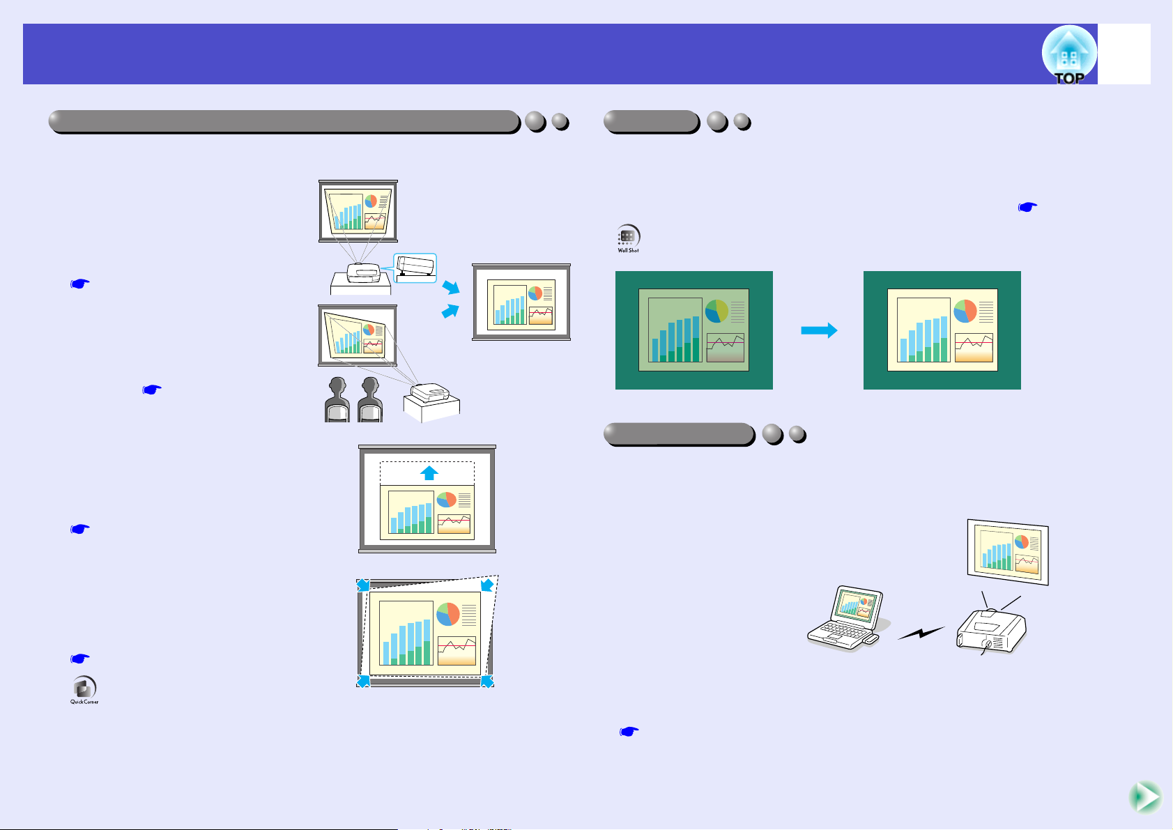
Position adjustment function for a variety of projection screens
Wall Shot
Network Support
Features of the Projector
Images can be projected regardless of the location.
• The keystone distortion that occurs
as a result of the projector being
tilted using the front adjustable
foot can be corrected.
(Automatic keystone correction
p.46)
• The keystone distortion that occurs
when projecting from the side of
the screen can also be corrected.
(Vertical correction and horizontal
correction p.47)
• If vertical keystone correction causes the
height of projected images to be too
short, the height of the projection area can
also be adjusted. (Height correction
p.48)
• The Quick Corner function can be used
to correct the four corners of the
projection area to make the images fit the
screen exactly.
p.49
1
Images can be projected in places without a screen with no loss of original
colour.
This automatically adjusts image colours to their natural colours even when
projecting onto surfaces such as blackboards and partitions. p.51
When something goes wrong with the projector, such as lamp blowing
during projection, the projector can notify you of the error via e-mail.
In addition, if you are
using EMP-7950, EasyMP
allows you to;
• Make easy network
connection with a
computer via a wireless
LAN.
• Project a computer's
image over a network.
For instructions on how to use EasyMP, refer to EasyMP Network Setup
Guide and EasyMP Operation Guide.
Page 3

User’s Guide
Large-volume USB Storage is Available to Use
Features of the Projector
(EMP-7950 only)
As well as a USB-compatible digital camera, you can use a USB-compatible
hard disk and a USB-compatible memory device. This allows you to use
large presentation files. p.32, "Showing the Presentation (Using the
CardPlayer)" in the EasyMP Operation Guide
Versatile interface
Wide range of devices can be connected to the projector.
It accepts both digital and analogue signals from a computer. And it offers
various types of connectors that meet your devices (such as component
videog) and your cables. p.20
2
Page 4

User’s Guide
Contents
Features of the Projector....................................................... 1
Before Using the Projector
Part Names and Functions.................................................... 6
Front/Top/Side ............................................................................ 6
Base............................................................................................. 7
Rear ............................................................................................. 7
Control Panel .............................................................................. 8
Remote Control........................................................................... 9
Input/Output Ports (EMP-7900) ............................................... 10
Input/Output Ports (EMP-7950) ............................................... 11
Before Using the Remote Control ....................................... 12
Inserting the Batteries ............................................................... 12
Using the Remote Control and Remote Operating Range ........ 13
Installation ........................................................................... 15
Setting Up the Projector............................................................ 15
Screen Size and Projection Distance......................................... 16
Inserting and Removing Cards (EMP-7950 only)................ 17
Installation................................................................................. 17
Removal .................................................................................... 18
Access Lamp Statuses............................................................... 19
Connecting to a Computer .................................................. 20
Eligible Computers ................................................................... 20
Projecting Images from the Computer ...................................... 21
Using the Remote Control to Operate the Mouse Pointer
(Wireless Mouse Function) ..................................................... 23
Connecting an External Monitor............................................... 25
3
Connecting to a Video Source .............................................26
Projecting Composite Video Images......................................... 26
Projecting S-Video Images........................................................ 27
Projecting Component Video Images........................................ 27
Projecting RGB Video Images.................................................. 28
Playing Sound from the Video Equipment ...........................29
Playing Sound from External Speakers ...............................31
Connecting USB Devices (Digital Camera, Hard Disk
Drive or Memory Devices) (EMP-7950 only)........................32
Connecting USB Devices.......................................................... 32
Disconnecting a USB Device from the Projector...................... 33
Basic Operations
Turning the Projector On ......................................................35
Connecting the Power Cable ..................................................... 35
Turning the Power On and Projecting Images .......................... 36
Selecting an Image Source While Viewing Projected Images
(Preview Function)................................................................... 38
Turning the Projector Off ......................................................40
Adjusting the Screen Image .................................................42
Adjusting the Image Size (Zoom Function) .............................. 42
Focusing the Screen Images (Focus Adjustment) ..................... 42
Adjusting the Image Angle ....................................................... 43
Manually Correcting Keystone Distortion ................................ 45
Adjusting the Image Quality .................................................51
Projecting Easy-to-see Images Without a Screen (Wall Shot) ..51
Adjusting Computer Images...................................................... 53
Selecting the Projection Quality (Colour Mode Selection)....... 56
Adjusting the Volume ...........................................................57
Page 5

User’s Guide
Contents
Preventing theft (Password Protect) .................................... 58
When Password Protect is enabled ........................................... 58
Setting Password Protect........................................................... 60
Advanced Operations
Functions for Enhancing Projection..................................... 63
A/V Mute Function ................................................................... 63
Freeze Function......................................................................... 64
E-Zoom Function ...................................................................... 64
P in P (Picture in Picture) Function .......................................... 65
Effect Function.......................................................................... 67
Preset Function.......................................................................... 69
Changing the Resize/Aspect Ratio............................................ 71
Projector ID/Remote Control ID............................................... 74
Operation Button Lock Function .............................................. 76
Using the Configuration Menu Functions ............................ 77
List of Functions ....................................................................... 78
Using the Configuration Menus................................................ 96
Monitoring and Controlling Projectors via a Network
(for the EMP-7900).............................................................. 98
Available Network Functions for the EMP-7900...................... 98
Compatible Computers ............................................................. 99
Installing and Uninstalling the Projector Software ................... 99
Network Cable Connections ................................................... 101
Projector Connection Settings................................................. 101
Problem Reporting Using the Mail Notification Function...... 103
Centralised Control using EMP Monitor ............................ 108
4
Troubleshooting
Using the Help ...................................................................114
Problem Solving.................................................................116
Reading the Indicators............................................................. 116
When the Indicators Provide No Help .................................... 119
Appendices
Maintenance ......................................................................140
Cleaning .................................................................................. 140
Replacing Consumables .......................................................... 141
Saving a User's Logo .........................................................148
Optional Accessories and Consumables ...........................151
Glossary.............................................................................152
List of ESC/VP21 Commands ............................................156
Command List ......................................................................... 156
Communication Protocol......................................................... 156
Cable Layouts.......................................................................... 157
USB Connection Setup............................................................ 158
List of Supported Monitor Displays ....................................159
Specifications.....................................................................160
Appearance........................................................................162
Page 6

Before Using the Projector
This chapter describes the procedures for setting up the projector before use.
Part Names and Functions................................... 6
• Front/Top/Side.......................................................................6
• Base.........................................................................................7
• Rear ........................................................................................7
• Control Panel.........................................................................8
• Remote Control .....................................................................9
• Input/Output Ports (EMP-7900)........................................10
• Input/Output Ports (EMP-7950)........................................11
Before Using the Remote Control ..................... 12
• Inserting the Batteries ........................................................12
• Using the Remote Control and Remote
Operating Range ................................................................13
• Using the Remote Control.............................................................................13
• Remote Operating Range ..............................................................................14
Installation........................................................... 15
• Setting Up the Projector .....................................................15
• Screen Size and Projection Distance..................................16
Inserting and Removing Cards
(EMP-7950 only) .................................................. 17
• Installation ...........................................................................17
• Removal................................................................................18
• Access Lamp Statuses .........................................................19
• Card Slot Access Lamp Status ......................................................................19
• Wireless LAN Card Access Lamp Status......................................................19
Connecting to a Computer ................................. 20
• Eligible Computers............................................................. 20
• Projecting Images from the Computer............................. 21
• If the Monitor Port is a Mini D-Sub 15-pin Port (Example) ........................ 21
• If the Monitor Port is a Digital RGB Port..................................................... 22
• Using the Remote Control to Operate the Mouse
Pointer (Wireless Mouse Function) .................................. 23
• Connecting an External Monitor ...................................... 25
Connecting to a Video Source ........................... 26
• Projecting Composite Video Images ................................. 26
• Projecting S-Video Images................................................. 27
• Projecting Component Video Images ............................... 27
• Projecting RGB Video Images........................................... 28
• If the RGB Output Port is a Mini D-Sub 15-pin Port (Example) ................. 28
Playing Sound from the Video Equipment........ 29
Playing Sound from External Speakers ............ 31
Connecting USB Devices (Digital Camera, Hard
Disk Drive or Memory Devices)
(EMP-7950 only) .................................................. 32
• Connecting USB Devices.................................................... 32
• Disconnecting a USB Device from the Projector ............. 33
Page 7
User’s Guide
••••
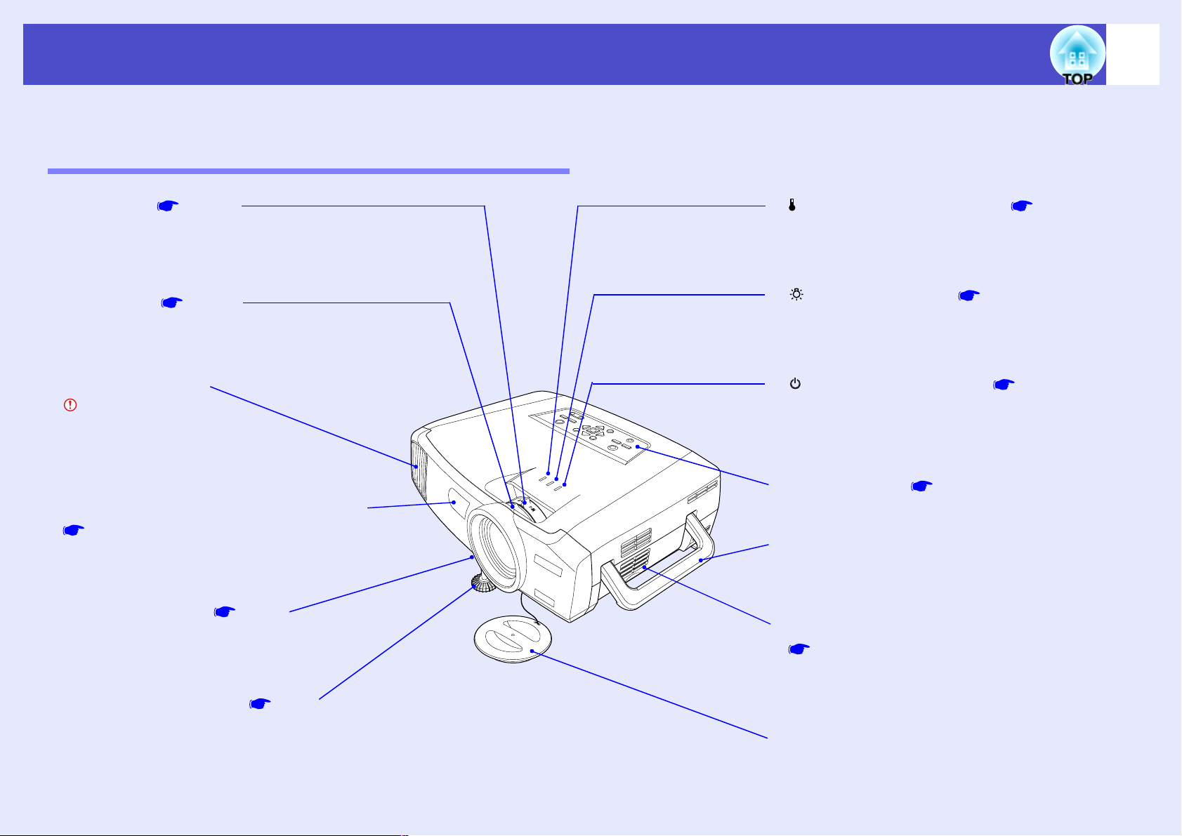
Front adjustable foot p.44
Extend and retract to adjust the projection
angle when the projector is placed on a surface
such as a shelf.
••••
Air filter (Air intake vent)
p.140, p.146
Prevents dust and other foreign particles from being
drawn into the projector. Clean the air filters
periodically.
••••
Handle
Use this handle when lifting and transporting the
projector.
••••
(Operation) indicator p.116
Flashes or lights in different colours to indicate the
operating status of the projector.
••••
(Lamp) indicator p.116
Flashes or lights in different colours to indicate
problems with the projection lamp.
••••
(Temperature) indicator p.116
Flashes or lights in different colours to indicate
problems with the internal temperature of the
projector.
••••
Foot adjust lever p.44
Pull out the foot adjust lever to extend and
retract the front foot.
••••
Control panel p.8
••••
Remote control light-receiving area
p.13
Receives signals from the remote control.
••••
Air exhaust vent
Do not touch during or
immediately after
projection, as it can
become hot.
••••
Lens cover
Attach when not using the projector in order to
prevent the lens from becoming dirty or damaged.
••••
Zoom ring p.42
Adjusts the image size.
••••
Focus ring p.42
Adjusts the image focus.
Part Names and Functions
The illustration below shows the projector with a standard lens fitted.
Front/Top/Side
6
Page 8
User’s Guide
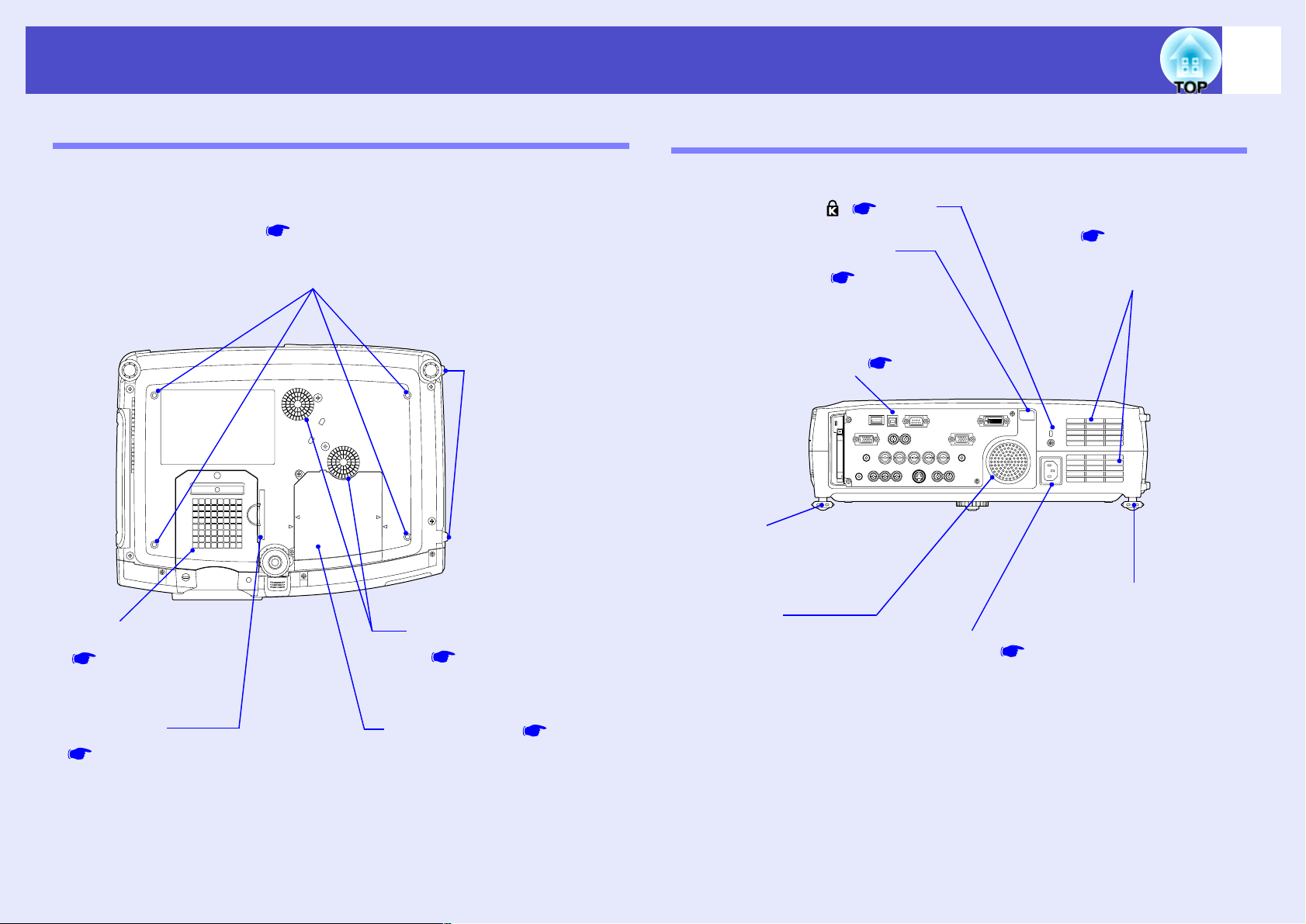
••••
Suspension bracket fixing points
(4 points) p.15, p.151
Connect an optional ceiling mount here when
suspending the projector from the ceiling.
••••
Air filter
p.140, p.146
Prevent dust and other
foreign particles from
being drawn into the
projector. Clean the air
filters periodically.
••••
Lamp cover p.142
Open this cover when
replacing the lamp inside the
projector.
••••
Air intake vent
p.140
Clean the air intake vent
periodically.
••••
Air intake vents
p.140
Clean the air intake vent
periodically.
••••
Feet for storage
Used when standing
the projector
vertically for
storage.
••••
Remote control lightreceiving area p.13
Receives signals from the remote
control.
••••
Power inlet p.35
Connect the power cable here.
••••
Input/output ports p.10
••••
Speaker
••••
Security lock ( ) p.154
••••
Rear adjustable foot
••••
Rear adjustable foot
••••
Air intake vents
p.140
Clean the air intake vent
periodically.
Part Names and Functions
Base
7
Rear
Page 9
User’s Guide
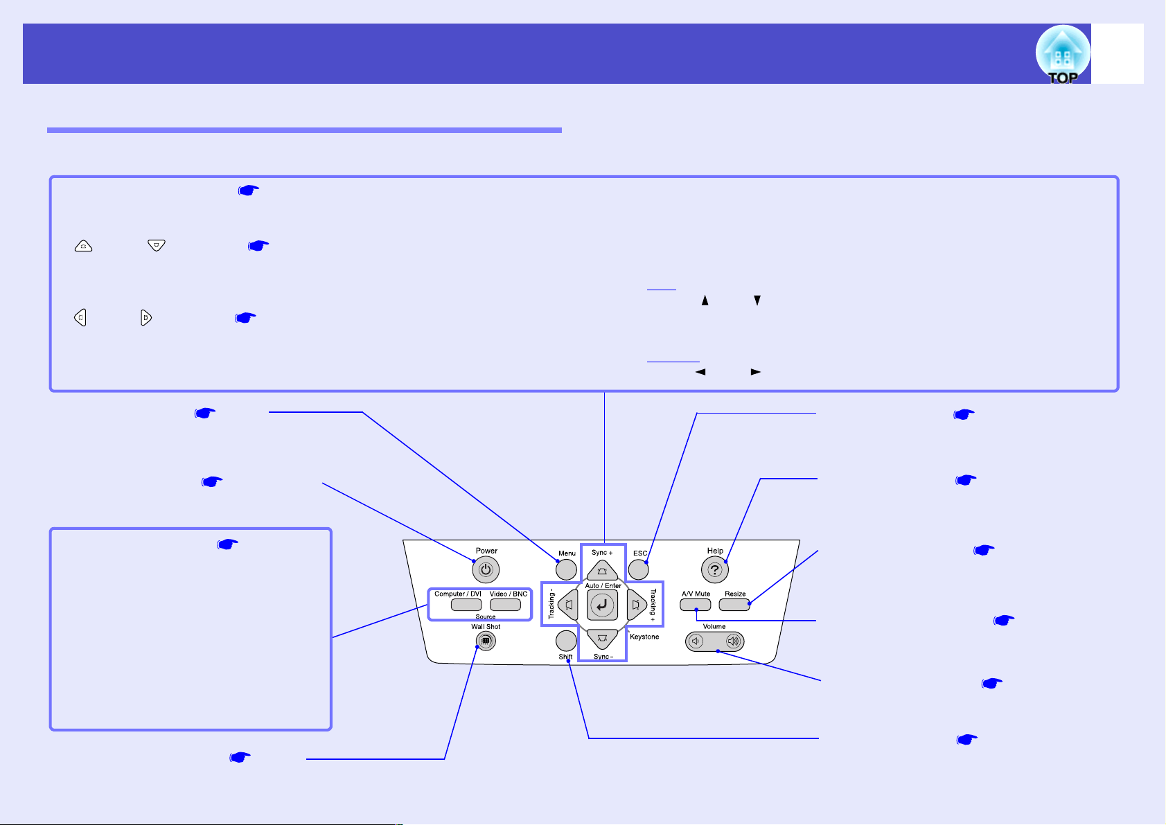
••••
[Auto/Enter] button p.53, p.96, p.114
Operates in the same way as the [Auto] button on the remote control.
When pressed while a configuration menu or help menu is being displayed, it operates in the same way as the [Enter] button on the remote control.
••••
[ ] and [ ] buttons p.47, p.49, p.55, p.96, p.114
Use these buttons for vertical keystone correction and correction using Quick Corner.
If you press one of these buttons while holding down the [Shift] button, you can adjust the sync
g of computer images.
When pressed while a configuration menu or help menu is being displayed, these buttons function as [ ] and [ ] (up and down) buttons for selecting items in the menu.
••••
[ ] and [ ] buttons p.47, p.49, p.54, p.97, p.114
Use these buttons for horizontal keystone correction and correction using Quick Corner.
If you press one of these buttons while holding down the [Shift] button, you can adjust the tracking
g of computer images.
When pressed while a configuration menu or help menu is being displayed, these buttons function as [ ] and [ ] (left and right) buttons for adjusting the setting value.
••••
[Menu] button p.96
••••
[Shift] button p.54, p.55, p.73
This button is used when adjusting the sync
and tracking and when using the resize
function.
••••
[Resize] button p.71
••••
[Volume] button p.57
••••
[A/V Mute] button p.63
••••
[ESC] button p.97, p.114
••••
[Power] button p.36, p.40
••••
[Wall Shot] button p.51
••••
[Source] buttons p.37
[Computer/DVI] button:
Switches the input source between the
[Computer] port, the [DVI] port and
EasyMP (EMP-7950 only) in that order
each time the button is pressed.
[Video/BNC] button:
Switches the input source between the
[S-Video] port, [Video] port and the
[BNC] ports in that order each time the
button is pressed.
••••
[Help] button p.114
Part Names and Functions
Control Panel
Buttons with no description are the same as the remote control buttons. Refer to the remote control descriptions for details.
8
Page 10
User’s Guide
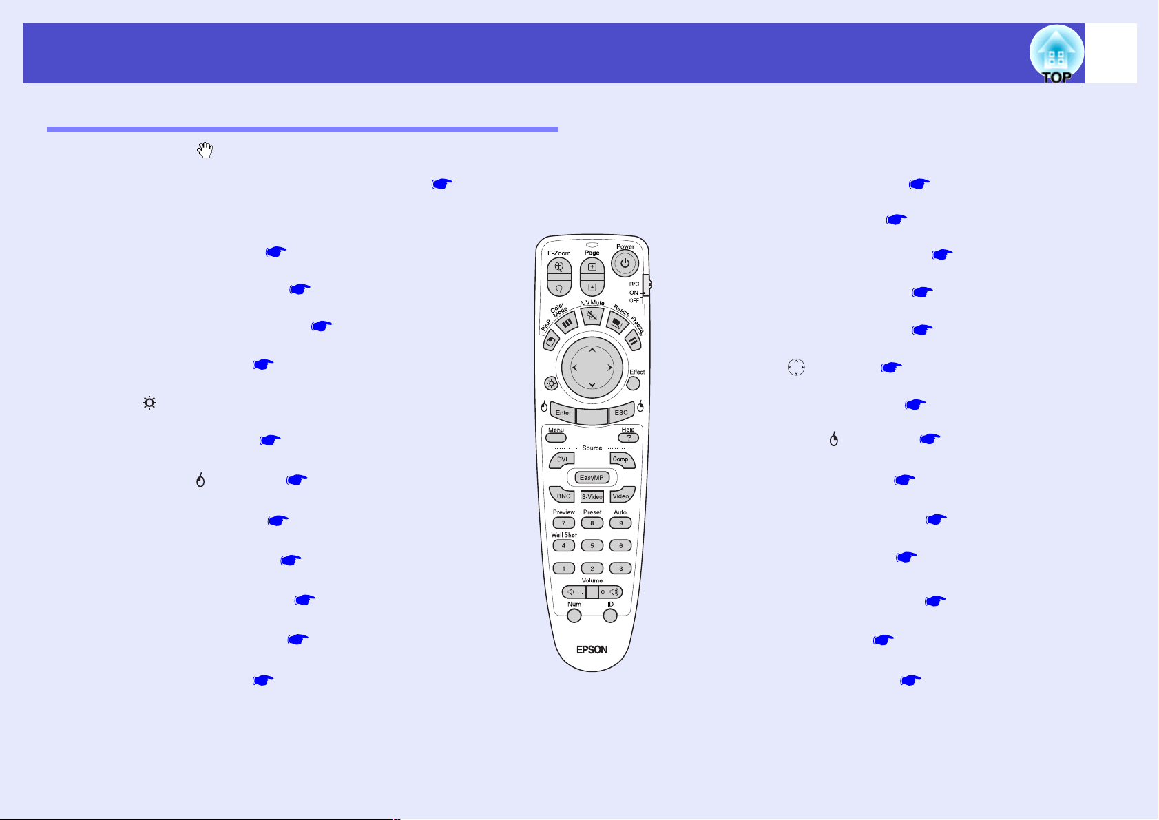
••••
Remote control light-emitting area p.14
••••
Indicator
••••
[Page] buttons p.23
••••
[E-Zoom] buttons p.64
••••
[Power] button p.36, p.40
••••
[R/C] switch p.13
••••
[ ] button p.24, p.96, p.114
••••
[Enter( )] button p.24, p.96, p.114
••••
[Menu] button p.96
••••
[Effect] button p.67
••••
[ ] (illumination) button
••••
[Volume] buttons p.57
••••
[ESC( )] button p.24, p.97, p.114
••••
[Help] button p.114
••••
Numeric buttons p.75, p.102
••••
[ID] button p.75
••••
[Num] button p.58, p.102
••••
[Remote] port p.14, p.151
••••
[Preview] button p.38
••••
[Preset] button p.69
••••
[Auto] button p.53
••••
[Wall Shot] button p.51
••••
[Source] buttons p.37
••••
[PinP] button p.65
••••
[A/V Mute] button p.63
••••
[Resize] button p.71
••••
[Freeze] button p.64
••••
[Color Mode] button p.56
Part Names and Functions
Remote Control
If you position the over the button icon or button name, a description of that button will appear.
9
Page 11
User’s Guide
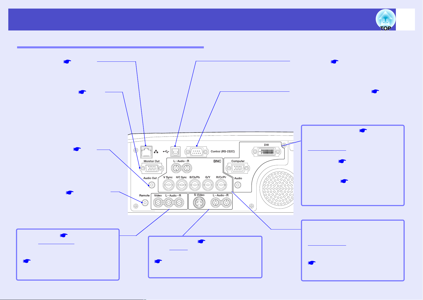
••••
[USB] port p.23, p.157
Connects the projector to a computer via the USB
cable when using the wireless mouse function.
••••
[Video] port p.26
Inputs composite video
g signals from a
video source.
••••
[Audio] ports (for [Video] port)
p.29
Input audio signals from the source that is
connected to the [Video] port.
••••
[Audio Out] port p.31
Outputs the audio signals from the
selected video source to external speakers.
••••
[Remote] port p.14, p.151
Connect the optional remote control cable
set to input signals from the remote control.
••••
[Monitor Out] port p.25
Outputs currently-projected analogue-RGB
signals from a computer to an external
monitor. It is not compatible with digitalRGB signals from computers and signals
from video equipment.
••••
[Computer] port p.21, p.28
Input analogue RGB video signals from a
computer and RGB video signals and
component video
g signals from other
video sources.
••••
[DVI] port p.22
Inputs digital RGB computer video signals.
••••
[Audio] port (for [Computer],
[DVI] port) p.29
Inputs audio signals from the equipment
connected to the [Computer] port or the
[DVI] port.
••••
[BNC] ports
Inputs analogue-RGB signals from a
computer and RGB-video signals and
component video
g signals from video
equipment.
••••
[Audio] ports (for [BNC] port)
p.29
Input audio signals from the source that is
connected to the [BNC] ports.
••••
[Control (RS-232C)] port p.157
Connects the projector to a computer using
an RS-232C cable. This port is for control
use and should not be used by the customer.
••••
[S-Video] port p.27
Inputs S-Video
g signals from a video source.
••••
[Audio] ports (for [S-Video] port)
p.29
Input audio signals from the source that is
connected to the [S-Video] port.
••••
Network port p.101
Use to connect the projector to a network.
Part Names and Functions
Input/Output Ports (EMP-7900)
10
Page 12
User’s Guide
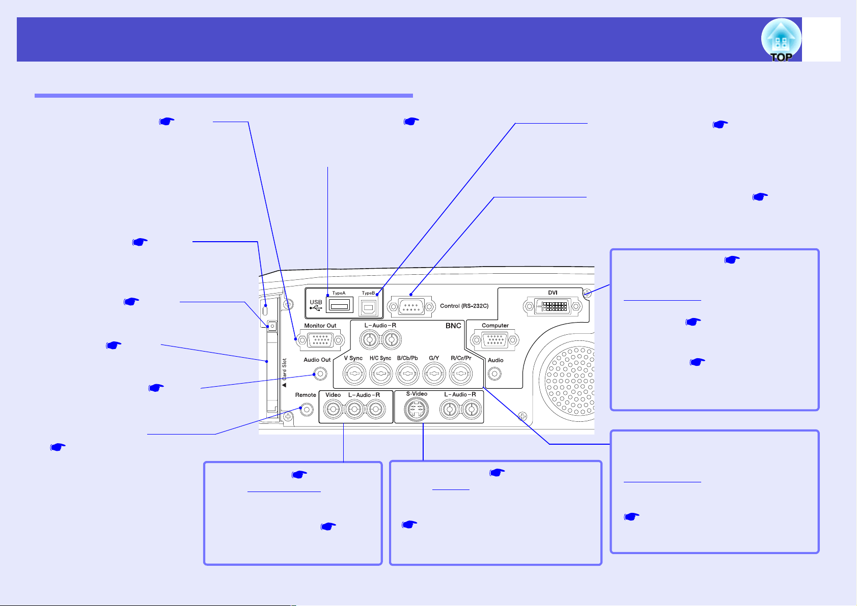
••••
[USB TypeB] port p.23 , p.157
When the projector is connected to a computer
with a computer cable, use this port to connect a
USB cable to the computer to use the wireless
mouse function.
••••
[Video] port p.26
Inputs composite video
g signals
from a video source.
••••
[Audio] ports
(for [Video] port) p.29
Input audio signals from the source
that is connected to the [Video] port.
••••
[Audio Out] port p.31
Outputs the audio signals from the
selected video source to external speakers.
••••
[Remote] port
p.14, p.151
Connect the optional remote
control cable set to input signals
from the remote control.
••••
[Monitor Out] port p.25
Outputs analogue-RGB signals from a
computer connected to the projector by a
computer cable, to an external monitor. It is
not compatible with digital-RGB signals
from computers, video images and EasyMP
images.
••••
[Computer] port p.22
Input analogue RGB video signals from a
computer and RGB video signals and
component video
g signals from other
video sources.
••••
[DVI] port p.22
Inputs digital RGB computer video signals.
••••
[Audio] port (for [Computer],
[DVI] port) p.29
Inputs audio signals from the equipment
connected to the [Computer] port or the
[DVI] port.
••••
[BNC] ports
Inputs analogue-RGB signals from a
computer and RGB-video signals and
component video
g signals from video
equipment.
••••
[Audio] ports (for [BNC] port)
p.29
Input audio signals from the source that is
connected to the [BNC] ports.
••••
[Control (RS-232C)] port p.157
Connects the projector to a computer using
an RS-232C cable. This port is for control
use and should not be used by the customer.
••••
[S-Video] port p.27
Inputs S-Video
g signals from a video
source.
••••
[Audio] ports (for [S-Video] port)
p.29
Input audio signals from the source that is
connected to the [S-Video] port.
••••
[USB TypeA] port p.17
Connects a digital camera to the projector
when projecting digital camera image
files with EasyMP.
••••
Card Slot p.17
Insert a PC card into the
slot when using EasyMP.
••••
Access Lamp p.19
The access status of a memory card inserted
in the PC card slot is indicated by coloured
lights that may be on or off.
••••
Eject button p.18
Press this button to eject a PC card when it
has been inserted into the card slot.
Part Names and Functions
Input/Output Ports (EMP-7950)
11
Page 13
User’s Guide
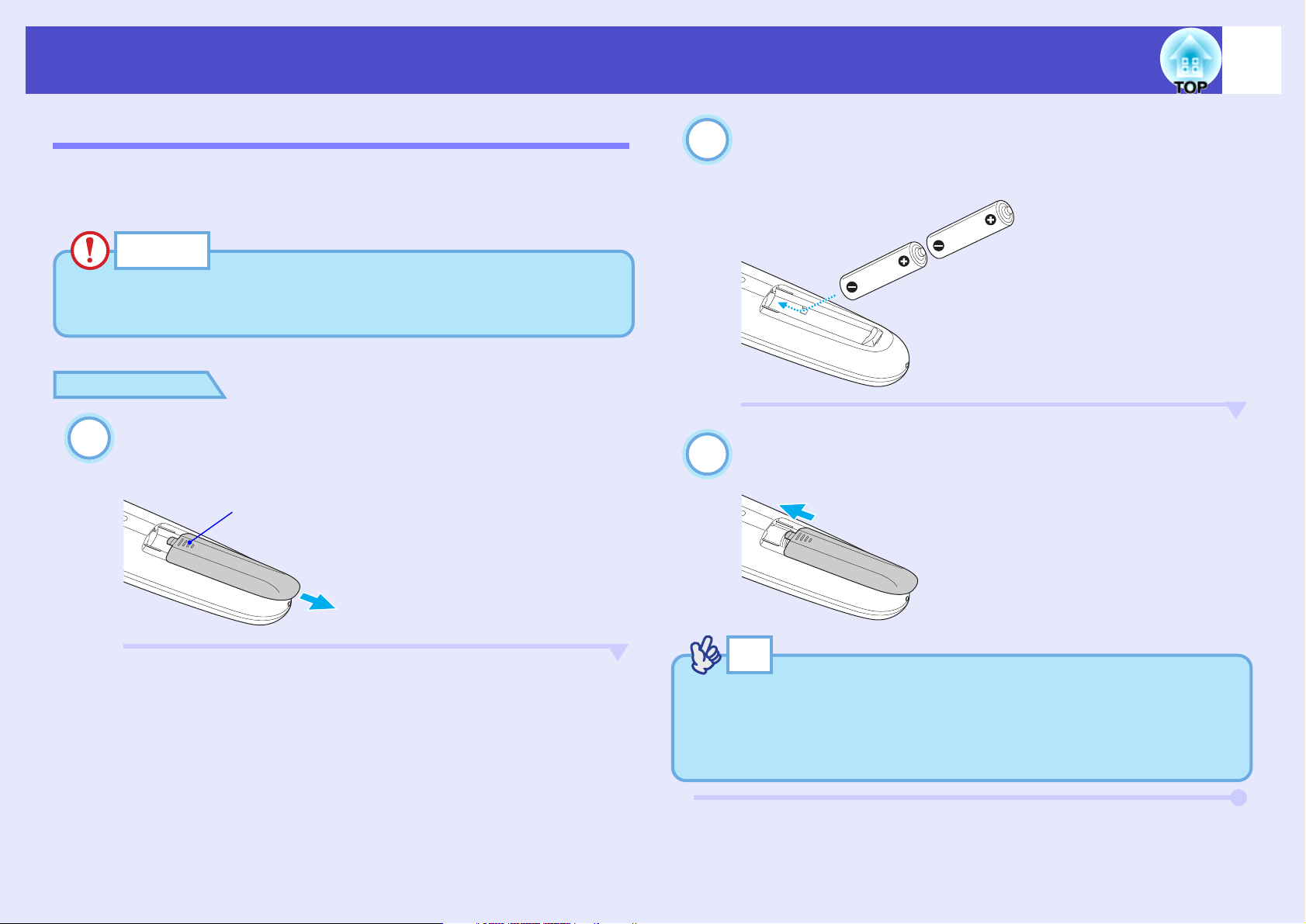
CAUTION
Be sure to read the Safety Instructions/World-Wide Warranty Terms
before handling the batteries.
1
Rib
2
3
TIP
If delays in the responsiveness of the remote control occur or if it does
not operate after it has been used for some time, it probably means
that the batteries are becoming flat. If this happens, replace the
batteries with two new AA alkali batteries.
Before Using the Remote Control
Inserting the Batteries
The batteries are not already inserted into the remote control at the time the
projector is purchased. You will need to insert the batteries that are
provided with the projector before the remote control can be used.
PROCEDURE
Remove the battery cover.
While pushing down on the rib of the battery cover, slide the
battery cover in the direction of the arrow.
12
Insert the batteries.
Check the positions of the (+) and (–) marks inside the battery
holder to ensure that the batteries are inserted the correct way.
Replace the battery cover.
Slide the battery cover in until the tab clicks into place.
Page 14
User’s Guide
1
2
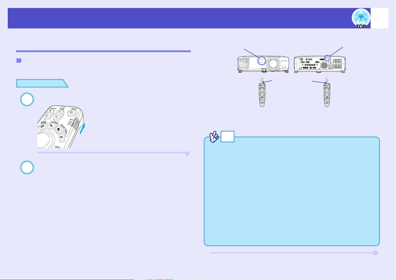
Remote control
light-receiving
area (front)
Remote control
light-receiving
area (rear)
Remote control
light-emitting area
Before Using the Remote Control
Using the Remote Control and Remote Operating Range
Using the Remote Control
The remote control is used in the following way.
PROCEDURE
Set the [R/C] switch of the remote control to "ON".
Point the remote control light-emitting area towards
one of the remote control light-receiving areas on the
projector and operate the remote control buttons.
13
TIP
• Do not allow sunlight or light from fluorescent lamps to shine
directly onto the projector's remote control light-receiving areas,
otherwise it may interfere with the reception of signals from the
remote control.
• When not using the remote control, set the [R/C] switch on the
remote control to "OFF". If you leave the [R/C] switch at "ON", it
will consume battery power.
• If a button on the remote control is pressed down for more than 1
minute while the [R/C] switch is at "ON", the signal for that button
operation will stop being transmitted (the remote control will change
to sleep mode). The purpose of this is to prevent the batteries from
being consumed due to something being placed on top of the remote
control.
When the button is released, normal remote control operation will
resume.
Page 15
User’s Guide
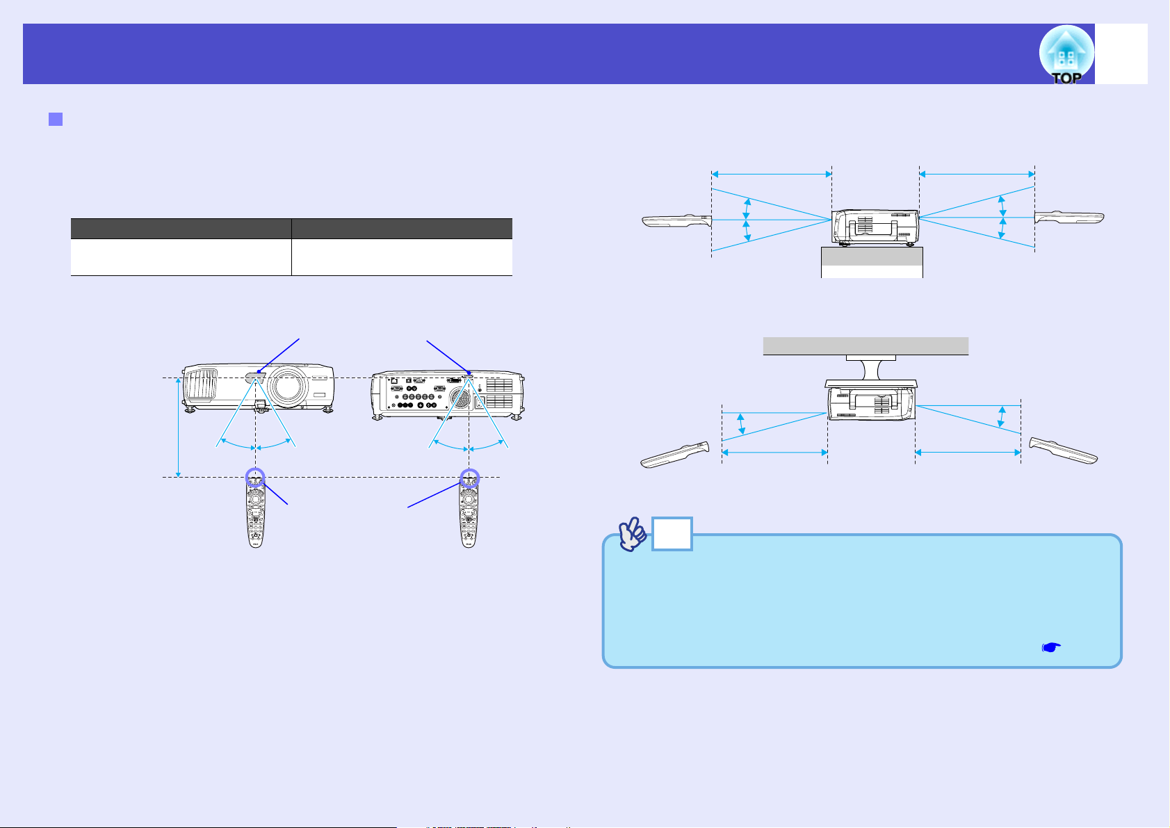
Remote control
light-receiving areas
Operating angle (horizontal)
Approx. 30°
Approx. 30°
Remote control
light-emitting area
Approx. 30°
Approx. 30°
Operating
distance approx.
10 m (30 ft.)
Operating angle (vertical)
Operating distance
approx. 10 m (30 ft.)
Approx. 15°
Approx. 15°
Approx. 15°
Approx. 15°
Operating distance
approx. 10 m (30 ft.)
When suspended from the ceiling
Operating distance
approx. 10 m (30 ft.)
Operating distance
approx. 10 m (30 ft.)
Approx. 15°
Approx. 15°
Before Using the Remote Control
Remote Operating Range
Use the remote control within the ranges indicated below. If the distance or
angle between the remote control and the remote control light-receiving
area is outside the normal operating range, the remote control may not
work.
Operating distance Operating angle
Approx. 10 m (30 ft.)
14
Approx. ±30° horizontally
Approx. ±15° vertically
TIP
If you would like to ensure that remote control operations work
properly from a distance, use the optional remote control cable set to
connect the [Remote] port of the remote control to the projector's
[Remote] port.
See "Appendices: Optional Accessories and Consumables" p.151
Page 16
User’s Guide
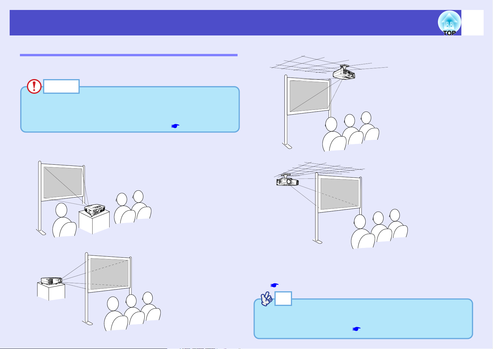
• Front projection
• Rear projection using a translucent screen
• Front/ceiling projection
• Rear/ceiling projection using a translucent screen
Installation
Setting Up the Projector
The projector supports the following four different projection methods,
allowing you to choose the best method for displaying your images.
CAUTION
• Before setting up the projector, be sure to first read the separate
Safety Instructions/World-Wide Warranty Terms.
• The projector has feet on its side for storage. Do not set up the
projector vertically with the feet for projection. p.7
15
* A special method of installation is required for suspending the projector
from the ceiling. Please contact your supplier if you would like to use
this installation method. The optional ceiling mount is required when
installing the projector on the ceiling.
p.151
TIP
When using rear/ceiling projection using a translucent screen, set the
"Ceiling" and "Rear Proj." commands in the "Advanced1" menu to
match the installation method. p.90
Page 17
User’s Guide
Screen
90º
Centre of lens
*
Projection distance
Installation
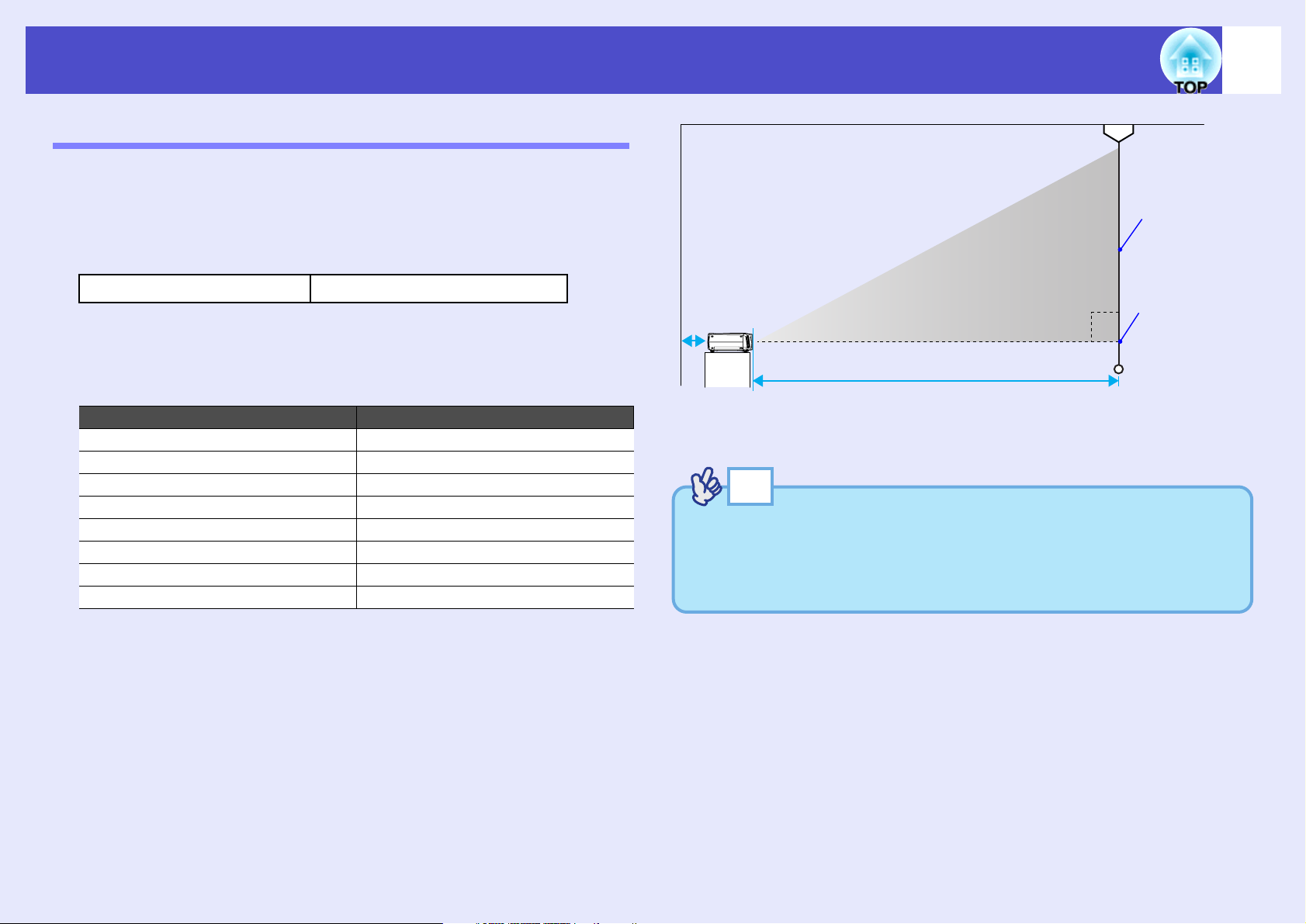
Screen Size and Projection Distance
The distance from the lens to the screen determines the actual image size.
The recommended distance and projection distance values given below are
for when the projector is fitted with a standard lens or an optional wide
zoom lens. If the projector has been fitted with an optional lens, refer to the
documentation provided with the lens.
Recommended distance
While referring to the following table, position the projector so that the
images are projected onto the screen at the optimum size. The values
should be used as a guide for setting up the projector. The actual values
will vary depending on projection conditions and the zoom setting.
4:3 screen size (cm (in.)) Projection distance (cm (ft.))
30" (61 × 46 (24.0 × 18.1)) 77−107 (2.5–3.5)
40" (81 × 61 (31.9 × 24.0)) 105−144 (3.5–4.7)
50" (100 × 76 (39.4 × 30.0)) 133−181 (4.4–6.0)
60" (120 × 90 (47.2 × 35.4)) 161−219 (5.3–7.2)
80" (160 × 120 (63.0 × 47.2)) 216−293 (7.1–9.6)
100" (200 × 150 (78.7 × 59.1)) 272−368 (8.9–12.1)
200" (410 × 300 (161.4 × 118.1)) 550−740 (18.0–24.3)
300" (610 × 460 (240.2 × 181.1)) 827−1113 (27.1–36.5)
77–1113 cm (2.5–36.5 ft.)
16
* When installing against a wall, leave a space of 20 cm (7.9 in.) or more
between the projector and the wall.
TIP
The standard lens or the optional wide zoom lens allows a zoom ratio
of up to about 1.35. The image size at the maximum zoom setting is
about 1.35 times bigger than the image size at the minimum zoom
setting.
Page 18
User’s Guide
Rear
Inserting and Removing Cards (EMP-7950 only)
You can use PC cards such as wireless LAN cards and memory cards with the
EMP-7950.
The EMP-7950 is supplied with wireless LAN card. When using other cards,
or inserting or removing a card in a PC card slot on a computer, refer to the
documentation included with the card.
TIP
The following PC cards can be inserted into the projector's card slot.
• Wireless LAN card (the card supplied with the EMP-7950)
• Memory card. See "Appendices: Specifications" p.161
Installation
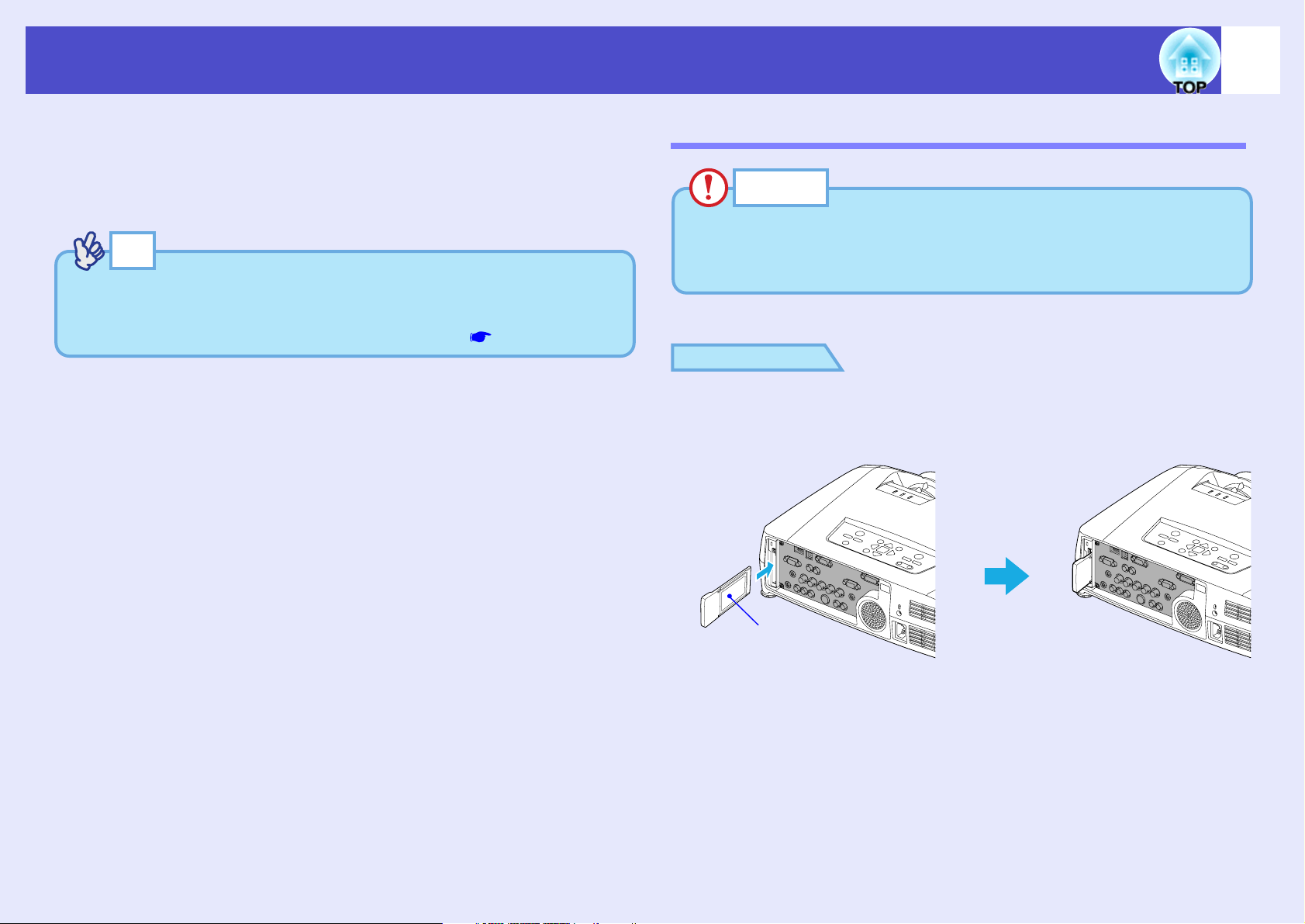
CAUTION
• Insert the PC card facing the right way. Installing the device back to
front or upside down may cause failure or damage.
• Be sure to remove the card before transporting the projector.
PROCEDURE
Insert the PC card into the slot so that it is facing to the
left.
Insert firmly into the slot until it is secure.
17
Page 19
User’s Guide
1
Eject button
Access lamp
2
Inserting and Removing Cards (EMP-7950 only)
Removal
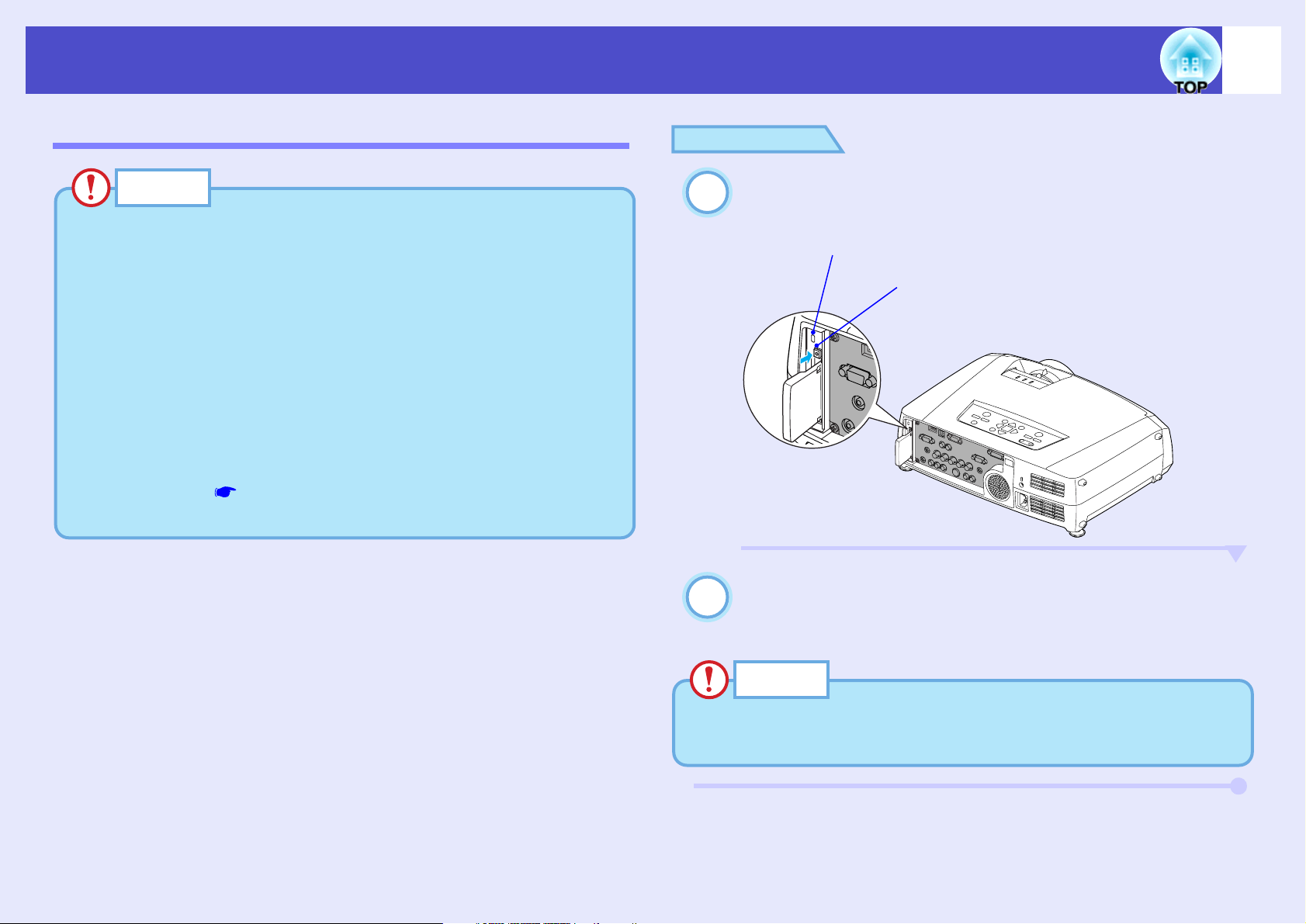
CAUTION
• Do not remove the wireless LAN card while the access lamp of the
wireless LAN card is flashing green, otherwise it may damage the
wireless LAN card.
• Do not remove a memory card while the access lamp of the
projector's card slot is flashing green, or while projecting a scenario.
Doing so may damage the memory card itself or data in the card.
• The PC card gets hot during and immediately after projector use.
Handle the card carefully when removing it from the card slot to
avoid personal injury or burns.
• When you wish to remove a memory card while using CardPlayer, be
sure to close CardPlayer before removal. CardPlayer may
malfunction if a memory card is removed without closing
CardPlayer first. "Closing CardPlayer" in the EasyMP
Operation Guide
18
PROCEDURE
Press the eject button to the right of the card slot.
The eject button will pop out.
Press the eject button again.
Enough of the PC card will be ejected so that you can grasp the
edge of the card and pull it straight out of the slot.
CAUTION
Be sure to press the eject button back in to prevent it from being
broken or damaged.
Page 20
User’s Guide
Inserting and Removing Cards (EMP-7950 only)
Access Lamp Statuses
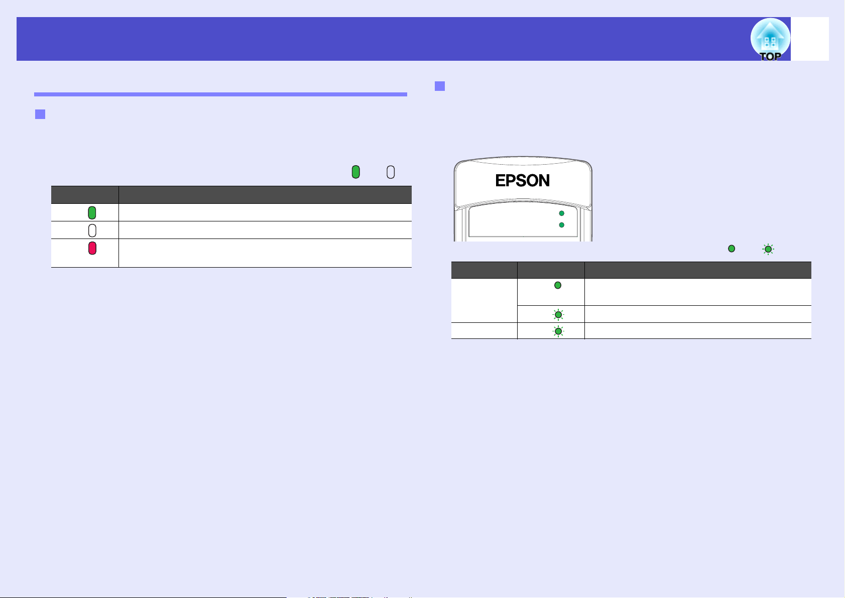
Card Slot Access Lamp Status
When a memory card has been inserted into the card slot of the projector,
you can check the access status for the memory card by noting whether the
access lamp is lit and what colour it is, as described below.
Lit Off
Status Access status
Green Data is being read from the memory card.
Off The memory card is in standby state.
Red An error occurred while data was being read from the memory
card.
Wireless LAN Card Access Lamp Status
The card slot access lamp does not light when a wireless LAN card has
been inserted into the projector.
You can check the network communication status by observing the status
of the wireless LAN access lamps as described below.
LINK
ACT
Lit flashing
Lamp Status Communication status
LINK Green The projector is connected to the network and
communication is possible.
Connection to a valid network is in progress.
Data is being transmitted or received.
ACT
Green
Green
19
Page 21
User’s Guide
Connecting to a Computer
CAUTION
When connecting the projector to a computer, be sure to check the
following.
• Turn the power off for both the projector and the computer before
connecting them. If the power for either device is on at the time of
connection, damage may result.
• Check the shapes of the cable connectors and the device ports before
making the connections. If you try to force a connector to fit a device
port with a different shape or number of terminals, a malfunction or
damage to the connector or port may result.
• Do not bind the power cable and the connecting cable together. If
the power cable and the connecting cable are bound together, image
interference or errors in operation may result.
Eligible Computers
20
• Condition 2: The display resolution and frequency of the computer
must be listed in the "List of Supported Monitor Displays".
See "Appendices: List of Supported Monitor Displays" p.159
Some computers allow you to change the output resolution, so if
necessary, change the resolution to one that matches a setting in the "List
of Supported Monitor Displays". Refer to the documentation provided
with the computer.
TIP
• You may need to purchase a commercially-available adapter
depending on the shape of the computer's port. Refer to the
documentation provided with the computer for further details.
• If the computer and projector are too far away from each other for
the accessory computer cable to reach, use the optional VGA-HD15
PC cable. See "Appendices: Optional Accessories and
Consumables" p.151
The projector cannot be connected to some types of computer, or
projection of images may not be possible even if actual connection is
possible. Make sure that the computer you intend to use satisfies the
conditions given below.
• Condition 1: The computer must have an image signal output port.
Check that the computer has a port such as an "RGB port", "monitor port"
or "CRT port" which can output image signals.
If the computer has a built-in monitor, or if using a laptop computer, it
may not be possible to connect the computer to the projector, or
alternatively you may need to purchase a separate external output port.
Refer to the documentation for your computer under a heading such as
"Connecting an external monitor" or similar for further details.
Page 22
User’s Guide
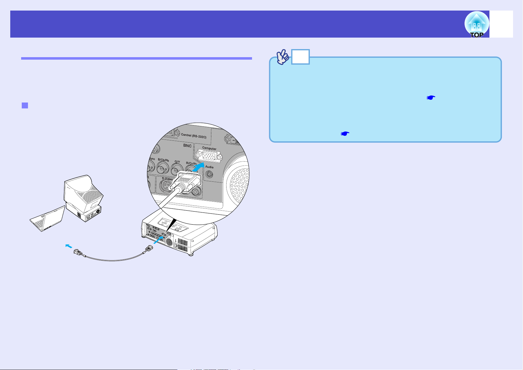
Computer cable
(accessory)
To monitor port
To [Computer] port (blue)
Connecting to a Computer
Projecting Images from the Computer
The shape and specifications of the computer's monitor port will determine
what type of cable should be used. Check the following to see which type
of port your computer has.
If the Monitor Port is a Mini D-Sub 15-pin Port (Example)
Use the accessory computer cable to make the connections.
21
TIP
• Image sources are auto-detected according to the input signals.
Depending on an output signal of a computer, the image may be
projected in unnatural colours. In such case, set the "Computer
Input" in the configuration menu to "RGB". p.86
• When connecting more than one device to the projector, use the
[Comp] button on the remote control, or the [Computer/DVI] button
on the projector's control panel to switch between devices after
starting projection. p.37
Page 23
User’s Guide
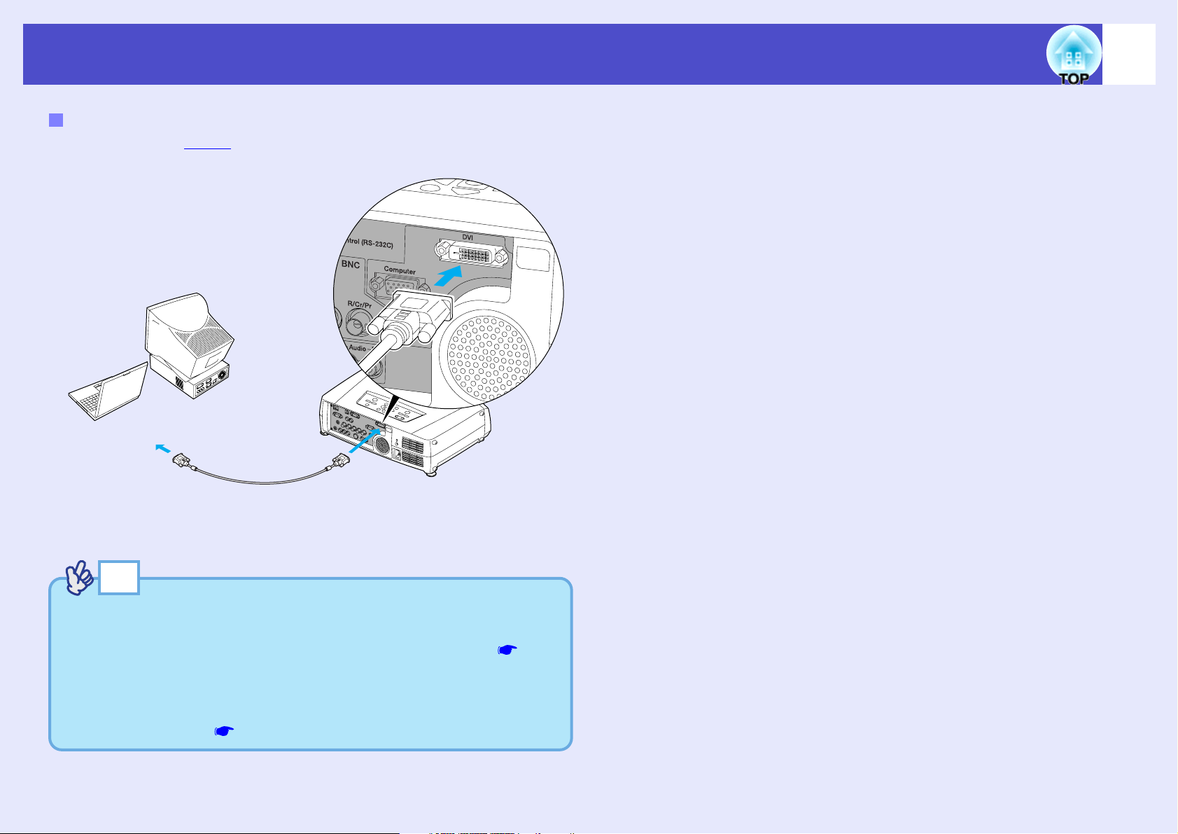
DVI-D/DVI-D digital video cable or
DVI-D/DFP digital video cable
(optional)
To monitor port
To [DVI] port
Connecting to a Computer
If the Monitor Port is a Digital RGB Port
Use the optional DVI-Dg/DVI-D digital video cable or DVI-D/DFP digital
video cable to make the connection.
22
TIP
• Use whichever optional DVI-D/DVI-D digital video cable or DVI-D/
DFP digital video cable matches the monitor port of the computer.
See "Appendices: Optional Accessories and Consumables" p.151
• When connecting more than one device to the projector, use the
[DVI] button on the remote control, or the [Computer/DVI] button
on the projector's control panel to switch between devices after
starting projection. p.37
Page 24
User’s Guide
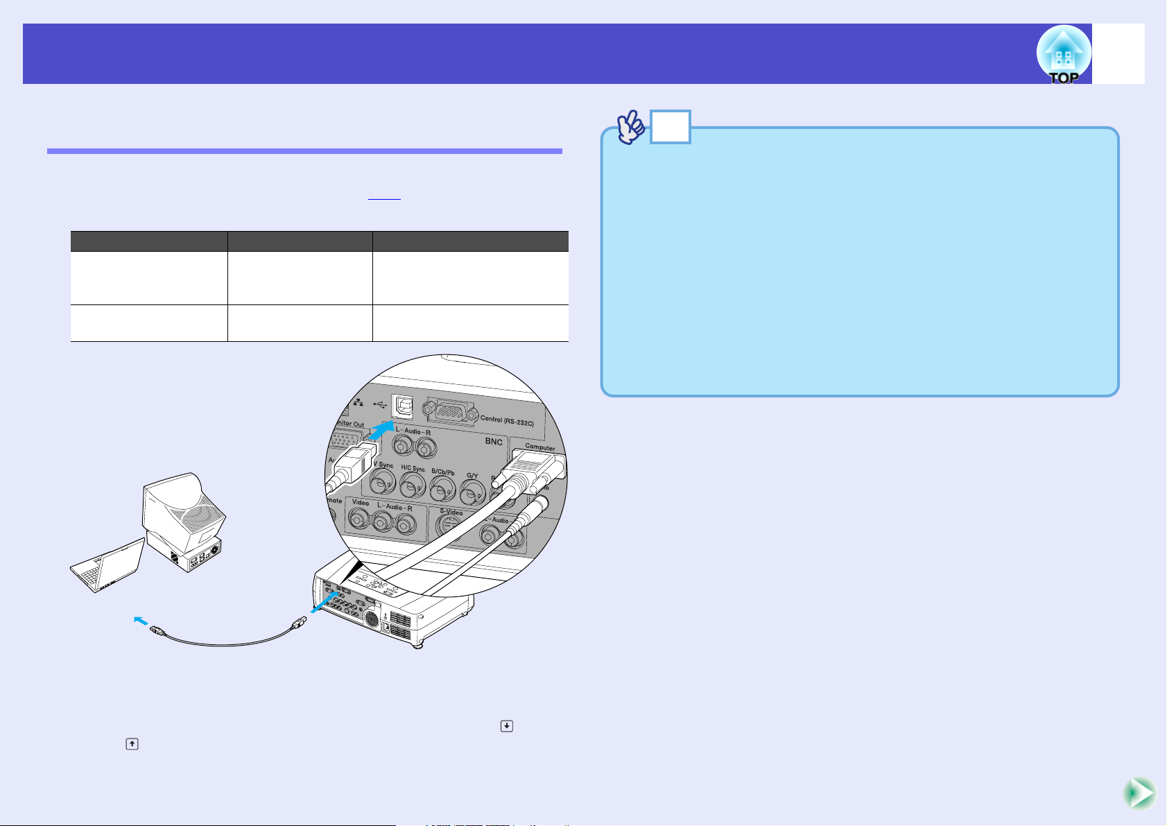
USB cable
(accessory)
To [USB] port
*For the EMP-7950
To [USB TypeB] port
To USB port
TIP
• The USB cable can only be connected to computers with a standard
USB interface. If using a computer which is running Windows, the
computer must have had a full version of Windows 98/2000/Me/XP
Home Edition/XP Professional installed. If the computer is running
a version of Windows 98/2000/Me/XP Home Edition/XP
Professional that has been upgraded from an earlier version of
Windows, correct operation cannot be guaranteed.
• It may not be possible to use the wireless mouse function under some
versions of both the Windows and Macintosh operating systems.
• Some computer settings may have to be changed in order for the
mouse function to be used. Consult the documentation for the
computer for further details.
Connecting to a Computer
Using the Remote Control to Operate the Mouse Pointer (Wireless Mouse Function)
You can use the remote control as a wireless mouse to control the mouse
pointer on the screen by using the accessory USBg cable to connect the
USB port of the computer to the [USB] port at the rear of the projector.
Computer Mouse used Applicable cable
Windows 98/2000/Me/
XP Home Edition/
XP Professional
Macintosh
(OS 8.6–9.2/10.0–10.3)
USB mouse USB cable (accessory)
USB mouse USB cable (accessory)
23
* When using the remote control as a wireless mouse, the [Page ] and
[Page ] buttons on the remote control can be used to scroll back and
forth through slides when projecting a PowerPoint presentation.
Page 25
User’s Guide
TIP
• If the mouse button settings have been reversed at the computer, the
operation of the remote control buttons will also be reversed.
• The wireless mouse function of the remote control cannot be used
while the following functions are being used.
· While a configuration menu is being displayed
· While a help menu is being displayed
· While the Effect function is being used
· While a sub-screen has been set using the P in P function
· While the E-Zoom function is being used
· While a Quick Corner setting has been made
· While a window is being displayed in real mode using the resize
function
· While the Preview function is being used
· While a user's logo is being captured
· While Wall Shot is enabled
· While Password Protect is being set
Connecting to a Computer
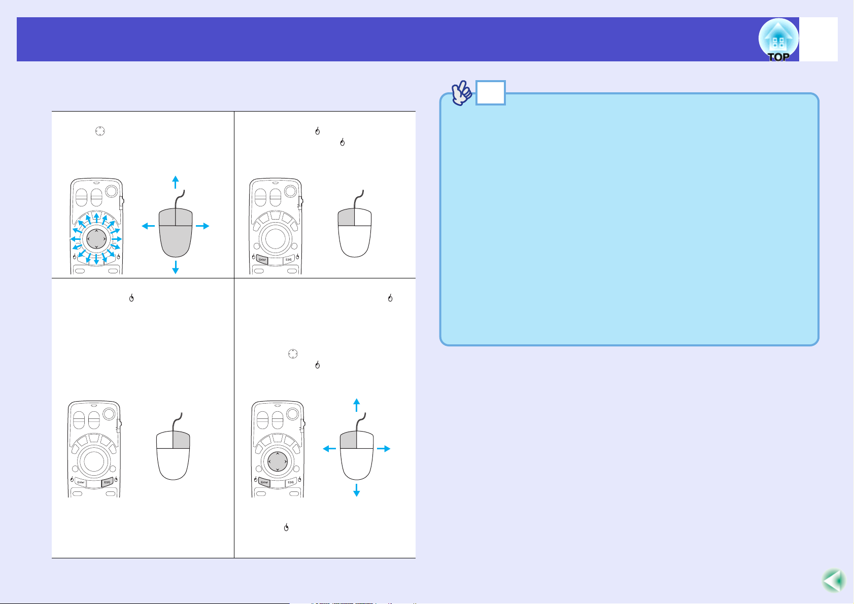
Once the connection has been made, the mouse pointer can be operated as
follows.
Moving the mouse pointer
Tilt the [ ] button on the remote
control to move the mouse pointer in
the direction of tilt.
Right click
Press the [ESC ( )] button.
Left click
Press the [Enter ( )] button.
If you press the [Enter ( )] button twice
in rapid succession, it has the effect of
a double-click.
Drag and drop
When you hold down the [Enter ( )]
button for approximately 1.5 seconds,
the button will light and drag and drop
mode will be enabled. In this mode,
you can carry out drag operations by
tilting the [ ] button.
Press the [Enter ( )] button at the
desired position to drop the items being
dragged.
Drag and drop mode can also be
enabled in the same way by pressing
the [ESC ( )] button for approximately
1.5 seconds. This operation allows
right click dragging and dropping.
24
Page 26
User’s Guide
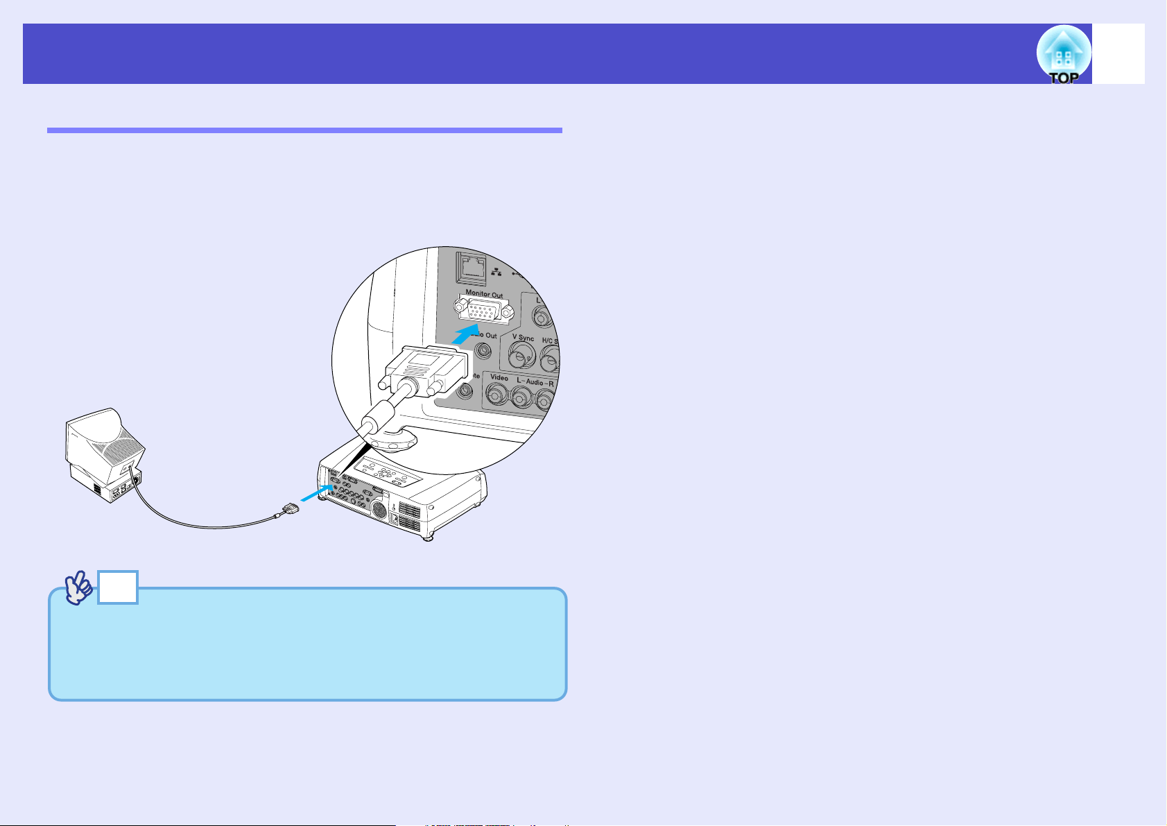
Cable provided with monitor
To [Monitor Out] port (black)
Monitor port
TIP
• Digital RGB images from a computer and video images cannot be
output to an external monitor.
• The setting gauge for keystone correction and the configuration
menus and help menus are not output to the external monitor.
Connecting to a Computer
Connecting an External Monitor
When analogue RGB signals from a computer are being projected, you can
connect an external monitor to the projector in order to view the images on
the external monitor at times such as when giving presentations.
Connect the external monitor using the cable that is provided with the
monitor.
25
Page 27
User’s Guide
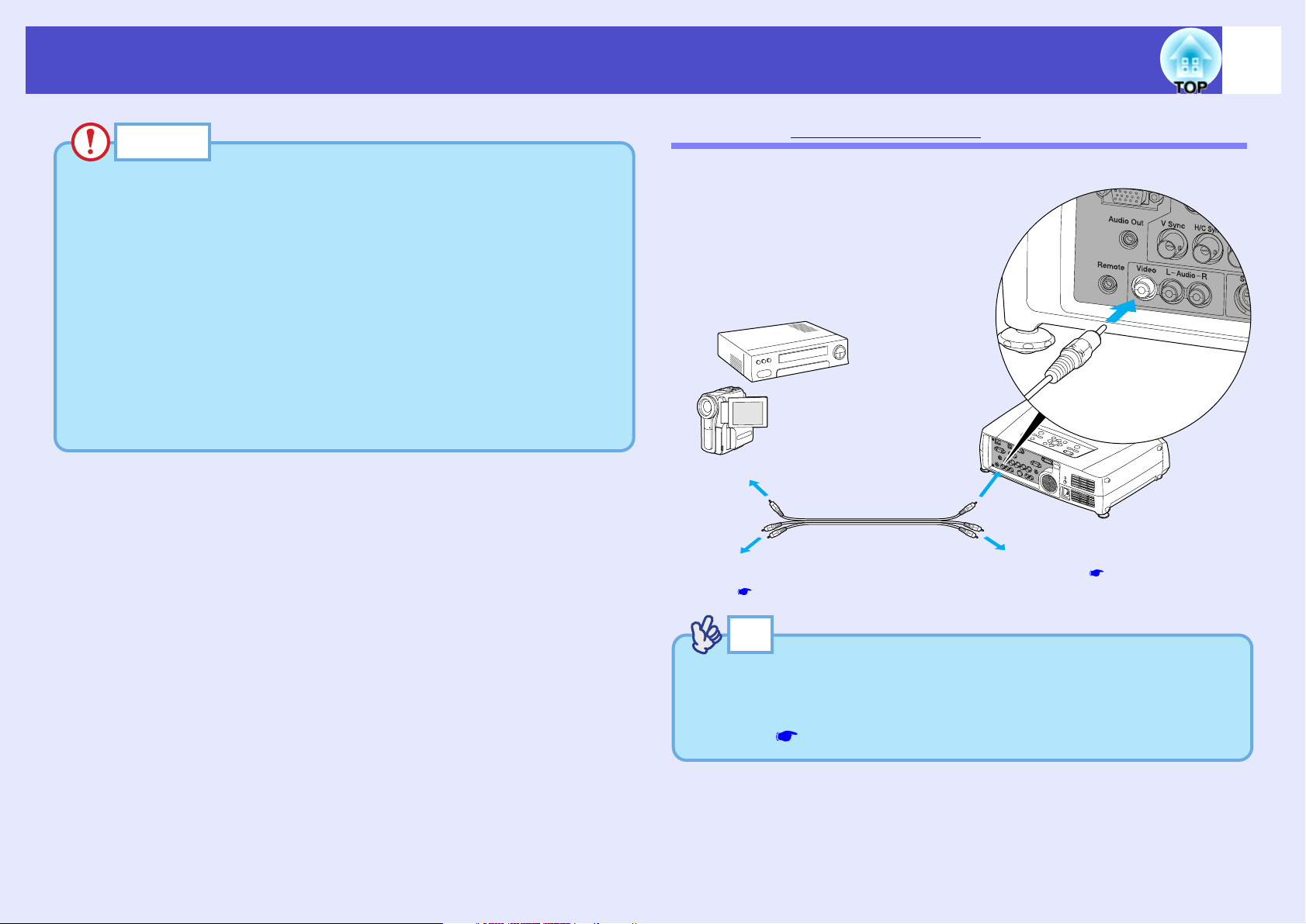
To video output port (yellow)
To [Video] port (yellow)
To audio output
ports p.29
A/V cable
(commercially-available)
To [Audio] port p.29
TIP
When connecting more than one device to the projector, use the
[Video] button on the remote control, or the [Video/BNC] button on
the projector's control panel to switch between devices after starting
projection. p.37
Connecting to a Video Source
CAUTION
When connecting the projector to other video sources, take the
following precautions.
• Turn the power off for both the projector and the video source before
connecting them. If the power for either device is on at the time of
connection, damage may result.
• Check the shapes of the cable connectors and the device ports before
making the connections. If you try to force a connector to fit a device
port with a different shape or number of terminals, damage to the
connector or port may result.
• Do not bind the power cable and the connecting cable together. If
the power cable and the connecting cable are bound together, image
interference or errors in operation may result.
26
Projecting Composite Videog Images
Use a commercially- available A/V cable to make the connection.
Page 28
User’s Guide
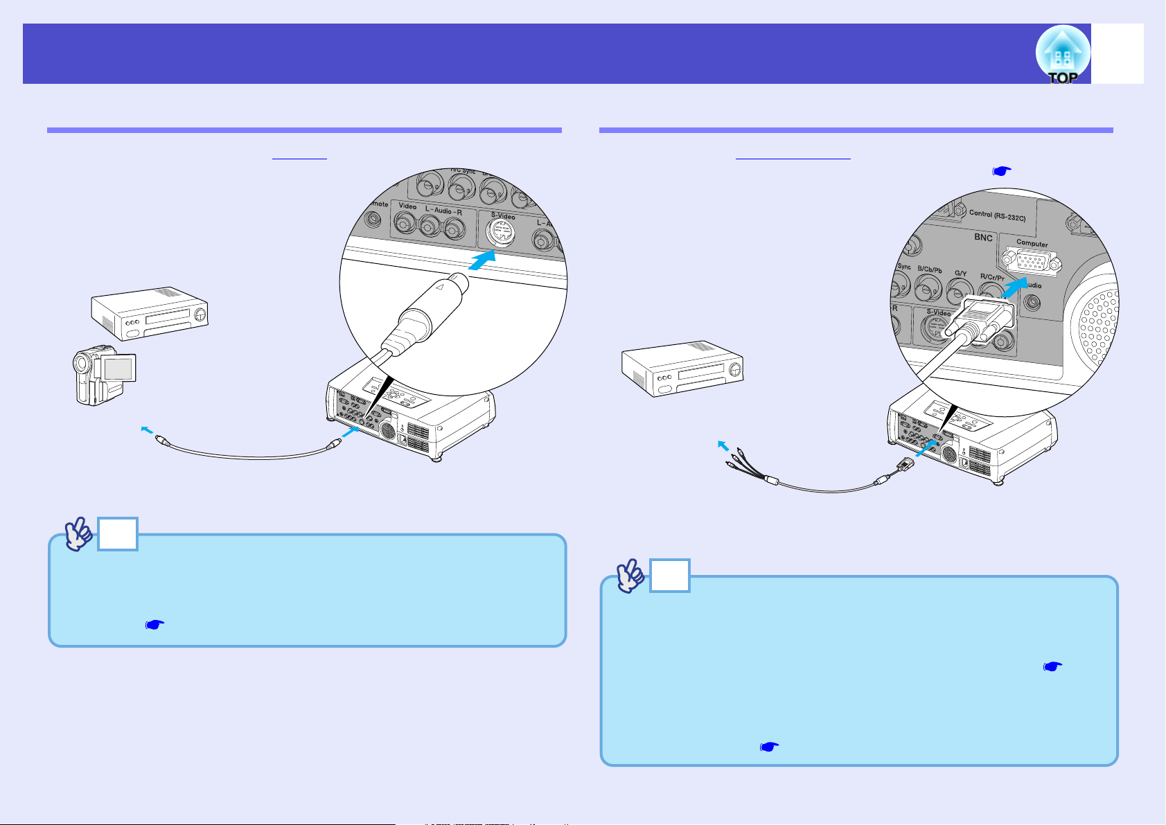
S-Video cable
(commercially-available)
To [S-Video] port
To S-Video output port
TIP
When connecting more than one device to the projector, use the [SVideo] button on the remote control, or the [Video/BNC] button on the
projector's control panel to switch between devices after starting
projection. p.37
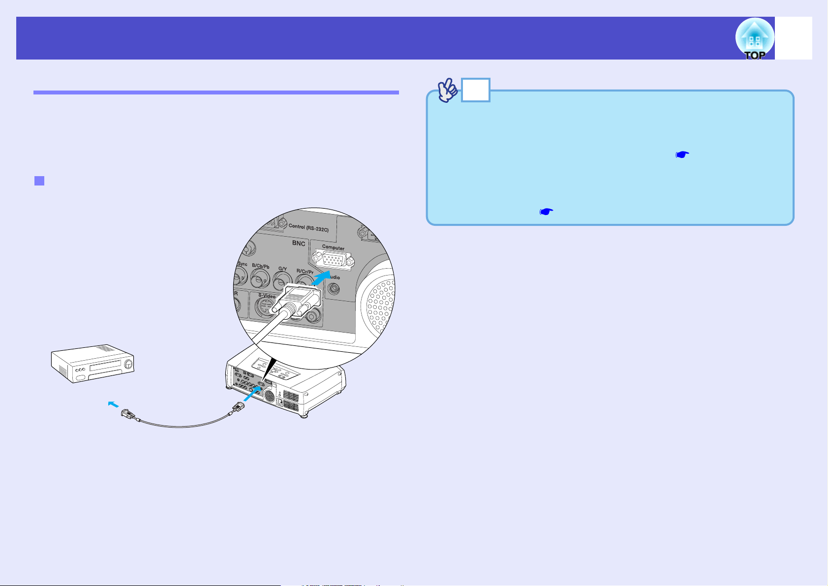
Component video cable
(optional)
To component
video output ports
To [Computer] port
TIP
• Image sources are auto-detected according to the input signals.
Depending on an output signal of a computer, the image may be
projected in unnatural colours. In such case, set the "Computer
Input" in the configuration menu to "Component Video". p.86
• When connecting more than one device to the projector, use the
[Comp] button on the remote control, or the [Computer/DVI] button
on the projector's control panel to switch between devices after
starting projection. p.37
Connecting to a Video Source
Projecting S-Video Images
Use a commercially-available S-Videog cable to make the connections.
27
Projecting Component Video Images
Use the optional component videog cable to make the connection.
"Appendices: Optional Accessories and Consumables" p.151
Page 29
User’s Guide
To RGB output port
To [Computer] port (blue)
Computer cable
(accessory)
TIP
• Image sources are auto-detected according to the input signals.
Depending on an output signal of a computer, the image may be
projected in unnatural colours. In such case, set the "Computer
Input" in the configuration menu to "RGB". p.86
• When connecting more than one device to the projector, use the
[Comp] button on the remote control, or the [Computer/DVI] button
on the projector's control panel to switch between devices after
starting projection. p.37
Connecting to a Video Source
Projecting RGB Video Images
RGB video is used when projecting RGB signals from a video source other
than a computer that is connected to the projector. Either of the following
two connection methods can be used. Use whichever method is suitable for
the video equipment's port.
If the RGB Output Port is a Mini D-Sub 15-pin Port (Example)
Use the accessory computer cable to make the connections.
28
Page 30
User’s Guide
To audio output ports
To [Audio] port
red
white
To audio output port
Stereo mini jack audio cable
(commercially-available)
If the image signals are being input to
the [Video] port
When video signals are being input
to the [DVI] or [Computer] port
To [Audio] ports
A/V cable
(commercially-available)
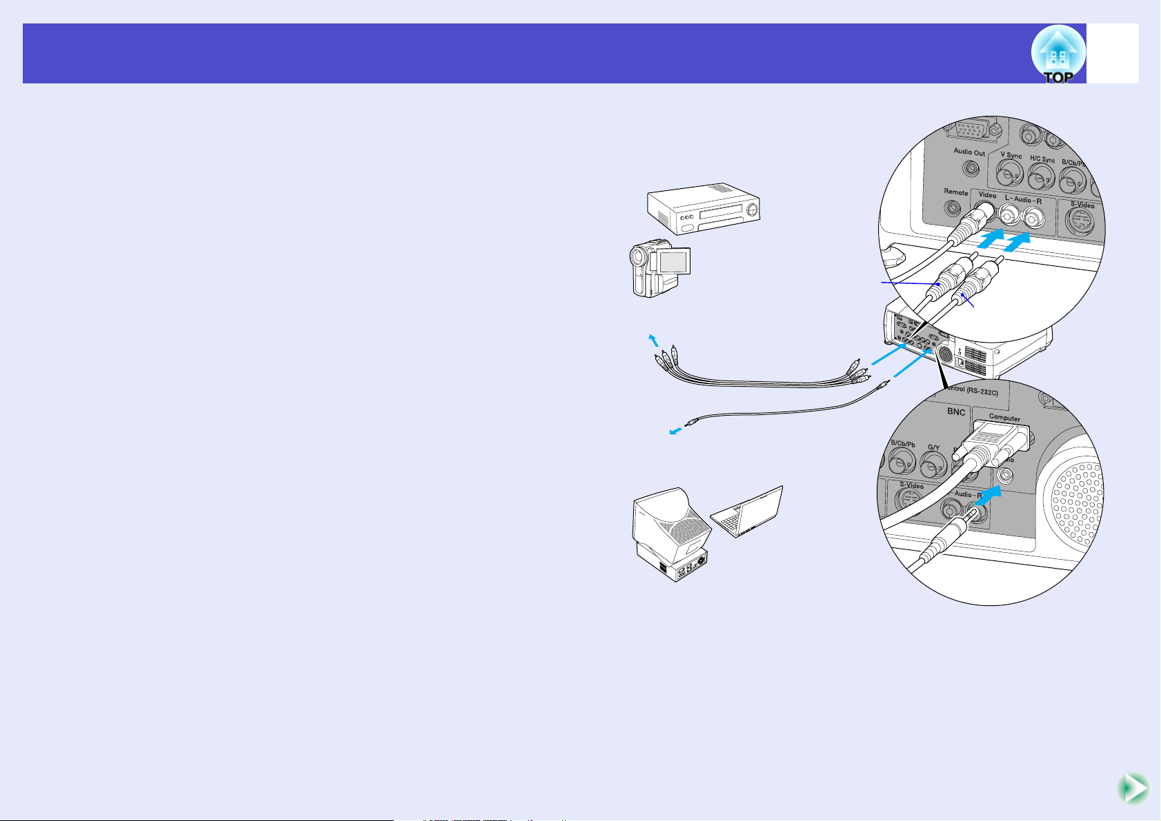
Playing Sound from the Video Equipment
The projector has a built-in speaker with a maximum output of 5 W. You can
output sound from the connected video equipment (such as a computer or
video deck) through the projector's built-in speaker if the video equipment has
an audio output port.
In the case of the [DVI] and [Computer] ports, the [Audio] port to use is the
port that is in the same box as the port being used to input the video signals.
For other ports, the [Audio] port matches the port in the same box that is being
used to input the video signals.
Select the audio cable that is used for this connection from the following,
depending on the shape of the other equipment's port.
• If connecting to a stereo mini jack (such as the audio output port of a
computer): Use a commercially-available stereo mini jack audio cable to
make the connection.
• If connecting to an RCA pin jack ×2 (red/white) (such as the audio output
port of video equipment): Use a commercially-available A/V cable to make
the connection.
29
Page 31

User’s Guide
TIP
• You can adjust the volume after projection has started. p.57
• If the audio signal source is connected to the audio ports that are
used in common with the [DVI] or [Computer] ports, the audio
signals that are being input are output regardless of the image signal
that is selected. The audio signals to be output using the "Computer/
DVI Audio Input" setting in the "Audio" menu can only be set to
"Computer" or "DVI".
• If using a commercially-available 2RCA (L/R)/stereo mini-jack
audio cable, use one that is marked as "No resistance".
Playing Sound from the Video Equipment
30
Page 32

User’s Guide
To external audio equipment
To [Audio Out] port
Audio cable
(commercially-available)
TIP
When a stereo mini-jack audio cable is inserted into the [Audio Out]
port, the sound will be output to external speakers. No sound will be
output from the projector's built-in speaker at this time.
Playing Sound from External Speakers
You can connect speakers with built-in amplifiers to the projector's [Audio
Out] port in order to enjoy a fuller quality of sound.
Use a commercially-available audio cable with pin jack ⇔ stereo mini jack
(3.5 mm) plugs or similar.
Use an audio cable with a plugs that match the ports for the external audio
equipment.
31
Page 33

User’s Guide
TIP
• Use a USB cable less than 3m in length. If the cable exceeds 3m,
CardPlayer may not function correctly.
• Check that there is no wireless LAN card or memory card in the
projector's card slot before connecting any USB device.
To [USB Type A] port
USB cable
To USB port of digital camera
Connecting USB Devices (Digital Camera, Hard Disk Drive or Memory Devices) (EMP-7950 only)
USB1.1-compatible digital cameras, hard disk drives and USB storage devices
can be connected to the projector. Image files that are stored inside the digital
camera and scenarios, images and movies that are stored inside USB storage
devices can be played back with EasyMP CardPlayer. "Showing the
Presentation (Using the CardPlayer)" in the EasyMP Operation Guide
Connecting USB Devices
The following procedure describes how to connect USB devices, using a
digital camera as an example.
Connect a digital camera to the projector using a USB cable provided with,
or specified for use with your digital camera.
CAUTION
32
• If you use a USB hub, the connection may not operate correctly.
Devices such as digital cameras and USB storage devices should be
connected to the projector directly.
• When using a USB-compatible hard disk, be sure to connect the AC
adaptor supplied with the hard disk.
Page 34

User’s Guide
1
2
Connecting USB Devices (Digital Camera, Hard Disk Drive or Memory Devices) (EMP-7950 only)
Disconnecting a USB Device from the Projector
After projection is finished, disconnect the USB device from the projector
using the following procedure.
PROCEDURE
Position the cursor with the "EJECT" button on the
CardPlayer screen and press the [Enter] button on
the remote control to close CardPlayer.
the Presentation (Using the CardPlayer)" in the
EasyMP Operation Guide
CAUTION
Be sure to shut down CardPlayer first before disconnecting a USB
cable or a USB storage device from the projector. If you do not shut
down CardPlayer before disconnecting the USB device, CardPlayer
may no longer operate correctly.
"Showing
33
Disconnect the USB cable or USB storage device
from the projector's [USB Type A] port.
CAUTION
When a USB-compatible hard disk drive is connected, disconnect the
hard disk drive or turn the power for the hard disk drive off before
turning the power for the projector off. If this is not done, it may cause
problems with the projector.
Page 35

Basic Operations
This chapter describes basic operations such as turning projection on and off and adjusting the projected images.
Turning the Projector On.................................... 35
• Connecting the Power Cable..............................................35
• Turning the Power On and Projecting Images .................36
• Selecting an Image Source While Viewing Projected
Images (Preview Function) ................................................38
Turning the Projector Off ................................... 40
Adjusting the Screen Image .............................. 42
• Adjusting the Image Size (Zoom Function)......................42
• Focusing the Screen Images (Focus Adjustment).............42
• Adjusting the Image Angle.................................................43
•Tilting the projector vertically with respect to the screen.......... 43
•When projecting from the side of the screen ............................. 43
•Adjusting the Feets .................................................................... 44
• Manually Correcting Keystone Distortion........................45
•Automatic keystone correction .................................................. 46
•Vertical correction and horizontal correction ............................ 47
Adjusting the Image Quality............................... 51
• Projecting Easy-to-see Images Without a Screen
(Wall Shot)........................................................................... 51
• Adjusting Computer Images ............................................. 53
•Automatic Setup .........................................................................53
•Adjusting the Tracking ...............................................................54
•Adjusting the Sync .....................................................................55
• Selecting the Projection Quality
(Colour Mode Selection) .................................................... 56
Adjusting the Volume.......................................... 57
Preventing theft (Password Protect) ................. 58
• When Password Protect is enabled ................................... 58
•When "Power ON Protect" is enabled (ON) ..............................58
•When "Password Timer" is set to "ON" and "Timer" is used ....59
•When "User’s Logo Protect" is enabled (ON)............................59
• Setting Password Protect ................................................... 60
•Height Correction ...................................................................... 48
•Correcting Keystone Distortion Manually so that
the Projection Area Fits the Screen Exactly (Quick Corner)..... 49
Page 36

User’s Guide
CAUTION
Be sure to read the Safety Instructions/World-Wide Warranty Terms
before projecting images.
TIP
If you change the setting for the "Direct Power ON" command in the
"Advanced2" menu to "ON", the projector's power will turn on and
projection will start at once when you insert the power plug into the
wall outlet. p.93
First turn on the power for other components that are connected to
the projector.
12345
Lit orange
TIP
The remote control and the projector's control panel buttons will not
function while the indicator is flashing orange.
Turning the Projector On
Turn the power on to start projecting images.
Connecting the Power Cable
35
Connect the accessory power cable to the projector.
Check that the power connector is facing the same way as the
power inlet on the projector, and then insert the power cable
connector securely into the projector.
Connect the other end of the power cable to an
earthed electrical outlet.
Wait until the indicator lights orange.
PROCEDURE
Check that the power is turned off for the projector
and all components connected to the projector.
Connect the computer or other video source to the
projector. p.20, p.26
Remove the lens cover.
Page 37

User’s Guide
TIP
• If Password Protect has been enabled, the Password Protect Release
screen will be displayed when the power is turned on.
Type in the password. p.58
• If the "Advanced2" - "Operation Lock" menu setting is set to
"ON", none of the buttons on the projector's control panel will work
except for the [Power] button. p.76
Use the remote control buttons at such times.
1
234
Remote control
Changes from flashing to lit green
TIP
• The remote control and projector's control panel buttons will not
function while the indicator is flashing green.
• Depending on the configuration menu settings, the message "No
Signal." may appear. See "Setting" - "No-Signal Msg." p.86
Turning the Projector On
Turning the Power On and Projecting Images
PROCEDURE
Check that the indicator has stopped flashing and
is lit orange.
36
Press the [Power] button on either the remote control
or the projector's control panel to turn the power on
for the projector.
The indicator flashes green. After a short period it stops
flashing and lights steadily, and projection starts.
Wait until the indicator lights green (it normally takes about
30 seconds to change).
If using the remote control, set the [R/C] switch on the
remote control to "ON".
Turn the power on for all equipment connected to the
projector.
For a video source, press the [Play] button at the video source to
start playback if necessary.
Page 38

User’s Guide
5
Remote control
Turning the Projector On
If more than one external device is connected to the
projector, use the remote control or projector control
panel buttons to select the image source to be
projected while referring to the following table.
You can also use the preview function to select the signal
source. p.38
Button to press
Port
EasyMP*1[EasyMP]
Computer[Comp
DVIg
BNC [BNC]
S-Video [S-Video] S-Video
Video
Remote
control
*2
]
[DVI] DVI
*2
The image source changes
each time [Computer/DVI]
is pressed.
The image source changes
each time [Video/BNC] is
pressed.
Projector
*3
*5
[Video]
On-screen display
EasyMP
Computer (Auto)
Computer (RGB)
Computer
(Component Video)
BNC (Auto)
BNC (RGB)
BNC
(Component Video)
Video
*4
*4
*6
*6
37
*1 Only changes when using the EMP-7950.
EasyMP Operation Guide and the EasyMP Network Setup Guide
for details on using EasyMP.
*2 When these buttons are pressed once, the signal name that is currently
set using the configuration menus appears on the screen.
*3 The input signal will not change to the next signal source unless the
[Computer/DVI] button is pressed while the current signal name is still
being displayed on the screen.
If an input signal from the [DVI] or [Computer] port or EasyMP is
currently being projected, the name of this current input signal will be
displayed on the screen when the [Computer/DVI] button is pressed
once.
*4 The item selected using the "Computer Input" command in the
"Setting" menu will appear.
*5 The input signal will not change to the next signal unless the [Video/
BNC] button is pressed while the current signal name is still being
displayed on the screen.
If an input signal from either of the [BNC], [S-Video] or [Video] ports
is currently being displayed, the name of this current input signal will
be displayed on the screen when the [Video/BNC] button is pressed
once.
*6 The item selected using the "BNC Input" command in the "Setting"
menu will appear.
*4
*6
Page 39

User’s Guide
TIP
• If only one signal source has been connected, the signals from that
source will be projected without needing to press one of the [Source]
buttons.
• If the "No Signal." message does not disappear, check the
connections again.
• If a laptop computer or a computer with an LCD screen has been
connected to the projector, the images may not be projected straight
away. After starting projection, check that the computer has been set
up to output signals externally.
The following table shows examples of how to toggle output settings.
For details, refer to the section of the documentation provided with
your computer under a heading such as "External output",
"Connecting an external monitor" or similar.
• If the same still picture is projected for a long period of time, the
projected image may become burned in on the computer screen. You
should avoid leaving the same image displayed for long periods.
1
Active window
Shows the images that are
currently being projected.
Images from the
[Computer] port
Images from the [DVI] port
Images from the
[S-Video] port
Images from
the [Video] port
Images from the
[BNC] port
EasyMP images
Turning the Projector On
NEC Panasonic Toshiba IBM Sony Fujitsu Macintosh
[Fn]+[F3] [Fn]+[F3] [Fn]+[F5] [Fn]+[F7] [Fn]+[F7] [Fn]+[F10]
Set mirror setting or
display detection.
Selecting an Image Source While Viewing Projected Images (Preview Function)
The preview function lets you project the images from the currentlyselected image source and view them in a preview screen while selecting
the signal source.
Use the remote control to carry out all preview function operations.
PROCEDURE
Press the [Preview] button on the remote control.
After a short while, a preview screen such as the one shown in
the illustration below will appear on the screen.
When the preview screen is being displayed, the frames for
ports that have no image signal being input or which have a
signal being input that is not supported will be solid blue.
Press the [Source] buttons on the remote control to select the
image source to be projected in order to change the image.
Computer (Auto)
Computer
DVI
BNC
Video
S-Video
Easy MP
38
Page 40

User’s Guide
2
3
TIP
• You can hear the sound for the images in the active window while
the preview window is being displayed.
However, if images from a source that is connected to the
[Computer] port or [DVI] port are being projected in the active
window, the audio signals will be output according to the
"Computer/DVI Audio Input" setting in the "Audio" menu.
• Images other than the image in the active window will be projected
as still images.
• If you press the [Preview] button while E-Zoom function is active or
real display is being used, these functions will be cancelled and the
preview screen will be displayed. If you cancel the preview function
without changing the input source, the projected images will return
to the state they were at before the preview function was activated.
Turning the Projector On
Tilt the [ ] button to select the images to be
projected.
Move the red box until the desired image is selected.
Computer (Auto)
BNC
Video
Press the [Enter] button.
The selected images are then projected in the active window.
If you press the [Enter] button once more, the preview function
is cancelled and the images in the active window are projected.
S-Video
39
Computer
DVI
Easy MP
To return to the images that were being projected before the
preview function was activated, press the [ESC] or [Preview]
button.
DVI
Computer
DVI
BNC
Video
S-Video
Easy MP
Page 41

User’s Guide
1
2
Remote control
TIP
If the message "The projector is overheating. Make sure nothing is
blocking the air vent, and clean or replace the air filter." appears on
the screen, press the [Enter] button on the remote control or the
[Auto/Enter] button on the projector's control panel to turn the power
off and then clean the air filters. p.140
3
Stops flashing and lights orange
TIP
• The remote control and projector's control panel buttons cannot be
operated while the indicator is flashing orange. Wait until it lights
constantly.
• If "Standby Mode" in the configuration menu is set to "Network
ON", fans will continue operating. This is normal and does not
indicate a problem.
Turning the Projector Off
Follow the procedure below to turn the projector off.
PROCEDURE
Turn the power off for the signal sources that are
connected to the projector.
Check that the power for all connected components has been
turned off.
Press the [Power] button on either the remote control
or the projector's control panel.
40
Press the [Power] button on either the remote control
or the projector's control panel once more.
The lamp will switch off. The indicator will flash orange and
cool-down
The cool-down period lasts for about 20 seconds.
When cool-down is complete, the indicator lights orange.
g will start.
The following confirmation message will appear.
Power OFF?
: Press button
Yes
No : Press any other button
If you do not want to turn the power off, press a button other
than any of the following:
• At the remote control: [Power], [ ], [ ], [ ], [Num], [ID]
• At the control panel : [Power]
If you do not press any button, the message will disappear
automatically after seven seconds. (The power will not turn off
at this time.)
Page 42

User’s Guide
4
CAUTION
Do not disconnect the power cable from the electrical outlet while the
indicator is flashing orange, otherwise operating problems may
result.
5
TIP
If you leave the [R/C] switch on the remote control at "ON", it will
consume battery power. When not using the remote control, set the
[R/C] switch to "OFF".
6
Lens cover
Turning the Projector Off
If not using the projector for a long period, unplug the
power cable from the electrical outlet.
Set the [R/C] switch on the remote control to "OFF".
41
Attach the lens cover.
Attach the lens cover to the lens when not using the projector,
in order to stop the lens from getting dusty or dirty.
Page 43

User’s Guide
TIP
The E-Zoom function can also be used to enlarge parts of the images.
p.64
Turn to "W" to
increase the size
Zoom ring
Turn to "T" to
reduce the size
Focus ring
TIP
• If the surface of the lens is dirty or misted over as a result of
condensation, it may not be possible to adjust the focus correctly. If
this happens, clean or de-mist the lens. p.123, p.140
• If using the standard lens or an optional wide zoom lens and the
projector is positioned outside the normal projecting range of 77–1113
cm (2.5–36.5 ft.), it may not be possible to obtain the correct focus.
If you have trouble obtaining the correct focus, check the projection
distance. If an optional lens is fitted, refer to the documentation for the
optional lens for further details.
Adjusting the Screen Image
You can correct and adjust the screen images in order to obtain the best
possible pictures.
Adjusting the Image Size (Zoom Function)
The size of the projected images is basically determined by the distance
from the projector to the screen. p.16
The following procedures explain how to adjust the screen images once the
projector itself has been set up.
PROCEDURE
Turn the zoom ring on the projector to adjust the image.
42
Focusing the Screen Images (Focus Adjustment)
PROCEDURE
Turn the focus ring to adjust the image focus.
If keystone correction or Sharpness settings have been made, it may
not be possible to adjust the focus correctly.
If a standard lens or an optional wide zoom lens is fitted, the images
can be enlarged in this way to 1.35 times the normal size.
If you would like to enlarge the images further, move the projector
further away from the screen.
p.16
Page 44

User’s Guide
CAUTION
The maximum downward tilt angle is when the rear adjustable foot is
extended to its limit. Do not tilt the projector downward any further
than extending the foot.
Adjusting the Screen Image
Adjusting the Image Angle
If the projector is set up so that it is at a horizontal or vertical angle to the
screen, adjust as follows.
Tilting the projector vertically with respect to the screen
If the images are being projected onto a screen that is higher than the
position of the projector, extend the front adjustable foot to tilt the
projector. p.44
Tilting the projector may cause a keystone distortion to the image, but the
automatic keystone correction function will automatically corrects the
image distortion. p.46
43
When projecting from the side of the screen
If the projector cannot be set up directly in front of the screen, you can
project images at a horizontal angle to the screen. If keystone distortion
appears in the images, you can use the projector's "H-Keystone" and
"Quick Corner" functions to correct this keystone distortion. p.47, p.49
Page 45

User’s Guide
TIP
If you use the front adjustable foot and the rear adjustable feet to
adjust the tilt of the projector, it may cause keystone distortion to
appear in the projected images. If this happens, the Auto Keystone
function will operate to automatically project images without keystone
distortion.
p.45
Foot adjust lever (Front)
TIP
If the projector is tilted vertically or horizontally, turn the bases of the
rear adjustable feet to make fine adjustments to the height of the
projector. When the projector is tilted horizontally, the correction may
not be carried out correctly.
Adjusting the Screen Image
Adjusting the Feets
The front adjustable foot and the rear adjustable feet can be extended and
retracted to adjust the tilt of the projector to a maximum of 12º upward and
4º downward.
PROCEDURE
While pulling the foot adjust lever at the front of the
projector, lift up the front of the projector to extend the
front adjustable foot.
44
Rear
adjustable foot
Extend Retract
Extend the front adjustable foot until the desired angle is obtained,
and then release the foot adjust lever.
To retract the front adjustable foot, gently push down on the projector
while pulling the foot adjust lever.
Page 46

User’s Guide
TIP
Keystone correction is carried out automatically within a range of
approximately 30º up or down. Manual keystone correction can be
carried out within a range of approximately 40º up or down or 20º to
the left or right.
However, the applicable angles will become smaller under the
following conditions.
• If the projector has been tilted both horizontally and vertically
• If an optional projection lens has been fitted
• When the zoom is set to "W"
Adjusting the Screen Image
Manually Correcting Keystone Distortion
This projector is equipped with an automatic keystone correction function
that detects the vertical angle of the projector during projection and
automatically corrects vertical keystone distortion. If you would like to
make further fine adjustments after automatic keystone correction has been
carried out, or if the projector is tilted horizontally, you can carry out
keystone correction manually.
45
This projector is equipped with the following two keystone correction
functions. Use whichever function is appropriate for the keystone
distortion that appears.
• Auto Keystone/H/V-Keystone
Automatic keystone automatically corrects keystone distortion when the
projected images are vertically distorted.
H/V-Keystone can be used to make fine adjustments to the results of
automatic keystone correction and to correct horizontal keystone
distortion.
The keystone correction function lets you easily correct keystone
distortion that has occurred after moving the projector, simply by using
buttons on the projector's control panel.
See "Automatic keystone correction" p.46
"Vertical correction and horizontal correction" p.47
"Height Correction" p.48
• Quick Corner:
This correction function is used when both horizontal and vertical
keystone distortion occurs in the projection area to adjust the projection
area so that it fits the screen exactly. p.49
Page 47

User’s Guide
TIP
• The "Auto Keystone", "H/V-Keystone" and "Quick Corner"
functions cannot both be used together to correct keystone distortion.
If you use one function to correct keystone distortion, any correction
that has been applied using the other function will be cancelled.
• The larger the angle of tilt, the poorer the focus of the contours in
the projected images will become.
• If a large amount of keystone correction is applied, fine details such
as text characters and lines may go out of focus.
• Keystone corrections that have been applied using the keystone
correction functions are memorised even when the projector's power
is turned off. If you have changed the projection position or angle,
you will need to repeat the correction procedure.
• "H-Keystone" and "Height" cannot be used at the same time.
• When keystone correction is carried out, the projected images will
become smaller. Use the zoom function to adjust the size of the
images if necessary. p.42
• If the text part of the image is blurred after keystone correction is
carried out, decrease the sharpness setting. p.78, p.81
TIP
• Automatic keystone correction is not carried out if "Rear Proj." or
"Ceiling" in the "Advanced1" menu is set to "ON", or if the
projection area has been corrected manually using the "Quick
Corner" function.
• If you would like to make further fine adjustments after automatic
keystone correction has been carried out, or if the projector is tilted
horizontally, you can carry out keystone correction manually.
p.47
• If you do not want automatic keystone correction to be carried out,
change the "Auto Keystone" setting in the "H/V-Keystone" submenu of the "Keystone" command in the "Setting" menu to "OFF".
p.85
Adjusting the Screen Image
46
Automatic keystone correction
When the projector has been tilted vertically, automatic keystone
correction is carried out so that images with no distortion are projected.
Automatic keystone correction is carried out approximately one second
after the projector is set up and projection starts. A vertical keystone
correction gauge appears on the screen while automatic adjustment is in
progress.
Page 48

User’s Guide
TIP
If "Quick Corner" is selected in the "Keystone" sub-menu of the
"Setting" menu, the "Quick Corner" correction screen will be
displayed if you press the [ ], [ ], [ ] or [ ] buttons. p.49
When carrying out vertical correction and horizontal correction,
select "H/V-Keystone" and then make the correction. p.85
Projector
Projector
If the top of the
image is elongated
If the bottom of the
image is elongated
Projector
Projector
If the left edge of the
image is elongated
If the right edge of the
image is elongated
TIP
If the value displayed in the gauge on the screen stops changing when
vertical correction and horizontal correction is being carried out, it
indicates that the limit for vertical correction and horizontal
correction has been exceeded. Check that the projector has not been
set up at an angle which exceeds the proper limit.
Adjusting the Screen Image
Vertical correction and horizontal correction
Vertical correction and horizontal correction can be carried out using either
the projector's control panel or the configuration menus. This procedure
explains how to use the projector's control panel to correct keystone
distortion.
For adjustment using the configuration menus: - "Setting" - "Keystone" "H/V-Keystone" p.85
If you use the horizontal correction function when height correction
adjustment has already been carried out, the height correction adjustment
will be cancelled.
47
PROCEDURE
Page 49

User’s Guide
1
2
Select
[ ESC ]:
Retur
[Men
u]:
Exit
Adjust
Video
udio
Setting
User's Logo
Adv
anced1
Reset All
About
Adv
anced2
Eff
Auto Keystone
Height
Keystone
H-Keystone
V-Keystone
32
OFF
3
Adjusting the Screen Image
Height Correction
When Automatic keystone correction and horizontal correction is carried
out, the height of the projected images will become shorter. Use the height
correction function to adjust the height of the projection area.
The height correction function is accessible from the configuration menu.
This cannot be set when vertical correction is carried out.
PROCEDURE
Press the [Menu] button on either the remote control
or the projector's control panel. Then select "Height"
from the "H/V-Keystone" sub-item of the "Keystone"
command in the "Setting" menu.
For details, refer to "Using the Configuration Menus" p.96
Video
Audio
Effect
Setting
User's Logo
Advanced1
Advanced2
About
Reset All
Auto Keystone
V-Keystone
H-Keystone
Height
ON OFF
:
32
:
0
:
:
0
Keystone
-
-
-
+
+
+
Tilt the [ ] button on the remote control to the left or
right, or press the [ ] or [ ] buttons on the
projector's control panel to correct the height while
viewing the projected images.
[ ESC ]:
Video
Audio
Eff
ect
Setting
User's Logo
Adv
anced1
Adv
anced2
About
Reset All
Retur
n
[ ]: Select
Auto Keystone
V-Keystone
H-Keystone
Height
[ ]: Adjust
:
:
:
:
48
Keystone
ONONOFF
32
0
+
-
+
-
+
-
[Men
u]:
Exit
When the adjustment is complete, press the [Menu]
button on the remote control or the projector's
control panel to close the configuration menu.
48
[ ]: Select[ ESC ]: Return
[ ]: Adjust
[Menu]: Exit
Page 50

User’s Guide
TIP
If "H/V-Keystone" is selected in the "Keystone" sub-menu of the
"Setting" menu, the "V-Keystone" or "H-Keystone" adjustment gauge
will be displayed if you press the [ ], [ ], [ ] or [ ] buttons.
p.47
When carrying out "Quick Corner" correction, select "Quick Corner"
and then make the correction. p.85
1
2
The selected
angle will
appear yellow.
Adjusting the Screen Image
Correcting Keystone Distortion so that the Projection
Area Fits the Screen Exactly (Quick Corner)
Quick Corner correction can be carried out using either the projector's
control panel or the configuration menus. This procedure explains how to
use the projector's control panel to correct keystone distortion.
If using the configuration menu: "Setting" - "Keystone" - "Quick Corner"
p.85
PROCEDURE
Press the [ ], [ ], [ ] or [ ] button on the
projector's control panel.
[ ]:Adjust
/
[ ] :Move next
[ESC] :Return (Press 1 second to
reset)
Press the [Auto/Enter] button on the projector's
control panel and then select the corner to be
corrected on the screen.
You can also press the [Enter] button on the remote control to
select the corner.
49
The Quick Corner correction screen will be displayed.
[ ]:Adjust
/
[ ] :Move next
[ESC] :Return (Press 1 second to
reset)
Page 51

User’s Guide
3
Screen
TIP
• If you press down the [ESC] button on the remote control or the
projector's control panel for one second while the Quick Corner
correction screen is displayed, the correction results will be restored
to their default values.
• If the message "Cannot move anymore." appears on the screen
while using the Quick Corner function, it means that the limit for
correction has been reached. Check the following two points.
· Is the projection distance appropriate for the size of the projection
screen? p.16
· Is the projector tilted too much? p.45
• If the input signal is interrupted or an image signal that is not
supported is input while using the Quick Corner function, the
correction value at that point will be recorded and the Quick Corner
function will be cancelled.
• When the Quick Corner correction screen is displayed, the following
functions will be cancelled.
· E-Zoom function · Real display · Freeze
4
Adjusting the Screen Image
Press the [ ], [ ], [ ] and [ ] buttons on the
remote control to correct the angle position.
You can also tilt the [ ] button on the remote control to correct
the angle position.
[ ]:Adjust
/
[ ] :Move next
[ESC] :Return (Press 1 second to
reset)
50
When the adjustment is complete, press the [Menu]
button on either the remote control or the projector's
control panel to close the configuration menu.
Page 52

User’s Guide
TIP
Wall Shot can be used for adjustment if the projection distance is
within approximately 80–1000 cm (2.6–32.8 ft.). However, this
distance will vary depending on the condition of the projected surface,
for instance if the projection surface is an extremely reflective surface
such as a whiteboard, or if it is a highly non-reflective surface such as
a dark wall.
1
Remote control
Adjusting the Image Quality
The quality of the projected images can be adjusted as follows.
Projecting Easy-to-see Images Without a Screen (Wall Shot)
When the Wall Shot function is used, images can be projected without loss
of original colour even onto surfaces such as blackboards and coloured
wall surfaces which are being used instead of a screen. For example, if
projecting onto a green blackboard, the projected images would normally
appear greenish and be very difficult to see. The Wall Shot function uses a
sensor to measure the condition of the projection surface and automatically
adjusts the colour of the projected images based on these measurements.
The Wall Shot function also allows shading to be adjusted. If projecting
onto a screen that is located near a window, the Wall Shot function can be
used to obtain clear images when they might otherwise appear faded.
51
PROCEDURE
The Wall Shot function can be operated using either the remote control or
the projector's control panel.
Press the [Wall Shot] button on either the remote
control or the projector's control panel while the
images are being projected.
When the button is pressed, the current status is displayed on
the screen.
Page 53

User’s Guide
2
3
• When the projector's power is turned off, images will be projected
next time with the status set to "Wall Shot OFF". However, the
correction values that were obtained by the previous measurement
operation will be stored even when the power is turned off.
If projecting in the same location as before, you can retrieve the
colour correction values that were used previously (the five seconds
required for readjustment will not be necessary).
The status will change as follows each time the [Wall Shot] button is
pressed.
When "Wall Shot retrieval" is selected, the previous adjustment
values are retrieved.
• If you change the projection location or change the condition of the
projection surface, you should repeat the Wall Shot measurements.
If you press the [Wall Shot] button twice while "Wall Shot ON" is
being displayed, "Wall Shot Readjustment" will be displayed and
adjustment will then start.
Adjusting the Image Quality
To change the status, press the [Wall Shot] button
while the status is being displayed on the screen.
For example, if you press the [Wall Shot] button while "Wall
Shot OFF" is displayed, the status will change to "Wall Shot
ON" and measurement of the projection surface will start.
Colours in the order red → green → blue → black will be
projected for approximately five seconds while measurement is
in progress.
Wall Shot ON
Once the measurement is finished and colour
correction is complete, the images will be projected
in the corrected condition.
To cancel the correction, press the [Wall Shot] button while
"Wall Shot ON" is being displayed on the screen so that "Wall
Shot OFF" is selected.
TIP
Wall Shot OFF
Wall Shot ON
52
Wall Shot ON
Wall Shot Memory Call
Wall Shot OFF
Wall Shot Readjustment
Page 54

User’s Guide
TIP
• If "Auto Setup" in the "Advanced2" menu is set to "OFF" (the
default setting for this command is "ON"), automatic setup is not
carried out. If you press the [Auto] button on the remote control or
the [Auto/Enter] button on the projector's control panel while
computer images (analogue RGB signals) are being projected,
adjustment will then be carried out.
• If you press the [Auto] button on the remote control or the [Auto/
Enter] button on the projector's control panel while the E-Zoom
function or Freeze function is active, the active function will be
cancelled and then the adjustment will be carried out.
• Sometimes the signals may not be adjusted correctly depending on
the type of signals being output by the computer. In such cases, use
the "Tracking", "Position" and "Sync." menu commands to make
the adjustments manually. p.54, p.55, p.78
• Automatic setup is not carried out while the preview function is
being used.
Adjusting the Image Quality
Adjusting Computer Images
Automatic Setup
Automatic setup detects analogue RGB signals coming from a connected
computer, and automatically adjusts these signals so that the optimum
images can be obtained.
Automatic setup involves adjustment of the following three items:
Trackingg, Position and Syncg.
53
Remote control
Page 55

User’s Guide
Projector
Projector
TIP
The images will flash when continuous tracking adjustment is carried
out, but this is normal.
Adjusting the Image Quality
l
Adjusting the Tracking
If vertical stripes appear in the projected images,
and this cannot be fixed using automatic setup,
you will need to adjust the trackingg manually
using the following procedure.
PROCEDURE
Tracking adjustment can be carried out using either the projector's
control panel or the configuration menus. This procedure explains
how to use the projector's control panel to adjust the tracking.
For adjustment using the configuration menus:
See "Video" - "Tracking" p.78
Press the following buttons to adjust the tracking value until the
vertical stripes disappear from the projected images.
54
While holding down the [Shift] button on the projector's
control panel, press the [ ] button.
The tracking value decreases each time the button is pressed.
While holding down the [Shift] button on the projector's
control panel, press the [ ] button.
The tracking value increases each time the button is pressed.
Page 56

User’s Guide
Projector
Projector
TIP
• If you adjust the sync without adjusting the tracking first, it will not
be possible to get the best adjustment results. Incorrect tracking
adjustment may not be noticeable with some types of image.
However, images with lots of lines and shading will tend to show
incorrect tracking adjustments more clearly, so be sure to check the
tracking adjustment first.
• It may also be possible to fix flickering and fuzziness by adjusting
the brightness, contrast
g
, sharpness and keystone correction
settings.
Adjusting the Image Quality
Adjusting the Sync
If flickering, fuzziness or interference appear in
images that are input from the computer, and this
cannot be fixed using automatic setup, you will
need to adjust the syncg manually using the
following procedure.
PROCEDURE
Sync adjustment can be carried out using either the projector's
control panel or the configuration menus. This procedure explains
how to use the projector's control panel to adjust the sync.
For adjustment using the configuration menus:
See "Video" - "Sync." p.78
Press the following buttons to adjust the sync value until the
flickering, fuzziness or interference disappears from the projected
images.
55
While holding down the [Shift] button on the projector's
control panel, press the [ ] button.
The sync value decreases each time the button is pressed.
While holding down the [Shift] button on the projector's
control panel, press the [ ] button.
The sync value increases each time the button is pressed.
Page 57

User’s Guide
Remote control
Adjusting the Image Quality
Selecting the Projection Quality (Colour Mode Selection)
The following five preset colour modes are available for use depending on
the characteristics of the images that are being projected. You can easily
obtain the optimum image quality simply by selecting the colour mode that
corresponds to the projected images. The brightness of the images will
vary depending on which colour mode is selected.
Mode Application
Dynamic Images are modulated and made fresher to emphasise
brightness.
Presentation Brightness is emphasised. For presentations in bright rooms.
Theatre Movie images are optimised using natural tints.
Living Room Brightness is emphasised. Ideal for playing video games in
bright rooms.
g
sRGB
Images conform to the sRGB colour standard. If the connected
source has a sRGB mode, set both the projector and the
connected signal source to sRGB.
PROCEDURE
Selecting the colour mode can be carried out using either the remote
control or the configuration menus. This procedure explains how to
use the remote control to select the colour mode.
For selecting using the configuration menus
See "Video" - "Color Mode"
p.79, p.81
The colour mode changes as follows each time the [Color
Mode] button on the remote control is pressed.
Dynamic → Presentation → Theatre → Living Room → sRGB ...
56
The current setting is displayed on the screen each time the mode is
changed.
The default setting for the colour mode is as follows:
When computer images are being input: "Presentation"
When other types of images are being projected: "Dynamic"
Presentation
Page 58

User’s Guide
Volume
Remote control
TIP
• If the value displayed in the gauge on the screen stops changing
when the volume is being adjusted, it indicates that the limit for
volume adjustment has been reached.
• The volume adjustments are stored individually for each image
source.
Adjusting the Volume
You can adjust the volume for the sound from the projector's built-in speaker
or from the external speakers that are connected to the projector.
PROCEDURE
The volume can be adjusted using either the remote control, the projector's
control panel or the configuration menus. This procedure explains how to
use the remote control and the projector's control panel to adjust the
volume.
For adjustment using the configuration menus:
See "Audio" - "Volume" p.83
Press the [Volume] button on either the remote control or
the projector's control panel.
When the button is pressed to the [ ] side, the volume increases, and when it is
pressed to the [ ] side, the volume decreases.
The volume gauge appears on the screen when the volume is being adjusted.
57
Volume
:
15
-
+
Page 59

User’s Guide
Remote control
The buttons inside the box will switch
to numeric keypad mode while the
[Num] button is lit.
Numeric buttons
Preventing theft (Password Protect)
When the Password Protect function is activated, people who do not know the
password cannot use the projector to project images when the power is turned
on. Furthermore, the user's logo that is displayed on the background of the
screen cannot be changed. This is effective against theft.
When turning the projector's power on for the first time after the purchase, the
projection will start without entering a password. It is recommended that you
enable the Password Protect function promptly.
When Password Protect is enabled
When "Power ON Protect" is enabled (ON)
When the power is turned on for the first time after the projector's power
cable is connected to the electrical outlet, or when Direct Power On is
carried out, the following password entry screen will be displayed.
Password
Enter the password.
58
Use the numeric buttons on the remote control to set the password.
Press the [Num] button on the remote control to enter the password.
If you press the [Num] button, it will light up and the remote control
buttons will change to numeric keypad mode so that you can enter
numbers.
If you press the [Num] button once more, it will stop lighting up and
numeric keypad mode will be cancelled.
If the correct password is entered, projection will then start.
#Refer to the "User's Guide" for the operation.
[0-9]:Enter
If you leave the power cable connected to the electrical outlet and turn the
projector's power on when it is in standby mode, projection will start
without the password entry screen appearing. The password entry screen
will only be displayed when the power is turned on for the first time after
the power cable has been disconnected and then reconnected. If Direct
Power On is set to "ON" and you are using a circuit breaker or similar to
centrally control the power, the password entry screen will be displayed the
first time the projector is turned on after the power supply is restored.
Page 60

User’s Guide
TIP
• If an incorrect password is entered three times in succession, the
message "The projector’s operation will be locked." will be displayed
for approximately five minutes, and then the projector will switch to
standby mode. If this happens, disconnect the power plug from the
electrical outlet and then reinsert it and turn the projector's power
back on. A window requesting you to enter the password will be
displayed, so enter the correct password.
If you happen to forget the password, make a note of the "Request
Code: xxxxx" number that appears in the Password screen and
contact the nearest address provided in the "International Warranty
Conditions" section of the Safety Instructions/World-Wide Warranty
Terms booklet.
• If you repeat the above operations ten times resulting in an incorrect
password being entered thirty times, the following message will be
displayed and the projector will not accept password entries any
more.
"The projector’s operation will be locked. Contact the nearest
address provided in the "International Warranty Conditions" section
of the Safety Instructions/World Wide Warranty Terms booklet."
Preventing theft (Password Protect)
59
When "Password Timer" is set to "ON" and "Timer" is used
The password entry screen will not be displayed at all when the power is
turned on until the length of time that has been set has elapsed. When the
set length of time has elapsed, the password entry screen will be displayed
each time the power is turned on. The length of time referred to here is the
total illumination time for the projector's lamp from the point when the
projector's menu is closed.
If "Password Timer" is set to "OFF", the password entry screen will be
displayed each time the power plug is disconnected and reinserted from the
electrical outlet. If the projector's power on when it is in standby mode, the
password entry screen will not be displayed.
When "User’s Logo Protect" is enabled (ON)
If an attempt is made to carry out any of the following user logo
operations, a message is displayed and the setting cannot be changed. To
change the setting, set "User’s Logo Protect" to "OFF" first. p.61
• Capturing a user's logo
• Changing the setting for the "No-Signal Msg." command in the "Setting"
menu from "Logo" to "Black", "Blue" or "OFF", or when changing it
from "Black", "Blue" or "OFF" to "Logo"
• Changing the setting for the "A/V Mute" command in the "Setting" menu
from "Logo" to "Black" or "Blue", or when changing it from "Black" or
"Blue" to "Logo"
• When the "Advanced1" - "Startup Screen" menu setting ("ON" or "OFF")
is changed.
Page 61

User’s Guide
1
Remote control
TIP
• If Password Protect has already been enabled, the screen requesting
a password will be displayed.
When the correct password has been entered, the "Password
Protect" menu will be displayed.
See"When Password Protect is enabled" p.58
• When Password Protect has been set to "ON", attach the Password
Protect stickers to your preferred place on the projector to increase
anti-theft effectiveness.
2
3
Preventing theft (Password Protect)
Setting Password Protect
Use the following procedure to set Password Protect.
PROCEDURE
Press the [Freeze] button on the remote control for
approximately five seconds.
If using the projector's control panel, hold down the
[ ] button and press the [Menu] button for
approximately five seconds.
The Password Protect menu will be displayed.
Password Protect
:
ON: OFF
ON: OFF
Set 9999H
0H
ON: OFF
Set
Power ON Protect
Password Timer
Timer
Time-elapsed
User's Logo Protect
Passward
60
Turn "Power ON Protect" on.
(1) Select "Power ON Protect", and then press the [Enter]
button on the remote control or the [Auto/Enter] button on
the projector's control panel.
(2) Select "ON", and then press the [Enter] button on the
remote control or the [Auto/Enter] button on the
projector's control panel.
(3) Press the [ESC] button on either the remote control or the
projector's control panel.
If "Password Timer" is set to "ON", "Timer" can be
used to specify a time limit to use the projector
without entering the password.
If you don't use this setting, proceed to step 4.
(1) Select "Timer" and then press the [Enter] button on the
remote control or the [Auto/Enter] button on the
projector's control panel.
(2) Press the [Num] button on the remote control and use the
numeric buttons to enter a setting time within the range of
1 to 9999 hours, then press the [Enter] button on the
remote control or the [Auto/Enter] button on the
projector's control panel. If you make a mistake entering
the time, press the [ESC] button on either the remote
control or the projector's control panel and re-enter the
time.
When you have finished using the "Password Protect"
menu, the countdown for the elapsed time will start.
Page 62

User’s Guide
456
TIP
• When the set time has elapsed and the password is entered,
projection will start and the "Timer-elapsed" counter will be cleared
to count again.
• Make a note of the password so that you do not forget it and keep it
in a safe place.
• If you lose the remote control, you will not be able to enter the
password. Keep the remote control in a safe place at all times.
Preventing theft (Password Protect)
Turn "Us er ’s Logo Protect" on.
(1) Select "User’s Logo Protect", and then press the [Enter]
button on the remote control or the [Auto/Enter] button on
the projector's control panel.
(2) Select "ON", and then press the [Enter] button on the
remote control or the [Auto/Enter] button on the
projector's control panel.
(3) Press the [ESC] button on either the remote control or the
projector's control panel.
Enter the password.
(1) To set a password, select "Password" and then press the
[Enter] button on the remote control or the [Auto/Enter]
button on the projector's control panel.
(2) The message "Change the password?" will be displayed,
so select "Yes" and then press the [Enter] button on the
remote control or the [Auto/Enter] button on the
projector's control panel.
The default setting for the password is "0000", but you
should change this to your own desired password.
If you select "No", the screen shown at step 1 will be
displayed again.
(3) Enables numeric keypad of the remote control and enter a
4-digit password.
The password entered will be displayed as "****".
Once four digits have been entered, the confirmation
screen will be displayed.
(4) Re-enter the password.
The message "The new password is stored." will be
displayed.
If you enter the password incorrectly, a message will be
displayed prompting you to re-enter the password.
61
Once the setting is complete, press the [Menu]
button.
Press the [Num] button on the remote control to
cancel numeric keypad mode.
Check that the [Num] button indicator is turned off.
Page 63

Advanced Operations
This chapter describes functions for enhancing the projection of images, and how to use the configuration menus.
Functions for Enhancing Projection ................. 63
• A/V Mute Function .............................................................63
• Freeze Function ...................................................................64
• E-Zoom Function ................................................................64
• P in P (Picture in Picture) Function ..................................65
• Effect Function ....................................................................67
•Using the Pointer Icon ............................................................... 67
•Drawing Straight and Curved Lines .......................................... 68
• Preset Function....................................................................69
•Saving "Video" Menu Settings .................................................. 69
•Applying Saved "Video" Menu Settings.................................... 71
• Changing the Resize/Aspect Ratio.....................................71
•Selecting the Computer Display Method................................... 71
•Projecting Wide-screen Images from Video Equipment ........... 73
• Projector ID/Remote Control ID .......................................74
•Registering an ID Number for a Projector................................. 74
•Registering an ID Number for a Remote Control...................... 75
• Operation Button Lock Function ......................................76
Using the Configuration Menu Functions ........ 77
• List of Functions..................................................................78
•"Video" Menu ............................................................................ 78
•"Audio" Menu............................................................................ 83
•"Effect" Menu ............................................................................ 84
•"Setting" Menu .......................................................................... 85
•"User's Logo" Menu .................................................................. 88
•"Advanced1" Menu.................................................................... 89
•"About" Menu ............................................................................94
•"Reset All" Menu .......................................................................95
• Using the Configuration Menus ........................................ 96
Monitoring and Controlling Projectors via a
Network (for the EMP-7900).............................. 98
• Available Network Functions for the EMP-7900 ............. 98
•Monitoring Function Using SNMP and the SNMP Manager
Program ......................................................................................98
•Monitoring and Control Functions Using the
Accessory Software....................................................................98
• Compatible Computers...................................................... 99
•Computers that can run EMP Monitor .......................................99
•Computers that can run EMP NetworkManager ........................99
• Installing and Uninstalling the Projector Software......... 99
•Installing the software ................................................................99
•Uninstalling the software .........................................................100
• Network Cable Connections ............................................ 101
• Projector Connection Settings......................................... 101
•Network connections using the configuration menus ..............101
• Problem Reporting Using the Mail Notification
Function ............................................................................ 103
•Mail Notification Settings ........................................................103
•If a Problem Notification is Sent By Mail................................106
•Connecting Manually ...............................................................106
•Sharing EMP Monitor settings .................................................107
Centralised Control using EMP Monitor ......... 108
•"Advanced2" Menu.................................................................... 92
Page 64

User’s Guide
Remote control
Default setting
Solid black
Solid blue
User's logo
TIP
• The default user's logo is the EPSON logo. You can change the
user's logo by recording and setting your own logo. p.148
• When the A/V Mute function is being used, the "Brightness
Control" setting in the "Setting" menu to will automatically change
to "Low". When the A/V mute function is cancelled, the "Brightness
Control" setting will return to the original setting.
Functions for Enhancing Projection
This section describes the various useful functions that can be used to enhance
presentations.
A/V Mute Function
This function momentarily pauses the images and sound.
For example, it can be used when you do not wish to show details of
operations such as selecting different files while computer images are
being projected.
However, if you use this function when projecting moving images, the
images and sound will still continue to be played back by the source, and
you cannot return to the point where the A/V Mute function was activated.
PROCEDURE
Press the [A/V Mute] button on either the remote control
or the projector's control panel.
The images and sound will then be paused.
63
You can use the "A/V Mute" command in the "Setting" menu to set
the screen appearance when the images and sound have been paused
to any one of the following three settings. p.86
Press the [A/V Mute] button once more to continue normal
projection.
You can also continue normal projection by pressing the [ESC] key
on either the remote control or the projector's control panel.
Page 65

User’s Guide
Remote control
TIP
• If you press the [Freeze] button on the remote control while a
configuration menu or help menu is displayed, the configuration
menu and help menu display is cancelled.
• The Freeze function also works while the E-Zoom function is being
used.
1
Remote control
2
Cross
Functions for Enhancing Projection
Freeze Function
This function pauses only the projected images. The sound keeps playing
without pausing.
The signal source will still be playing back the images even while
projection is paused, and so it will not be possible to resume projection
from the point where it was paused.
PROCEDURE
Press the [Freeze] button on the remote control.
The images will then be paused.
To continue projecting the images, press the [Freeze] button once
more. You can also continue normal projection by pressing the [ESC]
button on either the remote control or the projector's control panel.
64
E-Zoom Function
This function lets you enlarge and reduce a parts of projected images such
as graphs and tables.
The E-Zoom function is controlled using the remote control.
PROCEDURE
Press the [E-Zoom ] button on the remote control.
A cursor (cross) indicating the centre point for the area to be
enlarged will appear on the screen.
Move the cross to the area of the image that is to be
enlarged.
Tilt the [ ] button on the remote control to move the cross.
Page 66

User’s Guide
3
Shows enlargement ratio
TIP
• The selected area can be enlarged to between 1–4 times, in 25 steps
of
××××
0.125.
• When you reduce the size to
××××
1, the E-Zoom function will be
cancelled.
• You can use the Effect function with the enlarged image. p.67
TIP
The P in P function cannot be used for computer images that have the
refresh rate
g
set to interlacedg, nor for RGB video images.
1
Sub-screen
Operation guide
Functions for Enhancing Projection
When the [ ] button is pressed, the image is enlarged
with the cross at its centre. When the [ ] button is
pressed, the enlarged image is then reduced.
The enlargement ratio will appear at the bottom-right of the
screen.
You can scroll around the image by tilting the [ ] button.
To cancel the E-Zoom function, press the [ESC] button.
65
P in P (Picture in Picture) Function
This function lets you display separate images in a smaller screen (subscreen) over the top of the images that are currently being projected (main
screen).
Computer images can be displayed in the main screen, and video images
(composite videog or S-Videog) can be displayed in the sub-screen.
The video images in the sub-screen can be selected using the "P in P"
command in the "Setting" menu. p.86
The P in P function is controlled using the remote control.
PROCEDURE
Connect the equipment to be used for projecting the
main screen and sub-screen images, set the type of
sub-screen using the "P in P" command in the
"Setting" menu, and then press the [PinP] button on
the remote control.
The sub-screen will appear at the top-left of the screen, and the
operation guide will appear at the bottom-left of the screen.
Page 67

User’s Guide
2
3
Size 1
Approx.
1/3.4
Size 2
Approx.
1/3.2
Size 3
Approx.
1/3.0
Size 4
Approx.
1/2.8
Size 5
Approx.
1/2.7
4
TIP
• The position of the sub-screen is memorised, so that the sub-screen
will appear in the last position which was set next time the P in P
function is used.
• Before setting the display position and size for the sub-screen, you
can carry out the following operations to switch the sound output
between the main screen and the sub-screen.
· To output the sound for the main screen: Press the [Color Mode]
button.
· To output the sound for the sub-screen: Press the [A/V Mute]
button.
Functions for Enhancing Projection
Tilt the [ ] button on the remote control to change the
position of the sub-screen.
Press the [E-Zoom] button on the remote control to
change the size of the sub-screen to one of five
available sizes.
66
When you press the [Enter] button, the operation
guide screen will disappear and the display position
and size for the sub-screen will be accepted.
When the display position and size for the sub-screen are
accepted, the operation guide disappears. To cancel the P in P
function, press the [PinP] button once more.
The values given below are the ratios for the sides of the subscreen when the width and height of the main screen is 1.
Size 2 is the default size for the sub-screen when the [PinP]
button is pressed.
Page 68

User’s Guide
TIP
You can use the "Effect" menu to change various settings for the
pointer icon, such as type, size, movement speed, and the colour and
thickness of the line that is drawn. The selected settings can be saved
as "Pointer/Line1", "Pointer/Line2" or "Pointer/Line3" and then
retrieved when required. p.84
1
Remote control
2
Pointer icon
Functions for Enhancing Projection
Effect Function
You can display a pointer icon on the images being projected, and then use
the remote control to draw straight and curved lines.
This function can be used to emphasise parts of an image that you want to
draw attention to.
The Effect function is controlled using the remote control.
67
Using the Pointer Icon
You can use the pointer icon to draw attention to parts of projected images
that you would like to explain about during a presentation, for example.
PROCEDURE
Press the [Effect] button on the remote control.
The pointer icon will appear in the middle of the projection
area.The pointer icon will change to the icon set for "Pointer/
Line1", "Pointer/Line2" and "Pointer/Line3" in that order each
time the [Effect] button is pressed.
Tilt the [ ] button to move the pointer icon.
To cancel the Effect function, press the [ESC] button. The
pointer icon will then disappear from the screen.
Page 69

User’s Guide
TIP
The last pointer icon type used will remain as the current pointer icon
until the projector's power is turned off, so that when the Effect
function is used, that pointer icon will appear. When the projector's
power is turned off, the pointer icon that has been saved using the
"Pointer/Line1" command will be the first pointer icon to be
displayed the next time the Effect function is used.
1
Remote control
2
3
Straight line
Curved line
Functions for Enhancing Projection
Drawing Straight and Curved Lines
You can draw straight lines to emphasise aspects of an image, and draw
freehand lines to circle parts of the image at times such as when giving
presentations.
PROCEDURE
Press the [Effect] button on the remote control.
The pointer icon will appear in the middle of the projection area.
The pointer icon will change to the icon set for "Pointer/Line1",
"Pointer/Line2" and "Pointer/Line3" in that order each time the
[Effect] button is pressed, and you can then select the type of
line that has also been set for that pointer type.
68
Set the starting point for the line.
Straight line : Move the pointer icon to the starting point for the
line and press the [Enter] button.
Curved line : Move the pointer icon to the starting point for the
line and hold the [Enter] button down for
approximately 1.5 seconds to start drag mode.
The [Enter] button will light.
Set the ending point for the line.
Straight line : Move the pointer icon to the ending point for the
line and press the [Enter] button.
Curved line : Move the pointer icon to the ending point for the
line. The path moved by the pointer icon will
appear as a line drawn on the screen.
Press the [Enter] or [ESC] button. The light for
the [Enter] button will turn off.
Page 70

User’s Guide
TIP
• The thickness and colour of the line cannot be changed by pressing
the [Effect] button during the time in between when the starting
point is set and the ending point is accepted.
• Straight lines and curved lines cannot be erased individually. All
lines will disappear at the same time when the Effect function is
cancelled.
4
1
Functions for Enhancing Projection
To draw further lines, repeat steps 2 and 3.
To cancel the Effect function, press the [ESC] button. The
pointer icon and the lines that have been drawn will then
disappear from the screen.
69
Preset Function
When projecting analogue RGB video signals from a computer, you can
change the settings for these signals using the "Video" menu, and up to ten
different sets of these settings can be saved.
When the setting values for different resolutions and frequencies that have
been made using the "Video" menu have been saved in this way, you can
then load these settings and apply them to analogue RGB video signals that
are currently being projected just by pressing the [Preset] button on the
remote control.
Saving "Video" Menu Settings
PROCEDURE
Press the [Menu] button on either the remote control
or the projector's control panel, and then select the
"Video" menu from the main menu. Then make the
settings that you would like to be saved. p.78
Video
Audio
Effect
Setting
User's Logo
Advanced1
Advanced2
About
Reset All
[ ]: Enter[ ]: Select [Menu]: Exit
Position
Tracking
Sync.
Brightness
Contrast
Sharpness
Color Mode
Resolution
Preset
Reset
:
:
:
:
:
:
:
:
0000
0
0
Auto
0
Auto
[
Adjust
-
Manual
-
Select
Manual
Set
Execute
+
Adjust
+
[Presentation ]
Select
]
Page 71

User’s Guide
2
3
TIP
The preset numbers that have an input resolution displayed have
already been set. If you select a preset number that has already been
set and use it to save the current settings, the existing settings in that
recording area will be overwritten.
4
Remote control
TIP
• To clear the memorised details, select "Reset" from the "Video"
menu. Note that this will clear all of the preset settings.
• Preset recording is possible regardless of whether Wall Shot is on or
off. However, the Wall Shot settings are not memorised.
Functions for Enhancing Projection
Once the settings have been made, select "Preset" in
the sub-menu and then press the [Enter] button on
the remote control or the [Auto/Enter] button on the
projector's control panel.
Video
Audio
Effect
Setting
User's Logo
Advanced1
Advanced2
About
Reset All
[ ]: Select[ ESC ]: Return
Position
Tracking
Sync.
Brightness
Contrast
Sharpness
Color Mode
Resolution
Preset
Reset
[ ]: Set
:
:
:
:
:
:
:
:
0000
0
0
0
[
Adjust
Auto
Select
Auto
Set
Execute
-
Manual
-
[Presentation ]
Manual
+
Adjust
+
Select
[Menu]: Exit
70
Press the [Enter] button on the remote control or the
[Auto/Enter] button on the projector's control panel to
save the "Video" menu settings.
]
When the settings have been saved, the input resolution will
appear.
Select a number (1–10) for saving the settings.
1280 x 1024
:
:
Preset
x
x
x
x
x
x
x
x
x
x
Set
Set
Set
Set
Set
Set
Set
Set
Set
Set
[Menu]: Exit
Video
Audio
Effect
Setting
User's Logo
Advanced
Advanced2
About
Reset All
[ ]: Select[ ESC ]: Return [ ]: Set
1
2
3
4
5
6
7
8
9
10
Page 72

User’s Guide
Remote control
Preset number and input
resolution appear
TIP
• Preset numbers that have not yet been preset will be skipped.
• If no preset settings have been made, the message "No Entry" will
appear when you press the [Preset] button.
Remote control
Functions for Enhancing Projection
Applying Saved "Video" Menu Settings
PROCEDURE
While projecting analogue RGB images from a computer,
press the [Preset] button on the remote control to apply
the saved setting values for the "Video" menu to the
images that are currently being projected.
The memorised preset number changes in ascending order starting
from the lowest recording area number each time the button is
pressed.
You must press the [Preset] button while the preset number and input
resolution appear on the screen, otherwise the selection will not
change.
71
Changing the Resize/Aspect Ratio
Selecting the Computer Display Method
When projecting computer images, the display method can be changed
between resized display (in which the images are projected so that they fill
the available projection area) and real display (in which the images are
projected at the resolution of the original input signal).
When projecting computer images, the default method used is resized
display.
PROCEDURE
The display method switches between real display and
resized display each time the [Resize] button on either the
remote control or the projector's control panel is pressed.
Page 73

User’s Guide
Resized display Real display
The image is projected in the
middle of the screen at the original
input signal resolution.
Resized display Real display
The middle section of the image is
projected. You can tilt the [ ]
button on the remote control to
scroll around the image.
TIP
• The display methods for projected images are stored individually for
each video source.
• If the input resolution is the same as the panel resolution
(1024
××××
768 dots), the image size will not change.
• In the case of SXGA (5:4) input signals, the image position changes
as shown below each time you press the [Resize] button while
holding down the [Shift] button on the projector's control panel.
Functions for Enhancing Projection
If the input resolution is lower than the panel resolution (1024 × 768)
If the input resolution is higher than the panel resolution (1024 × 768)
72
Resized display (5:4) Aligned to left (5:4)
Resized display (4:3)
Aligned to right (5:4)
Page 74

User’s Guide
Remote control
When images in squeeze
mode are projected at 16:9
When images in squeeze
mode
g are projected at 4:3
When images in squeeze
mode are projected at 4:3
When images in squeeze
mode are projected at 16:9
TIP
When projecting images with an aspect ratio of 16:9, the image
position will change as follows each time you press the [Resize] button
while holding down the [Shift] button on the projector's control panel.
Functions for Enhancing Projection
Projecting Wide-screen Images from Video Equipment
You can switch the aspect ratiog between 4:3 and 16:9 when component
videog, S-Videog and composite videog signals are being projected.
Images that have been recorded in digital video and DVD images can be
projected in 16:9 wide-screen format.
PROCEDURE
The display changes each time you press the [Resize]
button on either the remote control or the projector's
control panel.
For SDTVg
When images that are output in 16:9 format are displayed at an aspect ratio
of 4:3, the images are squeezed horizontally so that they appear vertically
elongated.
73
For HDTVg
When images that are output in 16:9 format are displayed at an aspect ratio
of 4:3, the images are resized so that they fill the full vertical area of the
screen, and the left and right edges are truncated and are not displayed.
Centre display Top edge display
Bottom edge display
Page 75

User’s Guide
TIP
The default values for ID numbers are "1" for projectors and "0" for
remote controls.
1
Remote control
TIP
The numbers that can be used for the "Projector ID" setting are from
"1" to "9". "Projector ID" cannot be set to "0".
Functions for Enhancing Projection
Projector ID/Remote Control ID
If using more than one projector at a time, such as at a show, you can
record ID numbers for the projectors and for the remote controls in order to
simultaneously operate projectors with the same ID number. Alternatively,
if you set the remote control ID to "0", all projectors can be operated by the
remote control regardless of the projector ID numbers.
Registering an ID Number for a Projector
PROCEDURE
Press the [Menu] button on either the remote control
or the projector's control panel, and then select
"Projector ID" from the "Advanced2" menu.
Video
Audio
Effect
Setting
User's Logo
Advanced1
Advanced2
About
Reset All
Brightness Control High Low
Projector ID
Network
COM Port
Auto Setup
BNC Sync Termination
Direct Power ON
Operation Lock
Reset
[ / ]: Select[ ESC ]: Return [ ]: Set
:
: 1
:
:
:
:
:
Set
Set
RS-232C USB
OFF
ON
ON OFF
ON OFF
ON OFF
Execute
74
[Menu]: Exit
See "Using the Configuration Menus" for details on this operation.
p.96
Page 76

User’s Guide
2
3
1
Remote control
2
Remote control
Functions for Enhancing Projection
Use the [ ] button on the remote control or the [ ] or
[ ] button on the projector's control panel to select
the desired ID number (1–9).
Press the [Enter] button on the remote control or the [Auto/
Enter] button on the projector's control panel to accept the ID
number setting.
Video
Audio
Effect
Setting
User's Logo
Advanced1
Advanced2
About
Reset All
[ / ]: Select[ ESC ]: Return [ ]: Set
Brightness Control High Low
Projector ID
Network
COM Port
Auto Setup
BNC Sync Termination
Direct Power ON
Operation Lock
Reset
Once the setting has been made, press the [Menu]
button to close the configuration menu.
:
: 6
:
:
:
:
:
Set
Set
RS-232C USB
OFF
ON
ON OFF
ON OFF
ON OFF
Execute
[Menu]: Exit
75
Registering an ID Number for a Remote Control
PROCEDURE
Press the [ID] button on the remote control.
The [ID] button will light.
Press the [0] to [9] buttons on the remote control to
specify the ID number for the remote control.
The light for the [ID] button will turn off and the registration
will be complete. If a number other than "0" is registered, the
remote control will only be able to operate projectors that have
the same ID number.
When the ID number is registered, the projector cannot be
operated by remote control unless the remote control used has
the same ID number or has an ID number of "0".
Page 77

User’s Guide
TIP
If you would like to check the ID number that is currently set for a
remote control, press the [ID] button on the remote control so that the
button lights, and then press the [ID] button once more. After a brief
period, the [ID] button will flash, and the number of flashes will equal
the remote control's ID number.
123
TIP
There are two methods to cancel the projector's control panel lock.
• Using remote control, change the "Advanced2" - "Operation Lock"
in the configuration menu to "OFF" .
• Hold down the projector's [Auto/Enter] button continuously for
about 7 seconds, a message will be displayed and the lock will be
cancelled.
Functions for Enhancing Projection
76
Operation Button Lock Function
This function locks the buttons on the projector's control panel.
This function is useful at times such as during show events so that only
projection is carried out deactivating all buttons operation, or in places
such as schools to limit the range of buttons that can be operated.
PROCEDURE
Press the [Menu] button on either the remote control
or the projector's control panel, and then select
"Advanced2" - "Operation Lock" from the
configuration menu.
Set to "ON".
If set to "ON", none of the buttons on the projector's control
panel except the [Power] button can be operated.
When the confirmation message is displayed, select
"Yes".
The projector's control panel buttons will be locked in
accordance with the selected setting.
Page 78

User’s Guide
Video
Audio
Color Mode
Position
Tracking
Sync.
Brightness
Contrast
Sharpness
:
:
:
:
:
Select
0000
0
0
0
+
-
+
-
Adjust
[Presentation ]
:
:
Resolution
Reset
Execute
:
[
]
[ ]: Enter[ ]: Select [Menu]: Exit
Reset All
About
Advanced2
Advanced1
User's Logo
Setting
Effect
Preset
Auto
Manual
Auto
Manual
Set
Adjust
Select
Main menu Sub-menu (Video)
Using the Configuration Menu Functions
The configuration menus can be used to carry out a variety of settings and adjustments.
The menus have a hierarchical structure, with a main menu that is divided into sub-menus, which are further divided into other sub-menus.
Refer to "Using the Configuration Menus" ( p.96) for details on using the menus.
77
Page 79

User’s Guide
Using the Configuration Menu FunctionsUsing the Configuration Menu Functions
List of Functions
"Video" Menu
• The functions in the "Video" menu apart from "Resolution" and "Video Signal" cannot be adjusted while no video signal is being input.
• The functions which appear in the "Video" menu will change depending on the type of input source being projected. Functions which are not available in the
"Video" menu for a particular input source cannot be adjusted.
Computer (Analogue RGB/RGB Video)
Video
Audio
Effect
Setting
User's Logo
Advanced1
Advanced2
About
Reset All
[ ]: Enter[ ]: Select [Menu]: Exit
Position
Tracking
Sync.
Brightness
Contrast
Sharpness
Color Mode
Resolution
Preset
Reset
:
:
:
:
:
:
:
:
Adjust
0000
0
0
Auto
0
Select
Auto
[
Set
Execute
-
Manual
-
[Presentation ]
Manual
Adjust
Select
Computer (Digital RGB)
Video
Audio
Effect
Setting
User's Logo
Advanced1
Advanced2
About
Reset All
Brightness
Contrast
Sharpness
Color Mode
Reset
:
:
:
0
Auto
0
-
Manual
-
[Presentation ]
Select
Execute
Adjust
+
+
]
+
+
Sub-menu Function Default
Position (Adjustment is only possible when analogue RGB signals
are being input)
Depends on
connection
Moves the image display position vertically and
horizontally.
•Press the [Enter] button on the remote control or the
[Auto/Enter] button on the projector's control panel and
make the adjustment.
Trackingg (Adjustment is only possible when analogue RGB signals
are being input)
Depends on
connection
Adjusts computer images when vertical stripes appear in the
images.
Sync.g (Adjustment is only possible when analogue RGB signals
are being input)
Depends on
connection
Adjusts computer images when flickering, fuzziness or
interference appear in the images.
•Flickering and fuzziness may also occur when the
brightness, contrastg, sharpness and keystone correction
settings are adjusted.
•You can obtain the best results if you adjust the tracking
first and then adjust the synchronization.
Brightness Adjusts the image brightness. Median value (0)
Contrastg Adjusts the difference between light and shade in the
Auto
images.
•Auto : The contrast is adjusted automatically to the ideal
level.
•Manual: Contrast is adjusted manually.
Sharpness Adjusts the image sharpness. Median value (0)
78
[ ]: Enter[ ]: Select [Menu]: Exit
Page 80

User’s Guide
Using the Configuration Menu FunctionsUsing the Configuration Menu Functions
Sub-menu Function Default
Color
Mode
Corrects the vividness of the image colour. The settings can
be saved separately for each type of source (computer or
Presentation
video source).
You can select from five different quality settings
depending on the surroundings.
•Dynamic : Images are modulated and made fresher to
emphasise brightness.
•Presentation: Brightness is emphasized. For presentations
in bright rooms.
•Theatre : Movie images are optimised using natural
tints.
•
Living Room
:Brightness is emphasized. Ideal for playing
video games in bright rooms.
•sRGBg : Images conform to the sRGB standard.
If set to "sRGB", the colour temperature for
the "Color Adjustment" command in the
"Advanced1" menu will be set to 6500K.
Resolution (Selection is only possible when analogue RGB signals are
Auto
being input and are selected)
Sets the input resolution for the signal source being used.
•Auto : The input resolution is set automatically in
accordance with the input signal.
•Manual: The input resolution is selected manually.
Preset (Recording is only possible when analogue RGB signals are
being input)
Allows "Video" menu settings to be saved and then applied
to analogue RGB images that are being projected by
pressing the [Preset] button on the remote control.
•The current settings are saved when a preset number (1 to
10) is selected. Preset numbers which already have saved
settings show the input resolution that has been set. If
setting values have been changed, existing settings that
have been saved under a preset number can be overwritten
by selecting that preset number.
79
Page 81

User’s Guide
Using the Configuration Menu FunctionsUsing the Configuration Menu Functions
Sub-menu Function Default
Reset Resets all adjustments values for the "Video" menu
functions to their default settings.
•Press the [Enter] button on the remote control or the
[Auto/Enter] button on the projector's control panel to
reset.
• Select "Reset All" to reset all menu settings – including
settings for the "Video" and "Audio" menus – to their
default settings. p.95
80
Page 82

User’s Guide
Using the Configuration Menu FunctionsUsing the Configuration Menu Functions
Component Video
Video
Audio
Effect
Setting
User's Logo
Advanced1
Advanced2
About
Reset All
[ ]: Enter[ ]: Select
Video (Composite video
Video
Audio
Effect
Setting
User's Logo
Advanced1
Advanced2
About
Reset All
[ ]: Enter[ ]: Select
g
Position
Brightness
Contrast
Color
Tint
Sharpness::
Color Mode
Reset
Position
Brightness
Contrast
Color
Tint
Sharpness
Color Mode
Video Signal
Reset
Adjust
-
0
:
-
0
:
:
-
0
-
0
-
0
Select [Dynamic ]
Execute
g, S-Videog)
Adjust
-
0
:
0
:
:
:
:
-
-
0
-
0
0
-
Select [Dynamic ]
Select
[Auto ]
Execute
+
+
+
+
+
[Menu]: Exit
+
+
+
+
+
[Menu]: Exit
Sub-menu Function Default
Position Moves the image display position vertically and
horizontally.
Depends on
connection
•Press the [Enter] button on the remote control or the
[Auto/Enter] button on the projector's control panel and
make the adjustment.
Brightness Adjusts the image brightness. Median value (0)
Contrastg Adjusts the difference between light and shade in the
Median value (0)
images.
Color (Does not appear when the input source is RGB video.)
Median value (0)
Adjusts the colour intensity for the images.
Tint (Does not appear when the input source is RGB video.)
Median value (0)
Adjusts the image tint.
Sharpness Adjusts the image sharpness. Median value (0)
Color
Mode
Corrects the vividness of the image colour. The settings can
be saved separately for each type of source (computer or
Dynamic
video source).
You can select from five different quality settings
depending on the surroundings.
•Dynamic : Images are modulated and made fresher to
emphasise brightness.
•Presentation: Brightness is emphasized. For presentations
in bright rooms.
•Theatre : Movie images are optimised using natural
tints. The black & white extension function
operates so that differences in colour
gradations (darkness and lightness of
colours) are accentuated even for images that
are very dark or very bright, to make them
easier to view.
•
Living Room
:Brightness is emphasized. Ideal for playing
video games in bright rooms.
•sRGB
g : Images conform to the sRGB standard.
If set to "sRGB", the colour temperature for
the "Color Adjustment" command in the
"Advanced1" menu will be set to 6500K.
81
Page 83

User’s Guide
Using the Configuration Menu FunctionsUsing the Configuration Menu Functions
Sub-menu Function Default
Video
Signal
(Selection is only possible when composite video/S-Video
signals are being input and are selected)
Auto
Selects the video signal format.
•Press the [Enter] button on the remote control or the
[Auto/Enter] button on the projector's control panel and
choose the setting.
•When set to "Auto", the video signal format is selected
automatically.
Reset Resets all adjustments values for the "Video" menu
-
functions to their default settings.
•Press the [Enter] button on the remote control or the
[Auto/Enter] button on the projector's control panel to
reset.
Select "Reset All" to reset all menu settings – including
•
settings for the "Video" and "Audio" menus – to their default
settings. p.95
82
Page 84

User’s Guide
Volume
Bass
TIP
The "Audio" menu settings are saved individually for each input signal source.
Using the Configuration Menu FunctionsUsing the Configuration Menu Functions
"Audio" Menu
Video
Audio
Effect
Setting
User's Logo
Advanced1
Advanced2
About
Reset All
Computer/DVI Audio Input :
Computer/DVI Computer
Volume
Treble
Bass
Reset
:
:
:
15
0
0
-
-
-
Execute
83
Sub-menu Function Default
DVI
Computer/
DVI Audio
Input
+
+
+
Use this command to specify the [Computer] port or [DVI]
port as the video port being used so that sound is input to
the associated [Audio] port.
•Computer/DVI: The sound that are being input are output
regardless of the image signal that is
selected.
Computer/DVI
•Computer : The [Audio] port only works when
images from the [Computer] port are
being projected.
•DVI : The [Audio] port only works when
images from the [DVI] port are being
projected.
[Menu]: Exit[ ]: Enter[ ]: Select
Volume Adjusts the volume. 15
Treble Adjusts the intensity of the treble range. Median value (0)
Bass Adjusts the intensity of the bass range. Median value (0)
Reset Resets all adjustments values for the "Audio" menu
-
functions to their default settings.
•Press the [Enter] button on the remote control or the
[Auto/Enter] button on the projector's control panel to
reset.
•Select "Reset All" to reset all menu settings – including
settings for the "Video" and "Audio" menus – to their
default settings. p.95
Page 85

User’s Guide
Using the Configuration Menu FunctionsUsing the Configuration Menu Functions
"Effect" Menu
Video
Audio
Effect
Setting
User's Logo
Advanced1
Advanced2
About
Reset All
[ ]: Enter[ ]: Select
Pointer/Line1
Zoom Rate
Color
Pointer/Line2
Zoom Rate
Color Mode
Pointer/Line3
Zoom Rate
Pointer Speed :
Reset
Set
:
100%
Set
:
100%
Set
:
100%
L M
Execute
Color
Width
Color
Width
Color
Width
H
:
:
:
:
:
:
[Menu]: Exit
Sub-menu Function Default
Pointer/
Line1
Sets the pointer or line that is displayed when the [Effect]
button on the remote control is pressed once.
• Shape : Select the pointer shape from the following
Shape:
eight types.
•Zoom Rate : Select the display size for the pointer icon
from "100%" or "200%".
•Color : Select the colour of the straight and curved
lines from eight colours.
•Width : Select the width of the straight and curved
Zoom Rate:
100%
Color:
Light blue
Width: Thick
lines that are drawn when the pointer icon is
moved from Thick, Medium or Thin.
Pointer/
Line2
Sets the pointer or line that is displayed when the [Effect]
button on the remote control is pressed twice.
The setting items and contents are the same as for "Pointer/
Line1".
Shape:
Zoom Rate:
100%
Color: Blue
Width: Medium
Pointer/
Line3
Sets the pointer or line that is displayed when the [Effect]
button on the remote control is pressed three times.
The setting items and contents are the same as for "Pointer/
Line1".
Shape:
Zoom Rate:
100%
Color: Red
Width: Thin
Pointer
Speed
Sets the speed at which the pointer moves when the [ ]
button is tilted.
M
L: Low M: Medium H: High
Reset Resets all adjustments values for the "Effect" menu
-
functions to their default settings.
•Press the [Enter] button on the remote control or the
[Auto/Enter] button on the projector's control panel to
reset.
•Select "Reset All" to reset all menu settings – including
settings for the "Video" and "Audio" menus – to their
default settings. p.95
84
Page 86

User’s Guide
Using the Configuration Menu FunctionsUsing the Configuration Menu Functions
"Setting" Menu
Video
Audio
Effect
Setting
User's Logo
Advanced1
Advanced2
About
Reset All
Keystone
H/V-Keystone Quick Corner Adjust
P in P
No-Signal Msg.
Message ON OFF
A/V Mute
Computer Input
BNC Input
Sleep Mode ON OFF
Reset
:
:
:
:
:
:
Video
OFF
S-Video
Black Blue
Select
Select
Execute
[ ]
Auto
[Auto ]
85
Sub-menu Function Default
Keystone Corrects keystone distortion in images.
Press the [Enter] button on the remote control or the [Auto/
Enter] button on the projector's control panel, and then
make the correction.
Logo
LogoBlack Blue
H/V-Keystone p.47
•Auto Keystone : This turns the function on and off for
detecting the angle of tilt when the
Auto Keystone:
ON
projector is tilted vertically and correcting
vertical keystone distortion automatically.
This function only works when "Rear
Proj." or "Ceiling" in the "Advanced1"
menu are set to "OFF".
If either "Rear Proj." or "Ceiling" is set to
[Menu]: Exit[ ]: Enter[ ]: Select
•V-Keystone : This function works in the same way as
"ON", this menu item cannot be selected.
making corrections using the [ ] and
V-Keystone:
Median value (0)
[ ] buttons on the projector's control
panel.
It is used to correct vertical keystone
distortion in images.
•H-Keystone : This function works in the same way as
making corrections using the [ ] and [ ]
H-Keystone:
Median value (0)
buttons on the projector's control panel.
It is used to correct horizontal keystone
distortion in images.
•Height : This correction is used when automatic
keystone correction or manual vertical
Height:
Median value (0)
keystone correction make the height of
the projected images smaller.
Quick Corner p.49
•Corrects the four corners of the projection area to make the
Quick Corner:
No correction
images fit the screen exactly.
If the images become uneven in appearance after keystone
correction is carried out, adjust using the "Sharpness"
command in the "Video" menu.
Page 87

User’s Guide
Using the Configuration Menu FunctionsUsing the Configuration Menu Functions
Sub-menu Function Default
P in P When using the P in P function, this selects whether the
Video
image signals that are projected into the sub-screen are
"Video" or "S-Video".
No-Signal
Msg.
Sets the message status and background colour at times
such as when no video signal is being input.
Blue
When set to "OFF", the background colour becomes black
and no message is displayed.
•To change the user's logo, you need to record your own
logo. p.148
•If the "User's Logo Protect" function of Password Protect
has been set to "ON", the "Logo" setting cannot be
changed to "OFF", "Black" or "Blue", nor can it be
changed from "OFF", "Black" or "Blue" to "Logo". Set
"User's Logo Protect" to "OFF" and then save the new
user's logo. p.61
Message Selects whether the image signal name or colour mode
ON
name is displayed on the screen (ON) or not displayed
(OFF) when switching the video signal or colour mode.
A/V Mute Sets the screen status when the [A/V Mute] button is
Black
pressed. p.63
•To change the user's logo, you need to record your own
logo. p.148
•If the "User's Logo Protect" function of Password Protect
has been set to "ON", the "Logo" setting cannot be
changed to "Black" or "Blue", nor can it be changed from
"Black" or "Blue" to "Logo". Set "User's Logo Protect" to
"OFF" and then save the new user's logo. p.61
Computer
Input
Selects the input signal for the source that is connected to
the [Computer] port.
BNC Input Selects the video signal to match the device that is
Auto
Auto
*
*
connected to the [BNC] port.
86
* If the "Computer Input" and "BNC Input" have been set to "Auto", the projector detects an
image source automatically depending on an input signal.
Page 88

User’s Guide
Using the Configuration Menu FunctionsUsing the Configuration Menu Functions
Sub-menu Function Default
Sleep
Mode
Sets the energy saving operation when no video signal is
being input.
OFF
•When set to "ON", projection stops automatically and after
the cool-downg period is finished, the projector changes to
sleep mode (standby mode) if no operations are carried out
for approximately 30 minutes while the "No Signal."
message is being displayed. (The indicator lights
orange.)
•Projection starts again when the [Power] button on either
the remote control or the projector's control panel is
pressed.
Reset Resets all adjustments values for the "Setting" menu
functions except for the "Computer Input" and "BNC Input"
settings to their default settings.
This cannot be reset to the initial setting if the "User's Logo
Protect" function of Password Protect has been set to "ON"
and "No-Signal Msg." or "A/V Mute" is set to "Logo".
p.61
•Press the [Enter] button on the remote control or the
[Auto/Enter] button on the projector's control panel to
reset.
•Select "Reset All" to reset all menu settings – including
settings for the "Video" and "Audio" menus – to their
default settings. p.95
87
Page 89

User’s Guide
Using the Configuration Menu FunctionsUsing the Configuration Menu Functions
"User's Logo" Menu
Video
Audio
Effect
Setting
User's Logo
Advanced1
Advanced2
About
Reset All
[ ]: Select
[ ]: Execute [Menu]: Exit
Execute
Sub-menu Function Default
Execute Records a user's logo. p.148
EPSON logo
•Press the [Enter] button on the remote control or the
[Auto/Enter] button on the projector's control panel, and
then follow the instructions that appear on the screen.
•A user's logo cannot be recorded if the "User's Logo
Protect" function of Password Protect has been set to
"ON". Set "User's Logo Protect" to "OFF" and then save
the new user's logo. p.61
88
Page 90

User’s Guide
Using the Configuration Menu FunctionsUsing the Configuration Menu Functions
"Advanced1" Menu
Video
Audio
Effect
Setting
User's Logo
Advanced1
Advanced2
About
Reset All
Startup Screen ON OFF
Progressive
Color Adjustment
Rear Proj.
Ceiling ON OFF
Standby Mode
Language Select [English]
Reset
:
:
OFF Video Film/Auto
:
Color Temp. RGB
:
ON OFF
:
:
Network ON Network OFF
Execute
[Menu]: Exit[ ]: Enter[ ]: Select
Adjust
Sub-menu Function Default
Startup
Screen
Sets whether the startup screen is displayed or not.
To change the user's logo, you need to record your own
ON
logo. p.148
•When this setting is changed, turn the power off, and when
the cool-downg period has finished, turn the power back
on again. The new setting will be applied after the power
turns back on.
•This cannot be changed between enabled ("ON") and
disabled ("OFF") if the "User's Logo Protect" function of
Password Protect has been set to "ON". Set "User's Logo
Protect" to "OFF" and then save the new user's logo.
p.61
Progressive
(Setting is only possible when composite video, S-Video or
Film/Auto
component video (525i, 625i) signals are being input)
Converts interlacedg (i) signals to progressiveg (p) signals.
When set to "OFF", interlaced signals are projected without
conversion.
•OFF : IP conversion is carried out for each field
window. This is ideal for images with a lot of
movement.
•Video : The film judgment functiong is turned off.
•Film/Auto : This setting is for normal use. The source is
automatically judged to be a video source or
not, and if it is a video source, the 3-2 pull-
down functiong operates and the images are
reproduced as film images with no loss in
colour from the original.
89
Page 91

User’s Guide
Using the Configuration Menu FunctionsUsing the Configuration Menu Functions
Sub-menu Function Default
Color
Adjustment
Adjusts the colour temperatureg and intensity of each RGB
(red, green, blue) colour for each input source.
•Color Temp.: Lets you adjust bright colours within a range
Color Temp.:
Depends on
connection
from reddish tinges to bluish tinges.
If the colour temperature is lower, colours
appear reddish and colour tones appear
softer.
If the colour temperature is higher, colours
appear bluish and colour tones appear
sharper.
Press the [Enter] button on the remote
control or the [Auto/Enter] button on the
projector's control panel and make the
adjustment.
•RGB : Press the [Enter] button on the remote
control or the [Auto/Enter] button on the
projector's control panel, select "R" (red),
"G" (green) or "B" (blue) and make the
adjustment.
Make the adjustment while viewing the stats
of the image on the screen.
This item cannot be selected if "sRGB" has been selected as
the "Color Mode" setting in the "Video" menu.
Rear Proj. Use when projecting images from behind a translucent
OFF
screen.
When set to "ON", the projected images are horizontally
reversed.
When set to "ON", automatic keystone correction is not
carried out.
Ceiling Use when installing the projector on a ceiling.
OFF
When set to "ON", the projected images are rotated 180°
and horizontally and vertically reversed.
When set to "ON", automatic keystone correction is not
carried out.
90
Page 92

User’s Guide
Using the Configuration Menu FunctionsUsing the Configuration Menu Functions
Sub-menu Function Default
Standby
Mode
Set to "Network ON" to use network monitoring and
control functions and the standby monitor out function
Network OFF
while the projector is in standby mode.
To enable the new settings, turn the projector's power off
and wait until the cool-downg is finished.
*When set to "Network ON", the Power indicator will flash
orange and then remain orange after disconnecting the
power plug and reinserting it into the electrical outlet.
Language Sets the language for message displays.
•Press the [Enter] button on the remote control or the
[Auto/Enter] button on the projector's control panel and
choose the setting.
English
(Varies
depending on
country of
purchase)
Reset Resets all adjustments values for the "Advanced1" menu
functions except for the "Rear Proj.", "Ceiling" and
"Language" settings to their default settings.
This cannot be reset to the initial setting if the "User's Logo
Protect" function of Password Protect has been set to "ON"
and "Startup Screen" is set to "OFF". p.61
•Press the [Enter] button on the remote control or the
[Auto/Enter] button on the projector's control panel to
reset.
•Select "Reset All" to reset all menu settings – including
settings for the "Video" and "Audio" menus – to their
default settings. p.95
91
Page 93

User’s Guide
Using the Configuration Menu FunctionsUsing the Configuration Menu Functions
"Advanced2" Menu
Video
Audio
Effect
Setting
User's Logo
Advanced1
Advanced2
About
Reset All
Brightness Control High Low
Projector ID
Network
COM Port
Auto Setup
BNC Sync Termination
Direct Power ON
Operation Lock
Reset
:
: 1
Set
RS-232C USB
:
:
ON OFF
:
ON OFF
:
ON OFF
:
ON OFF
Execute
Set
92
Sub-menu Function Default
Brightness
Control
This lets you set the lamp brightness to one of two settings.
Select "Low" if the images being projected are too bright
High
such as when projecting images in a dark room or onto a
small screen.
When "Low" is selected, the brightness of the images is
reduced, but the amount of electricity consumed and noise
produced during projection are reduced and the lamp's
operating life is extended.
Projector IDSets the ID number for the projector. p.74 1
Network (EMP-7900 only)
-
Sets the DHCPg, IP Addressg, Subnet Maskg and
[Menu]: Exit[ ]: Enter[ ]: Select
Gatewayg Address when the projector is connected to a
network and the EMP Monitor function or mail notification
function are being used. It also lets you set the IP address
for a computer to use for notification of problems when
using SNMPg for network monitoring. p.101
COM Port This can be set to either "RS-232C" or "USB" depending on
RS-232C
the port that is being used for communication with a
computer.
To enable the new settings, turn the projector's power off
and wait until the cool-downg is finished.
Auto Setup Selects whether the automatic adjustment function for
ON
automatically optimising images when the input source is
switched to computer analogue images.
BNC Sync
Termination
Sets the termination mode for the [BNC] port. This is used
for image terminal processing.
OFF
•ON : Analogue (75 Ω) termination
•OFF: TTL (Normal signal level output by the computer)
input
This should normally be set to "OFF". If an analogue (75
Ω) termination such as for a switcher is required, change
the setting to "ON".
Page 94

User’s Guide
Using the Configuration Menu FunctionsUsing the Configuration Menu Functions
Sub-menu Function Default
Direct
Power ON
When the projector's power cable is connected, projection
starts without needing to press the [Power] button.
OFF
*When "Direct Power ON" is set to "ON", turn the power
off by pressing the [Power] button, then wait for the cool-
downg period to finish and then disconnect the power
cable. If the power cable is left connected to the wall
outlet when "Direct Power ON" is set to "ON", the
projector will turn on if a power outage occurs and then
the power is restored.
Operation
Lock
When set to "ON", the operation of all buttons on the
projector's control panel except for the [Power] button will
OFF
be disabled.
•When "Operation Lock" is set to "ON", the operation lock
function can be cancelled by holding down the [Enter]
button on the projector's control panel for approximately 7
seconds.
•If you change the setting, the new setting will take effect
after exiting the configuration menu.
Reset Resets all adjustments values for the "Advanced2" menu
functions except for the "Projector ID" and "Network"
settings to their default settings.
•Press the [Enter] button on the remote control or the
[Auto/Enter] button on the projector's control panel to
reset.
•Select "Reset All" to reset all menu settings – including
settings for the "Video" and "Audio" menus – to their
default settings. p.95
93
Page 95

User’s Guide
Using the Configuration Menu FunctionsUsing the Configuration Menu Functions
"About" Menu
• The "About" menu shows the setting details for the
current input signal.
• The "Lamp" item appears as "0H" for 0–10 hours, and
after that it appears in units of 1 hour.
Computer (Analogue RGB, Digital-RGB)/
Component Video
Video
Audio
Effect
Setting
User's Logo
Advanced1
Advanced2
About
Reset All
[ ]: Select [ ]: Enter [Menu]: Exit
Video (Composite Video
Video
Audio
Effect
Setting
User's Logo
Advanced1
Advanced2
About
Reset All
g/RGB Video
Lamp (High Brightness) 0H
(Low Brightness) 0H:
Reset Lamp Timer
Source
Input Signal
Frequency
SYNC Polarity
SYNC Mode
Resolution
Refresh Rate ---.-- Hz
:
Execute
:
Computer
: Auto
:
H ---.---kHz
V ---.---Hz
:
:
H ------
:
V ------
:
------
:
----x ----
:
g, S-Videog)
Lamp (High Brightness) 0H:
(Low Brightness) 0H:
Reset Lamp Timer
Source
Video Signal
Execute
Video
:
: Auto(-----)
Sub-menu Function Default
Lamp Displays the cumulative lamp operating time for both "High
0H
Brightness" and "Low Brightness".
•When the lamp warning period is reached, the display
characters appear in red.
Reset
Lamp
Timer
Initialises the lamp operating time. When this command is
selected, the cumulative lamp operating time is reset to the
initial default value.
-
Source Displays the input source which is currently being
projected.
Input
Signal
Displays the input signal settings.
(Does not appear when the input source is Composite Video,
S-Video or EasyMP.)
Video
Signal
Shows the video signal format.
(Does not appear when the input source is Computer, RGB
-
video, Component Video or EasyMP.)
Frequency Displays the horizontal and vertical scanning frequencies.
(Does not appear when the input source is composite video
or S-video.)
SYNCg
Polarity
Displays the sync polarity.
(Does not appear when the input source is composite video
-
or S-video.)
SYNC
Mode
Displays the sync attributes.
(Does not appear when the input source is composite video
-
or S-video.)
Resolution Displays the input resolution.
(Does not appear when the input source is composite video
or S-video.)
Refresh
Rateg
Displays the refresh rate.
(Does not appear when the input source is composite video
-
or S-video.)
94
[ ]: Select [ ]: Enter [Menu]: Exit
Page 96

User’s Guide
Using the Configuration Menu FunctionsUsing the Configuration Menu Functions
"Reset All" Menu
Video
Audio
Effect
Setting
User's Logo
Advanced1
Advanced2
About
Reset All
[ ]: Select
[ ]: Execute [Menu]: Exit
Execute
Sub-menu Function Default
Execute Resets all items in all configuration menus to their default
settings.
•Press the [Enter] button on the remote control or the
[Auto/Enter] button on the projector's control panel to
reset.
•Select "Reset" in an individual sub-menu such as the
"Video" or "Audio" menu to reset only the settings for the
items in each sub-menu.
•This function will not reset the "Computer Input", "BNC
Input", "User's Logo", "Language", "Projector ID",
"Network" and "Lamp" settings.
This cannot be reset to the initial setting if the "User's
Logo Protect" function of Password Protect has been set to
"ON" and "No-Signal Msg." or "A/V Mute" is set to
"Logo", or "Startup Screen" is set to "OFF". p.61
95
Page 97

User’s Guide
1
Remote control
2
Advanced1
3
Standby Mode
:
Color Adjustment
Color Temp. RGB
Rear Proj.
Language Select [English]
Reset
Execute
Adjust
ON OFF
:
:
Ceiling ON OFF
:
Network ON Network OFF
Startup Screen ON OFF
:
Progressive
:
OFF Video Film/Auto
4
Standby Mode
:
Color Adjustment
Color Temp. RGB
Rear Proj.
Language Select [English]
Reset
Execute
Adjust
ON OFF
:
:
Ceiling ON OFF
:
Network ON Network OFF
Startup Screen ON OFF
:
Progressive
:
OFF Video Film/Auto
Using the Configuration Menu Functions
Using the Configuration Menus
The configuration menus can be operated using either the remote control or
the projector's control panel.
PROCEDURE
Press the [Menu] button on either the remote control
or the projector's control panel.
The main configuration menu appears.
96
Confirm the selection.
If using the remote control, press the [Enter] button to confirm a
selection.
If using the projector's control panel, press the [Auto/Enter]
button to confirm a selection.
The cursor will be displayed in the sub-menu and settings can
then be made.
Select a sub-menu item.
Select a main menu item.
If using the remote control, tilt the [ ] button up or down to
select a menu item.
If using the projector's control panel, press the [ ] or [ ]
button to select a menu item.
The sub-menu items vary depending on the item selected in the
main menu.
Video
Audio
Effect
Setting
User's Logo
Advanced1
Advanced2
About
Reset All
If using the remote control, tilt the [ ] button up or down to
select a sub-menu item.
If using the projector's control panel, press the [ ] or [ ]
button to select a sub-menu item.
Page 98

User’s Guide
TIP
The items appearing in the "Video" menu and the "About" menu will
vary depending on the type of input source being projected.
5
Standby Mode
:
Color Adjustment
Color Temp. RGB
Rear Proj.
Language Select [English]
Reset
Execute
Adjust
ON OFF
:
:
Ceiling ON OFF
:
Network ON Network OFF
Startup Screen ON OFF
:
Progressive
:
OFF Video Film/Auto
TIP
• Sub-menu items which cause another sub-menu to be displayed
when they are selected have after them. If you select such menu
items and press the [Enter] button on the remote control or the
[Auto/Enter] button on the projector's control panel, you can then
change the settings in the next sub-menu which appears.
• Refer to "List of Functions" for details on the functions of each
menu item. p.78
6
7
TIP
The display position for configuration menus can be set to either the
top-left or the bottom-right of the images. If you press the [Menu]
button on either the remote control or the projector's control panel
twice in succession when displaying a configuration menu, the
configuration menu will be displayed in a different position from
before. If you would like to change configuration menu settings while
checking images, select an appropriate point in the projection and
then display the configuration menu.
Using the Configuration Menu Functions
Select a setting value.
Tilt the [ ] button on the remote control or press the [ ] or [ ]
button on the projector's control panel to change setting values.
For items which are currently set, a appears in green next to
the setting. If you tilt the [ ] button on the remote control or
press the [ ] or [ ] button on the projector's control panel to
select an item to be set, the will appear in orange. After
making the selection, press the [Enter] button on the remote
control or the [Auto/Enter] button on the projector's control
panel to accept the setting. When the setting is accepted, the
changes to green.
97
Select other menu items in the same way.
Repeat steps 2 to 5 to change the settings for other menu items.
To return to a previous menu, press the [ESC] button on either
the remote control or the projector's control panel.
Close the menu.
Press the [Menu] button on either the remote control or the
projector's control panel.
Page 99

User’s Guide
TIP
The network functions differ for the EMP-7950 and the EMP-7900.
The following descriptions apply to the EMP-7900. If using the EMP7950, refer to the EasyMP Network Setup Guide and the EasyMP
Operation Guide.
Monitoring and Controlling Projectors via a Network (for the EMP-7900)
You can monitor the status of the projector and control operations such as
turning the power on and off from a computer via a network.
Available Network Functions for the EMP-7900
The EMP-7900 is compatible with SNMPg.
In addition, you can use the software that is included with the projector for
centralised control of projectors and to receive notifications of problems
via e-mail.
• EMP Monitor
This software is used to monitor the status of multiple projectors that are
connected to a network by means of a list on the computer screen, and to
control the projectors all at once by carrying out operations such as
turning the power for the projectors on or off. It allows multiple
projectors on a network to be monitored and controlled by a single
operator.
• EMP NetworkManager
This program lets you make network settings for projectors from
configuration menus using a remote control. However, you can use the
keyboard of a computer for direct address entry when using EMP
NetworkManager, so that network settings can be carried out easily. In
addition, EMP NetworkManager can be used to make settings for the
mail notification function, so that notifications of problems with projector
operation can be sent via e-mail to preset e-mail addresses when such
problems occur.
98
Monitoring Function Using SNMP and the SNMP Manager
Program
You can use SNMP to monitor and control the status of the projector from
a computer.
The management functions that are available when using SNMP require
SNMP manager program to be installed on the computer. Because of this,
management using SNMP should always be carried out by somebody who
is familiar with computer networks such as a network administrator.
Monitoring and Control Functions Using the Accessory
Software
The Projector Software CD-ROM supplied with the projector contains the
following two software programs. These programs can be used to carry out
the following network monitoring and control tasks.
Carry out the following operations in the order listed in order to set up
monitoring and control of projectors via a network.
1.Use the Projector Software CD-ROM to install the software to be
used into the computer. p.99
2.Connect the projector to the network using the a network cable.
p.101
3. Use the projector's configuration menus to make the required
network settings. p.101
4.Use the computer to monitor and control the projector.
Monitoring and control using EMP Monitor p.108
Monitoring by means of the mail notification function p.103
Page 100

User’s Guide
123
TIP
If the installer does not start running automatically, select "Run"
from the "Start" menu, then type "CD-ROM drive:\SETUP.exe" in
the window and click the "OK" button.
Monitoring and Controlling Projectors via a Network (for the EMP-7900)
Compatible Computers
Computers that can run EMP Monitor
Operating System*
CPU
RAM 64 MB or more (128 MB or more recommended)
Free hard disk space 6 MB or more
Display
* Macintosh computers are not supported.
Computers that can run EMP NetworkManager
Operating System*
CPU
RAM 7 MB or more (10 MB or more recommended)
Free hard disk space 250 KB or more
Display
* Macintosh computers are not supported.
Windows 98 SE/Me/NT4.0/2000 Professional/
XP Home Edition/XP Professional
Pentium MMX 166 MHz or higher
(Pentium II 233 MHz or higher recommended)
g (1024 × 768) resolution or higher,
XGA
16-bit colour or greater
Windows 98 SE/Me/NT4.0 (Service pack 6a, IE5.0 or
later)/2000 Professional/XP/XP Home Edition/
XP TabletPC Edition
Pentium MMX 166 MHz or higher
(Pentium II 233 MHz or higher recommended)
g (1024 × 768) resolution or higher,
XGA
16-bit colour or greater
99
Installing and Uninstalling the Projector Software
The EMP Monitor and EMP NetworkManager software programs can be
installed separately from the accessory Projector Software CD-ROM as
required.
If using Windows 2000/NT4.0/XP, installation can only be carried out by a
user who is logged in as administrator.
Installing the software
PROCEDURE
Turn the power on for the computer and close all
applications that are currently running.
Insert the "Projector Software" CD-ROM into the
computer's CD-ROM drive.
The installer will start automatically.
A virus checking program window will appear, so
check the contents and then click "Next".
A software confirmation window will appear.
 Loading...