

EPS PSI 9500-06 2U, PSI 9200-15 2U, PSI 9080-120 2U, PSI 9360-10 2U, PSI 9360-30 2U Operating Manual
...Page 1
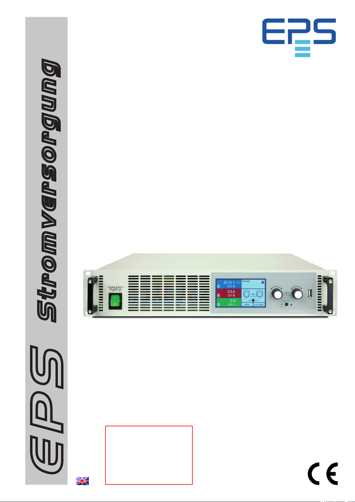
Operating Guide
PSI 9000 2U
DC Laboratory Power Supply
Stromversorgung
Attention! This document is only
valid for devices with rmware
“KE: 2.17” (standard version)
resp. “KE: 2.04” (GPIB, 3W)
and “HMI: 2.10” and “DR: 1.6.5”
or higher. For availability of up-
EPS
dates for your device check our
website or contact us.
Doc ID: PSI92UTEN
Revision: 04
Date: 06/2017
Page 2

Page 3

TABLE OF CONTENTS
GENERAL
1
1.1 About this document ...................................... 5
1.1.1 Retention and use .......................................... 5
1.1.2 Copyright ........................................................5
1.1.3 Validity ............................................................5
1.1.4 Symbols and warnings ..................................5
1.2 Warranty .........................................................5
1.3 Limitation of liability ........................................ 5
1.4 Disposal of equipment ...................................6
1.5 Product key ....................................................6
1.6 Intended usage ..............................................6
1.7 Safety .............................................................7
1.7.1 Safety notices ................................................. 7
1.7.2 Responsibility of the user...............................7
1.7.3 Responsibility of the operator ....................... 8
1.7.4 User requirements .........................................8
1.7.5 Alarm signals .................................................. 9
1.8 Technical Data ...............................................9
1.8.1 Approved operating conditions ...................... 9
1.8.2 General technical data ................................... 9
1.8.3 Specic technical data .................................10
1.8.4 Views ............................................................22
1.8.5 Control elements ..........................................25
1.9 Construction and function ............................26
1.9.1 General description ......................................26
1.9.2 Block diagram ..............................................26
1.9.3 Scope of delivery .........................................27
1.9.4 Accessories ..................................................27
1.9.5 Options .........................................................27
1.9.6 The control panel (HMI) ...............................28
1.9.7 USB port (rear side) .....................................31
1.9.8 Interface module slot ...................................31
1.9.9 Analog interface ...........................................31
1.9.10 Share Bus-Connection ................................32
1.9.11 Sense connector (remote sensing) .............32
1.9.12 Master-Slave bus .........................................32
1.9.13 GPIB port (optional) .....................................32
INSTALLATION & COMMISSIONING
2
2.1 Transport and storage .................................33
2.1.1 Transport ......................................................33
2.1.2 Packaging ....................................................33
2.1.3 Storage .........................................................33
2.2 Unpacking and visual check ........................33
2.3 Installation ....................................................33
2.3.1 Safety procedures before installation and
use ................................................................33
2.3.2 Preparation ...................................................34
2.3.3 Installing the device .....................................34
2.3.4 Connection to AC supply .............................35
2.3.5 Connection to DC loads ...............................35
2.3.6 Grounding of the DC output ........................36
PSI 9000 2U Series
2.3.7 Connection of remote sensing ....................37
2.3.8 Installation of an interface module ...............38
2.3.9 Connecting the analog interface .................38
2.3.10 Connecting the “Share” bus ........................39
2.3.11 Connecting the USB port (rear side) ...........39
2.3.12 Initial commission .........................................39
2.3.13 Commission after a rmware update or a
long period of non-use .................................39
OPERATION AND APPLICATION
3
3.1 Personal safety ............................................40
3.2 Operating modes .........................................40
3.2.1 Voltage regulation / Constant voltage .........40
3.2.2 Current regulation / constant current / current
limiting ..........................................................41
3.2.3 Power regulation / constant power / power
limiting ..........................................................41
3.2.4 Internal resistance regulation ......................41
3.3 Alarm conditions ..........................................42
3.3.1 Power Fail ...................................................42
3.3.2 Overtemperature ..........................................42
3.3.3 Overvoltage protection.................................42
3.3.4 Overcurrent protection .................................42
3.3.5 Overpower protection ..................................42
3.4 Manual operation .........................................43
3.4.1 Switching on the device ...............................43
3.4.2 Switching off the device ...............................43
3.4.3 Conguration via MENU ..............................43
3.4.4 Adjustment limits (Limits) .............................52
3.4.5 Changing the operating mode .....................52
3.4.6 Manual adjustment of set values .................53
3.4.7 Switching the main screen view ..................53
3.4.8 The meter bars .............................................54
3.4.9 Switching the DC output on or off ................54
3.4.10 Recording to USB stick (logging) ................55
3.5 Remote control .............................................56
3.5.1 General .........................................................56
3.5.2 Control locations ..........................................56
3.5.3 Remote control via a digital interface ..........56
3.5.4 Remote control via the analog interface
(AI) ................................................................57
3.6 Alarms and monitoring .................................61
3.6.1 Denition of terms ........................................61
3.6.2 Device alarm and event handling ................61
3.7 Control panel (HMI) lock ..............................63
3.8 Limits lock .....................................................64
3.9 Loading and saving a user prole ...............64
3.10 The function generator.................................65
3.10.1 Introduction...................................................65
3.10.2 General .........................................................65
3.10.3 Method of operation .....................................66
3.10.4 Manual operation .........................................66
EPS Stromversorgung GmbH
Alter Postweg 101 • 86159 Augsburg
Germany
Fon: +49 821 / 570451-0
Fax: +49 821 / 570451-25
www.eps-germany.de
Page 3
Page 4

3.10.5 Sine wave function .......................................67
3.10.6 Triangular function .......................................67
3.10.7 Rectangular function ....................................68
3.10.8 Trapezoidal function .....................................69
3.10.9 DIN 40839 function ......................................69
3.10.10 Arbitrary function ..........................................70
3.10.11 Ramp Function .............................................74
3.10.12 UI and IU table functions (XY table) ............74
3.10.13 PV table function (photovoltaics) .................76
3.10.14 FC table function (fuel cell) ..........................77
3.10.15 Remote control of the function generator....79
3.11 Other applications ........................................80
3.11.1 Parallel operation in master-slave mode
(MS) ..............................................................80
3.11.2 Series connection ........................................83
3.11.3 Operation as battery charger .......................83
3.11.4 Two quadrant operation (2QO) ...................84
SERVICE AND MAINTENANCE
4
4.1 Maintenance / cleaning ................................86
4.2 Fault nding / diagnosis / repair...................86
4.2.1 Replacing a defect mains fuse ....................86
4.2.2 Firmware updates ........................................86
4.3 Calibration ....................................................87
4.3.1 Preface .........................................................87
4.3.2 Preparation ...................................................87
4.3.3 Calibration procedure ..................................87
PSI 9000 2U Series
CONTACT AND SUPPORT
5
5.1 Repairs .........................................................89
5.2 Contact options ............................................89
EPS Stromversorgung GmbH
Alter Postweg 101 • 86159 Augsburg
Germany
Fon: +49 821 / 570451-0
Fax: +49 821 / 570451-25
www.eps-germany.de
Page 4
Page 5
PSI 9000 2U Series
1. General
1.1 About this document
1.1.1 Retention and use
This document is to be kept in the vicinity of the equipment for future reference and explanation of the operation of
the device. This document is to be delivered and kept with the equipment in case of change of location and/or user.
1.1.2 Copyright
Reprinting, copying, also partially, usage for other purposes as foreseen of this manual are forbidden and breach
may lead to legal process.
1.1.3 Validity
This manual is valid for the following equipment with TFT display panel, including derived variants.
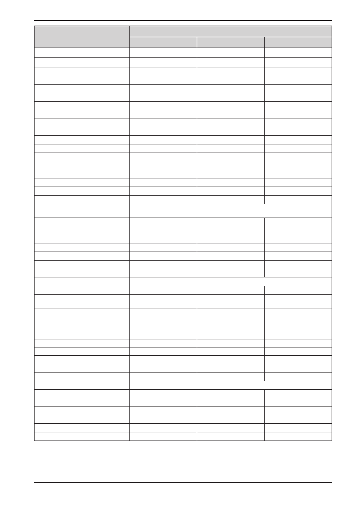
Model Article nr. std. Article nr. HS Model Article nr. std. Article nr. HS
PSI 9080-40 2U 06230304 06730304 PSI 9750-06 2U 06230313 06730313
PSI 9200-15 2U 06230305 06730305 PSI 9080-120 2U 06230314 06730314
PSI 9360-10 2U 06230306 06730306 PSI 9200-50 2U 06230315 06730315
PSI 9500-06 2U 06230307 06730307 PSI 9360-30 2U 06230316 06730316
PSI 9750-04 2U 06230308 06730308 PSI 9500-20 2U 06230317 06730317
PSI 9080-60 2U 06230309 06730309 PSI 9750-12 2U 06230318 06730318
PSI 9200-25 2U 06230310 06730310 PSI 9040-40 2U 06230319 06730319
PSI 9360-15 2U 06230311 06730311 PSI 9040-60 2U 06230320 06730320
PSI 9500-10 2U 06230312 06730312 PSI 9040-120 2U 06230321 06730321
Changes and modications for special models will be listed in a separate document.
1.1.4 Symbols and warnings
Warning and safety notices as well as general notices in this document are shown in a box with a symbol as follows:
Symbol for a life threatening danger
Symbol for general safety notices (instructions and damage protection bans) or important information for operation
Symbol for general notices
1.2 Warranty
EPS Stromversorgung guarantees the functional competence of the applied technology and the stated performance
parameters. The warranty period begins with the delivery of free from defects equipment.
Terms of guarantee are included in the general terms and conditions (TOS) of EPS Stromversorgung.
1.3 Limitation of liability
All statements and instructions in this manual are based on current norms and regulations, up-to-date technology
and our long term knowledge and experience. The manufacturer accepts no liability for losses due to:
• Usage for purposes other than designed
• Use by untrained personnel
• Rebuilding by the customer
• Technical changes
• Use of not authorized spare parts
The actual delivered device(s) may differ from the explanations and diagrams given here due to latest technical
changes or due to customized models with the inclusion of additionally ordered options.
EPS Stromversorgung GmbH
Alter Postweg 101 • 86159 Augsburg
Germany
Fon: +49 821 / 570451-0
Fax: +49 821 / 570451-25
www.eps-germany.de
Page 5
Page 6
PSI 9000 2U Series
1.4 Disposal of equipment
A piece of equipment which is intended for disposal must, according to European laws and regulations (ElektroG,
WEEE) be returned to the manufacturer for scrapping, unless the person operating the piece of equipment or another, delegated person is conducting the disposal. Our equipment falls under these regulations and is accordingly
marked with the following symbol:
1.5 Product key
Decoding of the product description on the label, using an example:
PSI 9 080 - 40 2U zzz
Field for identication of installed options and/or special models
S01...S0x = Special version
HS = High Speed option installed
3W = Option 3W installed (GPIB port instead of interface slot)
Construction (not always given)
2U = 19" rack enclosure with 2U of height
Maximum current of the device in Ampere
Maximum voltage of the device in Volt
Series : 8 = Series 8000 or 800, 9 = Series 9000
Type identication:
PSI = Power Supply Intelligent, always programmable
Special models are always derived from standard models and can vary in input voltage and
current from those given.
1.6 Intended usage
The equipment is intended to be used, if a power supply or battery charger, only as a variable voltage and current
source, or, if an electronic load, only as a variable current sink.
Typical application for a power supply is DC supply to any relevant user, for a battery charger the charging of various battery types and for electronic loads the replacement of an ohmic resistor by an adjustable DC current sink
in order to load relevant voltage and current sources of any type.
• Claims of any sort due to damage caused by non-intended usage will not be accepted.
• All damage caused by non-intended usage is solely the responsibility of the operator.
EPS Stromversorgung GmbH
Alter Postweg 101 • 86159 Augsburg
Germany
Fon: +49 821 / 570451-0
Fax: +49 821 / 570451-25
www.eps-germany.de
Page 6
Page 7
1.7 Safety
1.7.1 Safety notices
Mortal danger - Hazardous voltage
• Electrical equipment operation means that some parts can be under dangerous voltage.
Therefore all parts under voltage must be covered! This basically applies to all models,
though 40 V models according to SELV can not generate hazardous DC voltage.
• All work on connections must be carried out under zero voltage (output not connected
to load) and may only be performed by qualied and informed persons. Improper actions can cause fatal injury as well as serious material damage.
• Never touch cables or connectors directly after unplugging from mains supply as the
danger of electric shock remains.
• Never touch the contacts on DC output terminal directly after switching off the DC output,
because there still can dangerous voltage present, sinking more or less slowly depending on the load! There also can be dangerous potential between negative DC output to
PE or positive DC output to PE due to charged X capacitors.
• The equipment must only be used as intended
• The equipment is only approved for use within the connection limits stated on the product label.
• Do not insert any object, particularly metallic, through the ventilator slots
• Avoid any use of liquids near the equipment. Protect the device from wet, damp and conden-
sation.
• For power supplies and battery chargers: do not connect users, particularly low resistance, to
devices under power; sparking may occur which can cause burns as well as damage to the
equipment and to the user.
• For electronic loads: do not connect power sources to equipment under power, sparking may
occur which can cause burns as well as damage to the equipment and to the source.
• ESD regulations must be applied when plugging interface cards or modules into the relative slot
• Interface cards or modules may only be attached or removed after the device is switched off.
It is not necessary to open the device.
• Do not connect external power sources with reversed polarity to DC input or outputs! The
equipment will be damaged.
• For power supply devices: avoid where possible connecting external power sources to the DC
output, and never those that can generate a higher voltage than the nominal voltage of the device.
• For electronic loads: do not connect a power source to the DC input which can generate a voltage more than 120% of the nominal input voltage of the load. The equipment is not protected
against over voltage and may be irreparably damaged.
• Never insert a network cable which is connected to Ethernet or its components into the masterslave socket on the back side of the device!
• Always congure the various protecting features against overvoltage etc. for sensitive loads to
what the target application requires!
PSI 9000 2U Series
1.7.2 Responsibility of the user
The equipment is in industrial operation. Therefore the operators are governed by the legal safety regulations.
Alongside the warning and safety notices in this manual the relevant safety, accident prevention and environmental
regulations must also be applied. In particular the users of the equipment:
• must be informed of the relevant job safety requirements
• must work to the dened responsibilities for operation, maintenance and cleaning of the equipment
• before starting work must have read and understood the operating manual
• must use the designated and recommended safety equipment.
Furthermore, anyone working with the equipment is responsible for ensuring that the device is at all times techni-
cally t for use.
EPS Stromversorgung GmbH
Alter Postweg 101 • 86159 Augsburg
Germany
Fon: +49 821 / 570451-0
Fax: +49 821 / 570451-25
www.eps-germany.de
Page 7
Page 8
PSI 9000 2U Series
1.7.3 Responsibility of the operator
Operator is any natural or legal person who uses the equipment or delegates the usage to a third party, and is
responsible during its usage for the safety of the user, other personnel or third parties.
The equipment is in industrial operation. Therefore the operators are governed by the legal safety regulations.
Alongside the warning and safety notices in this manual the relevant safety, accident prevention and environmental
regulations must also be applied. In particular the operator has to
• be acquainted with the relevant job safety requirements
• identify other possible dangers arising from the specic usage conditions at the work station via a risk assessment
• introduce the necessary steps in the operating procedures for the local conditions
• regularly control that the operating procedures are current
• update the operating procedures where necessary to reect changes in regulation, standards or operating con-
ditions.
• dene clearly and unambiguously the responsibilities for operation, maintenance and cleaning of the equipment.
• ensure that all employees who use the equipment have read and understood the manual. Furthermore the users
are to be regularly schooled in working with the equipment and the possible dangers.
• provide all personnel who work with the equipment with the designated and recommended safety equipment
Furthermore, the operator is responsible for ensuring that the device is at all times technically t for use.
1.7.4 User requirements
Any activity with equipment of this type may only be performed by persons who are able to work correctly and
reliably and satisfy the requirements of the job.
• Persons whose reaction capability is negatively inuenced by e.g. drugs, alcohol or medication may not operate
the equipment.
• Age or job related regulations valid at the operating site must always be applied.
Danger for unqualied users
Improper operation can cause person or object damage. Only persons who have the necessary
training, knowledge and experience may use the equipment.
Delegated persons are those who have been properly and demonstrably instructed in their tasks and the attendant dangers.
Qualied persons are those who are able through training, knowledge and experience as well as knowledge of
the specic details to carry out all the required tasks, identify dangers and avoid personal and other risks.
EPS Stromversorgung GmbH
Alter Postweg 101 • 86159 Augsburg
Germany
Fon: +49 821 / 570451-0
Fax: +49 821 / 570451-25
www.eps-germany.de
Page 8
Page 9
PSI 9000 2U Series
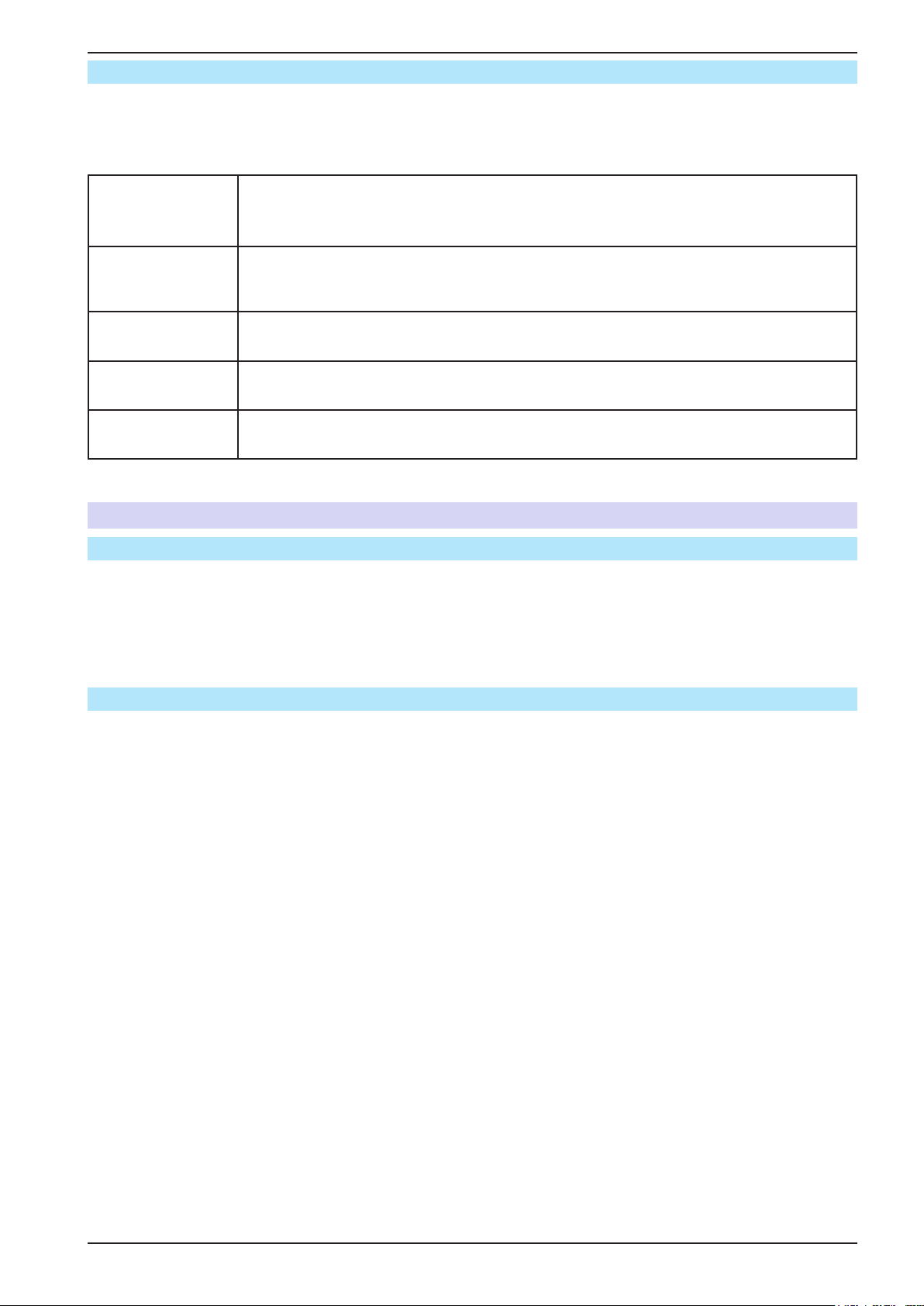
1.7.5 Alarm signals
The equipment offers various possibilities for signalling alarm conditions, however, not for danger situations. The
signals may be optical (on the display as text) acoustic (piezo buzzer) or electronic (pin/status output of an analog
interface). All alarms will cause the device to switch off the DC output.
The meaning of the signals is as follows:
Signal OT
(OverTemperature)
• Overheating of the device
• DC output will be switched off
• Non-critical
Signal OVP
(OverVoltage)
• Overvoltage shutdown of the DC output due to high voltage entering the device or generated by the device itself due to a defect
• Critical! The device and/or the load could be damaged
Signal OCP
(OverCurrent)
Signal OPP
(OverPower)
Signal PF
(Power Fail)
• Shutdown of the DC output due to excess of the preset limit
• Non-critical, protects the load from excessive current consumption
• Shutdown of the DC output due to excess of the preset limit
• Non-critical, protects the load from excessive power consumption
• DC output shutdown due to AC undervoltage or defect in the AC input
• Critical on overvoltage! AC input circuit could be damaged
1.8 Technical Data
1.8.1 Approved operating conditions
• Use only inside dry buildings
• Ambient temperature 0-50°C
• Operational altitude: max. 2000 m above sea level
• Max. 80% relative humidity, non-condensing
1.8.2 General technical data
Display: Colour TFT touch screen with gorilla glass, 4.3”, 480pt x 272pt, capacitive
Controls: 2 rotary knobs with pushbutton functions, 2 pushbutton
The nominal values for the device determine the maximum adjustable ranges.
EPS Stromversorgung GmbH
Alter Postweg 101 • 86159 Augsburg
Germany
Fon: +49 821 / 570451-0
Fax: +49 821 / 570451-25
www.eps-germany.de
Page 9
Page 10

PSI 9000 2U Series
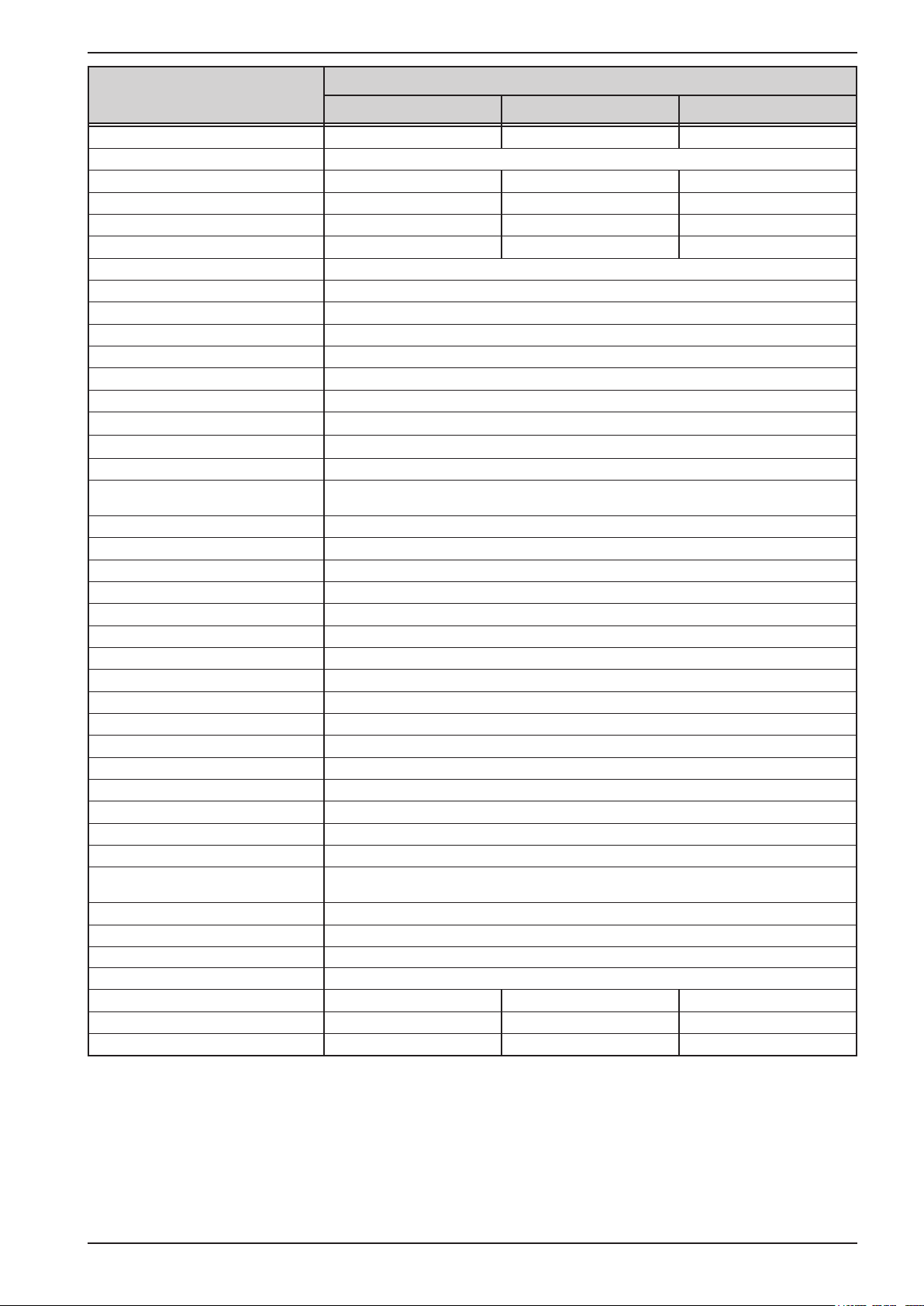
1.8.3 Specic technical data
Model 2U
1000 W
AC Input
Voltage range 90...264 V AC 90...264 V AC 90...264 V AC
Connection 1ph,N,PE 1ph,N,PE 1ph,N,PE
Frequency 45-65 Hz 45-65 Hz 45-65 Hz
Fusing T16 A T16 A T16 A
Leak current < 3.5 mA < 3.5 mA < 3.5 mA
Power factor ~ 0.99 ~ 0.99 ~ 0.99
DC Output
Max. output voltage U
Max. output current I
Max. output power P
Overvoltage protection range 0...44 V 0...88 V 0...220 V
Overcurrent protection range 0...44 A 0...44 A 0...16.5 A
Overpower protection range 0…1100 W 0…1100 W 0…1100 W
Output capacitance (std. model) 5440 μF 5440 μF 800 μF
Output capacitance (HS model) 86 μF 86 μF 40 μF
Temperature coefcient for set
values Δ/K
Voltage regulation
Adjustment range 0...40 V 0...80 V 0...200 V
Accuracy
(1
(at 23 ± 5°C) < 0.1% U
Line regulation at ±10% ΔU
Load regulation at 0...100% load < 0.05% U
Rise time 10...90% Max. 30 ms Max. 30 ms Max. 30 ms
Settling time after load step < 1.5 ms < 1.5 ms < 1.5 ms
Display: Resolution See section „1.9.6.4. Resolution of the displayed values“
Display: Accuracy
(2
Ripple
Remote sensing compensation Max. 5% U
Output voltage fall time (at no load)
after switching DC output off
Current regulation
Adjustment range 0...40 A 0...40 A 0...15 A
Accuracy
(1
(at 23 ± 5°C) < 0.2% I
Line regulation at ±10% ΔU
Load regulation at 0...100% ΔU
(2
Ripple
Display: Resolution See section „1.9.6.4. Resolution of the displayed values“
Display: Accuracy
Power regulation
Adjustment range 0…1000 W 0…1000 W 0…1000 W
Accuracy
(1
(at 23 ± 5°C) < 1% P
Line regulation at ±10% ΔU
Load reg. at 10-90% ΔU
Max
Max
Max
AC
(3
AC
(3
AC
* ΔI
OUT
PSI 9040-40 PSI 9080-40 PSI 9200-15
40 V 80 V 200 V
40 A 40 A 15 A
1000 W 1000 W 1000 W
Voltage / current: 100 ppm
Nom
< 0.02% U
≤ 0.2% U
Nom
Nom
Nom
< 114 mVPP
< 8 mV
RMS
Nom
- -
Nom
OUT
OUT
< 0.05% I
< 0.15% I
< 3.7 mA
≤ 0.2% I
< 0.05% P
< 0.75% P
Nom
Nom
RMS
Nom
Nom
Nom
Nom
< 0.1% U
Nom
< 0.02% U
< 0.05% U
≤ 0.2% U
Nom
< 114 mVPP
< 8 mV
RMS
Max. 5% U
< 0.2% I
< 0.05% I
< 0.15% I
< 3.7 mA
≤ 0.2% I
< 1% P
Nom
Nom
Nom
RMS
Nom
Nom
< 0.05% P
< 0.75% P
Nom
Nom
Nom
Nom
Nom
< 0.1% U
< 0.02% U
< 0.05% U
≤ 0.2% U
< 164 mVPP
< 34 mV
Max. 5% U
Down from 100% to
<60 V: less than 10 s
< 0.2% I
< 0.05% I
< 0.15% I
< 2.2 mA
≤ 0.2% I
< 1% P
Nom
< 0.05% P
< 0.75% P
Nom
Nom
Nom
Nom
RMS
Nom
Nom
Nom
Nom
RMS
Nom
Nom
Nom
(1 Related to the nominal values, the accuracy denes the maximum deviation between an adjusted values and the true (actual) value.
Example: a 80 V model has min. 0.1% voltage accuracy, that is 80 mV. When adjusting the voltage to 5 V, the actual value is allowed to differ max. 80 mV, which
means it might be between 4.92 V and 5.08 V.
(2 RMS value: LF 0...300 kHz, PP value: HF 0...20MHz
(3 The display error adds to the error of the related actual value on the DC output
EPS Stromversorgung GmbH
Alter Postweg 101 • 86159 Augsburg
Germany
Fon: +49 821 / 570451-0
Fax: +49 821 / 570451-25
www.eps-germany.de
Page 10
Page 11
PSI 9000 2U Series
Model 2U
1000 W
Power regulation
Display: Resolution See section „1.9.6.4. Resolution of the displayed values“
Display: Accuracy
Efciency
(5
Internal resistance regulation
Adjustment range 0...30 Ω 0...60 Ω 0...400 Ω
Accuracy
(1
Display: Resolution See section „1.9.6.4. Resolution of the displayed values“
Analog interface
Set value inputs U, I, P, R
Actual value output U, I
Control signals DC on/off, remote control on/off, resistance mode on/off
Status signals CV, OVP, OT
Galvanic isolation to the device Max. 1500 V DC
Sample rate of inputs & outputs 500 Hz
Insulation
Output (DC) to enclosure (PE)
Input (AC) to output (DC) Max. 2500 V, short-term
Miscellaneous
Cooling Temperature controlled fans, front inlet, rear exhaust
Ambient temperature 0..50°C
Storage temperature -20...70°C
Humidity < 80%, not condensing
Standards EN 61010, EN 61326
Overvoltage category 2
Protection class 1
Pollution degree 2
Operational altitude < 2000 m
Digital interfaces
Featured 1x USB-B for communication, 1x USB-A for functions, 1x GPIB (only with option 3W)
Slot (standard version) optional: CAN, CANopen, Probus, Pronet, RS232, Ethernet, ModBus TCP
Galvanic isolation from device Max. 1500 V DC
Terminals
Rear side
Front side USB-A
Dimensions
Enclosure (WxHxD) 19“ x 2U x 463 mm
Total (WxHxD) 483 x 88 x min. 535 mm (depending on DC out terminal type)
Weight ~ 12 kg ~ 12 kg ~ 12 kg
Article number of std. model
Article number of HS model
(2
(3
(4
PSI 9040-40 PSI 9080-40 PSI 9200-15
≤ 0.8% P
Nom
~ 92% ~ 92% ~ 93%
≤ 2% of max. resistance ± 0.3% of maximum current
DC minus: permanent max. ±400 V
DC plus: permanent max. ±400V + output voltage
Share Bus, DC output, AC input, remote sensing, analog interface, USB-B, masterslave bus, Interface module slot
(4
06230319 06230304 06230305
06730319 06730304 06730305
≤ 0.8% P
Nom
≤ 0.8% P
Nom
(1 Related to the nominal values, the accuracy denes the maximum deviation between an adjusted values and the true (actual) value.
(2 The display error adds to the error of the related actual value on the DC output
(3 For technical specications of the analog interface see „3.5.4.4 Analog interface specication“ on page 58
(4 Article number of the base version, devices with options will have a different number
(5 Typical value at 100% output voltage and 100% power
EPS Stromversorgung GmbH
Alter Postweg 101 • 86159 Augsburg
Germany
Fon: +49 821 / 570451-0
Fax: +49 821 / 570451-25
www.eps-germany.de
Page 11
Page 12

PSI 9000 2U Series
Model 2U
1000 W
AC Input
Voltage range 90...264 V AC 90...264 V AC 90...264 V AC
Connection 1ph,N,PE 1ph,N,PE 1ph,N,PE
Frequency 45-65 Hz 45-65 Hz 45-65 Hz
Fusing T16 A T16 A T16 A
Leak current < 3.5 mA < 3.5 mA < 3.5 mA
Power factor ~ 0.99 ~ 0.99 ~ 0.99
DC Output
Max. output voltage U
Max. output current I
Max. output power P
Overvoltage protection range 0...396 V 0...550 V 0...825 V
Overcurrent protection range 0...11 A 0...6.6 A 0...4.4 A
Overpower protection range 0…1100 W 0…1100 W 0…1100 W
Output capacitance (std. model) 330 μF 120 μF 40 μF
Output capacitance (HS model) 20 μF 15 μF 9 μF
Temperature coefcient for set
values Δ/K
Voltage regulation
Adjustment range 0...360 V 0...500 V 0...750 V
Accuracy
(1
(at 23 ± 5°C) < 0.1% U
Line regulation at ±10% ΔU
Load regulation at 0...100% load < 0.05% U
Rise time 10...90% Max. 30 ms Max. 30 ms Max. 30 ms
Settling time after load step < 1.5 ms < 1.5 ms < 1.5 ms
Display: Resolution See section „1.9.6.4. Resolution of the displayed values“
Display: Accuracy
(2
Ripple
Remote sensing compensation Max. 5% U
Output voltage fall time (at no load)
after switching DC output off
Current regulation
Adjustment range 0...10 A 0...6 A 0...4 A
Accuracy
(1
(at 23 ± 5°C) < 0.2% I
Line regulation at ±10% ΔU
Load regulation at 0...100% ΔU
(2
Ripple
Display: Resolution See section „1.9.6.4. Resolution of the displayed values“
Display: Accuracy
Power regulation
Adjustment range 0…1000 W 0…1000 W 0…1000 W
Accuracy
(1
(at 23 ± 5°C) < 1% P
Line regulation at ±10% ΔU
Load reg. at 10-90% ΔU
Max
Max
Max
AC
(3
AC
(3
AC
* ΔI
OUT
PSI 9360-10 PSI 9500-06 PSI 9750-04
360 V 500 V 750 V
10 A 6 A 4 A
1000 W 1000 W 1000 W
Voltage / current: 100 ppm
Nom
< 0.02% U
≤ 0.2% U
Nom
Nom
Nom
< 210 mVPP
< 59 mV
RMS
Nom
Down from 100% to <60 V: less than 10 s
Nom
OUT
OUT
< 0.05% I
< 0.15% I
< 1.6 mA
≤ 0.2% I
< 0.05% P
< 0.75% P
Nom
Nom
RMS
Nom
Nom
Nom
Nom
< 0.1% U
Nom
< 0.02% U
< 0.05% U
≤ 0.2% U
Nom
< 190 mVPP
< 48 mV
RMS
Max. 5% U
< 0.2% I
< 0.05% I
< 0.15% I
< 0.5 mA
≤ 0.2% I
< 1% P
Nom
Nom
Nom
RMS
Nom
Nom
< 0.05% P
< 0.75% P
Nom
Nom
Nom
Nom
Nom
< 0.1% U
Nom
< 0.02% U
< 0.05% U
≤ 0.2% U
Nom
< 212 mVPP
< 60 mV
RMS
Max. 5% U
< 0.2% I
Nom
< 0.05% I
< 0.15% I
< 0.3 mA
≤ 0.2% I
< 1% P
RMS
Nom
Nom
< 0.05% P
< 0.75% P
Nom
Nom
Nom
Nom
Nom
Nom
Nom
(1 Related to the nominal values, the accuracy denes the maximum deviation between an adjusted values and the true (actual) value.
Example: a 80 V model has min. 0.1% voltage accuracy, that is 80 mV. When adjusting the voltage to 5 V, the actual value is allowed to differ max. 80 mV, which
means it might be between 4.92 V and 5.08 V.
(2 RMS value: LF 0...300 kHz, PP value: HF 0...20MHz
(3 The display error adds to the error of the related actual value on the DC output
EPS Stromversorgung GmbH
Alter Postweg 101 • 86159 Augsburg
Germany
Fon: +49 821 / 570451-0
Fax: +49 821 / 570451-25
www.eps-germany.de
Page 12
Page 13
PSI 9000 2U Series
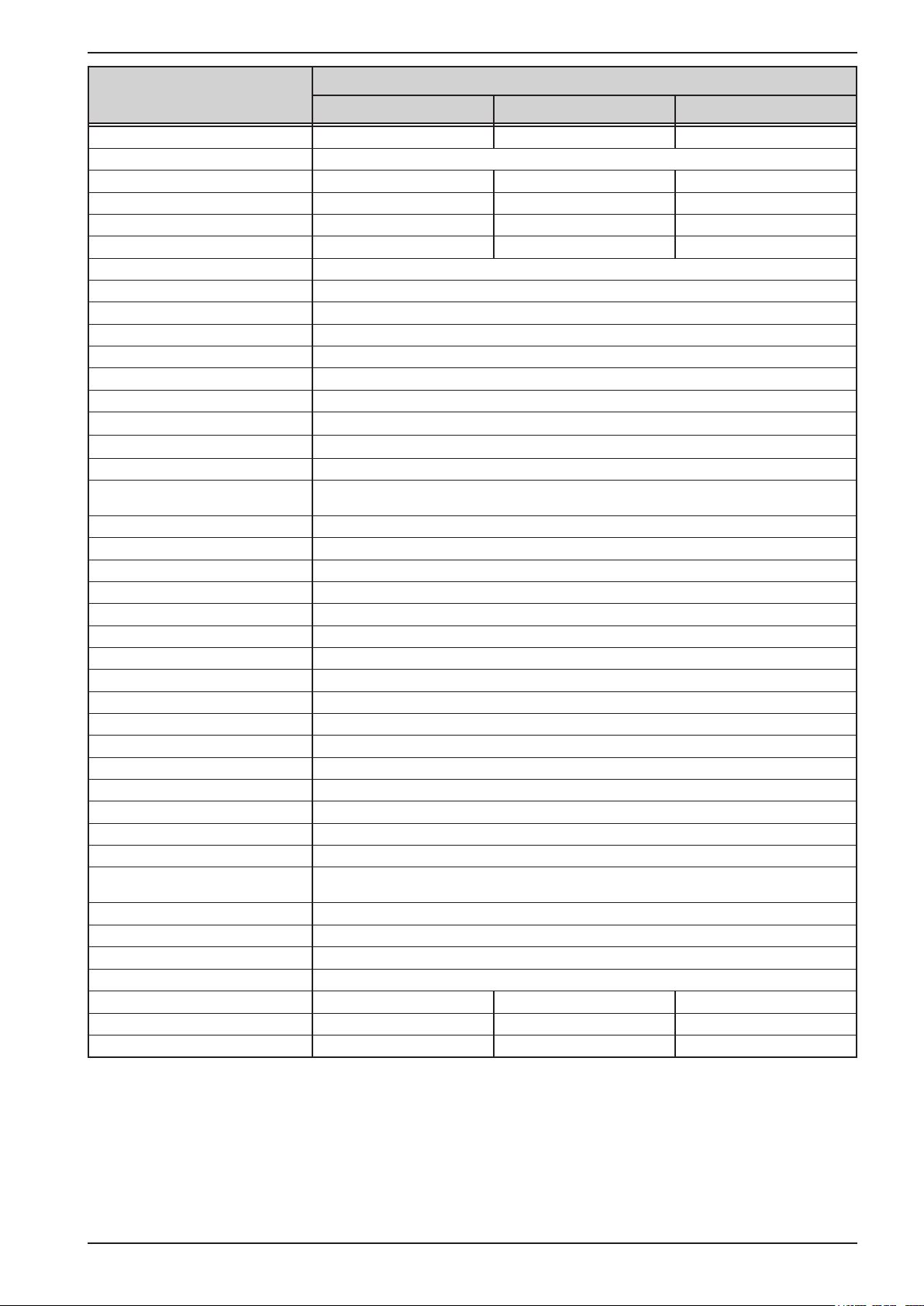
Model 2U
1000 W
Power regulation
Display: Resolution See section „1.9.6.4. Resolution of the displayed values“
Display: Accuracy
Efciency
(5
Internal resistance regulation
Adjustment range 0...1080 Ω 0...2500 Ω 0...5625 Ω
Accuracy
(1
Display: Resolution See section „1.9.6.4. Resolution of the displayed values“
Analog interface
Set value inputs U, I, P, R
Actual value output U, I
Control signals DC on/off, remote control on/off, resistance mode on/off
Status signals CV, OVP, OT
Galvanic isolation to the device Max. 1500 V DC
Sample rate of inputs & outputs 500 Hz
Insulation
Output (DC) to enclosure (PE)
Input (AC) to output (DC) Max. 2500 V, short-term
Miscellaneous
Cooling Temperature controlled fans, front inlet, rear exhaust
Ambient temperature 0..50°C
Storage temperature -20...70°C
Humidity < 80%, not condensing
Standards EN 61010, EN 61326
Overvoltage category 2
Protection class 1
Pollution degree 2
Operational altitude < 2000 m
Digital interfaces
Featured 1x USB-B for communication, 1x USB-A for functions, 1x GPIB (only with option 3W)
Slot (standard version) optional: CAN, CANopen, Probus, Pronet, RS232, Ethernet, ModBus TCP
Galvanic isolation from device Max. 1500 V DC
Terminals
Rear side
Front side USB-A
Dimensions
Enclosure (WxHxD) 19“ x 2U x 463 mm
Total (WxHxD) 483 x 88 x min. 535 mm (depending on DC out terminal type)
Weight ~ 12 kg ~ 12 kg ~ 12 kg
Article number of std. model (406230306 06230307 06230308
Article number of HS model
(2
(3
PSI 9360-10 PSI 9500-06 PSI 9750-04
≤ 0.8% P
Nom
~ 93% ~ 93% ~ 93%
≤ 2% of max. resistance ± 0.3% of maximum current
DC minus: permanent max. ±400 V
DC plus: permanent max. ±400V + output voltage
Share Bus, DC output, AC input, remote sensing, analog interface, USB-B, masterslave bus, Interface module slot
(4
06730306 06730307 06730308
≤ 0.8% P
Nom
≤ 0.8% P
Nom
(1 Related to the nominal values, the accuracy denes the maximum deviation between an adjusted values and the true (actual) value.
(2 The display error adds to the error of the related actual value on the DC output
(3 For technical specications of the analog interface see „3.5.4.4 Analog interface specication“ on page 58
(4 Article number of the base version, devices with options will have a different number
(5 Typical value at 100% output voltage and 100% power
EPS Stromversorgung GmbH
Alter Postweg 101 • 86159 Augsburg
Germany
Fon: +49 821 / 570451-0
Fax: +49 821 / 570451-25
www.eps-germany.de
Page 13
Page 14
PSI 9000 2U Series
Model 2U
1500 W
AC Input
Voltage range 90...264 V AC 90...264 V AC 90...264 V AC
- with additional derating 90...150 V AC 90...150 V AC 90...150 V AC
Connection 1ph,N,PE 1ph,N,PE 1ph,N,PE
Frequency 45-65 Hz 45-65 Hz 45-65 Hz
Fusing T16 A T16 A T16 A
Leak current < 3.5 mA < 3.5 mA < 3.5 mA
Power factor ~ 0.99 ~ 0.99 ~ 0.99
DC Output
Max. output voltage U
Max. output current I
Max. output power P
Max. output power P
Overvoltage protection range 0...44 V 0...88 V 0...220 V
Overcurrent protection range 0...66 A 0...66 A 0...27.5 A
Overpower protection range 0…1650 W 0…1650 W 0…1650 W
Output capacitance (std. model) 5440 μF 5440 μF 800 μF
Output capacitance (HS model) 86 μF 86 μF 40 μF
Temperature coefcient for set
values Δ/K
Voltage regulation
Adjustment range 0..40 V 0...80 V 0...200 V
Accuracy
(1
(at 23 ± 5°C) < 0.1% U
Line regulation at ±10% ΔU
Load regulation at 0...100% load < 0.05% U
Rise time 10...90% Max. 30 ms Max. 30 ms Max. 30 ms
Settling time after load step < 1.5 ms < 1.5 ms < 1.5 ms
Display: Resolution See section „1.9.6.4. Resolution of the displayed values“
Display: Accuracy
(2
Ripple
Remote sensing compensation Max. 5% U
Output voltage fall time (at no load)
after switching DC output off
Current regulation
Adjustment range 0...60 A 0...60 A 0...25 A
Accuracy
(1
(at 23 ± 5°C) < 0.2% I
Line regulation at ±10% ΔU
Load regulation at 0...100% ΔU
(2
Ripple
Display: Resolution See section „1.9.6.4. Resolution of the displayed values“
Display: Accuracy
Power regulation
Adjustment range 0…1500 W 0…1500 W 0…1500 W
Accuracy
(1
(at 23 ± 5°C) < 1% P
Line regulation at ±10% ΔU
Load reg. at 10-90% ΔU
Max
Max
Max
with derating 1000 W 1000 W 1000 W
Max
AC
(3
AC
(3
AC
* ΔI
OUT
PSI 9040-60 PSI 9080-60 PSI 9200-25
40 V 80 V 200 V
60 A 60 A 25 A
1500 W 1500 W 1500 W
Voltage / current: 100 ppm
Nom
< 0.02% U
≤ 0.2% U
Nom
Nom
Nom
< 114 mVPP
< 8 mV
RMS
Nom
- -
Nom
OUT
OUT
< 0.05% I
< 0.15% I
< 5.6 mA
≤ 0.2% I
< 0.05% P
< 0.75% P
Nom
Nom
RMS
Nom
Nom
Nom
Nom
< 0.1% U
Nom
< 0.02% U
< 0.05% U
≤ 0.2% U
Nom
< 114 mVPP
< 8 mV
RMS
Max. 5% U
< 0.2% I
< 0.05% I
< 0.15% I
< 5.6 mA
≤ 0.2% I
< 1% P
Nom
Nom
Nom
RMS
Nom
Nom
< 0.05% P
< 0.75% P
Nom
Nom
Nom
Nom
Nom
< 0.1% U
Nom
< 0.02% U
< 0.05% U
≤ 0.2% U
Nom
< 164 mVPP
< 34 mV
RMS
Max. 5% U
Down from 100% to
<60 V: less than 10 s
< 0.2% I
Nom
< 0.05% I
< 0.15% I
< 1.3 mA
≤ 0.2% I
< 1% P
RMS
Nom
Nom
< 0.05% P
< 0.75% P
Nom
Nom
Nom
Nom
Nom
Nom
Nom
(1 Related to the nominal values, the accuracy denes the maximum deviation between an adjusted values and the true (actual) value.
Example: a 80 V model has min. 0.1% voltage accuracy, that is 80 mV. When adjusting the voltage to 5 V, the actual value is allowed to differ max. 80 mV, which
means it might be between 4.92 V and 5.08 V.
(2 RMS value: LF 0...300 kHz, PP value: HF 0...20MHz
(3 The display error adds to the error of the related actual value on the DC output
EPS Stromversorgung GmbH
Alter Postweg 101 • 86159 Augsburg
Germany
Fon: +49 821 / 570451-0
Fax: +49 821 / 570451-25
www.eps-germany.de
Page 14
Page 15

PSI 9000 2U Series
Model 2U
1500 W
Power regulation
Display: Resolution See section „1.9.6.4. Resolution of the displayed values“
Display: Accuracy
Efciency
(5
Internal resistance regulation
Adjustment range 0...20 Ω 0...40 Ω 0...240 Ω
Accuracy
(1
Display: Resolution See section „1.9.6.4. Resolution of the displayed values“
Analog interface
Set value inputs U, I, P, R
Actual value output U, I
Control signals DC on/off, remote control on/off, resistance mode on/off
Status signals CV, OVP, OT
Galvanic isolation to the device Max. 1500 V DC
Sample rate of inputs & outputs 500 Hz
Insulation
Output (DC) to enclosure (PE)
Input (AC) to output (DC) Max. 2500 V, short-term
Miscellaneous
Cooling Temperature controlled fans, front inlet, rear exhaust
Ambient temperature 0..50°C
Storage temperature -20...70°C
Humidity < 80%, not condensing
Standards EN 61010, EN 61326
Overvoltage category 2
Protection class 1
Pollution degree 2
Operational altitude < 2000 m
Digital interfaces
Featured 1x USB-B for communication, 1x USB-A for functions, 1x GPIB (only with option 3W)
Slot (standard version) optional: CAN, CANopen, Probus, Pronet, RS232, Ethernet, ModBus TCP
Galvanic isolation from device Max. 1500 V DC
Terminals
Rear side
Front side USB-A
Dimensions
Enclosure (WxHxD) 19“ x 2U x 463 mm
Total (WxHxD) 483 x 88 x min. 535 mm (depending on DC out terminal type)
Weight ~ 12 kg ~ 12 kg ~ 12 kg
Article number of std. model (406230320 06230309 06230310
Article number of HS model
(2
(4
PSI 9040-60 PSI 9080-60 PSI 9200-25
≤ 0.8% P
Nom
~ 92% ~ 92% ~ 93%
≤ 2% of max. resistance ± 0.3% of maximum current
DC minus: permanent max. ±400 V
DC plus: permanent max. ±400V + output voltage
Share Bus, DC output, AC input, remote sensing, analog interface, USB-B, masterslave bus, Interface module slot
(4
06730320 06730309 06730310
≤ 0.8% P
Nom
≤ 0.7% P
Nom
(1 Related to the nominal values, the accuracy denes the maximum deviation between an adjusted values and the true (actual) value.
(2 The display error adds to the error of the related actual value on the DC output
(3 For technical specications of the analog interface see „3.5.4.4 Analog interface specication“ on page 58
(4 Article number of the base version, devices with options will have a different number
(5 Typical value at 100% output voltage and 100% power
EPS Stromversorgung GmbH
Alter Postweg 101 • 86159 Augsburg
Germany
Fon: +49 821 / 570451-0
Fax: +49 821 / 570451-25
www.eps-germany.de
Page 15
Page 16

PSI 9000 2U Series
Model 2U
1500 W
AC Input
Voltage range 90...264 V AC 90...264 V AC 90...264 V AC
- with additional derating 90...150 V AC 90...150 V AC 90...150 V AC
Connection 1ph,N,PE 1ph,N,PE 1ph,N,PE
Frequency 45-65 Hz 45-65 Hz 45-65 Hz
Fusing T16 A T16 A T16 A
Leak current < 3.5 mA < 3.5 mA < 3.5 mA
Power factor ~ 0.99 ~ 0.99 ~ 0.99
DC Output
Max. output voltage U
Max. output current I
Max. output power P
Max. output power P
Overvoltage protection range 0...396 V 0...550 V 0...825 V
Overcurrent protection range 0...16.5 A 0...11 A 0...6.6 A
Overpower protection range 0…1650 W 0…1650 W 0…1650 W
Output capacitance (std. model) 330 μF 120 μF 40 μF
Output capacitance (HS model) 20 μF 15 μF 9 μF
Temperature coefcient for set
values Δ/K
Voltage regulation
Adjustment range 0...360 V 0...500 V 0...750 V
Accuracy
(1
(at 23 ± 5°C) < 0.1% U
Line regulation at ±10% ΔU
Load regulation at 0...100% load < 0.05% U
Rise time 10...90% Max. 30 ms Max. 30 ms Max. 30 ms
Settling time after load step < 1.5 ms < 1.5 ms < 1.5 ms
Display: Resolution See section „1.9.6.4. Resolution of the displayed values“
Display: Accuracy
(2
Ripple
Remote sensing compensation Max. 5% U
Output voltage fall time (at no load)
after switching DC output off
Current regulation
Adjustment range 0...15 A 0...10 A 0...6 A
Accuracy
(1
(at 23 ± 5°C) < 0.2% I
Line regulation at ±10% ΔU
Load regulation at 0...100% ΔU
(2
Ripple
Display: Resolution See section „1.9.6.4. Resolution of the displayed values“
Display: Accuracy
Power regulation
Adjustment range 0…1500 W 0…1500 W 0…1500 W
Accuracy
(1
(at 23 ± 5°C) < 1% P
Line regulation at ±10% ΔU
Load reg. at 10-90% ΔU
Max
Max
Max
with derating 1000 W 1000 W 1000 W
Max
AC
(3
AC
(3
AC
* ΔI
OUT
PSI 9360-15 PSI 9500-10 PSI 9750-06
360 V 500 V 750 V
15 A 10 A 6 A
1500 W 1500 W 1500 W
Voltage / current: 100 ppm
Nom
< 0.02% U
≤ 0.2% U
Nom
Nom
Nom
< 210 mVPP
< 59 mV
RMS
Nom
Down from 100% to <60 V: less than 10 s
Nom
OUT
OUT
< 0.05% I
< 0.15% I
< 2.4 mA
≤ 0.2% I
< 0.05% P
< 0.75% P
Nom
Nom
RMS
Nom
Nom
Nom
Nom
< 0.1% U
Nom
< 0.02% U
< 0.05% U
≤ 0.2% U
Nom
< 190 mVPP
< 48 mV
RMS
Max. 5% U
< 0.2% I
< 0.05% I
< 0.15% I
< 0.7 mA
≤ 0.2% I
< 1% P
Nom
Nom
Nom
RMS
Nom
Nom
< 0.05% P
< 0.75% P
Nom
Nom
Nom
Nom
Nom
< 0.1% U
Nom
< 0.02% U
< 0.05% U
≤ 0.2% U
Nom
< 212 mVPP
< 60 mV
RMS
Max. 5% U
< 0.2% I
Nom
< 0.05% I
< 0.15% I
< 0.5 mA
≤ 0.2% I
< 1% P
RMS
Nom
Nom
< 0.05% P
< 0.75% P
Nom
Nom
Nom
Nom
Nom
Nom
Nom
(1 Related to the nominal values, the accuracy denes the maximum deviation between an adjusted values and the true (actual) value.
Example: a 80 V model has min. 0.1% voltage accuracy, that is 80 mV. When adjusting the voltage to 5 V, the actual value is allowed to differ max. 80 mV, which
means it might be between 4.92 V and 5.08 V.
(2 RMS value: LF 0...300 kHz, PP value: HF 0...20MHz
(3 The display error adds to the error of the related actual value on the DC output
EPS Stromversorgung GmbH
Alter Postweg 101 • 86159 Augsburg
Germany
Fon: +49 821 / 570451-0
Fax: +49 821 / 570451-25
www.eps-germany.de
Page 16
Page 17
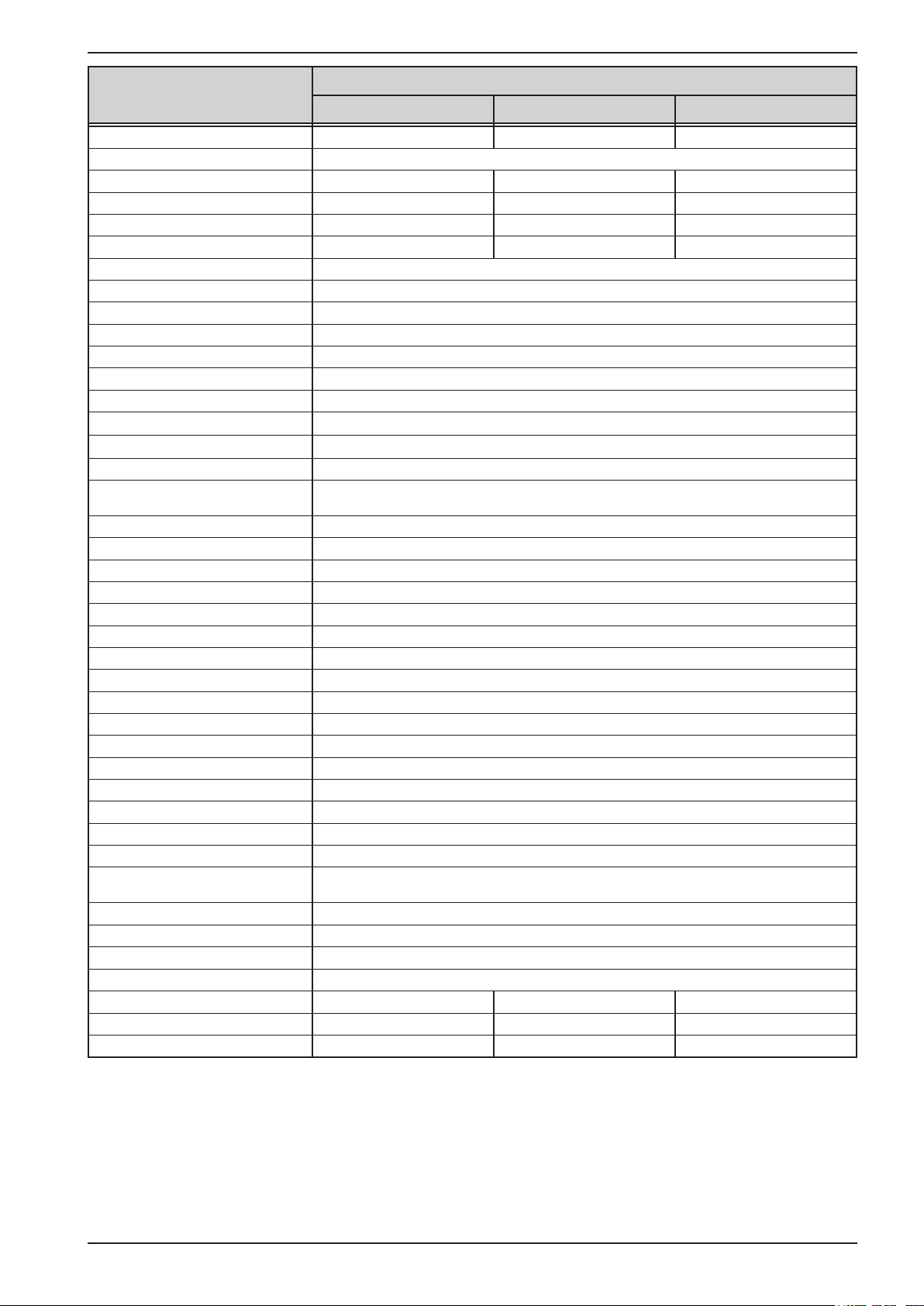
PSI 9000 2U Series
Model 2U
1500 W
Power regulation
Display: Resolution See section „1.9.6.4. Resolution of the displayed values“
Display: Accuracy
Efciency
(5
Internal resistance regulation
Adjustment range 0...720 Ω 0...1500 Ω 0...3750 Ω
Accuracy
(1
Display: Resolution See section „1.9.6.4. Resolution of the displayed values“
Analog interface
Set value inputs U, I, P, R
Actual value output U, I
Control signals DC on/off, remote control on/off, resistance mode on/off
Status signals CV, OVP, OT
Galvanic isolation to the device Max. 1500 V DC
Sample rate of inputs & outputs 500 Hz
Insulation
Output (DC) to enclosure (PE)
Input (AC) to output (DC) Max. 2500 V, short-term
Miscellaneous
Cooling Temperature controlled fans, front inlet, rear exhaust
Ambient temperature 0..50°C
Storage temperature -20...70°C
Humidity < 80%, not condensing
Standards EN 61010, EN 61326
Overvoltage category 2
Protection class 1
Pollution degree 2
Operational altitude < 2000 m
Digital interfaces
Featured 1x USB-B for communication, 1x USB-A for functions, 1x GPIB (only with option 3W)
Slot (standard version) optional: CAN, CANopen, Probus, Pronet, RS232, Ethernet, ModBus TCP
Galvanic isolation from device Max. 1500 V DC
Terminals
Rear side
Front side USB-A
Dimensions
Enclosure (WxHxD) 19“ x 2U x 463 mm
Total (WxHxD) 483 x 88 x min. 535 mm (depending on DC out terminal type)
Weight ~ 12 kg ~ 12 kg ~ 12 kg
Article number of std. model (406230311 06230312 06230313
Article number of HS model
(2
(4
PSI 9360-15 PSI 9500-10 PSI 9750-06
≤ 0.7% P
Nom
~ 93% ~ 93% ~ 93%
≤ 2% of max. resistance ± 0.3% of maximum current
DC minus: permanent max. ±400 V
DC plus: permanent max. ±400V + output voltage
Share Bus, DC output, AC input, remote sensing, analog interface, USB-B, masterslave bus, Interface module slot
(4
06730311 06730312 06730313
≤ 0.8% P
Nom
≤ 0.85% P
Nom
(1 Related to the nominal values, the accuracy denes the maximum deviation between an adjusted values and the true (actual) value.
(2 The display error adds to the error of the related actual value on the DC output
(3 For technical specications of the analog interface see „3.5.4.4 Analog interface specication“ on page 58
(4 Article number of the base version, devices with options will have a different number
(5 Typical value at 100% output voltage and 100% power
EPS Stromversorgung GmbH
Alter Postweg 101 • 86159 Augsburg
Germany
Fon: +49 821 / 570451-0
Fax: +49 821 / 570451-25
www.eps-germany.de
Page 17
Page 18

PSI 9000 2U Series
Model 2U
3000 W
AC Input
Input voltage 180...264 V AC 180...264 V AC 180...264 V AC
- with additional derating 180...207 V AC 180...207 V AC 180...207 V AC
Input connection 1ph,N,PE 1ph,N,PE 1ph,N,PE
Input frequency 45-65 Hz 45-65 Hz 45-65 Hz
Input fuse (internal) T16 A T16 A T16 A
Leak current < 3.5 mA < 3.5 mA < 3.5 mA
Power factor > 0.99 > 0.99 > 0.99
DC Output
Max. output voltage U
Max. output current I
Max. output power P
Max. output power P
Overvoltage protection range 0...44 V 0...88 V 0...220 V
Overcurrent protection range 0...132 A 0...132 A 0...55 A
Overpower protection range 0…3300 W 0…3300 W 0…3300 W
Output capacitance (std. model) 10880 μF 10880 μF 1600 μF
Output capacitance (HS model) 172 μF 172 μF 80 μF
Temperature coefcient for set
values Δ/K
Voltage regulation
Adjustment range 0...40 V 0...80 V 0...200 V
Accuracy
(1
(at 23 ± 5°C) < 0.1% U
Line regulation at ±10% ΔU
Load regulation at 0...100% load < 0.05% U
Rise time 10...90% Max. 30 ms Max. 30 ms Max. 30 ms
Settling time after load step < 1.5 ms < 1.5 ms < 1.5 ms
Display: Resolution See section „1.9.6.4. Resolution of the displayed values“
Display: Accuracy
(2
Ripple
Remote sensing compensation Max. 5% U
Output voltage fall time (at no load)
after switching DC output off
Current regulation
Adjustment range 0...120 A 0...120 A 0...50 A
Accuracy
(1
(at 23 ± 5°C) < 0.2% I
Line regulation at ±10% ΔU
Load regulation at 0...100% ΔU
(2
Ripple
Display: Resolution See section „1.9.6.4. Resolution of the displayed values“
Display: Accuracy
Power regulation
Adjustment range 0…3000 W 0…3000 W 0…3000 W
Accuracy
(1
(at 23 ± 5°C) < 1% P
Line regulation at ±10% ΔU
Load reg. at 10-90% ΔU
Max
Max
Max
with derating 2500 W 2500 W 2500 W
Max
AC
(3
AC
(3
AC
* ΔI
OUT
PSI 9040-120 PSI 9080-120 PSI 9200-50
40 V 80 V 200 V
120 A 120 A 50 A
3000 W 3000 W 3000 W
Voltage / current: 100 ppm
Nom
< 0.02% U
≤ 0.2% U
Nom
Nom
Nom
< 114 mVPP
< 8 mV
RMS
Nom
- -
Nom
OUT
OUT
< 0.05% I
< 0.15% I
< 11 mA
≤ 0.2% I
< 0.05% P
< 0.75% P
Nom
Nom
RMS
Nom
Nom
Nom
Nom
< 0.1% U
Nom
< 0.02% U
< 0.05% U
≤ 0.2% U
Nom
< 114 mVPP
< 8 mV
RMS
Max. 5% U
< 0.2% I
< 0.05% I
< 0.15% I
< 11 mA
≤ 0.2% I
< 1% P
Nom
Nom
Nom
RMS
Nom
Nom
< 0.05% P
< 0.75% P
Nom
Nom
Nom
Nom
Nom
< 0.1% U
Nom
< 0.02% U
< 0.05% U
≤ 0.2% U
Nom
< 164 mVPP
< 34 mV
RMS
Max. 5% U
Down from 100% to
<60 V: less than 10 s
< 0.2% I
< 0.05% I
< 0.15% I
< 6.5 mA
≤ 0.2% I
< 1% P
Nom
Nom
Nom
RMS
Nom
Nom
< 0.05% P
< 0.75% P
Nom
Nom
Nom
Nom
Nom
(1 Related to the nominal values, the accuracy denes the maximum deviation between an adjusted values and the true (actual) value.
Example: a 80 V model has min. 0.1% voltage accuracy, that is 80 mV. When adjusting the voltage to 5 V, the actual value is allowed to differ max. 80 mV, which
means it might be between 4.92 V and 5.08 V.
(2 RMS value: LF 0...300 kHz, PP value: HF 0...20MHz
(3 The display error adds to the error of the related actual value on the DC output
EPS Stromversorgung GmbH
Alter Postweg 101 • 86159 Augsburg
Germany
Fon: +49 821 / 570451-0
Fax: +49 821 / 570451-25
www.eps-germany.de
Page 18
Page 19
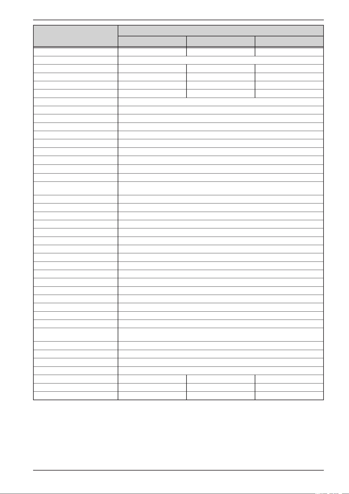
PSI 9000 2U Series
Model 2U
3000 W
Power regulation
Display: Resolution See section „1.9.6.4. Resolution of the displayed values“
Display: Accuracy
Efciency
(5
Internal resistance regulation
Adjustment range 0...10 Ω 0...20 Ω 0...120 Ω
Accuracy
(1
Display: Resolution See section „1.9.6.4. Resolution of the displayed values“
Analog interface
Set value inputs U, I, P, R
Actual value output U, I
Control signals DC on/off, remote control on/off, resistance mode on/off
Status signals CV, OVP, OT
Galvanic isolation to the device Max. 1500 V DC
Sample rate of inputs & outputs 500 Hz
Insulation
Output (DC) to enclosure (PE)
Input (AC) to output (DC) Max. 2500 V, short-term
Miscellaneous
Cooling Temperature controlled fans, front inlet, rear exhaust
Ambient temperature 0..50°C
Storage temperature -20...70°C
Humidity < 80%, not condensing
Standards EN 61010, EN 61326
Overvoltage category 2
Protection class 1
Pollution degree 2
Operational altitude < 2000 m
Digital interfaces
Featured 1x USB-B for communication, 1x USB-A for functions, 1x GPIB (only with option 3W)
Slot (standard version) optional: CAN, CANopen, Probus, Pronet, RS232, Ethernet, ModBus TCP
Galvanic isolation from device Max. 1500 V DC
Terminals
Rear side
Front side USB-A
Dimensions
Enclosure (WxHxD) 19“ x 2U x 463 mm
Total (WxHxD) 483 x 88 x min. 535 mm (depending on DC out terminal type)
Weight ~ 15 kg ~ 15 kg ~ 15 kg
Article number of std. model (406230321 06230314 06230315
Article number of HS model
(2
(3
PSI 9040-120 PSI 9080-120 PSI 9200-50
≤ 0.8% P
Nom
~ 92% ~ 92% ~ 93%
≤ 2% of max. resistance ± 0.3% of maximum current
DC minus: permanent max. ±400 V
DC plus: permanent max. ±400V + output voltage
Share Bus, DC output, AC input, remote sensing, analog interface, USB-B, masterslave bus, Interface module slot
(4
06730321 06730314 06730315
≤ 0.8% P
Nom
≤ 0.85% P
Nom
(1 Related to the nominal values, the accuracy denes the maximum deviation between an adjusted values and the true (actual) value.
(2 The display error adds to the error of the related actual value on the DC output
(3 For technical specications of the analog interface see „3.5.4.4 Analog interface specication“ on page 58
(4 Article number of the base version, devices with options will have a different number
(5 Typical value at 100% output voltage and 100% power
EPS Stromversorgung GmbH
Alter Postweg 101 • 86159 Augsburg
Germany
Fon: +49 821 / 570451-0
Fax: +49 821 / 570451-25
www.eps-germany.de
Page 19
Page 20

PSI 9000 2U Series
Model 2U
3000 W
AC Input
Input voltage 180...264 V AC 180...264 V AC 180...264 V AC
- with additional derating 180...207 V AC 180...207 V AC 180...207 V AC
Input connection 1ph,N,PE 1ph,N,PE 1ph,N,PE
Input frequency 45-65 Hz 45-65 Hz 45-65 Hz
Input fuse (internal) T16 A T16 A T16 A
Leak current < 3.5 mA < 3.5 mA < 3.5 mA
Power factor > 0.99 > 0.99 > 0.99
DC Output
Max. output voltage U
Max. output current I
Max. output power P
Max. output power P
Overvoltage protection range 0...396 V 0...550 V 0...825 V
Overcurrent protection range 0...33 A 0...22 A 0...13.2 A
Overpower protection range 0…3300 W 0…3300 W 0…3300 W
Output capacitance (std. model) 660 μF 240 μF 80 μF
Output capacitance (HS model) 40 μF 15 μF 18 μF
Temperature coefcient for set
values Δ/K
Voltage regulation
Adjustment range 0...360 V 0...500 V 0...750 V
Accuracy
(1
(at 23 ± 5°C) < 0.1% U
Line regulation at ±10% ΔU
Load regulation at 0...100% load < 0.05% U
Rise time 10...90% Max. 30 ms Max. 30 ms Max. 30 ms
Settling time after load step < 1.5 ms < 1.5 ms < 1.5 ms
Display: Resolution See section „1.9.6.4. Resolution of the displayed values“
Display: Accuracy
(2
Ripple
Remote sensing compensation Max. 5% U
Output voltage fall time (at no load)
after switching DC output off
Current regulation
Adjustment range 0...30 A 0...20 A 0...12 A
Accuracy
(1
(at 23 ± 5°C) < 0.2% I
Line regulation at ±10% ΔU
Load regulation at 0...100% ΔU
(2
Ripple
Display: Resolution See section „1.9.6.4. Resolution of the displayed values“
Display: Accuracy
Power regulation
Adjustment range 0…3000 W 0…3000 W 0…3000 W
Accuracy
(1
(at 23 ± 5°C) < 1% P
Line regulation at ±10% ΔU
Load reg. at 10-90% ΔU
Max
Max
Max
with derating 2500 W 2500 W 2500 W
Max
AC
(3
AC
(3
AC
* ΔI
OUT
PSI 9360-30 PSI 9500-20 PSI 9750-12
360 V 500 V 750 V
30 A 20 A 12 A
3000 W 3000 W 3000 W
Voltage / current: 100 ppm
Nom
< 0.02% U
≤ 0.2% U
Nom
Nom
Nom
< 210 mVPP
< 59 mV
RMS
Nom
Down from 100% to <60 V: less than 10 s
Nom
OUT
OUT
< 0.05% I
< 0.15% I
< 5 mA
≤ 0.2% I
< 0.05% P
< 0.75% P
Nom
Nom
RMS
Nom
Nom
Nom
Nom
< 0.1% U
Nom
< 0.02% U
< 0.05% U
≤ 0.2% U
Nom
< 190 mVPP
< 48 mV
RMS
Max. 5% U
< 0.2% I
< 0.05% I
< 0.15% I
< 1.5 mA
≤ 0.2% I
< 1% P
Nom
Nom
Nom
RMS
Nom
Nom
< 0.05% P
< 0.75% P
Nom
Nom
Nom
Nom
Nom
< 0.1% U
Nom
< 0.02% U
< 0.05% U
≤ 0.2% U
Nom
< 212 mVPP
< 60 mV
RMS
Max. 5% U
< 0.2% I
< 0.05% I
< 0.15% I
< 0.9 mA
≤ 0.2% I
< 1% P
Nom
Nom
Nom
RMS
Nom
Nom
< 0.05% P
< 0.75% P
Nom
Nom
Nom
Nom
Nom
(1 Related to the nominal values, the accuracy denes the maximum deviation between an adjusted values and the true (actual) value.
Example: a 80 V model has min. 0.1% voltage accuracy, that is 80 mV. When adjusting the voltage to 5 V, the actual value is allowed to differ max. 80 mV, which
means it might be between 4.92 V and 5.08 V.
(2 RMS value: LF 0...300 kHz, PP value: HF 0...20MHz
(3 The display error adds to the error of the related actual value on the DC output
EPS Stromversorgung GmbH
Alter Postweg 101 • 86159 Augsburg
Germany
Fon: +49 821 / 570451-0
Fax: +49 821 / 570451-25
www.eps-germany.de
Page 20
Page 21
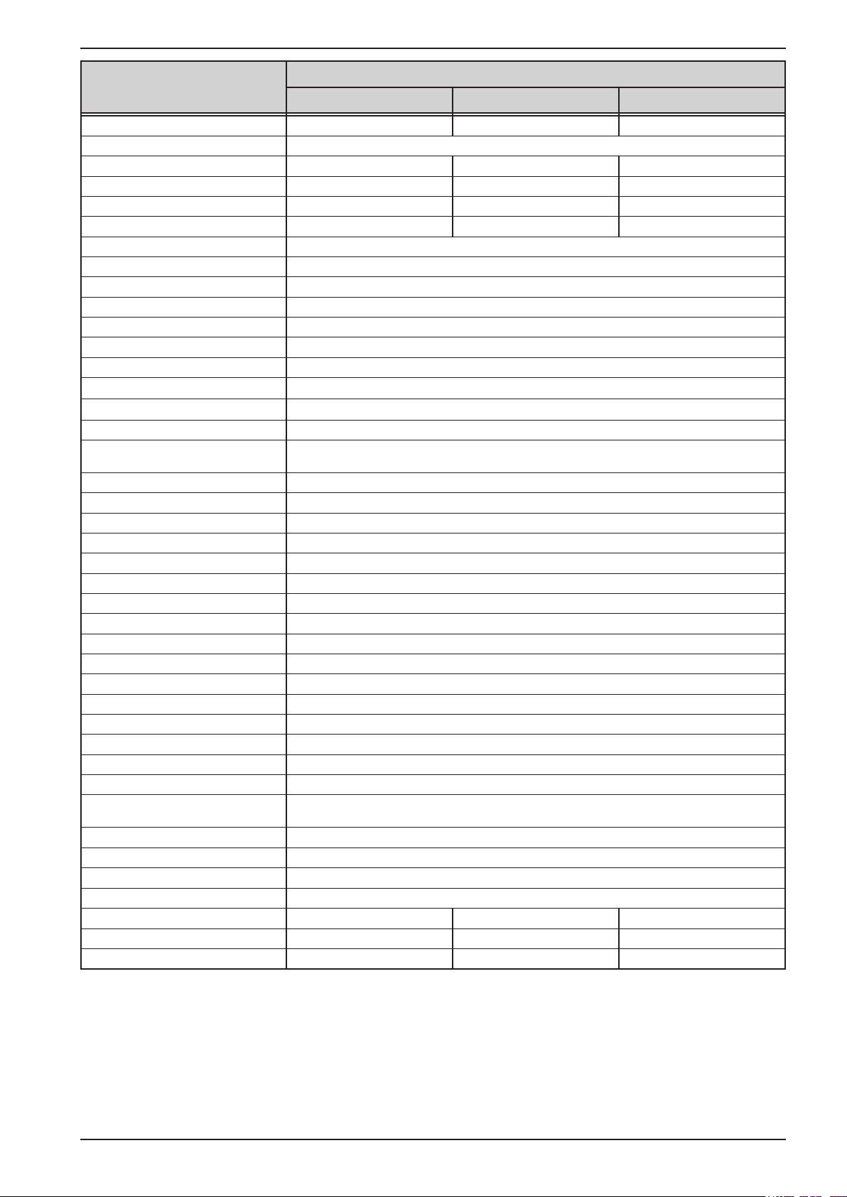
PSI 9000 2U Series
Model 2U
3000 W
Power regulation
Display: Resolution See section „1.9.6.4. Resolution of the displayed values“
Display: Accuracy
Efciency
(5
Internal resistance regulation
Adjustment range 0...360 Ω 0...750 Ω 0...1875 Ω
Accuracy
(1
Display: Resolution See section „1.9.6.4. Resolution of the displayed values“
Analog interface
Set value inputs U, I, P, R
Actual value output U, I
Control signals DC on/off, remote control on/off, resistance mode on/off
Status signals CV, OVP, OT
Galvanic isolation to the device Max. 1500 V DC
Sample rate of inputs & outputs 500 Hz
Insulation
Output (DC) to enclosure (PE)
Input (AC) to output (DC) Max. 2500 V, short-term
Miscellaneous
Cooling Temperature controlled fans, front inlet, rear exhaust
Ambient temperature 0..50°C
Storage temperature -20...70°C
Humidity < 80%, not condensing
Standards EN 61010, EN 61326
Overvoltage category 2
Protection class 1
Pollution degree 2
Operational altitude < 2000 m
Digital interfaces
Featured 1x USB-B for communication, 1x USB-A for functions, 1x GPIB (only with option 3W)
Slot (standard version) optional: CAN, CANopen, Probus, Pronet, RS232, Ethernet, ModBus TCP
Galvanic isolation from device Max. 1500 V DC
Terminals
Rear side
Front side USB-A
Dimensions
Enclosure (WxHxD) 19“ x 2U x 463 mm
Total (WxHxD) 483 x 88 x min. 535 mm (depending on DC out terminal type)
Weight ~ 15 kg ~ 15 kg ~ 15 kg
Article number of std. model (406230316 06230317 06230318
Article number of HS model
(2
(3
PSI 9360-30 PSI 9500-20 PSI 9750-12
≤ 0.85% P
Nom
~ 93% ~ 93% ~ 93%
≤ 2% of max. resistance ± 0.3% of maximum current
DC minus: permanent max. ±400 V
DC plus: permanent max. ±400V + output voltage
Share Bus, DC output, AC input, remote sensing, analog interface, USB-B, masterslave bus, Interface module slot
(4
06730316 06730317 06730318
≤ 0.85% P
Nom
≤ 0.8% P
Nom
(1 Related to the nominal values, the accuracy denes the maximum deviation between an adjusted values and the true (actual) value.
(2 The display error adds to the error of the related actual value on the DC output
(3 For technical specications of the analog interface see „3.5.4.4 Analog interface specication“ on page 58
(4 Article number of the base version, devices with options will have a different number
(5 Typical value at 100% output voltage and 100% power
EPS Stromversorgung GmbH
Alter Postweg 101 • 86159 Augsburg
Germany
Fon: +49 821 / 570451-0
Fax: +49 821 / 570451-25
www.eps-germany.de
Page 21
Page 22
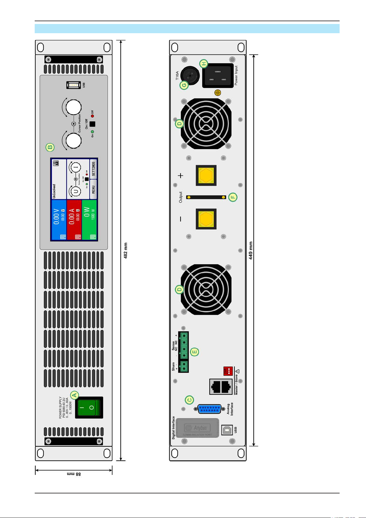
1.8.4 Views
PSI 9000 2U Series
EPS Stromversorgung GmbH
Alter Postweg 101 • 86159 Augsburg
Germany
Figure 1 - Front side
Fon: +49 821 / 570451-0
Fax: +49 821 / 570451-25
Figure 2 - Rear side (standard version)
www.eps-germany.de
A - Power switch D - Exhausts G - AC input fuse
B - Control panel E - Share Bus and remote sensing connectors H - AC input connector
C - Control interfaces (digital, analog) F - DC output (terminal type 1)
Page 22
Page 23
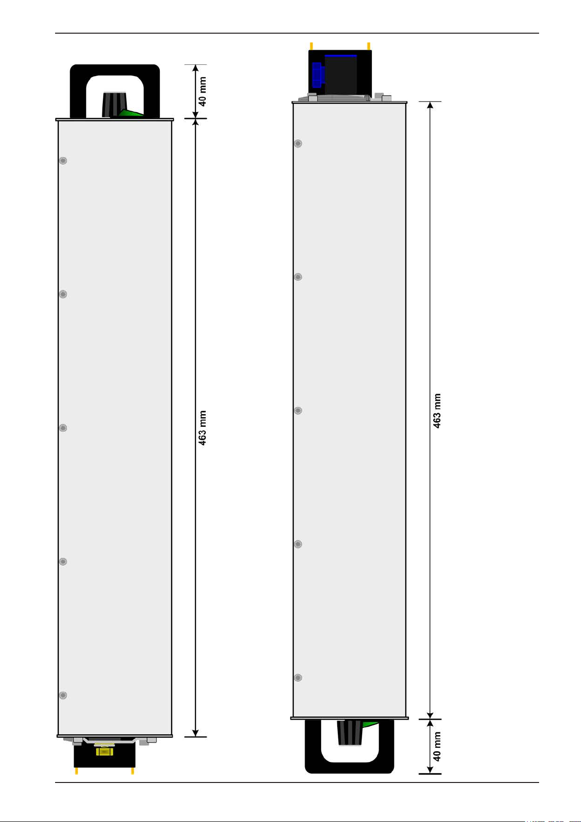
PSI 9000 2U Series
EPS Stromversorgung GmbH
Alter Postweg 101 • 86159 Augsburg
Germany
Figure 3 - Left hand side with DC terminal type 1
Fon: +49 821 / 570451-0
Fax: +49 821 / 570451-25
www.eps-germany.de
Figure 4 - Right hand side with DC terminal type 2
Page 23
Page 24
PSI 9000 2U Series
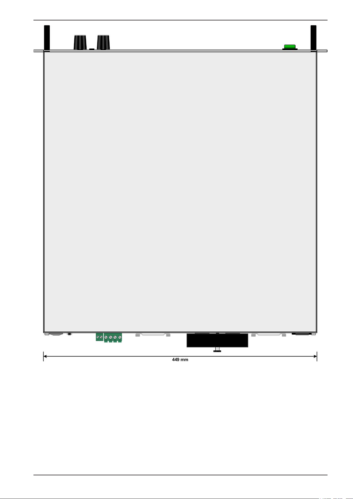
Figure 5 - View from above, with DC cover (terminal type 1)
EPS Stromversorgung GmbH
Alter Postweg 101 • 86159 Augsburg
Germany
Fon: +49 821 / 570451-0
Fax: +49 821 / 570451-25
www.eps-germany.de
Page 24
Page 25
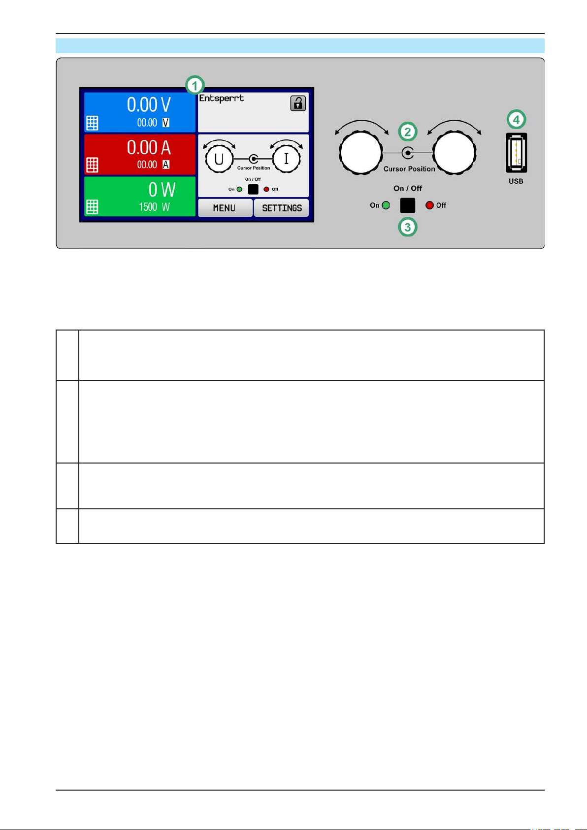
1.8.5 Control elements
Figure 6- Control Panel
Overview of the elements of the operating panel
For a detailed description see section „1.9.6. The control panel (HMI)“.
PSI 9000 2U Series
Touchscreen display
(1)
Used for selection of set values, menus, status and display of actual values and status.
The touchscreen can be operated with the ngers or with a stylus.
Rotary knob with push button function
Left knob (turn): adjusting the voltage set value, or setting the parameter values in the menu.
(2)
Left knob (push): selection of the decimal position to be changed (cursor) for the assigned value.
Right knob (turn): adjusting the current, power or resistance set value, or setting parameter values in the menu.
Right knob (push): selection of the decimal position to be changed (cursor) for the assigned value.
On/Off Button for DC output
(3)
Used to toggle the DC output between on and off, also used to start a function run. The LEDs “On” and “Off”
indicate the state of the DC output, no matter if the device is manually controlled or remotely
USB-A port
(4)
For the connection of standard USB sticks. See section „1.9.6.5. USB port (front side)“ for more details.
EPS Stromversorgung GmbH
Alter Postweg 101 • 86159 Augsburg
Germany
Fon: +49 821 / 570451-0
Fax: +49 821 / 570451-25
www.eps-germany.de
Page 25
Page 26
PSI 9000 2U Series
1.9 Construction and function
1.9.1 General description
The DC laboratory power supplies of the PSI 9000 2U series are especially suitable for test systems and industrial
applications due to their compact construction in a 19” enclosure with 2 height units. Apart from basic functions of
power supplies, set point curves can be generated in the integrated function generator (sine, rectangular, triangular
and other curve types). Arbitrary generator curves (100 points) can be saved to and loaded from an USB stick.
For remote control the devices are provided as standard with an USB port on the back side as well as a galvanically isolated analog interface.
Via optional plug-in interface modules, other digital interfaces such as Probus, ProNet, ModBus TCP, CAN,
CANopen or RS232 can be added. These enable the devices to be connected to standard industrial buses simply
by replacing or adding a small module. The conguration, if necessary at all, is simple. Thus the power supplies
may, for example, be operated with other power supplies or even other types of equipment or controlled by a PC
or PLC, all using the digital interfaces.
In addition, the devices offer as standard the possibility for parallel connection in Share bus operation for constant
current sharing plus a genuine master-slave connection with totalling of the slave units is also provided as standard.
Operating in this way allows up to 16 units to be combined to a single system with a total power of up to 48 kW.
All models are controlled by microprocessors for fast and exact measurement and display of actual values.
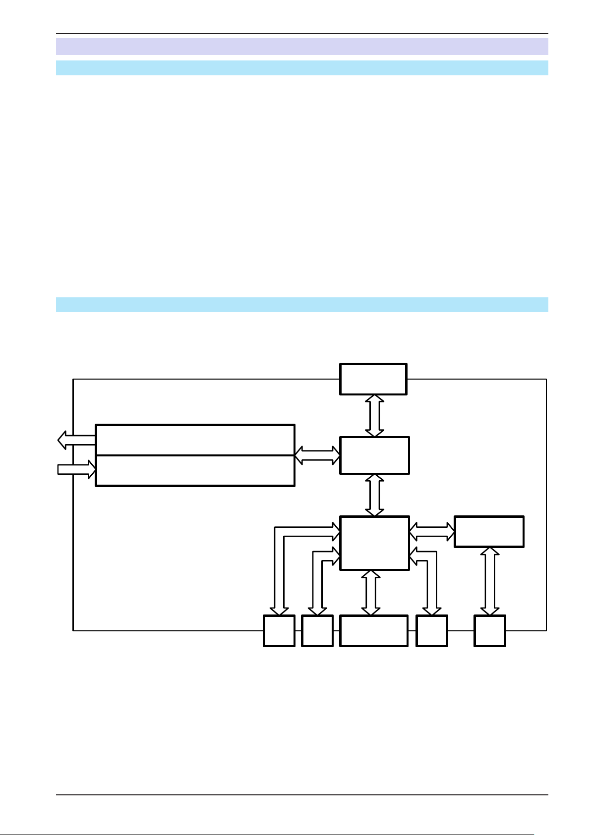
1.9.2 Block diagram
The block diagram illustrates the main components inside the device and their relationships.
There are digital, microprocessor controlled components (KE, DR, BE), which can be target of rmware updates.
Power block
DC
AC
=
≈
PSI 9000 2U/3U
Block diagram
1...3
Ana
log
Sha re &
Sense
Cont roller
(DR)
Commu-
nication
(KE)
Anybus /
GPIB (opt.)
MS
HMI (BE)
USBUSB
EPS Stromversorgung GmbH
Alter Postweg 101 • 86159 Augsburg
Germany
Fon: +49 821 / 570451-0
Fax: +49 821 / 570451-25
www.eps-germany.de
Page 26
Page 27
PSI 9000 2U Series
1.9.3 Scope of delivery
1 x Power supply device PSI 9000 2U
1 x Mains cord, 2 m, Euro plug (Schuko) and/or UK plug (depending on shipping destination)
1 x Share Bus plug (separately or plugged)
1 x Remote sensing plug (separately or plugged)
1 x USB cable, 1.8 m
1 x Set of mounting brackets (for conversion between 19” <-> desktop)
1 x USB stick with software and documentation
1.9.4 Accessories
For these devices the following accessories are available:
Digital interface modules
IF-AB
Pluggable and retrottable digital interface modules for RS232, CANopen, Ethernet, Probus, ProNet, ModBus TCP or CAN are available. Details about the
interface modules and the programming of the device using those interfaces can
be found in separate documentation. It is usually available on the USB stick, which
is included with the device, or as PDF download on the manufacturers website.
1.9.5 Options
These options are usually ordered along with the device, as they are permanently built in or precongured during
the manufacturing process. Retrotting upon request.
CABINET
19“-rack
HS
„High-Speed Ramping“
3W
GPIB interface
Racks in various congurations up to 42U as parallel systems are available, or
mixed with electronic load devices to create test systems. Further information in
our catalogue or upon request
Increased output voltage dynamics through reduced output capacity.
NOTE: other output values, as well as ripple also increase. This is a permanent
feature which cannot be switched off.
Note: HS models have a different article number. See „1.8. Technical Data“.
Replaces the standard slot for pluggable interface modules by a rigidly installed
GPIB port. This option can be retrotted upon request. The device will keep the
USB and analog interfaces. Via the GPIB port, it can only support SCPI commands.
EPS Stromversorgung GmbH
Alter Postweg 101 • 86159 Augsburg
Germany
Fon: +49 821 / 570451-0
Fax: +49 821 / 570451-25
www.eps-germany.de
Page 27
Page 28
PSI 9000 2U Series
1.9.6 The control panel (HMI)
The HMI (Human Machine Interface) consists of a display with touchscreen, two rotary knobs, a pushbutton and
an USB-A port.
1.9.6.1 Touchscreen display
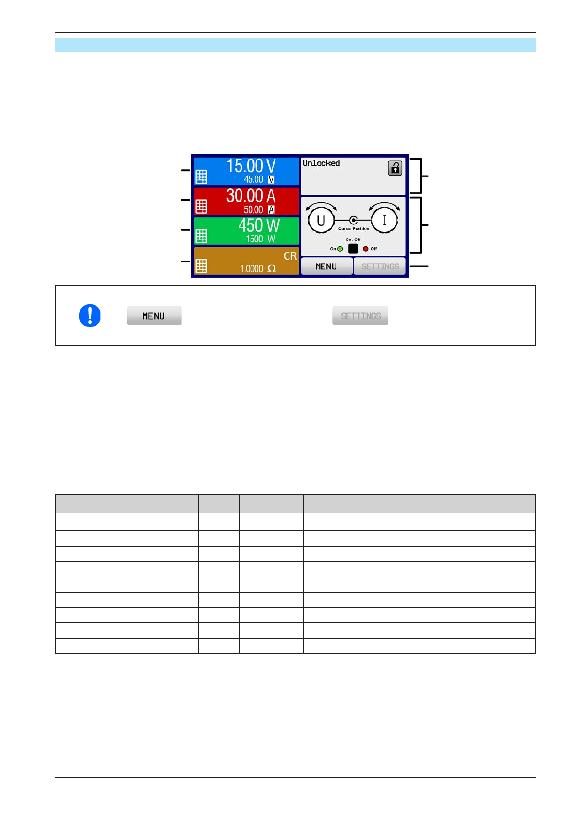
The graphic touchscreen display is divided into a number of areas. The complete display is touch sensitive and
can be operated by nger or stylus to control the equipment.
In normal operation the left hand side is used to show actual values and set values and the right hand side to
display status information:
Actual voltage display
Voltage set value input
Actual current display
Current set value input
Actual power display
Power set value input
Status area
Touch area for
rotary knob assignment
Resistance set value input
Touch areas MENU
and SETTINGS
Touch areas may be enabled or disabled:
Black text or symbol = Enabled
Grey text or symbol = Disabled
This applies to all touch areas on the main screen and all menu pages..
• Actual / set values area (left hand side)
In normal operation the DC output values (large numbers) and set values (small numbers) for voltage, current and
power are displayed. The resistance set value of the variable internal resistance is only displayed during active
resistance mode.
While the DC output is switched on, the actual regulation mode, CV, CC, CP or CR is displayed next to the cor-
responding actual value, as shown in the gure above.
The set values can be adjusted with the rotary knobs next to the display screen or can be entered directly via the
touchscreen. When adjusting with the knobs, pushing the knob will select the digit to be changed. Logically, the
values are increased by clockwise turning and decreased by anti-clockwise turning.
General display and settings ranges:
Display Unit Range Description
Actual voltage V 0-125% U
Set value of voltage
(1
V 0-102% U
Actual current A 0.2-125% I
Set value of current
(1
A 0-102% I
Actual power W 0-125% P
Set value of power
(1
W 0-102% P
Set value of internal resistance(1Ω 0-100% R
Actual values of DC output voltage
Nom
Set value for limiting the DC output voltage
Nom
Actual value of DC output current
Nom
Set value for limiting the DC output current
Nom
Actual value of output power, P = U * I
Nom
Set value for limiting DC output power
Nom
Set value for the simulated internal resistance
Max
Adjustment limits A, V, W 0-102% nom U-max, I-min etc., related to the physical values
Protection settings A, V, W 0-110% nom OVP, OCP etc., related to the physical values
(1
Valid also for values related to these physical values, such as OVD for voltage and UCD for current
EPS Stromversorgung GmbH
Alter Postweg 101 • 86159 Augsburg
Germany
Fon: +49 821 / 570451-0
Fax: +49 821 / 570451-25
www.eps-germany.de
Page 28
Page 29
PSI 9000 2U Series
• Status display (upper right)
This area displays various status texts and symbols:
Display Description
Locked The HMI is locked
Unlocked The HMI is unlocked
Remote: The device is under remote control from....
Analog ....the built-in analog interface
USB & others ....the built-in USB port or a plug in interface module
Local The device has been locked by the user explicitly against remote control
Alarm: Alarm condition which has not been acknowledged or still exists.
Event:
A user dened event has occurred which is not yet acknowledged.
Master Master-slave mode activated, device is master
Slave
Master-slave mode activated, device is slave
Function: Function generator activated, function loaded
Stopped / Running
Status of the function generator resp. of the function
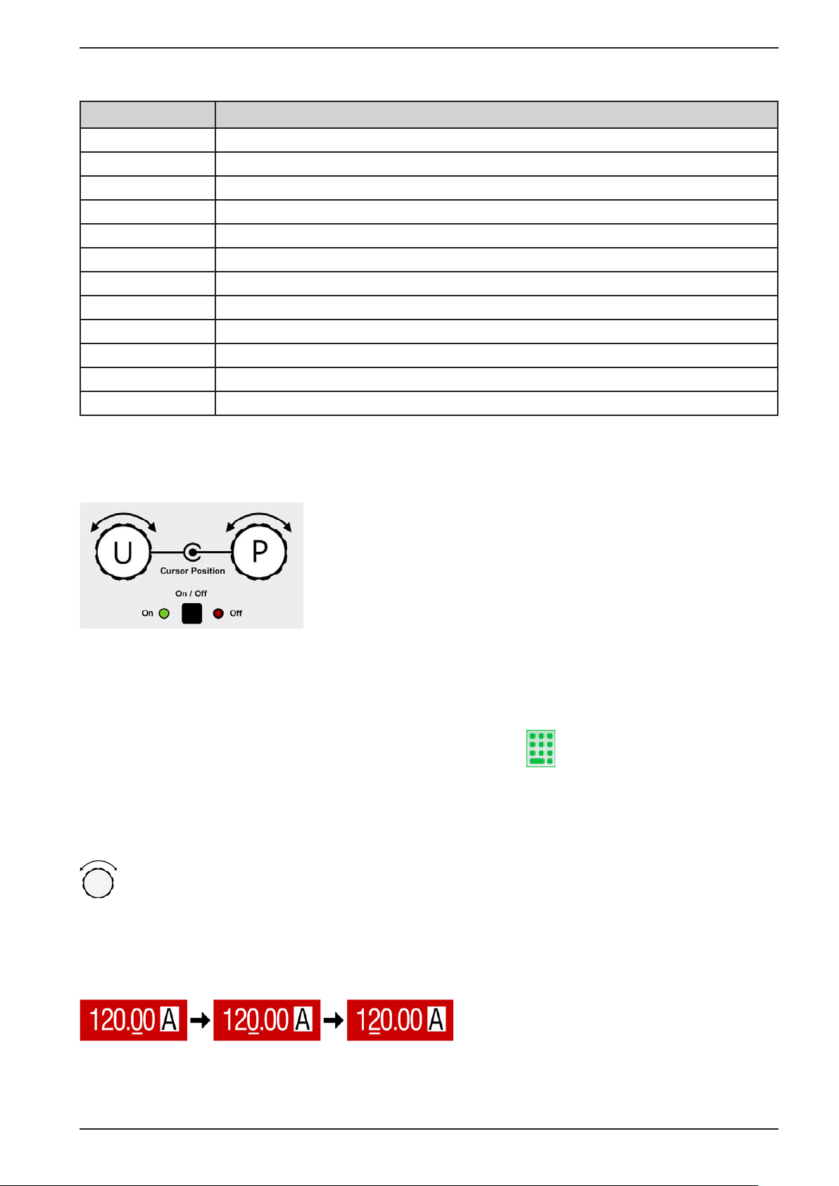
• Area for assigning the rotary knobs
The two rotary knobs next to the display screen can be assigned to various functions. This area shows the actual
assignments. These can be changed by tapping this area, as long as it’s not locked. The display changes to:
The physical values below the depiction of the knobs shows the current
assignment. On a power supply, the left knob is always assigned to the
voltage U, while the right knob can be switched by tapping the depiction.
The area will then show the assignment:
U I U P U R
Left rotary knob: voltage
Right rotary knob: current
Left rotary knob: voltage
Right rotary knob: power
Left rotary knob: voltage
Right rotary knob: resistance
The other set values can’t be adjusted via the rotary knobs, unless the assignment is changed. However, values
can be entered directly with a ten-key pad by tapping on the small icon . Alternatively to the knob depiction,
the assignment can also be changed by tapping the coloured set value areas. This method of entering values
allows for big set value steps.
1.9.6.2 Rotary knobs
As long as the device is in manual operation, the two rotary knobs are used to adjust set values, as well
as setting the parameters in SETTINGS and MENU. For a detailed description of the individual functions
see section „3.4 Manual operation“ on page 43.
1.9.6.3 Pushbutton function of the knobs
The rotary knobs also have a pushbutton function which is used in all menu options for value adjustment to move
the cursor by rotation as shown:
EPS Stromversorgung GmbH
Alter Postweg 101 • 86159 Augsburg
Germany
Fon: +49 821 / 570451-0
Fax: +49 821 / 570451-25
www.eps-germany.de
Page 29
Page 30
PSI 9000 2U Series
1.9.6.4 Resolution of the displayed values
In the display, set values can be adjusted in xed increments. The number of decimal places depends on the device
model. The values have 3 to 5 digits. Actual and set values always have the same number of digits.
Adjustable resolution and display formats for the touch panel display:
Voltage,
OVP, UVD, OVD,
U-min, U-max
Nominal
value
Step
width
Digits
Nominal
value
Current,
OCP, UCD, OCD,
I-min, I-max
Step
width
Digits
Nominal
value
Power,
OPP, OPD,
P-max
Digits
Step
width
Nominal
value
Resistance,
R-max
Digits
Step
width
≤80 V 4 0.01 V 4 A / 6 A 4 0.001 A <10000 W 4 1 W <10 Ω 5 0.0001 Ω
200 V 5 0.01 V 10 A - 25 A 5 0.001 A
≥360 V 4 0.1 V 30 A - 60 A 4 0.01 A 120 Ω - 750 Ω 5 0.01 Ω
120 A 5 0.01 A
≥300 A 4 0.1 A
Master-Slave
<10 kW
Master-Slave
≥10 kW
3 0.01 kW 10 Ω - 60 Ω 5 0.001 Ω
4 0.01 kW 1080 Ω - 5625 Ω 5 0.1 Ω
≥1200 A 4 1 A
1.9.6.5 USB port (front side)
The frontal USB port, located to the right of the rotary knobs, is intended for the connection of standard USB sticks
and can be used for loading or saving sequences for the arbitrary and the XY generator.
USB 2.0 sticks are accepted and must be FAT32 formatted and have a maximum capacity of 32GB. USB 3.0
sticks also work, but not from all manufacturers. All supported les must be held in a designated folder in the root
path of the USB drive in order to be found. This folder must be named HMI_FILES, such that a PC would recognise
the path G:\HMI_FILES if the drive were to be assigned the letter G.
The control panel of the device can read the following le types from a stick:
wave_u<arbitrary_text>.csv
wave_i<arbitrary_text>.csv
iu<arbitrary_text>.csv
ui<arbitrary_text>.csv
pv<arbitrary_text>.csv
fc<arbitrary_text>.csv
Function generator for an arbitrary function on voltage (U) or current (I)
The name must begin with wave_u / wave_i, the rest is user dened.
IU or UI table for the XY function generator.
The name must begin with iu or ui, the rest can be user dened.
PV or FC table for the XY function generator.
The name must begin with pv or fc, the rest can be user dened.
prole_<arbitrary_text>.csv Saved user prole. The number in the le name is a counter and not related to the
actual user prole number in the HMI. A max. of 10 les to select from is shown
when loading a user prole.
The control panel of the device can save the following le types to an USB stick:
usb_log_<nr>.csv File with log data recorded during normal operation in all modes. The le layout is
identical to the those generated from the Logging feature in EPS Power Control.
The <nr> eld in the le name is automatically counted up if equally named les
already exist in the folder.
prole_<nr>.csv Saved user prole. The number in the le name is a counter and not related to the
actual user prole number in the HMI. A max. of 10 les to select from is shown
when loading a user prole.
pv<nr>.csv PF function table data, as calculated by the device. Can be loaded again.
fc<nr>.csv FC function table data, as calculated by the device. Can be loaded again.
wave_u<nr>.csv
wave_i<nr>.csv
EPS Stromversorgung GmbH
Alter Postweg 101 • 86159 Augsburg
Germany
Set point data (here: sequences) from arbitrary function generator of either voltage U or current I
Fon: +49 821 / 570451-0
Fax: +49 821 / 570451-25
www.eps-germany.de
Page 30
Page 31
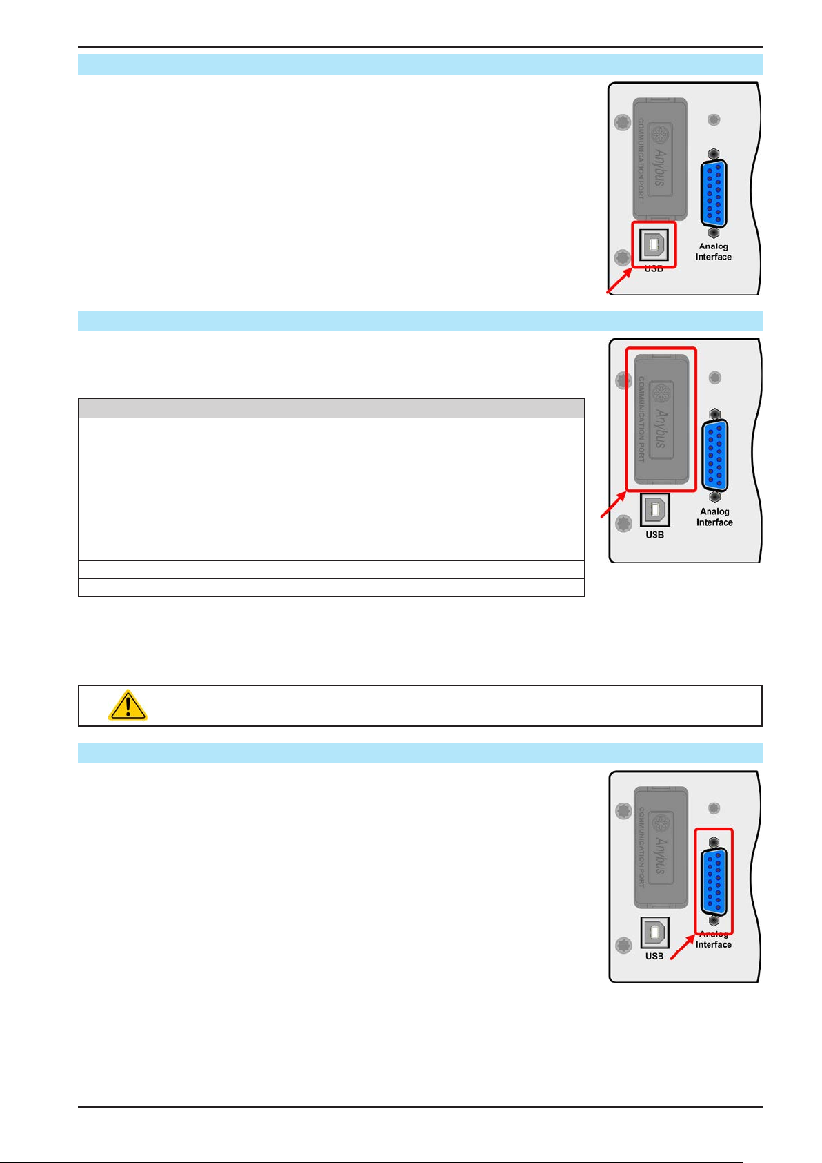
PSI 9000 2U Series
1.9.7 USB port (rear side)
The USB port on the back side of the device is provided for communication with the
device and for rmware updates. The included USB cable can be used to connect the
device to a PC (USB 2.0 or 3.0). The driver is delivered with the device and installs a
virtual COM port. Details about remote control can be found in form of a programming
guide on the included USB stick or on the web site of the manufacturer.
The device can be addressed via this port either using the international standard
ModBus RTU protocol or by SCPI language. The device recognises the message
protocol used automatically.
If remote control is in operation the USB port has no priority over either the interface
module (see below) or the analog interface and can, therefore, only be used alternatively to these. However, monitoring is always available.
1.9.8 Interface module slot
This slot on the back side of the device (only with standard models, units with option
3W installed are different) is available for various modules of the IF-AB interface
series. The following options are available:
Article number Name Description
35400100 IF-AB-CANO CANopen, 1x Sub-D 9pole male
35400101 IF-AB-RS232 RS 232, 1x Sub-D 9pole male (null modem)
35400103 IF-AB-PBUS Probus DP-V1 Slave, 1x Sub-D 9pole female
35400104 IF-AB-ETH1P Ethernet, 1x RJ45
35400105 IF-AB-PNET1P ProNET IO, 1x RJ45
35400107 IF-AB-MBUS1P ModBus TCP, 1x RJ45
35400108 IF-AB-ETH2P Ethernet, 2x RJ45
35400109 IF-AB-MBUS2P ModBus TCP, 2x RJ45
35400110 IF-AB-PNET2P ProNET IO, 2x RJ45
35400111 IF-AB-CAN CAN, 1x Sub-D 9pole male
The modules are installed by the user and can be retrotted without problem. A rmware update of the device may
be necessary in order to recognize and support certain modules.
If remote control is in operation the interface module has no priority over either the USB port or the analog interface
and can, therefore, only be used alternately to these. However, monitoring is always available.
Switch off device before adding or removing modules!
1.9.9 Analog interface
This 15 pole Sub-D socket on the back side of the device is provided for remote
control of the device via analog and digital signals.
If remote control is in operation this analog interface can only be used alternately to
the digital interface. However, monitoring is always available.
The input voltage range of the set values and the output voltage range of the monitor
values, as well as reference voltage level can be switched in the settings menu of
the device between 0-5 V and 0-10 V, in each case for 0-100%.
EPS Stromversorgung GmbH
Alter Postweg 101 • 86159 Augsburg
Germany
Fon: +49 821 / 570451-0
Fax: +49 821 / 570451-25
www.eps-germany.de
Page 31
Page 32
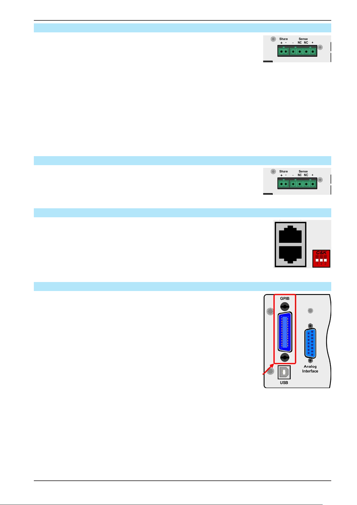
PSI 9000 2U Series
1.9.10 Share Bus-Connection
The 2 pole WAGO socket “Share” on the back side of the device is provided for
connection to equally named sockets on compatible power supply series to achieve
a balanced load current distribution during parallel connection. The socket is also
used to connect the power supply to compatible electronic loads, in order to build a
two-quadrants operation setup. Following power supply and electronic load series
are compatible:
• PS 9000 1U - 3U *
• PSI 9000 2U - 24U
• PSI 9000 3U
• PSE 9000 3U
• ELR 9000
• EL 9000 B / EL 9000 B HP / EL 9000 B 2Q
* From hardware revision 2, see type label (in case it does not show “Revision” on type label, it is revision 1)
1.9.11 Sense connector (remote sensing)
In order to compensate for voltage drops along the DC cables to the load, the Sense
input can be connected to the load.
The maximum possible compensation is given in the technical specications.
1.9.12 Master-Slave bus
A further port is provided on the back side of the device, comprising two RJ45 sockets,
which enables multiple identical devices to be connected via a digital bus (RS485)
to create a master-slave system. Connection is made using standard CAT5 cables.
These can theoretically have a length of up to 1200 m, but it is recommended to keep
the connections as short as possible.
1.9.13 GPIB port (optional)
The optional GPIB connector, which is available with option 3W, will replace the interface slot of standard version devices. The device then offers a three-way interface
with GPIB, USB and analog.
The connection to a PC or other GPIB port is done with standard GPIB cables from
stock, which can have straight or 90° connectors.
When using cable with 90° connectors, the USB port will be inaccessible.
EPS Stromversorgung GmbH
Alter Postweg 101 • 86159 Augsburg
Germany
Fon: +49 821 / 570451-0
Fax: +49 821 / 570451-25
www.eps-germany.de
Page 32
Page 33
PSI 9000 2U Series
2. Installation & commissioning
2.1 Transport and storage
2.1.1 Transport
• The handles on the front side of the device are not for carrying!
• Because of its weight, transport by hand should be avoided where possible. If unavoidable then
only the housing should be held and not on the exterior parts (handles, DC output terminal,
rotary knobs).
• Do not transport when switched on or connected!
• When relocating the equipment use of the original packing is recommended
• The device should always be carried and mounted horizontally
• Use suitable safety clothing, especially safety shoes, when carrying the equipment, as due to
its weight a fall can have serious consequences.
2.1.2 Packaging
It is recommended to keep the complete transport packaging for the lifetime of the device for relocation or return
to the manufacturer for repair. Otherwise the packaging should be disposed of in an environmentally friendly way.
2.1.3 Storage
In case of long term storage of the equipment it is recommended to use the original packaging or similar. Storage
must be in dry rooms, if possible in sealed packaging, to avoid corrosion, especially internal, through humidity.
2.2 Unpacking and visual check
After every transport, with or without packaging, or before commissioning, the equipment should be visually
inspected for damage and completeness using the delivery note and/or parts list (see section „1.9.3. Scope of
delivery“). An obviously damaged device (e.g. loose parts inside, damage outside) must under no circumstances
be put in operation.
2.3 Installation
2.3.1 Safety procedures before installation and use
• The device may, according to model, have a considerable weight. Therefore the proposed
location of the equipment (table, cabinet, shelf, 19” rack) must be able to support the weight
without restriction.
• When using a 19” rack, rails suitable for the width of the housing and the weight of the device
are to be used. (see „1.8.3. Specic technical data“)
• Before connecting to the mains ensure that the supply voltage is as shown on the product
label. Overvoltage on the AC supply can cause equipment damage.
EPS Stromversorgung GmbH
Alter Postweg 101 • 86159 Augsburg
Germany
Fon: +49 821 / 570451-0
Fax: +49 821 / 570451-25
www.eps-germany.de
Page 33
Page 34
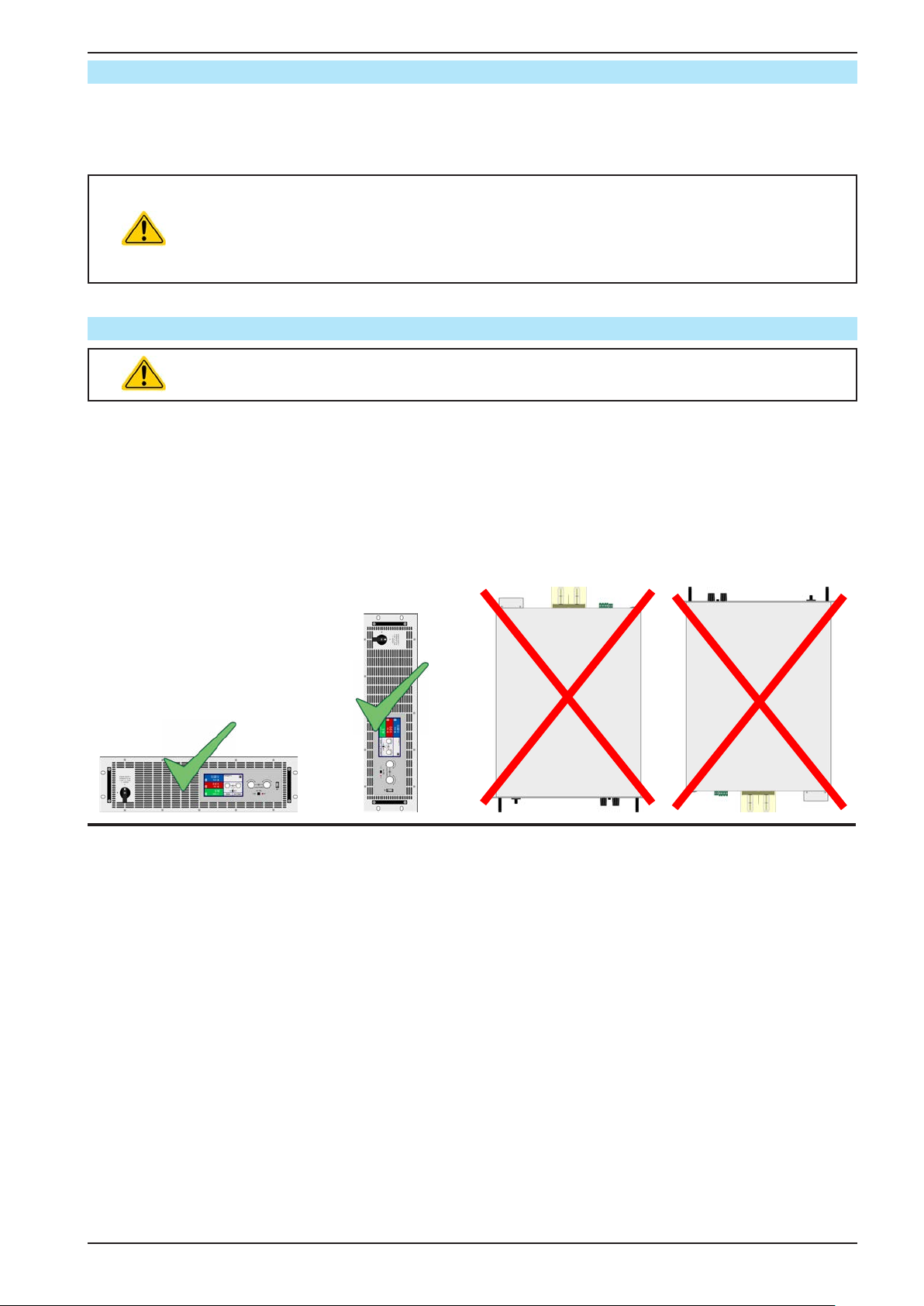
PSI 9000 2U Series
2.3.2 Preparation
Mains connection for a PSI 9000 2U series device is done via the included 2 meters long 3 pole mains cord. In
case a different AC wiring is required, make sure that the other cable has at least a cross section of 2.5 mm² (AWG
12) is used.
Dimensioning of the DC wiring to the load/consumer has to reect the following:
• The cable cross section should always be specied for at least the maximum current of the
device.
• Continuous operation at the approved limit generates heat which must be removed, as well as
voltage loss which depends on cable length and heating. To compensate for these the cable
cross section should be increased and the cable length reduced.
2.3.3 Installing the device
• Select the location for the device so that the connection to the load is as short as possible.
• Leave sufcient space behind the equipment, minimum 30cm, for ventilation.
A device in a 19” housing will usually be mounted on suitable rails and installed in 19” racks or cabinets. The depth
of the device and its weight must be taken into account. The handles on the front are for sliding in and out of the
cabinet. Slots on the front plate are provided for xing the device (xing screws not included).
With all models of this series, mounting brackets are included to convert the front plate from a 19” to desktop.
In order to do that, the 19” mounting brackets can be removed after loosening the screws on the front grips and
replacing them by included pieces, or vice versa.
Acceptable and inacceptable installation positions:
EPS Stromversorgung GmbH
Alter Postweg 101 • 86159 Augsburg
Germany
Standing surface
Fon: +49 821 / 570451-0
Fax: +49 821 / 570451-25
www.eps-germany.de
Page 34
Page 35
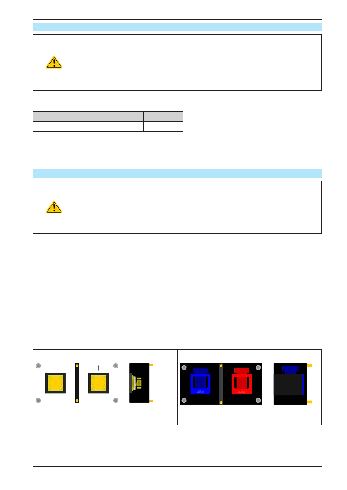
PSI 9000 2U Series
2.3.4 Connection to AC supply
• The device can be connected to any wall socket or multi-socket outlet, as long as those feature
a safety contact (PE) and are capable for 16 A.
• When connecting the device to a multi-socket outlet, along with other electric devices, it is
important to consider the total power consumption of all devices on the outlet, so that the maxi-
mum current (power ÷ minimum voltage) does not exceed the denition for the wall socket,
the multi-socket outlet and/or main distribution
• Before plugging in the input plug ensure that the device is switched off by its mains switch!
The device is delivered with a 3-pole mains cord for standard wall socket connection and supply. If it shall be connected to a 2-phase or 3-phase supply, following phases are required:
Nominal power Phases Supply type
1 kW - 3 kW L1 or L2 or L3, N, PE Wall socket
The default input values of all models in this series are: 230 V, 16 A, 50 Hz. It is fused with 16 A. The maximum
input current depends on the higher current intake at low AC voltage (for minimum input voltage see technical
specs). Custom made cables thus require to have a cross section of 1.5 mm² (AWG16) minimum per lead, recommend is 2.5 mm² (AWG12).
2.3.5 Connection to DC loads
• In the case of a device with a high nominal current and hence a thick and heavy DC connection cable it is necessary to take account of the weight of the cable and the strain imposed
on the DC connection. Especially when mounted in a 19” cabinet or similar, where the cable
hangs on the DC output, a strain reliever should be used.
• Connection to and operation with transformerless DC-AC inverters (for example solar inverters) is restricted, because the inverter can shift the potential of negative output (DC-)
against PE (ground). Mind the max. allowed potential shift (see technical specications)!
The DC load output is on the rear side of the device and is not protected by a fuse. The cross section of the connection cable is determined by the current consumption, cable length and ambient temperature.
For cables up to 1.5 m and average ambient temperature up to 50°C, we recommend:
up to 10 A: 0,75 mm² (AWG18) up to 15 A: 1,5 mm² (AWG14)
up to 30 A: 4 mm² (AWG10) up to 40 A: 6 mm² (AWG8)
up to 60 A: 16 mm² (AWG4) up to 120 A: 35 mm² (AWG1)
per lead (multi-conductor, insulated, openly suspended). Single cables of, for example, 35 mm² may be replaced
by e.g. 2x 16 mm² etc. If the cables are long then the cross section must be increased to avoid voltage loss and
overheating.
2.3.5.1 DC terminal types
The table below shows an overview of the various DC terminals. It is recommended that connection of load cables
always utilises exible cables with ring lugs.
Type 1: Models up to 80 V output voltage Type 2: Models from 200 V output voltage
M8 (8 mm) bolt on a brass block
Recommendation: M8 ring lug with a 8.4 mm hole
EPS Stromversorgung GmbH
Alter Postweg 101 • 86159 Augsburg
Germany
Fon: +49 821 / 570451-0
Fax: +49 821 / 570451-25
Screw clamp connection M6, on copper rail
Recommendation: M6 ring lug with a 6.5 mm hole
www.eps-germany.de
Page 35
Page 36
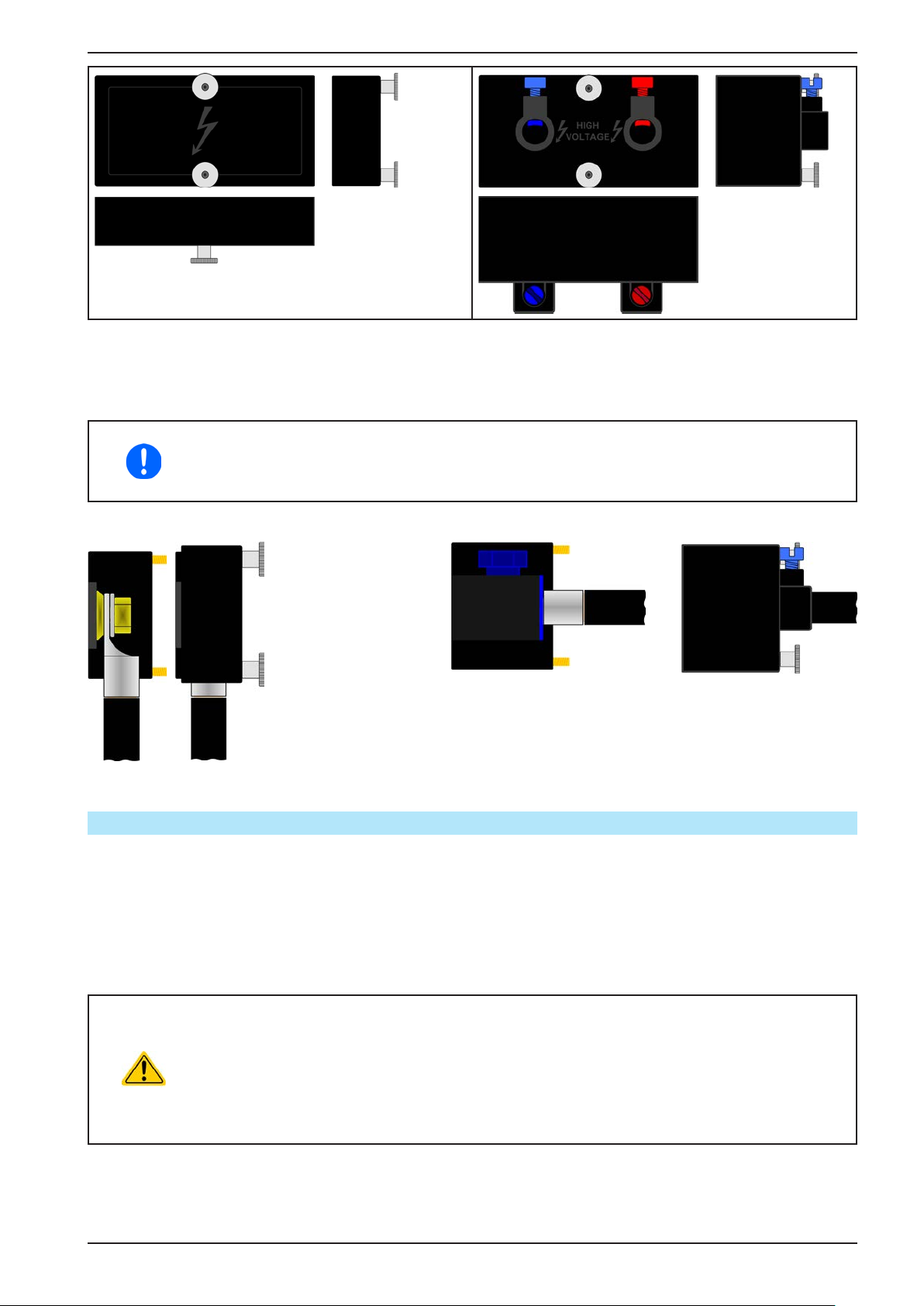
PSI 9000 2U Series
2.3.5.2 Cable lead and plastic cover
A plastic cover for contact protection is included for the DC terminal. It should always be installed. Both covers are
mounted to the DC terminal itself.
The connection angle and the required bending radius for the DC cable must be taken into
account when planning the depth of the complete device, especially when installing in a 19”
cabinet or similar. For type 2 connectors only a horizontal lead can be used to allow for installation of the cover.
Connection examples:
• Type 1, up or down
• Space saving in depth
• No bending radius
• Type 2, horizontal lead
• Space saving in height
• Large bending radius
2.3.6 Grounding of the DC output
No matter if the power supply is operated stand-alone or in series connection with others, it is always only allowed
to ground one of all DC output poles. Following also has to be considered:
Due to limitations with the isolation a max. potential shift of ±400 V DC on the DC minus pole is allowed.
The DC minus pole of a stand-alone unit can be grounded right away, but it should only be done if absolutely nec-
essary, because the DC output is connected to PE via X capacitors in order to gain a better HF ltering.
Grounding the DC plus pole is only allowed for models where the nominal output voltage does not exceed the 400
V DC limit, else the potential shift on the DC minus could exceed that limit.
• Grounding of the DC-plus pole for any model with >400 V nominal voltage only at one’s own
risk! Risk of damaging the device! Risk of voiding warranty!
• Digital and analog interface are galvanically isolated from the DC output and should never be
grounded, but under no circumstances if any of the DC output poles is grounded too, because
this will cancel the galvanic isolation
• If grounding one of the DC output poles check if any pole of the load is already grounded. This
could lead to a short circuit!
EPS Stromversorgung GmbH
Alter Postweg 101 • 86159 Augsburg
Germany
Fon: +49 821 / 570451-0
Fax: +49 821 / 570451-25
www.eps-germany.de
Page 36
Page 37
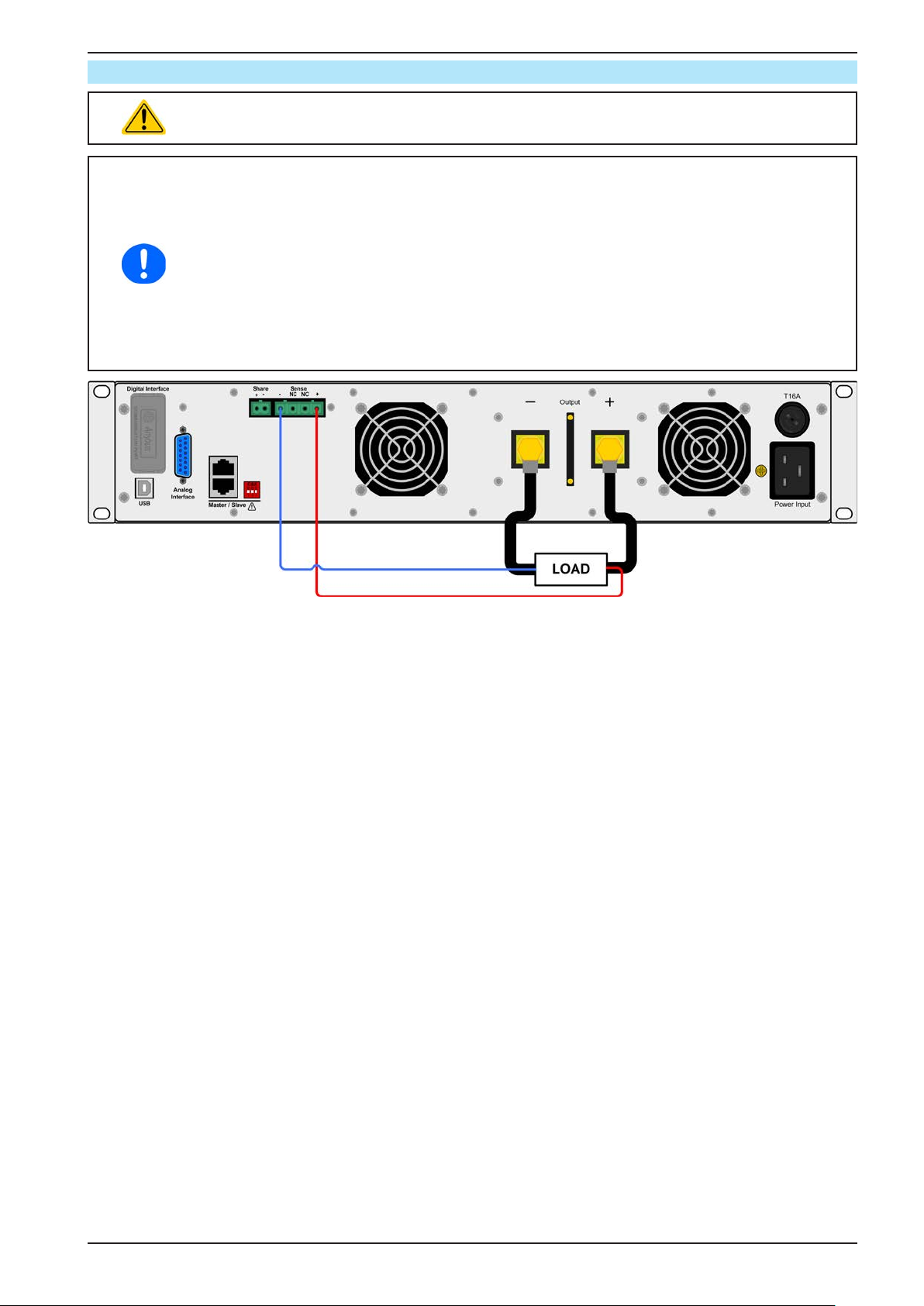
2.3.7 Connection of remote sensing
• Both pins „NC“ of the Sense connector must not be wired!
• Mind the electric strength of the sense cables, especially with models of ≥ 500 V rating!
• Remote sensing is only effective during constant voltage operation (CV) and for other regulation
modes the sense input should be disconnected, if possible, because connecting it generally
increases the oscillation tendency
• The cross section of the sense cables is noncritical. However, it should be increased with
increasing cable length. Recommendation: for cables up to 5 m use at least 0.5 mm²
• Sense cables should be twisted and laid close to the DC cables to damp oscillation. If neces-
sary, an additional capacitor should be installed at the load/consumer to eliminate oscillation
• The sense cables must be connected + to + and - to - at the load, otherwise both systems
may be damaged
• In master-slave operation, the remote sensing should be connected to the master unit only
PSI 9000 2U Series
Figure 7 - Example for remote sensing wiring
EPS Stromversorgung GmbH
Alter Postweg 101 • 86159 Augsburg
Germany
Fon: +49 821 / 570451-0
Fax: +49 821 / 570451-25
www.eps-germany.de
Page 37
Page 38
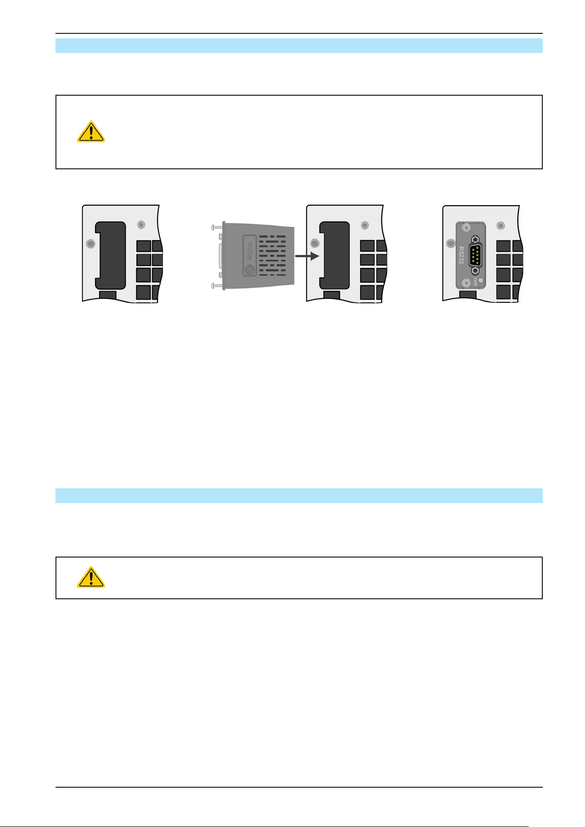
PSI 9000 2U Series
2.3.8 Installation of an interface module
The optionally obtainable interface modules can be retrotted by the user and are exchangeable with each other.
The settings for the currently installed module vary and need to be checked and, if necessary, corrected on initial
installation and after module exchange.
• Common ESD protection procedures apply when inserting or exchanging a module.
• The device must be switched off before insertion or removal of a module
• Never insert any other hardware other than an interface module into the slot
• If no module is in use it is recommended that the slot cover is mounted in order to avoid internal
dirtying of the device and changes in the air ow.
Installation steps:
1. 2. 3.
With the help of a Torx
8 screw driver either
remove the slot cover
(dummy module) an already installed module.
The screws can be used
to assist in pulling out the
module.
Make sure the screws
are fully retracted. If not,
unscrew them further
Insert the interface module into the slot. The
shape ensures correct alignment.
When inserting take care that it is held as
close as possible to a 90° angle to the rear
wall of the device. Use the green PCB, which
you can recognize on the open slot as guide.
At the end is a socket for the module.
On the underside of the module are two plastic
nibs which must click into the green PCB so
that the module is properly aligned on the rear
wall of the device.
The screws (Torx 8) are pro-
vided for xing the module
and should be fully screwed
in. After installation, the
module is ready for use and
can be connected.
Removal follows the reverse
procedure.
and remove the module.
2.3.9 Connecting the analog interface
The 15 pole connector (Type: Sub-D, D-Sub) on the rear side is an analog interface. To connect this to a controlling hardware (PC, electronic circuit), a standard plug is necessary (not included in the scope of delivery). It is
generally advisable to switch the device completely off before connecting or disconnecting this connector, but at
least the DC output.
The analog interface is galvanically isolated from the device internally. Unless absolutely required, do not connect any ground of the analog interface (AGND) to the DC minus output as
this will cancel the galvanic isolation.
EPS Stromversorgung GmbH
Alter Postweg 101 • 86159 Augsburg
Germany
Fon: +49 821 / 570451-0
Fax: +49 821 / 570451-25
www.eps-germany.de
Page 38
Page 39
PSI 9000 2U Series
2.3.10 Connecting the “Share” bus
The “Share” bus connector on the back side is intended to balance the current of multiple units in parallel operation, especially when using the integrated function generator of the master unit. Alternatively, it can be connected
to a compatible electronic load, like from series ELR 9000, in order to run a two-quadrants operation. For further
information about this mode of operation can be found in section „3.11.4. Two quadrant operation (2QO)“ .
For the connection of the share bus the following must be paid attention to:
• Connection is only permitted between compatible devices (see „1.9.10. Share Bus-Connection“
for details) and between a max. of 16 units
• If a two-quadrants operation system has to be set up where multiple power supplies are connected to one electronic load unit or a group of electronic loads, all units should be connected
via Share bus.
• When not using one or several units of a system congured with Share bus, because less power
is required for an application, it is recommended to disconnect the unit’s from the Share bus,
because even when not powered they can have a negative impact on the control signal on the
bus due to their impedance. Disconnection can be done by simply unplugging them from the
bus or using switches.
• The Share bus is referenced to DC minus. When building a series connection (where allowed,
depending on model), the DC minus will shift its potential and so will the Share bus
2.3.11 Connecting the USB port (rear side)
In order to remotely control the device via this port, connect the device with a PC using the included USB cable
and switch the device on.
2.3.11.1 Driver installation (Windows)
On the initial connection with a PC the operating system will identify the device as new hardware and will try to
install a driver. The required driver is for a Communications Device Class (CDC) device and is usually integrated in
current operating systems such as Windows 7 or 10. But it is strongly recommended to use and install the included
driver installer (on USB stick) to gain maximum compatibility of the device to our softwares.
2.3.11.2 Driver installation (Linux, MacOS)
We cannot provide drivers or installation instructions for these operating systems. Whether a suitable driver is
available is best carried out by searching the Internet.
2.3.11.3 Alternative drivers
In case the CDC drivers described above are not available on your system, or for some reason do not function
correctly, commercial suppliers can help. Search the Internet for suppliers using the keywords “cdc driver windows“
or “cdc driver linux“ or “cdc driver macos“.
2.3.12 Initial commission
For the rst start-up after installation of the device, the following procedures have to be executed:
• Conrm that the connection cables to be used are of a satisfactory cross section!
• Check if the factory settings of set values, safety and monitoring functions and communication are suitable for
your intended application of the device and adjust them if required, as described in the manual!
• In case of remote control via PC, read the additional documentation for interfaces and software!
• In case of remote control via the analog interface, read the section in this manual concerning analog interfaces!
2.3.13 Commission after a rmware update or a long period of non-use
In case of a rmware update, return of the equipment following repair or a location or conguration change, similar
measures should be taken to those of initial start up. Refer to „2.3.12. Initial commission“.
Only after successful checking of the device as listed may it be operated as usual.
EPS Stromversorgung GmbH
Alter Postweg 101 • 86159 Augsburg
Germany
Fon: +49 821 / 570451-0
Fax: +49 821 / 570451-25
www.eps-germany.de
Page 39
Page 40
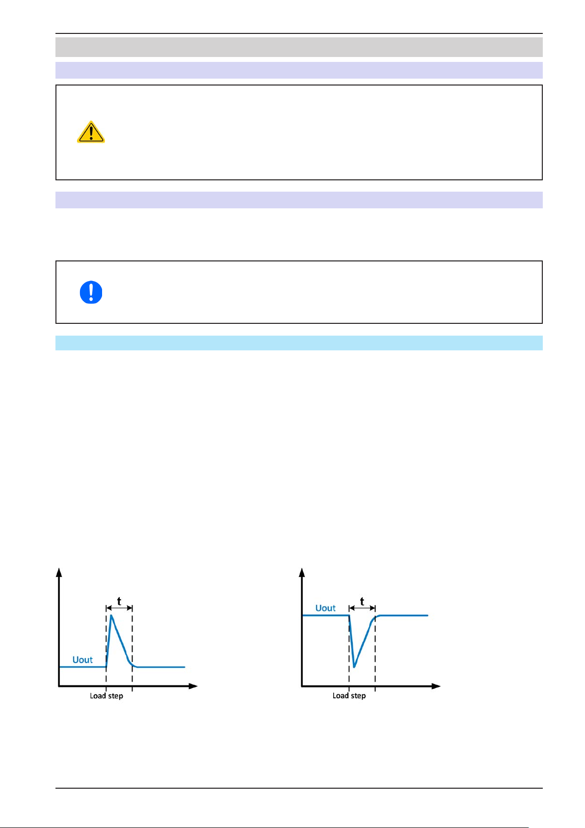
PSI 9000 2U Series
3. Operation and application
3.1 Personal safety
• In order to guarantee safety when using the device, it is essential that only persons operate
the device who are fully acquainted and trained in the required safety measures to be taken
when working with dangerous electrical voltages
• For models which can generate a voltage which is dangerous by contact, or is connected to
such, the included DC terminal cover, or an equivalent, must always be used
• Whenever the load and DC output are being re-congured, the device should be disconnected
from the mains, not only the DC output switched off!
3.2 Operating modes
A power supply is internally controlled by different control or regulation circuits, which shall bring voltage, current
and power to the adjusted values and hold them constant, if possible. These circuits follow typical laws of control
systems engineering, resulting in different operating modes. Every operating mode has its own characteristics
which is explained below in short form.
• Unloaded operation is not considered as a normal operation mode and can thus lead to false
measurements, for example when calibrating the device
• The optimal working point of the device is between 50% and 100% voltage and current
• It is recommended to not run the device below 10% voltage and current, in order to make
sure technical values like ripple and transient times can be met
3.2.1 Voltage regulation / Constant voltage
Voltage regulation is also called constant voltage operation (CV).
The DC output voltage of a power supply is held constant on the adjusted value, unless the output current or the
output power according to P = U
will automatically change to constant current or constant power operation, whatever occurs rst. Then the output
voltage can’t be held constant anymore and will sink to a value resulting from Ohm’s law.
While the DC output is switched on and constant voltage mode is active, then the condition “CV mode active” will
be indicated on the graphic display by the abbreviation CV and this message will be passed as a signal to the
analog interface, as well stored as status which can also be read as a status message via digital interface.
3.2.1.1 Transient time after load step
For constant voltage mode (CV), the technical date “Settling time after load step” (see 1.8.3) denes a time that is
required by the internal voltage regulator of the device to settle the output voltage after a load step. Negative load
steps, i.e. high load to lower load, will cause the output voltage to overshoot for a short time until compensated by
the voltage regulator. The same occurs with a positive load step, i.e. low load to high load. There the output collapses for a moment. The amplitude of the overshoot resp. collapse depends on the device model, the currently
adjusted output voltage and the capacity on the DC output and can thus not be stated with a specic value.
Depictions:
OUT
* I
reaches the adjusted current or power limit. In both cases the device
OUT
Example for neg. load step: the DC output will rise
above the adjusted value for a short time. t = transient
time to settle the output voltage.
EPS Stromversorgung GmbH
Alter Postweg 101 • 86159 Augsburg
Germany
Fon: +49 821 / 570451-0
Fax: +49 821 / 570451-25
Example for pos. load step: the DC output will collapse
below the adjusted value for a short time. t = transient
time to settle the output voltage.
www.eps-germany.de
Page 40
Page 41
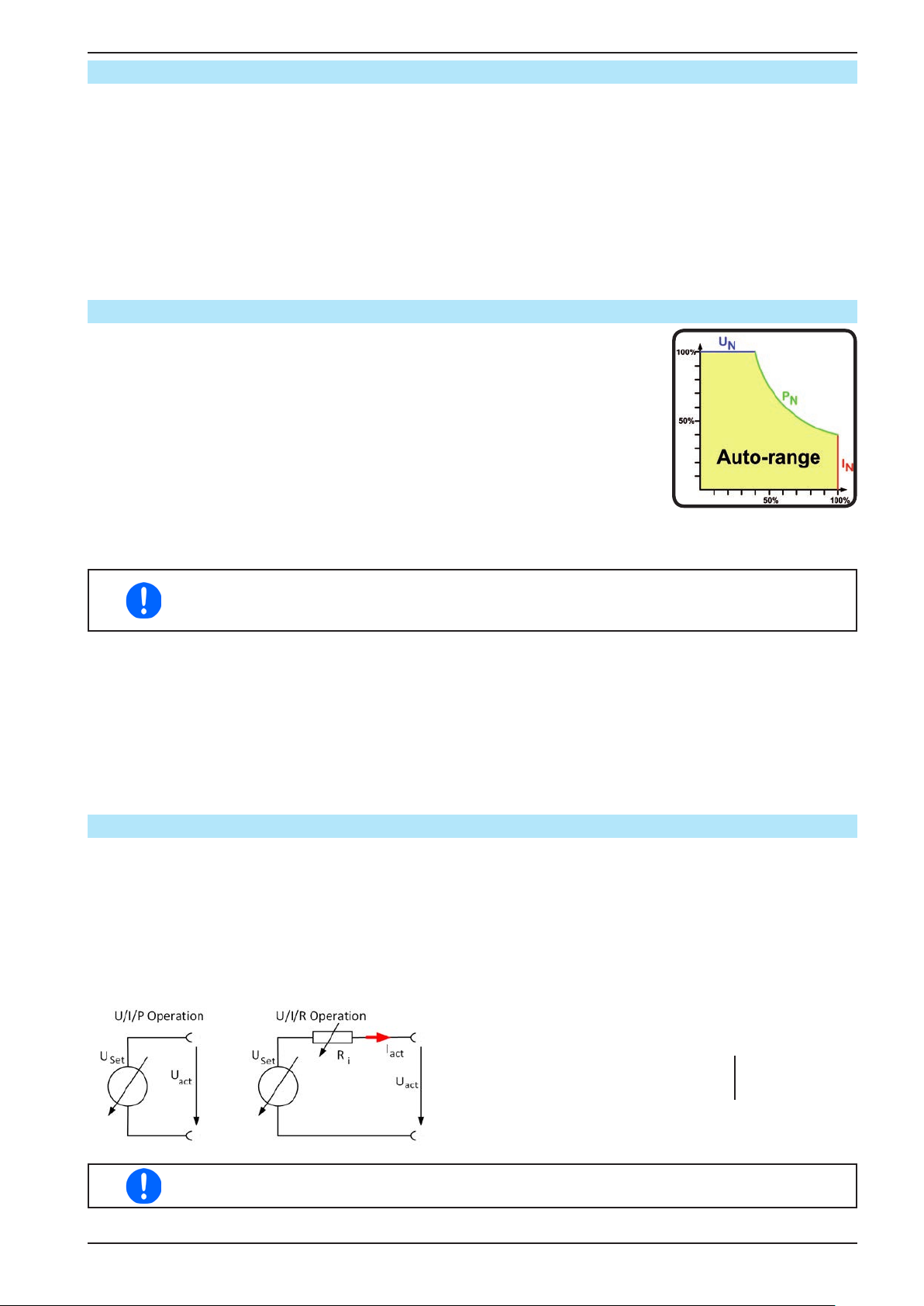
PSI 9000 2U Series
3.2.2 Current regulation / constant current / current limiting
Current regulation is also known as current limiting or constant current mode (CC).
The DC output current is held constant by the power supply, once the output current to the load reaches the adjusted
limit. The current owing from the power supply is determined by the output voltage and the load’s true resistance.
As long as the output current is lower than the adjusted current limit, the device will be either in constant voltage
or constant power mode. If, however, the power consumption reaches the set maximum power value, the device
will switch automatically to power limiting and sets the output current according to I
maximum current value is higher. The current set value, as determined by the user, is always an upper limit only.
While the DC output is switched on and constant current mode is active, then the condition “CC mode active” will
be indicated on the graphic display by the abbreviation CC and this message will be passed as a signal to the
analog interface, as well stored as status which can also be read as a status message via digital interface.
3.2.3 Power regulation / constant power / power limiting
Power regulation, also known as power limiting or constant power (CP), keeps the
DC output power of a power supply constant if the current owing to the load in
relation to the output voltage and the resistance of load reaches the adjusted value
according to P = U * I resp. P = U² / R. The power limiting then regulates the output
current according to I = sqr(P / R), where R is the load’s resistance.
Power limiting operates according to the auto-range principle such that at lower
output voltages higher current ows and vice versa in order to maintain constant
power within the range P
While the DC output is switched on and constant power mode is active, then the
condition “CP mode active” will be shown on the graphic display by the abbreviation CP, as well stored as status which can also be read as a status message via
digital interface.
(see diagram to the right).
N
MAX
= P
/ UIN , even if the
SET
When using remote sensing, the power supply can deliver a higher voltage on the DC output
than adjusted, which results in additional power and may also cause the device to enter power
limitation without explicitly indicating “CP” in the display.
3.2.3.1 Power derating
Due to fusing and cross sections of conductors and the extended input voltage range, power supply models as
from 1500 W have a xed derating. It becomes active below a certain input voltage level (for value see „1.8.3.
Specic technical data“) and will derate the maximum available output power for a 1500 W model down to 1000 W
and for a 3000 W model down to 2500 W. The derating only affects the available output power, thus the full range
for power set value adjustment remains, though the device will switch earlier to constant power operation. This
situation of constant power operation won’t be indicated by status “CP”. Active derating can then only be detected
by reading the actual values of voltage and current and by calculating the power.
3.2.4 Internal resistance regulation
Internal resistance control (abbr. CR) of power supplies is the simulation of a virtual internal resistor which is in
series to the voltage source and thus also in series to the load. According to Ohm’s law, this causes a voltage
drop, which will result in a difference between adjusted output voltage and actual output voltage. This will work in
constant current mode as well as in constant power mode, but here the output voltage will differ even more from
the adjusted voltage, because then constant voltage is not active.
The adjustable resistance range of a particular model is given in the technical specications. The voltage setting
in dependency of the resistance set value and the output current is done by calculation of the microcontroller and
thus will be signicantly slower the other controllers inside the control circuit. Clarication:
With resistance mode being activated the function generator will be unavailable and the actual
power value provided by the device does not include the simulated power dissipation of Ri.
EPS Stromversorgung GmbH
Alter Postweg 101 • 86159 Augsburg
Germany
U
Fon: +49 821 / 570451-0
Fax: +49 821 / 570451-25
= U
Act
PRi = (U
- I
Set
Set
- U
Act
) * I
Act
www.eps-germany.de
* R
Act
Set
P
, I
Set
Set
Page 41
Page 42
PSI 9000 2U Series
3.3 Alarm conditions
This section only gives an overview about device alarms. What to do in case your device indicates an alarm condition is described in section „3.6. Alarms and monitoring“.
As a basic principle, all alarm conditions are signalled optically (text + message in the display), acoustically (if
activated) and as a readable status and alarm counter via the digital interface. In addition, the alarms OT and
OVP are reported as signals on the analogue interface. For later acquisition, an alarm counter can be read from
the display or via digital interface.
3.3.1 Power Fail
Power Fail (PF) indicates an alarm condition which may have various causes:
• AC input voltage too low (mains undervoltage, mains failure)
• Defect in the input circuit (PFC)
As soon as a power fail occurs, the device will stop to supply power and switch off the DC output. In case the
power fail was an undervoltage and is gone later on, the alarm will vanish from display and doesn’t require to be
acknowledged.
Switching off the device by the mains switch can’t be distinguished from a mains blackout and thus
the device will signalise a PF alarm every time the device is switched off. This can be ignored.
The condition of the DC output after a PF alarm during normal operation can be set up. See
„3.4.3. Conguration via MENU“.
3.3.2 Overtemperature
An overtemperature alarm (OT) can occur from an excess temperature inside the device and temporarily causes
it to stop supplying power. After cooling down, the device will automatically continue to supply power, while the
condition of the DC output remains and the alarm doesn’t require to be acknowledged.
3.3.3 Overvoltage protection
An overvoltage alarm (OVP) will switch off the DC output and can occur if:
• the power supply itself, as a voltage source, generates an output voltage higher than set for the overvoltage
alarm threshold (OVP, 0...110% U
) or the connected load somehow returns voltage higher than set for the
Nom
overvoltage alarm limit
• the OV threshold has been adjusted too close above the output voltage. If the device is in CC mode and if it
then experiences a negative load step, it will make the voltage rise quickly, resulting in an voltage overshoot for
a short moment which can already trigger the OVP
This function serves to warn the user of the power supply acoustically or optically that the device probably has
generated an excessive voltage which could damage the connected load application.
• The device is not tted with protection from external overvoltage
• The changeover from operation modes CC -> CV can generate voltage overshoots
3.3.4 Overcurrent protection
An overcurrent alarm (OCP) will switch off the DC output and can occur if:
• the output current in the DC output exceeds the adjusted OCP limit.
This function serves to protect the connected load application so that this is not overloaded and possibly damaged
due to an excessive current.
3.3.5 Overpower protection
An overpower alarm (OPP) will switch off the DC output and can occur if:
• the product of the output voltage and output current in the DC output exceeds the adjusted OPP limit.
This function serves to protect the connected load application so that this is not overloaded and possibly damaged
due to an excessive power consumption.
EPS Stromversorgung GmbH
Alter Postweg 101 • 86159 Augsburg
Germany
Fon: +49 821 / 570451-0
Fax: +49 821 / 570451-25
www.eps-germany.de
Page 42
Page 43
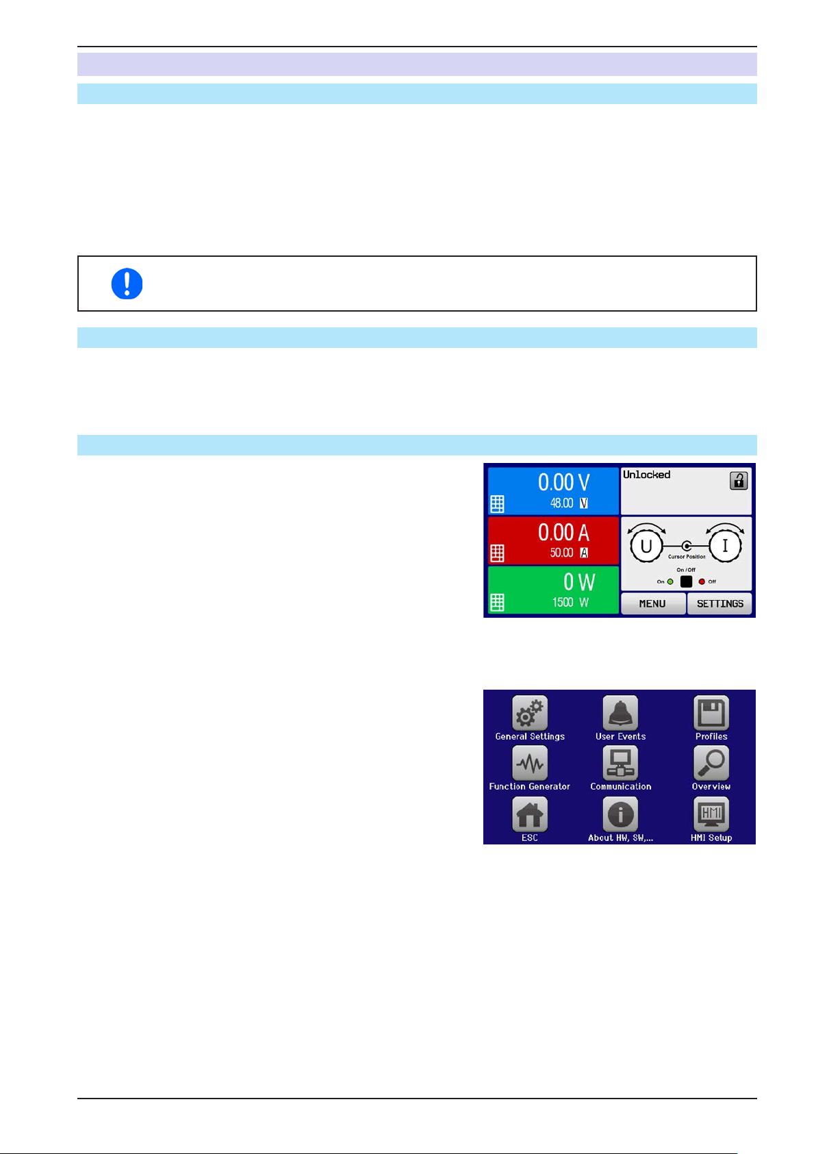
PSI 9000 2U Series
3.4 Manual operation
3.4.1 Switching on the device
The device should, as far as possible, always be switched on using the toggle switch on the front of the device.
Alternatively, this can be done using an external cutout (contactor, circuit breaker) of suitable current capacity.
After switching on, the display will rst show some device related information (model, rmware versions etc.) and
then a language selection screen for 3 seconds. A few seconds later it will show the main screen.
In setup (see section „3.4.3. Conguration via MENU“ in the second level menu “General settings” is an option
“Output after power ON” in which the user can determine the condition of the DC output after power-up. Factory
setting here is “OFF”, meaning that the DC output on power-up is always switched off. “Restore” means that the
last condition of the DC output will be restored, either on or off. All set values are always saved and restored.
For the time of the start phase the analog interface can signal undened statuses on the output
pins such as ERROR or OVP. Those signal must be ignored until the device has nished booting and is ready to work.
3.4.2 Switching off the device
On switch-off the last output condition and the most recent set values are saved. Furthermore, a PF alarm (power
failure) will be reported, but can be ignored.
The DC output is immediately switched off and after a short while fans will shut down and after another few seconds
the device will be completely powered off.
3.4.3 Conguration via MENU
The MENU serves to congure all operating parameters which
are not constantly required. These can be set by nger touch on
the MENU touch area, but only if the DC output is switched OFF.
See gure to the right.
If the DC output is switched on the settings menu will not be shown,
only status information.
Menu navigation is by nger touch. Values are set using the rotary
knobs. The assignments of the rotary knobs, if multiple values
can be set in a particular menu, is not always depicted. Following
rule for such situations: upper value -> left knob, lower value .>
right knob.
The menu structure is shown schematically on the following pages.
Some setting parameters are self-explanatory, others are not. The
latter will be explained on the pages following.
EPS Stromversorgung GmbH
Alter Postweg 101 • 86159 Augsburg
Germany
Fon: +49 821 / 570451-0
Fax: +49 821 / 570451-25
www.eps-germany.de
Page 43
Page 44
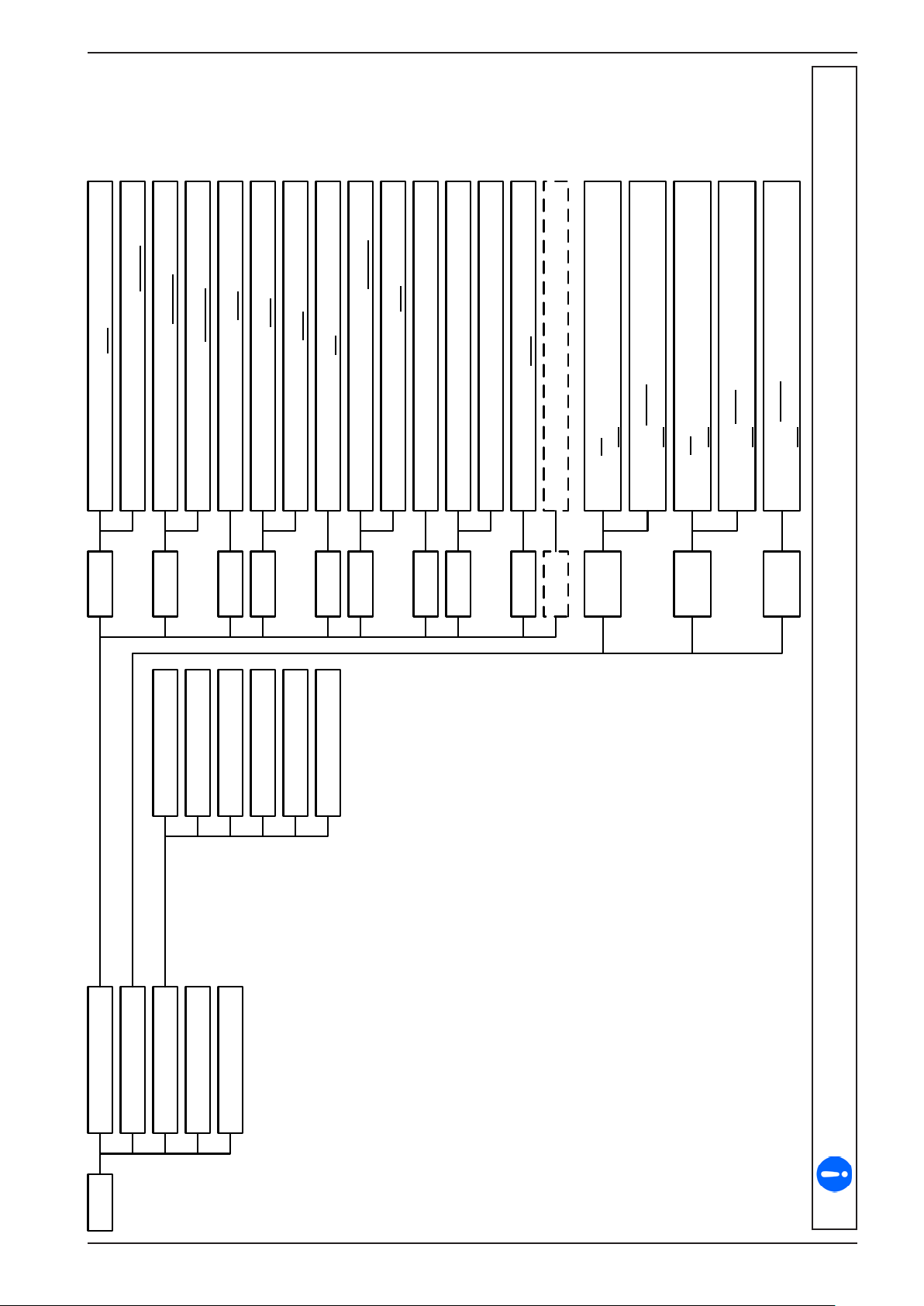
PSI 9000 2U Series
Allow remote cont rol: Yes | No
Page 1
Analog inte rfa ce Rem-SB: N orm al | Inverted
Analog interface range: 0. .. 5V | 0. .. 10V
Page 2
Default P rofile
DC output after power ON: OFF | Rest orePage 3
Analog Rem-SB a ction : DC OFF | D C ON /OF F
Page 4 DC output after PF alarm: OFF | AUTO
User Pro file 1
User Pro file 2
User Pro file 3
Enable R mode: Yes | No
DC output after remot e: OFF | AUTO
Page 5
Page 6 USB decimal point format: US | Defa ult
User Pro file 4
User Pro file 5
Log value with unit (V,A,W): Yes | No
Calibrate device: StartPage 7
Rest ar t dev ice: Rest ar t
Page 8 Rese t de vice to defaults: Start
Page 9 Master-Slave mode: OF F | MASTER | SLAVE
UVD = {0V...Unom}
Aktion = {NO | SI GNA L | WARNING |ALARM}
OVD = {0V...Unom}
Aktion = {NO | SI GNA L | WARNING |ALARM}
UCD = {0A...Inom}
Aktion = {NO | SI GNA L | WARNING |ALARM}
OCD = {0A...Inom}
Aktion = {NO | SI GNA L | WARNING |ALARM}
OPD = {0W. .. Pnom}
Aktion = {NO | SI GNA L | WARNING |ALARM}
Page 10 Repeat mas ter init .: Initialize
Eve nt U
Eve nt I
Eve nt P
User Events
Profiles
Overview
About HW, SW...
MENU Gener al Se tt ing s
EPS Stromversorgung GmbH
Alter Postweg 101 • 86159 Augsburg
Germany
Fon: +49 821 / 570451-0
Fax: +49 821 / 570451-25
www.eps-germany.de
Parameters in curly brackets describe the selectable range, underlined parameters show the default value after delivery or reset.
Page 44
Page 45
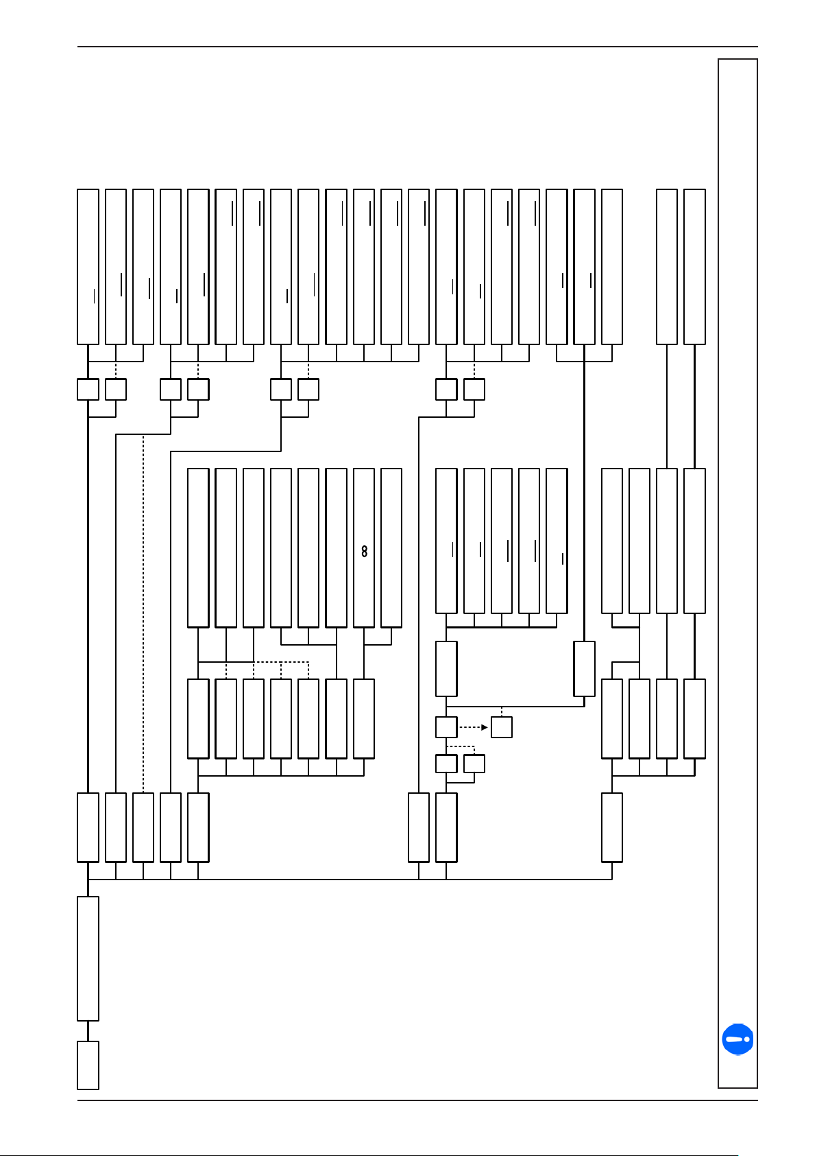
U(Off) = U(A)…Umax-U(A)
f(1/T)= 1Hz...10000HzIU(A)= 0V...Umax-Offset
U(Off) = U(A)…Umax-U(A)
t1= 0.1ms...36000s (1ms)
PSI 9000 2U Series
t2= 0.1ms...36000s (1ms)
U(A)= 0V...Umax-Offset
U(Off) = U(A)…Umax-U(A)
t1= 0.1ms...36000s (1ms)
t2= 0.1ms...36000s (1ms)
t3= 0.1ms...36000s (1ms)
t4= 0.1ms...36000s (1ms)
Ustart= 0V...Umax
Uend= 0V...Umax
t1= 0.1ms...36000s (1ms)
t2= 0.1ms...36000s (1ms)
Ue(DC)= 0V...Umax
Seq.time= 1ms...36000s
SAVE to USB
SAVE to USB
U
U
I
Ustart= 0V...Umax
Uend= 0V...Umax
DIN Sequence 1
DIN Sequence 2
Seq.time= 0.1ms...36000s
DIN Sequence 3
I
U
U(Start/End)=0V...Umax
I(Limit)=0A...Imax
DIN Sequence 4
DIN Sequence 5
P(Limit)=0W...Pmax
DIN Sequence 5
Seq.cycles= , 0...999
DIN Repetition
I
U
Us(AC)= 0V...Umax
Ue(AC)= 0V...Umax
fs(1/T)= 0Hz...10000Hz
fe(1/T)= 0Hz...10000Hz
Angle= 0°...359° Us(DC)= 0V...Umax
I/P Limits | U/P Limits
Calc. PV table
Calc. FC table
Time t1= 0.1ms...36000s
Settings 1
01
100
I
U
Settings 2
UI Table
IU Table Load from USB
PV Table
FC Table
Sine U(A)= 0V...Umax-Offset
Triangle
Rectangle
Trapezoid
DIN 40839
MENU Function Generator
EPS Stromversorgung GmbH
Alter Postweg 101 • 86159 Augsburg
Germany
Ramp
Fon: +49 821 / 570451-0
Fax: +49 821 / 570451-25
Arbitrary
XY
www.eps-germany.de
Parameters in curly brackets describe the selectable range, underlined parameters show the default value after delivery or reset.
Dotted lines mark multiple identical parameters like with U, I for “Sine”, where U(A) changes to I(A) etc.
Page 45
Page 46
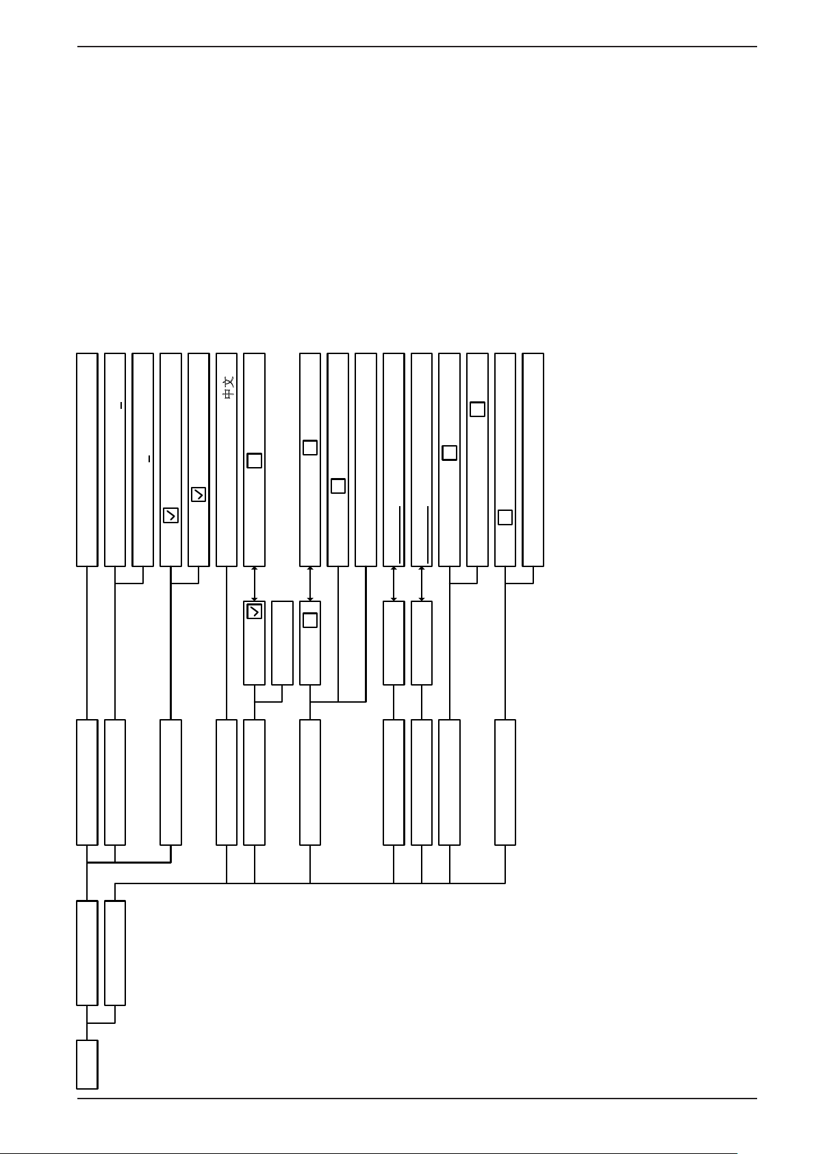
PSI 9000 2U Series
...
SC PI:
ModBus:
Timeout USB/RS232 (ms): 5. .. 65535
Timeout ETH (s): 5...65535
<interface_na me >
Com Timeout
Com Protocols
English, D eut sch, Рус ский, 中文
Language
Enable PIN:
Change user PIN: Start
Always on: Of f af te r 60 sec:
Brightness:
Back light
HMI Lock Loc k all: ON/OFF possible:
Key Sound Sound on Sound off
Alarm S o und Sound on Sound off
Altern ative sta tus page:
Sta tus page Show meter bar:
Unlo ck: S tart
Limits Lock Lock:
HMI S et up
MENU Commu nicat io n
EPS Stromversorgung GmbH
Alter Postweg 101 • 86159 Augsburg
Germany
Fon: +49 821 / 570451-0
Fax: +49 821 / 570451-25
www.eps-germany.de
Page 46
Page 47

PSI 9000 2U Series
3.4.3.1 Menu “General Settings”
Setting P. Description
Allow remote control 1 Selection “NO” means that the device cannot be remotely controlled over either
the digital or analog interfaces. If remote control is not allowed, the status will be
shown as “local” in the status area on the main display. See also section 1.9.6.1
Analog interface range 1 Selects the voltage range for the analog set inputs, actual value outputs and
reference voltage output.
• 0...5 V = corresponds to 0...100% set / actual values, reference voltage 5 V
• 0...10 V = corresponds to 0...100% set / actual values, reference voltage 10 V
See also section „3.5.4 Remote control via the analog interface (AI)“ on page
57
Analog interface Rem-SB 2 Selects how the input pin “Rem-SB” of the analog interface shall be working
regarding levels (see „3.5.4.4 Analog interface specication“ on page 58)
and logic:
• normal = Levels and function as described in the table in 3.5.4.4
• inverted = Levels and function will be inverted
Also see „3.5.4.7. Application examples“
Analog Rem-SB action 2 Selects the action on the DC output that is initiated when changing the level of
analog input “Rem-SB”:
• DC OFF = the pin can only be used to switch the DC output off
• DC AUTO = the pin can be used to switch the DC output off and on again, if
it has been switched on before at least from a different control location
DC output after power ON 3 Determines the condition of the DC output after power-up.
• OFF = DC output is always off after switching on the device.
• Restore = DC output condition will be restored to the condition prior to switch off.
DC output after PF alarm 4 Determines how the DC output shall react after a power fail (PF) alarm has
occurred:
• OFF = DC output will be switched off and remain until user action
• Auto ON = DC output will switch on again after the PF alarm cause is gone
and if it was switched on before the alarm occurred
DC output after remote 4 Determines the condition of the DC output after leaving remote control either
manually or by command.
• OFF = DC output will be always off when switching from remote to manual
• AUTO = DC output will keep the last condition
Enable R mode 5 Activates (“Yes”) or deactivates (“No”) the internal resistance control. If activated,
the resistance set value can be adjusted additionally to the other set values.
For details refer to „3.2.4. Internal resistance regulation“
USB decimal point format 6 Switches the decimal point format of values and also the CSV le separator for
USB logging and for other features where CSV le can be loaded
US = Comma separator (US standard for CSV les)
Default = Semicolon separator (german/european standard for CSV les)
Log value with unit (V,A,W) 6 CSV les generated from USB logging by default add physical units to values.
This can be deactivated by setting this option to “No”
Calibrate device 7 Touch area “Start” starts a calibration routine (see „4.3. Calibration“), but only
if the device is in U/I or U/P mode.
Reset device to defaults 8 Touch area “Start” will initiate a reset of all settings (HMI, prole etc.) to default
values, as shown in the menu structure diagrams on the previous pages
Restart device 8 Will initiate a warm start of the device
Master-slave mode 9 Selecting “MASTER” or “SLAVE” enables the master-slave mode (MS) and
set sthe selected position for the unit in the MS sytem. Default setting: OFF.
This applies for the digital MS bus, the analog Share bus and two-quadrants
operation. For details see sections „3.11.1. Parallel operation in master-slave
mode (MS)“ and „3.11.4. Two quadrant operation (2QO)“.
EPS Stromversorgung GmbH
Alter Postweg 101 • 86159 Augsburg
Germany
Fon: +49 821 / 570451-0
Fax: +49 821 / 570451-25
www.eps-germany.de
Page 47
Page 48
PSI 9000 2U Series
Setting P. Description
Repeat master init. 10 Touch area “Initialize” will repeat the initialisation of the master-slave system
in case the automatic enumeration of the slave units by the master is once
unsuccessful so the system would have less total power than expected or has
to be repeated manually in case the master unit couldn’t detect a missing slave
3.4.3.2 Menu “User Events”
See „3.6.2.1 User dened events“ on page 62.
3.4.3.3 Menu “Proles”
See „3.9 Loading and saving a user prole“ on page 64.
3.4.3.4 Menu “Overview”
This menu page displays an overview of the set values (U, I, P or U, I, P, R) and alarm settings as well as settings
limits. These can only be displayed, not changed.
3.4.3.5 Menu “About HW, SW...”
This menu page displays an overview of device relevant data such as serial number, article number etc., as well as
an alarm history which lists the number of device alarms that probably occurred since the device has been powered.
3.4.3.6 Menu “Function Generator”
See „3.10 The function generator“ on page 65.
3.4.3.7 Menu “Communication”
This submenu offers settings for digital communication via the optional or built-in interface. The touch area for the
installed interface module or the optional GPIB port opens one or more settings pages, depending on the interface
in use. There is furthermore an adjustable communication timeout, to make it possible to successfully transfer
fragmented messages (data packets) using higher values. In the screen for “Com Protocols” you can enable both
or disable one of the two supported communication protocols, ModBus and SCPI. This can help to avoid mixing
both protocols and to receive unreadable messages, for example when expecting a SCPI response and getting a
ModBus response instead.
For all Ethernet interfaces with two ports: „P1“ is related to port 1 and „P2“ to port 2, like printed
on the module face. Two-port interfaces will use one IP only.
IF Level 1 Description
Node Address
Function Tag
Selection of the Probus or node address of the device within range 1...125 via direct input
String input box for a user-denable text which describes the Probus slave function tag.
Max. length: 32 characters
Location Tag
String input box for a user-denable text which describes the Probus slave location tag.
Max. length: 22 characters
Installation Date
Probus DP
Description
String input box for a user-denable text which describes the Probus slave installation
date tag. Max. length: 40 characters
String input box for a user-denable text which describes the Probus slave.
Max. length: 54 characters
IF Level 1 Description
-
The baud rate is selectable, other serial settings can’t be changed and are dened like
this: 8 data bits, 1 stop bit, parity = none
RS232
Baud rates: 2400, 4800, 9600, 19200, 38400, 57600, 115200
IF Level 1 Description
Node Address Adjustment of the GPIB node address (only with option 3W installed) in the range 1...30
GPIB
EPS Stromversorgung GmbH
Alter Postweg 101 • 86159 Augsburg
Germany
Fon: +49 821 / 570451-0
Fax: +49 821 / 570451-25
www.eps-germany.de
Page 48
Page 49
PSI 9000 2U Series
IF Level 1 Level 2 Level 3 Description
IP Settings 1 DHCP The IF allows a DHCP server to allocate an IP address, a subnet
mask and a gateway. If no DHCP server is in the network then
network parameters will be set as dened in item “Manual”
Manual IP address This option is activated by default. An IP address can be manu-
ally allocated.
Gateway Here a gateway address can be allocated if required..
Subnet mask Here a subnet mask can be dened if the default subnet mask
is not suitable.
DNS address 1
DNS address 2
Port Range: 0...65535. Default ports:
IP Com
AUTO Settings for the Ethernet port such as transmission speed are
Settings P1
IP Com
Ethernet / ModBus-TCP, 1 & 2 Port
Settings P2
Manual Half duplex Manual selection for transmission speed (10MBit/100MBit) and
Full duplex
10MBit
100MBit
Host name Free choice of host name (default: Client)
Domain name Free choice of Domain (default: Workgroup)
TCP Keep-Alive Enable TCP keep-alive
Here the addresses of the rst and second Domain Name Servers (DNS) can be dened, if needed.
5025 = Modbus RTU (all Ethernet interfaces)
Reserved ports which must not be set with this parameter:
502 = Modbus TCP (Modbus-TCP interface only)
other typical reserved ports
set automatically.
duplex mode (full/half). It is recommended to use the “AUTO”
option and only revert to “Manual” if these parameters fail.
IF Level 1 Level 2 Level 3 Description
IP Settings
DHCP The IF allows a DHCP server to allocate an IP address, a subnet
mask and a gateway. If no DHCP server is in the network then
network parameters will be set as dened in point “Manual”
Manual IP address This option is activated by default. An IP address can be manu-
ally allocated.
Gateway Here a gateway address can be allocated if required..
Subnet mask Here a subnet mask can be dened if the default subnet mask
is not suitable.
DNS address 1
DNS address 2
Host name
Domain name
Function Tag
Pronet/IO, 1 & 2 Port
Location Tag
Here the addresses of the rst and second Domain Name Servers (DNS) can be dened, if needed.
Free choice of host name (default: Client)
Free choice of Domain (default: Workgroup)
String input box for a user-denable text which describes the
Pronet slave function tag. Max. length: 32 characters
String input box for a user-denable text which describes the
Pronet slave location tag. Max. length: 22 characters
Station Name
String input box for a user-denable text which describes the
Pronet station name. Max. length: 54 characters
Description
String input box for a user-denable text which describes the
Probus slave. Max. length: 54 characters
Installation Date
String input box for a user-denable text which describes the
Probus slave installation date tag. Max. length: 40 characters
EPS Stromversorgung GmbH
Alter Postweg 101 • 86159 Augsburg
Germany
Fon: +49 821 / 570451-0
Fax: +49 821 / 570451-25
www.eps-germany.de
Page 49
Page 50

PSI 9000 2U Series
IF Ebene 1 Level 2 Level 3 Description
Base ID Setup of the CAN base ID (11 Bit or 29 Bit, hex format). Default: 0h
Baud Rate Setup of the CAN bus speed or baud rate in typical value be-
tween 10 kbps and 1Mbps. Default: 500 kbps
Termination Activates or deactivates CAN bus termination with a built-in resis-
tor. Default: OFF
Broadcast ID Setup of the CAN broadcast ID (11 Bit or 29 Bit, hex format). De-
fault: 7ffh
ID Format Selection of the CAN ID format between Base (11 Bit ID, 0h...7ffh)
and Extended (29 Bit, 0h...1fffffffh)
Cyclic
Communication
CAN
Data Length Determines the DLC (data length) of all messages sent from the
Base ID
Cyclic
Read
Base ID
Cyclic
Send
Cyclic
Read
Timing
Setup of the CAN base ID (11 Bit or 29 Bit, hex format) for cyclic read
of up to 5 object groups (see “Cyclic Read Timing”). The device
will automatically send specic object data to the IDs dened with
this setting. For more information refer to the programming guide.
Default: 100h
Setup of the CAN base ID (11 Bit or 29 Bit, hex format) for cyclic
send of the three set values for U, I and P along with status in one
single message. For more information refer to the programming
guide. Default: 200h
Status Activation/deactivation and time setting for the cyclic read of status
to the adjusted „Base ID Cyclic Read + 1“
Range: 20...5000 ms. Default: 0 (deactivated)
Actual
val.
Activation/deactivation and time setting for the cyclic read of actual
values to the adjusted „Base ID Cyclic Read + 2“
Range: 20...5000 ms. Default: 0 (deactivated)
Set val. Activation/deactivation and time setting for the cyclic read of set
values of U & I to the adjusted „Base ID Cyclic Read + 3“
Range: 20...5000 ms. Default: 0 (deactivated)
Limits 1 Activation/deactivation and time setting for the cyclic read of adjust-
ment limits of P & R to the adjusted „Base ID Cyclic Read + 4“
Range: 20...5000 ms. Default: 0 (deactivated)
Limits 2 Activation/deactivation and time setting for the cyclic read of adjust-
ment limits of P & R to the adjusted „Base ID Cyclic Read + 4“
device.
AUTO = length varies between 3 and 8 bytes, depending on object
Always 8 Bytes = length is always 8, lled up with zeros
IF Level 1 Level 2 Description
Node Address Selection of the CANopen node address in the range 1...127 via direct input
Baud Rate AUTO Automatic detection of the bus baud rate.(speed)
LSS Automatically sets baud rate and node address
CANopen
Manual Manual selection of the baud rate that is used by the CANopen interface.
Possible selections: 10 kbps, 20 kbps, 50 kbps, 100 kbps, 125 kbps, 250
kbps, 500 kbps, 800 kbps, 1Mbps (1Mbps = 1 Mbit/s, 10 kbps = 10 kbit/s)
EPS Stromversorgung GmbH
Alter Postweg 101 • 86159 Augsburg
Germany
Fon: +49 821 / 570451-0
Fax: +49 821 / 570451-25
www.eps-germany.de
Page 50
Page 51
PSI 9000 2U Series
Element Description
Com Timeout Timeout USB/RS232 (in milliseconds)
Default value: 5, Range: 5...65535
Denes the max. time between two subsequent bytes or blocks of a transferred message.
For more information about the timeout refer to the external programming documentation
“Programming ModBus & SCPI”.
Timeout ETH (in seconds)
Default value: 5, Range: 5...65535
If there was no communication between the controlling unit (PC, PLC etc.) and the device
for the adjusted time, the device will close the socket connection.
Com Protocols Enables or disables SCPI or ModBus communication protocols for the device. The change
is immediately effective after submitting it with ENTER button. Only one of both can be
disabled.
Logging Default setting: disabled
Enables/disables the “log to USB stick” feature. Once enabled, you can dene the log
interval (multiple steps, 500 ms ... 5 s) and the control method. For more refer to „3.4.10.
Recording to USB stick (logging)“.
3.4.3.8 Menu “HMI Setup”
These settings refer exclusively to the control panel (HMI).
Element Description
Language Selection of the display language between German, English (default), Russian or Chinese
Backlight The choice here is whether the backlight remains permanently on or if it should be
switched off when no input via screen or rotary knob is made for 60 s. As soon as input
is made, the backlight returns automatically. Furthermore the brightness can be selected
in 10 steps.
HMI Lock See “„3.7 Control panel (HMI) lock“ on page 63.
Limits Lock See „3.8 Limits lock“ on page 64
Key Sound Activates or deactivates sounds when touching a touch area in the display. It can usefully
signal that the action has been accepted.
Alarm Sound Activates or deactivates the additional acoustic signal of an alarm or user dened event
which has been set to “Action = ALARM”. See also „3.6 Alarms and monitoring“ on page
61.
Status page Enables/disables two display related options for the main screen with actual and set
values:
Show meter bar: in U/I/P mode, i. e. resistance mode not activated, a meter bar for
0-100% actual values of voltage, current and power is shown. See „3.4.8. The meter bars“.
Alternative status page: switches the main screen of the device with its actual and
set values of voltage, current, power and - if activated - resistance to a simpler display
with only voltage and current, plus status. See „3.4.7. Switching the main screen view“.
Default setting: both disabled
EPS Stromversorgung GmbH
Alter Postweg 101 • 86159 Augsburg
Germany
Fon: +49 821 / 570451-0
Fax: +49 821 / 570451-25
www.eps-germany.de
Page 51
Page 52
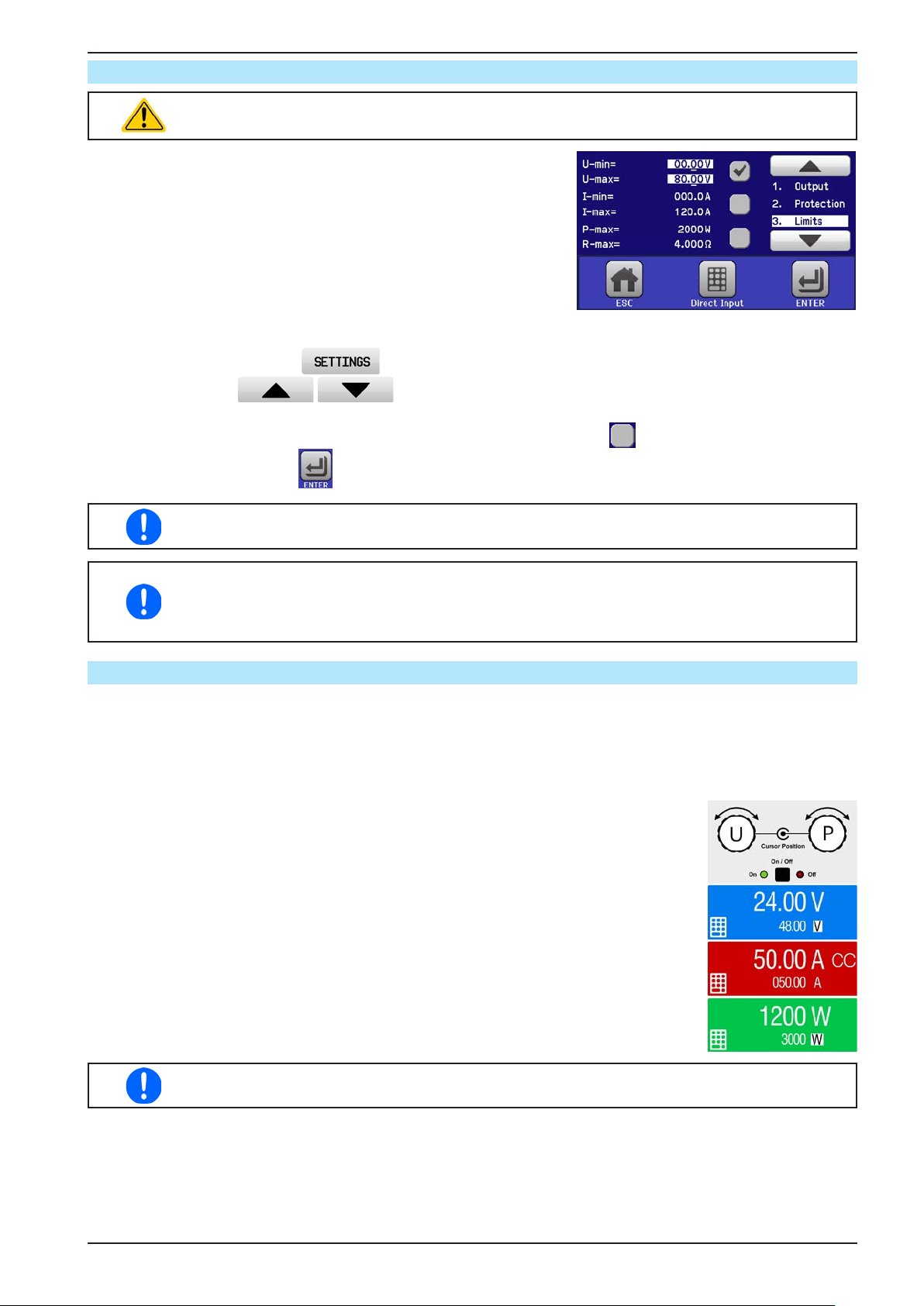
PSI 9000 2U Series
3.4.4 Adjustment limits (Limits)
Adjustment limits are only effective on the related set values, no matter if using manual
adjustment or remote control setting!
Defaults are that all set values (U, I, P, R) and the corresponding adjustment limits are adjustable from 0 to 102% of rated value.
The full range may be obstructive in some cases, especially for protection of applications against overvoltage. Therefore upper and lower
limits for current (I) and voltage (U) can be set separately, which then
limit the range of the adjustable set values.
For power (P) and resistance (R) only upper value limits can be set.
► How to congure the adjustment limits
1. On the main screen, tap to access the SETTINGS menu.
2. Tap the arrows to select “3. Limits”.
3. In each case a pair of upper and lower limits for U/I or the upper limit for P/R are assigned to the rotary
knobs and can be adjusted. Tap the selection area for another choice .
4. Accept the settings with .
The set values can be entered directly using the ten-key pad. This appears when the touch area
for direct input is tapped (bottom center)
The adjustment limits are coupled to the set values. It means, that the upper limit may not be
set lower than the corresponding set value. Example: If you wish to set the limit for the power
set value (P-max) to 1000 W while the currently adjusted power set value is 2000 W, it would
require to rst reduce the set value to 1000 W or less.
3.4.5 Changing the operating mode
In general, the manual operation of a PSI 9000 2U distinguishes between two operating modes which are tied to
set value input using the rotary knobs or ten-key pad. This assignment must be changed if one of the three set
values is to be adjusted which is currently not available.
► How to change the operating mode:
1. Unless the device is device in remote control or the panel is locked, you switch the
operation anytime. There are two options: either tap the depiction of the right-hand
knob (see gure to the right) to change its assignment between I, P and R, which
is displayed below the knob depiction, or
2. you directly tap on the coloured areas with the set values, like shown in the gure
to the right. The unit next to the set values, when inverted, indicates the assign-
ment of the knob. In the example in the gure it has U and P assigned, which
means U/P mode.
Depending on the selection the right rotary knob will be assigned different setting values,
the left knob is always assigned to the voltage.
In order to avoid constant changing of the assignments it is possible, e.g with selection U/I being
active, to change the other value P by direct input. See section 3.4.6.
The actual operating mode, while the DC output is switched on, solely depends only on the set values. For more
information see section „3.2. Operating modes“.
EPS Stromversorgung GmbH
Alter Postweg 101 • 86159 Augsburg
Germany
Fon: +49 821 / 570451-0
Fax: +49 821 / 570451-25
www.eps-germany.de
Page 52
Page 53
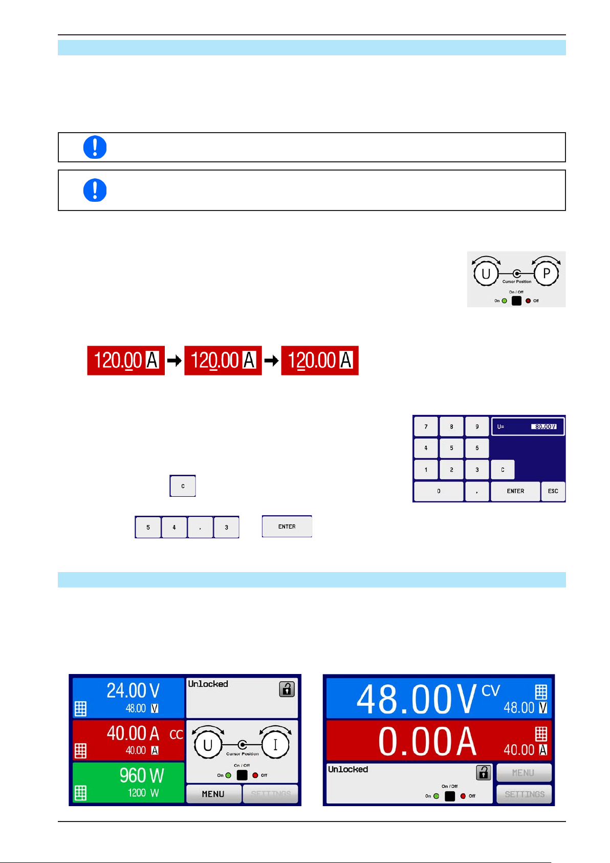
PSI 9000 2U Series
3.4.6 Manual adjustment of set values
The set values for voltage, current and power are the fundamental operating possibilities of a power supply and
hence the two rotary knobs on the front of the device are always assigned to two of the values in manual operation.
As a fourth value there is the internal resistance, for which the resistance mode (R mode) has to be activated in
the MENU rst. Refer to „3.4.3. Conguration via MENU“ and „3.2.4. Internal resistance regulation“ for details.
Set values can be entered manually in two ways: via rotary knob or direct input.
Entering a value changes it immediately and no matter if the DC output is switched on or off.
When adjusting the set values, upper or lower limits may come into effect. See section „3.4.4.
Adjustment limits (Limits)“. Once a limit is reached, the display will show a note like “Limit: U-
max” etc. for 1.5 seconds next to the adjusted value.
► How to adjust values with the rotary knobs
1. First check whether the value to be changed is assigned to one of the rotary knobs.
The main screen displays the assignment as depicted in the gure to the right.
2. If, as shown in the example, the assignment is voltage (U, left) and power (P, right),
and it is required to set the power, then the assignments can be changed by tapping
this touch area. A set of selection elds then appears.
3. After successful selection, the desired value can be set within the dened limits. Selecting a digit is done by
pushing the rotary knob which shifts the cursor right to left (digit will be underlined):
►How to adjust values via direct input:
1. In the main screen, depending on the rotary knob assignment, values
can be set for voltage (U), current (I), power (P) or resistance (R) via
direct input by tapping on the set/actual value display areas, e.g in the
uppermost area of voltage.
2. Enter the required value using the ten-key pad. Similar to a pocket
calculator the key clears the input.
Decimal values are set by tapping the point key. For example, 54.3 V
is set with and .
3. The display switches to the main page and the set values take effect..
3.4.7 Switching the main screen view
The main screen, also called status page, with its set values, actual values and device status can be switched
from the standard view mode with three or four values to a simpler mode with only voltage and current display.
The advantage of the alternative view mode is that actual values are displayed with much bigger characters, so
they read be read from a larger distance. Refer to „3.4.3.8. Menu “HMI Setup”“ to see where to switch the view
mode in the MENU. Comparison:
Standard status page Alternative status page
EPS Stromversorgung GmbH
Alter Postweg 101 • 86159 Augsburg
Germany
Fon: +49 821 / 570451-0
Fax: +49 821 / 570451-25
www.eps-germany.de
Page 53
Page 54
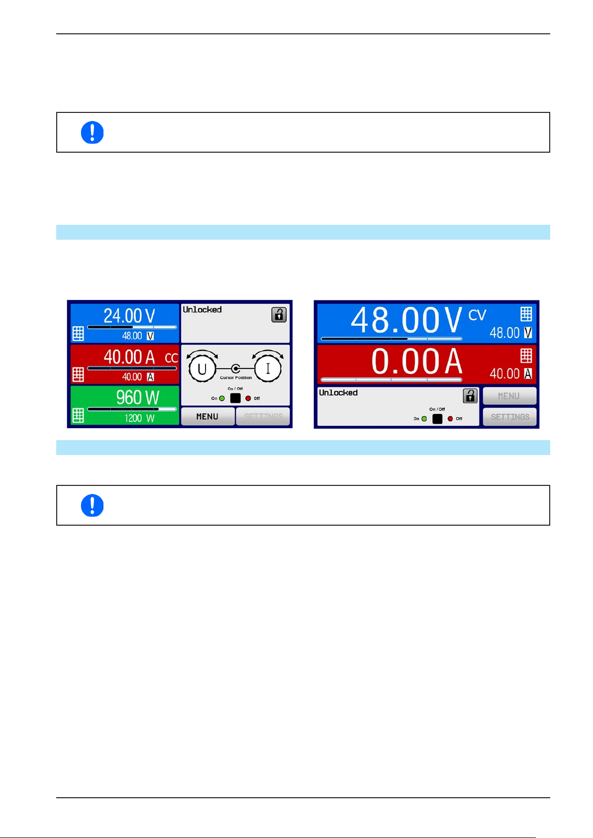
PSI 9000 2U Series
Limitations of the alternative status page:
• Set and actual values of power are not displayed and the set value of power is only indirectly accessible
• The set value of resistance is not displayed and only indirectly accessible
• No access to the settings overview (MENU button) while the DC output is on
In alternative status page mode, the set values of power and resistance are not adjustable while
the DC output is switched on. They can only be accessed and adjusted in SETTINGS while
the DC output is off.
Rules for manual handling of the HMI in alternative status page mode:
• The two rotary knobs are assigned to voltage (left knob) and current (right knob) all the time, except for menus
• Set values input is the same as in standard status page mode, with knobs or by direct input
• Regulation modes CP and CR are displayed alternatively to CC at the same position
3.4.8 The meter bars
Additionally to the actual values being displayed as numbers, a meter bar for U, I and P can be enabled in the
MENU. The meter bars remain hidden as long as resistance mode, i. e. U/I/R is activated. Refer to „3.4.3.8. Menu
“HMI Setup”“ to see where to enable the meter bars in the MENU. Depiction:
Standard status page with meter bar Alternative status page with meter bar
3.4.9 Switching the DC output on or off
The DC output of the device can be manually or remotely switched on and off. This can be restricted in manual
operation by the control panel being locked.
Switching the DC output on during manual operation or digital remote control can be disabled by
pin REM-SB of the built-in analog interface. For more information refer to 3.4.3.1 and example
a) in 3.5.4.7.
► How to manually switch the DC output on or off
1. As long as the control panel is not fully locked press the button ON/OFF. Otherwise you are asked to dis-
able the HMI lock rst.
2. This button toggles between on and off, as long as a change is not restricted by an alarm or the device is
locked in “remote”. The current condition is displayed as “Output ON” or “Output OFF”.
► How to remotely switch the DC output on or off via the analog interface
1. See section “„3.5.4 Remote control via the analog interface (AI)“ on page 57.
► How to remotely switch the DC output on or off via the digital interface
1. See the external documentation “Programming Guide ModBus & SCPI” if you are using custom software,
or refer to the external documentation from LabView VIs or other software provided by the manufacturer.
EPS Stromversorgung GmbH
Alter Postweg 101 • 86159 Augsburg
Germany
Fon: +49 821 / 570451-0
Fax: +49 821 / 570451-25
www.eps-germany.de
Page 54
Page 55
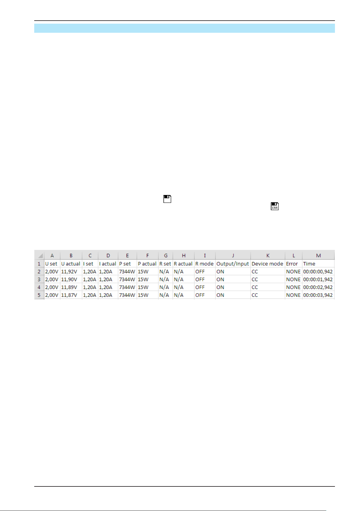
PSI 9000 2U Series
3.4.10 Recording to USB stick (logging)
Device data can be recorded to USB stick (2.0 / 3.0 may work, but not all vendors are supported) anytime. For
specications of the USB stick and the generated log les refer to section „1.9.6.5. USB port (front side)“.
The logging stores les of CSV format on the stick. The layout of the log data is the same as when logging via PC
with software EPS Power Control. The advantage of USB logging over PC logging is the mobility and that no PC
is required. The logging feature just has to be activated and congured in the MENU.
3.4.10.1 Conguration 1
Also see section 3.4.3.7. After USB logging has been enabled and the parameters “Logging interval” and “Start/
Stop” have been set, logging can be started anytime from within the MENU or after leaving it, depends on the
selected start/stop mode.
3.4.10.2 Conguration 2
Also see section 3.4.3.1. There are additional settings for the CSV le itself as generated by the USB logging feea-
tures. You can switch the column separator format between german/european standard (“Default”) or US american
standard (“US”). The other option is used to deactivate the physical unit that is added by default to every values
in the log le. Deactivating this option simplies the CSV le processing in MS Excel.
3.4.10.3 Handling (start/stop)
With setting “Start/stop with DC output ON/OFF” logging will start each time the DC output of the device is
switched on, no matter if manually with the front button “On/Off” or remotely via analog or digital interface. With
setting “Manual start/stop” it is different. Logging is then started and stopped only in the MENU, in the logging
conguration page.
Soon after logging has been started, the symbol indicates the ongoing logging action. In case there is an error
while logging, such as USB stick full or removed, it will be indicated by another symbol ( ). After every manual
stop or switching the DC output off the logging is stopped and the log le closed.
3.4.10.4 Log le format
Type: text le in german/european or US american CSV format (depending on the selected setting)
Layout (default german format shown):
Legend:
U set / I set / P set / R set: Set values
U actual / I actual / P actual / R actual: Actual values
Error: device alarms
Time: elapsed time since logging start
Device mode: actual regulation mode (also see „3.2. Operating modes“)
Important to know:
• R set and R actual are only recorded if UIR mode is active (refer to section 3.4.5)
• Unlike the logging on PC, every log start here creates a new log le with a counter in the le name, starting
generally with 1, but minding existing les
3.4.10.5 Special notes and limitations
• Max. log le size (due to FAT32 formatting): 4 GB
• Max. number of log les in folder HMI_FILES: 1024
• With setting “Start/stop with DC output ON/OFF”, the logging will also stop on alarms or events with action
“Alarm”, because they switch off the DC output
• With setting “Manual start/stop” the device will continue to log even on occurring alarms, so this mode can be
used to determine the period of temporary alarms like OT or PF
EPS Stromversorgung GmbH
Alter Postweg 101 • 86159 Augsburg
Germany
Fon: +49 821 / 570451-0
Fax: +49 821 / 570451-25
www.eps-germany.de
Page 55
Page 56
PSI 9000 2U Series
3.5 Remote control
3.5.1 General
Remote control is possible via the built-in analog or USB port or via one of the optional interface modules (only
with standard models) or via the GPIB port (only with option 3W installed). Important here is that only the analog
or one digital interface can be in control. It means that if, for example, an attempt were to be made to switch to
remote control via the digital interface whilst analog remote control is active (Pin Remote = LOW) the device would
report an error via the digital interface. In the opposite direction, a switch-over via Pin Remote would be ignored.
In both cases, however, status monitoring and reading of values are always possible.
3.5.2 Control locations
Control locations are those locations from where the device can be controlled. Essentially there are two: at the
device (manual operation) and external (remote control). The following locations are dened:
Displayed location Description
- If neither of the other locations is displayed then manual control is active and access from
the analog and digital interfaces is allowed. This location is not explicitly displayed
Remote Remote control via any interface is active
Local Remote control is locked, only manual operation is allowed.
Remote control may be allowed or inhibited using the setting “Allow remote control” (see „3.4.3.1. Menu “General
Settings”“). In inhibited condition the status “Local” will be displayed top right. Activating the lock can be useful if
the device is remotely controlled by software or some electronic device, but it is required to make adjustments at
the device or deal with emergency, which would not be possible remotely.
Activating condition “Local” causes the following:
• If remote control via the digital interface is active (“Remote”), then it is immediately terminated and in order to
continue remote control once “Local” is no longer active, it has to be reactivated at the PC
• If remote control via the analog interface is active (“Remote”), then it is temporarily interrupted until remote control
is allowed again by deactivating “Local”, because pin “Remote” continues to signal “remote control = on”, unless
this has been changed during the “Local” period
3.5.3 Remote control via a digital interface
3.5.3.1 Selecting an interface
The standard models of series PSI 9000 2U support, in addition to the built-in USB port, the following optional ly
available interface modules:
Short ID Type Ports Description*
IF-AB-CANO
IF-AB-RS232
IF-AB-PBUS
IF-AB-ETH1P
IF-AB-PNET1P
IF-AB-MBUS
IF-AB-ETH2P
IF-AB-MBUS2P
IF-AB-PNET2P
IF-AB-CAN
* For technical details of the various modules see the extra documentation “Programming Guide Modbus & SCPI”
Models with option 3W installed offer an additional pre-installed GPIB port next to the default USB port.
CANopen 1 CANopen slave with generic EDS
RS232 1 Standard RS232, serial
Probus 1 Probus DP-V1 slave
Ethernet 1 Ethernet TCP
ProNet 1 Pronet DP-V1 slave
ModBus TCP 1 ModBus TCP protocol via Ethernet
Ethernet 2 Ethernet TCP, with switch
ModBus TCP 2 ModBus TCP protocol via Ethernet, with switch
ProNet 2 Pronet DP-V1 slave, with switch
CAN 1 Modied ModBus RTU via CAN
EPS Stromversorgung GmbH
Alter Postweg 101 • 86159 Augsburg
Germany
Fon: +49 821 / 570451-0
Fax: +49 821 / 570451-25
www.eps-germany.de
Page 56
Page 57
PSI 9000 2U Series
3.5.3.2 General
With the standard models of series PSI 9000 2U, one of the plug-in and retrottable modules listed in 3.5.3.1 can
be installed. It can take over remote control of the device alternatively to the built-in USB port on the back side or
analog interface. For installation see section „2.3.8. Installation of an interface module“ and separate documentation.
The modules require little or no settings for operation and can be directly used with their default conguration. All
specic settings will be permanently stored such that, after changeover between the various models, no reconguration will be necessary.
3.5.3.3 Programming
Programming details for the interfaces, the communication protocols etc. are to be found in the documentation
“Programming Guide ModBus & SCPI“ which is supplied on the included USB stick or which is available as download from the manufacturer’s website.
3.5.4 Remote control via the analog interface (AI)
3.5.4.1 General
The built-in, galvanically isolated 15-pole analog interface (short: AI) is on the rear side of the device offers the
following possibilities:
• Remote control of current, voltage, power and internal resistance *
• Remote status monitoring (CC/CP, CV)
• Remote alarm monitoring (OT, OVP, PF)
• Remote monitoring of actual values
• Remote on/off switching of the DC output
Setting the set values of voltage, current and power via the analog interface must always be done concurrently.
It means, that for example the voltage can’t be given via the AI and current and power set by the rotary knobs, or
vice versa. The internal resistance set value can additionally be adjusted.
The OVP set value and other supervision (events) and alarm thresholds cannot be set via the AI and therefore
must be adapted to the given situation before the AI is going to be in control. Analog set values can be supplied
by an external voltage or generated from the reference voltage on pin 3. As soon as remote control via the analog
interface is activated, the displayed set values will be those provided by the interface.
The AI can be operated in the common voltage ranges 0...5 V and 0...10 V, both representing 0...100% of the
nominal value. The selection of the voltage range can be done in the device setup. See section „3.4.3. Congura-
tion via MENU“ for details. The reference voltage sent out from pin 3 (VREF) will be adapted accordingly:
0-5 V: Reference voltage = 5 V, 0...5 V set value signal for VSEL, CSEL, PSEL and RSEL correspond to 0...100%
nominal value, 0...100% actual values correspond to 0...5 V at the actual value outputs CMON and VMON.
0-10 V: Reference voltage = 10 V, 0...10 V set value signal for VSEL, CSEL, PSEL and RSEL correspond to 0...100%
nominal values, 0...100% actual values correspond to 0...10 V at the actual value outputs CMON and VMON.
Input of excess signals (e.g. >5 V in selected 5 V range or >10 V in the 10 V range) are clipped by the device by
setting the corresponding set value to 100%.
Before you begin, please read these important notes about the use of the interface:
After powering the device and during the start phase the AI signals undened statuses on the
output pins such as ERROR or OVP. Those must be ignored until is ready to work.
• Analog remote control of the device must be activated by switching pin “REMOTE” (5) rst. Only exception is
pin REM-SB, which can be used independently since KE rmware version 2.07
• Before the hardware is connected that will control the analog interface, it shall be checked that it can’t provide
voltage to the pins higher than specied
• Set value inputs, such as VSEL, CSEL, PSEL and RSEL (if R mode is activated), must not be left unconnected
(i.e. oating) during analog remote control. In case any of the set values is not used for adjustment, it can be tied
to a dened level or connected to pin VREF (solder bridge or different), so it gives 100%
The analog interface is galvanically separated from DC output. Therefore avoid to connect any
ground of the analog interface to the DC- or DC+ output!
* Unless the device has not already been delivered with KE rmware version 2.10 or higher, the internal resistance mode requires a hardware modication in the factory
EPS Stromversorgung GmbH
Alter Postweg 101 • 86159 Augsburg
Germany
Fon: +49 821 / 570451-0
Fax: +49 821 / 570451-25
www.eps-germany.de
Page 57
Page 58
PSI 9000 2U Series
3.5.4.2 Resolution and sample rate
The analog interface is internally sampled and processed by a digital microcontroller. This causes a limited resolution of analog steps. The resolution is the same for set values (VSEL etc.) and actual values (VMON/CMON) and
is 26214. Due to tolerances, the truly achievable resolution can be slightly lower.
There is furthermore a max. sample rate of 500 Hz. It means, the device can acquire analog set values and states
on digital pins 500 times per second.
3.5.4.3 Acknowledging device alarms
Device alarms (see 3.6.2) are always indicated in the front display and some of them are also reported as signal on
the analog interface socket (see 3.5.4.4), for example the overvoltage alarm (OV), which is considered as critical.
In case of a device alarm occurring during remote control via analog interface, the DC output will be switched off the
same way as in manual control. While some alarms, like overtemperature can be monitored via the corresponding
pin of the interface other alarms, like overpower can’t. Those could only be monitored and detected via the actual
values of voltage and current being all zero contrary to the set values.
Some device alarms (OVP, OCP and OPP) have to be acknowledged (see „3.6.2. Device alarm and event han-
dling“.) Acknowledgement during analog remote control is done with pin REM-SB switching the DC output off and
on again, means a HIGH-LOW-HIGH edge (min. 50ms for LOW), when using the default level setting for this pin.
3.5.4.4 Analog interface specication
Pin Name Type* Description Levels Electrical specication
1 VSEL AI Set voltage value
2 CSEL AI Set current value
0…10 V or. 0...5 V correspond
to 0..100% of U
Nom
0…10 V or. 0...5 V correspond
to 0..100% of I
Nom
3 VREF AO Reference voltage 10 V or 5 V
4 DGND POT
5 REMOTE DI
6 OT / PF DO
7 RSEL
(1
8 PSEL AI Set power value
9 VMON AO Actual voltage
10 CMON AO Actual current
11 AGND POT
12 R-ACTIVE DI R mode on / off
Ground for all digital signals
Switching internal /
remote control
Overheating or
power fail*** alarm
Set internal resist-
AI
ance value
Ground for all
analog signals
Remote = LOW, U
Internal = HIGH, U
Low
High
<1 V
>4 V
Internal = Open
Alarm= HIGH, U
No Alarm = LOW, U
High
> 4 V
<1 V
Low
0…10 V or. 0...5 V correspond
to 0..100% of R
Max
0…10 V or. 0...5 V correspond
to 0..100% von P
Nom
0…10 V or. 0...5 V correspond
to 0..100% von U
Nom
0…10 V or. 0...5 V correspond
to 0..100% von I
On = LOW, U
Off = HIGH, U
Low
High
Nom
<1 V
>4 V
Off = Open
DC output OFF
13 REM-SB DI
(DC output ON)
(ACK alarms ****)
14 OVP DO Overvoltage alarm
15 CV DO
* AI = Analog Input, AO = Analog Output, DI = Digital Input, DO = Digital Output, POT = Potential ** Internal Vcc approx. 10 V
*** Mains blackout, mains undervoltage or PFC error **** Only during remote control ***** The error of a set value input adds to the general error of the
related value on the DC output of the device
1) Unless the device has not already been delivered with KE rmware 2.10 or higher, using resistance mode via analog interface rst requires hardware retrot-
ting from the manufacturer
Constant voltage
regulation active
Off = LOW, U
On= HIGH, U
Low
High
<1 V
>4 V
On = Open
Alarm OV = HIGH, U
No alarm OV = LOW, U
CV = LOW, U
CC/CP/CR = HIGH, U
Low
High
<1 V
> 4 V
Low
High
Accuracy 0-5 V range: < 0.4% *****
Accuracy 0-10 V range: < 0.2% *****
Input impedance Ri >40 k...100 k
Tolerance < 0.2% at I
= +5 mA
max
Short-circuit-proof against AGND
For control and status signals.
Voltage range = 0…30 V
I
= -1 mA bei 5 V
Max
U
LOW to HIGH typ.
= 3 V
Rec’d sender: Open collector against DGND
Quasi open collector with pull-up against Vcc **
With 5 V on the pin max. ow +1 mA
I
= -10 mA at U
Max
U
= 30 V
Max
Short-circuit-proof against DGND
= 0,3 V
CE
Accuracy 0-5 V range: < 0.4% *****
Accuracy 0-10 V range: < 0.2% *****
Input impedance Ri >40 k...100 k
Accuracy < 0.2% at I
= +2 mA
Max
Short-circuit-proof against AGND
For -SEL, -MON, VREF Signals
Voltage range = 0…30 V
I
= -1 mA bei 5 V
Max
U
LOW to HIGH typ.
= 3 V
Rec’d sender: Open collector against DGND
Voltage range = 0…30 V
I
= +1 mA at 5 V
Max
Rec’d sender: Open collector against DGND
Quasi open collector with pull-up against Vcc **
<1 V
With 5 V on the pin max. ow +1 mA
I
= -10 mA at U
Max
Short-circuit-proof against DGND
>4 V
= 0,3 V, U
CE
Max
= 30 V
EPS Stromversorgung GmbH
Alter Postweg 101 • 86159 Augsburg
Germany
Fon: +49 821 / 570451-0
Fax: +49 821 / 570451-25
www.eps-germany.de
Page 58
Page 59
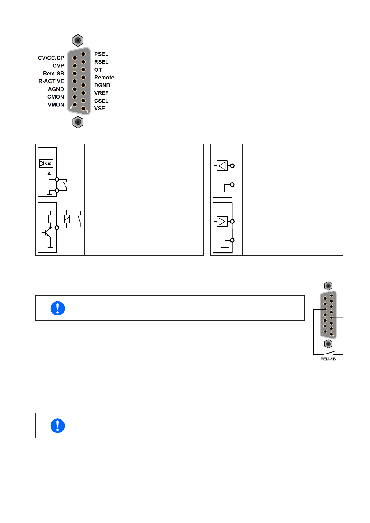
3.5.4.5 Overview of the Sub-D Socket
3.5.4.6 Simplied diagram of the pins
PSI 9000 2U Series
+
Digital Input (DI)
It requires to use a switch with low resist-
V~0.5
ance (relay, switch, circuit breaker etc.) in
Analog Input (AI)
High resistance input (impedance
>40 kΩ....100 kΩ) for an OA circuit.
order to send a clean signal to the DGND.
AGND
+10V
4.7k
12V
Digital Output (DO)
A quasi open collector, realised as high
V~2
resistance pull-up against the internal supply. In condition LOW it can carry no load,
merely switch, as shown in the diagram
AGND
Analog Output (AO)
Output from an OA circuit, with low
impedance. See specications table
above.
with a relay as example.
3.5.4.7 Application examples
a) Switching the DC output with pin “REM-SB”
A digital output, e.g. from a PLC, may be unable to cleanly pull down the pin as
it may not be of low enough resistance. Check the specication of the controlling
application. Also see pin diagrams above.
In remote control, pin REM-SB is be used to switch the DC output of the device on and off. Standalone operation of this pin can be used as well, but requires to have switched the DC output on
before using the pin to switch off and later on again.
It is recommended that a low resistance contact such as a switch, relay or transistor is used to switch
the pin to ground (DGND).
Following situations can occur:
• Remote control has been activated
During remote control via analog interface, only pin “REM-SB” determines the states of the DC output, according
to the levels denitions in 3.5.4.4. The logical function and the default levels can be inverted by a parameter in the
setup menu of the device. See 3.4.3.1.
If the pin is unconnected or the connected contact is open, the pin will be HIGH. With parameter
“Analog interface REM-SB” being set to “normal”, it requests “DC output on”. So when activating
remote control, the DC output will instantly switch on.
EPS Stromversorgung GmbH
Alter Postweg 101 • 86159 Augsburg
Germany
Fon: +49 821 / 570451-0
Fax: +49 821 / 570451-25
www.eps-germany.de
Page 59
Page 60
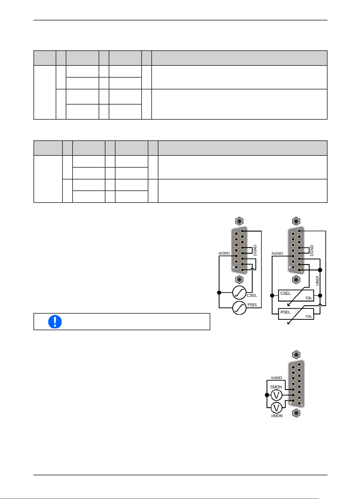
PSI 9000 2U Series
• Remote control is not active
In this mode of operation pin “REM-SB” can serve as lock, preventing the DC output from being switched on by
any means. This results in following possible situations:
DCoutput
is off
In case the DC output is already switched on, toggling the pin will switch the DC output off, similar to what it does
in analog remote control:
DCoutput
is on
b) Remote control of current and power
Requires remote control to be activated (Pin “Remote” = LOW)
The set values PSEL and CSEL are generated from, for example, the
reference voltage VREF, using potentiometers for each. Hence the
power supply can selectively work in current limiting or power limit-
ing mode. According to the specication of max. 5 mA for the VREF
output, potentiometers of at least 10 kΩ must be used.
The voltage set value VSEL is directly connected to VREF and will
thus be permanently 100%.
If the control voltage is fed in from an external source it is necessary to
consider the input voltage ranges for set values (0...5 V oder 0...10 V).
Pin
+
„REM-SB“
HIGH
+
LOW
HIGH
+
LOW
Pin
„REM-SB“
HIGH
LOW
HIGH
LOW
Parameter
+
„Rem-SB“
normal
+
inverted
+
inverted
+
normal
+
+
+
+
+
+
Parameter
„Rem-SB“
normal
inverted
inverted
normal
Behaviour
DC output not locked. It can be switched on by pushbutton “On/Off”
(front panel) or via command from digital interface.
DC output locked. It can’t be switched on by pushbutton “On/Off”
(front panel) or via command from digital interface. When trying to
switch on, a popup in the display resp. an error message will be
generated.
Behaviour
DC output remains on, nothing is locked. It can be switched on
or off by pushbutton or digital command.
DC output will be switched off and locked. Later it can be switched
on again by toggling the pin. During lock, pushbutton or digital
command can delete the request to switch on by pin.
Use of the input voltage range 0...5 V for 0...100%
set value halves the effective resolution.
c) Reading actual values
The AI provides the DC output values as current and voltage monitor. These can be
read using a standard multimeter or similar.
EPS Stromversorgung GmbH
Alter Postweg 101 • 86159 Augsburg
Germany
Fon: +49 821 / 570451-0
Fax: +49 821 / 570451-25
Example with external
voltage source
www.eps-germany.de
Example with
potentiometers
Page 60
Page 61
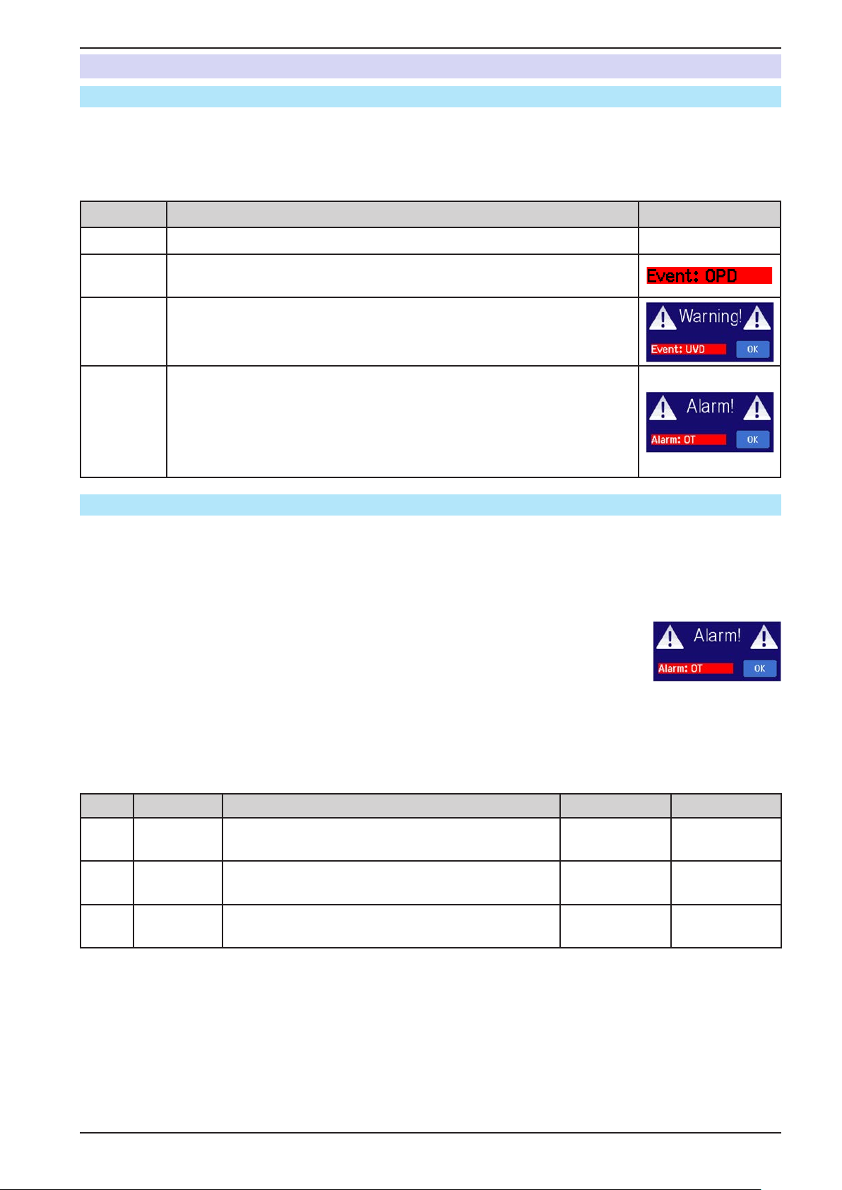
PSI 9000 2U Series
3.6 Alarms and monitoring
3.6.1 Denition of terms
There is a clear distinction between device alarms (see „3.3. Alarm conditions“) such as overvoltage protection
or overheating protection, and user dened events such as OVD (overvoltage detection). Whilst device alarms
serve to protect the device and the connected load by initially switching off the DC output, user dened events can
switch off the DC output (Action = ALARM), but can also simply give an acoustic signal to make the user aware.
The actions driven by user dened events can be selected:
Action Impact Example
NONE User dened event is disabled.
SIGNAL
On reaching the condition which triggers the event, the action SIGNAL will
show a text message in the status area of the display.
On reaching the condition which triggers the event, the action WARNING
WARNING
will show a text message in the status area of the display and pop up an
additional warning message.
On reaching the condition which triggers the event, the action ALARM will
show a text message in the status area of the display with an additional alarm
ALARM
pop-up, and additionally emit an acoustic signal (if activated). Furthermore
the DC output is switched off. Certain device alarms are also signalled to
the analog interface or can be queried via the digital interface.
3.6.2 Device alarm and event handling
A device alarm incident will usually lead to DC output switch-off. Some alarms must be acknowledged (see below),
which can only happen if the cause of the alarm is not persistent anymore. Other alarms acknowledge themselves
if the cause has vanished, like the OT and the PF alarm.
► How to acknowledge an alarm in the display (during manual control)
1. If the alarm is indicated as a pop-up, tap OK.
2. If the alarm has already been acknowledged, but is still displayed in the status area,
then rst tap the status area to display the pop-up, and then acknowledge with OK.
In order to acknowledge an alarm during analog remote control, see „3.5.4.5. Overview of the Sub-D Socket“. To
acknowledge in digital remote, refer to the external documentation “Programming ModBus & SCPI”.
Some device alarms are congurable:
Alarm Meaning Description Range Indication
OVP
OCP
OPP
OverVoltage
Protection
OverCurrent
Protection
OverPower
Protection
Triggers an alarm if the DC output voltage reaches the
dened threshold. The DC output will be switched off.
Triggers an alarm if the DC output current reaches the
dened threshold. The DC output will be switched off.
Triggers an alarm if the DC output power reaches the
dened threshold. The DC output will be switched off.
0 V...1.1*U
0 A...1.1*I
0 W...1.1*P
Nom
Nom
Display, analog
IF, digital IF
Display, digital
IF
Display, digital
Nom
IF
EPS Stromversorgung GmbH
Alter Postweg 101 • 86159 Augsburg
Germany
Fon: +49 821 / 570451-0
Fax: +49 821 / 570451-25
www.eps-germany.de
Page 61
Page 62
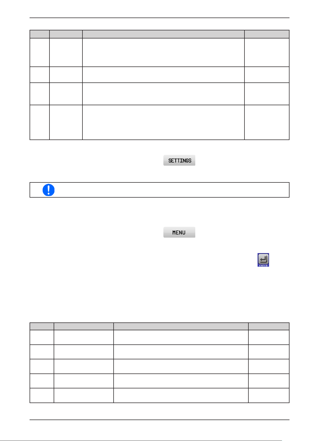
PSI 9000 2U Series
These device alarms can’t be congured and are based on hardware:
Alarm Meaning Description Indication
AC supply over- or undervoltage. Triggers an alarm if the AC supply is
PF Power Fail
out of specication or when the device is cut from supply, for example
when switching it off with the power switch. The DC output will be
switched off.
Display, digital
interface
OT
OTpre
OverTem-
perature
OverTemperature
prewarning
Triggers an alarm if the internal temperature reaches a certain limit.
The DC output will be switched off.
Triggers an event of type WARNING if the internal temperature reaches
a certain limit, lower than the one of OT. This event is intended to warn
the operator that an OT alarm is imminent.
Display, analog &
digital interface
Display, digital
interface
Triggers an alarm if the master of an initialised master-slave system
loses contact to any slave unit or if a slave has not yet been initialised
by the master. The DC output will be switched off. The alarm can be
cleared by either deactivating master-slave mode or reinitialising the
Display, digital
interface
MSP
Master-Slave
Protection
MS system.
► How to congure the device alarms
1. While the DC output is switched tap the touch area on the main screen.
2. On the right side tap the down arrow to select “2. Protect”.
3. Set the limits for the equipment alarm relevant to your application if the default value of 110% is unsuitable.
The set values can be entered using the ten-key tab. This will appear by tapping the touch area
“Direct input”.
The user also has the possibility of selecting whether an additional acoustic signal will be sounded if an alarm or
user dened event occurs.
► How to congure the alarm sound (also see “„3.4.3. Conguration via MENU“)
1. While the DC output is switched tap the touch area on the main screen
2. In the menu page, tap “HMI Settings”
3. In the following menu page, tap “Alarm Sound”
4. In the settings page tap the button to select between alarm sound on or off and conrm with .
3.6.2.1 User dened events
The monitoring functions of the device can be congured for user dened events. By default, events are deactivated (action = NONE). Contrary to device alarms, the events only work while the DC output is switched on. It
means, for instance, that you cannot detect undervoltage (UVD) anymore after switching the DC output off and
the voltage is still sinking.
The following events can be congured independently and can, in each case, trigger the actions NONE, SIGNAL,
WARNING or ALARM.
Event Meaning Description Range
UVD UnderVoltage Detection
OVD OverVoltage Detection
UCD UnderCurrent Detection
OCD OverCurrent Detection
OPD OverPower Detection
Triggers an event if the output voltage falls below the
dened threshold.
Triggers an event if the output voltage exceeds the de-
ned threshold.
Triggers an event if the output current falls below the
dened threshold.
Triggers an event if the output current exceeds the de-
ned threshold.
Triggers an event if the output power exceeds the de-
ned threshold.
0 V...U
0 V...U
0 A...I
0 A...I
0 W...P
Nom
Nom
Nom
Nom
Nom
EPS Stromversorgung GmbH
Alter Postweg 101 • 86159 Augsburg
Germany
Fon: +49 821 / 570451-0
Fax: +49 821 / 570451-25
www.eps-germany.de
Page 62
Page 63
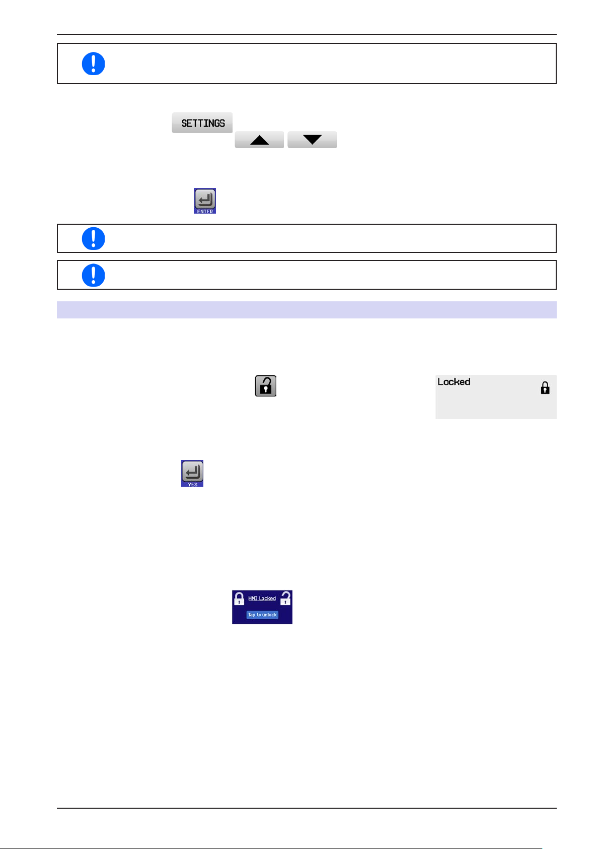
PSI 9000 2U Series
These events must not be confused with alarms such as OT and OVP which are for device
protection. User dened events can, however, if set to action ALARM, switch off the DC output
and thus protect the load, like a sensitive electronic application.
► How to congure user dened events
1. Tap the touch area on the main screen..
2. On the right side tap the arrows to select “4.1 Event U” or “4.2 Event I” or “4.3
Event P”.
3. Set the monitoring limits with the left hand rotary knob and the triggered action with the right hand knob
relevant to the application (also see „3.6.1. Denition of terms“).
4. Accept the settings with .
User events are an integral part of the actual user prole. Thus, if another user prole or the
default prole is selected and used the events could be either differently congured or not at all.
The set values can be entered using the ten-key tab. This will appear by tapping the touch area
“Direct input”.
3.7 Control panel (HMI) lock
In order to avoid the accidental alteration of a value during manual operation, the rotary knobs or the touchscreen
can be locked so that no alteration of values will be accepted without prior unlocking.
► How to lock the HMI
1. In the main page, tap the lock symbol (upper right corner).
2. In the settings page “HMI Lock” you are then asked to chose between a com-
plete HMI (“Lock all”) lock or one where the On/Off button is still usable (“ON/
OFF possible”), resp. chose to activate the additional PIN (“Enable PIN”). The
device would later request to enter this PIN every time you want to unlock the
HMI, until the PIN is deactivated again.
3. Activate the lock with . The status “Locked” as shown in the gure to the
right.
If an attempt is made to alter something whilst the HMI is locked, a requester appears in the display asking if the
lock should be disabled.
► How to unlock the HMI
1. Tap any part of the touchscreen of the locked HMI, or turn one of the rotary knobs or press the button “On/
Off” (only in “Lock all” situation).
2. This request pop-up will appear: .
3. Unlock the HMI by tapping on “Tap to unlock” within 5 seconds, otherwise the pop-up will disappear and
the HMI remains locked. In case the additional PIN code lock has been activated in the menu “HMI Lock”,
another requester will pop up, asking you to enter the PIN before it nally unlocks the HMI.
EPS Stromversorgung GmbH
Alter Postweg 101 • 86159 Augsburg
Germany
Fon: +49 821 / 570451-0
Fax: +49 821 / 570451-25
www.eps-germany.de
Page 63
Page 64
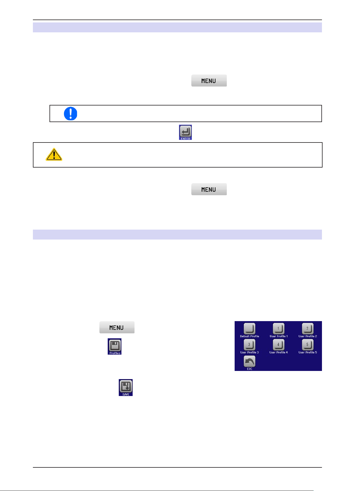
PSI 9000 2U Series
3.8 Limits lock
In order to avoid the alteration of the adjustment limits (also see „3.4.4. Adjustment limits (Limits)“) by an unprivileged user, the screen with the adjustment limit settings (“Limits”) can be locked by a PIN code. The menu pages
“3.Limits” in SETTINGS and “Proles” in MENU will then become inaccessible until the lock is removed by entering the correct PIN or in case it has been forgotten, by resetting the device as last resort.
► How to lock the “Limits”
1. While the DC output is switched off, tap the touch area on the main screen.
2. In the menu tap “Limits Lock”.
3. In the next page set the check mark for “Lock”.
The same PIN as with the HMI lock is used here. It should be set before activating the
Limits lock. See „3.2. Operating modes“
4. Activate the lock by leaving the settings page with .
Be careful to enable the lock if you are unsure what PIN is currently set. In doubt use ESC to
exit the menu page. In menu page “HMI Lock” you can dene a different PIN, but not without
entering the old one.
► How to unlock the limits settings
1. While the DC output is switched off, tap the touch area on the main screen.
2. In the menu tap “Limits Lock”.
3. In the next page tap on touch area “Unlock” and then you will be asked to enter the 4-digit PIN.
4. Deactivate the lock by entering the correct PIN and submitting with ENTER.
3.9 Loading and saving a user prole
The menu “Proles” serves to select between a default prole and up to 5 user proles. A prole is a collection of
all settings and set values. Upon delivery, or after a reset, all 6 proles have the same settings and all set values
are 0. If the user changes settings or sets target values then these create a working prole which can be saved to
one of the 5 user proles. These proles or the default one can then be switched. The default prole is read-only.
The purpose of a prole is to load a set of set values, settings limits and monitoring thresholds quickly without
having to readjust these. As all HMI settings are saved in the prole, including language, a prole change can also
be accompanied by a change in HMI language.
On calling up the menu page and selecting a prole the most important settings can be seen, but not changed.
► How to save the current values and settings as a user prole:
1. Tap the touch area on the main screen
2. In the menu page, tap .
3. In the selection screen (right) choose between user prole 1-5 in which
the settings are to be saved. The prole will then be displayed and the
values can be checked, but not changed.
4. Save using the touch area .
EPS Stromversorgung GmbH
Alter Postweg 101 • 86159 Augsburg
Germany
Fon: +49 821 / 570451-0
Fax: +49 821 / 570451-25
www.eps-germany.de
Page 64
Page 65
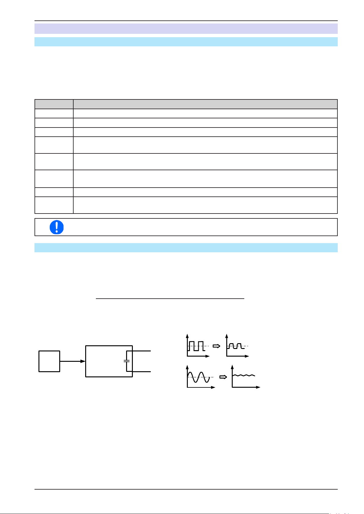
PSI 9000 2U Series
3.10 The function generator
3.10.1 Introduction
The built-in function generator (short: FG) is able to create various signal forms and apply these to the set value
of voltage or current.
The standard functions are based on an arbitrary generator and directly accessible and congurable using manual
control. For remote control, the fully customisable arbitrary generator replicates the functions with sequences
containing 8 parameters each.
The following functions are retrievable, congurable and controllable:
Function Short description
Sine wave Sine wave generation with adjustable amplitude, offset and frequency
Triangle Triangular wave signal generation with adjustable amplitude, offset, rise and fall times
Rectangular Rectangular wave signal generation with adjustable amplitude, offset and duty cycle
Trapezoid Trapezoidal wave signal generation with adjustable amplitude, offset, rise time, pulse time, fall
time, idle time
DIN 40839 Simulated automobile engine start curve according to DIN 40839 / EN ISO 7637, split into 5 curve
sequences, each with a start voltage, nal voltage and time
Arbitrary Generation of a process with up to 100 freely congurable curve points, each with a start and end
value (AC/DC), start and end frequency, phase angle and total duration
Ramp Generation of a linear rise or fall ramp with start and end values and time before and after the ramp
UI, IU
PV, FC
Table (.csv) with values for U or I, uploaded from an USB stick, as well as functions to simulate a
solar panel (PV function) or fuel cells (FC function)
Whilst R mode is activated, access to the function generator is not available.
3.10.2 General
3.10.2.1 Limitations
The function generator is not accessible, neither for manual access nor for remote control, if resistance mode (U/R
adjustment, also called UIR operation) is active.
3.10.2.2 Principle
The power supply unit cannot be considered as high power function generator, because it is only post-connected
to the FG. Thus the typical characteristics of a voltage and current source remain. Rise and fall times, caused by
capacitor charge/discharge, affect the resulting signal on the DC output. While the FG is able to generate a sine
wave with 1000 Hz or more, the power supply will never be able to follow the generated signal 1:1.
Depiction of principle: Affect of the power supply on functions:
+
FG PSI
C
DC out
--
The resulting wave form on the DC output heavily depends on the frequency of the selected wave, its amplitude
and power supply model. The effects of the power supply on the wave can only be partially compensated. A highspeed modication, like offered with option HS (see „1.9.5. Options“), can help to decrease rise and fall times.
This has a positive impact on periodic functions like rectangle or sine wave. Alternatively, the resulting wave form
on the DC output can also be improved by attaching additional load (xed & ohmic or variable & electronic).
EPS Stromversorgung GmbH
Alter Postweg 101 • 86159 Augsburg
Germany
Fon: +49 821 / 570451-0
Fax: +49 821 / 570451-25
www.eps-germany.de
Page 65
Page 66
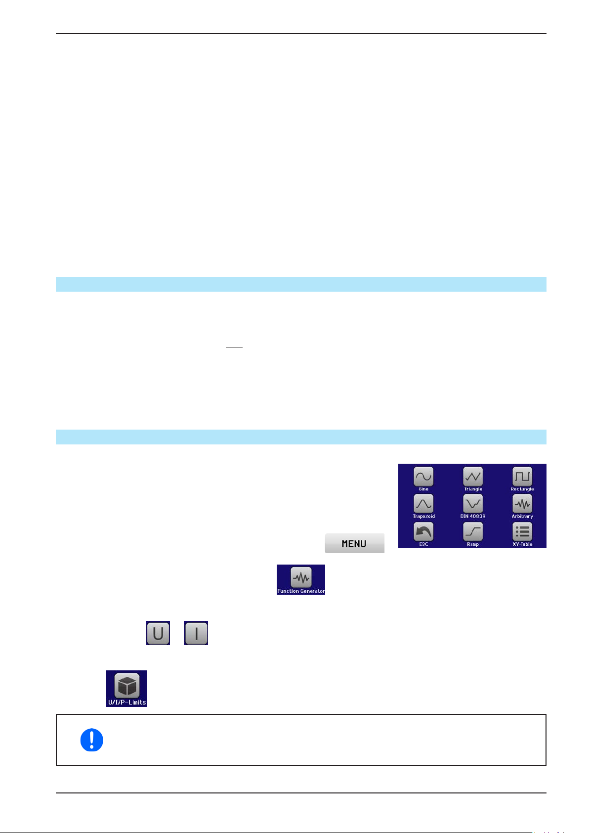
PSI 9000 2U Series
3.10.2.3 Resolution of X (Time) and Y (Amplitude)
For functions, the device can resolve 52428 steps in the effective range of 0 ... 100%. Intermediate steps to create
a linear or other rise/fall are calculated depending on the amplitude and then set.
If the amplitude is very low and the time long, only few steps will be set as otherwise many identical values will be
set one after another, generating a staircase effect.
3.10.2.4 Possible technical complications
Operation of switching mode power supplies as a voltage source can, when applying a function to the output voltage, lead to damage of the output capacitors due to continuous charging/discharging which causes overheating.
Furthermore the actual voltage progression may differ from what’s expected.
3.10.2.5 Minimum slope / maximum ramp time
When using a rising or falling offset (i.e. DC part) at functions like ramp, trapezoid, triangle and even sine wave,
a minimum slope, calculated from the rated values of voltage or current, is required or else the adjusted settings
would be neglected by the device. Calculating the minimum slope can help to determine if a certain ramp over
time can be achieved by the device or not. Example: model PSI 9080-120 2U is going to be used, with 80 V and
120 A rating. Formula: minimum slope = 0.000725 * rated value / s. For the example model it results in ΔU/Δt of
58 mV/s and ΔI/Δt of 87 mA/s. The maximum time which can be achieved with the minimum slope then calculates
as approximately 1379 seconds according to formula t
3.10.3 Method of operation
In order to understand how the function generator works and how the value settings interact, the following should
be noted:
The device operates, including in function generator mode,always with the three set values U,I and P.
The selected function can be used on one of both the values U or I, the other two are then constants and have
a limiting effect. That means if, for example, a voltage of 10 V is set for the DC output, a load is connected and
a sine wave function should operate on the current with an amplitude of 20 A and offset 20 A, then the function
generator will create a sine wave progression of current between 0 A (min) and 40 A (max), which will result in an
output power between 0 W (min) and 400 W (max).The output power, however, is limited to its set value. If this
was 300 W then, in this case, the current would be limited to 30 A and, if clamped to an oscilloscope, it could be
seen as capped at 30 A and never achieve the target of 40 A.
= rated value / min. slope.
Max
3.10.4 Manual operation
3.10.4.1 Function selection and control
Via the touchscreen one of the functions described in 3.10.10 can be called
up, congured and controlled. Selection and conguration are only possible
while the output is switched off.
► How to select a function and adjust parameters
1. While the DC output is switched off tap the touch area
on the main screen.
2. In the menu overview tap on the touch area and then on the desired function.
Note: this touch area is locked in R mode (adjustable resistance).
3. Depending on the choice of function there follows a request to which value the function generator is going
to be applied: or .
4. Adjust the parameters as you desire, like offset, amplitude and frequency for a sine wave, for example.
5. Do not forget to adjust the overall limits of voltage, current and power, which you can access with touch
area .
When entering function generator mode, those limits are reset to safe values, which can prevent
the function from working at all. For example, if you apply the selected function to the output
current, then the overall current limit should not interfere and should at least be as high as
offset + amplitude.
EPS Stromversorgung GmbH
Alter Postweg 101 • 86159 Augsburg
Germany
Fon: +49 821 / 570451-0
Fax: +49 821 / 570451-25
www.eps-germany.de
Page 66
Page 67
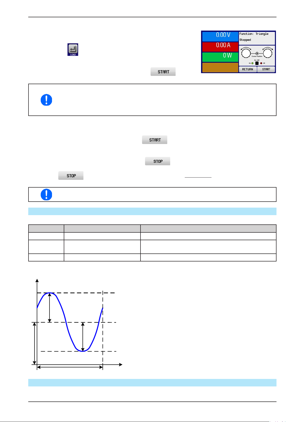
PSI 9000 2U Series
Setting the various functions is described below. After setting it up, the function can be loaded.
► How to load a function
1. After setting the values for the required signal generation, tap on the
touch area .
The device will then load the data into the internal controller and changes the
display. Shortly afterwards the static values are set (power and voltage or cur-
rent), the DC output is switched on and the touch area enabled.
Only then can the function be started.
The static values are applied to the DC output immediately after loading the function, because it
switches the DC output on automatically in order to settle the start situation. These static values
represent start and end values for the progress of the function, so that the function does not
need to start from 0. Only exception: when applying any function to the current (I), there is no
adjustable static current value, so the function would always start from 0 A.
► How to start and stop a function
1. The function can be started either by tapping or pushing the “On/Off” button, if the DC output is
currently switched off. The function then starts immediately. In case START is used while the DC output is
still switched off, the DC output will be switched on automatically.
2. The function can be stopped either by tapping or operating the “On/Off” button. However, there
is a difference:
a) The button stops only the function, the DC output remains ON with the static values.
b) The “On/Off“ button stops the function and switches off the DC output.
Device alarms such as overvoltage, overheating or power fail stops the function progress automatically and the DC output is switched off.
3.10.5 Sine wave function
The following parameters can be congured for a sine wave function:
Value Range Description
I(A), U(A) 0...(Nominal value - (Offs)) of U, I A = Amplitude of the signal to be generated
I(Offs), U(Offs) (A)...(Nominal value - (A)) of U, I Off = Offset, based on the zero point of the mathematical sine
curve, may not be smaller than the amplitude.
f (1/t) 1...10000 Hz Static frequency of the signal to be generated
Schematic diagram: Application and result:
A
Amplitude
Offset
Amplitude
A normal sine wave signal is generated and applied to
the selected set value, e.g. voltage (U). At a constant
load resistance, the output voltage and thus also the
output current will follow a sine wave.
For calculating the maximum power output the amplitude
and offset values for the current have to be added.
Example: an output voltage of 60 V is set together with
sin(I) with an amplitude of 12 A and an offset of 15 A.
The resulting maximum power output is then achieved
at the highest point of the sine wave and is (12 A + 15
A) * 60 V = 1620 W.
t
f
3.10.6 Triangular function
The following parameters can be congured for a triangular wave function:
EPS Stromversorgung GmbH
Alter Postweg 101 • 86159 Augsburg
Germany
Fon: +49 821 / 570451-0
Fax: +49 821 / 570451-25
www.eps-germany.de
Page 67
Page 68
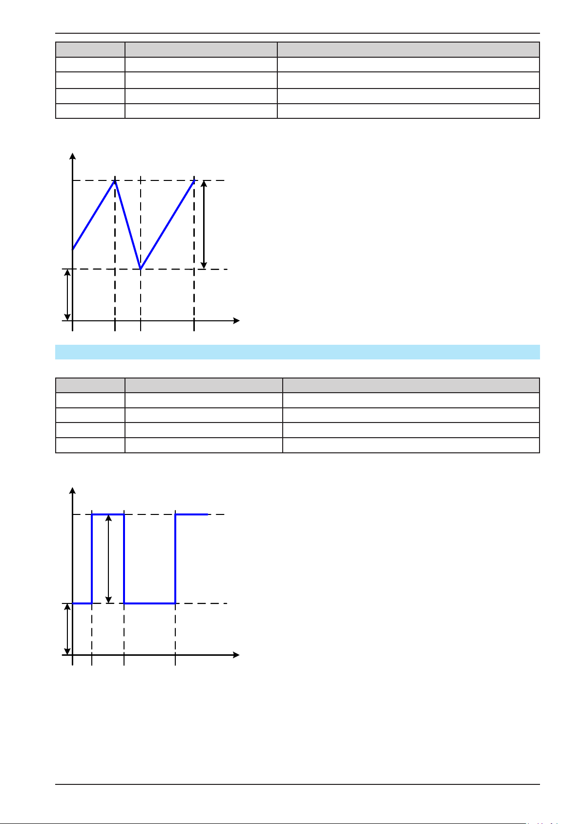
PSI 9000 2U Series
Value Range Description
I(A), U(A) 0...(Nominal value - (Offs)) of U, I A = Amplitude of the signal to be generated
I(Offs), U(Offs) 0...(Nominal value - (A)) of U, I Offs = Offset, based on the foot of the triangular wave
t1 0.1 ms...36000 s Rising edge time Δt of the triangular wave signal
t2 0.1 ms...36000 s Falling edge time Δt of the triangular wave signal
Schematic diagram: Application and result:
A
Amplitude
Offset
A triangular wave signal for output current (only effective
in current limiting) or output voltage is generated. The
positive and negative slope times can be set independently.
The offset shifts the signal on the Y-axis.
The sum of the intervals t1 and t2 gives the cycle time
and its reciprocal is the frequency.
Example: a frequency of 10 Hz is required and would
lead to periodic duration of 100 ms. This 100 ms can
be freely allocated to t1 and t2, e.g. 50 ms:50 ms (isosceles triangle) or 99.9 ms:0.1 ms (right-angled triangle
or sawtooth).
t1t2
t
3.10.7 Rectangular function
The following parameters can be congured for a rectangular wave function:
Value Range Description
I(A), U(A) 0...(Nominal value - (Offs)) von U, I A = Amplitude of the signal to be generated
I(Offs), U(Offs) 0...(Nominal value - (A)) von U, I Offs = Offset, based on the foot of the rectangular wave
t1 0.1 ms...36000 s Time (pulse width) of the upper level (amplitude)
t2 0.1 ms...36000 s Time (pause width) of the lower level (offset)
Schematic diagram: Application and result:
A
Amplitude
Offset
t1 t2
t
A rectangular or square wave signal for output current
(only effective in current limiting) or output voltage is
generated. The intervals t1 and t2 dene how long the
value of the amplitude (pulse) and how long the value
of the offset (pause) are effective.
The offset shifts the signal on the Y-axis.
Intervals t1 and t2 can be used to dene a duty cycle. The
sum of t1 and t2 gives the cycle time and its reciprocal
is the frequency.
Example: a rectangular wave signal of 25 Hz and a
duty cycle of 80% are required. The sum of t1 and t2,
the period, is 1/25 Hz = 40 ms. For a duty cycle of 80%
the pulse time (t1) is 40 ms*0.8 = 32 ms and the pause
time (t2) is 8 ms.
EPS Stromversorgung GmbH
Alter Postweg 101 • 86159 Augsburg
Germany
Fon: +49 821 / 570451-0
Fax: +49 821 / 570451-25
www.eps-germany.de
Page 68
Page 69
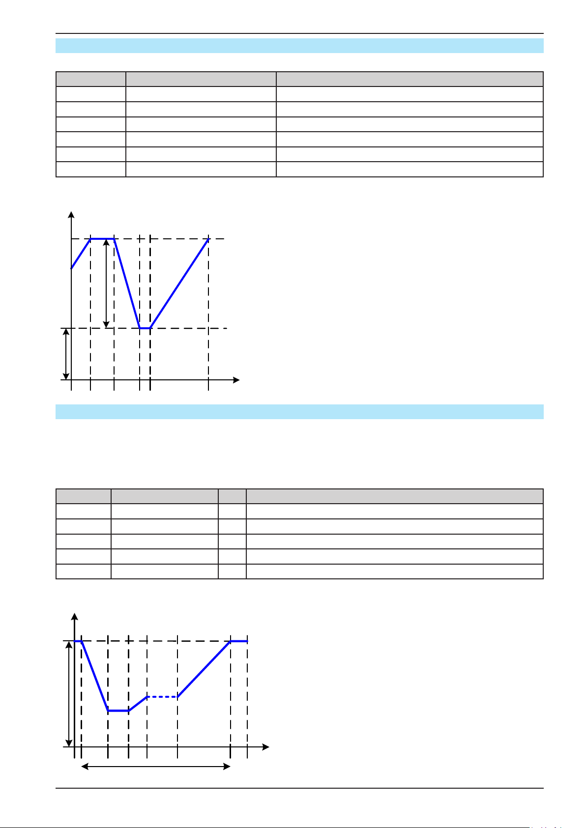
PSI 9000 2U Series
Offset
3.10.8 Trapezoidal function
The following parameters can be congured for a trapezoidal curve function:
Value Range Description
I(A), U(A) 0...(Nominal value - (Offs)) of U, I A = Amplitude of the signal to be generated
I(Offs), U(Offs) 0...(Nominal value - (A)) of U, I Offs = Offset, based on the foot of the trapezium
t1 0.1 ms...36000 s Time for the positive slope of the trapezoidal wave signal.
t2 0.1 ms...36000 s Time for the top value of the trapezoidal wave signal.
t3 0.1 ms...36000 s Time for the negative slope of the trapezoidal wave signal.
t4 0.1 ms...36000 s Time for the base value (offset) of the trapezoidal wave signal
Schematic diagram: Application and result:
A
Amplitude
Here a trapezoidal signal can be applied to a set value
of U or I. The slopes of the trapezium can be different
by setting different times for rise and fall.
The periodic duration and repetition frequency are the
result of four time elements. With suitable settings the
trapezium can be deformed to a triangular or rectangular
wave. It has, therefore, universal use.
t1t2 t3 t4
t
3.10.9 DIN 40839 function
This function is based on the curve dened in DIN 40839 / EN ISO 7637 (test impulse 4), and is only applicable
to voltage. It shall replicate the progress of automobile battery voltage during engine starting. The curve is divided
into 5 sequences (see diagram below) which each have the same parameters. The standard values from the DIN
are set already as default values for the ve sequence points.
The following parameters can be congured for the DIN40839 function:
Value Range Seq Description
Ustart 0...Nominal value of U 1-5 Start voltage of the ramp
Uend 0...Nominal value of U 1-5 End voltage of the ramp
Seq.time 0.1 ms...36000 s 1-5 Time of the ramp
Seq.cycles ∞ or 1...999 - Number of repetitions of the entire curve
Time t1 0.1 ms...36000 s - Time after cycle before repetition (cycle <> 1)
Schematic diagram: Application and result:
A
U start
The function is not suitable for standalone operation of a
power supply, but optimal for power supply in conjunction
with an electronic load, for example one from ELR 9000
series. The load acts as a sink for the rapid fall of the
output voltage of the power supply enabling the output
voltage progress to follow the DIN curve.
The curve conforms to test impulse 4 of the DIN. With
suitable settings, other test impulses can be simulated.
If the curve in sequence point 4 should be a sine wave,
then these 5 sequences have to be transferred to the
arbitrary generator.
1 2 3 4 5 t1
Sequence points
EPS Stromversorgung GmbH
Alter Postweg 101 • 86159 Augsburg
Germany
Fon: +49 821 / 570451-0
Fax: +49 821 / 570451-25
t
www.eps-germany.de
Page 69
Page 70
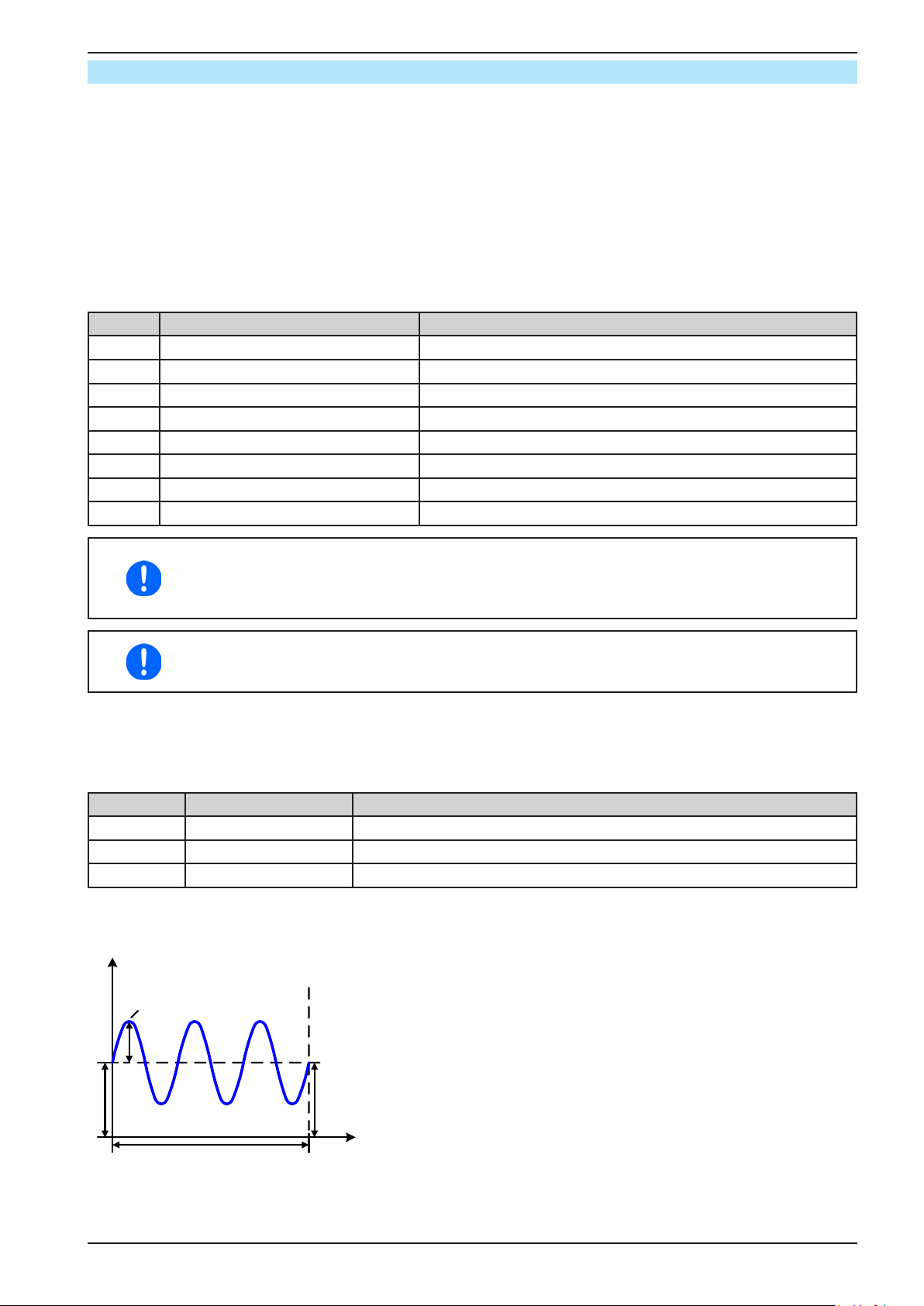
PSI 9000 2U Series
3.10.10 Arbitrary function
The arbitrary (freely denable) function offers the user further scope. Up to 100 sequence points are available for
use for current I and voltage U, all of which have the same parameters but which can be differently congured
so that a complex function process can be built up. From the 100 sequence points a block can be freely dened
to run from sequence point x to sequence point y. This block can then be repeated 1...999 times or endlessly. A
sequence point block is only applied on either current or voltage, thus a mix of assignment to current I or voltage
U is not possible.
The arbitrary function can merge a linear progression (DC part) with a sine wave (AC part), whose amplitude and
frequency are shaped between start and end values. If the start frequency (fs) and end frequency (fe) are both
0 Hz, the AC parameters have no impact and only the DC parameters are effective. Each sequence point is al-
located a time in which the AC/DC curve part will be generated from start to nish.
The following parameters can be congured for each sequence point:
Value Range Description
Is(AC) 0...50% Nominal value of I Start amplitude of the sine wave part
Ie(AC) 0...50% Nominal value of I End amplitude of the sine wave part
fs(1/T) 0 Hz...10000 Hz Start frequency of the sine wave part
fe(1/T) 0 Hz...10000 Hz End frequency of the sine wave part
Angle 0°...359° Start angle of the sine wave part
Is(DC) Is(AC)...(Nominal value - Is(AC)) of I Start value of the DC part
Ie(DC) Ie(AC)...(Nominal value - Ie(AC)) of I End value of the DC part
Seq.time 0.1 ms...36000 s Time
The sequence time (seq. time) and the start and end frequency are related. The minimum value
for Δf/s is 9.3. Thus, for example, a setting of fs = 1 Hz, fe = 11 Hz and Seq.time = 5 s would
not be accepted as Δf/s is only 2. A seq. time of 1 s would be accepted, or, if the time remains
at 5 s, then fe = 51 Hz must be set.
The amplitude change between start and end is related to the sequence time. An arbitrarily
small change over an extended time is not possible. See section „3.10.2.5. Minimum slope /
maximum ramp time“ for more information.
After the settings for the selected sequence point are accepted with SAVE, further points can be congured. If the
button NEXT is touched a second settings screen appears in which global settings for all 100 sequence points
are displayed.
The following parameters can be set for the total run of an arbitrary function:
Value Range Description
Start seq. 1...End seq. First sequence point in the sequence block
End seq. Start seq. ... 100 Last sequence point in the sequence block
Seq. Cycles ∞ or 1...999 Number of cycles of the sequence block.
Schematic diagram: Applications and results:
A
Example 1
Focussing 1 cycle of 1 sequence point from 100:
Start (AC)
DC values for start and end are the same, also the AC amplitude.
With a frequency >0 a sine wave progression of the set value is
generated with a dened amplitude, frequency and Y-shift (offset,
DC value at start and end)
The number of sine waves per cycle depend on the sequence time
and the frequency. If the sequence time were 1 s and the frequency
Start (DC)
Seq.time
End (DC)
1 Hz, there would be exactly 1 sine wave. If the time were 0.5 s at
the same frequency, there would only be a half sine wave.
t
EPS Stromversorgung GmbH
Alter Postweg 101 • 86159 Augsburg
Germany
Fon: +49 821 / 570451-0
Fax: +49 821 / 570451-25
www.eps-germany.de
Page 70
Page 71
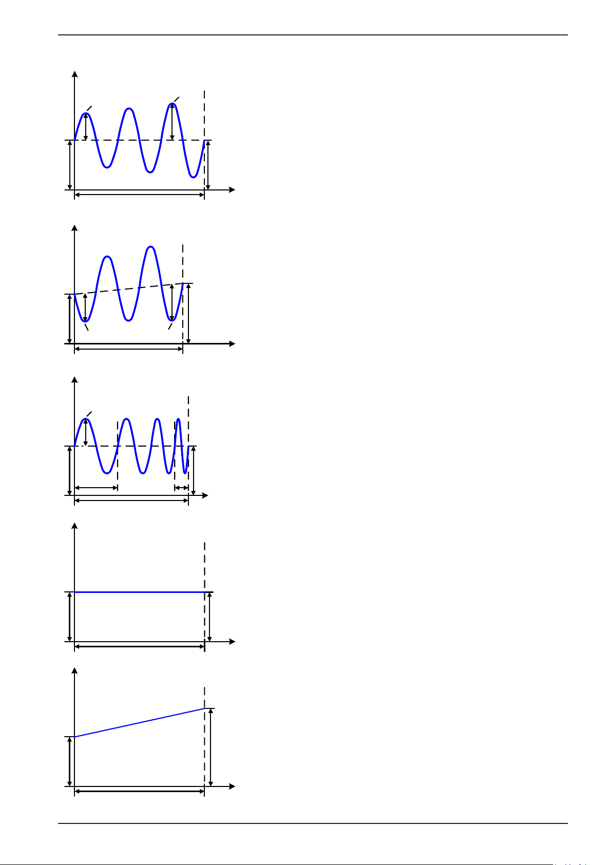
Schematic diagram: Applications and results:
Seq.time
Seq.time
A
C)
A
Start (AC)
End (
Example 2
Focussing 1 cycle of 1 sequence point from 100:
The DC values at start and end are the same but the AC (amplitude)
not. The end value is higher than the start so that the amplitude
increases with each new half sine wave continuously through the sequence. This, of course, only if the sequence point time and frequency
allow for multiple waves to be created. e.g. for f=1 Hz and Seq. time
= 3 s, three complete waves would be generated (for angle = 0°) and
Start (DC)
Seq.time
End (DC)
reciprocally the same for f=3 s and Seq. time=1 s.
t
PSI 9000 2U Series
A
Start (DC)
Start (AC) End (AC)
Seq.time
A
Start (AC)
f (start)
Start (DC)
Seq.time
A
f (end)
Example 3
Focussing 1 cycle of 1 sequence point from 100:
The DC values at start and end are unequal, as are also the AC values. In both cases the end value is higher than the start so that the
offset increases from start to end (DC) and the amplitude also with
each new half sine wave.
Additionally the rst sine wave starts with a negative half wave be-
End (DC)
cause the angle is set at 180°. The start angle can be shifted at will
in 1° steps between 0° and 359°.
t
Example 4
Focussing 1 cycle of 1 sequence point from 100:
Similar to example 1 but with another end frequency. Here this is
shown as higher than the start frequency. This impacts the period
of the sine waves such that each new wave will be shorter over the
total span of the sequence time.
End (DC)
t
Example 5
Focussing 1 cycle of 1 sequence point from 100:
Similar to example 1 but with a start and end frequency of 0 Hz.
Without a frequency no sine wave part (AC) will be created and only
the DC settings will be effective. A ramp with a horizontal progression is generated.
Start (DC)
A
Start (DC)
EPS Stromversorgung GmbH
Alter Postweg 101 • 86159 Augsburg
Germany
End (DC)
t
Example 6
Focussing 1 cycle of 1 sequence point from 100:
Similar to example 1 but with a start and end frequency of 0 Hz. Without a frequency no sine wave part (AC) will be created and only the
DC settings will be effective. Here start and end values are unequal
and a steadily increasing ramp is generated.
End (DC)
t
Fon: +49 821 / 570451-0
Fax: +49 821 / 570451-25
www.eps-germany.de
Page 71
Page 72
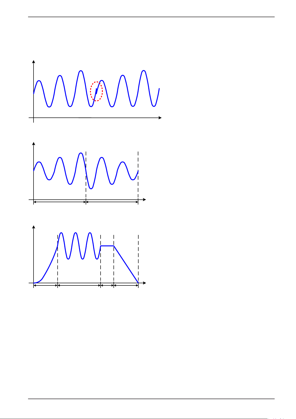
PSI 9000 2U Series
By linking together a number of differently congured sequence points, complex progressions can be created.
Smart conguration of the arbitrary generator can be used to match triangular, sine, rectangular or trapezoidal wave
functions and thus, e.g. a curve of rectangular waves with differing amplitudes or duty cycles could be produced.
Schematic diagram: Applications and results:
A
Example 7
Focussing 1 cycle of 2 sequence points from
100:
A sequence point congured as in example
3 is run. As the settings demand that the end
offset (DC) is higher than the start, the second
sequence point run will revert to the same
start level as the rst, regardless of the values
achieved at the end of the rst run. This can
t
produce a discontinuity in the total progression
(marked in red) which may only be compensated with careful choice of settings.
A
Point 1 Point 2
A
Point 1 Point 2 Pt. 3 Point 4
Example 8
Focussing 1 cycle of 2 sequence points from
100:
Two sequence points run consecutively. The
rst generates a sine wave with increasing
amplitude, the second with a decreasing amplitude. Together they produce a progression as
shown left. In order to ensure that the maximum
wave in the middle occurs only once, the rst
t
one must end with a positive half wave and the
second one with a negative half wave as shown
in the diagram..
Example 9
Focussing 1 cycle of 4 sequence point from 100:
Sequence point 1: 1/4th sine wave (angle =
270°)
Sequence point 2: 3 Sine waves (ratio of frequency to sequence time 1:3)
Sequence point 3: Horizontal ramp (f = 0)
Sequence point 4: Falling ramp (f = 0)
t
EPS Stromversorgung GmbH
Alter Postweg 101 • 86159 Augsburg
Germany
Fon: +49 821 / 570451-0
Fax: +49 821 / 570451-25
www.eps-germany.de
Page 72
Page 73
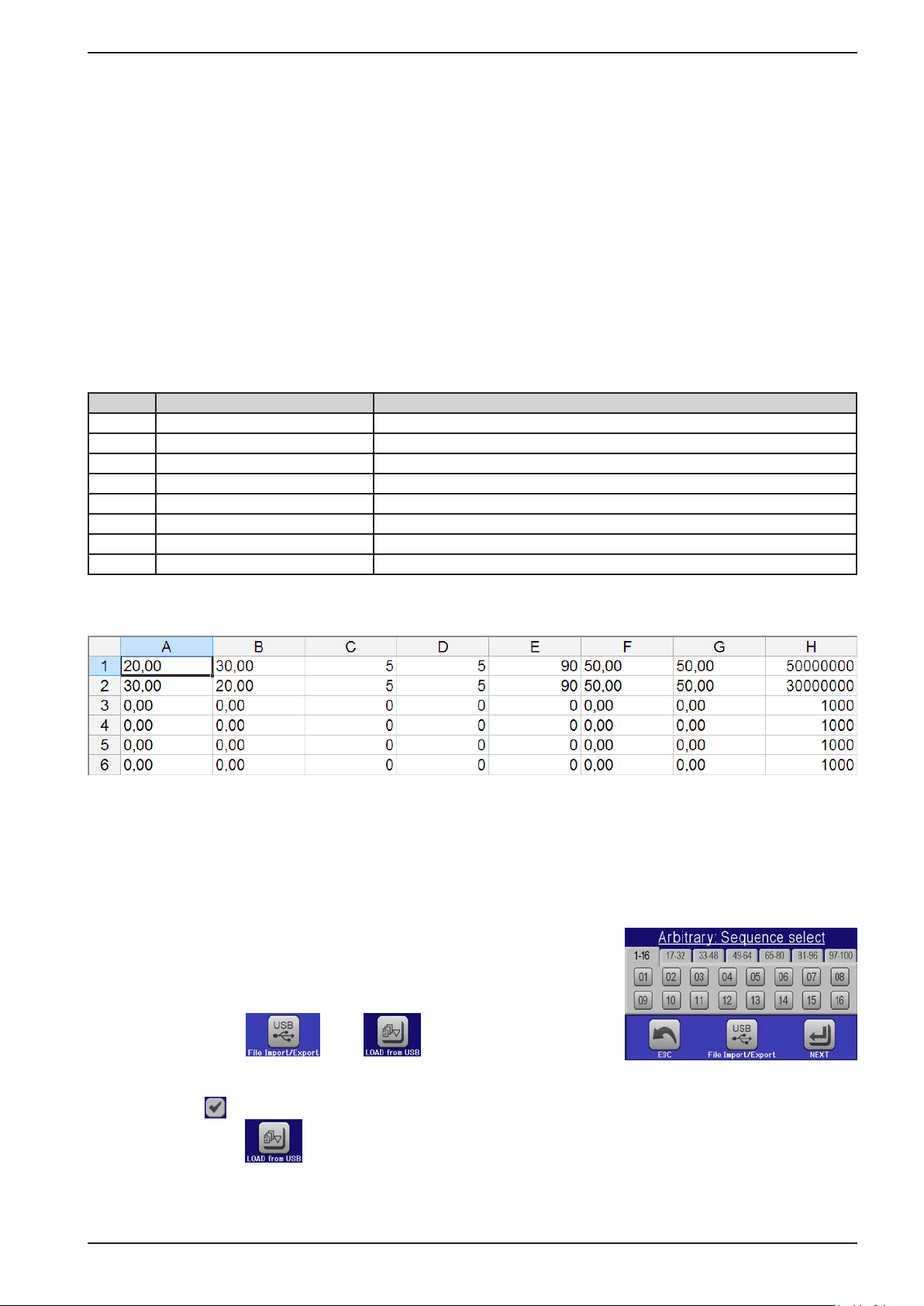
PSI 9000 2U Series
3.10.10.1 Loading and saving the arbitrary function
The 100 sequence points of the arbitrary function, which can be manually congured with the control panel of the
device and which are applicable either to voltage (U) or current (I), can be saved to or loaded from a common
USB stick via the front side USB port. Generally, all 100 points are saved or loaded using a text le of type CSV
(semicolon separator), which represents a table of values.
In order to load a sequence point table for the arbitrary generator, following requirements have to be met:
• The table must contain exactly 100 rows with 8 subsequent columns and must not have gaps
• The column separator (semicolon, comma) must be as selected by MENU parameter “USB le separator format”;
it also denes the decimal separator (dot, comma)
• The les must be stored inside a folder called HMI_FILES which has to be in the root of the USB drive
• The le name must always start with WAVE_U or WAVE_I (not case-sensitive)
• All values in every row and column have to be within the specied range (see below)
• The columns in the table have to be in a dened order which must not be changed
Following value ranges are given for use in the table, related to the manual conguration of the arbitrary generator
(column headers like in Excel):
Column Parameter Range
A AC start amplitude 0...50% U or I
B AC end amplitude 0...50% U or I
C Start frequency 0...1000 Hz
D End frequency 0...1000 Hz
E AC start angle 0...359°
F DC start offset 0...(Nominal value of U or I) - AC start amplitude
G DC end offset 0...(Nominal value of U or I) - AC end amplitude
H Sequence point time in μs 100...36.000.000.000 (36 billion μs)
For details about the parameter and the arbitrary function refer to „3.10.10. Arbitrary function“.
Example CSV:
The example shows that only the rst two sequence points are congured, while all others are set to default values. The table could be loaded as WAVE_U or WAVE_I when using, for example, the model PSI 9080-120 2U,
because the values would t both, voltage and current. The le naming, however, is unique. A lter prevents you
from loading a WAVE_I le after you have selected “Arbitrary --> U” in the function generator menu. The le would
not be listed as selectable at all.
► How to load a sequence point table from an USB stick:
1. Do not plug the USB drive yet or remove it.
2. Access the function selection menu of the function generator with
MENU -> Function Generator -> Arbitrary -> U/I, to see the main screen
of sequence point selector, as depicted to the right.
3. Tap touch area , then and follow the instructions
on screen. If at least one valid les has been recognized (for le and
path naming see above), the device will show a list of les to select
from with .
4. Tap touch area in the bottom right corner. The selected le is then checked and loaded, if valid.
In case it is not valid, the device will show an error message. Then the le must be corrected and the
steps repeated.
EPS Stromversorgung GmbH
Alter Postweg 101 • 86159 Augsburg
Germany
Fon: +49 821 / 570451-0
Fax: +49 821 / 570451-25
www.eps-germany.de
Page 73
Page 74
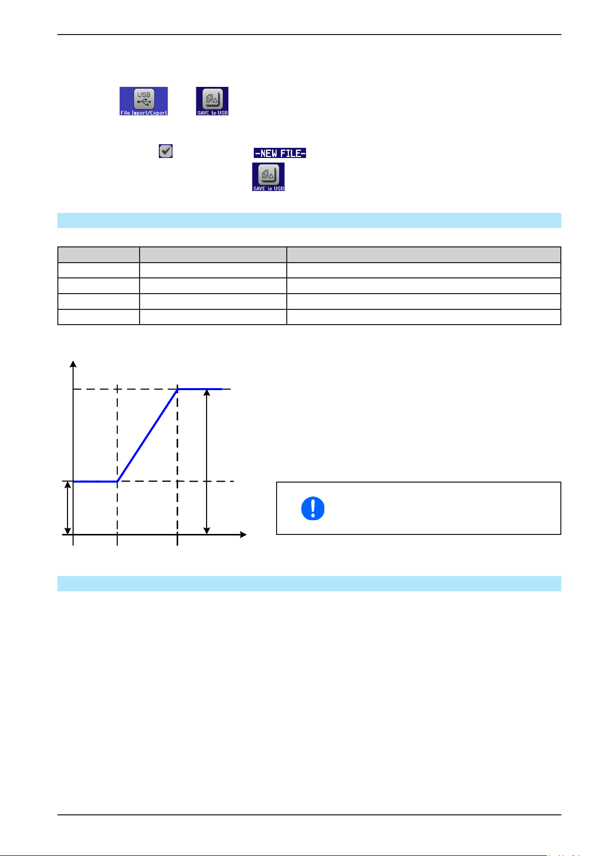
PSI 9000 2U Series
A.start
► How to save a sequence point table to an USB stick:
1. Do not plug the USB stick yet or remove it.
2. Access the function selection menu of the function generator via MENU -> Function Generator -> Arbitrary
3. Tap on , then . The device will request you to plug the USB stick now.
4. After plugging it, the device will try to access the stick and nd the folder HMI_FILES and read the content.
If there are already WAVE_U or WAVE_I les present, they will be listed and you can either select one for
overwriting with , otherwise select for a new le.
5. Finally save the sequence table with .
3.10.11 Ramp Function
The following parameters can be congured for a ramp function.
Value Range Description
Ustart / Istart 0...Nominal value of U, I Start value (U,I)
Uend / Iend 0...Nominal value of U, I End value (U, I)
t1 0,1 ms...36000 s Time before ramp-up or ramp-down of the signal.
t2 0.1 ms...36000 s Ramp-up or ramp-down time
Schematic diagram: Application and result:
A
This function generates a rising or falling ramp between start
and end values over the time t2. Time t1 creates a delay before
the ramp starts.
The function runs once and stops at the end value.
Important to consider are the static values of U and I which dene
the start levels at the beginning of the ramp. It is recommended
that these values are set equal to those in A.start, unless the load
at the DC output should not be provided with voltage before the
start of the ramp. In that case the static values should be set to
A.End
zero.
10h after reaching the ramp end, the function
will stop automatically (i.e. I = 0 A resp. U =
0 V), unless it has been stopped manually
before.
t1 t2
t
3.10.12 UI and IU table functions (XY table)
The UI and IU functions offer the user the possibility to set a DC output current dependant on the DC output voltage, or a DC output voltage dependant on the DC output current. The function is table driven with exactly 4096
values, which are distributed over the whole measured range of actual output voltage or output current in the range
of 0...125% Unom or Inom. The table can either be uploaded from an USB stick through the front side USB port
of the device or via remote control (ModBus protocol or SCPI). The functions are:
UI function: U = f(I)
IU function: I = f(U)
In the UI function, the equipment measuring circuit determines the level from 0 to maximum of the output current.
For each of the 4096 possible values for output current a voltage value is maintained by the user in the UI table
which can be any value between 0 and nominal value. The values uploaded from an USB stick will always be
interpreted as voltage values even if the user calculated them as current values and incorrectly loaded them as
an UI table. The UI function suits very good for the simulation of fuel cell characteristics.
EPS Stromversorgung GmbH
Alter Postweg 101 • 86159 Augsburg
Germany
Fon: +49 821 / 570451-0
Fax: +49 821 / 570451-25
www.eps-germany.de
Page 74
Page 75
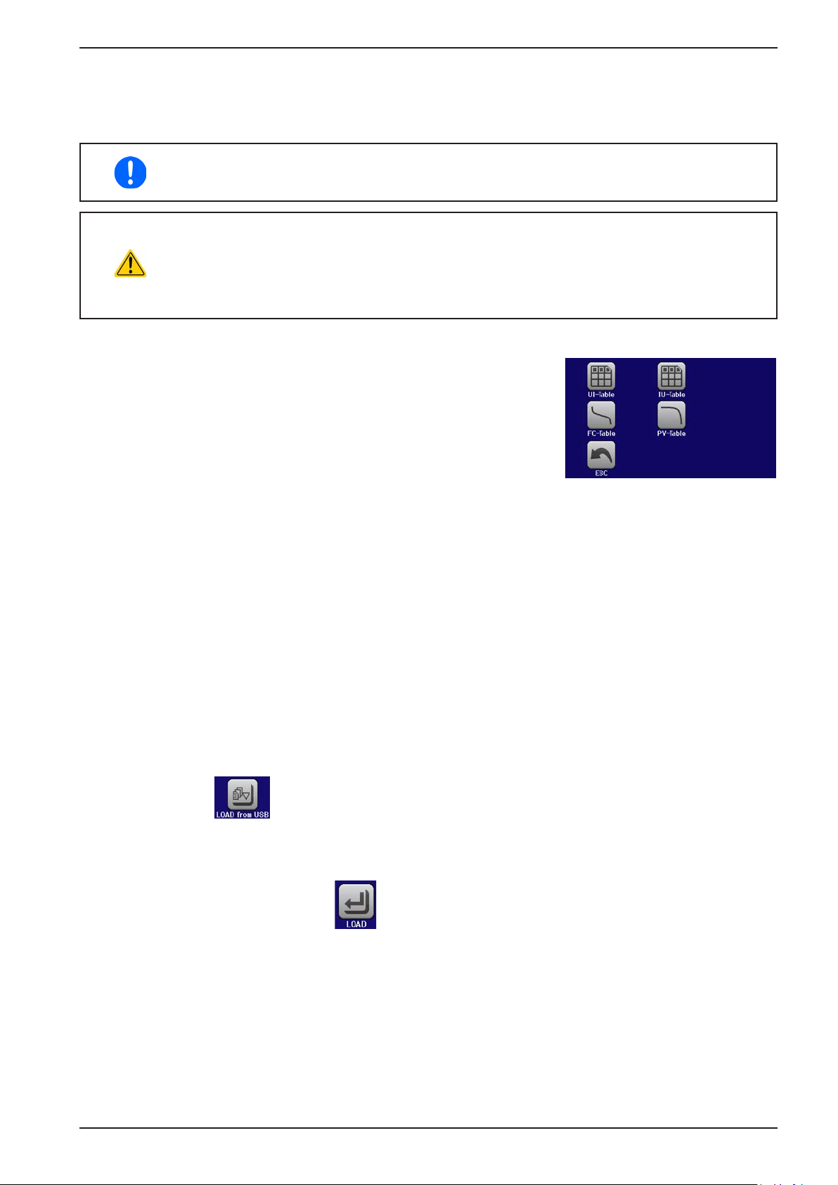
PSI 9000 2U Series
In the IU function the assignment of the values is the other way round, the behaviour, however, the same.
Thus the behaviour of the load or the current and power consumption can be controlled with dependance on output
voltage and step changes can be created.
The IU function suit very good for the simulation of solar panels in photovoltaics related tests.
Uploading of a table from an USB stick must use text les in CSV format (*.csv). Plausibility is
checked on loading (values not too high, number of values correct) and possible errors reported
in which case the table will not be loaded.
The 4096 values in the table are only checked for size and count. If all the values were to be
graphically plotted, a curve would be created which could include signicant step changes in
current or voltage. That could lead to complications for connected loads if, for example, the
internal current measurement in the power supply swings slightly so that the voltage jumps
backwards and forwards between two values in the table, which, in the worst case, could be 0
V and the maximum voltage.
3.10.12.1 Loading UI and IU tables from USB drive
The so-called UI or IU value tables can be loaded from a le via a standard
USB stick that is formatted as FAT32. In order to load the le, it has to meet
following specications:
• The le name always begins with IU or UI (not case-sensitive), depending
on which of the two function you load the table for
• The le must be a text le of type Excel CSV (semicolon as separator)
and must only contain one column with exactly 4096 values without gaps
• Values with decimal places must use the commas (“,”) as decimal separator
• No value may exceed the nominal value of the device. For example, if you have an 80 V model and you are
going to load a table with values for voltage, none of the 4096 values may be higher than 80 V (the adjustment
limits from the device’s front panel do not apply here)
• The le(s) has/have to be put inside a folder named HMI_FILES in the root of the USB stick
If these specications are not met, the device won’t accept the le and put out an error message in the display.
Files with names beginning different to UI or IU are not recognized for this purpose. The USB drive may contain
multiple UI/IU les with different names and list them for the selection of one.
► How to load an UI or IU table from an USB drive:
1. Do not plug the USB drive yet or pull it out if already plugged.
2. Open the function selection menu of the function manager with MENU -> Function Generator -> XY Table
3. In the next scree select the desired function with either „UI Table“ or „IU Table“.
4. Congure the global parameters for U, I and P, if necessary.
5. Tap touch area and plug the USB drive when requested, in order to select one out of X compatible
les from the drive. In case the le is not accepted, the device will report an error in the display and also tell
what’s wrong with the le.
6. Once the le is accepted, you will be requested to remove the USB drive.
7. Submit and load the function with to start and control it as with other function (also see „3.10.4.1.
Function selection and control“).
EPS Stromversorgung GmbH
Alter Postweg 101 • 86159 Augsburg
Germany
Fon: +49 821 / 570451-0
Fax: +49 821 / 570451-25
www.eps-germany.de
Page 75
Page 76
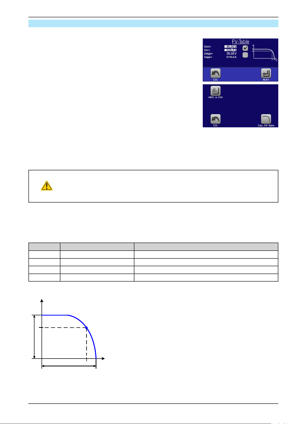
3.10.13 PV table function (photovoltaics)
3.10.13.1 Preface
This function uses the standard XY generator to make the power supply simulate
solar panels or solar cells with certain characteristics. The device calculates
an IU table from four typical values.
While the function is running, the user can adjust a parameter “Irradiance”
between 0% (darkness) and 100% (bright light) in 1% steps to simulate different light situations.
The most important characteristics of a solar cell are:
• the short-circuit current (ISC), which is proportional to the irradiance
• the open circuit voltage (UOC), which almost reaches its maximum value
even in low light situations
• the maximum power point (MPP), at which the solar panel can provide the
maximum output power
The voltage of the MPP (here: U
of the MPP (here: I
) lies typically 5% below ISC. In case there are no denite
MPP
values for the simulated solar cell available, Impp and Umpp can be set to this
rule of thumb. The device limits the I
applies for U
and UOC.
MPP
) lies typically 20% below UOC, the current
MPP
value to ISC as upper limit, the same
MPP
PSI 9000 2U Series
3.10.13.2 Safety notices
Due to high capacities on the DC outputs of the power supplies of this series, not every avail-
able solar inverter can be operated without problems. Check the technical specications of
the solar inverter and probably contact the manufacturer for an evaluation. In case option HS
is installed in the device (see „1.9.5. Options“), the result of operating critical inverters can be
optimised.
3.10.13.3 Usage
In the PV table function, which is based upon the XY generator with IU characteristics, the MPP is dened by the
two adjustable parameters Umpp and Impp (also see diagram below). These parameters are usually stated in data
sheets of solar panels and have to be entered here.
The following parameters can be set for the PV table function:
Value Range Description
Uoc Umpp...Nominal device voltage Open circuit voltage at no load
Isc Impp...Nominal device current Short-circuit current at max. load and low voltage
Umpp 0 V...Uoc DC output voltage at the MPP
Impp 0 A...Isc DC output current at the MPP
Schematic diagram: Application and result:
I
Adjust all four parameters on screen to the desired values. Whether the
calculated IU and P curves, which result from those values, make sense or
not can be veried with a tool like Excel by generating a diagram.
While the simulation is running, the user can see from the actual values
MPP
Impp
Isc
(voltage, current, power) of the DC output, where the operating point of the
power supply resp. of the simulated solar panel is. The adjustable value Ir-
radiance (0%...100% in 1% steps, see screenshot below) helps to simulate
different light situations from darkness (no power output) to the minimal
amount of light that is required to make the panel provide full power.
Umpp
Uoc
EPS Stromversorgung GmbH
Alter Postweg 101 • 86159 Augsburg
Germany
U
Fon: +49 821 / 570451-0
Fax: +49 821 / 570451-25
www.eps-germany.de
Page 76
Page 77
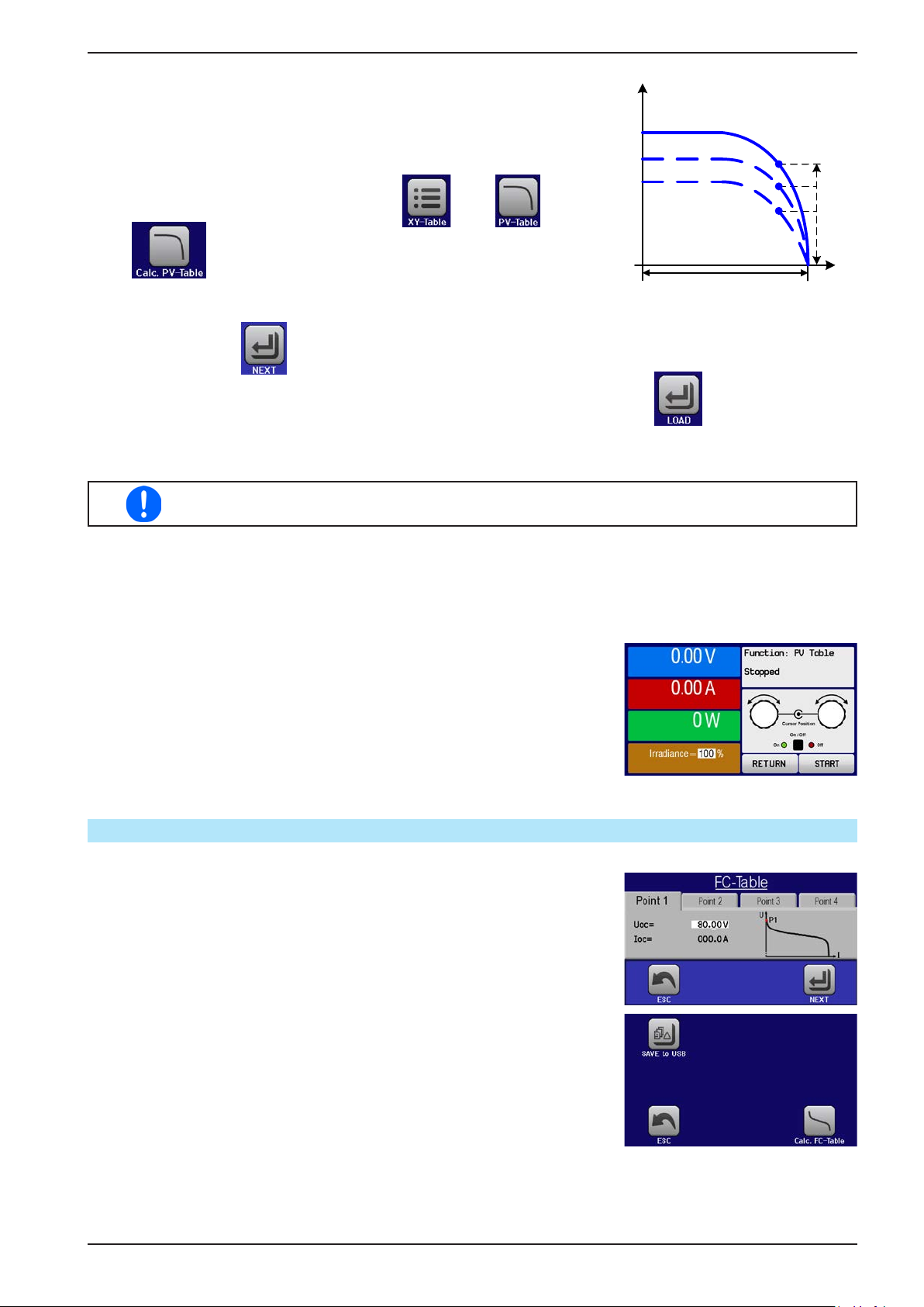
PSI 9000 2U Series
Varying this parameter shifts the MPP and the PV curve along the Y axis. Also
I
see diagram to the right. The value Irradiance is here used as a factor for the
current Impp. The curve itself is not permanently re-calculated.
► How to congure the PV table
1. In the function generator menu tap on , then and then
.
2. Adjust the four parameters as required for the simulation.
MPP
Irradiance 0..100%
U
Uoc
3. Do not forget to adjust the global limits for voltage and power in the next screen which you can access
with touch area . The voltage (U) setting should be at least as high as Uoc, or higher.
4. After setting the values for the required signal generation, tap on touch area .
While loading, the IU function is calculated and sent to the internal XY generator. After this, the function is ready
to run.
The function can be saved to USB stick as table, as well as read via any of the digital interfaces.
In remote control, the function can not be loaded or controlled.
From the screen where the XY function generator is controlled manually (start/stop), you can go back to the rst
screen of PV table function and use the formerly locked touch area to save the table to USB drive. In order to
do so, follow the on-screen instructions. The table can be used to analyse the values or to visualise it in Excel or
similar tools.
► How to work with the PV table function
1. With an appropriate load connected, for example a solar inverter, start
the function as described in 3.10.4.1.
2. Adjust value Irradiance with the left rotary knob between 100% (default)
and 0%, in order to simulate different light situations. The actual values
on the display indicate the working point and can show whether the
simulation has arrived at the MPP or not.
3. Stop the function run anytime as described in 3.10.4.1.
3.10.14 FC table function (fuel cell)
3.10.14.1 Preface
The FC table function is used to simulate the characteristics of voltage and
current of a fuel cell. This is achieved by setting up some parameters which
dene points on a typical fuel cell curve, which is then calculated as UI table
and passed to the internal function generator.
The user has to adjust value for four support points. The device will request
to enter them step by step, indicating the actual point on screen with small
graphics. When nished, these points will be used to calculate the curve.
Generally, following rules apply when setting up those values:
• U
• I
• Values of zero are not accepted
It means, the voltage has to decrease from point 1 to point 4, while the current has to increase. In case the rules are not followed, the device will reject
the values with an error and reset them to 0.
Point1
Point4
> U
> I
Point3
Point2
> I
> U
Point2
Point3
> I
> U
Point1
Point4
EPS Stromversorgung GmbH
Alter Postweg 101 • 86159 Augsburg
Germany
Fon: +49 821 / 570451-0
Fax: +49 821 / 570451-25
www.eps-germany.de
Page 77
Page 78
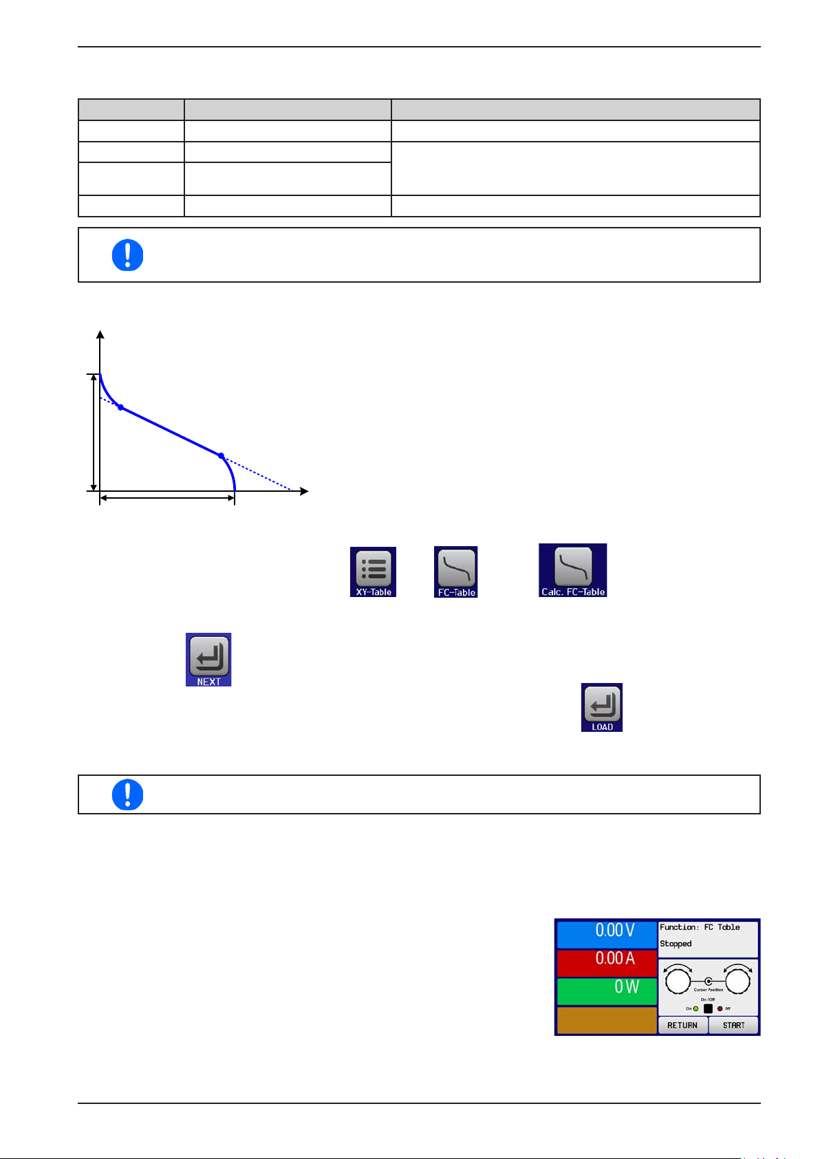
3.10.14.2 Usage
The following parameters can be set for the FC table function:
Value Range Description
Point 1: Uoc 0 V...U
Point 2+3: U 0 V...U
Point 2+3: I 0 A...I
Point 4: Isc 0 A...I
Nom
Nom
Nom
Nom
Open circuit voltage at no load
Voltage and current dene the position of these two points
in the U-I coordinate system, which represent two supporting points on the curve to be calculated
DC output current at the MPP
All these parameters all freely adjustable and thus an unrealistic curve could result. In some
situations, the device would show a “Calculation error” after you tapped LOAD and loading of
the function will be aborted. In this situation, check your settings, probably revise and try again.
Schematic diagram: Application and result:
U
After setting up the four supporting points P1 thru P4, whereas P1 is at
position Uoc and 0 A and P4 is at position Isc and 0 V, the device will
calculate the function as UI table and load it to the XY generator.
Depending on the load current, which can be between 0 A and Isc, the
P2
Uoc
P3
device will set a variable output voltage, whose progress between 0 V
and Uoc should result in a curve similar to the one depicted to the left.
The slope between P2 and P3 is depending on the values adjusted for
P2 and P3 and can be freely modied as long as P3’s voltage is lower
than the one of P2 and P3’s current is higher than the one of P2.
PSI 9000 2U Series
Isc
I
► How to congure the FC table
1. In the function generator menu tap on , then and then .
2. Adjust the parameters of the four supporting points, as required for the simulation.
3. Do not forget to adjust the global limits for current and power in the screen which you can access with
touch area .
4. After setting the values for the required signal generation, tap on touch area .
After the function has been loaded to the internal XY generator, the simulation is ready to start.
The function can be saved to USB stick as table, as well as read via any of the digital interfaces.
In remote control, the function can not be loaded or controlled.
From the screen where the XY function generator is controlled manually (start/stop), you can go back to the rst
screen of the FC table function and use the formerly locked touch area to save the table to USB drive. In order to
do so, follow the on-screen instructions. The table can be used to analyse the values or to visualise it in Excel or
similar tools.
► How to work with the FC table function
1. With an appropriate load connected, for example a DC-DC converter,
start the function as described in 3.10.4.1.
2. The output voltage will be set depending on the load current, which is
dened by the connected load, and will decrease with increasing current. Without any load, the voltage will rise to the adjusted Uoc value.
3. Stop the function run anytime as described in 3.10.4.1.
EPS Stromversorgung GmbH
Alter Postweg 101 • 86159 Augsburg
Germany
Fon: +49 821 / 570451-0
Fax: +49 821 / 570451-25
www.eps-germany.de
Page 78
Page 79

PSI 9000 2U Series
3.10.15 Remote control of the function generator
The function generator can be remotely controlled but conguration and control of the functions with individual
commands is different from manual operation. The external documentation “Programming Guide ModBus & SCPI”
explains the approach. In general the following apply:
• The function generator is not controllable via the analog interface
• The function generator is unavailable if R mode (resistance) is activated
• Some functions are based on the arbitrary generator, some on the XY generator. Therefore, both generators
have to be controlled and congured separately
EPS Stromversorgung GmbH
Alter Postweg 101 • 86159 Augsburg
Germany
Fon: +49 821 / 570451-0
Fax: +49 821 / 570451-25
www.eps-germany.de
Page 79
Page 80
PSI 9000 2U Series
3.11 Other applications
3.11.1 Parallel operation in master-slave mode (MS)
Multiple devices of same kind and model can be connected in parallel in order to create a system with higher total
current and hence higher power. For master-slave operation, the units are usually connected with their DC outputs,
their Share bus and their digital master-slave bus.
The master-slave bus is a digital bus which makes the system work as one big unit regarding adjusted values,
actual values and status.
The Share bus is intended to balance the units dynamically in their output voltage, especially if the master unit
runs a function like sine wave etc. In order for this bus to work correctly, at least the DC minus poles of all units
have to be connected, because DC minus is the reference for the Share bus.
3.11.1.1 Restrictions
Compared to normal operation of a single device, master-slave operation has some restrictions:
• The MS system reacts differently to alarm situations (see below in 3.11.1.6)
• Using the Share bus makes the system reacts as dynamically as possible, but it is still not as dynamic as single
unit operation
3.11.1.2 Wiring the DC outputs
The DC output of every unit in the parallel operation is simply connected to the next unit using cables with cross
section according to the maximum current and with short as possible length.
3.11.1.3 Wiring the Share bus
The Share bus is wired from unit to unit with an ideally twisted pair of cables with non-critical cross section. We
recommend to use 0.5 mm² to 1.0 mm².
• The Share bus is poled. Take care for correct polarity of the wiring!
• In order for the Share bus to work correctly it requires at least to connect all DC minus
outputs of the devices
A max. of 16 units can be connected via Share bus.
3.11.1.4 Wiring and set-up of the master-slave bus
The master-slave connectors are built-in and can be connected via network cables (≥CAT3, patch cable). After
this, MS can be congured manually (recommended) or by remote control. The following applies:
• A maximum of 16 units can be connected via the bus: 1 master and up to 15 slaves
• Only devices of same kind, i.e. power supply to power supply, and of the same model, such as PSI 9080-60 2U
to PSI 9080-60 2U
• Units at the end of the bus must be terminated (see below)
The master-slave bus must not be wired using crossover cables!
Later operation of the MS system implies:
• The master unit displays, or makes available to be read by the remote controller, the sum of the actual values
of all the units
• The ranges for setting the values, adjustment limits, protections (OVP etc.) and user events (UVD etc.) of the
master are adapted to the total number of units. Thus, if e.g. 5 units, each with a power of 1.5 kW, are connected
together to a 7.5 kW system, then the master can be set in the range 0...7.5 kW.
• Slaves cannot be controlled manually as long as they’re in remote control by the master
• In case the function generator of the master unit is going to be used, the Share bus must be connected as well
EPS Stromversorgung GmbH
Alter Postweg 101 • 86159 Augsburg
Germany
Fon: +49 821 / 570451-0
Fax: +49 821 / 570451-25
www.eps-germany.de
Page 80
Page 81
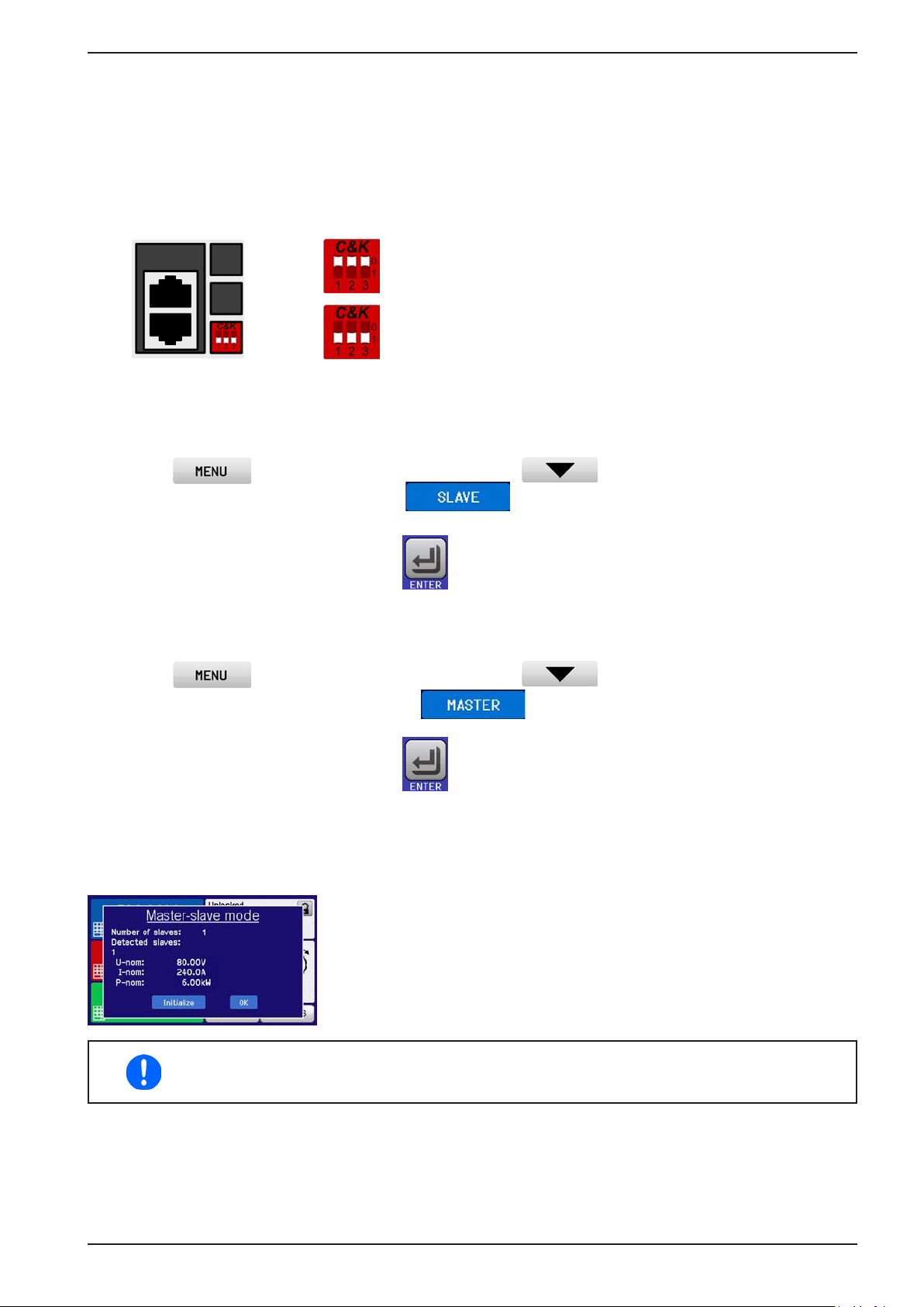
PSI 9000 2U Series
► How to connect the master-slave bus:
1. Switch off all units that are to be connected and connect them together with network cables (CAT3 or bet-
ter, not included). It doesn’t matter which of the two master-slave connection sockets (RJ45, backside) is
connected to the next unit.
2. Depending on the desired conguration the units can then be connected at the DC side.
3. The two units at the beginning and end of the chain should be terminated, if long connection cables are
used. This is achieved using a 3-pole DIP switch which is positioned on the back side of the unit next to the
MS connectors.
Position: not terminated (standard)
►
Position: terminated
Now the master-slave system must be configured on each unit. It is recommended to configure first all the slave
units and then the master unit.
► Step 1: Configuring all slave units
1. Enter then GENERAL SETTINGS and press until reaching PAGE 9.
2. Activate the MS mode with touch area . A warning requester will appear which has to be
acknowledged with OK, otherwise the change will be reverted.
3. Accept the settings with the touch area and return to the main page.
The slave is then congured for master-slave. Repeat the procedure for all other slave units.
► Step 2: Configuring the master unit
1. Enter then GENERAL SETTINGS and press until reaching PAGE 9.
2. Specify the unit as master with tough area . A warning requester will appear which has to be
acknowledged with OK, otherwise the change will be reverted.
3. Accept the settings with the touch area and return to the main page.
► Step 3: Initialising the master
The master unit and the whole master-slave system must now be initialised, which is done automatically after the
master unit has been activated for MS. In the main page, after quitting the setting menus, a pop-up will appear:
Tapping INITIALIZE can be used to repeat the search again, in case the detected number of slaves is less than expected. This can be necessary if not
all units are set as SLAVE or the cabling/termination is still not OK. The result
window shows the number of slaves and the total current and power of the
MS system.
In case there are no slaves found or not present, i.e. not powered, the master
will still initialise the MS system with only itself.
The initialising process of the master and the master-slave system will, as long as MS mode is
still activated, be repeated each time the units are powered. The initialisation can be repeated
anytime via the MENU in GENERAL SETTINGS, PAGE: 10.
EPS Stromversorgung GmbH
Alter Postweg 101 • 86159 Augsburg
Germany
Fon: +49 821 / 570451-0
Fax: +49 821 / 570451-25
www.eps-germany.de
Page 81
Page 82
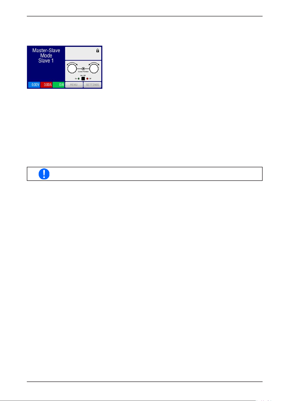
PSI 9000 2U Series
3.11.1.5 Operating the master-slave system
After successful conguration and initialisation of the master and slave units, these will show their status in the
displays. While the master merely shows “Master” in the status area, the slave(s) will continuously show like this,
as long they are in remote control by the master:
It means, aslong as a slave unit is in control by the master, it won’t display any
set or actual values, but it will show the DC output status and possible alarms.
The slaves can no longer be controlled manually or remotely, neither via the analog nor via digital interfaces. They
can, if needed, be monitored by reading actual values and status.
The display on the master unit changes after initialisation and all set values are reset. The master now displays
the set and actual values of the total system. Depending on the number of units, the total current and power will
multiply. The following applies:
• The master can be treated as a standalone unit
• The master shares the set values across the slaves and controls them
• The master is remotely controllable via the analog or digital interfaces
• All settings for the set values U,I and P (monitoring, settings limits etc.) will be adapted to the new total values
• All initialised slave will reset any limits (U
(UCD, OVD etc.) to default values, so these don’t interfere the control by the master
, I
etc.), supervision thresholds (OVP, OPP etc.) and event settings
Min
Max
In order to easily restore all these settings values to what was before activating MS operation, it
is recommended to make use of the user proles (see „3.9. Loading and saving a user prole“)
• If one or more slaves report an device alarm, this will be displayed on the master and must be acknowledged
there so that the slave(s) can continue operation. Since an alarm causes the DC output to be switched off and
it can only reinstate automatically after PF or OT alarms, it can be required to switch it on again by the operator
or by a remote control software.
• Loss of connection to any slave will result in shutdown of all DC outputs, as a safety measure, and the master
will report this situation in the display with a pop-up “Master-slave safety mode”. Then the MS system has to be
re-initialised, either with or without re-establishing connection to the disconnected unit(s) before
• All units, even the slaves, can be externally shut down on the DC outputs using the pin REM-SB of the analog
interface. This can be used as some kind of emergency off, where usually a contact (maker or breaker) is wired
to this pin on all unit in parallel.
3.11.1.6 Alarms and other problem situations
Master-slave operation, due to the connection of multiple units and their interaction, can cause additional problem
situations which do not occur when operating individual units. For such occurrences the following regulations have
been dened:
• If the DC part of one or more slave units is switched off due to defect, overheating etc., the whole MS system
shuts down the power output and human interaction is required
• If one or more slave units are cut from AC supply (power switch, blackout, supply undervoltage) and come back
later, they’re not automatically initialised and included again in the MS system. Then the init has to be repeated.
• If the DC output of the master unit is switched off due to a defect or overheating, then the total master-slave
system can provide no output power and the DC outputs of all slaves are automatically switched off, too
• If the master unit is cut from AC supply (power switch, blackout) and comes back later, the unit will automati-
cally initialise the MS system again, nding and integrating all active slaves. In this case, MS can be restored
automatically.
• If accidently multiple or no units are dened as master the master-slave system cannot be initialised
EPS Stromversorgung GmbH
Alter Postweg 101 • 86159 Augsburg
Germany
Fon: +49 821 / 570451-0
Fax: +49 821 / 570451-25
www.eps-germany.de
Page 82
Page 83
PSI 9000 2U Series
In situations where one or multiple units generate a device alarm like OV, PF or OT following applies:
• Any alarm of a slave is indicated on the slave’s display and on the master’s display
• If multiple alarms happen simultaneously, the master only indicates the most recent one. In this case, the par-
ticular alarms can be read from the slave units displays or via digital interface during remote control or remote
supervision.
• All units in the MS system supervise their own values regarding overvoltage, overcurrent and overpower and
in case of alarm they report the alarm to the master. In situations where the current is probably not balanced
between the units, it can occur that one unit generates an OCP alarm though the global OCP limit of the MS
system was not reached. The same can occur with the OPP alarm.
3.11.1.7 Important to know
In case one or several units of a parallel system are not going to be used and remain switched
off, depending on the number of active units and the dynamics of the operation it may become
necessary to disconnect the inactive units from the Share bus, because even when not powered
the units can have a negative impact on the Share bus due to their impedance.
3.11.2 Series connection
Series connection of two or multiple devices is basically possible. But for reasons of safety and isolation, some
restrictions apply:
• Both, negative (DC-) and positive (DC+) output poles, are coupled to PE via type X capacitors,
limiting the max. allowed potential shift (see technical specs for values)
• The Share Bus must not be wired and used!
• Remote sensing must not be used!
• Series connection is only allowed with devices of the same kind and model, i.e. power supply
with power supply, like for example PS/PSI 9080-60 2U with PSI 9080-60 2U or PS 9080-60 2U
Series connection in Master-Slave mode is not supported. It means, all units have to controlled separately regarding set values and DC output status, whether it is manual control or digital remote control.
According to the limit of the potential shift that comes with series connection, units with a certain nominal output
voltage must not be connected in series at all. For example, the 750 V, because there the DC minus is only isolated
up to ±400 V DC against PE. On the opposite, two 360 V units are allowed to be connected in series.
The analog interfaces of units in series connection are allowed to be wired in parallel, because they are galvanically
isolated from the device and the DC output. The grounds (AGND, DGND) on the analog interface are also allowed
to be directly connected to PE, like it automatically happens when controlling and directly connecting it to a PC.
3.11.3 Operation as battery charger
A power supply can be used as a battery charger, but with some restrictions, because it misses a battery supervision and a physical separation from the load in form of a relay or contactor, which is featured with some real battery
chargers as a protection.
Following has to be considered:
• No false polarity protection inside! Connecting a battery with false polarity will damage the power supply severely,
even if it is not powered.
• All models of this series have an internal circuit, i.e. base load, for faster discharge of voltage when switching the
DC output off or ramping voltage down. This base load would, more or less slowly, discharge the battery while
the DC output is switched off, means while it is not charging. This would, however, not occur when the power
supply is not powered at all. It is thus recommended to leave the DC output switched on as long as the battery
is connected (equals to trickle charge) and only switch if off for connecting/disconnecting a battery.
EPS Stromversorgung GmbH
Alter Postweg 101 • 86159 Augsburg
Germany
Fon: +49 821 / 570451-0
Fax: +49 821 / 570451-25
www.eps-germany.de
Page 83
Page 84
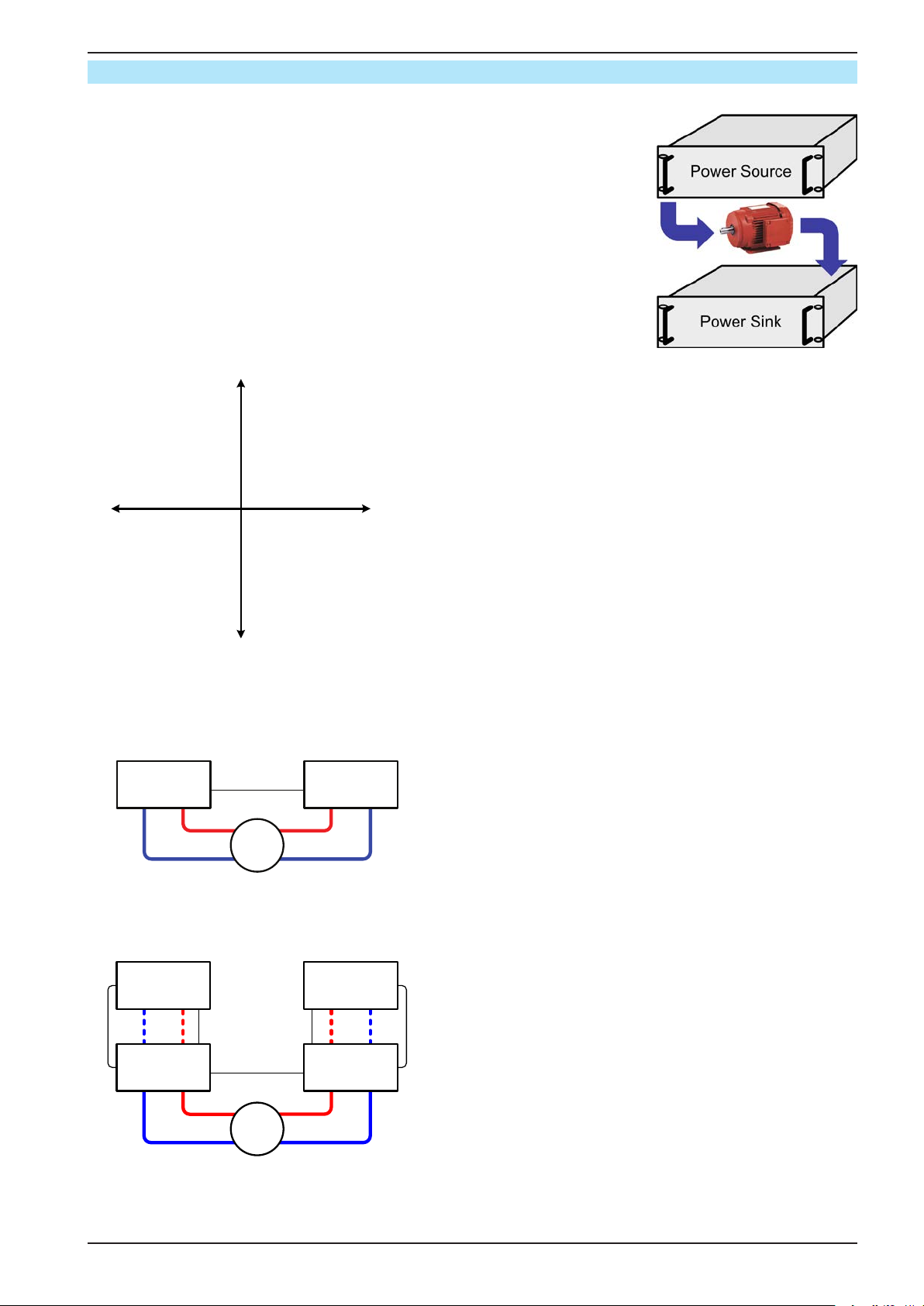
3.11.4 Two quadrant operation (2QO)
3.11.4.1 Introduction
This way of operating refers to the use of a source, in this case a power supply
of this series PSI 9000 2U, and a sink, for example a series ELR 9000 electronic
load. The source and the sink function alternately in order to test a device, such
as a battery, by deliberate charging and discharging as part of a functional or
nal test
The user can decide whether the system is operated manually or the power
supply only as the dominant unit or both devices should be controlled by PC.
We recommend to focous on the power supply, which is intended to control the
load’s behaviour regarding voltage and current via the Share Bus connection.
Two quadrant operation is only suitable for constant voltage operation (CV).
Clarication:
U+
III
I-
III
IV
U-
I+
A combination of source and sink can only map the quadrants
I + II. This means that only positive voltages are possible. The
positive current is generated by the source or application and
the negative current ows into the load..
The maximum approved limits for the application should be set
in the power supply. This can be done via the interface. The
electronic load should preferably be in operating mode CV. The
load will then, using the Share Bus, control the output voltage
of the power supply.
Typical applications:
• Fuel cells
• Capacitor tests
• Motor driven applications
• Electronic tests where a high dynamic discharge is required.
PSI 9000 2U Series
3.11.4.2 Connecting devices to a 2QO
There are several ways to connect source(s) and sink(s) to make a 2QO:
Conguration A:
E-LOAD PSU
Share-Bus
1 e-load and 1 power supply, plus 1 test object (E.U.T).
This is the most common conguration for 2QO.
E.U.T
The nominal values for U and I of the two devices should
match, but at least the voltage. For example, an ELR 9080170 and PSI 9080-120 2U would match. The system is controlled by the power supply unit, which has to be set to be
“Master” in the setup menu, even though there is no masterslave operation running.
Conguration B:
PSU nE-LOAD n
Master-Slave
Multiple e-loads and Multiple power supplies, plus 1 test object
(E.U.T), for raising the total performance.
The combination of load units and power supply units each
Master-Slave
E-LOAD 1
Share-Bus
PSU 1
Master
create a block, a system with certain power. Here it is also
necessary to match the nominal values, but at least the voltage of the two systems, i.e an 80 V DC input of the loads to a
max. 80 V DC output of the power supplies. The max. number
E.U.T
of 16 units cannot be exceeded. Regarding the Share bus
connection, all e-load units have to be slaves, while one of
the PSUs has to be set as master.
EPS Stromversorgung GmbH
Alter Postweg 101 • 86159 Augsburg
Germany
Fon: +49 821 / 570451-0
Fax: +49 821 / 570451-25
www.eps-germany.de
Page 84
Page 85
PSI 9000 2U Series
3.11.4.3 Settings on the devices
Regarding the 2QO operation where the Share bus connection is sufcient, the load unit(s) are required to be set
as SLAVE or OFF (unless part of a MS system of loads) in the parameter “Master-slave mode”. The option “PSI/
ELR system” has to be activated for the master load of a possibly congured MS system of loads.
On any of the power supplies, preferably PSU 1, master-slave mode must be activated (setting “MASTER”), even
if there is only one power supply. Also see 3.4.3.1.
For safety of the connected E.U.T / D.U.T and to prevent damage, we recommend to adjust supervision thresholds
like OVP, OCP or OPP on all units to the desired levels, which will then switch off the DC output resp. the DC input
in case of excess.
3.11.4.4 Restrictions
After all electronic loads have been connected to the Sharebus with one power supply as master, they cannot limit
their input voltage anymore to what you adjust as “U set” on the device. The correct voltage level comes from the
master unit and has to be adjusted there.
3.11.4.5 Application example
Charging and discharging a battery with 24 V/400 Ah, using conguration A from above.
• Power supply PSI 9080-120 2U with: I
• Electronic load ELR 9080-170 set to: I
plus probably UVD = 20 V with event type “Alarm” to stop discharging at a certain low voltage threshold
• Assumption: battery has a voltage of 26 V at test start
• DC input(s) and DC output(s) of all units switched off
= 40 A (1/10 of battery capacity), P
Set
= max. discharging current of the battery (eg. 100 A), P
Set
= 5000 W
Set
= 3500 W,
Set
In this combination of devices it is recommended to always switch on the DC output of the
source rst and then the DC input of the sink.
Part 1: Discharge of the battery to 24 V
Setup: Voltage on the power supply set to 24 V, DC output of power supply and DC input of load activated
Reaction: the e-load will load the battery with a maximum current of 100 A in order to discharge it to 24 V. The
power supply delivers no current at this moment, because the battery voltage is still higher than what is adjusted on
the power supply. The load will gradually reduce the input current in order to maintain the battery voltage at 24 V.
Once the battery voltage has reached 24 V with a discharge current of approx. 0 A, the voltage will be maintained
at this level by charging from the power supply.
The power supply determines the voltage setting of the load via the Share bus. In order to avoid
deep discharge of the battery due to accidentally setting the voltage on the power to a very low
value, it is recommended to congure the undervoltage detection feature (UVD) of the load, so
it will switch off the DC input when reaching minimum allowed discharge voltage. The settings
of the load, as given via the Share bus, can’t be read from the load’s display.
Part 2: Charging the battery to 27 V
Setup: Voltage on the power supply set to 27 V
Reaction: the power supply will charge the battery with a maximum current of 40 A, which will gradually reduce
with increasing voltage as a reaction to the changing internal resistance of the battery. The load absorbs no current
at this charging phase, because it is controlled via the Share bus and set to a certain voltage, which is still higher
than the actual battery voltage and the actual output voltage of the power supply. When reaching 27 V, the power
supply will deliver only the current needed to maintain the battery voltage.
EPS Stromversorgung GmbH
Alter Postweg 101 • 86159 Augsburg
Germany
Fon: +49 821 / 570451-0
Fax: +49 821 / 570451-25
www.eps-germany.de
Page 85
Page 86
PSI 9000 2U Series
4. Service and maintenance
4.1 Maintenance / cleaning
The device needs no maintenance. Cleaning may be needed for the internal fans, the frequency of cleanse is
depending on the ambient conditions. The fans serve to cool the components which are heated by the inherent
power loss. Heavily dirt lled fans can lead to insufcient airow and therefore the DC output would switch off too
early due to overheating or possibly lead to defects.
Cleaning the internal fans can be performed with a vacuum cleaner or similar. For this the device needs to be opened.
4.2 Fault nding / diagnosis / repair
If the equipment suddenly performs in an unexpected way, which indicates a fault, or it has an obvious defect, this
can not and must not be repaired by the user. Contact the supplier in case of suspicion and elicit the steps to be
taken.
It will then usually be necessary to return the device to the supplier (with or without guarantee). If a return for
checking or repair is to be carried out, ensure that:
• the supplier has been contacted and it is claried how and where the equipment should be sent.
• the device is in fully assembled state and in suitable transport packaging, ideally the original packaging.
• optional extras such as an Interface interface module is included if this is in any way connected to the problem.
• a fault description in as much detail as possible is attached.
• if shipping destination is abroad, the necessary customs papers are attached.
4.2.1 Replacing a defect mains fuse
The device is protected one 5x20 mm fuse (T16 A, 250 V) which is located on the rear of the device, inside a fuse
holder. To replace the fuse, the device is not required to be opened. Just remove the power cord and unscrew the
fuse holder with a at screw driver. The replacement fuse must be of same value and type.
4.2.2 Firmware updates
Firmware updates should only be installed when they can eliminate existing bugs in the rmware in the device or contain new features.
The rmware of the control panel (HMI), of the communication unit (KE) and the digital controller (DR), if necessary, is updated via the rear side USB port. For this the software “EPS Power Control” is needed which is included
with the device or available as download from our website, together with the rmware update, or upon request.
EPS Stromversorgung GmbH
Alter Postweg 101 • 86159 Augsburg
Germany
Fon: +49 821 / 570451-0
Fax: +49 821 / 570451-25
www.eps-germany.de
Page 86
Page 87
PSI 9000 2U Series
4.3 Calibration
4.3.1 Preface
The devices of series PSI 9000 feature a function to readjust the most important output values when doing a calibration and in case these values have moved out of tolerance. The readjustment is limited to compensate small
differences of up to 1% or 2% of the max. value. There are several reasons which could make it necessary to
readjust a unit: component aging, component deterioration, extreme ambient conditions, high frequent use.
In order to determine if a value is out of tolerance, the parameter must be veried rst with measurement tools of
high accuracy and with at least half the error of the PSI device. Only then a comparison between values displayed
on the PSI device and true DC output values is possible.
For example, if you want to verify and possibly readjust the output current of model PSI 9080-120 2U at the max.
120A, which is stated with a max. error of 0.2%, you can only do that by using a suitable shunt with max. 0.1%
error or less. Also, when measuring such high currents, it is recommended to keep the process short, in order to
avoid the shunt heating up too much. It is furthermore recommended to use a shunt with at least 25% reserve.
When measuring the current with a shunt, the measurement error of the multimeter on the shunt adds to the error
of the shunt and the sum of both must not exceed the max. error of the device under calibration.
4.3.2 Preparation
For a successful calibration and readjustment, a few tools and certain ambient conditions are required:
• A measurement device (multimeter) for voltage, with a max. error of half the PSI’s voltage error. That measurement device can also be used to measure the shunt voltage when readjusting the current
• If the current is also going to be calibrated: a suitable DC current shunt, ideally specied for at least 1.25 times
the max. output current of the PSI and with a max. error that is half or less than the max. current error of the
PSI device
• Normal ambient temperature of approx. 20-25°C
• Warmed up PSI unit, which has been run for at least 10 minutes under 50% power
• An adjustable load, such as an electronic load, which is capable of consuming at least 102% of the max. voltage
and current of the PSI device
Before you can start calibrating, a few measures have to be taken:
• Let the PSI device warm up in connection with the voltage / current source
• In case the remote sensing input is going to be calibrated, prepare a cable for the remote sensing connector to
DC output, but leave it yet unconnected
• Abort any form of remote control, deactivate master-slave mode, set device to U/I mode
• Install the shunt between PSI device and load and make sure the shunt is cooled somehow
• Connect external measurement device to the DC output or to the shunt, depending on whether the voltage is
going to be calibrated rst or the current
4.3.3 Calibration procedure
After the preparation, the device is ready to be calibrated. From now on, a certain sequence of parameter calibration is important. Generally, you don’t need to calibrate all three parameters, but it is recommended to do so.
Important:
When calibrating the output voltage, the remote input “Sense” on the rear of the device has to
be disconnected.
The calibration procedure, as explained below, is an example with model PSI 9080-120 2U. Other models are
treated the same way, with values according to the particular PSI model and the required load.
EPS Stromversorgung GmbH
Alter Postweg 101 • 86159 Augsburg
Germany
Fon: +49 821 / 570451-0
Fax: +49 821 / 570451-25
www.eps-germany.de
Page 87
Page 88
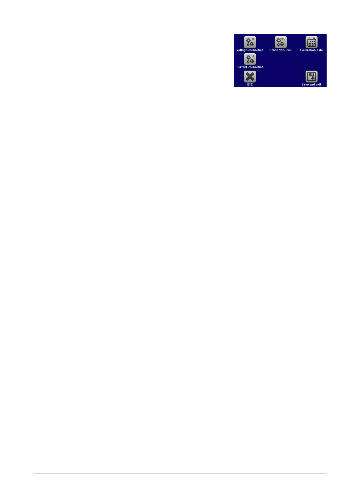
PSI 9000 2U Series
4.3.3.1 Set values
► How to calibrate the voltage
1. Connect a multimeter to the DC output. Connect a load and set its
current to approx. 5% of the nominal current of the power supply, in
this example ~6 A, and 0 V (if the load is electronic).
2. In the display, tap MENU, then „General Settings“, then go to Page
7 and then tap START.
3. IIn the next screen select: Voltage calibration, then Calibrate output
val. and NEXT. The power supply will switch the DC output on, set a
certain output voltage and show the measured value as U-mon.
4. The next screen requests you to enter the measured output voltage from the multimeter at Measured
value=. Enter it using the keypad, that appears when tapping the value. Assure yourself the value is correct
and submit with ENTER.
5. Repeat step 4. for the next three steps (total of four steps).
► How to calibrate the current
1. Set the load to approx. 102% nominal current of the PSI device, for the sample model with 120 A this would
be 122.4 A, rounded to 123 A.
2. In the display, tap MENU, then „General Settings“, then go to Page 7 and then tap START.
3. In the next screen select: Current calibration, then Calibrate output val. and NEXT. The device will switch
on the DC output, set a certain current limit while loaded by the load/sink and show the measured output
current as I-mon.
4. The next screen requests you to enter the output current Measured value= measured with the shunt. Enter
it using the keypad, assure yourself the value is correct and submit with ENTER.
5. Repeat step 4. for the next three steps (total of four steps).
In case you are generally using the remote sensing feature, it is recommended to also calibrate this feature for best
results. The procedure is identical to the calibration of voltage, except for it requires to have the sensing connector
(Sense) on the rear to be plugged and connected with correct polarity to the DC output of the PSI.
► How to calibrate the output voltage for remote sensing
1. Connect a load and set its current to approx. 5% of the nominal current of the power supply, in this example
~6 A, and 0 V (if the load is electronic). Connect a multimeter to the DC terminal of the load and connect the
remote sensing input (Sense) to the DC terminal of the load with correct polarity.
2. In the display of the PSI tap MENU, then „General Settings“, then go to Page 7 and then tap START.
3. IIn the next screen select: Sense volt. cali., then Calibrate output val. and NEXT.
4. The next screen requests you to enter the measured sensing voltage Measured value= from the multimeter.
Enter it using the keypad, that appears when tapping the value. Assure yourself the value is correct and
submit with ENTER.
5. Repeat step 4. for the next three steps (total of four steps).
4.3.3.2 Actual values
Actual values of output voltage (with and without remote sensing) and output current are calibrated almost the
same way as the set values, but here you don’t need to enter anything, just conrm the displayed values. Please
proceed the above steps and instead of “Calibrate outp. value” select “Calibrate actual val.” in the submenus.
After the device shows measured values on display, wait at least 2s for measured value to settle and then tap
NEXT until you are through all steps.
EPS Stromversorgung GmbH
Alter Postweg 101 • 86159 Augsburg
Germany
Fon: +49 821 / 570451-0
Fax: +49 821 / 570451-25
www.eps-germany.de
Page 88
Page 89
PSI 9000 2U Series
4.3.3.3 Save and exit
After calibration you may furthermore enter the current date as “calibration date” by tapping in the
selection screen and enter the date in format YYYY / MM / DD.
Last but not least save the calibration data permanently by tapping .
Leaving the calibration selection menu without tapping “Save and exit” will discard calibration
data and the procedure would have to be repeated!
5. Contact and support
5.1 Repairs
Repairs, if not otherwise arranged between supplier and customer, will be carried out by the manufacturer. For this
the device must generally be returned to the manufacturer. No RMA number is needed. It is sufcient to package
the equipment adequately and send it, together with a detailed description of the fault and, if still under guarantee,
a copy of the invoice, to the following address.
5.2 Contact options
Questions or problems with operation of the device, use of optional components, with the documentation or software, can be addressed to technical support either by telephone or e-Mail.
Address e-Mail Telephone
EPS Stromversorgung GmbH
Alter Postweg 101
86159 Augsburg
Germany
All issues:
Switchboard: +49 821 / 570451-0
EPS Stromversorgung GmbH
Alter Postweg 101 • 86159 Augsburg
Germany
Fon: +49 821 / 570451-0
Fax: +49 821 / 570451-25
www.eps-germany.de
Page 89
Page 90

Page 91

 Loading...