

Page 1
NAVY Evo User Manual
Navy Evo Bedienungsanleitung
2021.08 Version 1.2
Copyright © 2021 ePropulsion. All Rights Reserved
Page 2

Page 3

Acknowledgement
Thanks for choosing ePropulsion products, your trust and support in our company
are sincerely appreciated. We are dedicated to providing high-performance electric
outboards, electric outboards, sup/kayak motors, reliable lithium batteries and accessories.
Welcome to visit www.epropulsion.com and contact us if you have any concerns.
Using This Manual
Before use of the product, please read this user manual thoroughly to understand the
correct and safe operations. By using this product, you hereby agree that you have
fully read and understood all contents of this manual. ePropulsion accepts no liability
for any damage or injury caused by operations that contradict this manual.
Due to ongoing optimization of our products, ePropulsion reserves the rights of constantly adjusting the contents described in the manual. ePropulsion also reserves the
intellectual property rights and industrial property rights including copyrights, patents,
logos and designs, etc.
This manual is subject to update without prior notice, please visit our website www.
epropulsion.com for the latest version. If you find any discrepancy between your
products and this manual, or should you have any doubts concerning the product or
the manual, please visit www.epropulsion.com.
English
ePropulsion reserves the rights of nal interpretation of this manual.
This manual is multilingual, in case of any discrepancy in the interpretation of different language versions, the English version shall prevail.
Symbols
The following symbols will help to acquire some key information.
Important instructions or warnings
Useful information or tips
1
Page 4
Product Identification
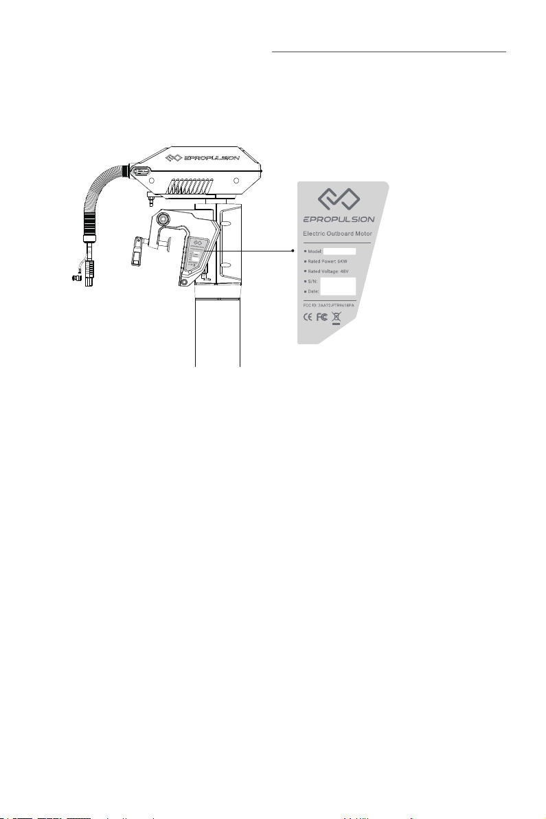
Below picture indicates the serial numbers of NAVY Evo. Please note the position
of the serial numbers and record them for access to warranty service and other after-sale services.
Figure 0-1
2
Page 5

Table of Contents
Acknowledgement ..................................................................................... 1
Using This Manual ..................................................................................... 1
Symbols .................................................................................................... 1
Product Identification ................................................................................ 2
1 Product Overview ................................................................................... 6
1.1 In the Package ......................................................................................... 6
1.2 Parts and Diagram................................................................................... 8
1.3 Specifications .......................................................................................... 9
1.4 Important Notes ................................................................................... 10
1.5 Declaration of Conformity .....................................................................11
2 Preparations ......................................................................................... 12
2.1 Selecting the Battery ............................................................................. 12
2.2 Selecting and Mounting the Propeller ..................................................13
3 Mounting the Outboard Motor ............................................................... 15
3.1 Position of Mounting ............................................................................. 15
3.2 Mounting the Outboard ......................................................................... 16
3.3 Mounting the Steering System ............................................................. 17
3.4 Mounting the Evo Tiller .........................................................................17
English
4 Connecting the Battery ......................................................................... 19
4.1 Connecting a 48V Battery ..................................................................... 19
4.2 Connecting E Series Batteries .............................................................. 20
4.3 Batteries in Series/Parallel ...................................................................22
5 Evo Remote Control/Evo Tiller............................................................... 23
5.1 Display Panel ......................................................................................... 23
5.2 Charging the Evo Remote Control ........................................................ 28
5.2.1 Charging by Solar Power ............................................................. 28
5.2.2 Charging by Wired Connection ...................................................28
5.3 Power Adjusting .................................................................................... 30
5.3.1 Power Adjusting for Evo Control System ................................... 30
5.3.2 Recalibration ................................................................................ 31
3
Page 6

5.4 Use of Kill Switch ................................................................................... 32
5.5 Use of Safety Wristband .......................................................................33
5.5.1 Pairing Safety Wristband with Evo Control System ................... 33
5.5.2 Man Overboard Protection .......................................................... 33
5.5.3 Emergency Stop ........................................................................... 33
5.6 Pairing Evo Control System with the Outboard ...................................34
5.7 Hydro Generation Function ................................................................... 36
5.8 Warning Messages ................................................................................37
6 Configurations ...................................................................................... 39
6.1 Preference Settings ............................................................................... 39
6.2 Battery Configuration ............................................................................ 39
7 Checklist before Use ............................................................................. 42
8 Starting the Outboard ........................................................................... 42
9 Stopping the Outboard .......................................................................... 43
10 Trim Angle Adjusting .......................................................................... 44
11 Anti-grounding Mode .......................................................................... 46
12 Thread the communication cable into the bellow ................................ 47
13 Maintenance ....................................................................................... 49
13.1 Notes .................................................................................................... 49
13.2 Maintenance Time Table ....................................................................49
13.3 Propeller Maintenance ........................................................................ 50
13.4 Replacing the Anode ........................................................................... 50
14 Transportation and Storage ................................................................ 52
14.1 Transport..............................................................................................52
14.2 Placement ............................................................................................ 52
14.3 Storage .................................................................................................52
15 Emergency Situations ......................................................................... 53
15.1 Collision ............................................................................................... 53
15.2 Sodden Outboard ................................................................................ 53
15.3 Low Battery Level ................................................................................ 53
15.4 Over-temperature Protection .............................................................. 53
4
Page 7

16 Warranty ............................................................................................ 54
16.1 Warranty Policies.................................................................................54
16.2 Out of Warranty ...................................................................................55
16.3 Warranty Claim Procedures ................................................................ 55
English
5
Page 8
1 Product Overview
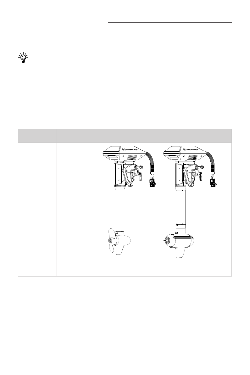
NAVY 6.0 Evo is a 6kW electric outboard motor, and NAVY 3.0 Evo is a 3kW electric
outboard motor.
Evo control system is necessary when operating the outboard motor, but it is not
included in the NAVY Evo. It need be purchased separately by users from ePropulsion authorized dealers.
1.1 In the Package
Unpack the package and check if there is any damage caused during transport.
Check all the items inside the package against the below list. If there is any transport
damage or lack of any listed item, please contact your dealer immediately.
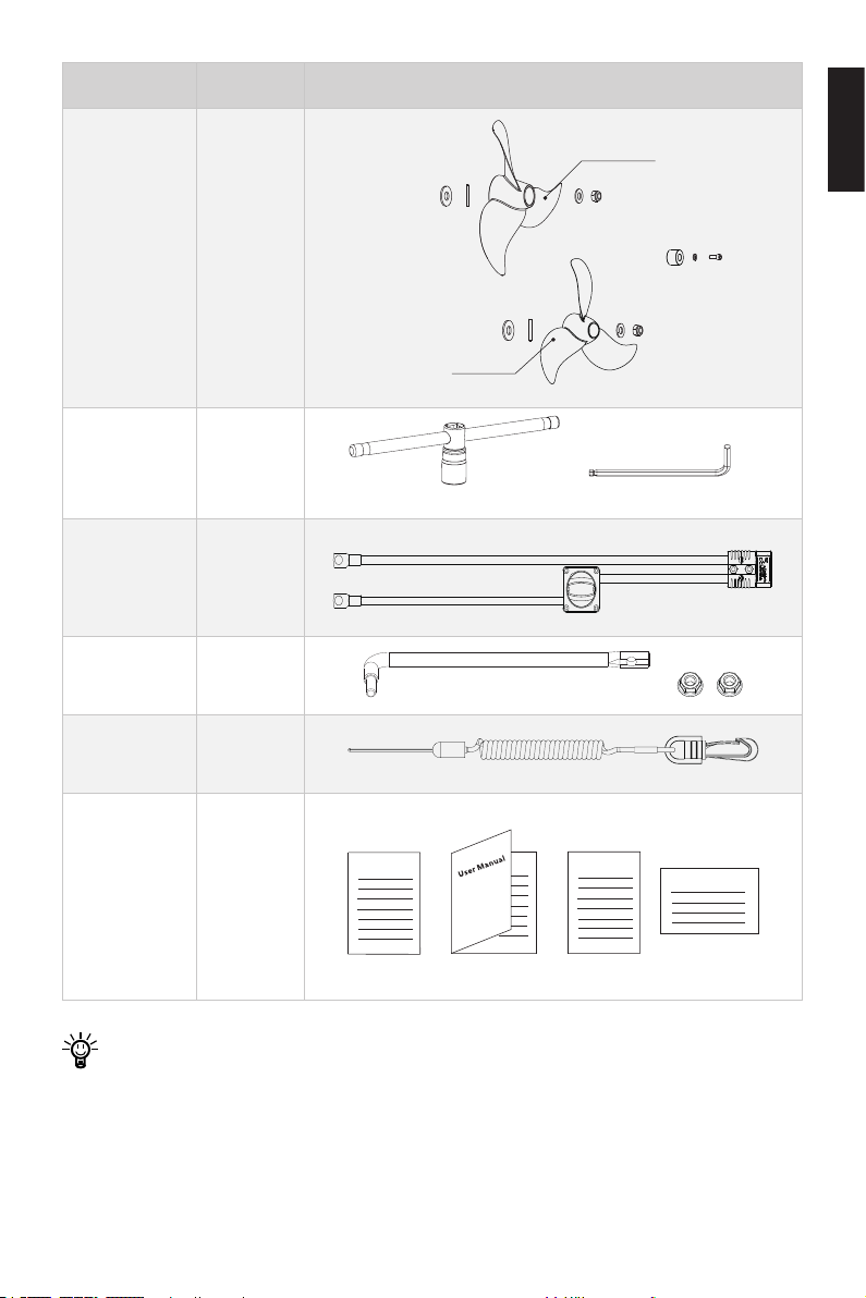
Items Qty./Unit Figure
Outboard
(Main part)
1 set
NAVY 3.0 Evo NAVY 6.0 Evo
6
Page 9
Items Qty./Unit Figure
High Pitch Propeller
Propeller
Assy.
(delivered
2 Sets
with NAVY
6.0 Evo)
Low Pitch Propeller
Wrench Set 1 Set
19mm Wrench M6 Wrench
Main Switch
Cable
1 Set
Link Arm 1 Set
Tiller Shaft
Lanyard Evo
1 Piece
English
User Manual,
Warranty
Card, Quality
Certicate
Warranty
1 Set
Quality
Certificant
Invitation Card
& Invitation
Card
Other accessories not included in the package are also required to operate the
outboard motor, such as Evo control system, battery, charger and communica-
tion cable, etc. Users can buy ocial accessories provided by ePropulsion such
as Evo Remote Control, Evo Tiller, E Series Battery, E battery Charger and communication cable, etc. from ePropulsion authorized dealers.
7
Page 10
Note that the propeller of NAVY 3.0 Evo is attached on the motor before delivery
Tiller shaft
Tiller shaft
and the two propellers of NAVY 6.0 Evo in the package differ in specications:
the high-pitch propeller (Diameter: 320mm/12.6inch, Pitch: 10.8inch) and the
low-pitch propeller (Diameter: 340mm/13.4inch, Pitch: 8.5inch). They share the
accessories.
Save ePropulsion original package for transport and storage.
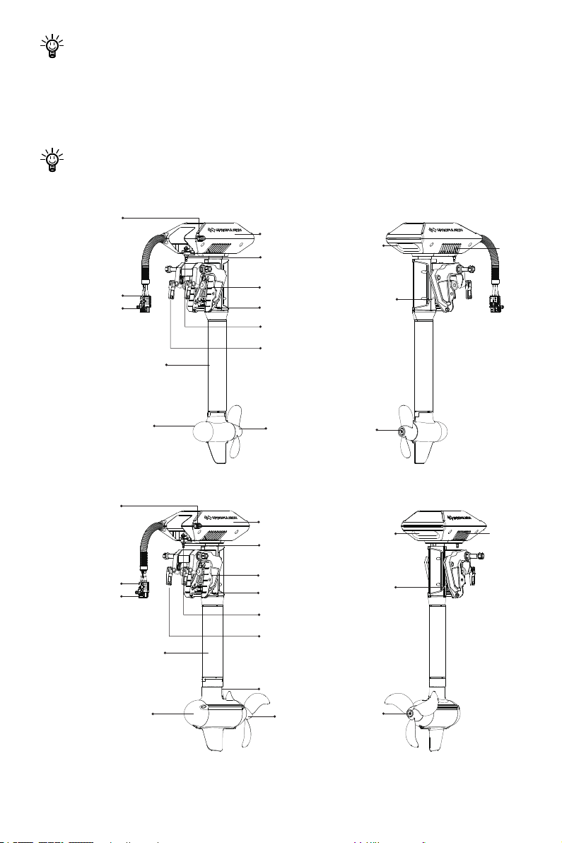
1.2 Parts and Diagram
Communication
Power Cable
Communication
Power Cable
Cable
Connector
Cable
Connector
Shaft
Motor
Shaft
Motor Case
Mount Position
of Link Arm
Bracket Clamp
Beaching Lever
Communication Port
Tightening Handle
for Clamp
Propeller
Lifting Handle
Figure 1-1 NAVY 3.0 Evo
Motor Case
Mount Position
of Link Arm
Bracket Clamp
Beaching Lever
Communication Port
Tightening Handle
for Clamp
Lifting Handle Fan
Fan
Trim Lever
Anode
Trim Lever
Motor
Anode
Propeller
Figure 1-2 NAVY 6.0 Evo
8
Anode
Page 11
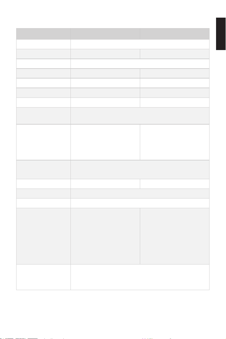
1.3 Specifications
NAVY 3.0 Evo-S/L NAVY 6.0 Evo-S/L
Type Electric Outboard Motor
Input Power 3 kW 6 kW
Rated Voltage 48 V
Input Voltage 39 V ~ 60 V DC 39 V ~ 60 V DC
Equivalent Power 6 hp 9.9 hp
Max Overall Eciency 51% 57%
Rated Rotation Speed 2300 rpm 1500 rpm
Control System
Dimension (L×W×H)
Evo Remote Control / Evo Tiller / Evo Side Mount Control /
Evo Dual Remote Control
S: 437 × 314 × 1049 mm /
17.2 × 10.7 × 41.3 inches
L: 437 × 314 × 1174 mm /
17.2 × 10.7 × 46.2 inches
S: 547 × 314 × 1087 mm /
21.5 × 10.7 × 42.8 inches
L: 547 × 314 × 1212 mm /
21.5 × 10.7 × 47.7 inches
English
Shaft Length
Weight 24.3 kg(S)/25.1 kg(L) 36 kg (S) / 36.8 kg (L)
Trim Angles Manual, 0°, 5°, 10°, 15°
Tilt Angle Manual, 60°
Propeller (Diameter ×
Pitch)
Recommended Operating Ambient Temperature
10.2″ × 6.7″ 2-blade composite propeller
S: 634 mm / 25 inches
L: 759 mm / 29.9 inches
12.6″ × 10.8″ 3-blade compo-
site propeller
13.4″ × 8.5″ 3-blade composite propeller
12.6″ × 8.7″ 3-blade aluminum propeller (Optional)
-10°C to 45°C
14˚F to 113˚F
9
Page 12

1.4 Important Notes
1. Check the status of the outboard and battery level before each trip.
2. The distance and speed value displayed is measured by Global Positioning
System (GPS), there may exist small errors due to GPS signal strength
degradation or some external environment conditions like currents, winds and
change of course.
3. Ensure the top of outboard is uncovered to avoid GPS signal attenuation.
4. Familiarize yourself with all the outboard operations, including starting, steering,
stopping, trim adjusting and tilting.
5. Only adults who have fully read and understood this manual are allowed to
operate this product.
6. Follow the boat manufacturer’s instructions to choose a suitable outboard. Do
not overload neither the boat nor the outboard.
7. Stop the outboard immediately if someone falls overboard during the trip.
8. Protect the battery from dropping into water or short-circuiting.
9. Follow the battery manufacturer’s instructions and pay attention to short circuit,
over-heat, over-charge and over-discharge.
10. Operate the outboard only when the propeller is underwater.
11. Tilt up the outboard motor above water after use.
12. Wash the outboard in time with fresh water after sailing in salt water.
13. Clean all electronic contacts with contact spray about every two months.
14. Do not leave the outboard in water if the boat speed reaches 30km/h which is
driven by other power such as sailing or rowing.
15. An error code will display on the panel if the outboard malfunctions. Put the
throttle to zero position and turn off the main switch, then refer to Chapter 5.8
Warning Messages for details and solutions.
16. For safety consideration, the system will shut down automatically when the
temperature of the motor or driver rise too high or the battery voltage drops too
low during operation.
17. Users are responsible to assemble the propeller and steering wheel. If other
assembly or disassembly is required, please contact your dealer. ePropulsion
accepts no liability for any damage or malfunction caused by operations that
violate this manual.
10
Page 13

1.5 Declaration of Conformity
Object of the Declaration:
Product: Electric Outboard
Model: NAVY 6.0 Evo, NAVY 6.0 Evo-L, NAVY 6.0 Evo-S, NAVY 6.0 Evo-C, NAVY 3.0
Evo, NAVY 3.0 Evo-L, NAVY 3.0 Evo-S, NAVY 3.0 Evo-C
Company Name: Guangdong ePropulsion Technology Limited
Address: Room 201, Bldg.17A, 4th XinZhu Road, SongShan Lake District, Dongguan
City, Guangdong Province, China
The object of the declaration is in conformity with the following directives:
EMC-directive 2014/30/EU
MD-directive 2006/42/EC
RED-directive 2014/53/EU
Applied Standards:
EN 55014-1:2017 EN 300328:2019
EN 55014-2:2015 EN 50663:2017
EN 61000-3-2:2014 EN 62368-1:2014+A1:2017
EN 61000-3-3:2013/A1:2019 EN 60204-1:2018
EN 301489-1:2019 EN ISO 12100:2010
EN 301489-3:2019
This device complies with part 15 of the FCC Rules: Operation is subject to the following two conditions:
1. This device may not cause harmful interference and,
2. This device must accept any interference received, including interference that
may cause undesired operation.
English
Signature:
Shizheng Tao, Chief Executive Ocer & Cofounder of
Guangdong ePropulsion Technology Limited
11
Page 14
2 Preparations
2.1 Selecting the Battery
It is recommended to use ePropulsion E Series Batteries.
Lithium-based and lead-acid batteries can be used to supply power for NAVY Evo.
Considering the high performance in energy density and discharge ability, lithium-based batteries are more preferable. To ensure that NAVY Evo can work at its full
power continually, the batteries are required to possess over 62.5A(NAVY 3.0 Evo) or
125A(NAVY 6.0 Evo) of continuous discharge current. To ensure at least one hour of
duration, the battery capacity should reach 3000Wh(NAVY 3.0 Evo) or 6000Wh(NAVY
6.0 Evo) or above.
The rated continuous discharge current is affected by the battery type and quantity
of parallel batteries. To use lead-acid batteries, conventional lead-acid or AGM or GEL
batteries are acceptable, while starter batteries are not recommended. Traction batteries or deep cycle batteries are more preferable as they give power over sustained
period of time. Besides, the deep cycle marine batteries are also capable.
Battery capacity is a major factor that affects trip duration and distance. For instance,
a battery with 48V of rated voltage completely discharges at a continuous current
of 125A in 1 hour, so its rated capacity is 6000Wh (125Ah*48V=6000Wh), we also
can say its rated capacity is 125Ah. The maximum power of NAVY 6.0 is 6kW which
means the system can be running at full power for about 1 hour when using this
battery. You can select a battery with proper capacity based on your requirements
for travelling time and distance. Note that the operating time and distance are also
affected by the input power of the outboard plus the external environment and temperature. In addition, boat type and load also play important roles.
Users can connect four 12V batteries in series to make a 48V battery set and use it
to supply power for NAVY 6.0. Users can also enlarge the battery capacity by parallel
conguration.
When using E Series Batteries, the batteries will work well once being correctly
connected. When using non-ePropulsion batteries, before starting the outboard,
users should congure the batteries via the Evo Control System for the rst time
use, otherwise the batteries may not work properly.
12
Page 15
Only use the same batteries (same model, same capacity, same age and same
manufacturer) in series or in parallel configuration. Variations in the batteries
will cause damage to them.
2.2 Selecting and Mounting the Propeller
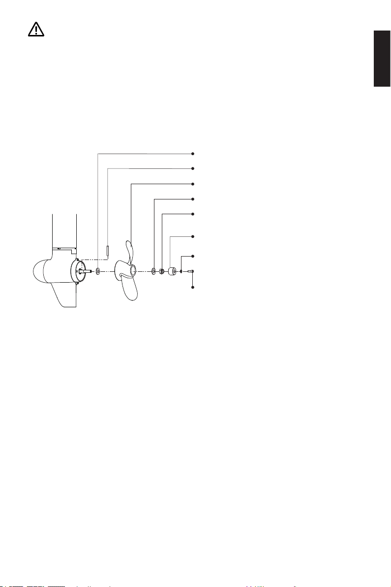
For NAVY 3.0 Evo, the propeller of NAVY 3.0 Evo is attached on the motor before delivery. If necessary to replace a propeller, please follow the steps below to replace and
mount the propeller.
Step1: Attach the Φ12 washer.
Step2: Fix the pin to the hole of shaft.
Step3: Attach the propeller.
Step4: Attach the Φ12 washer.
Step5: Tighten the nut with 19mm (3/4 inch)
socket wrench.
Step6: Attach the Anode.
Step7: Attach the Φ6 washer.
Step8: Screw and tighten the nut
with M6 hexagon wrench.
English
Figure 2-1
For NAVY 6.0 Evo, there are two types of propellers are available. Users can select a
proper propeller based on different conditions. For a heavily loaded boat with large
thrust, a low pitch propeller is more appropriate. Inversely, for a lightly loaded boat
with a fast running speed, a high pitch one is preferable.
In the delivery package, there are two sets of propellers, including a low-pitch propeller and a high-pitch propeller. The low-pitch propeller with a larger diameter generates
larger thrust at low speed, while the high-pitch propeller generates proper thrust to
propel boats at high speed. It is recommended to use the high-pitch propeller if the
boat speed can reach 15km/h or above, as the propeller can’t work at full performance at low speed. Figure 2-1 displays how to mount a propeller correctly.
13
Page 16
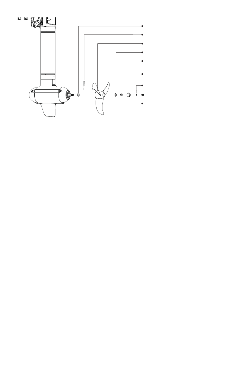
Figure 2-2
Step1: Attach the Φ16 washer.
Step2: Fix the pin to the hole of shaft.
Step3: Attach the propeller.
Step4: Attach the Φ12 washer.
Step5: Tighten the nut with 19mm
(3/4 inch) socket wrench.
Step6: Attach the Anode.
Step7: Attach the Φ6 washer.
Step8: Screw and tighten the nut
with M6 hexagon wrench.
14
Page 17
3 Mounting the Outboard Motor
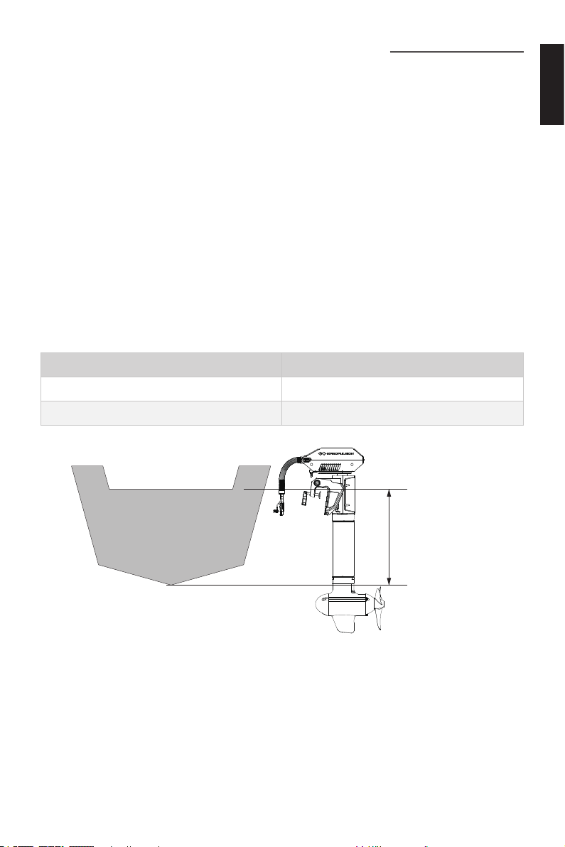
Select an outboard with proper shaft length according to the transom height of your
boat. The top of the propeller should be 100mm to 150mm below the water.
The outboard should be mounted on the centerline of your boat. If the boat shape is
asymmetric, please consult your dealer for proper solution.
3.1 Position of Mounting
The mounting height of the outboard affects the running speed seriously. When the
mounting height is too high, cavitation may occur, which may lead to speed slowdown, energy waste, and propeller damage. When the mounting height is too low, the
water resistance will reduce both travelling speed and performance of the outboard.
In general, the optimal mounting height is affected by the specific conditions of a
boat. In order to get the optimal mounting height, it’s suggested to test running by
mounting the outboard at different heights. Please consult your dealer for more help.
Transom Height Recommended Model
Higher than 500mm NAVY 3.0 Evo-L / NAVY 6.0 Evo-L
400mm~500mm NAVY 3.0 Evo-S / NAVY 6.0 Evo-S
English
Figure 3-1 NAVY 6.0 Evo
15
Top of boat transom
Transom height
Bottom of boat
(lowest point)
Page 18
3.2 Mounting the Outboard
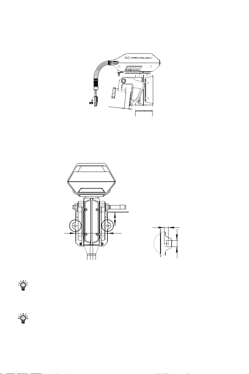
Method 1
Rotate the two clamps in clockwise direction to x the outboard onto transom.
30~70mm
Figure 3-1
Method 2
Use two screws to x the outboard to the boat. The dimensions of the two mounting
holes are shown below.
86mm
Top of boat transom
10mm
175mm
16mm
Figure 3-2
Ensure the outboard is firmly fixed as loosened clamp screws may cause the
outboard to fall into water or get damaged. Check the screws or clamps every
time before use since they may be loosened because of mechanical vibrations.
A cable is recommended to be used to avoid complete loss of your outboard in
case it falls off the transom. Use the cable to connect your outboard and a se-
cure mounting point on the boat.
16
Page 19
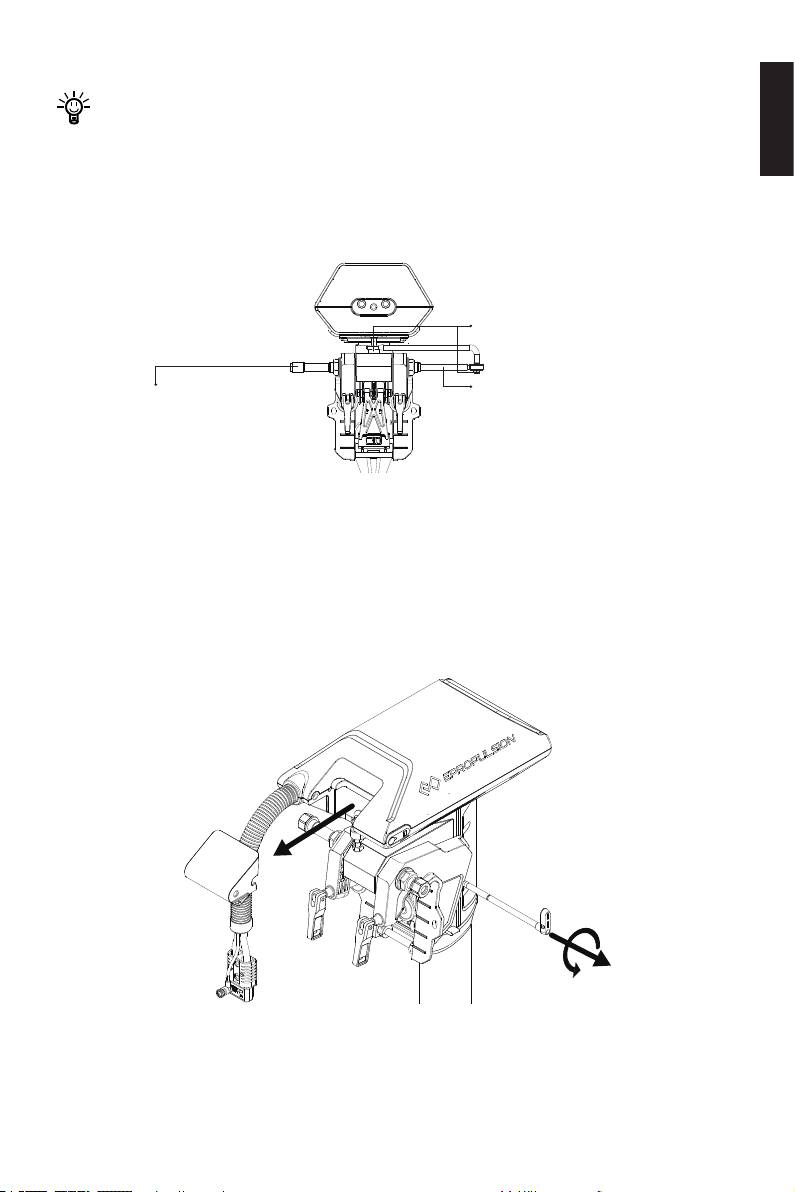
3.3 Mounting the Steering System
Step2: Mount the Link arm with
two M8 nuts.
Step3: Fasten the steering wheel
shaft on the steering tube
with thread.
Step1: Insert the steering wheel
shaft into the steering tube.
Before using Evo Remote Control, please follow the xing guide to x the Evo Re-
mote Control in the proper position.
When using the Evo Remote Control, please prepare a steering wheel (not supplied
with NAVY Evo or the Evo Remote Control) and mount it on the corresponding position to control the direction.
Figure 3-3
3.4 Mounting the Evo Tiller
1. Rotate the handle shaft counterclockwise, then pull out the handle shaft and
decorative cover.
English
Figure 3-4
17
Page 20
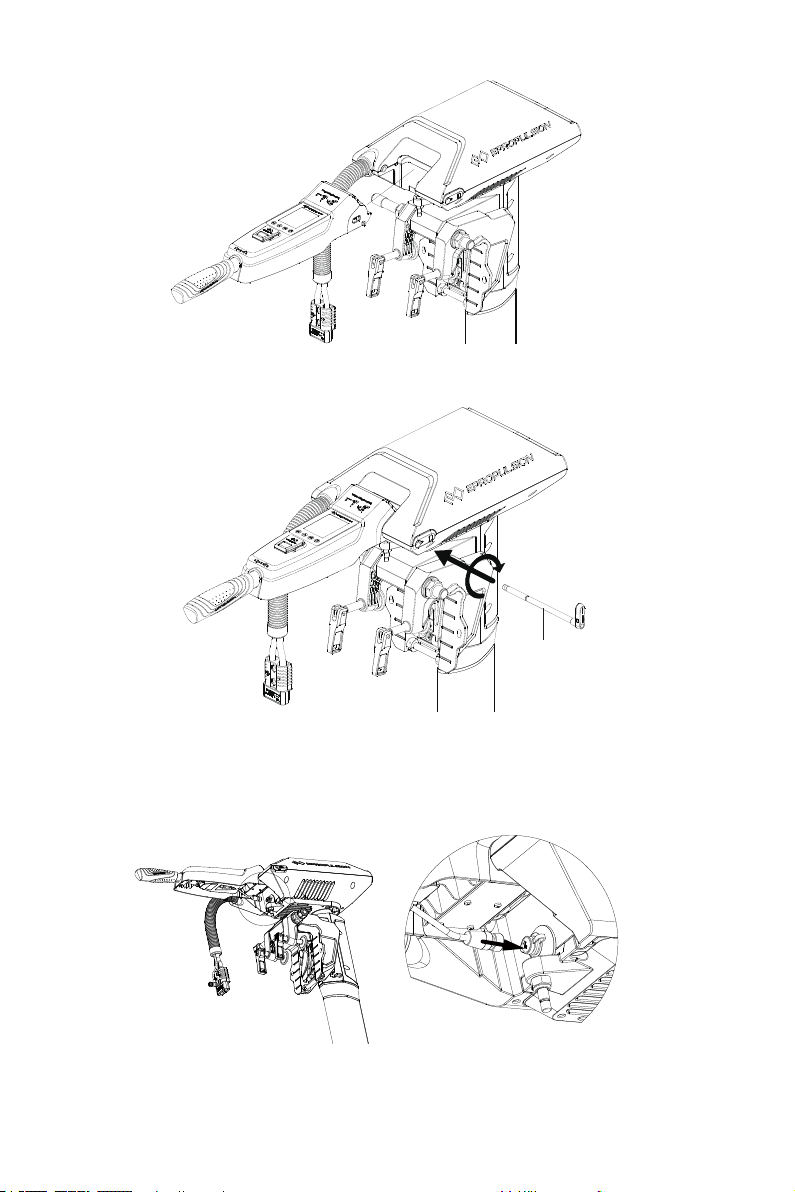
2. Install the tiller to the machine.
Figure 3-5
3. Insert the handle shaft into the hole to the end and lock it clockwise.
Handle Shaft
Figure 3-6
4. Connect the communication cable of Evo Tiller to the communication port of the
NAVY Evo.
Figure 3-7
18
Page 21
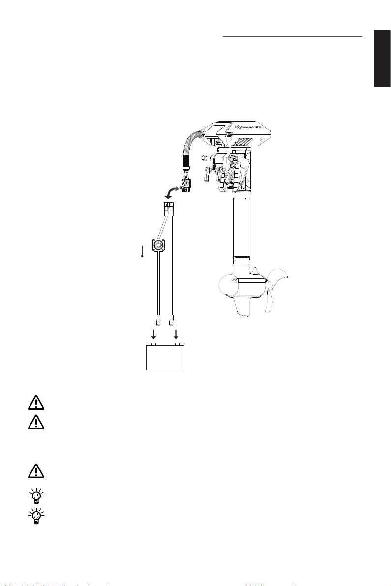
4 Connecting the Battery
Main
Switch
①
②
+ -
48V
+ -
4.1 Connecting a 48V Battery
When using a battery, make sure the main switch is off before connection.
1. First connect the main switch cable to the battery.
2. Connect the main switch cables with the power cable from the outboard.
English
Figure 4-1
Avoid battery short-circuit during connection.
Do not short-circuit the main switch with other power supplies. The main switch
should be mounted on the boat, and the back plate of the main switch should
not be removed.
Outboard motor will stop working once the power cable disconnects.
Clockwisely rotate the main switch to power on the battery before use.
Users can also enlarge the battery capacity by connecting multiple batteries in
parallel.
19
Page 22
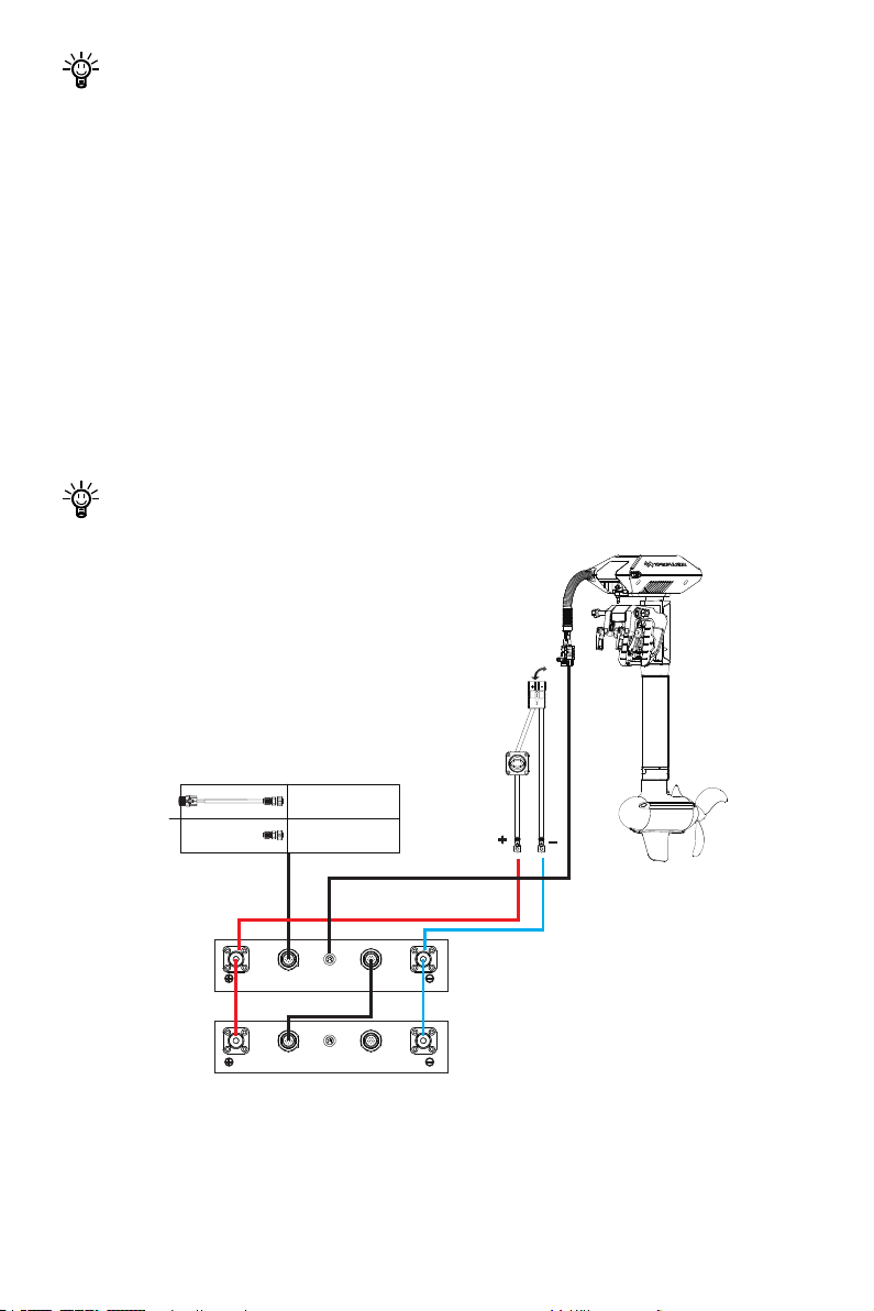
The main switch and power cable are connected by the xing screws that may
CAN-IN CAN-OUTMOTOR
CAN-IN CAN-OUTMOTOR
Remote Switch
Communication
Terminator
E Battery
E Battery
E Battery
communication cable
loosen after long-time use. Loosen screws will lead to poor contact, which may
result in overcurrent or other errors. If this problem is discovered, open the back
cover of the switch, and tighten the screws inside.
4.2 Connecting E Series Batteries
When using E Series Batteries, make sure the main switch is off before connection.
1. First connect two batteries in parallel by a communication cable and two battery
bridging cables.
2. Connect the main switch cable to the E Series Battery.
3. Connect the main switch cable with the power cable from the outboard.
4. Connect NAVY Evo outboard motor to the E Series Battery with a communication
cable.
It's recommended to connect the communication cable to obtain accurate bat-
tery information.
Figure 4-2
20
Page 23

Avoid battery short-circuit during connection.
Do not short-circuit the main switch with other power supplies. The main switch
should be mounted on the boat, and the back plate of the main switch should
not be removed.
NAVY Evo outboard motor will stop once the power cable disconnects.
Use communication cables to connect E Series Batteries when multiple E Series
Batteries are used in parallel.
Clockwisely rotate the main switch to power on the battery before use.
Users can also enlarge the battery capacity by connecting multiple batteries in
parallel.
The main switch and the power cable are connected by the xing screws that
may loosen after long-time use. Loosen screws will lead to poor contact, which
may result in overcurrent or other errors. If this problem is discovered, open the
back cover of the switch, and tighten the screws inside.
English
21
Page 24
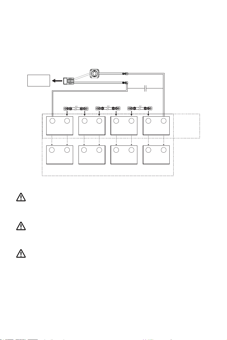
4.3 Batteries in Series/Parallel
When connecting four 12V batteries in series to make a 48V battery set to supply
power for NAVY Evo, use bridging cables to connect batteries in series (Figure 4-3).
Make sure to connect the main switch cable to battery positive terminal and the other
cable to battery negative terminal.
Outboard
Motor
Bridging
-
+
12V
- +
12V
Parallel
Connection
Cable
-
12V
- +
12V
Bridging
Cable
+
- +
12V
- +
12V
48V
Bridging
Cable
- +
12V
- +
12V
Serial
Connection
Figure 4-3
Do not short-circuit the main switch with other power supplies. The main switch
should be mounted on the boat, and the back plate of the main switch should
not be removed.
Only use the same batteries (same model, same capacity, same age and same
manufacturer) in series and/or in parallel. Variations in batteries will cause dam-
age.
Never reverse the polarity. Please pay more attention when connecting batteries
in series and/or in parallel configuration. Always double check by referring to
Figure 4-3.
22
Page 25
5 Evo Remote Control/Evo Tiller
The Evo Remote Control and Evo Tiller is used for starting and stopping the outboard
motor, adjusting the speed of the motor, conguring the battery parameters, displaying the system information and messages, etc. The Evo Remote Control is powered
by either solar power or the built-in lithium battery, but the Evo Tiller is powered by
connecting to the outboard with a communication cable. Evo Remote Control wirelessly or wiredly communicates with the outboard control system built in the main
outboard motor, and Evo Tiller can only wiredly communicate with the outboard. The
Evo Tiller itself owns the steering capability, while using the Evo Remote Control, it
requires an additional steering wheel to help steer.
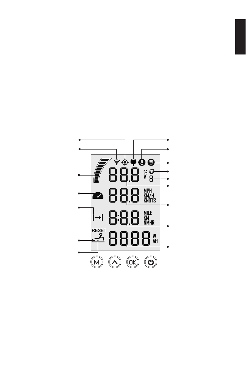
5.1 Display Panel
English
GPS Status Indicator
Wireless Connecting Indicator
Battery Level Indicator
Fan Fault
Travelled Distance / Time or
Remaining Distance / Time
Throttle Reset Indicator
Low Power Indicator of
Remote Control
Figure 5-1
Hydrogeneration Indicator
Overheat Alert
Kill Switch Status Indicator
Safety Wristband Status
Indicator
Number of Safety Wristband
Battery Level / Voltage
Current Speed
Distance / Time
Throttle Power
23
Page 26
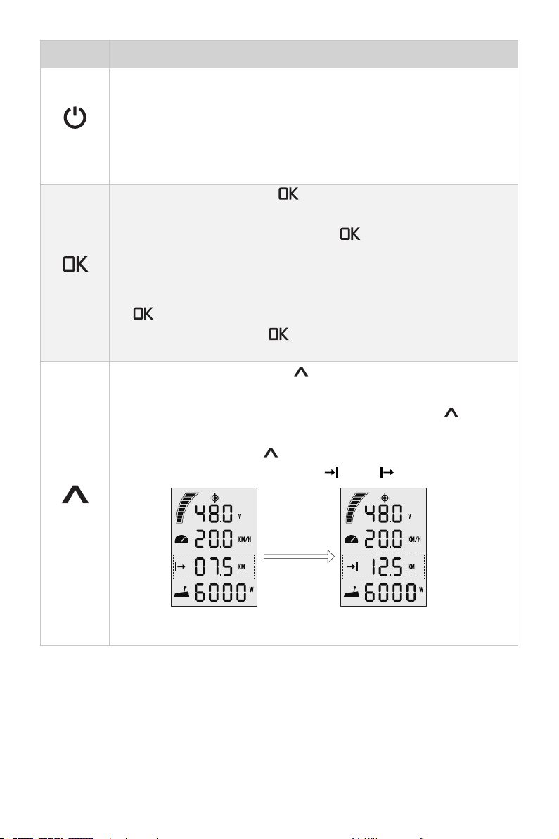
Buttons Functions
1. In power-off state, press and hold the power button to power on
the Evo Remote Control or Evo Tiller.
2. In power-on state, press and hold the power button to power off
"Power"
“OK”
the Evo Remote Control or Evo Tiller.
3. In power-on state, press the power button to switch on or off the
backlight of Evo Remote Control or Evo Tiller.
1. On setting pages, press " " button to save the current settings
and switch to the next item.
2. On setting pages, press and hold " " button, and the system
will save your settings, the display will exit from setting page and
return to the home page.
3. If home page displays or all characters display on the page, press "
" button and hold 5s to enter the pairing page.
4. On home page, press " " button to switch between voltage V
and battery percentage %.
1. On any setting page, press "
setting.
2. In power-on state, when home page displays, press "
and hold 10s to enter the throttle calibration page.
3. On home page, press "
or time displaying icon between " " and " ".
" button to view options for current
" button to switch the travelling distance
" button
"Up"
press
“Up”
button
Main page 1 Main page 2
24
Page 27
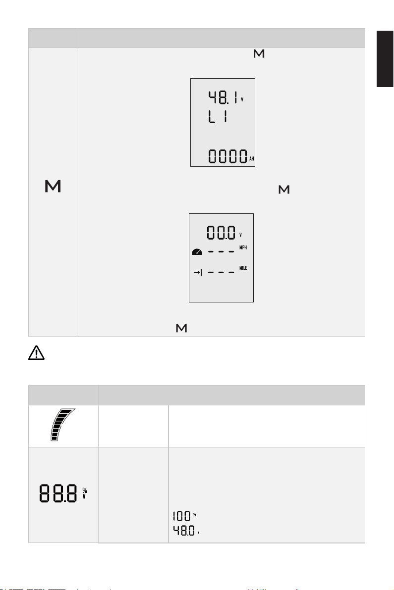
Buttons Functions
1. In power-on state, press and hold “ ” button to enter the
preference setting page.
Preference setting page
2. On preference setting page, press and hold “ ” button to enter
"Menu"
the battery setting page.
Battery setting page
English
3. On any page, press “ ” button to return home page.
If users enter the page without setting any parameters, the current parameters
displayed on the page will be saved as user parameters by default.
Icons Functions
Battery level
indicator
Battery level/
voltage
Indicating approximate battery level. The solid
blocks stand for remaining battery.
Indicating accurate current battery level percentage/battery voltage, is congurable in preference setting page.
For example:
: indicates current battery level.
: indicates current battery voltage.
25
Page 28
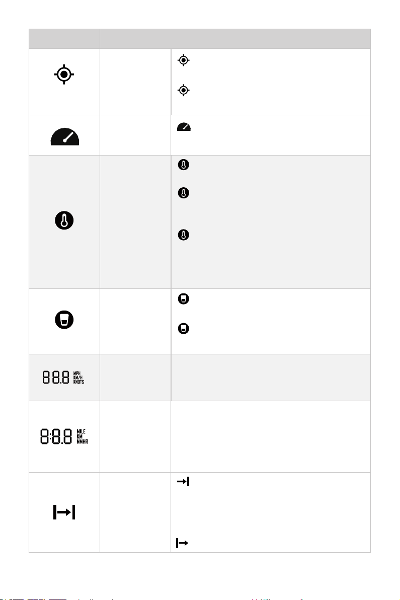
Icons Functions
Hidden: no satellite signal is received or
GPS status
indicator
GPS does not work.
Blink: GPS is connecting to satellites.
Shown constantly: GPS is in use.
Fan fault
Over-heat alert
Kill switch status indicator
Current speed
Distance/time
display
Blink:The motor fan has faults. Please contact the dealer to check the fan wiring.
Hidden: system temperature is in normal
range.
Blink: system temperature is a little high
and the maximum input power of motor
has been lowered
Shown constantly: system is over temperature and the outboard will stop working.
The outboard can’t be started until the system temperature drops to a certain level.
Hidden: kill switch is present and is working well.
Shown constantly: the kill switch is detached.
Displaying real time cruising speed. Set units
(KM/H,MPH or KNOTS) in preference setting
page.
Displaying real time travel distance/time. Set
units (MILE, KM (kilometer) and NM (nautical
mile)) in preference setting page.
The time unit is HR (hour).
Travelled distance/time
or remaining
distance/time
: Remaining distance or time that the outboard can travel.
Set units (MILE, KM (kilometer) and NM (nautical mile)) in preference setting page.
: Travelled distance or time.
26
Page 29
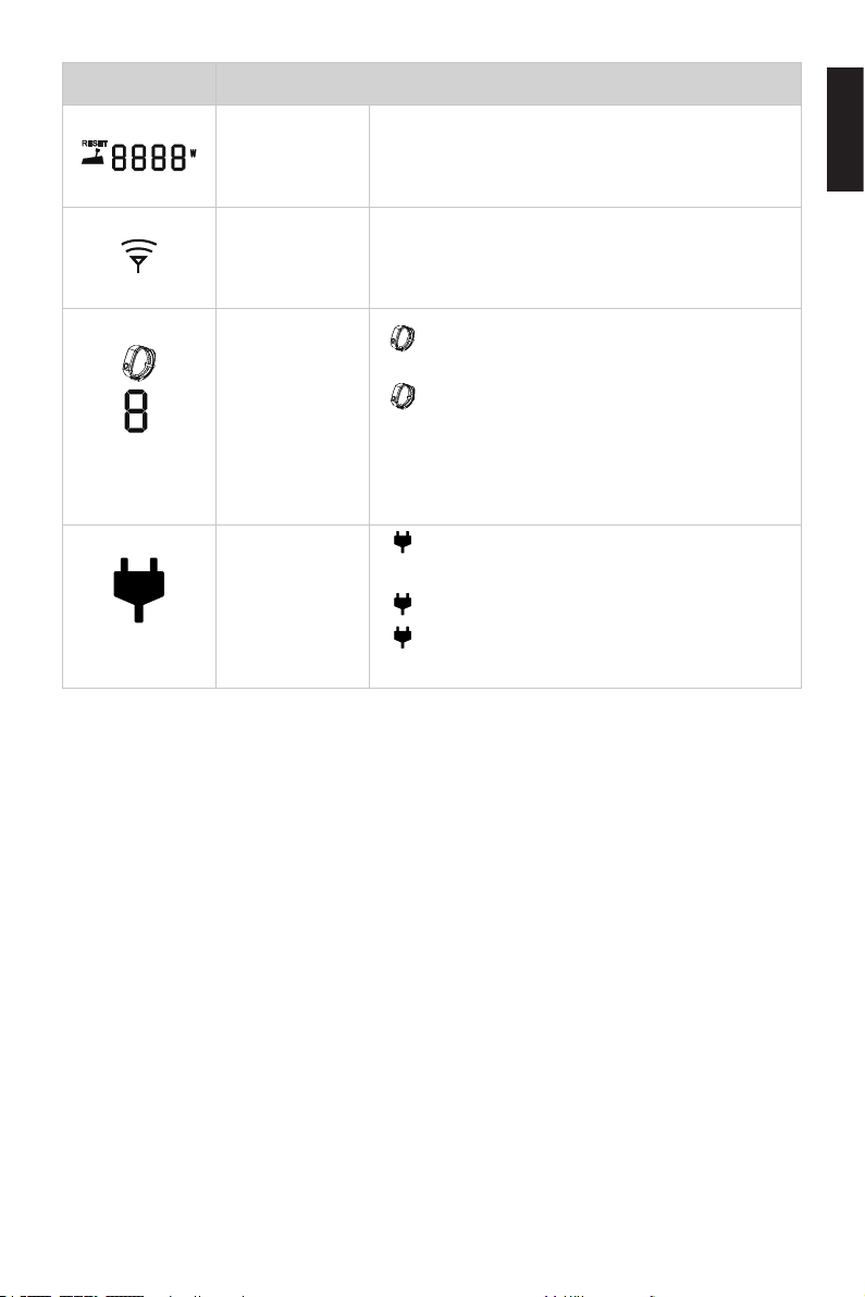
Icons Functions
Displaying real time input power to the system.
Throttle Power
Wireless
connecting
indicator
Safety wristband connecting display
Hydro generation indicator
A blinking “RESET” indicating the throttle should
be reset to zero position.
Displaying the remote control is wireless
connecting with outboard.
Shown constantly: the safety is connecting with the remote control successfully.
Blink: there is a safety wristband to dis-
connect.
The number indicates the number of safety
wristbands connected to the remote control.
Shown constantly: the hydro generation
function is turned on.
Blink: the machine is charging the battery.
Hidden: the hydro generation function is
turned off.
English
27
Page 30
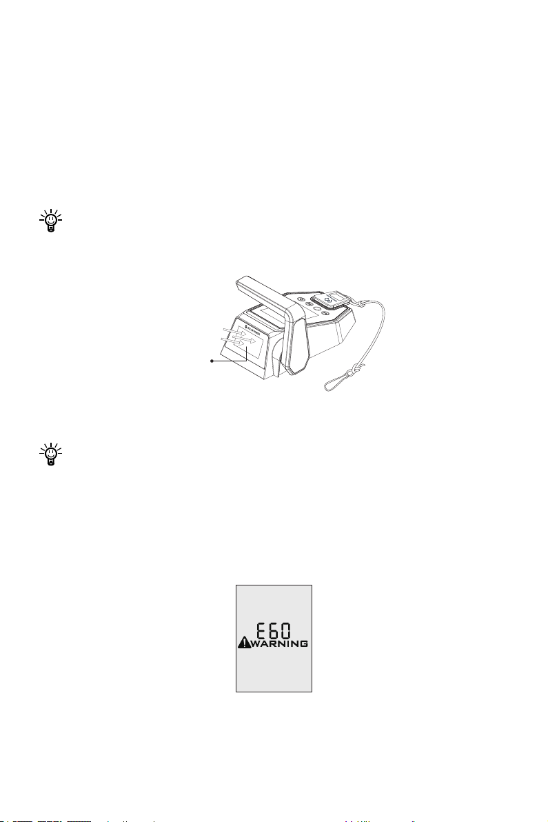
5.2 Charging the Evo Remote Control
The Evo remote control has an in-built lithium battery for power supply. The battery
will be charged automatically under normal use: get charged by solar power or wired
connection.
5.2.1 Charging by Solar Power
When the solar panel receives enough sunshine, it will generate electricity to charge
the in-built lithium battery.
Face the solar panel of the Evo remote control toward sunlight to get better
charging effect.
^
Solar Panel
(Face the Sun)
Figure 5-2
Charging by solar power is recommended.
5.2.2 Charging by Wired Connection
If the Evo remote control can’t get enough solar power for a long time, the battery will
run out. In this case, error code E60 (Figure 6-3) will display to remind you to charge
the Evo remote control.
Figure 5-3
28
Page 31
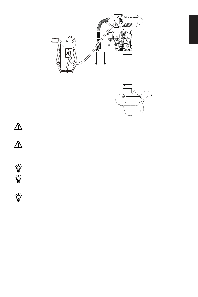
Battery
Communication
Cable
Figure 5-4
During long-term storage, ensure to charge the control system every 6 months to
avoid over-discharge.
Do not short-circuit the main switch with other power supplies. The main switch
should be mounted on the boat, and the back plate of the main switch should
not be removed.
After long-term storage, charge the control system before use.
The communication cable is not included in this package. Please purchase one
from your dealer if you choose this charging method.
English
Once the communication cable disconnects, charging automatically stops and
the running motor stops. Please restart the motor.
29
Page 32
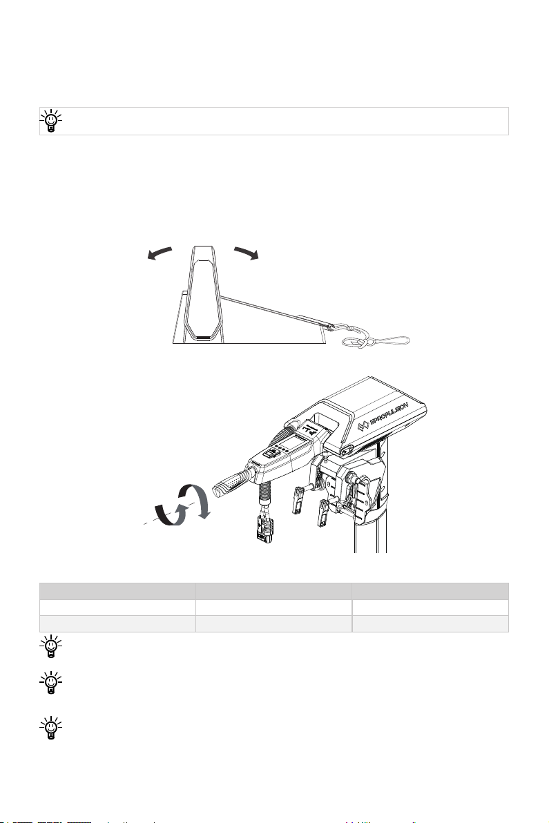
5.3 Power Adjusting
Forward
Zero position
Backward
Evo Remote Control
5.3.1 Power Adjusting for Evo Control System
Please place the safety switch on the Evo control system before operation.
The Evo Control system is mainly used to adjust the input power of the motor. When
the battery is well connected and switched on, power on the control system to start
the outboard, then slowly push/rotate the throttle forward position to increase the
power. The maximum forward/backward power is shown below.
Figure 5-5
Backward
Forward
Neutral
Figure 5-6
Model Max Forward Power Max Backward Power
NAVY 3.0 Evo 3 kW 3 kW
NAVY 6.0 Evo 6 kW 6 kW
Before power on the Control system, please reset the throttle to zero position.
If you nd a blinking “RESET” on the display panel, you are reminded to reset the
throttle to zero position.
If you pull the throttle from the forward position to the backward position direct-
ly, the motor will rst stop shortly, then start turning to the reverse direction.
30
Page 33
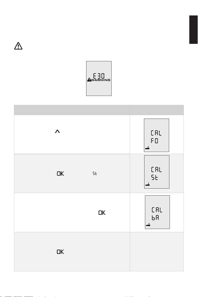
5.3.2 Recalibration
If the error code displays as the gure 5-7, users should calibrate the throttle strictly
as below steps.
Before calibration, please attach the kill switch in the package to the proper position. It is forbidden to use other magnets to replace the kill switch for calibration.
Figure 5-7
Recalibration process LCD Displaying
Step1: Long press “
displays.
Step2: Push the throttle to the maximum forward power
position, then press " " button. “CAL ” will display
and “CAL” will be blinking.
” button for 10s until “CAL FO”
English
Step3: Pull the throttle to the middle (zero) position where you can hear a click sound, then press " "button,
“CAL bA” will display and “CAL” will be blinking.
Step4: Pull the throttle to the maximum backward power
position, then press " " button. It will return to the main
page automatically.
31
Page 34
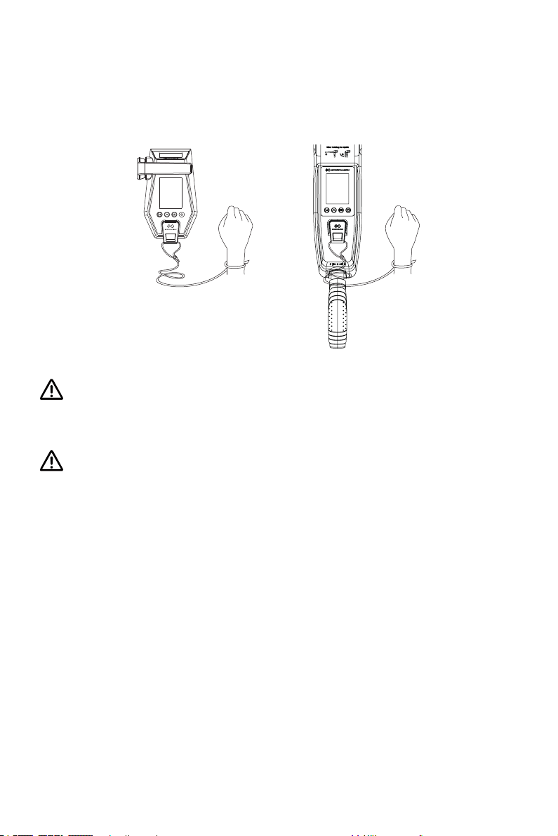
5.4 Use of Kill Switch
• Attach the kill switch and tie its lanyard to your wrist or life jacket.
• Stop the outboard in emergency by detaching the kill switch.
• To run the motor again, first attach the kill switch then start the motor.
Figure 5-8
The kill switch generates magnetic field. Keep it 50cm / 20inches away from
medical implants like pacemakers and magnetic cards (e.g. credit card) as well
as other magnetic media.
The magnetic eld of the kill switch may interfere with some electronic instruments. Keep it away from these electronic instruments.
32
Page 35
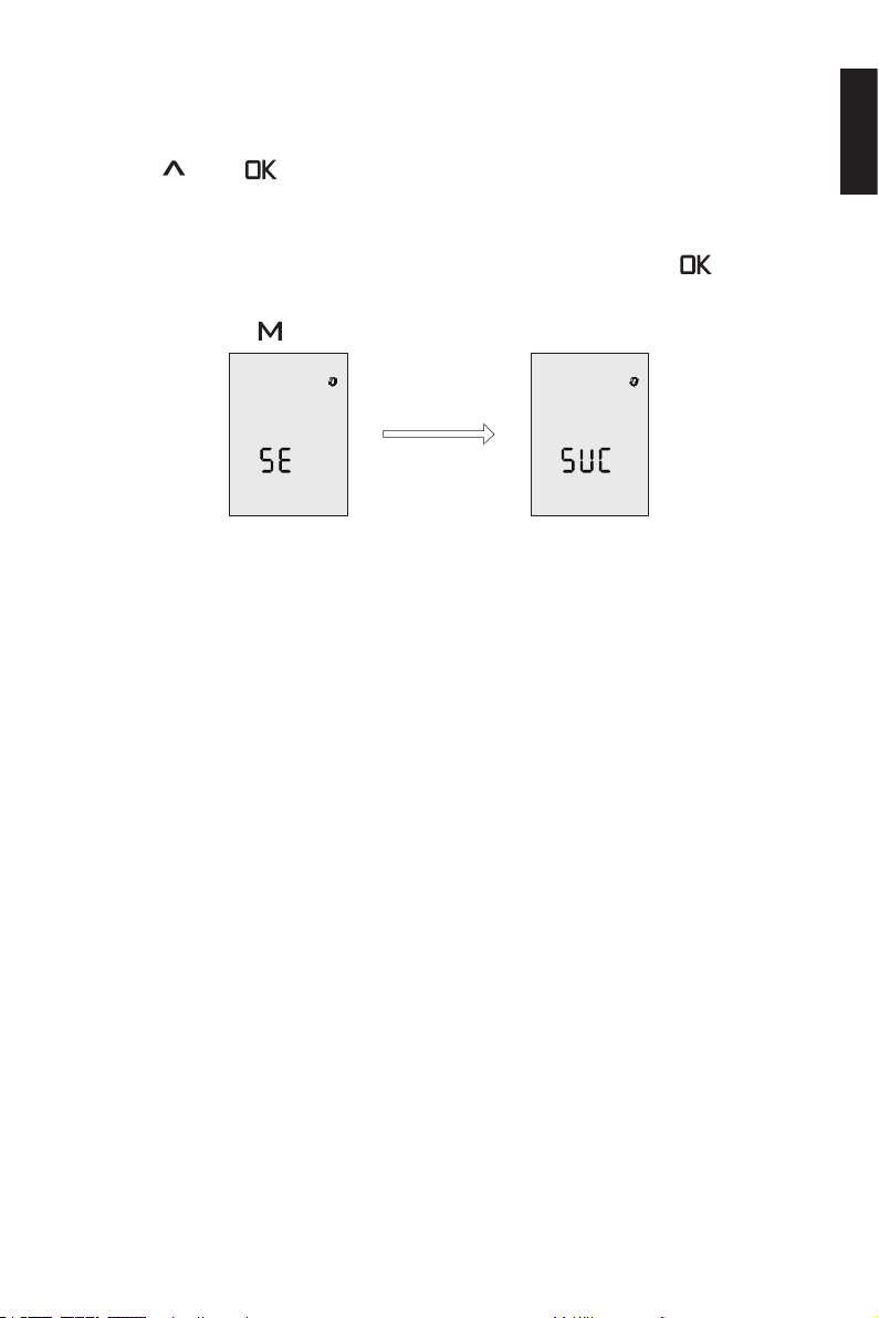
5.5 Use of Safety Wristband
5.5.1 Pairing Safety Wristband with Evo Control System
Press the “
icon and “SE”. At this time, approach the safety wristband that needs to be paired,
turn on the safety wristband, and the Evo control system displays the “SUC”, indicating successfully pairing. Keep in this interface and continue to press “ ” to pair the
safety wristband continuously (the maximum number of pairs is 8). After completing
the pairing, press the “ ” button to return to the main page.
5.5.2 Man Overboard Protection
After the safety wristband and the Evo control system are paired, when the safety
wristband falls into the water and the Evo control system is on, the outboard will stop
immediately. The Evo control system display will flash with a buzzing sound. The
safety wristband icon ashes and the number of safety wristbands decreases. At this
time, you can continue to operate the machine by returning the throttle to zero posi-
tion. The buzzer of the Evo control system will stop, but the display continues to ash.
If you conrm that you need to cancel the alarm state, please restart the Evo control
system or the disconnected wristband.
” and “ ” buttons and hold for a while to display the safety wristband
Figure 5-9
English
5.5.3 Emergency Stop
After the safety wristband and the Evo control system are paired, when the Evo control system is in operation, short press the button of the safety wristband, the out-
board will stop immediately. The display of the Evo control system will ash with a
buzzer. At the same time, the safety wristband icon ashes and the number of safety
wristbands displayed at the bottom decreases. At this time, you can continue to operate the machine by returning the throttle to zero position. The buzzer of the Evo con-
trol system stops, but the display continues to ash. If you conrm that you need to
cancel the alarm state, please restart the Evo control system or short press the safety
wristband after 5 seconds.
33
Page 36
When a wristband is disconnected or an emergency stop is performed, the stop
command of other wristbands will not work until it returns to the normal state.
5.6 Pairing Evo Control System with the Outboard
Before use please pair control system with the outboard. Evo Tiller will automatically
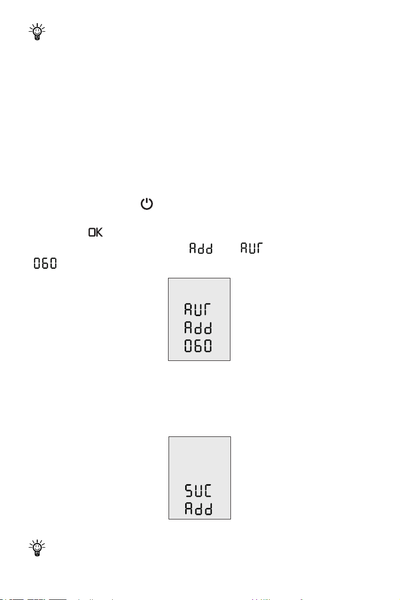
pair with the outboard after mounting on the outboard properly. There are two methods to pair the remote control with the outboard. Please choose one of the two methods and follow the steps to build new communication.
Method 1. Pairing without Communication Cable
Step1: Switch off system power and hold the remote control within 0.5m of the out-
board.
Step2: Press and hold the “ ” button to switch on the remote control.
Step3: Ensure the wireless indicator is shown constantly on the home page.
Step4: Press “ ” button and hold 5s to enter the pairing setting page (Figure 6-9).
On this page, you can nd the blinking “ ” and “ ” , and a countdown timer
“ ” (60s).
Figure 5-10
Step5: Switch on system power. Wait for them to get paired in seconds.
Step6: After pairing, the LCD panel will display as Figure 6-10 for 5s, then returning to
home page automatically.
Figure 5-11
If pairing fails within 60s, go back to Step4 and try again.
34
Page 37
Method 2. Pairing with Communication Cable
Step1: Switch off system power and the remote control.
Step2: Connect the remote control and the Communication module with a communi-
cation cable.
Step3: Switch on system power and the remote control. Wait for them to get paired in
seconds. Pairing succeeds when home page displays.
No matter it is in wireless communication status or not, it will switch to wired
communication status when you are pairing with a communication cable.
If the control system or the outboard is replaced with a new one, the original
wireless link will break and wireless communication failure will occur. The main
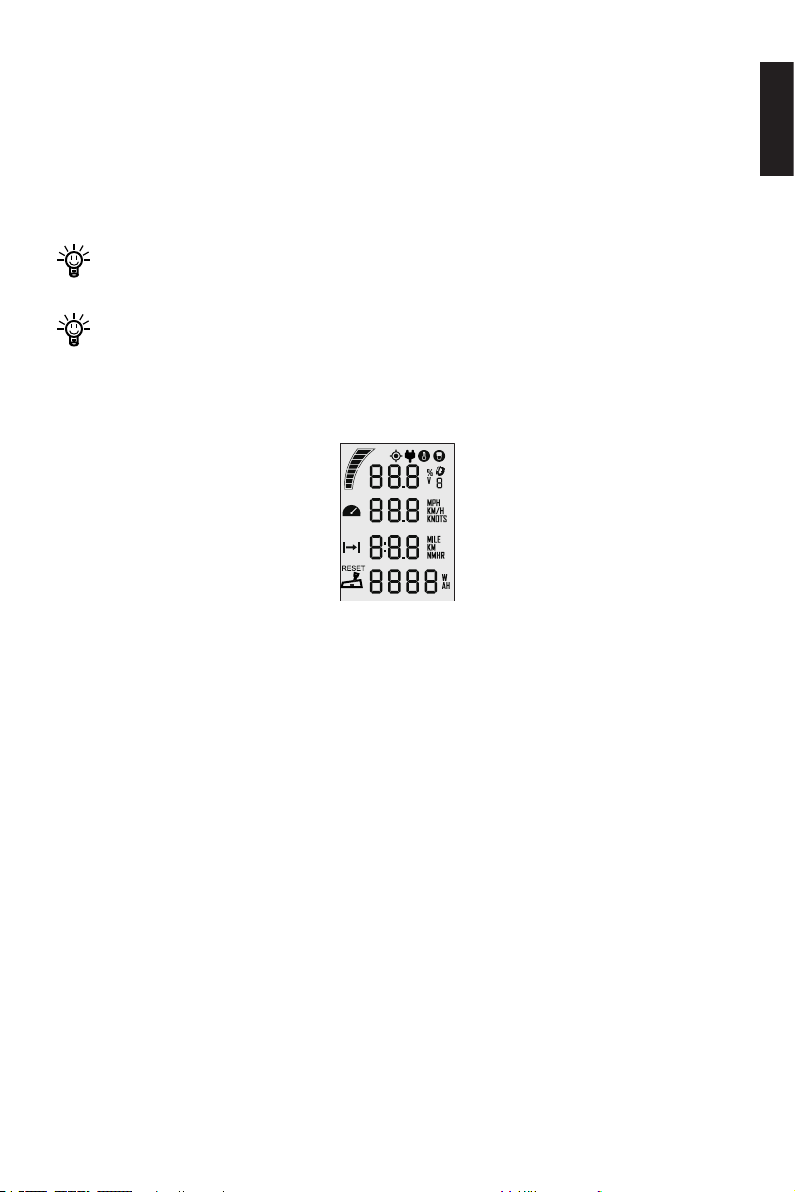
page of the LCD panel on the Control system will display as below. In this case,
users should conduct pairing again.
Figure 5-12
However, if the Control system and the outboard are not replaced, but the LCD
panel still displays like this, you should check and:
1) Make sure the Control system is not far from the outboard motor;
2) Make sure all the equipment involved is normally powered on.
If the Control system still displays like Figure 6-11 after check, it indicates an er-
ror has occurred. Please contact your dealer for repair.
English
35
Page 38
5.7 Hydro Generation Function
NAVY Evo outboard can drive the propeller to charge the battery (only the ePropul-
sion battery) through water ow.
The machine will enter the hydro generation state if the following conditions are
met:
1. The Evo control system is set to turn on the hydro generation function (enabled by
default).
2. The Evo control system is in the zero position.
3. The ePropulsion battery power is below 90%.
4. The machine will enter the hydro generation state after the boat speed is above
6km/h stable for 4 seconds.
5. The hydro generation function can be used only when connecting ePropulsion
batteries.
6. If using E-series battery, please connect with a communication cable.
When any of the following conditions occur, the hydro generation will be stopped:
1. The Evo control system is set to turn off the hydro generation function.
2. The Evo control system is in the forward / backward state (not in the zero
position).
3. The ship is not traveling or traveling too fast (NAVY 3.0 Evo is higher than 40km/
h or NAVY 6.0 Evo is high than 45km/h).
4. The battery level is higher than 90%.
Only when connecting with ePropulsion batteries, the hydrogeneration function
can be turned on.
Set up the hydro generation function
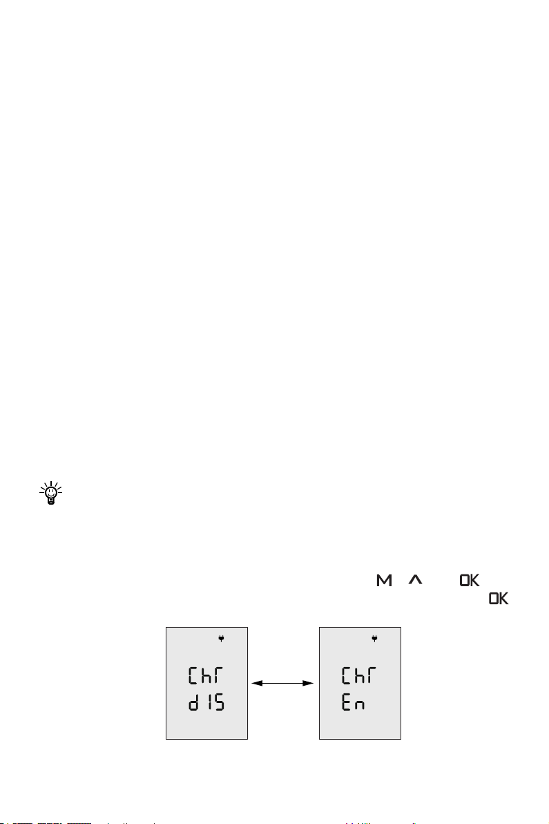
When the Evo control system and the machine are successfully connected, and the
Evo control system and the outboard are both on. Press the “ ”, “
tons at the same time to enter the hydro generation setting interface. Then press “
” to change the state of the hydro generation function (En means on, Dis means off).
Figure 5-13
36
” and “ ” but-
Page 39
5.8 Warning Messages
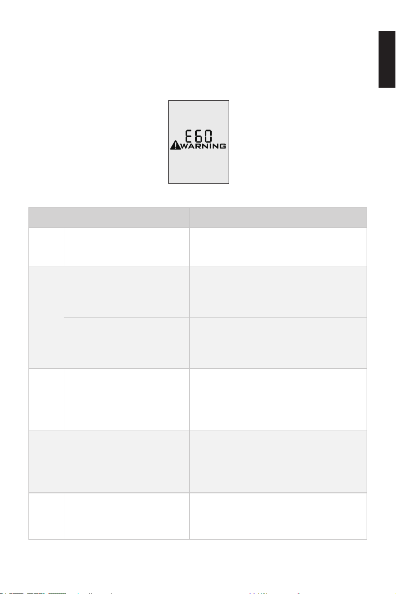
When the outboard motor is running in abnormal conditions or out of order, a warning
message with an error code will display on the LCD panel. Figure 6-13 is an example.
Please nd more error codes and corresponding solutions in the below table.
Figure 5-14
Code Cause Solution
English
Battery voltage beyond opera-
E01
tion range.
Propeller may be blocked,
causing motor overcurrent
E02
Motor fails or circuit board
fails causing motor overcurrent
The battery voltage level is
E06
too low.
Motor stall, which may be
E10
caused by blocked propeller
The temperature of motor is
E11
too high.
Replace a battery based on suggested
operation specications.
Refer to Solution to E10.
Try to turn off the main switch and wait for
10 seconds then turn on the switch again.
Operate the motor at low power. Please
charge the battery as soon as possible.
Turn off power, then clean up the things
winding around the propeller. Test if the
propeller can be rotated by hand before
operation.
Stop operating the outboard and wait until
the temperature falls within the normal
operating temperature range.
37
Page 40
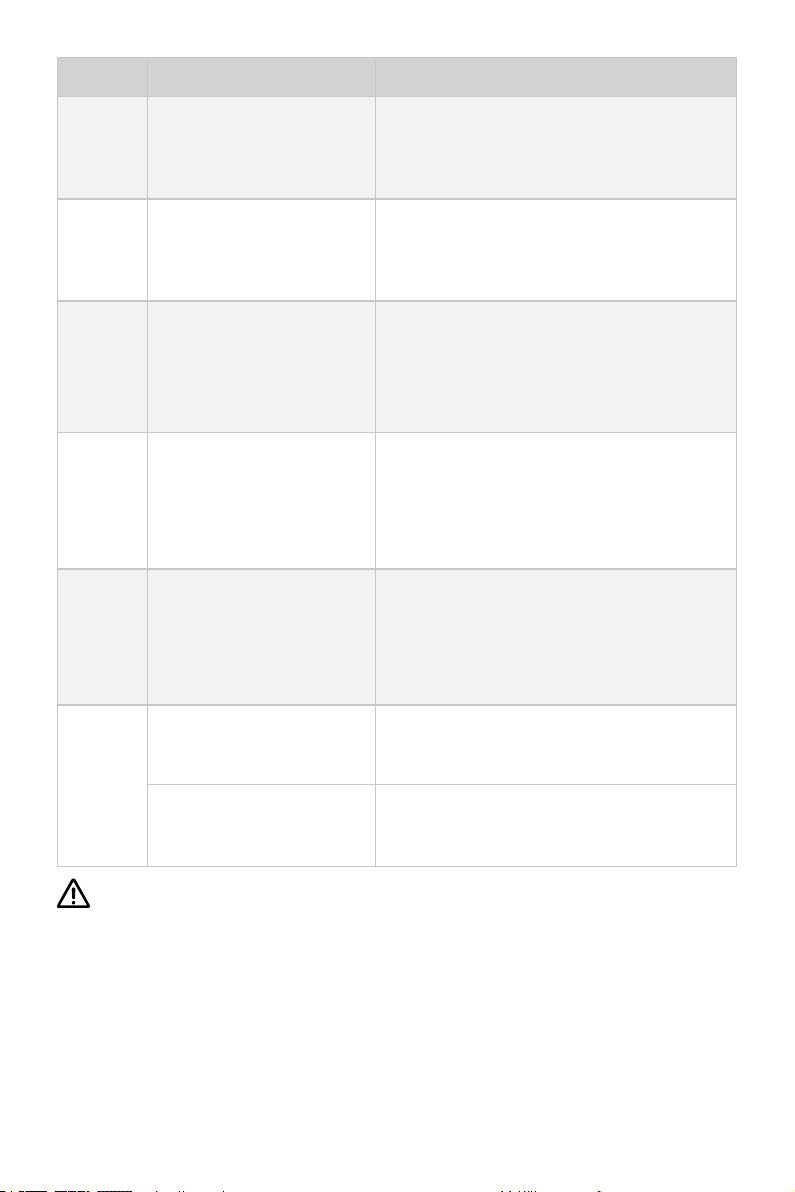
Code Cause Solution
E12
E22
E30
E56
E60
The temperature of circuit
board is too high.
MCU Communication Abnormality
Throttle position sensor
failure, should recalibrate
the throttle position sensor.
Communication Error between outboard and battery
The remote control is running out of power.
Stop operating the outboard and wait until
the temperature falls within the normal
operating temperature range.
Please restart to see if the error disappears,
if not, please contact your dear for help.
Please refer to section 6.3.2 Recalibration to
recalibrate the throttle position sensor.
Check if the communication cable between
outboard and battery is well connected, if
yes, please restart the system.
Please connect the remote control to the
outboard by a communication cable. Please refer to section 6.2.2 Charged by Wired
Connection.
All cha-
racters
display
The motor has no power.
Not paired
If the problem persists, please consult your ePropulsion authorized dealer for
assistance.
Connect the battery to the outboard and
then turn on the main switch.
Please refer to section 6.6 Pairing Control
System with the Outboard.
38
Page 41
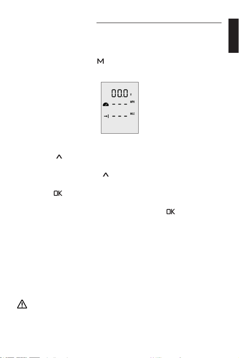
6 Configurations
6.1 Preference Settings
It’s advised to set display preference by these steps before operation.
Step1: In power-on state, press “ ” button and hold to enter the preference setting
page as shown in Figure 6-1. Users can choose display items based on personal
needs and preference.
Figure 6-1
Step2: On the preference setting page, the blinking item is the object waiting to be
set. Press the “
ure 6-1, if “ V ” is blinking on the preference setting page, it means that “ V ” has other
alternate options. Just press the “
displayed item is switched from voltage to battery level.
Step3: Press “ ” button to save setting for the current item and skip to the next
item simultaneously.
Step4: When all the items have been set well, long press the “ ” button to save all
the settings and return to the main page.
” button to view options for the blinking item. For example, in Fig-
” button, and “ V ” will switch to “ % ”, i.e. the
English
6.2 Battery Configuration
Accurate battery conguration helps achieve precise estimation of the battery's discharging state. When using an ePropulsion E Series Battery, battery conguration is
self-activated by the control system given that all the communication cables are well
connected. When not using E Series Batteries, users should manually congure the
batteries via Remote Control/Tiller at the rst time use, so the battery level will dis-
play more accurate.
Battery conguration should be carried out if a battery with different type/capacity/voltage is connected to NAVY 6.0 for the rst time.
39
Page 42
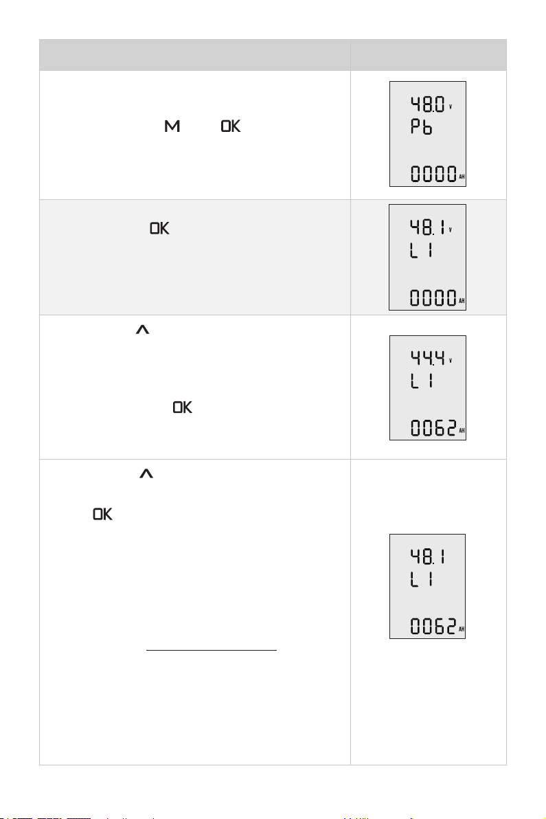
Battery Configuration Process LCD Displaying
Step1: First, turn on the main switch and the Evo
Remote Control / Evo Tiller.
Press and hold the “ ” and “ ” button
simultaneously to enter the battery setting page.
Users can see the attery type blinking and it’s ready
for configuration.
Step2: Pressing “ ” button to switch the battery
type options between Pb, Li and LFE.
Pb: Lead-acid battery Li: Lithium battery
LFE: Lithium-ion ferrous phosphate battery
Step3: Press “
setting and return to the top battery nominal voltage
setting item.
The voltage options are varied according to the
battery types. Press “ ” button to view the
options and select the closest nominal voltage
value according to the battery you use.
Step4: Press “
and skip to the below battery capacity setting item.
Press “ ” button to change the value and set the
battery capacity according to the battery you use.
Note that the unit of capacity is “Ah”, usually the
capacity of battery is expressed in “Wh”, and we can
get the capacity in “Ah” by following the below for-
mula:
Capacity in Wh
Capacity in Ah =
Nominal voltage in V
Eg. if users use a 3000Wh Lithium battery with
48.1V nominal voltage, then the battery is about
62.37Ah, so you can set 62Ah as the capacity setting.
” button to save battery type
” button to save battery voltage
40
Page 43
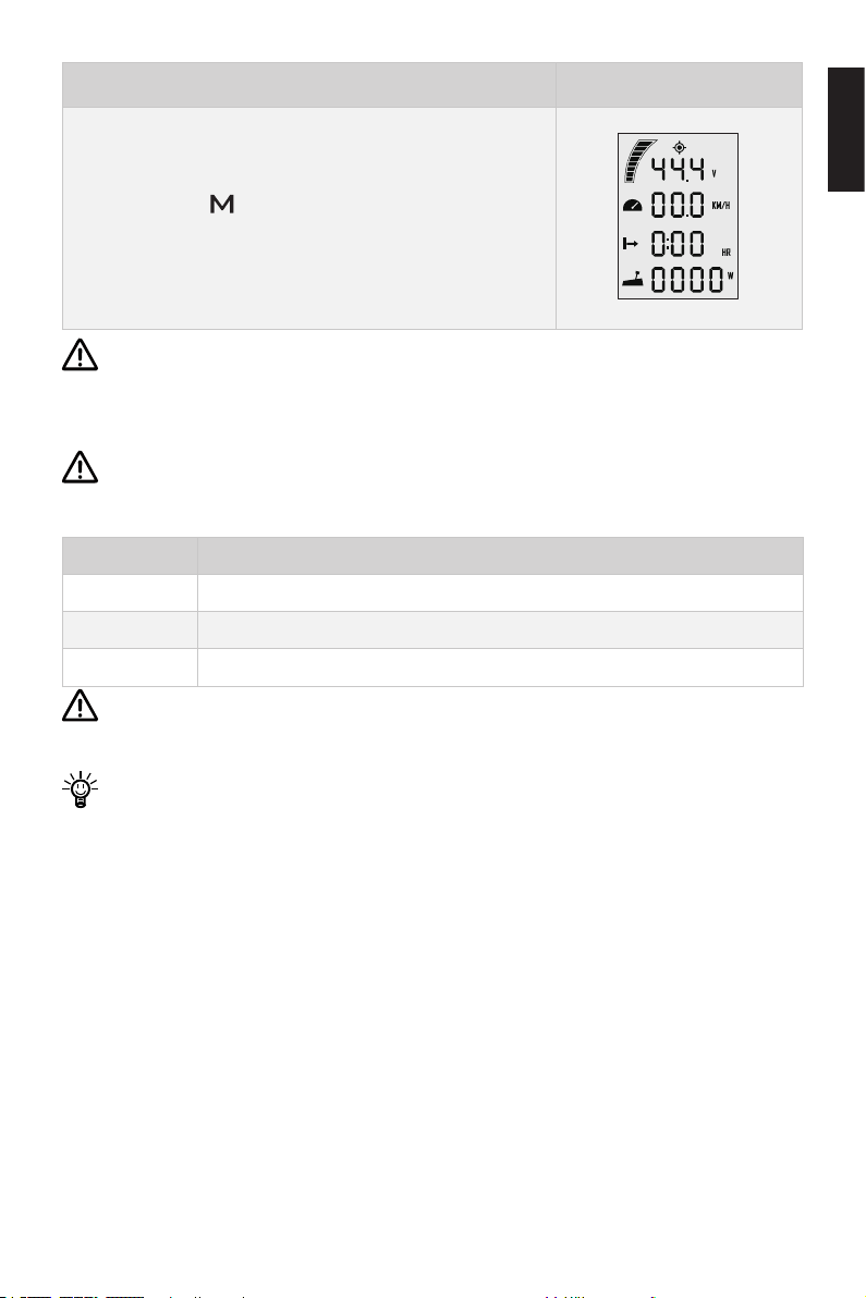
Battery Configuration Process LCD Displaying
Step5: Press “ ” button to save all the settings
and return to the main page.
Lithium batteries, lead acid batteries and lithium iron phosphate batteries are
recommended to use with NAVY Evo. Other types of battery may fail to make
NAVY Evo work properly.
When you use the below batteries, please set battery type and rated voltage value based on the parameters in the following table.
Battery type Nominal Voltage options
LI 43.2V 44.4V 45.6V 46.8V 48.1V 49.4V 50.4V 51.8V 53.2V
Pb 44.0V 46.0V 48.0V 50.0V 52.0V 54.0V
LFE 44.8V 48.0V 51.2V
Update the battery conguration is necessary if a different type of battery has
been applied.
English
When using non-ePropulsion batteries, before starting the outboard, users
should congure the batteries via the Evo Control System for the rst time use,
otherwise the batteries may not work properly.
41
Page 44

7 Checklist before Use
1. Ensure the propeller is correctly and firmly mounted on the outboard.
2. Ensure the outboard is correctly and firmly mounted on the boat.
3. Ensure the throttle and steering wheel are installed in proper position before
turning on the power.
4. Ensure the throttle travels smoothly with no obstacles.
5. Before connecting the battery, check and make sure there is no poor contacts or
defects in cables.
6. Check and ensure the main switch is able to power on and off normally. After that,
turn off the main switch.
7. Ensure the battery has enough power.
8. Ensure the Evo Remote Control has enough power when the Remote Control is
wirelessly connecting to the outboard.
Start the outboard only when the propeller is beneath water, as the rotating propeller is dangerous.
If the cable is immersed in water, please dry it completely before connecting it to
the battery or power on the system.
8 Starting the Outboard
1. Complete the check list.
2. Remove the kill switch from the Remote Control/Tiller.
3. Push/Turn the throttle to zero position.
4. Connect the battery to the outboard.
5. Fix the outboard with a proper trim angle.
6. Turn on the main switch. If the outboard is connected to an E Series Battery,
please also press the battery power button to power on.
7. Press “ ” button to turn on the Remote Control/Tiller and the main page will
display.
8. Carry out preference setting and battery configuration if necessary.
9. Tie the kill switch to your wrist or life vest, then attach the kill switch on the
Remote Control/Tiller.
10. Push/Turn the throttle slowly to start your outboard.
42
Page 45
9 Stopping the Outboard
Usually, it’s recommended to stop the outboard as the following procedures.
1. Return the throttle to zero position.
2. Wait until the outboard stops, then detach the kill switch from the Remote
Control/Tiller Handle.
3. Press and hold the “ ”button until the Remote Control/Tiller Handle is powered
off.
4. Turn off the main switch. If the outboard is connected to an E Series Battery,
please also press the battery power button to power off.
5. Tilt the outboard above water surface or detach it from boat.
If the outboard motor will not be used soon, it’s recommended to tilt the outboard out of water, otherwise erosion may occur.
The outboard will stop if one of the situations occurs.
1. The throttle is in zero position.
2. The kill switch is not in the correct position of Remote Control/Tiller Handle.
3. The main switch is off.
4. The communication between Remote Control/Tiller Handle and outboard
breaks.
5. The connection between battery and outboard breaks.
6. Failure exists in the control system (e.g. motor is blocked or the low battery
voltage level is detected).
English
43
Page 46
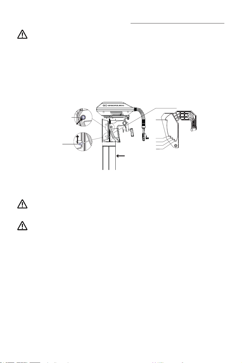
10 Trim Angle Adjusting
Only adjust the outboard trim angle when the outboard is stationary.
There are ve trim angle options including 60°,15°,10°,5° and 0°. Adjust the outboard
trim angle based on specic conditions. E.g. when the boat is in shallow water or the
outboard is not in use, tilt the outboard and adjust the trim angle to 60°. For normal
operation, x it to a proper trim angle where the shaft is vertically downward during
operation. Be reminded that the best trim angle varies by boat type, operation conditions, weather, etc.
Back Side
Release Button
Trim Lever
60°
15°
10°
5°
0°
Figure 10-1
Tilting up
Detach the Tiller rst before tilting the outboard motor up to the position with
max trim angle.
Do not use the tiller handle to tilt or lift your outboard. The tiller handle is not
designed to support the weight of the outboard, and damage may occur. Please
use the cowling to support the weight of the outboard while lifting and tilting.
Pull up the trim lever with one hand, and lift the outboard shaft with the other hand to
enlarge the trim angle to a particular degree. Then, release the trim lever to lock the
trim angle.
Tilting Down
The release button is raised when the trim angle is maximum at 60° position. Press
the release button and tilt up the propeller shaft slightly to about 80° position, then lay
it down, and the outboard shaft will return to 0° position.
44
Page 47
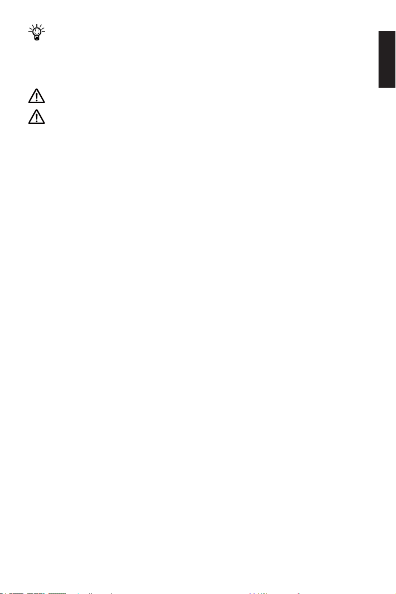
It’s suggested to test with different trim angles to nd the optimal trim angle for
the boat and operation. Note that the speed should be increased gradually dur-
ing the test, and check if there are any abnormal situations. Stop the outboard
and decrease the trim angle if necessary.
Slight and gentle operations are recommended when tilting up and down.
The trim lever is only used to increase the trim angle from 0° to 60°. If users
want to decrease the trim angle, eg. from 15° to 5°, follow these steps: rst, tilt
the outboard shaft to the maximum angle (60°); then, press the release button to
return the outboard shaft to the 0° position; last, use the trim lever to tilt up the
shaft to the 5° position.
English
45
Page 48
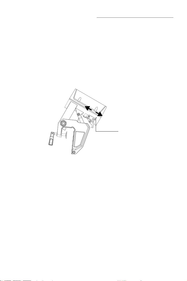
11 Anti-grounding Mode
When the boat runs in shallow water or in complicated underwater conditions, it may
meet grounding dangers. Setting the outboard to anti-grounding mode will protect
the outboard motor from damage if the outboard hits submerged reefs or rocks. In
anti-grounding mode, the underwater part of the outboard is exible in tilting direction
and the motor will automatically tilt up if it hits something underwater.
Step 1: Use the left hand to pull the gear hook to turn it through a certain angle to ensure that the beach structure wrench can be pulled down to the end of the stroke.
Step 2: Use your right hand to pull down the beach structure wrench to the end of the
stroke (pull up to exit the beach).
Inactivate the
anti-grounding mode
Set the outboard in
anti-grounding mode
Beaching Lever
46
Page 49
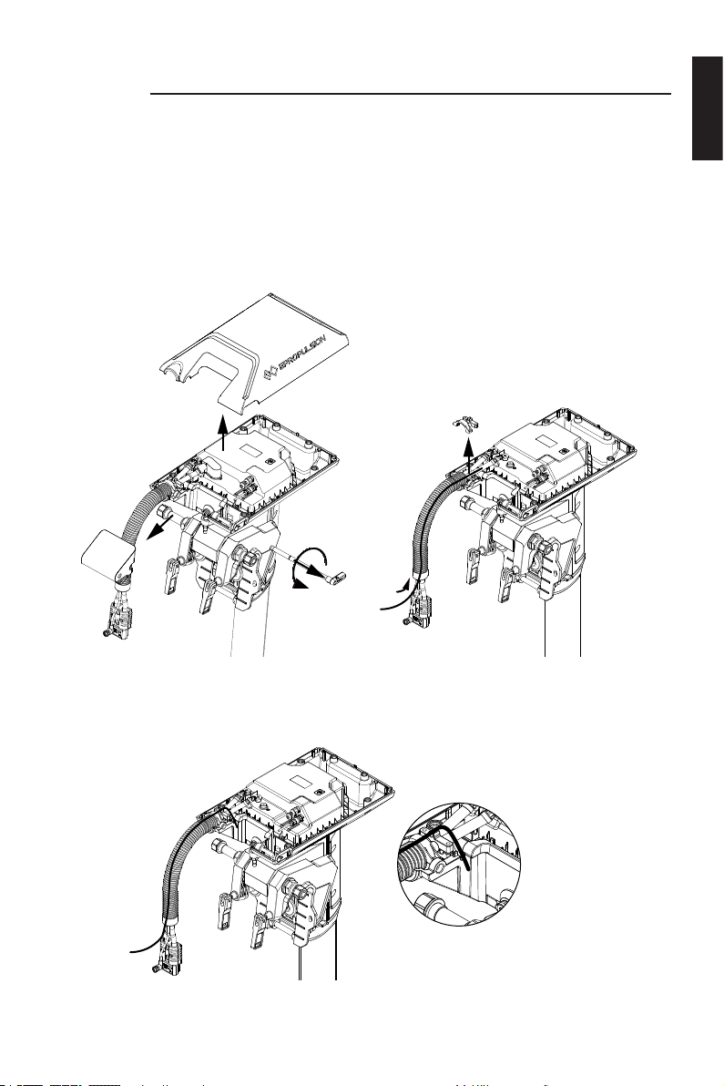
12 Thread the communication cable into the bellow
In order to protect the cable and the beauty of the machine, it is recommended that
when using a 5m communication cable, follow the following operations to thread the
communication cable into the bellow:
Step 1: Remove the handle shaft, the decorative cover and the upper case, remove the
card holder, and thread the cable through the bellow (it is recommended to insert the
hard line into the bellow rst to help thread the communication cable).
English
Figure 12-1
Step 2: Put the cable into the card wire slot, and then put it into the cable hole of the
lower case.
Figure 12-2
47
Page 50
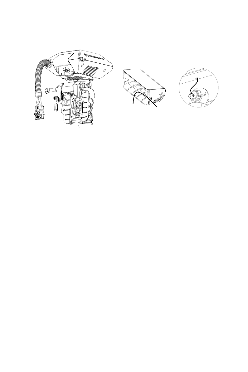
Step 3: Install the upper case, and then install the decorative cover, thread through
the two cable holes as shown in the gure, and nally connect to the communication
port.
Figure 12-3
48
Page 51
13 Maintenance
13.1 Notes
Regular maintenance is benecial to keep your outboard working in optimal condition.
Do not start the outboard in shallow or unknown water conditions. Only use the outboard in deep water area.
In order to clean and reduce corrosion, use fresh water to wash the whole outboard
after use in salt water.
Disconnect the battery from outboard before maintenance.
Conduct the maintenance under instructions of professional experts or your
dealer.
Only use ePropulsion original components for replacement and maintenance.
13.2 Maintenance Time Table
Regularly maintained in proper manner and used in normal condition, the outboard
can work at its optimal state. The following table shows a general maintenance frequency, which however may vary according to operating conditions.
English
Initial Every
Item Operations
Anode Check/Replace
Propeller
and pin
The “□” symbol indicates checks may be carried out by users. The “■” symbol
indicates work to be carried out by your dealer.
Check/Replace
50 hours
(3 months)
□ □ ■
□ □ ■
49
100 hours
(6 months)
200 hours
(12 months)
Page 52
13.3 Propeller Maintenance
Disconnect the battery with outboard before maintenance.
Gloves are recommended to protect your hand from sharp propeller edges.
Check the propeller according to the following instructions, then refer to then refer to
section 2.2 Selecting and Mounting the Propeller to replace a new propeller if necessary.
1. Check the propeller blades for wear, cavitation erosion and other damage.
2. Check the pin for wear and damage.
3. Check for water plants, fishing net or line twine around the propeller.
4. Replace a new anode if necessary.
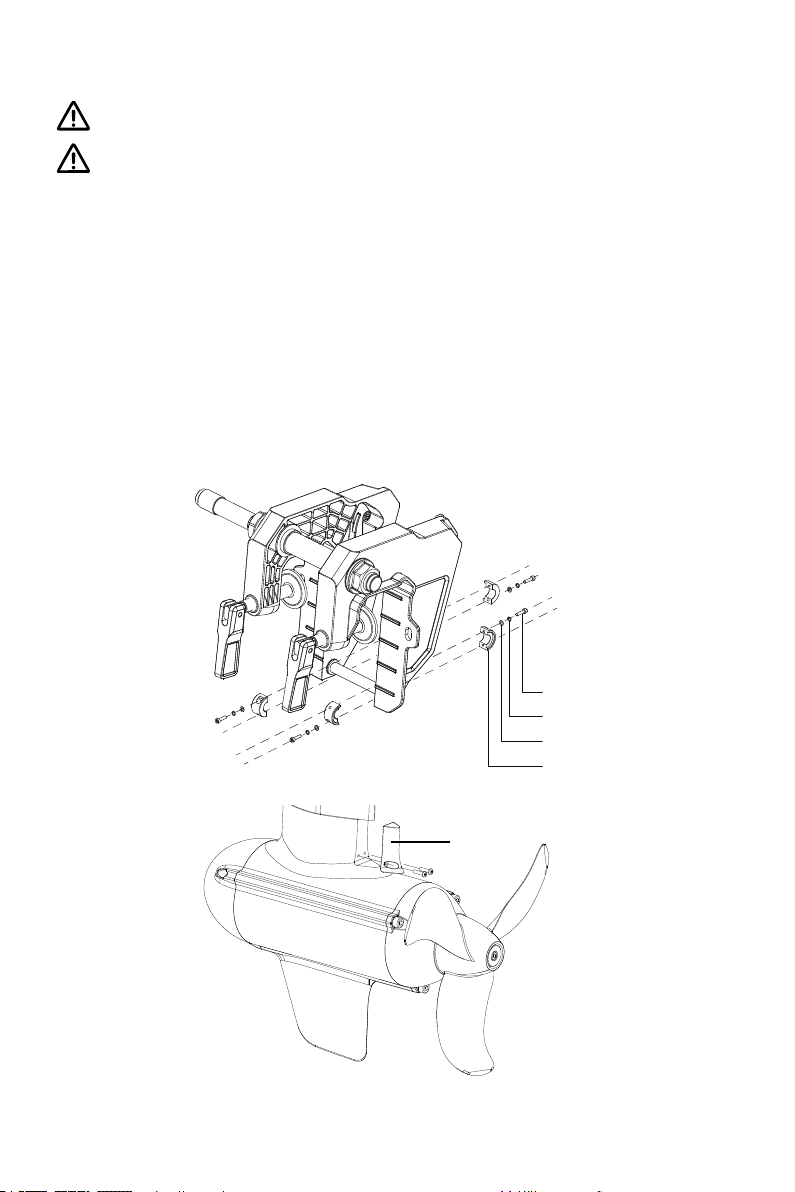
13.4 Replacing the Anode
Please refer to the gure below to replace a new anode if necessary.
Figure 13-1
Figure 13-2
50
Screw
Spring Washer
Plain Washer
Anode
Anode
Page 53
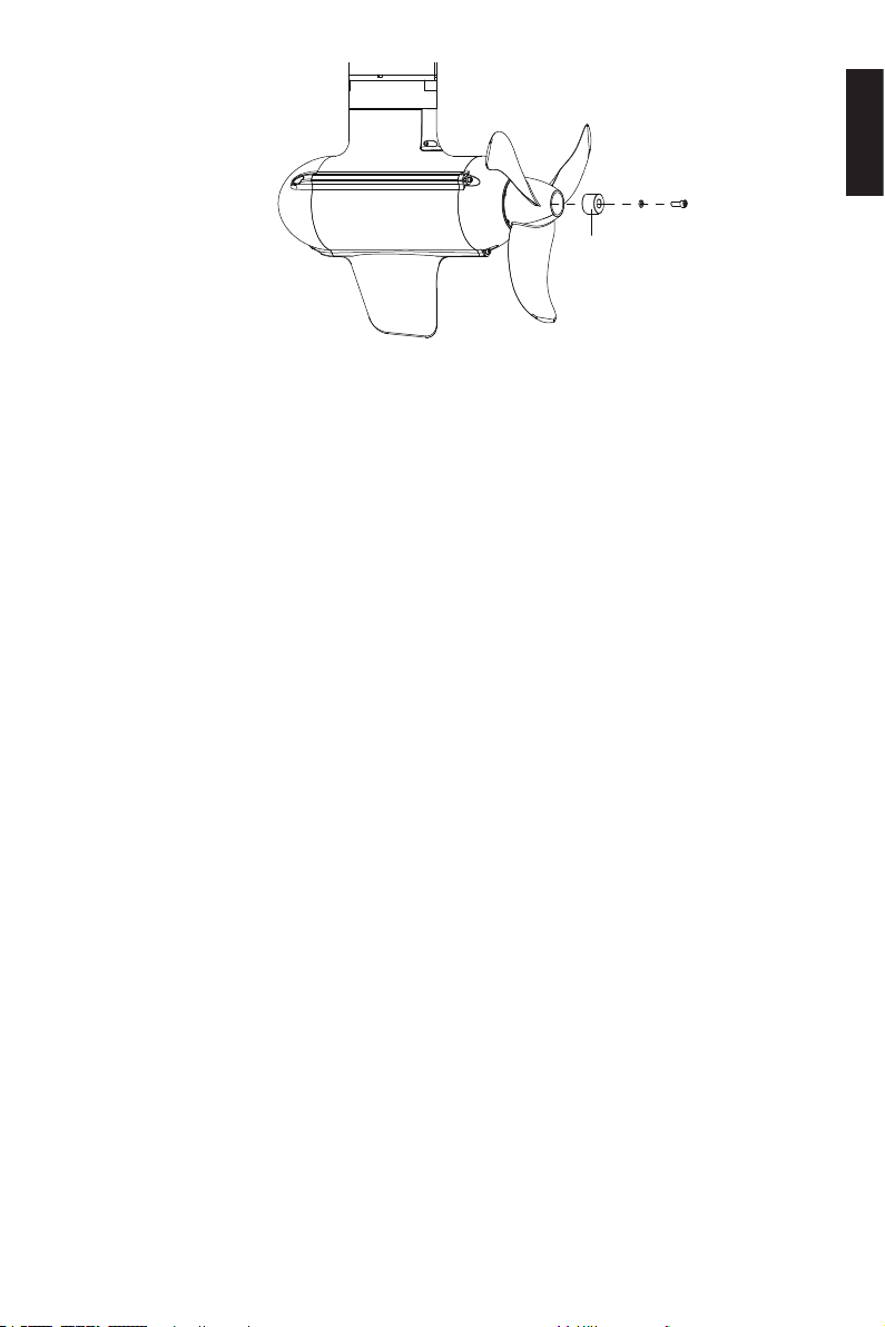
Figure 13-3
English
Anode
51
Page 54
14 Transportation and Storage
14.1 Transport
For long distance transport, please use the ePropulsion original packing materials to
pack the outboard before delivery.
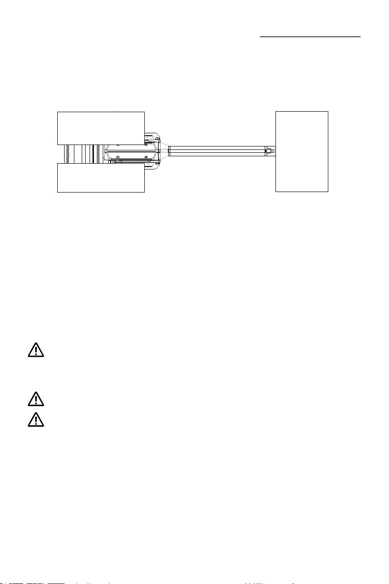
Figure 14-1
14.2 Placement
When placing the outboard on a surface, ensure the surface is at and horizontal. It’s
better to put some damping cushion underneath.
14.3 Storage
If you are not using the outboard motor for more than 2 months, it’s advised to contact your dealer to clean and check the outboard prior to storage. It’s recommended
to pack the outboard with ePropulsion original packing materials for storage.
Get adequate damping protection measures before transport and storage. And
ensure the propeller receives no pressure if the propeller is mounted on the pro-
peller shaft.
Store the outboard in a well-ventilated and dry area without direct sunshine.
Ensure the ambient temperature is proper (-25°C~50°C) during storage.
52
Page 55

15 Emergency Situations
15.1 Collision
If the outboard strikes some object beneath the water, please follow below procedures.
1. Stop the outboard immediately and then turn off the main switch.
2. Check the mechanical structure to see if there are damages.
3. Return to the nearest harbor or pier in low power.
4. Call your dealer to check the outboard.
15.2 Sodden Outboard
If the outboard is sodden, stop it immediately and turn off the main switch then disconnect the battery. Bring the outboard to the dealer. And ensure the outboard is thoroughly inspected before operating it again.
15.3 Low Battery Level
When the battery voltage is lower than 42V, the throttle power will be limited gradually
along with the voltage drop. When the battery voltage drops below 39V, the outboard
will stop automatically to prevent battery over-discharge. If this happens when the
outboard is far away from the shore, and there is an alternative battery, it’s recommended to wait until the battery voltage recovered to 42V or above. You can restart
the outboard with throttle power below 1000W.
English
15.4 Over-temperature Protection
When the operating temperature is high, the max input power will be limited within
rated power, and the power will decrease with the rise of temperature. If the system
temperature keeps rising and surpasses a threshold, the outboard motor will shut
down automatically to avoid over-temperature. Users should stop operating the outboard and wait until the temperature falls within the normal range.
53
Page 56
16 Warranty
The ePropulsion limited warranty is provided for the rst end purchaser of an ePropulsion product. Consumers are entitled to a free repair or replacement of defective
parts or parts which do not conform with the sales contract. This warranty operates
in addition to your statutory rights under your local consumer law.
16.1 Warranty Policies
ePropulsion warrants its products to be free of defects in material and workmanship
for a limited period since the date of purchase. Once a fault is discovered, the user
has the right to make a warranty claim under the ePropulsion warranty policies.
Product Warranty Expiry Date
NAVY 3.0 Evo
NAVY 6.0 Evo
Components
have been
repaired or replaced
In order to validate the warranty, users are required to ll in the Warranty Card in
the package in advance.
Keep the product label in intact state and record the serial number on the label.
Never tear the label off the product. An ePropulsion product without the original
product label will not be applicable to warranty services provided by ePropulsion.
The warranty is valid only when the information is correct and complete.
Two years after the date of purchase (uncommercial).
Three months since the date of maintenance.
Note:
1. If the three-month period overlaps with the original
warranty period, the warranty against these
replaced or repaired parts still expires two years
after the date of purchase.
2. If the three-month period exceeds the original
warranty period, the repaired or replaced parts
continue applying to warranty during the extended
period.
Free warranty is only validated upon the presentation of legal serial number, Warranty Card, and evidence of purchase from an authorized ePropulsion dealer.
54
Page 57

Valid date of purchase should be established by the rst-hand purchaser with
original sales slip.
Free warranty is not transferable and will not be reissued.
Within the limits of the applicable laws, the warranty policies of ePropulsion may
update without prior notice. The latest version is available at our website www.
epropulsion.com.
16.2 Out of Warranty
Make sure the product is properly packed during delivery, the original ePropulsion
package is recommended. If the product got further damaged due to improper packing during delivery, the furtherly damaged part will be deemed as out of warranty coverage.
In addition, faults or damages caused by the following reasons are also excluded
from warranty scope within the covered period:
• Any improper operation contradicts the user manual.
• Accident, misuse, wishful abuse, physical damage overcharging, liquid damage or
unauthorized repair.
• Dropping, improper care or storage.
You should be noted that minor faults like normal wear and tear that pose no
influence on the intended function of the product are also not covered by the
warranty.
English
Consumables are out of warranty scope.
16.3 Warranty Claim Procedures
If you nd your product defective, you can make a claim to your dealer following below procedures:
1. Fill in the Warranty Card correctly and completely in advance. Then make your
warranty claim by sending it to your authorized ePropulsion service partner
together with valid proof of purchase. Usually these documents are required
when making a warranty claim: the Warranty Card, ex-factory serial number, and
evidence of purchase.
55
Page 58

2. Send the defective product to your authorized ePropulsion service point after
getting the confirmation. Note that the label should be kept intact. You can
also deliver the product to your authorized ePropulsion dealer after getting
confirmation.
3. The defective components or parts will be either repaired or replaced according
to the diagnosis made by the ePropulsion authorized service partner.
4. If your warranty claim is accepted, the equipment will be repaired or replaced free
of charge. Note that any delivery cost incurred in the process is at your charge.
5. After careful examination and confirmation by ePropulsion authorized dealer, the
defective or faulty components will be repaired or replaced with brand new ones
against the actual condition.
6. In case your warranty claim be rejected, an estimated repair charge with round
trip delivery cost will be sent for confirmation. ePropulsion authorized service
point will conduct maintenance accordingly only after your confirmation.
If warranty expires, you can still enjoy maintenance services from authorized
ePropulsion service partners with minimum maintenance charge.
56
Page 59

Einleitung
Für Ihren Kauf von sowie Ihr Vertrauen in ePropulsion Produkte und unser Unternehmen bedanken wir uns herzlich. Wir haben uns zum Ziel gesetzt, umweltfreundliche,
sichere und zuverlässige elektrische Außenborder und Bootsantriebe herzustellen.
Für weitere Informationen besuchen Sie unsere Website: www.epropulsion.com.
Über diese Bedienungsanleitung
Vor der Verwendung des Produkts lesen Sie bitte sorgfältig diese Bedienungsanleitung (nachfolgend „Handbuch“ genannt), um eine ordnungsgemäße und sichere Bedienung zu gewährleisten. Mit der Verwendung dieses Produkts erklärt der Benutzer,
dieses Handbuch vollständig gelesen und verstanden zu haben. Vor der Inbetriebnahme lesen Sie bitte sorgfältig dieses Handbuch und machen Sie sich mit den Funktionen und Eigenschaften des elektrischen Außenborders vertraut. Den Außenborder
niemals an Personen verleihen, die sich mit der Bedienung nicht auskennen. ePropulsion übernimmt keine Verantwortung für Personen- und Sachschäden, die durch
Nichtbeachtung des Handbuchs entstehen.
Zur Verbesserung unserer Produkte behalten wir uns das Recht vor, Inhalte dieses
Handbuchs zu ändern. Ebenfalls gehören alle geistigen Eigentumsrechte, einschließlich (jedoch nicht beschränkt auf) aller Urheberrechte, Patente, Markenzeichen und
Designs ausschließlich der Fa. ePropulsion.
Dieses Handbuch unterliegt unregelmäßigen Änderungen. Für die aktuelle Version
besuchen Sie bitte unsere Website: www.epropulsion.com. Falls Sie Abweichungen
zwischen Ihrem Produkt und den Beschreibungen dieses Handbuchs feststellen oder
Fragen zum Produkt oder Handbuch haben, besuchen Sie bitte unsere Website www.
epropulsion.com oder nehmen Sie Kontakt mit uns auf. Das alleinige Recht für die Er-
klärung zum Inhalt dieses Handbuchs ist ePropulsion vorbehalten. Dieses Handbuch
ist in verschiedenen Sprachen vorhanden. Bei Abweichungen dient die englische Ver-
sion als Orientierung.
Deutsch
Symbole
Beim Lesen dieses Handbuchs beachten Sie bitte die folgenden Symbole:
Wichtige Hinweise und Warnungen
Nützliche Informationen zum Gebrauch
57
Page 60
Produktkennzeichnung
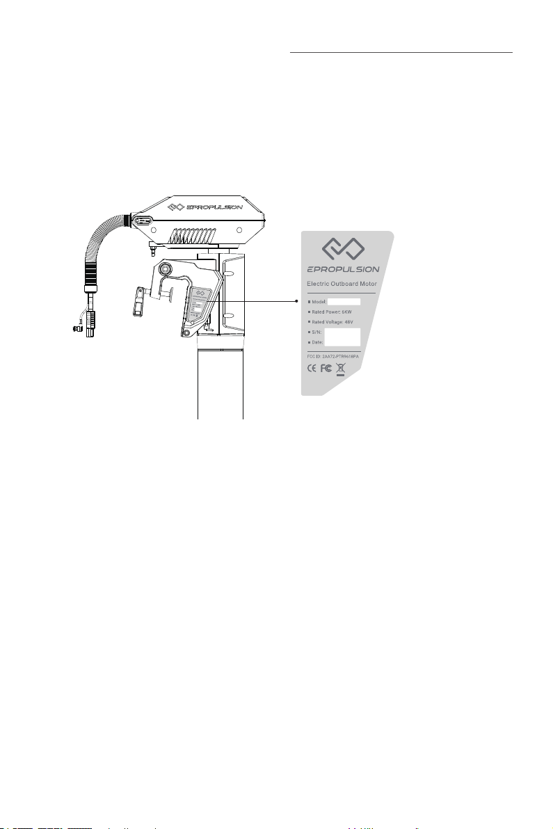
Die Seriennummer des Produkts dient als Nachweis bei der Inanspruchnahme der
Garantie- und Reparaturservices. Die Position der Seriennummern der Außenborder-Modelle Navy 6.0 Evo und Navy 3.0 Evo entnehmen Sie der folgenden Abbildung.
Bitte notieren Sie diese Nummern und bewahren Sie sie auf. Das Typenschild darf auf
keinen Fall entfernt werden, da die Garantie des Produkts sonst erlischt.
Abb. 0-1
58
Page 61

Inhaltsverzeichnis
Einleitung ................................................................................................ 57
Über diese Bedienungsanleitung ............................................................. 57
Symbole .................................................................................................. 57
Produktkennzeichnung ............................................................................ 58
1 Produktübersicht .................................................................................. 62
1.1 Lieferumfang ......................................................................................... 62
1.2 Bauteile und Bezeichnungen ................................................................ 65
1.3 Technische Daten .................................................................................. 66
1.4 Wichtige Hinweise ................................................................................. 67
1.5 Konformitätserklärung .......................................................................... 68
2 Vorbereitung der Batterie und des Propellers ........................................ 69
2.1 Auswahl der Batterie ............................................................................. 69
2.2 Einbau des Propellers ........................................................................... 70
3 Einbau des Außenborders ..................................................................... 72
3.1 Einbauposition ....................................................................................... 72
3.2 Einbau des Außenborders .....................................................................73
3.3 Einbau der Lenkung ............................................................................... 74
3.4 Einbau der Evo Pinne .............................................................................74
Deutsch
4 Anschluss der Batterie .......................................................................... 76
4.1 Anschluss einer 48-V-Batterie ..............................................................76
4.2 Anschluss der E-Serie-Batterien ........................................................... 77
4.3 Reihen-/Parallelschaltung der Batterien .............................................. 78
5 Evo Fernsteuerung / Evo Pinne .............................................................80
5.1 LCD-Display ............................................................................................ 80
5.2 Laden ...................................................................................................... 85
5.2.1 Laden über Solarenergie (empfohlen) ........................................ 85
5.2.2 Laden über Ladekabel ................................................................. 85
5.3 Leistungseinstellung ............................................................................. 87
5.3.1 Leistung einstellen ....................................................................... 87
5.3.2 Kalibrieren .................................................................................... 88
59
Page 62

5.4 Reißleinenschalter einsetzen ................................................................89
5.5 Sicherheitsarmband einsetzen ............................................................. 90
5.5.1 Registrierung des Sicherheitsarmbands mit der Evo
Fernsteuerung / Evo Pinne (Kopplung) ................................................ 90
5.5.2 Mann-über-Bord-Schutz ............................................................... 90
5.5.3 Not-Aus ......................................................................................... 90
5.6 Registrierung der Evo Fernsteuerung im Außenborder (Kopplung) ...91
5.7 Rekuperation ..........................................................................................94
5.8 Warnmeldungen .................................................................................... 95
6 Konfiguration ........................................................................................ 98
6.1 Benutzerdefinierte Einstellungen ......................................................... 98
6.2 Batteriekonfiguration ............................................................................99
7 Kontrolle vor dem Betrieb ................................................................... 102
8. Außenborder starten ......................................................................... 103
9 Außenborder stoppen ......................................................................... 104
10 Trimmwinkel-Einstellung .................................................................. 105
11 Bodenschutzmodus .......................................................................... 107
12 Verbindungskabel durch den Faltenbalg führen ................................ 108
13 Wartung ............................................................................................ 110
13.1 Wichtige Hinweise .............................................................................110
13.2 Wartungsplan ....................................................................................110
13.3 Wartung des Propellers ....................................................................111
13.4 Anode ersetzen .................................................................................111
14 Transport und Lagerung .................................................................... 113
14.1 Transport............................................................................................113
14.2 Aufstellen ........................................................................................... 113
14.3 Lagerung ............................................................................................ 113
15 Notfall-Maßnahmen ......................................................................... 114
15.1 Zusammenstöße unter Wasser ........................................................ 114
15.2 Ins Wasser fallen ............................................................................... 114
15.3 Batterie-Unterspannung .................................................................... 114
15.4 Übertemperatur ................................................................................. 114
60
Page 63

16 Gewährleistung................................................................................. 115
16.1 Garantiebedingungen ........................................................................ 115
16.2 Von der Garantie ausgenommen .....................................................116
16.3 Abwicklung eines Garantiefalls ........................................................ 116
Deutsch
61
Page 64
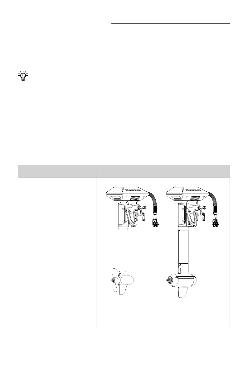
1 Produktübersicht
Der Navy 6.0 Evo ist ein elektrischer Außenbordmotor mit einer Leistungsaufnahme
von 6 kW. Der elektrische Außenbordmotor Navy 3.0 Evo hat eine Leistungsaufnahme
von 3 kW. Beide Geräte können sowohl mit der Evo Fernsteuerung als auch mit der
Evo Pinne angesteuert werden.
Um diesen Außenborder zu bedienen, benötigen Sie eine Evo Pinne oder eine Evo
Fernsteuerung, die nicht im Lieferumfang des Navy Evo Außenborders enthalten
sind. Von einem Vertragshändler der Fa. ePropulsion können Sie diese Geräte
erwerben.
1.1 Lieferumfang
Nach dem Öffnen der Verpackung überprüfen Sie bitte das Gerät auf mögliche Transportschäden. Bitte überprüfen Sie weiterhin die Vollständigkeit des Lieferumfangs
anhand der folgenden Liste. Bei Transportschäden oder fehlenden Teilen nehmen Sie
bitte Kontakt mit Ihrem zuständigen Vertragshändler auf.
Bezeichnung Anzahl Beschreibung
Außenborder 1 Stück
NAVY 3.0 Evo NAVY 6.0 Evo
62
Page 65
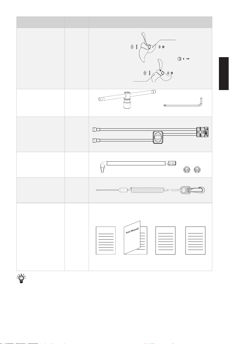
Bezeichnung Anzahl Beschreibung
Propeller mit einer
kleineren Steigung
Propeller mit einer
größeren Steigung
Propeller
(Standard-Zubehör
2 Satz
des Navy 6.0 Evo)
Schlüssel 1 Satz
19-mm-Schlüssel M6-Schlüssel
Deutsch
Netzkabel Hauptschalter
1 Stück
Winkelstange 1 Satz
Trageband Pinnenachse
1 Stück
Handbuch, Garantiekarte, Qualitäts-
zertikat für den
Außenborder und
Warranty
1 Satz
Fixing Guide Quick Start
Einladungskarte
für die Außenborder-Community
Um diesen Außenborder zu betreiben, benötigen Sie auch andere Zubehörteile
wie die Evo Steuerung, eine Batterie, ein Ladegerät und Verbindungskabel. Benutzer können bei Vertragshändlern der Fa. ePropulsion Original-Zubehör erwerben, wie zum Beispiel Evo Fernsteuerungen, Evo Pinnen, E-Serie-Batterien sowie
Ladegeräte und Verbindungskabel.
63
Page 66

Achten Sie darauf, dass der Propeller des Modells Navy 3.0 Evo bei der Lieferung
ab Werk bereits eingebaut ist. Im Lieferumfang des Navy 6.0 Evo sind zwei Propellergrößen enthalten. Der eine Propeller hat eine größere Steigung (schnell lau-
fend): Durchmesser 320 mm, Schaufelabstand 10,8 Inch und der andere hat eine
kleinere Steigung (langsam laufend): Durchmesser 340 mm, Schaufelabstand
8,5 Inch.
Für eine ordnungsgemäße Lagerung des Außenborders bewahren Sie bitte die
Original-Verpackung auf.
64
Page 67
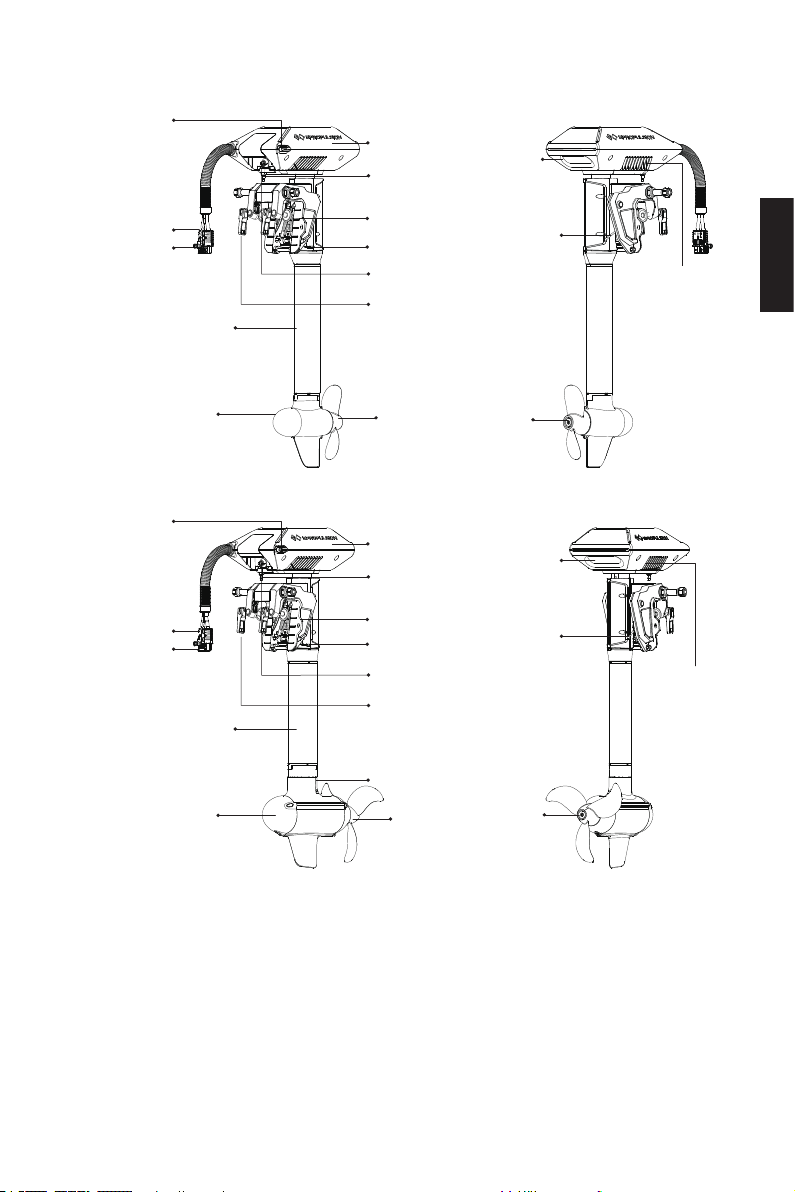
1.2 Bauteile und Bezeichnungen
Verbindungskabel
Pinnenachse
Pinnenachse
Verbindungskabel
Anschluss des
Netzkabels
Motorschaft
Anschluss des
Netzkabels
Motorschaft
Motor
Gehäuse
Einbauposition
Winkelstange
Halterung
Einstellhebel
Verbindungsanschluss
Klemmhebel
Halterungsgriff
Propeller
Abb. 1-1 Navy 3.0 Evo
Gehäuse
Einbauposition
Winkelstange
Halterung
Einstellhebel
Verbindungsanschluss
Klemmhebel
Halterungsgriff
Trimmhebel
Ventilator
Deutsch
Anode
Trimmhebel
Ventilator
Motor
Anode
Propeller
Abb. 1-2 Navy 6.0 Evo
65
Anode
Page 68
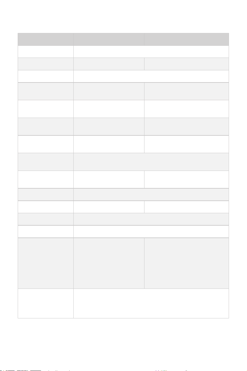
1.3 Technische Daten
Navy 3.0 Evo-S/L Navy 6.0 Evo-S/L
Typ Elektrischer Außenborder
Leistungsaufnahme 3 kW 6 kW
Nennspannung 48 V
Eingangsspannungsbereich
Äquivalente Antriebsleistung
Max. Gesamtleistung
Nenndrehzahl (vorwärts)
Kompatible Steuerungen
Abmessungen (L x T
x H)
Schaftlänge 634 mm (S) / 759 mm (L)
39 V – 60 V DC 39 V – 60 V DC
6 PS 9,9 PS
51 % 57 %
2300 1/min 1500 1/min
Evo Fernsteuerung / Evo Pinne / Evo seitliche Fernsteuerung
/ Evo Doppel-Fernsteuerung
437 x 314 x 1049 (S) /
1174 (L) (mm)
547 x 314 x 1087 (S) / 1212 (L)
(mm)
Nettogewicht 24,3 kg (S) / 25,1 kg (L) 36 kg (S) / 36,8 kg (L)
Trimmwinkel Manuell in 4 Schritten: 0°, 5°, 10°, 15°
Tiltwinkel manuell: 60°
12,6″ × 10,8″ drei Schaufeln aus
CFK / 13,4″ × 8,5″ drei Schaufeln
aus CFK
12,6″ × 8,7″ drei Schaufeln aus
Metall (optional)
-10°C – 45°C
Propeller
Umgebungstemperatur bei Betrieb/Lagerung
10,2″ × 6,7″ zwei Schaufeln
aus CFK
66
Page 69

1.4 Wichtige Hinweise
1. Vor jeder Fahrt den Zustand des Außenborders und den Batteriestand kontrollieren.
2. Die angezeigten Distanzen und Geschwindigkeiten werden durch GPS bestimmt.
Bei schwachem oder durch äußerliche Faktoren (Strömungen, Wind usw.) gestörtem GPS-Empfang können Abweichungen entstehen.
3. Den Außenborder nicht von oben bedecken, um Einüsse auf den GPS-Empfang
zu vermeiden.
4. Machen Sie sich mit der Bedienung des Außenborders vertraut, dazu gehören
Starten, Lenken, Stoppen, Trimmwinkel-Einstellung und Neigung.
5. Das Gerät darf nur von Erwachsenen bedient werden, die dieses Handbuch vollständig gelesen und verstanden haben.
6. Nach den Angaben des Bootherstellers einen passenden Außenborder auswählen. Überbelastung des Bootes oder des Außenborders vermeiden.
7. Wenn Personen während der Fahrt über Bord fallen, den Außenborder sofort stoppen.
8. Auf die Sicherheit der Batterie achten. Die Batterie darf nicht ins Wasser fallen
oder einen Kurzschluss haben.
9. Die Bedienungsanweisungen und Sicherheitshinweise für die Batterie beachten,
insbesondere Hinweise über Kurzschluss, Überhitzung, Überladung und Tiefentladung.
10. Betreiben Sie den Motor nur, wenn sich der Propeller unter Wasser bendet.
11. Nach der Fahrt den Außenborder aus dem Wasser nehmen.
12. Nach dem Betrieb im Salzwasser spülen Sie den Außenborder sofort mit Fri-
schwasser ab.
13. Alle zwei Monate sämtliche elektrische Kontakte mit Kontaktspray behandeln.
14. Wenn das Boot von anderen Antriebsarten angetrieben wird, zum Beispiel durch
Segeln oder Paddeln, und eine Geschwindigkeit von über 30 km/h erreicht, dann
darf der Außenborder nicht im Wasser bleiben.
15. Wenn eine Störung beim Außenborder anliegt, wird eine Fehlermeldung auf dem
Display der Evo Steuerung angezeigt. Den Gashebel in die NULL-Position bringen
und den Hauptschalter ausschalten. Danach im Kapitel 5.8 „Warnmeldungen“
nach den entsprechenden Beschreibungen und Maßnahmen suchen.
16. Für die Sicherheit während des Betriebs wird das System automatisch ausgeschaltet, wenn der Motor bzw. der Antrieb überhitzt oder wenn die Batteriespannung zu niedrig ist.
Deutsch
67
Page 70

17. Der Propeller und die Lenkung werden vom Benutzer selbst eingebaut. Für andere Einbau- oder Ausbauarbeiten beauftragen Sie bitte Ihren Vertragshändler.
Für jegliche durch Nichtbeachtung dieses Handbuchs entstehende Schäden oder
Störungen übernimmt ePropulsion keinerlei Verantwortung.
1.5 Konformitätserklärung
Folgendes Produkt: Elektrischer Außenborder
Modelle: Navy 6.0 Evo, Navy 6.0 Evo-L, Navy 6.0 Evo-S, Navy 6.0 Evo-C, Navy 3.0 Evo,
Navy 3.0 Evo-L, Navy 3.0 Evo-S, Navy 3.0 Evo-C
Firmenbezeichnung: Guangdong ePropulsion Technology Limited
Firmenanschrift: Room 201, Bldg. 17A, 4th Xinzhu Road, Songshan Lake District,
Dongguan City, Guangdong Province, China
entspricht den Bestimmungen der folgenden Richtlinien:
EMV-Richtlinie 2014/30/EU (Richtlinie über die elektromagnetische Verträg-
lichkeit)
Maschinenrichtlinie 2006/42/EU
RED-Richtlinie 2014/53/EU (Funkanlagen-Richtlinie)
FCC (Federal Communications Commission Regulations) Part 15, Voraussetzungen:
Dieses Gerät verursacht keine gefährlichen Störsignale und kann Störsignale empfangen, ohne dass es zu Funktionsbeeinträchtigungen kommt.
Folgende Normen wurden angewandt:
EN 55014-1:2017 EN 300328:2019
EN 55014-2:2015 EN 50663:2017
EN 61000-3-2:2014 EN 62368-1:2014+A1:2017
EN 61000-3-3:2013/A1:2019 EN 60204-1:2018
EN 301489-1:2019 EN ISO 12100:2010
EN 301489-3:2019
FCC Part 15, Voraussetzungen: Dieses Gerät verursacht keine gefährlichen Störsi-
gnale und kann Störsignale empfangen, ohne dass Funktionsbeeinträchtigungen
auftreten.
Unterschrift:
Shizheng Tao (CEO und Mitgründer der Guangdong ePropulsion Technology Limited).
68
Page 71

2 Vorbereitung der Batterie und des Propellers
2.1 Auswahl der Batterie
Wir empfehlen die LiFePO4-Batterien von ePropulsion.
Lithium-Ionen-Batterien und Blei-Säure-Batterien können auch als Stromquelle des
Navy Evo Außenborders dienen. Aufgrund von hoher Energiedichte und Entladeleistung besitzen Lithium-Ionen-Batterien bessere Eigenschaften als Blei-Säure-Batterien.
Die Batterien müssen einen Dauerentladestrom von 125 A (bei Navy 6.0 Evo) und
62,5 A (bei Navy 3.0 Evo) gewährleisten können, um einen Dauerbetrieb der Navy Evo
Außenborder mit voller Leistung sicherzustellen. Die Kapazität der Batterie muss mindestens 6000 Wh (bei Navy 6.0 Evo) bzw. 3000 Wh (bei Navy 3.0 Evo) erreichen, um
einen Dauerbetrieb von über 1 Stunde zu ermöglichen.
Der Nennwert des Dauerentladestroms hängt von dem Typ und der Anzahl der parallel geschalteten Batterien ab. Bei den Blei-Säure-Batterien sind herkömmliche
Blei-Säure-Batterien, AGM oder Gel-Batterien möglich. Dagegen sind Start-Batterien
nicht zu empfehlen. Antriebsbatterien oder Tiefzyklus-Batterien sind empfehlenswert,
denn sie können über einen längeren Zeitraum ausreichende Energie sicherstellen.
Zyklenfeste Bootsbatterien sind ebenfalls zulässig.
Die Batterieleistung bestimmt die Dauer und die Strecke der Fahrt. Ein Beispiel: Eine
Batterie mit einer Nennspannung von 48 V kann in einer Stunde einen Dauerstrom von
125 A liefern. Die Nennleistung dieser Batterie beträgt daher 125 Ah x 48 V = 6000
Wh. Die Nennkapzität der Batterie ist deshalb 125 Ah. Die maximale Leistung des
Navy 6.0 Evo beträgt 6 kW. Das bedeutet, dass der Motor bei dieser Kapazität einen
Dauerbetrieb von 1 Stunde mit voller Leistung gewährleisten kann. Deshalb sollen
Sie nach Ihrem Bedarf in Abhängigkeit von Fahrtdauer und Strecke eine Batterie mit
passender Kapazität aussuchen. Bitte achten Sie darauf, dass Fahrtdauer und Stecke
nicht nur von der Leistungsaufnahme des Außenborders, sondern auch von äußeren
Faktoren und der Temperatur abhängig sind. Darüber hinaus spielen der Typ und die
Last des Bootes eine entscheidende Rolle.
Vier 12-V-Batterien können in Reihe geschaltet werden, um einen 48-V-Akku für die
Stromversorgung des Navy Evo Außenborders herzustellen. Die Kapazität kann auch
durch parallel geschaltete Batterien vergrößert werden.
Deutsch
69
Page 72
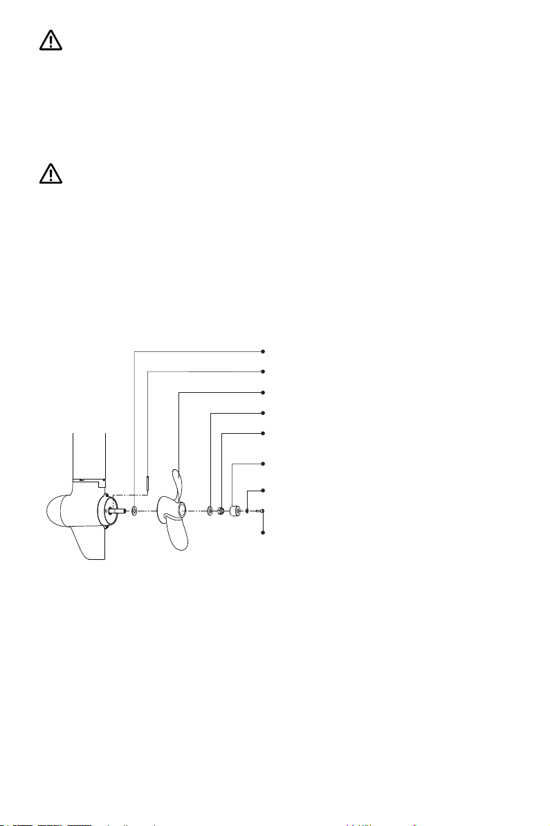
Bei der Verwendung von E-Serie-Batterien der Fa. ePropulsion ist ein einwand-
Schritt 2: Stift in das Loch des Schaftes schieben.
freier Betrieb gewährleistet, wenn die Batterie richtig angeschlossen ist. Bei der
Verwendung von E-Serie-Batterien anderer Hersteller muss der Benutzer vor der
Erstinbetriebnahme über die Evo Fernsteuerung bzw. Evo Pinne die Batteriekonguration manuell durchführen, um den Batteriestand genauer anzeigen zu lassen.
Für die Reihen- oder Parallelschaltung müssen baugleiche Batterien verwendet
werden. Das Modell, die Kapazität, das Baujahr und der Hersteller müssen identisch sein. Eine Nichtbeachtung führt zu Batterieschäden.
2.2 Einbau des Propellers
Beim Navy 3.0 Evo ist der Propeller bei der Lieferung ab Werk bereits eingebaut.
Nachfolgend wird beschrieben, wie Sie einen bereits eingebauten Propeller ersetzen
und einen neuen Propeller einbauen.
Schritt 1: Ø12-Unterlegscheibe montieren.
Schritt 3: Propeller einbauen.
Schritt 4: Ø12-Unterlegscheibe montieren.
Schritt 5: Mutter mit einem 19-mm-Steckschlüssel festziehen.
Schritt 6: Anode montieren.
Schritt 7: Ø6-Unterlegscheibe montieren.
Schritt 8: Mutter mit einem M6-Sechskantschlüssel festziehen.
Abb. 2-1
Für Navy 6.0 Evo Außenborder stehen zwei Propellertypen zur Verfügung. Benutzer
müssen vor der Inbetriebnahme den Propeller selbst einbauen. Je nach Voraussetzungen kann der Benutzer einen passenden Propeller auswählen. Für schwere Boote
mit einem großen Antrieb eignen sich Propeller mit kleinerer Steigung. Im Gegensatz
dazu eignen sich Propeller mit einer größeren Steigung für leichte und schnelle Boote.
Im Lieferumfang des Navy 6.0 Evo sind zwei Propeller mit jeweils einer kleineren Steigung und einer größeren Steigung enthalten. Der Propeller mit der kleineren Steigung
und größerem Durchmesser kann einen größeren Antrieb bei kleiner Geschwindigkeit
70
Page 73
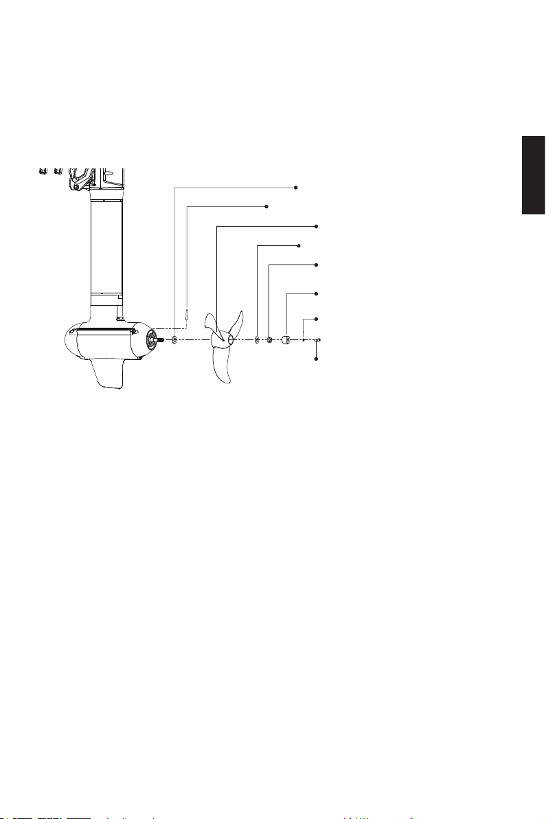
erzeugen. Dadurch erzielt der Motor bei einer niedrigen Geschwindigkeit höhere Betriebsleistung. Im Gegensatz dazu erzeugt ein Propeller mit einer größeren Steigung
angemessenen Antrieb, der für eine schnelle Fahrt des Bootes wichtig ist. Bei einer
Bootsgeschwindigkeit von mehr als 15 km/h ist der Propeller mit größerer Steigung
besser geeignet, denn er hat nur eine begrenzte Leistung bei niedriger Geschwindigkeit.
Schritt 1: Ø16-Unterlegscheibe montieren.
Schritt 2: Stift in das Loch des Schaftes schieben.
Schritt 3: Propeller einbauen.
Schritt 4: Ø12-Unterlegscheibe montieren.
Schritt 5: Mutter mit einem
19-mm-Steckschlüssel festziehen.
Schritt 6: Anode montieren.
Schritt 7: Ø6-Unterlegscheibe montieren.
Schritt 8: Mutter mit einem
M6-Sechskantschlüssel festziehen.
Abb. 2-2
Deutsch
71
Page 74
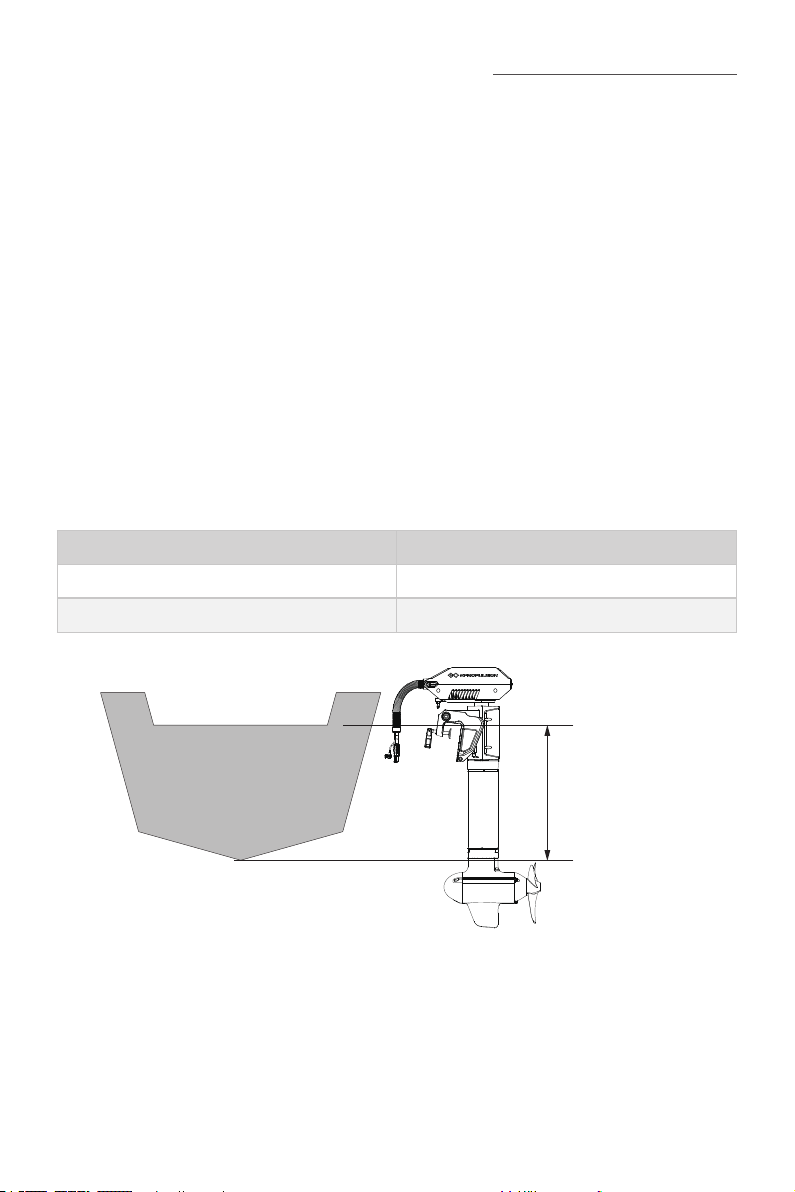
3 Einbau des Außenborders
Der Außenborder muss auf der Linie in der Mitte des Bootes eingebaut werden. Bei
Booten mit asymmetrischen Formen konsultieren Sie bitte Ihren Vertragshändler für
die beste Einbauposition. Je nach Höhe des Heckspiegels einen Außenborder mit der
passenden Schaftlänge auswählen. Die Oberkante des Propellers muss sich 100 bis
150 mm unter dem Wasserspiegel benden.
3.1 Einbauposition
Die Einbauhöhe des Außenborders hat einen großen Einuss auf die Fahrgeschwindigkeit. Bei einer zu hohen Einbauhöhe kann Kavitation entstehen, was zur Geschwindigkeitssenkung, Energieverschwendung und Propellerschäden führen kann. Bei einer
zu niedrigen Einbauhöhe können die Fahrgeschwindigkeit und die Betriebsleistung
des Motors durch Wasserwiderstand negativ beeinusst werden.
Die ideale Einbauhöhe hängt vom Boot ab. Um diese Höhe zu bestimmen, empfehlen
wir, bei unterschiedlichen Einbauhöhen Testfahrten durchzuführen.
Heckspiegelhöhe/Anwendungen Empfohlene Modelle
400 mm – 500 mm Navy 3.0 Evo-S / Navy 6.0 Evo-S
> 500 mm Navy 3.0 Evo-L / Navy 6.0 Evo-L
Abb. 3-1 Navy 6.0 Evo
72
Oberkante des
Heckspiegels
Heckspiegelhöhe
Unterkante Boot
Page 75
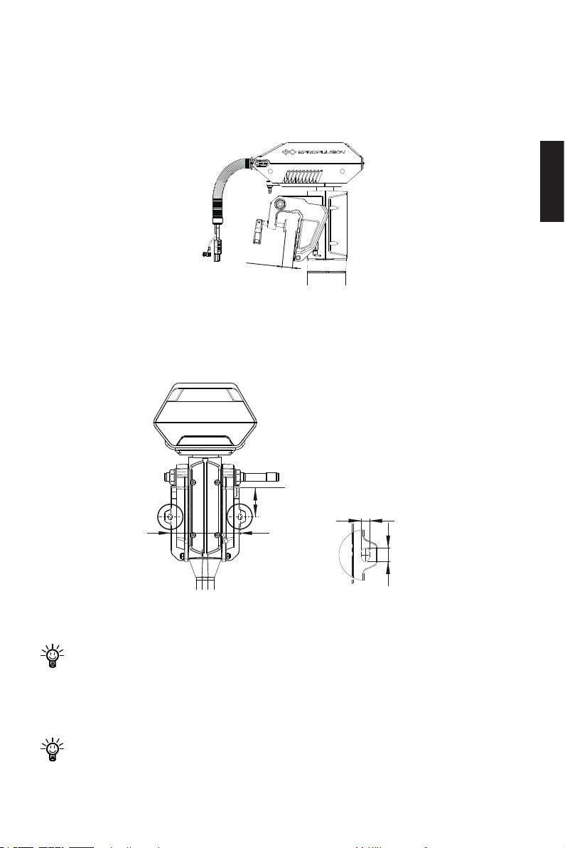
3.2 Einbau des Außenborders
Variante 1
Den Klemmhebel der Haltung im Uhrzeigersinn drehen, um den Außenborder auf dem
Spiegel zu befestigen.
30~70mm
Abb. 3-2
Variante 2
Den Außenborder mit zwei Schrauben im Rumpf einbauen. Abmessungen der Einbauöffnungen siehe Abbildung unten.
Deutsch
86mm
Oberkante des Heckspiegels
175mm
10mm
16mm
Abb. 3-3
Sicherstellen, dass die Halterung des Außenborders arretiert ist. Beim Lösen des
Klemmhebels kann der Außenborder ins Wasser fallen und dabei beschädigt
werden. Vor jedem Betrieb die Schrauben oder den Klemmhebel der Halterung
auf festen Sitz kontrollieren. Sie können sich durch Vibration lösen.
Es wird empfohlen, den Außenborder zusätzlich mit einem Seil oder einer Kette
zu sichern. Das Seil an einem festen Anschlagpunkt im Boot befestigen.
73
Page 76
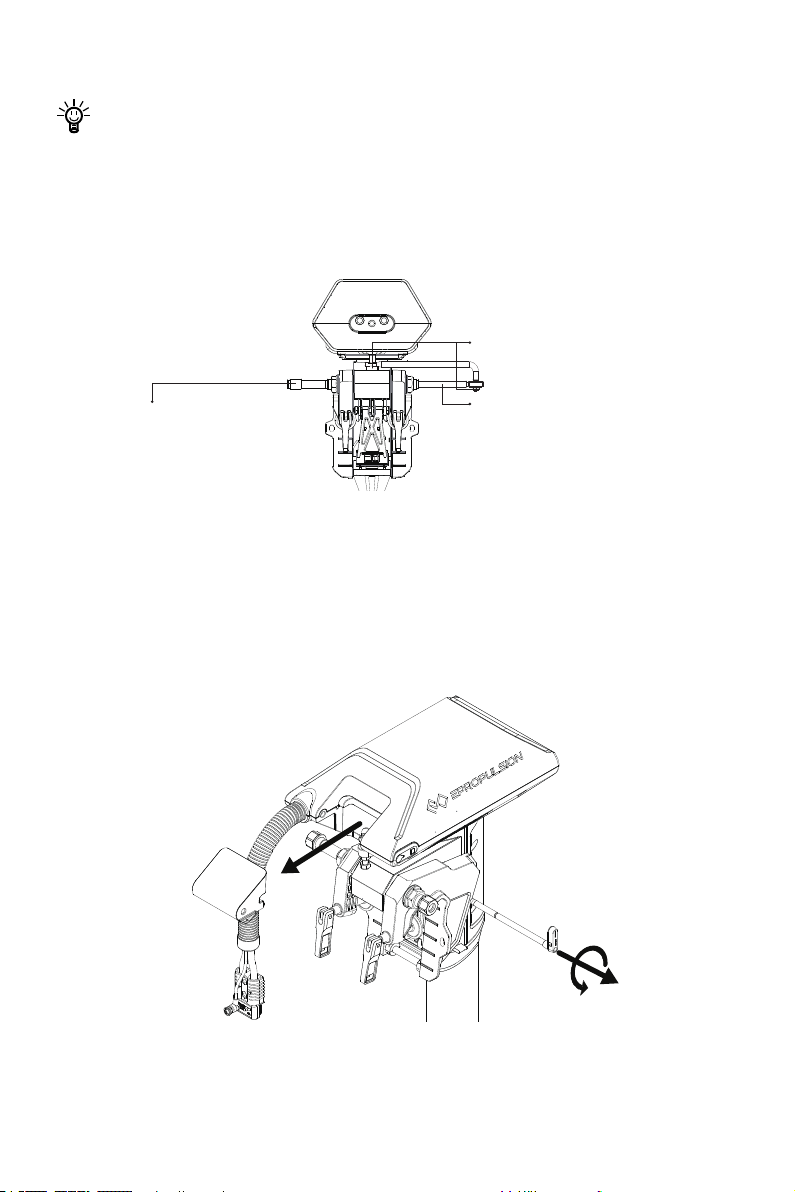
3.3 Einbau der Lenkung
Schritt 2: Winkelstange mit zwei
M8-Schrauben befestigen
Schritt 3: Die Lenkradachse
mit dem Gewinde auf der Winkelstange befestigen
Schritt 1: Die Lenkradachse in
die Winkelstange schieben
Bohrungen anhand der Schablone an den richtigen Stellen herstellen. Die Evo
Fernsteuerung vor der Inbetriebnahme durch die Bohrungen befestigen.
Bei Verwendung der Evo Fernsteuerung ein Lenkrad bereitstellen (nicht im Lieferumfang des Navy Evo Außenborders oder der Evo Fernsteuerung enthalten) und an dem
richtigen Einbauort für die Lenkung des Bootes befestigen.
Abb. 3-4
3.4 Einbau der Evo Pinne
1. Die Pinnenachse gegen den Uhrzeigersinn drehen. Zusammen mit dem Deckel herausziehen
Abb. 3-5
74
Page 77
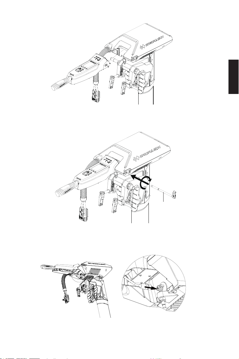
2. Die Evo Pinne in die vorgegebene Position des Motors einbauen.
Abb. 3-6
3. Die Pinnenachse bis zum Anschlag in die Öffnung schieben und im Uhrzeigersinn
festschrauben.
Deutsch
Pinnenachse
Abb. 3-7
4. Das Verbindungskabel der Evo Pinne in die vorgesehene Buchse stecken.
Abb. 3-8
75
Page 78
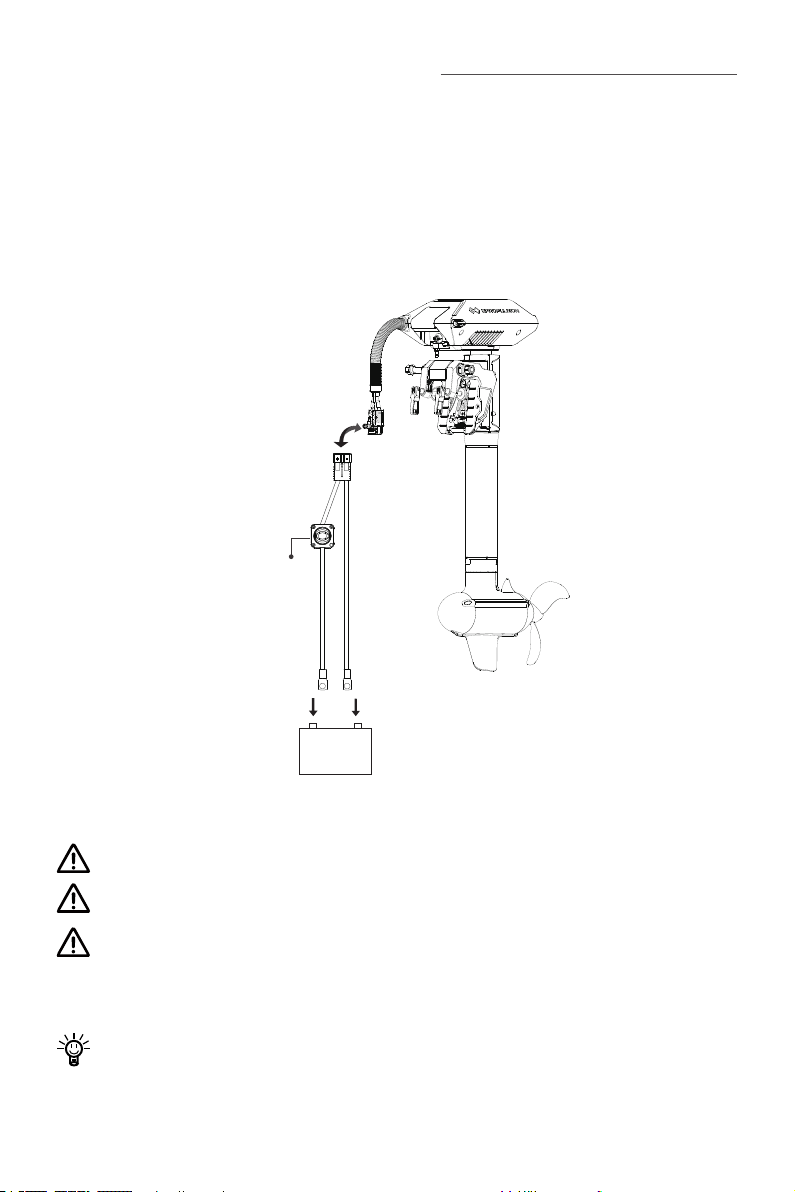
4 Anschluss der Batterie
Hauptschalter
①
②
+ -
48V
+ -
4.1 Anschluss einer 48-V-Batterie
Vor dem Anschluss der Batterie muss sichergestellt werden, dass der Hauptschalter
ausgeschaltet ist.
1. Den Hauptschalter mit der Batterie verbinden.
2. Das Netzkabel des Hauptschalters mit dem Netzkabel des Außenborders
verbinden.
Kurzschluss der Batterie vermeiden.
Unterbricht die Stromversorgung, wird der Außenborder gestoppt.
Kurzschluss zwischen dem Hauptschalter und anderen Stromquellen vermeiden. Der Hauptschalter muss im Boot fest eingebaut werden. Die Rückwand des
Hauptschalters darf niemals entfernt werden.
Vor dem Betrieb den Hauptschalter im Uhrzeigesinn drehen, um die Spannungsversorgung der Batterie einzuschalten.
Abb. 4-1
76
Page 79
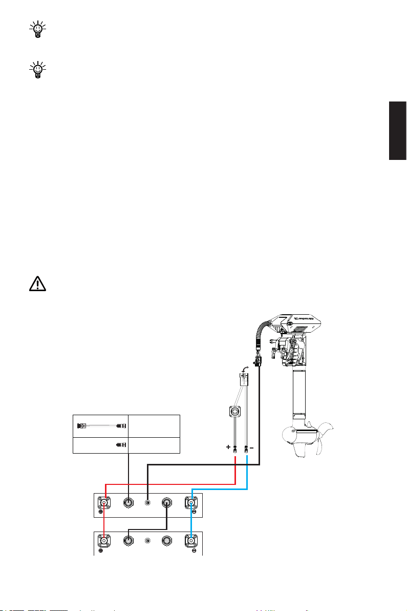
Die Kapazität kann auch durch mehrere parallel geschalteten Batterien vergrö-
CAN-IN CAN-OUTMOTOR
CAN-IN CAN-OUTMOTOR
BUS Fernschalter
inkl. Terminator
BUS Terminator
Batterie der E-Serie
Batterie der E-Serie
Verbindungskabel
Batterie E-Serie
ßert werden.
Nach einem langen Einsatz können sich die Verbindungsschrauben des Hauptschalters und Netzkabels lösen. Lockere Verbindungsschrauben verursachen
Wackelkontakte. Zur Fehlerbehebung öffnen Sie die Rückwand des Schalters
und ziehen Sie die Schrauben wieder fest.
4.2 Anschluss der E-Serie-Batterien
Vor dem Anschluss der Batterie muss sichergestellt werden, dass der Hauptschalter
ausgeschaltet ist.
1. Batterien mit Verbindungs- und Überbrückungskabeln parallel schalten.
2. Den Hauptschalter mit der E-Serie-Batterie verbinden.
3. Den Steckverbinder des Hauptschalter-Netzkabels mit dem Steckverbinder des
Außenborder-Netzkabels verbinden.
4. Die E-Serie-Batterie mit dem Verbindungskabel an den Navy Evo Außenborder
anschließen.
Für genauere Batterie-Daten werden Verbindungskabel für Kommunikationszwecke empfohlen.
Deutsch
Abb. 4-2
77
Page 80
Kurzschluss der Batterie vermeiden.
Wird das Verbindungs- oder das Netzkabel unterbrochen, wird der Außenborder
sofort gestoppt.
Kurzschluss zwischen dem Hauptschalter und anderen Stromquellen vermeiden. Der Hauptschalter muss im Boot fest eingebaut werden. Die Rückwand des
Hauptschalters darf niemals entfernt werden.
Um zwei oder mehrere E-Serie-Batterien parallel zu schalten, werden spezielle
Verbindungskabel für die E-Serie benötigt.
Vor dem Betrieb den Hauptschalter im Uhrzeigersinn drehen, um die Spannungsversorgung der Batterie einzuschalten.
Die Kapazität kann auch durch mehrere parallel geschaltete Batterien vergrößert
werden.
Nach einem langen Einsatz können sich die Verbindungsschrauben des
Hauptschalters und Netzkabels lösen. Lockere Verbindungsschrauben verursachen Wackelkontakte. Zur Fehlerbehebung öffnen Sie die Rückwand des Schalters und ziehen Sie die Schrauben wieder fest.
4.3 Reihen-/Parallelschaltung der Batterien
Wie in Abbildung 4-3 dargestellt, vier 12-V-Batterien mit Verbindungskabeln in Reihe
schalten. Dadurch einen 48-V-Batteriesatz für die Spannungsversorgung des Navy
Evo Außenborders herstellen. Das mit + bezeichnete Verbindungskabel des Hauptschalters muss an den Pluspol der Batterie angeschlossen werden. Das zweite Kabel
mit dem Minuspol der Batterie verbinden.
78
Page 81
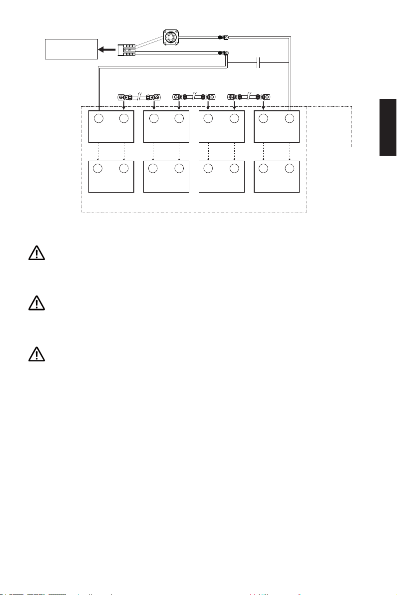
Außenborder
48V
Verbindungskabel
-
+
12V
- +
12V
Paral-
lelschaltung
Batterie
Verbindungskabel
-
12V
- +
12V
Batterie
+
Verbindungskabel
- +
12V
- +
12V
Batterie
- +
12V
- +
12V
Reihen-
schaltung
Abb. 4-3
Kurzschluss zwischen dem Hauptschalter und anderen Stromquellen vermeiden. Der Hauptschalter muss im Boot fest eingebaut werden. Die Rückwand des
Hauptschalters darf niemals entfernt werden.
Für die Reihen- oder Parallelschaltung müssen baugleiche Batterien verwendet
werden. Das Modell, die Kapazität, das Baujahr und der Hersteller müssen identisch sein. Eine Nichtbeachtung führt zu Batterieschäden.
Die Polarität darf niemals vertauscht werden. Bei der Reihen- oder Parallelschaltung der Batterien besondere Vorsicht wahren. Nach der Arbeit die Schaltung
noch einmal gemäß Abbildung 4-3 kontrollieren.
Deutsch
79
Page 82
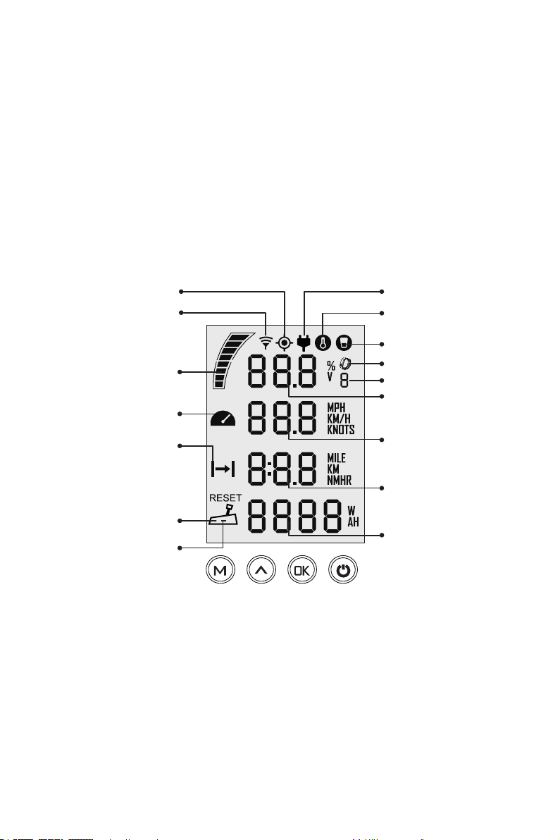
5 Evo Fernsteuerung / Evo Pinne
Die Evo Fernsteuerung / Evo Pinne dient zum Start/Stop des Außenborders, zur Einstellung der Fahrgeschwindigkeit und der Batterieparameter und zum Anzeigen der
Systemmeldungen. Die Stromversorgung der Evo Fernsteuerung kann über eine Solaranlage oder integrierte Lithium-Ionen-Batterien erfolgen. Die Evo Pinne wird über
Verbindungskabel vom Motor mit Strom versorgt. Die Evo Fernsteuerung kann über
ein Kabel oder kabellos mit dem Außenborder kommunizieren. Die Evo Pinne kann
nur über Kabel mit dem Außenborder verbunden werden. Bei der Evo Fernsteuerung
wird auch ein Lenkrad benötigt. Die Evo Pinne besitzt bereits die Lenkfunktion.
5.1 LCD-Display
GPS-Status
Anzeige kabellose Verbindung
Anzeige Batteriestand
Störung Ventilator
Anzeige zurückgelegter
Strecke oder Zeit
/verbleibender Strecke oder
Zeit
Gashebel in die NULL-Posi-
tion (RESET)
Schwachstromanzeige der
Fernbedienung
Abb. 5-1
Rekuperationsanzeige
Warnung Übertemperatur
Hinweis Reißleinenschalter
Hinweis Sicherheitsarmband
Anzahl angemeldeter
Sicherheitsarmbänder
Batteriestand/Spannung
Ist-Geschwindigkeit
Strecke/Zeit
Leistung
80
Page 83
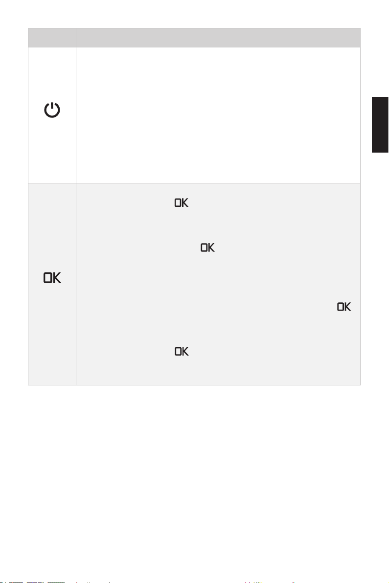
Tasten Funktionen
1. Im ausgeschalteten Zustand wird die Evo Fernsteuerung / Evo Pinne eingeschaltet, wenn die EIN/AUS-Taste gedrückt und kurz gehalten
wird.
2. Im eingeschalteten Zustand wird die Evo Fernsteuerung / Evo Pinne
„EIN/AUS“
„OK“
ausgeschaltet, wenn die EIN/AUS-Taste gedrückt und kurz gehalten
wird.
3. Im eingeschaltetem Zustand kann die Hintergrundbeleuchtung des
Displays durch kurzes Drücken der EIN/AUS-Taste ein- bzw. ausgeschaltet werden.
1. Durch Drücken der „ “ Taste im Setup-Menü kann die aktuelle
Einstellung gespeichert werden. Die nächste Option wird dann angewählt.
2. Durch langes Drücken der „ “ Taste im Setup-Menü wird die aktuelle Einstellung gespeichert und anschließend zum Hauptmenü gewechselt.
3. Wenn das Hauptmenü erscheint oder auf dem Display alle Zeichen
zu sehen sind, kann durch langes Drücken (5 Sekunden) der „ “
Taste zum Menü für die Kopplung der Evo Fernsteuerung / Evo Pinne
gewechselt werden.
4. Durch Drücken der „ “ Taste im Hauptmenü kann die Anzeige
zwischen „Spannung V“ und „Batteriestand %“ gewechselt werden.
Deutsch
81
Page 84
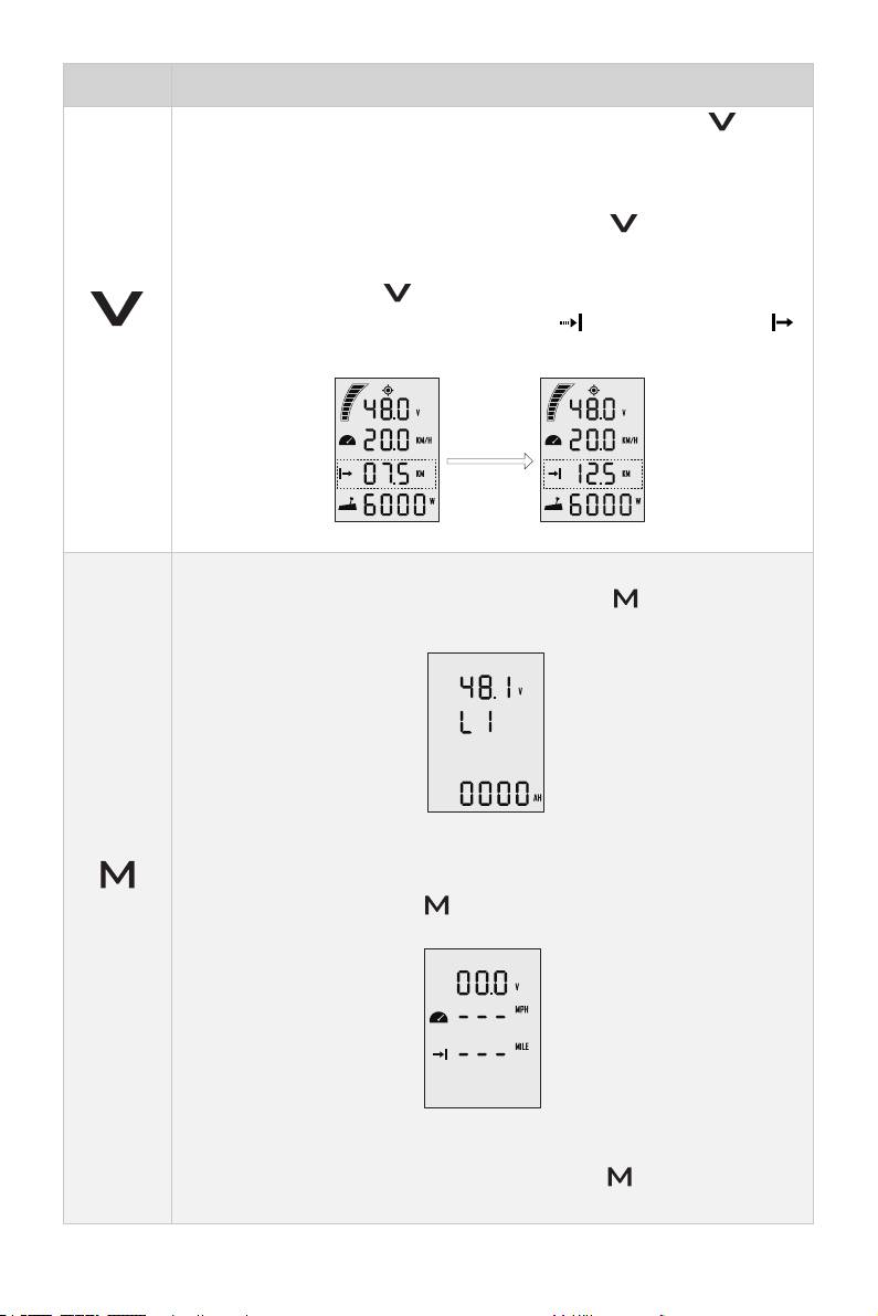
Tasten Funktionen
^
1. Im beliebigen Setup-Menü können durch Drücken der „^“ Taste
die Optionen für das Setup angezeigt werden.
2. Im eingeschalteten Zustand und beim Erscheinen des Hauptmenüs
kann durch langes Drücken (10 Sekunden) der „^“ Taste zum Menü
für die Kalibrierung des Gashebels gewechselt werden.
3. Durch Drücken der „^“ Taste im Hauptmenü können die Anzeigen
der Strecke oder Zeit zwischen Symbol „ “ (verbleibend) und „ “
„Auswahl“
(zurückgelegt) gewechselt werden.
Drücken der
„Auswahl“
Taste
Hauptmenü 1 Hauptmenü 2
1. Im eingeschalteten Zustand und beim Erscheinen des Hauptmenüs
kann durch Drücken (kurz gedrückt halten) der „ “ Taste zum Menü
der benutzerdenierten Einstellungen gewechselt werden.
„Menü“
Menü der benutzerdenierten Einstellungen
2. Im Menü der benutzerdenierten Einstellungen kann durch Drücken
(kurz gedrückt halten) der „ “ Taste in das Setup-Menü für die Batterie gewechselt werden.
Setup-Menü für die Batterie
3. Im beliebigen Menü kann durch Drücken der „ “ Taste zum Hauptmenü gewechselt werden.
82
Page 85
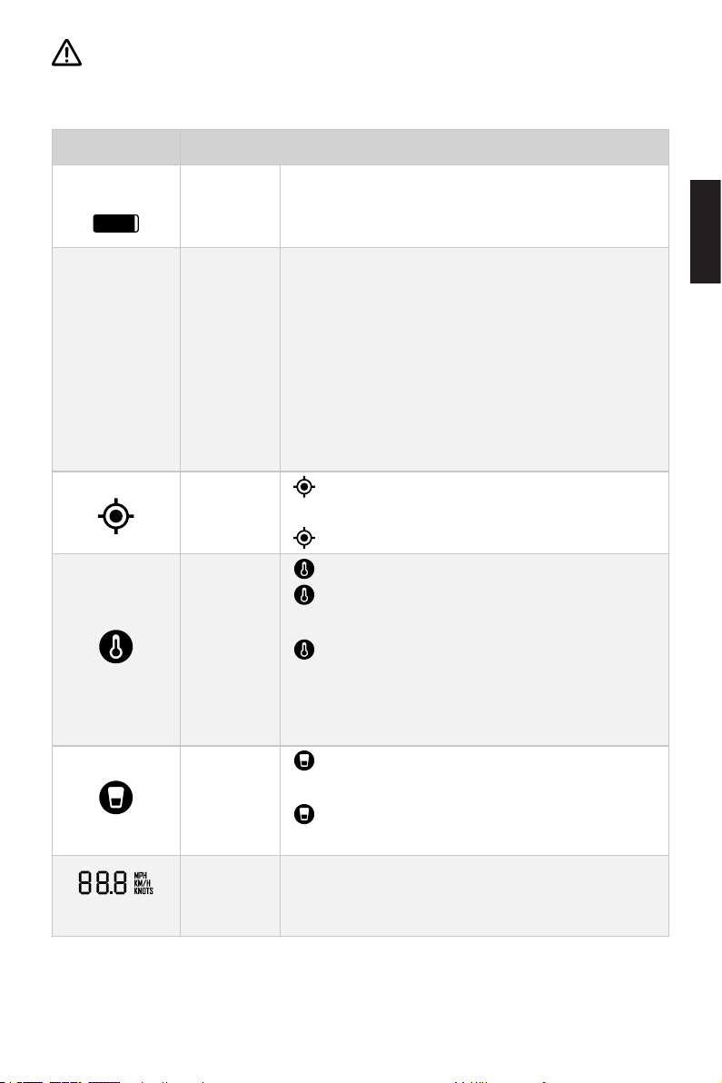
Werden keine Änderungen zu den Parametern in diesem Menü vorgenommen,
48.0V
48.0V
so werden die angezeigten Werte als Voreinstellungen für den Benutzer gespeichert.
Beschreibung Funktionen
Batteriestand
Anzeige
Batteriestand /
Spannung
GPS-Status
Anzeige
Warnung
Übertemperatur
Reißleinenschalter
Status
Ist-Geschwindigkeit
Batteriestandsanzeige (ungefähr).
Schwarze Felder zeigen verbleibende Batterieladung.
Genaue Anzeige des aktuellen Batteriestands (%) /
Batteriespannung.
Kongurationen können im Menü der benutzerdenierten Einstellungen vorgenommen werden.
Beispiel:
100%
: digitale Darstellung des aktuellen Batte-
riestands.
: Anzeige der aktuellen Batteriespannung.
Leuchtet nicht: kein Empfang oder GPS funktio-
niert nicht.
Leuchtet dauerhaft: GPS-Empfang vorhanden.
Leuchtet nicht: Temperatur im Normalbereich.
Blinkend: Temperatur leicht erhöht, maximale
Leistungsaufnahme des Motors wird gesenkt.
Leuchtet dauerhaft: Temperatur zu hoch. Aussenborder schaltet sich aus. Erst nach Erreichen
einer niedrigeren Temperatur kann der Außenborder wieder eingeschaltet werden.
Leuchtet nicht: Reißleinenschalter eingebaut
und System im Betrieb.
Leuchtet dauerhaft: Reißleinenschalter nicht
angeschlossen.
Zeigt die Echtzeit-Fahrgeschwindigkeit des Bootes
an. Im „Unit Setting“ Menü kann die gewünschte Einheit (KM/H, MPH oder KNOTS) eingestellt werden.
Deutsch
83
Page 86
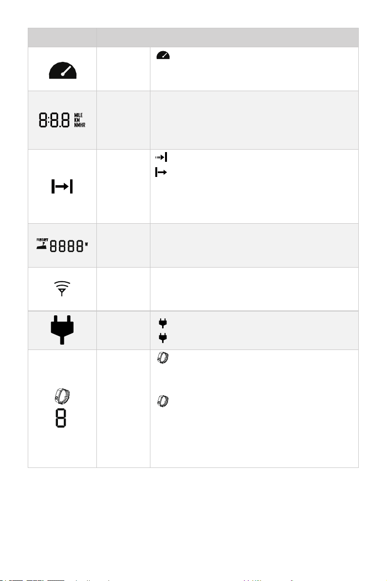
Beschreibung Funktionen
Störung
Ventilator
Anzeige
Strecke /
Zeit
Zurückgelegte Strecke / verbleibende
Strecke
Leistung
Gashebel
Anzeige
kabellose
Verbindung
Rekuperationsanzeige
Blinkt: Ventilator hat Störung. Die Verdrahtung
des Ventilators durch Ihren Vertragshändler
überprüfen lassen.
Anzeige der Echtzeit-Strecke / Zeit.
Im Menü „Unit Setting“ kann die gewünschte Einheit,
MILE, KM (Kilometer) oder NM (Seemeile), eingestellt werden. Die Zeit wird in Stunden angezeigt.
: verbleibende Strecke oder Zeit.
: zurückgelegte Strecke oder abgelaufene Zeit.
Im Menü „Unit Setting“ kann die gewünschte Einheit,
MILE, KM (Kilometer) oder NM (Seemeile), eingestellt werden. Die Zeit wird in Stunden angezeigt.
Zeigt die Echtzeit-Leistung des Geräts an.
Blinkendes Symbol bedeutet, dass der Gashebel in
die NULL-Position geschaltet werden soll.
Zeigt an, dass zwischen der Evo Fernsteuerung
und des Außenborders eine kabellose Verbindung
besteht.
Leuchtet dauerhaft: Rekuperation ist aktiviert.
Blinkt: Die Batterie wird vom Motor geladen.
Verbindungsanzeige
Sicherheitsarmband
Leuchtet dauerhaft: Das Sicherheitsarmband
wurde erfolgreich mit der Evo Fernsteuerung /
Evo Pinne verbunden.
Blinkt: Mindestens ein Sicherheitsarmband
nicht verbunden.
Die Zahl steht für die Anzahl der mit der Evo
Fernsteuerung / Evo Pinne verbundenen Sicher-
heitsarmbänder.
84
Page 87
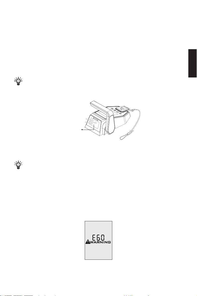
5.2 Laden
Die Evo Fernsteuerung besitzt eine integrierte Batterie als Stromversorgung. Beim
normalen Betrieb wird die Batterie automatisch geladen, entweder über Solarenergie
oder das Ladekabel.
5.2.1 Laden über Solarenergie (empfohlen)
Beim Empfang ausreichender Sonnenstrahlung auf dem Solarpanel wird die integrierte Lithium-Batterie automatisch geladen.
Um eine schnellere Ladung zu gewährleisten, sollte das Solarpanel ins Sonnenlicht gestellt werden.
Solarmodul
(zur Sonne hin
ausgerichtet)
Abb. 5-2
Deutsch
Es wird empfohlen, über das Solarpanel zu laden.
5.2.2 Laden über Ladekabel
Wenn die Evo Fernsteuerung über längere Zeit nicht genug Sonnenstrahlung bekommt, wird die Batterie weiter entladen. In diesem Fall erscheint auf dem Display der Evo
Fernsteuerung der Fehlercode E60 (Abb. 5-3). Diese Warnmeldung weist darauf hin,
dass die Evo Fernsteuerung geladen werden soll.
Abb. 5-3
85
Page 88
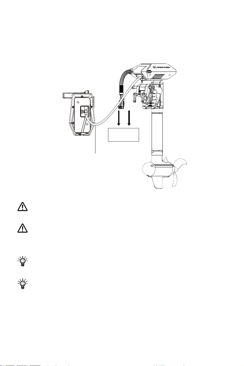
In diesem Fall kann das Laden durch ein Ladekabel beschleunigt werden.
Die Evo Fernsteuerung mit einem Verbindungskabel an das Kommunikationsmodul
/ den Antrieb des Außenborders anschließen. Die Verbindung zwischen der Batterie
und dem Außenborder aufrechterhalten und die Stromversorgung einschalten.
Batterie
Verbindungskabel
Abb. 5-4
Bei einer Langzeitlagerung sollte die Evo Fernsteuerung einmal alle sechs Monate vollständig aufgeladen werden, um eine Tiefentladung zu vermeiden.
Kurzschluss zwischen dem Hauptschalter und anderen Stromquellen vermeiden. Der Hauptschalter muss im Boot fest eingebaut werden. Die Rückwand des
Hauptschalters darf niemals entfernt werden.
Vor der Inbetriebnahme nach einer Langzeitlagerung laden Sie die Evo Fernsteuerung zuerst vollständig auf.
Wenn Sie die Evo Fernsteuerung während des Ladens einschalten und damit
den Außenborder ansteuern, wird der Außenborder sofort gestoppt, wenn die
Kabelverbindung zwischen dem Motor und der Evo Fernsteuerung unterbricht. In
diesem Fall muss der Außenborder neu eingeschaltet werden.
86
Page 89
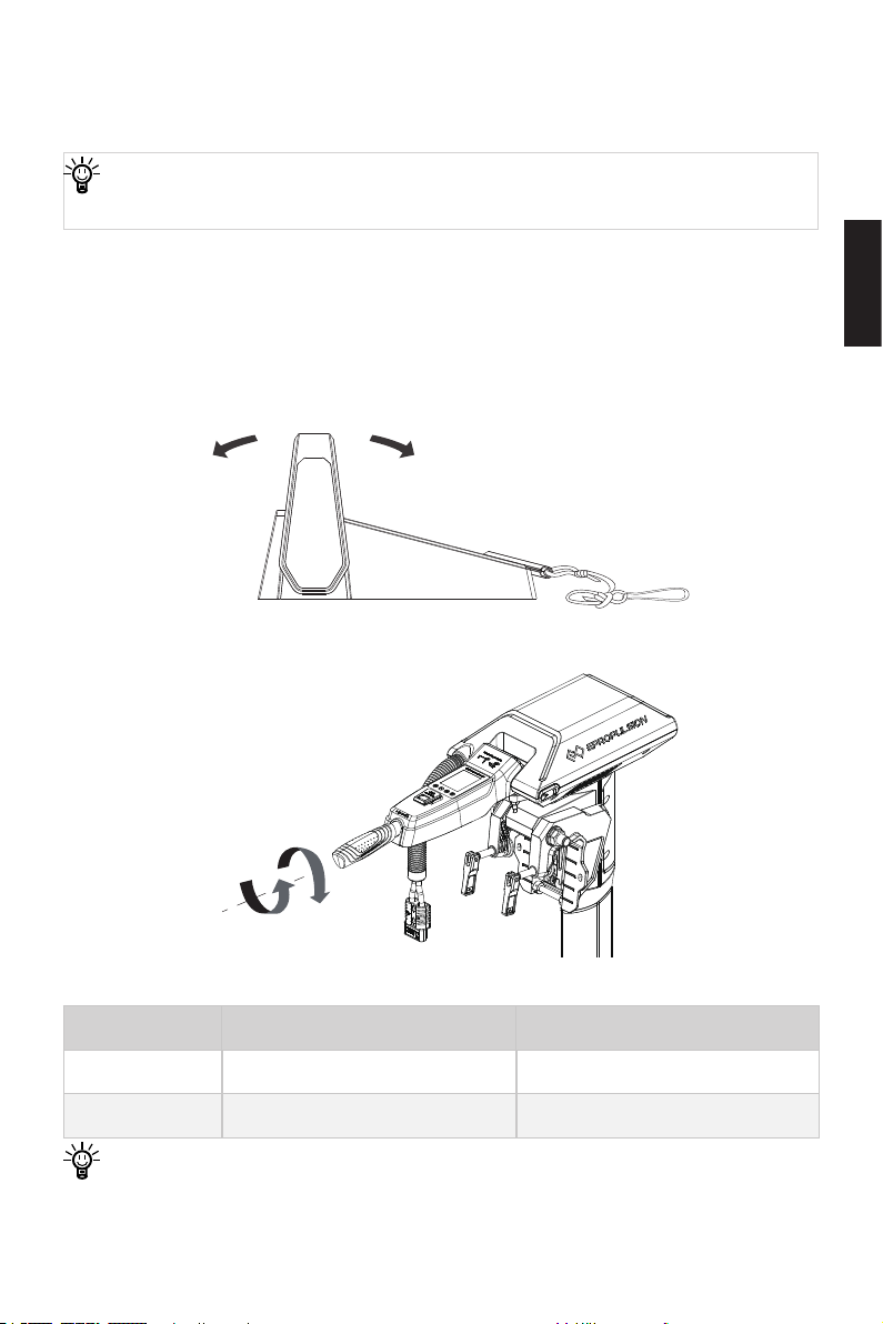
5.3 Leistungseinstellung
NULL
5.3.1 Leistung einstellen
Vor der Inbetriebnahme muss der Reißleinenschalter auf die Evo Fernsteuerung
aufgelegt werden.
Die Evo Fernsteuerung dient zum Einstellen der Leistungsaufnahme des Außenborders. Nach dem ordnungsgemäßen Anschluss der Batterie die Evo Fernsteuerung
einschalten und den Außenborder starten. Den Gashebel anschließend langsam in
die Position „Vorwärts“ bewegen, um die Leistung dadurch zu erhöhen. Maximale
Vorwärts- und Rückwärtsleistung siehe Tabelle unten.
Deutsch
Vorwärts
Rückwärts
Evo Remote Control
Abb. 5-5
Rückwärts
Vorwärts
NULL
Abb. 5-6
Modell Maximale Vorwärtsleistung Maximale Rückwärtsleistung
Navy 3.0 Evo 3 kW 3 kW
Navy 6.0 Evo 6 kW 6 kW
Vor dem Einschalten der Evo Fernsteuerung / Evo Pinne muss der Gashebel in
die NULL-Position gebracht werden.
87
Page 90
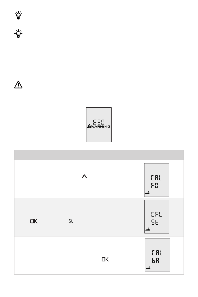
Falls „RESET“ auf dem LCD-Display erscheint, muss der Gashebel in die
NULL-Position gebracht werden.
Wenn der Gashebel direkt von einer Vorwärts-Position in die Rückwärts-Position
bewegt wird, wird der Außenborder zuerst für eine kürzere Zeit gestoppt, bevor
er in die entgegengesetzte Richtung dreht.
5.3.2 Kalibrieren
Wenn der Fehlercode wie in der Abb. 5-7 auf dem Display erscheint, muss der Gashebel genau nach den unten beschriebenen Schritten kalibriert werden.
Vor der Kalibrierung den zugehörigen Reißleinenschalter auf die vorgesehene
Position legen. Andere magnetische Gegenstände dürfen nicht als Ersatz für den
Reißleinenschalter verwendet werden.
Abb 5-7
Neukalibrierungsprozess LCD-Display-Anzeigen
Schritt 1: Drücken Sie die Taste „
bis „CAL FO“ angezeigt wird.
Schritt 2: Bringen Sie den Geschwindigkeitsregler in die
maximale Vorwärts-Stellung und drücken Sie dann die
Taste „ “. Es wird „CAL “ angezeigt, wobei „CAL“
blinkt.
Schritt 3: Ziehen Sie den Geschwindigkeitsregler in die
mittlere (Leerlauf-)Position, wo Sie ein Klickgeräusch
hören werden, drücken Sie dann die Taste „ “, „CAL
bA“ wird angezeigt und „CAL“ blinkt.
“ 10 Sekunden lang,
88
Page 91
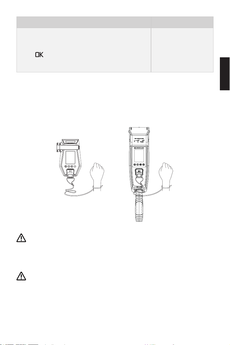
Neukalibrierungsprozess LCD-Display-Anzeigen
Schritt 4: Bringen Sie den Geschwindigkeitsregler in die
maximale Rückwärts-Stellung und drücken Sie dann die
Taste „ “. Es wird automatisch zur Hauptseite zurückkehren.
5.4 Reißleinenschalter einsetzen
Die Reißleine um Ihr Handgelenk legen oder an Ihrer Schwimmweste befestigen.
Im Notfall kann der Motor durch Entfernen des Reißleinenschalters gestoppt werden.
Vor dem erneuten Start des Motors muss der Reißleinenschalter wieder auf die
vorgesehene Position angebracht werden.
Abb. 5-8
Der Reißleinenschalter erzeugt ein Magnetfeld. Zwischen Personen mit
Herzschrittmachern oder implantierten Defibrillatoren, magnetischen Karten
bzw. anderen magnetischen Gegenständen und dem Schalter muss ein Sicher-
heitsabstand von mindestens 50 cm eingehalten werden.
Deutsch
Das Magnetfeld des Reißleinenschalters beeinusst elektrische Messgeräte und
muss daher von ihnen ferngehalten werden.
89
Page 92
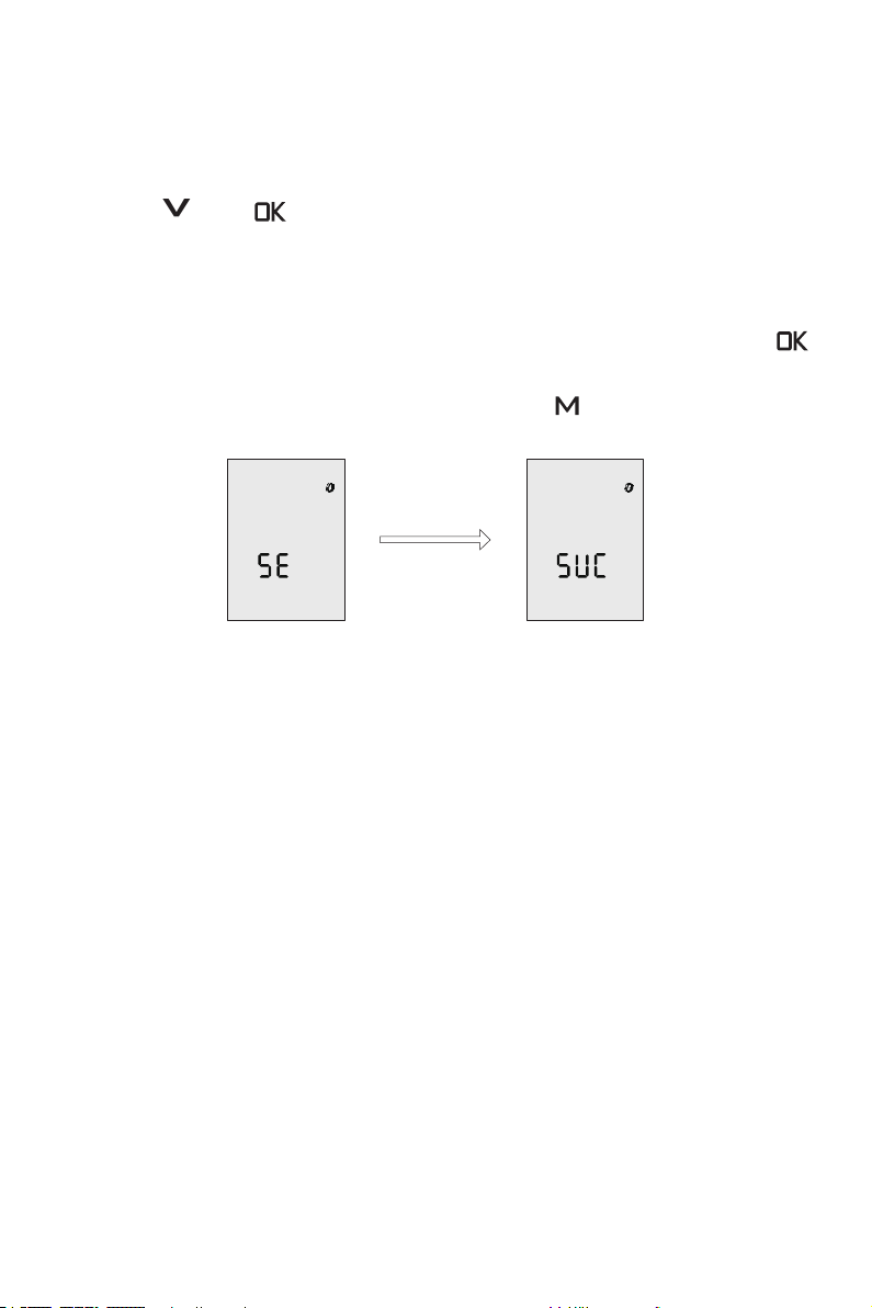
5.5 Sicherheitsarmband einsetzen
5.5.1 Registrierung des Sicherheitsarmbands mit der Evo Fernsteuerung / Evo Pinne (Kopplung)
Die Taste „^“ und „ “ drücken und kurz gedrückt halten. Auf dem Display erscheinen das Symbol für das Sicherheitsarmband und die Buchstaben SE. Das zu
registrierende Sicherheitsarmband in die Nähe bringen und einschalten. Wenn die
Buchstaben „SUC“ auf dem Display von der Evo Fernsteuerung / Evo Pinne erscheinen, dann ist die Kopplung erfolgreich abgeschlossen. Durch kurzes Drücken der „
“ Taste in diesem Menü können weitere Sicherheitsarmbänder (max. 8) registriert
werden. Nach dem Abschluss kann durch Drücken der „ “ Taste in das Hauptmenü
gewechselt werden.
Abb. 5-9
5.5.2 Mann-über-Bord-Schutz
Nach der erfolgreichen Registrierung der Sicherheitsarmbänder in der Evo Steuerung
wird der Außenborder sofort gestoppt, wenn ein Sicherheitsarmband ins Wasser
fällt und die Kommunikation mit der Evo Fernsteuerung dadurch unterbricht. Hierzu
muss die Evo Fernsteuerung im Betrieb sein. Das Display der Evo Steuerung fängt an
zu blinken und gibt einen warnenden Ton aus. Gleichzeitig blinkt das Symbol für das
Armband und die darunter stehende Zahl (Anzahl der gemeldeten Armbänder) wird
reduziert. Nachdem der Gashebel in die NULL-Position gebracht wird, kann der Motor
wieder betrieben werden. Das Warnsignal aus der Evo Steuerung hört auf zu blinken,
aber das Display blinkt weiter. Falls Sie sicher sind, dass die Warnung zurückgesetzt
werden soll, dann müssen Sie die Evo Steuerung oder das Sicherheitsarmband, das
die Verbindung mit der Steuerung verloren hat, neu starten.
5.5.3 Not-Aus
Nach der erfolgreichen Registrierung der Sicherheitsarmbänder in der Evo Steuerung
wird der Außenborder sofort gestoppt, wenn die Bedientaste des Sicherheitsarm-
90
Page 93
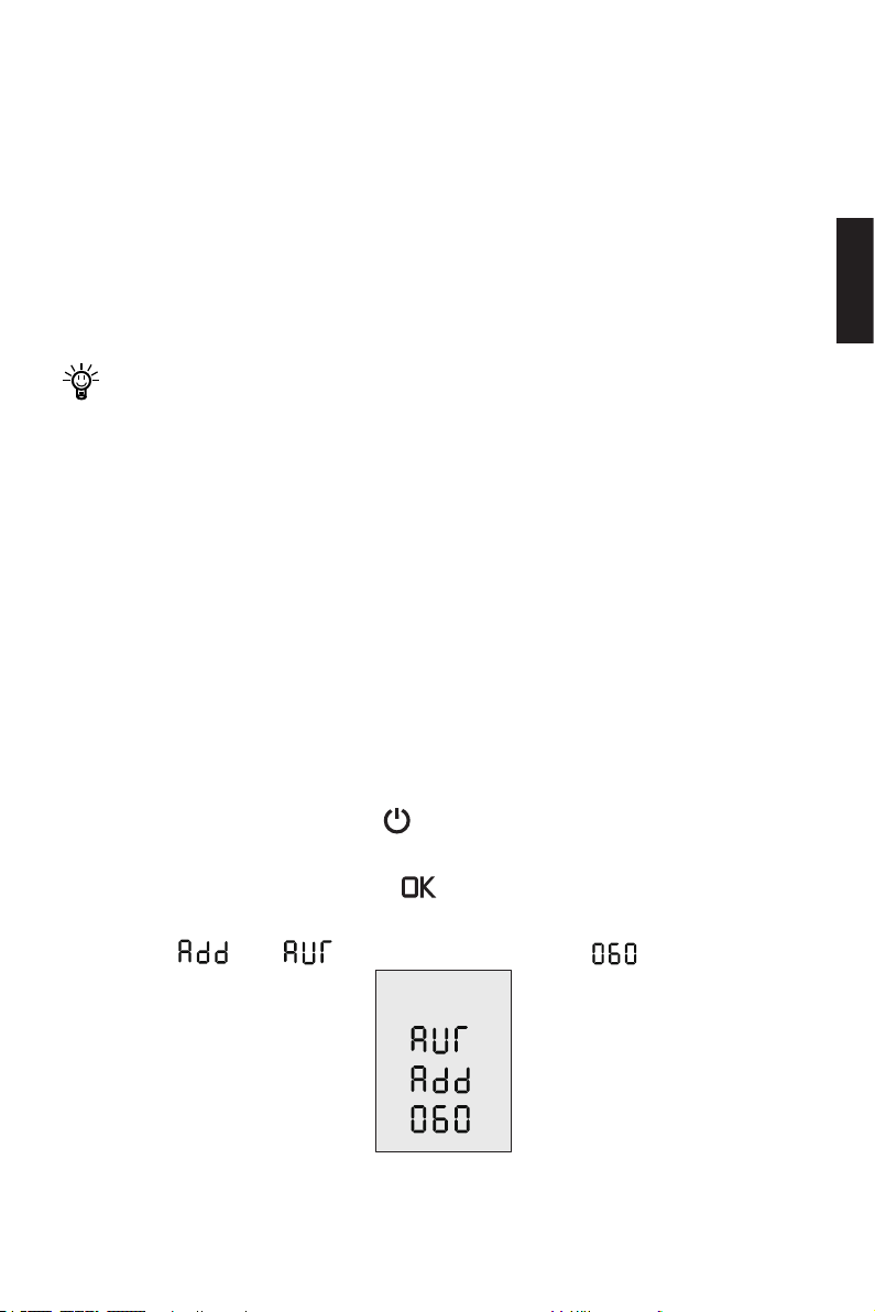
bands kurz betätigt wird. Dabei muss die Evo Fernsteuerung im Betrieb sein. Das
Display der Evo Steuerung fängt an zu blinken und gibt einen warnenden Ton aus.
Gleichzeitig blinkt das Symbol für das Armband und die darunter stehende Zahl
(Anzahl der gemeldeten Armbänder) wird reduziert. Nachdem der Gashebel in die
NULL-Position gebracht wird, kann der Motor wieder betrieben werden. Das Warnsignal aus der Evo Steuerung hört auf zu blinken, aber das Display blinkt weiter. Falls
Sie sicher sind, dass die Warnung zurückgesetzt werden soll, dann müssen Sie die
Evo Steuerung neu starten oder nach 5 Sekunden das Sicherheitsarmband betätigen,
damit es wieder in das Betriebsmodus wechselt.
Wenn ein Sicherheitsarmband die Verbindung verliert, oder nach einem Not-Aus,
wird die Stopp-Funktion der restlichen Armbänder vorerst deaktiviert, bis der
Normalzustand wiederhergestellt ist.
5.6 Registrierung der Evo Fernsteuerung im Außenborder (Kopplung)
Vor der Inbetriebnahme muss die Evo Fernsteuerung im Außenborder registriert
werden. Für die Registrierung gibt es zwei Möglichkeiten. Bitte eine der folgenden
Methode für die Registrierung auswählen und damit die Registrierung durchführen.
Methode 1: kabellos
Schritt 1: Den Außenborder und die Evo Fernsteuerung ausschalten. Die Evo Fernsteuerung in die Nähe (näher als 0,5 Meter) des Kommunikationsmoduls / Antriebs
des Außenborders bringen.
Deutsch
Schritt 2: Durch langes Drücken der „ “ Taste an der Evo Fernsteuerung einschalten.
Schritt 3: Sicherstellen, dass das Symbol für kabellose Verbindung dauerhaft leuchtet.
Schritt 4: Durch langes Drücken der „ “ Taste auf der Evo Fernsteuerung in das
Kopplungsmenü wechseln (Abb. 5-10). Im Kopplungsmenü nden Sie die blinkenden
Buchstaben „ “ und „ “ und einen Rückwärtszähler „ “.
Abb. 5-10
91
Page 94
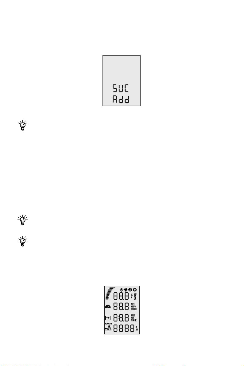
Schritt 5: Netzschalter einschalten und abwarten, bis die Kopplung des Außenborders
mit der Evo Fernsteuerung automatisch abgeschlossen ist.
Schritt 6: Nach dem Vorgang erscheint folgendes auf dem Display. (siehe Abbildung
unten)
Abb. 5-11
Falls die Kopplung nicht innerhalb von 60 Sekunden abgeschlossen wird, wieder-
holen Sie die Schritte ab 3.
Methode 2: Über Verbindungskabel
Schritt 1: Den Außenborder und die Evo Fernsteuerung ausschalten.
Schritt 2: Mit einem Verbindungskabel den Außenborder und die Evo Fernsteuerung
verbinden.
Schritt 3: Den Außenborder und die Evo Fernsteuerung einschalten. Die Kopplung ndet automatisch statt. Wenn das Hauptmenü erscheint, ist die Kopplung erfolgreich
abgeschlossen.
Auch wenn eine kabellose Verbindung bereits besteht, wechselt das Gerät in den
Kabelmodus, wenn ein Verbindungskabel angeschlossen wird.
Beim Wechsel auf eine neue Steuerung oder einen neuen Außenborder bleibt die
ursprüngliche Kommunikation nicht bestehen. Eine Störung der Verbindung wird
angezeigt. Auf dem Display der Evo Fernsteuerung wird das Hauptmenü wie
unten im Bild dargestellt. In diesem Fall muss die Kopplung erneut durchgeführt
werden.
Abb. 5-12
92
Page 95

Falls die Evo Fernsteuerung oder der Außenborder nicht ausgetauscht wurden
und das Hauptmenü trotzdem wie oben dargestellt wird, dann überprüfen Sie:
1) ob die Evo Fernsteuerung nah genug am Außenborder ist.
2) ob alle Geräte richtig eingeschaltet sind.
Falls das Display der Evo Fernsteuerung nach den Prüfungen das Hauptmenü
immer noch wie oben (Abb. 5-12) anzeigt, dann ist der Außenborder defekt und
er muss repariert werden.
Deutsch
93
Page 96
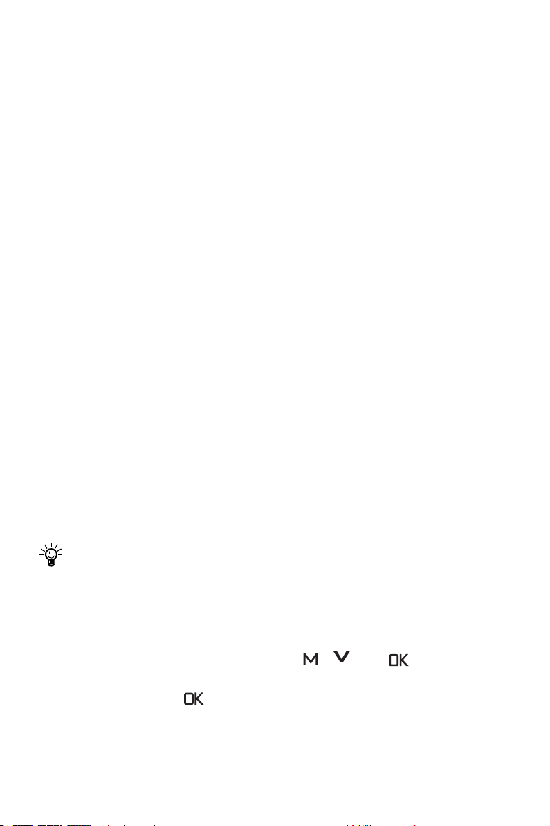
5.7 Rekuperation
Bei Navy Evo Außenbordern kann der Propeller von der Wasserströmung angetrieben
werden. Dadurch wird die Batterie aufgeladen (Nur bei Batterien der Fa. ePropulsion).
Wenn die folgenden Voraussetzungen erfüllt sind, wird der Rekuperationsmodus aktiviert.
1. Die Rekuperation ist bei den Einstellungen der Evo Steuerungen aktiviert (Standardeinstellung).
2. Die Evo Steuerung bendet sich in der NULL-Position.
3. Der Batteriestand (ePropulsion Batterie) liegt unter 90 %.
4. Wenn das Boot mit einer Fahrgeschwindigkeit von mehr als 6 km/h 4 Sekunden gefahren ist, startet die Rekuperation.
5. Rekuperation ist nur mit ePropulsion Batterien möglich.
6. Bei der Verwendung von E-Serie-Batterien müssen Verbindungskabel angeschlossen werden.
Wenn eine der folgenden Situationen vorkommt, stoppt die Rekuperation:
1. Die Rekuperation ist bei den Einstellungen der Evo Steuerungen deaktiviert.
2. Die Evo Steuerung bendet sich nicht in der NULL-Position. (Vorwärts-Fahrt oder
Rückwärts-Fahrt).
3. Das Boot bewegt sich nicht oder die Fahrgeschwindigkeit ist zu hoch (Bei Navy 3.0
Evo mehr als 30 km/h oder bei Navy 6.0 Evo mehr als 30 km/h).
4. Der Batteriestand liegt über 90 %.
Bei Fremdbatterien ist die Rekuperation nicht möglich.
Einstellung der Rekuperation
Bei einer bestehenden Verbindung zwischen der Evo Steuerung und dem Antrieb sowie im eingeschalteten Zustand sowohl der Evo Fernsteuerung als auch des Motors
kann durch gleichzeitiges Drücken der Tasten „ “, „^“ und „ “ in die Einstellungen der Rekuperation gewechselt werden. Anschließend kann der Status der Rekupe-
ration durch Drücken der „ “ Taste geändert werden. „En“ steht für „Aktiviert“. „Dis“
steht für „Deaktiviert“.
94
Page 97
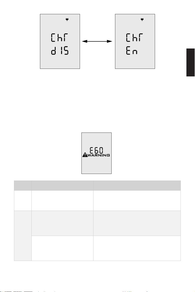
Abb. 5-13
5.8 Warnmeldungen
Bei fehlerhaftem Betrieb oder Störungen des Außenborders erscheinen Fehlercodes
auf dem Display als Warnmeldungen. Gleichzeitig gibt die Evo Fernsteuerung einen
anhaltenden Piepton aus. Die nachfolgende Tabelle hilft Ihnen, Maßnahmen für die
Fehlerbehebung zu nden. Abbildung 5-14 dient nur als Beispiel. Weitere Fehlercodes
und Maßnahmen zur Fehlerbehebung entnehmen Sie der nachfolgenden Tabelle.
Abb. 5-14
Codes Ursachen Maßnahmen
E01
E02
Batteriespannung liegt außerhalb des zulässigen Betriebsbereichs
Der Propeller wurde blockiert
und der Strom des Antriebs
ist zu hoch
Störungen des Antriebs durch
Überstrom verursacht
Die Batterie nach den Betriebsvorgaben
wechseln.
Siehe Maßnahmen zu E10.
Den Hauptschalter ausschalten und 10
Sekunden warten. Den Schalter wieder
einschalten.
Deutsch
95
Page 98

Codes Ursachen Maßnahmen
Auch wenn diese Warnmeldung nicht mehr
E06 Batteriespannung zu gering
Der Propeller ist blockiert und
E10
E11 Übertemperatur des Motors
E12 Übertemperatur der Platine
E22
E30
E56
E60
der Motor wurde dadurch
gestoppt
Interne MCU-Verbindung gestört
Der Positionsgeber des
Gashebels ist fehlerhaft. Der
Hebel muss neu kalibriert
werden
Die Verbindung zwischen Motor und Batterie ist fehlerhaft
Batteriestand der Evo Fernsteuerung reicht nicht aus
erscheint, ist die Leistung des Außenborders womöglich zu niedrig. Die Batterie
muss dringend geladen werden.
Den Hauptschalter ausschalten. Den
Propeller von Fremdkörpern befreien. Den
Propeller mit der Hand drehen. Falls er sich
frei bewegen lässt, kann der Außenborder
wieder eingeschaltet werden.
Den Außenborder ausschalten und abwarten, bis die Temperatur wieder in den
Normalbereich sinkt.
Den Außenborder ausschalten und abwarten, bis die Temperatur wieder in den
Normalbereich sinkt.
Neustart durchführen und prüfen, ob der
Fehler weiter besteht.
Falls ja, kontaktieren Sie bitte Ihren zuständigen ePropulsion Vertragshändler.
Die Vorgehensweise der Kalibrierung entnehmen Sie bitte dem Kapitel 5.3.2 „Kalibrieren“.
Überprüfen, ob das Verbindungskabel
zwischen dem Motor und der ePropulsion
Batterie richtig angeschlossen ist. Falls ja,
Neustart durchführen.
Mit einem Verbindungskabel die Evo Fernsteuerung mit dem Außenborder verbinden.
Siehe hierzu das Kapitel 5.2.2 „Laden über
Ladekabel“.
96
Page 99
Codes Ursachen Maßnahmen
Anzeige
aller
Zeichen
Die Stromversorgung des
Außenborders ist fehlerhaft
Nicht registriert
Falls der Fehler weiterhin besteht, kontaktieren Sie bitte Ihren zuständigen
ePropulsion Vertragshändler.
Die Batterie mit dem Außenborder verbinden. Danach den Hauptschalter einschalten.
Siehe Kapitel 5.6 „Registrierung der Evo
Fernsteuerung im Außenborder“. Die Evo
Fernsteuerung erneut im Außenborder
registrieren.
Deutsch
97
Page 100
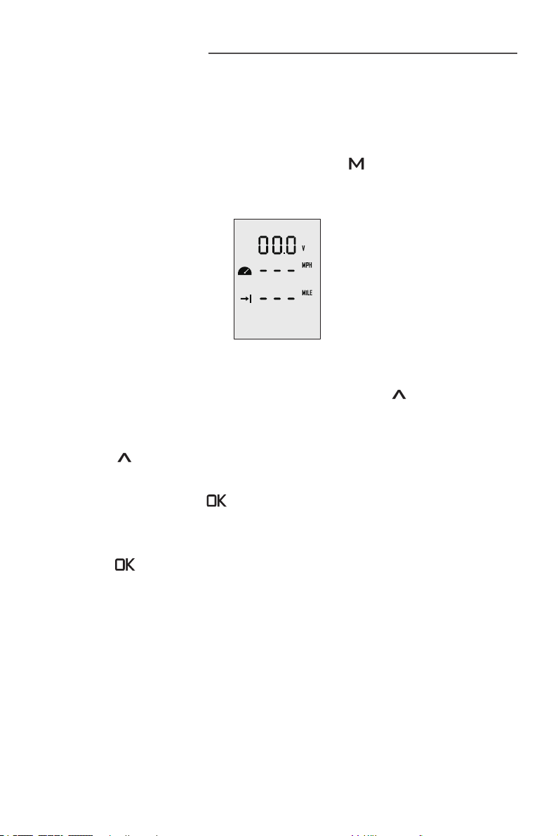
6 Konguration
6.1 Benutzerdenierte Einstellungen
Bevor Sie Ihren Navy Evo Außenborder in Betrieb nehmen, sollten Sie die benutzerde-
nierten Einstellungen wie nachfolgend beschrieben vornehmen.
Schritt 1: Im eingeschalteten Zustand drücken Sie die „ “ Taste ca. 2 Sekunden, um
zu den benutzerdenierten Einstellungen zu gelangen (siehe Abb. 6-1). Der Benutzer
kann nach seinen Vorlieben die Anzeigeoptionen auswählen.
Abb. 6-1
Schritt 2: Im Menü der benutzerdefinierten Einstellungen wird die momentan einzustellende Option blinkend dargestellt. Durch Drücken der „
die anderen Optionen dieser Einstellung sehen. Beispiel: Wenn in Abb. 6-1 „V“ blinkt,
bedeutet es, dass Sie an dieser Stelle andere Optionen auswählen können. Durch
Drücken der „
Spannung wird der Batteriestand angezeigt.
Schritt 3: Durch Drücken der „ “ Taste wird die ausgewählte Option abgespeichert.
Die nächste Einstellung wird automatisch angewählt.
Schritt 4: Nachdem alle Einstellungen vorgenommen sind, können Sie durch langes
Drücken der „ “ Taste die Einstellungen speichern und zum Hauptmenü zurückkehren.
“ Taste wird die Anzeige von „V“ auf „%“ gewechselt. D. h. anstatt der
“ Taste können Sie
98
 Loading...