

Page 1
EnglishDeutsch
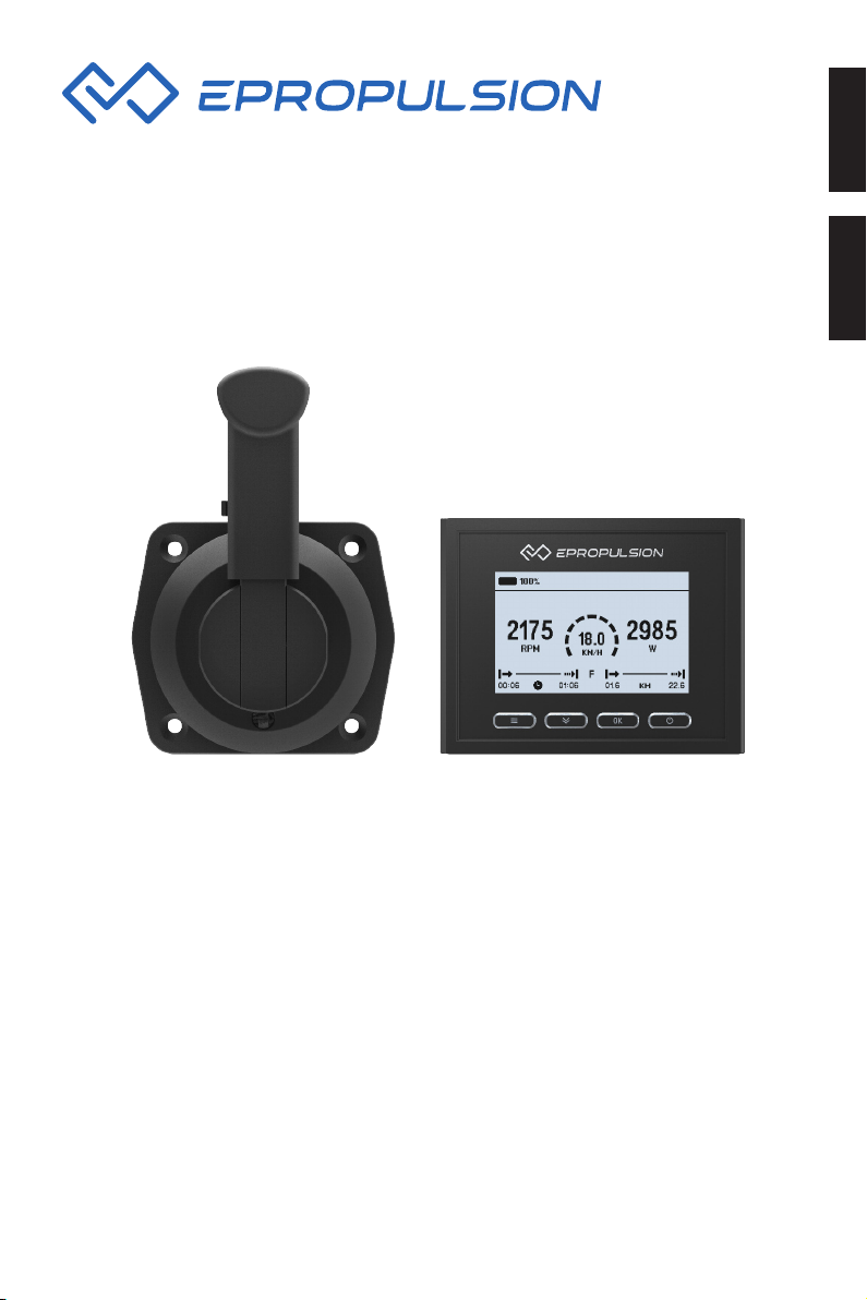
Evo Side Mount Control User Manual
Evo seitliche Fernsteuerung Bedienungsanleitung
2021.08 Version 1.2
Copyright © 2021 ePropulsion. All Rights Reserved
Page 2

Page 3

Acknowledgement
Thanks for choosing ePropulsion products, your trust and support in our company
are sincerely appreciated. We are dedicated to providing high-performance electric
outboards, pod drives, as well as thrusters, reliable lithium batteries and accessories.
Welcome to visit www.epropulsion.com and contact us if you have any concerns.
Using This Manual
Before the use of the product, please read this user manual thoroughly to understand
the correct and safe operations. By using this product, you hereby agree that you have
fully read and understood all contents of this manual. ePropulsion accepts no liability
for any damage or injury caused by operations that contradict this manual.
Due to ongoing optimization of our products, ePropulsion reserves the rights of constantly adjusting the contents described in the manual. ePropulsion also reserves the
intellectual property rights and industrial property rights including copyrights, patents,
logos and designs, etc.
This manual is subject to update without prior notice, please visit our website www.
epropulsion.com for the latest version. If you find any discrepancy between your
products and this manual, or should you have any doubts concerning the product or
the manual, please visit www.epropulsion.com.
ePropulsion reserves the rights of nal interpretation of this manual.
This manual is multilingual, in case of any discrepancy in the interpretation of different language versions, the English version shall prevail.
English
Symbols
The following symbols will help to acquire some key information.
Important instructions or warnings
Useful information or tips
1
Page 4
Product Identification
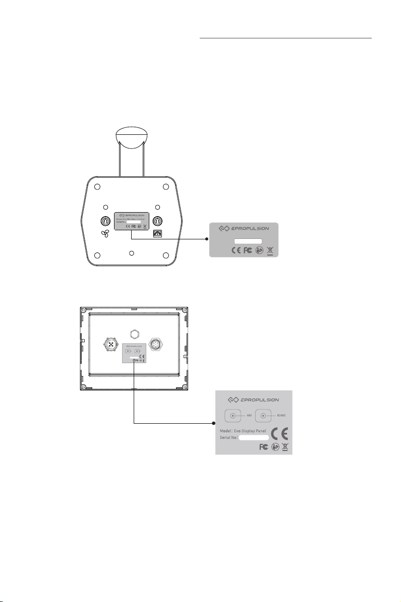
Below picture indicates the serial numbers of Evo Side Mount Control and Evo Display
Panel. Please note the position of the serial numbers and record them for access to
warranty services and other after-sales services. Do not remove or alter the identication label, otherwise the product warranty will be invalid.
Model: Evo Side Mount Control
Serial No.:
Figure 0-1
Model: Evo Display Panel
Serial No:
48V RS485
Figure 0-2
2
Page 5

Table of Contents
Acknowledgement ..................................................................................... 1
Using This Manual ..................................................................................... 1
Symbols .................................................................................................... 1
Product Identification ................................................................................ 2
1 Product Overview ................................................................................... 5
1.1 In the Package ......................................................................................... 5
1.2 Specification ............................................................................................ 7
1.3 Important Notes ...................................................................................... 7
1.4 Declaration ............................................................................................... 8
2 Mounting ................................................................................................ 9
2.1 Mounting the Throttle.............................................................................. 9
2.1.1 Mounting from the back side ........................................................ 9
2.1.2 Mounting from the front side ...................................................... 10
2.2 Mounting the Display Panel .................................................................. 11
2.3 Connection ............................................................................................. 13
2.4 Version Setting ......................................................................................14
2.5 Port or Starboard Side Setting .............................................................. 15
English
3 Features of Components ....................................................................... 17
3.1 Detachable Throttle ............................................................................... 17
3.1.1 Detach the Handle ....................................................................... 17
3.1.2 Install the Handle ......................................................................... 17
3.2 Display Panel ......................................................................................... 18
4 Operation Guide .................................................................................... 21
4.1 System Settings ..................................................................................... 21
4.1.1 Version Setting .............................................................................21
4.1.2 Power Limited Setting ................................................................. 22
4.1.3 Preference Settings ..................................................................... 23
4.1.4 Battery Configuration .................................................................. 24
4.2 Throttle Operation ................................................................................. 28
4.2.1 Power Adjusting ........................................................................... 28
3
Page 6

4.2.2 Recalibration ................................................................................ 29
4.3 Use of Kill Switch ................................................................................... 31
4.4 Checklist before Use ............................................................................. 32
4.5 Starting the Motor ................................................................................. 33
4.6 Stopping the Motor................................................................................34
5 Warning Messages ............................................................................... 35
6 Warranty .............................................................................................. 41
6.1 Warranty Policies ...................................................................................41
6.2 Out of Warranty ......................................................................................42
6.3 Warranty Claim Procedures .................................................................. 42
4
Page 7
1 Product Overview
Evo Side Mount Control is a wired throttle control handle with a display panel. It is
compatible with ePropulsion outboards and pod drives.
1.1 In the Package
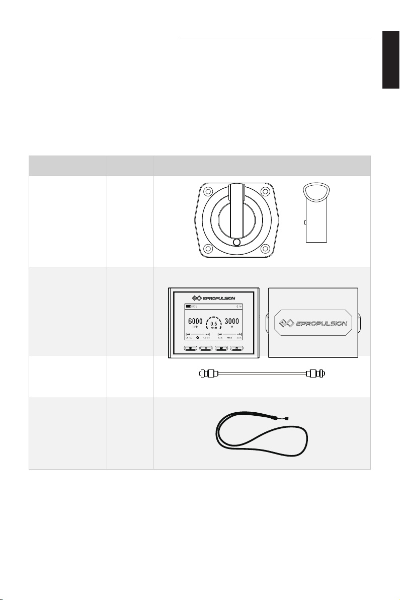
When you receive a set of Evo Side Mount Control, unpack its package and check if
all the items below are included in the package. If there is any loss or transport damage, please contact your dealer immediately.
Item Oty./Unit Figure
Throttle 1 Set
Evo Display Panel
(w/ protection
cover)
1 Set
English
Communication
Cable 0.5m
Kill Switch 2 Sets
1 Set
0.5m
5
Page 8
Item Oty./Unit Figure
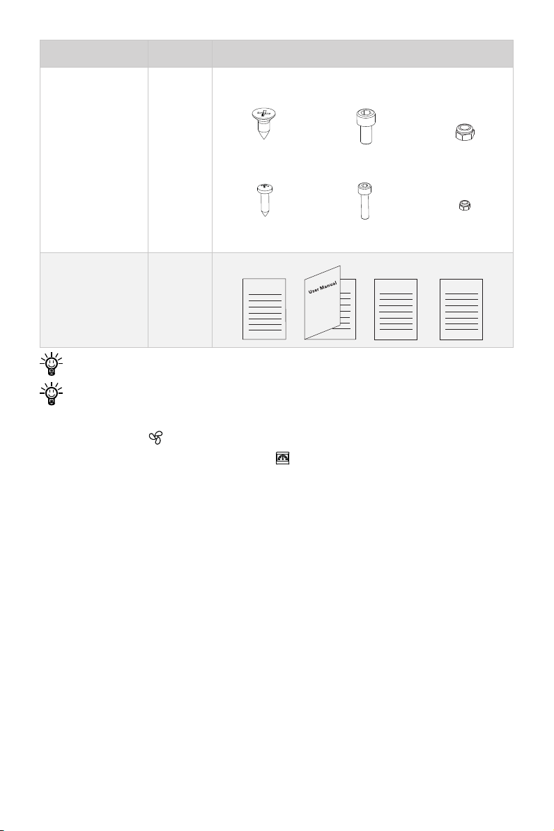
Screws and Nuts 1 Set
×4
M6X16
×4
M3X16
M6X16
M3X16
×4
M6
×4
M3
User Manual, Warranty Card, Quick
Start & Fixing
Warranty
1 Set
Fixing Guide Quick Start
Guide
Save ePropulsion original package for transport and storage.
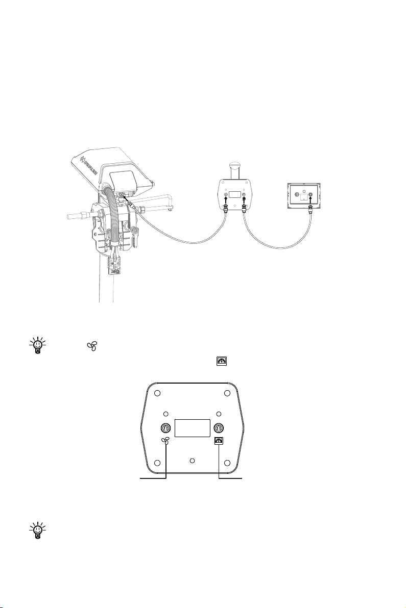
Be attention to distinguish the communication ports in the Evo Side Mount Control. Please using a communication cable to connect the motor to the connector
with the sign " " and use another communication cable to connect the display
panel to the connector with the sign " ".
×4
×4
6
Page 9

1.2 Specification
Evo Side Mount Control
Weight 0.9 kg
Display 4.3" Independent Display
Communication Wired
Communication Distance ≤ 15 m
English
Dimensions
117 x 160.3 x 53.6 mm (Throttle)
138.5 x 106.9 x 42.5 mm (Display)
1.3 Important Notes
1. Check the status of the Evo Side Mount Control and battery level before each trip.
2. Only adults who have fully read and understood this manual are allowed to
operate this product.
3. Make sure the Evo Side Mount Control is properly installed before use.
4. Be familiar with the basic operation of this product before use, including start-up,
stop, control mode, and emergency stop.
5. Make sure that the function of this product is normal before each use.
6. Stop the motor immediately if someone falls overboard during the trip.
7. When using NAVY outboards/Pod Drive 3.0 Evo/Pod Drive 6.0 Evo, the distance
and speed value displayed is measured by Global Positioning System (GPS), there
may exist small errors due to GPS signal strength degradation or some external
environment conditions like currents, winds and change of course.
7
Page 10

1.4 Declaration
Object of the declaration:
Product Description: Evo Side Mount Control
Model: Evo Side Mount Control
Company Name: Guangdong ePropulsion Technology Limited
Company Address: Room 201, Bldg.17A, 4th XinZhu Road, SongShan Lake District,
Dongguan City, Guangdong Province, China
The object of the declaration is in conformity with the following directives:
EMC-directive 2014/30/EU
Applied standards:
EN 55014-1:2017
EN 55014-2:2015
EN 61000-3-2:2014
EN 61000-3-3:2013
This device complies with part 15 of the FCC Rules: Operation is subject to the
following two conditions:
(1) This device may not cause harmful interference and,
(2) This device must accept any interference received, including
interference that may cause undesired operation.
Signature:
Shizheng Tao, Chief Executive Officer & Cofounder of
Guangdong ePropulsion Technology Limited
8
Page 11
2 Mounting
60
6
28
25
30
First mount the Evo Side Mount Control including the throttle and the display panel,
then connect to the motor and the battery with communication cables, and congure
the version and the handle side.
Before mounting the Evo Side Mount Control, it is recommended to connect the
entire equipment rst, check whether it works well, and whether the communication cable is properly connected. For the connection method of the communication cable, please refer to 2.3 Connection.
Make sure the proposed location reserves enough room for operating and will
allow rotating the throttle without hitting obstructions.
When selecting the mounting location, examine your boat to ensure that you will
not drill into any obstructions and the throttle will be accessible for assembly,
the cables will be accessible for connection.
2.1 Mounting the Throttle
Follow the instructions below to x the throttle of the Evo Side Mount Control to the
boat. It can be mounted from the back side or front side.
2.1.1 Mounting from the back side
English
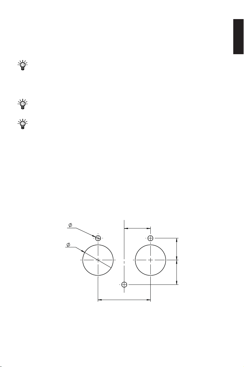
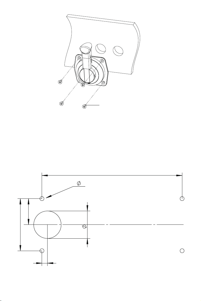
1. Drill holes on the hull through the xing guide referring to the gure 2-1.
35
Figure 2-1
9
Page 12
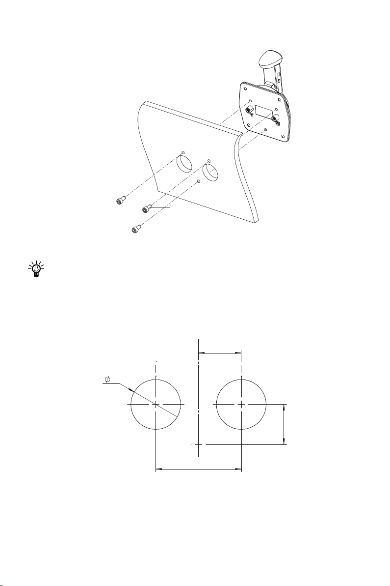
2. Fix the throttle to the side of the boat referring to the gure 2-2.
60
28
30
M6 Screw
Figure 2-2
If a panel board thickness is between 2mm (0.08 in.) and 8mm (0.31 in.), please
use the supplied screws. If not, please purchase suitable screws separately.
2.1.2 Mounting from the front side
1. Drill holes on the hull through the xing guide referring to the gure 2-3.
35
Figure 2-3
10
Page 13
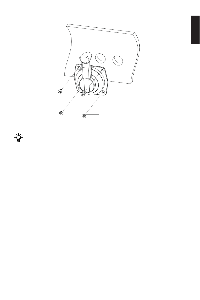
2. Fix the throttle to the side of the boat referring to the gure 2-4.
M6 Tapping Screw
Figure 2-4
If a panel board thickness is between 2mm (0.08 in.) and 8mm (0.31 in.), please
use the supplied screws. If not, please purchase suitable screws separately.
2.2 Mounting the Display Panel
English
Follow the instructions below to x the display panel of the Evo Side Mount Control to
the boat.
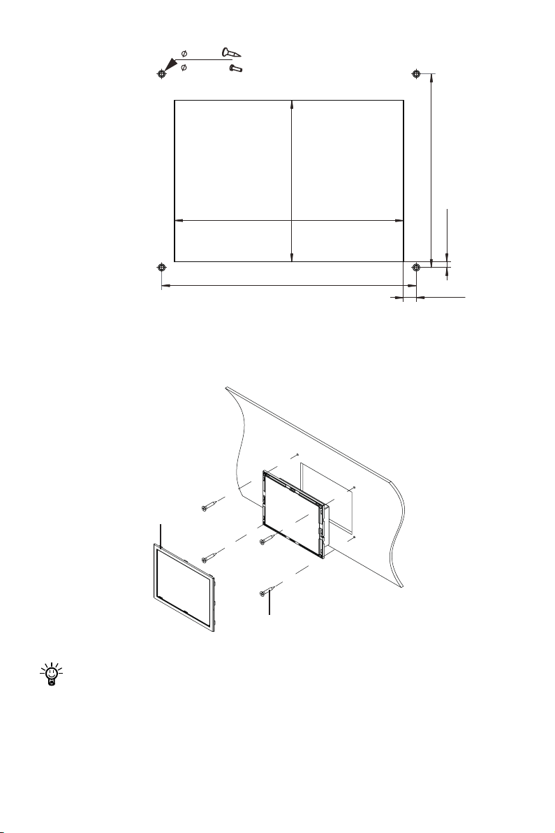
1. Drill holes on the hull through the xing guide referring to the gure 2-5.
11
Page 14
2 X 4
3.5 X 4
82.7
117.5
130.6
Figure 2-5
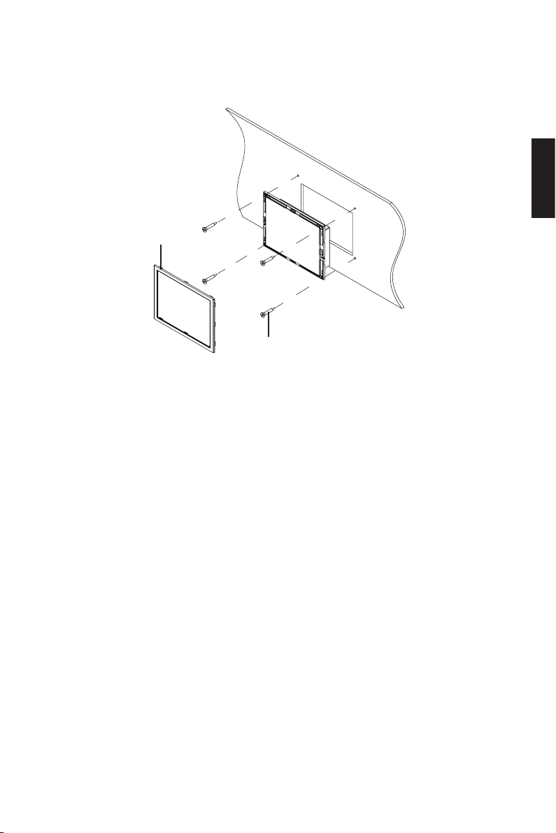
2. Remove the trim.
3. Fix the display panel to the boat referring to the gure 2-6.
99.2
2.9
6.6
Trim
M3 Tapping Screw
Figure 2-6
If a panel board thickness is between 2mm (0.08 in.) and 8mm (0.31 in.), please
use the supplied screws. If not, please purchase suitable screws separately.
12
Page 15
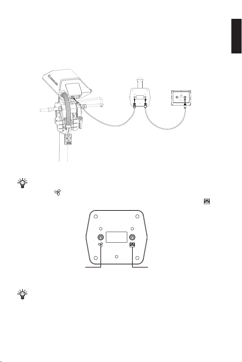
2.3 Connection
Connect to display panelConnect to the motor
The Evo Side Mount Control communicates with the motor via communication cables. Please follow the steps below to complete the connection:
1. Connect the throttle and display panel with a communication cable;
2. Connect the motor to the battery.
Figure 2-7
Please using a communication cable to connect the motor to the connector with
the sign " " on the Evo Side Mount Control and use another communication
cable to connect the display panel to the other connector with the sign " ".
English
Figure 2-8
If the display panel displays “Equipment oine”, please check whether the kill
switch is on the proper position. If the kill switch is attached properly, please refer page 33 to solve the problems.
13
Page 16
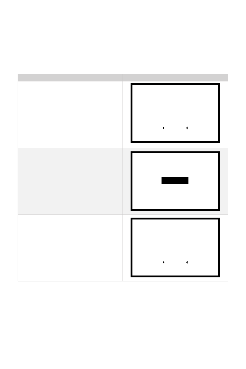
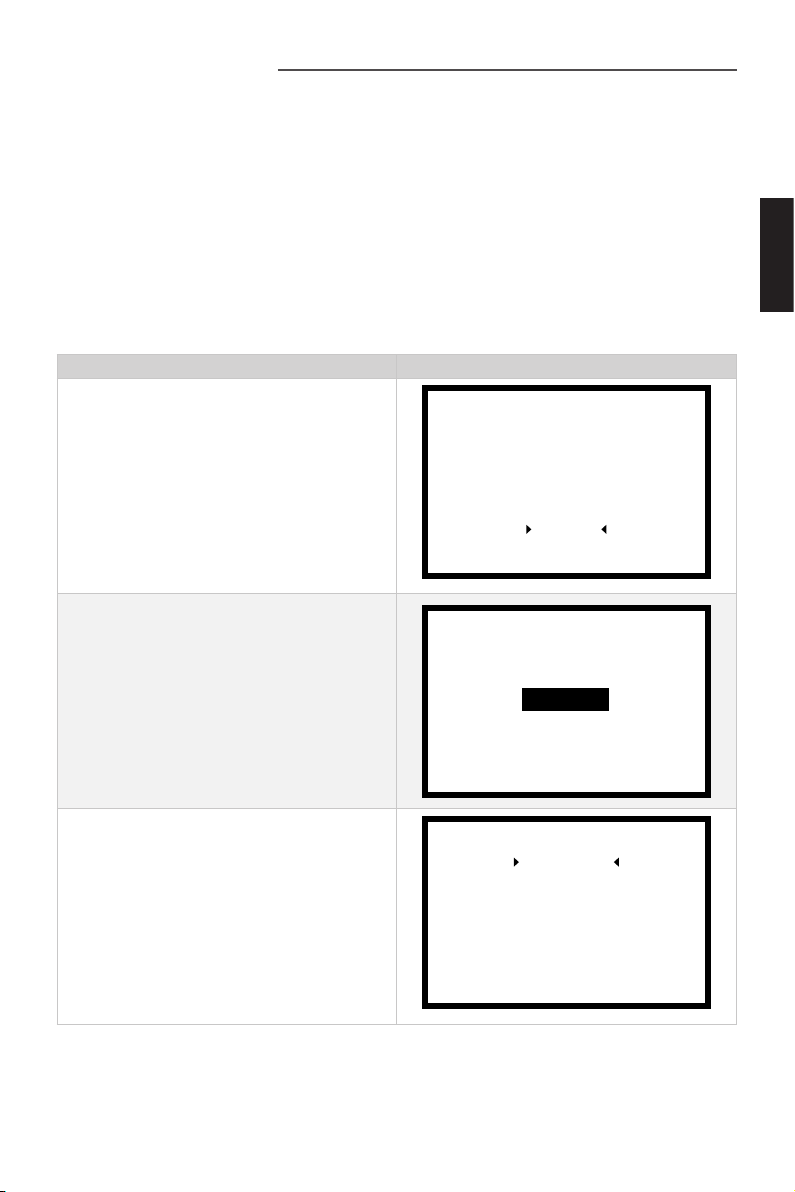
2.4 Version Setting
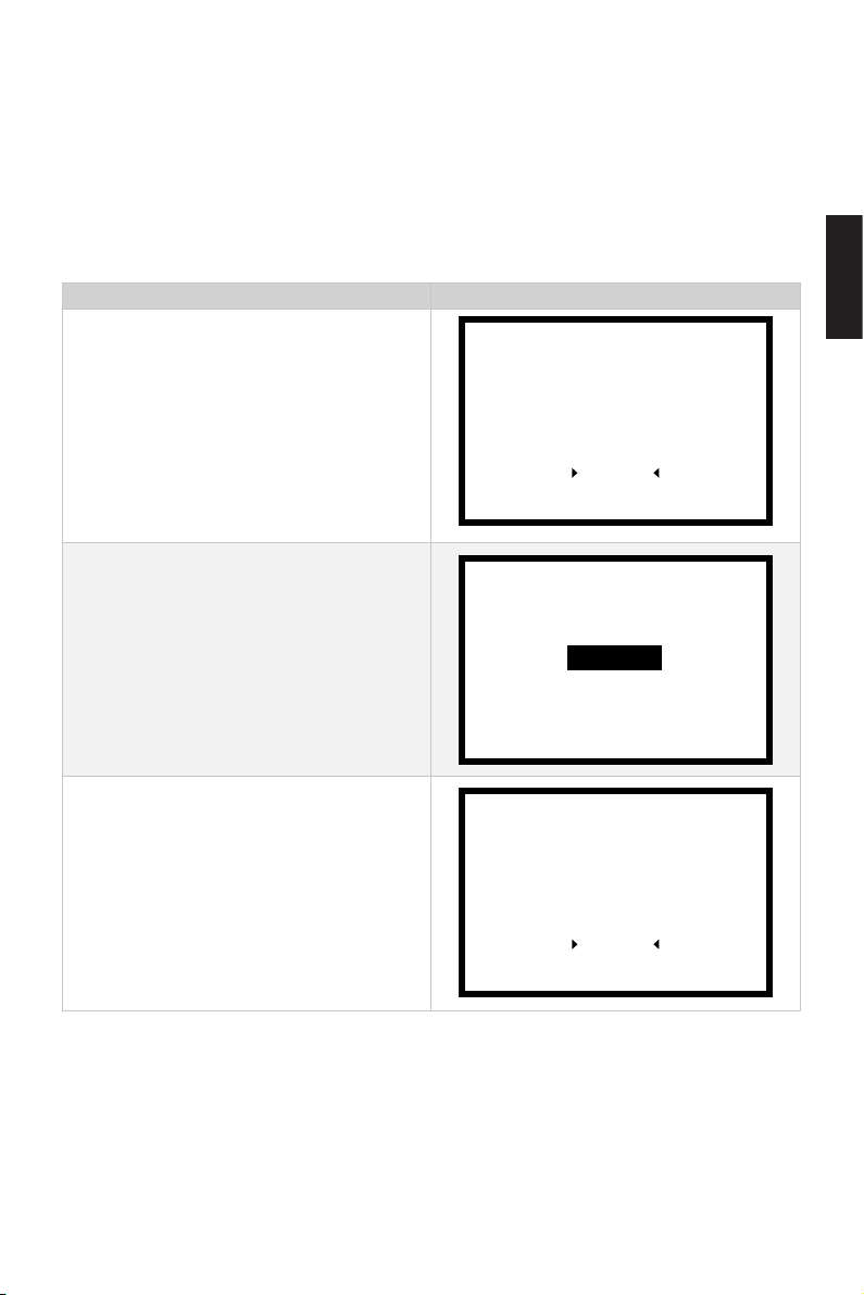
Evo Side Mount Control will automatically be recognized as an Evo version if it is connected with the Evo machine. If connected with other ePropulsion machine, it is Spirit1.0 version by default. If you need to connect to NAVY outboard or Pod Drive, please
switch to a different version according to the following steps:
Version Setting Process LCD Displaying
Step1: In power-on state, long press the
Menu button to enter the preference
setting page. Press the Select button to
switch to "Version" to enter the version
setting page.
Step2: Press the Select button to select
the version
.
Step3: Press the Confirm button to
save the setting. And it will return to
preference setting page automatically.
Power Limit
Unit Setting
Battery Setting
Throttle
Version
Navy 3.0
Navy 6.0
Pod 1.0
Pod 3.0
EVO
Power Limit
Unit Setting
Battery Setting
Throttle
Version
14
Page 17
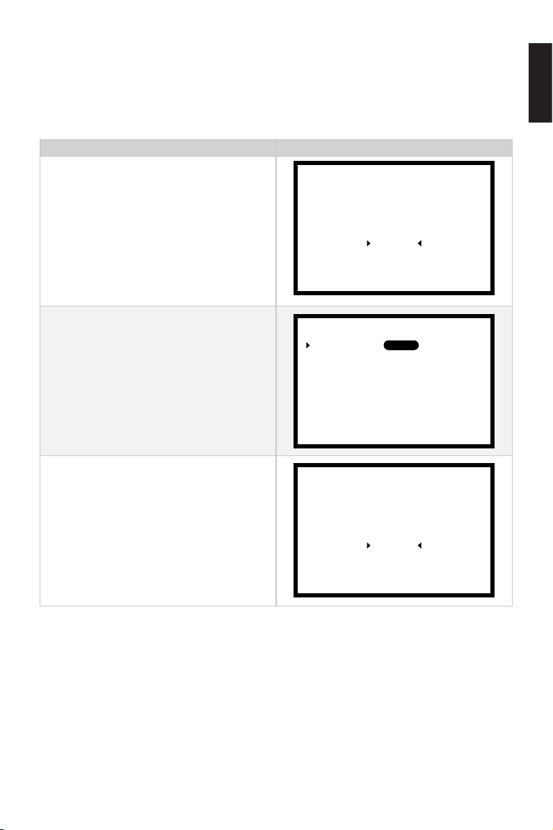
2.5 Port or Starboard Side Setting
Make sure the handle side setting is done correctly before use. The Evo Side Mount
Control is in starboard (right) side mode by default. If you need to switch between the
port (left) or starboard (right) side, please refer to the following process for setting.
Handle Side Setting Process LCD Displaying
English
Step1: In power-on state, long press the
Menu button to enter the preference
setting page. Press the Select button
to switch to "Throttle" and press the
Confirm butoon to enter the Throttle
setting page.
Step2: Press the Confirm button to enter
the Handle Side setting, then press the
Select button to select the port side
or the starboard side. Press Confirm
button to save the setting.
Step3: Press Menu button to return to
preference setting page automatically.
Battery Setting
Handle Side:
Calibration
Battery Setting
Power Limit
Unit Setting
Throttle
Version
STBDPORT
Power Limit
Unit Setting
Throttle
Version
15
Page 18
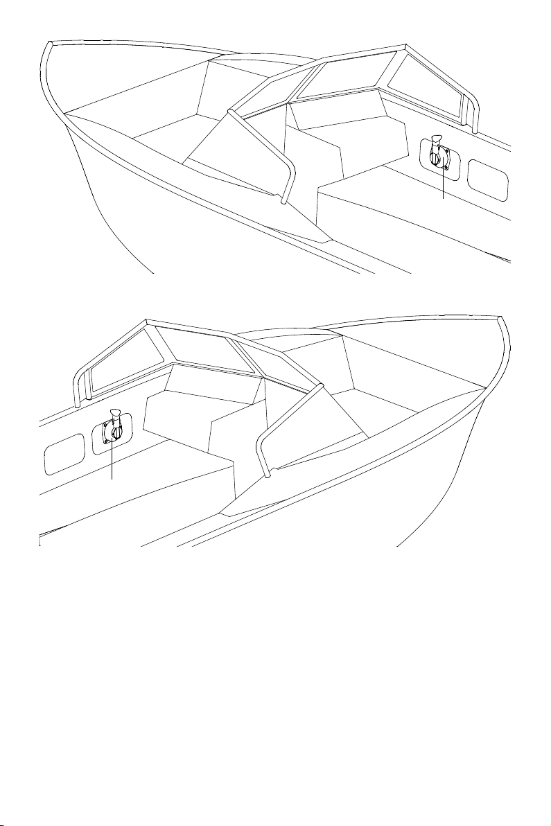
Figure 2-9 Starboard (right) Side
Throttle
Throttle
Figure 2-10 Port (left) Side
16
Page 19
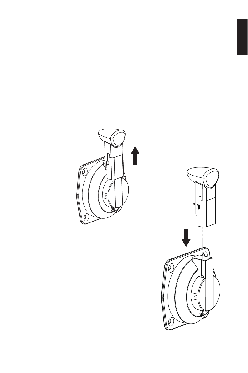
3 Features of Components
The Evo Side Mount Control is connected to the motor by wire, and used for starting
and stopping the motor, adjusting the motor speed, conguring the battery parameters, displaying the system information and messages, etc.
3.1 Detachable Throttle
3.1.1 Detach the Handle
In the original package, the handle of the throttle is an assembly, and it's detachable
to change the length of the handle for easier use. If you need to detach the handle of
the throttle, please press and hold the release button on the handle and then pull the
handle up and out. Refer to the gure below.
Release
Button
Handle
English
Figure 3-1
3.1.2 Install the Handle
If you need to install the handle to the throttle,
please push the handle in the slot to the end then
the release button on the handle is stuck.
Figure 3-2
17
Page 20
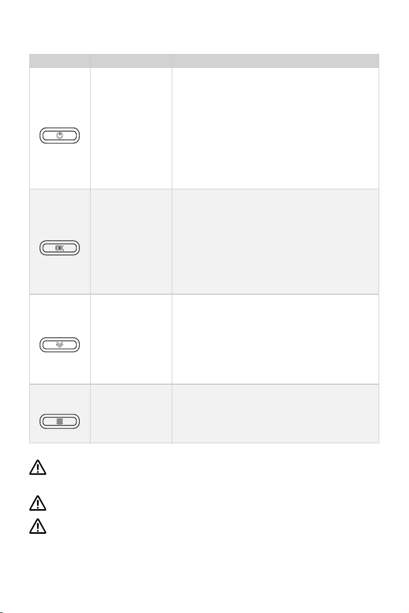
3.2 Display Panel
Buttons Functions
Power button
Conrm button
Select button
Menu
1. When the display panel is turned off, press and
hold the power button to power on the display
panel.
2. When the display panel is turned on, press and
hold the power button to power off the display
panel.
3. When the display panel is turned on, press the
power button to switch on or off the backlight.
1.On the main page, press the Conrm button
to switch the display between battery level or
battery voltage.
2.On setting pages, press the Conrm button to
save the current settings and when setting the
parameters, press Conrm button to switch to
the next item.
1.If connecting with NAVY outboards or Pod Drive 3.0/6.0, on the main page, press Select button
to change the unit of speed and distance.
2.On setting pages, press Select button to view
options for current setting, or adjust conguration parameters.
1. In power-on state, long press the Menu button
to enter the preference setting page.
2. On setting pages, press Menu button to return
to the home page or previous page.
Please attached the kill switch properly before turning on the display panel, otherwise the display panel will display “Equipment offline”.
All operations on the display panel need to be done in power-on state.
If users enter the page without setting any parameters, the current parameters
displayed on the page will be saved as user parameters by default.
18
Page 21
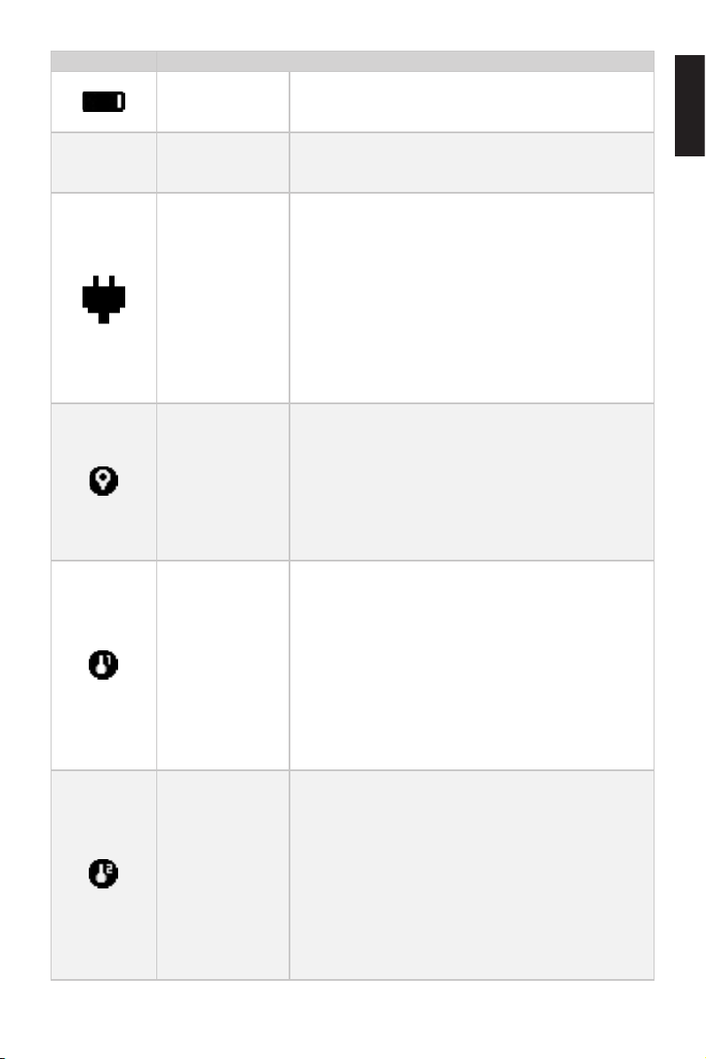
100%
48.0V
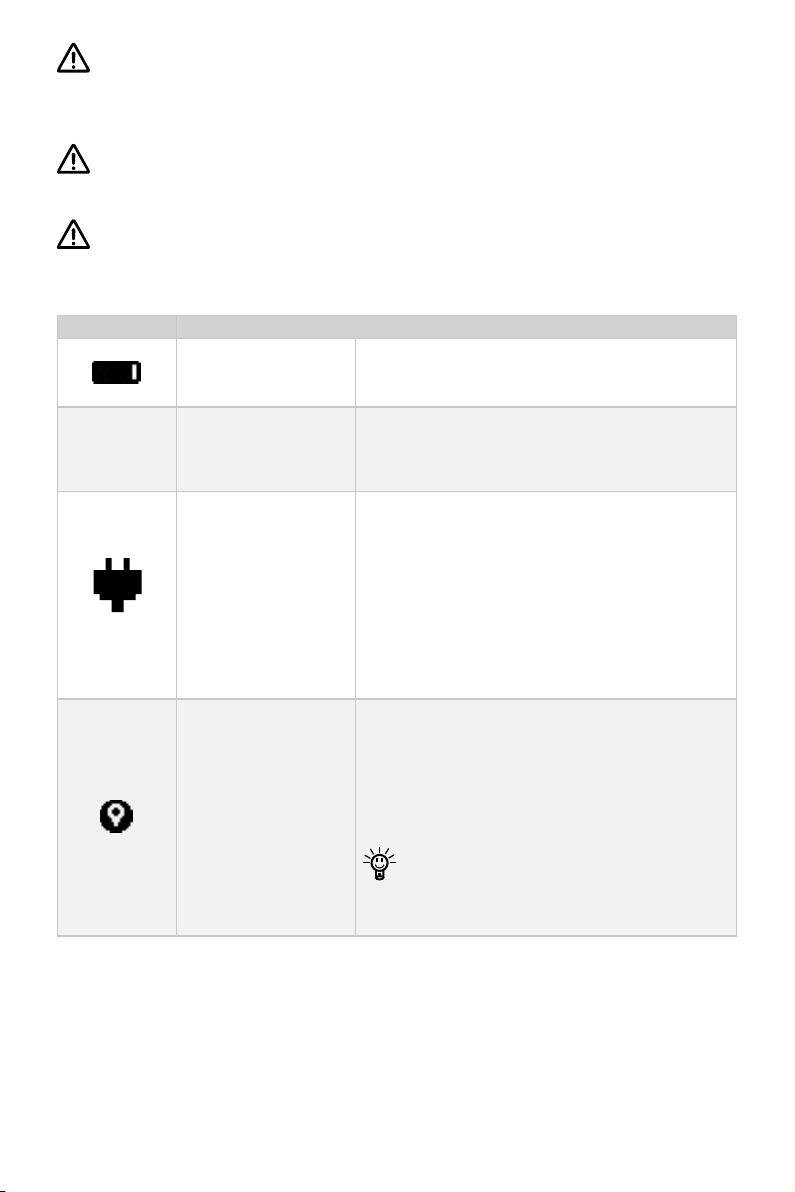
Icons Functions
Battery level
indicator
Battery voltage /
level
Hydrogeneration
indicator
GPS status
indicator
Motor over-heat
alert
Controller over-
heat alert
Indicating battery level.
48.0V : indicates current battery voltage.
100% : indicates current battery level.
The machine can turn on or off the hydro generation function on the perference page if it supported
this function.
Shown constantly: the hydro generation function
is turned on.
Blink: the machine is charging the battery.
Hidden: the hydro generation function is turned
off.
Hidden: no satellite signal is received or GPS does
not work.
Blink: GPS is connecting to satellites.
Shown constantly: GPS is in use.
If connect with SPIRIT 1.0 or Pod Drive 1.0, GPS
status indicator will be always hidden.
Hidden: system temperature is in normal range.
Blink: system temperature is a little high and the
maximum input power of motor has been lowered
than rated maximum power.
Shown constantly: system is over temperature
and the outboard will stop working. The outboard
motor can’t be started until the system temperature drops to a certain level.
Hidden: system temperature is in normal range.
Blink: system temperature is a little high and the
maximum input power of motor has been lowered
than rated maximum power.
Shown constantly: system is over temperature
and the outboard will stop working. The outboard
motor can’t be started until the system temperature drops to a certain level.
19
English
Page 22
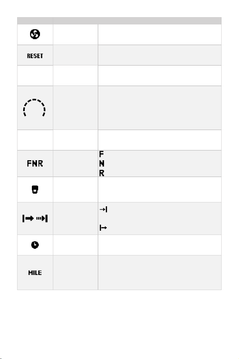
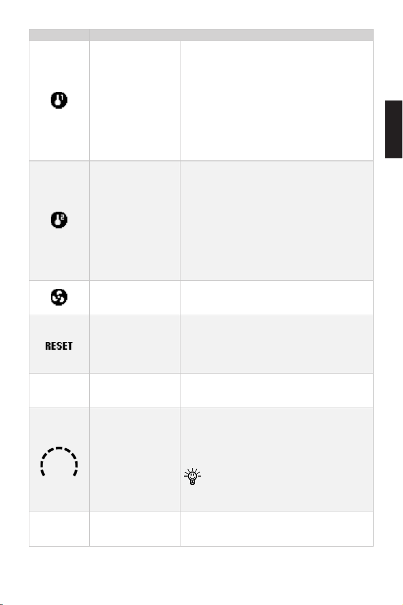
Icons Functions
3000
W
6000
RPM
Fan fault
Hidden: fan works normally.
Blink: fan has faults.
0.5
KM/H
Throttle reset
indicator
A blinking "RESET" indicating the throttle should
be reset to the neutral position.
Throttle Power Displaying real time input power to the system.
Displaying real time cruising speed.
Set units (KM/H, MPH or KNOTS) in preference
Current speed
setting page.
If it is connected with SPIRIT outboards or pod
drive 1.0, it will display the ePropulsion logo.
Ratational speed Displaying real time motor rotational speed.
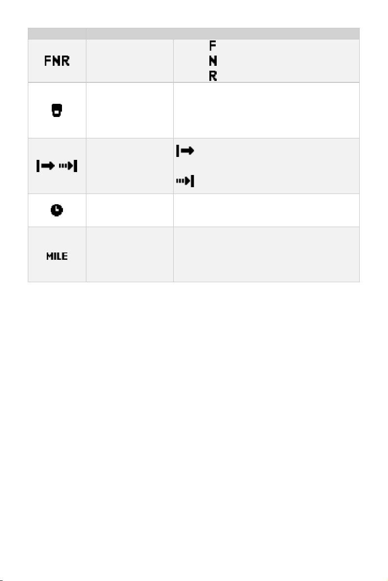
: forward gear
Throttle gear
: neutral gear
: backward gear
Hidden: kill switch is well attached and works
Kill switch status
indicator
well.
Shown constantly: the kill switch is detached.
Travelled
distance/time
or remaining
distance/time
Time
display
: Remaining distance or time that outboard can
travel.
: Travelled distance or time.
Displaying real time travel time.
Displaying remaining distance that outboard can
Distance display
travel or travelled distance
Set units (MILE, KM (kilometer) and NM (nautical
mile)) in preference setting page.
20
Page 23
4 Operation Guide
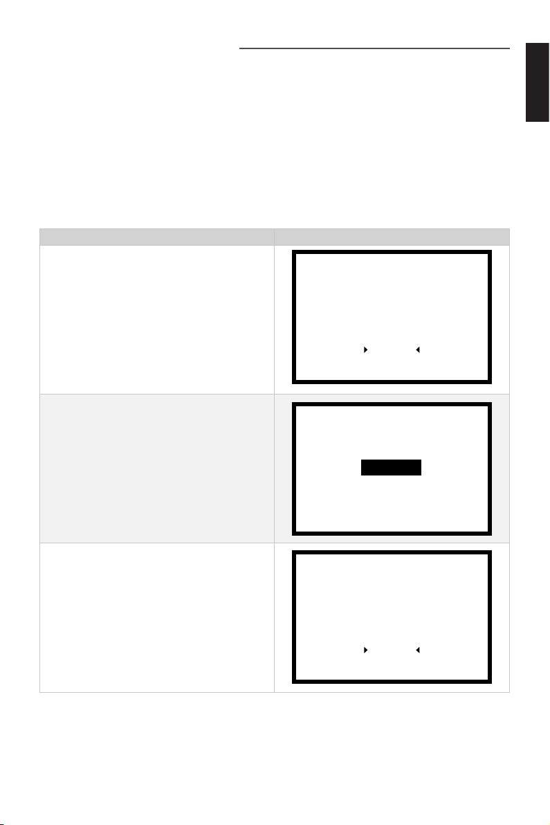
4.1 System Settings
4.1.1 Version Setting
Evo Side Mount Control will automatically be recognized as an Evo version if it is connected with the Evo machine. If connected with other ePropulsion machine, it is Spirit1.0 version by default. If you need to connect to NAVY outboard or Pod Drive, please
switch to a different version according to the following steps:
Version Setting Process LCD Displaying
English
Step1: In power-on state, press the
Menu button and hold for 3s to enter
the preference setting page. Press the
Select button to switch to "Version".
Press the Confirm button to enter
Version Setting page.
Step2: Press the Select button to
choose the version you need.
Step3: Press the Confirm button to
save the setting. And it will return to
preference setting page automatically.
Power Limit
Unit Setting
Battery Setting
Throttle
Version
Navy 3.0
Navy 6.0
Pod 1.0
Pod 3.0
EVO
Power Limit
Unit Setting
Battery Setting
Throttle
Version
21
Page 24
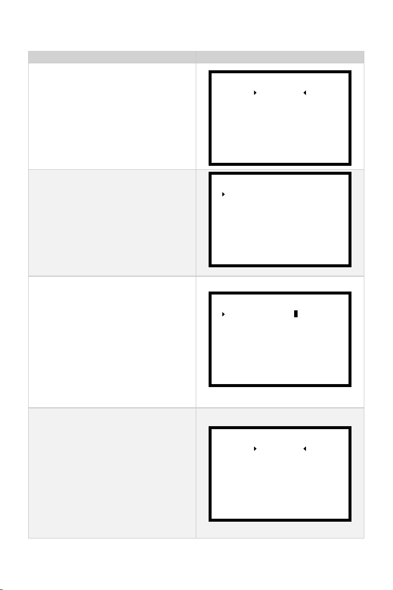
4.1.2 Power Limited Setting
Power Limited Setting Process LCD Displaying
Step1: In power-on state, long press the
Menu button to enter the preference
setting page. When the arrow points to
"PowerLimit", press the Confirm button
to enter the power limit setting page.
Step2: Use the Select button to select
the power you want to set. "Forward" is
the forward power and "Backward" is
the backward power. Press the Confirm
button to enter this power limit option.
Step3: Please set the three-digit value
from left to right through the Select button. Each time you set a value, press the
Confirm button to move to the next digit.
The ashing value is the value being
edited.
The power is limited to 1%-100%. The
backward power of NAVY 6.0 is limited
to 1%-50%.
Step 4: After setting all the values of
the forward power limit, press the menu
button to return, and press the select button to select the backward power limit
option. After the forward and backward
power limits are set, press the Menu
button to return to the preference setting
page, and the setting parameters are
automatically saved.
Power Limit
Unit Setting
Battery Setting
Throttle
Version
Forward Limit:
Backward Limit:
Forward Limit:
Backward Limit: 001 %
Battery Setting
001 %
001 %
001 %
Power Limit
Unit Setting
Throttle
Version
22
Page 25
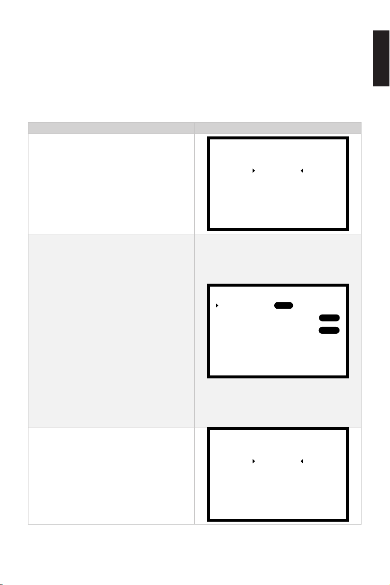
4.1.3 Preference Settings
The following speed unit settings and mileage unit settings need to be valid when
connected to NAVY machines and pod drive 3.0 or 6.0. Please make sure that the Evo
side throttle lever is at Evo, Navy3.0, Navy6.0 or Pod3.0 before setting. It is recommended to follow the steps below to set the display preferences before using the Evo
Side Mount Control.
Preference Settings Process LCD Displaying
English
Step1: In power-on state, long press the
Menu button to enter the preference
setting page. Press the Select button
to switch to "UnitSetting".Press the
Confirm button to enter the unit setting
page.
Step2: Press the Confirm button to enter
one of the unit setting pages. Press the
Select button to choose the unit you
want to display.
"Battery" is the battery power and
voltage display selection. "Distance
Unit" is the choice of distance unit;
"Speed Unit" is the choice of speed unit.
Through the Select button, select the
unit to be displayed, and press the
Confirm button to confirm. White text on
a black background is selected. Press
the Menu button to return to previous
setting page.
Power Limit
Unit Setting
Battery Setting
Throttle
Version
Battery:
Speed Unit:
Distance Unit:
SOC
KNOTS
NM
Volt
MPH
MILE
KM/H
KM
Step3: Press the Menu button to return
to preference setting page.
Power Limit
Unit Setting
Battery Setting
Throttle
Version
23
Page 26
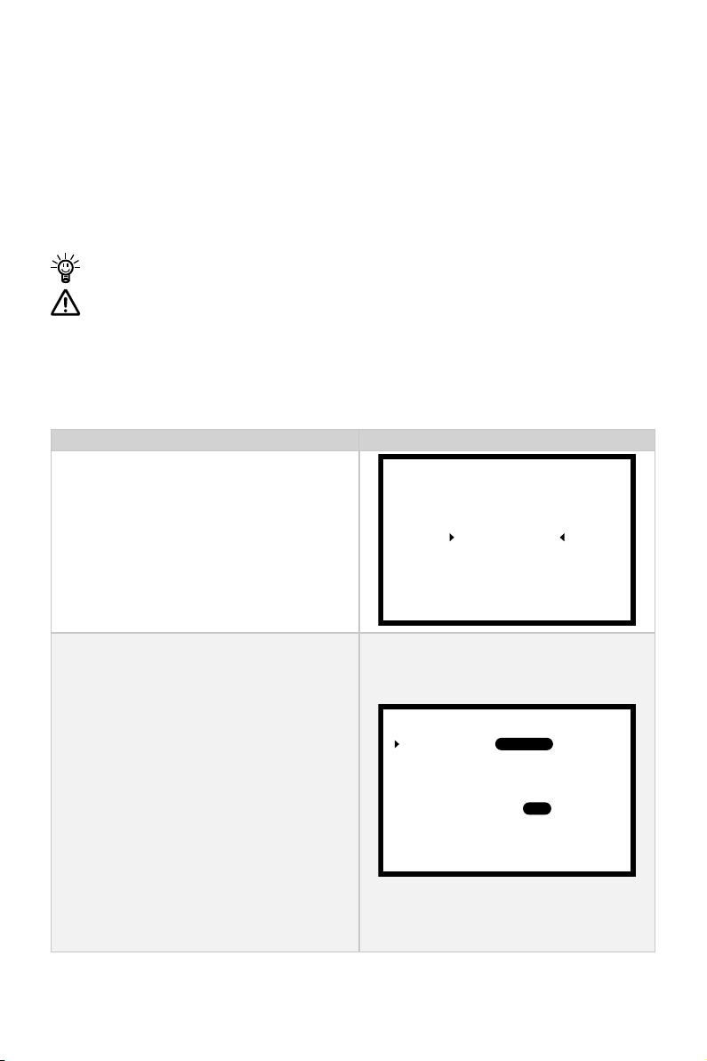
4.1.4 Battery Configuration
Accurate battery conguration helps achieve precise estimation of the battery’s discharging state. When using an ePropulsion Battery and all the communication cables
are well connected, the battery conguration is self-congured and the hydrogeneration function can be switched on or off. When not using ePropulsion Batteries, users
should manually congure the batteries via Evo Side Mount Control at the rst time
use, so the battery level will display more accurate.
When using ePropulsion SPIRIT battery, it does not need to congure the battery.
Battery conguration should be carried out if a battery with different type/capac-
ity/voltage is connected to motor for the rst time. There are some calculation
errors in battery level display. Please plan the journey, reserve more than 15%
of the endurance power to avoid midway power exhaustion, or prepare enough
spare batteries.
Battery Setting Process LCD Displaying
Step1: In power-on state, long press the
Menu button to enter the preference
setting page. Press the Select button
to switch to "BatterySetting". Press
the Confirm button to enter the battery
setting page.
Step2: When the arrow points to "Type",
then press the Confirm button, and
choose the battery type according to the
battery you use. Press the Select button
to switch the battery type options between Li-ion, LiFePO4 and Lead acid.
Li-ion: lithium-ion battery
LiFePO4: Lithium-ion ferrous phosphate
battery
Lead acid: Lead-acid battery
Press the Conrm button to save the setting for the current item.
Power Limit
Unit Setting
Battery Setting
Throttle
Version
Type:
Capacity:
Voltage Rating:
Hydrogeneration:
Undervolt Value:
0010 Ah
30.0 V
ON
30.0 V
Lead-acidLi-ion LiFePO4
OFF
24
Page 27
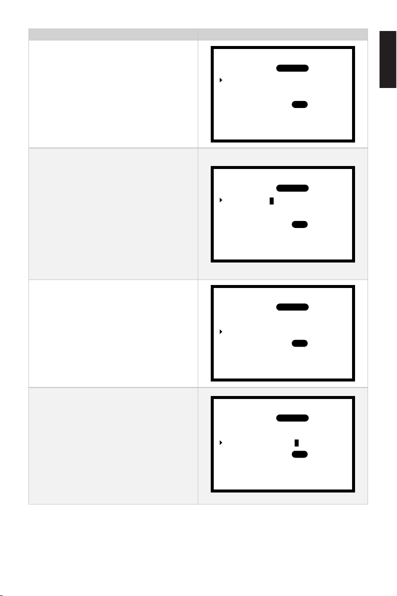
Battery Setting Process LCD Displaying
Step3: Press the Menu button to return
to previous setting page, and press the
Select button to switch to "Capacity".
Step 4: Press the Confirm button to
set the battery capacity setting. Please
set the three-digit value through the
Select buttons from left to right. After
each value is set, press the Confirm
button to move to the next value. The
flashing value is the value being edited.
The battery capacity setting range is
1-9999Ah.
Step5: Press the Menu button to return
to previous setting page, and press the
Select button to switch to "Voltage rating".
Type:
Capacity:
Voltage Rating:
Hydrogeneration:
Undervolt Value:
Type:
Capacity:
Voltage Rating:
Hydrogeneration:
Undervolt Value:
Type:
Capacity:
Voltage Rating:
Hydrogeneration:
Undervolt Value:
0010 Ah
0010 Ah
0010 Ah
30.0 V
ON
30.0 V
30.0 V
ON
30.0 V
30.0 V
ON
30.0 V
Lead-acidLi-ion LiFePO4
English
OFF
Lead-acidLi-ion LiFePO4
OFF
Lead-acidLi-ion LiFePO4
OFF
Step 6: Press the Confirm button to set
the rated voltage. Please set the threedigit value through the selection buttons
from left to right. After each value is set,
press the Confirm button to move to the
next value. The flashing value is the value
being edited. The battery rated voltage
setting range is 30-99.9V.
25
Type:
Capacity:
Voltage Rating:
Hydrogeneration:
Undervolt Value:
0010 Ah
30.0 V
ON
30.0 V
Lead-acidLi-ion LiFePO4
OFF
Page 28
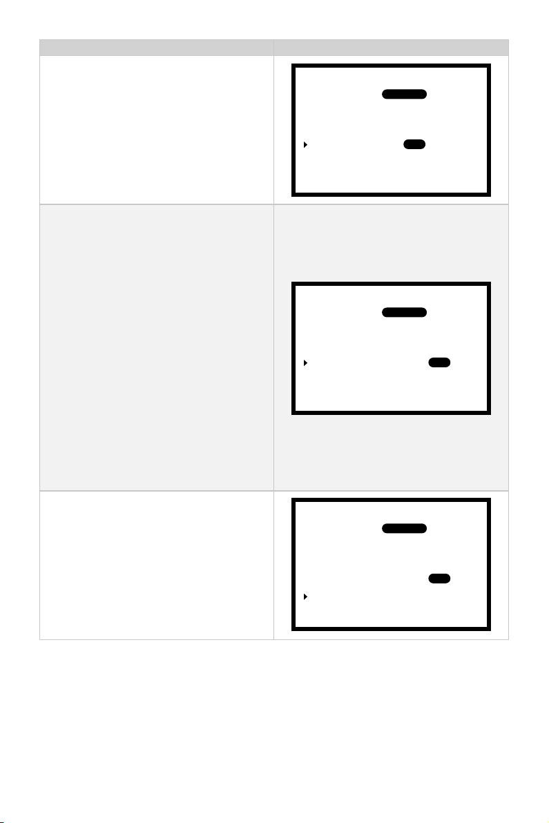
Battery Setting Process LCD Displaying
Step 7: Press the menu button to return,
and press the select button, so that the
arrow points to "Hydrogeneration".
Step 8: Press the Confirm button to set
the hydro generation function, Press
the selection button to switch between
"ON, OFF", "ON" to turn on the hydro
generation function, models that support
the hydro generation function can be
turned on, and "OFF" is turn off the hydro
generation function.
If it is connected to a machine that does
not support hydro generation function or
the machine is not connected with the
battery by a communication cable, the
hydro generation function is turned off by
default.
Type:
Capacity:
Voltage Rating:
Hydrogeneration:
Undervolt Value:
Type:
Capacity:
Voltage Rating:
Hydrogeneration:
Undervolt Value: 30.0 V
0010 Ah
30.0 V
ON
30.0 V
0010 Ah
30.0 V
ON
Lead-acidLi-ion LiFePO4
OFF
Lead-acidLi-ion LiFePO4
OFF
Step 9: Press the menu button to return,
and press the Select button, so that the
arrow points to "Undervolt Value".
26
Type:
Capacity:
Voltage Rating:
Hydrogeneration:
Undervolt Value: 30.0 V
0010 Ah
30.0 V
ON
Lead-acidLi-ion LiFePO4
OFF
Page 29
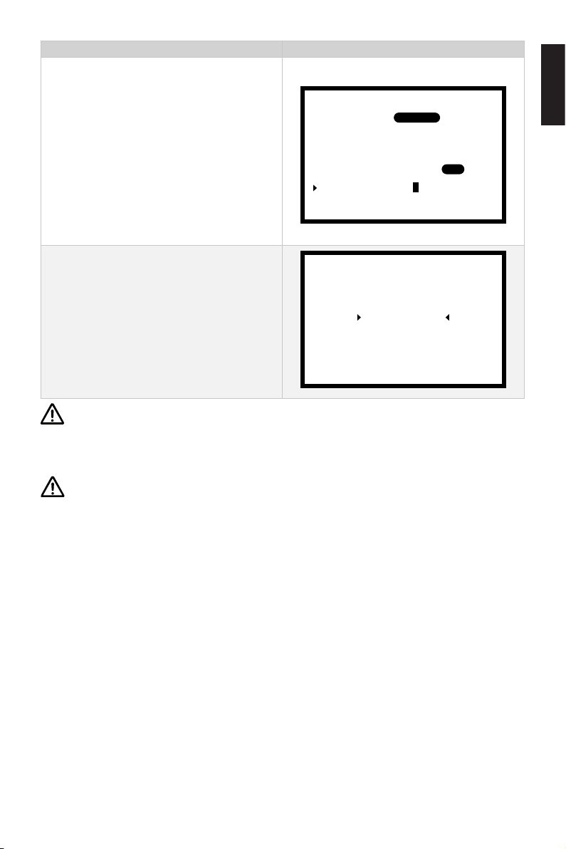
Battery Setting Process LCD Displaying
Step 10: Press the Conrm button to set
the battery undervoltage value. Please
set the three-digit value through the
selection buttons from left to right. After
each value is set, press the Conrm
button to move to the next value. The
ashing value is the value being edited.
Type:
Capacity:
Voltage Rating:
Hydrogeneration:
Undervolt Value:
0010 Ah
30.0 V
ON
30.0 V
Lead-acidLi-ion LiFePO4
OFF
The battery undervoltage setting range is
30-99.9V.
Power Limit
Step11: After battery setting is
completed, press the Menu button to
return to the preference setting page.
Unit Setting
Battery Setting
Throttle
Version
Lithium batteries, lead acid batteries and lithium iron phosphate batteries are
recommended to use with NAVY outboard or Pod Drive 3.0/6.0. Other types of
battery may fail to make the motor work properly.
English
Update the battery conguration is necessary if a different type of battery has
been applied.
27
Page 30
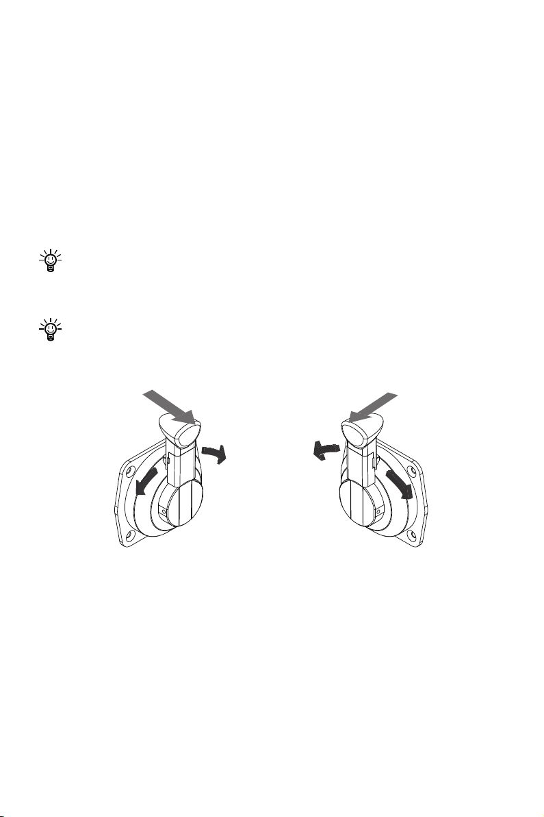
4.2 Throttle Operation
4.2.1 Power Adjusting
Evo Side Mount Control is used to adjust the input power of the motor. When the
battery is properly connected, power on the motor, and then start the Evo Side Mount
Control. When the throttle is in the neutral position, rst pull the handle away from its
base plate along a horizontal direction, then rotate the handle forward or backward to
increase the power. Please refer to gure 4-1 and 4-2. When the throttle returns to the
neutral position, it will lock automatically. Then need to pull out to continue turning
the throttle.
Before power on the Evo Side Mount Control, please reset the throttle to the neu-
tral position. If you nd a ickering “RESET” on the display, you are reminded to
reset the throttle to the neutral position.
The handle is locked only in the neutral position, there is no need to pull the handle towards outside once it's not in the neutral position.
Neutral Neutral
Backward
Figure 4-1 Port (left) side mode Figure 4-2 Starboard (right) side mode
Forward
Forward
Backward
28
Page 31
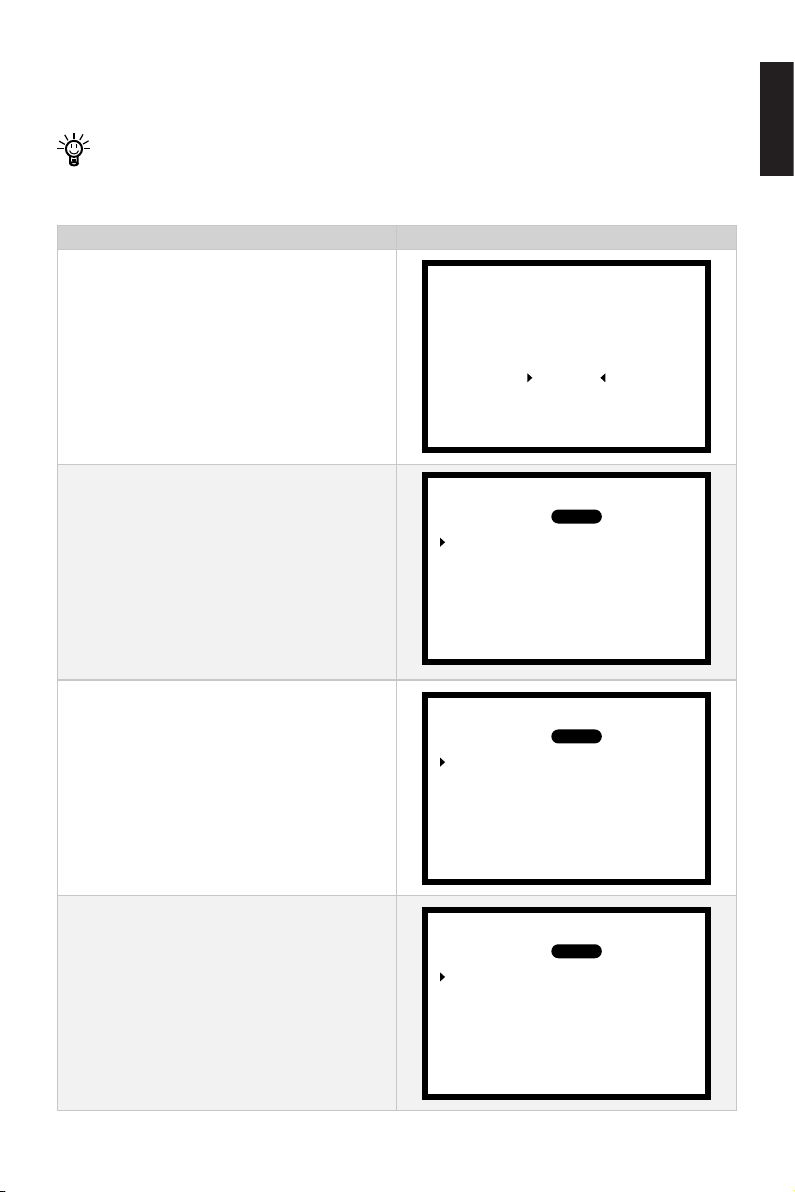
4.2.2 Recalibration
The throttle position sensor should be recalibrated if the below error code displays.
Before calibration, if there is no handle side setting, please refer to 2.5 Port and
Starboard Side Setting to set the handle side and then carry out the throttle calibration procedures.
Recalibration LCD Displaying
Step1: In power-on state, long press the
Menu button to enter the preference
setting page. Press the Select button
to switch to the "Throttle". Press the
Confirm button to enter throttle setting
Power Limit
Unit Setting
Battery Setting
Throttle
Version
page.
Step2: Press the Select button to switch
Handle Side:
Calibration
PORT
STBD
to the "Calibration". Press the Confirm
button to enter calibration setting page.
Push forward to the end
then press OK
English
Step3: Push the throttle to the maximum
forward power position, and then press
the Confirm button.
Step4: Pull the throttle to the neutral
position, then press the Confirm button.
29
Handle Side:
Calibration
Push to the neutral
Handle Side:
Calibration
Push backward to the end
PORT
then press OK
PORT
then press OK
STBD
STBD
Page 32
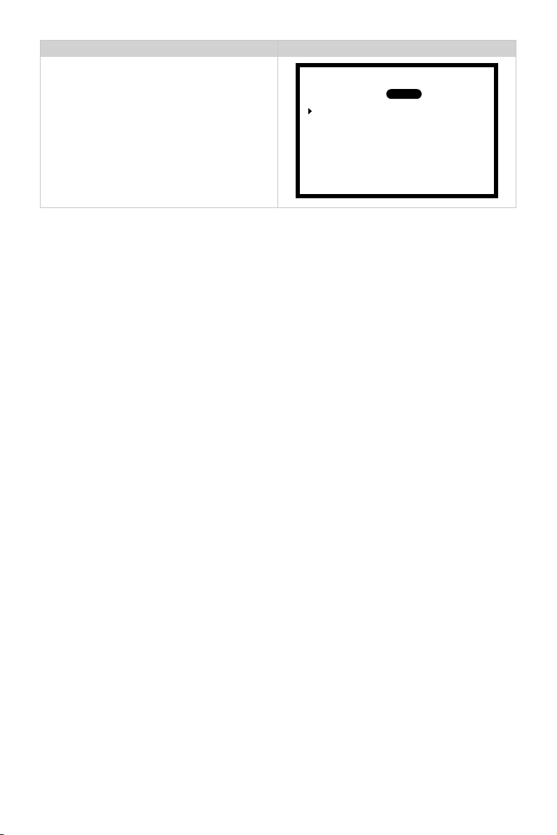
Recalibration LCD Displaying
Step5: Pull the throttle to the maximum
backward power position, and then
press the Confirm button. Calibration is
completed. Then press Confirm button
to return to throttle setting page.
Handle Side:
Calibration
Calibration complete.
PORT
Press OK
STBD
30
Page 33
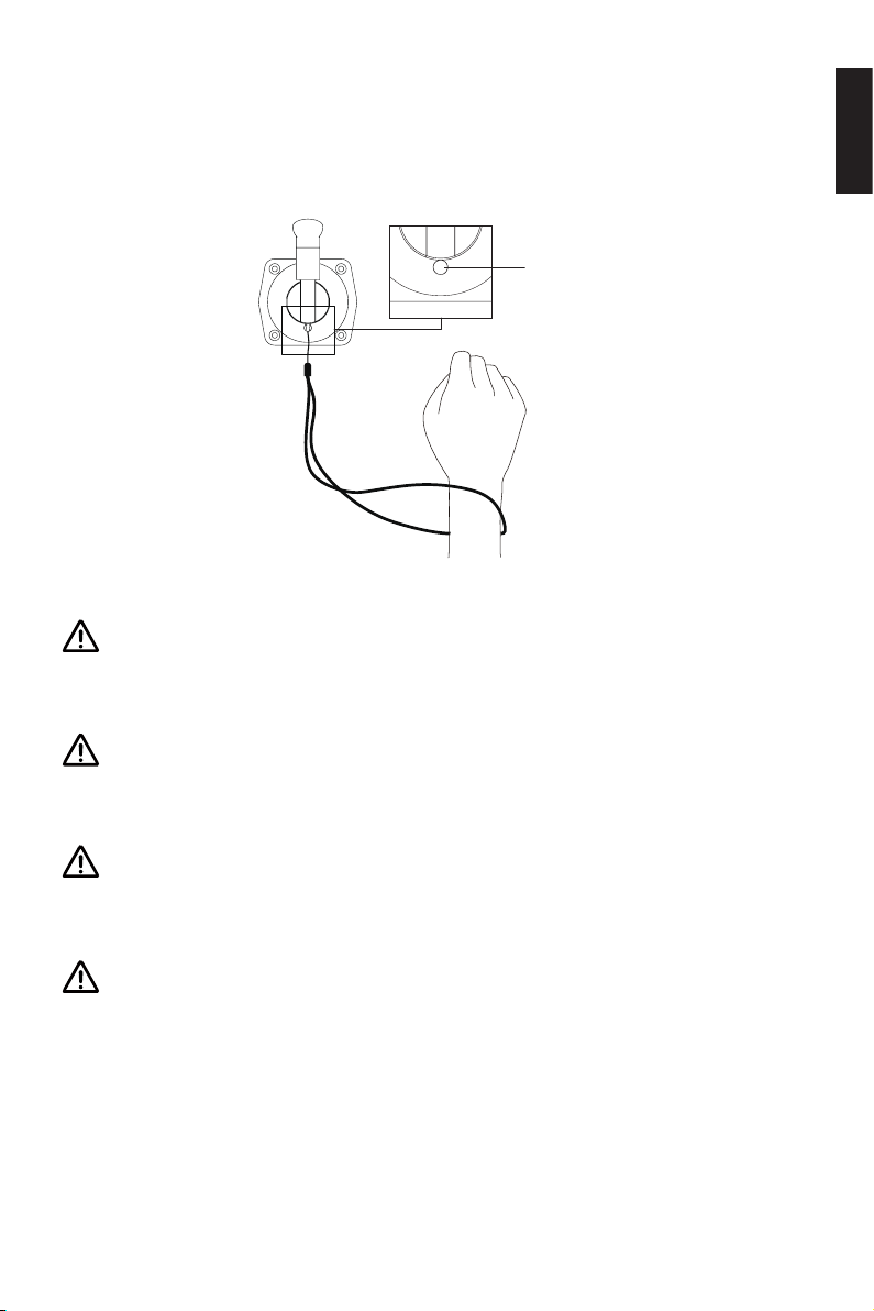
4.3 Use of Kill Switch
Locate the kill switch to the right place on the Evo Side Mount Control and tie its lanyard to your wrist or life jacket. Stop the outboard in emergency by detaching the kill
switch.
Kill Switch
Placement
Figure 4-7
Please remove the kill switch after the machine is turned off. Failure to remove
the kill switch will cause continuous power consumption of the battery (when
the battery is connected).
English
After connecting the machine and the battery, please attach the kill switch properly before turning on the machine, otherwise the machine will not work normally.
The kill switch generates magnetic field. Keep it 50cm / 20inches away from
medical implants like pacemakers and magnetic cards (e.g. credit card) as well
as other magnetic media.
The magnetic eld of the kill switch may interfere with some electronic instruments. Keep it away from these electronic instruments.
31
Page 34
4.4 Checklist before Use
1. Ensure the Evo Side Mount Control and steering wheel are installed in proper
position before turning on the power.
2. Ensure the Evo Side Mount Control travels smoothly with no obstructions.
3. Before connecting the battery, check and make sure there is no poor contacts or
defects in cables.
4. Before connecting to NAVY outboard or Pod Drive, please check and ensure the
main power switch is able to power on and off normally. After that, turn off the
main power switch.
5. Ensure the version setting of the Evo Side Mount Control is correspond to the
model of the motor.
6. Ensure the battery has enough power.
7. When not using ePropulsion Batteries, ensure the batteries is configured before
use.
Start the motor only when the propeller is beneath water, as the rotating propeller is dangerous.
If the cable is immersed in water, please dry it completely before connecting it to
the battery or power on the system.
32
Page 35

4.5 Starting the Motor
1. Complete the check list.
2. Remove the kill switch from the Evo Side Mount Control.
3. Set the throttle in the neutral position.
4. Connect the battery to the motor.
5. If using the outboard, fix the outboard with a proper trim angle.
6. Turn on the main power switch when using the NAVY outboard or Pod Drive. If the
outboard is connected to a E series battery, please also press the battery power
button to power on.
7. Press Power button to turn on the display panel, then the main page will display.
8. Carry out preference setting and battery configuration if necessary.
9. Tie the kill switch to your wrist or life vest, then attach the kill switch on the Evo
Side Mount Control.
10. Pull out the throttle in the neutral position, then push the throttle slowly to start
your motor.
If the display panel displays "Equipment oine":
1. Check the kill switch whether attached on the proper position.
2. Please using a communication cable to connect the motor or the battery
to the connector with the sign " " on the Evo Side Mount Control and use
another communication cable to connect the display panel to the other
connector with the sign " ".
3. If the connection is correct after double check, there may be the
communication fault between the display panel and the throttle. Please
check whether the communication cable is loosen or damaged.
English
33
Page 36
4.6 Stopping the Motor
Usually, it’s recommended to stop the motor as the following procedures.
1. Return the throttle to the neutral position, then the throttle will lock automatically.
2. Wait until the motor stops, then detach the kill switch from the Evo Side Mount
Control.
3. Press and hold the Power button until the Evo Side Mount Control is powered off.
4. If using the NAVY outboard or Pod Drive, turn off the main power switch. If the
outboard is connected to a E series battery, please also press the battery power
button to power off.
5. If using outboard, tilt the outboard above water surface or detach it from boat.
The motor will stop if one of the situations occurs.
1) The throttle is in the neutral position.
2) The kill switch is not in the kill switch placement of Evo Side Mount Control.
3) The main power switch is off, while using a NAVY outboard or Pod Drive.
4) The communication between Evo Side Mount Control and the motor breaks.
5) The connection between battery and the motor breaks.
6) Failure exists in the control system (e.g. motor is blocked or the low battery
voltage level is detected).
In case of emergency, the motor can be stopped by following operations:
1) Detach the kill switch.
2) Turn the throttle back to the neutral position.
34
Page 37
5 Warning Messages
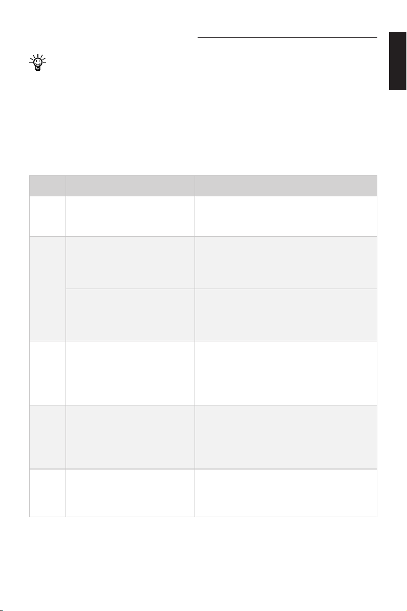
Before conducting warning checks, please check the version of the motor in use.
When the motor is running in abnormal conditions or out of order, a warning message
with an error code will display on the display panel. Please nd more error codes and
corresponding solutions in the below table.
a.Warning Massages (Evo Version)
The following error codes and solutions are applicable only to Evo outboard motor
and Pod Drive Evo.
Code Cause Solution
English
E01
E02
E06
E10
E11
Battery voltage beyond operation range.
Propeller may be blocked,
causing motor overcurrent
Motor fails or circuit board
fails causing motor overcurrent
The battery voltage level is
too low.
Motor stall, which may be
caused by blocked propeller
The temperature of motor is
too high.
Replace a battery based on suggested
operation specications.
Refer to Solution to E10.
Try to turn off the main switch and wait for
10 seconds then turn on the switch again.
Operate the motor at low power. Please
charge the battery as soon as possible.
Turn off power, then clean up the things
winding around the propeller. Test if the
propeller can be rotated by hand before
operation.
Stop operating the machine and wait until
the temperature falls within the normal
operating temperature range.
35
Page 38
Code Cause Solution
E12
E22
E30
E56
All characters
display
The temperature of circuit
board is too high.
MCU Communication Abnormality
Throttle position sensor
failure, should recalibrate
the throttle position sensor.
Communication Error between machine and battery
The motor has no power.
If the problem persists, please consult your ePropulsion authorized dealer for
assistance.
Stop operating the machine and wait until
the temperature falls within the normal
operating temperature range.
Please restart to see if the error disappears,
if not, please contact your dear for help.
Please refer to section 4.2.2 Recalibration to
recalibrate the throttle position sensor.
Check if the communication cable between
machine and battery is well connected, if
yes, please restart the system.
Connect the battery to the machine and
then turn on the main switch.
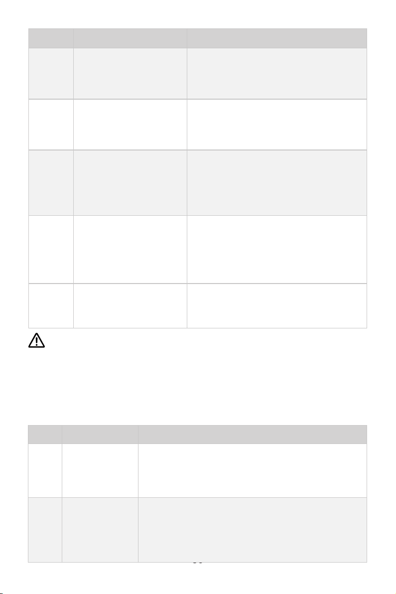
b.Warning Massages (Spirit1.0 & Pod1.0 Version)
The following error codes and solutions are applicable only to SPIRIT 1.0 outboard
motor and Pod Drive 1.0.
Code Cause Solution
Stop the motor and wait until the error message
disappears. If the problem still exists, contact your
dealer for repairing.
Disconnect the battery and check if the motor is
blocked. If not, continue driving at low speed. If this
issue cannot be solved, please contact your dealer.
E01
E02
Motor Over
Voltage
Motor Over
Current
36
Page 39
Code Cause Solution
E03/
E04
E05
E10 Motor Blocked
E20
E21
E30
Motor
Overheating
Motor Under
Voltage
Battery
Communication
Fault
Motor
Communication
Fault
Throttle
Calibration
Required
Wait a few minutes until the motor cools down and
the warning message disappears.
Indicate the battery level is extremely low. The motor
can probably be restarted at lower speed after the
message is dismissed.
Disconnect the battery and remove anything that is
blocking the motor. Make sure the propeller can be
rotated by hand smoothly.
Please check whether the version of Evo Side Mount
Control corresponds to the motor version first. If
not, please refer to
switching.
If the version is correct, turn off the motor and
reconnect the battery cable. If this issue cannot be
solved, please contact your dealer.
Turn off the motor and reconnect the battery cable.
If this issue cannot be solved please contact your
dealer.
Please refer to section 4.2.2 Recalibration to
recalibrate the throttle position sensor.
2.4 Version Setting
for version
English
Battery Charging
E51
E54
E55
Temperature
Discharging
Temperature
Battery Pack Over
Fault
Battery
Fault
Voltage
Make sure the environment temperature is within
0°C to 45°C. Charging will continue when cell
temperature is in that range.
Detach the battery and contact your dealer.
Stop the motor and wait until the error message
disappears. If the problem persists, contact your
dealer for repair.
37
Page 40
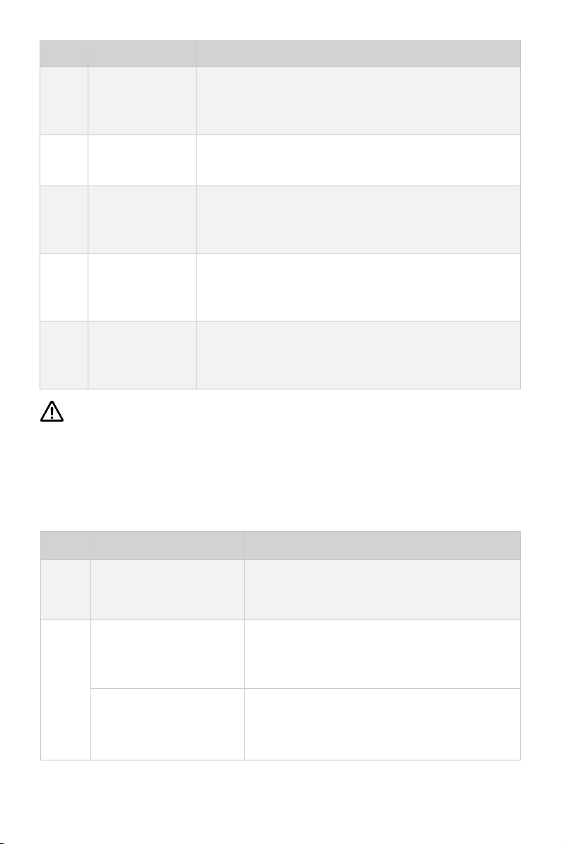
Code Cause Solution
Indicating the battery is empty. The motor can
E56 Battery Empty
Battery Charging
E57
E58
Over Current
Battery
Discharging Over
Current
probably be restarted at lower speed after the
message is dismissed.
Please contact your dealer.
Please contact your dealer.
Battery Hardware
E59
Other Battery Cell Fault
If the problem persists, please consult your ePropulsion authorized dealer for
assistance.
Fault
Battery has encountered serious hardware
breakdown. Please replace the battery and contact
your dealer.
Battery cell fault occurs, please replace the battery
and contact your dealer to repair the problematic
batter y.
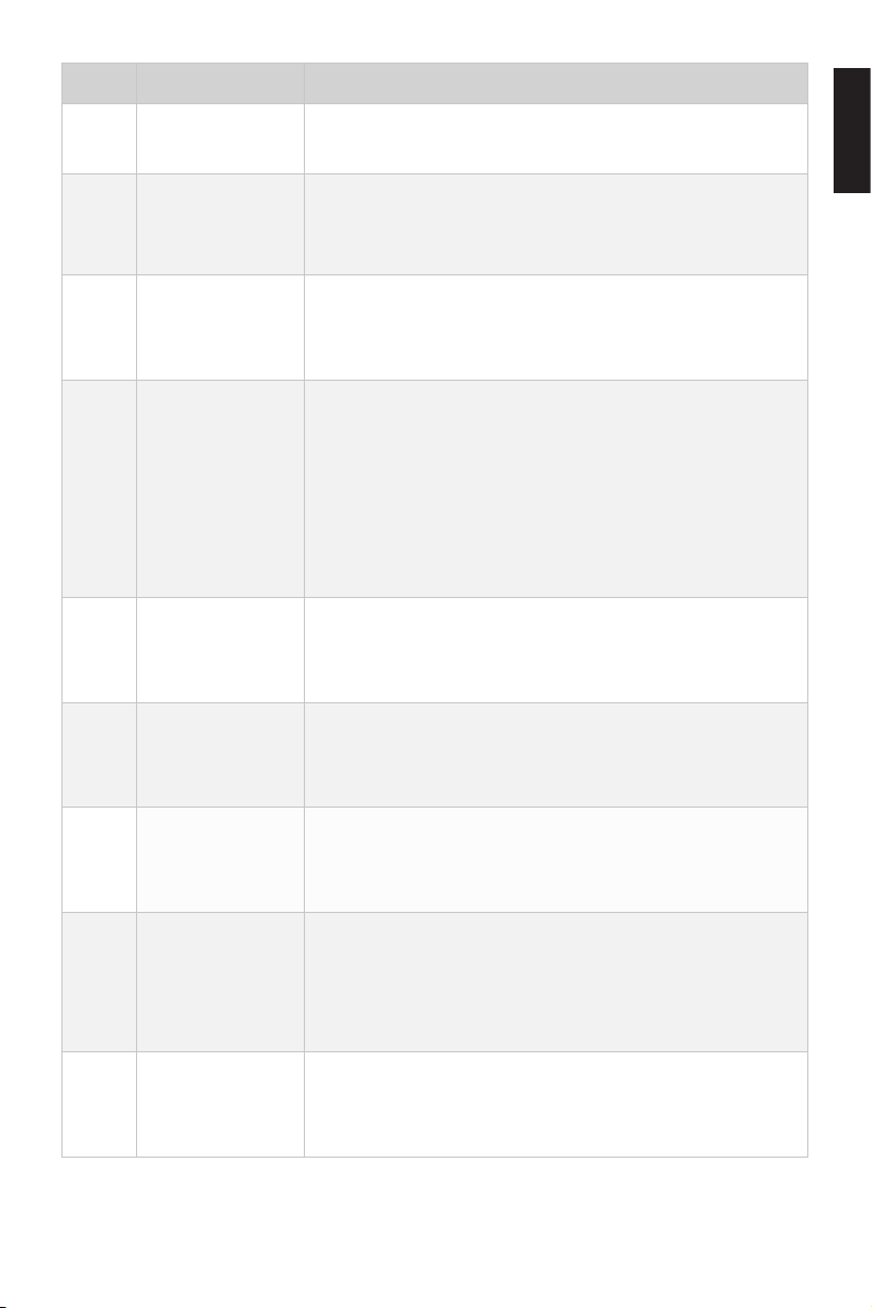
c.Warning Massages (Navy3.0, Navy6.0 & Pod3.0 Version)
The following error codes and solutions are applicable only to NAVY 3.0, NAVY 6.0
outboard motor and Pod Drive 3.0.
Code Cause Solution
E01
E02
Battery voltage is over
the operating range.
Propeller may be
blocked, causing motor
overcurrent
Motor fails or circuit
board fails causing motor
overcurrent
Replace a battery based on suggested
operation specifications.
Please refer to the solution to E10.
Try to turn off the main power switch and wait
for 10 seconds then turn on the switch again.
38
Page 41

Code Cause Solution
The battery voltage level
E06
is too low.
Motor stall, which may
E10
be caused by blocked
propeller
The temperature of
E11
motor is too high.
The temperature of
E12
circuit board is too high.
Failure was found in the
E15
circuit board temperature
sensors.
Calibration Abnormality
E16
of Current Sensor
Driver Communication
E21
Fault
Operate the motor at low power. Please charge
the battery as soon as possible.
Turn off power, then clean up the things winding
around the propeller. Test if the propeller can
be rotated by hand before operation.
Stop operating the motor and wait until the
temperature falls within the normal operating
temperature range.
Stop operating the motor and wait until the
temperature falls within the normal operating
temperature range.
Try to turn off the main power switch and wait
for 10 seconds then turn on the switch again.
Please contact the dealer for help.
Please check whether the version of Evo Side
Mount Control corresponds to the motor
version first. If not, please refer to
Setting
for version switching.
If the version is correct, check the
communication cable connection and restart
the motor. If the problem still arises, please
contact the ePropulsion authorized dealer for
assistance.
2.4 Version
English
E22
MCU Communication
Abnormality
Please restart to see if the error disappears, if
not, please contact your dear for help.
39
Page 42
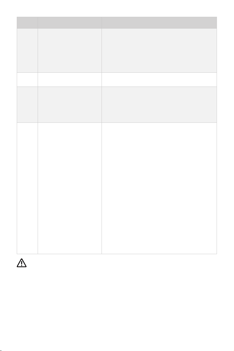
Code Cause Solution
Throttle position
E30
E40 System running failure Please restart the motor.
sensor failure, should
recalibrate the throttle
position sensor.
Please refer to section 4.2.2 Recalibration to
recalibrate the throttle position sensor.
E56
E57
Communication Error
between NAVY outboard
and E series battery
E series battery
overcurrent
Check if the communication cable between
NAVY outboard or Pod Drive 3.0 and E series
battery is well connected, if yes, please restart
the system.
1. Ensure the paralleled NAVY batteries have
similar voltage with pressure difference within
2V.
2. Ensure the power cable and battery are
firmly connected to avoid poor contact.
3. Restart the battery when the error occurs
and keep the parallel state for 30 minutes
to wait for the batteries to self-balance the
voltage.
4. If the error occurs, users can also continue
operating after restarting the battery, but do
not operate at full power state. The operating
power is suggested to be lower than two thirds
of full power. Please fully charge the battery
after use.
If the problem persists, please consult your ePropulsion authorized dealer for
assistance.
40
Page 43
6 Warranty
The ePropulsion limited warranty is provided for the rst end purchaser of an ePropulsion product. Consumers are entitled to a free repair or replacement of defective
parts or parts which do not conform with the sales contract. This warranty operates
in addition to your statutory rights under your local consumer law.
6.1 Warranty Policies
ePropulsion warrants its products to be free of defects in material and workmanship
for a limited period since the date of purchase. Once a fault is discovered, the user
has the right to make a warranty claim under the ePropulsion warranty policies.
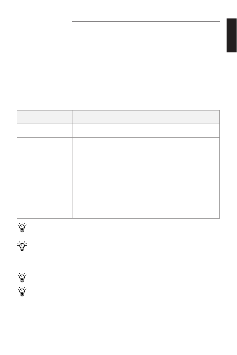
Product Warranty Expiry Date
English
Evo Side Mount
Control
Components
have been
repaired or replaced
In order to validate the warranty, users are required to ll in the Warranty Card in
the package in advance.
Keep the product label in intact state and record the serial number on the label.
Never tear the label off the product. An ePropulsion product without the original
product label will not be applicable to warranty services provided by ePropulsion.
The warranty is valid only when the information is correct and complete.
Free warranty is only validated upon the presentation of legal serial number,
Warranty Card, and evidence of purchase from an authorized ePropulsion dealer.
Valid date of purchase should be established by the rst-hand purchaser with
original sales slip.
Two years after the date of purchase.
Three months since the date of maintenance.
Note:
1. If the three-month period overlaps with the original
warranty period, the warranty against these
replaced or repaired parts still expires two years
after the date of purchase.
2. If the three-month period exceeds the original
warranty period, the repaired or replaced parts
continue applying to warranty during the extended
period.
41
Page 44

Free warranty is not transferable and will not be reissued.
Within the limits of the applicable laws, the warranty policies of ePropulsion may
update without prior notice. The latest version is available at our website www.
epropulsion.com.
6.2 Out of Warranty
Make sure the product is properly packed during delivery, the original ePropulsion
package is recommended. If the product got further damaged due to improper packing during delivery, the furtherly damaged part will be deemed as out of warranty coverage.
In addition, faults or damages caused by the following reasons are also excluded
from warranty scope within the covered period:
• Any improper operation contradicts the user manual.
• Accident, misuse, wishful abuse, physical damage, liquid damage, overcharging or
unauthorized repair.
• Dropping, improper care or storage.
• Used for commercial purposes.
You should be noted that minor faults like normal wear and tear that pose no
influence on the intended function of the product are also not covered by the
warranty.
Consumables are out of warranty scope.
6.3 Warranty Claim Procedures
If you nd your product defective, you can make a claim to your dealer following below procedures:
1. Fill in the Warranty Card correctly and completely in advance. Then make your
warranty claim by sending it to your authorized ePropulsion service partner
together with valid proof of purchase. Usually these documents are required
when making a warranty claim: the Warranty Card, ex-factory serial number, and
evidence of purchase.
2. Send the defective product to your authorized ePropulsion service point after
getting the confirmation. Note that the label should be kept intact. You can
also deliver the product to your authorized ePropulsion dealer after getting
confirmation.
42
Page 45

3. The defective components or parts will be either repaired or replaced according
to the diagnosis made by the ePropulsion authorized service partner.
4. If your warranty claim is accepted, the equipment will be repaired or replaced free
of charge. Note that any delivery cost incurred in the process is at your charge.
5. After careful examination and confirmation by ePropulsion authorized dealer, the
defective or faulty components will be repaired or replaced with brand new ones
against the actual condition.
6. In case your warranty claim be rejected, an estimated repair charge with round
trip delivery cost will be sent for confirmation. ePropulsion authorized service
point will conduct maintenance accordingly only after your confirmation.
If warranty expires, you can still enjoy maintenance services from authorized
ePropulsion service partners with minimum maintenance charge.
English
43
Page 46

Einleitung
Für Ihren Kauf von sowie Ihr Vertrauen in ePropulsion Produkte und unser Unternehmen bedanken wir uns herzlich. Wir haben uns zum Ziel gesetzt, umweltfreundliche,
sichere und zuverlässige elektrische Außenborder und Bootsantriebe herzustellen.
Für weitere Informationen besuchen Sie unsere Website: www.epropulsion.com.
Über diese Bedienungsanleitung
Vor dem Gebrauch lesen Sie bitte sorgfältig diese Bedienungsanleitung (nachfolgend
„Handbuch“ genannt), um ein komfortables und sicheres Erlebnis zu gewährleisten.
Die Verwendung dieses Produkts setzt voraus, dass der Kunde den Inhalt, insbesondere die Sicherheitshinweise, dieses Handbuches vollständig gelesen und verstanden hat. ePropulsion übernimmt keine Verantwortung für Personen-, Sach- und
Vermögensschäden, die durch Nichtbeachtung des Handbuchs entstehen.
Zur Verbesserung unserer Produkte behalten wir uns das Recht vor, Inhalte dieses
Handbuchs zu ändern. Ebenfalls gehören alle geistigen Eigentumsrechte, einschließlich (jedoch nicht beschränkt auf) aller Urheberrechte, Patente, Markenzeichen
und Designs ausschließlich der Fa. ePropulsion.
Dieses Handbuch unterliegt unregelmäßigen Änderungen. Für die aktuelle Version
besuchen Sie bitte unsere Website: www.epropulsion.com. Falls Sie Abweichungen
zwischen Ihrem Produkt und den Beschreibungen dieses Handbuchs feststellen oder
Fragen zum Produkt oder Handbuch haben, besuchen Sie bitte unsere Website www.
epropulsion.com oder nehmen Sie Kontakt mit uns auf. Das alleinige Recht für die
Erklärung zum Inhalt dieses Handbuchs ist ePropulsion vorbehalten. Dieses Handbuch ist in verschiedenen Sprachen vorhanden. Bei Abweichungen dient die englische
Version als Orientierung.
Symbole
Beim Lesen dieses Handbuchs beachten Sie bitte die folgenden Symbole:
Wichtige Hinweise und Warnungen
Nützliche Informationen zum Gebrauch
44
Page 47
Produktkennzeichnung
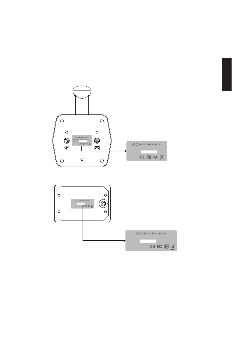
Die Seriennummer des Produkts dient als Nachweis bei der Inanspruchnahme der
Garantie- und Reparaturservices. Die Positionen der Seriennummern der Evo seitlichen Fernsteuerung sowie des Evo Bedienpanels entnehmen Sie den folgenden
Abbildungen. Bitte notieren Sie die beiden Nummern und bewahren Sie sie auf. Das
Typenschild darf auf keinen Fall entfernt werden, da die Garantie des Produkts sonst
erlischt.
Model: Side Mount Control
Serial No.:
Abb. 0-1
Deutsch
Model: Display Panel for Side Mount Control
Serial No.:
Abb. 0-2
45
Model: Display Panel for Side Mount Control
Serial No.:
Page 48

Inhaltsverzeichnis
Einleitung ....................................................................................................44
Über diese Bedienungsanleitung ..............................................................44
Symbole.......................................................................................................44
Produktkennzeichnung ..............................................................................45
1 Produktübersicht .....................................................................................48
1.1 Lieferumfang .....................................................................................48
1.2 Technische Daten ..............................................................................50
1.3 Wichtige Hinweise .............................................................................50
1.4 Konformitätserklärung .......................................................................51
2 Inbetriebnahme der Evo seitlichen Fernsteuerung ..............................52
2.1 Einbau des Gashebels ......................................................................52
2.1.1 Inneneinbau .............................................................................52
2.1.2 Außeneinbau ............................................................................53
2.2 Einbau des Evo Bedienpanels ..........................................................54
2.3 Anschluss ..........................................................................................56
2.4 Kompatible Außenborder auswählen ................................................57
2.5 Einstellung von Backbord und Steuerbord ........................................58
3 Beschreibungen der Module ..................................................................60
3.1 Demontierbarer Gashebel .................................................................60
3.1.1 Gri ausbauen ..........................................................................60
3.1.2 Gri einbauen ...........................................................................60
3.2 LCD-Display ......................................................................................61
4. Bedienung ...............................................................................................65
4.1 Konguration .....................................................................................65
4.1.1 Kompatible Außenborder auswählen .......................................65
4.1.2 Leistungsbegrenzung einstellen ...............................................66
4.1.3 Benutzerdenierte Einstellungen .............................................67
4.1.4 Batteriekonguration ................................................................68
4.2 Bedienung des Gashebels ................................................................73
4.2.1 Leistungseinstellung der Evo seitlichen Fernsteuerung ...........73
4.2.2 Kalibrieren ................................................................................73
46
Page 49

4.3 Verwendung des Reißleinenschalters ...............................................76
4.4 Kontrolle vor dem Betrieb ..................................................................77
4.5 Motor starten .....................................................................................78
4.6 Motor stoppen ...................................................................................79
5 Gewährleistung........................................................................................80
5.1 Garantiebedingungen ........................................................................80
5.2 Von der Garantie ausgenommen ......................................................81
5.3 Abwicklung eines Garantiefalls ..........................................................81
Deutsch
47
Page 50
1 Produktübersicht
Die kabelgebundene Evo seitliche Fernsteuerung besteht aus einem Bedienpanel sowie einem Gashebel und ist mit Außenbordern sowie Pod-Antrieben der Fa.
ePropulsion kompatibel.
1.1 Lieferumfang
Nach dem Öffnen der Verpackung überprüfen Sie bitte das Gerät auf mögliche Transportschäden. Bitte überprüfen Sie weiterhin die Vollständigkeit des Lieferumfangs
anhand der folgenden Liste. Bei Transportschäden oder fehlenden Teilen nehmen Sie
bitte Kontakt mit Ihrem zuständigen Vertragshändler auf.
Bezeichnung Anzahl Beschreibung
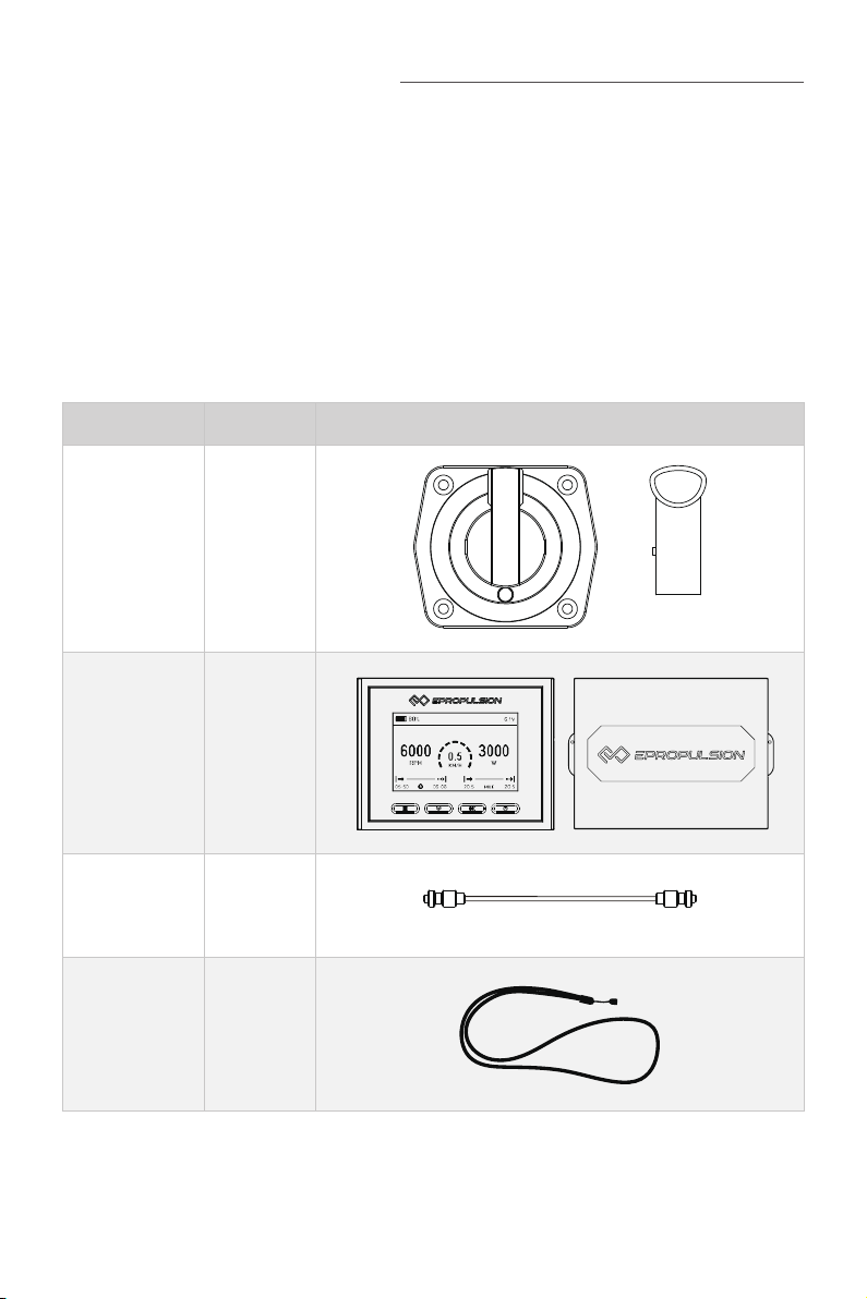
Gashebel 1 Stück
Evo Bedienpa-
nel
(mit Deckel)
Kommunikati-
onskabel 0,5m
Reißleinen-
schalter
1 Stück
1 Stück
2 Satz
0.5m
48
Page 51
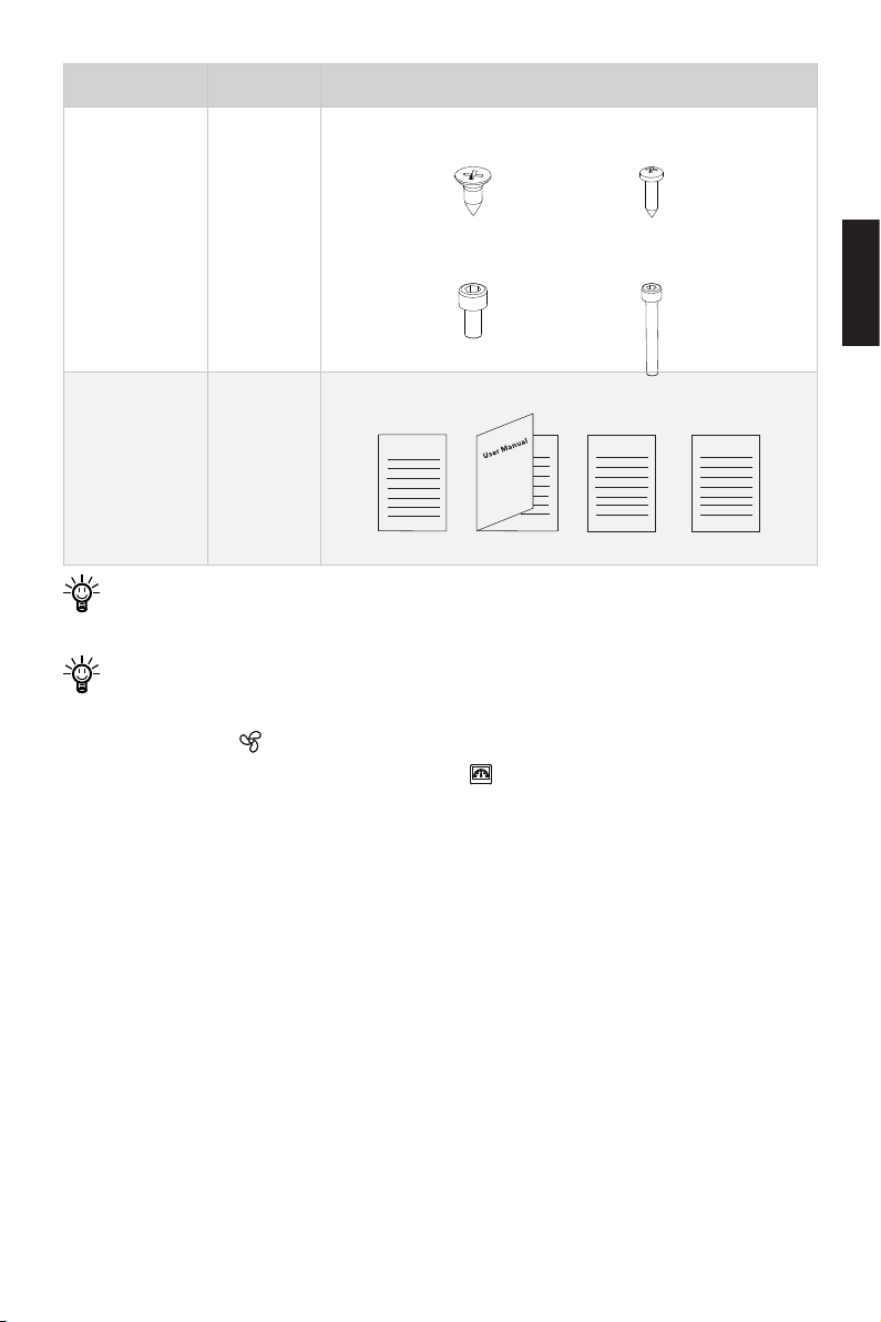
Bezeichnung Anzahl Beschreibung
×4
×4
M6X16
M6X12 M4X30
×4
Einbauteile 1 Satz
×8
M4X16
Bedienungs-
anleitung,
Garantiekarte,
Kurzanleitung,
Warranty
1 Satz
Fixing Guide Quick Start
Schablone für
Bohrungen
Für eine ordnungsgemäße Lagerung der Evo seitlichen Fernsteuerung bewahren
Sie bitte die Original-Verpackung auf.
Achten Sie auf die verschiedenen Anschlüsse, durch die die Evo seitliche Fernsteuerung mit dem Außenborder und dem Bedienpanel verbunden werden
kann. Der mit „ “ gekennzeichnete Anschluss muss mit dem Motor verbunden
werden. Der Anschluss mit dem Symbol „ “ wird mit dem Panel verbunden.
Deutsch
49
Page 52

1.2 Technische Daten
Evo Fernsteuerung für den seitlichen Einbau
Gewicht (mit Bedienpanel) 0,9 kg
Bedienpanel 4,3“ alleinstehend
Verbindungsart Kabel
Kabellänge ≤ 15 m
Abmessungen (L × T × H)
117 x 160,3 x 53,6 mm (Gashebel)
138,5 x 106,9 x 42,5 mm (Bedienpanel)
1.3 Wichtige Hinweise
1. Vor jeder Fahrt den Zustand der Evo seitlichen Fernsteuerung und den
Batteriestand kontrollieren.
2. Das Gerät darf nur von Erwachsenen bedient werden, die dieses Handbuch
vollständig gelesen und verstanden haben.
3. Vor jeder Inbetriebnahme die Funktionstüchtigkeit des Geräts überprüfen.
4. Vor der Inbetriebnahme sicherstellen, dass die Evo seitliche Fernsteuerung
ordnungsgemäß eingebaut ist.
5. Vor der Erstinbetriebnahme sich mit der grundlegenden Bedienung vertraut
machen, wie zum Beispiel Start, Stopp, Betriebsmodus und Not-Aus.
6. Wenn Personen während der Fahrt über Bord fallen, den Motor sofort stoppen.
7. Bei Kombination mit Navy-Außenbordern, Pod-Antrieben 3.0 Evo und 6.0 Evo
werden die angezeigten Distanzen und Geschwindigkeiten durch GPS bestimmt.
Bei schwachem oder durch äußerliche Faktoren (Strömungen, Wind usw.)
gestörtem GPS-Empfang können Abweichungen entstehen.
50
Page 53

1.4 Konformitätserklärung
Folgendes Produkt:
Produktbezeichnung: Evo seitliche Fernsteuerung
Typenbezeichnung: Evo Side Mount Control
Firmenbezeichnung: Guangdong ePropulsion Technology Limited
Firmenanschrift: Room 201, Bldg. 17A, 4th Xinzhu Road, Songshan Lake District,
Dongguan City, Guangdong Province, China
entspricht den Bestimmungen der folgenden Richtlinien:
EMV-Richtlinie 2014/30/EU (Richtlinie über die elektromagnetische Verträglichkeit)
FCC (Federal Communications Commission Regulations) Part 15, Voraussetzungen: Dieses Gerät verursacht keine gefährlichen Störsignale und kann Störsignale empfangen, ohne dass Funktionsbeeinträchtigungen auftreten.
Folgende Normen wurden angewandt:
EN 55014-1:2017
EN 55014-2:2015
EN 61000-3-2:2014
EN 61000-3-3:2013
FCC (Federal Communications Commission Regulations) Part 15, Voraussetzungen: Dieses Gerät verursacht keine gefährlichen Störsignale und kann Störsignale empfangen, ohne dass Funktionsbeeinträchtigungen auftreten.
Deutsch
Unterschrift:
Shizheng Tao (CEO und Mitgründer der Guangdong ePropulsion Technology Limited)
51
Page 54
2 Inbetriebnahme der Evo seitlichen Fernsteuerung
Zur Inbetriebnahme der Evo seitlichen Fernsteuerung müssen der Gashebel und das
Evo Bedienpanel eingebaut und anschließend über Kabel mit dem Motor und der Batterie verbunden werden. Backbord und Steuerbord müssen eingestellt werden und bei
Nicht-Evo-Motoren sind Anpassungen vorzunehmen.
Vor der Inbetriebnahme muss das Gerät vollständig anschlossen werden.
Darüber hinaus muss es auf die einwandfreie Funktionalität sowie richtige Verkabelung überprüft werden. Anschluss der Kabel entsprechend der Beschreibungen im Kapitel 2.3 durchführen.
2.1 Einbau des Gashebels
Anhand der folgenden Beschreibungen den Gashebel der Evo seitlichen Fernsteuerung in den Bootsrumpf einbauen. Der Gashebel kann wahlweise von innen oder
außen eingebaut werden.
2.1.1 Inneneinbau
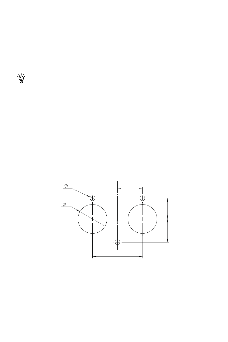
1. Anhand des folgenden Lochbildes Löcher in den Rumpf bohren.
6
30
35
28 25
60
Abb. 2-1
52
Page 55
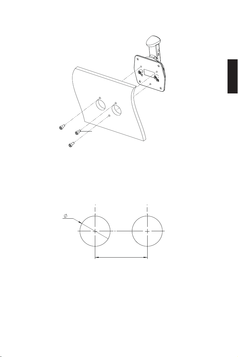
2. Den Gashebel wie in der Abbildung rechts dargestellt in den Rumpf einbauen und
befestigen.
M6-Schrauben
Abb. 2-2
2.1.2 Außeneinbau
1. Anhand des folgenden Lochbildes Löcher in den Rumpf bohren.
Deutsch
35
60
Abb. 2-3
2. Den Gashebel wie in der Abbildung unten dargestellt in den Rumpf einschieben und
befestigen.
53
Page 56
M6-Schrauben
102
38
Abb. 2-4
2.2 Einbau des Evo Bedienpanels
Anhand der folgenden Beschreibungen das Bedienpanel der Evo seitlichen Fernsteuerung in den Bootsrumpf einbauen.
1. Anhand des folgenden Lochbildes Löcher in den Rumpf bohren.
4 X
3
19
20
4
Abb. 2-5
54
Page 57
2. Die Verkleidung des Panels entfernen.
3. Das Evo Bedienpanel wie in der Abbildung unten dargestellt in den Rumpf einbauen
und befestigen.
Verkleidung
M3-Bohrschrauben
Abb. 2-6
Deutsch
55
Page 58
2.3 Anschluss
Mit Bedienpanel verbinden
Die Verbindung zwischen der Evo seitlichen Fernsteuerung und dem Motor wird durch
Kabel hergestellt. Nachfolgend werden die Arbeitsschritte des Anschlusses beschrieben:
1. Evo seitliche Fernsteuerung mit dem Verbindungskabel an den Motor anschließen.
2. Den Motor mit der Batterie verbinden.
Abb. 2-7
Der mit „ “ gekennzeichnete Anschluss muss an den Motor angeschlossen
werden. Der Anschluss mit dem Symbol „ “ wird mit dem Panel verbunden.
Mit Motor verbinden
Abb. 2-8
Falls „Equipment oine“ angezeigt wird, überprüfen Sie, ob der Reißleinenschalter richtig eingebaut wurde. Wenn der Reißleinenschalter richtig eingebaut ist,
dann gehen Sie wie auf Seite 31 beschrieben mit der Prüfung vor.
56
Page 59
2.4 Kompatible Außenborder auswählen
Wenn die Evo seitliche Fernsteuerung mit einem Evo Motor verbunden ist, wird die
Evo Version automatisch erkannt. Bei anderen Motormodellen von ePropulsion ist
die Version „Spirit 1.0“ voreingestellt. Falls eine Kombination mit der Navy-Serie bzw.
Pod-Antrieben gewünscht ist, gehen Sie für eine Umstellung auf die entsprechenden
Versionen wie folgt vor:
Arbeitsschritte Anzeige auf dem Display
Schritt 1: Im eingeschalteten Zustand
durch langes Drücken der Menü-Taste
in das Setup-Menü gelangen. Mit der
Auswahltaste den Menüpunkt „Version“
wählen. Mit der OK-Taste bestätigen,
um zu den Einstellungen der Version zu
gelangen.
Schritt 2: Mit der Auswahltaste die gewünschte Version des Motors auswählen.
Power Limit
Unit Setting
Battery Setting
Throttle
Version
Navy 3.0
Navy 6.0
Pod 1.0
Pod 3.0
EVO
Deutsch
Schritt 3: Durch Drücken der OK-Taste
wird die aktuelle Einstellung gespeichert.
Das Display wechselt automatisch in das
Setup-Menü zurück.
Power Limit
Unit Setting
Battery Setting
Throttle
Version
57
Page 60
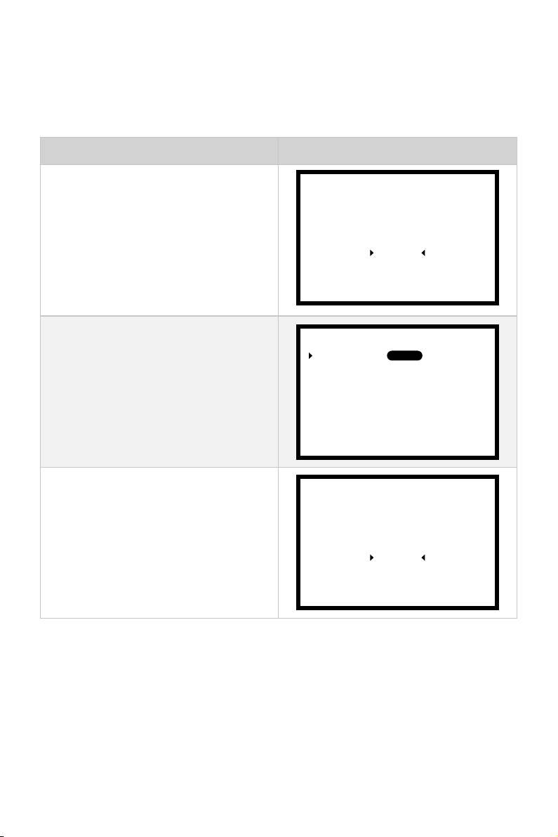
2.5 Einstellung von Backbord und Steuerbord
Vor dem Betrieb müssen Backbord oder Steuerbord eingestellt werden. Bei der Lieferung der Evo seitlichen Fernsteuerung ist Steuerbord voreingestellt. Bei Bedarf kön-
nen Sie wie unten beschrieben zwischen Backbord und Steuerbord umschalten.
Arbeitsschritte Anzeige auf dem Display
Schritt 1: Im eingeschalteten Zustand
durch langes Drücken der Menü-Taste
in das Setup-Menü gelangen. Mit der
Auswahltaste den Menüpunkt „Throttle“
wählen. Mit der OK-Taste bestätigen, um
zu den Einstellungen des Gashebels zu
gelangen.
Schritt 2: Mit der OK-Taste die Option
„Handle Side“ aktivieren, um Backbord
und Steuerbord einzustellen. Mit der Auswahltaste „PORT“ (für Backbord) oder
„STBD“ (für Steuerbord) wählen und mit
der OK-Taste die Einstellung speichern.
Handle Side:
Calibration
Power Limit
Unit Setting
Battery Setting
Throttle
Version
STBDPORT
Schritt 3: Durch kurzes Drücken auf die
Menü-Taste in das übergeordnete Menü
zurückzukehren.
Power Limit
Unit Setting
Battery Setting
Throttle
Version
58
Page 61
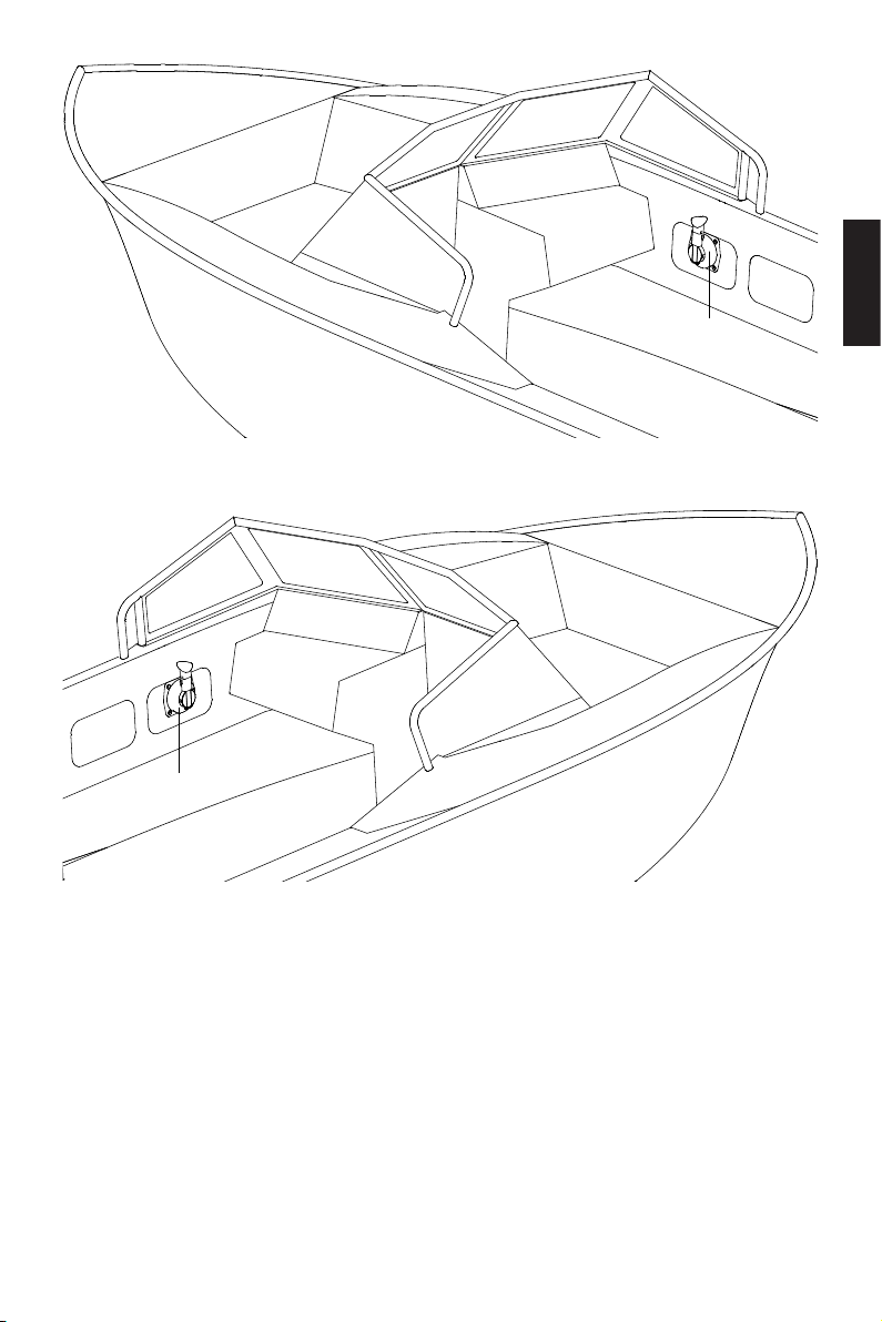
Throttle
Throttle
Abb. 2-9 Steuerbord
Abb. 2-10 Backbord
Deutsch
59
Page 62
3 Beschreibungen der Module
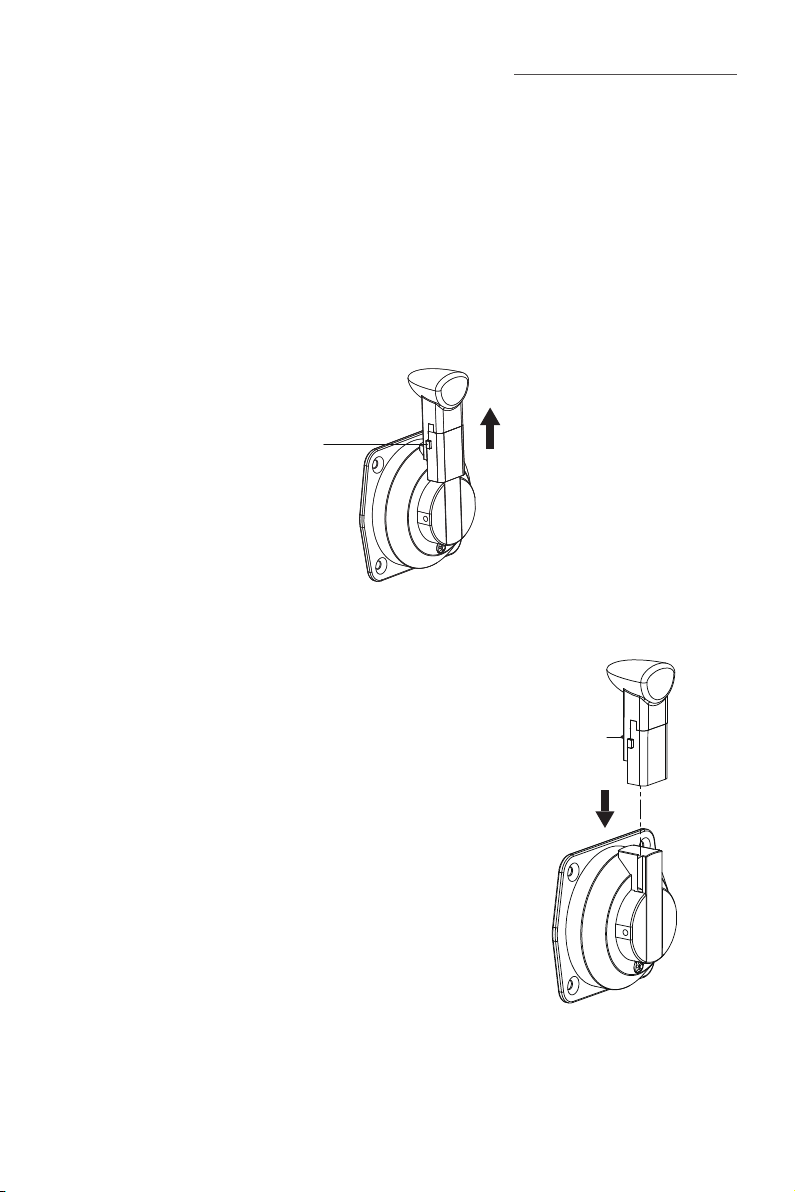
Entriege
lungsknopf
Über Anschlusskabel mit dem Motor verbunden dient die Evo seitliche Fernsteuerung
zum Start/Stop des Motors, zur Einstellung der Fahrgeschwindigkeit und der Batterieparameter sowie zum Anzeigen der Systemmeldungen.
3.1 Demontierbarer Gashebel
3.1.1 Griff ausbauen
Im Werkszustand ist der Griff des Gashebels bereits eingebaut. Bei Bedarf können Sie
den Griff nach oben herausziehen, während Sie den Entriegelungsknopf drücken.
-
Abb. 3-1
3.1.2 Griff einbauen
Zum Einbau des Griffes führen Sie ihn über den
Führungsschlitz nach unten, bis der Entriegelungsknopf
einrastet.
Abb. 3-2
60
Griffes
Page 63
3.2 LCD-Display
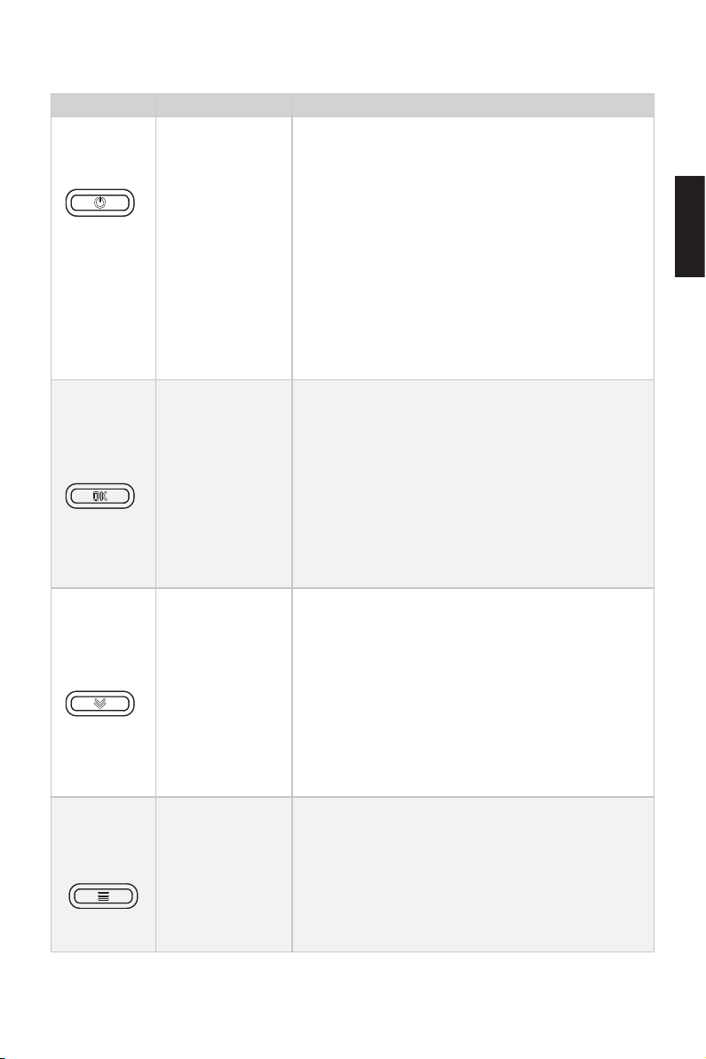
Tasten Funktionen
EIN/AUS-Taste
OK-Taste
Auswahltaste
Menü-Taste
1. Im ausgeschaltetem Zustand kann das
LCD-Display durch langes Drücken der EIN/
AUS-Taste eingeschaltet werden.
2. Im eingeschaltetem Zustand kann das LCD-Display durch langes Drücken der EIN/AUS-Taste
ausgeschaltet werden.
3. Im eingeschaltetem Zustand kann die Hintergrundbeleuchtung des LCD-Displays durch kurzes
Drücken der EIN/AUS-Taste ein- bzw. ausgeschaltet werden.
1.Im Hauptmenü kann durch Drücken der OK-Taste zwischen der Anzeige des Batteriestands und
der Spannung gewechselt werden.
2. Im Setup-Menü werden vorgenommene Einstellungen durch Drücken der OK-Taste gespeichert.
Beim Einstellen eines Parameters können Sie
durch Drücken der Taste zu der nächsten Ziffer
gelangen.
1. Bei Navy-Modellen und Pod-Antrieben 3.0/6.0
kann durch Drücken der Auswahltaste im Hauptmenü zwischen der Anzeige der Fahrgeschwindigkeit und der Distanz gewechselt werden.
2. Im Setup-Menü kann durch Drücken der Auswahltaste zwischen den Einstelloptionen gewechselt werden bzw. die Einstellungen können angepasst werden.
1. Im eingeschalteten Zustand gelangt man durch
langes Drücken der Menü-Taste im Hauptmenü in
das Setup-Menü.
2. Im Setup-Menü wechselt man durch kurzes
Drücken der Menü-Taste in das Hauptmenü bzw.
das höhere Menü zurück.
Deutsch
61
Page 64
Bitte schalten Sie das Display erst ein, nachdem Sie den Reißleinenschalter an
100%
48.0V
die seitliche Fernsteuerung angeschlossen haben. Sonst erscheint „Oine“ auf
dem Display und das Gerät funktioniert nicht.
Die Stromversorgung muss hergestellt werden, bevor die Bedienung des
LCD-Displays möglich ist.
Werden keine Änderungen zu den Parametern in diesem Menü vorgenommen,
so werden die angezeigten Werte als Voreinstellungen für den Benutzer gespeichert.
Beschreibung Funktionen
Batteriestandsanzeige
Batteriespannung/
Kapazität
Rekuperationsanzeige
GPS-Anzeige
Zeigt den aktuellen Batteriestand an.
48,0 V: zeigt die aktuelle Batteriespannung an.
100 %: zeigt den prozentualen Ladezustand
der Batterie an.
Bei Modellen, die Rekuperation unterstützen,
kann diese Funktion im Setup-Menü aktiviert
bzw. deaktiviert werden.
Leuchtet dauerhaft: Rekuperation ist aktiviert.
Blinkt: Rekuperation läuft.
Leuchtet nicht: Rekuperation ndet nicht statt
oder ist deaktiviert.
Leuchtet nicht: kein Empfang oder GPS funktioniert nicht.
Blinkt: GPS empfängt Signal.
Leuchtet dauerhaft: GPS-Empfang ist gut und
aktiviert.
Bei den Antrieben Spirit 1.0 oder Pod 1.0
wird die GPS-Anzeige dauerhaft ausgeblendet.
62
Page 65
Beschreibung Funktionen
6000
RPM
3000
W
Leuchtet nicht: Temperatur im Normalbereich.
Blinkt: Temperatur leicht erhöht. Der Übertem-
peraturschutz wird aktiviert und die Leistung
Warnung Übertemperatur Motor
gesenkt.
Leuchtet dauerhaft: Temperatur zu hoch. Ge-
rät schaltet sich aus. Erst nach dem Erreichen
einer niedrigeren Temperatur kann das Gerät
wieder eingeschaltet werden.
Leuchtet nicht: Temperatur im Normalbereich.
Blinkt: Temperatur leicht erhöht. Der Übertem-
peraturschutz wird aktiviert und die Leistung
Warnung Übertemperatur Steuerung
gesenkt.
Leuchtet dauerhaft: Temperatur zu hoch. Ge-
rät schaltet sich aus. Erst nach dem Erreichen
einer niedrigeren Temperatur kann das Gerät
wieder eingeschaltet werden.
Störung Ventilator
Leuchtet nicht: Ventilator im Normalbetrieb
Blinkt: Ventilator gestört
Leuchtet nicht: Gashebel muss nicht in die
Rest-Anzeige Gashebel
Grundposition geschaltet werden
Blinkt: Gashebel muss in die Grundposition
geschaltet werden
Deutsch
0.5
KM/H
Aktuelle Leistung Zeigt die Echtzeit-Leistung des Geräts an.
Zeigt die Echtzeit-Fahrgeschwindigkeit des
Bootes an. Im Menü „Unit Setting“ kann die
Aktuelle Geschwindigkeit
gewünschte Einheit (MPH, KM/H oder KNOTS)
eingestellt werden.
Bei den Antrieben Spirit 1.0 oder Pod
1.0 wird das Firmenlogo anstatt der Geschwindigkeit dargestellt.
Aktuelle Drehzahl Zeigt die aktuelle Drehzahl des Motors an
63
Page 66
Beschreibung Funktionen
Anzeige : Vorwärts
Position Gashebel
Status Reißleinenschalter
Zurückgelegte Strecke oder abgelaufene Zeit / verbleibende Strecke oder Zeit
Anzeige Zeit
Anzeige Strecke
Anzeige : NULL
Anzeige : Rückwärts
Leuchtet nicht: Reißleinenschalter ist ange-
schlossen.
Blinkt: Reißleinenschalter ist nicht angeschlos-
sen.
: zurückgelegte Strecke oder abgelaufene
Zeit.
: verbleibende Strecke oder Zeit.
Zeigt die abgelaufene Zeit / verbleibende Zeit
an.
Zeigt die zurückgelegte Strecke / verbleibende
Strecke an. Im Menü „Unit Setting“ kann die
gewünschte Einheit, MILE, KM (Kilometer)
oder NM (Seemeile), eingestellt werden.
64
Page 67
4. Bedienung
4.1 Konguration
4.1.1 Kompatible Außenborder auswählen
Wenn die Evo seitliche Fernsteuerung mit einem Evo Motor verbunden ist, wird die
Evo Version automatisch erkannt. Bei anderen Motormodellen von ePropulsion wird
die Version „Spirit 1.0“ eingestellt. Falls eine Kombination mit der Navy-Serie bzw.
Pod-Antrieben gewünscht ist, gehen Sie für eine Umstellung auf die entsprechenden
Versionen wie folgt vor:
Arbeitsschritte Anzeige auf dem Display
Schritt 1: Im eingeschalteten Zustand
durch langes Drücken der Menü-Taste
in das Setup-Menü gelangen. Mit der
Auswahltaste den Menüpunkt „Version“
wählen. Mit der OK-Taste bestätigen,
um zu den Einstellungen der Version zu
gelangen.
Schritt 2: Mit der Auswahltaste die gewünschte Version des Motors auswählen.
Power Limit
Unit Setting
Battery Setting
Throttle
Version
Navy 3.0
Navy 6.0
Pod 1.0
Pod 3.0
EVO
Deutsch
Schritt 3: Durch Drücken der OK-Taste
wird die aktuelle Einstellung gespeichert.
Das Display wechselt automatisch in das
Setup-Menü zurück.
Power Limit
Unit Setting
Battery Setting
Throttle
Version
65
Page 68
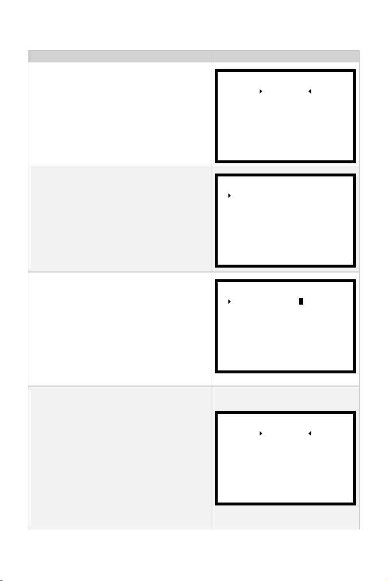
4.1.2 Leistungsbegrenzung einstellen
Arbeitsschritte Anzeige auf dem Display
Schritt 1: Im eingeschalteten Zustand durch
langes Drücken der Menü-Taste in das Setup-Menü gelangen. Mit der Auswahltaste
den Menüpunkt „Power Limit“ wählen. Mit der
OK-Taste bestätigen, um zu den Einstellungen
der Leistungsbegrenzung zu gelangen.
Schritt 2: Mit der Auswahltaste die einzustellende Leistung auswählen. „Forward Limit“
steht für die Leistung bei der Vorwärtsfahrt
und „Backward Limit“ für die Leistung bei der
Rückwärtsfahrt. Mit der OK-Taste die Auswahl bestätigen.
Schritt 3: Mit der Auswahltaste stellen Sie den
dreistelligen Wert Ziffer für Ziffer von links
nach rechts ein. Nach der Einstellung drücken
Sie die OK-Taste, um zur nächsten Ziffer zu
wechseln. Die momentan einzustellende Ziffer blinkt. Der Einstellbereich ist 1 % – 100 %.
Beim Navy 6.0 beträgt der Einstellbereich für
die Rückwärtsbegrenzung 1 % – 50 %.
Schritt 4: Nachdem alle Ziffern für die Vorwärtsbegrenzung eingestellt sind, kann durch
kurzes Drücken der Menü-Taste in das vorherige Menü oder durch kurzes Drücken der
Auswahltaste zu der Rückwärtsbegrenzung
gewechselt werden. Nachdem die beiden
Begrenzungen eingestellt sind, wechselt man
durch kurzes Drücken der Menü-Taste zum
Setup-Menü. Die Einstellungen werden gespeichert.
Power Limit
Unit Setting
Battery Setting
Throttle
Version
Forward Limit:
Backward Limit:
Forward Limit:
Backward Limit: 001 %
Battery Setting
001 %
001 %
001 %
Power Limit
Unit Setting
Throttle
Version
66
Page 69
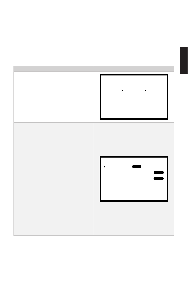
4.1.3 Benutzerdefinierte Einstellungen
Bei Kombination mit der Navy-Serie oder den Pod-Antrieben 3.0 und 6.0 müssen die
Einheiten für Geschwindigkeit und Strecke aktiviert werden. Vor der Einstellung muss
die Version Ihrer Evo seitlichen Fernsteuerung auf Evo, Navy 3.0, Navy 6.0 oder Pod
3.0 eingestellt sein. Bevor Sie Ihre Evo seitliche Fernsteuerung in Betrieb nehmen,
sollten Sie die benutzerdenierten Einstellungen wie nachfolgend beschrieben durchführen.
Arbeitsschritte Anzeige auf dem Display
Schritt 1: Im eingeschalteten Zustand
durch langes Drücken der Menü-Taste in
das Setup-Menü gelangen. Mit der Auswahltaste den Menüpunkt „Unit Setting“
wählen. Mit der OK-Taste bestätigen, um
zu den benutzerdenierten Einstellungen
zu gelangen.
Schritt 2: Mit der Auswahltaste die einzustellende Einheit auswählen.
Bei der Einstellung „Battery“ handelt es
sich um die Anzeige des Batteriestands
oder der Batteriespannung.
Bei „Speed Unit“ geht es um die Einheit
der Geschwindigkeit und bei „Distance
Unit“ um die Einheit der Strecke.
Durch kurzes Drücken der OK-Taste
die jeweilige Einstellung anwählen. Mit
der Auswahltaste die gewünschte Einheit auswählen und anschließend mit
der OK-Taste bestätigen. Ausgewählte
Einheiten werden mit schwarzem Hintergrund dargestellt. Durch kurzes Drücken
der Menü-Taste zurückkehren.
Battery:
Speed Unit:
Distance Unit:
Power Limit
Unit Setting
Battery Setting
Throttle
Version
SOC
KNOTS
NM
Volt
MPH
MILE
KM/H
KM
Deutsch
67
Page 70
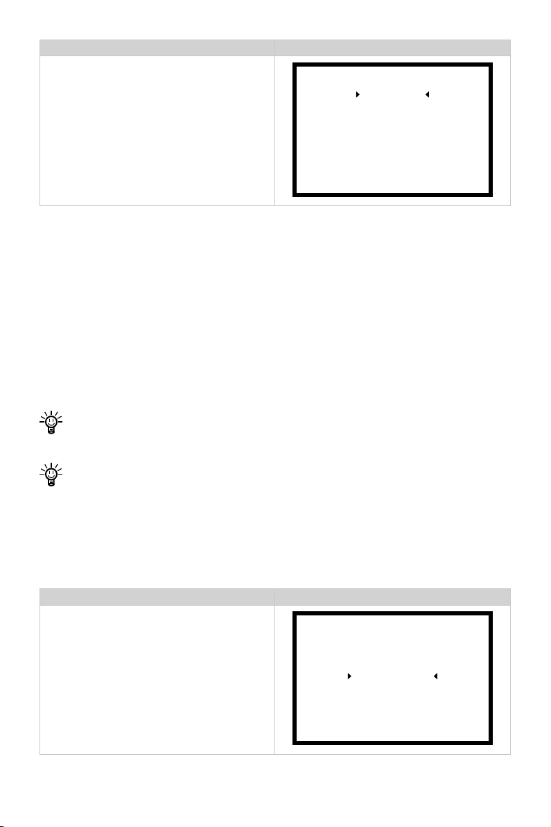
Arbeitsschritte Anzeige auf dem Display
Power Limit
Schritt 3: Menü-Taste kurz drücken, um
in das Setup-Menü zurückzukehren.
Unit Setting
Battery Setting
Throttle
Version
4.1.4 Batteriekonfiguration
Eine genaue Batteriekonfiguration trägt zur genauen Anzeige des Entladezustands
der Batterie bei. Bei der Verwendung von ePropulsion Batterien werden die Kongurationen automatisch von der Steuerung durchgeführt, nachdem die Batterien mit Kabel
an die Steuerung angeschlossen wurden. Die Rekuperation kann entweder aktiviert
oder deaktiviert werden. Bei der Verwendung von Fremdbatterien muss der Benutzer
vor der Erstinbetriebnahme über das Display der Evo seitlichen Fernsteuerung die Bat-
teriekonguration manuell durchführen, um die genaue Anzeige des Batteriestands
zu gewährleisten.
Bei der Verwendung von ePropulsion Spirit Batterien ist keine Konguration notwendig.
Beim erstmaligen Wechsel auf eine Batterie mit abweichenden Kapazitäten /
Spannungen muss diese neu konguriert werden, bevor sie an den Außenborder
angeschlossen werden kann. Da bei der Berechnung der Batteriestandsanzeige
gewisse Ungenauigkeiten nicht zu vermeiden sind, sollte der Benutzer die Fahrt
sicher planen, indem er mehr als 15 % des benötigten Batteriestands als Reserve
berücksichtigt oder eine Backup-Batterie mit genug Ladung mit an Bord nimmt.
Arbeitsschritte Anzeige auf dem Display
Schritt 1: Im eingeschalteten Zustand
durch langes Drücken der Menü-Taste
in das Setup-Menü gelangen. Mit der
Auswahltaste den Menüpunkt „Battery
Setting“ wählen. Mit der OK-Taste bestä-
Power Limit
Unit Setting
Battery Setting
Throttle
Version
tigen, um zu den Batterieeinstellungen zu
gelangen.
68
Page 71
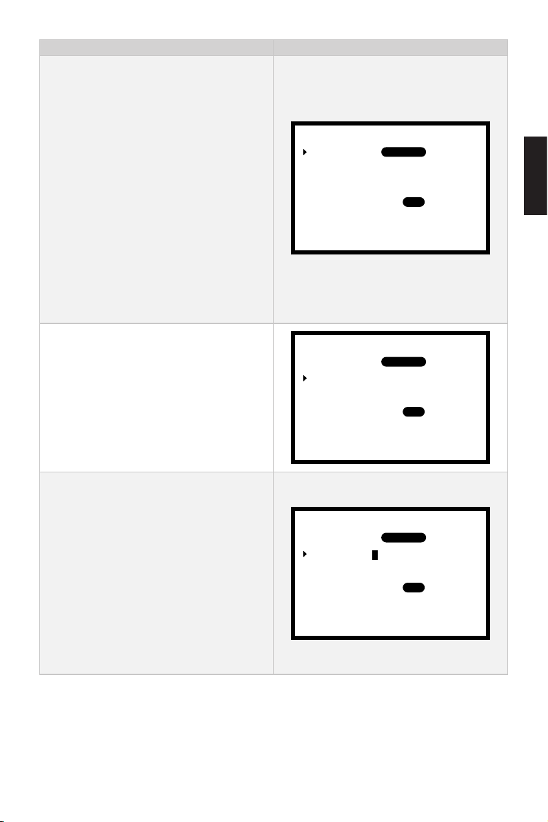
Arbeitsschritte Anzeige auf dem Display
Schritt 2: Wenn der Pfeil vor der Option
„Type“ steht, die OK-Taste drücken und
den Typ der verwendeten Batterie einstellen. Mit der Auswahltaste kann zwischen
Li-ion, LiFePO4 und Lead-acid gewechselt werden.
Li-ion: Lithium-Ionen-Batterie
LiFePO4: Lithium-Ionen-Eisen-Phosphat-Batterie
Lead-acid. Blei-Säure-Batterie
In der Darstellung wird der Typ „LiFePO4“
angewählt. Die OK-Taste drücken, um die
aktuelle Einstellung zu speichern.
Type:
Capacity:
Voltage Rating:
Hydrogeneration:
Undervolt Value:
0010 Ah
30.0 V
ON
30.0 V
Lead-acidLi-ion LiFePO4
OFF
Deutsch
Schritt 3: Durch kurzes Drücken der Menü-Taste zurückkehren. Mit der Auswahltaste die Option „Capacity“ auswählen.
Schritt 4: Durch kurzes Drücken der
OK-Taste die Einstellung der Batteriekapazität anwählen. Mit der Auswahltaste
stellen Sie den dreistelligen Wert Ziffer
für Ziffer von links nach rechts ein. Nach
der Einstellung drücken Sie die OK-Taste,
um zu der nächsten Ziffer zu wechseln.
Die momentan einzustellende Ziffer
blinkt. Der Einstellbereich für die Batteriekapazität beträgt 1 – 9999 Ah.
Type:
Capacity:
Voltage Rating:
Hydrogeneration:
Undervolt Value:
Type:
Capacity:
Voltage Rating:
Hydrogeneration:
Undervolt Value:
0010 Ah
0010 Ah
30.0 V
ON
30.0 V
30.0 V
ON
30.0 V
Lead-acidLi-ion LiFePO4
OFF
Lead-acidLi-ion LiFePO4
OFF
69
Page 72
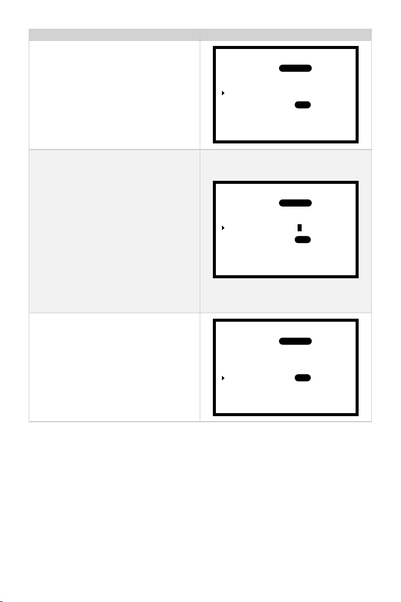
Arbeitsschritte Anzeige auf dem Display
Schritt 5: Durch kurzes Drücken der
Menü-Taste zurückkehren. Mit der Auswahltaste die Option „Voltage Rating“
auswählen.
Schritt 6: Durch kurzes Drücken der
OK-Taste die Einstellung der Nennspannung anwählen. Mit der Auswahltaste
stellen Sie den dreistelligen Wert Ziffer
für Ziffer von links nach rechts ein.
Nach der Einstellung drücken Sie die
OK-Taste, um zu der nächsten Ziffer zu
wechseln. Die momentan einzustellende
Ziffer blinkt. Der Einstellbereich für die
Nennspannung der Batterie beträgt 30 –
99,9 V.
Schritt 7: Durch kurzes Drücken der
Menü-Taste zurückkehren. Mit der Auswahltaste die Option „Hydrogeneration“
auswählen.
Type:
Capacity:
Voltage Rating:
Hydrogeneration:
Undervolt Value:
Type:
Capacity:
Voltage Rating:
Hydrogeneration:
Undervolt Value:
Type:
Capacity:
Voltage Rating:
Hydrogeneration:
Undervolt Value:
0010 Ah
0010 Ah
0010 Ah
30.0 V
ON
30.0 V
30.0 V
ON
30.0 V
30.0 V
ON
30.0 V
Lead-acidLi-ion LiFePO4
OFF
Lead-acidLi-ion LiFePO4
OFF
Lead-acidLi-ion LiFePO4
OFF
70
Page 73
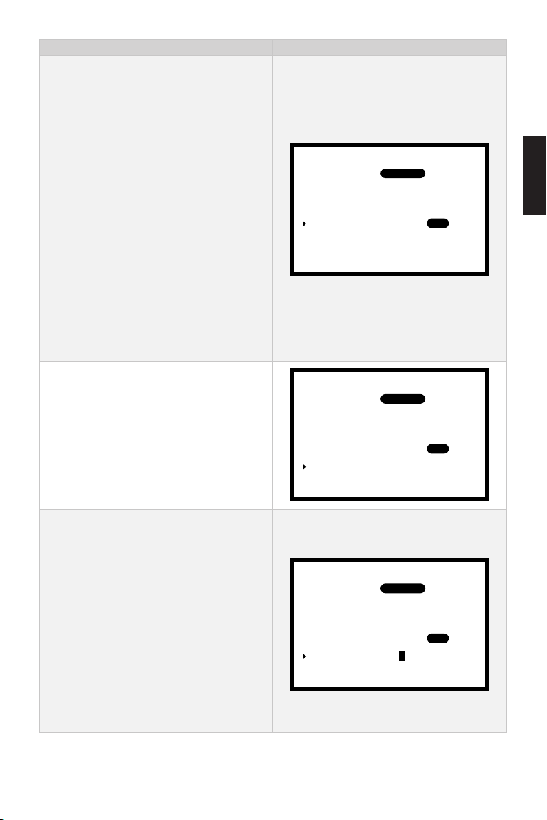
Arbeitsschritte Anzeige auf dem Display
Schritt 8: Durch kurzes Drücken der
OK-Taste die Einstellung der Rekuperation anwählen. Durch kurzes Drücken der
Auswahltaste wird zwischen den Einstellungen „ON“ und „OFF“ gewechselt. Bei
Modellen, die die Funktion Rekuperation
unterstützen, kann sie durch die Einstellung „ON“ aktiviert werden. Bei der
Einstellung „OFF“ ist die Funktion deaktiviert.
Bei Motoren, die keine Rekuperation
unterstützen bzw. wenn keine Kommunikation zwischen dem Motor und der
Batterie besteht, ist die Rekuperation
deaktiviert.
Type:
Capacity:
Voltage Rating:
Hydrogeneration:
Undervolt Value: 30.0 V
0010 Ah
30.0 V
ON
Lead-acidLi-ion LiFePO4
Deutsch
OFF
Schritt 9: Durch kurzes Drücken der
Menü-Taste zurückkehren. Mit der Auswahltaste die Option „Undervolt Value“
auswählen.
Schritt 10: Durch kurzes Drücken der
OK-Taste die Einstellung der Batterieunterspannung anwählen. Mit der Auswahltaste stellen Sie den dreistelligen Wert
Ziffer für Ziffer von links nach rechts
ein. Nach der Einstellung drücken Sie
die OK-Taste, um zur nächsten Ziffer zu
wechseln. Die momentan einzustellende
Ziffer blinkt. Der Einstellbereich für die
Batterieunterspannung beträgt 30 – 99,9
V.
71
Type:
Capacity:
Voltage Rating:
Hydrogeneration:
Undervolt Value: 30.0 V
Type:
Capacity:
Voltage Rating:
Hydrogeneration:
Undervolt Value:
0010 Ah
30.0 V
ON
0010 Ah
30.0 V
ON
30.0 V
Lead-acidLi-ion LiFePO4
OFF
Lead-acidLi-ion LiFePO4
OFF
Page 74
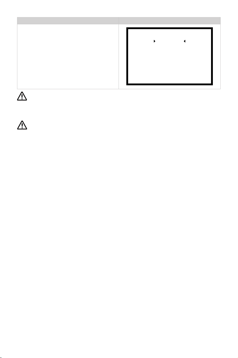
Arbeitsschritte Anzeige auf dem Display
Power Limit
Schritt 11: Menü-Taste kurz drücken, um
in das Setup-Menü zurückzukehren.
Unit Setting
Battery Setting
Throttle
Version
Für Navy-Außenborder und Pod-Antriebe 3.0/6.0 werden Blei-Säure-Batterien
und Lithium-Ionen-Batterien empfohlen. Der Einsatz anderer Batterien kann den
einwandfreien Betrieb des Motors nicht gewährleisten.
Beim Wechsel auf eine Batterie eines anderen Typs muss die neue Batterie kon-
guriert werden.
72
Page 75
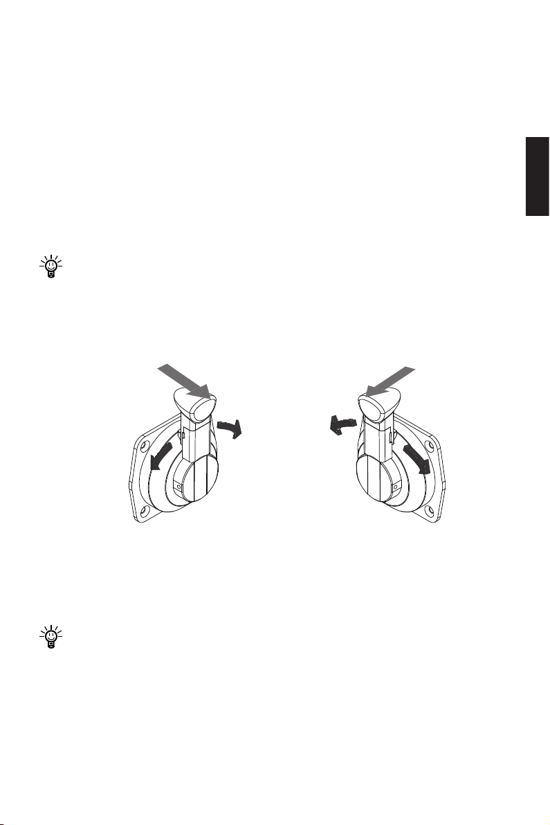
4.2 Bedienung des Gashebels
4.2.1 Leistungseinstellung der Evo seitlichen Fernsteuerung
Die Evo seitliche Fernsteuerung dient hauptsächlich zur Einstellung der Motorleistung.
Nach dem ordnungsgemäßen Anschluss der Batterie die Evo seitliche Fernsteuerung
einschalten und den Motor starten. Den Gashebel von der Position „NULL“ heraus
nach hinten ziehen und anschließend langsam in die Position „Vorwärts“ schwenken,
um die Leistung dadurch zu erhöhen. Siehe Abbildungen 4-1 und 4-2. Wenn sich der
Gashebel in der Position „NULL“ bendet, wird er automatisch verriegelt. Er muss herausgezogen werden, bevor ein Schwenken möglich ist.
Der Gashebel muss in die Position „NULL“ gebracht werden, bevor die Fernsteuerung eingeschaltet wird. Wenn das Symbol für „RESET“ auf dem Display
blinkend erscheint, muss der Gashebel in die Position „NULL“ zurückgesetzt
werden.
NULL NULL
Deutsch
Rückwärts
Abb. 4-1 Backbord Seite (links) Abb. 4-2 Steuerbord Seite (rechts)
Vorwärts
Vorwärts
Rückwärts
4.2.2 Kalibrieren
Falls der Fehlercode E30 auf dem Display erscheint, muss der Gashebel nach den
unten beschriebenen Schritten kalibriert werden.
Falls die Einstellung von Backbord und Steuerbord noch nicht vorgenommen
wurde, muss sie gemäß Kapitel „2.5 Einstellung von Backbord und Steuerbord“
noch vor der Kalibrierung des Gashebels durchgeführt werden.
73
Page 76
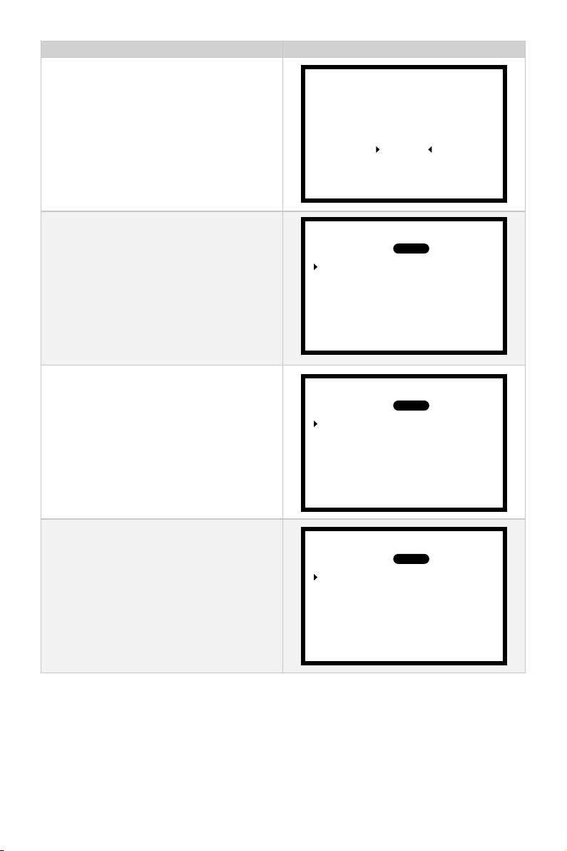
Arbeitsschritte Anzeige auf dem Display
Schritt 1: Im eingeschalteten Zustand
durch langes Drücken der Menü-Taste
in das Setup-Menü gelangen. Mit der
Auswahltaste den Menüpunkt „Throttle“
wählen. Mit der OK-Taste bestätigen, um
zu den Einstellungen des Gashebels zu
gelangen.
Power Limit
Unit Setting
Battery Setting
Throttle
Version
Schritt 2: Mit der Auswahltaste den
Menüpunkt „Calibration“ wählen. Mit der
OK-Taste bestätigen, um die Kalibrierung
des Gashebels zu starten.
Schritt 3: Den Gashebel in die Vorwärts-Richtung bis zum Anschlag
schwenken und die OK-Taste drücken.
Schritt 4: Den Gashebel in die NULL-Position bringen. Anschließend die OK-Taste
drücken.
Handle Side:
Calibration
Push forward to the end
Handle Side:
Calibration
Push to the neutral
Handle Side:
Calibration
Push backward to the end
PORT
then press OK
PORT
then press OK
PORT
then press OK
STBD
STBD
STBD
74
Page 77
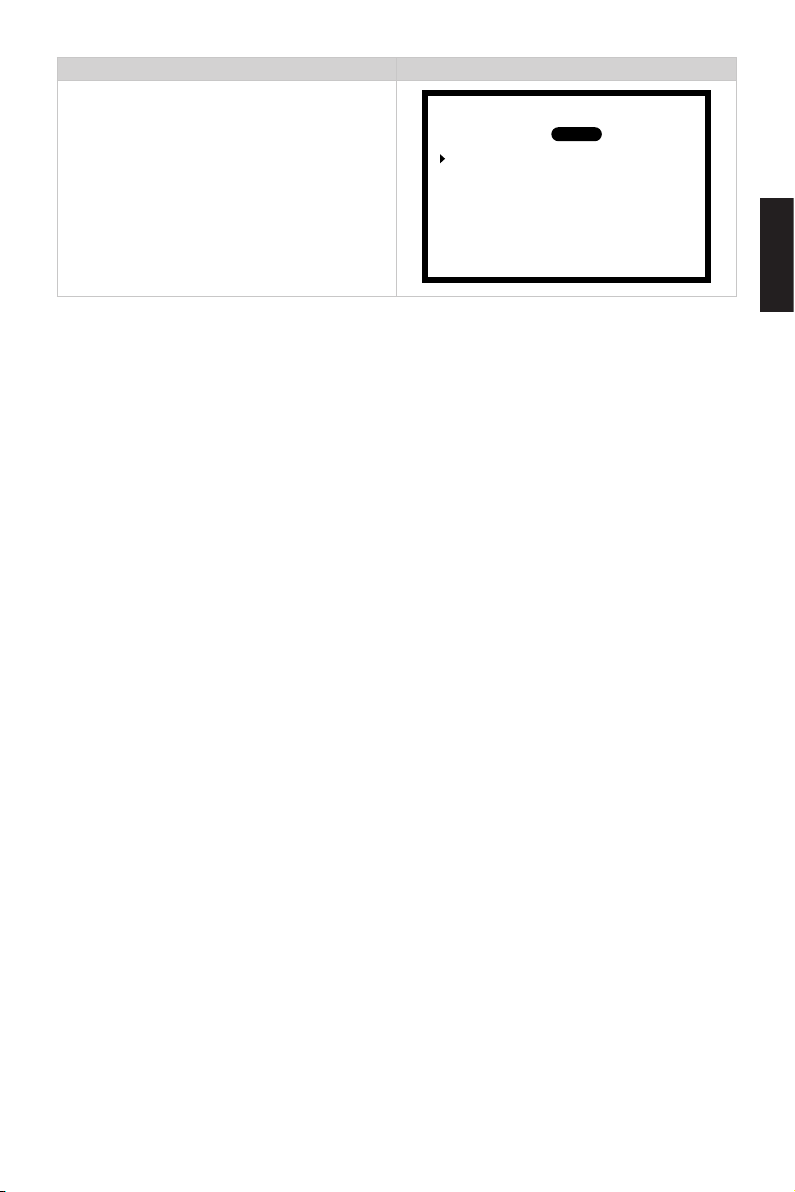
Arbeitsschritte Anzeige auf dem Display
Schritt 5: Den Gashebel in die Rückwärts-Richtung bis zum Anschlag
schwenken. Anschließend die OK-Taste
drücken. Nach der Kalibrierung wechselt
das Display automatisch in das Hauptmenü zurück.
Handle Side:
Calibration
Calibration complete.
PORT
Press OK
STBD
Deutsch
75
Page 78
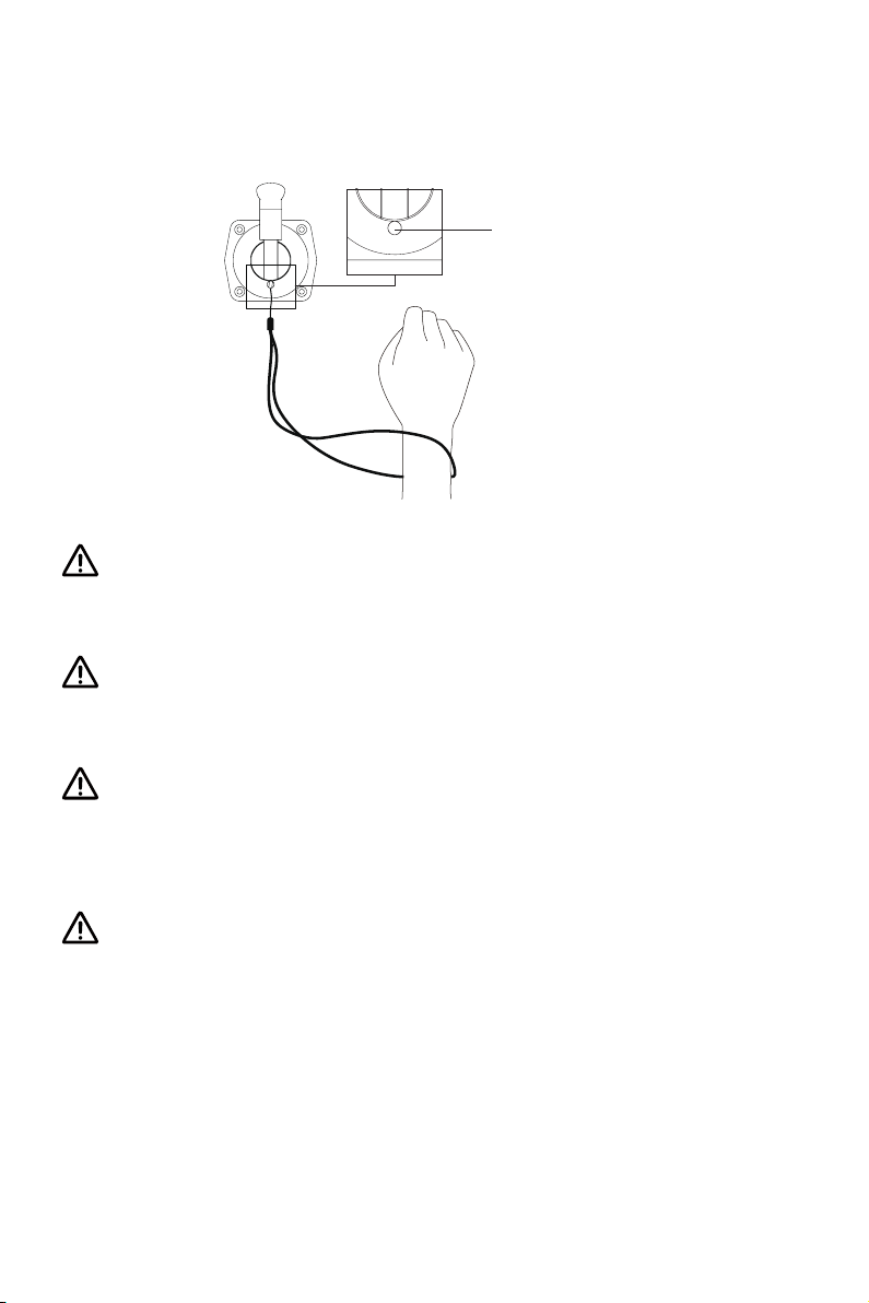
4.3 Verwendung des Reißleinenschalters
Die Reißleine um Ihr Handgelenk legen oder an Ihrer Schwimmweste befestigen. Im
Notfall kann der Motor durch Ausreißen der Reißleine gestoppt werden.
Vorgesehene Position für
den Reißleinenschalter
Abb. 4-3
Den Reißleinenschalter nach Ausschalten des Motors herausziehen und gut aufbewahren. Wenn der Reißleinenschalter stecken bleibt, wird eine angeschlossene Batterie weiter entladen.
Nachdem der Motor angeschlossen ist, muss der Reißleinenschalter vor dem
Einschalten der Stromversorgung eingesteckt werden, da der Motor sonst nicht
einwandfrei betrieben werden kann.
Der Reißleinenschalter erzeugt ein Magnetfeld. Zwischen Personen mit Herzschrittmachern oder implantierten Defibrillatoren, magnetischen Karten bzw.
anderen magnetischen Gegenständen und dem Schalter muss ein Sicherheitsabstand von mindestens 50 cm eingehalten werden.
Das Magnetfeld des Reißleinenschalters beeinusst elektrische Messgeräte und
muss daher von ihnen ferngehalten werden.
76
Page 79
4.4 Kontrolle vor dem Betrieb
1. Vor dem Einschalten der Stromversorgung sicherstellen, dass die Evo seitliche
Fernsteuerung und das Lenkrad an ihren richtigen Positionen eingebaut sind.
2. Sicherstellen, dass sich die Evo seitliche Fernsteuerung problemlos bedienen lässt.
3. Vor dem Anschluss der Batterie sicherstellen, dass die Verbindungskabel keine
Wackelkontakte oder Beschädigungen aufweisen.
4. Bei Außenbordern der Navy-Serie oder Pod-Antrieben die einwandfreie Funktion
des Hauptschalters kontrollieren. Nach der Kontrolle den Hauptschalter wieder ausschalten.
5. Sicherstellen, dass die Version-Einstellung der Evo seitlichen Fernsteuerung mit
dem Modell des eingesetzten Motors übereinstimmt.
6. Sicherstellen, dass die Batterie ausreichend geladen ist.
7. Bei der Verwendung von Fremdbatterien muss die Batterie konguriert werden.
Den Motor erst starten, wenn sich der Propeller im Wasser bendet, denn dre-
hende Propeller können Verletzungen verursachen.
Falls die Verbindungskabel mit Wasser in Kontakt gekommen sind, müssen sie
vor der Verwendung getrocknet werden.
Deutsch
Sollte die Version nicht stimmen, kann sie wie im Kapitel
border auswählen“
beschrieben angepasst werden.
77
2.4 „Kompatible Außen-
Page 80
4.5 Motor starten
1. Die notwendigen Kontrollen durchführen.
2. Den Reißleinenschalter von der Evo seitlichen Fernsteuerung abnehmen.
3. Den Gashebel in die NULL-Position stellen.
4. Die Batterie mit dem Motor verbinden.
5. Bei der Kombination mit Außenbordern muss der Motor mit einem passenden Winkel befestigt werden.
6. Bei der Kombination mit Außenbordern der Navy-Serie oder Pod-Antrieben muss
der Hauptschalter eingeschaltet werden. Bei E-Serie-Batterien die Stromversorgung
durch Drücken der EIN/AUS-Taste der Batterie einschalten.
7. Das Display wird durch Drücken der EIN/AUS-Taste eingeschaltet und zeigt anschließend das Hauptmenü.
8. Ggf. die benutzerdenierten Einstellungen und die Batterie-Einstellungen vornehmen.
9. Die Reißleine des Sicherheitsschalters um das Handgelenk legen oder an der
Schwimmweste befestigen. Danach den Reißleinenschalter an die richtige Position
der Evo seitlichen Fernsteuerung legen.
10. Den Gashebel von der NULL-Position wegziehen. Durch langsames Schwenken
des Hebels wird der Motor gestartet.
Falls „Equipment oine“ auf dem Display erscheint:
1) Kontrollieren, ob der Reißleinenschalter richtig angebracht ist.
2) Verbindungskabel falsch angeschlossen. Die Verbindungskabel mit dem richtigen Anschluss verbinden. Der mit „ “ gekennzeichnete Anschluss muss an
den Motor angeschlossen werden. Der Anschluss mit dem Symbol „ “ muss
mit dem Bedienpanel verbunden werden.
3) Wenn die Verbindungskabel mit den richtigen Anschlüssen verbunden sind,
dann liegt die Störung bei der Kommunikation zwischen dem Bedienpanel und
dem Gashebel. Das entsprechende Kabel auf festen Sitz und Beschädigungen
kontrollieren.
78
Page 81

4.6 Motor stoppen
Im Normalfall soll der Motor wie unten beschrieben ausgeschaltet werden.
1. Den Gashebel in die NULL-Position stellen. Der Hebel wird automatisch verriegelt.
2. Warten bis der Motor stillsteht. Den Reißleinenschalter von der Evo seitlichen Fernsteuerung entfernen.
3. Durch langes Drücken der EIN/AUS-Taste die Evo seitliche Fernsteuerung ausschalten.
4. Bei der Kombination mit Außenbordern der Navy-Serie oder Pod-Antrieben muss
der Hauptschalter ausgeschaltet werden. Bei E-Serie-Batterien die Stromversorgung
durch Drücken der EIN/AUS-Taste der Batterie ausschalten.
5. Bei Außenbordern diese aus dem Wasser heben bzw. ausbauen.
Wenn eine der folgenden Situationen vorkommt, wird der Motor gestoppt.
1) Der Gashebel bendet sich in der NULL-Position.
2) Der Reißleinenschalter bendet sich nicht an seiner vorgesehenen Position.
3) Bei der Kombination mit Außenbordern der Navy-Serie oder Pod-Antrieben ist
der Hauptschalter ausgeschaltet.
Deutsch
4) Evo seitliche Fernsteuerung hat keine Verbindung zum Motor.
5) Die Verbindung zwischen der Batterie und dem Motor ist unterbrochen.
6) Die Steuerung hat eine Störung (Motor blockiert oder Batterieunterspannung
wurde erkannt).
Im Notfall kann der Motor durch folgende Bedienung ausgeschaltet werden:
1) Den Reißleinenschalter abziehen.
2) Den Gashebel in die NULL-Position stellen.
79
Page 82
5 Gewährleistung
Die Fa. ePropulsion übernimmt Garantie für alle durch autorisierte Händler erworbenen ePropulsion Produkte. Der Garantieumfang beinhaltet kostenlosen Umtausch von
Produkten, die schwerwiegende Qualitätsmängel aufweisen, Vertragsbedingungen
nicht erfüllen bzw. kostenlosen Reparatur- oder Umtauschservice von fehlerhaften
oder fehlenden Bauteilen. Die Festlegung der Garantiebedingungen dient zum Schutz
der Verbraucherrechte.
5.1 Garantiebedingungen
ePropulsion bietet für seine Produkte ab dem Kaufdatum für einen bestimmten
Zeitraum Garantieleistungen. Treten Qualitätsmängel innerhalb der Garantiefrist auf,
kann der Benutzer seinen Garantieanspruch gegenüber der Fa. ePropulsion geltend
machen.
Produkt/Bauteil Frist
Evo Fernsteuerung für den
seitlichen Einbau
Reparierte oder umge-
tauschte Bauteile
Um zu überprüfen, ob die Garantiebedingungen erfüllt sind, muss der Benutzer
die der Verpackung beiliegende Garantiekarte ausfüllen.
Das Typenschild des Produkts darf nicht beschädigt werden. Die Seriennummer
muss dem Typenschild entnommen werden. Das Typenschild darf auf keinen
Fall vom Produkt entfernt werden. Für Produkte ohne das Original-Typenschild
2 Jahre ab dem Kaufdatum (nur bei nicht-gewerblicher Nutzung)
Drei Monate ab dem Datum der Reparatur oder des
Umtauschs.
Anmerkung:
1. Wenn diese drei Monate die Original-Garantiefrist
nicht überschreiten, dann bleibt die Garantie für diese
reparierten bzw. umgetauschten Bauteile für 1 Jahr
(ab dem Kaufdatum des Produkts) gültig.
2. Wenn diese drei Monate die Original-Garantiefrist
überschreiten, dann bleibt die Garantie für diese reparierten bzw. umgetauschten Bauteile für 3 Monate
(ab dem Servicedatum der Reparatur oder des Umtauschs) gültig.
80
Page 83

erlischt der Garantieanspruch gegenüber der Fa. ePropulsion.
Die Garantie kann nur gewährleistet werden, wenn die vom Benutzer gemachten
Angaben richtig und vollständig sind.
Der Benutzer muss die gültige Seriennummer seines Produkts, die ausgefüllte
Garantiekarte sowie den von einem autorisierten Vertragshändler ausgestellten
Kaufbeleg einreichen.
Das gültige Kaufdatum wird durch den Original-Kaufbeleg des ersten Käufers bestimmt.
Die Garantiekarte darf nicht weitergegeben werden und wird bei Verlust nicht ersetzt.
5.2 Von der Garantie ausgenommen
Das Produkt muss beim Einschicken zur Reparatur ausreichend verpackt sein. Es wird
empfohlen, die Original-Verpackung von ePropulsion zu verwenden. Wenn Bauteile
durch unzureichende Verpackung beim Einschicken beschädigt werden, unterliegen
diese Bauteile nicht den vereinbarten Garantieleistungen.
Darüber hinaus werden durch folgende Situationen verursachte Störungen oder
Schäden nicht als Garantiefall anerkannt, auch wenn die Garantiefrist noch nicht abgelaufen ist:
• Bedienung, die mit dieser Bedienungsanleitung nicht konform ist.
• Unfälle, unsachgemäße Handhabung, absichtliche Fehlnutzung, schwere
physikalische Defekte oder eigenmächtige Reparaturen.
• Herunterfallen, unsachgemäße Instandhaltung oder Lagerung.
Für normalen Verschleiß, der die Funktionen des Produkts nicht beeinusst, ist
ebenfalls keine Garantieleistung möglich.
Deutsch
Für Verschleißteile wird keine Garantie geleistet.
5.3 Abwicklung eines Garantiefalls
Bei der Feststellung von Qualitätsmängeln können Sie gemäß dem folgenden Verfahren Ihren Garantieanspruch bei einem Vertragshändler geltend machen:
1. Die Garantiekarte richtig und vollständig ausfüllen. Die Karte zusammen mit
einem gültigen Kaufbeleg bei einem autorisierten ePropulsion Vertragshändler
81
Page 84

einreichen. Für einen Garantiefall sind folgende Unterlagen notwendig: die
Garantiekarte, die Seriennummer des Produkts und der Kaufbeleg.
2. Nach der Bestätigung des Garantieanspruchs geben Sie das fehlerhafte Produkt
bei einer autorisierten Servicestelle ab. Achten Sie darauf, dass das Typenschild
unbeschädigt ist.
3. Der Vertragshändler der Fa. ePropulsion kümmert sich um die Fehlerdiagnose
und die Reparatur des defekten Bauteils oder veranlasst einen Umtausch.
4. Bei einem Garantiefall müssen Sie keine Kosten für die Reparatur oder den
Umtausch übernehmen. Sämtliche Versandkosten während der Abwicklung
muss jedoch der Benutzer selbst tragen.
5. Nach sorgfältigen Prüfungen führen die Vertragshändler der Fa. ePropulsion
Reparaturen oder Umtausch der fehlerhaften oder defekten Bauteile durch.
6. Bei einer Ablehnung des Garantieanspruchs erhalten Sie von Ihrem ePropulsion
Vertragshändler für die fälligen Reparaturarbeiten einen Kostenvoranschlag, in
dem auch die gesamten Versandkosten enthalten sind. Der Vertragshändler führt
die Reparatur erst nach dem Erhalt Ihrer Bestätigung durch.
Nach dem Ablauf der Garantiefrist gewährleisten wir unseren Kunden, ihre Reparaturen zu einem günstigsten Preis von Vertragshändlern der Fa. ePropulsion
durchführen zu lassen.
Page 85

Page 86

Thanks for reading this user manual.
If you have any concerns or find any problems while
reading, please don't hesitate to contact us. We are
delighted to offer service for you.
Vielen Dank, dass Sie diese Bedienungsanleitung
gelesen haben.
Wenn Sie Fragen haben oder beim Lesen Unklarheiten
aufgekommen sind, zögern Sie bitte nicht, uns zu
kontaktieren. Wir freuen uns, Ihnen behilflich sein zu
können.
Guangdong ePropulsion Technology Limited
Website: www.epropulsion.com
Email: [email protected]
 Loading...