

Page 1
English
Deutsch
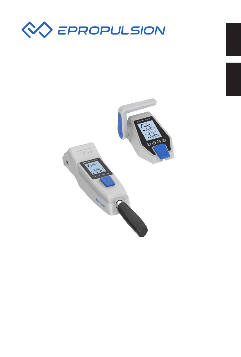
Evo Control System Installation Guide
Installationsanleitung Evo Steuerungssystem
2021.12 Version 1.1
Copyright © 2020-2021 ePropulsion All Rights Reserved
Page 2

Page 3
Acknowledgement
Thanks for choosing ePropulsion products, your trust and support in our company are
sincerely appreciated. We are dedicated to providing high-performance products and
accessories.
Welcome to visit www.epropulsion.com and contact us if you have any concerns.
Using This Manual
Before use of the product, please read this user manual thoroughly to understand the
correct and safe operations. By using this product, you hereby agree that you have
fully read and understood all contents of this manual. ePropulsion accepts no liability
for any damage or injury caused by operations that contradict this manual.
Due to ongoing optimization of our products, ePropulsion reserves the rights of
constantly adjusting the contents described in the manual. ePropulsion also reserves
the intellectual property rights and industrial property rights including copyrights,
patents, logos and designs, etc.
This manual is subject to update without prior notice, please visit our website
www.epropulsion.com for the latest version. If you find any discrepancy between your
products and this manual, or should you have any doubts concerning the product or
the manual, please visit www.epropulsion.com.
ePropulsion reserves the rights of final interpretation of this manual.
This manual is multilingual, in case of any discrepancy in the interpretation of
different language versions, the English version shall prevail.
English
Symbols
The following symbols will help to acquire some key information.
Important instructions or warnings
Useful information or tips
1
Page 4
Product Identification
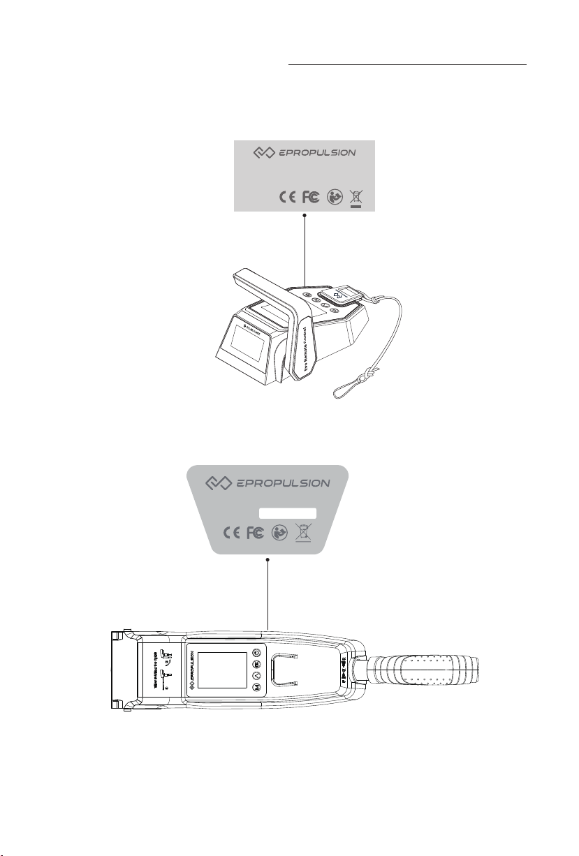
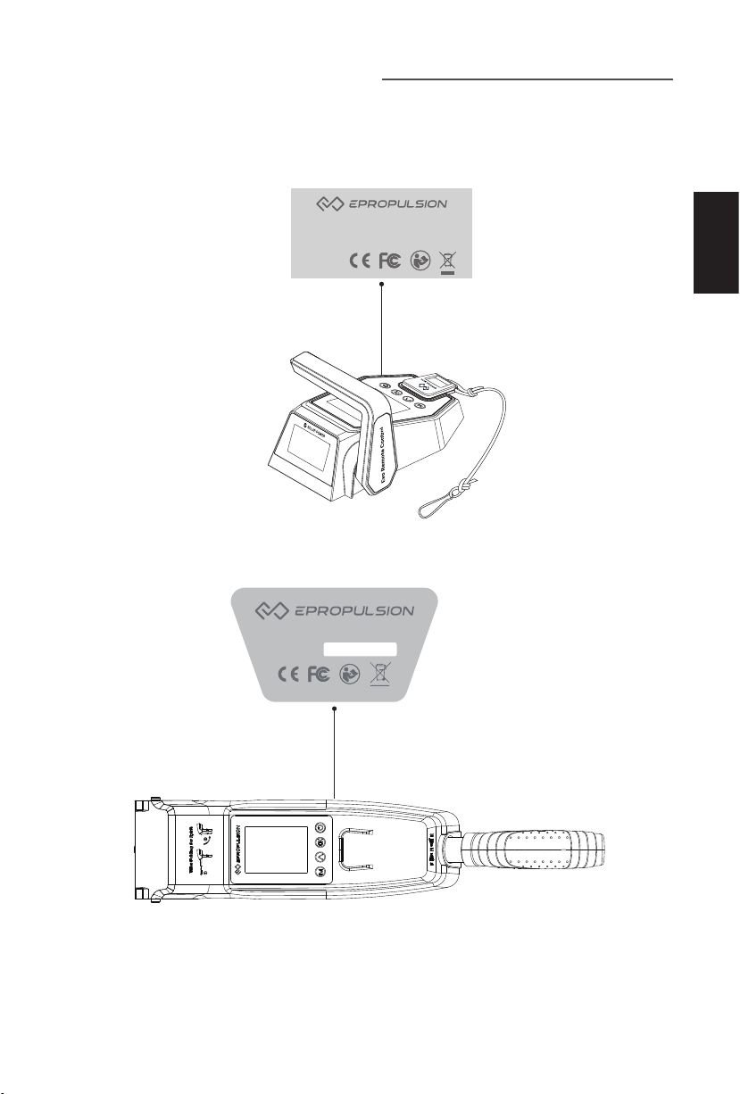
Below picture indicates the serial numbers of Evo Remote Control and Evo Tiller.
Please note the position of the serial numbers and record them for access to
warranty service and other after-sale services.
Model: Evo Remote Controller
Serial No.: DERCXXXXXXX
Figure 0-1
Model: Evo Tiller
Serial No.:
Figure 0-2
2
Page 5

Table of content
Acknowledgement ..................................................................................... 1
Using This Manual ..................................................................................... 1
Symbols .................................................................................................... 1
Product Identification ................................................................................ 2
1 Product Overview ................................................................................... 4
1.1 In the Package ........................................................................................ 4
1.2 Parts and Diagrams ................................................................................. 5
1.3 Specification ............................................................................................ 6
2 Installation ............................................................................................. 7
2.1 Mounting the Evo Remote Control ......................................................... 7
2.2 Mounting the Evo Tiller ........................................................................... 7
2.2.1 Mounting on the SPIRIT 1.0 Evo ...................................................7
2.2.1 Mounting on the NAVY 3.0 Evo/NAVY 6.0 Evo ............................ 8
3 Wiring ..................................................................................................... 9
3.1 Connecting the remote control and the outboard ................................. 9
3.2 Connecting the tiller and the outboard .................................................. 9
4 Charging ............................................................................................... 10
4.1 Charging by solar power ....................................................................... 10
4.2 Charging by wired connection .............................................................. 10
English
5 Use of Kill Switch .................................................................................. 12
6 Warranty .............................................................................................. 13
6.1 Warranty Policies ...................................................................................13
6.2 Out of Warranty ......................................................................................14
6.3 Warranty Claim Procedures .................................................................. 14
3
Page 6
1 Product Overview
The Evo Remote Control and Evo Tiller are used for starting and stopping the
outboard motor, adjusting the speed of the motor, configuring the battery parameters,
displaying the system information and messages, etc. The Evo Remote Control
is powered by either solar power or the built-in lithium battery, but the Evo Tiller is
powered by connecting to the outboard with a communication cable. Evo Remote
Control wirelessly or wiredly communicates with the outboard control system built
in the main outboard motor, and Evo Tiller can only wiredly communicate with the
outboard. The Evo Tiller itself owns the steering capability, while using the Evo
Remote Control, it requires an additional steering wheel to help steer.
1.1 In the Package
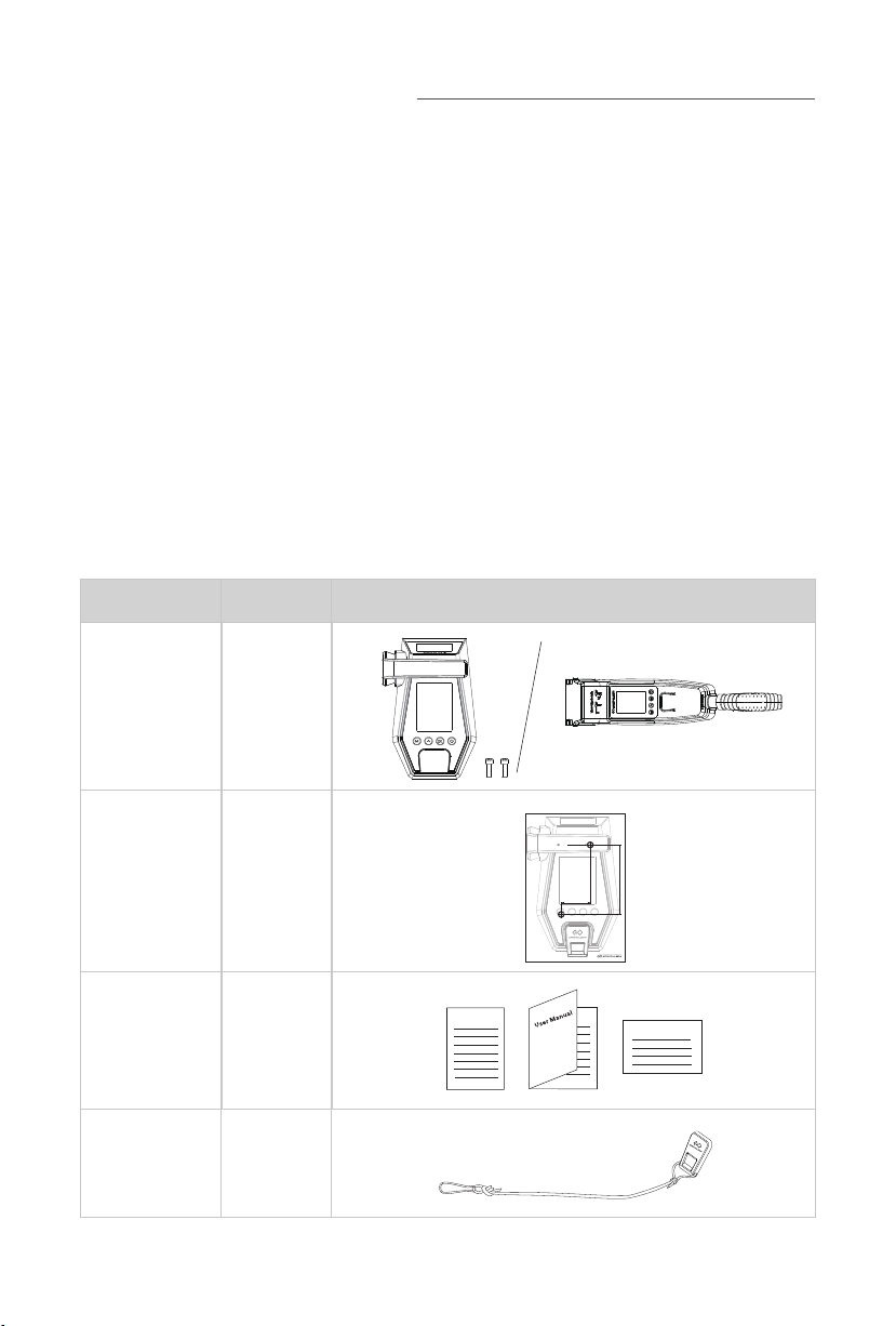
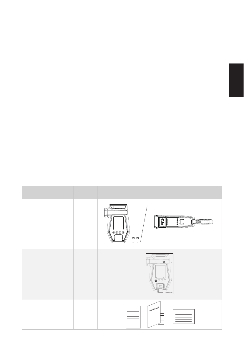
When you receive a set of Evo Remote Control or Evo Tiller, unpack its package
and check if all the items below are included in the package. If there is any loss or
transport damage, please contact your dealer immediately.
Items Qty./Unit Figure
Evo Remote
Control / Evo
Tiller
1 set
Fixing Guide
(Only provided
with Remote
1 piece
Control)
User Manual,
Warranty Card
& Invitation
1 set
Card
Kill Switch 2 pieces
4
Warranty
Navy 6.0R
Fixing Guide
For Remote Controller
Plotting Scale - 1:1
Screw Size - M6×12mm
2× 6mm
98mm
41mm
Room 702
Kowloon Bldg
555 Nathan Rd
Kowloon, Hong Kong
www.epropulsion.com
Invitation Card
Page 7
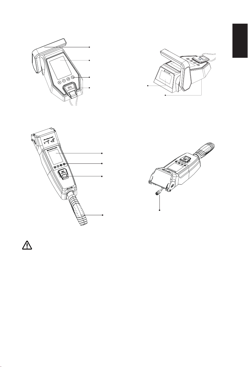
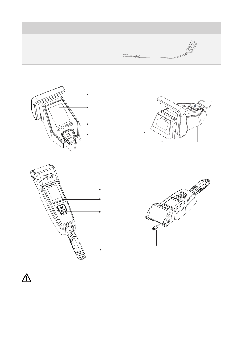
1.2 Parts and Diagrams
Throttle Handle
Display Panel
Buttons
Kill Switch
Figure 1-1
Display Panel
Buttons
Kill Switch
Throttle Handle
English
Solar Panel
Communication Port
(Bottom)
Communication Port
Figure 1-2
When replacing the membrane switch panel, you cannot use alcohol cleaners to
clean the lens. Using alcohol cleaners may cause the lens to crack.
5
Page 8

1.3 Specification
Evo Remote Control
Communication Wireless / Wired
Communication Distance ≤10 m
Weight 0.65 kg / 1.43 lbs.
Dimension (L x W x H)
Evo Tiller
Communication Wired
Weight 1.1 kg / 2.43 lbs.
Dimension (L x W x H)
193 mm x 130 mm x 112 mm /
7.6” x 5.1” x 4.4”
513 mm x 90 mm x 114 mm /
20.2” x 3.5” x 4.5”
6
Page 9
2 Installation
2.1 Mounting the Evo Remote Control
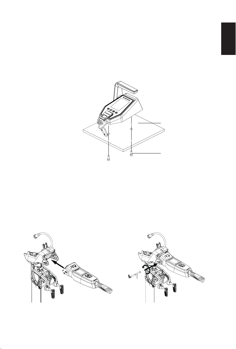
Refer to the remote control fixing guide to punch holes on the ship board, and use the
screws to lock the remote control box as shown in Figure 2-1.
Hull
Screw
Figure 2-1
2.2 Mounting the Evo Tiller
English
2.2.1 Mounting on the SPIRIT 1.0 Evo
1. Install the tiller to the machine (Figure 2-2).
2. Insert the handle shaft into the hole to the end and lock it counter-
clockwise (Figure 2-3).
Tiller
Shaft
Figure 2-2
7
Figure 2-3
Page 10
2.2.1 Mounting on the NAVY 3.0 Evo/NAVY 6.0 Evo
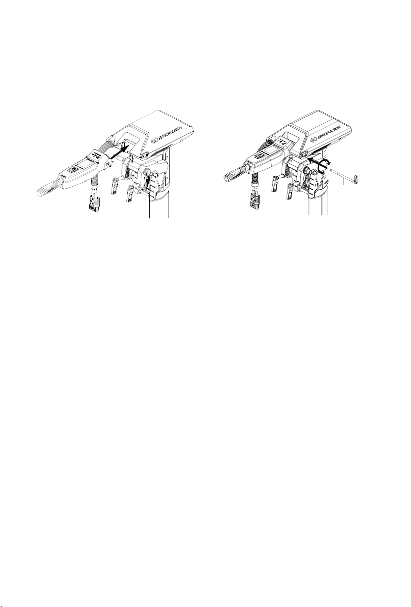
1. Install the tiller to the machine (Figure 2-4).
2. Insert the handle shaft into the hole to the end and lock it clockwise (Figure
2-5).
Tiller Shaft
Figure 2-4
Figure 2-5
8
Page 11
3 Wiring
3.1 Connecting the remote control and the outboard
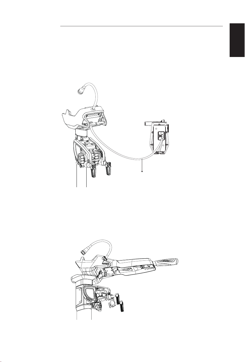
If the remote control needs to be connected with the machine by wire, a
communication cable is needed to connect the machine and the remote control
Communication port (Figure 3-1).
Communication Cable
Figure 3-1
English
3.2 Connecting the tiller and the outboard
After mounting the tiller, you need to connect the communication port of the tiller to
the communication port of the machine (Figure 3-2).
Figure 3-2
9
Page 12
4 Charging
The Evo Remote Control has a built-in lithium battery for power supply. The battery
will be charged automatically under normal use: get charged by solar power or wired
connection. The Evo Tiller does not have a built-in battery and needs to be connected
to the machine.
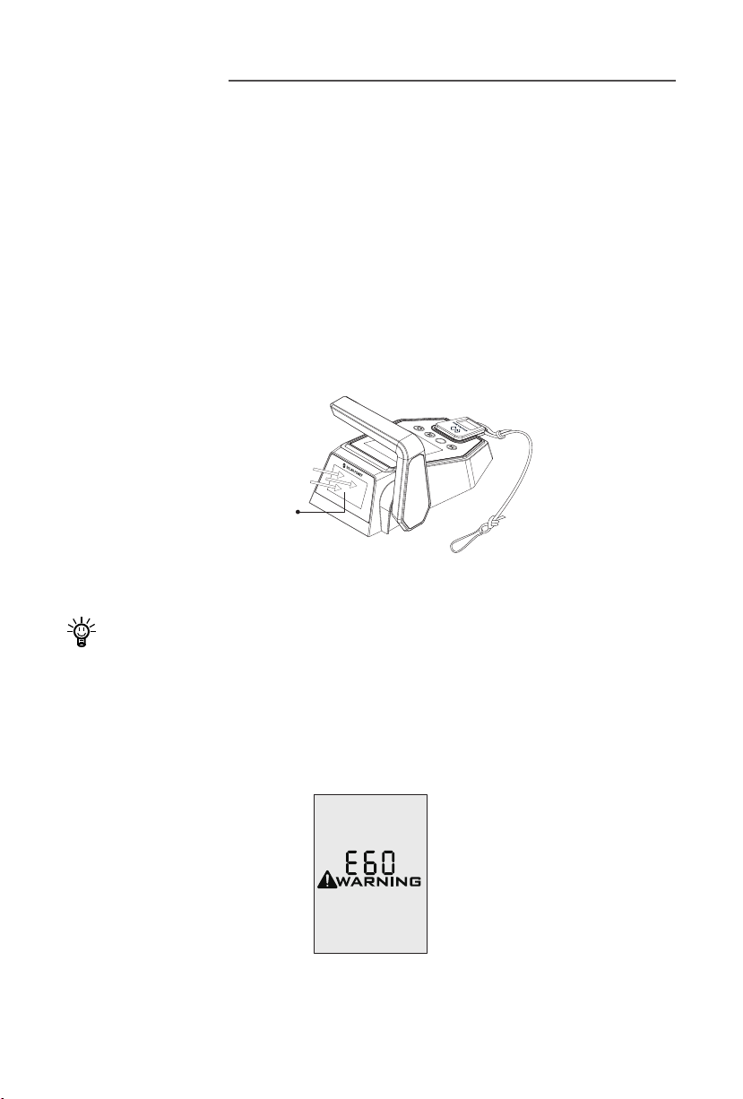
4.1 Charging by solar power
When the solar panel receives enough sunshine, it will generate electricity to charge
the built-in lithium battery. While charging the battery by solar power, it’s suggested
to face the solar panel of the Remote Control toward sunlight to get better charging
effect.
^
Solar Panel
(Face the Sun)
Figure 4-1
It’s recommended to charge the Remote Control by solar power.
4.2 Charging by wired connection
If the Evo Remote Control can’t get enough solar power for a long time, the battery
level will run out. In this case, a warning message with an error code E60 (Figure 4-2)
will display on the LCD panel to remind you to charge the Remote Control.
Figure 4-2
10
Page 13
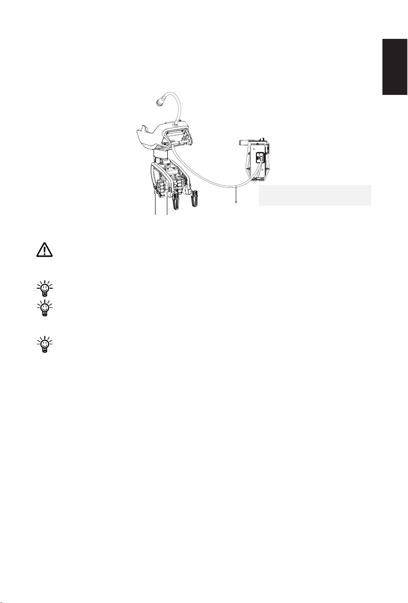
Please follow the below steps to charge the Remote Control by wired connection.
First, connect the Remote Control to the outboard motor by a communication cable
first (Figure 4-3);
Then, connect the outboard motor to the battery.
* The communication cable needs
to be purchased separately.
Communication Cable
Figure 4-3
During long-term storage, ensure to charge the Remote Control battery every 6
months to avoid over-discharge.
After long-term storage, charge the Remote Control before use.
The communication cable is not included in this package. Please purchase one
from your dealer if you choose this charging method.
English
It’s recommended to switch off the Remote Control while connecting the
communication cable. When the Remote Control is switched on while charging,
as the outboard main part and Remote Control are in communication, the
working outboard motor will stop once the communication cable disconnects.
11
Page 14
5 Use of Kill Switch
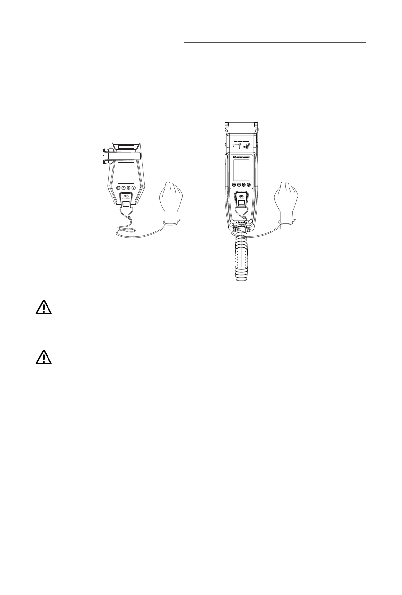
• Locate the kill switch to the right place on the Evo Remote Control / Evo
Tiller and tie its lanyard to your wrist or life jacket.
• Stop the outboard in emergency by detaching the kill switch.
• To run the motor again, first attach the kill switch then start the motor.
Figure 5-1
The kill switch generates magnetic field. Keep it 50cm / 20inches away from
medical implants like pacemakers and magnetic cards (e.g. credit card) as well
as other magnetic media.
The magnetic field of the kill switch may interfere with some electronic
instruments. Keep it away from these electronic instruments.
12
Page 15
6 Warranty
The ePropulsion limited warranty is provided for the first end purchaser of an
ePropulsion product. Consumers are entitled to a free repair or replacement of
defective parts or parts which do not conform with the sales contract. This warranty
operates in addition to your statutory rights under your local consumer law.
6.1 Warranty Policies
ePropulsion warrants its products to be free of defects in material and workmanship
for a limited period since the date of purchase. Once a fault is discovered, the user
has the right to make a warranty claim under the ePropulsion warranty policies.
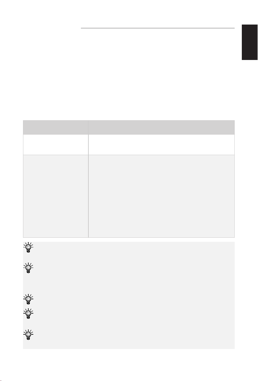
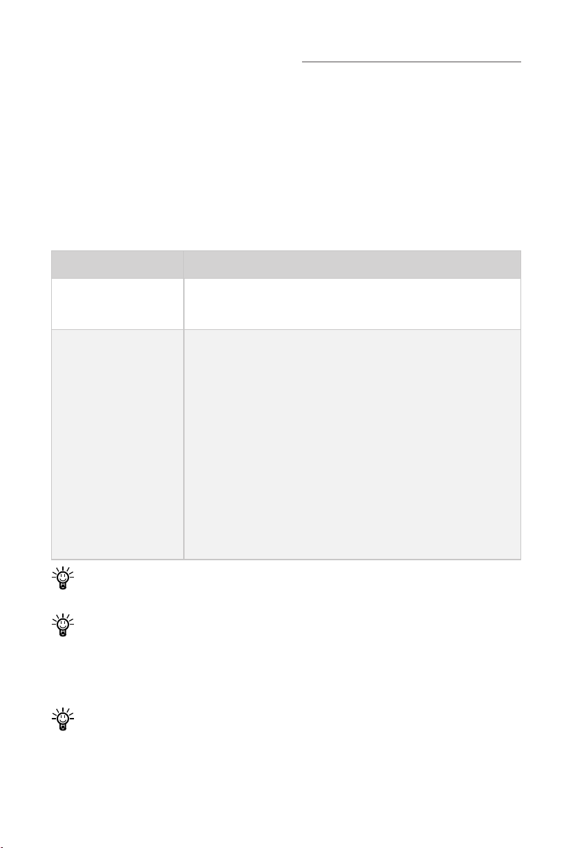
Product Warranty Expiry Date
English
Evo Remote Control /
Evo Tiller
Components
have been
repaired or replaced
In order to validate the warranty, users are required to fill in the Warranty Card in
the package in advance.
Keep the product label in intact state and record the serial number on the label.
Never tear the label off the product. An ePropulsion product without the original
product label will not be applicable to warranty services provided by ePropulsion.
The warranty is valid only when the information is correct and complete.
Free warranty is only validated upon the presentation of legal serial number,
Warranty Card, and evidence of purchase from an authorized ePropulsion dealer.
Two years after the date of purchase.
Three months since the date of maintenance.
Note:
1. If the three-month period overlaps with the original
warranty period, the warranty against these replaced or
repaired parts still expires two years after the date of
purchase.
2. If the three-month period exceeds the original warranty
period, the repaired or replaced parts continue applying
to warranty during the extended period.
Valid date of purchase should be established by the first-hand purchaser with
original sales slip.
13
Page 16

Free warranty is not transferable and will not be reissued.
Within the limits of the applicable laws, the warranty policies of ePropulsion may
update without prior notice. The latest version is available at our website www.
epropulsion.com.
6.2 Out of Warranty
Make sure the product is properly packed during delivery, the original ePropulsion
package is recommended. If the product got further damaged due to improper
packing during delivery, the furtherly damaged part will be deemed as out of warranty
coverage.
In addition, faults or damages caused by the following reasons are also excluded
from warranty scope within the covered period:
• Any improper operation contradicts the user manual.
• Accident, misuse, wishful abuse, physical damage overcharging, liquid damage or
unauthorized repair.
• Dropping, improper care or storage.
You should be noted that minor faults like normal wear and tear that pose no
influence on the intended function of the product are also not covered by the
warranty.
Consumables are out of warranty scope.
6.3 Warranty Claim Procedures
If you find your product defective, you can make a claim to your dealer following
below procedures:
1. Fill in the Warranty Card correctly and completely in advance. Then make your
warranty claim by sending it to your authorized ePropulsion service partner
together with valid proof of purchase. Usually these documents are required
when making a warranty claim: the Warranty Card, ex-factory serial number, and
evidence of purchase.
2. Send the defective product to your authorized ePropulsion service point after
getting the confirmation. Note that the label should be kept intact. You can
also deliver the product to your authorized ePropulsion dealer after getting
confirmation.
14
Page 17
1. The defective components or parts will be either repaired or replaced according
to the diagnosis made by the ePropulsion authorized service partner.
2. If your warranty claim is accepted, the equipment will be repaired or replaced free
of cost. Note that any delivery cost incurred in the process is at your charge.
3. After careful examination and confirmation by ePropulsion authorized dealer, the
defective or faulty components will be repaired or replaced with brand new ones
against the actual condition.
4. In case your warranty claim is rejected, an estimated repair charge with round trip
delivery cost will be sent for confirmation. ePropulsion authorized service point
will conduct maintenance accordingly only after your confirmation.
If warranty expires, you can still enjoy maintenance services from authorized
ePropulsion service partners with minimum maintenance charge.
English
15
Page 18

Vorwort
Für Ihren Kauf von ePropulsion Produkten sowie Ihr Vertrauen in unser Unternehmen
bedanken wir uns herzlich. Wir haben uns zum Ziel gesetzt, leistungsstarke und zuverlässige Produkte und Zubehör herzustellen.
Für weitere Informationen besuchen Sie unsere Website: www.epropulsion.com.
Über diese Bedienungsanleitung
Vor der Verwendung des Produkts lesen Sie bitte sorgfältig diese Bedienungsanleitung (nachfolgend „Handbuch“ genannt), um eine ordnungsgemäße und sichere Bedienung zu gewährleisten. Mit der Verwendung dieses Produkts erklärt der Benutzer,
dieses Handbuch vollständig gelesen und verstanden zu haben. ePropulsion übernimmt keine Verantwortung für Personen- und Sachschäden, die durch Nichtbeach-
tung des Handbuchs entstehen.
Zur Verbesserung unserer Produkte behalten wir uns das Recht vor, Inhalte dieses Handbuchs zu ändern. Ebenfalls gehören alle geistigen Eigentumsrechte, einschließlich, jedoch nicht beschränkt auf alle Urheberrechte, Patente, Markenzeichen
und Designs, ausschließlich der Fa. ePropulsion.
Dieses Handbuch unterliegt unregelmäßigen Änderungen. Für die aktuelle Version
besuchen Sie bitte unsere Website: www.epropulsion.com. Falls Sie Abweichungen
zwischen Ihrem Produkt und den Beschreibungen dieses Handbuchs feststellen
oder Fragen zum Produkt oder Handbuch haben, besuchen Sie bitte unsere Website www.epropulsion.com oder nehmen Sie Kontakt mit uns auf. Das alleinige Recht
für die Erklärung zum Inhalt dieses Handbuchs ist ePropulsion vorbehalten. Dieses
Handbuch ist in verschiedenen Sprachen vorhanden. Bei Abweichungen dient die
englische Version als Orientierung.
Symbole
Beim Lesen dieses Handbuchs beachten Sie bitte die folgenden Symbole:
Wichtige Hinweise und Warnungen
Nützliche Informationen zum Gebrauch
16
Page 19
Produktkennzeichnung
Das folgende Bild zeigt die Seriennummern des Evo Steuerungssystems und der Evo
Pinne. Bitte merken Sie sich, wo die Seriennummern zu nden sind und notieren Sie
sie für die Inanspruchnahme von Garantie- und anderen Kundendienstleistungen.
Model: Evo Remote Controller
Serial No.: DERCXXXXXXX
Abbildung 0-1
Deutsch
Model: Evo Tiller
Serial No.:
Abbildung 0-2
17
Page 20

Inhaltsverzeichnis
Vorwort ........................................................................................................16
Über diese Bedienungsanleitung ..............................................................16
Symbole.......................................................................................................16
Produktkennzeichnung ..............................................................................17
1 Produktübersicht .....................................................................................19
1.1 Lieferumfang .....................................................................................19
1.2 Komponenten und Bezeichnungen ...................................................20
1.3 Technische Daten ..............................................................................21
2 Installation................................................................................................22
2.1 Montage der Evo Fernsteuerung .......................................................22
2.2 Montage der Evo Pinne .....................................................................22
2.2.1 Montage am SPIRIT 1.0 Evo ....................................................22
2.2.1 Montage am NAVY 3.0 Evo/NAVY 6.0 Evo ..............................24
3 Verkabelung .............................................................................................25
3.1 Verbinden der Fernsteuerung mit dem Außenborder ........................25
3.2 Verbinden der Pinne mit dem Außenborder ......................................25
4 Auaden der Fernsteuerung ..................................................................26
4.1 Auaden mit Solarenergie .................................................................26
4.2 Kabelgebundenes Auaden ..............................................................26
5 Reißleinenschalter einsetzen .................................................................28
6 Garantiebedingungen .............................................................................29
6.1 Garantiefrist .......................................................................................29
6.2 Von der Garantie ausgenommen ......................................................30
6.3 Abwicklung eines Garantiefalls ..........................................................31
18
Page 21
1 Produktübersicht
Die Evo-Fernsteuerung und die Evo Pinne dienen zum Anlassen und Ausschalten
des Außenbordmotors, zum Einstellen der Motordrehzahl, zum Kongurieren der Batterieparameter, zum Anzeigen der Systeminformationen und -meldungen etc. Die Evo
Fernsteuerung wird entweder durch Solarenergie oder die eingebaute Lithiumbatterie mit Strom versorgt, die Evo Pinne hingegen wird über ein Verbindungskabel mit
dem Außenborder verbunden. Die Evo Fernsteuerung kommuniziert kabellos oder
kabelgebunden mit dem im Haupt-Außenbordmotor integrierten Außenborder-Steuerungssystem, während die Evo Pinne nur kabelgebunden mit dem Außenborder
kommunizieren kann. Die Evo Pinne selbst verfügt über Lenkfähigkeit, während sie
bei Verwendung der Evo Fernsteuerung ein zusätzliches Steuerrad zur Unterstützung
der Lenkung benötigt.
1.1 Lieferumfang
Packen Sie das Produktpaket mit Ihrer Evo-Fernsteuerung oder Ihrer Evo-Pinne nach
Erhalt aus und überprüfen Sie, ob alle nachstehend aufgeführten Teile im Lieferumfang enthalten sind. Bei fehlenden Teilen oder Transportschäden wenden Sie sich
bitte umgehend an Ihren Händler.
Bezeichnung Anzahl Beschreibung
Deutsch
Evo-Fernsteuerung /
Evo Pinne
Einbauanleitung (nur
zusammen mit der
Fernsteuerung)
Bedienungsanlei-
tung, Garantiekarte
und Einladungskarte
1 Satz
1 Satz
1 Satz
19
Warranty
Navy 6.0R
Fixing Guide
For Remote Controller
Plotting Scale - 1:1
Screw Size - M6×12mm
2× 6mm
98mm
41mm
Room 702
Kowloon Bldg
555 Nathan Rd
Kowloon, Hong Kong
www.epropulsion.com
Invitation Card
Page 22
Bezeichnung Anzahl Beschreibung
keitsreglergriff
Magnetschlüssel 2 Stück
1.2 Komponenten und Bezeichnungen
Anzeigetafel für den
Geschwindigkeitsregler
^
Tasten
Magnetschlüssel
Solarmodul
Kommunikationsanschluss (Unterseite)
Abbildung 1-1
Anzeigetafel
Tasten
Magnetschlüssel
Geschwindig-
Kommunikationsanschluss
Abbildung 1-2
Beim Austauschen der Folientastatur können Sie die Linse nicht mit Alkoholrein-
igern reinigen. Die Verwendung von Alkoholreinigern kann zu Rissen in der Linse
führen.
20
Page 23

1.3 Technische Daten
Evo-Fernsteuerung
Verbindungsart Kabellos / Kabel
Kommunikationsabstand ≤10 m
Gewicht 0,65 kg / 1,43 lbs.
Abmessungen (L × T × H)
Evo-Pinne
Verbindungsart Kabel
Gewicht 1,1 kg / 2,43 lbs.
Abmessungen (L × T × H)
193 mm x 130 mm x 112 mm /
7,6” x 5,1” x 4,4”
513 mm x 90 mm x 114 mm /
20,2” x 3,5” x 4,5”
Deutsch
21
Page 24
2 Installation
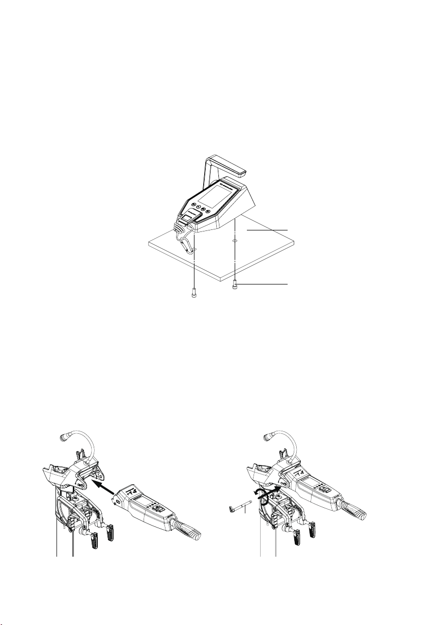
2.1 Montage der Evo Fernsteuerung
Beachten Sie die Einbauanleitung der Fernbedienung, um Löcher in die Schiffsplatine
zu bohren, und verwenden Sie die Schrauben, um die Fernsteuerungsbox wie in
Abbildung 2-1 gezeigt zu befestigen.
Rumpf
Schraube
Abbildung 2-1
2.2 Montage der Evo Pinne
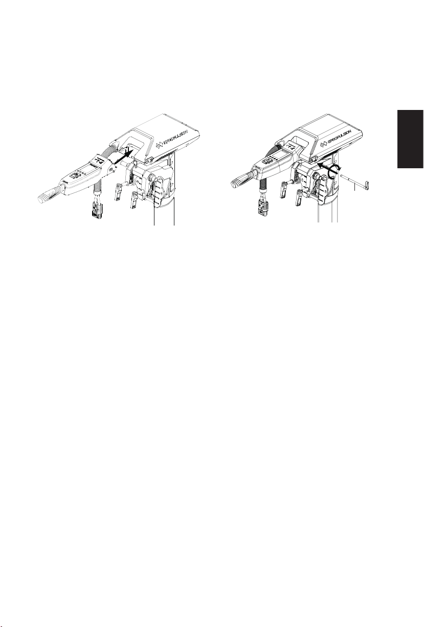
2.2.1 Montage am SPIRIT 1.0 Evo
1. Bringen Sie die Pinne an der Maschine an (Abbildung 2-2).
2. Schieben Sie den Handgriffwelle bis zum Anschlag in die Bohrung ein und
verriegeln Sie sie entgegen dem Uhrzeigersinn (Abbildung 2-3).
Pinnenachse
Abbildung 2-2 Abbildung 2-3
22
Page 25
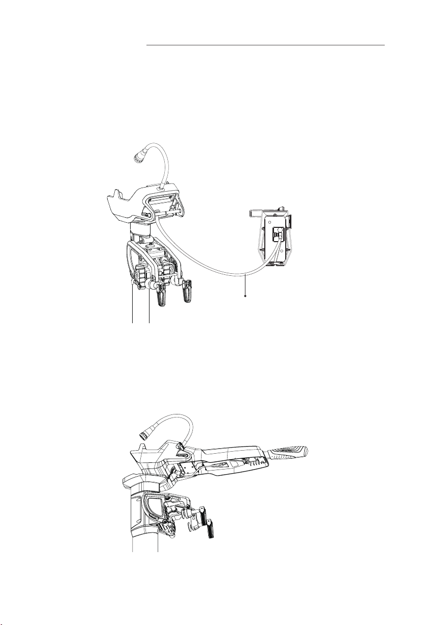
2.2.1 Montage am NAVY 3.0 Evo/NAVY 6.0 Evo
1. Bringen Sie die Pinne an der Maschine an (Abbildung 2-4).
2. Schieben Sie die Handgriffwelle bis zum Anschlag in die Bohrung ein und
verriegeln Sie sie im Uhrzeigersinn (Abbildung 2-5).
Pinnenachse
Abbildung 2-4 Abbildung 2-5
Deutsch
23
Page 26
3 Verkabelung
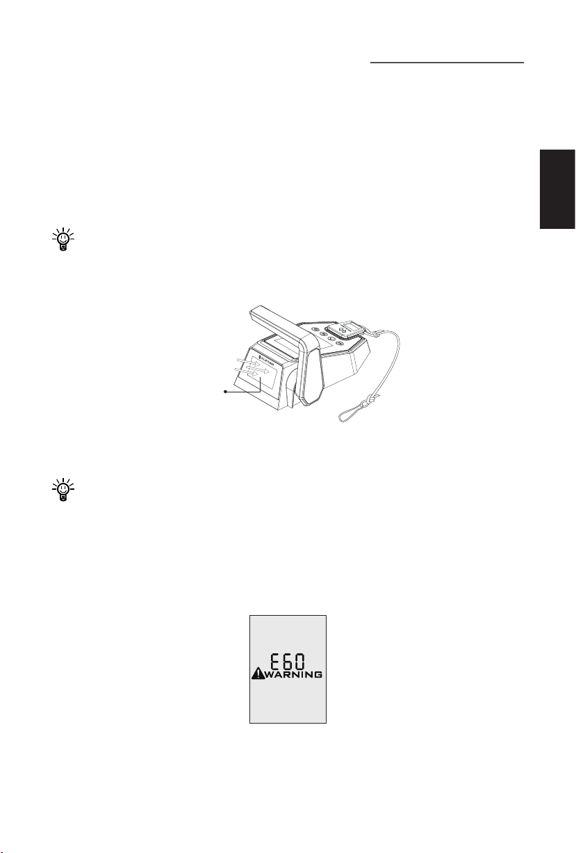
3.1 Verbinden der Fernsteuerung mit dem Außenborder
Falls die Fernsteuerung per Kabel mit der Maschine verbunden werden muss, wird ein
Verbindungskabel benötigt, um die Maschine und den Kommunikationsanschluss der
Fernsteuerung zu verbinden (Abbildung 3-1).
Verbindungskabel
Abbildung 3-1
3.2 Verbinden der Pinne mit dem Außenborder
Nach der Montage der Pinne müssen Sie den Kommunikationsanschluss der Pinne
mit dem Kommunikationsanschluss der Maschine verbinden (Abbildung 3-2).
Abbildung 3-2
24
Page 27
4 Auaden der Fernsteuerung
Die Fernsteuerung verfügt zur Stromversorgung über eine eingebaute Lithium-Batterie. Die Batterie wird bei normalem Gebrauch automatisch über Solarenergie oder
eine Kabelverbindung geladen.
4.1 Auaden mit Solarenergie
Bei ausreichend Sonnenschein erzeugt das Solarmodul genügend Strom, um die eingebaute Lithium-Batterie aufzuladen.
Richten Sie das Solarmodul der Fernsteuerung aufs Sonnenlicht aus, um einen
besseren Ladeeffekt zu erzielen.
Solarmodul
(zur Sonne hin
ausgerichtet)
Abbildung 4-1
Deutsch
Es wird das Auaden mit Solarenergie empfohlen.
4.2 Kabelgebundenes Auaden
Wenn die Fernsteuerung für längere Zeit nicht genügend Sonnenenergie erhält, entleert sich die Batterie. In diesem Fall wird der Fehlercode E60 (Abbildung 6-3) angezeigt, um Sie daran zu erinnern, die Batterie der Fernsteuerung zu laden.
Abbildung 4-2
25
Page 28
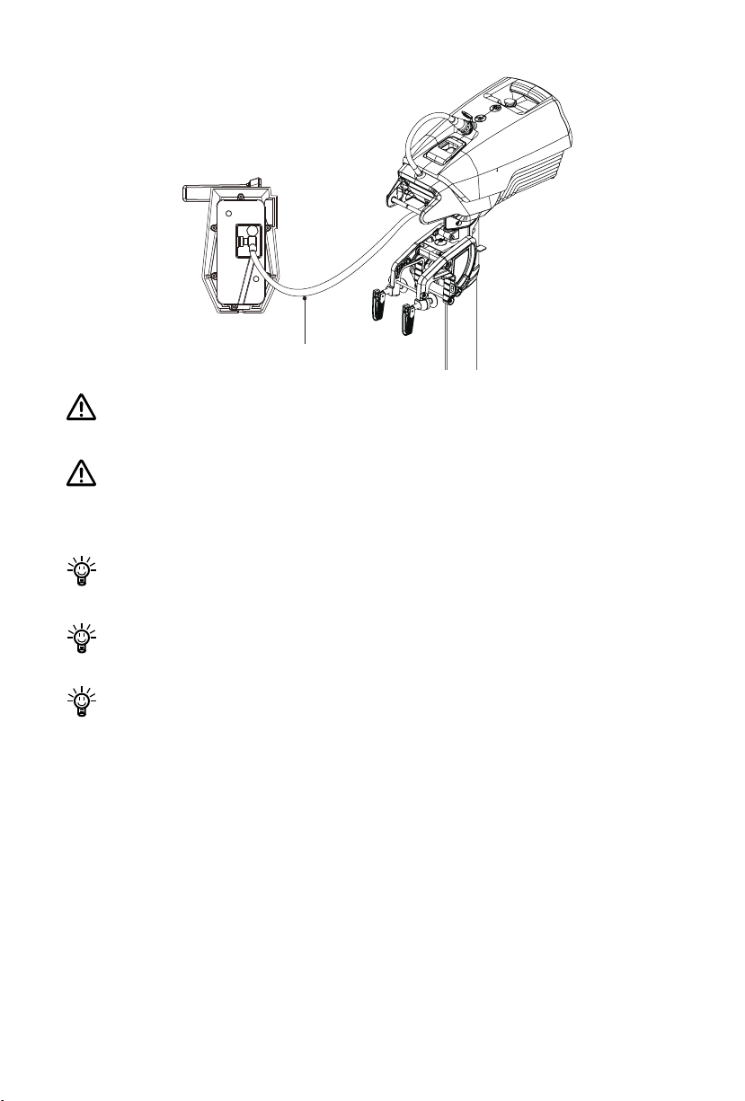
Abbildung 4-3
Verbindungskabel
Achten Sie bei längerer Lagerung darauf, das Steuerungssystem alle 6 Monate
zu laden, um eine Tiefenentladung zu vermeiden.
Schließen Sie den Hauptschalter nicht mit anderen Netzteilen kurz. Der
Hauptschalter sollte am Boot montiert sein, und die Rückplatte des
Hauptschalters sollte nicht entfernt werden.
Laden Sie das Steuerungssystem nach längerer Lagerung vor der Verwendung
auf.
Das Verbindungskabel ist nicht im Lieferumfang enthalten. Bitte kaufen Sie
eines bei Ihrem Händler, wenn Sie sich für diese Lademethode entscheiden.
Sobald das Verbindungskabel gelöst wird, bricht der Ladevorgang automatisch
ab und der laufende Motor wird stoppt. Bitte starten Sie den Motor neu.
26
Page 29
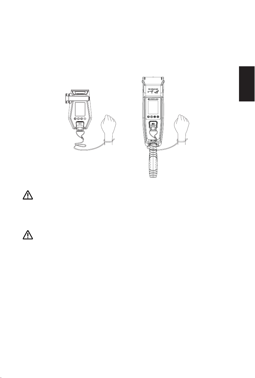
5 Reißleinenschalter einsetzen
Die Reißleine um Ihr Handgelenk legen oder an Ihrer Schwimmweste befestigen.
Im Notfall kann der Motor durch Entfernen des Reißleinenschalters gestoppt werden.
Vor dem erneuten Start des Motors muss der Reißleinenschalter wieder auf die
vorgesehene Position angebracht werden.
Abbildung 5-1
Der Reißleinenschalter erzeugt ein Magnetfeld. Zwischen Personen mit
Herzschrittmachern oder implantierten Defibrillatoren, magnetischen Karten
bzw. anderen magnetischen Gegenständen und dem Schalter muss ein
Sicherheitsabstand von mindestens 50 cm eingehalten werden.
Deutsch
Das Magnetfeld des Reißleinenschalters beeinflusst elektrische Messgeräte und
muss daher von ihnen ferngehalten werden.
27
Page 30
6 Garantiebedingungen
Die Fa. ePropulsion übernimmt Garantie für alle durch autorisierte Händler erworbenen ePropulsion Produkte. Der Garantieumfang beinhaltet kostenlosen Umtausch
von Produkten, die schwerwiegende Qualitätsmängel aufweisen, Vertragsbedingungen nicht erfüllen bzw. kostenlosen Reparatur- oder Umtauschservice von fehlerhaften oder fehlenden Bauteilen. Die Festlegung der Garantiebedingungen dient zum
Schutz der Verbraucherrechte.
6.1 Garantiefrist
Produkt/Bauteil Frist
Evo-Fernsteuerung /
Evo-Pinne
Reparierte oder umge-
tauschte
Bauteile
Damit die Garantiebedingungen erfüllt werden, muss der Benutzer die der
Verpackung beiliegende Garantiekarte ausfüllen.
Das Typenschild des Produkts darf nicht beschädigt werden. Die Seriennummer
muss dem Typenschild entnommen werden. Das Typenschild darf auf keinen
Fall vom Produkt entfernt werden. Für Produkte ohne das Original-Typenschild
erlischt der Garantieanspruch gegenüber der Fa. ePropulsion.
2 Jahre ab dem Kaufdatum (nur bei nichtgewerblicher Nut-
zung)
Drei Monate ab dem Datum der Reparatur oder des Um-
tauschs.
Anmerkung:
1. Wenn diese drei Monate die Original-Garantiefrist nicht
überschreiten, dann bleibt die Garantie für diese reparierten
bzw. umgetauschten Bauteile für 2 Jahre (ab dem Kaufda-
tum des Produkts) gültig.
2. Wenn diese drei Monate die Original-Garantiefrist über-
schreiten, dann bleibt die Garantie für diese reparierten bzw.
umgetauschten Bauteile für 3 Monate (ab dem Serviceda-
tum der Reparatur oder des Umtauschs) gültig.
Die Garantie kann nur gewährleistet werden, wenn die vom Benutzer gemachten
Angaben richtig und vollständig sind.
28
Page 31
Der Benutzer muss die gültige Seriennummer seines Produkts, die ausgefüllte
Garantiekarte sowie den von einem autorisierten Vertragshändler ausgestellten
Kaufbeleg einreichen.
Das gültige Kaufdatum wird durch den Original-Kaufbeleg des ersten Käufers
bestimmt.
Die Garantiekarte darf nicht weitergegeben werden und wird bei Verlust nicht
ersetzt.
6.2 Von der Garantie ausgenommen
Das Produkt muss beim Einschicken zur Reparatur ausreichend verpackt sein. Es
wird empfohlen, die Original-Verpackung von ePropulsion zu verwenden. Wenn Bauteile durch unzureichende Verpackung beim Einschicken beschädigt werden, unterliegen diese Bauteile nicht den vereinbarten Garantieleistungen.
Darüber hinaus werden durch folgende Situationen verursachte Störungen oder
Schäden nicht als Garantiefall anerkannt, auch wenn die Garantiefrist noch nicht abgelaufen ist.
Bedienung, die mit dieser Bedienungsanleitung nicht konform ist.
Unfälle, unsachgemäße Handhabung, absichtliche Fehlnutzung, physikalische
Beschädigung, Überladung, Wassereintritt oder eigenmächtige Reparaturen.
Deutsch
Herunterfallen, unsachgemäße Instandhaltung oder Lagerung.
Für normalen Verschleiß, der die Funktionen des Produkts nicht beeinusst, ist
ebenfalls keine Garantieleistung möglich.
Für Verschleißteile wird keine Garantie geleistet.
Für Sachschäden oder sonstige Ansprüche auf Schadensersatz, die durch den
Einsatz der Produkte entstanden sind, übernehmen wir keine Verantwortung.
Der Garantieanspruch wird nicht gewährt, wenn eine der folgenden Situationen
zutrifft: Das ePropulsion Produkt wurde nicht bei einem Vertragshändler der Fa.
ePropulsion erworben. Das ePropulsion Produkt wurde gewerblich eingesetzt.
Die eingereichten Unterlagen beim Garantiefall sind unvollständig.
29
Page 32

6.3 Abwicklung eines Garantiefalls
Bei der Feststellung von Qualitätsmängeln können Sie gemäß dem folgenden Verfahren Ihren Garantieanspruch bei einem Vertragshändler geltend machen:
1. Die Garantiekarte richtig und vollständig ausfüllen. Die Karte zusammen mit ei-
nem gültigen Kaufbeleg bei einem autorisierten ePropulsion Vertragshändler einreichen. Für einen Garantiefall sind folgende Unterlagen notwendig: die Garantiekarte, die Seriennummer des Produkts und der Kaufbeleg.
2. Nach der Bestätigung des Garantieanspruchs geben Sie das fehlerhafte Produkt
bei einer autorisierten Servicestelle ab. Achten Sie darauf, dass das Typenschild
unbeschädigt ist.
3. Der Vertragshändler der Fa. ePropulsion kümmert sich um die Fehlerdiagnose
und die Reparatur des defekten Bauteils oder veranlasst einen Umtausch.
4. Bei einem Garantiefall müssen Sie keine Kosten für die Reparatur oder den Um-
tausch übernehmen. Sämtliche Versandkosten während der Abwicklung muss
jedoch der Benutzer selbst tragen.
5. Nach sorgfältigen Prüfungen führen die Vertragshändler der Fa. ePropulsion Re-
paraturen oder Umtausch der fehlerhaften oder defekten Bauteile durch.
6. Bei einer Ablehnung des Garantieanspruchs erhalten Sie von Ihrem ePropulsion
Vertragshändler für die fälligen Reparaturarbeiten einen Kostenvoranschlag, in
dem auch die gesamten Versandkosten enthalten sind. Der Vertragshändler führt
die Reparatur erst nach dem Erhalt Ihrer Bestätigung durch.
Nach dem Ablauf der Garantiefrist gewährleisten wir unseren Kunden,
ihre Reparaturen zu einem günstigen Preis von Vertragshändlern der Fa.
ePropulsion durchführen zu lassen.
30
Page 33

Page 34

Page 35

Page 36
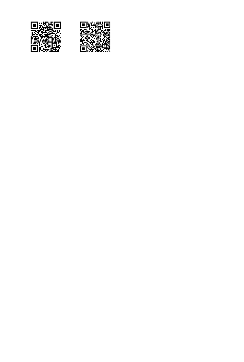
Scan to register
your product
Vielen Dank, dass Sie sich Zeit genommen haben, die
Bedienungsanleitung zu Ihrem ePropulsion Produkt
durchzulesen.
Bei Fragen oder Problemen zu dem Handbuch stehen wir
Ihnen sehr gern zur Verfügung.
Nehmen Sie bitte mit uns Kontakt auf.
Thanks for reading this user manual.
If you have any concerns or find any problems while reading,
please don't hesitate to contact us. We are delighted to offer
service for you.
Product
tutorial
Guangdong ePropulsion Technology Limited
Website: www.epropulsion.com
Email: [email protected]
 Loading...