

Page 1

OpenCPI
Matchstiq-Z1 Getting Started Guide
Version 1.5
1
Page 2

Matchstiq-Z1 Getting Started Guide ANGRYVIPER Team
Revision History
Revision Description of Change Date
v1.1 Initial Release 3/2017
v1.2 Updated for OpenCPI Release 1.2 8/2017
v1.3 Updated for OpenCPI Release 1.3 2/2018
v1.4 Update descriptions and paths 9/2018
v1.5 Update for OpenCPI Release 1.5 4/2019
2
Page 3

Matchstiq-Z1 Getting Started Guide ANGRYVIPER Team
Table of Contents
1 References 4
2 Overview 5
3 Prerequisites 5
3.1 Installation of provided OpenCPI projects: core and assets . . . . . . . . . . . . . . . . . . . . . . . . 5
3.2 Vendor Software Setup . . . . . . . . . . . . . . . . . . . . . . . . . . . . . . . . . . . . . . . . . . . . . 6
3.3 Building OpenCPI projects: core and assets . . . . . . . . . . . . . . . . . . . . . . . . . . . . . . . . 6
3.4 Hardware Setup . . . . . . . . . . . . . . . . . . . . . . . . . . . . . . . . . . . . . . . . . . . . . . . . . 6
4 SD Card Setup 8
4.1 Make a backup image of factory SD card (assumes Linux host) . . . . . . . . . . . . . . . . . . . . . . 8
4.2 Format the SD card for OpenCPI . . . . . . . . . . . . . . . . . . . . . . . . . . . . . . . . . . . . . . . 8
4.3 Copy embedded OS files to SD card, “ATLAS” partition . . . . . . . . . . . . . . . . . . . . . . . . . . 8
4.4 Copy files to SD card for desired Mode(s) . . . . . . . . . . . . . . . . . . . . . . . . . . . . . . . . . . 9
4.4.1 Standalone and Network Modes . . . . . . . . . . . . . . . . . . . . . . . . . . . . . . . . . . . . 9
4.4.2 Standalone Mode . . . . . . . . . . . . . . . . . . . . . . . . . . . . . . . . . . . . . . . . . . . . 9
4.4.3 Network Mode . . . . . . . . . . . . . . . . . . . . . . . . . . . . . . . . . . . . . . . . . . . . . 9
4.5 SD Card Source . . . . . . . . . . . . . . . . . . . . . . . . . . . . . . . . . . . . . . . . . . . . . . . . . 9
4.6 No changes required for “SDHOME” partition . . . . . . . . . . . . . . . . . . . . . . . . . . . . . . . . 9
5 Script Setup 10
5.1 Setting up the Network and Standalone Mode scripts . . . . . . . . . . . . . . . . . . . . . . . . . . . . 10
5.1.1 Network Mode . . . . . . . . . . . . . . . . . . . . . . . . . . . . . . . . . . . . . . . . . . . . . 10
5.1.2 Standalone Mode . . . . . . . . . . . . . . . . . . . . . . . . . . . . . . . . . . . . . . . . . . . . 10
5.2 Setup system time reference . . . . . . . . . . . . . . . . . . . . . . . . . . . . . . . . . . . . . . . . . . 11
5.3 “rsync” provided binary . . . . . . . . . . . . . . . . . . . . . . . . . . . . . . . . . . . . . . . . . . . . 11
6 Hardware Setup 12
6.1 Establish a Serial Connection . . . . . . . . . . . . . . . . . . . . . . . . . . . . . . . . . . . . . . . . . 12
6.2 Update U-boot Variables . . . . . . . . . . . . . . . . . . . . . . . . . . . . . . . . . . . . . . . . . . . 12
7 Development Host Setup - Network Mode ONLY 14
7.1 Network Mounting Mode . . . . . . . . . . . . . . . . . . . . . . . . . . . . . . . . . . . . . . . . . . . 14
7.1.1 CentOS 6 . . . . . . . . . . . . . . . . . . . . . . . . . . . . . . . . . . . . . . . . . . . . . . . . 14
7.1.2 CentOS 7 . . . . . . . . . . . . . . . . . . . . . . . . . . . . . . . . . . . . . . . . . . . . . . . . 14
8 Configuring the run-time environment on the platform 16
8.1 Network Mode . . . . . . . . . . . . . . . . . . . . . . . . . . . . . . . . . . . . . . . . . . . . . . . . . 16
8.2 Standalone Mode . . . . . . . . . . . . . . . . . . . . . . . . . . . . . . . . . . . . . . . . . . . . . . . . 18
9 Build an Application 20
10 Run an Application 20
10.1 Network Mode . . . . . . . . . . . . . . . . . . . . . . . . . . . . . . . . . . . . . . . . . . . . . . . . . 20
10.2 Standalone Mode . . . . . . . . . . . . . . . . . . . . . . . . . . . . . . . . . . . . . . . . . . . . . . . . 23
Appendices 25
A Intermittent Errors 25
B Using ISE instead of Vivado with the Matchstiq-Z1 25
C Driver Notes 25
3
Page 4

Matchstiq-Z1 Getting Started Guide ANGRYVIPER Team
1 References
This document assumes a basic understanding of the Linux command line (or “shell”) environment. The reference(s)
in Table 1 can be used as an overview of OpenCPI and may prove useful.
Title Link
Acronyms and Definitions Acronyms_and_Definitions.pdf
Getting Started Getting_Started.pdf
Installation Guide RPM_Installation_Guide.pdf
Table 1: References
4
Page 5

Matchstiq-Z1 Getting Started Guide ANGRYVIPER Team
2 Overview
This document provides steps for configuring a factory provided Epiq Solutions Matchstiq-Z1 SDR with the OpenCPI
run-time environment for executing applications, configuring a development system to build OpenCPI bitstreams
targeting the matchstiq_z1 platform, and examples of executing applications on the OpenCPI configured MatchstiqZ1. Note: Only the Z1 version of the Epiq Solutions Matchstiq product line is supported by OpenCPI.
3 Prerequisites
This guide assumes that, at a minimum, the following RPMs are installed:
RPM Name Description
All prerequisite RPMs These packages have OpenCPI-specific patches
and are provided as RPMs. This packaging ensures they will not conflict with other installed
copies by using a nonstandard installation location of /opt/opencpi/prerequisites.
angryviper-ide-*.x86 64.rpm The ANGRYVIPER IDE (Eclipse with plugins).
See RPM Installation Guide.pdf, Appendix D for
an alternative method to set up the IDE using an
existing Eclipse installation.
opencpi-*.x86_64.rpm Base installation RPM includes the runtime por-
tion of the Component Development Kit (CDK)
and the source for the ocpi.core and ocpi.assets
Projects containing framework essential components, workers, platforms, etc.
opencpi-devel-*.x86_64.rpm Additional header files and scripts for developing
new assets as HDL and/or RCC.
opencpi-sw-platform-xilinx13_3-*.noarch.rpm Additional files necessary to build the framework
targeting specific RCC/software platforms, independent of the final deployed hardware.
opencpi-hw-platform-matchstiq_z1-xilinx13_3-*.noarch.rpm Additional files necessary to build the frame-
work targeting specific hard-ware platform “X”
when running RCC platform “Y” (“Y” can be “no
sw”). This RPM also includes hardware-specific
SD Card images when applicable.
3.1 Installation of provided OpenCPI projects: core and assets
This guide assumes the user has executed ocpi-copy-projects, accepting the default settings, to copy and register the
core and assets projects from the /opt/opencpi/projects for building bitstreams for the Matchstiq-Z1. Reference
the Getting Started Guide for details on ocpi-copy-projects. While registering of the projects is performed during
the execution of ocpi-copy-projects, changes to the registry can be made via ocpidev un/register project or the
ANGRYVIPER GUI.
$ ocpi-copy-projects
...
$ ls ~/ocpi_projects
assets core
$ ocpidev show registry
Project registry is located at: /opt/opencpi/cdk/../project-registry
---------------------------------------------------------------------------------------| Project Package-ID | Path to Project | Valid/Exists |
| ------------------ | --------------- | ------------ |
| ocpi.core | /home/user/ocpi_projects/core | True |
5
Page 6

Matchstiq-Z1 Getting Started Guide ANGRYVIPER Team
| ocpi.assets | /home/user/ocpi_projects/assets | True |
----------------------------------------------------------------------------------------
3.2 Vendor Software Setup
The platform that is expected to be used is the Epiq Solutions Matchstiq-Z1 (e.g. matchstiq_z1). This
OpenCPI-enabled platform provides the capability of deploying hardware and software workers while using Xilinx’s
13.3 distribution of Linux.
The synthesizers and cross-compilers required to build HDL and RCC Workers for this platform are installed by
following the instructions found in the OpenCPI FPGA Vendor Tools Installation Guide. This document assumes
that the user has installed the appropriate versions of Vivado and the Xilinx SDK.
3.3 Building OpenCPI projects: core and assets
The core and assets projects must be built in a specific order for this platform. This section outlines how to build
the relevant projects and provides the commands to do so.
For this document, the projects should be built as follows:
1. Build core for the xilinx13_3 RCC Platform and the matchstiq_z1 HDL Platform (approx 30 min)
2. Build assets for the xilinx13_3 RCC Platform and the matchstiq_z1 HDL Platform, but omit assemblies
(approx 45 min)
3. Build the testbias assembly from the assets project. This will be used later in this guide. (approx 10 min)
$ cd /home/<user>/ocpi_projects/
$ ocpidev build -d core --rcc-platform xilinx13_3 --hdl-platform matchstiq_z1
$ ocpidev build -d assets --rcc-platform xilinx13_3 --hdl-platform matchstiq_z1 --no-assemblies
$ ocpidev build -d assets hdl assembly testbias --hdl-platform matchstiq_z1
Note: replace “<user>” with your username in the commands above.
Each of these build commands can also be performed via the ANGRYVIPER IDE as follows:
To perform this operation within the IDE:
1. Open the ANGRYVIPER Perspective
2. Select the asset from OpenCPI Pro ject View
3. Import to ANGRYVIPER Operations Panel using “ >” button
4. Select the RCC and/or HDL platforms for the build (use
5. Click “Build”
See the ANGRYVIPER Team’s Getting Started Guide for additional information concerning the use of ocpidev
and the ANGRYVIPER IDE to build OpenCPI assets.
Ctrl for multiple selection)
3.4 Hardware Setup
• Epiq Solutions Matchstiq-Z1 SDR Kit
It is expected that this SDR kit includes a power supply, two SMA/SMB adapters, micro-USB to USB cable,
micro-SD card installed internally (expected).
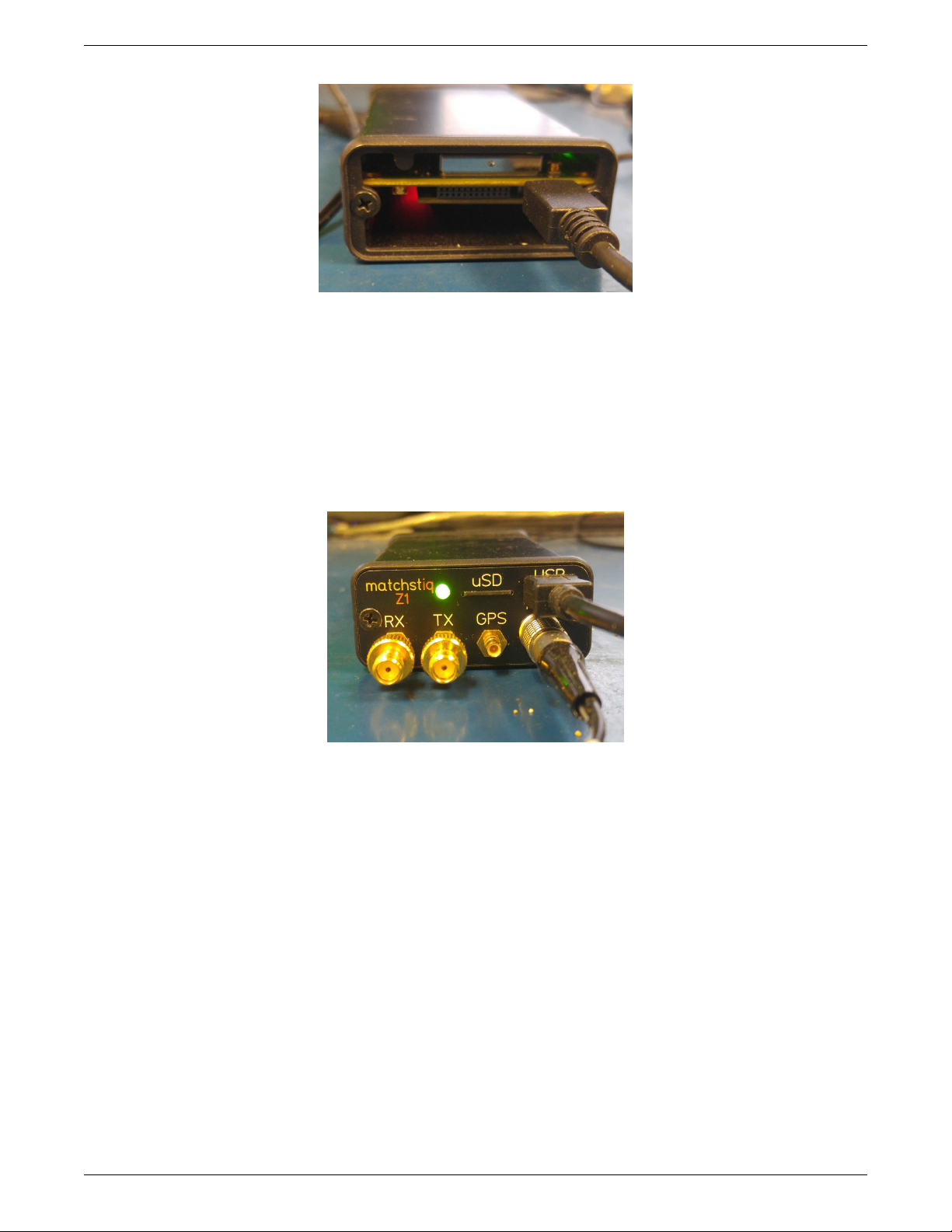
A micro-USB connector on the back of the Matchstiq-Z1 provides access to the serial connection. To expose
this micro-USB connector, the two screws in the back plate must be removed. Historically, this connector’s
attachment to the PCB has been extremely fragile, so be careful when inserting/removing the mating
cable.
6
Page 7
Matchstiq-Z1 Getting Started Guide ANGRYVIPER Team
Figure 1: Connected Back Panel
• Micro-USB to Ethernet adapter. To allow network access when plugged into the front panel micro-USB
port. The OpenCPI BSP for the Matchstiq-Z1 is configured for DHCP. An Ethernet connection is required
for developing OpenCPI in Network mode.
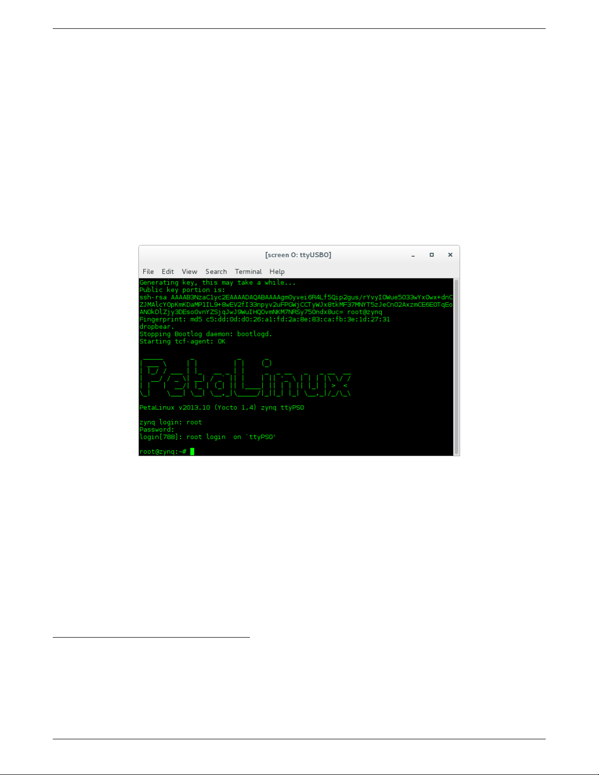
On the front panel of the Matchstiq-Z1, there are three labeled SMB (50 Ohm) connectors: “RX” (receive),
“TX” (transmit), and “GPS”. From the factory, the Matchstiq-Z1 is provided with two SMB to SMA adapters.
Due to the RF performance to the transceiver device, any RF COAX cables should be rated up to at least
3GHz.
Figure 2: Connected Front Panel
• Access to a network which supports DHCP. (Network Mode)
• Micro-SD card, 4GB+ (OPTIONAL, as it is possible to use internally installed card)
• Micro-SD card reader
7
Page 8

Matchstiq-Z1 Getting Started Guide ANGRYVIPER Team
4 SD Card Setup
The Matchstiq-Z1 SDR is equipped with two SD card slots: one internal and one accessible via the front panel. It is
expected that the SDRs are shipped from Epiq Solutions with an SD card installed in the internal slot that is loaded
with their embedded environment. A feature of this SDR is that when an SD card is installed in the front panel SD
slot, the SDR will automatically choose to operate from this SD card rather than the internal SD card. Therefore,
a user can easily switch the SDR between operating in the Epiq Solutions or OpenCPI environment.
The Matchstiq-Z1’s factory SD card has a non-default formatting and content, which must be maintained for
proper operation. This guide assumes that the internal (factory) SD card is being use for OpenCPI and will be
reinstalled in the front panel SD card slot. If the user desires the use of a new SD card, the user must ensure that
it is initially imaged from the factory provided SD card, as there is a unique partition containing required content
from the OEM.
4.1 Make a backup image of factory SD card (assumes Linux host)
This section provides the steps for creating an SD card backup image. Access the internal SD card slot by removing
the screws from the front and back plates, then slide the board assembly out of the enclosure. Flip the SD card slot
open and lift the card out. Insert the SD card into a USB reader and install into a host machine.
1. Determine the device file name for the SD card by executing dmesg command below. It will likely be something
like /dev/sdb or /dev/mmcblk0.
$ dmesg | tail -n 15
2. Run the following dd command to make a backup image, where DEVICENAME was determined above. This
step should take ∼ 15 minutes depending on the card size.
$ dd if=DEVICENAME of=backup.image
4.2 Format the SD card for OpenCPI
The Matchstiq-Z1 SDR requires an SD card with a specific partition and content. The recommend method for
formatting a new SD card is to begin by imaging the new card using the backup image of the factory SD card,
removing factory default files and directory and copying OpenCPI content to SD card.
1. Format an SD card for OpenCPI, (restore to its original factory default captured in the previous section), run
the command
$ dd of=DEVICENAME if=backup.image
2. To prepare for OpenCPI provided content to be placed onto the SD card, remove all factory files and directories
from the ATLAS partition.
4.3 Copy embedded OS files to SD card, “ATLAS” partition
WARNING: The user must ensure that the contents of the SD, match the version of the OpenCPI release that the
artifacts were built against.
Copy the following files/directories into the “ATLAS” partition:
$ cp /opt/opencpi/cdk/matchstiq_z1/sdcard-xilinx13_3/iveia-atlas-i-z7e.dtb /run/media/<user>/ATLAS/
$ cp /opt/opencpi/cdk/matchstiq_z1/sdcard-xilinx13_3/u-boot.bin /run/media/<user>/ATLAS/
$ cp /opt/opencpi/cdk/matchstiq_z1/sdcard-xilinx13_3/uImage /run/media/<user>/ATLAS/
$ cp /opt/opencpi/cdk/matchstiq_z1/sdcard-xilinx13_3/uramdisk.image.gz /run/media/<user>/ATLAS/
Any files/directories copied to the “ATLAS” partition will appear at /mnt/card on the Matchstiq-Z1.
The need to copy the /opt/opencpi/cdk/matchstiq_z1/opencpi onto the SD card is dependent on the desired
operating mode (Standalone vs Network) and is discussed in the following sections.
8
Page 9

Matchstiq-Z1 Getting Started Guide ANGRYVIPER Team
4.4 Copy files to SD card for desired Mode(s)
As previously discussed, Standalone and Network modes offer trade-offs for configuring the run-time environment
of the platform. The following sections provide instructions for copying specific files/directories to the SD card in
support of these modes. For maximum flexibility and completion of this getting started guide, it is recommended
that the SD card be configured to support both modes, as covered in the next sub-section. However, instructions for
configuring the SD card for each mode separately, have also been provided.
4.4.1 Standalone and Network Modes
The SD can be setup to support both modes, as there is no conflict between the files/directories for either mode. To
setup the SD to support both modes:
After performing the steps from 4.3, copy the entire opencpi directory to the SD card.
$ cp -rL /opt/opencpi/cdk/matchstiq_z1/sdcard-xilinx13_3/opencpi /run/media/<user>/ATLAS/
$ cp /home/<user>/ocpi_projects/assets/hdl/assemblies/testbias/container-testbias_matchstiq_z1_base/\
target-zynq/testbias_matchstiq_z1_base.bit.gz /run/media/<user>/ATLAS/opencpi/xilinx13_3/artifacts/
4.4.2 Standalone Mode
After performing the steps from 4.3, copy the entire opencpi directory to the SD card, then copy the relevant
bitstreams, artifacts into the artifacts directory and application XMLs into the applications directory. For this
getting started guide, only one bitstream is required to be copied onto the SD cards, where as the required artifacts
and application XML where copied to the SD along with the entire opencpi directory.
$ cp -rL /opt/opencpi/cdk/matchstiq_z1/sdcard-xilinx13_3/opencpi /run/media/<user>/ATLAS/
$ cp /home/<user>/ocpi_projects/assets/hdl/assemblies/testbias/container-testbias_matchstiq_z1_base/\
target-zynq/testbias_matchstiq_z1_base.bit.gz /run/media/<user>/ATLAS/opencpi/xilinx13_3/artifacts/
4.4.3 Network Mode
After performing the steps from 4.3, create a directory on the partition named “opencpi” and copy the following files
into the this directory:
$ mkdir /run/media/<user>/ATLAS/opencpi
$ cp /opt/opencpi/cdk/matchstiq_z1/sdcard-xilinx13_3/opencpi/system.xml \
/run/media/<user>/ATLAS/opencpi/
$ cp /opt/opencpi/cdk/matchstiq_z1/sdcard-xilinx13_3/opencpi/default_mynetsetup.sh \
/run/media/<user>/ATLAS/opencpi/
$ cp /opt/opencpi/cdk/matchstiq_z1/sdcard-xilinx13_3/opencpi/zynq_net_setup.sh \
/run/media/<user>/ATLAS/opencpi/
4.5 SD Card Source
The final SD Card artifacts are distributed in /opt/opencpi/cdk/matchstiq_z1/ via RPM as noted previously.
The end user is not required nor expected to generate the files.
4.6 No changes required for “SDHOME” partition
All the files in this partition can be ignored. If space for files is required for your application, they can be deleted.
9
Page 10

Matchstiq-Z1 Getting Started Guide ANGRYVIPER Team
5 Script Setup
There are two type of setups or modes for running applications on any embedded radio: Network and Standalone. In
Network mode, a development system hosts the OpenCPI tree as an NFS server to the Matchstiq-Z1 which is an NFS
client. This configuration provides quick and dynamic access to all of OpenCPI, and presumably any applications,
components and bitstreams. In Standalone mo de, all the artifacts are located on the SDR’s local storage (e.g. SD
card) and no network connection is required. This may be more suited for deployment scenarios in which network
connection is not possible or practical. Network mode is generally preferred during the development process.
5.1 Setting up the Network and Standalone Mode scripts
For each mode, a startup script is used to configure the environment of the embedded system. The OpenCPI
framework provides a default script for each mode. The default scripts are to be copied and modified per the user’s
requirements.
5.1.1 Network Mode
1) Make a copy of the default script for editing.
$ cp /run/media/<user>/ATLAS/opencpi/default_mynetsetup.sh \
/run/media/<user>/ATLAS/opencpi/mynetsetup.sh
2) Edit the copy
1. In mynetsetup.sh, uncomment the following lines which are necessary for mounting core and assets project:
mkdir -p /mnt/ocpi_core
mount -t nfs -o udp,nolock,soft,intr $1:/home/user/ocpi_projects/core /mnt/ocpi_core
mkdir -p /mnt/ocpi_assets
mount -t nfs -o udp,nolock,soft,intr $1:/home/user/ocpi_projects/assets /mnt/ocpi_assets
2. Edit /home/user/ocpi_projects/core and /home/user/ocpi_projects/assets to reflect the paths to the
core and assets project on the host, e.g.:
mkdir -p /mnt/ocpi_core
mount -t nfs -o udp,nolock,soft,intr $1:/home/johndoe/ocpi_projects/core /mnt/ocpi_core
mkdir -p /mnt/ocpi_assets
mount -t nfs -o udp,nolock,soft,intr $1:/home/johndoe/ocpi_projects/assets /mnt/ocpi_assets
5.1.2 Standalone Mode
In this mode, all OpenCPI artifacts that are required to run any application on the Matchstiq-Z1 must be copied
onto the SD card. Building the provided projects to obtain such artifacts is discussed in Section 3.3. Once the
artifacts have been created, they must be copied to the SD card in Section 4. In general, any required .so (RCC
workers), .bit.gz (hdl assemblies), and application XMLs or executables must be copied to the ATLAS partition
of the SD card.
1) Make a copy of the default script for editing
$ cp /run/media/<user>/ATLAS/opencpi/default_mynetsetup.sh \
/run/media/<user>/ATLAS/opencpi/mynetsetup.sh
2) Edit the copy
Unlike Network mode, there is no required modifications to this script.
3) Copy any additional artifacts to SD card’s opencpi/xilinx13_3/artifacts/ directory
10
Page 11

Matchstiq-Z1 Getting Started Guide ANGRYVIPER Team
5.2 Setup system time reference
If Linux system time is not required to be accurate, this step may be skipped.
For either Network or Standalone mode, the following settings that are passed by my[net]setup.sh to the
zynq_[net_]setup.sh scripts may require modification:
• Identify the system that is to be used as a time server, where the default is “time.nist.gov” and is set in
/mnt/card/opencpi/ntp.conf. A valid time server must support NTP.
• Identify the current timezone description, where the default is “EST5EDT,M3.2.0,M11.1.0”. Change this if
required for the local timezone. See man tzset on the host PC for more information.
• If a time server is not required, or cannot connect to a time server, the user is required to manually set the
time at radio start-up. Use the date command to manually set the Linux system time. See man date on the
host PC for more information.
5.3 “rsync” provided binary
An ARM-compiled version of “rsync” is provided in the included SD card image for xilinx13_3. This tool allows
the use of standalone mode while shortening the required developer time to synchronize the artifacts being
developed. For command-line usage, see the rsync home page. The easiest usage is to have the radio “pull” from the
developer’s workstation; this does not need any additional command-line arguments.
Implementation Details
Unfortunately, the “rsync” executable is not in the default path because when called remotely, it requests a
non-interactive shell. For this reason, a “pull” approach is recommended. If a user for some reason req uires a “push”
from the workstation to the radio, the local “rsync” executable must be told the remote location of the rsync
executable to call, e.g. rsync –rsync-path=/mnt/card/opencpi/xilinx13_3/bin/rsync
11
Page 12

Matchstiq-Z1 Getting Started Guide ANGRYVIPER Team
6 Hardware Setup
6.1 Establish a Serial Connection
By default, the USB to Serial adapter connects as read-only, which requires sudo privileges for establishing a serial
connection. OpenCPI recognizes that sudo may not be available and has provided an alternative for configuring
the device thereby allowing all users access to the device. Specifically, this is accomplished by adding udev rules to
instruct the device connection to have read and write permissions for all users.
• If OpenCPI was installed via RPMs, the udev rules are automatically setup for the user.
• If OpenCPI was installed from source, then the user must manually add the udev rules by copying the file from
the host machine’s installation directory to the host machine’s /etc/udev/rules.d/. The following command
can be used as a guide:
$ cd /etc/udev/rules.d/
$ sudo ln -s /<install-path>/opencpi/cdk/matchstiq_z1/host-udev-rules/97-matchstiq_z1.rules \
97-matchstiq_z1.rules
• Whether installed via RPMs or source (and manually creating the symbolic link), the USB to Serial adapter
will be connected as /dev/matchstiq_z1_0 with read and write permissions for all users.
Once the Matchstiq-Z1 is powered on, use the following command to connect to the serial port:
$ screen /dev/matchstiq_z1_0 115200
6.2 Update U-boot Variables
1. Remove power from the Matchstiq-Z1 unit.
2. Insert the SD card into the front panel SD card slot.
3. Connect a terminal to the rear micro-USB connector of the Matchstiq-Z1 with a baud rate of 115200.
• per the previous section, “screen /dev/matchstiq_z1_0 115200” can be used to connect to the serial
port.
4. Apply power to the Matchstiq-Z1 with the terminal still connected and stop the boot process by hitting any
key to enter the U-Boot terminal.
5. Run the following commands to setup the environment variables:
• setenv bootcmd 'ivmmc; run ocpiboot'
• setenv ocpiboot 'setenv bootargs console=ttyPS0,115200n8 root=/dev/ram rw earlyprintk;
setenv fdt_high ffffffff; setenv initrd_high 0x1000000; fatload mmc ${iv_mmc} ${dtbaddr}
${dtbfile}; fatload mmc ${iv_mmc} ${loadaddr} ${bootfile}; fatload mmc ${iv_mmc}
0x2000000 uramdisk.image.gz; bootm ${loadaddr} 0x2000000 ${dtbaddr}'
*Note: This should b e a one-line command. Make sure there are no newlines.
• saveenv
6. These U-Boot environment variables are now saved to the second partition of the SD card
Verify that the changes are correct by running the command “env p” and comparing to:
baudrate=115200
bootcmd=ivmmc;run ocpiboot
bootdelay=3
bootfile=uImage
defargs=setenv bootargs console=ttyPS0,115200n8 mem=240M iv_mb=${iv_mb} iv_io=${iv_io}
iv_bp=${iv_bp} iv_mmc=${iv_mmc} ${otherargs}
dtbaddr=0x02a00000
12
Page 13

Matchstiq-Z1 Getting Started Guide ANGRYVIPER Team
dtbfile=iveia-atlas-i-z7e.dtb
iv_io=205-00034-00-A0,,Atlas-II_GF_Carrier
iv_io_default=205-00034-00-A0,,Atlas-II_GF_Carrier
iv_io_ord=00034
iv_mb=205-00049-00-B1,A2WT9,Atlas-I-Z7e
iv_mb_ord=00049
iv_mmc=0
loadaddr=0x03000000
mmcdtload=fatload mmc ${iv_mmc} ${dtbaddr} ${dtbfile};fdt addr ${dtbaddr};fdt set
/chosen bootargs "${bootargs}";fdt ivclean ${iv_mb_ord}
mmcxload=axi_reset 1; fatload mmc ${iv_mmc} ${loadaddr} ${xloadfile};xload ${loadaddr}
${filesize}; axi_reset 0;
ocpiboot=setenv bootargs console=ttyPS0,115200n8 mem=240M root=/dev/ram rw earlyprintk;
setenv fdt_high ffffffff; setenv initrd_high 0x1000000; fatload mmc ${iv_mmc} ${dtbaddr}
${dtbfile}; fatload mmc ${iv_mmc} ${loadaddr} ${bootfile}; fatload mmc ${iv_mmc} 0x2000000
uramdisk.image.gz; bootm ${loadaddr} 0x2000000 ${dtbaddr}
sdboot=run mmcxload;run defargs;fatload mmc ${iv_mmc} ${loadaddr} ${bootfile};run
mmcdtload;setenv fdt_high ffffffff;bootm ${loadaddr} - ${dtbaddr}
stderr=serial
stdin=serial
stdout=serial
xloadfile=xilinx.bit
Environment size: 1283/131068 bytes
13
Page 14

Matchstiq-Z1 Getting Started Guide ANGRYVIPER Team
7 Development Host Setup - Network Mode ONLY
7.1 Network Mounting Mode
The NFS server needs to be enabled on the host in order to run the SDR in Network Mode. The following sections
are directions on how to do this for both CentOS 6 and CentOS 7 host operating systems.
7.1.1 CentOS 6
From the host, install the necessary tools using yum:
% sudo yum install nfs-utils nfs-utils-lib
% sudo chkconfig nfs on
% sudo service rpcbind start
% sudo service nfs start
From the host, add the following lines to the bottom of /etc/exports and change “XX.XX.XX.XX/MM” to a valid
netmask for the DHCP range that the SDR will be set to for your network (e.g. 192.168.0.0/16). This should
be as “tight” as possible for security reasons. Do not share out your top-level directory! This would allow
theft of your private “ssh” keys, etc!
% sudo vi /etc/exports
/opt/opencpi XX.XX.XX.XX/MM(rw,sync,no_root_squash,no_subtree_check)
<host core project location> XX.XX.XX.XX/MM(rw,sync,no_root_squash,no_subtree_check)
<host assets project location> XX.XX.XX.XX/MM(rw,sync,no_root_squash,no_subtree_check)
<host assets_ts project location> XX.XX.XX.XX/MM(rw,sync,no_root_squash,no_subtree_check)
% sudo exportfs -av
From the host, restart the services that have modified for the changes to take effect:
% sudo service nfs start
7.1.2 CentOS 7
From the host, install the necessary tools using yum:
% sudo yum install nfs-utils
1
From the host, allow NFS past SELinux2:
% sudo setsebool -P nfs_export_all_rw 1
% sudo setsebool -P use_nfs_home_dirs 1
From the host, allow NFS past the firewall:
% sudo firewall-cmd --permanent --zone=public --add-service=nfs
% sudo firewall-cmd --permanent --zone=public --add-port=2049/udp
% sudo firewall-cmd --permanent --zone=public --add-service=mountd
% sudo firewall-cmd --permanent --zone=public --add-service=rpc-bind
% sudo firewall-cmd --reload
Define the export by creating a new file that has the extension “ exports”. If it does not have that extension, it
will be ignored. Add the following lines to that file and replace “XX.XX.XX.XX/MM” with a valid netmask for the
DHCP range that the SDR will be set to for your network (e.g. 192.168.0.0/16). This should be as “tight” as
possible for security reasons. Do not share out your top-level directory! This would allow theft of your
private “ssh” keys, etc!
1
nfs-utils-lib was rolled into nfs-utils starting with CentOS 7.2, if using eariler versions of CentOS 7, nfs-utils-lib will need
to be explicitly installed
2
You can use getsebool to see if these values are already set before attempting to set them. Some security tools may interpret the
change attempt as a system attack.
14
Page 15

Matchstiq-Z1 Getting Started Guide ANGRYVIPER Team
% sudo vi /etc/exports.d/user_ocpi.exports
/opt/opencpi XX.XX.XX.XX/MM(rw,sync,no_root_squash,crossmnt)
<host core project location> XX.XX.XX.XX/MM(rw,sync,no_root_squash,crossmnt)
<host assets project location> XX.XX.XX.XX/MM(rw,sync,no_root_squash,crossmnt)
<host assets_ts project location> XX.XX.XX.XX/MM(rw,sync,no_root_squash,crossmnt)
If the file system that you are mounting is XFS, then each mount needs to have a unique fsid defined. Instead, use:
% sudo vi /etc/exports.d/user_ocpi.exports
/opt/opencpi XX.XX.XX.XX/MM(rw,sync,no_root_squash,crossmnt,fsid=33)
<host core project location> XX.XX.XX.XX/MM(rw,sync,no_root_squash,crossmnt,fsid=34)
<host assets project location> XX.XX.XX.XX/MM(rw,sync,no_root_squash,crossmnt,fsid=35)
<host assets_ts project location> XX.XX.XX.XX/MM(rw,sync,no_root_squash,crossmnt,fsid=36)
Restart the services that have modified for the changes to take effect:
% sudo systemctl enable rpcbind
% sudo systemctl enable nfs-server
% sudo systemctl enable nfs-lock
% sudo systemctl enable nfs-idmap
% sudo systemctl restart rpcbind
% sudo systemctl restart nfs-server
% sudo systemctl restart nfs-lock
% sudo systemctl restart nfs-idmap
* Note: Some of the “enable” commands may fail based on your package selection, but should not cause any problems.
15
Page 16
Matchstiq-Z1 Getting Started Guide ANGRYVIPER Team
8 Configuring the run-time environment on the platform
8.1 Network Mode
1. Ensure the USB to Ethernet adapter is plugged into the micro-USB port of the front panel and connected to
a network configured for DHCP.
2. Ensure a micro-USB to USB cable is connected between the Matchstiq-Z1’s serial port and development host.
3. Apply power to the Matchstiq-Z1
4. Use a serial terminal application to establish a serial connection, for example:
$ screen /dev/matchstiq_z1_0 115200
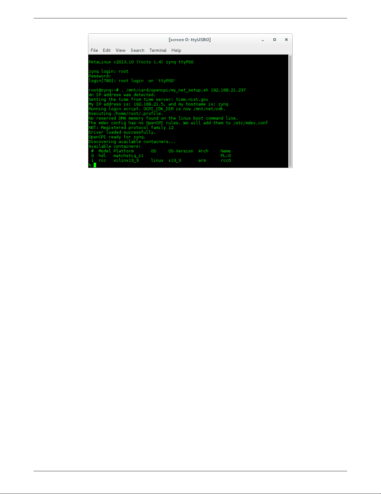
5. After a successful boot to PetaLinux, login to the system, using “root“ for user name and password.
Figure 3: Successful Boot to PetaLinux
6. Setup the OpenCPI environment on remote system
Each time the SDR is booted, the OpenCPI environment must be setup. By sourcing the mynetsetup.sh
script, the remote system’s environment is configured for OpenCPI and NFS directories are mounted for
Network mode.3. The user must provide the network address of the development system to the script as its
only argument:
$ source /mnt/card/opencpi/mynetsetup.sh XX.XX.XX.XX
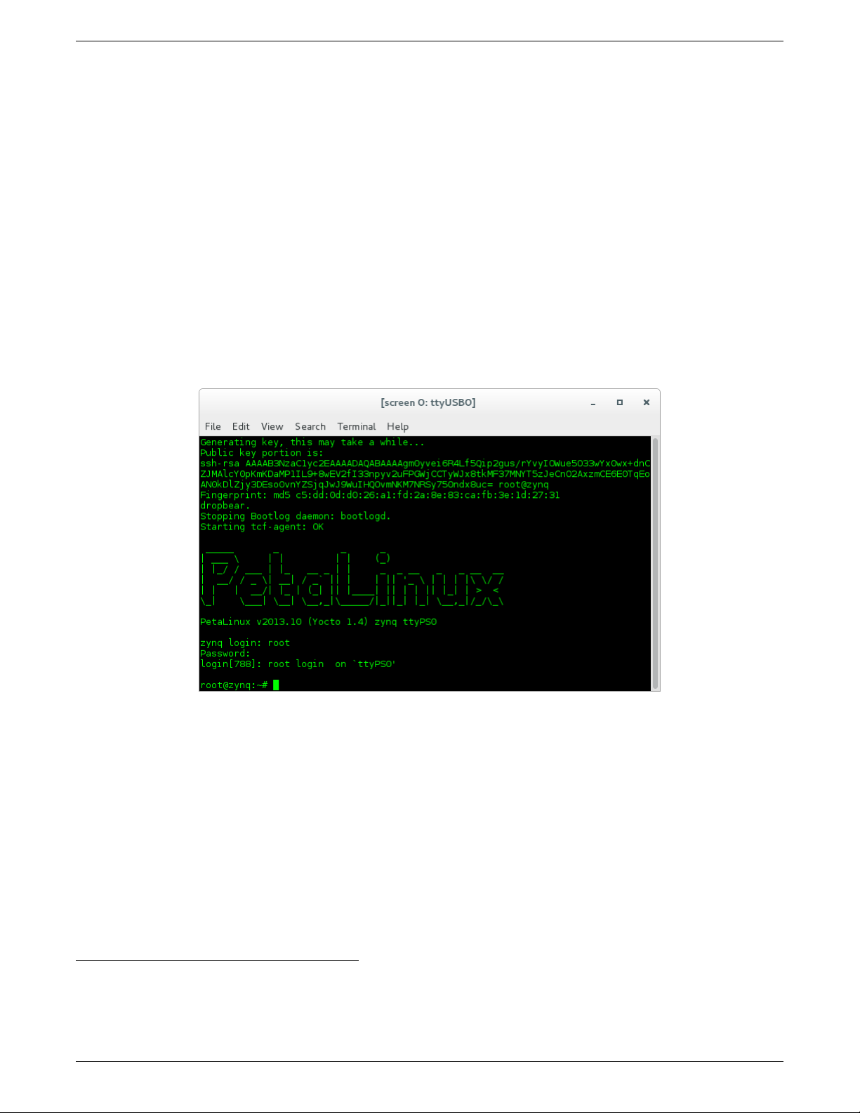
where XX.XX.XX.XX is the IP address of the NFS host (i.e. that development host, e.g. 192.168.1.10). A
successful run is shown in Figure 4.
3
This script calls the zynq_net_setup.sh script, which should not be modifiable by the user.
16
Page 17
Matchstiq-Z1 Getting Started Guide ANGRYVIPER Team
Figure 4: Successful Network Mode Setup
Note: If the output includes:
Attempting to set the time from time server
Alarm clock
ntp was unable to set time using servers in ntp.conf. For more information see Section 5.2
17
Page 18
Matchstiq-Z1 Getting Started Guide ANGRYVIPER Team
8.2 Standalone Mode
All artifacts (.so, .bit.gz) for any applications or tests that need to be located on the SD card must be on the ATLAS
partition in the opencpi/xilinx13_3/artifacts folder. All of the helper utilities such as ocpirun and ocpihdl are
already located on the SD card and do not need to be copied over to the SDR platform.
1. Ensure the USB to Ethernet adapter (as needed) is plugged into the micro-USB p ort of the front panel and
connected to a network configured for DHCP.
2. Ensure a micro-USB to USB cable is connected between the Matchstiq-Z1’s serial port and development host.
3. Apply power to the Matchstiq-Z1
4. Use a serial terminal application to establish a serial connection, for example:
$ screen /dev/matchstiq_z1_0 115200
5. After a successful boot to PetaLinux, login to the system, using “root“ for user name and password.
Figure 5: Successful Boot
6. WARNING: Applications (including XML-only ones) fail if there is not an IP address assigned to the platform,
even when in “standalone mode.” When the Ethernet port is not connected to a network configured with
DHCP, a temporary IP address must be set:
$ ifconfig eth0 192.168.244.244
7. Setup the OpenCPI environment on remote system
Each time the SDR is booted, the OpenCPI environment must be setup. By sourcing the mysetup.sh script,
the remote system’s environment is configured for OpenCPI.4. There are no arguments required for this script.
$ source /mnt/card/opencpi/mysetup.sh
4
This script calls the zynq_setup.sh script, which should not be modifiable by the user.
18
Page 19
Matchstiq-Z1 Getting Started Guide ANGRYVIPER Team
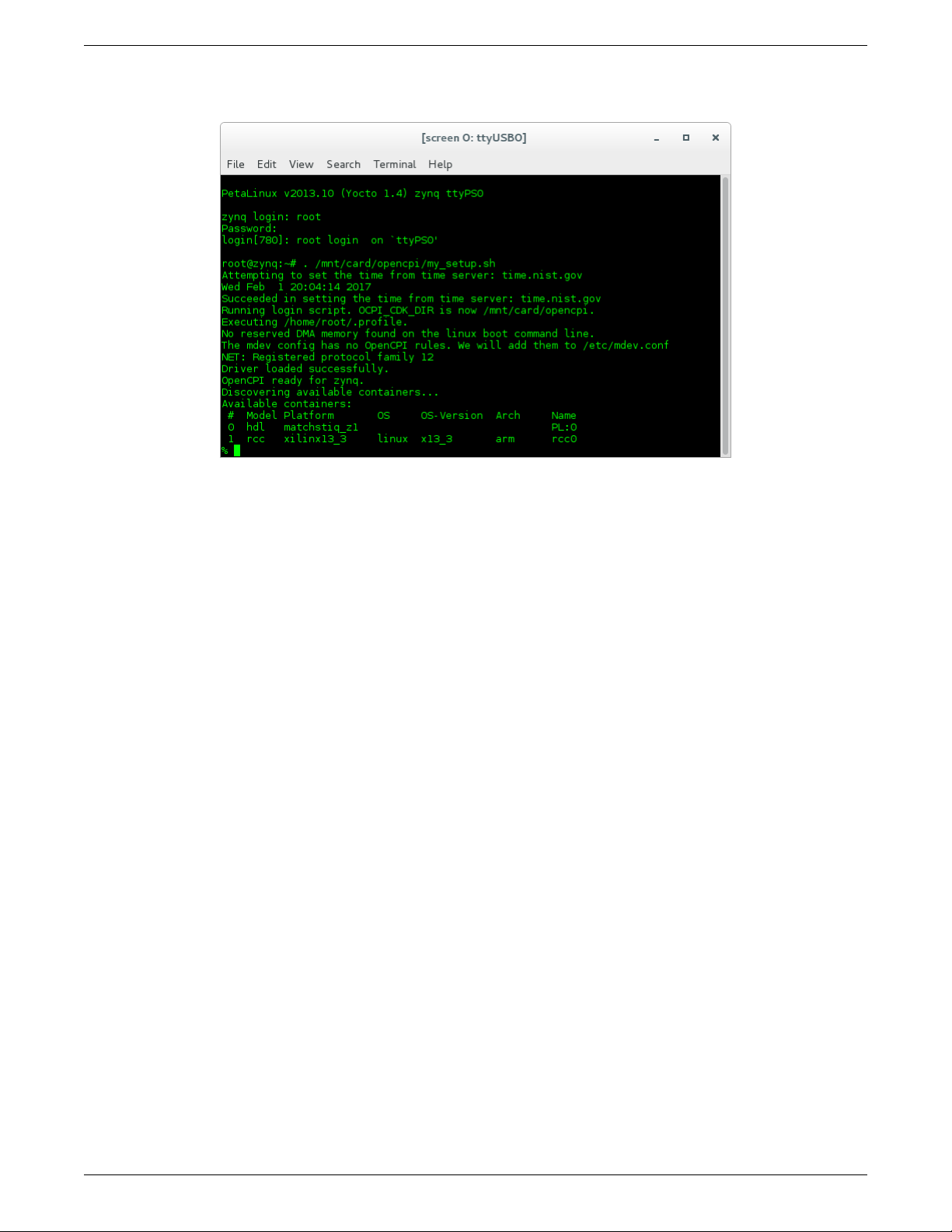
A successful setup of the platform will look as follows:
Figure 6: Successful Standalone Mode Setup
Note: If the output includes:
Attempting to set the time from time server
Alarm clock
ntp was unable to set time using servers in ntp.conf. For more information see Section 5.2
19
Page 20

Matchstiq-Z1 Getting Started Guide ANGRYVIPER Team
9 Build an Application
The setup of the platform can be verified by running an application that uses both RCC and HDL workers. A
simple application that requires two RCC and one HDL worker is located in assets/applications/bias.xml, but
only the RCC artifacts are provided with the installation of RPMs, and are availble on the SD card (Standard
Mode) or mounted CDK directory (Network Mode). The remaining task is to build an assembly, or bitstream for
loading the FPGA, which contains the HDL worker.
10 Run an Application
10.1 Network Mode
The default setup script sets the OCPI_LIBRARY_PATH variable to include the RCC workers that are required to
execute the application, but it must be updated to include to the assembly bitstream that was built. After running
the mynetsetup.sh script, navigate to /mnt/ocpi_assets/applications, then update the OCPI_LIBRARY_PATH
variable:
$ cd /mnt/net/cdk/applications
$ export OCPI_LIBRARY_PATH=$OCPI_LIBRARY_PATH:/mnt/ocpi_assets/artifacts
Run the application using the following command:
$ ocpirun -v -t 1 -d -m bias=hdl bias.xml
The output should be similar to Figure ??:
% ocpirun -v -t 1 -d -m bias=hdl bias.xml
Available containers are: 0: PL:0 [model: hdl os: platform:
matchstiq_z1], 1: rcc0 [model: rcc os: linux platform: xilinx13_3]
Actual deployment is:
Instance 0 file_read (spec ocpi.core.file_read) on rcc container 1: rcc0, using file_read in
/mnt/ocpi_core/artifacts/ocpi.core.file_read.rcc.0.xilinx13_3.so
dated Tue Apr 9 11:34:43 2019
Instance 1 bias (spec ocpi.core.bias) on hdl container 0: PL:0, using bias_vhdl/a/bias_vhdl in
/mnt/ocpi_assets/applications/rx_app/../../artifacts/
ocpi.assets.testbias_matchstiq_z1_base.hdl.0.matchstiq_z1.gz
dated Mon Apr 8 14:31:34 2019
Instance 2 file_write (spec ocpi.core.file_write) on rcc container 1: rcc0, using file_write in
/mnt/ocpi_core/artifacts/ocpi.core.file_write.rcc.0.xilinx13_3.so
dated Tue Apr 9 11:34:48 2019
Application XML parsed and deployments (containers and artifacts) chosen
Application established: containers, workers, connections all created
Communication with the application established
Dump of all initial property values:
Property 0: file_read.fileName = "test.input" (cached)
Property 1: file_read.messagesInFile = "false" (cached)
Property 2: file_read.opcode = "0" (cached)
Property 3: file_read.messageSize = "16"
Property 4: file_read.granularity = "4" (cached)
Property 5: file_read.repeat = "false"
Property 6: file_read.bytesRead = "0"
Property 7: file_read.messagesWritten = "0"
Property 8: file_read.suppressEOF = "false"
Property 9: file_read.badMessage = "false"
Property 10: file_read.ocpi_debug = "false" (parameter)
Property 11: file_read.ocpi_endian = "little" (parameter)
Property 16: bias.biasValue = "16909060" (cached)
Property 17: bias.ocpi_debug = "false" (parameter)
Property 18: bias.ocpi_endian = "little" (parameter)
20
Page 21

Matchstiq-Z1 Getting Started Guide ANGRYVIPER Team
Property 20: bias.test64 = "0"
Property 29: file_write.fileName = "test.output" (cached)
Property 30: file_write.messagesInFile = "false" (cached)
Property 31: file_write.bytesWritten = "0"
Property 32: file_write.messagesWritten = "0"
Property 33: file_write.stopOnEOF = "true" (cached)
Property 34: file_write.ocpi_debug = "false" (parameter)
Property 35: file_write.ocpi_endian = "little" (parameter)
Application started/running
Waiting up to 1 seconds for application to finish
Application is now considered finished after waiting 1 seconds
Dump of all final property values:
Property 3: file_read.messageSize = "16"
Property 6: file_read.bytesRead = "1776"
Property 7: file_read.messagesWritten = "111"
Property 9: file_read.badMessage = "false"
Property 31: file_write.bytesWritten = "1760"
Property 32: file_write.messagesWritten = "110"
21
Page 22
Matchstiq-Z1 Getting Started Guide ANGRYVIPER Team
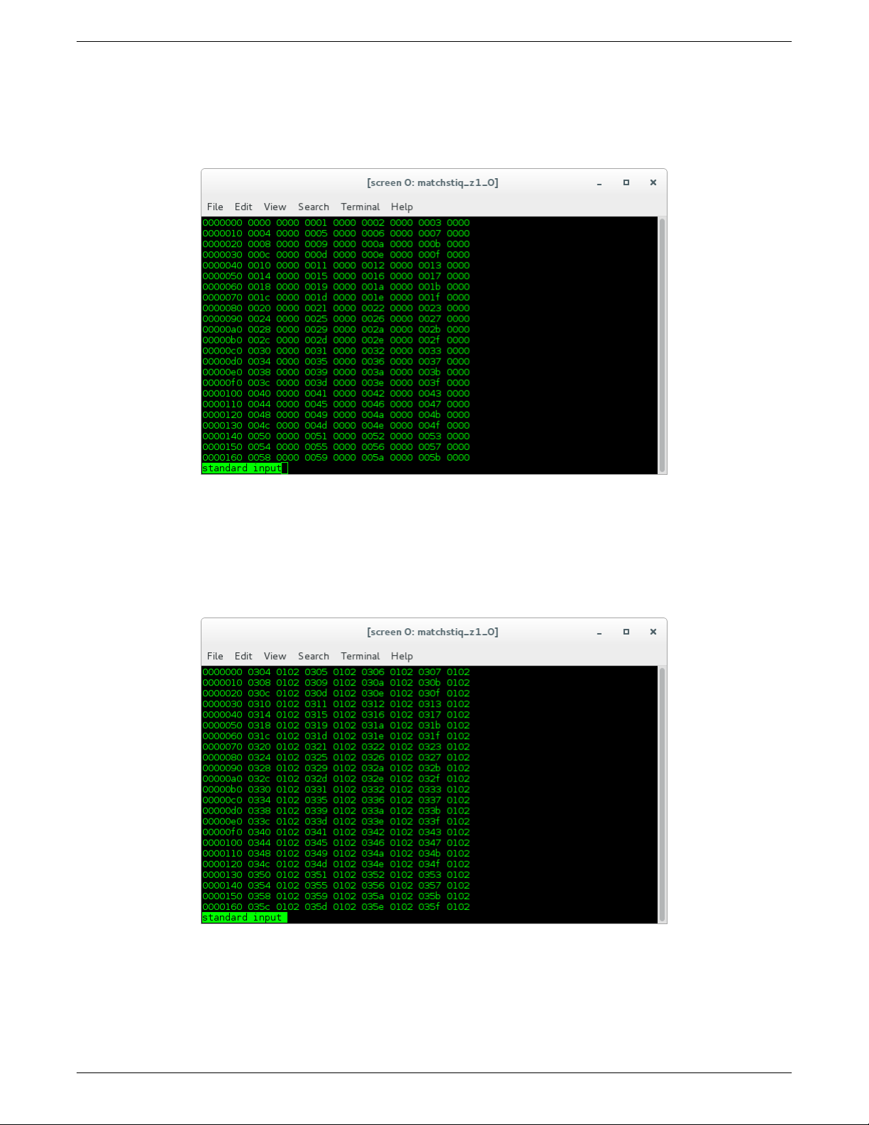
Run the following command to view the input. It should look like Figure 7:
$ hexdump test.input | less
Figure 7: Expected Input
Run the following command to view the output. It should look like Figure 8:
$ hexdump test.output | less
Figure 8: Expected Output
22
Page 23
Matchstiq-Z1 Getting Started Guide ANGRYVIPER Team
10.2 Standalone Mode
The default setup script sets the OCPI_LIBRARY_PATH variable to include the all of the artifacts that are required to
execute the application. Specifically, all three of the artifacts that are located on the SD card are mounted at
/mnt/card/opencpi/xilinx13_3/artifacts. After running mysetup.sh, navigate to
/mnt/card/opencpi/applications and ensure the OCPI_LIBRARY_PATH variable is configure as shown b elow:
$ cd /mnt/card/opencpi/applications
$ export OCPI_LIBRARY_PATH=$OCPI_LIBRARY_PATH:/mnt/card/opencpi/xilinx13_3/artifacts
Run the application using the following command:
$ ocpirun -v -t 1 -d -m bias=hdl bias.xml
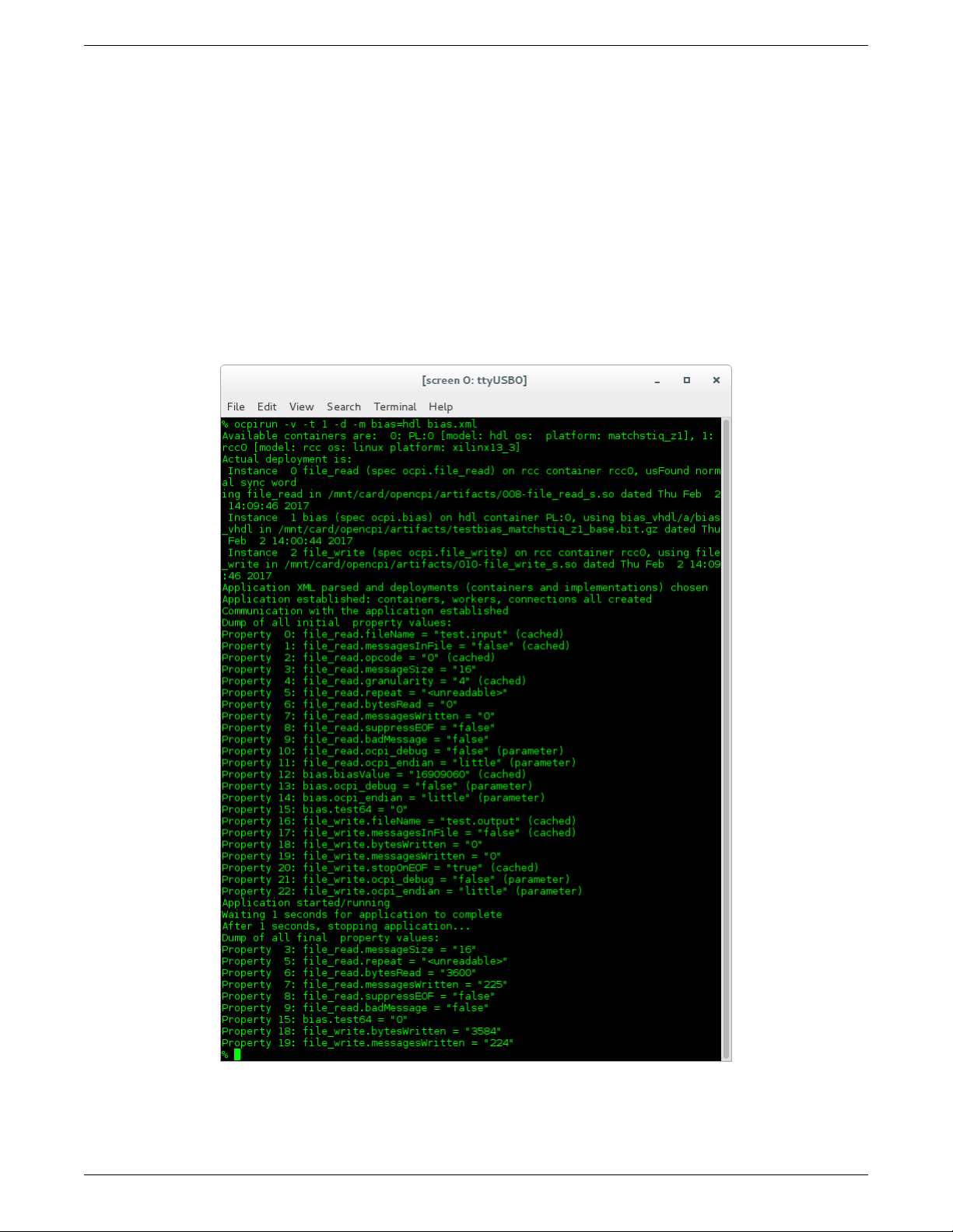
The output should be similar to Figure 9:
Figure 9: Successful Standalone Mode Execution
23
Page 24
Matchstiq-Z1 Getting Started Guide ANGRYVIPER Team
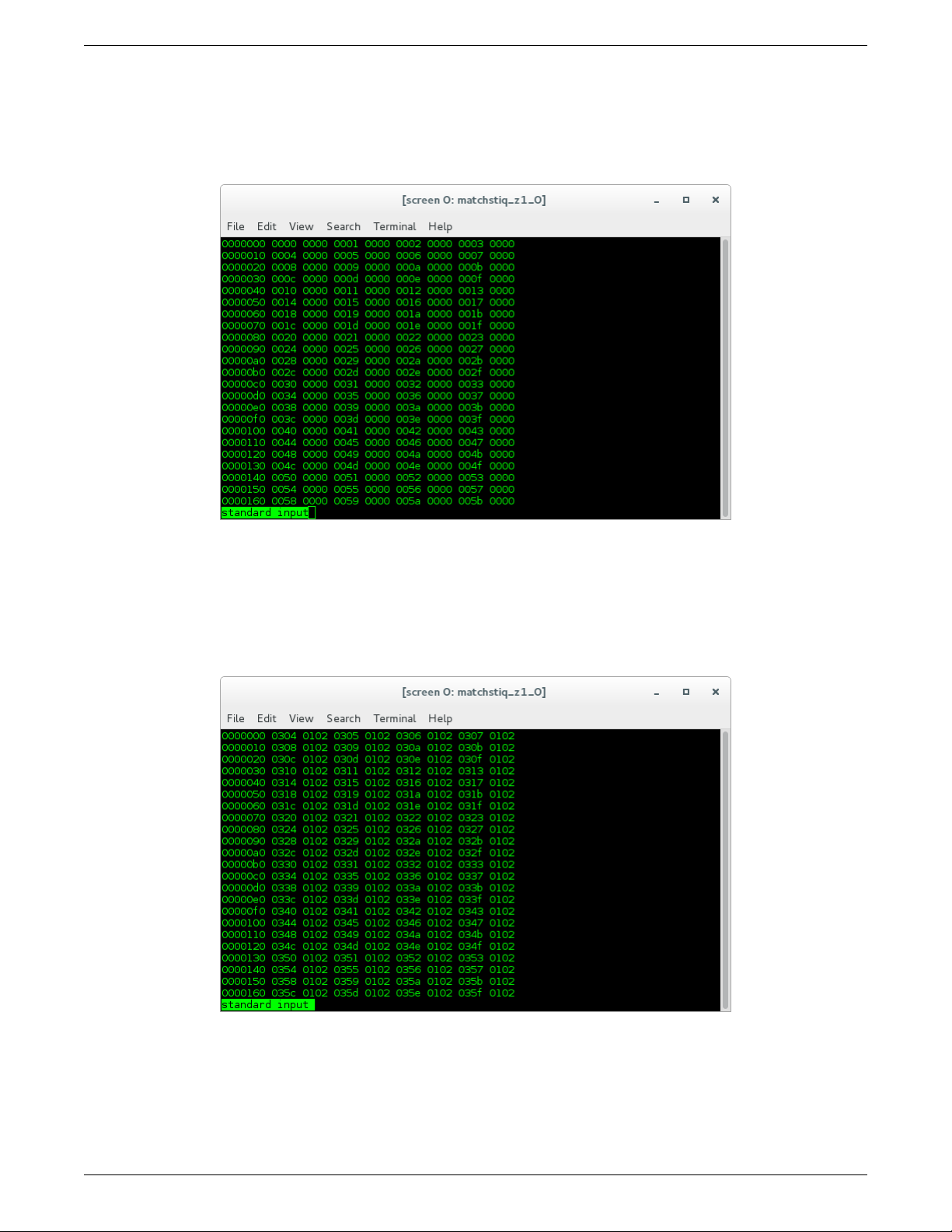
Run the following command to view the input. It should look like Figure 10:
$ hexdump test.input | less
Figure 10: Expected Input
Run the following command to view the output. It should look like Figure 11:
$ hexdump test.output | less
Figure 11: Expected Output
24
Page 25

Matchstiq-Z1 Getting Started Guide ANGRYVIPER Team
Appendices
A Intermittent Errors
Some tests have had “Segmentation Faults” or “Alignment Errors” in certain scenarios on the Z1. This seems to
happen when both USB ports are used to simultaneously transmit a large amount of data, e.g. high log-level output
to a USB serial console as well as NFS-mounted output files over a USB-to-Ethernet adapter. The default test setup
avoids triggering this by limiting output that is fed to the user, but users should be aware of this issue if non-default
test scenarios are attempted. If ssh is used to have all data routed through the USB-to-Ethernet adapter, this failure
mode is avoided.
B Using ISE instead of Vivado with the Matchstiq-Z1
It is recommended that you use the default toolset (Xilinx Vivado) to build Matchstiq-Z1 bitstreams with OpenCPI.
However, if you wish to use ISE instead, reference the README file in assets/hdl/platforms/matchstiq_z1/
ise_constraints/, and perform the following steps:
1. Modify the target part in assets/hdl/platforms/matchstiq_z1/matchstiq_z1.mk to use the ISE alias:
HdlPart_matchstiq_z1=xc7z020_ise_alias-1-clg484
2. Export the ISE constraints files found in <assets/>hdl/platforms/matchstiq_z1/ise_constraints/ by
modifying ExportFiles variable in assets/hdl/platforms/matchstiq_z1/Makefile:
ExportFiles=ise_constraints/matchstiq_z1.ucf ise_constraints/matchstiq_z1.ut matchstiq_z1.mk
C Driver Notes
When available, the driver will attempt to make use of the CMA region for direct memory access. In use cases where
many memory allocations are made, the user may receive the following kernel message:
alloc_contig_range␣test_pages_isolated([memory␣start],␣[memory␣end])␣failed
This is a kernel warning, but does not indicate that a memory allocation failure occurred, only that the CMA engine
could not allocate memory in the first pass. Its default behavior is to make a second pass, and if that succeeded, the
end user should not see any more error messages. This message cannot be suppressed, but can be safely ignored. An
actual allocation failure will generate unambiguous error messages.
25
 Loading...