

Page 1

VGADVI Broadcaster
UserGuide
Version 3.12.0
May 20, 2014
document revision 5
Page 2

Terms and Conditions
This document, the Epiphan web site, and the information contained therein, including but not limited to the
text, videos and images as well as Epiphan System Inc.’s trademarks, trade names and logos are the property of
Epiphan Systems Inc. and its affiliates and licensors, and are protected from unauthorized copying and
dissemination by Canadian copyright law, United States copyright law, trademark law, international
conventions and other intellectual property laws.
Epiphan, Epiphan Systems, Epiphan Systems Inc., and Epiphan logos are trademarks or registered trademarks
of Epiphan Systems Inc., in certain countries. All Epiphan product names and logos are trademarks or
registered trademarks of Epiphan. All other company and product names and logos may be trademarks or
registered trademarks of their respective owners in certain countries.
Copyright © 2014 Epiphan Systems Inc. All Rights Reserved.
THE SOFTWARE LICENSE AND LIMITED WARRANTY FOR THE ACCOMPANYING PRODUCT ARE SET FORTH IN
THE INFORMATION PACKET OR PRODUCT INSTALLATION SOFTWARE PACKAGE THAT SHIPPED WITH THE
PRODUCT AND ARE INCORPORATED HEREIN BY REFERENCE. IF YOU ARE UNABLE TO LOCATE THE SOFTWARE
LICENSES OR LIMITED WARRANTY, CONTACT YOUR EPIPHAN REPRESENTATIVE FOR A COPY.
PRODUCT DESCRIPTIONS AND SPECIFICATIONS REGARDING THE PRODUCTS IN THIS MANUAL ARE SUBJECT
TO CHANGE WITHOUT NOTICE. EPIPHAN PERIODICALLY ADDS OR UPDATES THE INFORMATION AND
DOCUMENTS ON ITS WEB SITE WITHOUT NOTICE. ALL STATEMENTS, INFORMATION AND
RECOMMENDATIONS ARE BELIEVED TO BE ACCURATE AT TIME OF WRITING BUT ARE PRESENTED WITHOUT
WARRANTY OF ANY KIND, EXPRESS OR IMPLIED. USERS MUST TAKE FULL RESPONSIBILITY FOR THEIR
APPLICATION OF ANY PRODUCTS.
LIMITATION OF LIABILITY
UNDER NO CIRCUMSTANCES SHALL EPIPHAN BE LIABLE FOR ANY INCIDENTAL, SPECIAL, CONSEQUENTIAL,
EXEMPLARY OR OTHER INDIRECT DAMAGES THAT RESULT FROM THE USE OF, OR THE INABILITY TO USE, THIS
PRODUCT OR THE INFORMATION CONTAINED IN THIS DOCUMENT OR PROVIDED ON EPIPHAN’S WEB SITE,
EVEN IF EPIPHAN HAS BEEN ADVISED OF THE POSSIBILITY OF SUCH DAMAGES. IN NO EVENT SHALL EPIPHAN’S
TOTAL LIABILITY TO YOU FOR ALL DAMAGES, LOSSES, AND CAUSES OF ACTION RESULTING FROM YOUR USE
OF THIS PRODUCT, WHETHER IN CONTRACT, TORT (INCLUDING, BUT NOT LIMITED TO, NEGLIGENCE) OR
OTHERWISE, EXCEED THE AMOUNTS YOU PAID TO EPIPHAN DURING THE MOST RECENT THREE-MONTH
PERIOD IN CONNECTION WITH AMOUNTS WHICH YOU PAID FOR USING THIS PRODUCT.
INFORMATION AND DOCUMENTS, INCLUDING PRODUCT SPECIFICATIONS, PROVIDED IN THIS DOCUMENT OR
THE EPIPHAN WEB SITE ARE PROVIDED “AS IS”. SPECIFICALLY, BUT NOT WITHOUT LIMITATION, EPIPHAN DOES
NOT WARRANT THAT: (i) THE INFORMATION IS CORRECT, ACCURATE, RELIABLE OR COMPLETE; (ii) THE
FUNCTIONS CONTAINED ON THE EPIPHAN WEB SITE WILL BE UNINTERRUPTED OR ERROR-FREE; (iii) DEFECTS
WILL BE CORRECTED, OR (iv) THIS WEB SITE OR THE SERVER(S) THAT MAKES IT AVAILABLE ARE FREE OF
VIRUSES OR OTHER HARMFUL COMPONENTS. EPIPHAN SPECIFICALLY DISCLAIMS ALL REPRESENTATIONS,
WARRANTIES, AND CONDITIONS, EITHER EXPRESS, IMPLIED, STATUTORY, BY USAGE OF TRADE OR OTHERWISE
INCLUDING BUT NOT LIMITED TO ANY IMPLIED WARRANTIES OF MERCHANTABILITY, NON-INFRINGEMENT,
TITLE, SATISFACTORY QUALITY OR FITNESS FOR A PARTICULAR PURPOSE.
For additional terms and conditions, please refer to additional sections in this document.
i
Page 3

Thank You forChoosingEpiphan!
At Epiphan Systems Inc. (“Epiphan”), product function and quality are our top priority. We make every effort to
make sure that our products exceed your expectations.
Product Feedback
Your feedback is important! We regularly contact our customers to ensure our products meet your
performance and reliability requirements. We strive to continually enhance our products to accommodate your
needs. Please let us know how you think we can improve our products by emailing your suggestions to
info@epiphan.com.
Specifications
Go to the Broadcasters page of the Epiphan website to get the most recent product specifications and
additional information about the VGADVI Broadcaster.
Warranty
All Epiphan Systems products are provided with a 100% return to depot warranty for one year from the date of
purchase.
Technical Support
Epiphan’s products are backed by our professional support team. If you are having issues with your product,
please gather details about your system and contact our team by:
l Emailing support@epiphan.com
l Live chat via the link on our support site http://www.epiphan.com/support/
l Phone toll free at 1-877-599-6581 or call +1-613-599-6581
Be sure to include as much information about your problem as possible. Including:
l Problem description
l Details of the video or audio source (type, connection, resolution, refresh rate, etc.)
l Product serial number
l Product firmware version (if applicable, from web admin interface)
l Product LED lights
Copyright © 2014 Epiphan Systems Inc. All Rights Reserved.
ii
Page 4

What's New in Release 3.12.0
The following features were introduced or in some cases enhanced in release 3.12.0. For a description of new and
changed features in previous releases refer to Releases and Features .
New Streaming Features
RTMP live streaming
Your can now stream live video to a content delivery network using Real Time Messaging Protocol (RTMP). In addition
to providing high performance streaming of audio and video, when you stream your content using RTMP, you reduce
system resource usage as well as enhance your viewer's experience.
When setting your CDN, you now have a choice between streaming with RTSPannouncement or RTMP push. Both
RTSP and RTMP can be used for live streaming, however not all CDNs or media servers support both formats.
See Stream content using HTTP or RTSP.
SAP Announce
Your allows you to advertise your stream over a local network using SAP Announce. To use this feature, your stream
must be setup to use UDP streaming. Local viewers can view the stream using a software or hardware media player.
Viewers are presented with a list of available channels, similar to a television listing. Viewers need only click on a stream
or channel and the video is streamed to their desktop, mobile or tablet.
See Stream content using multicast streaming.
See Add a customized background to a multi-view channel.
Page 5

Table Of Contents
Thank You forChoosingEpiphan! ii
Product Feedback ii
Specifications ii
Warranty ii
Technical Support ii
Welcome 1
About this Guide 1
VGADVI Broadcaster Overview 3
What's in the Box? 4
VGADVI Broadcaster Overview 5
Quick Start 8
Step 1: Physical setup and power on 8
Step 2: Confirm signals from input sources 9
Step 3: Admin discovery and login 9
Step 4: Setup the video source 10
Step 5: Configure the channel 10
Step 6: Record the stream 11
What’s Next? 11
PART 1: Setup 13
1-1 Connect to the Admin Interface 14
Connect via DNS-based Service Discovery 14
Connect via the Epiphan Discovery Utility 16
Connect via Persistent Static IP Address 17
1-2 User Administration 19
Understanding User Privileges 19
Setting and Changing User Passwords 21
Removing User Passwords 22
Overcoming Lost Passwords 23
Changing the logged-in user 23
1-3 Configure Network Settings 25
Verify IP Address and MAC address 25
Configure a Static IP Address 26
Configure DHCP 28
Tether to a Mobile Network 29
Perform Network Diagnostics 30
1-4 Configure Date and Time 32
iv
Page 6

Verify Date and Time Settings 32
Change the Time Zone 34
Configure Synchronized Time (NTP, PTP v1, and RDATE) 34
Manually Configure the Date and Time 36
1-5 Restrict Viewers by IPAddress 37
Examples 38
PART 2: Sources 41
2-1 Identify sources 42
2-2 Configure a video source 43
2-3 Configure an audio source 45
Add an audio source to a channel 45
Configure audio settings 45
Set audio volume 46
View audio signal strength 47
2-4 Fine-tune source configuration 49
Force the video source to use a specific resolution 52
PART 3: Channels 54
3-1 Configure channels 55
Create a DVI channel 55
Create a Video channel 57
Configure picture in picture or picture with picture layout 60
Enable and disable a channel 62
3-2 Fine-tune channel configuration 63
Choose a codec to maximize your stream quality 63
Codec and file format compatibility 65
Adjust video quality 66
Upscale or downscale your video image 68
Control the matte (black bars) in the video output 69
Unstretch the output video 72
Limit the frame rate 72
Adjust key frame interval 73
3-3 Customize your channel 75
Add your logo and company information to your channel 75
Add a time stamp to your channel 81
Select the background color for your channel 82
PART 4: Stream 83
4-1 Stream your video 84
View available video formats 84
Choose a streaming option 85
v
Page 7

Retrieve stream URLs 88
Configure streaming ports 89
Stream content using HTTP or RTSP 90
Stream content using a Content Distribution Network 90
Stream content using multicast streaming 97
Stream content using UPnP 101
4-2 Samples of stream settings 105
Streaming video content 105
Streaming slide content 106
PART 5: Record 107
5-1 Create Recordings 108
Recording basics 108
Control recording via the web interface 108
Configure thetype and length of recording files 109
Close the current recording file while recording 111
Control recording with a mouse 111
Control recording with on-device buttons 111
Control recording with a USB keyboard or mouse 113
5-2 File Maintenance 115
View the List of Stored Files 115
Rename Stored Files 116
Download Files Manually 117
Delete Files Manually 117
5-3 File and Recording Transfer 119
Configure Automatic File Upload (Part 1 of 2) 119
Configure Automatic File Upload to an FTP Server (Part 2 of 2) 121
Configure Automatic File Upload using RSync (Part 2 of 2) 122
Configure Automatic File Upload using CIFS (Part 2 of 2) 124
Upload to an External USB Drive 125
5-4 Use the Local FTPServer 131
Configure the Local FTP Server 131
Downloading Files from the Local FTP Server 132
PART 6: View 135
6-1 View your video 136
View the live broadcast and retrieve stream URLs 136
Viewing with a web browser 138
Viewing with a media player 139
Viewing with UPnP 140
Viewing with Session Announcement Protocol (SAP) 141
PART 7: Maintenance 144
vi
Page 8

7-0 Mobile / Tablet Operator Interface 145
Connect to the tablet interface 145
Confidence monitoring using the tablet interface 147
Verify disk space via the tablet interface 148
Control recording via the tablet interface 149
Switch to the full admin interface 149
7-1 Power Down and System Restart 151
Restarting the Device via the Web Interface 151
7-2 Save and Restore Device Configuration 152
Save device configuration 152
Load a saved device configuration 153
7-3 Restoring Factory Configuration 155
Restore Factory Configuration via the Web Interface 155
Restore Factory Configuration Manually 156
7-4 Firmware Upgrade 158
Check for Firmware Updates 158
Install firmware 158
7-5 Remote Support 162
Configure Remote Support 162
Disable Remote Support 164
7-6 Storage Disk Maintenance 165
Check disk storage space 165
Schedule disk check 166
Perform disk check 166
7-7 Control with RS-232 / Serial Port 169
Connect and Configure the RS-232 cable 169
Control the VGADVI Broadcaster with RS-232 170
RS-232 / SerialPort Command Examples 171
7-8 Control with HTTPCommands 173
HTTP Command Syntax 173
HTTP Command Examples 174
7-9 ConfigurationKeys forThirdParty APIs 176
System-level Settings Keys(Read-only) 177
System-level SettingsKey (Read/Write) 177
Recording Configuration Keys 178
HTTPServer Configuration Keys 178
IP-Based Access Control Configuration Keys 179
UPnP Configuration Keys 179
Frame Grabber Configuration Keys 179
vii
Page 9

Broadcast ConfigurationKeys 180
Channel Encoder ConfigurationKeys 181
Channel Logo Configuration Keys 182
Channel Layout Configuration Keys 183
Audio Configuration Keys 184
Stream Publishing Configuration Keys 184
RTSPAnnounce Configuration Keys (Publish Type 2) 185
RTP/UDPConfiguration Keys (Publish Type 3) 186
MPEG-TSConfiguration Keys (Publish Types 4 and 5) 186
RTMPPush Configuration Keys (Publish Type 6) 186
ContentMetadata Configuration Keys 187
7-10 Troubleshooting 188
PART 8: Releases and Features 190
Release 3.11 Features 190
Software and Documentation License 193
Environmental Information 197
FCC & CE Compliance Statement 197
Other Jurisdictional Issues 198
Submissions to Epiphan and Affiliated Servers 198
Third Parties and Links to Third-Party Web Sites 198
Miscellaneous 198
Enforcement of Terms and Conditions 199
viii
Page 10

Welcome
Welcome, and thank you for buying Epiphan’s VGADVI Broadcaster™. This guide will help you configure your new
system.
To get started, review the VGADVI Broadcaster Overview and What's in the Box? sections. Next, a Quick Start guide
walks you through the basic steps to get a single video (and optional audio) source configured as a streamable,
recordable output from the VGADVI Broadcaster.
Following the quick start section, a set of task-based procedures help you to tweak the system exactly how you want it.
These procedures are broken into seven categories: Setup, Sources, Channels , Stream, Record, View, and Maintenance.
About this Guide
Warnings are depicted as follows.
This is a warning.
Tips and Notes are depicted as follows.
Page 11

This is a tip.
Throughout this guide there are situations where more than one solution will complete a task. In those cases the
guide describes the simplest or most common variation first.
Page 12

VGADVI Broadcaster Overview
VGADVI Broadcaster is a small, silent, portable video recording and video streaming device that captures and streams
audio, SDvideo sources like camera feeds, and HD video sources such as computer monitors, RADARdisplays, or
ultrasound machines. You can use it to capture, record, and stream one input or both inputs simultaneously as
synchronized time-stamped streams or a picture-in-picture stream. The stream can be viewed a number of ways
through media players, browsers, or on mobile devices. Recorded files can be downloaded via FTPor set to
automatically upload via FTP, RSYNC, or CIFS.
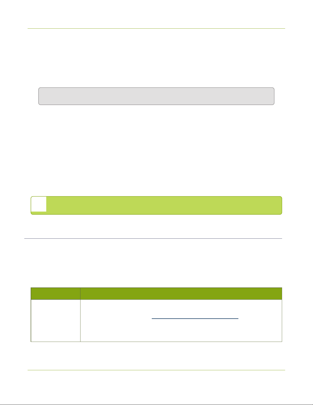
The following table describes the storage capacity and types of inputs support by the VGADVI Broadcaster.
Table 1 Inputs and Storage specifications for VGADVI Broadcaster
Model
VGADVI Broadcaster
DVI-I
(single link)
1 - 1 1 8 GB
DVI-I
(dual link)
S-Video Audio Storage
Page 13

What's in the Box?
The following is included in the VGADVI Broadcaster box:
1. The VGADVI Broadcaster device
2. One VGA to DVI-I cable
3. One HDMI to DVI-I adapter
4. One DVI-I to DVI-I cable
5. One composite to S-Video cable
6. One Ethernet cable
7. One Power over Ethernet injector
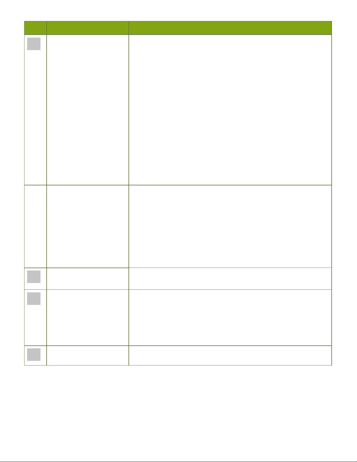
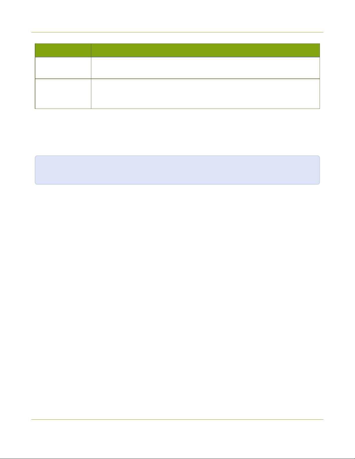
Table 2 Description of Included Cables (Images are for cable type identification, actual cable appearance may vary.)
Image Name Description
DVI-I Dual Link cable Connects a DVI source to the system’s DVI port(s).
VGA to DVI cable Connects a VGA source to the system’s DVI port(s).
HDMI to DVI adapter Connects an HDMI source to the system’s DVI port(s).
Composite to S-Video cable
RJ-45 Ethernet cable Connects the system to your network.
Power over Ethernet injector
Connects a composite output from an analog sources to
the system’s S-Video port(s).
Injects power over an Ethernet cable. Used to power the
device when the network connection is not powered.
Page 14
VGADVI Broadcaster Overview
The VGADVI Broadcaster is suitable for setting on a desktop, shelf or podium. It’s small size (202mm x 105mm x 35mm
(7.95” x 4.13” x 1.38”) provides the user with the flexibility of having it within arm’s reach, yet remain inconspicuous. For
ease of use all input connections are accessible from the front panel and LEDs are displayed on the front panel. The
back panel provides connections for output devices and power.
Front Panel
This section describes the front panel connectors and indicators.
Table 3 VGADVI Broadcaster Front Panel Descriptions
Label Name Description
Reset button Resets the VGADVI Broadcaster back to its factory configuration defaults.
To ensure the device is not accidentally reset, a special sequence is required.
See Restoring Factory Configuration.
Record Stop/Start toggle
Toggles the recording on/off.
Page 15
Label Name Description
Status LEDs Three LEDs on the front panel indicate the following VGADVI Broadcaster
status:
Solid blue LED indicates device is starting up or indicates a recording error
during a recording session.
Solid green LED indicates the device is ready to capture images.
Flashing green LED indicates files are copied to an external USB drive.
Flashing blue LED indicates:
l a video signal test is in progress;
l system tuning, or
l VGADVI Broadcaster is recording received images.
Note: If the periodic disk check function occurs during start up, it may take
up to 20 minutes to power up the device. During this time the blue LED is
flashes (two intermittent flashes) and the green LED flashes. See Storage
Disk Maintenance for more information.
USB port Connect to one of the following devices:
l big red button for recording control
l external HDD
l USB flash drive
l mouse to start and stop recording
l RS-232 serial port for remote control
Note: Using more than one USB device may impact system performance.
S-Video input Connect to an s-Video source or a composite video source using the
adapter (included).
DVI-I input port Connect to one of the following sources:
l DVI input, use the DVI to DVI cable (included)
l VGA input, use the VGA to DVI adapter (included)
l HDMI input, ( for non-copy protected content), use the HDMI to DVI
adapter (included)
Audio In
Connect to an audio input source.
Back Panel
This section describes the back panel connectors and indicators.
Page 16
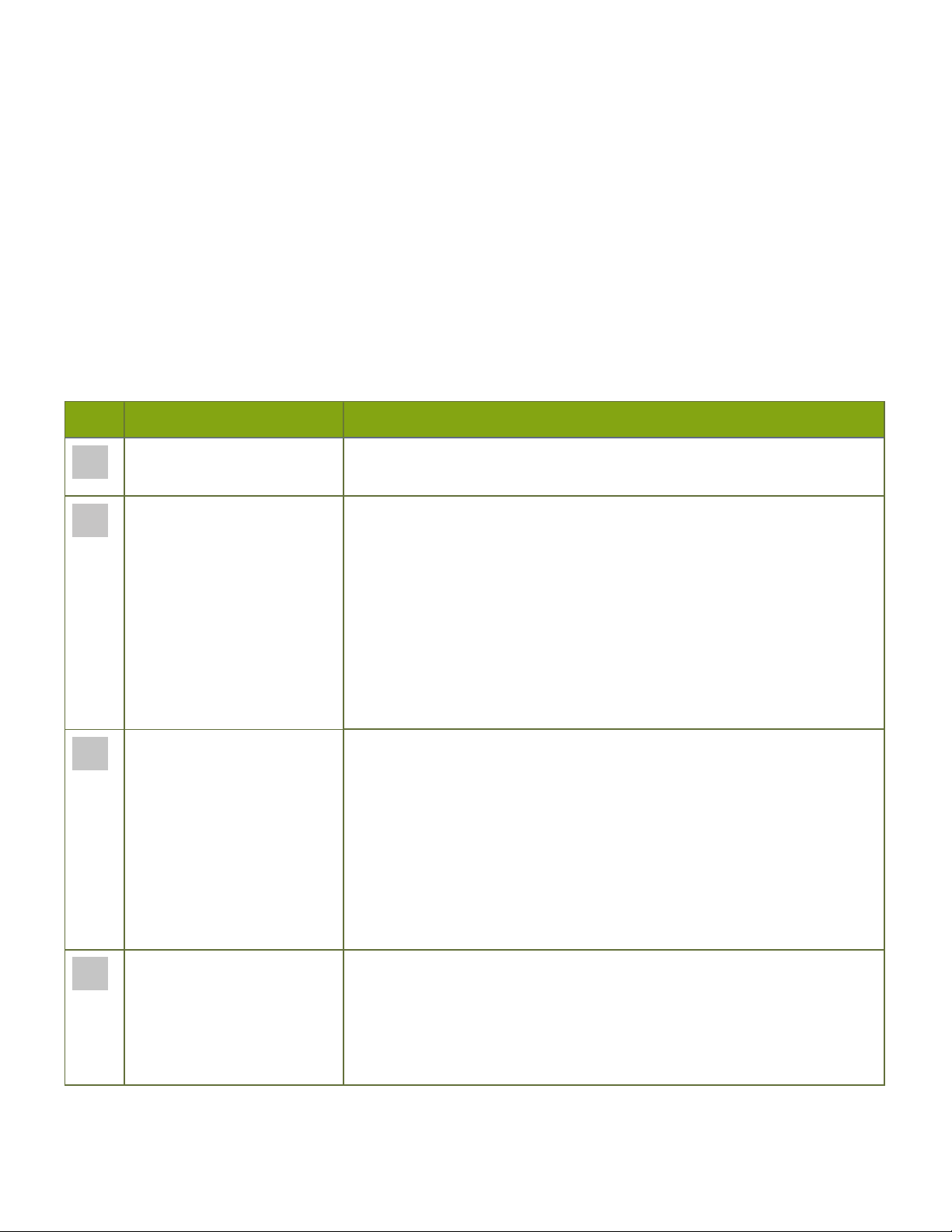
Table 4 VGADVI Broadcaster Back Panel Descriptions
Label Name Description
Audio Out Connect to audio equipment, such as headphones or speakers, to confirm
the audio stream is captured.
DVI Out Connect to video equipment, such as a monitor or projector to confirm the
video stream is captured.
Connect one of the following sources:
DVI output, use the DVI to DVI cable (included)
VGA output, use the VGA to DVI cable (included)
Note: This connection can convert a VGA input signal to DVI output signal.
To confirm the video stream from an s-Video port, refer to Configure
channels.
USB Connect to one of the following devices:
l big red button for recording control
l external HDD
l USB flash drive
l mouse to start and stop recording
l RS-232 serial port for remote control
Note: Using more than one USB device may impact system performance.
RJ-45 Attach the provided RJ-45 cable and connect to a powered Ethernet port.
The port is auto-sensing and supports negotiations at 10/100 speeds.
Power over Ethernet is used to power VGADVI Broadcaster. If the network
connection does not provide power, use the provided power over Ethernet
injector to power the device.
Page 17

Quick Start
This section helps you get up and running quickly with your VGADVI Broadcaster:
l Step 1: Physical setup and power on
l Step 2: Confirm signals from input sources
l Step 3: Admin discovery and login
l Step 4: Setup the video source
l Step 5: Configure the channel
l Step 6: Record the stream
Before you get started, make sure you have:
l an HD source (i.e. a computer, a tablet, or a phone)
l the appropriate cables or adapters to convert the output to DVI (if needed)
l optionally, an audio source such as a microphone or the headphone jack from a laptop (note that the audio
signal sent over HDMI cables is not supported)
l ideally, a network with Dynamic Host Configuration Protocol (DHCP)
l a computer with a web browser connected to the same network (this is referred to as the “admin” computer in
the steps below)
These instructions include steps for setting up and configuring audio. Skip these optional steps if you do
not want to configure an audio source at this time.
Step 1: Physical setup and power on
Complete the following steps to prepare and power on the system. Refer to the Front and Back Panel View section for
your system to locate the appropriate ports.
1. Turn on your HD source and connect the output cable to the DVI-I input port on the front of the device.
2. (optional) Attach a 3.5 mm audio cable from your audio source to the system’s audio input port.
3. If your network connection provides power overEthernet:
a. Connect the Ethernet cable to the system.
b. Connect the Ethernet cable to your network.
If your network connection does not provide power over Ethernet:
a. Connect the PoE injector into a grounded AC power source.
b. Connect an Ethernet cable from the Ethernet switch port on your network to the RJ-45 connector
(labeled In) on the PoE injector.
c. Connect an Ethernet cable from the RJ-45 connector (labeled Out) from the PoE injector to the RJ-45
Ethernet port on the back panel of the VGADVI Broadcaster.
Page 18
4. Wait for the system to complete the power up sequence. The green power LED is illuminated when boot up is
complete.
Step 2: Confirm signals from input sources
Once the VGADVI Broadcaster is powered up, you can confirm that signals from input sources are received by the
device.
1. To ensure an input source is properly connected to the DVI input port, connect a monitor to the DVI output
port on the VGADVI Broadcaster.
2. View the monitor to confirm a signal is sent to the DVI input port.
3. To confirm high quality data is captured from an S-video input source, connect the source to an S-video or
composite receiver, such as a TV or monitor before connecting to the VGADVI Broadcaster and confirm that a
high quality signal is generated.
4. To ensure an audio signal is sent to the VGADVI Broadcaster, connect a speaker or headset to the audio output
port and listen to the captured audio.
Now you are ready to capture, record and stream.
Step 3: Admin discovery and login
The VGADVI Broadcaster is managed from a web interface. This interface acts as a configuration utility and system
monitor. The first time you access the web interface you may not know the IP address of the device.
The steps below use DNS-based service discovery (a type of zero-configuration networking) to access the device.
Depending on the operating system on your admin computer you may need to install some software before you can
use DNS-based discovery.
Table 5 Installing Bonjour Print Services
System Action Needed
Microsoft Windows You must install Bonjour Print Services:
1. Use the following URL - http://support.apple.com/kb/DL999
2. Click Download.
3. Follow the system prompts to download and install the application.
MacOSX The Bonjour software used for service discovery is built into the Mac OS. No special actions are
needed.
Linux The Avahi implementation used for DNS-based discovery is shipped with most Linux
distributions. If necessary, check with your administrator to ensure you have the Avahi
package installed.
This quick start is meant for systems that support DHCP and DNS, however if your system does not support
either protocol, refer to Connect to the Admin Interface for other discovery methods. Return here when
prompted for the web interface user name and password.
Page 19

You are able to access the system's web interface on the local network by specifying its serial number in a web browser
on your admin computer.
1. Find the system’s serial number. It is printed on a sticker on the back of the device.
2. Type the following string into the address bar of your web browser on your admin computer and press Enter.
(<serial> is the serial number of your VGADVI Broadcaster):
http://<serial>.local/admin
For example: http://3D24A1.local/admin
3. Enter the user name and password then click OK. The administrative user is ‘admin’. Initially no password is set.
To set a password follow the procedure outlined in Setting and Changing User Passwords.
4. Optionally, navigate to the Network link under the Configuration heading and note the IP address of the
system.
Step 4: Setup the video source
When a source device, such as a camera or tablet is connected to an input port, the VGADVI Broadcaster automatically
recognizes the source and adds the source to the Stream Setup menu in the Web Interface.
1. From the web interface, click on the Info page; the info page opens displaying the live stream and the stream
URL. This is the link you can share with your viewer to view the live broadcast.
Source setup is complete. The system automatically detected and adjusted the image capture settings at start up and
will continue to adjust every 60 seconds during operation (interval is configurable). The system’s goal is to produce the
best quality captured image given the source equipment used. Generally no further configuration tweaks are needed.
Step 5: Configure the channel
Now that you confirmed the system detected your source and you are satisfied with the captured image, it’s time to
configure a channel to share the captured image with your streaming users and prepare the source for recording.
Review and configure the channel:
Page 20

1. From the web interface, click Stream Setup. The Steam Setup page opens displaying configuration settings for
DVI and S-Video channels.
2. No need to change anything right now. Review some of the default settings. The four most useful settings to
know about are codec, frame size, frame rate and bitrate.
a. The codec is set to H.264 by default.
b. The frame size should reflect the resolution provided by your source. You can set it to something different
by typing in the fields or selecting an option from the different sizes shown. Scaling the image (making it
larger, smaller, or different aspect ratio) takes some processing power, so it’s always best to leave this at
the value detected by the system unless you know it is wrong or know you need to scale the size.
c. The frame rate limit is set to 30. This means the system won’t spend extra computing time to attempt to
receive more than 30 frames per second. For perspective, NTSC TV signals use 24 frames per second and
most hand-drawn animations show only 12 unique frames per second.
d. The bitrate is automatically calculated based on the resolution of the input signal. Raising this value uses
more system processing power and more bandwidth.
You may now optionally add audio to your channel:
3. Scroll to the bottom of the Stream Setup page and ensure the Enable audio checkbox is enabled (enabled by
default) for the audio source to which you connected your 3.5 mm audio cable.
4. Leave the default PCM 22KHz format and audio bitrate.
5. Click Apply.
Your stream setup is complete. Since most of the steps are pre-configured; you are up and running with a stream very
quickly. You can share the live broadcast link with your viewers on your local area network (LAN). Depending on your
internet connection and upstream bandwidth, you may need to adjust the video bitrate down before sharing over the
internet.
Step 6: Record the stream
The device is set up and streaming. This may be all you need, but if you like, you can also record the stream.
To record the stream:
1. From the web interface, click the red Start button at the top of the menu; the text at the top of the screen
changes to indicate the recording is starting, then indicates the length of time since the recording started.
2. Click the black Stop button; the recorder stops.
3. To view the result, click RecordedFiles; the recorded files page loads and a file list appears that displays your
newly recorded stream snippet.
4. Click the file name to download and view your recording.
What’s Next?
Now that you have a source setup and ready to stream, you can fine-tune the system to your exact requirements. You
can look at topics such as:
l Customize your channel
l Stream your video
Page 21

l File and Recording Transfer
l User Administration
When you have completed system tuning, make sure to back up the device configuration using the procedure
described in:
l Save and Restore Device Configuration
Refer to the table of contents for a complete list of the topics covered.
Page 22

VGADVI Broadcaster User Guide PART 1: Setup
PART 1: Setup
If you followed through the quick start guide, you already have a basic configuration and possibly a recording
of an input. Before you tweak the channel this part of the manual helps you to get your VGADVI Broadcaster
properly configured for your network.
Topics covered:
l Connect to the Admin Interface
l User Administration
l Configure Network Settings
l Configure Date and Time
l Restrict Viewers by IPAddress
13
Page 23
VGADVI Broadcaster User Guide 1-1 Connect to the Admin Interface
1-1
The VGADVI Broadcaster is managed from a web interface. If you know the IP address of the device you may
type it into the address bar of your web browser.
The first time you access the web interface you may not know the IP address of the device. The VGADVI
Broadcaster supports a number of ways to determine the IP address.
This section covers two discovery methods that work with networks that support Dynamic Host Configuration
Protocol (DHCP) and a method that works for networks that do not support DHCP.
For networks with DHCP use one of the following procedures:
For networks without DHCP, use the following procedure:
Connect to the Admin Interface
http://<IP Address of the VGADVI Broadcaster>/admin
l Connect via DNS-based Service Discovery
l Connect via the Epiphan Discovery Utility
l Connect via Persistent Static IP Address
You can also connect to a reduced Operator tablet interface. See Connect to the tablet interface
Connect via DNS-based Service Discovery
The VGADVI Broadcaster uses DNS-based messages to advertise details about itself, including its domain
name. With a compatible utility installed on your computer, you can access the device simply by typing its serial
number and the suffix “.local” into the address bar of your browser.
To ensure you have compatible software, refer to the following table.
Table 6 Installing Bonjour Print Services
System Action Needed
Microsoft Windows You must install Bonjour Print Services:
1. Use the following URL - http://support.apple.com/kb/DL999
2. Click Download.
3. Follow the system prompts to download and install the application.
14
Page 24
VGADVI Broadcaster User Guide 1-1 Connect to the Admin Interface
System Action Needed
MacOSX The Bonjour software used for service discovery is built into the Mac OS. No special
actions are needed.
Linux The Avahi implementation used for DNS-based discovery is shipped with most Linux
distributions. If necessary, check with your administrator to ensure you have the Avahi
package installed.
To access the VGADVI Broadcaster web interface via DNS service discovery:
1. Find the system’s serial number. It is printed on a sticker on the back of the unit.
2. Type the following string into the address bar of your web browser on your admin computer (where
<serial> is the serial number of your VGADVI Broadcaster):
http://<serial>.local/admin
For example: http://95dd40d5.local/admin
3. Enter the user name and password then click OK. The administrative user is ‘admin’. Initially no
password is set. To set a password follow the procedure outlined in Setting and Changing User
Passwords.
4. Optionally, navigate to the Network link under the Configuration heading and note the IP address of
the system.
15
Page 25

VGADVI Broadcaster User Guide 1-1 Connect to the Admin Interface
Connect via the Epiphan Discovery Utility
Epiphan provides a utility for discovering Epiphan devices on your network. The Epiphan network discovery
utility is a 32-bit Windows executable that works on most 32-bit and 64-bit Windows operating systems.
Download and install the utility via the download link on this web page:
http://www.epiphan.com/products/broadcasting/resources.
To access the VGADVI Broadcaster web interface via the Epiphan discovery utility:
1. Launch the discovery utility.
2. Click Search to find all the Epiphan devices on the network; a list similar to the following appears.
3. If more than one device appears, select the one you wish to configure by matching the serial number
listed with the serial number marked on the back of the device.
4. Optionally, note the IP Address shown in the stream properties. Use this for quicker access to the device
on future configuration sessions.
5. Click the Web config button; your browser will open and point to the web interface page.
http://<IP Address of the VGADVI Broadcaster>/admin
6. Enter the user name and password then click OK. The administrative user is ‘admin’. Initially no
password is set. To set a password follow the procedure outlined in User Administration.
16
Page 26

VGADVI Broadcaster User Guide 1-1 Connect to the Admin Interface
Connect via Persistent Static IP Address
This section discusses how to directly connect to the VGADVI Broadcaster using the factory default persistent
network settings. Use this method if your network does not have a DHCP server or if you prefer to connect
directly to the device for initial configuration.
The VGADVI Broadcaster is pre-configured with the following static address defaults:
l IP Address: 192.168.255.250
l Netmask: 255.255.255.252
l User Name: admin
l Password: your admin password (by default set to no password)
To access the VGADVI Broadcaster web interface via the persistent static IP address:
1. Record the network settings of the workstation being used to connect to the VGADVI Broadcaster so
that they can be restored later.
2. Temporarily change the network configuration on the workstation to the following:
a. Use Static IP assignment
b. IP address: 192.168.255.249
c. Subnet mask: 255.255.255.252
3. Establish an Ethernet connection between the VGADVI Broadcaster and the workstation by one of the
following methods:
a. Connect the device to a local Ethernet network shared with the workstation.
b. Connect the device directly to the workstation’s Ethernet port using either a regular or a
crossover Ethernet cable.
4. Start a web browser on the workstation and browse to: http://192.168.255.250/admin/
5. Log in as the administrator user with the user name admin and the admin password (by default there is
no password); the web interface page opens.
6. Click the Networking link in the Configuration menu.
17
Page 27

VGADVI Broadcaster User Guide 1-1 Connect to the Admin Interface
7. Select the radio button to use a static address and configure the device with a static IP address and
network settings relevant to the network being used. For specific details about the settings presented,
see Configure Network Settings.
8. Restore the previously saved network configurations on the workstation.
18
Page 28

VGADVI Broadcaster User Guide 1-2 User Administration
1-2
The VGADVI Broadcaster has three configured users:
By default, none of these users have passwords. For security purposes you should add passwords to the admin
and operator accounts.
This section describes the following user administration topics:
User Administration
l admin
l operator
l viewer
l Understanding User Privileges
l Setting and Changing User Passwords
l Removing User Passwords
l Overcoming Lost Passwords
l Changing the logged-in user
Understanding User Privileges
The VGADVI Broadcaster has three users: admin, operator and viewer. The user account names cannot be
changed and the accounts cannot be disabled. By default, none of the accounts have passwords.
Admin
The admin account is the main operator used for all device configuration. This user has access to all options in
the web interface.
Operator
The operator account is a subclass of the admin account. The operator can log in and view all configuration
items but may only make changes to a small number of options. This account is intended for an operator to
start and stop recordings, download recordings, or perform network diagnostics.
Viewer
The viewer account is for all end-users who are permitted to view the streamed channels. By default, when
there is no password, users are not prompted for a username and password when viewing a channel. A
username and password prompt appears when there is a viewer password set.
19
Page 29
VGADVI Broadcaster User Guide 1-2 User Administration
Current User
When logged in to the web interface, the current username is displayed at the top right corner of the screen.
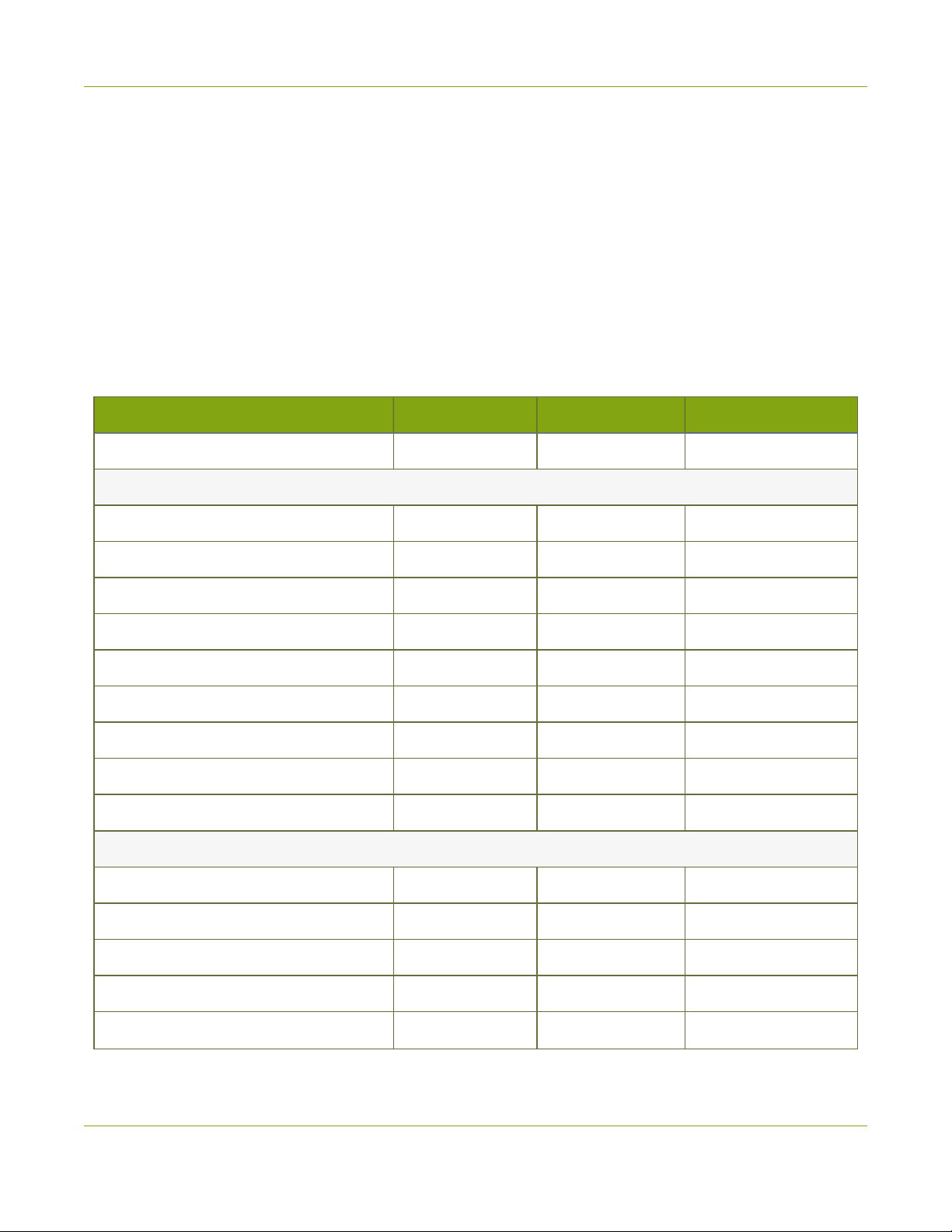
User Privileges
The following table outlines the privileges for each user:
Table 7 User Privileges in the Web Interface
Action or Menu Option viewer operator admin
View channel output
Channel Operations
View Channel Configuration
Configure Stream Channel
Publish a Stream
Configure Stream Branding
Start the Stream Recorder
Stop the Stream Recorder
View Recorded FilesList
Download RecordedFiles
Delete RecordedFiles
SystemConfiguration Operations
View System Configuration
ü ü ü
ü ü
ü
ü
ü
ü ü
ü ü
ü ü
ü ü
ü ü
ü ü
Configure Automatic File Upload
Select External USBDrive Behavior
Configure FTPServer
Configure UPnP Sharing
ü
ü
ü
ü
20
Page 30

VGADVI Broadcaster User Guide 1-2 User Administration
Action or Menu Option viewer operator admin
Configure Network Address
Configure USBTethering
Perform NetworkDiagnostics
Configure Date andTime preferences
Set or Change User Passwords
Configure SerialPort Flow Control
Upload Branding Images
Upload Branding Templates
Select BrandingTemplate
Enable Remote Support
Backup Device Configuration
Restore DeviceConfiguration
RestoreFactoryConfiguration
ü
ü
ü ü
ü
ü
ü
ü
ü
ü
ü
ü
ü
ü
Reboot Device (via Web Interface)
Configure Time Until Next DiskCheck
Perform DiskCheck
View DiskInformation
Upgrade Firmware
View System Information
ü ü
ü ü
ü
ü
ü
ü
Setting and Changing User Passwords
The VGADVI Broadcaster's three static users are: admin, operator and viewer.
None of the accounts have passwords assigned by default, but since both the admin and the operator user
have access to the web admin interface, you should always have a password for both admin and operator
accounts. Refer to your system administrator for your organization’s specific password requirements.
21
Page 31

VGADVI Broadcaster User Guide 1-2 User Administration
Passwords are case sensitive and can use all alpha-numeric keys in the ASCII range. Your password can be up
to 255 characters long, but should not include any spaces.
Setting a user’s password causes the user to be logged out. Be ready to log back in with the new
admin password or have operators and viewers log in with the appropriate new password. Viewers
may need to refresh their browser window or press play in their media player.
If you lose the admin password, refer to the section Overcoming Lost Passwords.
To set a user password:
1. Connect to the admin interface using your preferred connection mechanism. See Connect to the Admin
Interface.
2. Login as admin.
3. Select the Access passwords link in the Configuration menu; the password configuration page opens.
4. Highlight and delete the current password for your selected user (the password is currently masked as
dots).
For security reasons, the current password appears as eight dots regardless of password
length, and even if there is no password set.
5. Highlight and delete the confirmation password for the selected user.
6. Select the user’s password field and type a new password for the user.
The new password must have between 1-255 alpha-numeric characters or special characters
with no spaces. Passwords are case sensitive.
7. Select the user’s password confirmation field and confirm the new password.
8. Click Apply.
9. If you were logged in as the user whose password you just changed, you are logged out and must log
back in with the new password. If you added or changed the viewer’s password, all viewer’s stream will
pause until they log in with the new password.
If desired, you may specify multiple account passwords on the same page before clicking Apply.
Removing User Passwords
If you want to remove passwords for one or more user accounts, you may do so via the web interface. If you
don’t remember the admin password, refer to the section Overcoming Lost Passwords.
22
Page 32

VGADVI Broadcaster User Guide 1-2 User Administration
Clearing a user’s password will cause that user to be logged out. Be ready to log back in with the
new admin password. If viewers are watching the broadcast when the viewer password is cleared
they will be logged out. Viewers may need to refresh their browser window or press play in their
media player to trigger the login prompt.
To clear a user’s password:
1. Connect to the admin interface using your preferred connection mechanism. See Connect to the Admin
Interface.
2. Login as admin.
3. Select the Access passwords link in the Configuration menu; the password configuration page opens.
4. Highlight and delete the current password for your selected user (the password is currently masked as
dots).
For security purposes, the current password appears as eight dots regardless of password
length, and even if there is no password set.
5. Highlight and delete the confirmation password for the selected user.
6. Click Apply.
7. If you were logged in as the user whose password you just cleared, you are logged out and must log
back in without a password. If you cleared the viewer’s password, all viewers’ stream will pause until they
log in without a password.
Overcoming Lost Passwords
If you have lost the password for the operator or viewer account, you can log in to the web interface as admin
and reset the password using the procedure described in Setting and Changing User Passwords.
If you have lost the admin password you will need to reset the device to factory defaults, which resets to the
default blank admin password. See Restoring Factory Configuration.
After resetting to factory defaults, you can restore a configuration file with your known good configuration.
Remember to set user passwords after loading a configuration. Passwords are not saved in the configuration
file. See Save and Restore Device Configuration.
Changing the logged-in user
When you log in to the web interface as admin or operator, your browser remembers this configuration and
automatically logs you in as the same user when you go back to the site.
23
Page 33

VGADVI Broadcaster User Guide 1-2 User Administration
Sometimes you need to change from operator to admin, or vice versa.
To change the logged-in user:
1. Exit your browser completely, or open a different browser (i.e. Internet Explorer, Chrome, and Safari are
different browsers).
2. Connect to the admin interface using your preferred connection mechanism. See Connect to the Admin
Interface.
3. You are prompted for a username and password.
24
Page 34

VGADVI Broadcaster User Guide 1-3 Configure Network Settings
1-3
By default the VGADVI Broadcaster uses DHCP to obtain an IP Address via an Ethernet-based network. If you
want to change the network settings, or if you’re having network-related issues, this section covers the
following related topics:
Configure Network Settings
l Verify IP Address and MAC address
l Configure a Static IP Address
l Configure DHCP
l Tether to a Mobile Network
l Perform Network Diagnostics
Verify IP Address and MAC address
The web interface shows you the device’s MAC address and current IP Address via the Network configuration
page.
To view settings on network configuration page:
1. Connect to the admin interface using your preferred connection mechanism. See Connect to the Admin
Interface.
2. Login as admin.
3. Select the Network link in the Configuration menu; the network configuration page opens.
4. Note the MAC address and Current IP address listed at the top of the page.
Table 8 Network InformationFields
Label Description/Options
MACAddress A media access control address (MAC address) is a unique identifier for the
network interface. The value is read-only and cannot be changed. You may need
to share this value with your system administrator.
25
Page 35

VGADVI Broadcaster User Guide 1-3 Configure Network Settings
Label Description/Options
Current IPAddress Reflects the current internet protocol address (IP address) of the system. This
value is either obtained from the DHCP server (if using DHCP) or is the configured
static IP address. The VGADVI Broadcaster supports IPv4 addresses. It does not
support IPv6 addresses.
Configure a Static IP Address
Your network administrator may require you to use a static IP address for your VGADVI Broadcaster Pro.
To configure a static IP address:
1. Connect to the admin interface using your preferred connection mechanism. See Connect to the Admin
Interface.
2. Login as admin.
3. Select the Network link in the Configuration menu; the network configuration page opens.
4. Select the radio button use static address, if not already selected.
5. Enter the desired IP Address and Network Mask.
Only IPv4 addresses are supported.
6. Enter the Default Gateway address. If you do not have a default gateway for your network, enter the
new static IP address of the VGADVI Broadcaster.
26
Page 36

VGADVI Broadcaster User Guide 1-3 Configure Network Settings
The default gateway cannot be left blank. If no default gateway is specified, unexpected
behavior occurs.
7. Enter the DNS Server address. If you do not have a DNS server, enter the new static IP address of the
device.
The DNSServer address cannot be left blank. If no DNSServer is specified, unexpected behavior
occurs.
8. Change the MTU Size value only if needed. See the table below for information on maximum
transmission unit (MTU) values.
9. Click Apply to save the changes; the changes are saved and a message appears asking you to reboot.
10. Select the Maintenance link under the Configuration menu; the maintenance page appears.
11. Click the Reboot Now button near the bottom of the page.
12. Wait for the system to reboot.
13. Open the Web interface using the new IP address.
14. Log as admin and reload the Networking page to verify all changes were applied.
The following table describes applicable fields when setting a static IP address.
Table 9 Static IPAddress Fields
Label Description/Options
Use DHCP Select this radio button to dynamically obtain an IP address at boot up.
Use static address Select this radio button to use the configured static IP address.
IP Address The internet protocol address (IP Address) to assign. This value is may be obtained
from your system administrator. The VGADVI Broadcaster supports IPv4 addresses. It
does not support IPv6 addresses.
Network Mask Also called the subnet mask, this value denotes a range of IP addresses. This value may
be obtained from your system administrator, determined from another computer on
the same subnet, or calculated using an online subnet calculator.
27
Page 37

VGADVI Broadcaster User Guide 1-3 Configure Network Settings
Label Description/Options
Default Gateway The network node that serves as an access point to the rest of the network. This value
cannot be blank. Specify the system’s IP address if you don’t have a default gateway on
your network.
DNS Server The domain name system server (DNS server) translates human-readable hostnames
into corresponding IP addresses. Specify the system’s IP address if you don’t have a
DNSserver on your network.
MTU Size The maximum transmission unit (MTU) specifies the maximum packet size for transfer
on the network. The default value is 1500, which is the largest value allowed by
Ethernet at the network layer. It’s best if all nodes in your network use the same value,
so only change this value if you know other nodes use a different value.
Configure DHCP
Occasionally, such as when moving your system to a new network, your VGADVI Broadcaster must switch from
static IP address allocation to dynamic allocation via DHCP. You can accomplish this three ways:
l Use the factory reset button to clear all your settings. See Restoring Factory Configuration.
l Load a configuration file that uses DHCP networking. See Load a saved device configuration.
l Changing the network settings. See the procedure below.
To configure use of DHCP for networking:
1. Connect to the admin interface using your preferred connection mechanism. See Connect to the Admin
Interface.
2. Login as admin.
3. Select the Network link in the Configuration menu; the network configuration page opens.
4. Select the radio button use DHCP, if not already selected.
5. Change the MTU Size value only if needed. See the table below for information on maximum
transmission unit (MTU) values.
6. Click Apply to save the changes; the changes are saved and a message appears asking you to reboot.
28
Page 38

VGADVI Broadcaster User Guide 1-3 Configure Network Settings
7. Select the Maintenance link under the Configuration menu; the maintenance page appears.
8. Click the Reboot Now button near the bottom of the page.
9. Wait for the system to reboot.
10. Connect to the admin interface using your preferred connection mechanism. See Connect to the Admin
Interface.
11. Log as admin and reload the Networking page to verify all changes were applied.
The following table describes the fields applicable when configuring DHCP on the VGADVI Broadcaster.
Table 10 DHCP Fields
Label Description/Options
Use DHCP Select this radio button to dynamically obtain an IP address at boot up.
Use static
address
MTU Size The maximum transmission unit (MTU) specifies the maximum packet size for transfer on
Use static address Select this radio button to use the configured static IP address.
the network. The default value is 1500, which is the largest value allowed by Ethernet at the
network layer. It’s best if all nodes in your network use the same value, so only change this
value if you know other nodes use a different value.
Tether to a Mobile Network
The VGADVI Broadcaster supports tethering to a mobile device via USB. This can work side-by-side with
Ethernet routing where one can be a back-up system for the other.
When the system falls over to the backup network type (i.e. from Ethernet to mobile, or vice versa)
all streaming sessions are closed and the clients will need to reconnect. You may need to provide a
new stream URL(containing the new IPaddress) to your viewers. See the channel information page
to get the new stream URL.
All actively published streams are closed and reconnected via the mobile network automatically
(assuming the required publishing server is accessible from the mobile network).
To configure tethering to a mobile network:
1. Configure the mobile device to allow tethering via USB.
2. Connect the mobile device to the VGADVI Broadcaster with a USB cable.
3. Connect to the admin interface using your preferred connection mechanism. See Connect to the Admin
Interface.
29
Page 39

VGADVI Broadcaster User Guide 1-3 Configure Network Settings
4. Login as admin.
5. Select the Network link in the Configuration menu; the network configuration page opens.
6. Click the dropdown box next to Use phone/tablet connection in the USB phone/tablet section; the
following choices appear:
Table 11 Mobile Tethering Options
Label Description/Options
Disabled Specifies that no USB tethering is permitted.
No tethering Specifies that USB tethering is available for connecting a mobile device as a
configuration utility (i.e use the web browser), but no mobile data is used.
Prefer ethernet When chosen, the system tries to use the Ethernet network first. It switches to use
the mobile network (tethering) when the Ethernet network is no longer available.
To prevent viewer interruptions, mobile data will continue to be used until the
mobile network is down or publishing is restarted.
Prefer
tethering
7. Select your choice based on the table above.
8. Click Apply.
When chosen, the system tries to use the mobile network (tethering) first. It
switches to use the Ethernet (hard-wired) when the mobile network is no longer
available. To prevent viewer interruptions, Ethernet data will continue to be used
until the Ethernet network is down or publishing is restarted.
Select this setting if you only have a mobile network.
Perform Network Diagnostics
If your VGADVI Broadcaster has network trouble, you can perform basic network troubleshooting tasks from
the Network configuration page. In addition to providing the device’s IP address and MAC address to your
network administrator (See Verify IP Address and MAC address), you can also ping an IP address or use
traceroute to determine the path taken to an address.
Note: Not all networks support ping and traceroute.
To ping or traceroute an IP address:
1. Connect to the admin interface using your preferred connection mechanism. See Connect to the Admin
Interface.
2. Login as admin.
3. Select the Network link in the Configuration menu; the network configuration page opens.
30
Page 40

VGADVI Broadcaster User Guide 1-3 Configure Network Settings
4. Click ping or traceroute; an animation appears to the left of the address to indicate processing is
underway.
5. Upon completion of the command, read the results from the console-like display is shown below the
Network Diagnostics setting.
31
Page 41

VGADVI Broadcaster User Guide 1-4 Configure Date and Time
1-4
The VGADVI Broadcaster uses the current date and time in naming recorded files and when synchronizing and
timestamping inputs from multiple sources (i.e. when synchronizing an audio and a video source). The admin
interface lets you specify date and time settings to ensure they are correctly configured for your time zone and
your network. This section covers the following date and time-related topics:
Configure Date and Time
l Verify Date and Time Settings
l Change the Time Zone
l Configure Synchronized Time (NTP, PTP v1, and RDATE)
l Manually Configure the Date and Time
Verify Date and Time Settings
The current date, time, time zone, and synchronized time protocol settings are shown when the Date and Time
configuration page is loaded in the VGADVI Broadcaster web interface.
To view settings on date and time configuration page:
1. Connect to the admin interface using your preferred connection mechanism. See Connect to the Admin
Interface.
2. Login as admin.
3. Select the Date and Time link in the Configuration menu; the date and time configuration page opens
and the following information is displayed:
32
Page 42

VGADVI Broadcaster User Guide 1-4 Configure Date and Time
The date and time configuration page also indicates whether the device is currently using synchronized or
manually set time, and whether or not a local network time protocol (ntp) server is running.
The following table describes the date and time configuration fields.
Table 12 Date and Time Options
Label Description/Options
Time Zone The currently selected time zone.
Enable time
synchronization
Protocol The time synchronization protocol.
ServiceIPAddress The time synchronization server address.
Set time manually Whether or not time is set manually. (If time is not being set manually, a time
Whether or not a time synchronization protocol is being used for setting time. (If not
selected, time is set manually.)
synchronization protocol is used.)
33
Page 43

VGADVI Broadcaster User Guide 1-4 Configure Date and Time
Label Description/Options
Date The current date. (This is the current date even if the radio button Set time manually is
not selected.)
Time The current time. (This is the current time even if the radio button Set time manually is
not selected.)
Change the Time Zone
By default the device has the Canada/Eastern time zone set. Configuration of the time zone is necessary to
ensure synchronized time servers provide the correct time to the device.
To select another time zone:
1. Connect to the admin interface using your preferred connection mechanism. See Connect to the Admin
Interface.
2. Login as admin.
3. Select the Date and Time link in the Configuration menu; the date and time configuration page opens.
4. Select the new time zone from the Time Zone drop down box.
5. Click Apply.
Configure Synchronized Time (NTP, PTP v1, and RDATE)
By default the VGADVI Broadcaster uses the network time protocol server (NTP server) protocol and the time
server from National Research Council Canada. You can continue to use this time server or configure a new
server that is more appropriate for your network and location. Your system administrator can provide the
correct time synchronization server settings.
To set the time synchronization method:
1. Connect to the admin interface using your preferred connection mechanism. See Connect to the Admin
Interface.
2. Login as admin.
3. Select the Date and Time link in the Configuration menu; the date and time configuration page opens.
4. Click the Enable time synchronization radio button if it is not already selected.
5. Choose one of the following choices from the Protocols drop down:
34
Page 44

VGADVI Broadcaster User Guide 1-4 Configure Date and Time
Table 13 Synchronized Time Options
Label Description/Options
NTP Network Time Protocol (NTP) is used for clock synchronization over the internet.
There are many publicly available NTP servers you can use, or your company may
have its own NTP server. For more information about NTP and to find NTPservers,
refer to http://support.ntp.org/bin/view/Servers/WebHome.
RDATE RDATE is a tool for querying the current time from the network. It is generally
considered obsolete and has been replaced by NTP.
PTP v1 The Precision Time Protocol (PTP) is used for clock synchronization over the
internet. It has clock accuracy in the sub-microsecond range, making it more
granular than NTP.
6. Tailor the synchronization protocol with the required parameters as described below.
7. If NTP is selected:
a. Enter the IP address or server name for the NTP server in the Server IP Address field.
NTP uses UDP packets and port 123. If the device is behind a firewall and accessing an
external NTP server, UDP packets must be permitted on port 123.
8. If RDATE is selected:
a. Enter the IP address or server name for the RDATE server in the Server IP Address field.
b. Select an update interval from the drop down box.
9. If PTP v1 is selected:
a. Select the multicast address of PTP v1 server from the PTPdomain dropdown.
PTP Domain Description
Default PTPat multicast address 224.0.1.129
Alternative 1 PTPat multicast address 224.0.1.130
Alternative 2 PTPat multicast address 224.0.1.131
Alternative 3 PTPat multicast address 224.0.1.132
PTP uses UDP packets and ports 319 and 320 . If the device is behind a firewall and accessing
an external PTP server, UDP packets must be permitted on ports 319 and 320.
10. Click Apply.
35
Page 45

VGADVI Broadcaster User Guide 1-4 Configure Date and Time
Manually Configure the Date and Time
By default the VGADVI Broadcaster uses NTP for time synchronization. If your system does not have access to a
time synchronization server, or if you do not wish to use one, you can choose to manually set the date and
time.
To manually set the date and time:
1. Connect to the admin interface using your preferred connection mechanism. See Connect to the Admin
Interface.
2. Login as admin.
3. Select the Date and Time link in the Configuration menu; the date and time configuration page opens.
4. Type the desired date in the Date field. Use the format yyyy-mm-dd.
5. Type the desired time in the Time field. Use the format hh:mm:ss.
6. Click Apply.
36
Page 46

VGADVI Broadcaster User Guide 1-5 Restrict Viewers by IPAddress
1-5
The VGADVI Broadcaster permits you to restrict which computers can access broadcasts by building a list of
allowed and/or denied IP addresses.
If your viewer account has a password, your viewers must connect to the device from a computer (or gateway)
with a permitted IP address and must also supply the username and password before they can view the
broadcast.
To restrict access by IP address you need to know the IP addresses, or range of addresses for your viewers. By
default all IP addresses are allowed to connect to the broadcast.
If you’re not familiar with creating allow/deny lists, refer to the examples below this procedure for assistance
with crafting your lists.
Restrict Viewers by IPAddress
IP address restriction is valid for the viewer only and does not affect the web interface or the
mobile configuration interface.
IP Address restriction is not configurable per channel. Restrictions affect all broadcasts / streams
from the device.
To restrict viewers by IP address:
1. Connect to the admin interface using your preferred connection mechanism. See Connect to the Admin
Interface.
2. Login as admin.
3. Select the Access passwords link in the Configuration menu; the password configuration page opens.
4. Type allowed IP addresses or address ranges in the Allow IP’s field. Separate addresses with a comma.
5. Type denied IP addresses or address ranges in the Deny IP’s field. Separate addresses with a comma.
6. Click Apply.
If a user attempts to connect to the stream from a disallowed IPaddress, access is denied. If connecting by
internet browser, the message "IPaddress rejected." is displayed.
The following table describes the applicable fields.
37
Page 47

VGADVI Broadcaster User Guide 1-5 Restrict Viewers by IPAddress
Table 14 IP Based Restriction Fields
Label Description/Options
Allow IP's Enter individual IP Addresses or IP Address ranges, separated by commas. To specify a
range, use a hyphen (-). Optional spaces improve readability.
Users connecting from addresses in this list are permitted to view broadcasts from the
device, provided their IP address is not in the Deny IP’s list.
To allow all (except IP addresses in the deny list, if any), leave the field blank.
You can use the Allow list by itself, or in conjunction with the Deny IP’s list as an exception
to a rule in the allow list.
Deny IP's Enter individual IP Addresses or IP Address ranges, separated by commas. To specify a
range, use a hyphen (-). Optional spaces improve readability.
Users connecting from addresses in this list are not allowed to view broadcasts from the
device, unless their IP address is in the Allow IP’s list. If a specific IP address is in both lists,
access to the stream is denied.
You can use the Deny list by itself, or in conjunction with the Allow IP’s list as an exception
to a rule in the allow list.
Examples
Allow List with Distinct IP Addresses
The simplest allow/deny list is to use the list of known IP addresses to craft a list of allowed IP addresses. All
other addresses are denied access to the broadcast.
For example if your device is accessible on your local area network (LAN) and you want to make sure only the
CEO’s specific desktop, laptop and tablet computers (with IP Addresses 192.168.1.50, 192.168.1.51, and
192.165.1.75, respectively) can connect to the broadcast, construct the following allow list:
Allow: 192.168.1.50, 192.168.1.51, 192.168.1.75
Allow List with a Range of IP Addresses
Sometimes you’ll want a range of computer IP addresses to connect to your device. This may happen when you
have one range of IP addresses assigned to desktop computers (i.e. in the range 192.168.1.1 to 192.168.1.100)
and another range assigned to boardroom computers (i.e. the range 192.168.1.200 to 192.168.1.250). If you
only want the boardroom computers to connect to broadcasts from the device you can specify the range of
boardroom IP addresses rather than needing to type in each individual address. The allow list looks as follows:
38
Page 48

VGADVI Broadcaster User Guide 1-5 Restrict Viewers by IPAddress
Allow: 192.168.1.200-192.168.1.250
Note that we could have specified two of the IP addresses in the previous example as a range.
Allow List with a Range of IP Addresses and One or More Specific IP
Addresses
Putting the first two examples together, we want to permit access to IP addresses in the range of boardroom
computers (192.168.1.200-192.168.1.250) and also want to add the desktop, laptop and tablet computers of the
CEO (IP addresses 192.168.1.50, 192.168.1.51, and 192.168.1.75, respectively). Note the first two IP addresses are
consecutive, so they can be added as a second range. Add these IP addresses to the list as follows:
Allow: 192.168.1.200-192.168.1.250, 192.168.1.50-192.168.1.51, 192.168.1.75
Your list can have multiple ranges and multiple distinct IP addresses, provided they are separated by commas.
Deny List with Distinct IP Addresses
Another simple allow/deny list is to use the list of known IP addresses to list specific denied IP addresses. All
other addresses are allowed access to the broadcast.
For example imagine your device is accessible on your local area network (LAN) and you want to allow any
computer on the LAN can access the stream except your publicly-accessible boardroom (with IP address
192.168.1.211). You can use the following deny list (leave the allow list empty) to permit all computers except
the boardroom computer:
Deny: 192.168.1.211
As with Allow lists, your deny list can specify a range of IP addresses, and can specify multiple ranges or distinct
IP addresses in a comma-separated list.
Allow List with a Range of IP Addresses, Distinct IP Addresses, and an
Exception
Building on the previous examples, consider the situation where you want the CEO’s computers (192.168.1.50,
192.168.1.51, 192.168.75) and all boardroom computers (192.168.1.200-192.168.1.250) to access the broadcast,
with the exception of the public boardroom computer (192.168.1.211). Use both allow and deny lists to create
the rule as follows:
39
Page 49

VGADVI Broadcaster User Guide 1-5 Restrict Viewers by IPAddress
Allow: 192.168.1.200-192.168.1.250, 192.168.1.50-192.168.1.51, 192.168.1.75
Deny: 192.168.1.211
Both lists can have multiple ranges and multiple distinct IP addresses, provided they are separated by commas.
Deny List with a Range of IP Addresses
Converse to the previous examples, consider the situation where you want every computer on the network to
access the broadcast, with the exception of the CEO’s desktop, laptop, and tablet computers. Additionally,
boardroom computers should not be permitted with the exception of the cafeteria computer (IP address
192.168.1.222).
The deny list is an "exception" list for the allow list. So to craft the rule described above we need to allow all the
computers in the local subnet, then deny specific sub-ranges including two groups of boardroom computers
ensuring the cafeteria computer's IP address is not in the deny list:
Allow: 192.168.1.1-192.168.1.250
Deny: 192.168.1.200-192.168.1.221, 192.168.1.223-192.168.1.250, 192.168.1.50-192.168.1.51, 192.168.1.75
40
Page 50

VGADVI Broadcaster User Guide PART 2: Sources
PART 2: Sources
Now that you know how to connect to the admin interface, you are ready to configure your input sources. The
following sections provide an overview of the types of sources you can connect to your VGADVI Broadcaster
and how to configure each source.
The following topics are covered:
l Identify sources
l Configure a video source
l Configure an audio source
l Fine-tune source configuration
41
Page 51

VGADVI Broadcaster User Guide 2-1 Identify sources
2-1
A source can be an image, video, or audio from a camera, a computer screen or any device that provides a VGA,
DVI, HDMI, S-Video and audio signal output. Prior to powering up the VGADVI Broadcaster connect the input
sources to the following input ports on the device:
Table 15 Cable and port connections
The web interface automatically discovers all input sources and displays them in the Stream Setup section of
the web admin interface.
When a source is connected, the system automatically detects and adjusts the image capture settings at start
up and continues to adjust every 60 seconds during operation (interval is configurable). The system’s goal is to
produce the best quality captured image given the source equipment used. Generally no further configuration
is needed.
Identify sources
Cable Input Port
connect VGA, HDMI or DVl (dual or single link,
depending on your device)
connect composite or S-video source S-Video port
connect audio Audio Input port
DVI port
42
Page 52

VGADVI Broadcaster User Guide 2-2 Configure a video source
2-2
To configure a source:
Configure a video source
The following adjustments cannot be made for S-Video sources.
1. Connect to the admin interface using your preferred connection mechanism. See Connect to the Admin
Interface.
2. Login as admin.
3. Ensure a source is connected to the input port, see Table Configure a video source.
4. From the web interface, click Frame Grabber from the Configuration menu; the Frame Grabber
Adjustments page opens.
5. Make fine adjustments if required, however in most cases the video is ready to view from a channel and
ready to stream.
Value Description
Use signal from Specify the native color space of the signal source, either RGB or YUV. The
following values are available:
l VGA/DVI signal (RGB) (this is the default setting)
l Component signal (YCrCb)
Interval between
VGA signal and
autoadjustments
(sec)
Vertical shift When an image is not aligned in the window, use this feature to move an image
Horizontal shift When an image is not aligned in the window, use this feature to move an image
Phase Specifies phase adjustments for VGAsignals. Generally not used unless value is
When a source is setup, the system automatically detects and adjusts the image
capture settings at start up and continues to adjust every 60 seconds during
operation. To change the number of seconds between update, enter a value, or
0 to disable the feature, otherwise the default of 60 seconds is set.
up or down on the screen. The values range from 20 (moves the image up) to –
20 (moves the image down).
left or right on the screen. The values range from -999 (moves the image to the
left) to 999 (moves the image to the right).
provided by Epiphan support.
43
Page 53

VGADVI Broadcaster User Guide 2-2 Configure a video source
Value Description
PLL adjustment Changing the value adjusts the horizontal resolution of the image. Adjust the
value using small increments until the image is sharper. The value ranges from 0999 to 999.
Offset The Offset and Gain parameters function as contrast control for an image. The
Offset controls the darker parts of the image and the gain controls the bright
parts of the image. Adjust both values to optimize image quality. Adjust the
values using small increments until the image is sharper. If you set Offset to a
high value, set a high value for the gain to balance the two.
Gain The Gain and Offset parameters function as contrast control for an image. The
Gain controls the bright parts of the image and Offset controls the darker parts
of the image. Adjust both values to optimize image quality. Adjust the values
using small increments until the image is sharper. If you set Offset to a high
value, set a high value for the Gain to balance the two.
Aspect Ratio Sets the aspect ratio of the captured image. The default is 4:3. Set the value to
Wide mode when capturing images that have a wide aspect ratio. Using the
incorrect setting causes the image to be distorted or stretched.
HSync threshold Adjust horizontal sync detection.
VSync threshold Adjust vertical sync detection.
44
Page 54

VGADVI Broadcaster User Guide 2-3 Configure an audio source
2-3
The VGADVI Broadcaster web interface automatically discovers all input sources and displays them in the
Stream Setup section of the web interface. Audio input devices such as a microphone and portable music
players can send audio signals to the VGADVI Broadcasterusing the audio input port.
Use the following sections to configure the audio settings that control the audio input:
Add an audio source to a channel
Configure audio settings
Set audio volume
View audio signal strength
Configure an audio source
All available video formats support audio except Motion JPEG.
Add an audio source to a channel
To add an audio source to a channel:
1. Ensure an audio input source is connected to the device.
2. Connect to the admin interface using your preferred connection mechanism. See Connect to the Admin
Interface.
3. Login as admin.
4. From the web interface, click Stream Setup; the Stream setup page opens.
5. Scroll to the Audio Settings section.
6. Click Enable audio.
7. Click Apply.
8. To select an audio codec for an audio stream, see Fine-tune channel configuration.
Configure audio settings
To configure audio settings:
1. Connect to the admin interface using your preferred connection mechanism. See Connect to the Admin
Interface.
2. Login as admin.
45
Page 55

VGADVI Broadcaster User Guide 2-3 Configure an audio source
3. From the web interface, scroll to the channel section and click the channel to which you want to
configure audio settings; the menu expands.
4. Click Stream Setup; the Stream setup configuration page opens.
5. Scroll to Audio settings.
6. Check Enable audio check box.
7. If the default audio format (PCM 22KHz) is not desired, click the Audio format drop-down menu to elect
an audio codec. See Fine-tune channel configuration for help choosing one of the supported audio
codecs.
8. Click on the Audio channels drop-down menu to choose mono (1 channel) or stereo (2 channels).
9. Click on the Audio bitrate drop-down menu to choose the audio transmission speed. Increasing this
value produces better sound quality but uses more system processing power and bandwidth.
10. Click Apply.
Set audio volume
To set audio volume (not this is done on the encoder, and not the VGAGrid):
1. Ensure an audio input source is connected to an audio input port.
2. Connect to the admin interface using your preferred connection method. See Connect to the Admin
Interface.
3. Login as admin.
46
Page 56

VGADVI Broadcaster User Guide 2-3 Configure an audio source
4. From the web interface, scroll to the Configuration section.
5. Click Audio; the following window opens.
6. Select the Input source from the drop-down menu. Choose Line (default setting), to capture system
audio, or choose Mic to capture audio from a microphone connected to the audio input port.
7. Click on the Input Amplifier volume drop-down menu. A list of percentages is displayed. Choose to
amplify the volume by a percentage of the original volume. The default setting is 30%. Decrease the
percentage if the output volume is too loud. Increase the percentage if the output volume is not loud
enough.
Adjusting the Input Amplifier volume adjusts the output audio as well.
8. Enable Microphone 20dB boost to provide additional amplification for the microphone inputs.
9. Click Apply.
View audio signal strength
An audio meter indicates the signal strength of an audio source. If the signal is weak you may experience
volume quality issues. You can adjust the output volume on the audio source and/or adjust the capture
volume, see Set audio volume.
To view audio signal strength when an audio source is connected to the device:
1. Ensure an audio input source is connected to an audio input port.
2. Connect to the admin interface using your preferred connection method. See Connect to the Admin
Interface.
3. Login as admin or operator.
4. From the web interface, click Info menu option.
47
Page 57

VGADVI Broadcaster User Guide 2-3 Configure an audio source
5. Scroll to the Input section. The Audio meter is displayed.
6. View the strength of the audio signal. The following example shows an audio input with a strong signal.
48
Page 58

VGADVI Broadcaster User Guide 2-4 Fine-tune source configuration
2-4
In addition to fine tuning channel settings such as frame rate, resolution and bit rate to ensure optimal use of
resources while streaming a quality video, there may be circumstance when you must fine tune the video input
source.
Fine-tune source configuration
Changing how source images are displayed may cause undesired results, for example
experimenting with the PLLsetting may result in the image not being displayed properly. It is a
good practice to backup your configuration settings so that you can revert back to a good
configuration if the changes that you made are not desirable. See Save and Restore Device
Configuration .
Video is not centered on the screen
The image from the source is displayed too high or low, or too far to the left or right.
1. Connect to the admin interface using your preferred connection mechanism. See Connect to the Admin
Interface.
2. Login as admin.
3. From the web interface, click Frame Grabber from the Configuration menu; the Frame Grabber
Adjustments page opens.
4. To move the video horizontally to the left or right, scroll to Horizontal shift .
5. Enter incremental values to shift the video image to the left (use a negative value) or right (use a positive
value).
6. Click Apply. View the output by clicking on the Snapshot link in the Info window. You may need to make
further adjustments to move the video left or right.
49
Page 59

VGADVI Broadcaster User Guide 2-4 Fine-tune source configuration
7. Click Apply after each change to confirm the results.
8. To move the video up or down, scroll to Vertical shift .
9. Enter incremental values to shift the video image down (use a negative value) or up (use a positive
value).
10. Click Apply.View the output by clicking on the Snapshot link in the Info window. You may need to make
further adjustments to move the video up or down.
Video is too bright, too dark or washed out
If the video from the source is too light, too dark or washed out, use the offset and gain controls together to
optimize image quality. Increasing the gain amplifies weak signals but also increases noise, you must balance
offset and gain values to achieve the best quality image.
Adjust these settings by the smallest values possible; compensate for a large change to one by making a large
change to the other. Setting both offset and gain to high values can result in poor video quality.
1. Connect to the admin interface using your preferred connection mechanism. See Connect to the Admin
Interface.
2. Login as admin.
3. From the web interface, click Frame Grabber from the Configuration menu; the Frame Grabber
Adjustments page opens.
4. Scroll to Gain.
5. Enter a small value, for example 1 to 25 in the field to brighten the image.
6. Scroll to Offset.
7. Enter a small value, for example 1 to 15 , to balance the gain setting . The Offset value behaves as a
contrast to the Gain value.
50
Page 60

VGADVI Broadcaster User Guide 2-4 Fine-tune source configuration
8. Click Apply. View the output by clicking on the Snapshot link in the Info window. You may need to make
further adjustments to fine tune the brightness and contrast.
Video looks squished
The image is squeezed horizontally on the screen. This distortion occurs when there's a mismatch between the
aspect ratio the VGADVI Broadcaster detects and the aspect ratio that is sent from the source signal. To
compare the two signal values, you must know the aspect ratio that the source is sending.
1. Connect to the admin interface using your preferred connection mechanism. See Connect to the Admin
Interface.
2. Login as admin.
3. From the web interface, click Info; the info window opens.
4. Compare the aspect ratio from the source with the aspect ratio from theVGADVI Broadcaster info
window. Confirm if there is a mismatch.
5. If there is a mismatch, go to the stream setup for the channel and change the frame size to match the
frame size that is sent from the source. See Configure channels.
6. If the video is still squeezed horizontally on the screen, follow the steps below.
7. From the web interface, click Frame Grabber from the Configuration menu; the Frame Grabber
Adjustments page opens.
8. Scroll to the Aspect ratio setting.
9. Select Wide mode from the drop-down menu, when the source is wider than what is being displayed in
the preview or Live View.
10. Click Apply. View the output by clicking on the Snapshot link in the Info window.
51
Page 61

VGADVI Broadcaster User Guide 2-4 Fine-tune source configuration
Remove the combing effect on images
When frames are interlaced, artifacts from one frame may appear on the next frame. This occurs when a fast
motion video is interlaced. Since each frame is captured from a different point in time, the action captured in
one frame is carried over to the next frame. The result is a blurred image and horizontal lines running across
the video.
To convert an interlaced source signal to a non-interlaced signal.
1. Connect to the admin interface using your preferred connection mechanism. See Connect to the Admin
Interface.
2. Login as admin.
3. From the web interface, click Frame Grabber from the Configuration menu; the Frame Grabber
Adjustments page opens.
4. Enable the Enable deinterlace setting.
5. Click Apply. View the output by clicking on the Snapshot link in the Info window.
Force the video source to use a specific resolution
Extended display identification data (EDID) is data provided by a video display device (usually a monitor) to
describe its capabilities to a video source. The video source uses the EDID to determine the capabilities of the
monitor to determine the resolution, color depth and other settings that the monitor can support. EDID is
crucial for DVI sources but mostly ignored by VGA sources.
When you connect the VGADVI to a video source, the video source sees the device as a monitor. Just like a
monitor, the VGADVI contains the EDID that is used by the video source to determine the video signal to send.
Upload a new EDID
In most circumstances the factory installed default EDID, is sufficient. However, there may be some cases where
a video source uses resolutions that you do not want to use. In that case you can choose an EDID that forces
the video source to use a specific resolution.
The uploaded EDID is permanently installed on your VGADVI and will always share this EDIDwith the video
input source.
1. Connect to the admin interface using your preferred connection mechanism. See Connect to the Admin
Interface.
2. Login as admin.
52
Page 62

VGADVI Broadcaster User Guide 2-4 Fine-tune source configuration
3. To download a new EDID file, go to Epiphan Downloads. The downloads page opens.
4. Click EDID; a page displaying a list of EDIDs opens.
5. Click on an EDIDfrom the list. The file is saved to your downloads folder on your C: drive.
6. From the web interface, click Frame Grabber from the Configuration menu; the Frame Grabber
Adjustments page opens.
7. Scroll to EDID upload.
8. Click Choose File. A browser page opens.
9. Browse to the location where the custom EDID file was saved and select the file.
10. Click open. The EDID is uploaded. An information dialog box appears.
11. Click OK. The browser window closes.
53
Page 63

VGADVI Broadcaster User Guide PART 3: Channels
PART 3: Channels
Channels organize and display content captured from DVI, VGA, HDMI, audio and camera input sources. A
channel can be set up to display the content from one input source, or may capture, stream and record
content from two input sources. You can identify your channel by adding a corporate logo, company
information, corporate color and time stamps.
Through channel configuration and fine tuning you can maximize your stream quality, minimize your
processing requirements and bandwidth and specify how the video is presented and streamed to a sharing
destination/viewer.
This section discusses the following topics related to channel configuration:
l Configure channels
l Fine-tune channel configuration
l Customize your channel
54
Page 64

VGADVI Broadcaster User Guide 3-1 Configure channels
3-1
Channels make your sources available for viewing and recording.You choose how you want to configure the
sources to make a channel.
This section covers the following topics for creating channels:
While configuring a channel, consider opening a live preview of the channel in another tab or browser window
so you can see the changes as they are applied. Right-click Live View and select open in a new window or
open in a new tab to start the preview.
Configure channels
l Create a DVI channel
l Create a Video channel
l Enable and disable a channel
l Configure picture in picture or picture with picture layout
Create a DVI channel
A single source channel displays the output from one source in one viewing screen. Follow the steps below to
create a DVI channel. In this section you can choose settings that maximize your stream quality, while
minimizing your processing requirements and bandwidth by adjusting frame rate, resolution and bit rate.
Procedures to select a codec for compression, add a time stamp to the stream, and select a layout when two
sources are configured are described in separate procedures.
To add a DVI channel:
1. Connect to the admin interface using your preferred connection mechanism. See Connect to the Admin
Interface.
2. Login as admin.
3. Ensure a DVIinput source is connected to the device.
4. From the side menu, scroll to the Channels section.
5. Click Stream Setup; the Stream setup page opens.
55
Page 65

VGADVI Broadcaster User Guide 3-1 Configure channels
6. Scroll to the DVI Channel section.
7. Check the Enable DVI channel checkbox.
8. If you're not sure what Codec to pick, keep the default, H.264. For help selecting a codec, refer to Fine-
tune channel configuration
9. Keep the default video encoding preset and video encoding profile for help selecting these values,
refer to Fine-tune channel configuration
10. Perform one of the following steps:
a. Check the Use current signal resolution as the frame size check box. Typically you want to
broadcast at the same frame size as the source.
Enabling this feature greys out the fields to change the frame size. Changing the
input signal resolution may lead to interrupted streaming and recording. Enabling
this feature may not be suitable for systems where input resolution is changed
frequently.
b. Change the frame size, follow the steps below.
11. Set the Frame size to reflect the same dimensions as your source or as sharing destination. Default
values cover popular resolutions of cameras and display devices such as monitors or choose one of the
following:
a. Type a frame size in the field; or
b. Select an option from the sizes shown, the dimensions will appear in the frame size field.
To verify your frame size setting, click on the Live View menu option. The content is
displayed using the selected frame size
12. Check the Keep aspect ratio checkbox to preserve the source aspect ratio when scaling
56
Page 66

VGADVI Broadcaster User Guide 3-1 Configure channels
If you choose to keep the aspect ratio of the source and your selected output frame size
aspect ratio is wider than the source aspect ratio, bars will appear on the sides of the video.
If the frame size aspect ratio is taller than the source, bars will appear at the top and bottom
of the output. See Control the matte (black bars) in the video output.
13. Click on the Key frame interval drop-down box to choose how often a key frame (a frame that contains
all the pixels) is used when streaming the video. The longer the key frame interval the smaller the video
file size, and vice versa. The higher the value the faster a user moves through the frames of the video
when using the search function of their media player. For more information on adjusting this feature to
reduce bandwidth and system resources, see Fine-tune channel configuration .
14. Change the Limit frame rate. The default should be adequate in most applications. While decreasing
the limit may improve system performance, you may need to test different values to balance video
smoothness and processing power.
15. Increase or decrease image quality by increasing or decreasing the target Bitrate value when H.264 and
MPEG4 codecs are used. Video with a high level of motion and high resolution, such as a sporting event,
requires a high bitrate.
Raising this value uses more system processing power and bandwidth.
16. Set the Quality parameter when the Motion JPEG codec is used to increase or decrease image quality.
This feature has the same behavior as the Bitrate value used for H.264 and MPEG4 codecs.
17. To configure the Show time label, see Creating a time stamp in the Customize your channel
18. Click Apply.
Create a Video channel
Follow the steps below to create an S-Video channel. Procedures to select a codec for compressions and
decompression, add a time stamp to the stream, and select a layout when two channels are configured are
described in separate procedures.
To add a video channel:
1. Connect to the admin interface using your preferred connection mechanism. See Connect to the Admin
Interface.
2. Login as admin.
3. Ensure an S-Video input source is connected to the device.
4. From the web interface, click Stream Setup; the stream setup window opens.
57
Page 67

VGADVI Broadcaster User Guide 3-1 Configure channels
5. If you're not sure which codec to pick, keep the default, H.264. For help selecting a codec, refer to Fine-
tune channel configuration
6. Keep the default video encoding preset and profile, or for help selecting these values, refer to Fine-tune
channel configuration
7. Scroll to the Video Channel section.
8. Select the Enable video channel check box, if not already selected.
9. Perform one of the follow:
a. If a DVI and video source is configured, you can combine both sources into one channel. See
Configure picture in picture or picture with picture layout.
b. If a single source is configured for the channel go to the next step.
8. Specify the type of video signal coming from the S-Video source. The options are S-Video or Composite.
9. Perform one of the following:
a. Check the Use current signal resolution as the frame size check box. Typically you want to
broadcast at the same frame size as your monitor. Skip the next step.
Enabling this feature greys out the fields to change the frame size. Options for
an S-Video channel are based on SD camera resolutions, while DVI channels
have a wide range of frame size options.
58
Page 68

VGADVI Broadcaster User Guide 3-1 Configure channels
b. Change the frame size, follow the steps below.
10. Set the Frame size to reflect the same dimensions as your sharing destination. Default values cover
common sharing destinations such as websites or choose one of the following.
a. Type a frame size in the field; or
b. Select an option from the sizes shown, the dimensions will appear in the frame size field.
11. Check the Keep aspect ratio check box to preserve the aspect ratio when scaling a frame size.
If you choose to keep the aspect ratio of the source and your selected output frame size
aspect ratio is wider than the source aspect ratio, bars will appear on the sides of the video.
If the frame size aspect ratio is taller than the source, bars will appear at the top and bottom
of the output. See Control the matte (black bars) in the video output
12. Click on the Key frame interval drop-down box to choose how often a key frame (a frame that contains
all the pixels) is used when streaming the video. The longer the key frame interval the smaller the video
file size, and vice versa. The higher the value the faster a user moves through the frames of the video
when using the search function of their media player.
For multiple source channels the key frame interval is configured in the DVIsection.
13. Change the frame rate limit. The default should be adequate in most applications. While decreasing the
limit may improve system performance, you may need to test different values to balance smoothness
and processing power.
For multiple source channels frame rate is configured in the DVIsection.
14. Increase or decrease image quality by increasing or decreasing the Bitrate value when H.264 and MPEG4
codecs are used. The default bitrate is set to 4000 kbit/s.
Raising this value uses more system processing power and bandwidth.
For multiple source channels bitrate is configured in the DVIsection.
15. To configure the Show time label, see Add a time stamp to your channel
For multiple source channels timestamp is configured in the DVIsection.
16. Click Apply.
59
Page 69

VGADVI Broadcaster User Guide 3-1 Configure channels
Configure picture in picture or picture with picture layout
When your VGADVI Broadcaster has two attached video sources, you can create a layout for the
recording/broadcast and specify how each video is positioned on the screen. You can choose one of the
following layouts:
l A single stream that combines both video and DVI channels into a traditional picture in picture layout.
Both video source signals and an audio source signal are combined and recorded to one file containing
one video and one audio track.
l A single stream that combines both video and DVI channels a picture beside picture layout. Both video
source signals and an audio source signal are combined and recorded to one file containing one video
signal and one audio track.
l Independent streams for each of video and DVI. Each stream has a different URL. Video source signals
and the audio source signal are recorded as separate tracks in a multi-track file.
To create a picture in picture or picture with picture layout:
1. Connect to the admin interface using your preferred connection mechanism. See Connect to the Admin
Interface.
2. Login as admin.
3. Ensure two video input sources are connected to the device.
4. From the web interface, click Stream setup; the Stream setup page opens.
5. Scroll to the DVI channel section.
6. Check the Enable DVI channel check box.
7. Scroll to the Video channel section.
8. Check the Enable video channel check box.
Channel source layout is not available if Enable video channel is unchecked.
9. Select a Picture in Picture layout to specify how each input source (DVI or VGA and S-video) is streamed.
Hardware limits the position of the S-Video picture to align with a multiple of 32 pixels. As a
result, it's possible there is a small gap between the DVI/VGAand S-Video streams, or that the
S-Video stream is not perfectly right-aligned when superimposed over the DVI/VGA stream.
60
Page 70

VGADVI Broadcaster User Guide 3-1 Configure channels
10. Click the Video signal type drop-down menu to specify if the video signal from the input source is
composite or S-video.
11. To choose a background color or to add a brand to your streaming video, see Customize your channel.
12. To set the frame size of the streaming video, see Upscale or downscale your video image
13. To add a timestamp to your streaming video, see Add a time stamp to your channel.
14. Click Apply.
To create independent streams (picture beside picture), follow the steps below.
When independent streams are published, audio is streamed with the DVI stream.
1. Connect to the admin interface using your preferred connection mechanism. See Connect to the Admin
Interface.
2. Login as admin or operator.
3. From the web interface, scroll to the Channels menu option.
4. Click on the link for the channel you want to configure; the menu expands.
5. Click Stream Setup; a Stream setup window opens.
6. Scroll to the Video channel section.
7. Check the Enable video channel checkbox if the recording is a video signal from an analog source.
8. Select Independent streams layout to specify how the two input sources (DVI/VGA and S-video) are
streamed and recorded.
61
Page 71

VGADVI Broadcaster User Guide 3-1 Configure channels
Independent streams are supported when the codec value is H.264 and the Video encoding
profile value is Main or High. Otherwise the option is greyed out.
9. Click the Video signal type drop-down menu to specify if the video signal from the input source is
composite or S-video.
10. To choose a background color or to add a brand, go to Customize your channel.
11. To set the frame size of the streaming video, go to Upscale or downscale your video image
12. To add a timestamp to your streaming video, go to Add a time stamp to your channel.
13. Click Apply.
Enable and disable a channel
When channels are configured as two independent streams, you can re-configure it to stream one of the
channels depending on the content you want to capture, record and stream.
To enable or disable one of the independent streams (DVI channel or Video channel), follow the steps below.
1. From the web interface, click the Stream Setup option.
2. Check or uncheck the Enable DVI channel checkbox to enable or disable the DVI channel.
3. Check or uncheck the Enable video channel checkbox to enable or disable the video channel.
4. Click Apply.
62
Page 72

VGADVI Broadcaster User Guide 3-2 Fine-tune channel configuration
3-2
In addition to adjusting typical features such as frame rate, resolution and bit rate to reduce bandwidth and
system resource usage, choose the following settings to maximize your stream quality, while minimizing your
processing requirements and bandwidth:
Fine-tune channel configuration
l Choose a codec to maximize your stream quality
l Codec and file format compatibility
l Adjust video quality
l Upscale or downscale your video image
l Control the matte (black bars) in the video output
l Unstretch the output video
l Limit the frame rate
l Adjust key frame interval
Choose a codec to maximize your stream quality
Before you begin recording and streaming content from a channel, you must select the codec that will be used
to compress the channel’s video and audio content. Deciding on which codec to use depends on how you
prioritize the following criteria:
l Compatibility with streaming formats and file playback options
l Size of the compressed file
l Compression speed
l Image quality
For example, if you require a high quality image, the trade-off might be a larger file size, or slower compression
speed. If you require live streaming and therefore cannot tolerate slow compression, the trade-off might be a
lower resolution. The table below highlights the advantages and disadvantages of supported codecs.
Once you select video and audio codecs a list of available video format and standards specific to the selected
codec is generated and displayed. You can provide the URLs and files to participants to view the broadcast, see
Stream your video.
Select a video codec
1. Connect to the admin interface using your preferred connection mechanism. See Connect to the Admin
Interface.
63
Page 73

VGADVI Broadcaster User Guide 3-2 Fine-tune channel configuration
2. Login as admin.
3. From the web interface, click the Stream Setup menu option; the Stream setup configuration page
opens.
4. Click the Codec drop-down menu to change the size and speed of the compression and decompression
and the quality of the image. Choose one of the following options from the Codec drop-down menu.
Value Description
H.264 H. 264 is the default value and provides high quality video while using low
bandwidth. This is the preferred codec for the system.
Motion JPEG This is suitable for live streaming and video, however may have low quality images
while using high bandwidth. Motion JPEG does not support audio.
MPEG-4 This may be suitable for presentations. Provides good image quality, while using
moderate bandwidth.
5. Click Apply.
Select an audio codec
1. Connect to the admin interface using your preferred connection mechanism. See Connect to the Admin
Interface.
2. Login as admin.
3. From the web interface, click the Stream Setup menu option; the Stream setup configuration page
opens.
4. Click on the drop-down menu next to Audio format.
5. Choose one of the following codec options from the Audio format drop-down menu.
Value Description
MP3 MP3 is the default value and provides a common audio format for audio
storage. The 22 and 44KHz values define sound clarity. 44KHz provides higher
sampling of the analog signal.
PCM Pulse Code Modulation (PCM) is a standard for digital audio in computer and
other devices such as, digital telephone systems. The 22KHz and 44KHz values
define sound clarity. 44KHz provides higher sampling of the analog signal.
AAC This codec is comparable with MP3, and may have better sound quality with a
similar bit rate. The 16, 22 and 44KHz values define sound clarity. 44KHz
provides higher sampling of the analog signal. Most devices support AAC.
64
Page 74

VGADVI Broadcaster User Guide 3-2 Fine-tune channel configuration
Value Description
G.711 8KHz (a-Law) Used primarily in North America for streaming and recording voice. This codec
uses only 64kbps of bandwidth.
G.711 8KHz (µ-Law) Used in counties outside North America.
Codec and file format compatibility
The following table displays the compatibility between the video/audio codecs and formats supported for
streaming.
Video Codec selected
H.264 No audio codec
H.264 LPCM
H.264 G.711
H.264 MP3
H.264 AAC
MPEG-4 No audio codec
MPEG-4 LPCM
MPEG-4 G.711
MPEG-4 MP3
MPEG-4 AAC
MJPEG No audio codec
Audio Codec selected RTSP FLV ASF
MPEG-TS
ü ü ü ü
ü ü ü
ü ü
ü ü ü ü
ü ü ü ü
ü ü
ü ü
ü ü
ü ü
ü ü
ü
MJPEG
The following table displays the compatibility between the video/audio codecs and formats supported for
recording.
Video Codec selected Audio Codec selected AVI MOV
H.264 No audio codec
H.264 LPCM
H.264 G.711
ü ü ü
ü ü
ü ü
MPEG-TS
65
Page 75

VGADVI Broadcaster User Guide 3-2 Fine-tune channel configuration
Video Codec selected Audio Codec selected AVI MOV
H.264 MP3
H.264 AAC
MPEG-4 No audio codec
MPEG-4 LPCM
MPEG-4 G.711
MPEG-4 MP3
MPEG-4 AAC
MJPEG No audio codec
ü ü ü
ü ü ü
ü ü
ü ü
ü ü
ü ü
ü ü
MPEG-TS
Adjust video quality
After sources are connected and channels are created, adjustments can be made to address the different
bandwidth and devices used by the sharing destinations. Ideally you want to choose formats that will reach the
majority of your participants.
Default values have been carefully selected to provide maximum performance in most
environments. In most cases it is not necessary to change the encoding settings.
To encode your video stream:
1. Connect to the admin interface using your preferred connection mechanism. See Connect to the Admin
Interface.
2. Login as admin.
3. From the web interface, click Stream Setup; a Stream setup page opens.
4. Click Video encoding preset to define how a video stream is encoded. Choose one of the following:
Value Description
High quality Choose this option when you are streaming content such as slides or slow moving
video.
High speed Choose this option when you are streaming medium to fast moving video.
Default Factory default is high speed.
66
Page 76

VGADVI Broadcaster User Guide 3-2 Fine-tune channel configuration
5. Click Video encoding profile to limit or include video formats that are supported. Choose one of the
following:
Value Description
Baseline Choose this option when streaming to an application that requires robustness
and cannot tolerate data loss, for example video-conferencing.
Main Choose this option for standard-definition broadcasts. This is the default.
Default Choose this option when video is viewed for broadcast and disk storage
applications, particularly for high definition television application such as Blu-ray
disk storage format and HDTV broadcast service.
Video encoding profile and preset can be set when H.264 codec is selected.
6. Check the check box for Enhanced compatibility mode (h.264 slicing for RTP) to provide operating
stability when the video and audio stream are not supported by the viewer’s equipment. When this
feature is enabled, each frame is sub divided into one or more slices. Each slice is self-contained, all
information for decoding is available within the slice. This is valuable when packet size exceeds the
maximum allowable amount. Therefore losing a slice will not impact the entire frame.
Packet slicing adds to overhead and impacts compression efficiency. A value can be set
when H.264 codec is selected.
7. Set the Rate Control mode when H.264 and MPEG4 codecs are set. The values define how strictly the
codec adheres to the specified bitrate. Choose one of the following options from the Rate control mode
drop-down menu.
Value Description
Relaxed Choose Relaxed when streaming multimedia content and there is available
bandwidth, the quality of the multimedia stream must be constant and the bit
rate can vary.
Balanced Choose Balanced when streaming multimedia content that has periods of high
and low bit rates. The target bit rate is met by averaging the bit rate.
Strong Choose Strong when streaming multimedia content when limited bandwidth is
available and a constant frame rate is required. There may be a decrease in video
quality if there is a lot of motion.
8. Click Apply.
67
Page 77

VGADVI Broadcaster User Guide 3-2 Fine-tune channel configuration
Upscale or downscale your video image
If your source input is larger than your desired output frame size or if you want to stream a less bandwidthhungry version of the content, you can downscale the source by specifying a frame size that uses the same
aspect ratio. By contrast you can also enlarge the image by selecting a value that is larger than the source
resolution.
The VGADVI Broadcaster conveniently provides a list of common aspect ratios and different frame sizes at each
ratio on the Stream Setup page.
For example:
l input signal resolution is 1920×1080 (a 16:9 aspect ratio)
l select another 16:9 frame size such as 1280×720
The smaller frame size will downscale the image and use less bandwidth to transmit.
If you select a frame size that is not the same aspect ratio as your source, the result is one of having a matte
(bars) appear around the image, or the image is stretched. See Control the matte (black bars) in the video
output for details.
Resizing a video can be more resource intensive rather than leaving the video at a native
resolution. Although you can change the resolution at the VGADVI Broadcaster level, it is less of a
burden on your system resources if you can change the resolution at the source level. However if
that is not feasible, you can download an EDIDto the VGADVI Broadcaster to force the source to
send a specific resolution. See Force the video source to use a specific resolution .
To change the frame size of your video, follow the steps below.
1. Connect to the admin interface using your preferred connection mechanism. See Connect to the Admin
Interface.
2. Login as admin.
3. Click Stream Setup; the stream setup page opens.
4. Scroll to the frame size parameter.
5. Deselect Use current signal resolution as frame size, if it is selected.
68
Page 78

VGADVI Broadcaster User Guide 3-2 Fine-tune channel configuration
6. Choose a resolution from the links on the right, or type a frame size into the Frame size fields.
7. Click Apply.
The final frame size can be larger when Picture in Picture layouts are used.
Control the matte (black bars) in the video output
By default, the VGADVI Broadcaster makes sure that the aspect ratio of input signals is preserved when the
output is streamed. If an input video signal doesn't match the encoded frame aspect ratio, bars are added to
the sides or top and bottom of the encoded stream when the output is streamed and recorded. The color of
the bars is defined by the Background color selected on the Stream Setup page. See Select the background
color for your channel.
For example:
l Input signal resolution is 720×480 (a 3:2 aspect ratio)
l encoded resolution is 640×480 (a 4:3 aspect ratio that is narrower than the input resolution)
Borders are added to the top and bottom of the image to preserve the wider ratio of the input.
69
Page 79

VGADVI Broadcaster User Guide 3-2 Fine-tune channel configuration
For example:
l Input signal resolution is 720×480 (a 3:2 aspect ratio)
l encoded resolution is 1280×800 (a 16:10 aspect ratio that is wider than the input resolution)
Borders are added to the left and right of the image to preserve the narrower ratio of the input.
The left and right side border are not guaranteed to be of equal width.
If you are seeing bars on your image but would rather have the image fill the whole screen you have to options:
1. Change the output frame size to match the aspect ratio of the input.
2. Stretch the image to fit the output frame size aspect ratio.
These two options are described below.
Match the output frame size to the aspect ratio of the source signal
To change the output frame size to match the aspect ratio of the source:
1. Connect to the admin interface using your preferred connection mechanism. See Connect to the Admin
Interface.
2. Login as admin.
3. Click the channel's Stream Setup; the stream setup page opens.
4. Scroll to the frame size parameter.
5. The simplest option is to select Use current signal resolution as frame size and click Apply. You can
alternatively select it briefly to note the current video signal resolution, then deselect it and follow the
steps below.
70
Page 80

VGADVI Broadcaster User Guide 3-2 Fine-tune channel configuration
6. Look for the source aspect ratio in the list of aspect ratios provided.
a. If the source resolution is on the list, choose another resolution on the same line(i.e. with the
same aspect ratio).
b. If the source resolution is not on the list, use a calculator to get a factor of the source resolution
and enter it in the Frame size fields.
7. Click Apply.
Stretch the image
To remove the matte(black bars) by stretching the image to fit your output frame size:
1. Connect to the admin interface using your preferred connection mechanism. See Connect to the Admin
Interface.
2. Login as admin.
3. From the web interface, click Stream Setup; the stream setup page opens.
4. Deselect Keep aspect ratio.
5. Click Apply.
71
Page 81

VGADVI Broadcaster User Guide 3-2 Fine-tune channel configuration
Unstretch the output video
By default, the VGADVI Broadcaster makes sure that the aspect ratio of input signals is preserved when the
output is streamed. If this default was overridden or if the channel was created in a version of the software
earlier than 3.11.0, the image is stretched to match the output frame size. The effect may be subtle and may not
be problematic for you, but if you want to resolve this it is very simple to do.
To preserve the source aspect ratio:
1. Connect to the admin interface using your preferred connection mechanism. See Connect to the Admin
Interface.
2. Login as admin.
3. From the web interface, click Stream Setup; the stream setup page opens.
4. Select Keep aspect ratio.
5. Click Apply.
Unstretching the image causes a matte (black bars)to appear on the sides or top and bottom of
the output. To remove these see Control the matte (black bars) in the video output.
Limit the frame rate
Limiting the frame rate sets a frame rate value that is lower than the maximum frame rate at which the device
can encode images (the maximum is 30). Reducing the frame rate reduces the number of images captured by
the device and reduces bandwidth usage.
The device's ability to maintain a set frame rate is based on several factors, for example:
l overall system load affects the ability for the device to process pixels;
l available bandwidth;
l the resolution value;
l the type of motion that is captured; and
l number of users accessing the stream.
72
Page 82

VGADVI Broadcaster User Guide 3-2 Fine-tune channel configuration
When adjusting the frame rate, you may need to try different values to achieve the best outcome. The following
table provides the performance expectations when typical settings are used.
Table 16 Performance expectations
Setting H.264 MPEG
Resolution 1920×1200 1920×1080
Video encoding preset: Quality 25-26 fps 13 fps
Video Encoding preset: Speed 27-28 fps 17-18 fps
To change the frame rate:
1. Connect to the admin interface using your preferred connection mechanism. See Connect to the Admin
Interface.
2. Login as admin.
3. From the web interface, click Stream setup; a Stream setup page opens.
4. Enter a value in the Limit frame rate field.
5. Click Apply.
Adjust key frame interval
The key frame interval feature specifies how often a key frame (a frame that contains all the pixels) is used when
streaming the video. This setting also impacts how quickly a video moves through the frames when a viewer
uses the search function of their media player.
Increasing the number of seconds between key frames can significantly reduce your bandwidth and system
resource usage with minor impact to your video quality. A good rule of thumb is to keep the interval between 2
to 3 seconds and decrease the key frame interval as the motion increases. Try different settings and note
changes in the video quality. If your video quality is poor and jittery you may need to decrease the interval
between key frames. If you have unlimited bandwidth and system resources you can choose an option to
stream key frames only.
To adjust the key frame interval:
1. Connect to the admin interface using your preferred connection mechanism. See Connect to the Admin
Interface.
2. Login as admin.
3. From the web interface, click Stream setup; a Stream setup page opens.
4. Scroll to the Key frame interval drop-down menu. Choose the number of seconds before the system
streams a key frame.
73
Page 83

VGADVI Broadcaster User Guide 3-2 Fine-tune channel configuration
Choosing Key frames only option increases bandwidth and system resource usage.
74
Page 84

VGADVI Broadcaster User Guide 3-3 Customize your channel
3-3
Adding a corporate logo, company information, corporate color and time stamps are easy ways to identify your
broadcast. This section describes the following topics for customizing your channel:
Customize your channel
l Add your logo and company information to your channel
l Add a time stamp to your channel
l Select the background color for your channel
Add your logo and company information to your channel
This section describes the following topics for uploading the logo file, applying the file to a channel and adding
presentation and company related information:
To upload a logo to a channel:
To apply company information and logo to a channel
To add a no signal image to a channel
To remove a logo or no signal image from a channel
To remove metadata from a channel
To upload a logo to a channel:
You can easily customize your broadcast and display information to your viewers.
Using the Branding feature, you can also specify the following meta data that the media player displays for your
viewers:
75
Page 85

VGADVI Broadcaster User Guide 3-3 Customize your channel
l title of the presentation;
l company logo;
l company website;
l presenter’s name;
l copyright date or other labels such as proprietary information, preliminary etc; and
l additional information about the broadcast, such as time of the broadcast, or change to the schedule.
Transparency is not supported for logo image.
1. Connect to the admin interface using your preferred connection mechanism. See Connect to the Admin
Interface.
2. Login as admin.
3. From the web interface, select a channel, the menu expands.
4. Click on the Branding menu option; the configuration page opens.
5. From the web interface, click on the Branding menu option; the configuration page opens.
6. Click Choose File; a browser page opens.
7. Navigate to the folder on your admin computer that contains the logo.
8. Select the file, the following file formats are supported: PNG, TIFF, JPEG.
9. Click Open; the file is added to the File/template to upload field.
76
Page 86

VGADVI Broadcaster User Guide 3-3 Customize your channel
10. Click Upload; the file is uploaded and displayed in the Other files section.
11. Now you can apply the logo to a stream as well as add metadata information such as presentation title,
presenter’s name, and other corporate information.
To apply company information and logo to a channel
1. Connect to the admin interface using your preferred connection mechanism. See Connect to the Admin
Interface.
2. Login as admin.
3. From the web interface, select a channel; the menu expands.
4. From the web interface, click on the Stream Branding menu option; the Stream Branding configuration
page opens.
77
Page 87

VGADVI Broadcaster User Guide 3-3 Customize your channel
5. Enter metadata such as: presentation title, presenter name(s), any copyright dates and additional
information about the broadcast that you want the viewer to know.
How metadata is displayed depends on the media player. For example VLC stores the
metadata in a media information file, while other media players scroll the text
horizontally from right to left along the bottom of the media player window, similar
to a ticker message bar.
6. Perform the following steps for each broadcast channel (VGADVI or Video). If your broadcast layout is
picture in picture you may choose to add the logo to the VGADVI one stream only, or create a pared
down version for the video stream.
7. Click on the Image drop-down menu; a list of files appears. These are the files that you uploaded earlier
in an earlier procedure.
8. Choose a file. A sample of the image appears in the page.
78
Page 88

VGADVI Broadcaster User Guide 3-3 Customize your channel
9. Select where the image appears on the broadcast page using Position and Margin values.
a. Choose a corner of the broadcast page where the image is placed:
l left /right top
l Left/ right bottom
b. Choose how far you want the image from the margin. For example if you chose the starting
position of left top and you want the image closer to the center of the broadcast page,
enter margin values to move the image.
If location settings are incorrect and display only part of the image; the system overrides the
incorrect settings and displays the whole image.
10. Click Apply.
To add a no signal image to a channel
This image is displayed for the channel when a signal is not detected. Setting this feature lets you communicate
broadcast information to your viewers. For example if a viewer logs in early, or if you are experiencing delays.
1. Connect to the admin interface using your preferred connection mechanism. See Connect to the Admin
Interface.
2. Login as admin.
3. From the web interface, select a channel; the menu expands.
4. Click on the Stream Branding menu option; the Stream Branding configuration page opens.
5. From the web interface, click on the Stream Branding menu option; the Stream Branding configuration
page opens.
6. Choose a “No signal” image. This image is displayed for the channel when a signal is not detected.
79
Page 89

VGADVI Broadcaster User Guide 3-3 Customize your channel
7. Click Apply. Go to the live broadcast page to confirm the message location on the broadcast page.
To remove a logo or no signal image from a channel
1. Connect to the admin interface using your preferred connection mechanism. See Connect to the Admin
Interface.
2. Login as admin.
3. Click on the Branding menu option; the configuration page opens.
4. From the web interface, click on the Branding menu option; the configuration page opens.
5. Click Remove; a confirmation dialog box opens.
6. Click OK; the dialog box closes and the image file is removed from the configuration page.
To remove metadata from a channel
1. Connect to the admin interface using your preferred connection mechanism. See Connect to the Admin
Interface.
2. Login as admin.
3. From the web interface, click on the Stream Branding menu option; the Stream Branding configuration
page opens.
4. Scroll to the Content metadata section.
80
Page 90

VGADVI Broadcaster User Guide 3-3 Customize your channel
5. Click the Author, Copyright or Comments field.
6. Highlight the text and press delete on the keyboard. The field is empty.
7. Click Apply.
Add a time stamp to your channel
Adding a date and time to your video is an easy way to confirm that the information that you are streaming is
current.
To add a time label or timestamp your video:
1. Connect to the admin interface using your preferred connection mechanism. See Connect to the Admin
Interface.
2. Login as admin.
3. From the web interface, click Stream Setup; a Stream setup page opens.
4. Scroll to Show time label.
5. Choose one of the following:
a. Type a date or time in the field; or
b. Click Show substitutions; a list of options appears, from the list choose the format you want to date to
appear on the recording and type in the specific date and time. The following table describes the values.
Table 17 Time Format options
Field Value Example
date %F 2012-01-26
year %G 2012
month (01) %m 01
month (Jan) %b Jan
month (January) %B January
day of the month %d 26
weekday (Thu) %a Thu
weekday (Thursday) %A Thursday
time %T 08:40:45
hour %k 08
81
Page 91

VGADVI Broadcaster User Guide 3-3 Customize your channel
Field Value Example
minute %M 40
second %S 45
millisecond %#m 378
8. Click Apply.
Select the background color for your channel
When you choose picture in picture layout with the video channel outside the DVI/VGA channel, you can select
the background color to fill the unused space. For example you can add your corporate color scheme.
To add a background color:
1. Connect to the admin interface using your preferred connection mechanism. See Connect to the Admin
Interface.
2. Login as admin.
3. From the web interface, click on the Stream Setup menu option; the stream setup window opens.
4. Scroll to Video channel. Picture in picture layout options are available when both VGADVI and Video
channels are enabled.
5. Choose a layout with video outside of the DVI/VGA channel.
6. Scroll to Common settings.
7. Choose a color from the Background color drop-down menu.
8. Click Apply; color is added to the unused space.
82
Page 92

VGADVI Broadcaster User Guide PART 4: Stream
PART 4: Stream
Streaming provides powerful and flexible approaches to delivering to your users. Offering an easy to use
interface, users can stream video using multiple formats to multiple users and devices such as web browsers,
media players, set-top-boxes, Smart TVs and Content Distribution Networks. The tool's flexibility is further
enhanced by its ability to support standard codecs used by most sharing destinations and media players.
This section discusses the following topic related to publishing your content:
l Stream your video
l Samples of stream settings
83
Page 93

VGADVI Broadcaster User Guide 4-1 Stream your video
4-1
After you have configured your media and channels, decided on the content and layout of your broadcast, it’s
time to share your broadcast. The following sections provide a description of the available streaming options,
insight into why you would choose each option, and procedures to stream your content using each option.
Stream your video
oView available video formats
oChoose a streaming option
oRetrieve stream URLs
oConfigure streaming ports
oStream content using HTTP or RTSP
oStream your video
oStream content using a Content Distribution Network
oStream content using multicast streaming
oStream content using UPnP
View available video formats
When you select video and audio codecs for streaming, the system generates and displays a list of available
video formats and standards specific to the selected codec.
To view the video formats and standards specific to your selected codec:
1. Connect to the admin interface using your preferred connection mechanism. See Connect to the Admin
Interface.
2. Login as admin.
3. From the web interface, scroll to the Info menu option. The following page opens displaying the stream
protocol that is supported based on the selected codecs.
84
Page 94

VGADVI Broadcaster User Guide 4-1 Stream your video
Choose a streaming option
Each method of streaming media has strengths and weaknesses depending on your audience location,
hardware resources and bandwidth. To help you to decide how to publish your content, you must first identify
the number of viewers and how viewers will access your content. Are you streaming live video, or recorded
video. Do you need to stream the content to one client (peer-to-peer), deliver a single stream to multiple clients
(multicast), or provide web-based streaming where multiple clients can access the broadcast (Content
Distribution Network).
The following table gives you a brief outline of the distribution options. A procedure to configure each
distribution option follows the table.
85
Page 95

VGADVI Broadcaster User Guide 4-1 Stream your video
Publishing Options Use this option to...
HTTP Quickly stream content to viewers simultaneously. No set up is required. The
VGADVI Broadcaster is ready to stream content as soon as it is has power
and an input signal. No other settings are required. Your audience need
only access the URL of the broadcast and they are instantly connected. This
viewing method is ideal for a small number of viewers since streaming uses
your system resources and bandwidth. However a small amount of overhead
is used for each viewer. For more information about using a HTTP streaming,
refer to Stream content using HTTP or RTSP.
RTSP Quickly stream content to viewers. No set up is required. The VGADVI
Broadcaster is ready to stream content as soon as it has power and an input
signal. No other settings are required. Your audience need only copy and
paste the URL of the stream into a media player. For more information about
using a RTSP and HTTP streaming, refer to Stream content using HTTP or
RTSP.
86
Page 96

VGADVI Broadcaster User Guide 4-1 Stream your video
Publishing Options Use this option to...
Content Distribution
Network
Stream web content to many viewers simultaneously to any geographical
location. A viewer accesses the broadcast from a website using a user name
and password, if required. Using a CDN to host your broadcast is highly
scalable and makes financial sense to website owners since you do not pay
for additional server hardware or routing should your network traffic
increase or decrease.
Using a CDN to stream live content allows you to reach a large
geographically diverse audience and because CDNs perform format
conversion, the stream is platform independent.
For more information about streaming to a CDN, see Stream content using a
Content Distribution Network.
The following options are available to stream video to a CDN:
Epiphan TV - test your video stream using Epiphan’s portal
using RTSP announce - stream live video to a content delivery network
using RTMP push - stream live video to a content delivery network
RTSP and RTMPstreaming provides the following advantages:
l viewers can watch the action as it unfolds;
l video quality automatically changes to adjust to changes in
bandwidth;
l reduced bandwidth usage since the player maintains a smaller buffer;
and
l viewers can scroll back through later sections of the video while the
video is streaming.
87
Page 97

VGADVI Broadcaster User Guide 4-1 Stream your video
Publishing Options Use this option to...
Multicast Streaming Stream content to a multicast IP address where it can be shared with
multiple viewers within the same LAN. All viewers receive the same stream at
the same time. Similar to turning on a radio station, all listeners hear the
same music at the same time.
This delivery method relies on network equipment that supports
multicasting and is usually used in high bandwidth corporate LANs and not
on Internet-based architectures.
This delivery method is useful for training sessions, when there is a specific
timeframe when the audience will view the content. For more information
about using multicasting for streaming your content, see: Stream content
using multicast streaming
l RTP/UDP transport standard is used to stream H.264 video when
unicast or multicast streaming is used. Each viewer retrieves an SDP
file. SDP files can be stored on a streaming server, or opened by a
media player. For multicast, the destination address is
l MPEG-TS UDP transport standard is used to stream MPEG-4 video
when unicast or multicast streaming is used. Each viewer retrieves a
UDP address to add to their media player.
l MPEG-TS RTP/UDP transport standard is used to stream video when a
single port is used to stream video and audio via unicast or multicast.
Each viewer retrieves a RTP address to add to their media player.
This option can be used to stream video and audio to an IP TV or set top box
playlist.
To stream video outside of your LAN, use a CDN or configure port forwarding on your router. Refer
to your Network Administrator; network configuration is beyond the scope of this guide.
The Publish Stream feature is available when the H.264 codec is set.
Retrieve stream URLs
The quickest and simplest way to deliver your content is to send the broadcast's URL to your viewers. You can
provide separate URLs for each channel being streamed. Alternatively, one URL can be provided that includes
all streams from all input sources. The format of the URL depends on the method you used to access the device,
either through network discovery using the serial number or IP address.
88
Page 98

VGADVI Broadcaster User Guide 4-1 Stream your video
Serial URLs must be on the viewer's LAN for the viewer to use this option.
Table 18 URL options
Access Method URLFormat
serial discovery http:// (or rtsp://)<s/n>.local:****
s/n is the serial number of the device
IP address http:// (or rtsp://)***.***.***.***:****
Configure streaming ports
For HTTP or RTSP streaming the only information required to view the broadcast is the URL and the port
number used to stream the broadcast. Ensure each channel has a unique HTTP and RTSP port number and that
the port number is not already being used.
When a channel layout is configured as independent streams, the following values are used for
both streams.
To set the HTTP and RTSP streaming ports, follow the steps below.
1. From the web interface, click Stream Setup; a Stream setup page opens.
2. Scroll to Common settings.
3. Set the HTTP Streaming port to specify the port used to stream the HTTP broadcast. This value along
with the URL is used by viewers to access the broadcast.
89
Page 99

VGADVI Broadcaster User Guide 4-1 Stream your video
The port number must be higher than 500 for HTTP. In the case of RTSP streaming this value
is ignored.
4. Set the RTSP Streaming port when you are streaming live video. This value along with the URL is used by
viewers to access the broadcast. The default is 554.
5. Click Apply.
Stream content using HTTP or RTSP
1. Connect to the admin interface using your preferred connection mechanism. See Connect to the Admin
Interface.
2. Login as admin.
5. From the web interface, scroll to the Info menu option. The Info page for the device opens.
6. Jot down the URL address. This is the address you can send to viewers or to create a link to your
broadcast.
Users must install Bonjour Print Services on their Windows or Mac computer to access the live
Preview using the serial number. Log into the admin interface by IP address to see the URLwith the
IPaddress instead of the serial number.
Stream content using a Content Distribution Network
A Content Delivery Network relies on geo-diverse CDN servers to receive and disperse web content to the CDN
server closest to the user. The closer the server is to the user the faster the content is delivered. Streaming your
content through a CDN allows you to stream any time, anywhere, regardless of the viewing device.
90
Page 100

VGADVI Broadcaster User Guide 4-1 Stream your video
You can test how your content is streamed by sending your content to Epiphan’s CDN or choose one of
Epiphan’s preferred CDN providers http://epiphan.tv/cdn-partners.php.
Test content distribution using Epiphan CDN
Epiphan.tv is a service provided by Epiphan to help our customers to experiment with content
distribution networks, bandwidth, performance limits and viewer limits are applied. To upgrade to
a full service, select one of Epiphan’s preferred CDN provider at http://epiphan.tv/cdn-
partners.php.
To hear audio content from Epiphan TV ensure audio is set to MP3 in stream setup configuration.
1. Connect to the admin interface using your preferred connection mechanism. See Connect to the Admin
Interface.
2. Login as admin.
3. From the web interface, scroll to the Publish Stream menu option. The Publish Stream page opens.
4. Click the Publish drop-down menu.
5. Choose to <serial>. Epiphan.tv.
Where <serial> is the serial number of the device.
91
 Loading...