

Page 1

User Guide
Networked VGAGrid
Release 3.14.4
April 24, 2015
UG104-004
Page 2

Terms and Conditions
This document, the Epiphan web site, and the information contained therein, including but not limited to the
text, videos and images as well as Epiphan System Inc.’s trademarks, trade names and logos are the property of
Epiphan Systems Inc. and its affiliates and licensors, and are protected from unauthorized copying and
dissemination by Canadian copyright law, United States copyright law, trademark law, international
conventions and other intellectual property laws.
Epiphan, Epiphan Systems, Epiphan Systems Inc., and Epiphan logos are trademarks or registered trademarks
of Epiphan Systems Inc., in certain countries. All Epiphan product names and logos are trademarks or
registered trademarks of Epiphan. All other company and product names and logos may be trademarks or
registered trademarks of their respective owners in certain countries.
Copyright © 2014 Epiphan Systems Inc. All Rights Reserved.
THE SOFTWARE LICENSE AND LIMITED WARRANTY FOR THE ACCOMPANYING PRODUCT ARE SET FORTH IN
THE INFORMATION PACKET OR PRODUCT INSTALLATION SOFTWARE PACKAGE THAT SHIPPED WITH THE
PRODUCT AND ARE INCORPORATED HEREIN BY REFERENCE. IF YOU ARE UNABLE TO LOCATE THE SOFTWARE
LICENSES OR LIMITED WARRANTY, CONTACT YOUR EPIPHAN REPRESENTATIVE FOR A COPY.
PRODUCT DESCRIPTIONS AND SPECIFICATIONS REGARDING THE PRODUCTS IN THIS MANUAL ARE SUBJECT
TO CHANGE WITHOUT NOTICE. EPIPHAN PERIODICALLY ADDS OR UPDATES THE INFORMATION AND
DOCUMENTS ON ITS WEB SITE WITHOUT NOTICE. ALL STATEMENTS, INFORMATION AND
RECOMMENDATIONS ARE BELIEVED TO BE ACCURATE AT TIME OF WRITING BUT ARE PRESENTED WITHOUT
WARRANTY OF ANY KIND, EXPRESS OR IMPLIED. USERS MUST TAKE FULL RESPONSIBILITY FOR THEIR
APPLICATION OF ANY PRODUCTS.
LIMITATION OF LIABILITY
UNDER NO CIRCUMSTANCES SHALL EPIPHAN BE LIABLE FOR ANY INCIDENTAL, SPECIAL, CONSEQUENTIAL,
EXEMPLARY OR OTHER INDIRECT DAMAGES THAT RESULT FROM THE USE OF, OR THE INABILITY TO USE, THIS
PRODUCT OR THE INFORMATION CONTAINED IN THIS DOCUMENT OR PROVIDED ON EPIPHAN’S WEB SITE,
EVEN IF EPIPHAN HAS BEEN ADVISED OF THE POSSIBILITY OF SUCH DAMAGES. IN NO EVENT SHALL EPIPHAN’S
TOTAL LIABILITY TO YOU FOR ALL DAMAGES, LOSSES, AND CAUSES OF ACTION RESULTING FROM YOUR USE
OF THIS PRODUCT, WHETHER IN CONTRACT, TORT (INCLUDING, BUT NOT LIMITED TO, NEGLIGENCE) OR
OTHERWISE, EXCEED THE AMOUNTS YOU PAID TO EPIPHAN DURING THE MOST RECENT THREE-MONTH
PERIOD IN CONNECTION WITH AMOUNTS WHICH YOU PAID FOR USING THIS PRODUCT.
INFORMATION AND DOCUMENTS, INCLUDING PRODUCT SPECIFICATIONS, PROVIDED IN THIS DOCUMENT OR
THE EPIPHAN WEB SITE ARE PROVIDED “AS IS”. SPECIFICALLY, BUT NOT WITHOUT LIMITATION, EPIPHAN DOES
NOT WARRANT THAT: (i) THE INFORMATION IS CORRECT, ACCURATE, RELIABLE OR COMPLETE; (ii) THE
FUNCTIONS CONTAINED ON THE EPIPHAN WEB SITE WILL BE UNINTERRUPTED OR ERROR-FREE; (iii) DEFECTS
WILL BE CORRECTED, OR (iv) THIS WEB SITE OR THE SERVER(S) THAT MAKES IT AVAILABLE ARE FREE OF
VIRUSES OR OTHER HARMFUL COMPONENTS. EPIPHAN SPECIFICALLY DISCLAIMS ALL REPRESENTATIONS,
WARRANTIES, AND CONDITIONS, EITHER EXPRESS, IMPLIED, STATUTORY, BY USAGE OF TRADE OR OTHERWISE
INCLUDING BUT NOT LIMITED TO ANY IMPLIED WARRANTIES OF MERCHANTABILITY, NON-INFRINGEMENT,
TITLE, SATISFACTORY QUALITY OR FITNESS FOR A PARTICULAR PURPOSE.
For additional terms and conditions, please refer to additional sections in this document.
i
Page 3

Thank You forChoosingEpiphan!
At Epiphan Systems Inc. (“Epiphan”), product function and quality are our top priority. We make every effort to
make sure that our products exceed your expectations.
Product Feedback
Your feedback is important! We regularly contact our customers to ensure our products meet your
performance and reliability requirements. We strive to continually enhance our products to accommodate your
needs. Please let us know how you think we can improve our products by emailing your suggestions to
info@epiphan.com.
Specifications
Go to the Professional Recording and StreamingSystems page of the Epiphan website to get the most recent
product specifications and additional information about Epiphan's Networked VGAGrid.
Warranty
All Epiphan Systems products are provided with a 100% return to depot warranty for one year from the date of
purchase.
Technical Support
Epiphan’s products are backed by our professional support team. If you are having issues with your product,
please gather details about your system and contact our team by:
l Emailing support@epiphan.com
l Live chat via the link on our support site http://www.epiphan.com/support/
l Phone toll free at 1-877-599-6581 or call +1-613-599-6581
Be sure to include as much information about your problem as possible. Including:
l Problem description
l Details of the video or audio source (type, connection, resolution, refresh rate, etc.)
l Product serial number
l Product firmware version (if applicable, from web admin interface)
Copyright © 2014 Epiphan Systems Inc. All Rights Reserved.
ii
Page 4

What's New in Release 3.14.4?
Release 3.14.4 brings additional streaming functionality through Wowza Cloud to Networked VGAGrid.
New Streaming Functionality
Live Streaming via Wowza Cloud
Using a simple connection code, the power of Networked VGAGrid can easily be combined with the flexibility
and worldwide accessibility of the Wowza Streaming Cloud to universally stream from any live video source. See
Stream your video.
Resolved issues
Along with many smaller bugs fixed in release 3.14.4, the following issues have been resolved:
l A blue line appearing on the right side of the captured image when capturing from an SDI source at
720p
l Inconsistent/inaccurate status results shown when attempting to extract a subset of a large, multi-track
file
Limitations and known issues
This section includes known issues or limitations that affect functionality or usability and ways that you can
work around these limitations.
Affecting encoding
l Encoding with MPEG-4 sometimes results in poor quality.
Workaround: From the channel's stream setup, increase the video bitrate to improve picture quality.
l Video bitrate for MJPEG streams are approximately one and a half to two times the configured value.
Workaround: Verify the actual bitrate on the channel's channel status page and adjust until the correct
value is achieved.
l In multiple source channel layouts, sources cannot overrun the top or left edges of the screen.
Workaround: Avoid using negative values for x and y axis coordinates.
l Encoding is unavailable if a branding logo is placed outside the frame size. (i.e. if the frame is 1024x768
and the logo is placed with an x-axis margin of 1200.)
Workaround:Always keep the branding logo within the frame.
l For VGAsources only, some wide-mode resolutions are not correctly identified and result in a slightly
squished image (e.g. for a 1360x768 source, the detected resolution may be 1024x768).
Workaround:This issue is related to the video output hardware. Test your source to see if it exhibits the
iii
Page 5

issue. If possible, avoid using wide-mode for VGAdisplays that exhibit this issue.
l When changing a channel's source from a local encoder source to an external encoder source, it's
possible to have an AAC audio encoding bitrate that is higher than the VGAGrid HD Encoder supports.
The resulting stream or recording may be unplayable and you may encounter a warning about variable
audio bitrate.
Workaround: When changing from local to external sources, delete the channel rather than changing
the source(s).Or, if re-using channels, ensure audio encoding bitrate forVGAGrid HD Encoders is set to
no more than 160 kbps.
l Recordings made with encoded streams from VGAGrid HD Encoders, using AACaudio and AVI file
format are not playable via VLC.
Workaround: Use another media player, such as Windows Media Player; choose a different audio codec;
or save recordings as .MP4 or .MOV files.
l Some cameras are sensitive to EDIDs and are not captured at optimal settings. When capturing from
these cameras, the HD signal may be down-sampled by the camera to an SD signal because the Epiphan
system doesn't share the EDID the camera expects for its HD signal.
Workaround:ContactEpiphan customer support for a custom EDID to resolve this issue.
l Limitation: When audio is enabled on an SDIsource where video is already being captured, it takes up
to 15 seconds for the system to detect the audio. Once detected, the audio is properly synchronized
with the video.
Workaround: Start the SDI signal with audio enabled, or check to ensure audio is detected before
streaming or recording.
Affecting streaming
l You may see video artifacts when creating multiple source layouts where sources are partially
overlapped.
Workaround: Avoid overlapping sources in multiple source channels or disable the Keep Aspect Ratio
parameter.
Affecting recording
l You may see video artifacts when creating multiple source layouts where sources are partially
overlapped.
Workaround: Avoid overlapping sources in multiple source channels or disable the Keep Aspect Ratio
parameter.
Affecting the web interface
l It is possible to name two or more channels with the same value. Use of automatic file transfer and UPnP
is unpredictable if this occurs.
Workaround:Ensure each channel has a unique name.
l The automatic file upload (AFU) file queue shows a maximum of 15 files, Newer 15 and Top of the list
buttons do not work. All files are transfered, even though they are not lists.
Workaround: Wait for the queue to have fewer files in the list.
iv
Page 6

Affecting other areas
l Limitation:Pearl fails to restart after improper shutdown (power cable removed or rapid power cycle).
LED and touch screen blink.
Workaround: Restart Pearl by removing the power cable for 20 seconds, then reattaching the cable and
powering the system back on.
v
Page 7

Table Of Contents
Thank You forChoosingEpiphan! ii
Product Feedback ii
Specifications ii
Warranty ii
Technical Support ii
Resolved issues iii
Limitations and known issues iii
Welcome 1
About this Guide 2
Networked VGAGrid Overview 3
What's in the Box? 4
Front and back panel view for the VGAGrid 4
VGAGrid HD Encoder overview 5
Quick Start 10
Step 1: Physical Setup and Power On 10
Step 2: Admin Discovery and Login 11
Step 3: Set a static IP address for the encoder 13
Step 4: Add the encoder as a channel 13
Step 5: Configure the Channel 15
Step 6: Testing the Stream 16
Step 7: Recording the Stream 17
What’s Next? 17
PART 1: Setup 18
1-1 Connect to the Admin Interface 19
Connect via DNS-based Service Discovery 19
Connect via the Epiphan Discovery Utility 20
Connect via Persistent Static IP Address 22
1-2 User Administration 23
Understanding User Privileges 23
Setting and Changing User Passwords 26
Removing User Passwords 27
Overcoming Lost Passwords 28
Configure LDAP 28
Changing the logged-in user 31
1-2 View system information 32
1-3 Configure Network Settings 33
Verify IP Address and MAC address 33
vi
Page 8

Configure a Static IP Address 34
Configure DHCP 36
Tether to a Mobile Network 37
Perform Network Diagnostics 38
1-3 Configuration presets 40
Configuration presets overview 40
Configuration groups 43
Create a configuration preset 43
Apply a configuration preset 45
Apply theFactory default configuration preset 46
Update a configuration preset 47
Delete a configuration preset 48
Configurationpreset considerations 49
1-4 Configure Encoder Network Settings 54
Verify IP Address and MAC address 54
Set a static IP address for the encoder 55
Configure DHCP for the encoder 57
1-5 Configure Date and Time 59
Verify Date and Time Settings 59
Change the Time Zone 60
Configure Synchronized Time (NTP, PTP v1, and RDATE) 61
Configure a Local NTP Server 62
Manually Configure the Date and Time 63
Synchronize Date and Time for Encoders and Grid 63
1-6 Restrict Viewers by IPAddress 65
Examples 66
PART 2: Sources 69
2-1 Identify sources 70
Connecting sources 70
Previewing captured stream from sources 71
2-2 Configure a video source 72
Configure the video source's frame grabber parameters 72
Change a source name 75
2-3 Configure an audio source 77
Add an audio source to a channel 77
Configure audio encoding settings 77
Set audio volume 78
View audio signal strength 79
2-4 Fine-tune source configuration 81
Video is not centered on the screen (VGAsources only) 81
vii
Page 9

Video is too bright, too dark or washed out (VGAsources only) 82
Video looks squished (VGA sources only) 82
Remove the combing effect on images 84
Force the capture card to use a specific EDID 84
PART 3: Channels 87
3-1 Create and configure channels 88
Add an encoder to the VGA Grid 88
Create a channel with a DVI or VGAsource 92
Create an S-Video channel 95
Configure picture in picture or picture with picture layout 97
Add an encoder as a source for a multi-source channel 99
Create a multi-source layout 101
Delete a channel 105
Rename a channel 105
3-2 Identify a channel 107
3-3 Fine-tune channel configuration 108
Choose a codec to maximize your stream quality 108
Codec and file format compatibility 111
Adjust video quality 112
Upscale or downscale your video image 113
Control the matte (black bars) in the video output 114
Unstretch the output video 117
Limit the frame rate 118
Adjust key frame interval 118
3-4 Customize your channel 120
Add company information to your channel 120
Add a time stamp or text overlay to your channel 121
Select the background color for your channel 123
Add a customized background to a multiple source channel 124
3-5 Preview a channel 128
Preview a channel from the Info page 128
Preview a channel from the Status page 129
Preview all channels at once 129
PART 4: Stream 131
4-1 Stream your video 132
View available video formats 132
Choose a streaming option 133
Disable (and enable) streams for viewers 136
Restrict access to streams for viewers 137
Stream content using HTTPor RTSP 139
Configure streaming ports 140
Stream content using HTTP Live Streaming (HLS) 141
viii
Page 10

Stream content using UPnP 142
Stream content using a Content Distribution Network 148
Stream content using multicast streaming 160
4-2 Samples of stream settings 165
Streaming video content 165
Streaming slide content 166
PART 5: Record 167
5-1 Recorders 168
Add a recorder 168
Rename a recorder 169
Change the channels recorded by a recorder 170
Delete a recorder 171
5-2 Create Recordings 172
Recording basics 172
Record a channel via the web interface 173
Record with a recorder via the web interface 175
Configure thetype and length of recording files 177
Close the current recording file while recording 179
Control recording with a mouse 180
5-3 File Maintenance 181
View the List of Stored Files 181
Rename Stored Files 182
Download Files Manually 183
Delete Files Manually 184
Pick Specific Tracks from a Multi-track Recorder File 185
5-4 File and recording transfer 187
Automatic file upload (AFU) overview 187
Configure the files included in AFU (part 1 of 3) 188
Enable and configure the frequency of AFU (part 2 of 3) 189
Configure AFU to an FTP server (part 2 of 3) 192
Configure AFU using RSync (part 2 of 3) 193
Configure AFU using CIFS (part 2 of 3) 194
Configure AFU to a secure FTP server (part 2 of 3) 196
Configure AFU using SCP (part 2 of 3) 198
Upload to an external USB drive 199
View the file upload log 206
5-5 Use the Local FTPServer 207
Configure the Local FTP Server 207
Downloading Files from the Local FTP Server 208
PART 6: View 211
6-1 View your video 212
ix
Page 11

View the live broadcast and retrieve stream URLs 212
Viewing with a web browser 215
Viewing with a media player 217
Viewing with UPnP 217
Viewing with Session Announcement Protocol (SAP) 219
PART 7: Maintenance 221
7-1 Mobile / Tablet Operator Interface 222
Connect to the tablet interface 222
Confidence monitoring using the tablet interface 224
Verify disk space via the tablet interface 226
Control recording via the tablet interface 226
Switch to the full admin interface 227
7-2 Power Down and System Restart 228
Restarting the Device via the Web Interface 228
Shutting down the Device via the Web Interface 229
Shutting down the Device Manually 229
7-3 Save and Restore Device Configuration 231
Save device configuration 231
Load a saved device configuration 232
7-4 Perform Factory Reset 234
Restore Factory Configuration via the Web Interface 234
Restore Factory Configuration Manually 235
7-5 Firmware Upgrade 237
Check for Firmware Updates 237
Install firmware 238
7-6 Support 241
Download logs and "allinfo" 241
Configure Remote Support 243
Disable Remote Support 244
7-7 Storage Disk Maintenance 246
Check disk storage space 246
Schedule disk check 247
Perform disk check 247
Rebuild or replace storage disks 248
Verify RAID storage 252
Read data from removed storage disks 253
7-8 Encoding Mode 256
7-9 Control with RS-232 / Serial Port 257
Connect and configure the RS-232 cable 257
x
Page 12

Control the Networked VGAGrid with RS-232 258
RS-232 / Serialport command examples 261
7-10 Control with HTTPCommands 263
HTTP command syntax 263
HTTP command examples 265
7-11 ConfigurationKeys forThirdParty APIs 267
System-level Settings Keys(Read-only) 268
System-level SettingsKey (Read/Write) 268
Recording Configuration Keys 269
HTTPServer Configuration Keys 269
IP-Based Access Control Configuration Keys 270
UPnP Configuration Keys 270
SAP Configuration Keys 271
Frame Grabber Configuration Keys 271
Broadcast ConfigurationKeys 272
Channel Encoder ConfigurationKeys 272
Channel Logo Configuration Keys 274
Channel Layout Configuration Keys 275
Audio Configuration Keys 276
Stream Publishing Configuration Keys 276
RTSPAnnounce Configuration Keys (Publish Type 2) 277
RTP/UDPConfiguration Keys (Publish Type 3) 278
MPEG-TSConfiguration Keys (Publish Types 4 and 5) 278
RTMPPush Configuration Keys (Publish Type 6) 278
ContentMetadata Configuration Keys 279
7-12 Troubleshooting 280
PART 8: Releases and Features 282
Release 3.14.3 Features 282
Release 3.14.1 Features 282
Release 3.12 Features 283
Release 3.11 Features 284
Software and Documentation License 288
Environmental Information 292
FCC & CE Compliance Statement 292
Other Jurisdictional Issues 293
Submissions to Epiphan and Affiliated Servers 293
Third Parties and Links to Third-Party Web Sites 293
Miscellaneous 293
Enforcement of Terms and Conditions 294
xi
Page 13
Networked VGAGrid User Guide Welcome
Welcome
Welcome, and thank you for buying Epiphan’s Networked VGAGrid™. This guide will help you configure your
new system.
To get started, review the Networked VGAGrid Overview and What's in the Box? sections. Next, a Quick Start
guide walks you through the basic steps to get a single video (and optional audio) source configured as a
streamable, recordable output from the Networked VGAGrid.
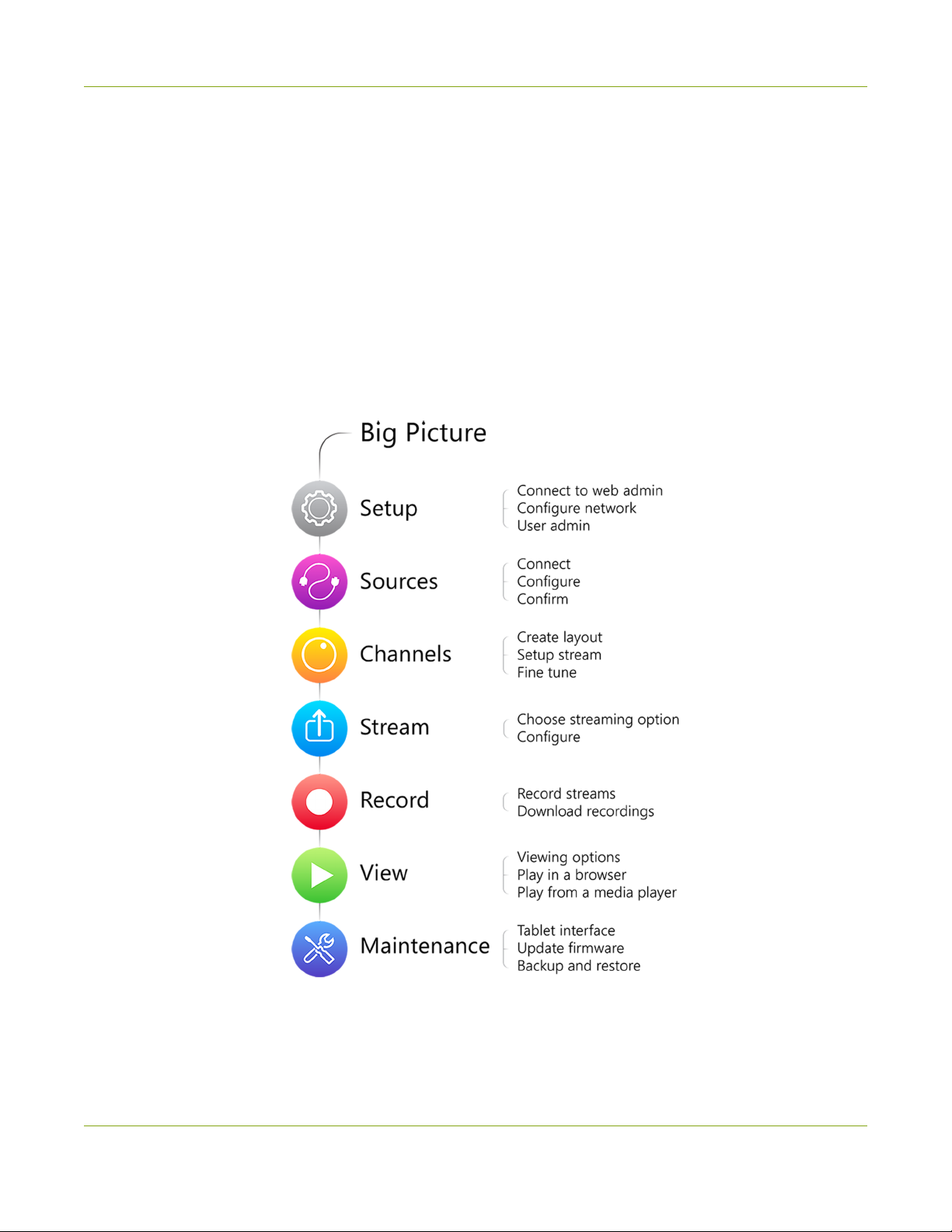
Following the quick start section, a set of task-based procedures help you to tweak the system exactly how you
want it. These procedures are broken into seven categories: Setup, Sources, Channels , Stream, Record, View,
and Maintenance.
1
Page 14

Networked VGAGrid User Guide Welcome
About this Guide
Warnings are depicted as follows.
This is a warning.
Tips and Notes are depicted as follows.
This is a tip.
Throughout this guide there are situations where more than one solution will complete a task. In those cases
the guide describes the simplest or most common variation first.
2
Page 15
Networked VGAGrid User Guide Networked VGAGrid Overview
Networked VGAGrid Overview
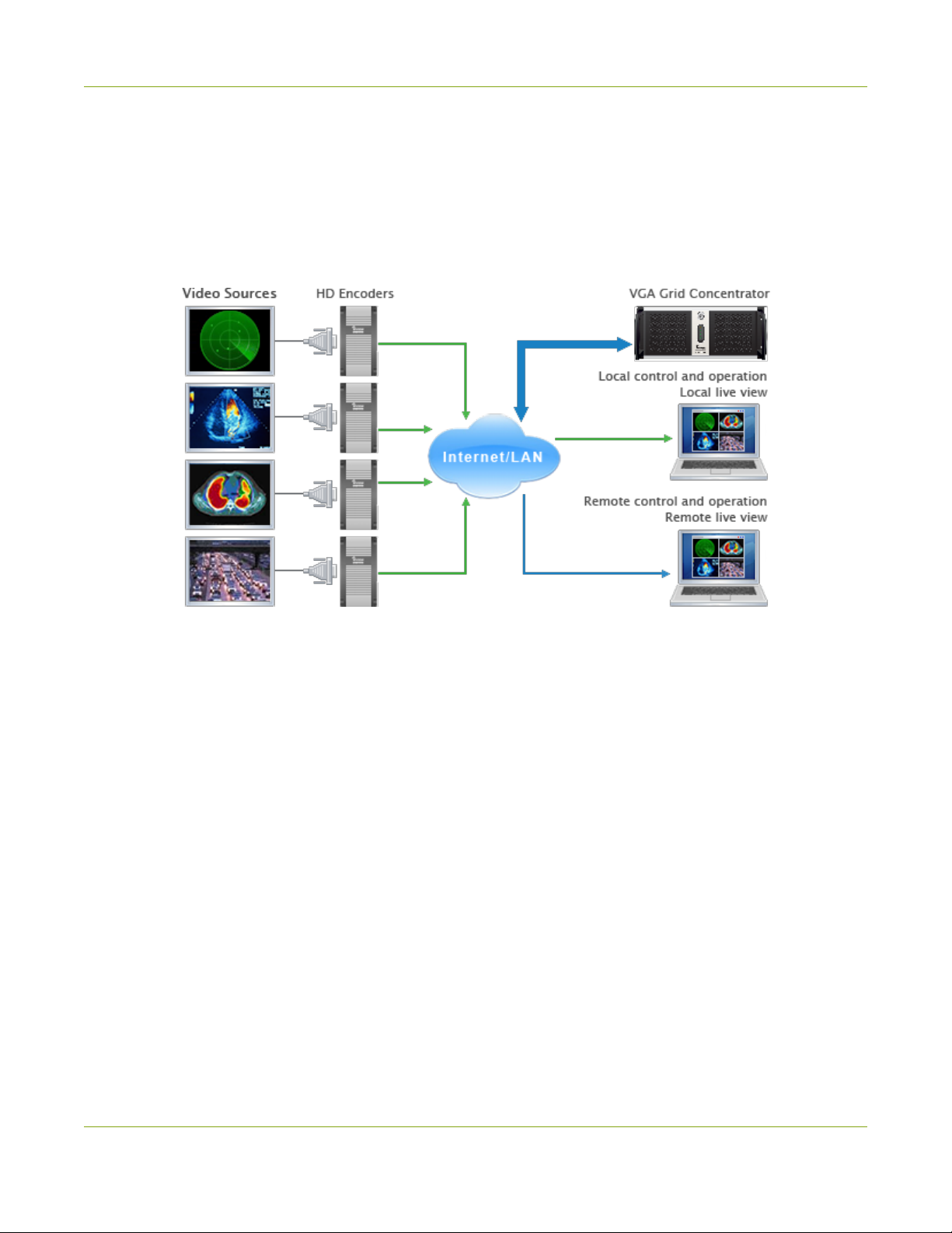
Epiphan's VGAGrid allows you to capture, stream, and record audio and video from a large number of VGA,
DVI, HDMI, composite and component sources. It supports streaming to a large number of viewers using
industry-standard codecs such as H.264 and MPEG-TS. VGAGrid is suitable for a broad range of applications.
This versatile system has a variety of options enabling you to create and configure any number of streaming
channels. You can choose to stream (or record) a single channel at once or a configuration of synchronized
channels with picture-in-picture or picture-with-picture multiplexing selections.
The VGAGrid comes in two styles to meet your needs:Networked and Standalone. The Standalone VGA Grid
captures video and audio through internal cards. Depending on the model it has 4 or 6 DVI source ports, 4 or 6
SDI source ports and 4 or 6 S-Video source ports. The latest hardware models(with SDIcapture) also support
HDMI and SDIaudio catpure. Encoding and synchronization of the stream is done locally on the Standalone
VGA Grid. The Networked VGAGrid has no internal capture cards, instead it uses VGAGrid HD Encoders to
capture and encode sources, sending the already encoded stream to the VGAGrid. Using external encoders
means the VGAGrid has less stress on its CPU so it can handle a greater number of inputs. HDMIaudio capture
and SDI video capture are not supported with Networked VGAGrid systems.
3
Page 16
Networked VGAGrid User Guide What's in the Box?
What's in the Box?
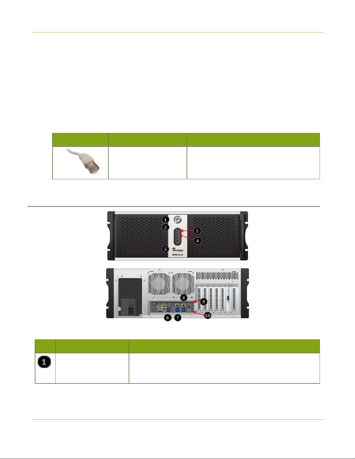
The Networked VGAGrid is a 4U rackmount server with dimensions 522 mm (D) × 430 mm (W) × 176 mm(H)
(20.5” × 16.9” × 6.9”).
The following items are shipped with the system.
1. One Ethernet cable
2. Power cable
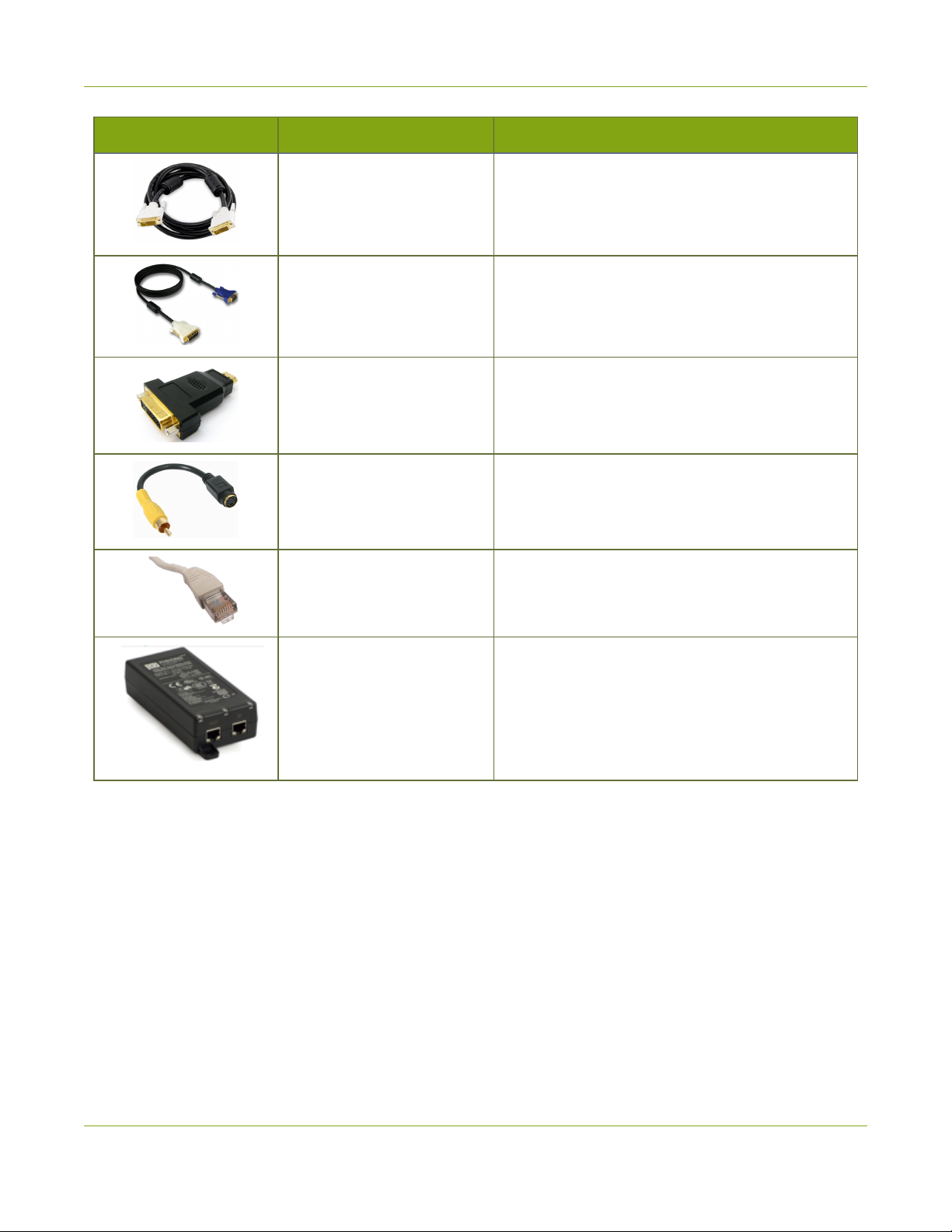
Image Name Description
RJ-45 Ethernet cable Connects the system to your network.
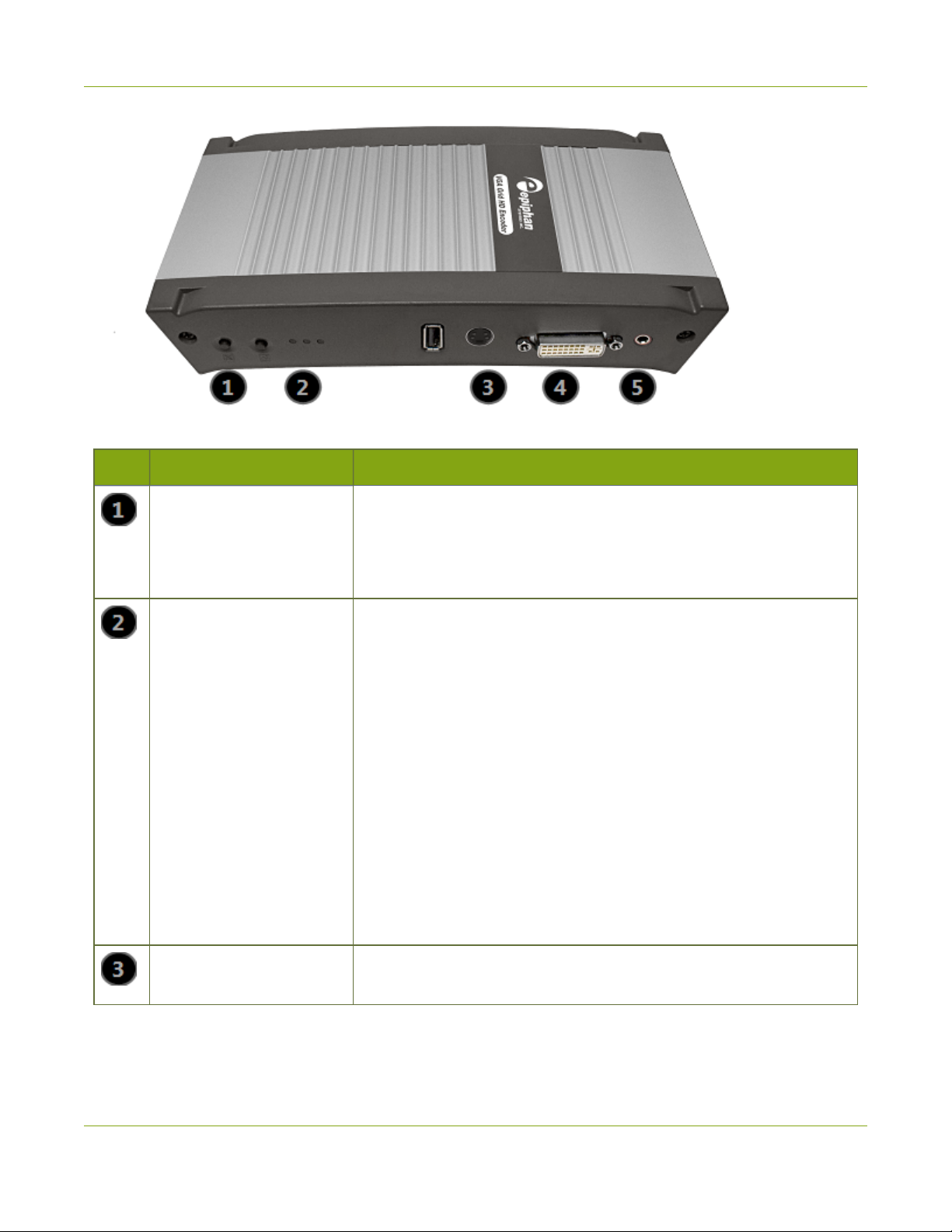
Front and back panel view for the VGAGrid
Table 1 Rackmount Networked VGAGrid Front and Back Panel Descriptions
Label Name Description
Power Button (behind
door)
Unlock the door to reveal the power button.
Press to turn on; press and release to turn off the system.Press and
hold for 4 seconds for a forced system shutdown.
4
Page 17
Networked VGAGrid User Guide What's in the Box?
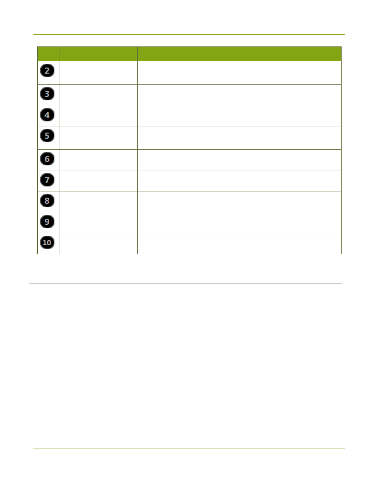
Label Name Description
Reset (behind door)
Power LED Indicates the system is powered on.
Hard Drive LED Blinks when the system is recording or accessing the hard drive.
USB Ports (behind door)
USB Ports For connection of external hard drives, flash drives, or control interfaces.
USB Ports For connection of external hard drives, flash drives, or control interfaces.
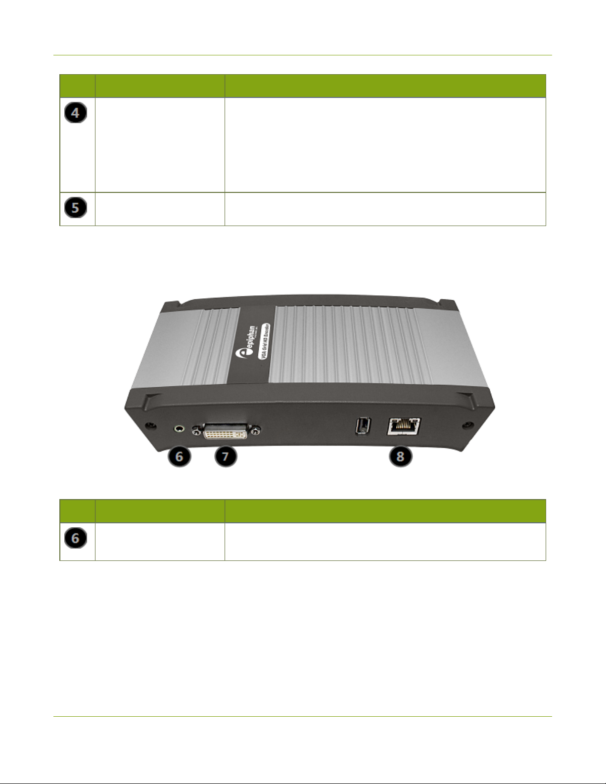
RJ-45 Ethernet Auto-sensing gigabit Ethernet 10/100/1000 Base-T network port.
Audio In (blue) Connect amplified line in audio sources to the system.
Audio In (pink) Connect unamplified microphone audio sources to the system.
Unlock the door to reveal the reset button.
Cycles the power off then on, like a computer reset button.
Unlock the door to reveal two USB ports.
For connection of external hard drives, flash drives, or control interfaces.
VGAGrid HD Encoder overview
VGAGrid HD Encoders are small portable units with a size of 202 mm x 105 mm x 35 mm (7.95” x 4.13” x 1.38”).
Each has one DVI (single link), one S-Video and one audio input.
The following cables come with each VGAGrid HD Encoder you purchase:
1. One VGA to DVI-I cable
2. One HDMI to DVI-I adapter
3. One DVI-I to DVI-I (single link) cable
4. One composite to S-Video cable
5. One Ethernet cable
6. One Power over Ethernet injector
5
Page 18
Networked VGAGrid User Guide What's in the Box?
Image Name Description
DVI-I Single Link cable
VGA to DVI cable
HDMI to DVI adapter
Composite to S-Video cable
RJ-45 Ethernet cable Connects the system to your network.
Connects a DVI source to the encoder’s DVI port
(s).
Connects a VGA source to the system’s DVI port
(s).
Connects an HDMI source to the system’s DVI port
(s).
Connects a composite output from an analog
sources to the system’s S-Video port(s).
Injects power over an ethernet cable. Used to
Power over Ethernet Injector
power the s when the network connection is not
powered.
Front Panel
This section describes the front panel connectors and indicators.
Note, not all connections are used.
6
Page 19
Networked VGAGrid User Guide What's in the Box?
Table 2 VGAGrid HD Encoder Front Panel Descriptions
Label Name Description
Reset button Resets the Networked VGAGrid back to its factory configuration
defaults.
To ensure the device is not accidentally reset, a special sequence is
required. See Perform Factory Reset.
Status LEDs Three LEDs on the front panel indicate the following Networked
VGAGrid status:
Solid blue LED indicates device is starting up.
Solid green LED indicates the device is ready to capture images.
Flashing blue LED indicates:
l a video signal test is in progress;
l system tuning, or
l Networked VGAGrid is recording received images.
Note: If the periodic disk check function occurs during start up, it may
take up to 20 minutes to power up the device. During this time the
blue LED is solid and the green LED flashes. See Storage Disk
Maintenance for more information.
S-video input Connect to an s-video source or a composite video source using the
adapter (included).
7
Page 20
Networked VGAGrid User Guide What's in the Box?
Label Name Description
DVI In Connect to one of the following sources:
l DVI input, use the DVI to DVI cable (included)
l VGA input, use the VGA to DVI adapter (included)
l HDMI input, ( for non-copy protected content), use the HDMI to
DVI adapter (included)
Audio In
Connect to an audio input source.
Back Panel
This section describes the back panel connectors and indicators.
Table 3 VGAGrid HD Encoder Back Panel Descriptions
Label Name Description
Audio Out Connect to audio equipment, such as headphones or speakers, to
confirm the audio stream is captured.
8
Page 21

Networked VGAGrid User Guide What's in the Box?
Label Name Description
DVI Out Connect to video equipment, such as a monitor or projector to confirm
the video stream is captured.
Connect one of the following sources:
l DVI output, use the DVI to DVI cable (included)
l VGA output, use the VGA to DVI cable (included)
Note: This connection can convert a VGA input signal to DVI output
signal.
RJ-45 Attach the provided RJ-45 cable and connect to a powered Ethernet
port. The port is auto-sensing and supports negotiations at 10/100
speeds.
Power over Ethernet is used to power the VGAGrid HD Encoder. If the
network connection does not provide power, use the provided power
over Ethernet injector to power the device.
9
Page 22

Networked VGAGrid User Guide Quick Start
Quick Start
This section helps you get up and running quickly with your Networked VGAGrid.
l Step 1: Physical Setup and Power On
l Step 2: Admin Discovery and Login
l Step 3: Set a static IP address for the encoder
l Step 4: Add the encoder as a channel
l Step 5: Configure the Channel
l Step 6: Testing the Stream
l Step 7: Recording the Stream
Before you get started, make sure you have:
l an HD source (i.e. a computer, a tablet, or a phone)
l the appropriate cables or adapters to convert the output to DVI (if needed)
l a VGAGrid HD Encoder and associated cables
l ideally, a network with Dynamic Host Configuration Protocol (DHCP)
l a computer with a web browser connected to the same network (this is referred to as the “admin”
computer in the steps below)
l optionally, an audio source such as a microphone or the headphone jack from a laptop (note that the
audio signal sent over HDMI cables is not supported)
These instructions include steps for setting up and configuring audio. Skip these optional steps if
you do not want to configure an audio source at this time.
Step 1: Physical Setup and Power On
Complete the following steps to prepare and power on the system. Refer to the Front and Back Panel View
section for your system to locate the appropriate input ports.
1. Turn on your HD source and connect the output cable to the DVI-I port on the VGAGrid HD Encoder.
2. (optional) Attach a 3.5 mm audio cable from your audio source to the VGAGrid HD Encoder's audio
input port.
10
Page 23

Networked VGAGrid User Guide Quick Start
3. If your network connection provides power overEthernet:
a. Connect an Ethernet cable to the VGAGrid HD Encoder. Connect the Ethernet cable to your
network.
If your network connection does not provide power over Ethernet:
a. Connect one end of the power cord into the PoE injector and the other end into a grounded AC
power source.
b. Connect an Ethernet cable from the Ethernet switch port to the RJ-45 connector (labled In) on
the PoE injector.
c. Connect an Ethernet cable from the the RJ-45 connector (labled Out) from the PoE Injector to the
RJ-45 Ethernet port on the back panel of the VGAGrid HD Encoder.
4. Wait for the VGAGrid HD Encoder to complete the power up sequence. The green power LED is
illuminated when boot up is complete.
5. Connect the Ethernet cable to the Networked VGAGrid. Connect the Ethernet cable to your network.
6. Attach the power cable to the system and plug it into a power source.
7. Unlock the front panel and press the power button to turn on the system.
8. Wait for the Networked VGAGrid to complete the power up sequence. The power LED illuminates and
the hard drive LED flashes during start up.
Step 2: Admin Discovery and Login
The Networked VGAGrid is managed from a web interface. This interface acts as a configuration utility and
system monitor. The first time you access the web interface you will not know the IP address of the system.
The steps below use DNS-based service discovery (a type of zero-configuration networking) to access the
system. Depending on the operating system on your admin computer you may need to install some software
before you can used DNS-based discovery.
This quick start is meant for systems that support DHCP and DNS, however if your system does not
support these mechanisms, refer toConnect to the Admin Interface and Connect via the Epiphan
Discovery Utility for alternative discovery mechanisms. Return to step 3 below you have
completed setting a static IP address for the Networked VGAGrid.
11
Page 24
Networked VGAGrid User Guide Quick Start
Table 4 Installing Bonjour Print Services
System Action Needed
Microsoft Windows You must install Bonjour Print Services:
1. Use the following URL - http://support.apple.com/kb/DL999
2. Click Download.
3. Follow the system prompts to download and install the application.
MacOSX The Bonjour software used for service discovery is built in to the Mac OS. No special
actions needed.
Linux The Avahi implementation used for DNS-based discovery is shipped with most Linux
distributions. If necessary, check with your administrator to ensure you have the Avahi
package installed.
You are able to access the system web interface on the local network by specifying its serial number in a web
browser on your admin computer.
1. Find the system’s serial number. It is printed on a sticker on the back of the unit.
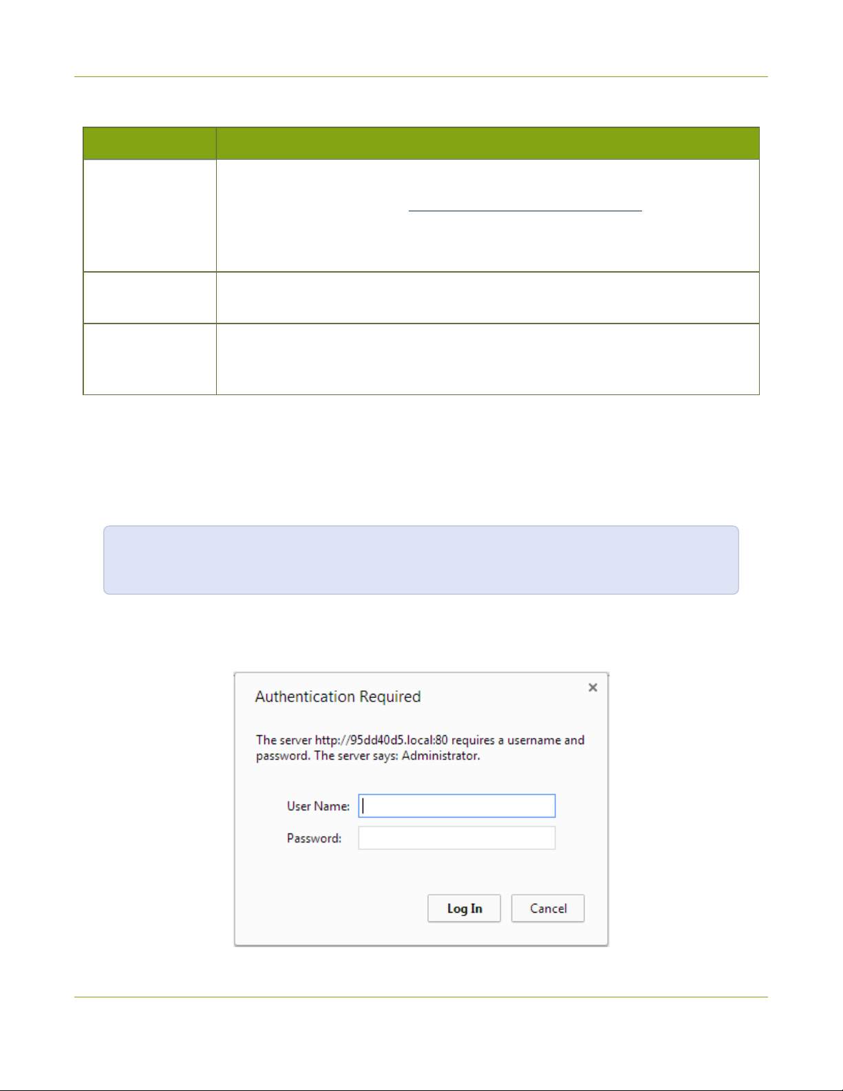
2. Type the following string into the address bar of your web browser on your admin computer (where
<serial> is the serial number of your Networked VGAGrid):
http://<serial>.local/admin
For example: http://95dd40d5.local/admin
3. Enter the user name and password then click OK. The administrative user is ‘admin’. Initially no
password is set. To set a password follow the procedure outlined in Setting and Changing User
Passwords.
12
Page 25

Networked VGAGrid User Guide Quick Start
4. Optionally, navigate to the Network link under the Configuration heading and note the IP address of
the system.
Step 3: Set a static IP address for the encoder
It's recommended that you use static IP addresses for any VGAGrid HD Encoders on your network. Encoders
are connected to the VGAGrid by their IPaddresses. Using static IP addresses ensures that the encoders can
still be located after a system relocation, power failure or other event that may change a dynamically
allocatedIP address for the encoder.
If you have not already set a staticIPaddress for the VGAGrid HD Encoder:
1. Find the VGAGrid HD Encoder's serial number. It is printed on a sticker on the bottom of the unit.
2. Type the following string into the address bar of your web browser on your admin computer (where
<serial> is the serial number of your encoder):
http://<serial>.local/admin
For example: http://98498.local/admin
3. Enter the user name and password then click OK. The administrative user is ‘admin’. Initially no
password is set. To set a password follow the procedure outlined in Setting and Changing User
Passwords.
4. Navigate to the Network link under the Configuration heading; the network configuration page
appears.
5. Select the radio button use static address, if not already selected.
6. Enter the desired IP Address and Network Mask.
7. Enter the Default Gateway address. If you do not have a default gateway for your network, enter the IP
address of the Networked VGAGrid that is found on the Network page in its web interface.
8. Enter the DNS Server address. If you do not have a DNS server, enter the new static IP address of the
system.
9. Click Apply to save the changes; the changes are saved and a message appears asking you to reboot.
10. Select the Maintenance link under the Configuration menu; the maintenance page appears.
11. Click the Reboot Now button near the bottom of the page.
Step 4: Add the encoder as a channel
Fresh out of the box, your Networked VGAGrid isn't aware of any VGAGrid HD Encoders on your network. The
web interface is used to add each encoder as a channel to the VGAGrid.
Whether or not you chose to use a static IPaddress, the next step is to add the encoder as a channel.
13
Page 26
Networked VGAGrid User Guide Quick Start
The serial numbers and IPaddresses for your system will not be the same as the examples shown
below.
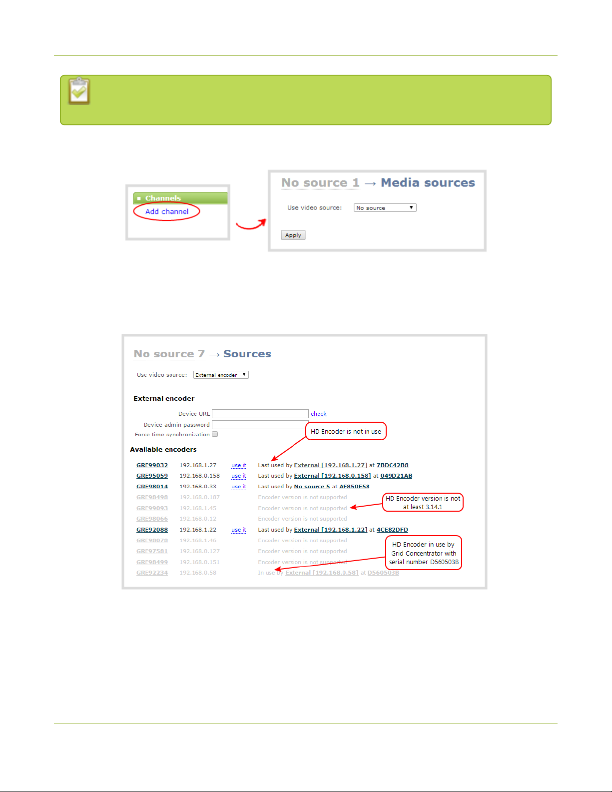
1. From the web interface, scroll to the Channels section and click Add channel; the add channel
configuration page appears.
2. Select External encoder from the Use video source drop-down; the external encoder selection page
appears. Your list should contain just the one VGAGrid HD Encoder set up in Step 1, but if it has several,
like the example below, match the serial number with the serial number printed on the bottom of your
encoder.
3. Copy theIP address for your VGAGrid HD Encoder from the list and paste it in the Device URL field.
4. Leave the admin password blank (this is the default) unless you assigned an admin password earlier.
5. Click Apply; your channel is added as a new channel named External [<ip address>].
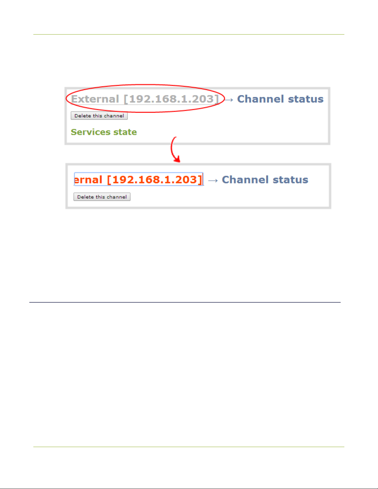
6. Click Status to confirm the new name.
14
Page 27
Networked VGAGrid User Guide Quick Start
7. Rename the channel:
a. Click on the channel name at the top of the channel configuration window. The name text
becomes red.
b. Edit the name to reflect the VGAGrid HD Encoder serial number, or the data it is capturing. The
following characters are supported: a-z; A-Z; 0-9; + (plus); - (hyphen); _ (underscore); , (comma), .
(period); ~ (tilde); #(hash); [ ]; ( ). Although spaces are also supported, it is suggested you use
underscores to separate words.
c. Press Enter on the keyboard. The name is updated at the top of the screen and in the list of
channels at the left side.
Step 5: Configure the Channel
Now that you have confirmed the system sees your source it is time to configure the channel.
To review and configure the channel:
1. From the web interface, scroll to the Channels section
2. Click the link for your channel; the channel expands.
3. Click Encoding for your channel
4. No need to change anything right now. Review some of the default settings. The four most useful
settings to know about are codec, frame size, frame rate and bitrate.
a. The codec is set to H.264 by default.
b. The frame size should reflect the resolution provided by your source. You can set it to something
different by typing in the fields or selecting an option from the different sizes shown. Scaling the
15
Page 28
Networked VGAGrid User Guide Quick Start
image (making it larger, smaller, or different aspect ratio) takes some processing power, so it’s
always best to leave this at the value detected by the system unless you know it is wrong or know
you need to scale the size.
c. The frame rate limit is set to 5. This means the system won’t spend extra computing time to
attempt to receive more than 5 frames per second. For perspective, NTSC TV signals use 24 frames
per second and most hand-drawn animations show only 12 unique frames per second. You can
change this later and notice how it affects performance and quality.
d. The bitrate is set to automatic, and the system will determine the best value.
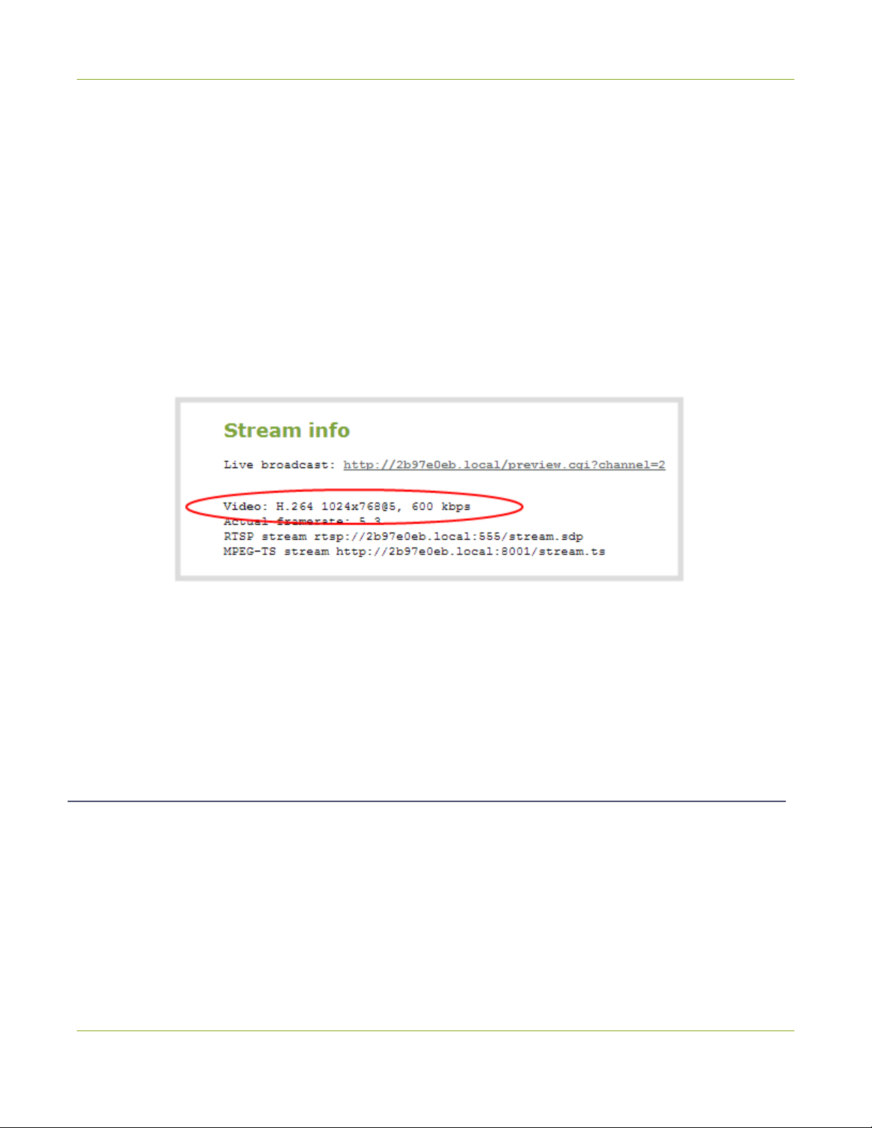
5. Click Status for your channel.
6. Notice the Stream Info section has an item named Video that reflects the four settings reviewed in prior
steps (the frame rate is specified as <resolution size>@5 for 5 frames per second). It also provides an
indication of the current actual frame rate.
You may now optionally add audio to your channel:
7. Click Encoding for your channel; the Encoding page is displayed.
8. Scroll to the bottom of the Encoding and click the Enable audio checkbox.
9. Leave the default AAC format and audio bitrate.
10. Click Apply.
Step 6: Testing the Stream
The Status page contains a link to the live broadcast stream for your channel.
To preview the channel in a browser:
1. From the web interface, scroll to the Channels section.
2. Click the link for your channel.
3. Click the Status link for your channel.
16
Page 29

Networked VGAGrid User Guide Quick Start
4. Right-click on the Live broadcast link for your channel and select Open in a new tab or Open in a new
window.
5. The new tab or window opens with the stream displayed.
a. If the signal is not detected, reseat the DVI cable connections and try again.
Your stream setup is complete. Since most of the steps are pre-configured; you are up and running with a
stream very quickly. You can share the live broadcast link with your users.
Step 7: Recording the Stream
To record the stream:
1. From the web interface, scroll to the Channels section.
2. Click Recording for your channel; the Recording page is displayed.
3. Click the red Start button; the text at the top of the screen changes to indicate the recording is starting,
then indicates the length of time since the recording started.
4. Click the black Stop button; the recorder stops.
5. Refresh the page by clicking Recording again; the page reloads and a file list appears that shows your
newly recorded stream snippet.
6. Click the file name to download and view your recording.
What’s Next?
Now that you have a source setup and ready to stream, you can fine-tune the system to your exact
requirements. You can look at topics such as:
l Add an encoder to the VGA Grid
l Add an encoder as a source for a multi-source channel
l Create a multi-source layout
l Stream your video
l File and recording transfer
l User Administration
When you have completed system tuning, make sure to back up the system configuration using the procedure
described in:
l Save and Restore Device Configuration
Refer to the table of contents for a complete list of the topics covered.
17
Page 30
Networked VGAGrid User Guide PART 1: Setup
PART 1: Setup
If you followed through the quick start guide, you already have a basic configuration and possibly a recording
of an input. Before you tweak the channel or configure more, this part of the manual helps you to get your
Networked VGAGrid properly configured for your network.
Topics covered:
l Connect to the Admin Interface
l User Administration
l View system information
l Configure Network Settings
l Configure Encoder Network Settings
l Configure Date and Time
l Configuration presets
l Restrict Viewers by IPAddress
18
Page 31

Networked VGAGrid User Guide 1-1 Connect to the Admin Interface
1-1
The Networked VGAGrid is managed from a web interface. If you know the IP address of the system you may
type it into the address bar of your web browser.
This section covers two system discovery methods that work with networks that support Dynamic Host
Configuration Protocol (DHCP) and a method that works for networks that do not support DHCP.
For networks with DHCP use one of the following procedures:
For networks without DHCP, use the following procedure:
Connect to the Admin Interface
http://<IP Address of the Networked VGAGrid>/admin
l Connect via DNS-based Service Discovery
l Connect via the Epiphan Discovery Utility
l Connect via Persistent Static IP Address
You can also connect to a reduced Operator tablet interface. See Connect to the tablet interface
Connect via DNS-based Service Discovery
The Networked VGAGrid uses DNS-based messages to advertise details about itself, including its domain
name. With a compatible utility installed on your computer, you can access the system simply by typing its serial
number and the suffix “.local” into the address bar of your browser.
To ensure you have compatible software, refer to the following table.
Table 5 Installing Bonjour Print Services
System Action Needed
Microsoft Windows You must install Bonjour Print Services:
1. Use the following URL - http://support.apple.com/kb/DL999
2. Click Download.
3. Follow the system prompts to download and install the application.
MacOSX The Bonjour software used for service discovery is built into the Mac OS. No special
actions are needed.
19
Page 32

Networked VGAGrid User Guide 1-1 Connect to the Admin Interface
System Action Needed
Linux The Avahi implementation used for DNS-based discovery is shipped with most Linux
distributions. If necessary, check with your administrator to ensure you have the Avahi
package installed.
To access the Networked VGAGrid's web interface via DNS service discovery:
1. Find the system’s serial number. It is printed on a sticker on the back of the system.
2. Type the following string into the address bar of your web browser on your admin computer (where
<serial> is the serial number of your Networked VGAGrid):
http://<serial>.local/admin
For example: http://95dd40d5.local/admin
3. Enter the user name and password then click OK. The administrative user is ‘admin’. Initially no
password is set. To set a password follow the procedure outlined in Setting and Changing User
Passwords.
4. Optionally, navigate to the Network link under the Configuration heading and note the IP address of
the system.
Connect via the Epiphan Discovery Utility
Epiphan provides a utility for discovering Epiphan systems on your network. The Epiphan network discovery
utility is a 32-bit Windows executable that works on most 32-bit and 64-bit Windows operating systems.
Download and install the utility via this link: http://www.epiphan.com/downloads/NetworkDiscovery.exe.
To access the Networked VGAGrid's web interface via the Epiphan discovery utility:
20
Page 33

Networked VGAGrid User Guide 1-1 Connect to the Admin Interface
1. Launch the discovery utility.
2. Click Search to find all the Epiphan systems on the network; a list similar to the following appears.
3. If more than one system appears, select the one you wish to configure by matching the serial number
listed with the serial number marked on the back of the system.
4. Optionally, note the IP Address shown in the stream properties. Use this for quicker access to the
system on future configuration sessions.
5. Click the Web config button; your browser will open and point to the web interface page.
http://<IP Address for Networked VGAGrid>/admin
6. Enter the user name and password then click OK. The administrative user is ‘admin’. Initially no
password is set. To set a password follow the procedure outlined in User Administration.
21
Page 34

Networked VGAGrid User Guide 1-1 Connect to the Admin Interface
Connect via Persistent Static IP Address
This section discusses how to directly connect to the Networked VGAGrid using the factory default persistent
network settings. Use this method if your network does not have a DHCP server or if you prefer to connect
directly to the system for initial configuration.
To perform this procedure you will need a workstation computer for which you are able to modify network
settings.
The Networked VGAGrid is pre-configured with the following static address defaults:
l IP Address: 192.168.255.250
l Netmask: 255.255.255.252
l User Name: admin
l Password: your admin password (by default set to no password)
To access the Networked VGAGrid's web interface via the persistent static IP address:
1. Establish an Ethernet connection between the Networked VGAGrid and the workstation by one of the
following methods:
a. Connect the system to a local Ethernet network shared with the workstation.
b. Connect the system directly to the workstation’s Ethernet port using either a regular or a
crossover Ethernet cable.
2. Record the network settings of the workstation being used to connect to the Networked VGAGrid so
that they can be restored later.
3. Temporarily change the network configuration on the workstation to the following:
a. Use Static IP assignment
b. IP address: 192.168.255.249
c. Subnet mask: 255.255.255.252
4. Start a web browser on the workstation and browse to: http://192.168.255.250/admin/
5. Log in as the administrator user with the user name admin and the admin password (by default there is
no password); the web interface page opens.
6. Click the Networking link in the Configuration menu.
7. Select the radio button to use a static address and configure the system with a static IP address and
network settings relevant to the network being used. For specific details about the settings presented,
see Configure Network Settings.
8. Restore the previously saved network configurations on the workstation.
22
Page 35

Networked VGAGrid User Guide 1-2 User Administration
1-2
The Networked VGAGrid has three configured users:
Each VGAGrid HD Encoder has the same three users. The user accounts are not connected and password
changes must be made to each device in the system individually.
By default, none of these users have passwords. For security purposes you should add passwords to the admin
and operator accounts.
This section describes the following user administration topics:
User Administration
l admin
l operator
l viewer
l Understanding User Privileges
l Setting and Changing User Passwords
l Removing User Passwords
l Overcoming Lost Passwords
l Configure LDAP
l Changing the logged-in user
Understanding User Privileges
Networked VGAGrid's three user accounts are admin, operator and viewer. The user account names cannot be
changed and the accounts cannot be disabled. By default, none of the accounts have passwords.
Admin
The admin account is the main operator used for all system configuration. This user has access to all options in
the web interface.
Operator
The operator account is a subclass of the admin account. The operator can log in and view all configuration
items but may only make changes to a small number of options. This account is intended for an operator to
start and stop recordings, download recordings, or perform network diagnostics.
23
Page 36

Networked VGAGrid User Guide 1-2 User Administration
Viewer
The viewer account is for all end-users who are permitted to view the streamed channels. By default, when
there is no password, users are not prompted for a username and password when viewing a channel. The
viewer username and password prompt appears only when there is a viewer password set.
In addition to the global viewer account, each channel can set a viewer password that overrides the global
value. See Restrict access to streams for viewers.
Current User
When logged in to the web interface, the current username is displayed at the top right corner of the screen.
User Privileges
The following table outlines the privileges for each user:
Table 6 User Privileges in the Web Interface
Action or Menu Option viewer operator admin
View channel output
Channel Operations
View Channel Configuration
Rename a Channel
Configure Stream Channel
Configure Stream Sources
Publish a Stream
Configure Branding for a Channel
Start the Stream Recorder
Stop the Stream Recorder
ü ü ü
ü ü
ü
ü
ü
ü
ü
ü ü
ü ü
View Recorded FilesList
Download RecordedFiles
ü ü
ü ü
24
Page 37

Networked VGAGrid User Guide 1-2 User Administration
Action or Menu Option viewer operator admin
Delete RecordedFiles
Source Operations
View Source Configuration
Rename Source
Configure Source
View Source Snapshot
SystemConfiguration Operations
View System Configuration
Configure Automatic File Upload
Select External USBDrive Behavior
Configure FTPServer
Configure UPnP Sharing
Configure Network Address
ü ü
ü ü
ü
ü ü
ü ü
ü ü
ü
ü
ü
ü
ü
Configure USBTethering
Perform NetworkDiagnostics
Configure Date andTime preferences
Set or Change User Passwords
Configure the Touch Screen
Configure SerialPort Flow Control
Upload Branding Images
Upload Branding Templates
Select BrandingTemplate
Enable Remote Support
Backup Device Configuration
Restore DeviceConfiguration
ü
ü ü
ü
ü
ü
ü
ü
ü
ü
ü
ü
ü
25
Page 38

Networked VGAGrid User Guide 1-2 User Administration
Action or Menu Option viewer operator admin
RestoreFactoryConfiguration
Reboot Device (via Web Interface)
Shutdown Device (via Web Interface)
Configure Time Until Next DiskCheck
Perform DiskCheck
View DiskInformation
Rebuild/Clean Storage Disks
Upgrade Firmware
View System Information
ü ü
ü ü
ü
ü
ü
ü
ü
ü
ü
Setting and Changing User Passwords
By default, admin, operator and viewer have no assigned passwords. Both the admin and the operator user
have access to the web admin interface, so you should always set a password for both admin and operator
accounts. Refer to your system administrator for your organization’s specific password requirements.
In addition to setting global passwords for viewers, you can also set access passwords and IPrestrictions on a
per-channel basis from the channel's Streaming page. See Restrict access to streams for viewersRestrict
Viewers by IPAddress.
Passwords are case sensitive and can use all alpha-numeric keys in the ASCII range. Your password can be up
to 255 characters long, but should not include any spaces.
Setting a user’s password causes the user to be logged out. Be ready to log back in with the new
admin password or have operators and viewers log in with the appropriate new password. Viewers
may need to refresh their browser window or press play in their media player.
If you lose the admin password, refer to the section Overcoming Lost Passwords.
To set a user password:
1. Connect to the admin interface using your preferred connection mechanism. See Connect to the Admin
Interface.
2. Login as admin.
26
Page 39

Networked VGAGrid User Guide 1-2 User Administration
3. Select the Access passwords link in the Configuration menu; the password configuration page opens.
4. Highlight and delete the current password for your selected user (the password is currently masked as
dots).
For security reasons, the current password appears as eight dots regardless of password
length, and even if there is no password set.
5. Highlight and delete the confirmation password for the selected user.
6. Select the user’s password field and type a new password for the user.
The new password must have between 1-255 alpha-numeric characters or special characters
with no spaces. Passwords are case sensitive.
7. Select the user’s password confirmation field and confirm the new password.
8. Click Apply.
9. If you were logged in as the user whose password you just changed, you are logged out and must log
back in with the new password. If you added or changed the viewer’s password, all viewer’s stream will
pause until they log in with the new password.
If desired, you may specify multiple account passwords on the same page before clicking Apply.
Removing User Passwords
If you want to remove passwords for one or more user accounts, you may do so via the web interface. If you
don’t remember the admin password, refer to the section Overcoming Lost Passwords.
Note that viewer passwords can be set on a per-channel basis.
Clearing a user’s password will cause that user to be logged out. Be ready to log back in with the
new admin password. If viewers are watching the broadcast when the viewer password is cleared
they will be logged out. Viewers may need to refresh their browser window or press play in their
media player to trigger the login prompt.
To clear a user’s password:
1. Connect to the admin interface using your preferred connection mechanism. See Connect to the Admin
Interface.
2. Login as admin.
27
Page 40

Networked VGAGrid User Guide 1-2 User Administration
3. Select the Access passwords link in the Configuration menu; the password configuration page opens.
4. Highlight and delete the current password for your selected user (the password is currently masked as
dots).
For security purposes, the current password appears as eight dots regardless of password
length, and even if there is no password set.
5. Highlight and delete the confirmation password for the selected user.
6. Click Apply.
7. If you were logged in as the user whose password you just cleared, you are logged out and must log
back in without a password. If you cleared the viewer’s password, all viewers’ stream will pause until they
log in without a password.
To clear a user’s password on a specific channel:
1. Connect to the admin interface using your preferred connection mechanism. See Connect to the Admin
Interface.
2. Login as admin.
3. Click the Streaming link for the channel; the channel's Streaming configuration page opens.
4. From the Access control section do one of the two following things:
a. clear the viewer password field; or
b. select Use global settings from the access control drop down.
5. Click Apply.
Overcoming Lost Passwords
If you have lost the password for the operator or viewer account, you can log in to the web interface as admin
and reset the password using the procedure described in Setting and Changing User Passwords.
If you have lost the admin password and you have remote support enabled on the system, you can contact
Epiphan support to request a remote password change. See Support. If remote support is disabled, you will
need to return the system toEpiphan for password recovery. Contact Epiphan support to discuss this option.
If you have lost the admin password for the VGAGrid HD Encoder you will need to reset the system to factory
defaults, which resets to the default blank admin password. See Perform Factory Reset.
Configure LDAP
You can use the Lightweight Directory Access Protocol (LDAP) for authentication into the system. Specify user
roles by using group DNs for users who log in as the administrator, operator, or as a viewer.
28
Page 41

Networked VGAGrid User Guide 1-2 User Administration
The system has only one admin user and one operator: LDAP users log in as either the admin or
operator, they do not have their own private profiles.
When enabled, LDAP authentication is an alternative to the regular system usernames and
passwords. You may still login as admin, operator or viewer using the passwords for those
accounts. Furthermore, any LDAPusers with the name admin, operator or viewer are ignored.The
local accounts are used instead.
For security reasons, you should configure passwords for the local accounts. See Setting and
Changing User Passwords.
These instructions assume you have a pre-configured LDAP server. The server must support anonymous
binding or have a special bind account with search access priveleges. (Note that Active Directory does not
support anonymous binding.)
LDAP referrals, restrictions and failovers are not supported.
To configure LDAPauthentication for your Networked VGAGrid:
1. Connect to the admin interface using your preferred connection mechanism. See Connect to the Admin
Interface.
2. Login as admin.
3. Select the Access passwords link in the Configuration menu; the password configuration page opens.
4. Scroll to the LDAPauthentication section.
5. Click the Enable LDAPauthentication checkbox to enable LDAPauthentication (or uncheck to disable).
6. Specify the server IPaddress and (optional) port for your LDAPserver(i.e. 192.168.1.101:389) in the
Server address[:port] field.
29
Page 42

Networked VGAGrid User Guide 1-2 User Administration
7. Use the Connection encryption drop-down to specify the type of encryption, if any used by your LDAP
server.
Connection
encryption
No Encryption No encryption is used to connect to the LDAP server. The default port is 389.
SSL SSL encryption is used to connect to the LDAP server. The default port is 636.
TLS/STARTTLS The connection is initially unencrypted then upgraded to TLS encryption is used.
8. Specify the fully qualified DN and password for LDAPbind in the BindDN and Bind password fields.
(The password masked as dots on the screen.) These fields are only needed if your LDAPserver does not
support anonymous binding.
9. In Base DN, specify the baseObject in which to search for entries. The system will search this object and
the whole subtree starting at the base DN.
10. By default the search attribute is uid, which is suitable for a unix environment. Specify a different value in
the Search attribute field, if needed. For Active Directory environments, specify userPrincipalName. The
value of this attribute must be unique in the BaseDN.
11. In the Administrators (group DN) field, specify the distinguished name of the group users must be part
of to be logged in as the administrator. Users must have the member or unqueMember attribute for the
specified group to be granted Administrator access.
If left blank, LDAP is not supported for Administrators(but can still be used for Operators and Viewers).
Description/Default port used
The default port is 389.
12. In the Operators (group DN) field, specify the distinguished name of the group users must be part of to
be logged in as the operator. Users must have the member or unqueMember attribute for the specified
group to be granted Operator access.
If left blank, LDAP is not supported for Operators (but can still be used for Administrators and Viewers).
13. In the Viewers (group DN) field, specify the distinguished name of the group users must be part of to
be logged in as a viewer. Users must have the member or unqueMember attribute for the specified group
to be granted Viewer access.
If left blank, LDAP is not supported for Viewers (but can still be used for Administrators and Operators).
14. Click Apply.
When a user of the LDAPserver visits next visits the admin or viewer page for the system, the system prompts
for use the username and password. For ActiveDirectory servers, the user needs to enter his the fully qualified
username(i.e. username@domainname) in addition to his LDAPpassword.
Users are required to authenticate once to the system and one time per channel they view.
Therefore users see a prompt to log in to the system (the system name is shown) and a second
time to log in to the channel (the channel name is shown).
30
Page 43

Networked VGAGrid User Guide 1-2 User Administration
In one case, LDAPreplaces the local viewer account instead of working side-by-side with it.
When LDAPis enabled and the viewer account has no password (either there is no global viewer
password or the channel overrides the global password with a blank password), the viewer must
authentication withLDAP, he may not alternatively use the viewer account with a blank password.
Changing the logged-in user
When you log in to the web interface as admin or operator, your browser remembers this configuration and
automatically logs you in as the same user when you go back to the site.
Sometimes you need to change from operator to admin, or vice versa.
To change the logged-in user:
1. Exit your browser completely, open an incognito/private window in your browser, or open a different
browser (i.e. Internet Explorer, Chrome, and Safari are different browsers).
2. Connect to the admin interface using your preferred connection mechanism. SeeConnect to the Admin
Interface.
3. You are prompted for a username and password.
31
Page 44

Networked VGAGrid User Guide 1-2 View system information
1-2
The system information page provides a great deal of useful information about your Networked VGAGrid. Use
the Info link from the Configuration menu to view your current firmware level, system hardware version(if
available) and currently configured channels.
To view system information:
View system information
1. Connect to the admin interface using your preferred connection mechanism. See Connect to the Admin
Interface.
2. Login as admin.
3. From the web interface, scroll to the Configuration menu option.
4. Click Info; the system information page opens.
3. Use the information displayed to get an overview of your system, troubleshoot problems or view
streams for configured channels.
32
Page 45

Networked VGAGrid User Guide 1-3 Configure Network Settings
1-3
By default the Networked VGAGrid uses DHCP to obtain an IP Address via an Ethernet-based network. If you
want to change the network settings, or if you’re having network-related issues, this section covers the
following related topics:
For VGAGrid HD Encoder network settings, see Configure Encoder Network Settings.
Configure Network Settings
l Verify IP Address and MAC address
l Configure a Static IP Address
l Configure DHCP
l Tether to a Mobile Network
l Perform Network Diagnostics
Verify IP Address and MAC address
The web interface shows you the system’s MAC address and current IP Address via the Network configuration
page.
To view settings on network configuration page:
1. Connect to the admin interface using your preferred connection mechanism. See Connect to the Admin
Interface.
2. Login as admin.
3. Select the Network link in the Configuration menu; the network configuration page opens.
4. Note the MAC address and Current IP address listed at the top of the page.
33
Page 46

Networked VGAGrid User Guide 1-3 Configure Network Settings
Table 7 Network InformationFields
Label Description/Options
MACAddress A media access control address (MAC address) is a unique identifier for the
network interface. The value is read-only and cannot be changed. You may need
to share this value with your system administrator.
Current IPAddress Reflects the current internet protocol address (IP address) of the system. This
value is either obtained from the DHCP server (if using DHCP) or is the configured
static IP address. The Networked VGAGrid supports IPv4 addresses. It does not
support IPv6 addresses.
Configure a Static IP Address
Your network administrator may require you to use a static IP address for your Networked VGAGrid.
To configure a static IP address:
1. Connect to the admin interface using your preferred connection mechanism. See Connect to the Admin
Interface.
2. Login as admin.
3. Select the Network link in the Configuration menu; the network configuration page opens.
4. Select the radio button use static address, if not already selected.
5. Enter the desired IP Address and Network Mask.
Only IPv4 addresses are supported.
34
Page 47

Networked VGAGrid User Guide 1-3 Configure Network Settings
6. Enter the Default Gateway address. If you do not have a default gateway for your network, enter the
same static IP address as in the previous step.
The default gateway cannot be left blank. If no default gateway is specified, unexpected
behavior occurs.
7. Enter the DNS Server address. If you do not have a DNS server, enter the new static IP address of the
system.
8. Change the MTU Size value only if needed. See the table below for information on maximum
transmission unit (MTU) values.
9. Click Apply to save the changes; the changes are saved and a message appears asking you to reboot.
10. Select the Maintenance link under the Configuration menu; the maintenance page appears.
11. Click the Reboot Now button near the bottom of the page.
12. Wait for the system to reboot.
13. Open the Web interface using the new IP address.
14. Log as admin and reload the Networking page to verify all changes were applied.
The following table describes applicable fields when setting a static IP address.
Table 8 Static IPAddress Fields
Label Description/Options
Use DHCP Select this radio button to dynamically obtain an IP address at boot up.
Use static address Select this radio button to use the configured static IP address.
IP Address The internet protocol address (IP Address) to assign. This value is may be obtained
from your system administrator. The Networked VGAGrid supports IPv4 addresses. It
does not support IPv6 addresses.
Network Mask Also called the subnet mask, this value denotes a range of IP addresses. This value may
be obtained from your system administrator, determined from another computer on
the same subnet, or calculated using an online subnet calculator.
35
Page 48

Networked VGAGrid User Guide 1-3 Configure Network Settings
Label Description/Options
Default Gateway The network node that serves as an access point to the rest of the network. This value
cannot be blank unless you are using DCHP. Specify the system’s IP address if you don’t
have a default gateway on your network.
DNS Server The domain name system server (DNS server) translates human-readable hostnames
into corresponding IP addresses. Specify the system’s IP address if you don’t have a
DNSserver on your network. This value cannot be blank unless you are using DHCP.
MTU Size The maximum transmission unit (MTU) specifies the maximum packet size for transfer
on the network. The default value is 1500, which is the largest value allowed by
Ethernet at the network layer. It’s best if all nodes in your network use the same value,
so only change this value if you know other nodes use a different value.
Configure DHCP
Occasionally, such as when moving your system to a new network, your Networked VGAGrid must switch from
static IP address allocation to dynamic allocation via DHCP. You can accomplish this three ways:
l Restore factory settings, clearing all your custom settings. See Perform Factory Reset.
l Load a configuration file that uses DHCP networking. See Load a saved device configuration.
l Apply a configuration preset that usesDHCP networking. See Apply a configuration preset .
l Change the network settings. See the procedure below.
To configure use of DHCP for networking:
1. Connect to the admin interface using your preferred connection mechanism. See Connect to the Admin
Interface.
2. Login as admin.
3. Select the Network link in the Configuration menu; the network configuration page opens.
4. Select the radio button use DHCP, if not already selected.
5. Change the MTU Size value only if needed. See the table below for information on maximum
transmission unit (MTU) values.
6. Click Apply to save the changes; the changes are saved and a message appears asking you to reboot.
36
Page 49

Networked VGAGrid User Guide 1-3 Configure Network Settings
7. Select the Maintenance link under the Configuration menu; the maintenance page appears.
8. Click the Reboot Now button near the bottom of the page.
9. Wait for the system to reboot.
10. Connect to the admin interface using your preferred connection mechanism. SeeConnect to the Admin
Interface.
11. Log as admin and reload the Networking page to verify all changes were applied.
The following table describes the fields applicable when configuring DHCP on the Networked VGAGrid.
Table 9 DHCP Fields
Label Description/Options
Use DHCP Select this radio button to dynamically obtain an IP address at boot up.
Use static
address
MTU Size The maximum transmission unit (MTU) specifies the maximum packet size for transfer on
Use static address Select this radio button to use the configured static IP address.
the network. The default value is 1500, which is the largest value allowed by Ethernet at the
network layer. It’s best if all nodes in your network use the same value, so only change this
value if you know other nodes use a different value.
Tether to a Mobile Network
The Networked VGAGrid supports tethering to a mobile device via USB. Tethered networking can work sideby-side with Ethernet routing and either networking system can be a back-up for the other.
When the system falls over to the backup network type (i.e. from Ethernet to mobile, or vice versa)
all streaming sessions with clients or servers directly connected to the system are closed and the
clients will need to reconnect. You may need to provide a new stream URL(containing the new
IPaddress) to your viewers. See the channel information page to get the new stream URL.
By contrast, actively published streams are closed and reconnected via the secondary network
(mobile or Ethernet) automatically, permitted the required publishing server is accessible from the
new network.
37
Page 50

Networked VGAGrid User Guide 1-3 Configure Network Settings
To configure tethering to a mobile network:
1. Configure the mobile device to allow tethering via USB.
2. Connect the mobile device to the Networked VGAGrid with a USB cable.
3. Connect to the admin interface using your preferred connection mechanism. SeeConnect to the Admin
Interface.
4. Login as admin.
5. Select the Network link in the Configuration menu; the network configuration page opens.
6. Click the drop-down box next to Use phone/tablet connection in the USB phone/tablet section; the
following choices appear:
Table 10 Mobile Tethering Options
Label Description/Options
Disabled Specifies that no USB tethering is permitted.
No tethering Specifies that USB tethering is available for connecting a mobile device as a
configuration utility (i.e. using the web browser), but no mobile data is used.
Prefer ethernet When chosen, the system tries to use the Ethernet network first. It switches to use
the mobile network (tethering) when the Ethernet network is no longer available.
To prevent viewer interruptions, mobile data will continue to be used until the
mobile network is down or publishing is restarted.
Prefer
tethering
7. Select your choice based on the table above.
8. Click Apply.
When chosen, the system tries to use the mobile network (tethering) first. It
switches to use Ethernet (hard-wired) when the mobile network is no longer
available. To prevent viewer interruptions, Ethernet data will continue to be used
until the Ethernet network is down or publishing is restarted.
Select this setting if you only have a mobile network.
Perform Network Diagnostics
If your Networked VGAGrid has network trouble, you can perform basic network troubleshooting tasks from
the Network configuration page. In addition to providing the system’s IP address and MAC address to your
network administrator (See Verify IP Address and MAC address), you can also ping an IP address or use
traceroute to determine the path taken to an address.
Note: Not all networks support ping and traceroute.
38
Page 51

Networked VGAGrid User Guide 1-3 Configure Network Settings
To ping or traceroute an IP address:
1. Connect to the admin interface using your preferred connection mechanism. See Connect to the Admin
Interface.
2. Login as admin.
3. Select the Network link in the Configuration menu; the network configuration page opens.
4. Click ping or traceroute; an animation appears to the left of the address to indicate processing is
underway.
5. Upon completion of the command, read the results from the console-like display is shown below the
Network Diagnostics setting.
39
Page 52

Networked VGAGrid User Guide 1-3 Configuration presets
1-3
In situations where you have changing configuration requirements for your Networked VGAGrid, you can use
configurationpresets to quickly and easily apply sets of pre-configured settings.
For an overview of configuration presets, see:
This section also covers the following related topics:
There are also some very important configuration preset considerations to review:
Configuration presets
l Configuration presets overview
l Configuration groups
l Create a configuration preset
l Apply a configuration preset
l Apply theFactory default configuration preset
l Update a configuration preset
l Delete a configuration preset
l Configurationpreset considerations
Configuration presets overview
Configuration presets make it easy to use your Networked VGAGrid in a variety of situations without needing
to reconfigure it. Configuration presets divide the system's settings into the following configuration groups.
(For a complete list of what is included in each group see Configuration groups.)
System Sources Automatic file uploads
Network Channels
Using the Configuration presets section of the Maintenance page, you can create configuration presets using
any number and combination of the configuration groups. Mix and match the settings groups saved together
to create sets of configuration settings needed for each situation. You also always have a special Factory
default configuration preset (which cannot be erased) to help you return to factory configuration without
destructively erasing files saved to the system hard drive. (See Apply theFactory default configuration preset
40
Page 53

Networked VGAGrid User Guide 1-3 Configuration presets
It's important to note that configuration presets are applied over existing settings. They affect only the settings
groups included in the preset, all other settings are unaffected. Read the Configurationpreset considerations
section carefully to understand caveats around using configuration presets.
Example of configuration presets in action
A recording and streaming company brings Networked VGAGrid to a conference as part of a portable rack.
Each conference session needs to be streamed and recorded with a picture in picture layout that includes
identifying information about the presenter in the metadata and the background image for the stream.
Automatic file upload is needed to make sure the files are uploaded right after each session is complete.
The company could bring Networked VGAGrid in a factory configured state and get it ready between each
session, but this requires a trained operator and doesn't allow much time to get multiple operations
completed.
Instead, the company could connect the system to their own corporate network before the show, upload the
required backgrounds, and create channel configuration presets for each conference track. They can also
create network and automatic file upload (AFU) presets for each of the home and remote locations. Once at
the conference, the only changes necessary are to apply the network and AFU preset upon arrival, and the
channel configuration presets between sessions.
Note: channel configuration presets include links to background files used, but do not include the files
themselves see Branding content
Internal network and AFU preset
The company uses this preset when configuring and testing from their corporate network. It uses a static IP
address on their corporate network and AFU that uses ftp to upload to a local ftp server.
Conference network and AFUpreset
The company applies this preset to the Networked VGAGrid when they arrive at the conference. It changes
only the network and AFU settings (using a conference-specific IP address and secure file transfer to an ftp
server).
When applying this configuration preset, all other information including passwords, date/time, channels and
source configurations, remains the same.
41
Page 54

Networked VGAGrid User Guide 1-3 Configuration presets
Conference session 1 preset
The company applies this preset from the corporate office when testing and at the conference prior to
conference session 1 starting. All other preset groups remain unchanged, this preset only affects the channel
(s) and their configuration. This preset includes a channel with a link to the correct background filename (the
background file was uploaded during pre-show configuration at the corporate office) and has metadata
specifying the speaker's name.
Conference session 2 preset
The company applies this preset from the corporate office when testing and at the conference prior to
conference session 2 starting. After applying this preset the files recorded from session 1 remain present on
the system and continue to upload via sftp (if not yet complete), but the channels reflect the session 2
background file name and presenter name.
42
Page 55

Networked VGAGrid User Guide 1-3 Configuration presets
Configuration presets are a versatile tool to help you use Networked VGAGrid in a variety of changing
conditions. Try it yourself and see!
Configuration groups
The following table describes what settings are saved with each configuration group.
Table 11 Configuration group definitions
Group Name Symbol Settings included in the configuration group
Date and time settings, serial port settings, remote support settings, custom
System
Network Network settings and tethering configuration.
disk check schedule, access passwords, deny/allow lists and LDAPconfiguration
settings
Sources All audio and video source configuration settings.
All channel configuration data and current recording state, all recorder
Channels
AFU Automatic file upload type and parameters.
Note that branding content, recorded files and SFTP/SCP private keys are not included in any
configuration preset.
Updloaded EDID configurations are applied immediately to the system and remain the norm for
the source until a new EDID is uploaded. Configuration presets do not affect EDIDs.
configuration data and current recording state, individual and global UPnP
settings.
Create a configuration preset
You can create as many configuration presets as you need. The system keeps track of which configuration
groups are part of the preset and you provide a name that lets you know the significance of the preset.
43
Page 56

Networked VGAGrid User Guide 1-3 Configuration presets
Note that configuration presets that include network or system settings require a system reboot
when applied.
To create a configuration preset:
1. Connect to the admin interface using your preferred connection mechanism. See Connect to the Admin
Interface.
2. Login as admin.
3. Select the Maintenance link in the Configuration menu; the maintenance page opens.
4. Scroll to the Configuration presets section.
5. Type a description for your preset in the Name field.
6. Ensure only the desired configuration groups are selected from the Sections group.
7. Click Save; your configuration preset appears in the list.
44
Page 57

Networked VGAGrid User Guide 1-3 Configuration presets
Apply a configuration preset
When you apply a configuration preset, the system settings for all included configuration groups are updated.
Other settings on the system are not affected. For example if you apply a preset that includes the configuration
groups channnels and automatic file upload, your network settings, passwords, time server, source
configurations, etc are not modified. Similarly if you apply a configuration preset that has only network
settings included, only the network settings change.
If you apply a preset that has the network or system configuration group, a reboot is required.
You can verify which configuration groups are included in a preset by looking at the list to the right of the
configuration preset name. The term 'all' means all groups are included. Otherwise groups are listed
individually.
You may apply multiple presets one after another. If you apply two (or more) configuration presets
that include a particular configuration group, the settings (for that group) from the last applied
preset are the active settings. In short, last in wins.
To apply a configuration preset:
1. Connect to the admin interface using your preferred connection mechanism. See Connect to the Admin
Interface.
2. Login as admin.
3. Select the Maintenance link in the Configuration menu; the maintenance page opens.
4. Scroll to the Configuration presets section.
5. Click Apply next to the configuration preset you wish to apply.
6. The system asks for confirmation before proceeding.
45
Page 58

Networked VGAGrid User Guide 1-3 Configuration presets
If the configuration preset includes the network or system configuration groups, a reboot
is necessary.
7. ClickOK to apply the configuration preset; the configuration preset is applied.
8. The system reboots if needed.
Apply theFactory default configuration preset
Your Networked VGAGrid comes with a special factory default configuation preset.This configuration preset
cannot be erased and is always presented at the top of the configuration presets list. It contains all possible
configuration settings groups.
Using the Factory default configuration setting is similar to using the Factory reset method(see Perform
Factory Reset with a few important differences.
In short, the Factory default configuration preset is less destructive than Factory reset. This table describes
the exact differences.
Table 12 Factory default configuration preset vs Factory reset
Deletes all created channels
Deletes all recorded files in channels
Deletes all created recorders
Deletes all recorded files in recorders
Resets network configuration
Resets touch screen configuration
Resets user passwords
Factory default
configuration preset
ü ü
ü
ü ü
ü
ü ü
ü ü
ü ü
Factory reset function
Deletes all created configuration presets
ü
46
Page 59

Networked VGAGrid User Guide 1-3 Configuration presets
Deletes all branding files
Resets all Source settings
Deletes all Automatic file upload settings
To apply the factory default configuratin preset, follow the instructions in Apply a configuration preset and
select the Factory default preset. A reboot is required.
Factory default
configuration preset
ü
ü ü
ü ü
Factory reset function
Update a configuration preset
If you need to update a configuration preset to include different configuration groups, or simply new settings
for the same groups, you can do so easily via the web interface.
To update a configuration preset:
1. Connect to the admin interface using your preferred connection mechanism. See Connect to the Admin
Interface.
2. Login as admin.
3. Select the Maintenance link in the Configuration menu; the maintenance page opens.
4. Scroll to the Configuration presets section.
5. Find the preset you wish to change from the presets list.
6. Copy the name of the preset into the Name field.
47
Page 60

Networked VGAGrid User Guide 1-3 Configuration presets
7. Selected the desired configuration group(s) from the Sections group.
8. Click Save; a confirmation dialog asks you to confirm you want to overwrite the configuration preset.
9. Click OK; your configuration preset is updated in the list.
Delete a configuration preset
You may want to trim the list of configuration presets to only those that are needed for your ongoing needs.
You can delete all configuration presets at once by doing a factory reset, or you can delete individual
configuration presets from theMaintenance page.
To delete a configuration preset:
1. Connect to the admin interface using your preferred connection mechanism. See Connect to the Admin
Interface.
2. Login as admin.
3. Select the Maintenance link in the Configuration menu; the maintenance page opens.
4. Scroll to the Configuration presets section.
48
Page 61

Networked VGAGrid User Guide 1-3 Configuration presets
5. Click delete (x) next to Apply for the configuration preset; a confirmation message appears.
6. Click OKto confirm you want to delete the preset; the preset is deleted.
Configurationpreset considerations
Configuration presets are groups of settings applied to the system, leaving other settings intact. The following
considerations will help you get the most from your configuration presets.
Channel and recorder index number behavior
Each channel and recorder has an index number. The first channel created on a system is channel 1,
subsequently channel 2, 3, 4, etc. Recorders are also created starting at index 1 with numbers incrementing as
new recorders are created. The channel (or recorder) index number is found to the left of the channel or
recorder name in the web interface:
49
Page 62

Networked VGAGrid User Guide 1-3 Configuration presets
Configuration presets that contain the channels configuration group specify the channels in the preset by
their index number. This means if you have channels 1, 2, 3 and 4 when you save your preset, applying that
preset will overwrite the configuration of your current channels with indexes 1, 2, 3 and 4. If prior to applying
that preset you also had channels with indexes 5 and 6, the configuration settings for those two channels are
when the preset is applied(because the preset only has 4 channels).
There are three areas where channel (and recorder) index numbers affect what happens when applying
configuration presets. Read Recording StateRecorded files (in channels and recorders) and Deleting channels
for more information.
Recording State
The Configuration groups section of this chapter shows that each channel and recorder's recording state is
included in the channels configuration group. This means that if a channel (or recorder) is recording at the
time you create a configuration preset, it will immediately start recording when you apply that preset. Similarly,
if a configuration preset is saved when channels or recorders are not recording, those channels and recorders
will not be recording when the preset is applied (this means a channel or recorder may stop recording as a
result of applying the preset).
For example, when applying a preset with channel 3 set to record:
l If channel 3 exists prior to applying the preset and is already recording, the file will continue recording
uninterrrupted unless the recording file type is differentin the preset (in which case a new file is started).
l If channel 3 exists prior to applying the preset and is not already recording, it immediately begins
recording.
l If no channel with index 3 exists prior to applying the preset, the channel is created and it immediately
begins recording.
Recorded files (in channels and recorders)
Channels and recorders keep a list of files recorded in theirRecordings section of the web interface. These files
remain on the system even if the channel or recorder configuration is changed or removed as a result of
applying a configuration preset.
50
Page 63

Networked VGAGrid User Guide 1-3 Configuration presets
For example, prior to applying your configuration preset, you have channels with indexes 1, 2 and 3; each of
these has five recording files. When you apply a configuration preset that has channels with index 1 and 2 only,
you'll notice those channels each still have the same 5 recording files. Channel with index 3 is no longer
present, but the files are not lost!
Overwritten channel files are still available. To access and download/delete these recorded files, enter the
following into the address bar: http://<deviceIP>/admin/channelN/archive or
http://<deviceIP>/admin/recorderN/archive, where N is the index of the removed channel/recorder.
For example, if a Channel with index 3 is no longer present, its corresponding files can be accessed by
entering the following into the address bar:
l http://192.168.0.183/admin/channel3/archive
If you now create a new channel with index 3 (or load a preset that contains a channel with index 3), you'll find
it starts with five recorded files in the Recordings section. These are the same recorded files that existed at the
start of this example.
Furthermore, if you delete any of the recordings, you are deleting the only instance of those files. Using our
previous example, if you delete one of the five recordings from channel index 1, you'll find that even after
applying different presets channel 1 will have only four recorded files.
Deleting channels
Recorded files are stored on the system based on their channel or recorder number. All files saved for channel
index 1 are in one folder, and all files for recorder index 2 are in another. When you delete a channel (or
recorder), you permanently delete all recordings for that channel (or recorder) even if those recordings were
made while a different preset is applied.
Note applying a configuration preset with a different set of channels or recorders is not the same
as deleting a channel.
When deleting a channel or recorder that has recorded files, the web interface warns you of other
configuration presets that use the same channel or recorder index numbers. When you see this prompt, we
recommend you take a moment to look through the Recordings list to make sure you're OK to proceed with
permanently deleting all the recorded files.
51
Page 64

Networked VGAGrid User Guide 1-3 Configuration presets
Branding content
The channels configuration group includes the filenames for logos and backgrounds used in the currently
configured channels. It does not include the image files. Therefore it is important to make sure that between
uses of different channel-related configuration presets you do not delete or replace files listed in the Branding
Content section of the web interface. There is currently no configuration group that includes the Branding
Content files.
EDIDs
EDIDs are uploaded and immediately applied to a specific source. This change remains in place until the user
uploads a new EDID or requests the factory EDID is applied by using the Restore default EDID button (see
Force the capture card to use a specific EDID
If you apply a preset that needs a special EDID, be sure to remember to upload that EDID after applying the
configuration preset.
Configuration presets are not user profiles
Configuration presets should not be confused with the concept of user profiles. Specifically, the following
issues arise from trying to use configuration presets as user profiles:
l recorded files are not removed between application of configuration presets (users could see each other's
files)
l configuration presets can be overwritten and deleted with no password (users could affect each other's
presets)
l branding and recorded files can be deleted, affecting more than just the currently applied configuration
presets (users could erase branding or recordings belonging to other users)
l applying a configuration presets does not clear the settings from groups not part of the preset (user
information is not private)
52
Page 65

Networked VGAGrid User Guide 1-3 Configuration presets
HDEncoder considerations
When saving configuration presets for Networked VGAGrid, it's recommended that you save both the sources
and the channels configuration groups. This is particularly important if you are using multi-source layouts that
employ local channels as sources.
Additionally, care is needed to make sure that VGAGrid HD Encoders are accessible and not in use by another
VGAGrid Concentrator before applying a configuration preset using those HDEncoders.
Examples:
1. If an applied configuration preset creates a channel that employs a local source but that local source is
not found (e.g. was not part of the configuration preset and is not presently configured on the system),
the no signal image is used for that source.
2. If a configuration preset creates a source that is a local channel, but the channel is not presently
configured and was not part of the configuration preset, the source has no signal.
3. If a configuration preset creates a channel containing anHDEncoder that is currently in use by another
VGAGrid Concentrator, no warning is presented to the user and unexpected behaviour occurs. Neither
VGAGrid Concentrator has full control of the VGAGrid HD Encoder.
4. If a configuration preset creats a channel containing a VGAGrid HD Encoder cannot be found on the
network, no warning is presented to the user. The Concentrator continues to try to find the
HDEncoder, in the same fashion it would if an already configured HDEncoder is disconnected from the
network.
53
Page 66

Networked VGAGrid User Guide 1-4 Configure Encoder Network Settings
1-4
It's recommended that you use static IP addresses for any VGAGrid HD Encoders on your network. Encoders
are associated to the VGAGrid by their IPaddresses. Using static IP addresses ensures that the encoders can
still be located after a system relocation, power failure or other event that may change a dynamically
allocatedIP address for the encoder.
This section covers the following network configuration changes for the VGAGrid HD Encoder:
Additionally, the following general network topics are applicable to encoders. Log into the encoder's web
interface when following the described procedures:
Configure Encoder Network Settings
l Verify IP Address and MAC address
l Set a static IP address for the encoder
l Configure DHCP for the encoder
l Tether to a Mobile Network
l Perform Network Diagnostics
Verify IP Address and MAC address
The web interface shows you the system’s MAC address and current IP Address via the Network configuration
page.
To view settings on network configuration page:
1. Find the VGAGrid HD Encoder's serial number. It is printed on a sticker on the bottom of the unit.
2. Follow the instructions in Connect to the Admin Interface to connect to the VGAGrid HD Encoder (use
the serial number from step 1 above, not the serial number of the VGAGrid).
3. Login as admin.
4. Select the Network link in the Configuration menu; the network configuration page opens.
5. Note the MAC address and Current IP address listed at the top of the page.
54
Page 67

Networked VGAGrid User Guide 1-4 Configure Encoder Network Settings
Table 13 Network InformationFields
Label Description/Options
MACAddress A media access control address (MAC address) is a unique identifier for the
network interface. The value is read-only and cannot be changed. You may need
to share this value with your system administrator.
Current IPAddress Reflects the current internet protocol address (IP address) of the system. This
value is either obtained from the DHCP server (if using DHCP) or is the configured
static IP address. The VGAGrid HD Encoder supports IPv4 addresses. It does not
support IPv6 addresses.
Set a static IP address for the encoder
If you have not already set a staticIPaddress for the VGAGrid HD Encoder:
1. Find the VGAGrid HD Encoder's serial number. It is printed on a sticker on the bottom of the unit.
2. Follow the instructions in Connect to the Admin Interface to connect to the VGAGrid HD Encoder (use
the serial number from step 1 above, instead of the serial number of the VGAGrid).
3. Login as admin.
4. Navigate to the Network link under the Configuration heading; the network configuration page opens.
5. Select the radio button use static address, if not already selected.
6. Enter the desired IP Address and Network Mask.
Only IPv4 addresses are supported.
55
Page 68

Networked VGAGrid User Guide 1-4 Configure Encoder Network Settings
7. Enter the Default Gateway address. If you do not have a default gateway for your network, enter the
new static IP address of the Networked VGAGrid that is found on the Network page in its web
interface.
The default gateway cannot be left blank. If no default gateway is specified, unexpected
behavior occurs.
8. Enter the DNS Server address. If you do not have a DNS server, enter the new static IP address of the
system.
The DNSServer address cannot be left blank. If no DNSServer is specified, unexpected behavior
occurs.
9. Click Apply to save the changes; the changes are saved and a message appears asking you to reboot.
10. Select the Maintenance link under the Configuration menu; the maintenance page appears.
11. Click the Reboot Now button near the bottom of the page.
The following table describes applicable fields when setting a static IP address.
Table 14 Static IPAddress Fields
Label Description/Options
Use DCHP Select this radio button to dynamically obtain an IP address at boot up.
Use static address Select this radio button to use the configured static IP address.
IP Address The internet protocol address (IP Address) to assign. This value is may be obtained
from your system administrator. The VGAGrid HD Encoder supports IPv4 addresses. It
does not support IPv6 addresses.
Network Mask Also called the subnet mask, this value denotes a range of IP addresses. This value may
be obtained from your system administrator, determined from another computer on
the same subnet, or calculated using an online subnet calculator.
Default Gateway The network node that serves as an access point to the rest of the network. This value
cannot be blank. Specify the VGAGrid’s IP address if you don’t have a default gateway
on your network.
DNS Server The domain name system server (DNS server) translates human-readable hostnames
into corresponding IP addresses. Specify the VGAGrid HD Encoder or VGAGrid’s IP
address if you don’t have a DNSserver on your network.
56
Page 69

Networked VGAGrid User Guide 1-4 Configure Encoder Network Settings
Label Description/Options
MTU Size The maximum transmission unit (MTU) specifies the maximum packet size for transfer
on the network. The default value is 1500, which is the largest value allowed by
Ethernet at the network layer. It’s best if all nodes in your network use the same value,
so only change this value if you know other nodes use a different value.
Configure DHCP for the encoder
If you have not already set a staticIPaddress for the VGAGrid HD Encoder:
1. Find the VGAGrid HD Encoder's serial number. It is printed on a sticker on the bottom of the unit.
2. Follow the instructions in Connect to the Admin Interface to connect to the VGAGrid HD Encoder (use
the serial number from step 1 above, instead of the serial number of the VGAGrid).
3. Login as admin.
4. Navigate to the Network link under the Configuration heading; the network configuration page
appears.
5. Select the radio button use DHCP, if not already selected.
6. Change the MTU Size value only if needed. See the table below for information on maximum
transmission unit (MTU) values.
7. Click Apply to save the changes; the changes are saved and a message appears asking you to reboot.
8. Select the Maintenance link under the Configuration menu; the maintenance page appears.
9. Click the Reboot Now button near the bottom of the page.
10. Wait for the system to reboot.
11. Connect to the VGAGrid HD Encoder's admin interface using your preferred connection mechanism. See
Connect to the Admin Interface.
12. Log as admin and reload the Networking page to verify all changes were applied.
The following table describes the fields applicable when configuring DHCP on the VGAGrid HD Encoder.
57
Page 70

Networked VGAGrid User Guide 1-4 Configure Encoder Network Settings
Table 15 DHCP Fields
Label Description/Options
Use DCHP Select this radio button to dynamically obtain an IP address at boot up.
Use static
address
MTU Size The maximum transmission unit (MTU) specifies the maximum packet size for transfer on
Use static address Select this radio button to use the configured static IP address.
the network. The default value is 1500, which is the largest value allowed by Ethernet at the
network layer. It’s best if all nodes in your network use the same value, so only change this
value if you know other nodes use a different value.
58
Page 71

Networked VGAGrid User Guide 1-5 Configure Date and Time
1-5
The Networked VGAGrid uses the current date and time in naming recorded files and when synchronizing and
timestamping inputs from multiple sources (i.e. when synchronizing an audio and a video source). The admin
interface lets you specify date and time settings to ensure they are correctly configured for your time zone and
your network. This section covers the following date and time-related topics:
Remember to log into the encoder's admin interface when performing any date and time related configuration
changes to a VGAGrid HD Encoder.
Configure Date and Time
l Verify Date and Time Settings
l Change the Time Zone
l Configure Synchronized Time (NTP, PTP v1, and RDATE)
l Configure a Local NTP Server
l Manually Configure the Date and Time
l Synchronize Date and Time for Encoders and Grid
Epiphan recommends enabling the local NTPserver on the VGAGrid and using this as the time
synchronization point for each encoder.
Verify Date and Time Settings
The current date, time, time zone, and synchronized time protocol settings are shown when the Date and Time
configuration page is loaded in the Networked VGAGrid web interface.
To view settings on the date and time configuration page:
1. Connect to the admin interface using your preferred connection mechanism. See Connect to the Admin
Interface.
2. Login as admin.
3. Select the Date and Time link in the Configuration menu; the date and time configuration page opens
and the following information is displayed:
59
Page 72

Networked VGAGrid User Guide 1-5 Configure Date and Time
The date and time configuration page also indicates whether the system is currently using synchronized or
manually set time, and whether or not a local network time protocol (ntp) server is running.
The following table describes the date and time configuration fields.
Table 16 Date and Time Options
Label Description/Options
Time Zone The currently selected time zone.
Enable time
synchronization
Protocol The time synchronization protocol.
ServiceIPAddress The time synchronization server address.
Set time manually Whether or not time is set manually. (If time is not being set manually, a time
Date The current date. (This is the current date even if the radio button Set time manually is
Time The current time. (This is the current time even if the radio button Set time manually is
Whether or not a time synchronization protocol is being used for setting time. (If not
selected, time is set manually.)
synchronization protocol is used.)
not selected.)
not selected.)
Change the Time Zone
By default the system has the Canada/Eastern time zone set. Configuration of the time zone is necessary to
ensure synchronized time servers provide the correct time to the system.
To select another time zone:
1. Connect to the admin interface using your preferred connection mechanism. See Connect to the Admin
Interface.
60
Page 73

Networked VGAGrid User Guide 1-5 Configure Date and Time
2. Login as admin.
3. Select the Date and Time link in the Configuration menu; the date and time configuration page opens.
4. Select the new time zone from the Time Zone drop down box.
5. Click Apply.
Configure Synchronized Time (NTP, PTP v1, and RDATE)
By default the Networked VGAGrid uses the network time protocol server (NTP server) protocol and a time
server from National Research Council Canada. You can continue to use this time server or configure a new
server that is more appropriate for your network and location. Your system administrator can provide the
correct time synchronization server settings.
To set the time synchronization method:
1. Connect to the admin interface using your preferred connection mechanism. See Connect to the Admin
Interface.
2. Login as admin.
3. Select the Date and Time link in the Configuration menu; the date and time configuration page opens.
4. Click the Enable time synchronization radio button if it is not already selected.
5. Choose one of the following choices from the Protocols drop down:
Table 17 Synchronized Time Options
Label Description/Options
NTP Network Time Protocol (NTP) is used for clock synchronization over the internet.
There are many publicly available NTP servers you can use, or your company may
have its own NTP server. For more information about NTP and to find NTPservers,
refer to http://support.ntp.org/bin/view/Servers/WebHome.
RDATE RDATE is a tool for querying the current time from the network. It is generally
considered obsolete and has been replaced by NTP. It's offered here for
backwards compatibility with older timekeeping systems.
PTP v1 The Precision Time Protocol (PTP) is used for clock synchronization over the
internet. It has clock accuracy in the sub-microsecond range, making it more
granular than NTP.
6. Tailor the synchronization protocol with the required parameters as described below.
7. If NTP is selected:
a. Enter the IP address or server name for the NTP server in the Server IP Address field.
61
Page 74

Networked VGAGrid User Guide 1-5 Configure Date and Time
NTP uses UDP packets and port 123. If the system is behind a firewall and accessing an
external NTP server, UDP packets must be permitted on port 123.
8. If RDATE is selected:
a. Enter the IP address or server name for the RDATE server in the Server IP Address field.
b. Select an update interval from the drop down box.
9. If PTP v1 is selected:
a. Select the multicast address of PTP v1 server from the PTPdomain drop-down.
PTP Domain Description
Default PTPat multicast address 224.0.1.129
Alternative 1 PTPat multicast address 224.0.1.130
Alternative 2 PTPat multicast address 224.0.1.131
Alternative 3 PTPat multicast address 224.0.1.132
PTP uses UDP packets and ports 319 and 320 . If the system is behind a firewall and
accessing an external PTP server, UDP packets must be permitted on ports 319 and 320.
10. Click Apply.
Configure a Local NTP Server
The Networked VGAGrid can run a local NTP server that all encoders can use as their NTP server. Using a local
NTP server means that the encoders and VGAGrid will share the same time. Synchronization will be accurate,
even if your network has no external time server available.
To configure a local NTP server:
1. Connect to the admin interface using your preferred connection mechanism. See Connect to the Admin
Interface.
2. Login as admin.
3. Select the Date and Time link in the Configuration menu; the date and time configuration page opens.
4. Select the check box Enable local NTP server.
If your network has access to an external time server, set the Grid to point to the external server and keep all
encoders pointing to the Grid’s local NTP server.
62
Page 75

Networked VGAGrid User Guide 1-5 Configure Date and Time
Manually Configure the Date and Time
By default the Networked VGAGrid uses NTP for time synchronization. If your system does not have access to a
time synchronization server, or if you do not wish to use one, you can choose to manually set the date and
time.
To manually set the date and time:
1. Connect to the admin interface using your preferred connection mechanism. See Connect to the Admin
Interface.
2. Login as admin.
3. Select the Date and Time link in the Configuration menu; the date and time configuration page opens.
4. Type the desired date in the Date field. Use the format yyyy-mm-dd.
5. Type the desired time in the Time field. Use the format hh:mm:ss.
6. Click Apply.
Synchronize Date and Time for Encoders and Grid
Date and time are used to synchronize streams coming into the Networked VGAGrid. Therefore, it's important
to ensure that the VGAGrid and all associated VGAGrid HD Encoders share the same date and time settings.
You can accomplish this by configuring each system to use to the same external time server, but for best results
we recommend you enable the local NTPServer on your VGAGrid and have the encoders use this as the
synchronized time source.
To configure synchronized time using a local NTPserver on the VGAGrid:
1. Follow the steps here to Configure a Local NTP Server configure the VGAGrid. Use the VGAGrid's admin
interface.
2. Connect to the Networked VGAGrid's admin interface using your preferred connection mechanism.
SeeConnect to the Admin Interface.
3. Login as admin.
4. Select the Sources link for your channel; the sources configuration page opens.
63
Page 76

Networked VGAGrid User Guide 1-5 Configure Date and Time
5. Check the Force time synchronization checkbox if it is not already selected.
6. Click Apply.
For other time synchronization methods, see Configure Synchronized Time (NTP, PTP v1, and RDATE).
64
Page 77

Networked VGAGrid User Guide 1-6 Restrict Viewers by IPAddress
1-6
The Networked VGAGrid permits you to restrict which computers can access broadcasts by building a list of
allowed and/or denied IP addresses. You can do this at a global level for the system and can also override these
settings on a per-channel basis. Both global and per-channel configuration procedures are described below.
If your viewer account has a password, your viewers must connect to the system from a computer (or gateway)
with a permitted IP address and must also supply the username (viewer) and password before they can view
the broadcast.
To restrict access by IP address you need to know the IP addresses, or range of addresses for your viewers. By
default all IP addresses are allowed to connect to the broadcast.
If you’re not familiar with creating allow/deny lists, refer to the examples below this procedure for assistance
with crafting your lists.
Restrict Viewers by IPAddress
IP address restriction is valid for the viewer only and does not affect the web admin interface or the
mobile configuration interface.
IP Address restriction is not configurable per channel. Restrictions affect all broadcasts / streams
from the system.
To restrict viewers by IP address:
1. Connect to the admin interface using your preferred connection mechanism. See Connect to the Admin
Interface.
2. Login as admin.
3. Select the Access passwords link in the Configuration menu; the password configuration page opens.
4. Type allowed IP addresses or address ranges in the Allow IP’s field. Separate addresses with a comma.
5. Type denied IP addresses or address ranges in the Deny IP’s field. Separate addresses with a comma.
6. Click Apply.
To restrict viewers of a specific channel by IPaddress:
1. Connect to the admin interface using your preferred connection mechanism. See Connect to the Admin
Interface.
2. Login as admin.
65
Page 78

Networked VGAGrid User Guide 1-6 Restrict Viewers by IPAddress
3. Select the Streaming link for the desired channel; the streaming configuration page opens.
4. From the Access Control drop-down, select Use these Settings; local password and Allow/Deny IP lists
are enabled.
5. If desired, type a password for the viewer in the Viewer Password field.
6. Type allowed IP addresses or address ranges in the Allow IP’s field. Separate addresses with a comma.
7. Type denied IP addresses or address ranges in the Deny IP’s field. Separate addresses with a comma.
8. Click Apply.
If a user attempts to connect to the stream from a disallowed IPaddress, access is denied. If connecting by
internet browser, the message "IPaddress rejected." is displayed.
The following table describes the applicable fields.
Table 18 IP Based Restriction Fields
Label Description/Options
Allow IP's Enter individual IP Addresses or IP Address ranges, separated by commas. To specify a
range, use a hyphen (-). Optional spaces improve readability.
Users connecting from addresses in this list are permitted to view broadcasts from the
system, provided their IP address is not in the Deny IP’s list.
To allow all (except IP addresses in the deny list, if any), leave the field blank.
You can use the Allow list by itself, or in conjunction with the Deny IP’s list as an exception
to a rule in the allow list.
Deny IP's Enter individual IP Addresses or IP Address ranges, separated by commas. To specify a
range, use a hyphen (-). Optional spaces improve readability.
Users connecting from addresses in this list are not allowed to view broadcasts from the
system, unless their IP address is in the Allow IP’s list. If a specific IP address is in both lists,
access to the stream is denied.
You can use the Deny list by itself, or in conjunction with the Allow IP’s list as an exception
to a rule in the allow list.
Examples
Allow List with Distinct IP Addresses
The simplest allow/deny list is to use the list of known IP addresses to craft a list of allowed IP addresses. All
other addresses are denied access to the broadcast.
66
Page 79

Networked VGAGrid User Guide 1-6 Restrict Viewers by IPAddress
For example if your system is accessible on your local area network (LAN) and you want to make sure only the
CEO’s specific desktop, laptop and tablet computers (with IP Addresses 192.168.1.50, 192.168.1.51, and
192.165.1.75, respectively) can connect to the broadcast, construct the following allow list:
Allow: 192.168.1.50, 192.168.1.51, 192.168.1.75
Allow List with a Range of IP Addresses
Sometimes you’ll want a range of computer IP addresses to connect to your system. This may happen when
you have one range of IP addresses assigned to desktop computers (i.e. in the range 192.168.1.1 to
192.168.1.100) and another range assigned to boardroom computers (i.e. the range 192.168.1.200 to
192.168.1.250). If you only want the boardroom computers to connect to broadcasts from the system you can
specify the range of boardroom IP addresses rather than needing to type in each individual address. The allow
list looks as follows:
Allow: 192.168.1.200-192.168.1.250
Note that we could have specified two of the IP addresses in the previous example as a range.
Allow List with a Range of IP Addresses and One or More Specific IP
Addresses
Putting the first two examples together, we want to permit access to IP addresses in the range of boardroom
computers (192.168.1.200-192.168.1.250) and also want to add the desktop, laptop and tablet computers of the
CEO (IP addresses 192.168.1.50, 192.168.1.51, and 192.168.1.75, respectively). Note the first two IP addresses are
consecutive, so they can be added as a second range. Add these IP addresses to the list as follows:
Allow: 192.168.1.200-192.168.1.250, 192.168.1.50-192.168.1.51, 192.168.1.75
Your list can have multiple ranges and multiple distinct IP addresses, provided they are separated by commas.
Deny List with Distinct IP Addresses
Another simple allow/deny list is to use the list of known IP addresses to list specific denied IP addresses. All
other addresses are allowed access to the broadcast.
For example imagine your system is accessible on your local area network (LAN) and you want to allow any
computer on the LAN can access the stream except your publicly-accessible boardroom (with IP address
192.168.1.211). You can use the following deny list (leave the allow list empty) to permit all computers except
the boardroom computer:
67
Page 80

Networked VGAGrid User Guide 1-6 Restrict Viewers by IPAddress
Deny: 192.168.1.211
As with Allow lists, your deny list can specify a range of IP addresses, and can specify multiple ranges or distinct
IP addresses in a comma-separated list.
Allow List with a Range of IP Addresses, Distinct IP Addresses, and an
Exception
Building on the previous examples, consider the situation where you want the CEO’s computers (192.168.1.50,
192.168.1.51, 192.168.75) and all boardroom computers (192.168.1.200-192.168.1.250) to access the broadcast,
with the exception of the public boardroom computer (192.168.1.211). Use both allow and deny lists to create
the rule as follows:
Allow: 192.168.1.200-192.168.1.250, 192.168.1.50-192.168.1.51, 192.168.1.75
Deny: 192.168.1.211
Both lists can have multiple ranges and multiple distinct IP addresses, provided they are separated by commas.
Deny List with a Range of IP Addresses
Converse to the previous examples, consider the situation where you want every computer on the network to
access the broadcast, with the exception of the CEO’s desktop, laptop, and tablet computers. Additionally,
boardroom computers should not be permitted with the exception of the cafeteria computer (IP address
192.168.1.222).
The deny list is an "exception" list for the allow list. So to craft the rule described above we need to allow all the
computers in the local subnet, then deny specific sub-ranges including two groups of boardroom computers
ensuring the cafeteria computer's IP address is not in the deny list:
Allow: 192.168.1.1-192.168.1.250
Deny: 192.168.1.200-192.168.1.221, 192.168.1.223-192.168.1.250, 192.168.1.50-192.168.1.51, 192.168.1.75
68
Page 81

Networked VGAGrid User Guide PART 2: Sources
PART 2: Sources
Now that you know how to connect to the admin interface, you are ready to configure your input sources. The
following sections provide an overview of the types of sources you can connect to your Networked VGAGrid
and how to configure each source.
The following topics are covered:
l Identify sources
l Configure a video source
l Configure an audio source
l Fine-tune source configuration
69
Page 82

Networked VGAGrid User Guide 2-1 Identify sources
2-1
A source can be an image, video, or audio from a camera, a computer screen or any device that provides a VGA,
S-Video, DVI or HDMI video signal and audio signal output. For the Networked VGAGrid, sources are remote
from the VGAGrid and are connected to VGAGrid HD Encoders.
This chapter covers the following sections:
Identify sources
l Connecting sources
l Previewing captured stream from sources
Connecting sources
You can connect sources to the Networked VGAGrid at any time, either before or after the system is powered
on. Similarly you can disconnect a source from a port and even connect a different source at any time.
Changing the source connected to a port that is being streamed or recorded can result in the
recording stopping or the stream frame size changing depending on how your channel is
configured.
If the frame size changes, viewers may be disconnected and need to re-connect to the stream.
Connect the input sources to the following input ports on the system:
Table 19 Cable and port connections
Cable Input Port
VGA, HDMI or DVl DVI port
composite or S-video source S-Video port
audio Audio Input port
The web interface automatically discovers all input source ports and displays them in the Stream Setup section
of the encoder's channel on the VGAGrid web admin interface after the encoder is added as a channel to the
VGAGrid. (See Add an encoder to the VGA Grid).
When a source is connected to an encoder, the system automatically detects and adjusts the image capture
settings at start up and continues to adjust every 60 seconds during operation (interval is configurable). The
system’s goal is to produce the best quality captured image given the source equipment used. Generally no
further configuration is needed. Fine tuning is available through the VGAGrid HD Encoder's web interface.
70
Page 83

Networked VGAGrid User Guide 2-1 Identify sources
Previewing captured stream from sources
You can preview the images captured from your sources in the web admin interface.
To preview the captured stream/images:
1. Connect to the VGAGrid HD Encoder's admin interface using your preferred connection mechanism.
SeeConnect to the Admin Interface.
2. Login as admin.
3. Ensure a source is connected to the input port, see Table Cable and port connections.
4. From the web interface, click the source name from the Sources menu; the source configuration page
opens.
5. From the web interface, click the Info link; the info page opens.
6. Click screenshot to preview the captured stream.
7. To preview an S-Video stream, go to the Setup page and enable S-Video then repeat the previous two
steps.
71
Page 84

Networked VGAGrid User Guide 2-2 Configure a video source
2-2
This section covers the following video source configuration topics:
For topics related to fine tuning for specific problems or for uploading a custom EDID, see Fine-tune channel
configuration.
Configure a video source
l Configure the video source's frame grabber parameters
l Change a source name
Configure the video source's frame grabber parameters
After attaching the source to the VGAGrid HD Encoder, the next steps are to ensure you have set up static
networking for the encoder (if desired) and to add the encoder as a channel to the Networked VGAGrid. See
Configure Encoder Network Settings and Add an encoder to the VGA Grid.
Generally the captured stream doesn't require any additional configuration, but if needed, you can log into the
encoders web interface to make configuration changes.
To configure a source complete these steps in the VGAGrid HD Encoder's web interface:
The following adjustments cannot be made for S-Video sources.
1. Connect to the VGAGrid HD Encoder's admin interface using your preferred connection mechanism.
SeeConnect to the Admin Interface.
2. Login as admin.
3. Ensure a source is connected to the input port, see Table Configure a video source.
4. From the web interface, click Frame Grabber from the Configuration menu; the Frame Grabber
Adjustments page opens.
5. Make fine adjustments if required, however in most cases the video is ready to view from a channel and
ready to stream.
DVIand HDMISignals
Although many options can be listed on the .vga (DVI) source configuration page, only certain ones are
applicable to DVIor HDMI signals. When you have a digital source connected, the page indicates that most
changes are not configurable.
72
Page 85

Networked VGAGrid User Guide 2-2 Configure a video source
The following values are configurable for digital sources connected to the DVI port:
Value Description
Interval between
VGA signal and
autoadjustments
(sec)
Rotate This feature is useful when a source captures video that is rotated 90⁰ or is
Enable
deinterlacing
When a source is setup, the system automatically detects and adjusts the image
capture settings at start up and continues to adjust every 60 seconds during
operation. To change the number of seconds between update, enter a value, or
0 to disable the feature, otherwise the default of 60 seconds is set.
displayed upside down. Choose one of the following values to change the video
orientation while streaming:
l No rotation
l 90⁰ clockwise
l 90⁰ counter clockwise
l 180⁰
Enable this feature to convert an interlaced source signal to a non-interlaced
signal.
VGA Signals (coming in via DVI port)
The following values are configurable for VGA signals coming in via aDVIport.
73
Page 86

Networked VGAGrid User Guide 2-2 Configure a video source
Value Description
Use signal from Specify the native color space of the signal source, either RGB or YUV. The
following values are available:
l VGA/DVI signal (RGB) (this is the default setting)
l Component signal (YCrCb)
Configurable for VGA sources only.
Interval between
VGA signal and
autoadjustments
(sec)
Vertical shift When an image is not aligned in the window, use this feature to move an image
Horizontal shift When an image is not aligned in the window, use this feature to move an image
Phase Specifies phase adjustments for VGAsignals. Generally not used unless value is
PLL adjustment Changing the value adjusts the horizontal resolution of the image. Adjust the
When a source is setup, the system automatically detects and adjusts the image
capture settings at start up and continues to adjust every 60 seconds during
operation. To change the number of seconds between update, enter a value, or
0 to disable the feature, otherwise the default of 60 seconds is set.
up or down on the screen. The values range from 20 (moves the image up) to –
20 (moves the image down).
left or right on the screen. The values range from -999 (moves the image to the
left) to 999 (moves the image to the right).
provided by Epiphan support.
Configurable forVGA sources only.
value using small increments until the image is sharper. The value ranges from 0999 to 999.
Configurable for VGA sources only.
Offset The Offset and Gain parameters function as contrast control for an image. The
Offset controls the darker parts of the image and the gain controls the bright
parts of the image. Adjust both values to optimize image quality. Adjust the
values using small increments until the image is sharper. If you set Offset to a
high value, set a high value for the gain to balance the two.
Gain The Gain and Offset parameters function as contrast control for an image. The
Gain controls the bright parts of the image and Offset controls the darker parts
of the image. Adjust both values to optimize image quality. Adjust the values
using small increments until the image is sharper. If you set Offset to a high
value, set a high value for the Gain to balance the two.
74
Page 87

Networked VGAGrid User Guide 2-2 Configure a video source
Value Description
Aspect Ratio Sets the aspect ratio of the captured image. The default is 4:3. Set the value to
Wide mode when capturing images that have a wide aspect ratio. Using the
incorrect setting causes the image to be distorted or stretched.
HSync threshold Adjust horizontal sync detection.
Configurable for VGA sources only.
VSync threshold Adjust vertical sync detection.
Configurable for VGA sources only.
S-Video Signals
The following options are available for S-Video signals via S-Video ports.
Signal type Specify the video source connected to the S-Video input source. The options are
Default, Composite, S-Video.
Change a source name
Source names are used when adding sources to channels, therefore it is important that you know the name of
the source you wish to use. If a channel has only one source, it's name will automatically be the same as its
source. Sometimes it's helpful to configure the source name to match the data it's capturing so it's clear what
the channel is capturing too. Alternately you can change the channel's name. See Rename a channel.
To change a source name:
1. Connect to the admin interface using your preferred connection mechanism. See Connect to the Admin
Interface.
2. Login as admin.
3. From the web interface, scroll to the Sources menu option.
4. Click the source link; the source configuration page opens.
5. Click the source name at the top of the page; the name turns red.
6. Highlight and delete the existing source name.
7. Type a new source name.
8. Press Enter (on your keyboard) to save the new name.
75
Page 88

Networked VGAGrid User Guide 2-2 Configure a video source
You must press Enter to save the new name. The Apply button will not save the source
name change.
76
Page 89

Networked VGAGrid User Guide 2-3 Configure an audio source
2-3
Use the following sections to configure the audio settings that control the audio input:
Add an audio source to a channel
Configure audio encoding settings
Set audio volume
View audio signal strength
Configure an audio source
Configure an audio source
All available video formats support audio except Motion JPEG.
Add an audio source to a channel
To add an audio source to a channel complete these steps in the VGAGrid's web interface after adding the
encoder as a channel (see Add an encoder to the VGA Grid):
1. Ensure an audio input source is connected to the VGAGrid HD Encoder.
2. Connect to the admin interface using your preferred connection mechanism. SeeConnect to the Admin
Interface.
3. Login as admin.
4. From the web interface, click Encoding for the encoder's channel; the Encoding page opens.
5. Scroll to the Audio Settings section.
6. Click Enable audio.
7. Click Apply.
Configure audio encoding settings
To configure audio encoding settings complete these steps in the VGAGrid's web interface:
1. Connect to the admin interface using your preferred connection mechanism. See Connect to the Admin
Interface.
2. Login as admin.
3. From the web interface, scroll to the channel section and click the channel for which you want to
configure audio settings; the menu expands.
77
Page 90

Networked VGAGrid User Guide 2-3 Configure an audio source
4. Click Encoding for the encoder's channel; the Encoding configuration page opens.
5. Scroll to Audio settings.
6. Check Enable audio check box.
7. If the default audio format (PCM 22KHz) is not desired, click the Audio format drop-down menu to
select an audio codec. See Fine-tune channel configuration for help choosing one of the supported
audio codecs.
If desired, you can choose Mono to have left and right stereo channels combined and
streamed together (i.e. when listening to the streamed audio, the same blended sound will
come through both the left and right channels).
8. Click the Audio channels drop-down menu to choose mono (1 channel) or stereo (2 channels).
9. Click the Audio bitrate drop-down menu to choose the audio transmission speed. Increasing this value
produces better sound quality but uses more system bandwidth to transmit the audio signal.
For stereo audio, we recommend 256 kbps or 320 kbps.
10. Click Apply.
Set audio volume
To set audio volume complete these steps in the VGAGrid HD Encoder's web interface (note this is done on the
encoder, and not the VGAGrid):
78
Page 91

Networked VGAGrid User Guide 2-3 Configure an audio source
1. Ensure an audio input source is connected to an audio input port.
2. Connect to the VGAGrid HD Encoder's admin interface using your preferred connection method.
SeeConnect to the Admin Interface.
3. Login as admin.
4. From the web interface, scroll to the Configuration section.
5. Click Audio; the following window opens.
6. Select the Input source from the drop-down menu. Choose Line (default setting), to capture system
audio, or choose Mic to capture audio from a microphone connected to the audio input port.
7. Click the Input Amplifier volume drop-down menu. A list of percentages is displayed. Choose to amplify
the volume by a percentage of the original volume. The default setting is 30%. Decrease the percentage
if the output volume is too loud. Increase the percentage if the output volume is not loud enough.
Adjusting the Input Amplifier volume adjusts the recorded and streamed output audio.
8. Enable Microphone 20dB boost to provide additional amplification for the microphone inputs.
9. Click Apply.
View audio signal strength
An audio meter indicates the signal strength of an audio source. If the signal is weak you may experience
volume quality issues. You can adjust the output volume on the audio source and/or adjust the capture
volume, see Set audio volume.
To view audio signal strength when an audio source is connected to the system:
1. Connect to the VGAGrid HD Encoder's admin interface using your preferred connection mechanism.
SeeConnect to the Admin Interface.
79
Page 92

Networked VGAGrid User Guide 2-3 Configure an audio source
2. Login as admin.
3. From the web interface, click the Info link; the info page opens.
4. Scroll to the Input section. The Audio meter is displayed.
5. View the strength of the audio signal. The following example shows an audio input with a strong signal.
80
Page 93

Networked VGAGrid User Guide 2-4 Fine-tune source configuration
2-4
In addition to fine tuning channel settings such as frame rate, resolution and bit rate to ensure optimal use of
resources while streaming a quality video, there may be circumstance when you must fine tune the video input
source.
This section covers the following fine tuning topics:
Fine-tune source configuration
Changing how source images are displayed may cause undesired results, for example
experimenting with the PLLsetting may result in the image not being displayed properly. It is a
good practice to backup your configuration settings so that you can revert back to a good
configuration if the changes that you made are not desirable. See Save and Restore Device
Configuration.
l Video is not centered on the screen (VGAsources only)
l Video is too bright, too dark or washed out (VGAsources only)
l Video looks squished (VGA sources only)
l Remove the combing effect on images
l Force the capture card to use a specific EDID
Video is not centered on the screen (VGAsources only)
The image from the source is displayed too high or low, or too far to the left or right.
1. Connect to the admin interface using your preferred connection mechanism. See Connect to the Admin
Interface.
2. Login as admin.
3. From the web interface, click Frame Grabber from the Configuration menu; the Frame Grabber
Adjustments page opens.
4. To move the video horizontally to the left or right, scroll to Horizontal shift .
5. Enter incremental values to shift the video image to the left (use a negative value) or right (use a positive
value).
81
Page 94

Networked VGAGrid User Guide 2-4 Fine-tune source configuration
6. Click Apply. To view the output, add the source to a channel and click View from the Info page. You may
need to make further adjustments to move the video left or right.
7. Make further adjustments and click Apply after each change to confirm the results.
8. To move the video up or down, scroll to Vertical shift .
9. Enter incremental values to shift the video image down (use a negative value) or up (use a positive
value).
10. Click Apply.To view the output, add the source to a channel and click View from the Info page. You may
need to make further adjustments to move the video up or down.
Video is too bright, too dark or washed out (VGAsources only)
If the video from the source is too light, too dark or washed out, use the offset and gain controls together to
optimize image quality. Increasing the gain amplifies weak signals but also increases noise, you must balance
offset and gain values to achieve the best quality image.
Adjust these settings by the smallest values possible; compensate for a large change to one by making a large
change to the other. Setting both offset and gain to high values can result in poor video quality.
1. Connect to the admin interface using your preferred connection mechanism. See Connect to the Admin
Interface.
2. Login as admin.
3. From the web interface, click Frame Grabber from the Configuration menu; the Frame Grabber
Adjustments page opens.
4. Scroll to Gain.
5. Enter a small value, for example 1 to 25 in the field to brighten the image.
6. Scroll to Offset.
7. Enter a small value, for example 1 to 15 , to balance the gain setting . The Offset value behaves as a
contrast to the Gain value.
8. Click Apply. To view the output, add the source to a channel and click View link from the Info page. You
may need to make further adjustments to fine tune the brightness and contrast.
Video looks squished (VGA sources only)
The image is squeezed horizontally on the screen. This distortion occurs when there's a mismatch between the
aspect ratio the Networked VGAGrid detects and the aspect ratio that is sent from the source signal. To
compare the two signal values, you must know the aspect ratio that the source is sending.
82
Page 95

Networked VGAGrid User Guide 2-4 Fine-tune source configuration
1. Connect to the admin interface using your preferred connection mechanism. See Connect to the Admin
Interface.
2. Login as admin.
3. From the web interface, click Info; the info window opens with a list of all configured channels.
4. Compare the aspect ratio from the source with the aspect ratio from the Networked VGAGrid info
window. Confirm if there is a mismatch.
5. If there is a mismatch, go to the Encoding page for the channel and change the frame size to match the
frame size that is sent from the source. See Create and configure channels.
6. If the video is still squeezed horizontally on the screen, follow the steps below.
7. From the web interface, click Frame Grabber from the Configuration menu; the Frame Grabber
Adjustments page opens.
8. Scroll to the Aspect ratio setting.
9. Select Wide mode from the drop-down menu, when the source is wider than what is being displayed in
the preview or Live View.
10. Click Apply. To view the output, add the source to a channel and click View link from the Info page.
83
Page 96

Networked VGAGrid User Guide 2-4 Fine-tune source configuration
Remove the combing effect on images
When frames are interlaced, artifacts from one frame may appear on the next frame. This occurs when a fast
motion video is interlaced. Since each frame is captured from a different point in time, the action captured in
one frame is carried over to the next frame. The result is a blurred image and horizontal lines running across
the video.
To convert an interlaced source signal to a non-interlaced signal.
1. Connect to the admin interface using your preferred connection mechanism. See Connect to the Admin
Interface.
2. Login as admin.
3. From the web interface, click Frame Grabber from the Configuration menu; the Frame Grabber
Adjustments page opens.
4. Enable the Enable deinterlace setting.
5. Click Apply. To view the output, add the source to a channel and click View link from the Info page.
Force the capture card to use a specific EDID
Extended display identification data (EDID) is data provided by a video display device (usually a monitor) to
describe its capabilities to a video source (usually a graphics or video output card in a PC or another device).
The video source uses the EDID to determine the capabilities of the monitor to determine the resolution, color
depth and other settings that the monitor can support.
EDID is crucial for DVI sources but mostly ignored by VGA sources.
Like monitors, each video capture card in theNetworked VGAGrid contains an EDID. When you connect a VGA
or DVI video source (such as a laptop or video camera), this source sees the Networked VGAGrid's capture card
as a monitor and uses its EDID to negotiate which video signal to send.
Generally the capture card's DVI input correctly emulates a monitor that supports your video source. However
sometimes, particularly if your source uses a custom set of display properties, you need to help Networked
VGAGrid by uploading a custom EDID to force the capture card to report that it emulates a resolution, color
depth, etc needed by your laptop, camera or other video source.
84
Page 97

Networked VGAGrid User Guide 2-4 Fine-tune source configuration
Upload a new EDID
In most circumstances the factory installed default EDID, is sufficient. However, there may be some cases where
a video source uses resolutions that you do not want to use. In that case you can choose an EDID that forces
the Networked VGAGrid's capture card to use a specific set of attributes.
The uploaded EDID is permanently installed on your system and this capture card(a "Source" in the web
interface) will always share the uploaded EDIDwith the connected video input source.
EDID changes are permanent until you replace them with another EDID or specifically choose to
restore the facotry EDID for a given source. Not even a system-level factory reset removes the
configured EDIDs.
1. To download a new EDID file, go to the Epiphan support web page. The support page opens.
2. Select the support page for Networked VGAGrid.
3. Scroll to the EDID section.
4. Click on an EDIDfrom the list. The file is saved to your downloads folder on your hard drive.
5. Connect to the admin interface of the VGAGrid HD Encoder using your preferred connection
mechanism. SeeConnect to the Admin Interface.
6. Login as admin.
7. From the web interface, click Frame Grabber from the Configuration menu; the Frame Grabber
Adjustments page opens.
8. From the web interface, Scroll to the Sources section.
9. Click the name of the capture card (source) for which you want to upload an EDID; the
SourceConfiguration page opens.
10. Scroll to the EDID upload section.
11. Click Choose File; a file browser opens.
12. Browse to the location where the custom EDID file was saved and select the file.
13. Click open; the EDID filename is displayed on the screen.
85
Page 98

Networked VGAGrid User Guide 2-4 Fine-tune source configuration
14. Click upload, the EDID upload begins; the screen shows a progress inidicator.
15. When the upload is complete the page changes to reflect success or failure.
86
Page 99

Networked VGAGrid User Guide PART 3: Channels
PART 3: Channels
Channels organize and display content captured from DVI, VGA, HDMI, camera input sources and audio. A
channel can be set up to display the content from one input source, or may capture, stream and record
content from twomultiple input sources. You can identify your channel by adding a corporate logo, company
information, corporate color and time stamps.
Through channel configuration and fine tuning you can maximize your stream quality, minimize your
processing requirements and bandwidth and specify how the video is presented and streamed to a sharing
destination/viewer.
This section discusses the following topics related to channel configuration:
l Create and configure channels
l Identify a channel
l Preview a channel
l Fine-tune channel configuration
l Customize your channel
87
Page 100

Networked VGAGrid User Guide 3-1 Create and configure channels
3-1
Channels make your sources available for viewing and recording.You choose how you want to configure your
sources to make channels.
Networked VGAGrid gives you a lot of control over how your sources are streamed. You are not limited to
creating a Channel list that is a one-to-one reflection of your Sources list.
You can add the same source to multiple single-source or multi-source layout channels.
All channels, even if they re-use a source, can be streamed and recorded simultaneously. Using the example
above, you could record any combination of those three channels, and stream one, two, or all three of them
using any available streaming methods.
This section covers the following topics for creating channels:
Create and configure channels
For example, you could use the same source in all three of these situations, concurrently:
l as the only source in Channel 1 at 1080p, 30fps, 10,000 kbps;
l as the only source in Channel 2 at 720p, 15 fps, 2,000 kbps;
l and added to Channel 3 as part of a multi-source layout with picture in picture.
l Add an encoder to the VGA Grid
l Create a channel with a DVI or VGAsource
l Create an S-Video channel
l Enable and disable a channel
l Configure picture in picture or picture with picture layout
l Add an encoder as a source for a multi-source channel
l Create a multi-source layout
l Delete a channel
l Rename a channel
While configuring channels, consider opening a live preview of the channel in another tab or browser window
so you can see the changes as they are applied, refer to Preview a channel.
Add an encoder to the VGA Grid
VGAGrid HD Encoders are added to the VGAGrid as channels. Follow the steps below for each encoder you
want to add to the Networked VGAGrid.
88
 Loading...