

Page 1

User Guide
Epiphan Pearl
Release 3.15.2
July 23, 2015
UG100-009
Page 2

Terms and Conditions
This document, the Epiphan web site, and the information contained therein, including but not limited to the
text, videos and images as well as Epiphan System Inc.’s trademarks, trade names and logos are the property
of Epiphan Systems Inc. and its affiliates and licensors, and are protected from unauthorized copying and
dissemination by Canadian copyright law, United States copyright law, trademark law, international
conventions and other intellectual property laws.
Epiphan, Epiphan Video, Epiphan Systems, Epiphan Systems Inc., and Epiphan logos are trademarks or
registered trademarks of Epiphan Systems Inc., in certain countries. All Epiphan product names and logos are
trademarks or registered trademarks of Epiphan. All other company and product names and logos may be
trademarks or registered trademarks of their respective owners in certain countries.
Copyright © 2015 Epiphan Systems Inc. All Rights Reserved.
THE SOFTWARE LICENSE AND LIMITED WARRANTY FOR THE ACCOMPANYING PRODUCT ARE SET FORTH IN
THE INFORMATION PACKET OR PRODUCT INSTALLATION SOFTWARE PACKAGE THAT SHIPPED WITH THE
PRODUCT AND ARE INCORPORATED HEREIN BY REFERENCE. IF YOU ARE UNABLE TO LOCATE THE SOFTWARE
LICENSES OR LIMITED WARRANTY, CONTACT YOUR EPIPHAN REPRESENTATIVE FOR A COPY.
PRODUCT DESCRIPTIONS AND SPECIFICATIONS REGARDING THE PRODUCTS IN THIS MANUAL ARE SUBJECT
TO CHANGE WITHOUT NOTICE. EPIPHAN PERIODICALLY ADDS OR UPDATES THE INFORMATION AND
DOCUMENTS ON ITS WEB SITE WITHOUT NOTICE. ALL STATEMENTS, INFORMATION AND
RECOMMENDATIONS ARE BELIEVED TO BE ACCURATE AT TIME OF WRITING BUT ARE PRESENTED WITHOUT
WARRANTY OF ANY KIND, EXPRESS OR IMPLIED. USERS MUST TAKE FULL RESPONSIBILITY FOR THEIR
APPLICATION OF ANY PRODUCTS.
LIMITATION OF LIABILITY
UNDER NO CIRCUMSTANCES SHALL EPIPHAN BE LIABLE FOR ANY INCIDENTAL, SPECIAL, CONSEQUENTIAL,
EXEMPLARY OR OTHER INDIRECT DAMAGES THAT RESULT FROM THE USE OF, OR THE INABILITY TO USE,
THIS PRODUCT OR THE INFORMATION CONTAINED IN THIS DOCUMENT OR PROVIDED ON EPIPHAN’S WEB
SITE, EVEN IF EPIPHAN HAS BEEN ADVISED OF THE POSSIBILITY OF SUCH DAMAGES. IN NO EVENT SHALL
EPIPHAN’S TOTAL LIABILITY TO YOU FOR ALL DAMAGES, LOSSES, AND CAUSES OF ACTION RESULTING FROM
YOUR USE OF THIS PRODUCT, WHETHER IN CONTRACT, TORT (INCLUDING, BUT NOT LIMITED TO,
NEGLIGENCE) OR OTHERWISE, EXCEED THE AMOUNTS YOU PAID TO EPIPHAN DURING THE MOST RECENT
THREE-MONTH PERIOD IN CONNECTION WITH AMOUNTS WHICH YOU PAID FOR USING THIS PRODUCT.
INFORMATION AND DOCUMENTS, INCLUDING PRODUCT SPECIFICATIONS, PROVIDED IN THIS DOCUMENT
OR THE EPIPHAN WEB SITE ARE PROVIDED “AS IS”. SPECIFICALLY, BUT NOT WITHOUT LIMITATION, EPIPHAN
DOES NOT WARRANT THAT: (i) THE INFORMATION IS CORRECT, ACCURATE, RELIABLE OR COMPLETE; (ii) THE
FUNCTIONS CONTAINED ON THE EPIPHAN WEB SITE WILL BE UNINTERRUPTED OR ERROR-FREE; (iii) DEFECTS
WILL BE CORRECTED, OR (iv) THIS WEB SITE OR THE SERVER(S) THAT MAKES IT AVAILABLE ARE FREE OF
VIRUSES OR OTHER HARMFUL COMPONENTS. EPIPHAN SPECIFICALLY DISCLAIMS ALL REPRESENTATIONS,
WARRANTIES, AND CONDITIONS, EITHER EXPRESS, IMPLIED, STATUTORY, BY USAGE OF TRADE OR
OTHERWISE INCLUDING BUT NOT LIMITED TO ANY IMPLIED WARRANTIES OF MERCHANTABILITY, NONINFRINGEMENT, TITLE, SATISFACTORY QUALITY OR FITNESS FOR A PARTICULAR PURPOSE.
For additional terms and conditions, please refer to additional sections in this document.
Page 3

Thank You for Choosing Epiphan!
At Epiphan Video (“Epiphan”), product function and quality are our top priority. We make every effort to make
sure that our products exceed your expectations.
Product Feedback
Your feedback is important! We regularly contact our customers to ensure our products meet your
performance and reliability requirements. We strive to continually enhance our products to accommodate
your needs. Please let us know how you think we can improve our products by emailing your suggestions to
info@epiphan.com.
Specifications
Go to the Recording and Streaming Systems page of the Epiphan website to get the most recent product
specifications and additional information about Epiphan Pearl.
Warranty
All Epiphan Systems products are provided with a 100% return to depot warranty for one year from the date
of purchase.
Technical Support
Epiphan’s products are backed by our professional support team. If you are having issues with your product,
please gather details about your system and contact our team by:
l Emailing support@epiphan.com
l Live chat via the link on our support site http://www.epiphan.com/support/
l Phone toll free at 1-877-599-6581 or call +1-613-599-6581
Be sure to include as much information about your problem as possible. Including:
l Problem description
l Details of the video or audio source (type, connection, resolution, refresh rate, etc.)
l Product serial number
l Product firmware version (if applicable, from web admin interface)
Copyright © 2015 Epiphan Systems Inc. All Rights Reserved.
Page 4

What's New in Release 3.15.2?
Firmware release 3.15.2 is a maintenance release with bug fixes and improvements to the way Pearl's web
interface works.
Visual layout editor
Layout items can be re-ordered
Release 3.15.1 introduced the visual layout editor with video sources, images and text items added to layouts.
Starting with release 3.15.2, layout items can now be re-ordered so you are free to add items in any order and
drag and drop them above or below one another.
Finer position control
You can now use the keyboard arrow keys to nudge layout items into position. See the note on positioning
items in Add an image (custom channel)Add a video source (custom channel)
Remote control
Video switching via RS-232 and HTTP APIs
The HTTP and RS-232 APIs are augmented to allow remote control over which layout is the currently active
layout in a channel. See Third party integration for details.
Firmware update to 3.15.2
If you have already updated to firmware release 3.15.1, there are no special firmware update instructions to
follow.
For systems with firmware release 3.14.4 or older, read these special notes.
Firmware release 3.15.1 introduced the terrific new visual channel layout editor which adds the ability to have
multiple layouts per channel and simplifies custom channel components like text overlays, images, and picture
in picture layouts.
The firmware update process preserves your channel's encoding, streaming and recording settings, merges
your previous visual channel setup in out a new channel layout. We have tested this process carefully, but in
some circumstances you may still need to do some small manual adjustments to get the best possible results.
Before you do a firmware update, take notes or a snapshot of your channel's layout. It is also a good idea
to note your current release version make a configuration backup for the rare case you choose to return to
your current release. After the firmware update, go to the sources page for your channel and review the
created layout for your channel. If needed, make adjustments using the procedures described in Create a
custom channel.
Please note these other two important changes:
Page 5

1. No signal images are not supported in 3.15.1 and 3.15.2. If they are present during the firmware
upgrade process, they are propagated forward, but there is no way to edit or modify the no signal
image through the channel layout editor. To delete the no signal image you must delete the layout and
recreate it.
2. The text overlay channel name shortcut (%c symbol) is not supported in 3.15.1 or 3.15.2. To work
around this issue, manually enter your channel's name in the text overlay box (in the channel layout
editor) instead of using the %c symbol.
Limitations and known issues
This section includes known issues or limitations that affect functionality or usability and ways that you can
work around these limitations.
Affecting encoding
l Limitation: When Pearl is overloaded, video frames or audio samples can be dropped causing variable
frame rate and audio cracks.
Workaround: Pearl is a powerful system capable of many simultaneous tasks, but like any other
computing device, it has finite resources. If this problem is observed, check the CPU load from your
system's Info page. To reduce system load, delete unused channels and unused layouts, or reduce the
complexity of layouts by scaling at the source instead of having the system scale, or reduce the number
of sources in layouts.
l Limitation: When audio is enabled on an SDIsource where video is already being captured, it takes up
to 15 seconds for the system to detect the audio. Once detected, the audio is properly synchronized
with the video.
Workaround: Start the SDI signal with audio enabled, or check to ensure audio is detected before
streaming or recording.
l Auto sources (Auto-A and Auto-B) do not have an audio source in firmware release 3.15.2.
Workaround: Add your desired audio source to your channel's layout using the layout editor on the
channel's Sources page.
l Encoding with MPEG-4 sometimes results in poor quality.
Workaround: From the channel's stream setup, increase the video bitrate to improve picture quality.
l Video bitrate for MJPEG streams is larger than the configured value.
Workaround: Verify the actual bitrate on the channel's channel status page when there are connected
viewers. If lower bitrates are important, select another codec.
l For VGAsources only, some wide-mode resolutions are not correctly identified and result in a slightly
squished image (e.g. for a 1360x768 source, the detected resolution may be 1024x768).
Workaround:This issue is related to the video output hardware. Test your source to see if it exhibits
the issue. If possible, avoid using wide-mode for VGAdisplays that exhibit this issue.
l Some cameras are sensitive to EDIDs and are not captured at optimal settings. When capturing from
these cameras, the HD signal may be down-sampled by the camera to an SD signal because the
Epiphan system doesn't share the EDID the camera expects for its HD signal.
Workaround:ContactEpiphan customer support for a custom EDID to resolve this issue.
Page 6

l Encoding video at 60 fps with either 16 mHz or 22 mHz AAC audio can result in some dropped video
frames.
Workaround: Select another video frame rate, a different audio sampling rate, or choose MP3 audio.
l The automatically calculated frame size for HDVGA sources is occasionally incorrect.
Workaround: This problem is caused due to cable degradation or poor cable connection. Re-seat or
exchange your VGAcable. If the problem is still not resolved, visit the Epiphan Pearl support page for a
customEDID to resolve the issue.
Affecting streaming and recording
l Output from the Auto-A and Auto-B sources (in the auto channels or in channels using these inputs on
a layout) can sometimes flicker to another source plugged into the same row (e.g. from HDMI-A to
VGA-A and back to HDMI-A).
Workaround: Use specific sources in your layouts, or keep only one item plugged into row A and one
item plugged into row B.
l When switching layouts while streaming or recording it's possible to have a small number of frames
(approximately 100ms worth) repeated in the stream or recording file, and over the same time period a
small number of frames from the new layout skipped.
Workaround: If dropped frames are problematic for your application, avoid the layout switching
feature.
l CPU is under high load when rotating a source through the sources configuration menu.
Workaround: If possible, manually or programatically rotate the source image (e.g. rotate the camera
or use the source's software settings) instead of rotating via the streaming system's configuration
pages.
l If the hard drive runs out of space when recording a video, recording may fail.
Workaround: Use Automatic FileUpload to configure your system to automatically offload and erase
recordings as they are made. See File and recording transfer for more details.
Affecting the web interface
l It is possible to name two or more channels with the same value. Use of automatic file transfer and
UPnP is unpredictable if this occurs.
Workaround:Ensure each channel has a unique name.
l The automatic file upload (AFU) file queue shows a maximum of 15 files, Newer 15 and Top of the list
buttons do not work. All files are transfered, even though they are not lists.
Workaround: Wait for the queue to have fewer files in the list.
Affecting other areas
l Pearl fails to restart after improper shutdown (power cable removed or rapid power cycle). LED and
touch screen blink.
Workaround: Restart Pearl by removing the power cable for 20 seconds, then reattaching the cable
and powering the system back on.
Page 7

l Due to changes in the way channel layouts are created, some HTTP and RS-232 remote layout
commands no longer available 3.15.1 and 3.15.2.These include values for setting the text overlay,
logo, logo positioning, keep aspect ratio and no signal image.
Workaround: Update your scripts to avoid using these commands. See the manual for a full list,
affected API keys are listed as deprecated.
l Custom No Signal images are not available in 3.15.2.
Workaround: If possible in your application, use layouts to create a full-screen image that depicts the
desired no signal message and switch to the live feed when it comes online. Otherwise, use the default
no signal image.
l Text overlays in 3.15.2 do not support the %c variable to show the channel name.
Workaround: If channel name is desired in the text overlay, type in the name manually into text
overlay box in the layout editor.
l When using Internet Explorer to view the web admin interface, cached versions of pages can be
displayed instead of the most recent version of a page. This affects the Sources configuration page
most and may cause the user to think a new layout or changed layout has gone missing.
Workaround:Refresh the page by pressing Ctrl-F5.
Page 8

Table Of Contents
Thank You for Choosing Epiphan! iii
Firmware update to 3.15.2 iv
Limitations and known issues v
Table Of Contents viii
Start here 1
About this Guide 1
What is Pearl? 3
AV inputs 3
What's in the Box? 4
Front and back view 5
Tech specs 7
Quick start 11
What’s Next? 16
PART 1: Setup 17
The admin interface 18
Connect to the admin interface 18
User administration 23
Pearl's touchscreen 36
Touchscreen overview 36
View system information 38
Channel monitoring 40
Pearl's audio jack 42
Control recording 43
Configure the touch screen 45
View system information 52
Configure network settings 53
Verify IP Address and MAC address via the touch screen 53
Verify IP Address and MAC address via the web interface 54
Configure DHCP 55
viii
Page 9

Configure a static IP address 57
Tether to a mobile network 60
Perform network diagnostics 62
Configuration presets 64
Configuration presets overview 64
Configuration groups 67
Create a configuration preset 68
Apply a configuration preset from the web interface 69
Apply a configuration preset using the touch screen 71
Apply theFactory default configuration preset 74
Update a configuration preset 75
Delete a configuration preset 76
Configurationpreset considerations 77
Configure date and time 82
Verify date and time via the touch screen 82
Verify date and time settings 83
Configure synchronized time (NTP, PTP v1, and RDATE) 84
Configure the date and time manually 85
Change the time zone 86
Configure a Local NTP Server 86
PART 2: Capture 87
What is a channel? 88
Use the automatic channels Auto A and Auto B 89
Create a simple channel 92
Create a custom channel 95
Configure encoding 124
Add channel metadata 134
Preview a channel 135
Preview all channels at once 137
Rename a channel 138
ix
Page 10

Delete a channel 138
Live video mixing / switching 140
What is a source? 144
Connect a source 145
Preview a source 146
Configure a source 146
Rename a source 150
Control audio volume 151
Confirm audio levels (via the touch screen) 152
Troubleshoot capture 153
Remove black bars (matte) from the video 153
Force the capture card to use a specific EDID 156
Unstretch the output video 159
Video not centered (VGAsources only) 160
Remove the combing effect on images 161
Video looks squished (VGA sources only) 162
Video too bright, too dark or washed out (VGAsources only) 163
PART 3: Stream 165
What is streaming? 166
Choose a streaming option 166
Supported streaming formats 167
Stream to viewers 168
Stream content using HTTPor RTSP 168
Configure HTTP and RTSP streaming ports 170
Stream content using HLS(HTTP Live Streaming) 171
Send stream URLs to viewers 172
View the Flash stream 173
Viewing with a web browser 176
Viewing with a media player (RTSP) 177
Disable (and enable) streams for viewers 178
Restrict access to streams for viewers 179
x
Page 11

Restrict viewers by IPaddress 181
IPRestriction Examples 182
Stream to a server 185
Stream to a CDN 187
Stream content using multicast 198
Stream to a media player 203
Stream content using multicast 203
Stream content using UPnP 210
Samples of stream settings 217
Streaming video content 217
Streaming slide content 218
PART 4: Record 219
What is a recording? 220
Recording basics 220
Record a channel via the web interface 221
Record a channel via the touch screen 223
Configure recording file size 225
Restart recording 227
Recorders 228
Add a recorder 228
Change the channels recorded by a recorder 229
Record with a recorder 230
Rename recorded files 232
Delete recorded files manually 232
Recorded files 235
View list of recorded files 235
Download recorded files manually 236
Extract tracks from a recording 237
Rename recorded files 239
Delete recorded files manually 239
File and recording transfer 241
xi
Page 12

Automatic file upload (AFU) overview 241
Choose files to include in AFU 242
Enable and set timing for AFU 243
AFU to an FTP server 246
AFU using RSync 247
AFU using CIFS 249
AFU to a secure FTP server 250
AFU using SCP 252
AFU or copy to USB drive 254
View the AFU log 261
Manage the AFU queue 261
Local FTPserver 264
Configure the local FTP server 264
Using the local FTP Server 266
PART 5: Maintenance 268
Mobile / tablet operator interface 269
Connect to the tablet interface 269
Confidence monitoring using the tablet interface 271
Verify disk space via the tablet interface 273
Control recording via the tablet interface 273
Switch to the full admin interface 274
Power down and system restart 275
Restarting the device via the web interface 275
Shutting down the Device via the Web Interface 276
Shutting down the device manually 276
Save and restore device configuration 277
Save device configuration 277
Load a saved device configuration 278
Perform factory reset 280
Restore factory configuration via the web interface 280
Firmware upgrade 282
xii
Page 13

Check for Firmware Updates 282
Install firmware 283
Support 287
Download logs and "allinfo" 287
Configure remote support 289
Disable Remote Support 290
Storage disk maintenance 292
Check disk storage space 292
Check disk storage space via the touch screen 293
Schedule disk check 293
Perform disk check 294
Third party integration 295
Control with RS-232 / serial port 296
Control with HTTPcommands 302
Configurationkeys forthirdparty APIs 306
Troubleshooting 319
Releases and Features 321
Software and Documentation License 323
xiii
Page 14

Pearl User Guide Start here
Start here
Welcome, and thank you for buying Epiphan’s Pearl™. This guide will help you configure your new system.
To get started, review the What is Pearl? and What's in the Box? sections. Next, a Quick start guide walks you
through the basic steps to get a single video (and optional audio) source configured as a streamable,
recordable output from Pearl.
Following the quick start section, a set of task-based procedures help you to tweak the system exactly how
you want it. These procedures are broken into five categories: Setup, Capture, Stream, Record and
Maintenance.
About this Guide
Warnings are depicted as follows.
This is a warning.
Tips and Notes are depicted as follows.
This is a tip.
1
Page 15

Pearl User Guide About this Guide
Throughout this guide there are situations where more than one solution will complete a task. In those cases
the guide describes the simplest or most common variation first.
2
Page 16
Pearl User Guide What is Pearl?
What is Pearl?
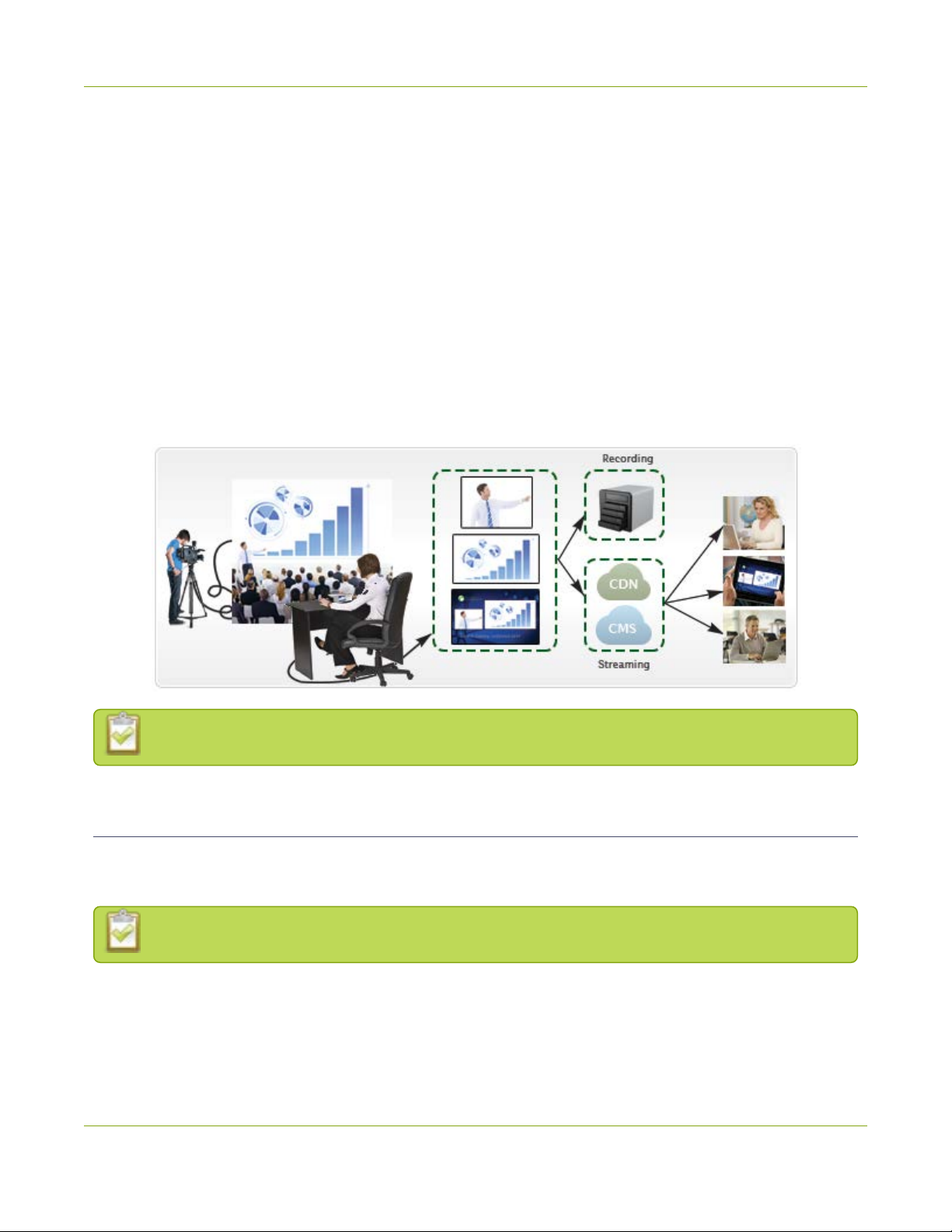
Pearl is a small, silent, portable live video production switcher. It supports live video streaming and recording,
capturing and streaming audio and HD video sources with resolutions up to 2048×2048. UsingPearl, you can
capture, record and stream computer monitors, radar displays, or anything that outputs to SDI, HDMI, DVI-I
(single link), VGA or component. Accompanying audio is supported via SDI, HDMI and TRS.
Simultaneously capture four audio visual sources and choose how you want to record and stream them. Keep
them separate, configure them in multi-source layouts for live switching, or do both!
The resulting streams can be viewed a number of ways through media players, browsers, on mobile devices
and through Content Distribution Networks (CDNs). Recorded files can be downloaded via FTPor set to
automatically upload via FTP, RSYNC, or CIFS and can be integrated into your Content Management System
(CMS).
Pearl does not capture from HDCP encrypted sources.
AV inputs
Pearl supports the following AVinputs directly. Nearly every other AV input is supported provided you have
the correct converter or adapter.
When using Pearl it is recommended you use a maximum of four simultaneous input sources.
3
Page 17
Pearl User Guide What's in the Box?
Table 1 Inputs for Pearl
SDI
SDI
2
* Pearl only captures video and audio from HDMIsources if the content is not HDCP-protected.
Audio
(Linear PCM)
ü
HDMI™ /
DVI-I (single link)
2
HDMI
Audio
(Linear
PCM)
ü
VGA
2 2
Left/Right TRS
Audio
(Balanced or
Unbalanced)
What's in the Box?
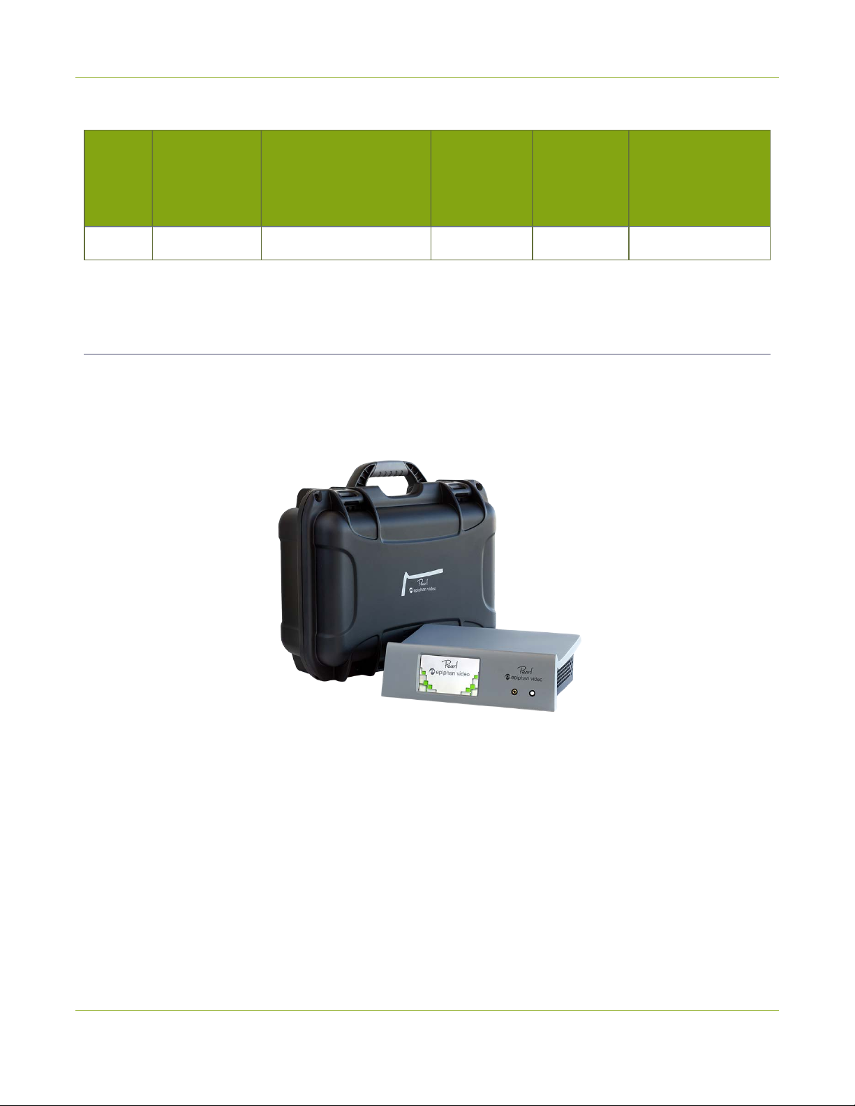
Pearl is a compact, portable system weighing only 3.4 lbs ( 1.54 kg) and measuring 187 mm (D) × 270 mm (W)
× 82 mm(H) (7.4” × 10.6” × 3.25”).
Pearl is shipped in a hard shell case that you can re-use for storing or moving Pearl between jobs.
Inside the hard shell case, under the foam tray you'll find the power cable and the following items:
1. One SDIcable
2. One HDMI cable
3. One VGAcable
4. One DVI(male) to HDMI(female) adapter
5. One Ethernet cable
4
Page 18
Pearl User Guide Front and back view
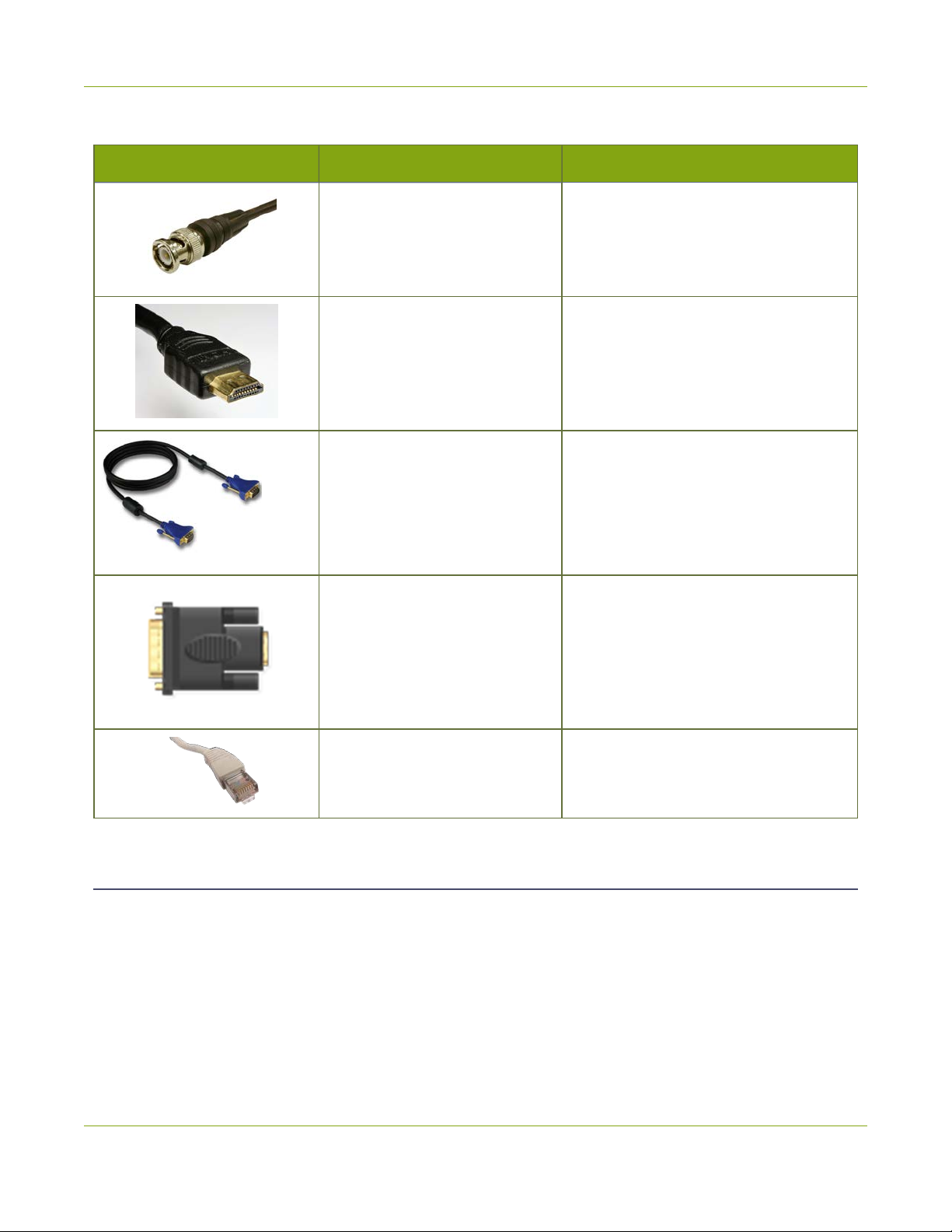
Table 2 Description of Included Cables (images for identification only, color and appearance may vary)
Image Name Description
SDIcable
HDMI cable
VGA Cable
DVI (male) to HDMI(female)
adapter
Connects SDI sources to Pearl's SDI
ports.
Connects HDMI or DVIsources to
Pearl's HDMI ports.
Connects VGA (or Component, if used
with a converter) signals to Pearl's VGA
ports.
Connects DVI sources to Pearl. Connect
the adapter to the output on your
screen or device, then connect the
provided HDMI cable to the adapter
and one of the HDMI ports on Pearl's
back panel.
RJ-45 Ethernet cable Connects the system to your network.
Front and back view
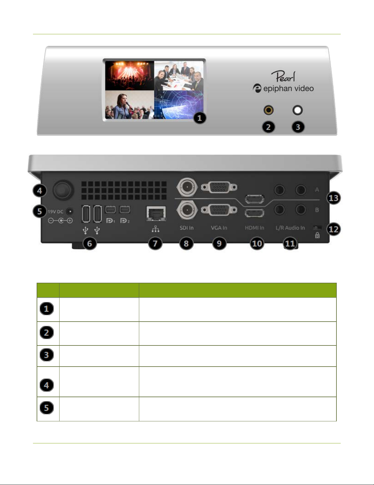
Pearl's front panel has the power indicator light, audio monitor jack and touch screen display for confidence
monitoring and simple configuration. The rear has an array of familiar computer connections. See below for a
complete listing of Pearl's physical features.
5
Page 19
Pearl User Guide Front and back view
Table 3 Pearl Front and Back Panel Descriptions
Label Name Description
Touch screen front panel
display
3.5 mm audio jack
Power light Glows when the system is powered on.
Power Button
Power jack
Used for confidence monitoring and simple configuration such as
obtaining system information and starting/stopping recordings.
For audio confidence monitoring. Plays the audio for the currently visible channel
Press to turn on; press and release to initiate a graceful system shutdown.
The power supply is plugged in here. The port requires a 19 Vcenterpositive DC power source. Alway use the provided power supply.
6
Page 20
Pearl User Guide Tech specs
Label Name Description
USB2.0 Ports
RJ-45 Ethernet Auto-sensing gigabit Ethernet 10/100/1000 Base-T network port.
SDI in Connects SDIsignals toPearl.
VGA in Connects VGA and other analog video signals toPearl.
HDMIin Connects HDMI and DVIsignals to Pearl.
TRSAudio in Connects balanced or unbalanced(line) left/right TRS audio to Pearl.
Lock
Row A/B designators
For connection of external hard drives, flash drives, or control interfaces.
Allows Pearl to be locked to a desk or surface using a laptop lock
cable.
This manual and Pearl's web admin interface refer to row A and row B.
Ports above the line are part of row A, ports below form row B.
Tech specs
This table outlines the technical specifications for Pearl. Go to www.epiphan.com/pearl to get the most recent
product specifications and additional information about Pearl.
Table 4 Specifications for Pearl
(2) SDI
Connectors
Resolutions
Video Inputs
HDVideo Format
Options
(2) HDMI™ / DVI¹
(2) VGA / Component²
VESA modes: 640×480 to 2048×2048 (or 2650×1600);
Custom HDMI/VGA/DVI/SDI modes up to 1920x1200
3G-SDI; HD-SDI; SD-SDI;
DVI single link;
HDMI;
R, G, B plus separate HSync and VSync signals;
R, G, B plus CSYNC signal;
7
Page 21

Pearl User Guide Tech specs
R, G, B with Sync-on-Green synchronization
(2) ¼" left/right TRS audio (balanced; or line/unbalanced)
Audio Input Connectors
SDI audio
HDMI audio
Connectors
Video Output
Built-In Display
Audio Output 3.5 mm audio Front-mounted jack for confidence monitoring
Built-in Display
Video Encoding
Front touch screen display for live switching, confidence monitoring, quick configuration, system information and recording control
Video Codecs H.264, MPEG-4, Motion JPEG
Video Bit Rates 100 - 9,999 kbit/sec
Key Frame Intervals Programmable
Color Resolution 4:2:0
Output Frame Size Configurable up to 3840x2160
Frame Rates
(per output stream)
(2) Displayport (software selectable content)*
(to be implemented in a future release)
Front touch screen display used for system information,
confidence monitoring and recording control
60 fps at 1920×1080 capturing and streaming 2 sources
simultaneously
30 fps at 1920×1080 capturing and streaming 4 sources
simultaneously
Audio Encoding Audio Codecs
Encoder Bitrate Sample Frequencies
MP3 64-192 kbps 22 kHz, 44 kHz, 48 kHz
PCM - 22 kHz, 44 kHz, 48 kHz
AAC 64-192 kbps 16 kHz, 22 kHz, 44 kHz, 48 kHz
8
Page 22

Pearl User Guide Tech specs
Connector 10/100/1000 Ethernet RJ45
Streams MPEG-TS, FLV, ASF and MJPEG
RTSP over TCP/UDP
Publish to Streaming Server / CDN(RTSP, RTMP)
IPNetwork Interfaces
Multicast Streams RTP, MPEG-TS &RTP and MPEG-TS over UDP
HLS - Native Apple HTTP stream for iPad, iPhone and iPod
Touch
Video / Audio Recording
and File Management
Network Discovery /
Announce
Internal Storage
Local Storage
Network Storage
Playback and Recorded Formats
Web UI for full administration. On-screen display and mobile UI for confidence
monitoring and simple administration.
UPnP, SAP
1 TB³
Automatically removes oldest recordings from internal
storage as space is required.
File maintenance through admin interface (Web UI)
Automatic or manual copy to local USB drives via the (2)
USB 2.0 ports
FTP server and FTP client capabilities (automatic and
manual)
Download recorded videos (AVI, MOV, MP4or MPEG-TS)
using the Web UI and playback through any compatible
player.
Administration
Time Synchronization NTP, TIME (RFC 868), PTP v1 (IEEE-1588-2002 V1)
Product Dimensions 10⅝" x 3¼" x 7⅜" (270mm x 82mm x 187mm)
Product Weight 3.4 lbs (1.54kg)
Multiple user accounts/passwords.
Included API for integration into existing environments (executed via HTTP or
RS-232). RS-232 API integration requires a USB to RS-232 adapter (not
included).
9
Page 23

Pearl User Guide Tech specs
Country of Origin Made in North America (Canada)
¹Using HDMI port, with the supplied adapter
²Requires component to VGA adapter (not included)
³The Internal 1TB HDD provides approximately 900GB of space for recording. Recording space can be
virtually unlimited with the use of networked storage.
10
Page 24

Pearl User Guide Quick start
Quick start
This section helps you get up and running quickly with your Pearl.
Before you get started, make sure you have:
l a video source (i.e. a camera, a computer, a tablet, or a phone) (for SDIand HDMI, the source must not
be HDCPprotected)
l for SDI orHDMI sources, accompanying audio over the same source cable
l the appropriate cables or adapters to convert the output to SDI, HDMI or VGA (if needed)
l optionally, a separate TRS audio source such as a microphone
l ideally, a network with Dynamic Host Configuration Protocol (DHCP)
l a computer with a web browser connected to the same network (this is referred to as the “admin”
computer in the steps below)
These instructions include steps for setting up and configuring audio. Skip these optional steps if
you do not want to configure an audio source at this time.
Pearl is pre-configured with two plug and play channels: Auto A and Auto B. This quick start uses these
channels to get you streaming and recording as soon as possible.
Get started quickly with auto channels:
1. Turn on your HD source and connect the output cable to a port in Row A on the back of Pearl (if
needed, use an adapter such as the DVI to HDMI adapter).
2. If desired, plug a second source into one of the Row B inputs on the back of the system.
3. (optional) Attach a set of left/right TRS audio cables from your audio source to the TRS audio input
ports on the back of Pearl.
4. Connect the Ethernet cable to the Pearl. Connect the Ethernet cable to your network.
5. Attach the power cable to the system and plug it into a power source.
6. Press the power button on the back panel to turn on the system.
7. Wait for the Pearl to complete the power up sequence. The system is ready a few moments after the
power LED illuminates.
8. (optional) Plug speakers or headphones into the 3.5 mm audio jack at the front ofPearl.
The system automatically configures the channel's frame size to match the source resolution and calculates
the best bit rate for the default frame rate of 30 fps.
11
Page 25
Pearl User Guide Quick start
Pearl's front screen, if enabled (it is enabled by default, see Configure the touch screen), updates to show you
previews of your channel(s) for confidence monitoring. Use your speakers or headphones to verify audio
quality and levels.
In release 3.15.1 your channel will not automatically have audio. Audio is added in the following
steps.
To view the auto channels:
If you don't want to add audio to your channel, you're done with configuration!
You can start viewing the channel(s) immediately by using a browser on a computer on the same network.
1. Find the system’s IP address: from a single channel view or grid view, touch the system settings (gear)
button then touch System Status.
2. Open a browser window on a computer on the same LAN or network
3. Browse to one of the following URLs:
For Auto A:http://<IP Address for Pearl>/preview.cgi?channel=1
For Auto B: http://<IP Address for Pearl>/preview.cgi?channel=2
For example:http://192.168.0.183/preview.cgi?channel=2
12
Page 26
Pearl User Guide Quick start
You'll find alternate connection streams (i.e. RTSPor MPEG-TS) for these channels by logging into the admin
interface and accessing Auto A and Auto B by the links under the Channels menu. See What is streaming?
Configure audio
Pearl is managed from a web interface. This interface acts as a configuration utility and system monitor.
You can access the web interface via either the device's IP address on your network, via DNS-based discovery
if you have Bonjour services installed, or via a static recoveryIPaddress. This quickstart uses the IP address
method. You can follow other discovery methods described in the section Connect to the admin interface.
Connect to the admin interface:
1. Find the system’s IP Address:
l from a single channel view or grid view, touch the system settings (gear) icon then touch
System Status; or
l if your system doesn't have any channels showing, touch the screen anywhere to move to the
system settings screen then touch System Status.
2. Type the following string into the address bar of your web browser on your admin computer (where <ip
address> is the ip address of your Pearl):
http://<IP address of Pearl>/admin
For example: http://192.168.0.183/admin
3. Enter the user name and password then click OK. The administrative user is ‘admin’. Initially no
password is set. To set a password follow the procedure outlined in User administration.
13
Page 27
Pearl User Guide Quick start
Add audio to the channel's sources list
Channels expose your sources to your streaming users and prepare the sources for recording. Your auto
channel already has the video source added - you need only add the audio source of your choice.
To add audio to your channel:
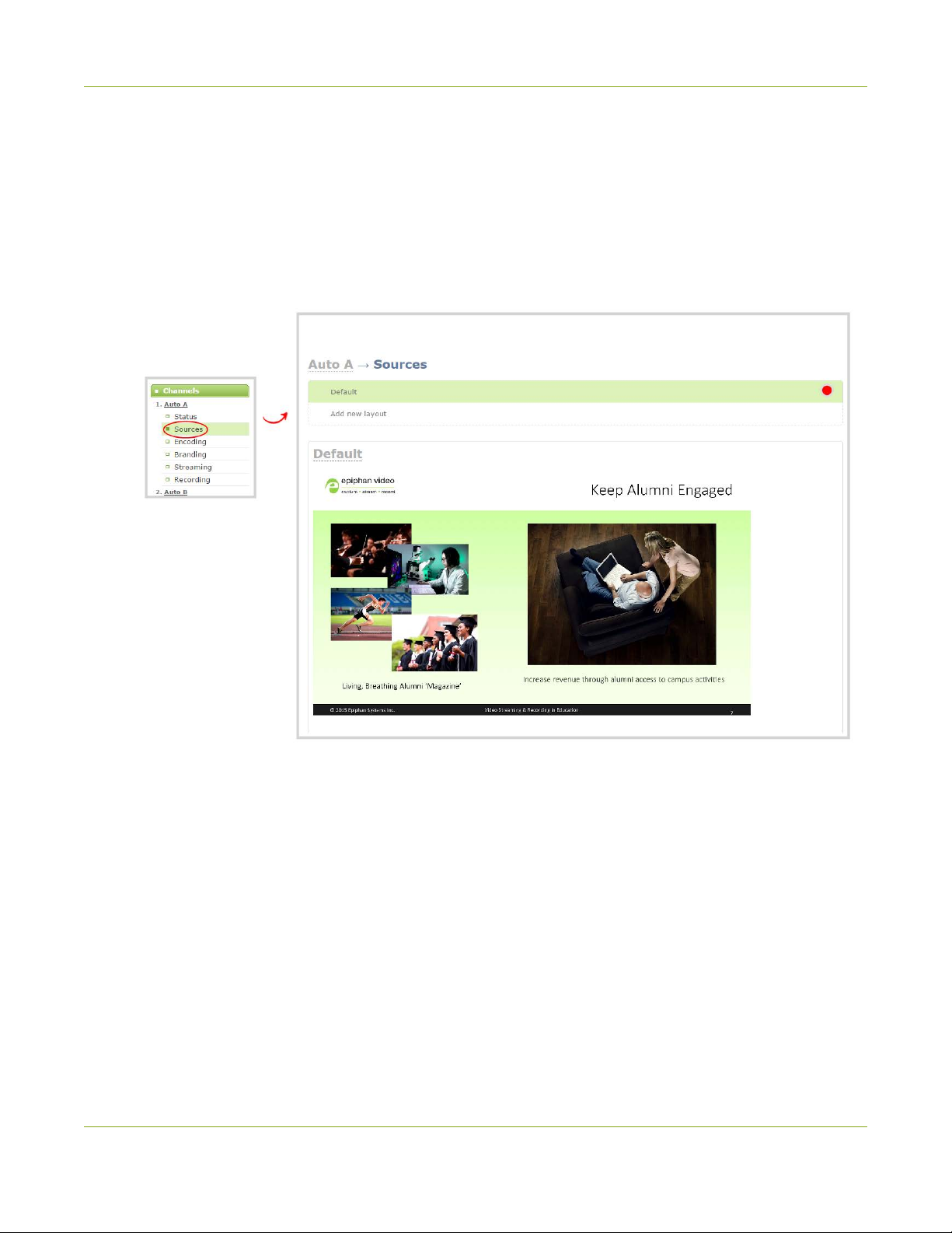
1. In the web interface, click the Auto A channel; the channel expands.
2. Click Sources; the sources configuration page opens.
3. You're automatically editing the Default layout in the channel layout editor.The Auto-A source is
previewed in the layout area.
4. Scroll down and choose an audio source from the displayed list.
5. Scroll down and click Save at the bottom right of the screen to save your changes.
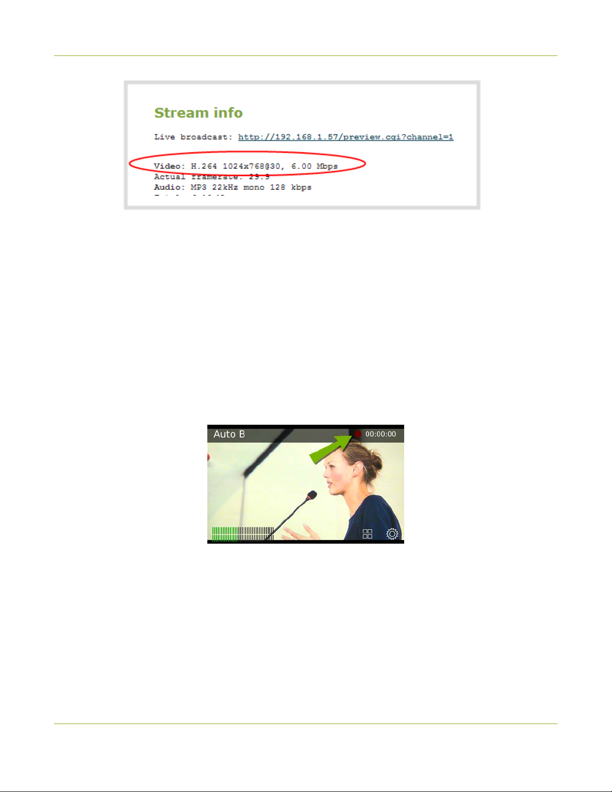
6. Click Status for your channel.
7. Notice the Stream Info section has an item named Video that reflects your channel's settings (the
frame rate is specified as <resolution size>@30 for 30 frames per second). It also provides an indication
of the current actual frame rate.
14
Page 28
Pearl User Guide Quick start
Record the Channel
The channel is set up and streaming. This may be all you need, but if you like, you can also record the stream.
You can choose to initiate and control channel recording from either the touch screen or the web interface.
To control recording from the touch screen:
1. If viewing the grid view, touch the channel for which you wish to control recording; the channel view is
displayed.
2. If necessary, touch the screen once to display the controls for the channel.
3. Touch the recording control button; the touch screen will start a timer to indicate the length of the
recording. Touch the control again to stop recording. (If the button is not visible, recording control via
the touch screen is not enabled; see Configure the touch screen.)
To control recording from the web interface:
1. From the web interface, scroll to the Channels section.
2. Click Recording for your channel; the Recording page is displayed.
3. Click the red Start button; the text at the top of the screen changes to indicate the recording is
starting, then indicates the length of time since the recording started.
4. Click the black Stop button; the recorder stops.
15
Page 29

Pearl User Guide What’s Next?
5. Refresh the page by clicking Recording again; the page reloads and a file list appears that shows your
newly recorded stream snippet.
6. Click the file name to download and view your recording.
What’s Next?
Now that you have a source setup and ready to stream, you can fine-tune the system to your exact
requirements. You can look at topics such as:
l Create a simple channel
l Create a custom channel
l Live video mixing / switching
l What is streaming?
l File and recording transfer
l User administration
When you have completed system tuning, make sure to back up the system configuration using the
procedure described in:
l Save and restore device configuration
Refer to the table of contents for a complete list of the topics covered.
16
Page 30

PART 1:
If you followed through the quick start guide, you already have a basic configuration and possibly a recording
of an input. Before you tweak the channel or configure more, this part of the manual helps you to get your
Pearl properly configured for your network.
Topics covered:
l Connect to the admin interface
l Configure the touch screen
l User administration
l View system information
l Configure network settings
l Configure date and time
l Configuration presets
l Restrict viewers by IPaddress
Setup
17
Page 31

Pearl User Guide The admin interface
The admin interface
Pearl is managed from a web interface. This means to perform administrative tasks with Pearl you use an
internet browser on a PC (or laptop, or tablet) connected to the same local Ethernet network.
Connect to the admin interface
If you know the IP address of the system you may type it into the address bar of your web browser.
http://<IP Address of Pearl>/admin
However if this is the first time you access your system, you likely don't know the IPaddress, so you can use
one of the following connection methods:
For networks with DHCP use one of the following procedures:
l Connect using the touch screen
l Connect via DNS-based service discovery
l Connect via the Epiphan discovery utility
For networks without DHCP, use the following procedure:
l Connect via persistent static IP address
You can also connect to a reduced Operator tablet interface. See Connect to the tablet
interface.
Connect using the touch screen
To connect to the web admin interface, you need to know your Pearl's IPaddress. There are a number of ways
to determine the IP addreds, but the simplest way is to use the touch screen, if it is enabled.
To connect to the web admin interface using the touch screen to determine the IP address:
1. Obtain the IP address using the touch screen:
l from a single channel view or grid view, touch the system settings (gears) button then touch
System Status; or
l if your system doesn't have any channels showing, touch the screen anywhere to move to the
system settings screen then touch System Status.
18
Page 32

Pearl User Guide Connect to the admin interface
2. Type the following string into the address bar of your web browser on your admin computer (where <ip
address> is the ip address of your Pearl)
http://<ip address>/admin
For example: http://192.168.1.163/admin
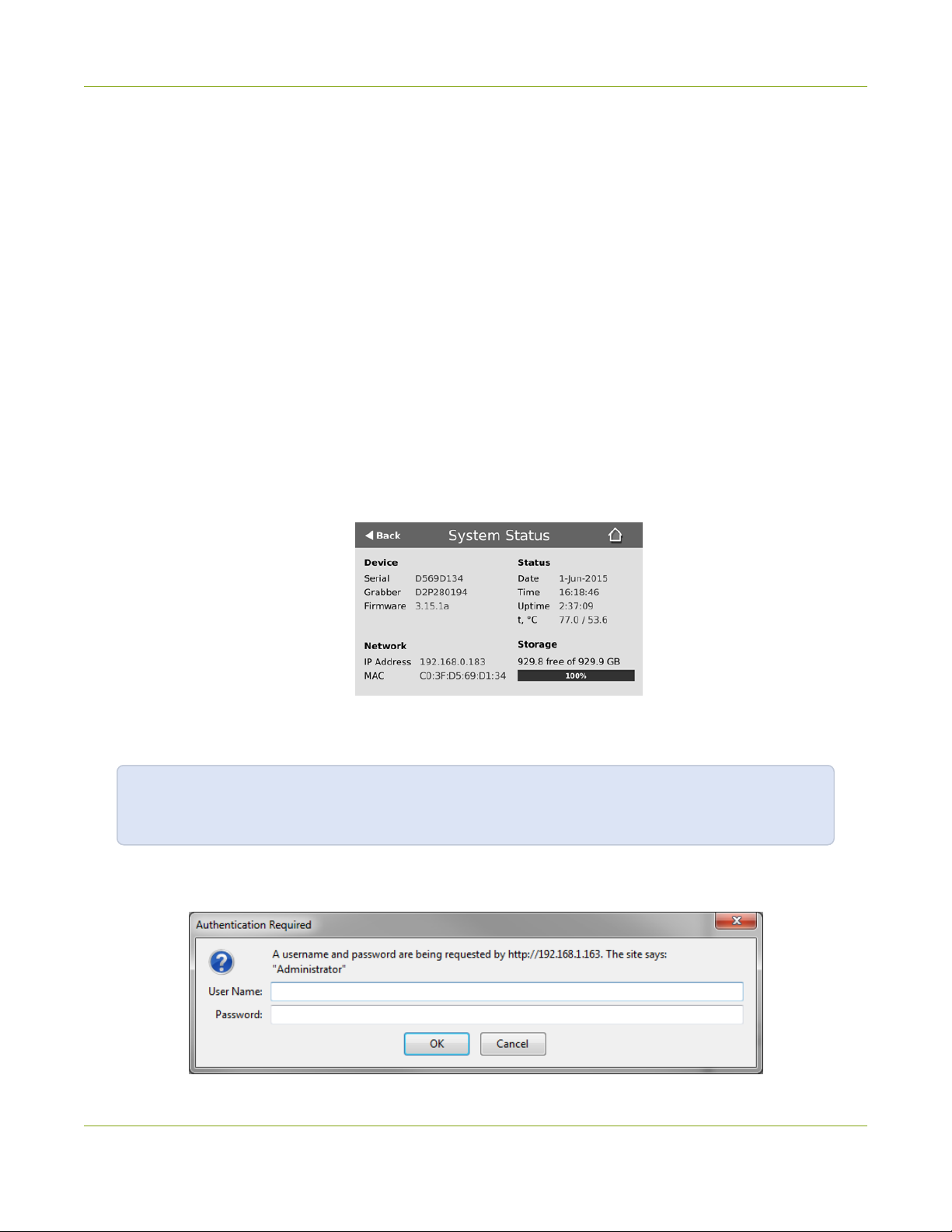
3. Enter the user name and password then click OK. The administrative user is ‘admin’. Initially no
password is set. To set a password follow the procedure outlined in User administration.
Connect via DNS-based service discovery
Pearl uses DNS-based messages to advertise details about itself, including its host name. With a compatible
utility installed on your computer, you can access the system simply by typing its serial number and the suffix
“.local” into the address bar of your browser.
To ensure you have compatible software, refer to the following table.
Table 5 Installing Bonjour Print Services
System Action Needed
You must install Bonjour Print Services:
1. Use the following URL - http://support.apple.com/kb/DL999
Microsoft Windows
2. Click Download.
3. Follow the system prompts to download and install the application.
19
Page 33

Pearl User Guide Connect to the admin interface
System Action Needed
MacOSX
Linux
To access Pearl's web interface via DNS service discovery:
1. Find the system’s serial number. It is printed on a sticker on the back of the system, or available on the
system information display on the touch screen. To access the serial number:
l from the "no channels" screen, touch the screen anywhere to move to the system information
screen;
l from a single channel view, touch the system information button; or
l from the grid view, select a channel, then touch the system information button.
2. Type the following string into the address bar of your web browser on your admin computer (where
<serial> is the serial number of your Pearl):
http://<serial>.local/admin
For example: http://95dd40d5.local/admin
The Bonjour software used for service discovery is built into the Mac OS. No special
actions are needed.
The Avahi implementation used for DNS-based discovery is shipped with most Linux
distributions. If necessary, check with your administrator to ensure you have the
Avahi package installed.
3. Enter the user name and password then click OK. The administrative user is ‘admin’. Initially no
password is set. To set a password follow the procedure outlined in User administration.
20
Page 34

Pearl User Guide Connect to the admin interface
4. Optionally, navigate to the Network link under the Configuration heading and note the IP address of
the system.
Connect via the Epiphan discovery utility
Epiphan provides a utility for discovering Epiphan systems on your network. The Epiphan network discovery
utility is a 32-bit Windows executable that works on most 32-bit and 64-bit Windows operating systems.
Download and install the utility via this link: http://www.epiphan.com/downloads/NetworkDiscovery.exe.
To access the Pearl's web interface via the Epiphan discovery utility:
1. Launch the discovery utility.
2. Click Search to find all the Epiphan systems on the network; a list similar to the following appears.
3. If more than one system appears, select the one you wish to configure by matching the serial number
listed with the serial number marked on the back of the system.
4. Optionally, note the IP Address shown in the stream properties. Use this for quicker access to the
system on future configuration sessions.
5. Click the Web config button; your browser will open and point to the web interface page.
http://<IP Address for Pearl>/admin
21
Page 35

Pearl User Guide Connect to the admin interface
6. Enter the user name and password then click OK. The administrative user is ‘admin’. Initially no
password is set. To set a password follow the procedure outlined in User administration.
Connect via persistent static IP address
Your Pearl has a default persistent static IP address, also known as the recoveryIPaddress. If ever you need
to set it up on a network that does not support DHCP, or you need to recover from a previous static IP
address setting, you can use this method to connect directly to the system for configuration.
To perform this procedure you will need a workstation computer for which you are able to modify network
settings.
Pearl is pre-configured with the following static address defaults:
l IP Address: 192.168.255.250
l Netmask: 255.255.255.252
l Username: admin
l Password: your admin password (by default set to no password)
To access Pearl's web interface via the persistent static IP address:
1. Establish an Ethernet connection between Pearl and the workstation by one of the following methods:
a. Connect the system to a local Ethernet network shared with the workstation.
b. Connect the system directly to the workstation’s Ethernet port using either a regular or a
crossover Ethernet cable.
2. Record the network settings of the workstation being used to connect to Pearl so that they can be
restored later.
3. Temporarily change the network configuration on the workstation to the following:
a. Use Static IP assignment
b. IP address: 192.168.255.249
c. Subnet mask: 255.255.255.252
22
Page 36

Pearl User Guide User administration
4. Start a web browser on the workstation and browse to: http://192.168.255.250/admin/
5. Log in as the administrator user with the user name admin and the admin password (by default there is
no password); the web interface page opens.
6. Click the Networking link in the Configuration menu.
7. Select the radio button to use a static address and configure the system with a static IP address and
network settings relevant to the network being used. For specific details about the settings presented,
see Configure network settings.
8. Restore the previously saved network configurations on the workstation.
User administration
Pearl has three configured users:
l admin
l operator
l viewer
By default, none of these users have passwords. For security purposes you should add passwords to the
admin and operator accounts.
This section describes the following user administration topics:
l User types and privileges
l Set or change user passwords
l Remove user passwords
l Overcome lost passwords
l Configure LDAP
l Change the logged-in user
l Restrict viewers by IPaddress
User types and privileges
Pearl's three user accounts are admin, operator and viewer. The user account names cannot be changed and
the accounts cannot be disabled. By default, none of the accounts have passwords.
Admin
The admin account is the main operator used for all system configuration. This user has access to all options
in the web interface.
23
Page 37

Pearl User Guide User administration
Operator
The operator account is a subclass of the admin account. The operator can log in and view all configuration
items but may only make changes to a small number of options. This account is intended for an operator to
start and stop recordings, download recordings, or perform network diagnostics.
Viewer
The viewer account is for all end-users who are permitted to view the streamed channels. By default, when
there is no password, users are not prompted for a username and password when viewing a channel. The
viewer username and password prompt appears only when there is a viewer password set.
In addition to the global viewer account, each channel can set a viewer password that overrides the global
value. See What is streaming?.
Current User
When logged in to the web interface, the current username is displayed at the top right corner of the screen.
User Privileges
The following table outlines the privileges for each user:
Table 6 User Privileges in the Web Interface
Action or Menu Option viewer operator admin
View channel output
Channel Operations
View Channel Configuration
Rename a Channel
Configure Stream Channel
Configure Stream Sources
Publish a Stream
Configure Branding for a Channel
Start the Stream Recorder
ü ü ü
ü ü
ü
ü
ü
ü
ü
ü ü
24
Page 38

Pearl User Guide User administration
Action or Menu Option viewer operator admin
Stop the Stream Recorder
View Recorded FilesList
Download RecordedFiles
Delete RecordedFiles
Source Operations
View Source Configuration
Rename Source
Configure Source
View Source Snapshot
SystemConfiguration Operations
View System Configuration
Configure Automatic File Upload
Select External USBDrive Behavior
ü ü
ü ü
ü ü
ü ü
ü ü
ü
ü ü
ü ü
ü ü
ü
ü
Configure FTPServer
Configure UPnP Sharing
Configure Network Address
Configure USBTethering
Perform NetworkDiagnostics
Configure Date andTime preferences
Set or Change User Passwords
Configure the Touch Screen
Configure SerialPort Flow Control
Upload Branding Images
Upload Branding Templates
ü
ü
ü
ü
ü ü
ü
ü
ü
ü
ü
ü
25
Page 39

Pearl User Guide User administration
Action or Menu Option viewer operator admin
Select BrandingTemplate
Enable Remote Support
Backup Device Configuration
Restore DeviceConfiguration
RestoreFactoryConfiguration
Reboot Device (via Web Interface)
Shutdown Device (via Web Interface)
Configure Time Until Next DiskCheck
Perform DiskCheck
View DiskInformation
Upgrade Firmware
View System Information
ü
ü
ü
ü
ü
ü
ü
ü
ü
ü ü
ü
ü ü
Set or change user passwords
By default, admin, operator and viewer have no assigned passwords. Both the admin and the operator user
have access to the web admin interface, so you should always set a password for both admin and operator
accounts. Refer to your system administrator for your organization’s specific password requirements.
In addition to setting global passwords for viewers, you can also set access passwords and IPrestrictions on a
per-channel basis from the channel's Streaming page. See What is streaming?Restrict viewers by IPaddress.
Passwords are case sensitive and can use all alpha-numeric keys in the ASCII range. Your password can be up
to 255 characters long, but should not include any spaces.
Setting a user’s password causes the user to be logged out. Be ready to log back in with the new
admin password or have operators and viewers log in with the appropriate new password.
Viewers may need to refresh their browser window or press play in their media player.
If you lose the admin password, refer to the section Set or change user passwords.
To set a user password:
26
Page 40

Pearl User Guide User administration
1. Connect to the admin interface using your preferred connection mechanism. See Connect to the admin
interface.
2. Login as admin.
3. Select the Access passwords link in the Configuration menu; the password configuration page opens.
4. Highlight and delete the current password for your selected user (the password is currently masked
as dots).
For security reasons, the current password appears as eight dots regardless of password
length, and even if there is no password set.
5. Highlight and delete the confirmation password for the selected user.
6. Select the user’s password field and type a new password for the user.
The new password must have between 1-255 alpha-numeric characters or special
characters with no spaces. Passwords are case sensitive.
7. Select the user’s password confirmation field and confirm the new password.
8. Click Apply.
9. If you were logged in as the user whose password you just changed, you are logged out and must log
back in with the new password. If you added or changed the viewer’s password, all viewer’s stream will
pause until they log in with the new password.
If desired, you may specify multiple account passwords on the same page before clicking Apply.
Remove user passwords
If you want to remove passwords for one or more user accounts, you may do so via the web interface. If you
don’t remember the admin password, refer to the section Overcoming Lost Passwords.
Note that viewer passwords can be set on a per-channel basis.
Clearing a user’s password will cause that user to be logged out. Be ready to log back in with the
new admin password. If viewers are watching the broadcast when the viewer password is cleared
they will be logged out. Viewers may need to refresh their browser window or press play in their
media player to trigger the login prompt.
To clear a user’s password:
27
Page 41

Pearl User Guide User administration
1. Connect to the admin interface using your preferred connection mechanism. See Connect to the admin
interface.
2. Login as admin.
3. Select the Access passwords link in the Configuration menu; the password configuration page opens.
4. Highlight and delete the current password for your selected user (the password is currently masked as
dots).
For security purposes, the current password appears as eight dots regardless of password
length, and even if there is no password set.
5. Highlight and delete the confirmation password for the selected user.
6. Click Apply.
7. If you were logged in as the user whose password you just cleared, you are logged out and must log
back in without a password. If you cleared the viewer’s password, all viewers’ stream will pause until
they log in without a password.
To clear a user’s password on a specific channel:
1. Connect to the admin interface using your preferred connection mechanism. See Connect to the admin
interface.
2. Login as admin.
3. Click the Streaming link for the channel; the channel's Streaming configuration page opens.
4. From the Access control section do one of the two following things:
a. clear the viewer password field; or
b. select Use global settings from the access control drop down.
5. Click Apply.
Overcome lost passwords
If you have lost the password for the operator or viewer account, you can log in to the web interface as admin
and reset the password using the procedure described in Overcome lost passwords.
If you have lost the admin password and you have remote support enabled on the system, you can contact
Epiphan support to request a remote password change. See Support. If remote support is disabled, you will
need to return the system toEpiphan for password recovery. Contact Epiphan support to discuss this option.
28
Page 42

Pearl User Guide User administration
Configure LDAP
You can use the Lightweight Directory Access Protocol (LDAP) for authentication into the system. Specify user
roles by using group DNs for users who log in as the administrator, operator, or as a viewer.
The system has only one admin user and one operator: LDAP users log in as either the admin or
operator, they do not have their own private profiles.
When enabled, LDAP authentication is an alternative to the regular system usernames and
passwords. You may still login as admin, operator or viewer using the passwords for those
accounts. Furthermore, any LDAPusers with the name admin, operator or viewer are ignored.The
local accounts are used instead.
For security reasons, you should configure passwords for the local accounts. See Configure
LDAP.
These instructions assume you have a pre-configured LDAP server. The server must support anonymous
binding or have a special bind account with search access priveleges. (Note that Active Directory does not
support anonymous binding.)
LDAP referrals, restrictions and failovers are not supported.
To configure LDAPauthentication for your Pearl:
1. Connect to the admin interface using your preferred connection mechanism. See Connect to the admin
interface.
2. Login as admin.
3. Select the Access passwords link in the Configuration menu; the password configuration page opens.
4. Scroll to the LDAPauthentication section.
29
Page 43

Pearl User Guide User administration
5. Click the Enable LDAPauthentication checkbox to enable LDAPauthentication (or uncheck to
disable).
6. Specify the server IPaddress and (optional) port for your LDAPserver(i.e. 192.168.1.101:389) in the
Server address[:port] field.
7. Use the Connection encryption drop-down to specify the type of encryption, if any used by your
LDAP server.
Connection
encryption
No Encryption No encryption is used to connect to the LDAP server. The default port is 389.
SSL SSL encryption is used to connect to the LDAP server. The default port is 636.
TLS/STARTTLS
8. Specify the fully qualified DN and password for LDAPbind in the BindDN and Bind password fields.
(The password masked as dots on the screen.) These fields are only needed if your LDAPserver does
not support anonymous binding.
9. In Base DN, specify the baseObject in which to search for entries. The system will search this object
and the whole subtree starting at the base DN.
10. By default the search attribute is uid, which is suitable for a unix environment. Specify a different value
in the Search attribute field, if needed. For Active Directory environments, specify
userPrincipalName. The value of this attribute must be unique in the BaseDN.
11. In the Administrators (group DN) field, specify the distinguished name of the group users must be
part of to be logged in as the administrator. Users must have the member or unqueMember attribute
for the specified group to be granted Administrator access.
If left blank, LDAP is not supported for Administrators(but can still be used for Operators and Viewers).
Description/Default port used
The connection is initially unencrypted then upgraded to TLS encryption is
used. The default port is 389.
30
Page 44

Pearl User Guide User administration
12. In the Operators (group DN) field, specify the distinguished name of the group users must be part of
to be logged in as the operator. Users must have the member or unqueMember attribute for the
specified group to be granted Operator access.
If left blank, LDAP is not supported for Operators (but can still be used for Administrators and Viewers).
13. In the Viewers (group DN) field, specify the distinguished name of the group users must be part of to
be logged in as a viewer. Users must have the member or unqueMember attribute for the specified
group to be granted Viewer access.
If left blank, LDAP is not supported for Viewers (but can still be used for Administrators and Operators).
14. Click Apply.
When a user of the LDAPserver next visits the admin or viewer page for the system, the system prompts for
use the username and password. For ActiveDirectory servers, the user needs to enter his fully qualified
username(i.e. username@domainname) in addition to his LDAPpassword.
Users are required to authenticate once to the system and one time per channel they view.
Therefore users see a prompt to log in to the system (the system name is shown) and a second
time to log in to the channel (the channel name is shown).
In one case, LDAPreplaces the local viewer account instead of working side-by-side with it.
When LDAPis enabled and the viewer account has no password (either there is no global viewer
password or the channel overrides the global password with a blank password), the viewer must
authentication withLDAP, he may not alternatively use the viewer account with a blank
password.
Change the logged-in user
When you log in to the web interface as admin or operator, your browser remembers this configuration and
automatically logs you in as the same user when you go back to the site.
Sometimes you need to change from operator to admin, or vice versa.
To change the logged-in user:
1. Exit your browser completely, open an incognito/private window in your browser, or open a different
browser (i.e. Internet Explorer, Chrome, and Safari are different browsers).
2. Connect to the admin interface using your preferred connection mechanism. SeeConnect to the admin
interface.
3. You are prompted for a username and password.
31
Page 45

Pearl User Guide User administration
Restrict viewers by IPaddress
Pearl permits you to restrict which computers can access broadcasts by building a list of allowed and/or
denied IP addresses. You can do this at a global level for the system and can also override these settings on a
per-channel basis. Both global and per-channel configuration procedures are described below.
IP address restriction is valid for the viewer only and does not affect the web admin interface or
the mobile configuration interface.
If your viewer account has a password, your viewers must connect to the system from a computer (or
gateway) with a permitted IP address and must also supply the username (viewer) and password before they
can view the broadcast.
To restrict access by IP address you need to know the IP addresses, or range of addresses for your viewers. By
default all IP addresses are allowed to connect to the broadcast.
If you’re not familiar with creating allow/deny lists, refer to the examples below this procedure for assistance
with crafting your lists.
To restrict viewers by IP address:
1. Connect to the admin interface using your preferred connection mechanism. See Connect to the admin
interface.
2. Login as admin.
3. Select the Access passwords link in the Configuration menu; the password configuration page opens.
4. Type allowed IP addresses or address ranges in the Allow IP’s field. Separate addresses with a comma.
5. Type denied IP addresses or address ranges in the Deny IP’s field. Separate addresses with a comma.
6. Click Apply.
To restrict viewers of a specific channel by IPaddress:
1. Connect to the admin interface using your preferred connection mechanism. See Connect to the admin
interface.
2. Login as admin.
3. Select the Streaming link for the desired channel; the streaming configuration page opens.
4. From the Access Control drop-down, select Use these Settings; local password and Allow/Deny IP
lists are enabled.
5. If desired, type a password for the viewer in the Viewer Password field.
6. Type allowed IP addresses or address ranges in the Allow IP’s field. Separate addresses with a comma.
32
Page 46

Pearl User Guide User administration
7. Type denied IP addresses or address ranges in the Deny IP’s field. Separate addresses with a comma.
8. Click Apply.
If a user attempts to connect to the stream from a disallowed IPaddress, access is denied. If connecting by
internet browser, the message "IPaddress rejected." is displayed.
The following table describes the applicable fields.
Table 7 IP Based Restriction Fields
Label Description/Options
Enter individual IP Addresses or IP Address ranges, separated by commas. To specify a
range, use a hyphen (-). Optional spaces improve readability.
Users connecting from addresses in this list are permitted to view broadcasts from the
Allow IP's
system, provided their IP address is not in the Deny IP’s list.
To allow all (except IP addresses in the deny list, if any), leave the field blank.
You can use the Allow list by itself, or in conjunction with the Deny IP’s list as an exception
to a rule in the allow list.
Enter individual IP Addresses or IP Address ranges, separated by commas. To specify a
range, use a hyphen (-). Optional spaces improve readability.
Users connecting from addresses in this list are not allowed to view broadcasts from the
Deny IP's
system, unless their IP address is in the Allow IP’s list. If a specific IP address is in both lists,
access to the stream is denied.
You can use the Deny list by itself, or in conjunction with the Allow IP’s list as an exception
to a rule in the allow list.
IPRestriction Examples
Allow List with Distinct IP Addresses
The simplest allow/deny list is to use the list of known IP addresses to craft a list of allowed IP addresses. All
other addresses are denied access to the broadcast.
For example if your system is accessible on your local area network (LAN) and you want to make sure only the
CEO’s specific desktop, laptop and tablet computers (with IP Addresses 192.168.1.50, 192.168.1.51, and
192.165.1.75, respectively) can connect to the broadcast, construct the following allow list:
Allow: 192.168.1.50, 192.168.1.51, 192.168.1.75
33
Page 47

Pearl User Guide User administration
Allow List with a Range of IP Addresses
Sometimes you’ll want a range of computer IP addresses to connect to your system. This may happen when
you have one range of IP addresses assigned to desktop computers (i.e. in the range 192.168.1.1 to
192.168.1.100) and another range assigned to boardroom computers (i.e. the range 192.168.1.200 to
192.168.1.250). If you only want the boardroom computers to connect to broadcasts from the system you
can specify the range of boardroom IP addresses rather than needing to type in each individual address. The
allow list looks as follows:
Allow: 192.168.1.200-192.168.1.250
Note that we could have specified two of the IP addresses in the previous example as a range.
Allow List with a Range of IP Addresses and One or More Specific IP Addresses
Putting the first two examples together, we want to permit access to IP addresses in the range of boardroom
computers (192.168.1.200-192.168.1.250) and also want to add the desktop, laptop and tablet computers
of the CEO (IP addresses 192.168.1.50, 192.168.1.51, and 192.168.1.75, respectively). Note the first two IP
addresses are consecutive, so they can be added as a second range. Add these IP addresses to the list as
follows:
Allow: 192.168.1.200-192.168.1.250, 192.168.1.50-192.168.1.51, 192.168.1.75
Your list can have multiple ranges and multiple distinct IP addresses, provided they are separated by commas.
Deny List with Distinct IP Addresses
Another simple allow/deny list is to use the list of known IP addresses to list specific denied IP addresses. All
other addresses are allowed access to the broadcast.
For example imagine your system is accessible on your local area network (LAN) and you want to allow any
computer on the LAN can access the stream except your publicly-accessible boardroom (with IP address
192.168.1.211). You can use the following deny list (leave the allow list empty) to permit all computers except
the boardroom computer:
Deny: 192.168.1.211
As with Allow lists, your deny list can specify a range of IP addresses, and can specify multiple ranges or
distinct IP addresses in a comma-separated list.
34
Page 48

Pearl User Guide User administration
Allow List with a Range of IP Addresses, Distinct IP Addresses, and an Exception
Building on the previous examples, consider the situation where you want the CEO’s computers
(192.168.1.50, 192.168.1.51, 192.168.75) and all boardroom computers (192.168.1.200-192.168.1.250)
to access the broadcast, with the exception of the public boardroom computer (192.168.1.211). Use both
allow and deny lists to create the rule as follows:
Allow: 192.168.1.200-192.168.1.250, 192.168.1.50-192.168.1.51, 192.168.1.75
Deny: 192.168.1.211
Both lists can have multiple ranges and multiple distinct IP addresses, provided they are separated by
commas.
Deny List with a Range of IP Addresses
Converse to the previous examples, consider the situation where you want every computer on the network to
access the broadcast, with the exception of the CEO’s desktop, laptop, and tablet computers. Additionally,
boardroom computers should not be permitted with the exception of the cafeteria computer (IP address
192.168.1.222).
The deny list is an "exception" list for the allow list. So to craft the rule described above we need to allow all the
computers in the local subnet, then deny specific sub-ranges including two groups of boardroom computers
ensuring the cafeteria computer's IP address is not in the deny list:
Allow: 192.168.1.1-192.168.1.250
Deny: 192.168.1.200-192.168.1.221, 192.168.1.223-192.168.1.250, 192.168.1.50-192.168.1.51,
192.168.1.75
35
Page 49

Pearl User Guide Pearl's touchscreen
Pearl's touchscreen
Pearl's front panel includes a touch screen display used for confidence monitoring and basic configuration.
Use the touch screen to view system information, configure network settings, load configuration presets, view
configured channels, review audio levels, and control channel recording.
By default, the screen and all its features are enabled. You can configure whether or not the touch screen is
active and which features are enabled. See Configure the touch screen.
Pearl's touch screen is capacitive. Use your finger or a specially designed soft-tipped capacitive
stylus with firm but gentle pressure. Pressing too hard or using something other than a fingertip
or capacitive stylus can result in damage to the screen.
This section describes how to use the touch screen and provides an overview of the functionality available
through the screen.
l Touchscreen overview
l View system information
l Channel monitoring
l Pearl's audio jack
l Control recording
l Configure the touch screen
Touchscreen overview
While Pearl is booting, the following image appears on the touch screen (if the screen is enabled).
After boot up is complete, Pearl displays a grid view providing an overview of all configured channels.
36
Page 50

Pearl User Guide Touchscreen overview
If you have no sources plugged in, or if no plugged in source is sending a signal, the grid view shows the two
auto channels with no signal (see Use the automatic channels Auto A and Auto B for more details on auto
channels):
With sources plugged into at least one input of row A and row B, the grid view looks more like this:
From this screen, touch either channel to go to the individual channel screen, or touch the gear symbol to go
to the system settings screen. From the single channel screen touch the gear to go to system settings or
touch the button with four squares to return to the grid..
If you delete the automatic channels Auto A or Auto B, and have no other channels configured, Pearl shows
a no channels screen. Touch anywhere on this screen to go to the system settings screen.
37
Page 51

Pearl User Guide View system information
If the touch screen is configured not to show channel previews, the screen shows the following preview
disabled message. Touch anywhere to on this screen to go to the system settings screen.
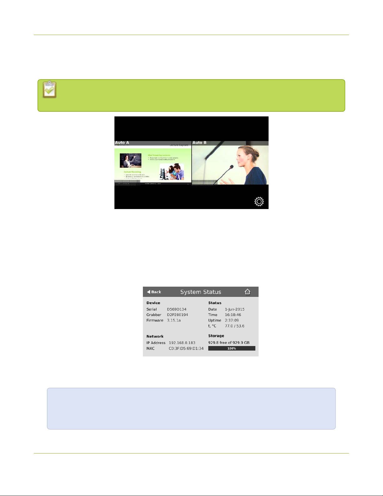
View system information
Useful when first setting up Pearl, for finding the system serial number or to check the installed firmware
version, the touch screen shows you basic information about your Pearl. If desired, you can choose to disable
this screen. See Configure the touch screen.
Label Description
Device Information
l Serial number
l video grabber number
38
Page 52

Pearl User Guide View system information
Label Description
l Firmware version
Network Information
l IP Address
l MACAddress
Device Status
l System date
l System time
l Uptime
l Temperature in degrees Celsius
Storage Information (when available)
l Disk space available
l Pictogram of available disk space
To show system information on the touch screen:
1. If the system settings button (gear)is not on the screen, tap the screen once to turn on the control
buttons.
2. If the system settings button is still not visible, it is disabled in the system's Touch screen configuration.
See Configure the touch screen to enable system information.
3. Touch the system settings button (gear) on the screen.
4. Touch System Status to see the System Status page.
39
Page 53

Pearl User Guide Channel monitoring
To close the system information screen:
1. Touch Back to return to the System Settings screen, or the Home icon to return to the channel view.
Channel monitoring
Use Pearl's front-panel screen to have complete confidence about what you're capturing. View audio levels
and a preview of the captured video for each channel. Change between individual channels or view a grid of all
channels using on-screen navigation buttons. You can also directly monitor audio quality using the 3.5 mm
audio jack located at the front of the device. Read more Pearl's audio jack.
You may also be interested in learning about video switching from the touch screen, see Live video mixing /
switching.
Individual channel monitoring
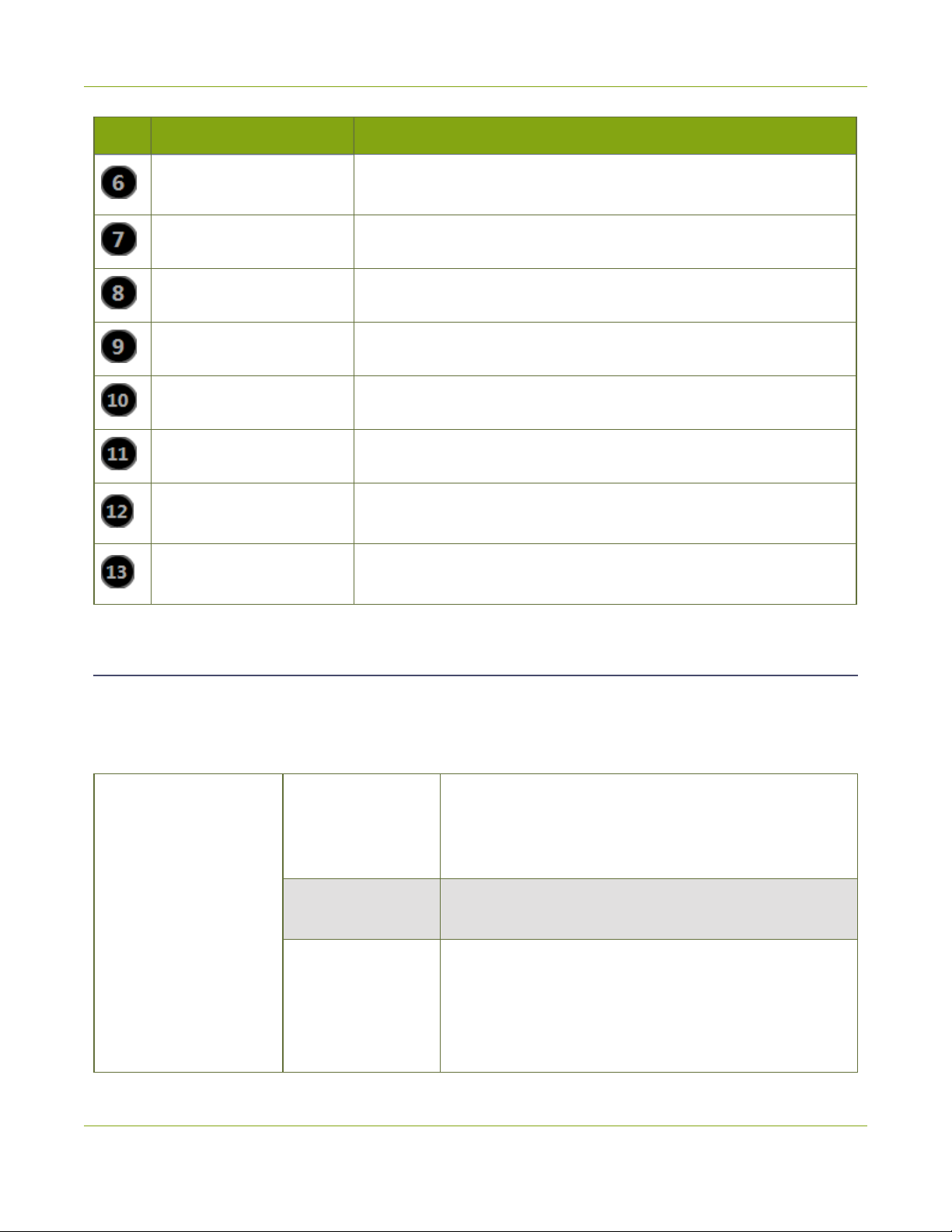
Table 8 Parts of the touch screen in individual channel view
Item Description
1 Channel name
2
Recording status (bright red means
recording is started)
40
Page 54

Pearl User Guide Channel monitoring
Item Description
3
4 Switch to the previous channel
5 Switch to the next channel
6 Audio VU meter
7 Grid view icon
8 System settings icon
To switch between available channels:
1. If necessary, tap the screen once to turn it on.
2. If necessary, tap the screen once to display controls on the channel view.
3. Touch the left or right controls on at the side of the channel display; the screen displays the next
channel.
To change from grid view to an individual channel view:
1. If necessary, tap the screen once to turn it on.
Recording timer (time since recording
was started)
2. Touch any channel in the grid view; the screen displays the selected channel.
Grid-view channel monitoring
Depending on the number of configured channels, the grid view will show 2, 3, 4, 5 or 6 channels at once.
Table 9 Parts of the touch screen in grid view
Location Description
Top left of channel Channel Name
41
Page 55

Pearl User Guide Pearl's audio jack
Location Description
Recording indicator, appears only if this
Top right of channel
channel is recording. (Recording control
only accessible from individual channel
view.)
Bottom left of
channel
lower right corner of
screen
To change from individual channel view to grid view:
1. If necessary, tap the screen once to turn it on.
2. If necessary, tap the screen once to display controls on the channel view.
3. Touch the grid view button; the screen displays the grid view
Audio level indicator.See Audio
VUMeter for description of levels.
Gear icon. Used to access settings.
Pearl's audio jack
Pearl's front panel includes a 3.5 mm audio jack for audio monitoring.
Audio monitoring
To use the audio monitor, plug speakers or a microphone into the 3.5 mm audio jack.
Use the touch screen to select a channel, that channel's audio is played through the speakers or headphone.
Audio is also played when switching layouts - and is always the audio for the currently live layout.
Mute audio monitoring
You can mute and unmute audio monitoring by touching the headphones icon on the touch screen.
42
Page 56

Pearl User Guide Control recording
Audio VUMeter
Regardless of whether or not speakers or headphones are plugged in, the touch screen also shows the audio
levels on a VU meter.The VU meter shows the RMS level in dBFS(decibels relative to full scale) and uses
colored bars to represent the current level.
Table 10 Touch screen audio VUmeter levels
Color Decibel range
Green -60 dB to -10 dB
Yellow -10 dB to -4 dB
Red -4 dB to 0 dB
Control recording
Pearl's touch screen gives you freedom to start and stop recording without needing to log in to the web
interface.
Simply scroll to the channel you wish to control and press the start or stop recording button.
43
Page 57

Pearl User Guide Control recording
To start recording:
1. If necessary, tap the screen once to turn it on.
2. If the grid view is showing, tap the channel for which you wish to control recording; the screen displays
the channel.
3. If necessary, tap the screen once to display controls on the channel view.
4. Touch the red record button (see above) at the top right of the screen; recording starts and a timer is
displayed to show the length of the recording.
To stop recording:
1. If necessary, tap the screen once to turn it on.
2. If the grid view is showing, tap the channel for which you wish to control recording; the screen displays
the channel.
3. If necessary, tap the screen once to display controls on the channel view.
4. Touch the red record button (see above) at the top right of the screen; recording stops and the timer
disappears.
44
Page 58

Pearl User Guide Configure the touch screen
Configure the touch screen
By default, Pearl's touch screen is enabled and all its features are available. Depending on your circumstances,
you may wish to disable the screen, or disable just some of its features.
This section covers the following touch screen configuration items:
l Disable (or enable)the touch screen
l Hide (or show) channel previews on the touch screen
l Disable (or enable) system status on the touch screen
l Block (or allow) configuration functions from the touch screen
l Block (or allow) recording control from the touch screen
l Set touch screen timeout
Disable (or enable)the touch screen
You can prevent Pearl from displaying anything on the touch screen, or you can re-instate this feature by
toggling the Enable display configuration option.
The display is always touch-sensitive. This control indicates whether or not the display is on
or off.
To disable (or enable) the touch screen display:
1. Connect to the admin interface using your preferred connection mechanism. See Connect to the admin
interface.
2. Login as admin.
3. Select the Touch Screen link in the Configuration menu; the touch screen configuration page opens.
45
Page 59

Pearl User Guide Configure the touch screen
4. Uncheck Enable display to disable the display (or check the box to enable the display).
5. Click Apply.
Hide (or show) channel previews on the touch screen
By default, Pearl shows previews of each configured channel. If this isn't suitable for your needs, you may
disable channel preview. When channel previews are disabled, the touch screen shows the following image:
While preview is disabled, if system status or settings and configuration preset changes
are permitted, you can touch the screen anywhere to open the settings page.
To hide (or show) the channel previews on the touch screen:
1. Connect to the admin interface using your preferred connection mechanism. See Connect to the admin
interface.
46
Page 60
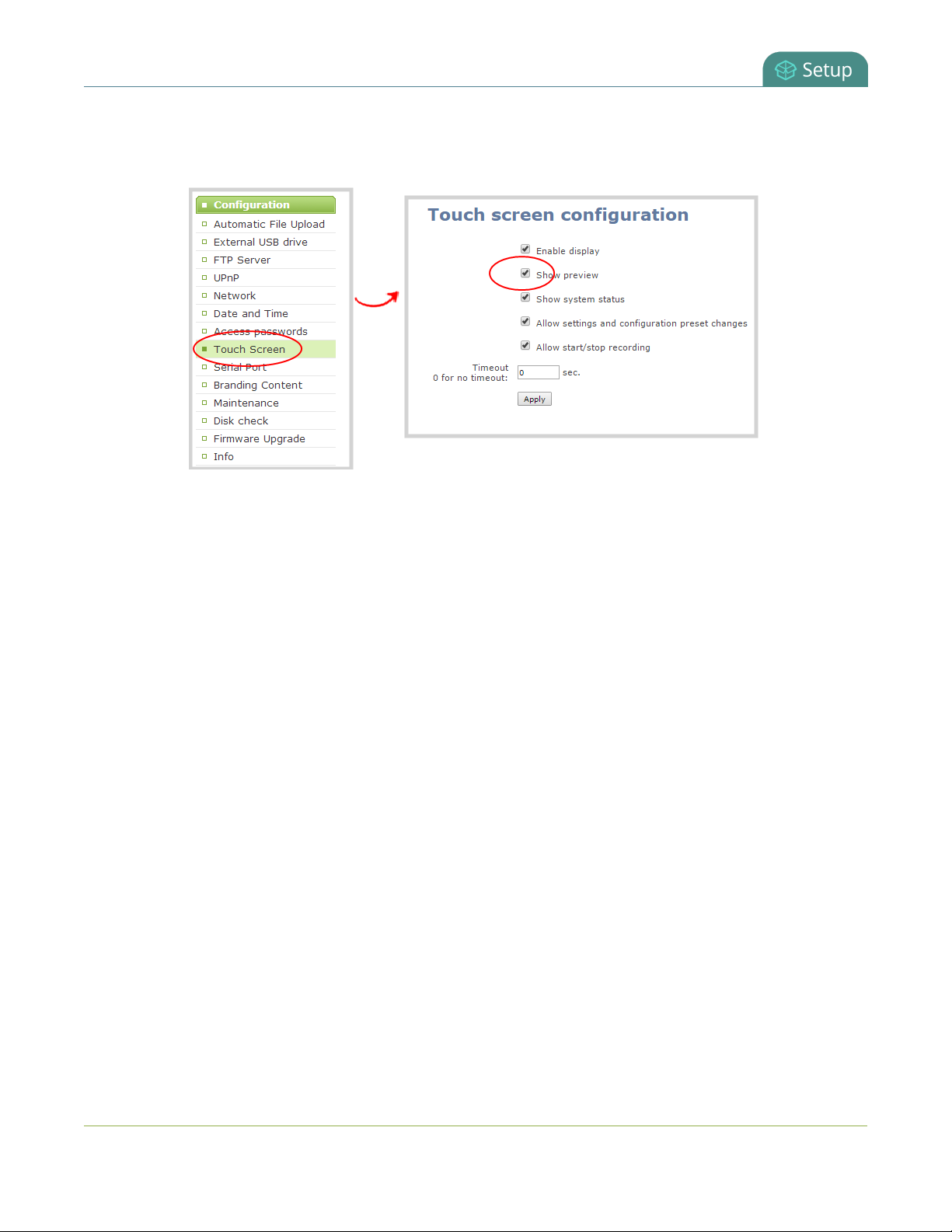
Pearl User Guide Configure the touch screen
2. Login as admin.
3. Select the Touch Screen link in the Configuration menu; the touch screen configuration page opens.
4. Uncheck Show preview to disable channel previews (or check the box to enable previews).
5. Click Apply.
Disable (or enable) system status on the touch screen
Once you've configured, Pearl its possible you may no longer wish to show the system status screen on the
touch screen. .
To hide (or show) system information on the touch screen:
1. Connect to the admin interface using your preferred connection mechanism. See Connect to the admin
interface.
2. Login as admin.
3. Select the Touch Screen link in the Configuration menu; the touch screen configuration page opens.
47
Page 61

Pearl User Guide Configure the touch screen
4. Uncheck Show system status to prevent the system status screen from being accessible on the
touch screen (or check the box to enable system information).
5. Click Apply.
Block (or allow) configuration functions from the touch screen
By default, Pearl permits applying configuration presets and configuring network settings via the touch
screen. You can disable this ability.
If configuration is blocked and system status is permitted, touch screen users see an i icon instead
of the configuration gears icon in the lower right corner of the touch screen.
To block (or allow) the channel previews on the touch screen:
1. Connect to the admin interface using your preferred connection mechanism. See Connect to the admin
interface.
2. Login as admin.
3. Select the Touch Screen link in the Configuration menu; the touch screen configuration page opens.
48
Page 62

Pearl User Guide Configure the touch screen
4. Uncheck Allow settings and configuration preset changes to disable configuration from the
touch screen (or check the box to enable configuration).
5. Click Apply.
Block (or allow) recording control from the touch screen
By default, Pearl permits recording control and live switching control for channels. You can disable this control
to prevent unwanted interruptions in recordings or to stop users from switching the layout used.
Channel preview must be on for recording and live switching control to work.
To block (or allow) the recording and live mixing / switching control via the touch screen:
1. Connect to the admin interface using your preferred connection mechanism. See Connect to the admin
interface.
2. Login as admin.
3. Select the Touch Screen link in the Configuration menu; the touch screen configuration page opens.
49
Page 63

Pearl User Guide Configure the touch screen
4. Uncheck Allow start/stop recording to disable recording control from the touch screen (or check the
box to enable recording control).
5. Click Apply.
6. Enter a value in the Timeout field. The values is in seconds. Use 0 to keep the screen on whenever the
system is on.
7. Click Apply.
Set touch screen timeout
Initially, the touch screen is always on for easy monitoring. However, if you'd like, you can modify its
configuration to cause it to shut off after a given amount of time. To re-enable it after timeout, simply touch
anywhere on the screen.
To set a timeout for the touch screen:
50
Page 64

Pearl User Guide Configure the touch screen
1. Connect to the admin interface using your preferred connection mechanism. See Connect to the admin
interface.
2. Login as admin.
3. Select the Touch Screen link in the Configuration menu; the touch screen configuration page opens.
4. Enter a value in the Timeout field. The values is in seconds. Use 0 to keep the screen on whenever the
system is on.
5. Click Apply.
51
Page 65

Pearl User Guide View system information
View system information
The system information page provides a great deal of useful information about your Pearl. Use the Info link
from the Configuration menu to view your current firmware level, system hardware version(if available) and
currently configured channels.
To view system information:
1. Connect to the admin interface using your preferred connection mechanism. See Connect to the admin
interface.
2. Login as admin.
3. From the web interface, scroll to the Configuration menu option.
4. Click Info; the system information page opens.
3. Use the information displayed to get an overview of your system, troubleshoot problems or view
streams for configured channels.
52
Page 66

Pearl User Guide Configure network settings
Configure network settings
By default Pearl uses DHCP to obtain an IP Address via an Ethernet-based network. If you want to change the
network settings, or if you’re having network-related issues, this section covers the network-related topics.
l Verify IP Address and MAC address via the touch screen
l Verify IP Address and MAC address via the web interface
l Configure a static IP address
l Configure DHCP
l Tether to a mobile network
l Perform network diagnostics
Verify IP Address and MAC address via the touch screen
Pearl's touch screen interface, if enabled, can quickly and easily show you the system's IPAddress and
MACaddress.
To show system information on the touch screen:
1. If the system settings button (gears) does not appear on the screen, tap the screen once to turn on the
control buttons (from the "no channels" or"preview disabled" screen, this will go directly to the system
settings screen).
2. If the system settings button (gears) is still not visible and an i icon is visible instead, configuration by
touch screen is disabled in the system's settings. See Configure the touch screen to enable.
3. Touch the system settings button (gears) on the screen; the system settings screen appears.
4. Touch System Status to see the system information page.
53
Page 67

Pearl User Guide
To close the system information screen:
1. Touch Back to return to the Systems Settings screen or the Home icon to return to the channel view.
Verify IP Address and MAC address via the web inter-
face
Verify IP Address and MAC address via the web interface
The web interface shows you the system’s MAC address and current IP Address via the Network configuration
page.
To view settings on network configuration page:
1. Connect to the admin interface using your preferred connection mechanism. See Connect to the admin
interface.
2. Login as admin.
3. Select the Network link in the Configuration menu; the network configuration page opens.
4. Note the MAC address and Current IP address listed at the top of the page.
Table 11 Network InformationFields
Label Description/Options
A media access control address (MAC address) is a unique identifier for the net-
MACAddress
work interface. The value is read-only and cannot be changed. You may need to
share this value with your system administrator.
Current IPAddress
Reflects the current internet protocol address (IP address) of the system. This
54
Page 68

Pearl User Guide Configure DHCP
Label Description/Options
value is either obtained from the DHCP server (if using DHCP) or is the configured
static IP address. Pearl supports IPv4 addresses. It does not support IPv6
addresses.
Configure DHCP
Occasionally, such as when moving your system to a new network, your Pearl must switch from static IP
address allocation to dynamic allocation via DHCP. You can accomplish this three ways:
l Restore factory settings, clearing all your custom settings. See Perform factory reset.
l Load a configuration file that uses DHCP networking. See Load a saved device configuration.
l Apply a configuration preset that usesDHCP networking. See Configuration presets.
l Change the network settings. See the procedure below.
For quick and easy setup of Pearl, you can configure network settings via the web interface or via touch
screen.
Using the touch screen, you can choose to apply a configuration presetsthat uses DHCP (see Configuration
presets
To configure network settings via the touch screen:
1. If the system settings button (gears) does not appear on the screen, tap the screen once to turn on the
control buttons (from the "no channels" or"preview disabled" screen, this will go directly to the system
settings screen).
2. If the system settings button (gears) is still not visible and an i icon is visible instead, configuration by
touch screen is disabled in the system's settings. See Configure the touch screen to enable.
3. Touch the system settings button (gears) on the screen; the system settings screen appears.
4. Touch Network ; the Network settings page appaers. The currently enabled type of network setting
(DHCP or static) is highlighted green.
55
Page 69

Pearl User Guide Configure DHCP
5. If not already using DHCP, touch DHCP to enable DHCP.
6. If DHCP was not the active network type, a confirmation message is displayed.
7. Touch OK; DHCPis enabled.
To configure use of DHCP for networking:
1. Connect to the admin interface using your preferred connection mechanism. See Connect to the admin
interface.
2. Login as admin.
3. Select the Network link in the Configuration menu; the network configuration page opens.
4. Select the radio button use DHCP, if not already selected.
5. Change the MTU Size value only if needed. See the table below for information on maximum
transmission unit (MTU) values.
6. Click Apply to save the changes; the changes are saved and a message appears asking you to reboot.
7. Select the Maintenance link under the Configuration menu; the maintenance page appears.
8. Click the Reboot Now button near the bottom of the page.
9. Wait for the system to reboot.
10. Connect to the admin interface using your preferred connection mechanism. SeeConnect to the admin
interface.
11. Log as admin and reload the Networking page to verify all changes were applied.
The following table describes the fields applicable when configuring DHCP on Pearl.
56
Page 70

Pearl User Guide Configure a static IP address
Table 12 DHCP Fields
Label Description/Options
Use DHCP Select this radio button to dynamically obtain an IP address at boot up.
Use static
address
MTU Size
Use static address Select this radio button to use the configured static IP address.
The maximum transmission unit (MTU) specifies the maximum packet size for transfer on
the network. The default value is 1500, which is the largest value allowed by Ethernet at
the network layer. It’s best if all nodes in your network use the same value, so only change
this value if you know other nodes use a different value.
Configure a static IP address
Your network administrator may require you to use a static IP address for your Pearl.
For quick and easy setup of Pearl, you can configure network settings via the web interface or via touch
screen.
Using the touch screen, you can choose to apply a configuration presetsthat contains a static network IP (see
Configuration presets
To configure network settings via the touch screen:
1. If the system settings button (gears) does not appear on the screen, tap the screen once to turn on the
control buttons (from the "no channels" or"preview disabled" screen, this will go directly to the system
settings screen).
2. If the system settings button (gears) is still not visible and an i icon is visible instead, configuration by
touch screen is disabled in the system's settings. See Configure the touch screen to enable.
3. Touch the system settings button (gears) on the screen; the system settings screen appears.
4. Touch Network ; the network settings page appears. The currently enabled type of network setting
(DHCP or static) is highlighted green.
57
Page 71

Pearl User Guide Configure a static IP address
5. Touch Static IPAddress to configure a static IP address; the static IP configuration page appears.
6. Touch an IP Address section (e.g. 192) and type a new value using the keypad.
7. Repeat for all fields in the IP Address and Network Mask.
Only IPv4 addresses are supported.
8. Enter the Default Gateway address. If you do not have a default gateway for your network, enter the
same static IP address as in the previous step.
The default gateway cannot be left blank. If no default gateway is specified, unexpected
behavior occurs.
9. Enter the DNS Server address. If you do not have a DNS server, enter the new static IP address of the
system.
10. Touch Apply to apply the changes.
To configure a static IP address via the web interface:
1. Connect to the admin interface using your preferred connection mechanism. See Connect to the admin
interface.
2. Login as admin.
3. Select the Network link in the Configuration menu; the network configuration page opens.
58
Page 72

Pearl User Guide Configure a static IP address
4. Select the radio button use static address, if not already selected.
5. Enter the desired IP Address and Network Mask.
Only IPv4 addresses are supported.
6. Enter the Default Gateway address. If you do not have a default gateway for your network, enter the
same static IP address as in the previous step.
The default gateway cannot be left blank. If no default gateway is specified, unexpected
behavior occurs.
7. Enter the DNS Server address. If you do not have a DNS server, enter the new static IP address of the
system.
8. Change the MTU Size value only if needed. See the table below for information on maximum
transmission unit (MTU) values.
9. Click Apply to save the changes; the changes are saved and a message appears asking you to reboot.
10. Select the Maintenance link under the Configuration menu; the maintenance page appears.
11. Click the Reboot Now button near the bottom of the page.
59
Page 73

Pearl User Guide Tether to a mobile network
12. Wait for the system to reboot.
13. Open the Web interface using the new IP address.
14. Log as admin and reload the Networking page to verify all changes were applied.
The following table describes applicable fields when setting a static IP address.
Table 13 Static IPAddress Fields
Label Description/Options
Use DHCP Select this radio button to dynamically obtain an IP address at boot up.
Use static address Select this radio button to use the configured static IP address.
The internet protocol address (IP Address) to assign. This value is may be obtained
IP Address
Network Mask
from your system administrator. Pearl supports IPv4 addresses. It does not support
IPv6 addresses.
Also called the subnet mask, this value denotes a range of IP addresses. This value
may be obtained from your system administrator, determined from another computer on the same subnet, or calculated using an online subnet calculator.
The network node that serves as an access point to the rest of the network. This value
Default Gateway
DNS Server
MTU Size
cannot be blank unless you are using DCHP. Specify the system’s IP address if you
don’t have a default gateway on your network.
The domain name system server (DNS server) translates human-readable hostnames
into corresponding IP addresses. Specify the system’s IP address if you don’t have a
DNSserver on your network. This value cannot be blank unless you are using DHCP.
The maximum transmission unit (MTU) specifies the maximum packet size for transfer on the network. The default value is 1500, which is the largest value allowed by Ethernet at the network layer. It’s best if all nodes in your network use the same value, so
only change this value if you know other nodes use a different value.
Tether to a mobile network
Pearl supports tethering to a mobile device via USB. Tethered networking can work side-by-side with Ethernet
routing and either networking system can be a back-up for the other.
When the system falls over to the backup network type (i.e. from Ethernet to mobile, or vice
versa) all streaming sessions with clients or servers directly connected to the system are closed
60
Page 74

Pearl User Guide Tether to a mobile network
and the clients will need to reconnect. You may need to provide a new stream URL(containing the
new IPaddress) to your viewers. See the channel information page to get the new stream URL.
By contrast, actively published streams are closed and reconnected via the secondary network
(mobile or Ethernet) automatically, permitted the required publishing server is accessible from the
new network.
To configure tethering to a mobile network:
1. Configure the mobile device to allow tethering via USB.
2. Connect the mobile device to Pearl with a USB cable.
3. Connect to the admin interface using your preferred connection mechanism. SeeConnect to the admin
interface.
4. Login as admin.
5. Select the Network link in the Configuration menu; the network configuration page opens.
6. Click the drop-down box next to Use phone/tablet connection in the USB phone/tablet section; the
following choices appear:
Table 14 Mobile Tethering Options
Label Description/Options
Disabled Specifies that no USB tethering is permitted.
No tethering
Prefer ethernet
Prefer tethering
Specifies that USB tethering is available for connecting a mobile device as a configuration utility (i.e. using the web browser), but no mobile data is used.
When chosen, the system tries to use the Ethernet network first. It switches to use
the mobile network (tethering) when the Ethernet network is no longer available.
To prevent viewer interruptions, mobile data will continue to be used until the
mobile network is down or publishing is restarted.
When chosen, the system tries to use the mobile network (tethering) first. It
switches to use Ethernet (hard-wired) when the mobile network is no longer
available. To prevent viewer interruptions, Ethernet data will continue to be used
until the Ethernet network is down or publishing is restarted.
Select this setting if you only have a mobile network.
7. Select your choice based on the table above.
8. Click Apply.
61
Page 75

Pearl User Guide Perform network diagnostics
Perform network diagnostics
If your Pearl has network trouble, you can perform basic network troubleshooting tasks from the Network
configuration page. In addition to providing the system’s IP address and MAC address to your network
administrator (See Perform network diagnostics), you can also ping an IP address or use traceroute to
determine the path taken to an address.
Note: Not all networks support ping and traceroute.
To ping or traceroute an IP address:
1. Connect to the admin interface using your preferred connection mechanism. See Connect to the admin
interface.
2. Login as admin.
3. Select the Network link in the Configuration menu; the network configuration page opens.
4. Click ping or traceroute; an animation appears to the left of the address to indicate processing is
underway.
5. Upon completion of the command, read the results from the console-like display is shown below the
Network Diagnostics setting.
62
Page 76

Pearl User Guide Perform network diagnostics
63
Page 77

Pearl User Guide Configuration presets
Configuration presets
In situations where you have changing configuration requirements for your Pearl, you can use
configurationpresets to quickly and easily apply sets of pre-configured settings.
For an overview of configuration presets, see:
l Configuration presets overview
This section also covers the following related topics:
l Configuration groups
l Create a configuration preset
l Apply a configuration preset from the web interface
l Apply a configuration preset using the touch screen
l Apply theFactory default configuration preset
l Update a configuration preset
l Delete a configuration preset
There are also some very important configuration preset considerations to review:
l Configurationpreset considerations
Configuration presets overview
Configuration presets make it easy to use your Pearl in a variety of situations without needing to reconfigure
it. Configuration presets divide the system's settings into the following six configuration groups. (For a
complete list of what is included in each group see Configuration presets overview.)
System Sources Automatic file uploads
Network Channels Touch screen
Using the Configuration presets section of the Maintenance page, you can create configuration presets
using any number and combination of the configuration groups. Mix and match the settings groups saved
together to create sets of configuration settings needed for each situation. You also always have a special
64
Page 78

Pearl User Guide Configuration presets overview
Factory default configuration preset (which cannot be erased) to help you return to factory configuration
without destructively erasing files saved to the system hard drive. (See Configuration presets overview
It's important to note that configuration presets are applied over existing settings. They affect only the
settings groups included in the preset, all other settings are unaffected. Read the Configuration presets
overview section carefully to understand caveats around using configuration presets.
Example of configuration presets in action
A recording and streaming company brings Pearl to a conference. Each conference session needs to be
streamed and recorded with a picture in picture layout that includes identifying information about the
presenter in the metadata and the background image for the stream. Automatic file upload is needed to make
sure the files are uploaded right after each session is complete.
The company could bring Pearl in a factory configured state and get it ready between each session, but this
requires a trained operator and doesn't allow much time to get multiple operations completed.
Instead, the company could connect the system to their own corporate network before the show, upload the
required backgrounds, and create channel configuration presets for each conference track. They can also
create network and automatic file upload (AFU) presets for each of the home and remote locations. Once at
the conference, the only changes necessary are to apply the network and AFU preset upon arrival, and the
channel configuration presets between sessions. Note that for added simplicity, you can load presets via the
touch screen!
Channel configuration presets include links to background files used, but do not include the files
themselves see Branding content. Be careful when deleting background images and logo files.
Internal network and AFU preset
The company uses this preset when configuring and testing from their corporate network. It uses a static IP
address on their corporate network and AFU that uses ftp to upload to a local ftp server.
65
Page 79

Pearl User Guide Configuration presets overview
Conference network and AFUpreset
The company applies this preset to Pearl when they arrive at the conference. It changes only the network and
AFU settings (using a conference-specific IP address and secure file transfer to an ftp server).
When applying this configuration preset, all other information including passwords, date/time, channels and
source configurations, remains the same.
Conference session 1 preset
The company applies this preset from the corporate office when testing and at the conference prior to
conference session 1 starting. All other preset groups remain unchanged, this preset only affects the channel
(s) and their configuration. This preset includes a channel with a link to the correct background filename (the
background file was uploaded during pre-show configuration at the corporate office) and has metadata
specifying the speaker's name.
Conference session 2 preset
The company applies this preset from the corporate office when testing and at the conference prior to
conference session 2 starting. After applying this preset the files recorded from session 1 remain present on
the system and continue to upload via sftp (if not yet complete), but the channels reflect the session 2
background file name and presenter name.
66
Page 80

Pearl User Guide Configuration groups
Configuration presets are a versatile tool to help you use Pearl in a variety of changing conditions. Try it
yourself and see!
Configuration groups
The following table describes what settings are saved with each configuration group.
Table 15 Configuration group definitions
Group Name Symbol Settings included in the configuration group
Date and time settings, serial port settings, remote support settings, custom
System
Network Network settings and tethering configuration.
Sources All audio and video source configuration settings.
Channels
AFU Automatic file upload type and parameters.
disk check schedule, access passwords, deny/allow lists and LDAPconfiguration
settings
All channel configuration data and current recording state, all layouts, all
recorder configuration data and current recording state, individual and global
UPnP settings.
Touch screen Permitted touch screen use settings.
67
Page 81

Pearl User Guide Create a configuration preset
Note that branding content, recorded files and SFTP/SCP private keys are not included in
any configuration preset.
Updloaded EDID configurations are applied immediately to the system and remain the norm for
the source until a new EDID is uploaded. Configuration presets do not affect EDIDs.
Create a configuration preset
You can create as many configuration presets as you need. The system keeps track of which configuration
groups are part of the preset and you provide a name that lets you know the significance of the preset.
Note that configuration presets that include network or system settings require a system
reboot when applied.
To create a configuration preset:
1. Connect to the admin interface using your preferred connection mechanism. See Connect to the admin
interface.
2. Login as admin.
3. Select the Maintenance link in the Configuration menu; the maintenance page opens.
4. Scroll to the Configuration presets section.
68
Page 82

Pearl User Guide Apply a configuration preset from the web interface
5. Type a description for your preset in the Name field.
6. Ensure only the desired configuration groups are selected from the Sections group.
7. Click Save; your configuration preset appears in the list.
Apply a configuration preset from the web interface
When you apply a configuration preset, the system settings for all included configuration groups are updated.
Other settings on the system are not affected. For example if you apply a preset that includes the
configuration groups channnels and automatic file upload, your network settings, passwords, time server,
source configurations, etc are not modified. Similarly if you apply a configuration preset that has only
network settings included, only the network settings change.
If you apply a preset that has the network or system configuration group, a reboot is required.
You can verify which configuration groups are included in a preset by looking at the list to the right of the
configuration preset name. The term 'all' means all groups are included. Otherwise groups are listed
individually.
69
Page 83

Pearl User Guide Apply a configuration preset from the web interface
You may apply multiple presets one after another. If you apply two (or more) configuration
presets that include a particular configuration group, the settings (for that group) from the last
applied preset are the active settings. In short, last in wins.
To apply a configuration preset from the web interface:
1. Connect to the admin interface using your preferred connection mechanism. See Connect to the admin
interface.
2. Login as admin.
3. Select the Maintenance link in the Configuration menu; the maintenance page opens.
4. Scroll to the Configuration presets section.
5. Click Apply next to the configuration preset you wish to apply.
6. The system asks for confirmation before proceeding.
If the configuration preset includes the network or system configuration groups, a
reboot is necessary.
70
Page 84

Pearl User Guide Apply a configuration preset using the touch screen
7. ClickOK to apply the configuration preset; the configuration preset is applied.
8. The system reboots if needed.
Apply a configuration preset using the touch screen
You can use Pearl's touch screen to apply configuration presets.
For configuration presets that only contain the network configuration group you can use either of the two
methods described below. For all other configuration presets, use the first method.
To apply a configuration preset via the touch screen:
1. If necessary, tap the screen once to turn it on or to turn on the screen overlay.
2. If the system settings button (gear) is still not visible and an i icon is visible instead, configuration by
touch screen is disabled in the system's settings. See Configure the touch screen to enable.
3. Touch the gear icon at the bottom right of the screen; the settings page appears.
4. Touch ConfigurationPresets; an alphabetically sorted list of saved presets is presented (Factory
default is always listed first). Each preset shows the included preset configuration groups via a list of
icons to the right of the preset name.
71
Page 85

Pearl User Guide Apply a configuration preset using the touch screen
5. If necessary touch the arrows at the bottom of the page to navigate to the desired preset.
6. Touch the name of the preset you wish to apply.
7. A confirmation message is displayed.
If the configuration preset includes the network or system configuration groups, a
reboot is necessary.
8. Click OK to apply the preset; the configuration preset is applied.
9. The system reboots, if required.
To apply a configuration preset that contains only the network configuration group you may use this process:
1. If necessary, tap the screen once to turn it on or to turn on the screen overlay.
2. Touch the gear icon at the bottom right of the screen; the settings page appears.
72
Page 86

Pearl User Guide Apply a configuration preset using the touch screen
3. Touch the Network line; the network configuration page opens.
4. Touch NetworkPresets; a list of saved configuration settings with onlyNetwork settings opens.
5. Touch the name of the preset you wish to apply; a confirmation message is displayed.
73
Page 87

Pearl User Guide Apply theFactory default configuration preset
6. ClickOK to apply the network configuration preset and reboot the system.
Apply theFactory default configuration preset
Your Pearl comes with a special factory default configuation preset.This configuration preset cannot be
erased and is always presented at the top of the configuration presets list. It contains all six possible
configuration settings groups.
Using the Factory default configuration setting is similar to using the Factory reset method(see Perform
factory reset with a few important differences.
In short, the Factory default configuration preset is less destructive than Factory reset. This table
describes the exact differences.
Table 16 Factory default configuration preset vs Factory reset
Deletes all created channels
Deletes all recorded files in channels
Deletes all created recorders
Deletes all recorded files in recorders
Resets network configuration
Resets touch screen configuration
Resets user passwords
Factory default
configuration preset
ü ü
ü
ü ü
ü
ü ü
ü ü
ü ü
Factory reset function
Deletes all created configuration presets
ü
74
Page 88

Pearl User Guide Update a configuration preset
Deletes all branding files
Resets all Source settings
Deletes all Automatic file upload settings
To apply the factory default configuration preset, follow the instructions in Apply theFactory default
configuration preset or Apply theFactory default configuration preset and select the Factory default preset.
A reboot is required.
Factory default
configuration preset
ü
ü ü
ü ü
Factory reset function
Update a configuration preset
If you need to update a configuration preset to include different configuration groups, or simply new settings
for the same groups, you can do so easily via the web interface.
To update a configuration preset:
1. Connect to the admin interface using your preferred connection mechanism. See Connect to the admin
interface.
2. Login as admin.
3. Select the Maintenance link in the Configuration menu; the maintenance page opens.
4. Scroll to the Configuration presets section.
75
Page 89

Pearl User Guide Delete a configuration preset
5. Find the preset you wish to change from the presets list.
6. Copy the name of the preset into the Name field.
7. Selected the desired configuration group(s) from the Sections group.
8. Click Save; a confirmation dialog asks you to confirm you want to overwrite the configuration preset.
9. Click OK; your configuration preset is updated in the list.
Delete a configuration preset
You may want to trim the list of configuration presets to only those that are needed for your ongoing needs.
You can delete all configuration presets at once by doing a factory reset, or you can delete individual
configuration presets from theMaintenance page.
To delete a configuration preset:
1. Connect to the admin interface using your preferred connection mechanism. See Connect to the admin
interface.
2. Login as admin.
76
Page 90
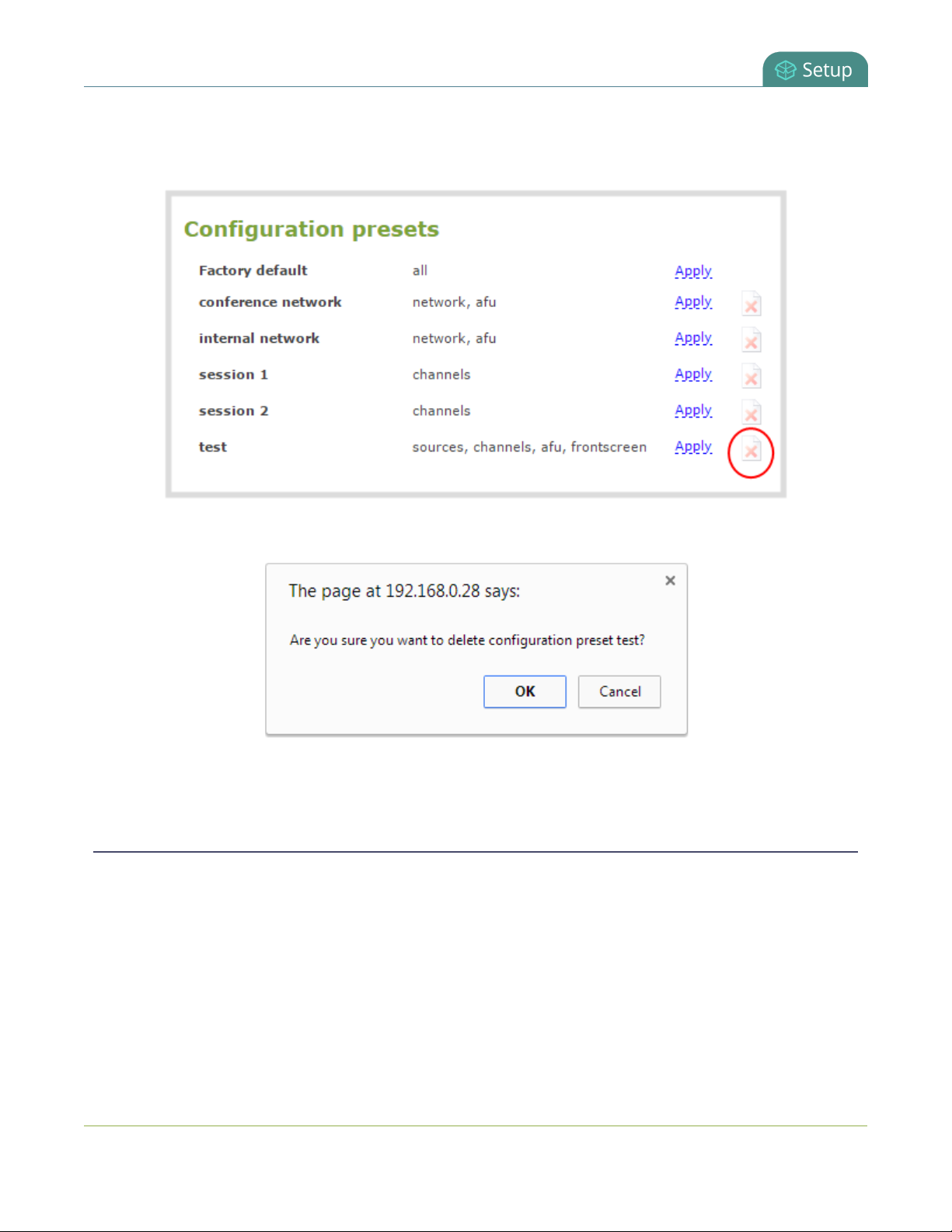
Pearl User Guide Configurationpreset considerations
3. Select the Maintenance link in the Configuration menu; the maintenance page opens.
4. Scroll to the Configuration presets section.
5. Click delete (x) next to Apply for the configuration preset; a confirmation message appears.
6. Click OKto confirm you want to delete the preset; the preset is deleted.
Configurationpreset considerations
Configuration presets are groups of settings applied to the system, leaving other settings intact. The following
considerations will help you get the most from your configuration presets.
Channel and recorder index number behavior
Each channel and recorder has an index number. The first channel created on a system is channel 1,
subsequently channel 2, 3, 4, etc. Recorders are also created starting at index 1 with numbers incrementing as
new recorders are created. The channel (or recorder) index number is found to the left of the channel or
recorder name in the web interface:
77
Page 91
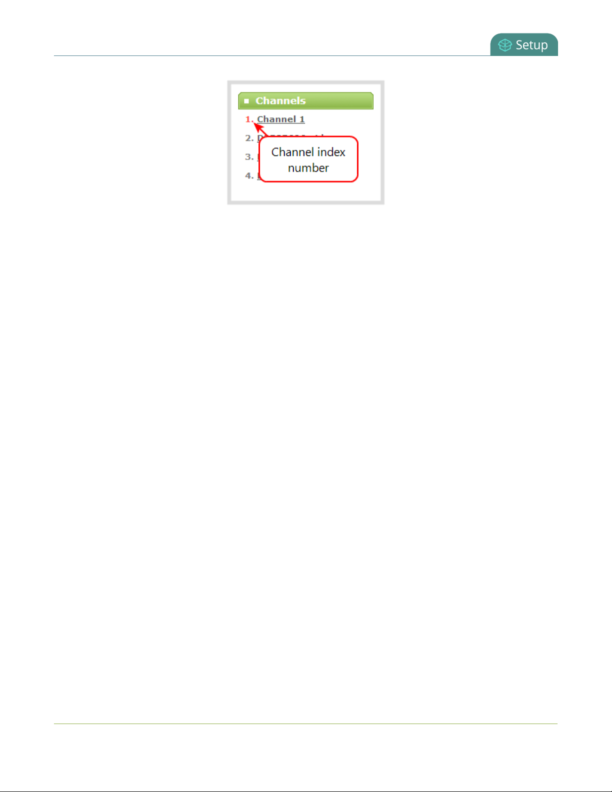
Pearl User Guide Configurationpreset considerations
Configuration presets that contain the channels configuration group specify the channels in the preset by
their index number. This means if you have channels 1, 2, 3 and 4 when you save your preset, applying that
preset will overwrite the configuration of your current channels with indexes 1, 2, 3 and 4. If prior to applying
that preset you also had channels with indexes 5 and 6, the configuration settings for those two channels are
when the preset is applied(because the preset only has 4 channels).
There are three areas where channel (and recorder) index numbers affect what happens when applying
configuration presets. Read Recording StateRecorded files (in channels and recorders) and Deleting channels
for more information.
Recording State
The Configurationpreset considerations section of this chapter shows that each channel and recorder's
recording state is included in the channels configuration group. This means that if a channel (or recorder) is
recording at the time you create a configuration preset, it will immediately start recording when you apply that
preset. Similarly, if a configuration preset is saved when channels or recorders are not recording, those
channels and recorders will not be recording when the preset is applied (this means a channel or recorder may
stop recording as a result of applying the preset).
For example, when applying a preset with channel 3 set to record:
l If channel 3 exists prior to applying the preset and is already recording, the file will continue recording
uninterrrupted unless the recording file type is differentin the preset (in which case a new file is
started).
l If channel 3 exists prior to applying the preset and is not already recording, it immediately begins
recording.
l If no channel with index 3 exists prior to applying the preset, the channel is created and it immediately
begins recording.
78
Page 92

Pearl User Guide Configurationpreset considerations
Recorded files (in channels and recorders)
Channels and recorders keep a list of files recorded in theirRecordings section of the web interface. These
files remain on the system even if the channel or recorder configuration is changed or removed as a result of
applying a configuration preset.
For example, prior to applying your configuration preset, you have channels with indexes 1, 2 and 3; each of
these has five recording files. When you apply a configuration preset that has channels with index 1 and 2
only, you'll notice those channels each still have the same 5 recording files. Channel with index 3 is no longer
present, but the files are not lost!
Overwritten channel files are still available. To access and download/delete these recorded files, enter the
following into the address bar: http://<deviceIP>/admin/channelN/archive or
http://<deviceIP>/admin/recorderN/archive, where N is the index of the removed channel/recorder.
For example, if a Channel with index 3 is no longer present, its corresponding files can be accessed by
entering the following into the address bar:
l http://192.168.0.183/admin/channel3/archive
If you now create a new channel with index 3 (or load a preset that contains a channel with index 3), you'll find
it starts with five recorded files in the Recordings section. These are the same recorded files that existed at
the start of this example.
Furthermore, if you delete any of the recordings, you are deleting the only instance of those files. Using our
previous example, if you delete one of the five recordings from channel index 1, you'll find that even after
applying different presets channel 1 will have only four recorded files.
Deleting channels
Recorded files are stored on the system based on their channel or recorder number. All files saved for channel
index 1 are in one folder, and all files for recorder index 2 are in another. When you delete a channel (or
recorder), you permanently delete all recordings for that channel (or recorder) even if those recordings were
made while a different preset is applied.
Note applying a configuration preset with a different set of channels or recorders is not the same
as deleting a channel.
When deleting a channel or recorder that has recorded files, the web interface warns you of other
configuration presets that use the same channel or recorder index numbers. When you see this prompt, we
recommend you take a moment to look through the Recordings list to make sure you're OK to proceed with
permanently deleting all the recorded files.
79
Page 93

Pearl User Guide Configurationpreset considerations
Branding content
The channels configuration group includes the filenames for logos and backgrounds used in the currently
configured channels. It does not include the image files. Therefore it is important to make sure that between
uses of different channel-related configuration presets you do not delete or replace files listed in the
Branding Content section of the web interface. There is currently no configuration group that includes the
Branding Content files.
EDIDs
EDIDs are uploaded and immediately applied to a specific source. This change remains in place until the user
uploads a new EDID or requests the factory EDID is applied by using the Restore default EDID button (see
Force the capture card to use a specific EDID
If you apply a preset that needs a special EDID, be sure to remember to upload that EDID after applying the
configuration preset.
Configuration presets are not user profiles
Configuration presets should not be confused with the concept of user profiles. Specifically, the following
issues arise from trying to use configuration presets as user profiles:
l recorded files are not removed between application of configuration presets (users could see each
other's files)
l configuration presets can be overwritten and deleted with no password (users could affect each other's
presets)
l branding and recorded files can be deleted, affecting more than just the currently applied configuration
presets (users could erase branding or recordings belonging to other users)
l applying a configuration presets does not clear the settings from groups not part of the preset (user
information is not private)
80
Page 94

Pearl User Guide Configurationpreset considerations
Touch screen considerations
The touch screen configuration group includes all the security settings for the touch screen. One such
setting is the ability to use the touch screen. It is therefore possible to apply a preset via the touch screen that
effectively locks out any further use of the touch screen. If this happens accidentally, use the web interface to
re-enable the touch screen (see Configure the touch screen).
81
Page 95

Pearl User Guide Configure date and time
Configure date and time
Pearl uses the current date and time in naming recorded files and when synchronizing and timestamping
inputs from multiple sources (i.e. when synchronizing an audio and a video source). The admin interface lets
you specify date and time settings to ensure they are correctly configured for your time zone and your
network.
This section covers the following date and time-related topics:
l Verify date and time via the touch screen
l Verify date and time settings
l Change the time zone
l Configure synchronized time (NTP, PTP v1, and RDATE)
l Configure a Local NTP Server
l Configure the date and time manually
Verify date and time via the touch screen
Pearl's touch screen interface, if enabled, can quickly and easily show you the system's date and time settings.
To show system information (including date and time) on the touch screen:
1. If the system information button (i) does not appear on the screen, tap the screen once to turn on the
control buttons.
2. If the system information button (i) is still not visible, it is disabled in the system's Touch screen
configuration. See Configure the touch screen to enable system information.
3. Touch the system information button (i) on the screen; the system information screen appears.
To close the system information screen:
1. Touch anywhere on the screen to return to the previous screen.
82
Page 96

Pearl User Guide Verify date and time settings
Verify date and time settings
The current date, time, time zone, and synchronized time protocol settings are shown when the Date and
Time configuration page is loaded in the Pearl web interface.
To view settings on the date and time configuration page:
1. Connect to the admin interface using your preferred connection mechanism. See Connect to the admin
interface.
2. Login as admin.
3. Select the Date and Time link in the Configuration menu; the date and time configuration page opens
and the following information is displayed:
The date and time configuration page also indicates whether the system is currently using synchronized or
manually set time, and whether or not a local network time protocol (ntp) server is running.
The following table describes the date and time configuration fields.
Table 17 Date and Time Options
Label Description/Options
Time Zone The currently selected time zone.
Enable time synchronization
Protocol The time synchronization protocol.
ServiceIPAddress The time synchronization server address.
Set time manually
Date
Whether or not a time synchronization protocol is being used for setting time. (If not
selected, time is set manually.)
Whether or not time is set manually. (If time is not being set manually, a time synchronization protocol is used.)
The current date. (This is the current date even if the radio button Set time manually is
not selected.)
83
Page 97

Pearl User Guide Configure synchronized time (NTP, PTP v1, and RDATE)
Label Description/Options
Time
The current time. (This is the current time even if the radio button Set time manually is
not selected.)
Configure synchronized time (NTP, PTP v1, and RDATE)
By default Pearl uses the network time protocol server (NTP server) protocol and a time server from National
Research Council Canada. You can continue to use this time server or configure a new server that is more
appropriate for your network and location. Your system administrator can provide the correct time
synchronization server settings.
To set the time synchronization method:
1. Connect to the admin interface using your preferred connection mechanism. See Connect to the admin
interface.
2. Login as admin.
3. Select the Date and Time link in the Configuration menu; the date and time configuration page
opens.
4. Click the Enable time synchronization radio button if it is not already selected.
5. Choose one of the following choices from the Protocols drop down:
Table 18 Synchronized Time Options
Label Description/Options
Network Time Protocol (NTP) is used for clock synchronization over the internet.
NTP
RDATE
PTP v1
6. Tailor the synchronization protocol with the required parameters as described below.
7. If NTP is selected:
a. Enter the IP address or server name for the NTP server in the Server IP Address field.
There are many publicly available NTP servers you can use, or your company may
have its own NTP server. For more information about NTP and to find
NTPservers, refer to http://support.ntp.org/bin/view/Servers/WebHome.
RDATE is a tool for querying the current time from the network. It is generally
considered obsolete and has been replaced by NTP. It's offered here for backwards compatibility with older timekeeping systems.
The Precision Time Protocol (PTP) is used for clock synchronization over the internet. It has clock accuracy in the sub-microsecond range, making it more granular
than NTP.
84
Page 98

Pearl User Guide Configure the date and time manually
NTP uses UDP packets and port 123. If the system is behind a firewall and accessing an
external NTP server, UDP packets must be permitted on port 123.
8. If RDATE is selected:
a. Enter the IP address or server name for the RDATE server in the Server IP Address field.
b. Select an update interval from the drop down box.
9. If PTP v1 is selected:
a. Select the multicast address of PTP v1 server from the PTPdomain drop-down.
PTP Domain Description
Default PTPat multicast address 224.0.1.129
Alternative 1 PTPat multicast address 224.0.1.130
Alternative 2 PTPat multicast address 224.0.1.131
Alternative 3 PTPat multicast address 224.0.1.132
PTP uses UDP packets and ports 319 and 320 . If the system is behind a firewall and
accessing an external PTP server, UDP packets must be permitted on ports 319 and 320.
10. Click Apply.
Configure the date and time manually
By default Pearl uses NTP for time synchronization. If your system does not have access to a time
synchronization server, or if you do not wish to use one, you can choose to manually set the date and time.
To manually set the date and time:
1. Connect to the admin interface using your preferred connection mechanism. See Connect to the admin
interface.
2. Login as admin.
3. Select the Date and Time link in the Configuration menu; the date and time configuration page
opens.
4. Type the desired date in the Date field. Use the format yyyy-mm-dd.
85
Page 99

Pearl User Guide Change the time zone
5. Type the desired time in the Time field. Use the format hh:mm:ss.
6. Click Apply.
Change the time zone
By default the system has the Canada/Eastern time zone set. Configuration of the time zone is necessary to
ensure synchronized time servers provide the correct time to the system.
To select another time zone:
1. Connect to the admin interface using your preferred connection mechanism. See Connect to the admin
interface.
2. Login as admin.
3. Select the Date and Time link in the Configuration menu; the date and time configuration page
opens.
4. Select the new time zone from the Time Zone drop down box.
5. Click Apply.
Configure a Local NTP Server
Pearl can run a local NTP server.
To configure a local NTP server:
1. Connect to the admin interface using your preferred connection mechanism. See Connect to the admin
interface.
2. Login as admin.
3. Select the Date and Time link in the Configuration menu; the date and time configuration page
opens.
4. Select the check box Enable local NTP server.
86
Page 100

PART 2:
Capturing is the process of taking the signals from your video and audio sources and encoding them in a
format that is ready for streaming and recording.
If you followed the quick start guide, you're already capturing, streaming and possibly recording your sources.
The section of the guide helps you fine tune and troubleshoot the capturing process.
When using Pearl, you can stick to all the default capture and encoding settings, or you tweak them to set the
up exactly as you like.
You can capture a single source at once, capture multiple sources in a custom channel or even switch between
sources or groups of sources(layouts) while streaming and recording.
Techniques for creating channels to capture, stream and record a single source; to create custom channels
with multiple sources and multiple layouts; and how to switch layouts while capturing are all described in this
section.
The chapters in this section are:
l Channels
l Live video mixing / switching
Capture
l Sources
l Troubleshooting
87
 Loading...