

Page 1

Epiphan Technical
Documentation
©2013
Epiphan Systems Inc.
All Rights Reserved
June 2013
DVI Broadcaster DL™
User Guide
www.epiphan.com
Page 2

Thank you for choosing Epiphan!
At Epiphan Systems Inc. (“Epiphan”), product function and quality are our top
priority. We make every effort to make sure that our products exceed our
customers’ expectations.
Product Feedback
We regularly contact our customers to ensure product performance and
reliability. We strive to continually enhance our products to accommodate your
needs. We welcome your feedback and suggestions for product improvements.
You can email your comments to info@epiphan.com.
Specifications
You can go to the Broadcasting page of the Epiphan website to get information
about the DVI Broadcaster DL.
Warranty
All Epiphan Systems products are provided with a 100% return to depot
warranty for one year from the date of purchase.
Technical Support
Epiphan is staffed by a professional support team. If, after checking the FAQs
for your product on the Epiphan website and re-installing the Epiphan driver
software (where applicable), you continue to have outstanding issues, email a
problem report to support@epiphan.com. To help us solve the problem
efficiently, include the following info:
Your DVI Broadcaster DL serial number.
The behavior of your DVI Broadcaster DL LED indicators.
Technical description of the signal source including resolution, refresh
rate, synchronization, type of hardware.
Complete description of the problem you are experiencing.
Copyright © 2013 Epiphan Systems Inc. All Rights Reserved.
Page 3

<Table of Contents
ii
DVI Broadcaster DL User Guide
Terms and Conditions
This document, the Epiphan web site, and the information contained therein,
including but not limited to the text, videos and images as well as Epiphan
Systems Inc's trademarks, trade names and logos are the property of Epiphan
Systems Inc and its affiliates and licensors, and are protected from
unauthorized copying and dissemination by Canadian copyright law, United
States copyright law, trademark law, international conventions and other
intellectual property laws.
Epiphan, Epiphan Systems, Epiphan Systems Inc., and Epiphan logos are
trademarks or registered trademarks of Epiphan Systems Inc., in certain
countries. All Epiphan product names and logos are trademarks or registered
trademarks of Epiphan. All other company and product names and logos may
be trademarks or registered trademarks of their respective owners in certain
countries.
Copyright © 2013 Epiphan Systems Inc. All Rights Reserved.
THE SOFTWARE LICENSE AND LIMITED WARRANTY FOR THE ACCOMPANYING
PRODUCT ARE SET FORTH IN THE INFORMATION PACKET OR PRODUCT
INSTALLATION SOFTWARE PACKAGE THAT SHIPPED WITH THE PRODUCT AND
ARE INCORPORATED HEREIN BY REFERENCE. IF YOU ARE UNABLE TO LOCATE
THE SOFTWARE LICENSE OR LIMITED WARRANTY, CONTACT YOUR EPIPHAN
REPRESENTATIVE FOR A COPY.
PRODUCT DESCRIPTIONS AND SPECIFICATIONS REGARDING THE PRODUCTS IN
THIS MANUAL ARE SUBJECT TO CHANGE WITHOUT NOTICE. EPIPHAN
PERIODICALLY ADDS OR UPDATES THE INFORMATION AND DOCUMENTS ON
ITS WEB SITE WITHOUT NOTICE. ALL STATEMENTS, INFORMATION AND
RECOMMENDATIONS ARE BELIEVED TO BE ACCURATE AT TIME OF WRITING
BUT ARE PRESENTED WITHOUT WARRANTY OF ANY KIND, EXPRESS OR
IMPLIED. USERS MUST TAKE FULL RESPONSIBILITY FOR THEIR APPLICATION OF
ANY PRODUCTS.
LIMITATION OF LIABILITY
UNDER NO CIRCUMSTANCES SHALL EPIPHAN BE LIABLE FOR ANY INCIDENTAL,
SPECIAL, CONSEQUENTIAL, EXEMPLARY OR OTHER INDIRECT DAMAGES THAT
RESULT FROM THE USE OF, OR THE INABILITY TO USE, THIS PRODUCT OR THE
INFORMATION CONTAINED ON THIS DOCUMENT OR PROVIDED ON EPIPHAN’S
WEB SITE, EVEN IF EPIPHAN HAS BEEN ADVISED OF THE POSSIBILITY OF SUCH
DAMAGES. IN NO EVENT SHALL EPIPHAN'S TOTAL LIABILITY TO YOU FOR ALL
Page 4

<Table of Contents
iii
DVI Broadcaster DL User Guide
DAMAGES, LOSSES, AND CAUSES OF ACTION RESULTING FROM YOUR USE OF
THIS PRODUCT, WHETHER IN CONTRACT, TORT (INCLUDING, BUT NOT LIMITED
TO, NEGLIGENCE) OR OTHERWISE, EXCEED THE AMOUNTS YOU PAID TO
EPIPHAN DURING THE MOST RECENT THREE-MONTH PERIOD IN CONNECTION
WITH AMOUNTS WHICH YOU PAID FOR USING THIS PRODUCT.
INFORMATION AND DOCUMENTS, INCLUDING PRODUCT SPECIFICATIONS,
PROVIDED IN THIS DOCUMENT OR THE EPIPHAN WEB SITE ARE PROVIDED "AS
IS." SPECIFICALLY, BUT WITHOUT LIMITATION, EPIPHAN DOES NOT WARRANT
THAT: (i) THE INFORMATION IS CORRECT, ACCURATE, RELIABLE OR COMPLETE;
(ii) THE FUNCTIONS CONTAINED ON THE EPIPHAN WEB SITE WILL BE
UNINTERRUPTED OR ERROR-FREE; (iii) DEFECTS WILL BE CORRECTED, OR (iv)
THIS WEB SITE OR THE SERVER(S) THAT MAKES IT AVAILABLE ARE FREE OF
VIRUSES OR OTHER HARMFUL COMPNENTS. EPIPHAN SPECIFICALLY DISCLAIMS
ALL REPRESENTATIONS, WARRANTIES AND CONDITIONS, EITHER EXPRESS,
IMPLIED, STATUTORY, BY USAGE OF TRADE OR OTHERWISE INCLUDING BUT
NOT LIMITED TO ANY IMPLIED WARRANTIES OF MERCHANTABILITY, NONINFRINGEMENT, TITLE, SATISFACTORY QUALITY OR FITNESS FOR A PARTICULAR
PURPOSE.
For additional terms and conditions, please refer to additional sections in this
document.
Page 5

1 Table of Contents
1 Table of Contents ........................................................................................ 1
2 Overview ..................................................................................................... 4
2.1 Introduction............................................................................................ 4
3 Physical Attributes ...................................................................................... 5
3.1 System Hardware Features .................................................................... 5
3.2 Cables, Connectors and Adapters .......................................................... 8
3.2.1 3.5 mm Mini-jack ................................................................................... 8
3.2.2 DVI to DVI Cable ..................................................................................... 8
3.2.3 HDMI to DVI Adapter ........................................................................... 10
3.2.4 RJ-45 Male ............................................................................................ 10
3.2.5 Power over Ethernet (PoE) Injector ..................................................... 11
4 Getting Started .......................................................................................... 11
4.1 Supplying Power to the DVI Broadcaster DL ........................................ 11
4.2 Confirm Input Signal is Received .......................................................... 11
4.3 Network Connections ........................................................................... 12
4.4 Logging into the Web Admin Interface ................................................ 12
4.4.1 Access through Service Discovery ........................................................ 12
4.4.2 Epiphan’s Network Discovery Utility. ................................................... 13
4.4.3 Logging into the Web Admin Interface Using a Web Browser and the IP
Address of the DVI Broadcaster DL .................................................................... 13
4.5 Users Logging ....................................................................................... 14
4.5.1 The Administrator User ........................................................................ 14
4.5.2 The Operator User ............................................................................... 15
4.5.3 The Viewer User ................................................................................... 15
4.6 Web Admin Interface ........................................................................... 15
5 Video Formats and Standards .................................................................... 18
6 Signal Capture ........................................................................................... 19
6.1 Connecting Input Sources .................................................................... 19
6.1.1 Connecting DVI or HDMI Input Sources ............................................... 19
6.1.2 Connecting Audio Input Sources .......................................................... 19
6.2 Frame Grabber Adjustments ................................................................ 19
7 Stream Setup ............................................................................................. 23
7.1 Select Video Codec ............................................................................... 23
7.2 Audio Configuration ............................................................................. 26
7.3 Common Settings ................................................................................. 27
7.4 Select Audio Format ............................................................................. 28
8 Streaming .................................................................................................. 29
8.1 HTTP or RTSP Streaming ....................................................................... 31
8.2 Using a Content Distribution Network ................................................. 31
8.2.1 Using Epiphan.tv Portal for Streaming ................................................. 33
8.2.2 Using Epiphan’s Partners as CDN Providers For Streaming ................. 37
8.2.3 Setting up Multicast from Publish Stream ........................................... 38
8.3 UPnP ..................................................................................................... 41
8.4 Viewing Streaming Video ..................................................................... 44
8.4.1 Retrieving the Stream’s URL for Broadcasting ..................................... 44
Page 6

<Table of Contents
2
DVI Broadcaster DL User Guide
8.4.2 Using the Web Admin Interface’s Info Page ........................................ 44
8.4.3 Using the Web Admin Interface’s Live View Feature ........................... 45
8.5 Viewing a Broadcast with a Browser .................................................... 46
8.6 Viewing a Broadcast with a Media Player ............................................ 47
8.7 Compatibility Information .................................................................... 48
9 Recording .................................................................................................. 50
9.1 Selecting Recording File Format ........................................................... 50
9.2 Changing Time and Size Limits ............................................................. 50
9.3 Selecting File Prefix .............................................................................. 51
9.4 Starting and Stopping Recording .......................................................... 52
9.5 Viewing the Current Recording ............................................................ 52
9.6 Recording a Stream on iPad, iPhone and iTouch ................................. 53
9.7 Recorded Files ...................................................................................... 53
9.7.1 Downloading Recordings ..................................................................... 53
9.7.2 Deleting Files ........................................................................................ 54
9.7.3 Renaming Files ..................................................................................... 54
9.7.4 Viewing Completed Recording Files ..................................................... 55
9.8 File Transfer of Recorded Files ............................................................. 55
9.8.1 Copying Recorded Files to a USB Flash Drive ....................................... 55
9.9 Automatic File Upload .......................................................................... 57
9.9.1 Configuring Automatic File uploads ..................................................... 59
9.9.2 Configuring a CIFS Client ...................................................................... 60
9.9.3 Configuring an RSync Client ................................................................. 62
9.9.4 Configuring an FTP Client ..................................................................... 62
9.9.5 Testing the Automatic File Upload ....................................................... 63
9.10 FTP Server ............................................................................................. 64
10 Networking................................................................................................ 65
10.1 Connecting Directly to the System ....................................................... 65
10.1.1 Rescue Settings ................................................................................ 66
10.1.2 Connecting Directly to the DVI Broadcaster DL ............................... 66
10.2 Network Discovery of the DVI Broadcaster DL ..................................... 67
10.2.1 Epiphan’s Network Discovery Utility ............................................... 67
10.2.2 Epiphan’s EpiphanTouch App for iPad, iPhone, iTouch ................... 68
10.3 Setting IP Address ................................................................................. 69
10.3.1 Set the DVI Broadcaster DL to use a static IP address ..................... 70
10.3.2 Set the DVI Broadcaster DL to use a DHCP server ........................... 71
10.3.3 Performing Network Diagnostics ..................................................... 72
11 System Administration .............................................................................. 73
11.1 Setting the Date and Time .................................................................... 73
11.2 Configuring Administrator Access ........................................................ 76
11.2.1 To add or change the Administrator password ............................... 76
11.2.2 Deleting the Administrator password ............................................. 77
Page 7

<Table of Contents
3
DVI Broadcaster DL User Guide
11.3 Configuring Operator Access ................................................................ 77
11.3.1 To add or change the Operator password ....................................... 77
11.3.2 Delete the Operator Password ........................................................ 78
11.4 Configuring Viewer Access ................................................................... 78
11.4.1 To add or change the viewer password ........................................... 78
11.4.2 Configuring IP-based Authentication for Viewers ........................... 79
11.4.3 Delete the Viewer Password ........................................................... 80
11.5 Upgrading the System Firmware .......................................................... 81
11.5.1 Installing new firmware ................................................................... 81
11.6 Maintenance Controls .......................................................................... 82
11.6.1 Restoring the DVI Broadcaster DL Default Factory Configuration ... 83
11.6.2 Rebooting or Restarting DVI Broadcaster DL ................................... 83
11.6.3 Backing up Current Configuration ................................................... 83
11.6.4 Restoring Configuration from File ................................................... 84
11.6.5 Shutting down the DVI Broadcaster DL ........................................... 84
11.7 DVI Broadcaster DL System Information .............................................. 84
12 Serial Port Configuring ............................................................................... 85
13 Customizing Presentation and Web Content ............................................. 86
14 Stream Branding ........................................................................................ 87
15 Configuring Remote Support ..................................................................... 90
16 Disk Check ................................................................................................. 93
17 Disk Status Information ............................................................................. 94
18 Configuring using a Third-Party Application ............................................... 95
18.1 Serial Port Configuration ...................................................................... 95
18.2 RS-232 Commands ............................................................................... 95
18.3 Syntax for HTTP API Commands ........................................................... 97
18.4 Keys for HTTP API Commands .............................................................. 98
18.5 Device Info Keys ................................................................................... 98
18.6 Broadcasting Setup Keys ...................................................................... 98
18.7 ASF Encoder Keys ............................................................................... 100
18.8 RTP Unicast Keys ................................................................................ 100
18.9 Recorder Keys ..................................................................................... 100
18.10 Examples ............................................................................................ 101
19 Table of Figures ....................................................................................... 102
20 Configuration Worksheet ........................................................................ 107
Page 8

Overview
4
DVI Broadcaster DL User Guide
2 Overview
2.1 Introduction
The Epiphan DVI Broadcaster DL is an external device designed for streaming and/or
recording the video content from one connected source and optionally the audio
from one connected audio source. Its DVI In port can support any of the following
video sources:
- DVI (either single link or dual link)
- HDMI
- Other compatible sources with appropriate adapters and/or converters (e.g.
Thunderbolt, DisplayPort, and mini DisplayPort)
This compact external device captures DVI or HDMI video signals in resolutions up to
2048x2048 or2560x1600 for widescreen applications. The DVI Broadcaster DL then
streams the captured content in compatible formats allowing the broadcast to be
viewed with standard internet browsers and media players.
The DVI Broadcaster DL is an Ethernet network device that can be automatically
configured to connect to networks that support DHCP addressing or it can be
manually configured to use static IP addressing to connect to the network. It
supports a 100Mbps Ethernet connection. For more advanced users, the DVI
Broadcaster DL can also be configured prior to connecting it to the network. This is
done by connecting a workstation directly to the DVI Broadcaster DL using its
Ethernet port.
Upon connecting to an Ethernet network, the DVI Broadcaster DL can be configured
and operated through an easy to use web-based administration interface.
Once properly configured, the DVI Broadcaster DL device can broadcast the video
source and the optional audio source over a wired Ethernet cable connected to the
network.
Viewers are simply provided with a URL in order to watch the desired broadcast
stream. Additionally, the DVI Broadcaster DL allows content producers to also
record the broadcast to .AVI or .MOV formatted files.
The Epiphan DVI Broadcaster DL comes with a 4 GB internal solid-state memory for
recording broadcasts which provides buffering such that in the event the network is
experiencing slow transfer rates, no captured data will be lost. In addition to this
Page 9

Physical Attributes
5
DVI Broadcaster DL User Guide
built in flash storage, recorded video files can be archived to a network storage
device such as a FTP server or copied to an inserted USB flash drive.
The DVI Broadcaster DL can support streaming over HTTP, RTSP, peer-to-peer RTP
connection, multicast RTP and a Content Distribution Network (CDN) broadcast
network. The decision on how to stream a broadcast will depend on the answers to
the following questions as well as other design decisions. What is the number of
expected viewers? How are the viewers going to stream the broadcast? What are
the network capabilities on the broadcast side and on the viewer side? Should a
Content Distribution Network be used? For further details on broadcasting
strategies, please refer to Streaming.
3 Physical Attributes
3.1 System Hardware Features
The DVI Broadcaster DL device is a 202mmx105mmx35mm (7.95”x4.13”x1.38”) unit.
Figure 1 Rear View of the DVI Broadcaster DL
Below is a table summarizing the connectors and indicators found on the rear panel
of the DVI Broadcaster DL.
Table 1 Summary of the Rear Panel's connectors and Indicators
Number
Name
Description
1
USB
USB 2.0 port that also supports USB 1.1 and RS-232
Page 10

Physical Attributes
6
DVI Broadcaster DL User Guide
port functionality.
You are enabled to integrate the DVI Broadcaster DL
with other equipment featuring an RS-232 port and
control your device over the RS-232 connection. Please
refer to Serial Port Configuring.
2
RJ45 Ethernet
Primary RJ-45 Ethernet network port to connect the
DVI Broadcaster DL device to an Ethernet network. The
DVI Broadcaster DL device Ethernet port is autosensing.
The front panel is illustrated below.
Figure 2 Front View of the DVI Broadcaster DL
Below is a chart detailing the connectors found on the front panel.
Table 2 Summary of Connectors on the Front Panel
Number
Connector
Description
3
Factory Reset
Button
Resets the DVI Broadcaster DL back to its factory
configuration defaults. In order to avoid accidentally
resetting the device, a special sequence is required:
disconnect power to the device,
press and hold the Reset button as you
reconnect the power.
the blue LED lights up.
Page 11

Physical Attributes
7
DVI Broadcaster DL User Guide
keep pressing the Reset button until the blue
LED turns off and the green LED lights up.
release the Reset button.
4
Record
Stop/Start
Toggle
Record on/off: toggles the recording on/off status.
5
LEDs
Red LED: During operation the red LED blinks each time
the DVI Broadcaster DL captures an image. The red LED
can be used as an indicator that the DVI Broadcaster DL
is capturing images. When the input signal(s) stop(s)
sending images, the red LED stops blinking.
Green and blue LEDs: When the DVI Broadcaster DL
device first starts up, the blue LED lights up. A few
seconds later the green LED lights up. After about
another 20 seconds the blue LED turns off, leaving the
green LED on indicating that the DVI Broadcaster DL
has started up and can start capturing images. During
operation the blue LED blinks during video signal test
operation and when the system tunes video
parameters.
Blue LED: The blue LED blinks to indicate that the DVI
Broadcaster DL is recording received images. If the files
are not being recorded, the blue LED remains off.
Note: Sometimes it may take more than 20 minutes to
power up the device. During this time the blue LED is
on and the green LED is blinking. It means that the
Check disk function started automatically when the
device powered up.
6
USB port
This is an additional USB expansion port as described
above.
7
DVI In
Connect the incoming video source to the DVI
Broadcaster DL. For DVI video input, connect using the
included DVI cable. To connect unencrypted HDMI
video input, use the included HDMI to DVI adapter. For
other types of video sources use the appropriate
adapters and connectors to allow the video source to
be connected to the DVI input port. These adapter and
connectors are not included with the DVI Broadcaster
DL. 8 Audio In
Connect a microphone to broadcast an audio stream.
Page 12

Physical Attributes
8
DVI Broadcaster DL User Guide
3.2 Cables, Connectors and Adapters
The DVI Broadcaster DL can be connected to a number of different types of
equipment using a variety of cables, and adapters. This section describes a subset of
connectors, cables and adapters that are known to be compatible with the DVI
Broadcaster DL.
3.2.1 3.5 mm Mini-jack
A 3.5mm mini jack connector is used to carry audio signals. It can be connected to
DVI Broadcaster DL to its Audio In port.
Figure 3 3.5mm Mini-jack
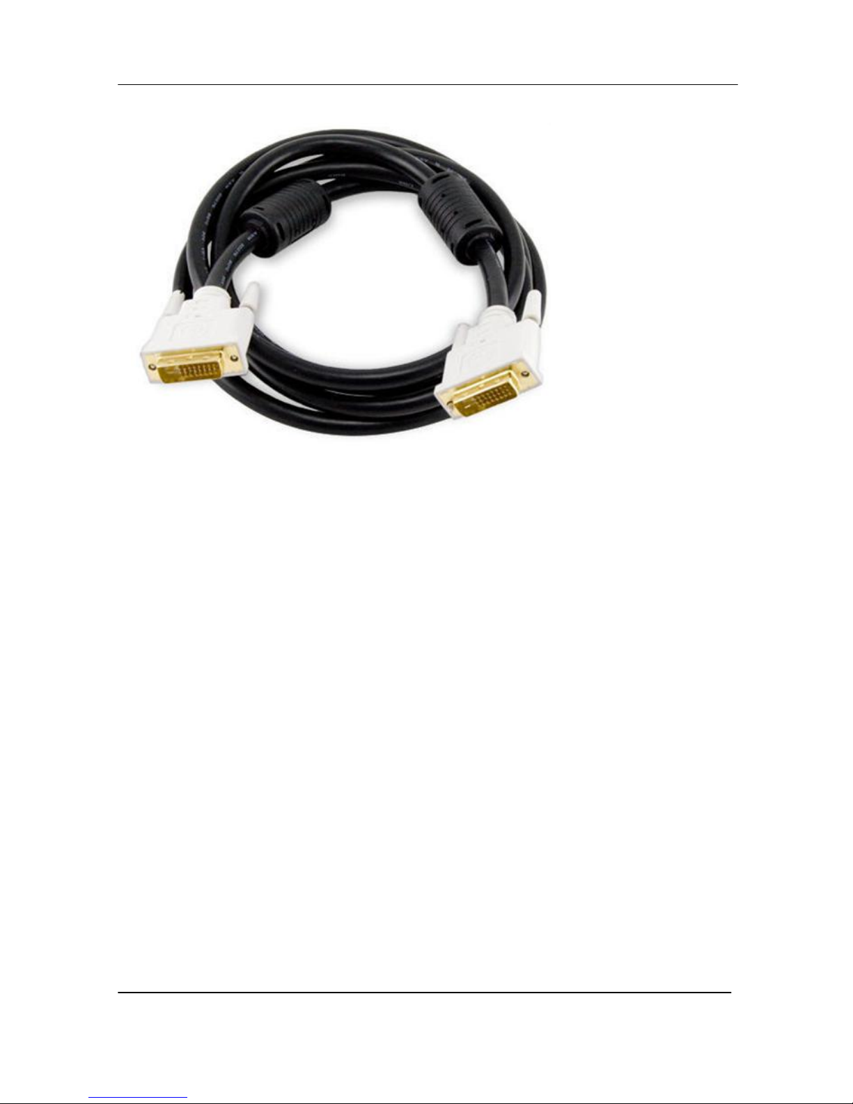
3.2.2 DVI to DVI Cable
Connects a DVI source to the DVI Broadcaster DL’s DVI port. This cable is included
with the DVI Broadcaster DL.
Page 13
Physical Attributes
9
DVI Broadcaster DL User Guide
Figure 4 DVI to DVI Cable
Page 14

Physical Attributes
10
DVI Broadcaster DL User Guide
3.2.3 HDMI to DVI Adapter
Connects an HDMI source to either of the DVI Broadcaster DL’s DVI ports. This
adapter is included with the DVI Broadcaster DL.
Figure 5 HDMI to DVI Adapter
3.2.4 RJ-45 Male
Connects the DVI Broadcaster DL to an Ethernet network.
Figure 6 RJ-45 Male Cable
Page 15

Getting Started
11
DVI Broadcaster DL User Guide
3.2.5 Power over Ethernet (PoE) Injector
The DVI Broadcaster DL incorporates a Power over Ethernet (PoE) technology. PoE
delivers both data and electrical power to an Ethernet enabled device using a single
Ethernet cable. This eliminates the need for the DVI Broadcaster DL to be situated
close to a power outlet. This allows more freedom in its placement.
PoE injectors supply or inject direct current (DC) power through network cables to
power network devices.
4 Getting Started
4.1 Supplying Power to the DVI Broadcaster DL
To provide power to the DVI Broadcaster DL, plug the provided PoE adapter into a
10/100Base-T Ethernet network using an Ethernet cable. This network must be
running the TCP/IP protocol.
If your network does not provide Power over Ethernet, connect the DVI Broadcaster
DL to an AC power outlet with the PoE adapter/injector connected to an Ethernet
cable and plugged into the DVI Broadcaster DL’s RJ45 Ethernet port.
Regardless of the power source once connected, the DVI Broadcaster DL now
powers up. Its power and activity LEDs will now light up following their start up
sequence.
4.2 Confirm Input Signal is Received
Confirming that the input signal is being received by the DVI Broadcaster DL can be
done once the DVI Broadcaster DL has been powered on and the input source has
been started.
First, check that the DVI Broadcaster DL’s red LED is blinking. A blinking LED
indicates that the DVI Broadcaster DL is capturing images. If the red LED does not
start flashing, check the input source to ensure that it is transmitting a signal.
Additionally, check that a cable from the input source to the DVI Broadcaster DL is
connected correctly.
Note that you can check whether the DVI Broadcaster DL is transmitting an audio
signal only in a live stream or when you open a recorded file.
Page 16

Getting Started
12
DVI Broadcaster DL User Guide
4.3 Network Connections
Please to refer to the Networking chapter for the instructions on direct DVI
Broadcaster DL’s connection to the Ethernet, discovering the DVI Broadcaster DL on
the network, IP address settings and other details.
4.4 Logging into the Web Admin Interface
The Web admin Interface is accessible by logging into it using one of the following
methods.
4.4.1 Access through Service Discovery
The multicast Domain Name System (mDNS) is a zero configuration host name
resolution service. It allows a user to do without an IP address when performing
access to the device. Bonjour software installed on a Windows or Mac machine
supports mDNS.
To access the device through service discovery, the following conditions should be
met depending on your OS:
Microsoft Windows – you must install Bonjour Print Services as explained below.
To install Bonjour Print Services on a Windows machine:
1. Use the following URL - http://support.apple.com/kb/DL999
2. Click Download.
3. Follow the system prompts to download the application on your computer.
MacOS X – Bonjour software which is used for service discovery comes built-in with
Mac OS. Therefore DVI Broadcaster DL device can be accessed without any
additional installations.
Linux – the Avahi implementation used for service discovery is shipped with most
Linux distributions. Therefore most probably your device will be accessed without
any additional installations. However you are recommended to address your
administrator for the details first.
The simplest way to access Web Admin interface of your DVI Broadcaster DL in the
local network is to type the following string in the address bar of your web browser:
Page 17

Getting Started
13
DVI Broadcaster DL User Guide
<serial>.local
where <serial> is the serial number of your DVI Broadcaster DL.
For example: http://92033.local
4.4.2 Epiphan’s Network Discovery Utility.
The Epiphan Network Discovery Utility can be installed and executed from a
workstation running Windows XP, Vista or Windows 7. Follow the following steps to
access the Web admin Interface through this utility:
1. Start the Epiphan Network Discovery Utility tool.
2. Click Search to find all of the Epiphan devices on the network and select the
desired DVI Broadcaster DL.
3. Click Web config.
4. A web browser starts and you are prompted for the DVI Broadcaster DL’s
administrator user name and password.
5. Enter the following information:
User Name: admin
Password: configured password<return>, there is no default password so unless
a password has been configured, just hit <return>
The Web admin interface opens.
Alternatively the Network Discovery Utility can be used to retrieve the DVI
Broadcaster DL’s IP address and access to the Web admin Interface will be done
using a browser.
4.4.3 Logging into the Web Admin Interface Using a Web Browser and the
IP Address of the DVI Broadcaster DL
The web browser can be running on Windows, Mac OS X, Linux or any other
operating system.
1. Start a web browser on any workstation connected to the same network as
the DVI Broadcaster DL.
2. Browse to the DVI Broadcaster DL.
http://<ip address of the DVI Broadcaster DL>/admin
The IP address of the DVI Broadcaster DL can be obtained using any of the
following methods:
a. The Epiphan Network Utility
Page 18

Getting Started
14
DVI Broadcaster DL User Guide
b. The EpiphanTouch app
c. From the network administrator
d. Using the Factory Default static IP address. Only if the steps in
section, Connecting Directly to the DVI Broadcaster DL, are
followed
3. Log in as the DVI Broadcaster DL’s administrator user
User Name: admin
Password: configured password<return>, there is no factory default
password so unless a password has been configured, just hit <return>
The Web admin Interface opens.
4.5 Users Logging
The DVI Broadcaster DL comes with three pre-configured users which can log in the
control interface. The first is the administrator user, the user name is admin. The
second is the operator user, the user name is operator. The third is the viewer user,
the user name is viewer. Each can be assigned a password but their user names
cannot be altered. It is not possible to create new user names.
Important: When you install firmware for the first time after purchasing the device,
no default passwords are set.
4.5.1 The Administrator User
The administrator user is granted rights to log into the DVI Broadcaster DL and
perform any of the following functions:
1. Perform configuration changes to the DVI Broadcaster DL.
2. Manage the current broadcast. This can include the starting or stopping of the
recording of the broadcast.
3. Manage previously recorded broadcasts. Including the archiving of recordings.
4. System monitoring. This would involve retrieving any system statuses and
retrieving the solid state memory status.
5. Upgrading the System Firmware from Epiphan Support. New firmware is
released to fix known problems or to add new features.
6. Perform network diagnostics.
Page 19

Getting Started
15
DVI Broadcaster DL User Guide
As a default factory setting, the administrator user does not come with a password
but it is recommended that a password is configured as early as possible for security
reasons.
4.5.2 The Operator User
The operator user is granted rights to log in to manage broadcast recordings,
configure audio and frame grabber settings, access the recorded files and perform
network diagnostics.
As a default, the operator user does not come with a factory configured password.
Configuring an operator password is optional.
4.5.3 The Viewer User
The viewer user is granted rights to log in to view broadcasts and does not have any
administrative ability.
As a default, the viewer user does not come with a factory configured password.
Configuring a viewer password is optional.
4.6 Web Admin Interface
In this section you can see a diagram showing the Web admin Interface’s main
menu. It is located on the left side of the screen.
Page 20

Getting Started
16
DVI Broadcaster DL User Guide
Figure 7 Web Admin Interface's Main Menu
Page 21

Getting Started
17
DVI Broadcaster DL User Guide
The following table briefly describes each of the options on the Web admin
Interface’s main menu.
Table 3 Web admin Interface’s Main Menu Options
Stream Setup
Change the stream settings.
Publish Stream
Sends the stream to a remote streaming server such as a Content
Distribution Network service provider (CDN) or Epiphan.tv portal
Stream
Branding
Customize the recording and broadcast: specify the information
that is displayed to a viewer and select the logo and “No signal”
image.
UPnP
Access recorded files and streams on the local network using a
media player via the UPnP protocols.
Frame Grabber
Make frame grabber image adjustments.
Audio
Change and adjust the audio input.
Automatic File
Upload
Set up automatic files uploading from the DVI Broadcaster DL
device to a network storage device.
FTP Server
Configure FTP access settings to connect to the DVI Broadcaster
DL internal solid state memory using an FTP client and the
administrator, operator or viewer account.
Network
Change the DVI Broadcaster DL network configuration.
Date and Time
Change DVI Broadcaster DL date and time settings.
Access
passwords
Change the admin, viewer and operator account password.
Serial Port
Integrate the DVI Broadcaster DL with other equipment featuring
an RS-232 port and control your device over the RS-232
connection.
Branding
Customize design of the browser where the broadcast is viewed.
Maintenance
Reboot or shut down the DVI Broadcaster DL device. Restore
factory configuration.
Disk Check
Set a Maintenance Schedule for checking the DVI Broadcaster DL
solid-state memory for errors.
Firmware
Upgrade
Upgrade the DVI Broadcaster DL firmware.
Info
Display information about the DVI Broadcaster DL Firmware and
hardware, broadcasting and recording status, available streams,
input video signal.
Disk Status
View the total solid state memory in GB, the used and available
hard solid state memory in GB, and also the amount used as a
percentage of the total solid state memory.
Page 22

Video Formats and Standards
18
DVI Broadcaster DL User Guide
5 Video Formats and Standards
The DVI Broadcaster DL supports broadcasting of various standards and formats.
The choice of video format will depend on the broadcast content and performance
requirements. For example, Motion JPEG does not support audio from an external
source. It also depends on how the intended viewers are planning to receive and
play the broadcast. Keep in mind that browser viewer capabilities and
compatibilities are subject to change.
With the DVI Broadcaster DL, video codec for streaming is selected by an
administrator. After this action the system creates a list of available streaming
formats for this codec. Users can view the broadcast in any available format
depending on their preference. Moreover, multiple users can view the same
broadcast in different formats. The list of formats available for the selected
combination of video and audio codecs displays on the Info page of the Web admin
interface.
The DVI Broadcaster DL can stream video using Flash (H.264), ASF (MPEG4 or H.264
codecs), Motion JPEG, RTSP (MPEG4 or H.264 codecs) or MPEG-TS (H.264). A quick
definition of these video streaming methods and the type of application that a
viewer would use to watch that particular video stream is now provided.
The Adobe Flash Video file type is proprietary but is supported on most web
browsers and on many media players including the VLC Media Player. This file type
supports the H.264 standard. This video supports analog audio from an external
source.
The Advanced System Format (ASF) file type also called Advanced Streaming
format, can be viewed with the Windows Media Player or the VLC Media Player.
Additional codecs may need to be installed to view ASF files. This file type supports
H.264 and MPEG4 standards. This video supports analog audio from an external
source.
The Motion JPEG file type records each frame in the video in JPEG format and can
be viewed using most web browsers. This video does not support analog audio from
an external source.
The RTSP type supports many media players including QuickTime and MPlayer. This
file type supports H.264 and MPEG4 standards. This video supports analog audio
from an external source.
Page 23

Signal Capture
19
DVI Broadcaster DL User Guide
The MPEG Transport Stream (MPEG-TS) type supports many software and hardware
media players. This stream type conforms to H.264 standards.
Note: Media Player, browser, viewer capabilities and compatibilities are subject to
change.
6 Signal Capture
6.1 Connecting Input Sources
It is recommended that prior to powering up the DVI Broadcaster DL, the input
source is connected first. This input source can be a DVI or HDMI source. Any one of
these sources would be connected to the DVI Broadcaster DL using its DVI input
port. Audio input will be connected to the DVI Broadcaster DL Audio in port.
6.1.1 Connecting DVI or HDMI Input Sources
All DVI or HDMI input sources are connected to the DVI Broadcaster DL using the
DVI input port. How this connection is made and using which cable is dependent on
the input source.
DVI input sources are connected using the DVI to DVI cable.
HDMI input sources are connected using the HDMI to DVI adapter. These sources
should only be non-copy protected content.
Note that an HDMI signal containing audio will not be captured.
6.1.2 Connecting Audio Input Sources
All audio sources are connected to the DVI Broadcaster DL using the audio input
port.
6.2 Frame Grabber Adjustments
A frame grabber is an electronic device that captures individual still frames from a
digital video stream and transmits them in a digital form. An Epiphan frame grabber
is a subsystem component in the DVI Broadcaster DL and can be configured
separately. From the Web admin interface, select Frame Grabber from the main
menu to configure Frame Grabber adjustments.
Page 24

Signal Capture
20
DVI Broadcaster DL User Guide
Normally, making manual image adjustments should not be necessary. This means
that there are no default Frame Grabber adjustment settings. However, special
requirements may exist that produce image quality problems that can only be fixed
by making image adjustments.
The Frame Grabber adjustments page within the Web admin interface contains
most of the information needed to make image adjustments. This includes a brief
description of the effect created as a result of each adjustment and the adjustment
range.
To make an adjustment, add a value to one or more fields and select Apply.
To clear any adjustments, delete the value from one or more fields and select Apply.
Page 25

Signal Capture
21
DVI Broadcaster DL User Guide
Figure 8 Frame Grabber Adjustments
Page 26

Signal Capture
22
DVI Broadcaster DL User Guide
The table below discusses all options found on the Frame Grabber Adjustment page.
Table 4 Frame Grabber Adjustment Options
Interval between
VGA signal
autoadjustments,
sec
Change the interval between automatic adjustments if you
want them to occur more or less often. To suspend
automatic adjustments, enter 0.
Vertical shift
Configure the vertical shift to offset the captured image’s
position. For example, a captured image that is shifted
slightly downward or vertically can be corrected with minor
adjustments to the vertical shift settings.
Increasing or decreasing the value entered in the Vertical
Shift field shifts the image up or down.
Horizontal shift
Configure the horizontal shift to offset the captured image’s
position. For example, a captured image that is shifted
slightly to the right or horizontally can be corrected with
minor adjustments to the horizontal shift settings.
Increasing or decreasing the value entered in the Horizontal
Shift field shifts the image to the right or left.
Phase
Not used.
PLL adjustment
Not used.
Offset
Not used.
Gain
Not used.
Aspect ratio
Not used.
Select EDID file
Browse to the Extended display identification data (EDID) file
to be uploaded.
EDID is the information about display’s supported
resolutions, timings, formats, chromacity, and other media
parameters. This information can be used by a signal source
for adaptation to the characteristics of a device accepting the
signal.
Use this URL to upload EDID files:
http://www.epiphan.com/downloads/edid/
Page 27

Stream Setup
23
DVI Broadcaster DL User Guide
7 Stream Setup
When you log in to the control interface, in the Stream Setup section you can
configure the video codec and specify streaming settings for the input signal.
7.1 Select Video Codec
Before starting the video recording or broadcasting process, you have to specify the
video codec for encoding. It can be selected in the Stream Setup section of the
interface.
To select the video codec:
1. Click the Stream Setup option.
2. Click an arrow in the Codec field.
3. Select the required codec from the drop-down list. The following values are
available for selection:
H.264
MPEG4
Motion JPEG
After you have specified required video and audio codecs (as described in this
section and in the Select Audio Format section), click the Info menu option of the
Web Admin interface to see available broadcasting formats for your settings and
obtain the IP addresses for the broadcast (refer to Retrieving the Stream’s URL for
Broadcasting).
Figure 9 Stream Settings
Page 28

Stream Setup
24
DVI Broadcaster DL User Guide
Table 5 Stream Setup settings
Video encoding preset
Defines how a video stream should be encoded:
- at a high quality
- at a high speed
- according to the default system settings.
Video encoding profile
Select one of the following encoding profiles that target
specific classes of applications:
1. Baseline: for applications requiring additional
data loss robustness, e.g. videoconferencing
2. Main: for standard-definition broadcasts
3. High: for broadcast and disc storage
applications
This parameter can be set for the H.264 codec only.
Enhanced compatibility
mode (h.264 slicing for
RTP)
This parameter provides operating stability if the
transmitted video/audio stream is not quite supported
by the viewer’s equipment.
When this parameter is activated, each picture is
subdivided into one or more slices. The slice is given
increased importance in H.264 as the basic spatial
segment that is independent from its neighbours. Thus,
errors or missing data from one slice cannot propagate
to any other slice within the picture.
The following streaming settings can be made:
Figure 10 Streaming Settings
Page 29

Stream Setup
25
DVI Broadcaster DL User Guide
Below is a table showing the streaming settings that are configurable.
Table 6 Streaming settings
Show time label
If the video needs to be time labeled or timestamped, this
parameter allows how the date and time will be displayed.
Click on Show substitutions and use the Format
substitutions commands to select the desired date and
time format. The commands are described in a table
below.
If time labeling is not required, leave this field blank.
Frame size
Select a frame size from the drop down list to limit the
width and height of the video image. If the video source is
sending resolutions larger than the resolution limit
configured, the video image will be scaled to the
resolution limit. Limiting the frame resolution can help to
reduce bandwidth usage.
Key frame interval
Controls the number of frames. Key frames define the
starting and ending points of any smooth transition.
Limit frame rate
Enter a value in terms frames per second. This field is
used to set a frame rate that is lower than the maximum
frame rate at which the DVI Broadcaster DL can capture
images. Reducing the frame rate reduces the number of
images being captured by the device. Decreasing the
frame rate can help to reduce bandwidth usage.
Bitrate
Enter a DVI signal bitrate. A lower bitrate produces lower
quality videos and smaller file sizes. A higher bitrate
produces better quality videos and larger file sizes.
Quality parameter (for
MJPEG only)
This parameter is similar to Bitrate. Use bigger values to
improve the quality of the broadcast.
Table 7 Format Substitutions Commands
Command
Value
Example (27/09/2012
10:50:45.378)
date
%F
2012-09-27
year
%G
2012
month (as 01)
%m
09
month (as
%b
Sep
Page 30

Stream Setup
26
DVI Broadcaster DL User Guide
Jan)
month (as
January)
%B
September
day of month
%d
27
weekday (as
Thu)
%a
Thu
weekday (as
Thursday)
%A
Thursday
time
%T
10:50:45
hour
%k
10
minute
%M
50
second
%S
45
ms
%#m
378
7.2 Audio Configuration
Use the Audio section of the Web admin interface to configure the audio settings
that control the audio input. All available video formats support audio except
Motion JPEG.
Figure 11 Audio Configurable Options
Table 8 Audio Configurable Options
Input Source
Select the input source
Line
Mic (pre-amplified signal)
Input Amplifier Volume
Reduce the input volume if the line in signal volume is
Page 31

Stream Setup
27
DVI Broadcaster DL User Guide
too high for the DVI Broadcaster DL line in amplifier. The
default input amplifier volume setting is 30%. If the input
volume is too high, change the setting to between 5%
and 90% to reduce the input volume.
7.3 Common Settings
The following common parameters can be additionally specified:
Table 9 Common settings
Rate control mode
Used for H.264 and MPEG4 codecs. It specifies the
bitrate encoding for the signal. Select one of the
following:
- Low Delay
Means Constant Bitrate Encoding (CBR) will be used.
CBR is useful for streaming multimedia content on
limited capacity channels since it is the maximum bit
rate that matters, not the average. Therefore, CBR
would be used to take advantage of all of the
channel capacity.
- Storage
Means Variable Bitrate Encoding (VBR) will be used.
This produces a better quality-to-space ratio
compared to a CBR file of the same data. VBR files
vary the amount of output data per time segment
and the FPS value may be lower.
Stream port
The number of the port being used to stream the
broadcast. This value would be used along with the URL
to access the broadcast. In the case where there are two
streams because Independent streaming is being used,
this value remains the same for both of the URLs being
used.
In case of RTSP streaming this value is not considered.
Page 32

Stream Setup
28
DVI Broadcaster DL User Guide
Figure 12 Common Settings
The Page refresh time parameter in the MJPEG webpage section is available if the
Motion JPEG codec is selected.
Page refresh time
Specify how often the browser updates
the visual information coming from the
DVI Broadcaster DL. In other words, how
often the page is refreshed
7.4 Select Audio Format
The Audio settings pane in the control interface can be accessed by clicking the
Stream Setup option from the menu. Select the Enable audio checkbox and specify
the audio signal parameters.
Table 10 Audio settings
Enable audio
Select this checkbox to enable audio for
the broadcast.
Audio format
You can select the following audio
formats:
MP3 – a common audio format
for consumer audio storage
Raw PCM (Pulse Code
Modulation) – a standard form
for digital audio in computers
as well as other uses such as
digital telephone systems
G.711 – an ITU-T standard for
audio companding. It is a very
commonly used waveform
Page 33

Streaming
29
DVI Broadcaster DL User Guide
codec.
o μ-law is used primarily
in North America
o A-law is in use in most
other countries
outside North America
AAC - a standardized, lossy
compression and encoding
scheme for digital audio. AAC
generally achieves better sound
quality than MP3 at similar bit
rates.
Audio channels
Select either mono (1 channel) or stereo
(2 channels) sound.
Audio bitrate
Select the audio bitrate value for the
broadcast.
Figure 13 Audio Settings
8 Streaming
There are several decisions that need to be made when planning the creation of a
broadcast, besides its exact content of the broadcast. Will the broadcast include an
audio component coming from an analog audio source? What video format to use,
what video standard to use, how to stream the broadcast are all questions that have
to be answered when creating a broadcast. Most of the answers depend on the
intended audience of the broadcast, how are the viewers going to view the
broadcast, and how many simultaneous viewers are expected to view the
broadcast? Where are the viewers located in relation to the where the broadcast is
Page 34

Streaming
30
DVI Broadcaster DL User Guide
being streamed? What are the performance expectations? These are the types of
questions that will determine the overall design of the broadcast.
This chapter outlines how a suitable design of a broadcast can be architected based
on these types of questions and their resulting answers and how the System can be
used in this design.
The DVI Broadcaster DL supports streaming of various standards and formats. The
choice of video format will depend on the broadcast content and performance
requirements. For example, Motion JPEG does not support audio from an external
source. It also depends on how the intended viewers are planning to receive and
play the broadcast. Keep in mind that browser viewer capabilities and
compatibilities are subject to change.
With the DVI Broadcaster DL, video codec for streaming is selected by an
administrator. After this action the system creates a list of available streaming
formats for this codec. The figure below is representation of the protocol stack
diagram showing how the video data is processed.
Figure 14 Protocol Stack Diagram
How the broadcast will be delivered to its viewers depends on the number of
intended viewers and where the viewers are in relation to where the broadcast is
originating. Are they on the same LAN or will they be accessing the broadcast from
Page 35

Streaming
31
DVI Broadcaster DL User Guide
an external network? The answers to the above questions will help decide the
delivery method of the broadcast.
The DVI Broadcaster DL can support streaming over HTTP, RTSP, peer-to-peer RTP
connection, multicast RTP, MPEG-TS, and a Content Distribution Network (CDN)
broadcast network. Each broadcast delivery method will be now discussed in more
detail.
8.1 HTTP or RTSP Streaming
For HTTP or RTSP streaming the only information required to view the broadcast is
the URL of the broadcast. The DVI Broadcaster DL is ready to go straight out of the
box, without any additional settings. If your broadcast needs to be accessed by
many clients, use a Content Distribution Network as explained in the Using a
Content Distribution Network section.
8.2 Using a Content Distribution Network
A content delivery network (CDN) is a system of computers or servers that ingest an
incoming stream source and rapidly provides this content to numerous users by
duplicating the content on multiple servers and directing the content to users.
CDN distributes a heavy load of traffic to multiple locations in order to avoid
congestion on a network that could impact a user’s Internet experience. A CDN is
highly scalable and can make financial sense to website owners as you will not need
to pay for additional server hardware or routing should your website traffic start to
increase or even decrease. The use of CDN technology has obvious advantages to
those users whose broadcasts have large audiences from locations all over the
world. If dozens or hundreds of viewers happen to select the same Web page or
content simultaneously, the CDN sends the content to each of them without delay
or time-out.
To stream to multiple users, the System can be configured as a client to CDN. Please
click http://epiphan.tv/cdn-partners.php to view the list of CDN providers preferred
by Epiphan. By connecting to a CDN server, the broadcast from the DVI Broadcaster
DL can be streamed to multiple viewers. By using a CDN, the maximum number of
Page 36

Streaming
32
DVI Broadcaster DL User Guide
concurrent clients is increased, while at the same time reducing the load on the
uplink internet connection.
CDN streaming is a very effective approach when you are broadcasting streams from
the Epiphan solutions and want to add scalability to your broadcast. The DVI
Broadcaster DL features the Publish Stream functionality that enables you to stream
the broadcast either via Epiphan’s portal or CDN providers to multiple viewers. You
must use the H.264 codec for CDN streaming.
Using CDN it is possible to set a user name and a password for the broadcast. Each
viewer will have to request it from you before viewing the broadcast. This function
allows you to manage access to your content ensuring visibility only to the
appropriate and authorized viewers.
Figure 15 Using a CDN Service Increases Scalability of Concurrent Viewers
The Publish Stream functionality allows for directing captured video and audio to
servers or clients using one of the available stream modes. The following options are
available:
- Disabled. If this option is enabled, you cannot send multicast RTP stream,
perform CDN broadcasting or stream video to Epiphan’s portal.
Page 37

Streaming
33
DVI Broadcaster DL User Guide
- to xxxxx.epiphan.tv. This option allows for streaming video to the
Epiphan’s portal.
- using RTSP announce. This option allows for connecting to CDN server.
- using RTP/UDP push. This option allows for IP multicast broadcasting.
- using MPEG-TS UDP push. This option allows for IP multicast broadcasting
of files in the MPEG-TS format in case when the UDP transportation
protocol is used.
- using MPEG-TS RTP/UDP push. This option allows for IP multicast
broadcasting of files in the MPEG-TS format in case when the RTP/UDP
transportation protocol is used.
These options and settings to be performed are discussed further.
The Publish Stream functionality is available only for the H.264 video codec.
8.2.1 Using Epiphan.tv Portal for Streaming
To set up and perform streaming via Epiphan.tv portal:
1. Click the Publish Stream option in the main menu of the control interface.
2. Select to xxxxx.epiphan.tv from the Publish drop-down list where xxxxx is
the unique serial number of the DVI Broadcaster DL.
3. Select Enable publishing and click Apply. The system informs you that
stream will be available on the Epiphan’s portal and provides a link.
Figure 16 URL to Epiphan Server
4. Click this link and access the portal where the stream is being broadcast in
a new window.
5. In case you have selected a codec other than H.264 for streaming (MPEG4
or Motion JPEG), the system will give you a warning (see Figure 17 System
Message in Case of Excessive Bitrate Speed). Click on fix by setting H.264
codec. The codec will be set to H.264 automatically.
Page 38

Streaming
34
DVI Broadcaster DL User Guide
6. In case the bitrate of your broadcast exceeds 500 kbit/s, the system will
give you a warning (see Figure 17 System Message in Case of Excessive
Bitrate Speed). Click on fix by reducing bitrate to 500 kbit/s. The bitrate
will be set to 500 kbit/s automatically.
Note: Epiphan.tv is a demonstration service to help customers experiment
with publishing streams to content distribution networks. Therefore
certain bandwidth and performance limits are applied. To upgrade to a full
service please select one of Epiphan’s CDN partners.
Figure 17 System Message in Case of Excessive Bitrate Speed
Figure 18 System Message after Setting H.264 codec and Reducing Bitrate
Now connection through the media tunnel is established. The DVI Broadcaster DL
starts streaming to the Epiphan’s portal – epiphan.tv.
It is required to set up audio format as MP3 when streaming through the epiphan.tv.
This setting is performed in the control interface’s Stream Setup section (see Select
Audio Format).
There are several buttons available at the bottom of the epiphan.tv portal page (see
Figure 19 Epiphan’s Portal):
Switch to
Click this button to select a plugin which will be used for viewing the
stream. Refer to Figure 20 Plugins Available for Selection on the
Portal.
The following plugins are available:
- Flash RTMP
Page 39

Streaming
35
DVI Broadcaster DL User Guide
- Flash HTTP
- QuickTime
- VLC Player
Embed
Displays a code that allows you to embed video stream into your
web page. Refer to Figure 21 Code for Stream Embedding.
Direct URL
Displays a list of URLs for different types of broadcasting. Refer to
Figure 22 Listing of Direct URLs.
7. Click Switch to button and select a plugin for viewing the stream.
8. If you need to embed the stream into your web page, click Embed to
obtain the code.
9. Click Direct URL to obtain the list of URLs for different types of
broadcasting.
Figure 19 Epiphan’s Portal
Page 40

Streaming
36
DVI Broadcaster DL User Guide
Figure 20 Plugins Available for Selection on the Portal
Figure 21 Code for Stream Embedding
Figure 22 Listing of Direct URLs
Alternatively you can configure DVI Broadcaster DL to stream their content through
epiphan.tv directly on the portal.
To view the stream directly on the portal:
1. Type http://epiphan.tv in the address bar of your browser.
2. Enter serial number of DVI Broadcaster DL. It is displayed in the Info
section of the Web admin interface.
3. Click the Go! button.
Page 41

Streaming
37
DVI Broadcaster DL User Guide
8.2.2 Using Epiphan’s Partners as CDN Providers For Streaming
Use this option if you need to perform streaming on a remote streaming server
other than epiphan.tv. Please contact CDN support to request the list of supported
audio codecs and perform the required setting in the control interface’s Stream
Setup section (see Select Audio Format).
To use this option:
1. Select RTSP Announce from the drop-down list.
2. Enter the host/server name. For example, 172.20.1.50.
3. Enter the number of port which is used for streaming to server. Usually for
RTSP streaming it is port 554.
4. In the Mount point field enter the full path to locate an SDP file on server.
This path is provided by the CDN provider.
5. The RTSP protocol uses UDP or TCP as transport layers. If your CDN service
requires TCP as a transport layer, select the Use TCP for RTP stream check
box.
6. If necessary, enter the user and password information.
7. Click Apply.
Figure 23 RTSP Announce Functionality
Page 42

Streaming
38
DVI Broadcaster DL User Guide
8.2.3 Setting up Multicast from Publish Stream
A multicast RTP stream provides a one-to-many broadcasting framework. In a
multicast RTP configuration, the DVI Broadcaster DL sends a packet only once to a
router that supports multicasting. This router then distributes the packets to all
intended viewer nodes using a multi-cast protocol.
A multicast address is associated with a group of interested receivers. In IPv4,
addresses 224.0.0.0 through 239.255.255.255 (the former Class D addresses) are
designated as multicast addresses.
Sending multicast streams requires equipment that supports multi-casting,
configuring your network and enabling specific multicasting features on the DVI
Broadcaster DL. Multicast architectures are used predominantly within a high
bandwidth corporate LAN and not on Internet based architectures. Multicast RTP
streaming is not usually propagated outside the LAN though it may be propagated
through VPNs connecting several LANs. Multicast transmission is available during
RTP streaming.
RTP/UDP Push streaming allows you to direct video to a server or client and
generates an SDP file containing the stream description. SDP files can be stored on a
streaming server, or opened by video players.
To use this option:
1. Select Publish Stream from the main menu.
2. Select RTP/UDP Push from the drop-down list.
3. Enter a destination multicast IP address. At this target point the broadcast
will be viewed.
4. Specify the numbers of the video and audio ports where the broadcast will
be received.
5. Click Apply.
6. An SDP file is now generated. It is available in the Info section of the Web
Admin interface. You can either save an SDP file on your local machine or
provide the link to SDP file to your audience.
Page 43

Streaming
39
DVI Broadcaster DL User Guide
Figure 24 RTP/UDP Push Functionality
8.2.3.1 RTP/UDP Push streaming for the MPEG-TS file format
The Web interface allows you to set up the MPEG-TS stream using MPEG-TS for
RTP/UDP Push and MPEG-TS for UDP Push options. These options are used, for
example, when you need to add a DVI Broadcaster DL’s stream to an IP TV or set-top
box’ playlist.
To use the RTP/UDP Push streaming, you must configure the following streaming
settings in the Web Admin interface:
Video codec
H.264
Audio codec
MP3 or AAC
Using the first of these options it is possible to configure RTP/UDP transporting for
the MPEG-TS stream.
To use this option:
1. Select Publish Stream from the main menu.
2. Select using MPEG-TS for RTP/UDP Push from the drop-down list.
3. Enter a destination multicast IP address. At this target point the broadcast will
be viewed.
4. Specify the number of the destination port where the broadcast will be
received.
5. Click Apply.
Page 44

Streaming
40
DVI Broadcaster DL User Guide
Figure 25 MPEG-TS UDP Push Functionality
To view the stream you need a link: rtp://@ip:port (for example,
rtp://@226.63.45.23:6000).
To get the link for the stream, select the Info section of the Web admin interface
and view the Stream Info pane.
8.2.3.2 UDP Push streaming for the MPEG-TS file format
To configure UDP transporting for the MPEG-TS stream, select using MPEG-TS for
UDP Push from the drop-down list.
To use the UDP Push streaming, you must configure the following streaming settings
in the Web Admin interface:
Video codec
H.264
Audio codec
MP3 or AAC
To use this option:
1. Select Publish Stream from the main menu.
2. Select using MPEG-TS for UDP Push from the drop-down list.
3. Enter a destination multicast IP address. At this target point the broadcast
will be viewed.
4. Specify the number of the destination port where the broadcast will be
received.
5. Click Apply.
Page 45

Streaming
41
DVI Broadcaster DL User Guide
Figure 26 MPEG-TS RTP/UDP Push Functionality
To view the stream you need a link: udp://@ip:port (for example,
rtp://@226.63.45.23:6000).
To get the link for the stream, select the Info section of the Web admin interface
and view the Stream Info pane.
8.3 UPnP
The DVI Broadcaster DL supports a set of networking protocols named Universal
Plug and Play (UPnP). It allows you to discover a presence of the functioning DVI
Broadcaster DL on the network using a device such as media player connected to a
TV set. Once the DVI Broadcaster DL is connected to a network, it automatically
establishes working configuration with the media player and can share the data
stream.
To use the UPnP functionality, you must configure the following file and streaming
settings in the Web Admin interface:
Video codec
H.264
Audio codec
MP3 or AAC. Alternatively you may configure UPnP without
selecting any audio codec.
File type
MPEG-TS – to obtain access to the files recorded earlier.
This functionality is enabled in the UPnP section of the Web Admin interface. The
media player identifies the DVI Broadcaster DL as a media server. In the
explanations below the UPnP settings are illustrated by the example of the media
player Asus O!Play.
To establish UPnP connection:
1. Set up the DVI Broadcaster DL and start streaming/recording.
Page 46

Streaming
42
DVI Broadcaster DL User Guide
Make sure the viewer password is not set up.
2. If necessary, in the UPnP section use the Server field to name the media
server (DVI Broadcaster DL).
You can use the following characters: A-Z, a-z, 0-9, _, :, @, ^, #, -. {}, [], ().
3. In the UPnP section select the Share live video through UPnP checkbox if
you want to share live video streaming only.
4. Select the Share recorded files through UPnP checkbox if you want to
share recorded files only.
If none of these check boxes is selected, the media server will not be
displayed on the local network.
5. Connect your media player to your TV set.
6. Power on the media player and select the UPnP option in the player’s
interface.
Figure 27 UPnP Option in the Media Player’s Interface
7. Select the media server.
The media player displays either Live Streams or Recorded Files folder
depending on settings (see steps 3 and 4). In case both check boxes were
selected, both folders will be visible.
Page 47

Streaming
43
DVI Broadcaster DL User Guide
Figure 28 Live Streams and Recorded Files Folders
8. Select the folder and the required stream or recorded file. All files are
sorted by date (Last 24 hours, last month, last week, older).
Figure 29 Sorted Files in the Folders
Page 48

Streaming
44
DVI Broadcaster DL User Guide
Figure 30 Selecting Live Stream
V
8.4 Viewing Streaming Video
The DVI Broadcaster DL may capture DVI or HDMI video signals in resolutions up to
2048x2048 or 2560x1600 for widescreen applications.
Viewers can access the broadcasted video streams with a web browser that
supports Motion JPEG, MPEG4 or Flash Video/H.264 compression or with a media
player that is compatible with the stream format being transmitted. The available
video stream formats is determined by selected video codec. Audio is available for
all formats except from Motion JPEG.
8.4.1 Retrieving the Stream’s URL for Broadcasting
In order for viewers to log in and view a stream, the administrator must release the
URL(s) of the stream. The administrator is able to provide separate URLs for the
stream coming in from the DVI Broadcaster DL video input ports and audio input
ports. Alternatively, one URL can be provided that includes all the streams from all
input sources. The administrator can retrieve the appropriate stream URL or URLs
as explained below.
8.4.2 Using the Web Admin Interface’s Info Page
The following indicates where each URL for the broadcast can be found on that
page:
Live broadcast is the URL for the broadcast from a video source and an audio port.
Page 49

Streaming
45
DVI Broadcaster DL User Guide
The URLs for the broadcast in all available formats are also shown in the Stream Info
section.
See an example below.
Figure 31 URLs of the Broadcast Displayed in the Stream Info Section
8.4.3 Using the Web Admin Interface’s Live View Feature
The second method for retrieving the desired broadcast URLs is to use the Web
Admin interface’s Live View Feature. This feature not only shows the current
broadcast to the administrator but also provides the broadcast URL. By clicking on
the Live View button from the main menu, a preview of the current broadcast’s
videos appear in the web browser. Under the broadcast screen the system displays
the URL of the broadcast.
Page 50

Streaming
46
DVI Broadcaster DL User Guide
Figure 32 A Broadcast with its URL Displayed Under the Broadcast Image
8.5 Viewing a Broadcast with a Browser
If the administrator has configured a viewer password, participants must obtain the
password in order to log in. The administrator will also provide the IP Address or the
URL to be used by the viewer’s browser.
To log in to view the broadcast using a browser:
1. Start any web browser.
2. Browse to the IP address of the DVI Broadcaster DL’s broadcast stream. For
example, if the IP address of the DVI Broadcaster DL’s broadcast is
172.20.1.33, then browse to: http:// 172.20.1.33
3. Enter the following:
User Name: viewer
Password: (enter the viewer password).
4. Press Enter.
5. The broadcast begins to play within the viewer’s browser.
Page 51

Streaming
47
DVI Broadcaster DL User Guide
Figure 33 Viewing a Broadcast Using a Web Browser
8.6 Viewing a Broadcast with a Media Player
If the administrator has configured a Viewer password, participants must obtain the
password in order to log in. The administrator will also provide the IP Address or the
URL to use within the media player.
To log in to view a stream using a media player:
1. Launch the media player.
2. Use the Menu bar to open the URL dialog box and enter the URL address of
the stream.
3. When prompted, enter the following:
a. User name: viewer
b. Password: enter the viewer password.
c. Press Enter.
4. The stream begins to play within the viewer’s player.
Page 52

Streaming
48
DVI Broadcaster DL User Guide
8.7 Compatibility Information
This section provides information on compatibility of video streaming formats and
player which is necessary for streaming video.
The DVI Broadcaster DL can stream video using Flash (H.264), ASF (MPEG4 or H.264
codecs), Motion JPEG or RTSP (MPEG4 or H.264 codecs). A quick definition of these
video streaming methods and the type of application that a viewer would use to
watch that particular video stream is now provided.
The Adobe Flash Video file type is proprietary but is supported on most web
browsers and on many media players including the VLC Media Player. This file type
supports the H.264 standard. This video supports analog audio from an external
source.
The Advanced System Format (ASF) file type also called Advanced Streaming
format, can be viewed with the Windows Media Player or the VLC Media Player.
Additional codecs may need to be installed to view ASF files. This file type supports
H.264 and MPEG4 standards. This video supports analog audio from an external
source.
The Motion JPEG file type records each frame in the video in JPEG format and can
be viewed using most web browsers. This video format does not support analog
audio from an external source.
The RTSP type supports many media players including QuickTime and MPlayer. This
file type supports H.264 and MPEG4 standards. This video supports analog audio
from an external source.
MPEG-TS is a standard format for transmission and storage of audio, video, and
Program and System Information Protocol (PSIP) data. It is used in broadcast
systems such as DVB, ATSC and IPTV. It supports such media players as MPlayer, VLC
Media Player, KMPlayer,
The following table displays the compatibility between the video/audio codecs and
the file formats during data streaming.
Page 53

Streaming
49
DVI Broadcaster DL User Guide
Video
codec
selected
Audio
codec
selected
RTSP
FLV
ASF
MPEG-TS
MJPEG
H.264
No audio
codec
+ + + + -
H.264
LPCM
+ + + - -
H.264
G.711
+ - + - -
H.264
MP3
+ + + + -
H.264
AAC
+ + + + -
MPEG-4
No audio
codec
+ - + - -
MPEG-4
LPCM
+ - + - -
MPEG-4
G.711
+ - + - -
MPEG-4
MP3
+ - + - -
MPEG-4
AAC
+ - + - -
MJPEG
No audio
codec
- - - - +
The following table displays the compatibility between the video/audio codecs and
the file formats during data recording.
Video
Audio
AVI
MOV
MPEG-TS
H.264
No audio
codec
+ + +
H.264
LPCM
+ + -
H.264
G.711
+ + -
H.264
MP3
+ + +
H.264
AAC
+ + +
MPEG-4
No audio
codec
+ + -
MPEG-4
LPCM
+ + -
MPEG-4
G.711
+ + -
MPEG-4
MP3
+ + -
MPEG-4
AAC
+ + -
MJPEG
No audio
codec
- - -
Page 54

Recording
50
DVI Broadcaster DL User Guide
9 Recording
The DVI Broadcaster DL captures video and audio data which can be encapsulated in
a file and recorded.
The Web admin interface provides the administrator and operator users with the
ability to start, stop and configure the recording. Additionally, recorded video files
might need to be downloaded or copied to another device for archiving purposes;
also they might need to be deleted in order to manage disk space on the DVI
Broadcaster DL. For organizing, recorded video files may need to be renamed. All of
these management tasks are available via the DVI Broadcaster DL’s Web admin
Interface.
9.1 Selecting Recording File Format
The format of the record is specified using the Recorded Files button of the Web
admin interface.
Figure 34 Select Recording Format
1. Use the File Type drop-down list to select the recording format (MOV or
AVI).
2. Click Apply.
9.2 Changing Time and Size Limits
The DVI Broadcaster DL can record the channel to one or more files according to
time and file size limit parameters. It will automatically create and start recording to
a new file whenever either limit is reached.
Page 55

Recording
51
DVI Broadcaster DL User Guide
To specify the time and file size limit parameters:
1. Click the change command.
2. Select the parameters values from the drop-down list (see Figure 35
Changing Time Limit and Size Limit).
Figure 35 Changing Time Limit and Size Limit
3. Click Apply.
Table 11 Time and file size limit parameters
Time limit
Specify the maximum amount of time to record to a file.
When either the time limit or the size limit is exceeded,
the system starts recording data to a new file.
Size limit
Specify the maximum size of the recorded file. When
either the time limit or the size limit is exceeded, the
system starts recording data to a new file.
9.3 Selecting File Prefix
You can specify a prefix to the recorded file names. All recorded files will start with
this prefix. If you have not specified any prefix, the system will use a prefix VGA by
default.
To select a prefix:
1. Click the Recorded Files button of the Web admin interface.
2. Specify the prefix in the Filename prefix field.
You can use the following characters: A-Z, a-z, 0-9, _, , #, -, [], ().
3. Click Apply.
Page 56

Recording
52
DVI Broadcaster DL User Guide
The next file you will record after clicking Apply will have the new prefix you
specified.
9.4 Starting and Stopping Recording
The recorder status is shown in the Web Admin interface. It is located on the left
hand side of the screen above the Web Admin interface’s main menu. The ability to
manage a recording with the Web Admin interface is done using these buttons.
Note that the format of the recorded file is specified clicking the Recorded Files
button and selecting the required File Type value.
Figure 36 Recorder Status
To start a recording, click the Start button in the Recorder status section of the main
menu.
To stop a recording, click the Stop button in the Recorder status section of the main
menu.
To close the file being recorded and start recording to a new file, click the Reset
button. Or, alternatively click Stop and click the Start button again.
It is possible to specify whether the recording is stopped in case there is no signal.
To enable this parameter, click the Recorded Files button of the Web admin
interface and select the Stop recording in the absence of VGA/DVI and video
signals check box.
9.5 Viewing the Current Recording
Viewing the broadcast as it is being recorded is performed by doing the following:
Page 57

Recording
53
DVI Broadcaster DL User Guide
Select Live View from the Web Admin Interface’s main menu. A preview of the
broadcast that is currently being recorded appears in the web browser. The preview
is exactly the same as what is being recorded. Under the broadcast screen the
system displays the broadcast's URL.
9.6 Recording a Stream on iPad, iPhone and iTouch
You can record a stream on iDevices using EpiphanTouch™. This discovery and
remote control application is available as a free download from iTunes and the App
store. It allows you to log into the device as the administrator user. Refer to
Epiphan’s EpiphanTouch App for iPad, iPhone, iTouch section for details.
9.7 Recorded Files
The Recorded Files page lists all of the video files recorded by the DVI Broadcaster
DL and that are saved on it. It is accessed by clicking the Recorded Files button from
the Web admin interface’s main menu.
For each file, the list includes the name of the file, start and end times, duration, and
size in MB. Each recording file listing also includes icons that can be used to
download, delete, or rename the file.
Figure 37 Recorded Files
9.7.1 Downloading Recordings
Download recordings to either save or view them. Also you can download a single
file or multiple files as a single .zip file.
1. Click Recorded Files.
Page 58

Recording
54
DVI Broadcaster DL User Guide
2. Click the file you want to download. To download multiple files, select the
checkboxes beside all of them and then select the Download Selected
button at the bottom of the file list.
3. Follow the instructions to download the file or files.
If you select the Download Selected button, all of the files that you have selected
are downloaded in a single zip file. You must unzip this file to view the individual
video files.
If you have downloaded multiple files, select Continue to return to the previous
page.
9.7.2 Deleting Files
The administrator and operator users can delete files from the DVI Broadcaster DL
to free up space on the solid state memory. Files can be selected one at a time, or
multiple files can be selected to be deleted. Alternatively there is a Delete All button
that allows deleting all files that have been previously downloaded. This can be a
time-consuming operation.
1. Click Recorded Files.
2. To delete individual recordings, select the Delete File icon
beside the file you want to delete. To delete multiple
files, select the checkbox beside the files you want to delete
and then select Delete Selected.
3. Follow the instructions to delete the file or files. The files are
deleted from the solid state memory.
9.7.3 Renaming Files
The administrator and operator users can rename one file at a time. Again, this
function is done by going to the Recorded Files section from the Web admin
interface main menu.
To rename a file:
1. Click Recorded Files.
2. Select the rename file icon .
Page 59

Recording
55
DVI Broadcaster DL User Guide
3. Enter the new name for the file.
4. Select Submit.
9.7.4 Viewing Completed Recording Files
As broadcasts are being recorded into the file, they can be viewed using the Live
View button in the Web Admin interface. Closed recordings can be viewed using a
compatible media player.
The instructions below explain how to view a closed recording file using the default
media player installed on a computer. These instructions will only work when using
the default player. To view a closed recording file using another player the closed
file will need to be downloaded or copied to a location that is accessible by the
player. The recorded file will then be opened from within the player itself.
1. Once the recording is completed, log into the Web Admin interface.
2. Click Recorded Files in the main menu and click the file that is to be
viewed.
3. The system will suggest you to open the file with the computer’s
configured default player. For example, for systems running Windows, the
default player is the Windows Media Player.
4. The player opens the window with the recording.
9.8 File Transfer of Recorded Files
The DVI Broadcaster DL provides several options to automatically copy recordings to
a network storage location, or a USB flash drive. This is a great feature for
professional AV service providers that want to provide a copy of the presentation to
the speaker before they leave the presentation venue.
9.8.1 Copying Recorded Files to a USB Flash Drive
The DVI Broadcaster DL is equipped with USB ports that can be used to copy
recorded data from the DVI Broadcaster DL to an external USB flash drive formatted
with one partition in one of the following file systems: FAT32, ext3, ext2, ISO 9660,
HFS. This is a great feature for professional AV service providers that want to
provide a copy of the presentation to the speaker before they leave the
presentation venue.
Page 60

Recording
56
DVI Broadcaster DL User Guide
Figure 38 A USB Flash Drive Connected to a USB port Receives Recorded Data
A flash drive can be connected to the DVI Broadcaster DL any time. Stick a flash drive
into a USB port on the device and press lightly. The stick fits into the port only one
way. After inserting, the DVI Broadcaster DL will recognize the stick, however, this
occurs without any user notification whatsoever.
Figure 39 Insert a USB Flash Disk
The DVI Broadcaster DL copies to the inserted USB flash drive, only files recorded
before inserting the flash drive, starting from the oldest record to the newest. The
flash drive’s LED (if any) will be blinking indicating data transfer. The DVI Broadcaster
DL can copy maximum 100 recorded files to the flash drive. If you are making new
recordings during copying data to the flash drive, these new recordings will not be
copied.
Due to speed limitations flash drives are not capable of recording data on the fly.
This means that while the previously recorded data captured by the DVI Broadcaster
DL on its internal solid state memory will be copied to the flash drive, the currently
Page 61

Recording
57
DVI Broadcaster DL User Guide
opened recording file cannot be copied until the file is closed. Once closed, it is then
available for copying.
Once the data has been copied, safely remove the flash drive. To check its free
storage, files that have been copies and their size, insert the drive into a computer
and see its properties.
9.9 Automatic File Upload
The automatic file upload feature will automatically copy recorded video files from
the DVI Broadcaster DL to another device on your network. This feature’s page is
reached from the Web admin interface’s main menu by clicking on Automatic File
Upload.
By uploading recorded broadcast files to another network device, these broadcasts
become available to be viewed from other device besides the DVI Broadcaster DL.
This feature also provides a method of automatically archiving recorded broadcast
files after they are closed.
Note that the files that are currently being copied to another device on your
network, have an extension .part. The image below is a screenshot from the user’s
PC. There is a folder where the files are being copied from the DVI Broadcaster DL.
Copying is enabled. One file with the extension .part is now being copied from DVI
Broadcaster DL.
Figure 40 The File is Being Copied Now
Page 62

Recording
58
DVI Broadcaster DL User Guide
Table 12 Automatic File Upload Configurable Options
Enable Automatic File Upload
Check this box to enable this feature,
uncheck this box to disable this feature.
Protocol
Select the upload client.
How often
Select how often video files are to be
uploaded. By selecting On file rotation,
the DVI Broadcaster DL uploads each
video file after it stops recording the
current video file and starts recording
the next one. You can also configure the
DVI Broadcaster DL to upload all video
files every 1, 6, 12, or 24 hours.
Remote path
The path on the upload server to upload
the video files to. This path must match
an actual path on the server. If a path is
not entered, the files are uploaded to
the root location.
Remove after upload
If you select this checkbox, the video
files will be deleted on DVI Broadcaster
DL after uploading.
In case the check box is not selected, the
system check if there is enough place for
a new file based on the size limit value
(please refer to Changing Time and
Size). If there is not enough place, the
system deletes the oldest files.
Mark file as downloaded
Select the checkbox to keep the files on
DVI Broadcaster DL after uploading
copies to the server. The filenames
before uploading are displayed in blue.
The filenames after uploading are
displayed in purple.
Show log of automatic file upload
Use this command to display the log of
file uploads
Page 63

Recording
59
DVI Broadcaster DL User Guide
Figure 41 Configuring the Automatic File Upload Feature
9.9.1 Configuring Automatic File uploads
Recorded files can be uploaded to a CIFS server (a Windows share), an RSync server,
or an FTP server.
1. Select Enable Automatic File Upload.
2. Set Protocol to FTP Client, RSync Client, or CIFS client depending on what
upload server is being used.
3. If the How often option is set to On file rotation, the DVI Broadcaster DL
will upload each video file after it stops recording to it. Alternatively, the
DVI Broadcaster DL can be set to upload all video files every 1, 6, 12, or 24
hours.
4. Set Remote Path to the path on the upload server to upload the video files
to. This path must match an actual path on the server. If a path is not
provided, the files are uploaded to the root location.
5. Select the Remove after upload checkbox to delete all video files on the
DVI Broadcaster DL after uploading them.
6. Select Mark file as downloaded to keep the files on the DVI Broadcaster DL
device after uploading copies to the server. The filenames before uploading
are displayed in blue. The filenames after uploading are displayed in purple.
Note: In case you select both checkboxes (Remove after upload and Mark
file as downloaded) the files uploaded to server will be removed from the
device.
7. Configure the appropriate client for the designated upload server:
Page 64

Recording
60
DVI Broadcaster DL User Guide
If the upload server is a CIFS server (for example, a Windows
shared folder), select and configure the CIFS Client. See
Configuring a CIFS Client.
If the upload server is an RSync server, select and configure the
RSync client. See Configuring an RSync Client.
If the upload server is an FTP server, select and configure the FTP
Client. See Configuring an FTP Client.
8. Click Apply.
The first copy is made after the time period set in how often expires. For example, if
the DVI Broadcaster DL is set to upload files every hour, the first set of files is
uploaded after one hour. If five video files are saved in the first hour, those five
video files are uploaded. One hour later, all of the video files saved since the start of
that hour are uploaded.
Video files saved before you selected Apply are not uploaded. For files saved before
Automatic File upload is configured, a manual upload process will have to be done.
9.9.2 Configuring a CIFS Client
Use the CIFS client configuration to have the DVI Broadcaster DL device behave as a
CIFS client connecting to a CIFS server (such as a Windows shared folder) when
uploading broadcast files. Different networks may have different CIFS server
configurations. If required, contact your network administrator for assistance with
getting the DVI Broadcaster DL to connect to the server. Depending on your CIFS
server configuration you may not have to enter information in every field shown in
the following diagram.
Page 65

Recording
61
DVI Broadcaster DL User Guide
Figure 42 Configuring a CIFS Client
To configure the CIFS client:
1. Select CIFS Client in the Protocol field.
2. Enter the Server port if the CIFS server uses a non-standard port. If your
CIFS server uses standard ports you should not have to add any information
to this field. If your server uses non-standard ports or looks for a nonstandard port first, enter the port number in this field.
3. Enter the Server address. This can be the numeric IP address or fully
qualified domain name of the CIFS server.
4. Enter Server share. This is the CIFS share name or the name of the
Windows shared folder on the CIFS server.
5. If required, enter the name of the CIFS Domain. The Domain can be a
Windows Domain or Work Group name.
6. Enter the Login and Password required to authenticate with the CIFS server
to connect to the server share.
7. Select the Use temp file check box to upload a temporary file. This prevents
you from using a file which is not fully uploaded yet. After the file is
uploaded, it is renamed to its original name.
8. Select Apply.
The DVI Broadcaster DL will then attempt to connect to the CIFS server. To view
messages about whether the DVI Broadcaster DL is able to connect to the CIFS
server and the status of the connection, click Show log of automatic file upload.
Page 66

Recording
62
DVI Broadcaster DL User Guide
9.9.3 Configuring an RSync Client
Use the RSync client configuration to have the DVI Broadcaster DL act as an RSync
client connecting to an RSync server. Different networks may have different Rsync
server configurations. If required, contact your network administrator for assistance
with getting the DVI Broadcaster DL to connect to the server.
Figure 43 Configuring an RSync Client
To configure the RSync client:
1. Select RSync Client in the Protocol field.
2. Enter the Server address.
3. Enter Server module which is a directory on the RSync server.
4. Enter the Login and Password required to authenticate with the RSync
server to connect to the server share.
5. Select the Checksum checkbox to enable computing checksums algorithm
applied during file synchronization between sender and recipient servers.
6. Select Apply.
The DVI Broadcaster DL will then attempt to connect to the RSync server. To view
messages about whether the DVI Broadcaster DL is able to connect to the RSync
server and the status of the connection, click Show log of automatic file upload.
9.9.4 Configuring an FTP Client
Use the FTP client configuration to have the DVI Broadcaster DL act as an FTP client
to an FTP server to upload broadcast files. Different networks may have different
Page 67

Recording
63
DVI Broadcaster DL User Guide
FTP server configurations. If required, contact your network administrator for
assistance with getting the DVI Broadcaster DL to connect to the server.
Figure 44 Configure an FTP Client
To configure the FTP client:
1. Select FTP Client in the Protocol field.
2. Enter the Server port if the FTP server uses a non-standard port. The
standard FTP port is TCP 21.
3. Enter the Server IP address.
4. Enter the Login and Password required to authenticate with the FTP server
to connect to the server.
5. Select the Use temp file check box to upload a temporary file. This
prevents you from using a file which is not fully uploaded yet. After the file
is uploaded, it is renamed to its original name.
6. Select Apply.
The DVI Broadcaster DL will then attempt to connect to the FTP server. To view
messages about whether the DVI Broadcaster DL is able to connect to the FTP server
and the status of the connection, click Show log of automatic file upload.
9.9.5 Testing the Automatic File Upload
Test the automatic file upload to ensure all settings are correct.
Page 68

Recording
64
DVI Broadcaster DL User Guide
To test automatic file upload:
1. Confirm that the upload server is operating.
2. Start recording the stream.
3. Log into the Web admin interface.
4. Select Automatic File Upload, from the main menu.
5. Set the How Often setting to On file rotation.
6. Click the Reset button in the main menu. The file currently being recorded
will be closed and saved.
7. The recording will then be uploaded to the configured remote path using
the configured client.
8. Check the server to confirm that the most recently saved video file has
been uploaded to it and it is in the proper path location on that server.
If the file is not uploaded, click Show log of automatic file upload to view the log.
Verify that the client configuration and Automatic File Upload configuration settings
are correct. Check the remote device’s root path, if the remote path is incorrectly
configured, the broadcast file will be uploaded to that location.
Check the Recorded Files page from the Web admin interface:
If the Remove after upload checkbox is selected, the uploaded file should have been
deleted from the Recorded Files section.
9.10 FTP Server
An FTP server can be configured on the DVI Broadcaster DL to enable a FTP client to
connect to the DVI Broadcaster DL’s internal solid state memory. An FTP client can
be used to manually download video files from the DVI Broadcaster DL. FTP access
can also be given permission to delete video files remotely from the DVI Broadcaster
DL.
The FTP access options are accessible from the Web admin interface’s main menu,
FTP Server.
Page 69

Networking
65
DVI Broadcaster DL User Guide
Figure 45 FTP Server Options
Enable FTP Access
Enables FTP access to the DVI Broadcaster DL.
FTP user name
Select one of the following users as the FTP client:
admin
operator
viewer
Enable FTP DELETE
command
Select this option to grant the FTP client the ability to
delete videos from the DVI Broadcaster DL internal
memory.
10 Networking
10.1 Connecting Directly to the System
This section discusses how to directly connect to the DVI Broadcaster DL using the
factory default network settings. This method must be used if the network where
the DVI Broadcaster DL resides does not have a DHCP server, you have lost the
correct network settings or it is desired to simply connect a capture workstation and
the DVI Broadcaster DL without a router, by simply using a direct connect Ethernet
cable.
The next section discusses tools that can be used to discover the DVI Broadcaster DL
that has been plugged into the local network and been assigned an appropriate IP
address for the given network by a DHCP server. This network discovery also applies
if the device was assigned a static IP.
Page 70

Networking
66
DVI Broadcaster DL User Guide
Either method, connecting directly or connecting using network discovery, is
required to access the DVI Broadcaster DL to allow for further configuring of the
device.
10.1.1 Rescue Settings
The DVI Broadcaster DL comes with the following static address settings:
IP: 192.168.255.250 (this special IP address is permanent to improve safety).
Netmask: 255.255.255.252
User Name: admin (no password)
For more information on the admin user, see the section Configuring Administrator
Access .
10.1.2 Connecting Directly to the DVI Broadcaster DL
Using the default network settings, perform the following steps:
1. Record the network settings of the workstation being used to connect to
the DVI Broadcaster DL so that they can be restored later if needed.
2. Temporarily change the network configuration on the workstation to the
following:
a. Static IP assignment
b. IP address: 192.168.255.249
c. Subnet mask: 255.255.255.252
3. Establish an Ethernet connection between the DVI Broadcaster DL and the
workstation by one of the following methods:
a. Connect the DVI Broadcaster DL’s Ethernet port to the same
Ethernet network as the workstation
b. Connect the DVI Broadcaster DL’s Ethernet port to an Ethernet
network switch and connect the workstation’s Ethernet to that
same switch.
c. Connect the DVI Broadcaster DL’s Ethernet port directly to the
workstation’s Ethernet port using either a regular or a crossover
Ethernet cable.
4. Start a web browser on the workstation and browse to:
http://192.168.255.250/admin/
5. Log in as the administrator user:
User Name: admin
Password:<return>
6. The DVI Broadcaster DL’s Web admin interface opens. See the chapter,
Web Admin Interface, for more details on using the Web admin Interface
Page 71

Networking
67
DVI Broadcaster DL User Guide
to configure the DVI Broadcaster DL.
7. Restore the previously save network configurations on the workstation.
10.2 Network Discovery of the DVI Broadcaster DL
Instead of connecting directly as described in the previous section, to the DVI
Broadcaster DL, the DVI Broadcaster DL can be discovered on the network and its IP
address can be obtained.
You can easily access the DVI Broadcaster DL in the network using service discovery
tools. Please refer to Access through Service Discovery section.
When the DVI Broadcaster DL device is configured for DHCP and has been plugged
into a network with a DHCP server, the DHCP server automatically assigns an IP
address to the DVI Broadcaster DL relevant to the network. Determining the IP
address assigned to the DVI Broadcaster DL is required to access the DVI
Broadcaster DL to allow for further configuring of the device.
There are tools that will return the DVI Broadcaster DL’s IP address. Epiphan
provides two such tools and they are described in the following section.
Alternatively, contact the relevant network administrator to retrieve the DVI
Broadcaster DL’s IP address.
Regardless of the method used to obtain the DVI Broadcaster DL’s IP address, its
assigned IP address is required to allow for any further configuring.
10.2.1 Epiphan’s Network Discovery Utility
Epiphan’s Network Discovery Utility runs on a Windows based PC. It finds the DVI
Broadcaster DL device on the network and displays its assigned IP address. The
Network Discovery Utility can also be used to connect to the DVI Broadcaster DL
Web admin interface tool.
10.2.1.1 To install Epiphan’s Network Discovery Utility Tool
1. Find the latest Network Discovery Utility on the website’s download page
(http://www.epiphan.com/downloads/).
2. Select Download Network Discovery Utility. Ensure to note the download
destination folder.
Page 72

Networking
68
DVI Broadcaster DL User Guide
3. Run NetworkDiscovery.exe from the above noted download destination
folder.
4. Select Search to find the Epiphan devices connected to the network.
The Network Discovery Utility can only find the Epiphan devices on the same
network as the Windows PC that is running this utility.
10.2.2 Epiphan’s EpiphanTouch App for iPad, iPhone, iTouch
EpiphanTouch™ is a discovery and remote control application available as a free
download from iTunes and the App store.
EpiphanTouch finds, provides the IP address, and can be used as a remote control to
start and stop broadcastings and recordings on the DVI Broadcaster DL. It will list all
Epiphan devices including the DVI Broadcaster DL operating on the same network as
the iPhone, iTouch, or iPad that is running the EpiphanTouch application.
10.2.2.1 To install and use EpiphanTouch from iTunes:
1. Either follow the URL to go directly to the EpiphanTouch page in the App
store:http://itunes.apple.com/pk/app/epiphantouch/id424405619?mt=8#
or search for the EpiphanTouch application in the App Store using the
Search field.
Figure 46 Search for EpiphanTouch in the App Store
2. Install the EpiphanTouch App on your iDevice.
Page 73

Networking
69
DVI Broadcaster DL User Guide
3. The EpiphanTouch will discover all Epiphan devices. The IP addresses of all
devices will be displayed. Record the IP address corresponding to the DVI
Broadcaster DL you want to configure. If there is more than one Epiphan
device on the network, you can identify your DVI Broadcaster DL by the
serial number displayed.
4. To use EpiphanTouch’s remote control feature, select the desired DVI
Broadcaster DL and log into the device as the administrator user. See
section The Administrator User for more details about logging into the DVI
Broadcaster DL.
Figure 47 Log into the DVI Broadcaster DL as the Administrator
5. Start or stop video capturing and recording.
10.3 Setting IP Address
Changing the network configuration involves setting how the DVI Broadcaster DL
receives an IP address. IP Addresses can be assigned statically or dynamically with
the use of a DHCP server. For network configuration changes to take effect, the DVI
Page 74

Networking
70
DVI Broadcaster DL User Guide
Broadcaster DL device must be rebooted after making the changes, refer to the
section Rebooting or Restarting .
If the IP address is changed, the DVI Broadcaster DL must be removed from the
Network Discovery Utility and then re-discovered by selecting Search.
Additionally, the DVI Broadcaster DL’s MAC address is displayed on the Network
Configuration page. Providing the MAC address to your network administrator may
be helpful for managing your network.
10.3.1 Set the DVI Broadcaster DL to use a static IP address
1. Log into the Web admin interface.
2. Select Network from the main menu.
3. Select Use static address.
Enter an IP Address, Network Mask, Default Gateway, and DNS Server that
are valid for your network. Ensure that this gateway setting is the gateway
of your local LAN, i.e. the local router. Contact your network administrator
if you are not sure what information to use. The IP address, Network Mask,
Default Gateway, and DNS Server assigned must be compatible with your
network.
4. Select Apply to save these changes.
5. Select Maintenance.
6. Select Reboot Now.
7. It takes a few minutes for the DVI Broadcaster DL device to reboot.
8. After a few minutes log into the Web admin interface. Logging into the
Web admin interface can be done by:
a. Using a browser and browsing to the new IP address assigned to
the DVI Broadcaster DL.
b. Using the Network Discovery Utility, see section Logging into the
Web Admin Interface for more details.
9. Re-log into the Web admin interface using the administrator username and
password.
Page 75

Networking
71
DVI Broadcaster DL User Guide
10.3.2 Set the DVI Broadcaster DL to use a DHCP server
By default, the DVI Broadcaster DL is configured to connect to a network using a
DHCP server, the DHCP server will automatically configure the network settings and
assign a relevant IP address to the DVI Broadcaster DL. This section describes how to
re-enable DHCP settings if they have been disabled.
1. Log into the Web admin interface.
2. Select Network from the main menu.
3. Select Use DHCP.
4. If required, in the MTU Size field specify the largest packet size permitted
for Internet transmission. If this value is too large for the connection, it
may result in packet loss or dropping Internet connection.
5. The other fields can be left as is.
6. Select Apply to save these changes.
7. Select Maintenance.
8. Select Reboot Now. It takes a few minutes for the DVI Broadcaster DL
device to reboot.
9. After a few minutes log into the Web admin interface. Logging into the
Web admin interface can be done by:
a. See the section Network Discovery of the on how to obtain the IP
address for DVI Broadcaster DL
b. Using a browser and browsing to the new IP address assigned to
the DVI Broadcaster DL.
c. Using the Network Discovery Utility, see section Logging into the
Web Admin Interface for more details.
10. Re-log into the Web admin interface using the administrator username and
password.
The following diagram shows the network page from the Web admin interface and
enabling DHCP.
Page 76

Networking
72
DVI Broadcaster DL User Guide
Figure 48 Enabling DHCP
10.3.3 Performing Network Diagnostics
A tool in the Network section of the web interface combines the functionality of the
traceroute and ping programs in a single network diagnostic tool.
Traceroute is a computer network diagnostic tool for displaying the route or path
and measuring transit delays of packets across an Internet Protocol (IP) network.
Ping is a computer network administration utility used to test the reachability of a
host on an IP network and to measure the round-trip time for messages sent from
the originating host to a destination computer.
This tool investigates the network connection between the host that the DVI
Broadcaster DL runs on and a user-specified destination host. After entering the URL
Page 77

System Administration
73
DVI Broadcaster DL User Guide
or IP address, click either ping or traceroute. If ping is clicked, the tool determines
the reachability of the user-specified host. If traceroute is clicked, the route and
measures transit delays of packets is displayed. As it does this, the tool displays
statistics about each machine.
Figure 49 Statistics displayed by the diagnostics tool after using the Ping utility
Figure 50 Statistics displayed by the diagnostics tool after using the Traceroute utility
11 System Administration
11.1 Setting the Date and Time
The date and time can be set manually or Time synchronization can be enabled on
the DVI Broadcaster DL. Configuring how the date and time is managed on the DVI
Broadcaster DL is done by selecting Date and Time from the Web admin interface’s
main menu.
Page 78

System Administration
74
DVI Broadcaster DL User Guide
Clicking Enable Time Synchronization on the Date and Time page, results in the date
and time being received from a public network time protocol (NTP) server. This is
done by having the DVI Broadcaster DL connect to the server over the Internet. NTP
uses UDP and port 123. The default NTP server is time.nrc.ca. This should be
changed to a NTP server that is recommended for your location. This information
should be available from your network administrator.
For more information about NTP, including a list of recommended NTP servers, refer
to the following webpage: The NTP Public Services Project.
To get the correct time from the NTP server, ensure that the correct Time Zone for
the location of the DVI Broadcaster DL is selected.
If the DVI Broadcaster DL device cannot connect to the Internet and there is an
RDATE server on the network, you can set time synchronization to use RDATE (as
defined by RFC 868). Contact your network administrator for the address of the
RDATE server and enter the RDATE server IP address into the Server IP Address field.
In both cases, how often the date and time is updated can be configured. The Time
Update interval can be every 1, 6, 12, or 24 hours.
Page 79

System Administration
75
DVI Broadcaster DL User Guide
Figure 51 Setting the Date and Time
The following table summarizes the configurable options for setting the date and
time.
Table 13 Date and Time Configurable Options
Time Zone
Select the appropriate time zone
Enable time
synchronization
This parameter enables time synchronization with a NTP
or RDATE server
Protocol
Select the time protocol
Server IP
Enter the IP address of the NTP or RDATE server
Page 80

System Administration
76
DVI Broadcaster DL User Guide
Address
Update interval
Specify the frequency of time synchronization
Set time
manually
This parameter enables manual time setting
Date (yyyy-mmdd)
Specify the date
Time (hh:mm:ss)
Specify the time
RTC calibration:
(-31..+31).
This field allows RTC calibration, the slowing or speeding
the clock up to 10 sec/day. Negative numbers slow the
clock down up to 5 seconds a day and positive numbers
speed up the clock up to 5 seconds a day.
11.2 Configuring Administrator Access
Initial factory settings provide no password for the administrator user. For security
reasons, a password to control access to the administration functions should be
added.
The administrator user’s password can be added or changed at any time in the
Access Passwords section of the Web Admin interface.
If you lose or forget the admin password you can reset the device to its factory
default setting. See Restoring the DVI Broadcaster DL Default Factory Configuration
in order to reset the device to factory defaults.
11.2.1 To add or change the Administrator password
1. Log into the Web admin interface.
2. Select Access Passwords.
3. Enter the new password in the New administrator password field. The
password is case sensitive and can include up to 255 ASCII characters.
4. Repeat the password using the Retype administrator password field.
5. Select Apply. The Web admin interface will log off the current
administrator user.
6. When prompted, re-log into the Web admin interface with the admin user
name and the new password.
Page 81

System Administration
77
DVI Broadcaster DL User Guide
Figure 52 Adding or Changing the Administrator's Password
11.2.2 Deleting the Administrator password
The administrator password can be deleted if it is not required. However, by
removing the administrator password, it makes it easier for unauthorized users to
change the DVI Broadcaster DL’s configuration.
1. Log into the Web admin interface
2. Select Access Passwords.
3. Select Apply leaving the administrator password fields blank.
4. When prompted, re-log in leaving the password field blank.
11.3 Configuring Operator Access
An operator‘s role allows you to grant particular rights to some users. They are able
to have access to the recorded files and can adjust frame grabber and audio
settings. It is highly recommended to set a password for the operator’s role.
11.3.1 To add or change the Operator password
1. Log into the Web admin interface.
2. Select Access passwords.
3. Enter the password in the New operator password field
4. Repeat the new password in the Retype operator password field. The password
is case sensitive and can include up to 255 ASCII characters.
5. Select Apply.
6. Distribute or communicate the operator access password to authorized
operators of the broadcast.
Page 82

System Administration
78
DVI Broadcaster DL User Guide
Figure 53 Changing the Operator password
11.3.2 Delete the Operator Password
The operator password can be deleted if operators are not required to enter a
password to access the broadcast.
1. Log into the Web admin interface.
2. Select Access Passwords. The password fields should be blank.
3. Select Apply without adding characters to the password fields. The password is
deleted.
11.4 Configuring Viewer Access
Controlling viewer access to a broadcast can be done in two different ways. The first
is to assign a password to the DVI Broadcaster DL’s viewer password and the second
is to enable IP Address based authentication. By default the viewer user does not
have a password to control access and no IP Address based authentication is
enabled. Viewers have access only to Live View functionality in browser or direct
streams in player.
Figure 54 Changing the Viewer Password
11.4.1 To add or change the viewer password
Used to add or change the password associated with the viewer user. The viewer
access password is the same for all viewers until it is changed. Any viewer that
Page 83

System Administration
79
DVI Broadcaster DL User Guide
knows the password will continue to have access until the password is changed. It is
good practice to change the password each time there is a change in the users that
should be authorized to access the broadcast. Please contact your network security
administrator with respect to password management required for your applications.
Once a viewer password is configured, participants must obtain the current viewer
password in order to log in. The user name is always the same: viewer. It cannot be
changed. If the viewer password is changed during a broadcast, the broadcast is
interrupted and all viewers will be required to re-log in using the new viewer
password in order to continue receiving the broadcast. Depending on how the
viewer is receiving the broadcast, this will involve clicking the refresh button in the
viewer’s browser or clicking on the play button in the viewer’s media player.
1. Log into the Web admin interface.
2. Select Viewer Access.
3. Enter and repeat the new password. The password is case sensitive and can
include up to 255 ASCII characters.
4. Select Apply.
5. Distribute or communicate the viewer access password to authorized viewers
of the broadcast.
11.4.2 Configuring IP-based Authentication for Viewers
This function allows the option of providing access to the broadcast to a large
number of users without having each individual user log in with the viewer
username and password. This is done by configuring individual IP addresses or a
range of IP addresses that are either granted access or denied access to the
broadcast. Once set up, users can access the broadcast just by clicking on a supplied
link. The administrator for the broadcast would continue to access the Web admin
interface using the administrator user credentials to access all features.
Figure 55 IP-based Authentication
If any addresses are specified in the Allow IP’s field, access to the broadcast will be
allowed only for these addresses.
Page 84

System Administration
80
DVI Broadcaster DL User Guide
If any addresses are specified in the Deny IP’s field, access to the broadcast will be
forbidden for these addresses and allowed for all other addresses.
The list of denied IP addresses has a higher priority over the list of allowed IP
addresses. An example of how this is implemented would be the following:
1. In the Deny IP’s field enter 172.20.1.20-172.20.1.30.
2. In the Allow IP’s field enter 172.20.1.22, 172.20.1.33.
Access to the broadcast will be forbidden for the entire subset of addresses -
172.20.1.20-30.
The set of users must have a fixed IP address or a range of IP addresses through
which they connect to the internet. Individual computers may have dynamic serverassigned addresses but as long as they use a gateway with a static address to access
the internet, this feature can be configured
IP authentication is primarily about convenience, rather than extra security. The
level of security is comparable with that of a password-based authentication. Bear in
mind that anyone who has access to a computer within the specified range will be
able to access the broadcast without having to provide log in credentials. Also it is
probably not possible to restrict access to a single computer since in most networks
a number of computers share a single gateway to the internet.
The table below shows the fields used in configuring IP-based authentication for
viewers.
Deny IP’s
Enter individual IP addresses separated by a comma or a range of IP
addresses that are denied access to the broadcast. To specify a range
of addresses, use a hyphen (-).
Example 1: 172.20.1.20, 172.20.1.32
Example 2: 172.20.1.1-100
Allow IP’s
Enter individual IP addresses separated by a comma or a subset of IP
addresses that are granted access to the broadcast. To specify a range
of addresses, use a hyphen (-).
11.4.3 Delete the Viewer Password
The viewer password can be deleted if viewers are not required to enter a password
to access the broadcast.
Page 85

System Administration
81
DVI Broadcaster DL User Guide
1. Log into the Web admin interface.
2. Select Viewer Access. The password fields should be blank.
3. Select Apply without adding characters to the password fields. The
password is deleted.
11.5 Upgrading the System Firmware
Epiphan releases new firmware version to fix known problems or to add new
features. When available, new firmware version can be obtained from Epiphan
Support.
Updating firmware can take several minutes. Once a firmware upgrade is started,
the DVI Broadcster DL cannot broadcast or record streams until the firmware
upgrade is complete.
When you upgrade the existing firmware, the administrator’s password and the
operator’s password as well as all other settings are preserved.
11.5.1 Installing new firmware
Do not interrupt or power down the DVI Broadcaster DL device during the firmware
update.
1. Log into the Web admin interface.
2. Select Firmware Upgrade from the main menu.
3. Click the Check for updates command. The system will indicate whether any
updates are available. If updates are available, select Browse and then select
the downloaded firmware file.
4. Select Apply. The firmware file is uploaded to the DVI Broadcaster DL. It then
unpacks the firmware file, verifies the contents and then upgrades the
firmware.
5. To complete the firmware upgrade you must reboot the DVI Broadcaster DL.
Refer to the section, Rebooting or Restarting .
6. Log into the Web admin interface and confirm that the DVI Broadcaster DL is
now running the new firmware version by selecting Info from the main menu
and by viewing the firmware version.
Page 86

System Administration
82
DVI Broadcaster DL User Guide
Should the firmware update fail, restore to the default factory configuration. Refer
to the section Restoring the DVI Broadcaster DL Default Factory Configuration.
Figure 56 Firmware Upgrade
11.6 Maintenance Controls
From the Web admin interface’s main menu, select Maintenance to perform
operations such as restoring the factory configuration, and rebooting the DVI
Broadcaster DL.
Figure 57 Maintenance Options
Page 87

System Administration
83
DVI Broadcaster DL User Guide
11.6.1 Restoring the DVI Broadcaster DL Default Factory Configuration
Select Restore beside Restore Factory Configuration to reset the stream and frame
grabber settings back to the default factory configuration. The default factory
configuration is the configuration that the DVI Broadcaster DL had when it was
received from Epiphan. It can be useful to return the DVI Broadcaster DL to this
configuration if a number of configuration changes have been made that need to be
reversed.
Note that restoring default factory configuration also restores default network
configuration (DHCP settings are enabled by default).
Pressing the Reset button on the DVI Broadcaster DL will also perform a reset to the
default factory configuration. See the section, System Hardware Features, for
information on the location of the reset button and the proper steps that need to be
followed to perform a hardware based factory reset.
11.6.2 Rebooting or Restarting DVI Broadcaster DL
Many DVI Broadcaster DL configuration changes require you to reboot the DVI
Broadcaster DL in order to have these changes come into effect, the following
outlines the steps to reboot the DVI Broadcaster DL.
11.6.2.1 To reboot or restart the DVI Broadcaster DL
1. Log into the Web admin interface.
2. Select Maintenance.
3. Beside Reboot select Reboot now.
The reboot process is not lengthy and once completed, the DVI Broadcaster DL will
resume normal operation.
11.6.3 Backing up Current Configuration
Use this functionality to ensure that you have a backup version of your current
configuration on your local machine. It is helpful, for example, when you need to set
up multiple devices using the same parameters. Note that you should not store any
passwords in the configuration file since it has plain text format and all passwords
will be visible.
Page 88

System Administration
84
DVI Broadcaster DL User Guide
1. Log into the Web admin interface.
2. Select Maintenance.
3. Beside Backup current configuration select Backup.
11.6.4 Restoring Configuration from File
1. Select Maintenance.
2. Click Browse near Restore configuration from file and select the
configuration file.
3. Click Restore.
11.6.5 Shutting down the DVI Broadcaster DL
To shut down DVI Broadcaster DL you need to disconnect power. It is not possible to
shut down the device from the Web Interface.
11.7 DVI Broadcaster DL System Information
To display the following system information, select Info from the Web admin
interface’s main menu:
1. The current firmware version, revision and date.
2. The services status.
3. The information about the broadcast characteristics, encoder’s frame rate
and the IP addresses of the broadcast in all possible formats. Please refer to
Using the Web Admin Interface’s Info Page.
4. Active connections.
5. Resolution of the connected video source and other VGA mode
information.
6. The hardware platform information.
This page is also displayed when you first log into the Web admin interface.
Page 89

Serial Port Configuring
85
DVI Broadcaster DL User Guide
Figure 58 DVI Broadcaster DL Information
12 Serial Port Configuring
The DVI Broadcaster DL can be integrated with control equipment that uses an RS232 interface. This RS-232 interface is used to trigger the device to perform various
actions by sending a command over the RS-232 connection, refer to the RS-232
Commands chapter for more information about these commands.
Page 90

Customizing Presentation and Web Content
86
DVI Broadcaster DL User Guide
To connect your control equipment to the DVI Broadcaster DL, use a standard RS232 null-modem cable. Then an RS-232 serial adapter is connected to the RS-232
null-modem cable before inserting it into one of the two USB ports on the DVI
Broadcaster DL.
The standard DVI Broadcaster DL package does not include an RS-232 serial adapter
but one can be purchased from Epiphan as an optional accessory.
Flow control is the only configurable item for this feature. This is done by navigating
to the Serial Port section of the Web admin interface.
Table 14 Configuring the Serial Port Feature
Flow control
Flow control means the ability to slow down the flow of
bytes in a wire. For serial ports this means the ability to
stop and then restart the flow without any loss of bytes.
Specify by what means this control will be performed:
Hardware
Software
None
Figure 59 Configuring the Serial Port Feature
13 Customizing Presentation and Web Content
This feature allows the customizing of the viewer’s Web browser’s display of the
broadcast. For example, the event’s name, company logos and other pertinent data
can be displayed to the viewer. Note that this feature affects only viewers who are
Page 91

Stream Branding
87
DVI Broadcaster DL User Guide
connecting to the broadcast via Live View (please refer to Using the Web Admin
Interface’s Live View Feature).
To use this option, select Branding from the Web admin interface’s main menu.
To customize the design you need to create an .xsl file using XML document
formatting. The creation of this file is beyond the scope of this document.
Figure 60 Customizing Web Content
The table below outlines how to select and upload the necessary files to customize
the viewing browser.
Table 15 Web Content Configurable Options
Templates
Available template files are displayed. To select a
template, click a radio button near its name. Then click
Apply.
Other files
Files that were uploaded and used during template
creation are displayed.
Upload files/templates
Browse to the template or file you need to upload and
click Upload.
14 Stream Branding
In the Stream Branding section of the Web Admin interface you can customize the
broadcast and specify the information that is displayed to a viewer without creating
an .xsl file.
Page 92

Stream Branding
88
DVI Broadcaster DL User Guide
The upper pane of this section allows you to specify content metadata. Media player
pulls this information and displays it to a viewer. Metadata provides the following
important information about the broadcast:
- Title
- Author
- Copyright
- Comments
In the middle pane (Logo) you can specify a logo that will be displayed over the
broadcast. Previously you must upload the logo file using the Branding section. No
transparent images are allowed.
To create a logo:
1. Select the Branding section of the Web Admin interface.
2. Upload the required files with logos using the File/template to upload
field.
3. Select the Stream Branding section of the Web Admin interface.
4. Use the Image drop-down list to select the file with logo.
5. The logo can be positioned using the left top, right top, left bottom, right
bottom values. Use the Position field to select the required value.
6. Specify the left/right and the top/bottom margins for the logo. The
margins are calculated using the selected position as the starting point.
If you have specified the logo position details incorrectly (for example, only a part of
the logo will be viewed according to the settings), the full image will be displayed
anyway.
In the lower pane (“No signal” image) you can specify an image that displays when
there is no signal detected. As in case with the logo file, you must previously upload
the No signal file in the Stream Branding section.
Page 93

Stream Branding
89
DVI Broadcaster DL User Guide
Figure 61 Stream Branding
Page 94

Configuring Remote Support
90
DVI Broadcaster DL User Guide
Figure 62 Video Stream with a Configured Logo
15 Configuring Remote Support
The DVI Broadcaster DL uses remote support settings to communicate with the
Epiphan maintenance server. When enabled, communicating with the maintenance
server allows Epiphan to review the device configuration, firmware version, and
other basic operating parameters. If you contact Epiphan Support for help with the
DVI Broadcaster DL, the support team can use this maintenance information to help
remotely troubleshoot the problem.
The DVI Broadcaster DL device does not send private information to the Epiphan
maintenance server, just basic operation and configuration information. The amount
of traffic sent to the Epiphan maintenance server is small and should not affect the
network or Internet throughput.
By default, communication with the Epiphan maintenance server uses a TCP port 30.
The default address of the Epiphan maintenance server is epiphany.epiphan.com.
The DVI Broadcaster DL must be able to find a DNS server to resolve the default
address and then must be able to connect to this address on the Internet using TCP
port 30. If the DVI Broadcaster DL’s network settings are set to use DHCP, it gets the
Page 95

Configuring Remote Support
91
DVI Broadcaster DL User Guide
address of the DNS server from the DHCP server. If network settings are set to use a
static IP address, the IP address of the DNS server must be entered. This IP address
can be retrieved from your network administrator.
If you have a firewall or some other device protecting the network from the Internet
and you would like to enable remote support, the configuration of this device may
have to be changed for the DVI Broadcaster DL to connect to the Epiphan
maintenance server. Contact your network administrator for assistance.
Remote support is enabled by default. Use the Maintenance section in the Web
admin interface to access the remote support settings and refer to the following
diagram and table for more details on how to configure this feature.
Page 96

Configuring Remote Support
92
DVI Broadcaster DL User Guide
Figure 63 Remote Support Configuration
Table 16 Remote Configuration Options
Enable Remote Support
Allow Epiphan Support to log into the DVI
Broadcaster DL with special access privileges to
troubleshoot problems.
Enable connection to
maintenance server
The DVI Broadcaster DL establishes an outgoing TCP
connection to the Epiphan maintenance server using
TCP port 30. Using this connection, the device sends
information to the Epiphan maintenance server and
Epiphan Support can use this connection to remotely
log into the device.
Server Address
The address of the Epiphan maintenance server. This
address is usually epiphany.epiphan.com. Only
change this address if required, and only if
recommended by Epiphan Support. For example, this
might be changed to a numeric IP address if the DVI
Broadcaster DL cannot connect to a DNS server.
Server Port
The Epiphan maintenance server’s port number.
You can enable and disable remote support and the connection to the maintenance
server independently.
The following table describes the results of different configurations:
Page 97

Disk Check
93
DVI Broadcaster DL User Guide
Table 17 Different Results by enabling/disabling Remote Support and Connection to the
Maintenance Server
Enable
Remote
Support
Enable Connection
to Maintenance
Server
Result
Yes
Yes
The DVI Broadcaster DL connects to the Epiphan
maintenance server. If required, Epiphan Support
can remotely connect to the device with special
access privileges.
No
Yes
The DVI Broadcaster DL connects to the Epiphan
maintenance server. Epiphan Support can remotely
connect to the Web admin interface with the same
access privileges as an administrator.
Yes
No
The DVI Broadcaster DL does not connect to the
Epiphan maintenance server. If required, Epiphan
Support can remotely connect to the device with
special access privileges. Contact Epiphan Support
for assistance.
Please contact your network security administrator to review your security settings
for the DVI Broadcaster DL.
16 Disk Check
A disk maintenance schedule can be set up for checking the DVI Broadcaster DL’s
hard disk for errors. The hard disk maintenance schedule includes running a disk
check after either a configured number of device restarts or after a configured
number of months of operation. This is configured on the Disk Check page which is
opened by selecting Disk Check from the Web admin interface’s main menu.
This page allows the number of the Recorder restarts before a disk check is to be
performed and the number of months to lapse prior to a disk check to be
configured. The system will trigger a disk check based on these values and based on
whichever event occurs first. The actual disk check process will be run the next
time the DVI Broadcaster DL restarts. The disk check occurs during system startup
and can cause a lengthy delay in starting up the device.
Page 98

Disk Status Information
94
DVI Broadcaster DL User Guide
Alternatively on the same page, select Check disk now to immediately perform the
disk check. Clicking this button causes the device to stop recording and to check the
disk immediately. The disk check process can take a few minutes. The DVI
Broadcaster DL automatically resumes recording after the disk check is complete.
Results of the disk check are not displayed unless errors that cannot be corrected
are found.
Figure 64 Configuring the Disk Maintenance Schedule
17 Disk Status Information
In the Disk status section of the Web admin interface’s main menu, the total
amount of space available on the DVI Broadcaster DL’s solid state memory in GB is
listed. Additionally, the used and available space in GB, and the amount used as a
percentage of the total amount of space on the disk is displayed for quick reference.
If the DVI Broadcaster DL is running low on disk space the administrator can delete
files. The administrator can also configure automatic file uploads to keep the DVI
Broadcaster DL from running out of disk space. The DVI Broadcaster DL stops
recording if there is less disk space available than the amount required saving a
broadcast file.
Page 99

Configuring using a Third-Party Application
95
DVI Broadcaster DL User Guide
18 Configuring using a Third-Party Application
The DVI Broadcaster DL can be configured and managed with the third-party
applications or with a script that sends commands to the DVI Broadcaster DL as
URLs. Please contact Epiphan for the most recent updates to the API.
This chapter describes:
- Serial port configuration;
- RS-232 commands;
- Syntax for HTTP API Commands;
- Keys for HTTP API Commands;
- and finally provides some examples.
18.1 Serial Port Configuration
The System’s serial port configuration has the following settings:
Parameter
Value
Speed
19200 bps
Data bits
8
Parity
None
Stop bits
1
Flow control
Hardware
18.2 RS-232 Commands
The DVI Broadcaster DL implements an RS-232 interface allowing for the easy
integration with existing control room and board room equipment.
Some of the commands require channel name as an argument. Channel name
should be separated from the command name by a period – “.”. Either a channel
name or a channel index can be specified. An empty channel name can be provided
for some commands. In this case this setting is interpreted as all channels. If more
than one channel has the same name the command will apply only to one channel,
so the channel index should be used instead.
Page 100

Configuring using a Third-Party Application
96
DVI Broadcaster DL User Guide
Table 18 Serial Interface commands and Status Report commands and description
STOP
Stop recording
START
Start recording
SNAPSHOT
Take snapshot (must be MJPEG)
GET.<key>
Get value of a broadcasting parameter <key>.
Please refer to section Broadcasting Setup Keys for
details. The command varies depending on the
stream as shown below.
SET.<key>=<value>
Set value of a broadcasting parameter. Parameter
values containing spaces must be enclosed in
quotation marks (either single or double). New
values might not take effect immediately and will
be lost after the reboot unless SAVECFG command
is issued later. The command varies depending on
the input stream as shown below.
SAVECFG
Save parameters values modified by SET command.
STATUS
Report status of recording service. Note that the
device reports the status information only at the
moment when the status is updated.
Status values are: "Running", "Stopped",
"Uninitialized".
FREESPACE
Report free space on the data partition, in bytes.
RECTIME
Report elapsed time for the current recording file.
If any of the START commands are given while a recording is already in progress, the
current recording will be stopped and a recording with the new settings will be
started. The DVI Broadcaster DL periodically reports its status back using the
following messages:
Status Line Value
RECTL STATUS {UP <time>|DOWN
<time>|UNKNOWN}
Status of the recording
RECTL MICVOLUME <0-100> Level of line-in amplification (percents)
RECTL PCMVOLUME <0-100> Level of line-out amplification (percents)
 Loading...