

Epic EI16C550 Datasheet

7
Semiconductor, Inc.
FEATURES
ï 5V Operation
ï Full duplex asynchronous receiver and transmitter
ï Easily interfaces to most popular micro-
processors
ï Adds or deletes standard asynchronous
communication bits (start, stop, and parity) to or
from a serial data stream
ï Independently controlled transmitter, receiver,
line status, and data set interrupts
ï Programmable baud rate generator allows
division of any input clock by 1 to (2
16
-1) and
generates the internal 16 x clock
ï Independent receiver clock input
ï MODEM control functions (CTS, RTS, DSR,
DTR, RI,and DCD)
ï Fully programmable serial interface
characteristics:
- 5, 6, 7, or 8 bit characters
- Even, odd, or no-parity bit generation and
detection
- 1, 1.5, or 2 stop bit generation
- Baud generation (DC to 56k baud)
ï False start bit detection
ï Complete status reporting capabilities
Ei16C550
FIFO UART
PIN CONFIGURATION
ï Tri-StateÆTTL drive capabilities for bi-
directional data bus and control bus
ï Line break generation and detection
ï Internal diagnostic capabilities:
- Loopback controls for communications link fault
isolation
- Break, parity overrun, and framing error simulation
ï Fully prioritized interrupt systems controls
ï 16 byte FIFO for reduced CPU overhead
DESCRIPTION
The Epic Ei16C550 Universal Asynchronous Receiver
Transmitter (UART) is a CMOS-VLSI communication
device in a single package.
The UART performs serial to parallel conversion on
data characters received from a peripheral device or a
MODEM, and parallel-to-serial conversions on data characters received from the CPU. The CPU can read the complete
status of the UARTat any time during the functional operation.
Status information reported includes the type and condition of
the transfer operation being performed by the UART, as well
as any error conditions (party, overrun, framing, or break
detect).
1
2
3
4
5
6
7
8
9
10
11
12
13
14
15
16
17
18
19
20
40
39
38
37
36
35
34
33
32
31
30
29
28
27
26
25
24
23
22
21
E
i
1
6
C
5
5
0
D0
D1
D2
D3
D4
D5
D6
D7
RCLK
SIN
SOUT
CS0
CS1
CS2ï
BAUDOUTï
XTAL1
XTAL2
DOSTRï
VSS
VCC
RIï
DCDï
DSRï
CTSï
MR
OUT1ï
DTRï
RTSï
OUT2ï
INTRPT
RXRDYï
A0
A1
A2
ADSï
TXRDYï
DDIS
DISTR
DISTRï
39
38
37
36
35
34
33
32
31
30
29
7
8
9
10
11
12
13
14
15
16
17
D5
D6
D7
RCLK
SIN
NC
SOUT
CS0
CS1
CS2ï
BAUD-
OUTï
MR
OUT1ï
DTRï
RTSï
OUT2ï
NC
INTRPT
RXRDYï
A0
A1
A2
XTAL1
XTAL2
DOSTRï
DOSTR
VSS
NC
DISTRï
DISTR
DDIS
TXRDYï
ADSï
D4D3D2D1D0NCVCC
RIï
DCDï
DSRï
CTSï
1819202122232425262728
65432
1
4443424140
Ei16C550
40-PIN DIP
44-PIN PLCC
36 N.C.
35 RESET
34 OP1
ï
33 DTR
ï
32 RTS
ï
31 OP2
ï
30 INT
29 RXRDY
ï
28 A0
27 A1
26 A2
25 N.C.
N.C. 1
D5 2
D6 3
D7 4
RCLK 5
N.C. 6
RX 7
TX 8
CS0 9
CS1 10
CS2
ï
11
BAUDOUT
ï
12
48 N.C.
47 D4
46 D3
45 D2
44 D1
43 D0
42 VCC
41 RI
ï
40 CD ï39 DSR ï38 CTS ï37 N.C.
N.C. 13
XTAL1 14
XTAL2 15
-IOW 16
IOW 17
GND 18
IOR
ï
19
IOR 20
N.C. 21
DDIS
ï
22
TXRDY
ï
23
AS 24
48-PIN TQFP
Ei16C550
Part Numbers May Be Marked With "IMP" or "Ei."
For additional information, contact IMP, Inc. at 408.432.9100 or visit www.impweb.com
IMP, Inc. acquired Epic products on January 26, 2001. (see press release at http://www.impweb.com/PRESS/PR012601.htm)
Semiconductor, Inc.
8
Ei16C550
FIFO UART
The UART includes a programmable baud generator
which is capable of dividing the timing reference clock
input by divisors of 1 to
(216-1), and producing a 16 x
clock to drive the receiver logic. Also included in the
UART is a complete MODEM control capability, and
processor interrupt system that may be software tailored to the users requirement to minimize the computing needed to handle the communications link.
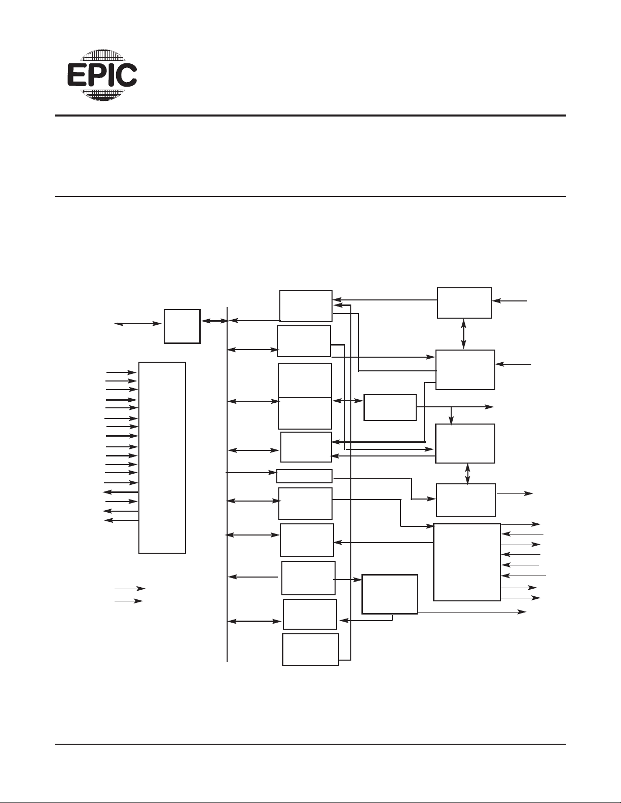
(15)
BAUDOUT
RECEIVER
BUFFER
REGISTER
LINE
CONTROL
REGISTER
DIVISOR
LATCH
(LS)
DIVISOR
LATCH
(MS
LINE
STATUS
REGISTER
FIFO
MODEM
CONTROL
REGISTER
MODEM
STATUS
REGISTER
INTERRUPT
ENABLE
REGISTER
INTERRUPT
ID
REGISTER
DATA
BUS
BUFFER
RECEIVER
SHIFT
REGISTER
RECEIVER
TIMING
&
CONTROL
TRANSMITTER
TIMING
&
CONTROL
TRANSMITTER
SHIFT
REGISTER
MODEM
CONTROL
LOGIC
BAUD
GENERATOR
INTERRUPT
CONTROL
LOGIC
SELECT
AND
CONTROL
LOGIC
D7-D0
(1-8)
(28)
(27)
(26)
(12)
(13)
(14)
(25)
(35)
(22)
(21)
(19)
(18)
(23)
(24)
(16)
(17)
(29)
A0
A1
A2
CS0
CS1
CS2•
ADR
MR
DISTR
DISTR•
DOSTR
DOSTR•
DDIS
TXRDY•
XTAL1
XTAL2
RXRDY•
POWER
(40)
3.3, 5V
SUPPLY
(20)
GND
INTRPT
(30)
(32)
RTS•
(36)
CTS•
(33)
DTR•
(37)
DSR•
(38)
DCD•
(39) RI•
(34)
OUT1•
(31)
OUT2•
SOUT
(11)
(9)
RCLK
(10)
SIN
FIFO
CONTROL
REGISTER
INTERNAL
DATA BUS
BLOCK DIAGRAM
 Loading...