

Page 1
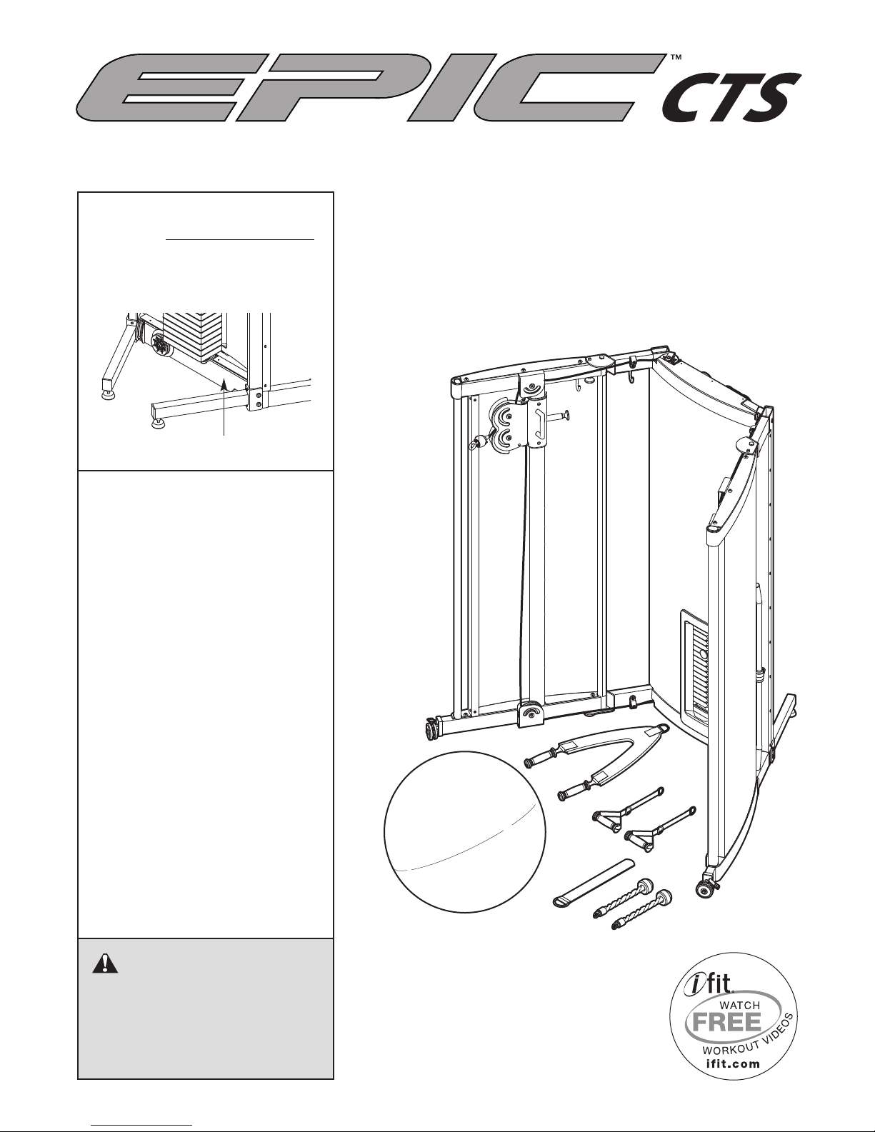
Model No. EPSY9618.0
Serial No.
Write the serial number in the
space above for future reference.
Serial Number Decal
QUESTIONS?
As a manufacturer, we are committed to providing complete customer satisfaction. If you have
questions, or if parts are missing,
DO NOT CONTACT THE STORE;
please contact Customer Care.
USERʼS MANUAL
IMPORTANT: You must note the
product model number and
serial number (see the drawing
above) before contacting us:
CALL TOLL-FREE:
1-866-362-4490
Mon.–Fri. 6 a.m.–6 p.m. MT
Sat. 8 a.m.–4 p.m. MT
ON THE WEB:
www.iconservice.com
CAUTION
Read all precautions and instructions in this manual before using
this equipment. Save this manual
for future reference.
Page 2
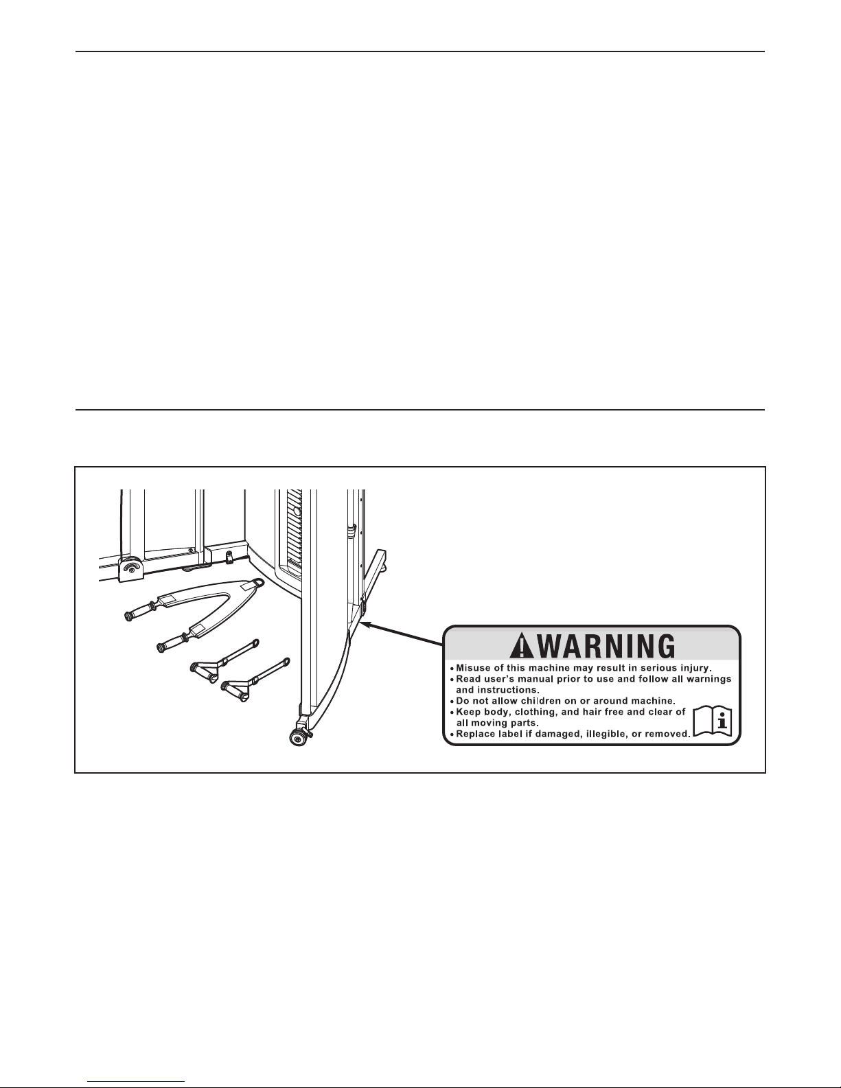
TABLE OF CONTENTS
ARNING DECAL PLACEMENT . . . . . . . . . . . . . . . . . . . . . . . . . . . . . . . . . . . . . . . . . . . . . . . . . . . . . . . . . . . . . 2
W
IMPORTANT PRECAUTIONS . . . . . . . . . . . . . . . . . . . . . . . . . . . . . . . . . . . . . . . . . . . . . . . . . . . . . . . . . . . . . . . . 3
BEFORE YOU BEGIN . . . . . . . . . . . . . . . . . . . . . . . . . . . . . . . . . . . . . . . . . . . . . . . . . . . . . . . . . . . . . . . . . . . . . . 4
ASSEMBLY . . . . . . . . . . . . . . . . . . . . . . . . . . . . . . . . . . . . . . . . . . . . . . . . . . . . . . . . . . . . . . . . . . . . . . . . . . . . . . 5
DJUSTMENT . . . . . . . . . . . . . . . . . . . . . . . . . . . . . . . . . . . . . . . . . . . . . . . . . . . . . . . . . . . . . . . . . . . . . . . . . . . . 6
A
CABLE DIAGRAM . . . . . . . . . . . . . . . . . . . . . . . . . . . . . . . . . . . . . . . . . . . . . . . . . . . . . . . . . . . . . . . . . . . . . . . . . 9
MAINTENANCE . . . . . . . . . . . . . . . . . . . . . . . . . . . . . . . . . . . . . . . . . . . . . . . . . . . . . . . . . . . . . . . . . . . . . . . . . . 10
EXERCISE GUIDELINES . . . . . . . . . . . . . . . . . . . . . . . . . . . . . . . . . . . . . . . . . . . . . . . . . . . . . . . . . . . . . . . . . . 11
PART LIST . . . . . . . . . . . . . . . . . . . . . . . . . . . . . . . . . . . . . . . . . . . . . . . . . . . . . . . . . . . . . . . . . . . . . . . . . . . . . . 13
EXPLODED DRAWING . . . . . . . . . . . . . . . . . . . . . . . . . . . . . . . . . . . . . . . . . . . . . . . . . . . . . . . . . . . . . . . . . . . . 14
ORDERING REPLACEMENT PARTS . . . . . . . . . . . . . . . . . . . . . . . . . . . . . . . . . . . . . . . . . . . . . . . . . .Back Cover
LIMITED WARRANTY . . . . . . . . . . . . . . . . . . . . . . . . . . . . . . . . . . . . . . . . . . . . . . . . . . . . . . . . . . . . . . Back Cover
WARNING DECAL PLACEMENT
This drawing shows the location(s) of the warning decal(s). If a decal is missing or illegible,
call the telephone number on the front cover
of this manual and request a free replacement decal. Apply the decal in the location
shown. Note: The decal(s) may not be shown
at actual size.
2
Page 3
IMPORTANT PRECAUTIONS
WARNING: To reduce the risk of serious injury, read all important precautions and
instructions in this manual and all warnings on the weight system before using the weight system.
ICON assumes no responsibility for personal injury or property damage sustained by or through the
se of this product.
u
1. Before beginning any exercise program,
consult your physician. This is especially
important for persons over the age of 35 or
persons with pre-existing health problems.
2. It is the responsibility of the owner to ensure
that all users of the weight system are adequately informed of all precautions.
3. The weight system is intended for home use
only. Do not use the weight system in a commercial, rental, or institutional setting.
4. Use the weight system only on a level surface. Cover the floor beneath the weight system to protect the floor.
5. Inspect and properly tighten all parts regularly. Replace any worn parts immediately.
6. Keep children under age 12 and pets away
from the weight system at all times.
7. Wear appropriate exercise clothes while
exercising; do not wear loose clothes that
could become caught on the weight system.
Always wear athletic shoes for foot protection while exercising.
are exercising, stop immediately and make
sure that the cables are on the pulleys.
11. Make sure that the wheels, frame feet, and
leveling feet are all level with the floor (see
LEVELING THE WEIGHT SYSTEM on page
6).
12. Never release the handles, triceps ropes,
ankle strap, ab strap, or lat bar while weights
are raised; the weights will fall with great
force.
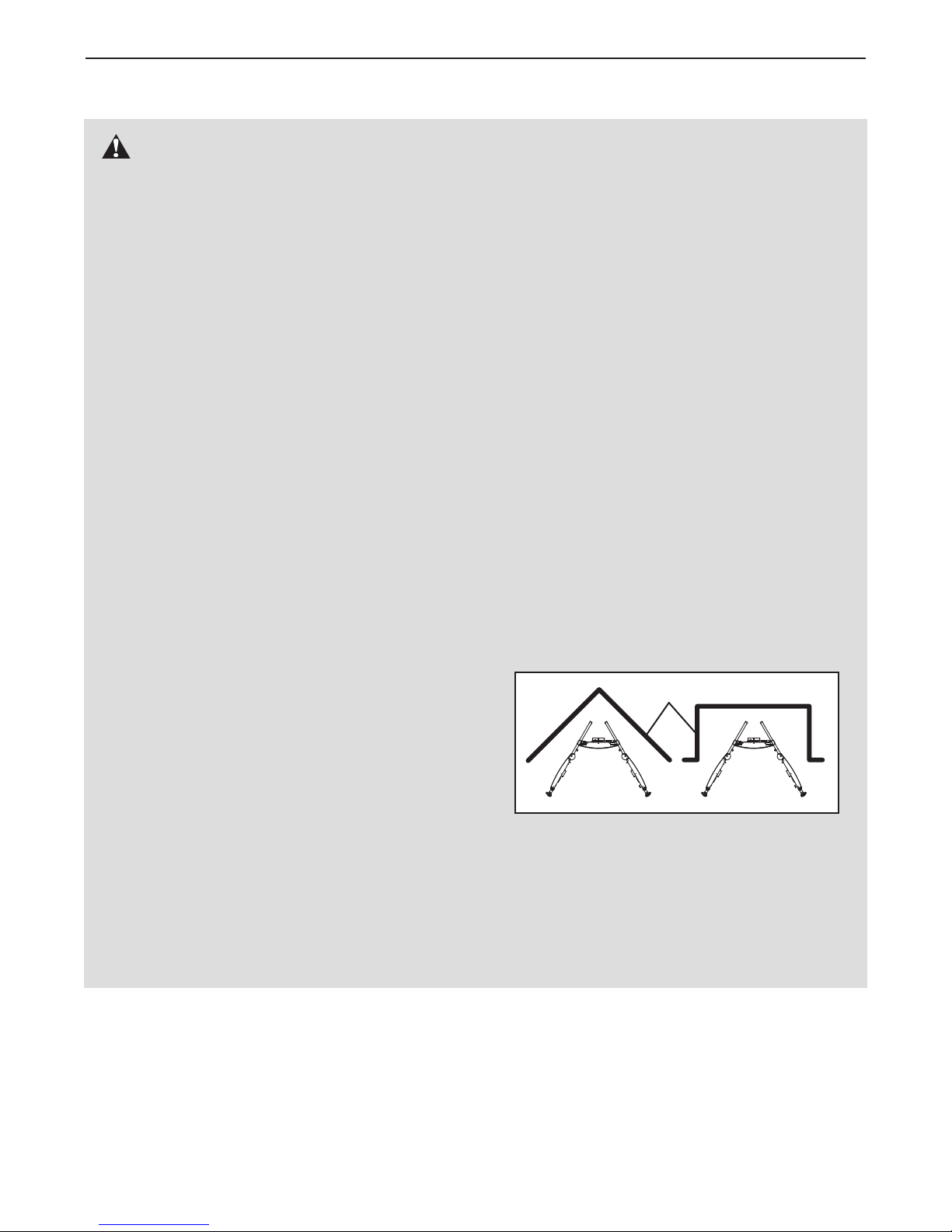
13. This weight system has an open weight
stack; the weight stack must not be accessible from any point outside of the userʼs field
of view. To prevent access to the weight
stack, place the weight system in a corner or
bay of a room, as shown in the drawing
below. There must be no more than 3 ft. (1 m)
of clearance between the weight system and
the adjacent walls.
Wall
8. Keep hands and feet away from moving
parts.
9. Always secure the weight stack with the lock
pin and lock after exercising to prevent
unauthorized use of the weight system (see
LOCKING THE WEIGHT STACK on page 6).
10. Make sure that the cables remain on the pulleys at all times. If the cables bind while you
14. If you feel pain or dizziness while exercising,
stop immediately and begin cooling down.
15. Use the weight system only as described in
this manual.
3
Page 4
BEFORE YOU BEGIN
hank you for selecting the versatile EPIC
T
system. The weight system offers a selection of weight
stations designed to develop every major muscle group
of the body. Whether your goal is to tone your body,
uild dramatic muscle size and strength, or improve
b
your cardiovascular system, the weight system will help
you to achieve the specific results you want.
For your benefit, read this manual carefully before
you use the vibration platform. If you have ques-
tions after reading this manual, please see the front
cover of this manual. To help us assist you, note the
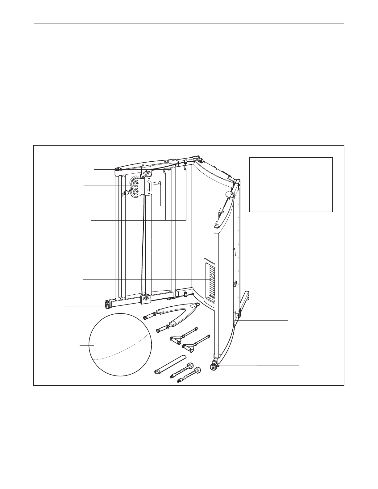
Adjustment Knob
Pulley Station
Pulley Knob
Accessory Hook
®
TS weight
C
roduct model number and serial number before con-
p
tacting us. The model number and the location of the
serial number decal are shown on the front cover of
this manual.
To avoid a registration fee for any service needed
under warranty, you must register the weight system at www.iconservice.com/registration.
Before reading further, please familiarize yourself with
the parts that are labeled in the drawing below.
ASSEMBLED
DIMENSIONS:
Height: 6 ft. 6 in. (197 cm)
Width: 6 ft. 2 in. (187 cm)
Depth: 4 ft. 5 in. (134 cm)
Weight: 350 lbs. (159 kg)
Right Side
Weight Stack
Wheel
Accessories
Left Side
Weight Pin
Leveling Foot
Accessory Rest
Wheel Lock
4
Page 5
ASSEMBLY
. Note: Assembly requires two persons. For
1
clarity, some parts are not shown.
Place all parts in a cleared area and remove the
acking materials; do not dispose of the pack-
p
ing materials until assembly is completed.
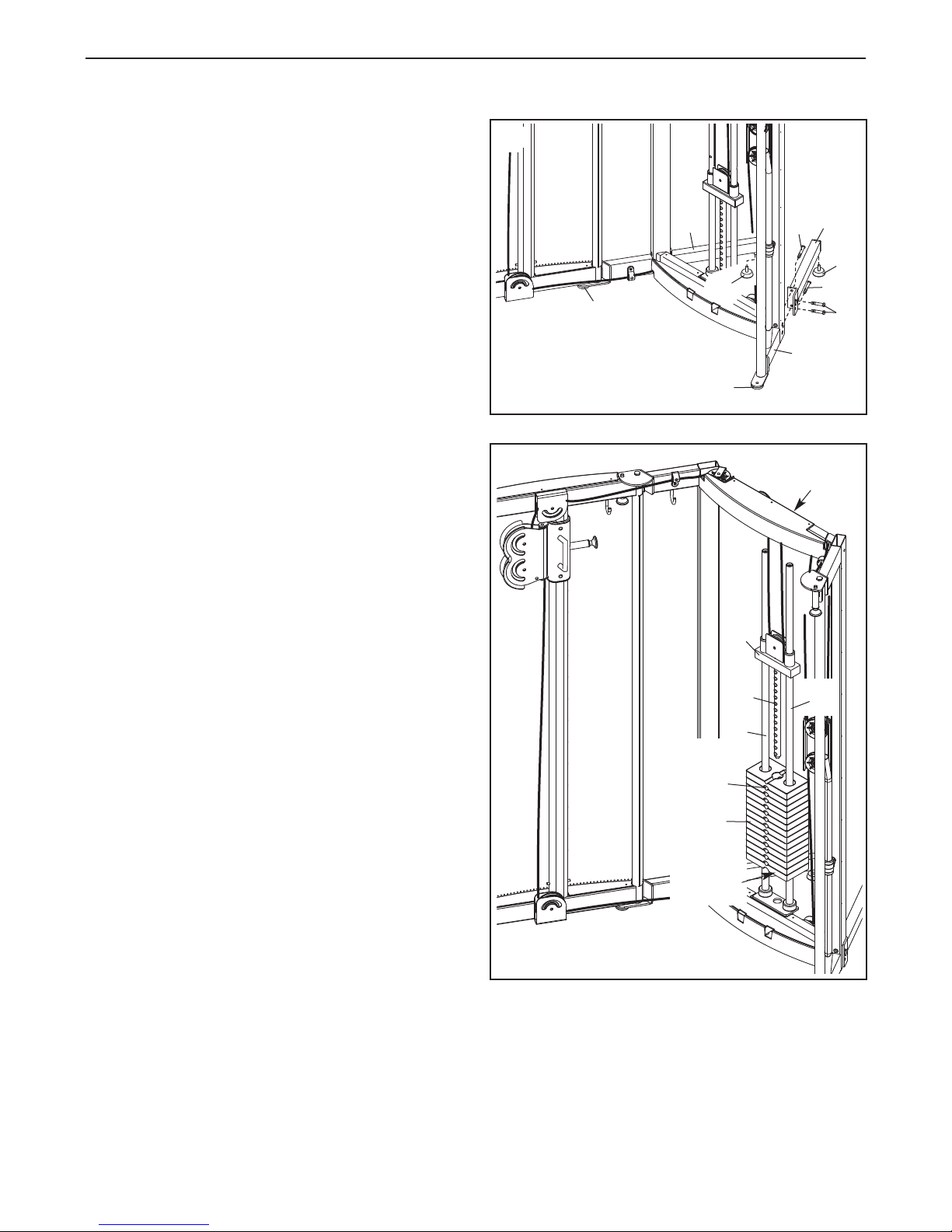
1
8
73
9
Attach the Left Rear Frame (9) to the Center
Frame (1) with four M10 x 25mm Screws (73).
Next, tighten a Leveling Foot (44) into the Left
Rear Frame. Attach the Right Rear Frame (8)
and the other Leveling Foot (44) in the same
way. Make sure that the Leveling Feet, the
Frame Feet (45), and the Wheels (not shown)
are all level with the floor (see page 6).
2. Loosen the two Weight Guides (22) from the top
of the Center Frame (1). Then, remove the
Header Plate (23) from the Weight Guides.
Next, locate the Weight (25) with the highest
number decal. Orient the Weight so that the number decal is right-side-up. Then, slide the Weight
onto the Weight Guides (22). Slide the remain-
ing Weights (25) onto the Weight Guides in
the same way.
Slide the Header Plate (23) onto the Weight
Guides (22). Next, insert the Weight Selector (26)
into the Weights (25). Then, tighten the Weight
Guides into the top of the Center Frame (1).
44
44
45
45
2
23
26
22
73
73
1
1
22
Pin
Hole
25
Number
Decal
3. Make sure that all parts are properly tightened. The use of the remaining parts will be explained in ADJUSTMENT, beginning on page 6.
Before using the weight system, pull each cable a few times to make sure that the cables move smoothly
around the pulleys. If one of the cables does not move smoothly, find and correct the problem. IMPORTANT:
If the cables are not properly installed, they may be damaged when heavy weight is used. See the
CABLE DIAGRAM on page 9 for proper cable routing. If there is any slack in the cables, you will
need to remove the slack by tightening the cables. See MAINTENANCE on page 10.
5
Page 6

ADJUSTMENT
his section explains how to adjust the weight system. See the EXERCISE GUIDELINES on page 11 for impor-
T
tant information about how to get the most benefit from your exercise program. Also, refer to the accompanying
exercise guide to see the correct form for several exercises.
LEVELING THE WEIGHT SYSTEM
To level the weight system, turn the Leveling Foot
(44) in the Left Rear Frame (9) or the Right Rear
Frame (not shown) until the weight system is level
with the floor. Make sure that the Leveling Feet, the
Frame Feet (45), and the Left and Right Wheels
(47, 79) are all level with the floor.
LOCKING THE WEIGHT STACK
45
79
47
44
9
44
45
Note: For clarity, the left side of the weight system and the center shroud are not shown.
To lock the weight stack, insert the Lock Pin (52)
through a Weight Guide (22), and secure the Lock
(53) on the Lock Pin.
CHANGING THE WEIGHT SETTING
To change the setting of the weight stack, insert the
Weight Pin (27) under the desired Weight (25).
Note: Each Weight (25) contains two number
decals. The larger number represents the amount
of resistance when you use both; the smaller
number represents the amount of resistance
when you use a single pulley station.
27
25
22
53
52
6
Page 7

ATTACHING THE ACCESSORIES TO A PULLEY
STATION
ttach the Lat Bar (31) to either Cable Stop (37) with a
A
Cable Clip (65). The two Handles (32), the two
riceps Ropes (33), the Ab Strap (34), or the Ankle
T
Strap (35) can be attached at either pulley station
in the same way.
34
31
65
7
3
32
STORING THE ACCESSORIES
You can store the Lat Bar (31) in the indicated hole in
the base of the Center Frame (1).
You can store the two Handles (32) and the Ab Strap
(34) on the hooks on the Center Frame (1).
You can store the two Triceps Ropes (33) and the
Ankle Strap (35) on the hooks on the Right and Left
Top Frames (6, 7).
35
33
6
Hook
33
1
Hooks
Hook
7
31
34
32
35
33
1
Hole
7
Page 8

ADJUSTING THE PULLEY CARRIAGES
To adjust the height of the right Pulley Carriage (20),
pull the indicated Adjustment Knob (29), slide the
ight Pulley Carriage to the desired height, and then
r
engage the Adjustment Knob in one of the adjustment
holes in the Right Pulley Carriage Guide (90). Make
sure that the Adjustment Knob is fully engaged in
ne of the holes in the Right Pulley Carriage
o
Guide.
Adjust the left Pulley Carriage (not shown) in the
same way.
CLOSING AND OPENING THE WEIGHT SYSTEM
To close the weight system, first remove all accessories from the Cable Stops (37). Store the accessories if desired (see STORING THE ACCESSORIES
on page 7). Then, adjust the Pulley Carriages (20) to
the highest position (see ADJUSTING THE PULLEY
CARRIAGES above).
Next, unlock the Right Wheel (79) by lifting upward on
the right wheel lock. Then, locate the words 1st FOLD
on the Right Top Frame (6). Pull the Adjustment Knob
(29) that is below the words 1st FOLD. Rotate the
Right Frame (2) towards the Center Shroud (17).
Lock the Right Wheel by pressing downward on the
right wheel lock.
37
1st Fold
20
9
29
0
6
20
29
29
7
2nd Fold
36
17
Unlock the Left Wheel (47) by lifting upward on the
left wheel lock. Next, locate the words 2nd FOLD on
the Left Top Frame (7). Pull the Adjustment Knob (29)
that is below the words 2nd FOLD. Then, rotate the
Left Frame (3) towards the Center Shroud (17) until
the Magnets (36) engage the Right Frame (2). Lock
the Left Wheel by pressing downward on the left
wheel lock.
To open the weight system, lift upward on the left
wheel lock to unlock the Left Wheel (47). Rotate the
Left Frame (3) away from the Center Shroud (17) until
the Adjustment Knob (29) engages the hole in the
Left Top Frame (7). Press downward on the left wheel
lock to lock the Left Wheel. Open the Right Frame
(2) in the same way.
Wheel
Lock
2
79
36
3
47
Wheel
Lock
8
Page 9

CABLE DIAGRAM
The diagram below shows the proper routing of the cables. The numbers in each drawing show the proper route
of that cable. Use the diagram to make sure that the cables, cable traps, pulleys, and guards are assembled
orrectly. If the cables are not assembled correctly, the weight system will not function properly and damage may
c
occur. Make sure that the cable traps do not touch or bind the cables.
3
4
5
2
1
High Cable (38)
Length: 27 ft. 11 in. (9 m)
1
11
6
7
8
10
9
12
13
Low Cable (74)
Length: 17 ft. 7 in. (5 m)
8
5
3
4
2
6
7
9
Page 10

MAINTENANCE
Make sure that all parts are properly tightened each time the weight system is used. Replace any worn parts
immediately. The weight system can be cleaned with a damp cloth and a mild, non-abrasive detergent; do not
use solvents to clean the weight system.
TIGHTENING THE CABLES
Woven cable, the type of cable used on the weight system, can stretch slightly when it is first used. If there is
slack in the cables before resistance is felt, the cables should be tightened. To tighten the cables, first insert the
weight pin into the middle of the weight stack. Slack can be removed from these cables several ways:
Remove the M10 Locknut (70) and the M10 x 40mm
Bolt (71) from the Small Pulley (40) near the lower
end of the Pulley Plate (41). Reattach the Small
Pulley and the Cable Trap to the hole closer to the
center of the Pulley Plate. Make sure that the Low
Cable (74) and the Small Pulley move smoothly.
70
If necessary, adjust the position of the Small Pulley
(40) near the upper end of the Pulley Plate (41) in the
same way.
40
40
41
71
Do not overtighten the cables. If the cables are overtightened, the top weight will be lifted off the weight
stack. If a cable tends to slip off the pulleys often, it may have become twisted. Remove the cable and
reinstall it. If the cables need to be replaced, see ORDERING REPLACEMENT PARTS on the back cover of
this manual.
74
10
Page 11

EXERCISE GUIDELINES
THE FOUR BASIC TYPES OF WORKOUTS
Muscle Building
To increase the size and strength of your muscles,
push them close to their maximum capacity. Your muscles will continually adapt and grow as you progressively increase the intensity of your exercise. You can
adjust the intensity level of an individual exercise in
two ways:
• by changing the amount of resistance used
• by changing the number of repetitions or sets per-
formed. (A “repetition” is one complete cycle of an
exercise, such as one sit-up. A “set” is a series of
repetitions.)
The proper amount of resistance for each exercise
depends upon the individual user. You must gauge
your limits and select the amount of resistance that is
right for you. Begin with 3 sets of 8 repetitions for each
exercise you perform. Rest for 3 minutes after each
set. When you can complete 3 sets of 12 repetitions
without difficulty, increase the amount of resistance.
Toning
You can tone your muscles by pushing them to a moderate percentage of their capacity. Select a moderate
amount of resistance and increase the number of repetitions in each set. Complete as many sets of 15 to
20 repetitions as possible without discomfort. Rest for
1 minute after each set. Work your muscles by completing more sets rather than by using high amounts of
resistance.
The combination of strength training and aerobic exer-
ise will reshape and strengthen your body, plus devel-
c
op your heart and lungs.
PERSONALIZING YOUR EXERCISE PROGRAM
Determining the appropriate length of time for each
workout, and the numbers of repetitions and sets to
complete, is an individual matter. Avoid overdoing it
during the first few months of your exercise program.
Progress at your own pace and be sensitive to your
bodyʼs signals. If you experience pain or dizziness
while exercising, stop immediately and cool down.
Find out what is wrong before continuing. Remember
that adequate rest and a proper diet are important factors in any exercise program.
WARMING UP
Begin each workout with 5 to 10 minutes of stretching
and light exercise to warm up. Warming up prepares
your body for more strenuous exercise by increasing
circulation, raising your body temperature, and delivering more oxygen to your muscles.
WORKING OUT
Each workout should include 6 to 10 different exercises. Select exercises for every major muscle group,
emphasizing areas that you want to develop most. To
give balance and variety to your workouts, vary the
exercises from workout to workout.
Weight Loss
To lose weight, use a low amount of resistance and
increase the number of repetitions in each set.
Exercise for 20 to 30 minutes, resting for a maximum
of 30 seconds between sets.
Cross Training
Cross training is an efficient way to get a complete and
well-balanced fitness program. An example of a balanced program follows:
• Plan strength training workouts on Monday,
Wednesday, and Friday.
• Plan 20 to 30 minutes of aerobic exercise, such as
running on a treadmill or riding on an elliptical exerciser or exercise cycle, on Tuesday and Thursday.
• Rest from both strength training and aerobic exercise
for at least one full day each week to give your body
time to regenerate.
Schedule your workouts for the time of day when your
energy level is the highest. Each workout should be
followed by at least one day of rest. Once you find the
schedule that is right for you, stick with it.
EXERCISE FORM
Maintaining proper form is an essential part of an
effective exercise program. This requires moving
through the full range of motion for each exercise, and
moving only the appropriate parts of the body.
Exercising in an uncontrolled way will leave you feeling exhausted. On the exercise guide accompanying
this manual you will find photographs showing the correct form for several exercises, and a list of the muscles affected. See the muscle chart on the next page
to find the names of the muscles.
11
Page 12

O
P
Q
R
S
T
U
V
X
W
N
M
J
G
F
H
I
K
E
C
D
B
A
L
MUSCLE CHART
A. Sternomastoid (neck)
B. Pectoralis Major (chest)
C. Biceps (front of arm)
D. Obliques (waist)
E. Brachioradials (forearm)
F. Hip Flexors (upper thigh)
G. Abductor (outer thigh)
H. Quadriceps (front of thigh)
I. Sartorius (front of thigh)
J. Tibialis Anterior (front of calf)
K. Soleus (front of calf)
L. Anterior Deltoid (shoulder)
M. Rectus Abdominus (stomach)
N. Adductor (inner thigh)
O. Trapezius (upper back)
P. Rhomboideus (upper back)
Q. Posterior Deltoid (shoulder)
R. Triceps (back of arm)
S. Latissimus Dorsi (mid back)
T. Spinae Erectors (lower back)
U. Gluteus Medius (hip)
V. Gluteus Maximus (buttocks)
W. Hamstring (back of leg)
X. Gastrocnemius (back of calf)
The repetitions in each set should be performed
smoothly and without pausing. The exertion stroke of
each repetition should last about half as long as the
eturn stroke. Proper breathing is important. Exhale
r
during the exertion stroke of each repetition and
nhale during the return stroke. Never hold your
i
breath.
Rest for a short period of time after each set. The
ideal resting periods are:
• Rest for three minutes after each set for a muscle
building workout.
• Rest for one minute after each set for a toning work-
out.
• Rest for 30 seconds after each set for a weight loss
workout.
Plan to spend the first couple of weeks familiarizing
yourself with the equipment and learning the proper
form for each exercise.
COOLING DOWN
End each workout with 5 to 10 minutes of stretching.
nclude stretches for both your arms and legs. Move
I
slowly as you stretch and do not bounce. Ease into
ach stretch gradually and go only as far as you can
e
without strain. Stretching at the end of each workout
is an effective way to increase flexibility.
STAYING MOTIVATED
For motivation, keep a record of each workout. Write
the date, the exercises performed, the resistance
used, and the numbers of sets and repetitions completed. Record your weight and key body measurements at the end of every month. The key to achieving
the greatest results is to make exercise a regular and
enjoyable part of your everyday life.
12
Page 13

PART LIST—Model No. EPSY9618.0 R1108A
Key No. Qty. Description Key No. Qty. Description
11Center Frame
21Right Frame
31Left Frame
4
51Left Pulley Carriage Guide
61Right Top Frame
71Left Top Frame
81Right Rear Frame
91Left Rear Frame
10 1 Center Upper Shroud
11 1 Right Upper Shroud
12 1 Left Upper Shroud
13 1 Right Lower Shroud
14 1 Left Lower Shroud
15 1 Left Shroud
16 1 Right Shroud
17 1 Center Shroud
18 1 Trim
19 1 Center Lower Shroud
20 2 Pulley Carriage
21 1 Left Swivel Bracket
22 2 Weight Guide
23 1 Header Plate
24 2 Header Plate Bushing
25 14 Weight
26 1 Weight Selector
27 1 Weight Pin
28 2 Weight Bumper
29 4 Adjustment Knob
30 1 Pulley Guard
31 1 Lat Bar
32 2 Handle
33 2 Triceps Rope
34 1 Ab Strap
35 1 Ankle Strap
36 2 Magnet Box
37 2 Cable Stop
38 1 High Cable
39 8 Large Pulley
40 11 Small Pulley
41 1 Pulley Plate
42 4 Cable Clip
43 6 Cable Trap
44 2 Leveling Foot
45 2 Frame Foot
46 1 Left Frame Cap
47 1 Left Wheel
48 1 Left Large Bracket Bushing
49 1 Left Spring
50 2 Small Bracket Bushing
2 Upright
51 4 Carriage Bushing
52 1 Lock Pin
53 1 Lock
4 4 M10 x 20mm Shoulder Bolt
5
55 4 Bushing
56 24 M10 Washer
57 2 M10 x 265mm Bolt
58 1 Right Frame Cap
59 60 M4 x 19mm Self-tapping Screw
60 4 M10 x 85mm Bolt
61 2 M4 Nut
62 4 M10 x 60mm Bolt
63 2 M4 x 12mm Screw
64 9 M10 x 45mm Bolt
65 2 Cable Clip
66 4 M4 Washer
67 8 M4 x 16mm Screw
68 6 M10 x 80mm Bolt
69 2 M4 x 10mm Screw
70 19 M10 Locknut
71 3 M10 x 40mm Bolt
72 4 M4 x 50mm Screw
73 16 M10 x 25mm Screw
74 1 Low Cable
75 2 38mm x 50mm Inner Cap
76 2 25mm Round Cap
77 2 38mm x 76mm Inner Cap
78 2 30mm x 48mm Inner Cap
79 1 Right Wheel
80 1 Round Frame Bumper
81 2 Bolt Bumper
82 2 M8 Locknut
83 8 M6 x 10mm Screw
84 8 M6 Locknut
85 2 M4 x 4.5mm Screw
86 1 Exercise Ball
87 2 M10 x 95mm Screw
88 1 Right Large Bracket Bushing
89 1 Right Spring
90 1 Right Pulley Carriage Guide
91 1 Right Swivel Bracket
92 28 Weight Bushing
93 4 Magnet
94 2 Magnet Spacer
95 2 Magnet Cover
*—Hand Pump
*–Userʼs Manual
*–Exercise Guide
*—DVD
Note: Specifications are subject to change without notice. See the back cover of this manual for information
about ordering replacement parts. *These parts are not illustrated.
13
Page 14

1
31
8
9
10
35
3
4
33
32
17
18
27
28
25
26
23
24
40
64
70
53
52
40
64
43
41
71
40
40
70
19
67
54
42
40
64
44
68
30
40
67
42
45
54
40
44
68
70
73
73
73
73
73
73
59
59
59
55
68
40
70
67
42
68
68
40
67
42
54
22
59
59
59
59
59
59
59
59
59
59
40
43
43
77
55
77
56
54
66
56
76
76
63
56
55
43
66
61
71
75
75
45
63
61
55
56
56
69
66
65
43
86
92
92
EXPLODED DRAWING A—Model No. EPSY9618.0 R1108A
14
Page 15

39
38
37
91
50
70
51
70
29
51
20
88
89
57
90
38
37
39
50
70
64
64
21
48
49
57
70
51
20
29
51
5
47
82
46
3
2
60
73
73
70
14
59
59
4
62
62
60
79
58
82
13
59
59
62
29
60
39
1
1
6
59
59
83
83
59
59
16
83
83
15
62
12
7
59
59
39
29
72
36
60
70
64
64
39
59
59
59
59
59
59
59
59
59
78
7
8
73
73
70
5
6
56
56
56
73
73
70
56
56
56
39
56
56
56
81
81
70
59
73
73
70
56
56
80
74
74
84
84
84
84
84
85
85
93
87
56
87
56
4
94
93
93
95
36
93
94
95
72
EXPLODED DRAWING B—Model No. EPSY9618.0 R1108A
15
Page 16

ORDERING REPLACEMENT PARTS
To order replacement parts, please see the front cover of this manual. To help us assist you, be prepared to
provide the following information when contacting us:
• the model number and serial number of the product (see the front cover of this manual)
• the name of the product (see the front cover of this manual)
• the key number and description of the replacement part(s) (see the PART LIST and the EXPLODED
DRAWING near the end of this manual)
LIMITED WARRANTY
ICON Health & Fitness, Inc. (ICON) warrants this product to be free from defects in workmanship and
material, under normal use and service conditions. The frame is warranted for a lifetime. Parts and
labor are warranted for one (1) year from the date of purchase.
This warranty extends only to the original purchaser. ICONʼs obligation under this warranty is limited to
repairing or replacing, at ICONʼs option, the product through one of its authorized service centers. All
repairs for which warranty claims are made must be preauthorized by ICON. If the product is shipped to
a service center, freight charges to and from the service center will be the customerʼs responsibility. For
replacement parts shipped while the product is under warranty, the customer will be responsible for a
minimal handling charge. For in-home service, the customer will be responsible for a minimal trip
charge. This warranty does not extend to any damage to a product caused by or attributable to freight
damage, abuse, misuse, improper or abnormal usage, or repairs not provided by an ICON authorized
service center; products used for commercial or rental purposes; or products used as store display
models. No other warranty beyond that specifically set forth above is authorized by ICON.
ICON is not responsible or liable for indirect, special, or consequential damages arising out of or in connection with the use or performance of the product; damages with respect to any economic loss, loss of
property, loss of revenues or profits, loss of enjoyment or use, or costs of removal or installation; or
other consequential damages of whatsoever nature. Some states do not allow the exclusion or limitation of incidental or consequential damages. Accordingly, the above limitation may not apply to you.
The warranty extended hereunder is in lieu of any and all other warranties, and any implied warranties
of merchantability or fitness for a particular purpose are limited in their scope and duration to the terms
set forth herein. Some states do not allow limitations on how long an implied warranty lasts.
Accordingly, the above limitation may not apply to you.
This warranty gives you specific legal rights. You may also have other rights that vary from state to state.
ICON Health & Fitness, Inc., 1500 S. 1000 W., Logan, UT 84321-9813
Part No. 272318 R1108A Printed in China © 2008 ICON IP, Inc.
 Loading...