

Page 1
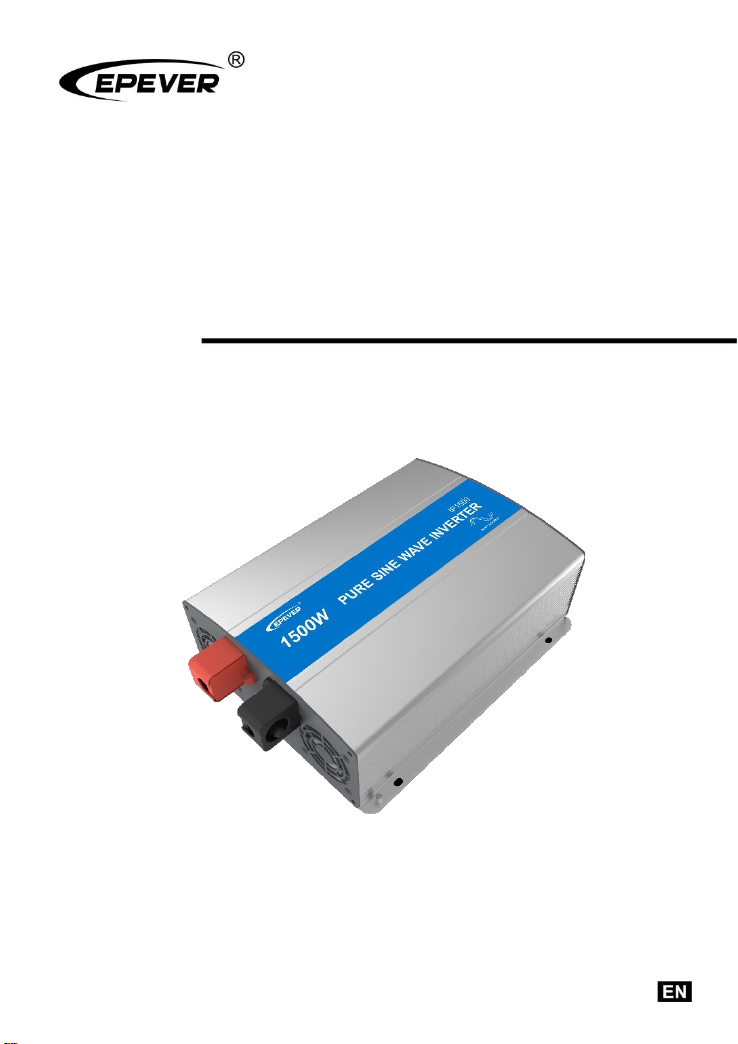
Pure Sine Wave Inverter
User Manual
IP350-12/22/11/21
IP500-12/22/11/21
IP1000-12/22/11/21
IP1500-12/22/11/21
IP2000-22/42/21/41
Page 2

Page 3

CONTENTS
1. Important Safety Instructions ............................................... 1
2. Introduction ........................................................................... 3
3. Designations of models ........................................................ 4
4. Wiring ................................................................................... 5
5. Functions .............................................................................. 7
6. Protection ............................................................................. 11
7. Troubleshooting .................................................................... 13
8. Maintenance ......................................................................... 14
9. Disclaimer ............................................................................. 15
10. Technical Specification ....................................................... 16
Page 4

1
1. Important Safety Instructions
As an AC power supply equipment, the inverter's AC output is the same as the household
power plug's. The inverter's AC output should be treated with caution; otherwise, there will
be a risk of electric shock! When using, please note the following:
Attentions:
Connect the DC input according to the requirement strictly. The IPower inverter has a
relatively wide DC input range. Still, too high or too low DC input may cause problems
even destroy the inverter.
A reverse polarity connection will blow the fuses in the inverter and damage the unit.
Do not expose the inverter to a humid, flammable, explosive, or dust environment.
Keep the inverter out of children's touch.
It is recommended to connect the inverter input terminal to the battery. Calculate the
minimum capacity of the battery(expressed in AH) in the following way: 5times of the
rated power of the inverter/battery voltage. If for testing purposes, the user should
select DC power supply current at least twice greater than that of the inverter rated
input to keep normal inverter operation. Using a DC power supply for testing may
cause damage to the inverter.
When the inverter works continuously, its surface may become very hot; please ensure
the air ventilation clearance around the inverter is more than 10cm. Keep away from
the material or device which may suffer from high temperature when the inverter is
working. Do not install the inverter in an airproof location and keep enough space
around the inverter.
Connect the protective grounding to the ground. The cross-section of the wire should
not be less than 4mm2.
The wire connection between the battery and the inverter should be less than 3m, and
the current density should be less than 3.5A/mm2. At this time, the inverter is running at
full load. If the wire length exceeds 3m, please reduce the current density.
A fuse or breaker should be used between the battery and the inverter. The value of
the fuse or breaker should be twice the inverter's rated input current.
Do not connect the battery charger or similar devices to the inverter's input terminal.
Do not put the inverter close to the flooded lead-acid battery because the terminals'
sparkle may ignite the hydrogen released by the battery.
Page 5

2
It's an off-grid inverter. Do not connect the AC output terminals to the grid or electrical
source; otherwise, the inverter may be damaged.
This inverter can only be used singly in parallel connections. The series connection will
damage the inverters.
Risk of electric shock, don't touch the output port when the inverter is working. The
output is forbidden to connect to other power sources or grids; otherwise, the inverter
will be damaged. The inverter must be turned off when connecting the load.
Please do not attempt to repair the fault inverter by yourself; otherwise, it may lead to a
severe accident. Don't hesitate to get in touch with the manufacture's engineer.
IPower series is only suitable for civil applications, not for industrial applications.
Page 6

3
2. Introduction
IPower series is a pure sine wave inverter that can convert 12/24/48VDC to 220/230VAC(or
110/120VAC). Industrial design has a wide operating temperature, high reliability, and high
efficiency compared with civil design. Simple appearance and lightweight make it easy to
install and operate. The wide input voltage range is ideal for solar system applications. This
inverter is especially suitable for civil applications, such as household emergency lighting
systems, vehicle-mounted systems, small field power supply, etc.
Features:
Safe design with input and output electrical isolation
Adoption of advanced SPWM technology, pure sine wave output
Optional output voltage 220/230VAC(or 110/120VAC), chosen by DIP switch
LED indicators for fault status and working status
Lower No-load consumption
Max. efficiency up to 95%(IP2000-22, IP2000-42)①
Input protection: Over voltage protection, low voltage protection
Output protection: Overload protection, short circuit protection
Over-temperature protection: Temperature-controlled Fan Ventilation; Inverter turns off
automatically when overheating
Operational USB output 5VDC/1A
Operational RS485 communication port②
① The efficiency is tested at rated input voltage,220V output with resistive load, 25℃
Ambient temperature,1500W and higher version
② 1000W and higher version support RS485 communication port optional.
Page 7
4
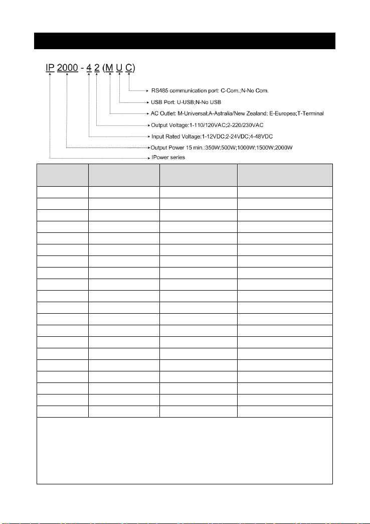
3. Designations of models
Model
Input Rated
Voltage
Output Voltage
Output Power
15 min.
IP350-12
12VDC
220/230VAC
350W
IP350-22
24VDC
220/230VAC
350W
IP500-12
12VDC
220/230VAC
500W
IP500-22
24VDC
220/230VAC
500W
IP1000-12
12VDC
220/230VAC
1000W
IP1000-22
24VDC
220/230VAC
1000W
IP1500-12
12VDC
220/230VAC
1500W
IP1500-22
24VDC
220/230VAC
1500W
IP2000-22
24VDC
220/230VAC
2000W
IP2000-42
48VDC
220/230VAC
2000W
IP350-11
12VDC
110/120VAC
350W
IP350-21
24VDC
110/120VAC
350W
IP500-11
12VDC
110/120VAC
500W
IP500-21
24VDC
110/120VAC
500W
IP1000-11
12VDC
110/120VAC
1000W
IP1000-21
24VDC
110/120VAC
1000W
IP1500-11
12VDC
110/120VAC
1500W
IP1500-21
24VDC
110/120VAC
1500W
IP2000-21
24VDC
110/120VAC
2000W
IP2000-41
48VDC
110/120VAC
2000W
220/230VAC output outlet: Universal, Australia/New Zealand, European,
Terminal(IP1000 and above models).
110/120VAC output outlet: Universal, Terminal(IP1000 and above models).
All the IPower models have an option for USB output.
All the IPower models have an option for RS485 communication except
IP350 and IP500.
Page 8
5
4. Wiring
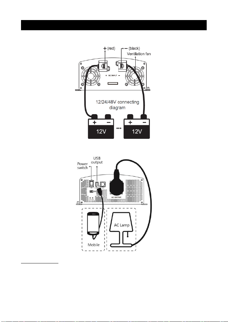
(1)12/24/48Vsystem DC input
(2) 220/230V AC(or 110/120V) output
Operation Steps:
Step 1: Turn the power switch of the inverter to OFF
Step 2: Disconnect the input breaker or the fuse between the inverter and battery. Connect
the battery terminals ('+' with the red line and '-' with the black line). Do not connect
the poles by contraries.
Page 9

6
Step 3: Use the cable no less than 4mm2 to connect the inverter's grounding terminal to the
ground.
Step 4: Connect the plug of AC load to the inverter AC outlet
Step 5: Switch on the input breaker or the fuse between the inverter and battery; turn on
the power switch to start the inverter. If the green indicator is ON, turn on the loads
one by one. Check the operation state of the inverter and loads.
Step 6: If there are different loads, the loads with higher startup current should be turned on
first, such as television. After the loads work stably, turn on the loads with a lower
startup current, such as an incandescent lamp.
Step 7: If the Fault indicator is red and the buzzer alarms when turning on the devices,
please immediately switch off the loads and inverter.
Note: When using a USB port for charging, charge the power bank first and
then use the power bank to charge mobile phones.
Page 10
7
5. Functions
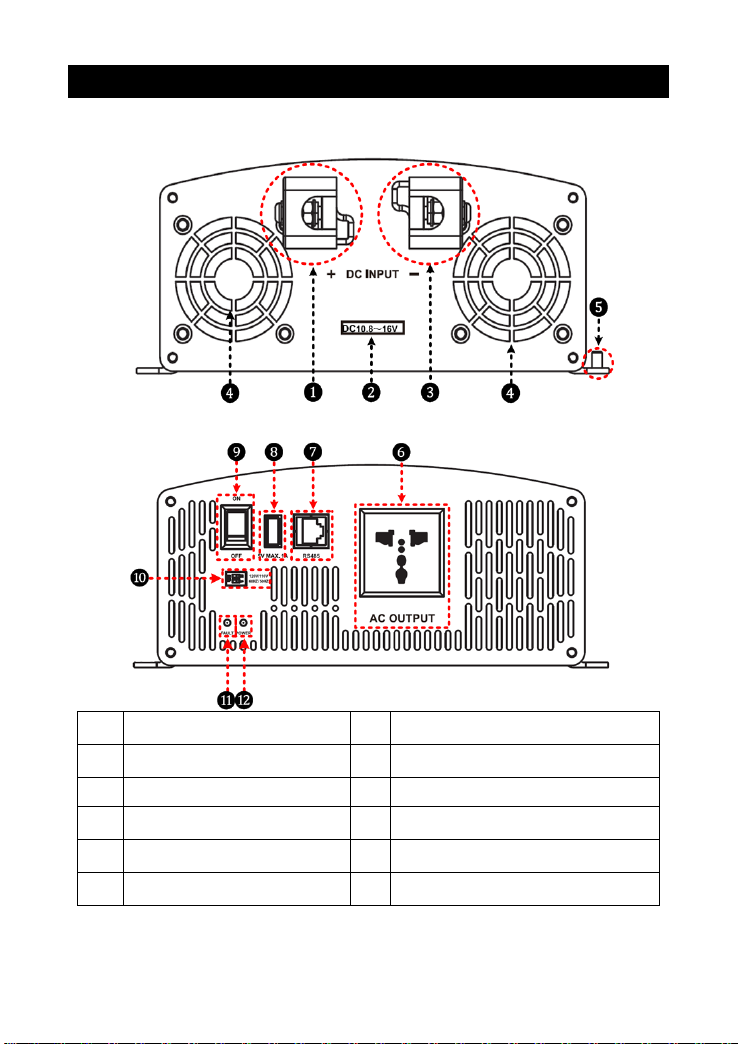
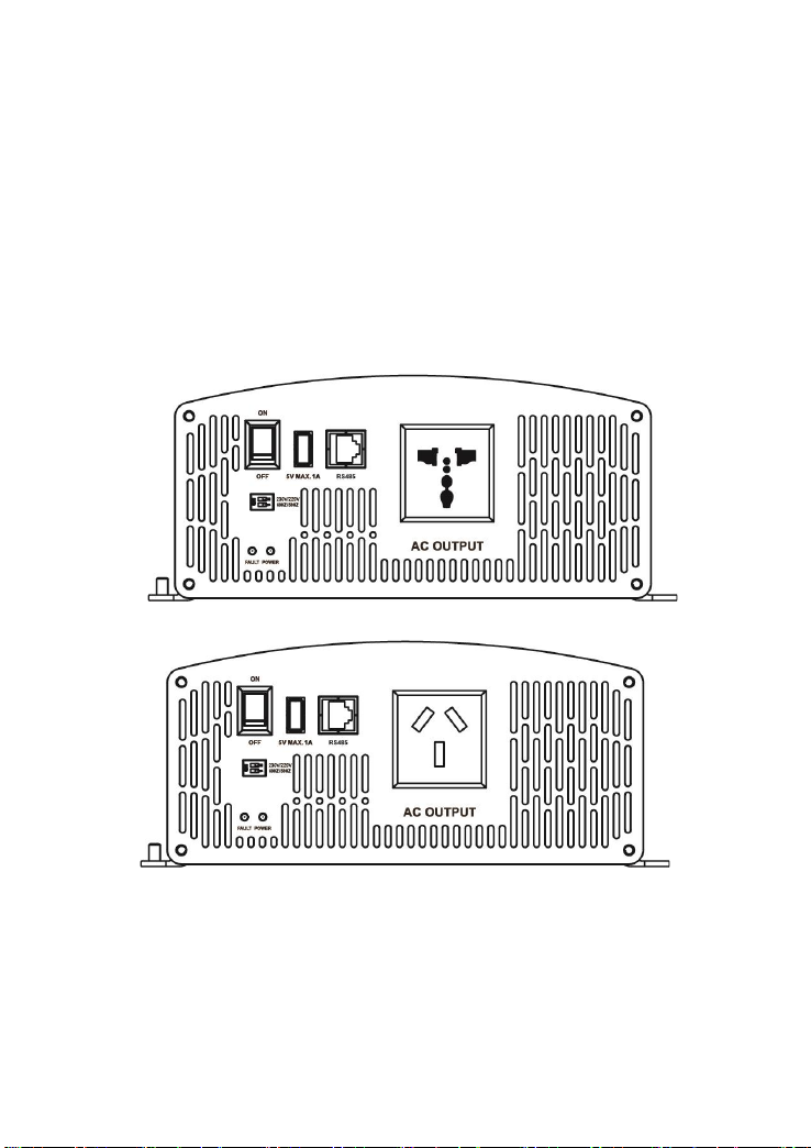
DC Input Panel
AC Output Panel
❶
DC Input Terminal Positive
❼
RS485 communication port
(4)
❷
DC input voltage range
(1)
❽
USB output port (5VDC/1A)
❸
DC Input Terminal Negative
❾
AC output switch
❹
Ventilation Fan
(2)
❿
Mode switch
(5)
❺
Grounding Terminal
⓫
Fault indicator(red)
(6)
❻
AC Outlet
(3)
⓬
Working indicator(green)
(6)
(1) Input rated voltage
12V system input voltage range is 10.8~16V;
Page 11
8
24V system input voltage range is 21.6~32V;
48V system input voltage range is 43.2~60V。
(2) Fan Ventilation
When the heat sink temperature is higher than 50℃ or the internal temperature is
higher than 50℃, the fan will turn on automatically.
When the heat sink temperature is lower than 40℃, and the internal temperature is
lower than 40℃, the fan will turn off automatically.
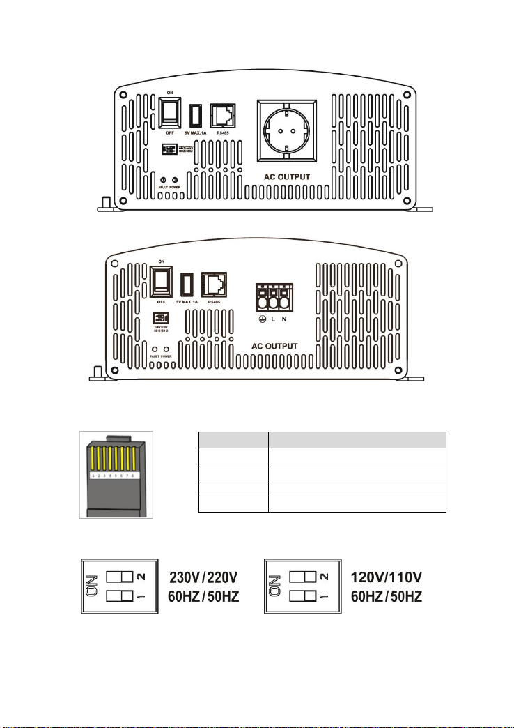
(3) AC Outlet (optional)
Universal
Australia/New Zealand
Page 12
9
European
Terminal(IP1000 and above models)
(4) RS485 communication port(IP1000 and above models optional)
The RJ45 interface pin definition:
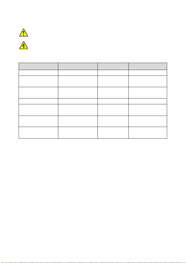
(5) Mode Switch
When switch No.1 is on the ON side, the output frequency is 60Hz. Otherwise, it is
50Hz.
When switch No.2 is on the ON side, the output voltage is 230VAC(120VAC).
Pins
Define
1/2
5VDC
3/4
RS485-B
5/6
RS485-A
7/8
GND
Page 13
10
Otherwise, it is 220VAC(110VAC).
NOTE: Turn off the inverter to reset the output frequency or output voltage.
Then, restart the inverter when the setting is complete.
WARNING: DO NOT turn ON/OFF the mode switch when the inverter is
working.
(6) LED indicator and Buzzer
Working indicator
Fault indicator
Buzzer
Status
Green On Solid
Red OFF
No Sounding
Output is normal
Green Slowly
Flashing(1/4Hz)
Red OFF
Sounding
Input under-voltage
Green Fast
Flashing(1Hz)
Red OFF
Sounding
Input overvoltage
Green On Solid
Red ON Solid
Sounding
Over-temperature
Green OFF
Red Fast
Flashing(1Hz)
Sounding
Load short circuit
Green On Solid
Red Slowly
Flashing(1/4Hz)
Sounding
Overload
Green OFF
Red OFF
Sounding
Output voltage
abnormal
Page 14

11
6. Protection
Protection
and recover
Condition
Phenomenon
Parameter
IPower-1*
IPower-2*
IPower-4*
Overvoltage
protection
and recover
Input Voltage
Ui
Ui>16V
Ui>32V
Ui>64V
Output is OFF
Green indicator fast
flashing
Buzzer sounds
Ui≤14.5V
Ui≤29V
Ui≤58V
Green indicator on
solid
The output is on
Low voltage
protection
and recover
Input Voltage
Ui
Ui<10.8V
Ui<21.6V
Ui<43.2V
Output is OFF
Green indicator slowly
flashing
Buzzer sounds
Ui≥12.5V
Ui≥25V
Ui≥50V
Green indicator on
solid
The output is on
Over-tempera
ture protection
and recover
Tem. (T)
Heat sink T>80℃(IP1000 T>
75℃)
or Internal T>60℃
Inverter turns OFF
Heat sink T≤70℃(IP1000
T≤65℃)
and Internal T≤50℃
Inverter turns ON
Overload
protection
and recover
S: Output
power
Pe: Rated
power
S=1.2P
e①
The output is OFF
after 15min
Red indicator slowly
flashing
Buzzer sounds
S=1.5P
e
①
The output is OFF
after 30s②
Red indicator slowly
flashing
Buzzer sounds
S=1.8P
e
①
The output is OFF
after 10s
Page 15

12
Red indicator slowly
flashing
Buzzer sounds
S>2Pe(Rated input voltage)
①
The output is OFF
after 5s
Red indicator slowly
flashing
Buzzer sounds
Load short circuit protection①
The output is OFF
immediately
Red indicator fast
flashing
Buzzer sounds
① When output overload protection or load short circuit protection is activated, the
AC output would auto-recovery three times (the first time delays for 5s, the
second time delays for 10s, and the third time delays for 15s). After three
attempts, the AC output would not auto-recover. It can only be recovered after
restarting the inverter. (When S=1.2Pe, the models don't have the auto-recovery
function, except IP350 and IP500.)
② IP350 and IP500 stop output after 1minute.
Page 16

13
7. Troubleshooting
Faults
Possible
reasons
Troubleshooting
Green indicator slowly
flashing
Buzzer sounds
DC input
under-voltage
Measure the DC input voltage if the
voltage is lower than 10.8/21.6/43.2V.
Adjust the input voltage to restore
normally.
Green indicator fast
flashing
Buzzer sounds
DC input
overvoltage
Measure the DC input voltage if the
voltage is higher than 16/32/64V. Adjust
the input voltage to restore normally.
Red indicator slowly
flashing
Buzzer sounds
Overload
Reduce the number of AC loads.
Restart the inverter.
Red indicator fast
flashing
Buzzer sounds
Short circuit
Check carefully loads connection,
clear the fault.
Restart the inverter.
Green and red
indicator on solid
Buzzer sounds
Over-temperature
When the heat sink temperature
exceeds 80℃or the internal
temperature exceeds 60℃, the inverter
automatically turns off the output. When
the heat sink temperature goes below
70℃or the internal temperature goes
below 50℃; the inverter resumes work.
Page 17

14
8. Maintenance
The following inspections and maintenance tasks are recommended at least two
times per year for best performance.
Make sure no block on airflow around the inverter. Clear up any dirt and fragments on
the radiator.
Check all the naked wires to ensure insulation is not damaged for serious
solarization—frictional wear, dryness, insects or rats, etc. Repair or replace some wires
if necessary.
Check and confirm that indicator and display are consistent with required. Pay
attention to any troubleshooting or error indication. Take corrective action if necessary.
Confirm that all the terminals have no corrosion, insulation damage, high temperature,
or burnt/discolored sign, tighten terminal screws to the suggested torque.
Check for dirt, nesting insects, and corrosion. If so, clear up in time.
Check and confirm that the lightning arrester is in good condition. Replace a new one
in time to avoid damaging the inverter/charger and even other equipment.
WARNING: Risk of electric shock!
Risk of electric shock! Before the above operations, ensure that all the power is turned off.
The electricity in the capacitances is completely discharged, then follows the corresponding
inspections.
Page 18

15
9. Disclaimer
The warranty does not apply under the following conditions:
Damage caused by improper use or use in an inappropriate environment
Battery voltage exceeds the input voltage limit of the inverter
Damage caused by working environment temperature exceeds the rated range
Unauthorized dismantling or attempted repair
Damage occurred during transportation or handling
Damage caused by force majeure
Page 19
16
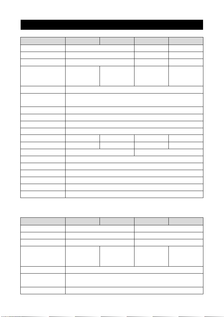
10. Technical Specification
Item
IP350-11
IP350-12
IP350-21
IP350-22
Rated Input Voltage
12VDC
24VDC
24VDC
Input Voltage Range
10.8~16VDC
21.6~32VDC
21.6~32VDC
Input surge voltage
<32VDC
<44VDC
<44VDC
Output Voltage
110VAC(±5%)
120VAC(-10%~
+5%)
220VAC(±5%)
230VAC(-7%~+
5%)
110VAC(±5%)
120VAC(-10%~
+5%)
220VAC(±5%)
230VAC(-7%~+
5%)
Output Frequency
50/60±0.1Hz
Output Continuous
Power
280W
Output Power 15 min.
350W
Surge power
750W
Power factor
0.2-1(VA lower than output continuous power)
Output Wave
Pure sine wave
Distortion THD
THD≤5%
①
THD≤3%
①
THD≤5%
①
THD≤3%
①
Max. Efficiency
90%
91%
91%
92%
No-load current
<0.7A
<0.5A
USB Output Port②
5VDC/Max.1A
Binding post
Φ6mm
Dimension
214×105.5×57.7mm
Mounting size
185.5×76.7mm
Mounting hole size
Φ4.2mm
Net weight
1.0kg
① Test condition: Rated Input Voltage, Output Continuous Power, Resistive load.
② Conventional products don't have this port; the port is optional.
Item
IP500-11
IP500-12
IP500-21
IP500-22
Rated Input Voltage
12VDC
24VDC
Input Voltage Range
10.8~16VDC
21.6~32VDC
Input surge voltage
<32VDC
<44VDC
Output Voltage
110VAC(±5%)
120VAC(-10%~
+5%)
220VAC(±5%)
230VAC(-10%~
+5%)
110VAC(±5%)
120VAC(-10%~
+5%)
220VAC(±5%)
230VAC(-10%~
+5%)
Output Frequency
50/60±0.1Hz
Output Continuous
Power
400W
Output Power 15 min.
500W
Page 20
17
Surge power
1000W
Power factor
0.2-1(VA lower than output continuous power)
Output Wave
Pure sine wave
Distortion THD
THD≤5%
①
THD≤3%
①
THD≤5%
①
THD≤3%
①
Max. Efficiency
91%
92%
91%
92%
No-load current
<0.9A
<0.5A
USB Output Port②
5VDC/Max.1A
Binding post
Φ6mm
Dimension
232.2×132×74.5mm
Mounting size
205×102mm
Mounting hole size
Φ5.2mm
Net weight
1.7kg
① Test condition: Rated Input Voltage, Output Continuous Power, Resistive load.
② Conventional products don't have this port; the port is optional.
Item
IP1000-11
IP1000-12
IP1000-21
IP1000-22
Rated Input Voltage
12VDC
24VDC
Input Voltage Range
10.8~16VDC
21.6~32VDC
Input Surge Voltage
<20VDC
<44VDC
<40VDC
Output Voltage
110VAC/120VA
C(±3%)
220VAC/230VA
C (±5%)
110VAC/120VA
C(±3%)
220VAC/230VA
C (±5%)
Output Frequency
50/60±0.1Hz
Output Continuous
Power
800W
Output Power 15 min.
1000W
Surge power
1600W
Power factor
0.2-1(VA lower than output continuous power)
Output Wave
Pure sine wave
Distortion THD
THD≤5%
①
THD≤3%
①
THD≤5%
①
THD≤3%
①
Max. Efficiency
92.5%
94.5%
92.5%
94.5%
No-load Current
<0.8A
<0.5A
USB Output Port②
5VDC/Max.1A
RS485 Com. Port②
5VDC/200mA
Binding Post
Φ6mm
Dimension
298.3×231.5×98.5mm
284.7×231.5×98.5mm
Mounting size
183×220mm
163×219.5mm
Mounting hole size
Φ5.5mm
Net Weight
3.9kg
3.6kg
① Test condition: Rated Input Voltage, Output Continuous Power, Resistive load.
Page 21
18
② Conventional products don't have this port; the port is optional.
Item
IP1500-11
IP1500-12
IP1500-21
IP1500-22
Rated Input Voltage
12VDC
24VDC
Input Voltage Range
10.8~16VDC
21.6~32VDC
Input Surge Voltage
<20VDC
<40VDC
Output Voltage
110VAC(±3%)
120VAC(-7%~+
3%)
220VAC(±5%)
230VAC(-7%~+
5%)
110VAC(±3%)
120VAC(-7%~+
3%)
220VAC(±5%)
230VAC(-7%~+
5%)
Output Frequency
50/60±0.1Hz
Output Continuous
Power
1200W
Output Power 15 min.
1500W
Surge power
2400W
Power factor
0.2-1(VA lower than output continuous power)
Output Wave
Pure sine wave
Distortion THD
THD≤5%
①
THD≤3%
①
THD≤5%
①
THD≤3%
①
Max. Efficiency
93%
94%
No-load Current
<1.0A
<0.6A
USB Output Port②
5VDC/Max.1A
RS485 Com. Port②
5VDC/200mA
Binding Post
Φ6mm
Dimension
326.12×231.5×98.5mm
284.7×231.5×98.5mm
Mounting size
208×220mm
163×219.5mm
Mounting hole size
Φ5.5mm
Net Weight
4.6kg
3.9kg
① Test condition: Rated Input Voltage, Output Continuous Power, Resistive load.
② Conventional products don't have this port; the port is optional.
Item
IP2000-21
IP2000-22
IP2000-41
IP2000-42
Rated Input Voltage
24VDC
48VDC
Input Voltage Range
21.6~32VDC
43.2~60VDC
Input Surge Voltage
<40VDC
<80VDC
Output Voltage
110VAC(±5%)
120VAC(-10%~
+5%)
220VAC(±5%)
230VAC(-10%~
+5%)
110VAC(±5%)
120VAC(-10%~
+5%)
220VAC(±5%)
230VAC(-10%~
+5%)
Output Frequency
50/60±0.1Hz
Output Continuous
Power
1600W
Output Power 15 min.
2000W
Page 22
19
surge Power
3200W
Power factor
0.2-1(VA lower than output continuous power)
Output Wave
Pure sine wave
Distortion THD
THD≤5%
①
THD≤3%
①
THD≤5%
①
THD≤3%
①
Max. Efficiency
94%
95%
94%
95%
No-load Current
<0.6A
<0.4A
USB Output Port②
5VDC/Max.1A
RS485 Com. Port②
5VDC/200mA
Binding Post
Φ6mm
Dimension
326.12×231.5×98.5mm
Mounting size
208×219.5mm
Mounting hole size
Φ5.5mm
Net Weight
4.6kg
① Test condition: Rated Input Voltage, Output Continuous Power, Resistive load.
② Conventional products don't have this port; the port is optional.
Environmental Parameters
Working Temperature
-20℃~ +45℃
Storage Temperature
-35℃~ +70℃
Humidity
< 95%(N.C.)
Enclosure
IP20
Altitude
< 5000 m (Derating to operate according to IEC62040 at a height
exceeding 1000 m)
Others
Dielectric Strength
Between DC input terminals and metal case: Test voltage AC500V, 1 minute
Between AC output terminals and metal case: Test voltage AC1500V, 1 minute
Any changes without prior notice! Version number: V2.3
Page 23

Page 24

HUIZHOU EPEVER TECHNOLOGY CO., LTD.
Beijing Tel: +86-10-82894896/82894112
Huizhou Tel: +86-752-3889706
E-mail: [email protected]
Website: www.epever.com
 Loading...