


EF-IV I
Table of contents
 Loading...
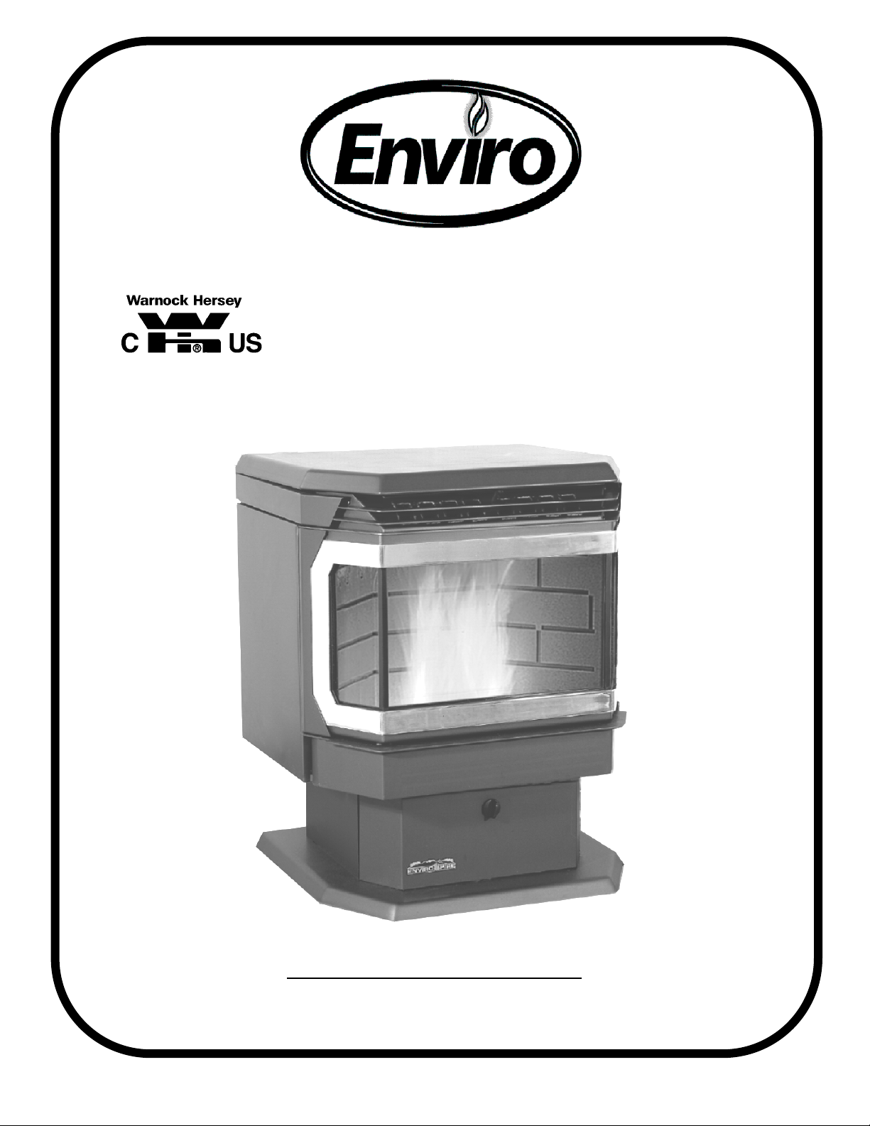
PELLET STOVE
EF-IV i
OWNERS TECHNICAL MANUAL
SHERWOOD INDUSTRIES LTD.
6782 OLDFIELD RD
VICTORIA, BRITISH COLUMBIA V8M-2A3

ENVIROFIRE INSTALLATION MANUAL
TABLE OF CONTENTS
1) INTRODUCTION
PAGE
Important Safety Data........................................................... 3
Pellet Quality ........................................................................4
Warnings and Recommendations......................................... 5
Automatic Safety Features ................................................... 5
2) OPERATION
How to Start Your Pellet Appliance....................................... 6
Turning Your Pellet Appliance Off ........................................ 6
Slider/Damper....................................................................... 7
Clip On Door Installation………………………………………..7
3) SPECIFICATIONS / MAINTENANCE
Areas for Routine Maintenance .......................................8-10
Electrical Component Functions .................................... 10-12
4) INSTALLATION
Vent Termination Requirements ......................................... 13
Deciding Where To Locating Your Pellet Appliance ........... 13
Removing Your New Stove From It’s Pallet........................ 14
Fireplace Dimensions ......................................................... 14
Masonry Fireplace Insert Installation .................................. 15
Assembling the Face Plate for the FPI Models................... 16
Model FS (Freestanding) Installation.............................17-22
Pedestal Installation ........................................................... 18
Horizontal Exhaust through the Wall .............................19-20
Inside Vertical Pipe Installation........................................... 21
Outside Vertical Pipe Installation ........................................ 22
Mobile Home Installation ....................................................23
Outside Fresh Air Connections........................................... 23
5) SERVICE
Troubleshooting.............................................................24-27
Wiring Diagram................................................................... 28
Parts List ............................................................................ 29
Exploded Views ............................................................. 30-31
Warranty............................................................................. 32
2

IMPORTANT SAFETY DATA
To prevent the possibility of a fire, ensure that the appliance is properly installed by adhering to the
installation instructions. An ENVIROFIRE dealer will be happy to assist you in obtaining information
with regards to your local building codes and installation restrictions.
The stove’s exhaust system works with negative combustion chamber pressure and a slightly positive
chimney pressure, it is very important to ensure that the exhaust system be sealed and airtight.
This unit is designed to burn pelletized wood fuel only. Do not use any other type of fuel, this will void
any warranties stated in this manual.
THE USE OF CORDWOOD IS PROHIBITED BY LAW.
Do not burn with insufficient combustion air. A periodic check is recommended to ensure proper
combustion air is admitted to the combustion chamber. Setting the proper combustion air is achieved
by adjusting the slide damper located on the left side of the stove.
It is advisable to clean the exhaust vent bi-annually or every two tons of pellets.
The grounded electrical cord should be connected to a standard 115 volts, 60-hertz electrical outlet. Be
careful that the electrical cord is not trapped under the appliance and that it is clear of any hot surfaces
or sharp edges. This unit’s maximum power requirement is 520 watts (4.52 Amps) for the EF-IV Bi.
Minor soot or creosote may accumulate when the stove is operated under incorrect conditions such as
an extremely rich burn (black tipped, lazy orange flames).
When installing the stove in a mobile home, it must be electrically grounded to the steel chassis of the
home and bolted to the floor. Make sure that the structural integrity of the home is maintained.
Be sure to maintain the structural integrity of home when passing a vent through walls, ceilings, or
roofs.
The ash pan must be locked securely for proper and safe operation of the pellet stove.
If you have any questions with regards to your stove or the above-mentioned information, please feel
free to contact your local dealer for further clarification and comments.
Since Sherwood Industries Ltd. has no control over the installation of your stove, we grant no warranty
implied or stated for the installation or maintenance of your stove, therefore, Sherwood Industries Ltd.
assumes no responsibility for any consequential damage.
SAVE THIS INSTRUCTION MANUAL FOR FUTURE REFERENCE
3

PELLET QUALITY IS IMPORTANT, PLEASE READ THE
FOLLOWING PAGE
Your pellet stove has been designed to burn wood pellets only. Since there are many manufacturers of
wood pellets it is important to select pellets that are free of dirt or any impurities. The Pellet Fuel
Industries (P.F.I.) has established standards for wood pellet manufactures. We recommend the use of
pellets that meet or exceed these standards. Ask your dealer for a recommended pellet type.
THE PERFORMANCE OF YOUR PELLET STOVE IS GREATLY EFFECTED BY THE TYPE AND
QUALITY OF WOOD PELLETS BEING BURNED. AS THE HEAT OUTPUT OF VARIOUS QUALITY
WOOD PELLETS DIFFER, SO WILL THE PERFORMANCE AND HEAT OUTPUT OF THE PELLET
STOVE.
Since Sherwood Industries Ltd. has no control over the quality of pellets that you use, we assume no
liability caused by the quality of wood pellets used.
P.F.I. PELLET STANDARDS:
Fines ..................................... 1% maximum through a 1/8” screen
Bulk Density .......................... 40 lbs. per cubic foot minimum
Size ....................................... 1/4” to 3/8” diameter 1 – 1.5” long maximum
Ash Content ..........................1% maximum
Moisture Content................... 8% maximum
Heat Content......................... approximately 8200 Btu per lb. minimum
Check the burn-pot liner periodically to ensure that the holes are not blocked with clinkers, (clinkers are
silica in the fuel that will form a hard mass during the burning process). If they are blocked, remove the
liner (when the unit is cold) and clean the clinkers out. The liner should be cleaned or scraped once
every 2-3 days depending on wood pellet quality. Clean the holes in the lines with a small pointed
object.
Store pellets at least 36” (1 m) away from the pellet stove.
4

WARNINGS AND RECOMMENDATIONS
A. Do not abuse the glass by striking or slamming the door shut.
B. Do not attempt to operate the stove with broken glass.
C. Do not attempt to open the door and clean the glass while the unit is in operation. To clean the
glass, use a soft cotton cloth and mild window cleaner, gas or wood stove glass cleaner or take
a damp paper towel and dip into the fly ash, this is a very mild abrasive and will not damage the
glass.
D. Do not use abrasive cleaners to clean the surface or any part of the stove.
E. It is recommended that the unit be secured into its position in order to avoid any displacement.
F. Never use gasoline, gasoline-type lantern fuel, kerosene, or similar liquids to start the fire. Keep
all such liquids well away from the pellet stove while it is in use.
G. Disposed ashes should be placed in a metal container with a tight fitting lid. The closed
container of ashes should be on a non-combustible floor on the ground, well away from all
combustible materials pending final disposal. The ashes should be retained in the closed
container until all cinders have thoroughly cooled before disposing of them.
H. Make sure the ash pan is closed tightly during the operation of the stove.
I. KEEP ASH PAN FREE OF RAW FUEL. DO NOT PLACE UNBURNED OR NEW PELLET
FUEL IN ASH PAN. A fire in the ash pan could be the result.
J. Fresh air intake is strongly recommended. Failure to install Intake air may result in the unit
smoking during power failures as well as improper combustion.
NOTE:
Fresh air is mandatory on all units installed in “Mobile Homes” as well as “Air
Tight” homes.
AUTOMATIC SAFETY FEATURES OF YOUR PELLET STOVE
A. The stove will shut off when the fire goes out and the exhaust temperature drops below 120°F
(49°C).
B. The stove has a high temperature safety switch. If the temperature on the hopper reaches
200°F (93°C) the auger will automatically stop, and the stove will shut down when the exhaust
temperature cools. If this happens call your local dealer to reset the 200°F (93°C) high limit
switch.
ALSO FIND THE REASONS WHY THE UNIT OVERHEATED.
C. The unit has a convection fan control over-ride. This function causes the convection fan to
reach its full speed when the temperature at the back of the firebox reaches 160°F (71°C). This
is a normal safety feature of your unit. To compensate for the fan cycling action that may occur,
turn up the blower control proportionately to the heat output.
D. If the power goes out, the unit will stop running. When the power comes back on, the stove will
not restart unless the exhaust temperature is still above 120°F (49 °C).
5
HOW TO START AND OPERATE YOUR PELLET APPLIANCE
Dial-A-Fire
Heat Output
Knob
Knob B
Start-up
Switch
Auger Light
Convection
Blower Speed
Control
KNOB A
1. Check and fill hopper with pellets.
2. Make sure unit is plugged into a
working outlet.
3. Switch the power “ON” by pushing the
start up switch once only.
4. Turn knob “B” to the 12 o’clock
position. (Lower grade pellets may
need a higher setting on the feed
rate). NOTE: unit will take longer to
light if the hopper has been completely
emptied.
5. Wait until the fire is established, then
turn knob “B” to the desired heat
output. (The stove may not be able to
burn in the BLUE ZONE if poor quality
wood pellets are being used. Adjust the
Slider Damper to the appropriate
setting (SEE PAGE 8).
6. If the stove should shut off after 15 minutes and there is still a fire in the firebox – press the start
up switch once more. If the fire went out, return to step number 2 and re-light the stove.
KNOB “A”:
Fan Controller. By adjusting the knob you will vary the rate of airflow into the room by
varying the speed of the convection blower. When you first start the stove it should be placed in the
“OFF” position in order to heat the unit as quickly as possible. Once the room has come up to
temperature the control may be set to a comfortable level. *Note: The convection blower may cycle to
high automatically depending on the setting of knobs “A” and “B”. This is a normal safety feature of the
unit.
The flashing green “Auger Light”
corresponds to the timing of the auger turning .
KNOB “B”:
Dial a Fire Heat Output Knob. This knob controls the amount of heat output. The dial has a
scale with the blue zone representing the coolest setting of the stove, and the red zone representing
the hottest setting. The scale on knob “B” represents a range, not exact at times or fuel quantities.
Wood pellets of differing quality may effect the performance of the stove. If the stove has trouble
operating at either end of its range, turn the heat output knob back slightly.
TURNING YOUR PELLET STOVE OFF
To turn your stove off, simply turn the HEAT OUTPUT knob (knob “B”) counter-clockwise until the knob
clicks to the “OFF” position. This will stop the feed of pellets. The blowers will continue to run and cool
the stove. When cool enough, the stove will shut down.
6
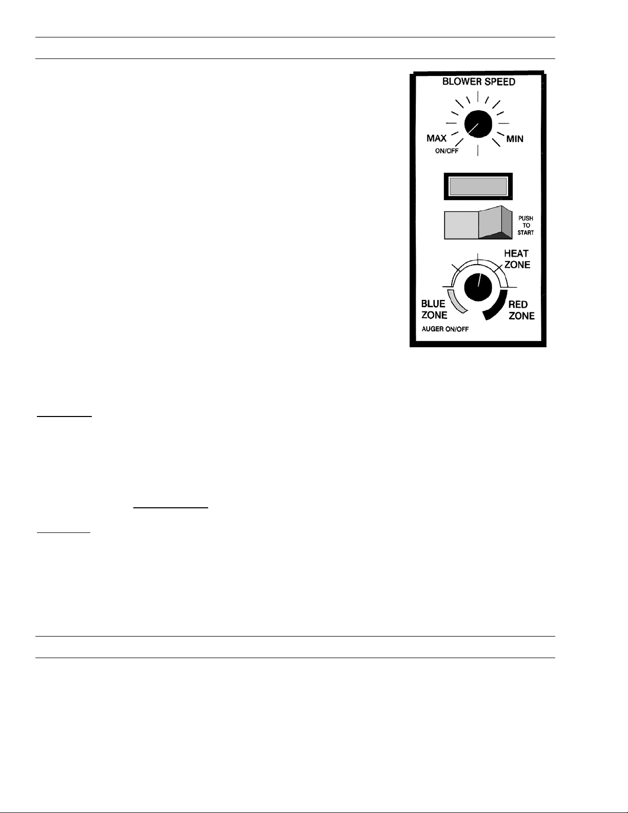
SLIDER/DAMPER INSTALLATION INSTRUCTIONS
This is used to regulate the airflow through the pellet
stove.
A Qualified Service Technician or Installer should set the
Slider Damper.
The Slider Damper is pre set from the factory. The slider
damper will be set and held in place with a 5/16” hex head
screw. This screw will be tightened in the middle of the
slot located in the slider damper plate.
The slider damper is located behind the left side panel.
To open the left side panel, undo the one screw located in
the upper front corner of the cabinet side
The combustion exhaust blower is a variable speed blower controlled by the heat output knob,(Dial a Fire). This
blower will decrease the vacuum pressure inside the stove and as the heat output knob is turned up. The vacuum
pressure inside the firebox will increase as the combustion exhaust blower increases in speed.
SPECIAL NOTES:
Pellet quality is a major factor in how the Pellet stove will operate. If the Pellets have a high moisture content or
ash content the fire will be less efficient and has a higher possibility of the fire building up and creating clinkers.
(hard ash build-up)
If the fire should happen to go out and the Dial A Fire has been set on the lowest setting, the Slider Damper
should be pushed in slightly decreasing the air in the firebox.
If after long periods of burning the fire builds up and over flows the burn pot or there is a build up of clinkers This
would be a sign that the pellet quality is poor and the slider damper must be pulled out to compensate.
Pulling the slider damper out gives the fire more air.
The easiest way to make sure that an efficient flame is achieved is to see the characteristics of the fire.
• A tall and lazy flame with dark orange tips requires more air – Open slider / damper up.
• A short and brisk flame, like a blowtorch, has too much air – Close slider / damper down.
• If the flame is in the middle of these two characteristics with a bright yellow/orange, active flame then the air is
set for proper operation.
CLIP ON DOOR INSTALLATION
1. Unlatch door and swing open, remove door
form unit.
2. Place door on a soft flat surface and remove
the (4) screws (2 on each side) that hold the
side trim pieces to the door.
Side trim
pieces
2 screws per
side
Inner door
Clip on door (GOLD
or NICKEL)
3. Undo all four screws that hold the outer clip on
the door.
4. Install the new ( GOLD or NICKEL) clip on door
using the four screws to fasten to the door.
5. Reinstall the side trim pieces using the screws
that were removed from step 1.
6. Reinstall the door on the unit and latch with the
handle provided.
7
AREAS FOR ROUTINE INSPECTION
The following should be inspected periodically to ensure that the appliance is operating at its optimum and giving
you excellent heat value:
2 3 DAYS/WEEKLY SEASON or 2 TONS OF FUEL
Burn Pot and Liner Exhaust Vent
Ash Pan Fresh air Intake Tube
Inside Firebox Blower Mechanisms
Behind Firebox Liners Heat exchanger tubes
Burn Pot and Liner Latch Mechanism of ash pan
Door Glass Door Latch
Heat exchanger tubes All Hinges
Ash pan and Door gaskets Post Season Clean-up
TOOLS REQUIRED TO CLEAN UNIT:..Torx T-20 Screwdriver, Brush, Soft Cloth, Vacuum with fine filter bag
ASH PAN AND DOOR GASKETS
After excessive use the gasketing may come loose. To repair this, glue the gasketing on using high-temperature
fiberglass gasket glue available from your local dealer. This is important to maintain an airtight assembly. DO
NOT PLACE UNBURNED OR RAW PELLET FUEL IN ASH PAN.
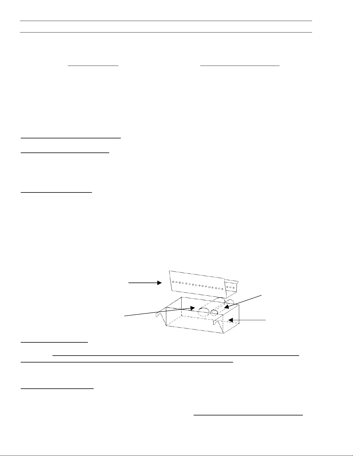
BURNER POT AND LINER
This is the ‘pot’ where the pellets are burned. Every two to three days (when the unit is cold), remove the burn-
pot liner from the stove. Using a metal scrapper remove material that has accumulated or is clogging the liner’s
holes. Then dispose of the scrapped ashes from the liner and from inside the burn-pot. Place the burn-pot back
into the stove, making sure that the pipes are properly inserted into the burn pot and the front tabs are in place in
the firebox. Place the liner back into the burn-pot, making sure that the ignitor hole in the liner is aligned with the
ignitor tube. Pushing the liner up against the igniter tube.
To remove the burn pot and burn pot liner open the door using the door handle provided located on the left-hand
side of the stove, swing the door open. Lift the liner from the burn pot, lift the burn pot from the firebox by gently
lifting the front of the burn pot up first then sliding the assembly from the air intake tube and the igniter cartridge.
IGNITER TUBE
FRESH AIR
TUBE
BURN POT
BURN POT
LINER
INSERT ASH REMOVAL:
The EF 4 pellet stove insert does not have an ash pan and the ashes must be vacuumed out of the firebox on a
daily basis. CAUTION: BECAUSE THE FLY ASH IS VERY FINE, THE USE OF A VACUUM BAG WILL BE
REQUIRED TO PREVENT ASH FROM BEING BLOWN BACK INTO THE ROOM. Please pay special
attention that there are no hot ashes in the firebox or there could be a possibility of a fire hazard inside
the vacuum cleaner. Place all hot ashes into a noncombustible container.
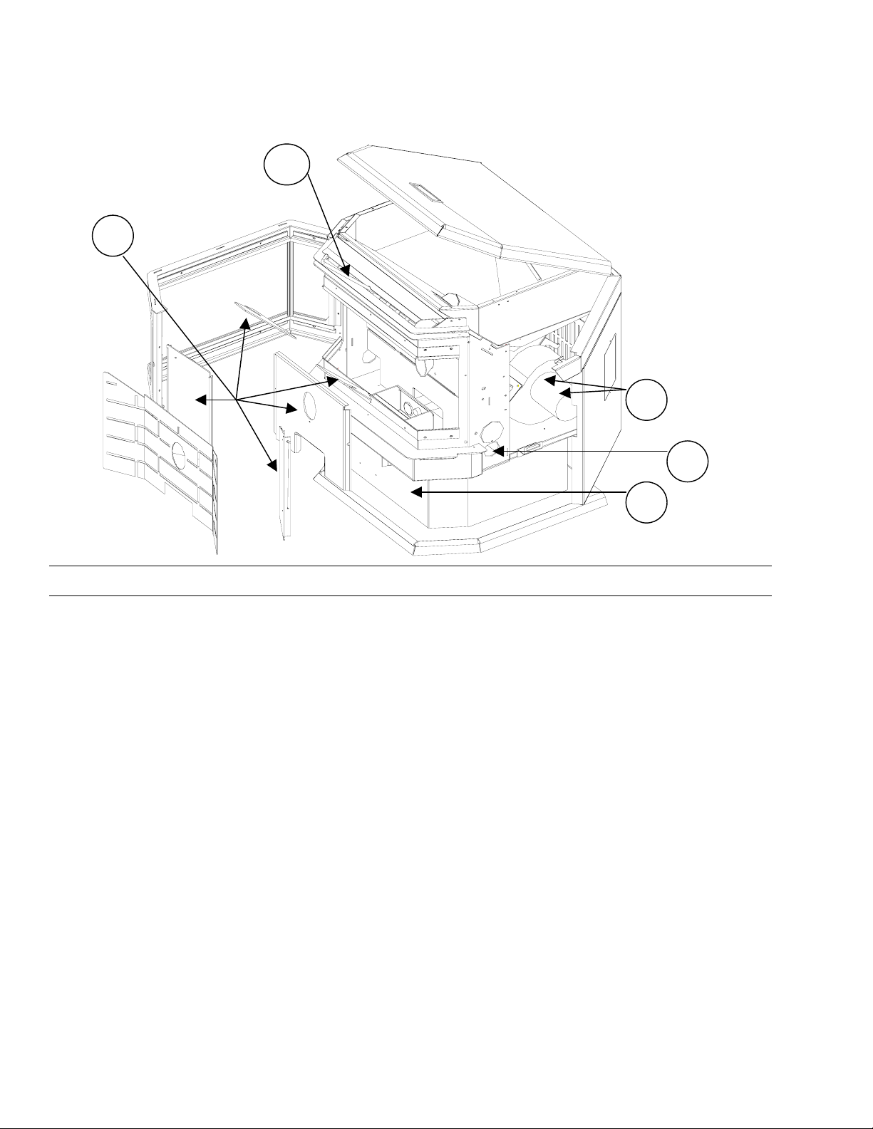
FREESTANDING ASH PAN
: ( # 1 SEE PAGE 10)
This part is located under the burner, in the pedestal and has a latching mechanism to secure it. To remove the
ash pan, unlock the latch on the pedestal cover and then pull the pan out. Dump the ashes into a metal container
stored away from combustibles. Monitor the ash level every week. Remember that different pellet fuels will
8

have different ash contents. Ash content is a good indication of fuel efficiency and quality. Refer to “Warnings
and Recommendations” for disposal of ashes.
BLOWER MECHANISMS
( # 2 SEE PAGE 10)
Unplug the stove then open the right/left side panels to access the two blowers. Only the convection blower
motor (on the right side of the stove) will require lubrication. The convection motor has two lubrication holes on it.
Use two drops of SAE 20, light oil to lubricate every six months. Excess oil may damage the motor. The exhaust
blower’s motor has sealed bearings, DO NOT
lubricate this motor.
DOOR GLASS
(It is recommended that your dealer replace the glass if broken.)
The door glass is made of high temperature PYROCERAMIC The center panel is 246mm x 383mm and the two
outside pieces are 246mm x 107mm. To replace the glass, unscrew and remove the four glass retainers.
Remove the glass and any broken pieces. High temperature fiberglass tape should be used around the glass.
Replace the glass, then screw the glass retainers back to the frame.
FRESH AIR INTAKE
Inspect periodically to be sure that it is not clogged with any foreign materials.
EXHAUST PASSAGES
( # 3 SEE PAGE 10)
For BI-weekly clean out, ash may be removed from behind the steel plates by rotating the circular covers located
behind the right and left side panels. To open the side panels undo one T20 Torx screw on each side( TOP,
FRONT). When the side cabinet doors have been opened there are two round disks at the bottom of the firebox,
loosen the screw on the disks and open, this will allow vacuuming behind the firebox liners plates.
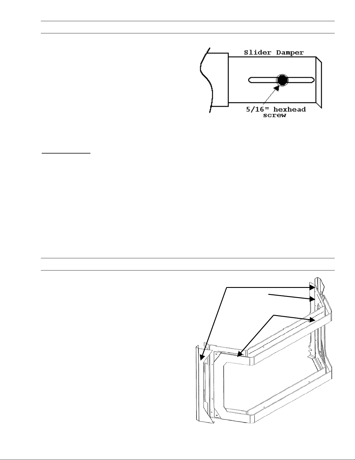
Removal of the fire box backing for BI-annual cleaning ( # 4 SEE PAGE 10)
-Open the door with the handle provided, Remove the burn pot and burn pot liner.
-Lubricate all screws with penetrating oil.
-Undo the four screws and remove the firebrick liner.
-Remove the two top baffles.
- Just above the ash sill there are two screws that hold the firebox liners in place, remove these two
screws.
-With the tip of a flat screwdriver, gently lift up the side panels and remove the side panels.
-Pull the center panel out.
-Vacuum thoroughly.
Installation of fire box backing:
-Insert center panel.
-Place the side panels back into the firebox and reinstall the two lower screws, Install top baffles.
-Replace the firebrick liner.
-Replace the glass door and secure.
-Clean thoroughly.
EXHAUST VENT
This vent should be cleaned every year or after two tons of pellets. We recommend contacting your dealer for
professional cleaning. To clean the vent pipe, tap lightly on the pipe to dislodge any loose ash. Open the bottom
of the ”T” to dump the ash, then vacuum as much of the ash out of the vent pipe as possible.
HEAT EXCHANGER TUBES
(#5 SEE PAGE 10)
A handle is located under the hopper lid, in the center of the stove just above the door. This handle is to be pulled
up and down a few times (ONLY WHEN THE UNIT IS COLD) in order to clean away any fly ash that may have
collected on the heat exchanger tubes. As different types of pellets produce different amounts of ash, cleaning of
the tubes should be done on a regular basis to enable the unit to run efficiently.
POST SEASON CLEAN-UP
9
Once you are finished using the pellet appliance for the season, unplug the stove for added electrical protection.
It is very important that the stove be cleaned and serviced as stated above. (See Section Areas of Routine
Inspection)
5
4
3
2
1
ELECTRICAL COMPONENT FUNCTIONS
The following is a list of electrical components and their functions on the ENVIROFIRE EF-IVi pellet stove.
1. CONVECTION FAN CONTROLLER
This controller is responsible for varying the speed of the convection blower. Should the convection blower be set
on low and dial-a-fire set on high, the 160ºF (71ºC) Temp. Sensor will by-pass the fan controller and the fan will
go to full speed. This will cool the stove until control is given back to the fan controller
2. AUGER PULSE LIGHT
This light will flash in conjunction with the pulses to the auger.
3. START-UP SWITCH
When this momentary contact switch is pressed it will initiate the 15-minute start-up cycle including the ignitor.
4. DIAL-A-FIRE (HEAT OUTPUT CONTROL)
This unit is responsible for controlling the timing of the auger motor. When turned clockwise it will cause the OFF
time between auger pulses to shorten, resulting in more heat output and pellet consumption. Turn the knob
counter-clockwise and the reverse will happen. When it is turned fully counter-clockwise past the click, the auger
motor will be off. This component also controls the exhaust blower speed Via the Speed Control Module
5. CONVECTION BLOWER
This blower fan,(mounted on the right side of the stove) draws room air from the back of the stove and passes the
air through the heat exchanger tubes and back into the room. The sealed system keeps the room air separate
from the combustion air. The convection blowers fan controller controls this fan’s speed.
10
Loading...