

Page 1
ADVANCED TECHNICAL MANUAL
Part #: 265888
Universal Control Card
Form# E-UCCMAN1012
Page 2

Part #: 265888
Universal Control Card
Advanced Technical Manual
TABLE OF CONTENTS
PRODUCT OVERVIEW ................................................................................................................................................................3
FEATURES ....................................................................................................................................................................................3
CONTROL MODES ....................................................................................................................................................................... 4
ELECTRICAL SPECIFICATIONS .................................................................................................................................................. 6
Test Probe Jacks .................................................................................................................................................................... 6
LED Indicators ........................................................................................................................................................................ 6
Signal Details ......................................................................................................................................................................... 6
RJ-45 Network Cable Connections ........................................................................................................................................ 6
COMMUNICATION SPECIFICATIONS ......................................................................................................................................... 7
Overview ................................................................................................................................................................................ 7
MODBUS Register Specications .......................................................................................................................................... 7
2 Innovators in Clean Air Technology | www.envirco.com
Page 3
Part #: 265888
MANUAL SPEED POT
RPM TEST PROBE JACK "COM"
Universal Control Card
Advanced Technical Manual
PRODUCT OVERVIEW
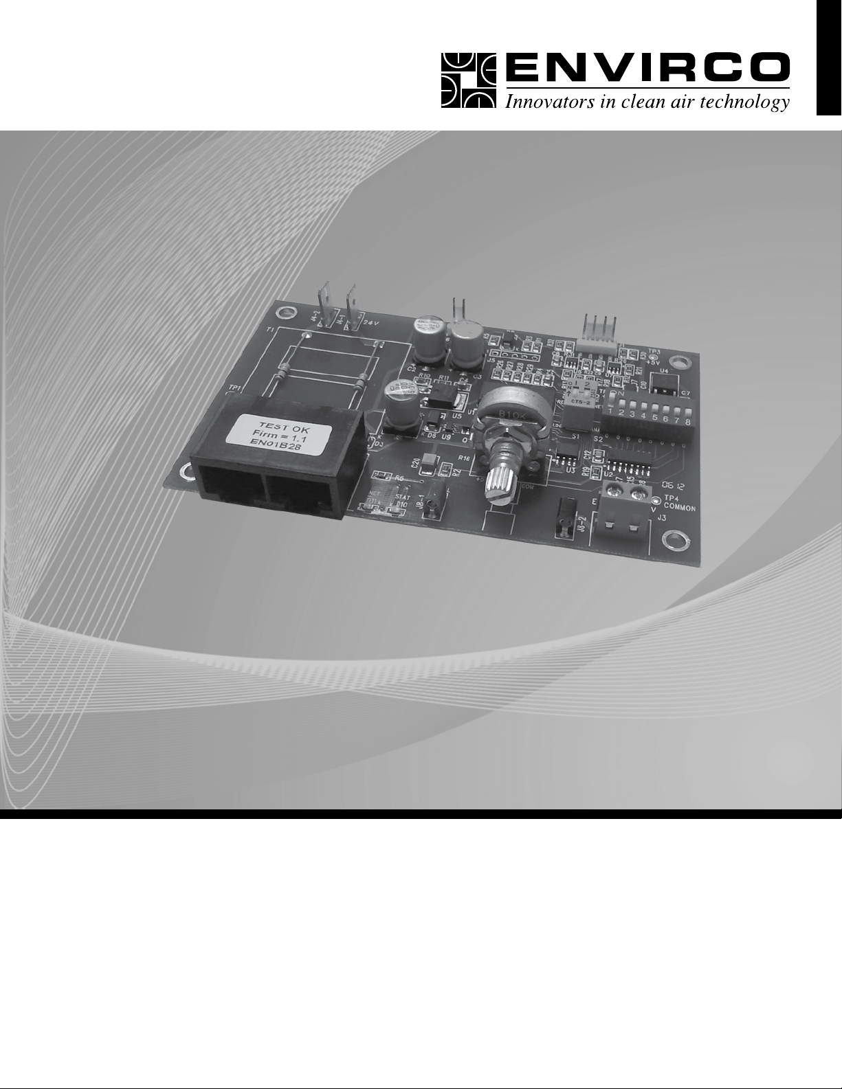
Envirco’s ENV1028 Universal Control Card provides MODBUS network and analog control capabilities to an Envirco Fan Filter Unit
equipped with an electrically commutated motor. Three different control modes provide installation versatility by allowing the FFU to
be controlled via MODBUS RTU network, analog 0-10 VDC control signal, or by adjusting the onboard potentiometer. The ENV1028
Universal Control Card is fully compatible with all of Envirco’s plug & play System Control Consoles using MODBUS RTU. Additional
details of the controls modes are provided on page 4.
FEATURES
• Networkable Via MODBUS RTU
• 0-10 VDC Analog Control
• Manual Control Via Onboard Potentiometer
• Simple Connections
• RJ45 For Networking Connection
• Screw Terminals For Analog Control
• Test Probe Jacks For DC mV Signal Output Of The Following...
• RPM
• Motor Control Set Point
• LED Diagnostics
• Support for external LED (10mA) remote status notication via 2 Pin MTA connector
• Onboard green LED for Board Status notication
• Onboard red LED for Network Trafc
• Powered from Network or Local Supply
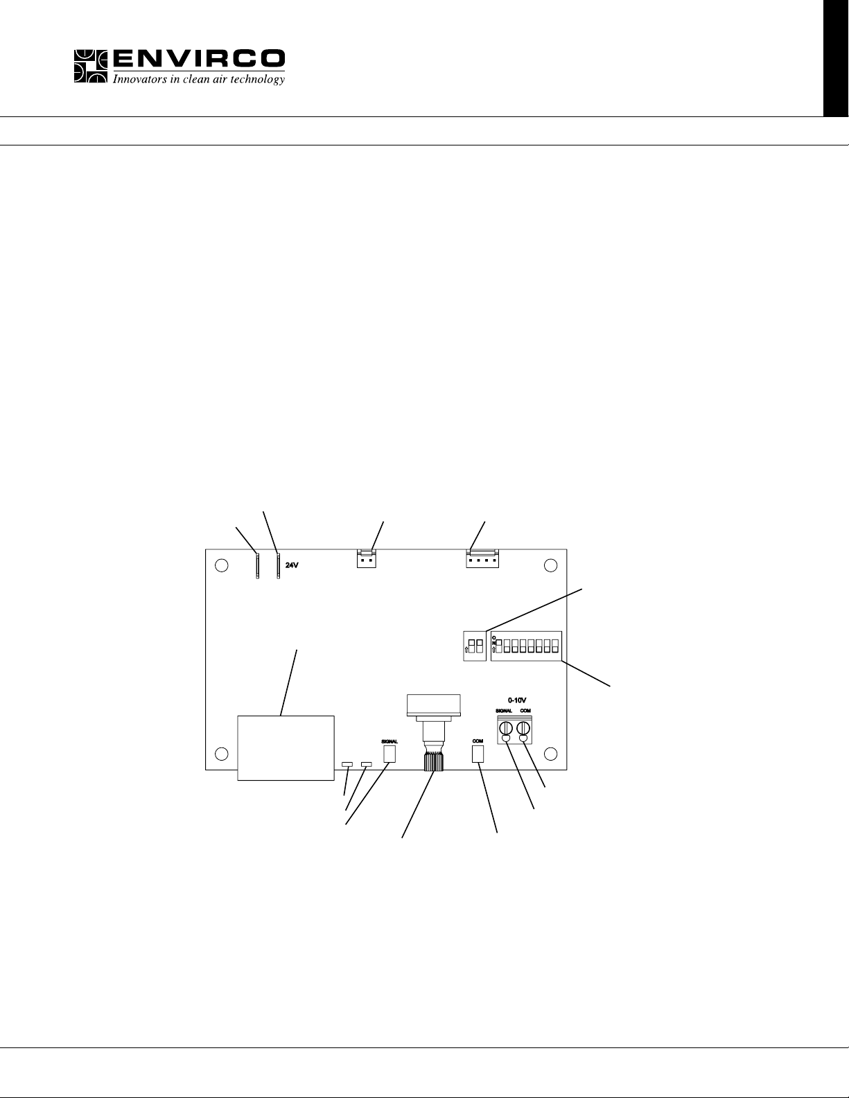
INCOMING POWER 24VAC
COMMON
DUAL RJ-45 JACKS FOR CAT 5 CABLE
RED LED FOR NET ACTIVITY
GREEN LED FOR SYSTEM/RPM STATUS
RPM TEST PROBE JACK "SIGNAL"
LED CONNECTOR
CONTROL HARNESS CONECTOR
CONTROL DIP SWITCH
1 1 2 3 4 5 6 7 82
ANALOG INPUT "COM"
ANALOG INPUT "SIGNAL"
ADDRESSING DIP SWITCH
3Innovators in Clean Air Technology | www.envirco.com
Page 4
Part #: 265888
Universal Control Card
Advanced Technical Manual
CONTROL MODES
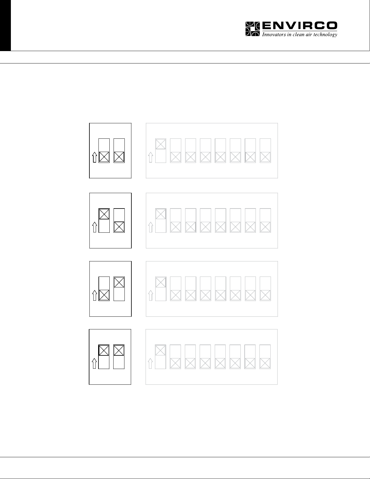
The ENV1028 operates in one of three selectable modes. The Mode is selected using DIP Switch S1.
• MANUAL control, on-board potentiometer
• ANALOG control, Remote 0-10 VDC
• NETWORK control, MODBUS RTU
Manual Mode = 1 OFF 2 OFF
ON ADE02
1 3 4 5 6 7 8
O
N
1
2
Analog Mode = 1 ON 2 OFF
ON ADE02
1 3 4 5 6 7 8
O
N
1
2
Network Mode = 1 OFF 2 ON
ON ADE02
1 3 4 5 6 7 8
O
N
2
2
2
1
2
Network Mode = 1 ON 2 ON
ON ADE02
1
2
Note:NetworkmodecanbeconguredusingeitherDIPswitchsettingshownabove.
4 Innovators in Clean Air Technology | www.envirco.com
1 3 4 5 6 7 8
2
O
N
Page 5
Part #: 265888
Universal Control Card
Advanced Technical Manual
ManualControlMode:
In Manual control mode, the motor speed is set using the onboard potentiometer. Onboard potentiometer rotation is CW to increase
the motor output.
AnalogControlMode:
In ANALOG control mode, the motor output is set using an external 0-10 VDC demand signal.
NetworkControlMode:
In NETWORK control mode, the motor output is set using MODBUS Register 2. Motor output is specied as a value from 0 to 100
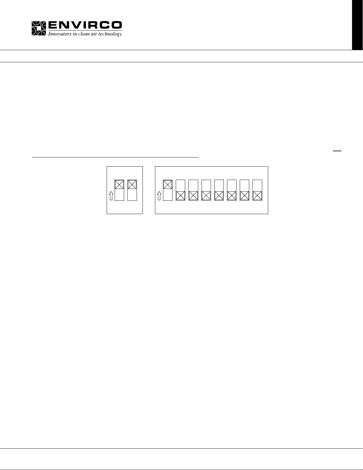
representing a percentage of motor torque output. Each ENV1028 in a MODBUS network must be set to a unique address. The address value is set in binary using the eight DIP switches of switch bank (S2). A maximum of 200 ENV1028 devices is recommended
per local area network(LAN). If an Envirco ACC Control Console is the MODBUS master, then addresses should be assigned within
the address range supported by the Control Console. Address zero should not be used as it is reserved for global commands. Address switch settings are only checked by the ENV1028 at power-up. Power must be cycled (OFF/ON) before any changes take
effect.
ON ADE02
1 3 4 5 6 7 8
2
O
N
1
2
Control Mode
DIP Switches
Registers relevant to this mode:
• Register 1 “Start/Stop” (R/W)
– To enable motor, write a value of 1; To disable motor, write a value of 0
• Register 2 “Motor Set Speed” (R/W)
– Motor Target speed value. Values may be written from 0 to 100
• Register 6 “RPM” (R)
– Motor RPM. Read from the motor
• Register 12 “Actual Motor Speed Instruction” (R)
– Speed control signal applied to the motor by the ENV1028.
(R/W) = Read/Write, (R) = Read Only
Addess DIP Switches
5Innovators in Clean Air Technology | www.envirco.com
Page 6
Part #: 265888
Universal Control Card
Advanced Technical Manual
ELECTRICAL SPECIFICATIONS
Control and Interface Signals:
1. External Speed 0-10V Input
• Input impedance 20k Ohms.
• MIN ON-to-OFF threshold: 190mV*
• MAX OFF-to-ON threshold: 240mV*
• ON (~215mV) to 9.89V linearly scales 1 to 99% speed.
• 9.89V or more deadbands to 100% speed.
2. External LED Output
• 10mA regulated
• LED forward voltages up to 5V
3. RPM Signal
• Signal Value: mVDC = RPM
• Ex: 900mV = 900RPM
• RPM Output Range: ~ 0, 5 to 2000 RPM (0, 5mV to 2000 mV DC)
• RPM Output Resolution: 5RPM (Zero, 400 steps from 5 to 2000 RPM inclusive)
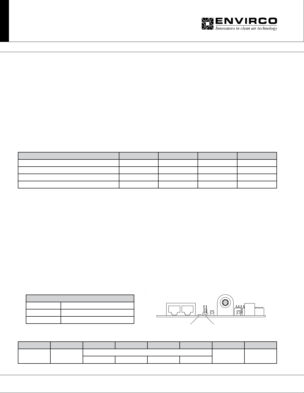
ElectricalandEnvironmentalSpecications:
Specication Min Typical Max Units
Input Voltage 22 24 42 VAC
Supply Frequency 50 50/60 60 Hz
Input Power Consumption na na 0.5 VA
Ambient Operating Temperature 0 25 50 C
TestProbeJacksPoints:
The test probe jacks may be used to measure the motor rpm or the PWM signal that is being output to the motor.
• In Manual or Analog Control Mode with an Address setting of 1 or greater, the test probe jacks output 0-2000 mVDC representing motor RPM. By changing the address DIP switches to 0, the test probe jacks will output 0-1000 mVDC representing
0-100% demand signal to the motor. The address may be changed without interrupting power to the control card.
• In Network Control Mode, 0-2000 mVDC always represents RPM.
LEDIndicators:
• Onboard Status LED:
The Onboard Status LED is software controlled by the unit microcontroller. The Status LED is solid ON when RPM reported by
the motor is greater than zero and OFF when RPM reported by the motor is zero.
• External Status LED:
Support for an external Status LED (10mA current-controlled driver), via a 2-pin MTA connector, for remote system status noti-
cation. The external Status LED operates in the same manner as the Onboard Status LED.
• Onboard Net LED:
The Onboard Net LED is driven directly by the receive data signal. The NET LED shows all network trafc on a 2-wire network.
The NET LED is intended to conrm low-level network connectivity, independent of microcontroller or rmware functionality. If
A/B network wires are swapped, the NET LED will be normally on, providing quick diagnostics of this common condition.
Net LED Status Denition
LED OFF Power Lost or No Communications
LED Flickering Network Data Trafc In Progress
LED ON A/B network wires are swapped
RJ45NetworkCableConnections:
1 2 3 4 5 6 7 8
Bus Power
Pass Through
0V (GND) RS-485 0V (GND) Bus Power
+ NC NC -
Red Network LED Green Status LED
Pass Through
6 Innovators in Clean Air Technology | www.envirco.com
Page 7
Part #: 265888
Universal Control Card
Advanced Technical Manual
COMMUNICATION SPECIFICATIONS
Overview:
• MODBUS RTU protocol over RS485 (serial)
• 9600 baud rate, word length is 8, parity is none(n), stop bits=1
• 255 unique address values selectable by DIP switch settings
• (recommended network node capacity 200 nodes)
• Slew rate limited transceivers for improved network performance MODBUS Register Summary Table
• DONOTUSECROSSOVERCABLES.THISMAYDAMAGETHECONTROLCARDORRENDERITNON-OPERATIONAL.
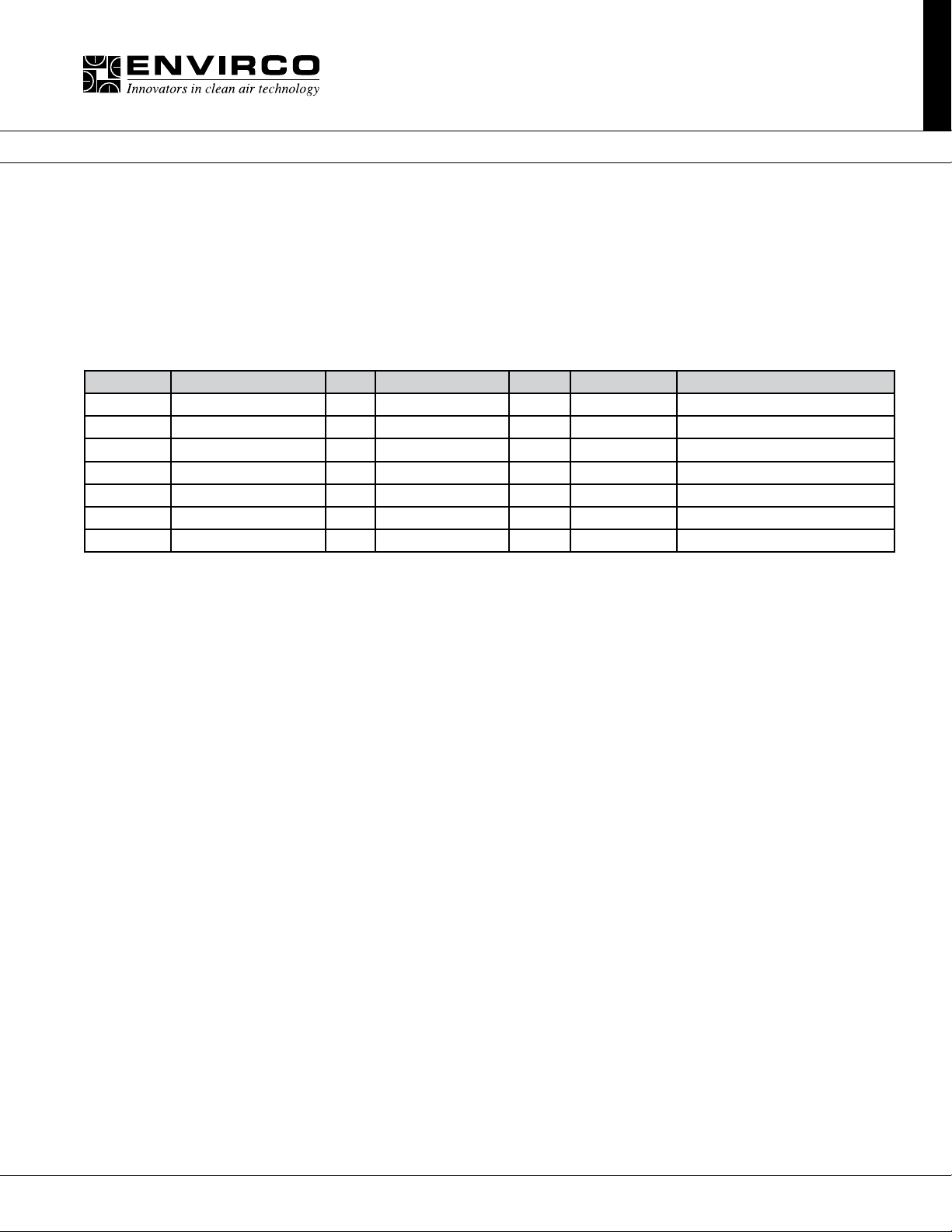
MODBUSRegisterSpecications:
Register Name R/W Values&Defaults Units Origin Comments
1 RUN/STOP RW 0,1 1 RAM power up from REG 14
2 DEMAND RW 0-100 % RAM power up from REG 10
6 SPEED R 0,5-2000 RPM LIVE
9 STATUS R see detail - LIVE
10 DEFAULT SPEED RW 0-100 50 EEPROM applies to network only
12 CURRENT SPEED R 0-100 - LIVE
14 DEFAULT RUN/STOP RW 0,1 1 EEPROM applies in network mode only
To reset non-volatile registers to factory default values, write 170 (AA hex) to Register 14, and then cycle power.
7Innovators in Clean Air Technology | www.envirco.com
Page 8

Clean air solutions built for you.
MOREINFORMATIONAVAILABLEATWWW.ENVIRCO.COM
Part #: 265888
Universal Control Card
Industrial
CleanroomProducts
®
» MAC 10
» MAC 10
» MAC 10 Original
» Ducted Ceiling Module:
DCM & RSR
» AC or DC Control Systems
LEDC
®
IQ™
Hospital&Healthcare
Hospital&Healthcare
®
» IsoClean
with Ultraviolet Light
» AirCeil
» Hospi-Gard® Room
Pressure Monitor
EnviramedicProducts
» HOR Horizontal Flow
Enclosure
» HCF Horizontal Flow
Surgery Room
and IsoClean
®
Pharmaceutical
Pharmaceutical&
MedicalDevice
» MAC 10™ and
Mac 10 IQ Rx™
» Unimodule M-2 Vertical
Unidirectional Flow
Workstation
» METD 100% Exhausted
Vertical Flow Workstation
» Unidirectional Downow
Module
Laboratory&Research
Laboratory&Research
» 100-Plus Horizontal or
Vertical Flow Clean Bench
» Unidirectional Flow
Horizontal Flow Bench (LF)
» TT Table Top Horizontal
Flow Clean Bench
» EnviraLab Sterility Module:
ESM
» NSF 49 Listed Biological
Safety Cabinet
» VOR Vertical Flow Surgery
Isolator
Envirco MAC 10 and VE5 are registered trademarks of Envirco, USA. Specications subject to modications or changes without notice. US patents 4,560,395 and 5,470,363. Other patents issued and pending in
foreign countries. Special thanks to Connect2Cleanrooms for cleanroom photography.
EnvircoUSA
101 McNeill Road | Sanford, NC 27330, USA
tel: 919.775.2201 | toll free: 800.884.0002 | fax:800.458.2379
www.envirco.com | email: [email protected]
Copyright ©2012 Envirco. All Rights Reserved.
EnvircoEuropeanSales
The Cavendish Centre, Winnall Close | Winchester, Hampshire; S023 OLB, UK
tel:+44(0)1962.840465 | fax:+44(0)1962.828619
www.trion.co.uk | email: [email protected]
AsianSalesandManufacturing
Building #1 | No.19 Xiangpu Road, Shenpu, SIP | Jiangsu Province, PRC 215021
Tel: +86.512.62967272 | Fax: +86.512.62967221
www.envirco.com | email: [email protected]
 Loading...