

Page 1
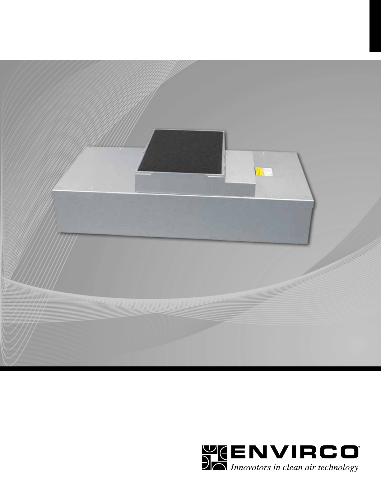
OPERATION & MAINTENANCE MANUAL
Envirco Technical Support: 800-884-0002
MAC 10® IQ
Fan Filter Unit
Standard, RSR, & RSRE Models
Page 2

MAC 10® IQ
Fan Filter Unit
Installation & Service Manual
Table of Contents
Critical Operations of the MAC 10® IQ .............................................................................. 3
Part numbers .................................................................................................................... 3
Warnings .......................................................................................................................... 4
Installation ........................................................................................................................ 5
Unit Control Box ............................................................................................................... 6
Universal Control Card Set Up ......................................................................................... 7
Troubleshooting ............................................................................................................... 12
Infrared Speed Control .................................................................................................... 13
Cleaning (foam) ............................................................................................................... 14
Service: Removal and Replacement of Standard Filters ................................................. 15
Service: Removal and Replacement of RSR/E Filters .................................................... 16
Service: Standard and RSR Motor Removal and Installation .......................................... 17
Service: RSRE Motor Removal and Installation .............................................................. 18
Technical Note: TN1004 Changing Motors in the Field ................................................... 19
Technical Note: TN1002 Design with VAV Boxes ............................................................ 21
MAC 10 IQ Wiring Diagrams ........................................................................................... 22
MAC 10 IQ Replacement Parts List................................................................................. 24
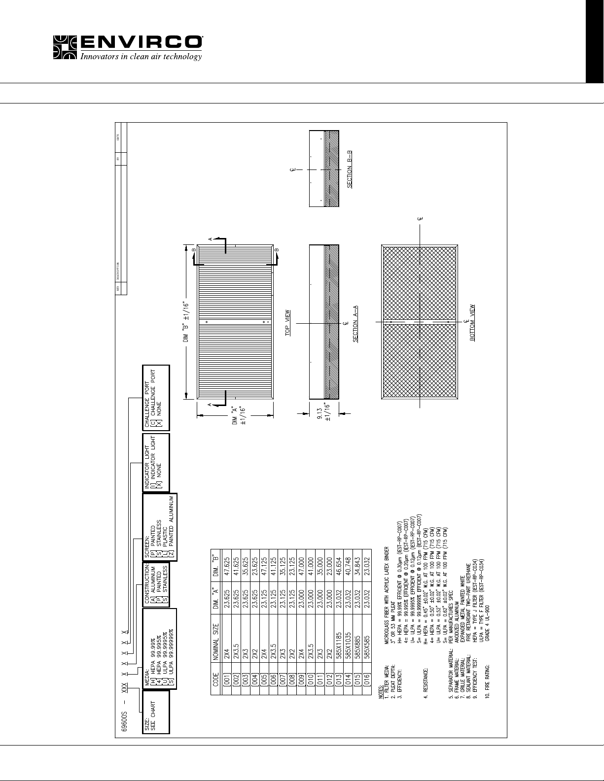
Drawing - MAC 10 IQ Standard Filter .............................................................................. 25
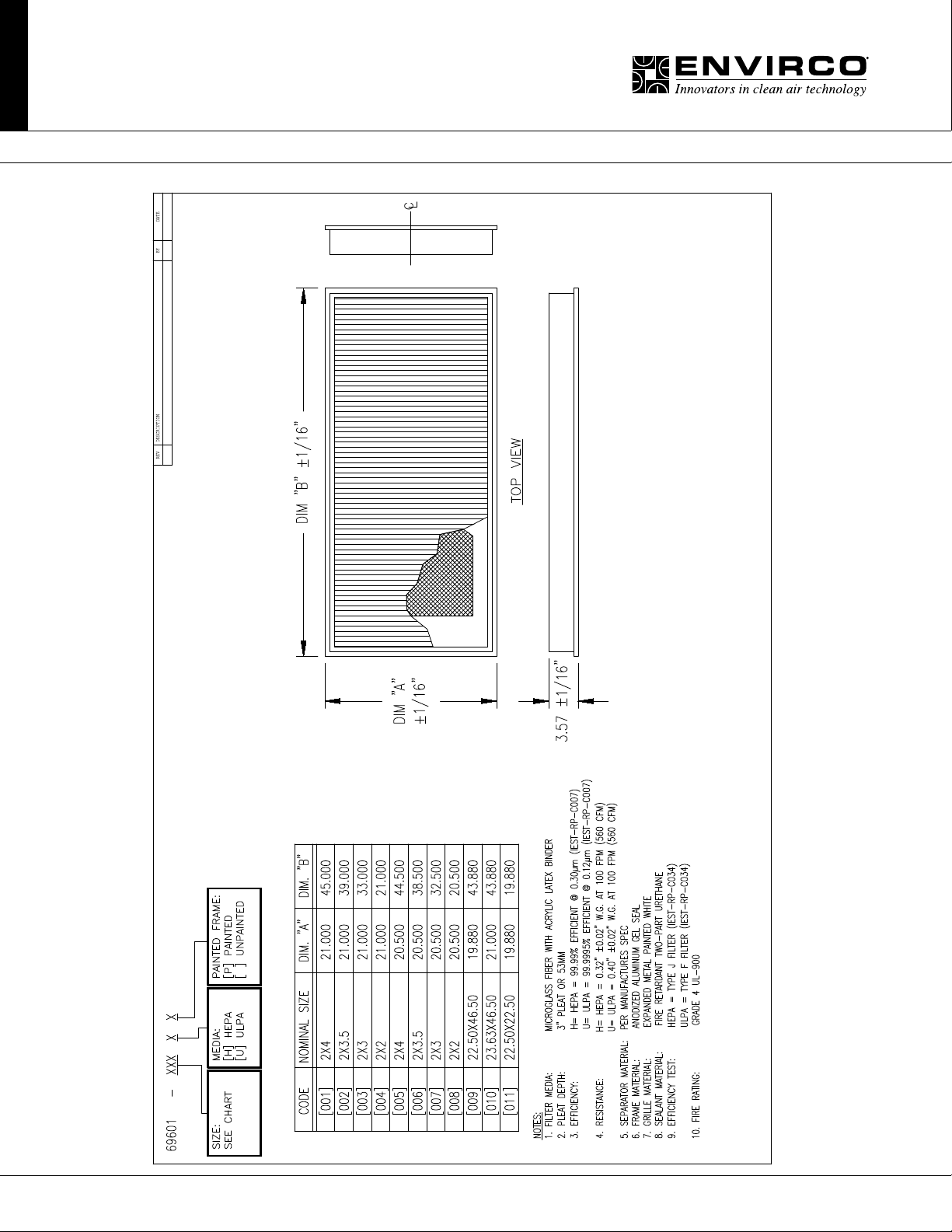
Drawing - MAC 10 IQ RSR Filter ..................................................................................... 26
Limited Warranty ............................................................................................................. 27
Testing ............................................................................................................................. 27
For MAC 10 4x4, please see manual form #267278.
For freight damage inquiries, call 800-884-0002 with model and job number available.
2 Innovators in Clean Air Technology | www.envirco.com | Operation & Maintenance
Page 3
MAC 10® IQ
Fan Filter Unit
Installation & Service Manual
■ Critical Operation Conditions of the MAC 10 IQ
1. Touching of the HEPA lter will damage it, voiding the warranty on the lter. The screen is only to protect against an
accidental ‘touch’ of the lter. Never place a hand or tool on the lter. Never lie lter face at down on a surface always
have lter on its side to protect from damage.
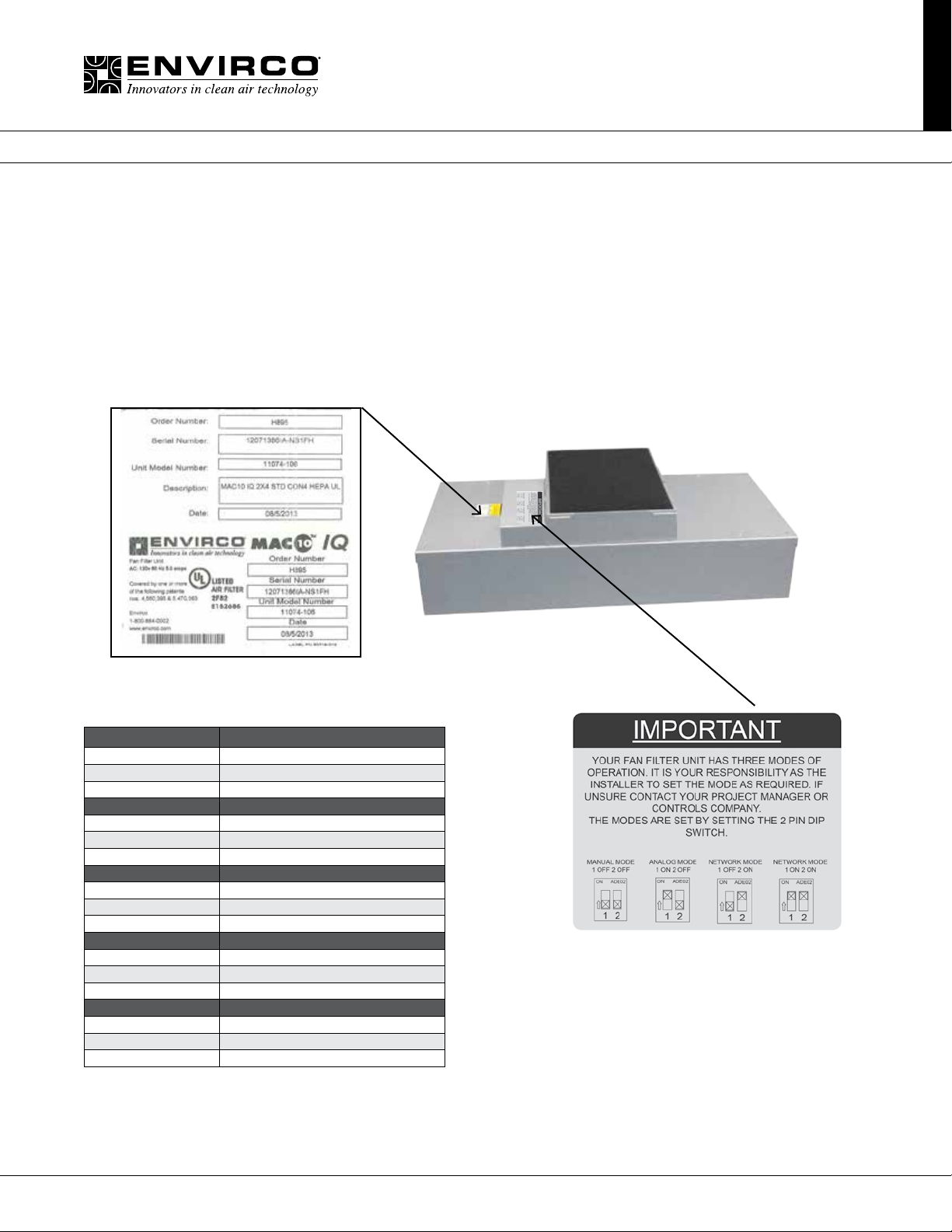
2. Prior to powering the unit, verify voltage on label and that the unit has been wired into the correct voltage. The serial
number label on the top of the Mac 10 IQ unit has the required voltage.
3. To insure you order the proper replacement parts or complete MAC 10 IQ unit, record the part number and serial number.
This information is located on the serial number label, located adjacent to the electrical box. If you can’t locate the Sales
Order Number, please contact Envirco for this information. Once obtained, record the information for reference.
■ Part Numbers Covered by this Manual
MAC 10 IQ Standard P/N
2x4 11074-XXX
2x3 11084-XXX
2x2 11083-XXX
MAC 10 IQ RSR P/N
2x4 11089-XXX
2x3 11087-XXX
2x2 11086-XXX
MAC 10 IQ RSRE P/N
2x4 11089-ZXXX
2x3 11087-XXX
2x2 11083-ZXXX
MAC 10 IQ RX RSR P/N
2x4 11124-XXX
2x3 TBA
2x2 11127-XXX
MAC 10 IQ RX RSRE P/N
2x4 11124-ZXXX
2x3 TBA
2x2 11127-ZXXX
Units come set in manual mode from
the factory. Please review installation
requirements and set up with your end user
(See page 8 for complete set up instructions).
3Innovators in Clean Air Technology | www.envirco.com | Operation & Maintenance
Page 4

MAC 10® IQ
Fan Filter Unit
Installation & Service Manual
■ Warning
TO REDUCE THE RISK OF FIRE, ELECTRICAL SHOCK, OR INJURY TO PERSONS, OBSERVE THE FOLLOWING:
A. Installation work and electrical wiring must be done by qualied person(s) in accordance with all applicable codes and
standards, including re-rated construction.
B. When cutting or drilling into wall or ceiling, do not damage electrical wiring and other hidden utilities.
C. If this unit is to be installed over an area using liquid, such as water or chemical cleaning solutions, it must be marked as
appropriate for the application.
D. Use this unit only in the manner intended by the manufacturer. If you have any questions, contact the manufacturer.
E. Before servicing or cleaning the unit, switch power off at unit service panel and lock service panel to prevent power from
being switched on accidentally.
ENVIRCO USA
101 McNeill Road
Sanford, NC 27330
Tel: (919) 775-2201
Tel: (800) 884-0002
Fax: (800) 458-2379
Email: [email protected]
ASIAN SALES
Building #1
200 Middle Suhong Road
Suzhou, Jiangsu
PRC 215021
Tel: (86) 512 6258 0031
Fax:(86) 512 6258 7180
Email: [email protected]
Europe, Middle East & Africa (EMEA)
TRION Div of Ruskin Air Management Ltd
European Operations
The Cavendish Center Winnall Close
Winchester Hampshire
S023 OLB, UK
www.envirco-emea.com
Tel: +44 (0) 1962 840465
Fax: +44 (0) 1962 828619
Email: r[email protected]
4 Innovators in Clean Air Technology | www.envirco.com | Operation & Maintenance
Page 5
MAC 10® IQ
Fan Filter Unit
Installation & Service Manual
■ Installation
Note: The MAC 10 IQ Fan Filter Unit is completely assembled at the factory with the exception of the optional ¼” (0.64 cm)-20
eyebolts that are used when hanging the unit from an engineered design support system and installation of the HEPA/ULPA
lters (eyebolts not included and need to be ordered separately, p/n 222449-001).
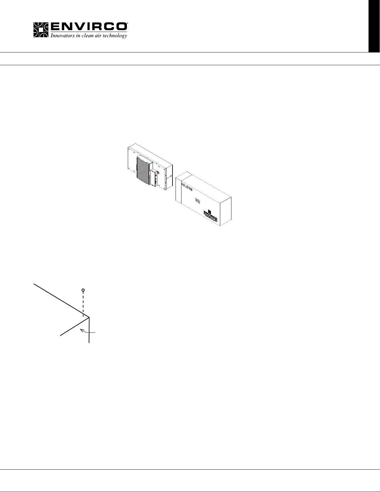
Step 1. Carefully remove the unit from the shipping carton and inspect for any damage that may have occurred during
transportation (See Figure 1).
Recommendation:
Review mode settings
at this time as specied
for installation
(see page 7 for controls).
Figure 1: Unboxing
Step 2. If using rigidly supported grid (usually 2” (50 mm) or wider), raise unit through ceiling and lower onto the gasketed grid.
If using a exible grid (typically supported with wires), the unit must be secured to an engineered design support system with
s-hooks and chain. Screw the four eyebolts into the nutserts on the lid assembly before lifting into an overhead position (see
Figure 2). Note: Conrm fan dimensions to match T-grid dimensions.
EYEBOLT
FAN FILTER
UNIT
Note: When ordering RSR and RSRE
units, the HEPA lters may be shipped
separately to be installed into units after
the fan box has been installed.
Figure 2: Hanger Supports
Step 2.1. If using a support grid, continue...
Step 3. Raise the unit and secure it into place using the chosen support system method suspended from a structural support
bracing.
Step 4. Have an electrician wire the unit to the appropriate voltage, according to the wiring diagram (page 17), and all national
and local electrical codes. All units are equipped with a three position terminal block for eld connection. Verify correct single-
phase power, before energizing units.
Step 5. Turn on the power using the two position rocker switch (ON/OFF) located on the electrical box. For RSR/E units, let
the unit run for a few hours to purge off particulate (if lters are shipped loose) that may be adhered to the inside of the unit
before installing the lters. Do not run fan at full speed as this may cause overload condition.
Note: Your fan lter may have been shipped separately. Controls have been shipped separately.
5Innovators in Clean Air Technology | www.envirco.com | Operation & Maintenance
Page 6
MAC 10® IQ
Fan Filter Unit
Installation & Service Manual
■ Unit Control Box
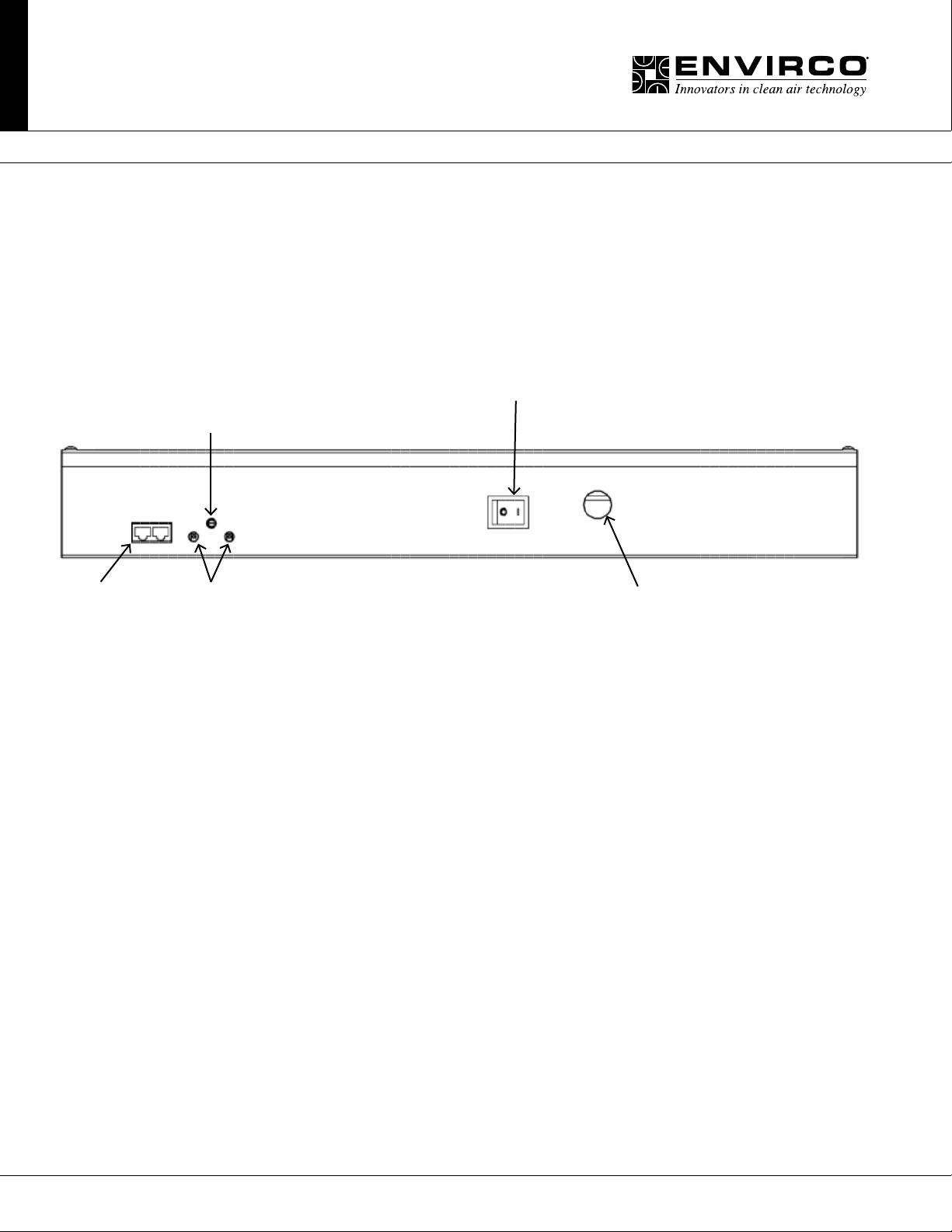
2.1. ON/OFF Switch - Speed/Airow Adjustment
All MAC 10 IQ units are equipped with a two-position rocker switch (ON/OFF), which is located on the side of the electrical box,
on top of the unit. All units are furnished with a Universal Control Card to enable adjustment of airow or set to your means of
communication. (see Page 7 for CON4 Universal Card Card Set Up).
Manual
Speed
Potentiometer
CAT 5e
Network Cables
(RJ45 Connector)
Note: The CAT5e/RJ45 network ports are non-directional (i.e. in or out). Be sure to examine your cabling to insure
that there is no cross-over wired cables.
RPM
Test Probe
Jack Comm
Figure 3 : Electrical Box Face
ON/OFF
Switch
Electrical Knock Out
6 Innovators in Clean Air Technology | www.envirco.com | Operation & Maintenance
Page 7
MAC 10® IQ
INCOMING POWER 24VAC
EXTERNAL
Fan Filter Unit
Installation & Service Manual
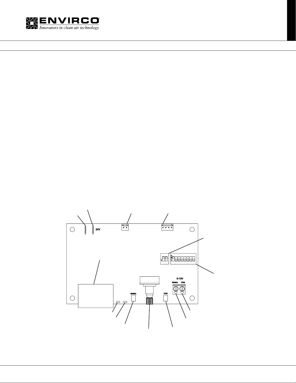
■ CON4 Universal Control Card Set Up (Model ENV1028)
CON4 UNIVERSAL CONTROL CARD - PRODUCT OVERVIEW
Envirco’s ENV1028 Universal Control Card provides MODBUS network and analog control capabilities to an Envirco Fan Filter Unit
equipped with an electrically commutated motor. Three different control modes provide installation versatility by allowing the FFU to
be controlled via MODBUS RTU network, analog 0-10 VDC control signal, or by adjusting the onboard potentiometer. The ENV1028
Universal Control Card is fully compatible with all of Envirco’s plug & play System Control Consoles using MODBUS RTU. Additional
details of the controls modes are provided on page 8.
FEATURES
• Networkable Via MODBUS RTU
• 0-10 VDC Analog Control
• Manual Control Via Onboard Potentiometer
• Simple Connections
• RJ45 For Networking Connection
• Screw Terminals For Analog Control
• Test Probe Jacks For DC mV Signal Output Of The Following...
• RPM
• Motor Control Set Point
• LED Diagnostics
• Support for external LED (10mA) remote status notication via 2 Pin MTA connector
• Onboard green LED for Board Status notication
• Onboard red LED for Network Trafc
• Powered from Network or Local Supply
COMMON
DUAL RJ-45 JACKS FOR CAT 5 CABLE
RED LED FOR NET ACTIVITY
GREEN LED FOR SYSTEM/RPM STATUS
RPM TEST PROBE JACK "SIGNAL"
Note: CON4 Univeral Control Card is also referenced as model # ENV1028.
LED CONNECTOR
MANUAL SPEED POT
MOTOR CONTROL HARNESS CONECTOR
CONTROL MODE DIP SWITCH
S1
1 1 2 3 4 5 6 7 82
RPM TEST PROBE JACK "COM"
S2
NETWORKING
ADDRESSING DIP SWITCH
ANALOG INPUT "COM"
ANALOG INPUT "SIGNAL"
7Innovators in Clean Air Technology | www.envirco.com | Operation & Maintenance
Page 8
MAC 10® IQ
Fan Filter Unit
Installation & Service Manual
CONTROL MODES
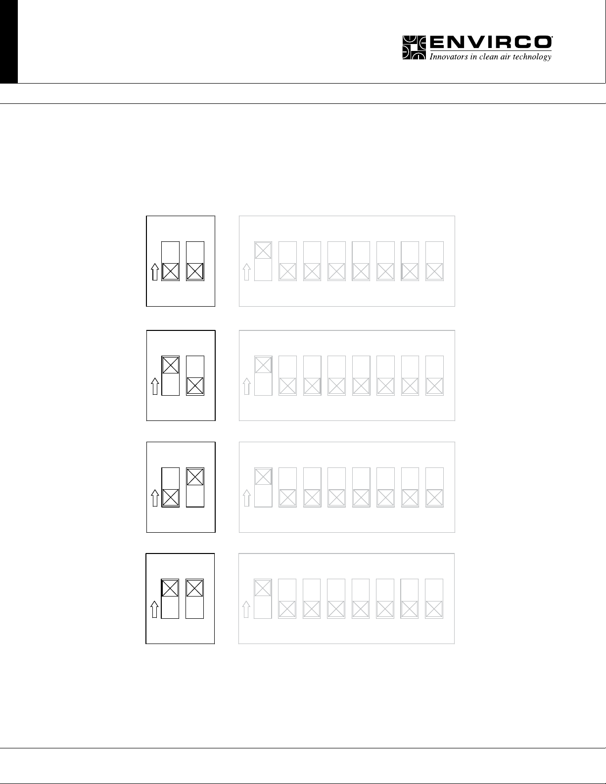
The ENV1028 operates in one of three selectable modes. The Mode is selected using DIP Switch S1.
• MANUAL control, on-board potentiometer
• ANALOG control, Remote 0-10 VDC
• NETWORK control, MODBUS RTU
Manual Mode = 1 OFF 2 OFF
ON ADE02
1 3 4 5 6 7 8
O
N
1
2
Analog Mode = 1 ON 2 OFF
ON ADE02
1 3 4 5 6 7 8
O
N
1
2
Network Mode = 1 OFF 2 ON
ON ADE02
1 3 4 5 6 7 8
O
N
2
2
2
1
2
Network Mode = 1 ON 2 ON
ON ADE02
1
2
Note: Network mode can be congured using either DIP switch setting shown above.
DIP switch pictorials are for reference and may be labeled differently by the manufacturer.
8 Innovators in Clean Air Technology | www.envirco.com | Operation & Maintenance
1 3 4 5 6 7 8
2
O
N
Page 9
MAC 10® IQ
Fan Filter Unit
Installation & Service Manual
Manual Control Mode:
In Manual control mode, the motor speed is set using the onboard potentiometer. Onboard potentiometer rotation is clockwise to
increase the motor output.
Analog Control Mode:
In ANALOG control mode, the motor output is set using an external 0-10 VDC demand signal.
Network Control Mode:
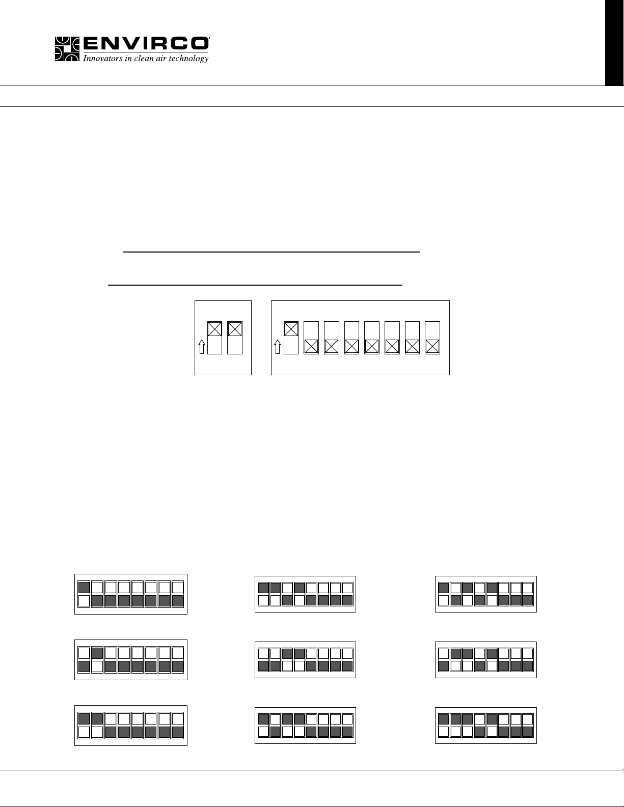
In NETWORK control mode, the motor output is set using MODBUS Register 2. Motor output is specied as a value from 0 to 100
representing a percentage of motor torque output. Each ENV1028 in a MODBUS network must be set to a unique address. The
address value is set in binary format using the eight DIP switches of switch bank (S2). A maximum of 200 ENV1028 devices is
recommended per local area network(LAN). If an Envirco ACC Control Console is the MODBUS master, then addresses should be
assigned within the address range supported by the Control Console. Address zero should not be used as it is reserved for global
commands. Address switch settings are only checked by the ENV1028 at power-up. Power must be cycled (OFF/ON) before any
changes take effect.
ON ADE02
1 3 4 5 6 7 8
2
O
N
1
2
Control Mode
DIP Switches
Addess DIP Switches
S2
S1
Note: Network mode can be congured using either DIP switch setting shown above. DIP switch pictorials are for
reference and may be labeled differently by the manufacturer.
Registers relevant to this mode (see chart on page 11):
• Register 1 “Start/Stop” (R/W)
– To enable motor, write a value of 1; To disable motor, write a value of 0
• Register 2 “Motor Set Speed” (R/W)
– Motor Target speed value. Values may be written from 0 to 100
• Register 6 “RPM” (R)
– Motor RPM. Read from the motor
• Register 12 “Actual Motor Speed Instruction” (R)
– Speed control signal applied to the motor by the ENV1028.
(R/W) = Read/Write, (R) = Read Only
ON DIP
12345678
ON DIP
1
ON
12345678
ON
DIP
DIP
11
ON
12345678
ON
DIP
21
DIP
12345678
ON DIP
12345678
2
3
12345678
ON
12345678
Example of binary S2 switch settings
DIP
12
13
12345678
ON
12345678
DIP
22
23
9Innovators in Clean Air Technology | www.envirco.com | Operation & Maintenance
Page 10
MAC 10® IQ
Fan Filter Unit
Installation & Service Manual
ELECTRICAL SPECIFICATIONS
Control and Interface Signals:
1. External Speed 0-10V Input
• Input impedance 20k Ohms.
• MIN ON-to-OFF threshold: 190mV
• MAX OFF-to-ON threshold: 240mV
• ON (~215mV) to 9.89V linearly scales 1 to 99% speed.
• 9.89V or more deadbands to 100% speed.
2. External LED Output
• 10mA regulated
• LED forward voltages up to 5V
3. RPM Signal
• Signal Value: mVDC = RPM
• Ex: 900mV = 900RPM
• RPM Output Range: ~ 0, 5 to 2000 RPM (0, 5mV to 2000 mV DC)
• RPM Output Resolution: 5RPM (Zero, 400 steps from 5 to 2000 RPM inclusive)
Electrical and Environmental Specications:
Specication Min Typical Max Units
Input Voltage 22 24 42 VAC
Supply Frequency 50 50/60 60 Hz
Input Power Consumption na na 0.5 VA
Ambient Operating Temperature 0 25 50 C
Test Probe JacksPoints:
The test probe jacks may be used to measure the motor rpm or the PWM signal that is being output to the motor.
• In Manual or Analog Control Mode with a S2 address setting of 1 or greater, the test probe jacks output 0-2000 mVDC representing motor RPM. By changing the address S2 switch to 0, the test probe jacks will output 0-1000 mVDC representing
0-100% demand signal to the motor. The address may be changed without interrupting power to the control card.
• In Network Control Mode, 0-2000 mVDC always represents RPM.
LED Indicators:
• Onboard Status LED:
The Onboard Status LED is software controlled by the unit microcontroller. The Status LED is solid ON when RPM reported by
the motor is greater than zero and OFF when RPM reported by the motor is zero.
• External Status LED:
Support for an external Status LED (10mA current-controlled driver), via a 2-pin MTA connector, for remote system status notication. The external Status LED operates in the same manner as the Onboard Status LED.
• Onboard Net LED:
The Onboard Net LED is driven directly by the receive data signal. The NET LED shows all network trafc on a 2-wire network.
The NET LED is intended to conrm low-level network connectivity, independent of microcontroller or rmware functionality. If
A/B network wires are swapped, the NET LED will be normally on, providing quick diagnostics of this common condition.
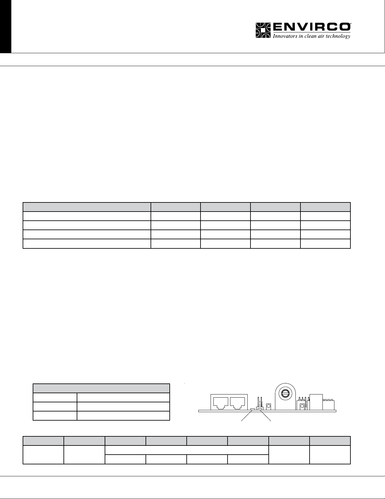
Net LED Status Denition
LED OFF Power Lost or No Communications
LED Flickering Network Data Trafc In Progress
LED ON A/B network wires are swapped
RJ45 Network Cable Connections:
1 2 3 4 5 6 7 8
Bus Power
Pass Through
0V (GND) RS-485 0V (GND) Bus Power
+ NC NC -
Red Network LED Green Status LED
Pass Through
10 Innovators in Clean Air Technology | www.envirco.com | Operation & Maintenance
Page 11
MAC 10® IQ
Fan Filter Unit
Installation & Service Manual
COMMUNICATION SPECIFICATIONS
Overview:
• MODBUS RTU protocol over RS485 (serial)
• 9600 baud rate, word length is 8, parity is none(n), stop bits=1
• 255 unique address values selectable by S2 switch settings
(recommended network node capacity 200 nodes)
• Slew rate limited transceivers for improved network performance MODBUS Register Summary Table
• DO NOT USE CROSSOVER CABLES. THIS MAY DAMAGE THE CONTROL CARD OR RENDER IT NON-OPERATIONAL.
MODBUS Register Specications:
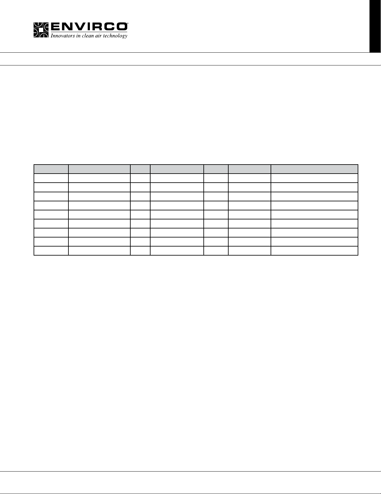
Register Name R/W Values & Defaults Units Origin Comments
1 RUN/STOP RW 0,1 1 RAM power up from REG 14
2 DEMAND RW 0-100 % RAM power up from REG 10
6 SPEED R 0,5-2000 RPM LIVE
7 ANA1 R 0-1000 - LIVE Onboard Pot 0-1000=0-100%
9 STATUS R see detail - LIVE
10 DEFAULT SPEED RW 0-100 50 EEPROM applies to network only
12 CURRENT SPEED R 0-100 - LIVE
14 DEFAULT RUN/STOP RW 0,1 1 EEPROM applies in network mode only
24 ANA2 R 0-1000 - LIVE 0-10V input 0-1000=0-10VDC
To reset non-volatile registers to factory default values, write 170 (AA hex) to Register 14, and then cycle power.
Note: Register 24 may be read in network mode to determine the value of 0-10VDC signal that may be connected.
For example, a pressure transducer may be connected to indicate unit interal static pressure.
11Innovators in Clean Air Technology | www.envirco.com | Operation & Maintenance
Page 12
MAC 10® IQ
Fan Filter Unit
Installation & Service Manual
■ Troubleshooting
Mode Choice:
Verify mode setting choice to DIP switch S1 (Control Mode), which is manual mode and then retry.
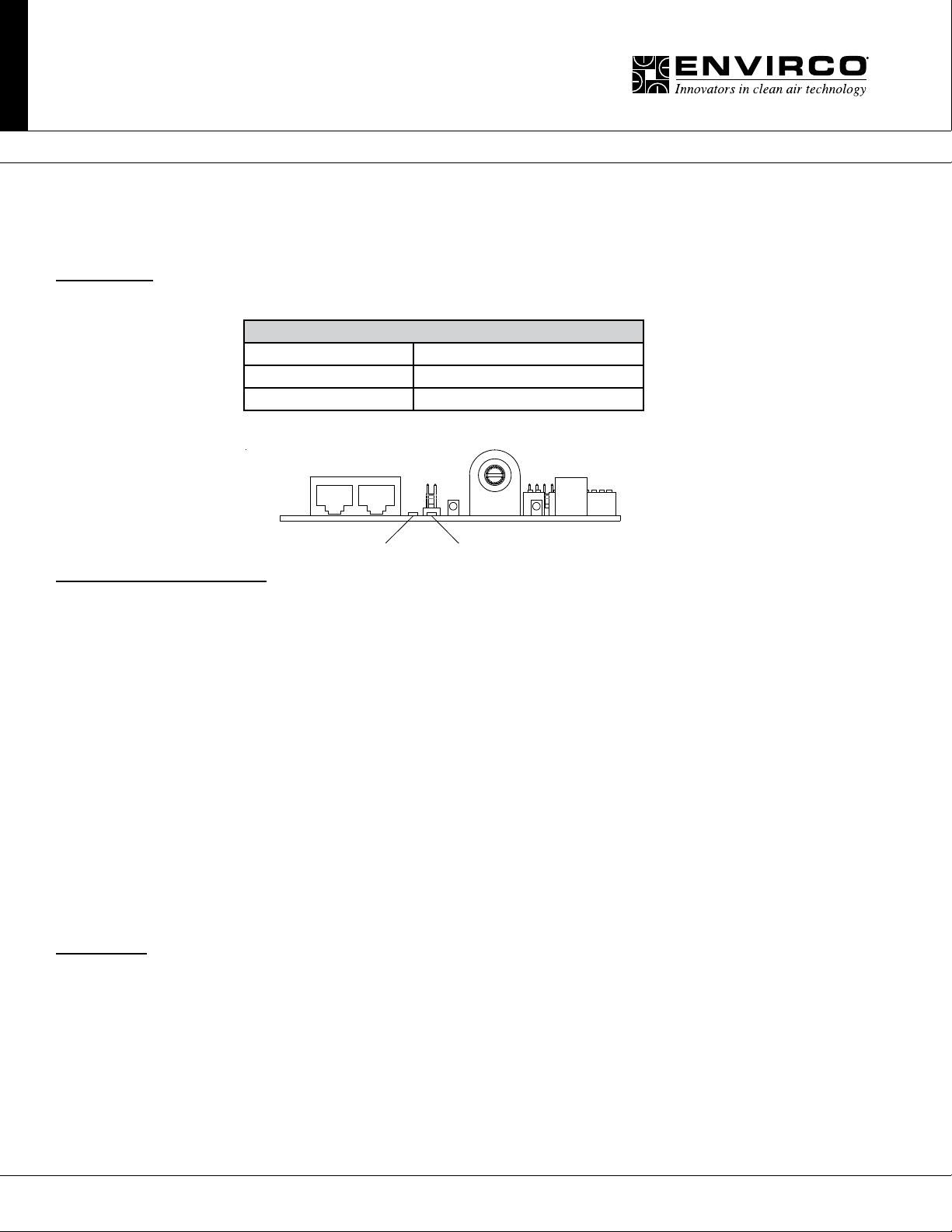
Net LED Status Denition
Green LED OFF Power Lost or No Communications
Green LED Flickering Network Data Trafc In Progress
Green LED ON A/B network wires are swapped
Red Network LED Green Status LED
Motor Issues in Manual Mode:
(If you are in a network or analog mode, contact your controls contractor for troubleshooting assistance; if you continue to
need assistance, contact the factory.)
Unit is not adjustable:
Step 1. Verify that rotation of the manual speed potentiometer does not change the RPM. If rotating does nothing, remove
the electrical box cover, then remove the 4-pin motor connector from the control board and reinstall 180 degrees rotated.
Also insure that the 4-pin connection wires are pushed down securely onto connector pins. Again adjust the knob to verify
proper fan operation. Note: The 4 pin connector is on the 1/8” white cable from motor.
Low Air Velocity:
Step 1. Check to be sure that the manual speed potentiometer is set correctly.
Step 2. Check incoming power supply for proper voltage (120,208-240,277/24).
Step 3. Examine the HEPA lter.
High Air Velocity:
Step 1. Check to be sure that the air ow settings are correct.
Filter Issues:
Non-Laminar Flow and/or Excessive Contamination:
Step 1. Insure that no large obstructions are upstream of airow pattern.
Step 2. Determine that no other air-moving devices are operating in or around clean room which disrupt room’s
airow pattern.
Step 3. Check air velocity and if low, conduct the “Low Air Velocity” procedure outlined above.
If failure continues, contact Envirco Technical Support at 800-884-0002.
12 Innovators in Clean Air Technology | www.envirco.com | Operation & Maintenance
Page 13
MAC 10® IQ
Fan Filter Unit
Installation & Service Manual
Infrared Speed Control (Optional)
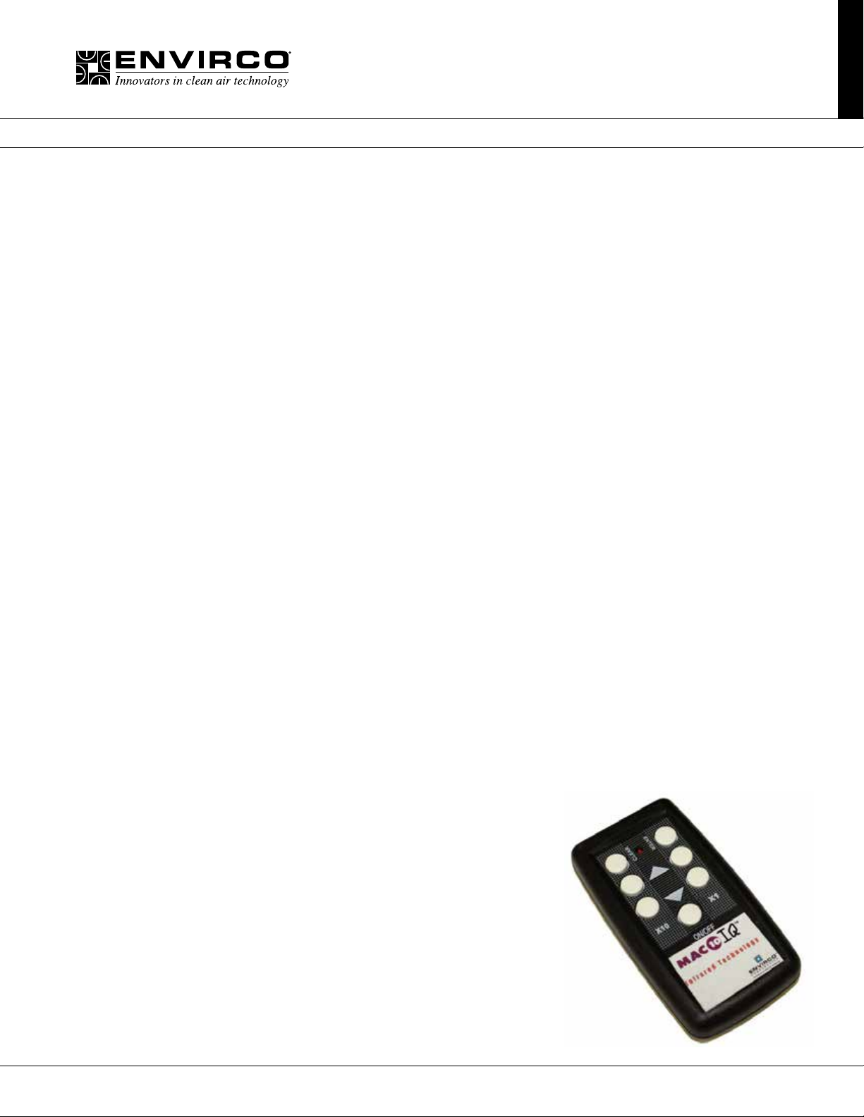
The Flow-Set is a handheld infrared remote control congured to adjust the Envirco Mac 10 IQ unit.
An EVO/ECM-IRC control sends the motors a FLOW INDEX and a GO signal. The motor sends back a status signal that is connected
to a red lamp. The control includes an infrared remote receiver.
The Flow-Set handheld remote sends infrared remote commands to the EVO/ECM-IRC control, allowing remote adjustment of the
Motor. (See Figure 10). Using the Flow-Set, you can turn the motor on/off, adjust the ow index from 1-100 and read the current
settings.
Point the Flow-Set at the Flow-Set target (red lamp if the motor is on) on the equipment. Operate the on/off button or any of the four
↑↓ buttons. The green lamp near the Flow-Set target lights, indicating you are in an adjustment session. Continue to operate the
on/off button or any of the four ↑↓ buttons to achieve the desired settings.
Press the Enter button to save your new settings and exit the adjustment session. Press the Clear button to delete your new settings,
revert to the IQ settings and exit the adjustment session. If you enter an adjustment session and do not make any adjustments for 15
minutes, the adjustment session automatically clears.
Use the Clear button to read the current settings. Point the Flow-Set at the Flow-Set target and press the Clear button. A green lamp
begins to ash indicating the signal was received. The ash sequence indicates the current ow index. The sequence occurs in two
sets. The tens (1st) set uses long ashes to indicate the tens digit. The units (2nd) set uses short ashes to indicate the units digit. An
extra long ash in the tens set or the units set indicates the value of the corresponding digit is zero.
• A ow index of 24 ashes two longs, then 4 shorts.
• A ow index of 89 ashes 8 longs, then 9 shorts.
• A ow index of 30 ashes 3 longs, then an extra long.
• A ow index of 04 ashes an extra long, then 4 short.
• A ow index of 100 ashes 10 longs, then an extra long.
Use the On/Off button to turn the motor on or off. Point the Flow-Set at the Flow-Set target on the equipment and press the on/off
button. If you press Enter while the motor is off, the motor stays off, even through a power on/off cycle.
Adjust the ow index using the ↑↓ buttons. The ↑↓ button pair on the left adjusts the index ↑↓ 10. The ↑↓ button pair on the right adjusts
the ow index ↑↓1. Using the ↑↓10 pair, you can quickly move the index up and down. Using the ↑↓1 pair, you can precisely set the
index to achieve the desired ow. During an adjustment session, the green lamp blinks each time you make a valid entry. If the ow
index is already 100, and you try to increase the ow index, the green lamp does not blink, and the increase does not occur. If the
ow index is at 91 and you press the ↑↓10 buttons, the green lamp does not blink and the increase does not occur because your entry
would take the index above 100. When the ow index is greater than 90, use the ↑↓1 button to increase the index. The ↑↓1 and ↑↓10
keys respond in a like manner when you try to set the ow index below 1. (Zero is not a valid ow index).
Batteries
Two AA batteries power the EVO/IRC-Handheld Controller. (See Figure 10). Remove
the sliding door on the back of the unit to expose the battery compartment. Remove
the old batteries. Insert the new batteries in the position indicated by the battery
pictures
molded into the bottom of the battery compartment. The battery spring clips are
difcult, so you may need to use a small screwdriver to “shoehorn” the batteries into
place.
For maximum battery life, store the EVO/IRC- Handheld Controller so the buttons
are not pressed. While current drain is minimum when the unit is not sending infrared
signals, some battery current is drawn to sense the pressed key.
13Innovators in Clean Air Technology | www.envirco.com | Operation & Maintenance
Page 14
MAC 10® IQ
Fan Filter Unit
Installation & Service Manual
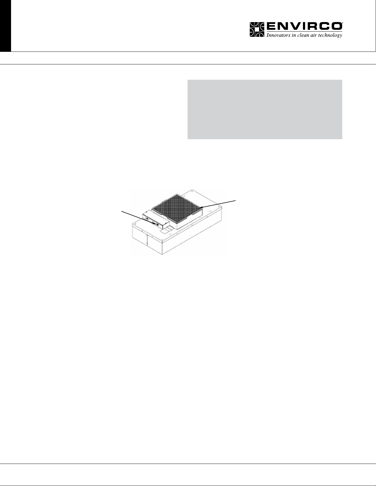
■ Cleaning the IQ Pre-filter (foam)
Tools Required: None.
Note: To keep the lter in top operating condition, washing
the foam prelter is recommended every three to six months.
Step 1. To gain access to the prelter, remove the ceiling
panel next to the unit, if applicable.
Step 2. Switch the ON-OFF switch to the off position.
Step 3. Remove the 16”x23” prelter from the snap-in frame. (See Figure)
Step 4. Clean the prelter by hand washing in water with a mild detergent or by using a vacuum cleaner. Allow prelter to
dry completely before replacing.
Step 5. Reassemble by reversing the above steps.
ON/OFF Switch
DISCONNECT THE UNIT FROM THE ELECTRICAL
POWER SOURCE BEFORE ATTEMPTING
WARNING
ANY SERVICE
16” x 23”
(foam prelter)
14 Innovators in Clean Air Technology | www.envirco.com | Operation & Maintenance
Page 15
MAC 10® IQ
Fan Filter Unit
Installation & Service Manual
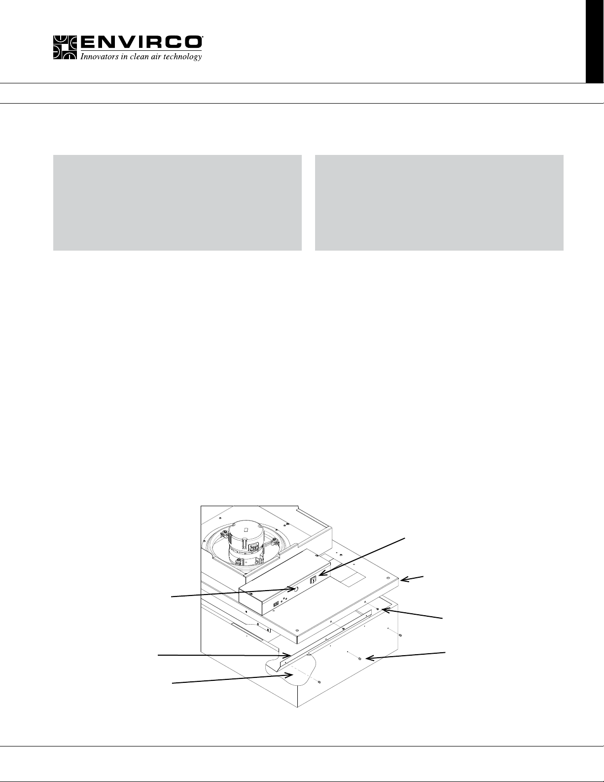
■ Service: Removal and Replacement of Standard HEPA/ULPA Filters
WARNING
WARNING
DISCONNECT THE UNIT FROM THE ELECTRICAL
POWER SOURCE BEFORE ATTEMPTING
ANY SERVICE
Note: All lters should be visually inspected for freight damage before installation. It is necessary to use two workers when
removing the lter and for installation to avoid twisting or separation of the media seals. Handle the lter only by the frame
and never place anything on the upstream lter side of the lter. Additionally, it is important to keep the lter level to prevent
any shearing force on the media itself.
For Standard Filters:
Tools Required: Phillips Head Driver, Battery Operated Drill with 5/32 drill bit, Rivet Hand Tool, Ø5/32 aluminum rivet grip
range .126-.187
THE STANDARD FILTER IS PROTECTED WITH AN
EXPANDED METAL FACE SCREEN. THIS IS
NEVER TO BE USED TO HANDLE THE FILTER.
IT IS ONLY FOR PROTECTION AGAINST AN
ACCIDENTAL TOUCH OF THE FILTER.
ONLY HANDLE THE FILTER BY THE FRAME.
Step 1. Remove unit from ceiling.
Step 2. Remove the 10 screws holding the HEPA/ULPA lter to the lid assembly.
Step 3. Lift the lid assembly off the HEPA/ULPA lter (see Figure). Remove Filter deectors using 5/32 drill bit. Keep lter
deectors to install in new lter. Discard the used lter as per requirements of the applicable regulations. Carefully install the
lter deectors into the new lter using the 5/32 rivets. Do not touch or place the lter deectors on the HEPA/ULPA media
pack. This could cause tears in the lter pack.
Step 4. Before replacing with the new lter, carefully inspect the new lter for any visible damage. Also inspect the gasket
and the T-Bar to insure a tight seal. Replace if necessary.
Step 5. To replace a lter, raise the lter and rotate into position in the ceiling grid (with power off) , then lower the plenum
housing into place. Reconnect wiring and hardware from previous steps that have been removed.
Step 6. Restore power and verify proper operation of FFU.
On/Off Switch
Lid Assembly
Electrical Knock Out
#8 Screws (10x)
Ø5/32 Rivet (6x)Filter Deflector
HEPA/ULPA Filter
Standard Filter Change
15Innovators in Clean Air Technology | www.envirco.com | Operation & Maintenance
Page 16
MAC 10® IQ
Fan Filter Unit
Installation & Service Manual
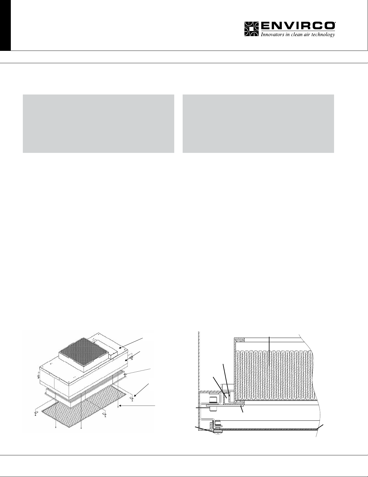
■ Service: Removal and Replacement of RSR/E Filters
WARNING
WARNING
DISCONNECT THE UNIT FROM THE ELECTRICAL
POWER SOURCE BEFORE ATTEMPTING
ANY SERVICE
Note: All lters should be visually inspected for freight damage before installation. It is necessary to use two workers when
removing the lter and for installation to avoid twisting or separation of the media seals. Handle the lter only by the frame
and never place anything on the upstream lter side of the lter. Additionally, it is important to keep the lter level to prevent
any shearing force on the media itself.
For RSR/E Filters:
Tools Required: Phillips Head Driver, Battery Operated Drill, 3/16” hex head ball driver (2ea)
Step 1. With the power off, remove the diffuser screen by removing the 6 each 10-32x1/2 screws, then carefully place in a
safe location.
Step 2. Loosen the six 1/4x12 socket head screws far enough to rotate the eight lter clips 90°. The lter may be loose
enough to drop during this operation. If not, slowly pull the lter away from the knife-edge seal, taking care not to touch the
lter face during this operation. It is important to pull the lter slowly away from the seal, so that the gel remains in the lter
gel track.
Step 3. Carefully clean plenum assembly knife edge surface of residual gel material.
Step 4. Inspect lter for visible damage, if damaged set aside for replacement or repair.
Step 5. Inspect the gel seal, if reinstalling the removed lter. Determine if the gel has lost its ability to seal (i.e. the gel should
reform to cover the track without voids or openings), if so repair the gel material or consider replacement of lter.
Step 6. Place the lter evenly against the lter-sealing surface of the RSR unit. Reposition lter clips and screws. The
clips should be rotated and angled into place. It is recommended that four workers work on each corner of the lter
simultaneously, holding the lter seated into the track. Hand tighten clips from opposite corners evenly until all clamps are
tightened.
Step 7. Reinstall diffuser screen by hand-tightening the screws.
Step 8. Determine if recertication or testing of replacement is required.
Step 9: Restore power to FFU and verify proper operation of FFU.
THE STANDARD FILTER IS PROTECTED WITH AN
EXPANDED METAL FACE SCREEN. THIS IS
NEVER TO BE USED TO HANDLE THE FILTER.
IT IS ONLY FOR PROTECTION AGAINST AN
ACCIDENTAL TOUCH OF THE FILTER.
ONLY HANDLE THE FILTER BY THE FRAME.
Fan Filter Unit
2-Piece Welded
Plenum Housing
Filter
Filter Clip and
Screw (typ 6)
Diffuser Screen
Screws (typ 6)
¼ -20
Cap
Screw
10-32
PHP
Screws
Knife- Edge
Seal
Gel Track
Filter Clip
Filter
Diffuser
Screen
RSR/E Filter Change RSR/E Sheet Metal Filter Replacement
16 Innovators in Clean Air Technology | www.envirco.com | Operation & Maintenance
Page 17
Installation & Service Manual
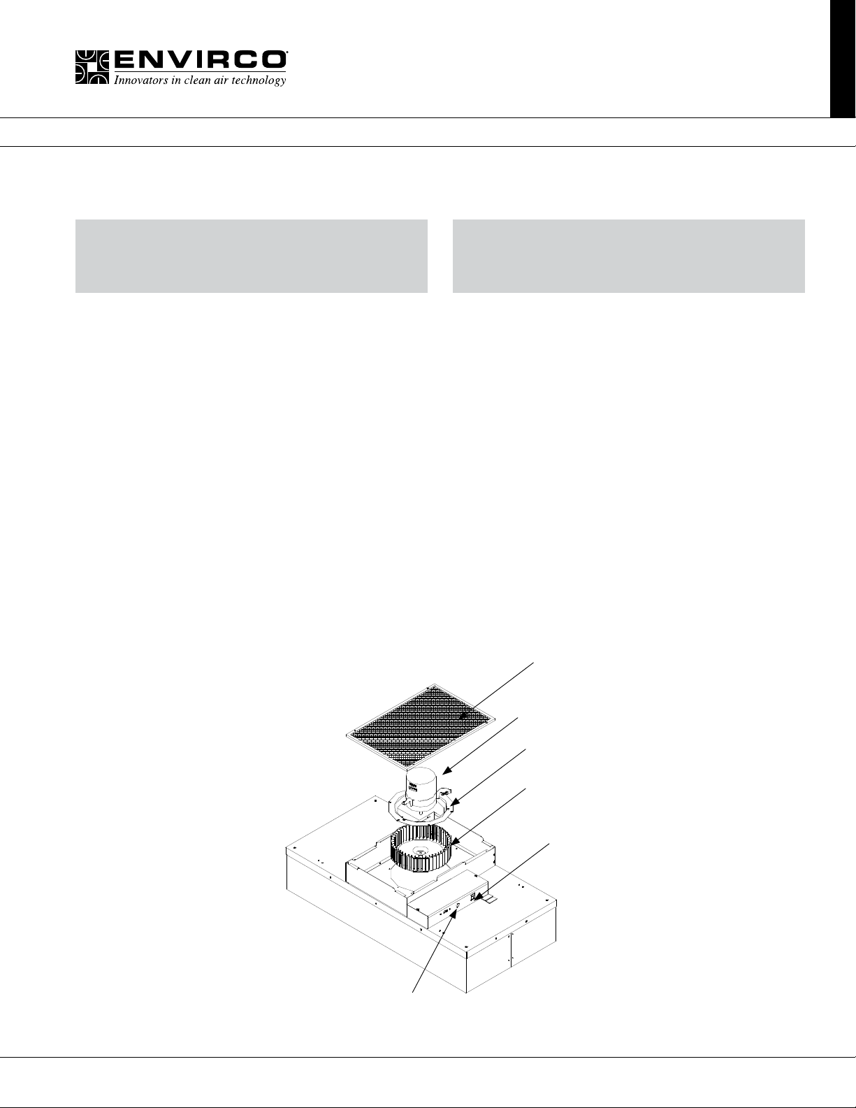
Venturi Ring
■ Service: Standard and RSR Motor Removal and Installation
MAC 10® IQ
Fan Filter Unit
WARNING
DISCONNECT THE UNIT FROM THE ELECTRICAL
POWER SOURCE BEFORE ATTEMPTING
ANY SERVICE
ELECTRICAL SERVICE SHOULD ONLY
BE PERFORMED BY A LICENSED
OR QUALIFIED ELECTRICIAN.
WARNING
Tools Required: Phillips Head Driver, Battery Operated Drill, (2) 8” adjustable wrenches, 10 mm hex head wrench,
#2 screwdriver, and slip joint pliers
Step 1. To gain access to the motor, remove the ceiling panel next to the unit, if applicable.
Step 2. Switch the ON-OFF switch to the off position.
Step 3. Loosen the electrical box cover screws (2), and slide/lift off cover.
Step 4. Make note of all wire routing and locations for later reinstallation.
Step 5. Disconnect 5-pin and 16-pin wire harnesses from the electrical box housing and remove the tubing for test port, if
installed.
Step 6. Remove the eight mounting screws to free the motor/blower assembly from the lid assembly. If using power drivers,
set the unit to a low torque setting to avoid stripping the sheet metal screws. Carefully remove housing assembly, paying
attention to wire routing.
Step 7. Using an adjustable wrench loosen the two set screws that attach the blower wheel to the motor shaft.
Step 8. Mark the location of the motor support bracket (belly band), then loosen the bolt just enough to allow the motor
support bracket to slid off the motor.
Step 9. Using the removed motor, mark the new motor with the location of the motor support bracket.
Step 10. Replace with the new motor and reassemble by reversing the above steps 1-8. Set the spacing at 0.25” (6.35 mm)
clearance between the blower and the upper motor plate/prelter frame. This will give a 0.11” overlap between the venturi
ring and the blower.
Prefilter
Motor
Blower Wheel
ON/OFF Switch
Power Entrance
Motor/Electrical Removal
17Innovators in Clean Air Technology | www.envirco.com | Operation & Maintenance
Page 18
MAC 10® IQ
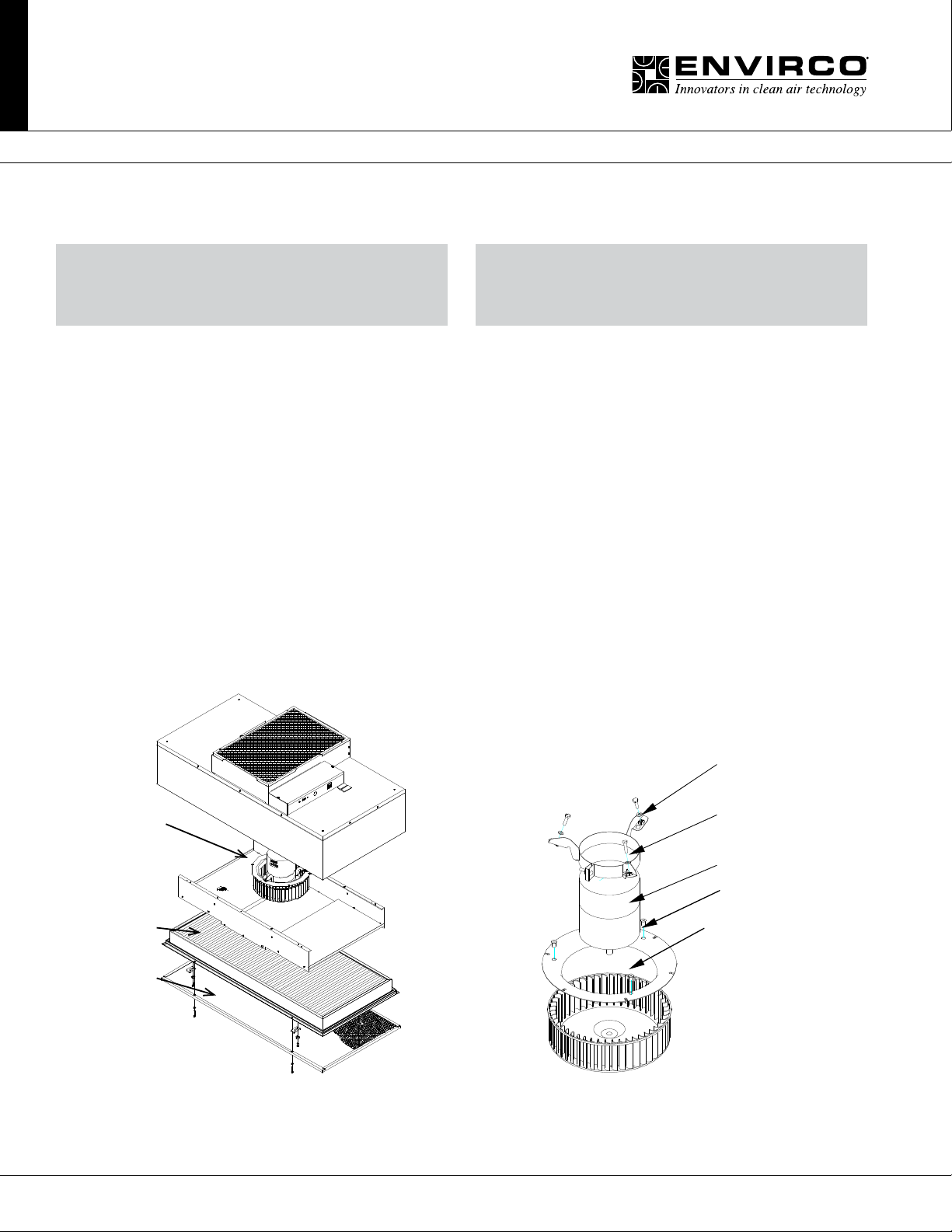
Electrical connectors
located in inner
prefilter wall
Plenum
Gel Seal Filter
Motor/Blower
Assy
Blower
Wheel
Venturi
Ring
Motor
Machine Screw
and washer
Grommet
Wellnut
Screen
Fan Filter Unit
Installation & Service Manual
■ Service: RSR/E Motor Removal and Installation
WARNING
DISCONNECT THE UNIT FROM THE ELECTRICAL
POWER SOURCE BEFORE ATTEMPTING
ANY SERVICE
Note: Minimum 2 person project.
Tools Required: 3/16 Ball Driver, Phillips screw bit, Head Driver, Battery Operated Drill, (2) 8” adjustable wrenches, 10 mm
hex head wrench, #2 standard screwdriver, and slip joint pliers
Step 1. To gain access to the motor, remove the gel seal lter.
Step 2. Prior to removing motor/blower assembly, remove blower wheel to expose motor connectors on motor. Using an
adjustable wrench loosen the two set screws that attach the blower wheel to the motor shaft. Disconnect the ve and sixteen
pin connectors from the motor.
Step 3. While supporting the motor blower assembly from below, remove the six screws on the underside of the venturi ring
and lower the assembly. (See Figure 7). Note the bafe does not have to be removed to remove the motor/blower assembly.
Step 4. Before removal of the motor mount bracket, measure the precise location of the bracket on the motor. Remove the
bracket.
Step 5. Replace with the new motor and reassemble by reversing the above steps. Set the location of the motor mount
bracket as measured (see above Step 6). Set the spacing at 0.25” (6.35 mm) clearance between the blower and the upper
motor plate/prelter frame creating a 0.11” (2.80 mm) overlap between the wheel and the venturi ring. When reinstalling the
assembly, align the plate to insure that the leads will reach the electrical box.
ELECTRICAL SERVICE SHOULD ONLY
BE PERFORMED BY A LICENSED
OR QUALIFIED ELECTRICIAN.
WARNING
18 Innovators in Clean Air Technology | www.envirco.com | Operation & Maintenance
Motor/Electrical Removal Motor Assembly
Page 19
MAC 10® IQ
Fan Filter Unit
Installation & Service Manual
TN1004
Changing from GE to Nidec Motors in the Field
TECHNICAL NOTES
■
Changing out from GE 2.3 to Nidec PerfectSpeed DC Motors in the eld
The Envirco DC family of Fan Filter Units has previously used the GE 2.3 motor that was purchased
by Regal Beloit. The older models have GE 2.3 motors that have become obsolete and are replaced
with the new Regal Beloit model EON. The EON motor is currently being evaluated and you will be
receiving a new manufactured motor named Nidec PerfectSpeed.
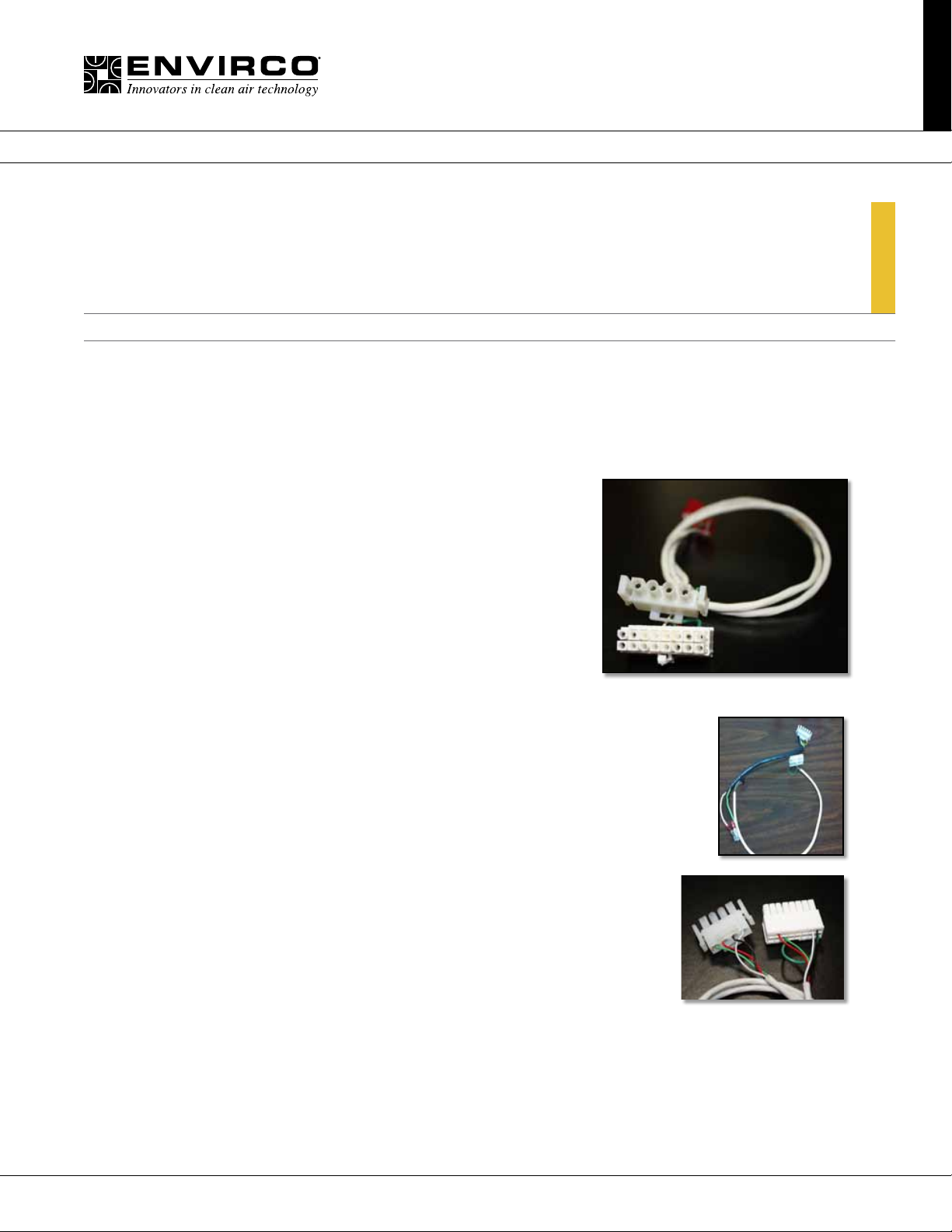
When you order a replacement motor they will be a form and t
replacement, except for the cable that connects to the control
board and the motor. The new Nidec motor will require you to
replace the cable. The old cable was a sixteen pin connector
while the new motor cable will have a four pin connector as
shown in the photo to the right.
Please use the new cable with the new four pin connector to
connect your new motor. The cable number will be determined
by the build style of your unit.
■
Nidec Part References
18 in Standard Build 63751-015
12 in RSRE Build 63751-016
15 ft Whip 63751-017
■
Old Cable References
The power cable, has remained the same for the new motor and will be reused.
The rest of the t and function will be a direct replacement. Follow the procedure
in the IOM for motor swap for your particular FFU.
■
Contact Us
Contact Envirco sales or technical team for any assistance needed.
New Cable Style
Old Cable Style
Old Cable Style
Note: GE 2.3 motors are obsolete.
19Innovators in Clean Air Technology | www.envirco.com | Operation & Maintenance
Page 20
MAC 10® IQ
Fan Filter Unit
Installation & Service Manual
TN1004
Changing from GE to Nidec Motors in the Field
■
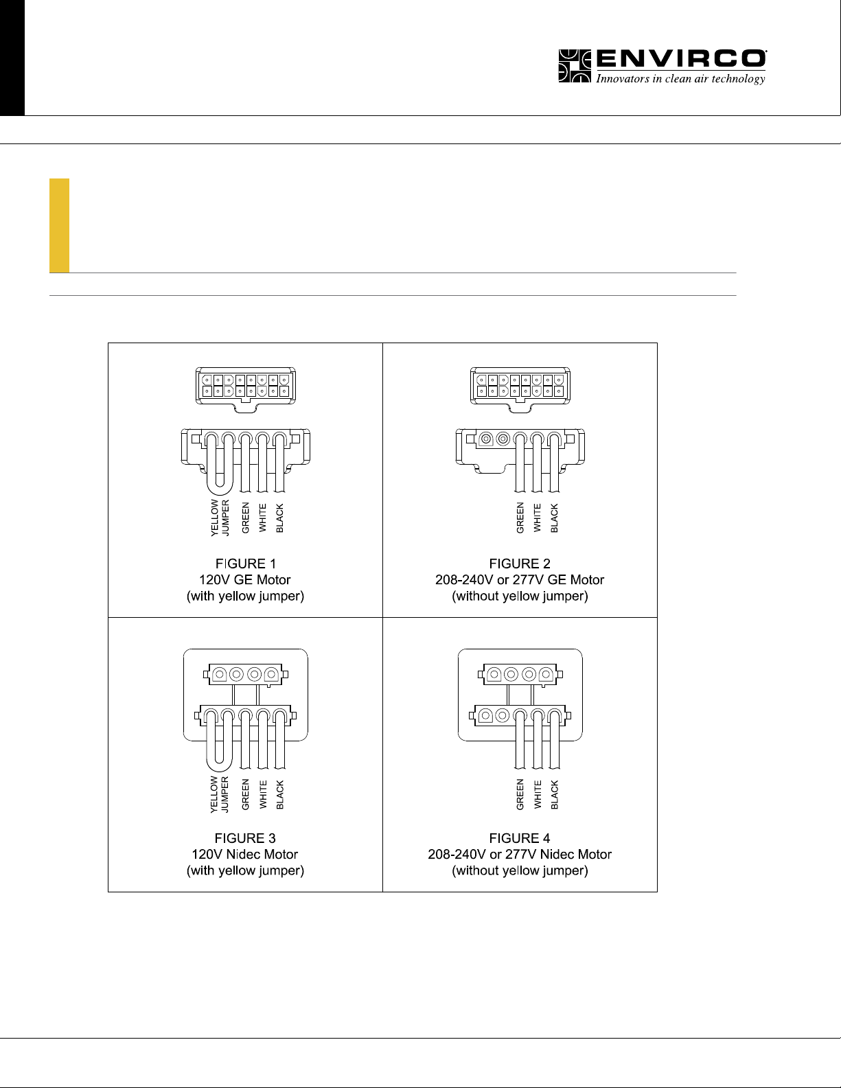
MAC 10 Motor Cable Congurations
TECHNICAL NOTES
20 Innovators in Clean Air Technology | www.envirco.com | Operation & Maintenance
Page 21

MAC 10® IQ
Fan Filter Unit
Installation & Service Manual
TN1002
MAC10® Design with VAV Boxes
TECHNICAL NOTES
■
MAC 10 designs with Duct Collar, VAV or constant air box and fan coils
For applications requiring powered fan lter units and a ducted connection our recommendations
would be to use the MAC10 LEDC (ECM motor) or Mac10 Original ( PSC motor)
■
Feature
» MAC10 LEDC
- Power conservation and high airow
» MAC10 Original
- Lower unit cost
■
Caution
» MAC10 IQ is not recommend for the above design
For applications when you use a VAV box or Constant Airow Terminal, Duct Collars or Fan
coils. The design engineer must advise the contractor or air balancer that the air supply
needs to be balanced. If you do not balance the air supply properly you have the potential
to starve or over feed the fan with air causing the motor to stall which can damage the fan
motor. This also can be minimized by notifying Envirco beforehand for assistance. The ECM
motors used in the IQ design are a Microprocessor controlled motor and are designed to
maintain a constant air volume. When two controllers are compensating the air volume at
the same time, the motor microprocessor is unable to stabilize the airow and will shut itself
down if it cannot nd a stable operating point.
In addition to properly balancing the airow to the Fan: you should prepare a sequence of
operations turning on FFU’s prior to energizing the Air Handler to prevent potential backward
rotation of the blower wheel which can prevent motor rotating in the proper direction and will
reduce airow and cause eventual shutdown. The drive components inside the ECM motors
are self-testing and sized for the motor being used inside the unit they can’t compete with the
airows from a duct blower motor.
21Innovators in Clean Air Technology | www.envirco.com | Operation & Maintenance
Page 22
MAC 10® IQ
Fan Filter Unit
■ Wiring Diagrams
Installation & Service Manual
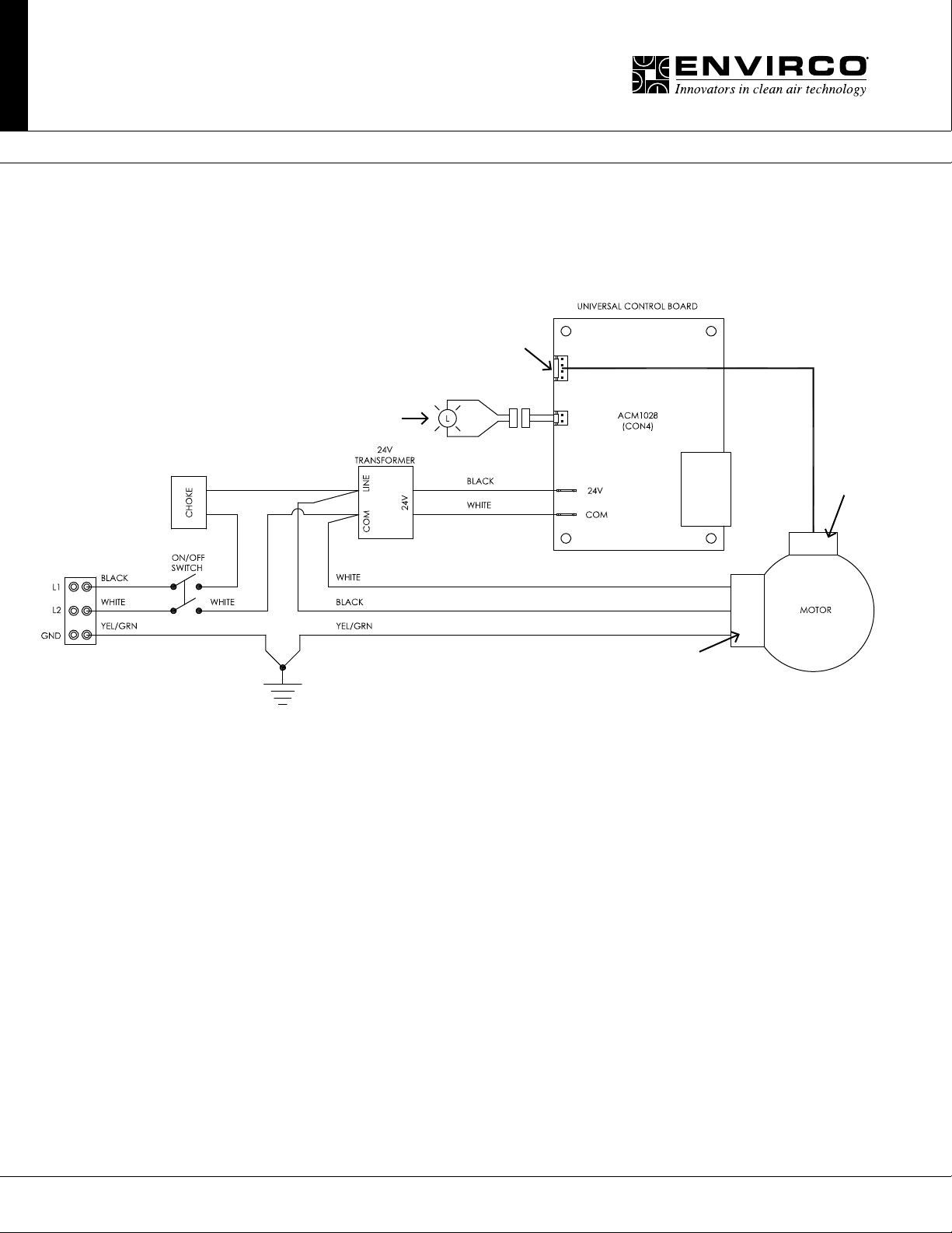
4 Pin MTA
Motor Connector
Remote Run
Indicator LED
4 pin
Control
Cable
Universal Card Wiring Diagram
5 pin
Power
Cable
22 Innovators in Clean Air Technology | www.envirco.com | Operation & Maintenance
Page 23
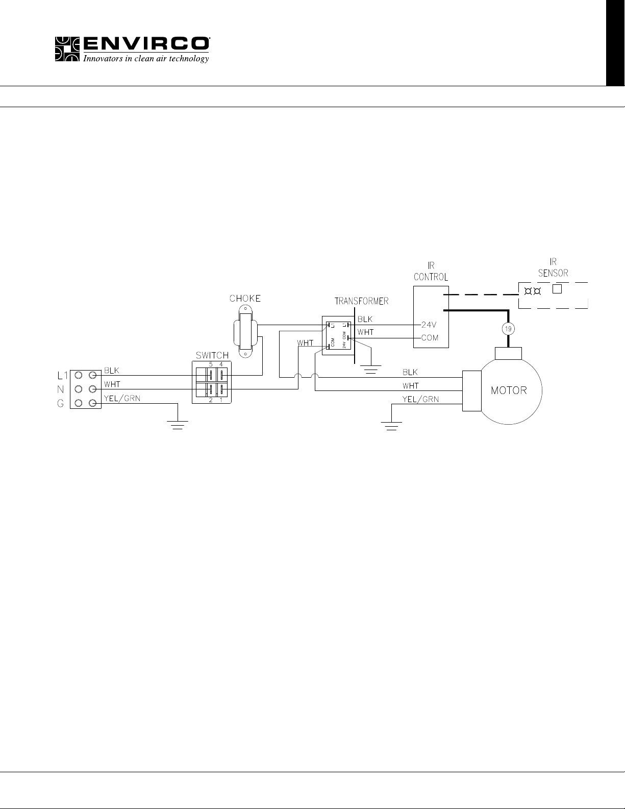
■ Wiring Diagrams
MAC 10® IQ
Fan Filter Unit
Installation & Service Manual
Infrared Control
23Innovators in Clean Air Technology | www.envirco.com | Operation & Maintenance
Page 24
MAC 10® IQ
Fan Filter Unit
Installation & Service Manual
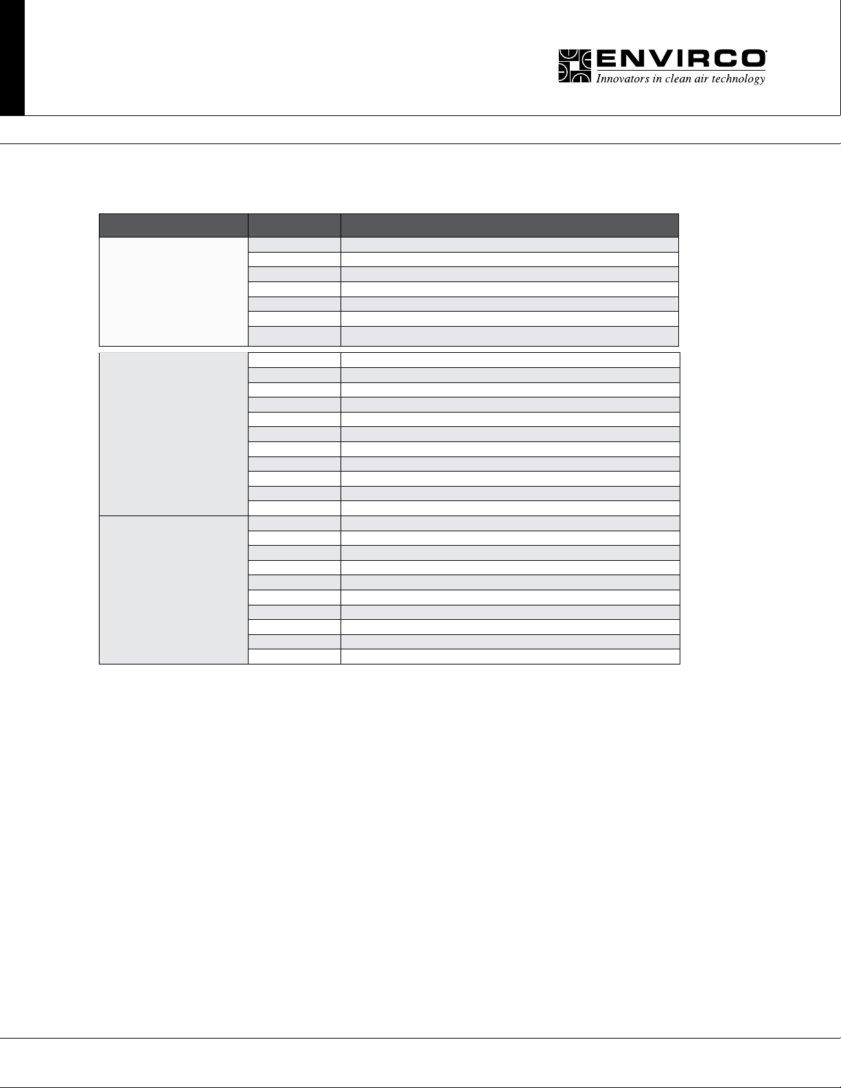
■ Replacement Parts List
Model Part Number Description
63739-002 Switch, Rocker Dpst Wht/Wht
63752-001 IQ Motor Harness, 5-pin 120v 15” LONG (W/ YEL JUMPER), STD, RSR
38532-001 Deector - Filter, 2x4
MAC 10 IQ
MAC 10 STD IQ
MAC 10 STD IQ / NIDEC
62968 Gasket, Neop .125x.5
63388 Grommet 5/8 Id 1 1/8 Od
94800-001 Carton, MAC10
94801-014 Insert, Cardboard
24397-017 Motor - ECM 1/2 HP (Programmed Installed) 2x4 120/240V
24397-018 Motor - ECM 1/2 HP (Programmed Installed) 2x4 277V
24397-003 Motor - ECM 1/2 HP (Programmed Installed) 2x2 120/240V
24397-004 Motor - ECM 1/2 HP (Programmed Installed) 2x2 277V
63655-001 277V Motor 1/3 HP 1650 RPM ECM
63951-002 Visual Speed Control
63970 MOD BUS Control 1004
63270 Blower Wheel Poly
62964 Venturi Ring
265888 Universal Card
63970-003 MODBUS Card 1014.1.32 REV
S266587-007 2x4 Motor Asm 120/240V - Nidec
S266587-008 2x4 Motor Asm 277V - Nidec
S266587-009 2x3 Motor Asm 120/240V - Nidec
S266587-010 2x3 Motor Asm 277V - Nidec
63720 Choke 3.0 Amps
63677 Transformer 120VP 24V 2ND
63666 Transformer 220VP 24V 2ND
63665 Transformer 277VP 24V 2ND
63759-001 IR Sensor Harness
63758 IR Sensor without Harness
24 Innovators in Clean Air Technology | www.envirco.com | Operation & Maintenance
Page 25
MAC 10® IQ
Fan Filter Unit
Installation & Service Manual
~ PRODUCTION RELEASE;ECN-52102 RCH 7/26/13
25Innovators in Clean Air Technology | www.envirco.com | Operation & Maintenance
Page 26
MAC 10® IQ
Fan Filter Unit
~ PRODUCTION RELEASE;ECN-52102 RCH 7/29/13
Installation & Service Manual
26 Innovators in Clean Air Technology | www.envirco.com | Operation & Maintenance
Page 27

Installation & Service Manual
MAC 10® IQ
Fan Filter Unit
■ Limted Warranty
LIMITED WARRANTY: Unless otherwise expressly stated
in Envirco’s published specifications for the Goods, Envirco
warrants that Goods are free from defects in material and
workmanship, except for services which are warranted to be
performed in a competent and diligent manner in accordance
with any mutually agreed specifications. The foregoing
warranty shall apply for eighteen (18) months from the date
of shipment from Envirco’s facility, except for services for
which the warranty shall apply for ninety (90) days from
the date of performance (the “Warranty Period”). Provided
Buyer informs Envirco in writing of any breach of warranty
prior to the expiration of the applicable Warranty Period,
Envirco shall, as its sole obligation and Buyer’s sole and
exclusive remedy for any breach of this warranty, repair or
replace/re-perform the Goods which gave rise to the breach
or, at Envirco’ option, refund the amounts paid by Buyer
for the Goods which gave rise to the breach. Any repair,
replacement or re-performance by Envirco hereunder shall
not extend the applicable Warranty Period. The parties shall
mutually agree on the specifications of any test to determine
the presence of a defect. Unless otherwise agreed upon by
Envirco in writing, Buyer shall bear the costs of access, deinstallation, re-installation and transportation of Goods to
Envirco and back to Buyer. These warranties and remedies
are conditioned upon (a) the proper storage, installation,
operation, and maintenance of the Goods and conformance
with the proper operation instruction manuals provided by
Envirco or its suppliers or subcontractors, (b) Buyer keeping
proper records of operation and maintenance during the
applicable Warranty Period and providing Envirco access to
those records, and (c) modification or repair of the Goods
only as authorized by Envirco. Envirco does not warrant the
Goods or any repaired or replacement parts against normal
wear and tear or damage caused by misuse, accident, or
use against the instructions of Envirco. Any modification or
repair of any of the Goods not authorized by Envirco shall
render the warranty null and void. EXCEPT AS EXPRESSLY
SET FORTH HEREIN, ENVIRCO MAKES NO OTHER
WARRANTIES, EXPRESS OR IMPLIED, INCLUDING,
BUT NOT LIMITED TO, ANY IMPLIED WARRANTIES
OF MERCHANTABILITY, NON-INFRINGEMENT OR
FITNESS FOR A PARTICULAR PURPOSE WHICH ARE
HEREBY DISCLAIMED TO THE EXTENT PERMITTED BY
APPLICABLE LAW.
■ Testing
Each MAC 10 IQ filter unit is thoroughly tested at the factory
before shipment. However, because of the “rigors” of
shipping, ENVIRCO encourages its re-test after installation.
ENVIRCO recommends that the customer contact an
independent organization, with technicians trained and
experienced in performance evaluation and maintenance of
clean air equipment.
HEPA filters (Type J) are tested to IEST-RP-00034. ULPA
filters are tested to (Type F) IEST-RP-00034. All filters are UL
900 recognized. Your filters may have special requirements,
please see original engineering specifications for you specific
project.
All units that are airflow tested at Envirco are tested using a
Shortridge Airdata Multimeter 870 with a Velgrid head. The
recommended method of reading is to place one corner of
the Velgrid head 1-1/4” from the corner of the filter face and
then take four reading evenly spaced along the four foot side,
then repeat these reads three additional times. This gives a
total of 8 reading to test the unit. All advertised data is based
on using the Velgrid with 8 readings (128 velocity points).
Envirco recognized the using 8 reading during a cleanroom
start-up may be time consuming and recommends using
4 Velgrid readings taken on each 2x2 filter section will
approximate the same as 8 readings.
Additional independent testing on the Envirco Mac 10 IQ 2x4,
2x2, and 2x3, shows that using one-2x4 or two-2x2 hoods
simultaneously give airflow data (cfm) with 5 percent of a
duct traverse using 10 diameters of straight duct upstream
of the fan intake.
27Innovators in Clean Air Technology | www.envirco.com | Operation & Maintenance
Page 28

Clean air solutions built for you.
MORE INFORMATION AVAILABLE AT WWW.ENVIRCO.COM
Industrial
Cleanroom Products
®
» MAC 10
» MAC 10
» MAC 10
» MAC 10
» Ducted Ceiling Module:
DCM & RSR
» AC or DC Control Systems
Original
®
IQ™
®
LEAC™
®
LEDC™
Hospital & Healthcare
Hospital & Healthcare
®
» IsoClean
with Ultraviolet Light
» AirCeil
» Hospi-Gard® Room
Pressure Monitor
Enviramedic Products
» HOR Horizontal Flow
Enclosure
» HCF Horizontal Flow
Surgery Room
» VOR Vertical Flow Surgery
Isolator
and IsoClean
®
Pharmaceutical
Pharmaceutical &
Medical Device
®
» MAC 10
are available in stainless
steel diffuser screens or
complete stainless steel
construction
» Unimodule M-2 Vertical
Unidirectional Flow
Workstation
» METD 100% Exhausted
Vertical Flow Workstation
» Unidirectional Downow
RX products
Laboratory & Research
Laboratory & Research
» 100-Plus Horizontal or
Vertical Flow Clean Bench
» Unidirectional Flow
Horizontal Flow Bench (LF)
» TT Table Top Horizontal
Flow Clean Bench
» EnviraLab Sterility Module:
ESM
» NSF 49 Listed Biological
Safety Cabinet
Module
Envirco MAC 10 and VE5 are registered trademarks of Envirco, USA. Specications subject to modications or changes without notice. US patents 4,560,395 and 5,470,363. Other patents issued and pending in
foreign countries. Special thanks to Connect2Cleanrooms for cleanroom photography.
Envirco USA
101 McNeill Road | Sanford, NC 27330, USA
tel: 919.775.2201 | toll free: 800.884.0002 | fax:800.458.2379
www.envirco.com | email: [email protected]
Form P/N#: 267336 Rev 0614
Envirco European Sales
The Cavendish Centre, Winnall Close | Winchester, Hampshire; S023 OLB, UK
tel:+44(0)1962.840465 | fax:+44(0)1962.828619
www.envirco-emea.com | email: r[email protected]
Envirco Asian Sales and Manufacturing
Building #1, 200 Middle Suhong Road | Suzhou, Jiangsu PRC 215021
tel: +86.512.62587180 | fax: +86.512.62580031
www.envirco.com | email: [email protected]Copyright ©2014 Envirco. All Rights Reserved.
 Loading...