

Page 1
OPERATION & MAINTENANCE MANUAL
Envirco Technical Support: 800-884-0002
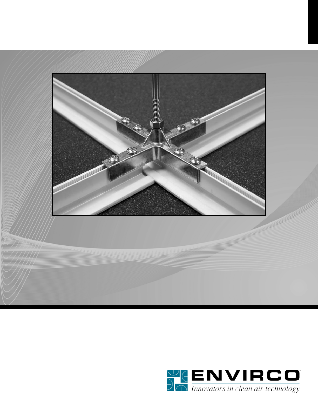
MAC-T Ceiling Grid System
2” Heavy Duty for Cleanroom
Page 2

MAC-T Ceiling Grid System
2” Heavy Duty for Cleanroom
Installation & Service Manual
Table of Contents
Introduction ....................................................................................................................... 3
Tools ................................................................................................................................. 3
Uncrating, Inspection, and Inventory ................................................................................ 3
Notes ................................................................................................................................ 3
Part Numbers & Extrusion Guide Description .................................................................. 4
Diagram ............................................................................................................................ 5
Installation ........................................................................................................................ 6
Maintenance ..................................................................................................................... 7
Please read through instructions before beginning installation.
2 Innovators in Clean Air Technology | www.envirco.com | Operation & Maintenance
Page 3

MAC-T Ceiling Grid System
2” Heavy Duty for Cleanroom
Installation & Service Manual
■ Introduction
Envirco offers the T-Grid 2” Gasket Seal Grid Cleanroom Ceiling System with superior materials that provides a structural grid
system and zinc alloy die-castings. The materials are packaged with care, but check for damage that may have occurred during
transit. Please inspect the shipment and quantity before beginning installation. Please notify us promptly if you experience any
problems at 800.884.0002.
The following information is provided by Envirco as a general guideline for the installation of the 2” T-Grid cleanroom ceiling
grid system. This information should be reviewed prior to commencing installation. The intent is to be as specic as possible
in detail for a typical project, yet general enough to be utilized by most installations. It is Envirco’s intent that the descriptions
are helpful and easy to understand. If there are any questions, comments, or special considerations, please contact Envirco
Technical Support at 800.884.0002.
Note: This narrative assumes that the job-site is clear and ready for the construction of cleanroom ceiling.
■ Tools
It is suggested that the following tools be used to erect this system:
• Laser or Suitable Leveling Instrument
• Phillips head Drive & Cordless Drill
• Circular Saw with Fine Toothed Carbide Tip Blade
• (triple toothed, negative rake, aluminum blade)
• Miter Saw with Fine Toothed Carbide Tip Blade
• (triple toothed, negative rake, aluminum blade)
■ Uncrating, Inspection, and Inventory
The Envirco ceiling system is packaged in the factory in a manner to protect each part during normal shipping and handling. It
is recommended by Envirco that the original packaging remain intact as much as possible until the individual parts are needed.
All extrusion components are packaged in boxes with protective paper between nished surfaces.
As the skids are received at the job-site, they should be placed in a location near the installation area, where they will not
become an obstacle, or require to be moved at a later time. The skids should then be opened, however leaving the internal
packaging unchanged. Pieces should be removed on an as needed basis and the packaging discarded. At this time, however,
the components should be visually inspected for obvious damage and an inventory taken to conrm that all parts are received
in good condition. Notify Envirco immediately of any discrepancies in quantity.
■ Fasteners Not Provided by Envirco
Envirco does not provide the attachment hardware for the existing structure or framework. All hardware required from the
turnbuckle to the existing support structure is not provided.
■ Special Notes
Due to expansion and contraction properties of aluminum, it is recommended that this system be installed in a temperature
that is as close as possible to that which the nished room will operate. Stock T-bar or wall angle with a length of over 4 feet is
cut with a tolerance of +/-.032”. Stock cross-tees less than 4 feet is cut to +/- .016”. The above stated tolerances are measured
at a material temperature of from 60 to 90 F. All eld cuts including perimeter miter cuts are to be performed by the installing
contractor.
3Innovators in Clean Air Technology | www.envirco.com | Operation & Maintenance
Page 4
MAC-T Ceiling Grid System
ECN-52076A.
DESCRIPTION
DATE
RCH
7/25/13
PART NO. 267324-007
DATE
RCH
7/25/13
PART NO. 267324-003
PART NO. 267324-001
PART NO. 267324-003
ECN-52076A.
A
RCH
PART NO. 267324-003
PART NO. 267324-007
PART NO. 267324-008
PART NO. 267324-009
1:2
1/1
267324-XXX
T-GRID CEILING HARDWARE
SHEET
REV
TITLE
DWG
R
SCALE
A
REV.
DESCRIPTION
DATE
RCH
7/25/13
ECN-52076A.
A
RCH
PART NO. 267324-003
PART NO. 267324-007
PART NO. 267324-008
REV.
DESCRIPTION
DATE
RCH
7/25/13
2” Heavy Duty for Cleanroom
Installation & Service Manual
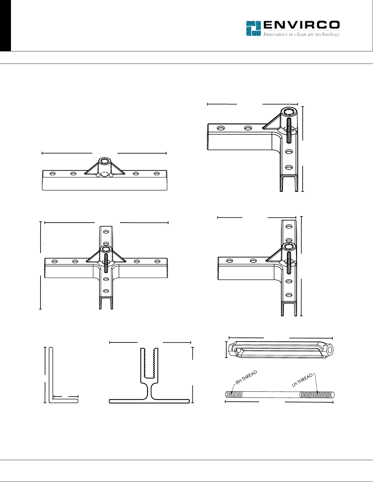
■ Part Numbers and Extrusion Guide
Identify various parts from reference drawings on Page 5.
3.300
5.975
5.975
P/N: 267324-007 P/N: 267324-008
5.975
P/N: 267324-001
3.300
P/N: 267324-002
3.300
5.975
1.97
6.875
.812
2
1.38
P/N: 267324-003
2.00
2.75
1
P/N: 267322-007 P/N: 267322-001
P/N: 267324-004
4 Innovators in Clean Air Technology | www.envirco.com | Operation & Maintenance
8.00
Page 5
■ Diagram
MAC-T Ceiling Grid System
2” Heavy Duty for Cleanroom
Installation & Service Manual
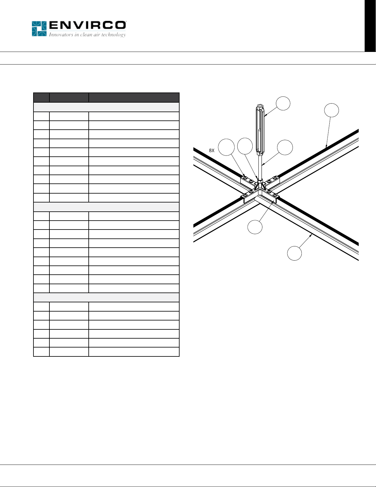
# P/N Description
MAC 10 T-GRID COMPONENTS
1 267322-001 MT240-Main Runner 20ft
1 267322-002 MT240-Main Runner 10ft
1 267322-003 MT240-Main Runner 8ft
1 267322-004 MT240-Main Runner 6ft
2 267322-005 CT46.5 Cross Tee 46.5”
2 267322-006 CG22.5 Cross Tee 22.5”
2 267322-007 1 X 2 Wall Angle 10ft
2 267322-008 1 X 2 Wall Angle 20ft
NS 267322-009 Gasket Tgc 50ft
2 267322-010 Main Splice Tgc (12ft)
MAC 10 T-GRID HARDWARE - CONNECTIONS
3 267324-001 Cast 4 Way Connector
3 267324-002 Cast 3 Way Connector
4 267324-003 Turnbuckle 3/8-16x7
5 267324-004 Rod, 16 Thread x 3/8” X 8”
6 267324-005 Screw 1/4-20x3/4 Phms
7 267324-006 Nut 3/8-16 Hex
3 267324-007 Cast 2 Way Connector
NS 267324-008 Corner Cast 2 Way
NS 267324-009 Eyebolt W/nut 3/8”
MAC 10 T-GRID HARDWARE - LIGHTING
NS 267325-001 120v Light 2x4 T-bar, 4 Tube
NS 267325-002 230v Light 2x4 T-bar, 4 Tube
NS 267325-003 277v Light 2x4 T-bar, 4 Tube
NS 267325-004 120v Light 1x4 Surface, 2 Tube
NS 267325-005 230v Light 1x4 Surface, 2 Tube
NS 267325-006 277v Light 1x4 Surface, 2 Tube
4
2
6
7
5
3
1
NS=Not Shown.
5Innovators in Clean Air Technology | www.envirco.com | Operation & Maintenance
Page 6

MAC-T Ceiling Grid System
2” Heavy Duty for Cleanroom
Installation & Service Manual
■ Installation of Wall Angle
The rst component to be installed is the wall angle. Attach lengths of wall angle to walls using appropriate fasteners for the
type of existing wall. It is advisable to pick one wall as a starting point and begin attaching wall angle from the center of the
wall towards the corners. A laser or other suitable leveling tool should be used to assure a consistently level nished product.
Continue attaching wall angle around walls and columns, if any, until complete. The wall angle sections are connected at the
intersections with appropriate fastener into the existing wall.
■ Wall Angle at Corners
The wall angle is to be cut using a miter saw (with the proper cutting blade) at 45 degrees in the eld by the installation team
to create corners.
■ Installation of T-Bar
Once the wall angle is installed, the rest of the grid installation can begin. The extruded aluminum sections are connected at
the intersections with the 4-way zinc alloy die castings. The bottom of this casting has an open face channel that embraces
the top extruded screw boss of the main runners and cross bar sections. The castings are bolted to the extrusion with 1⁄4-20 x
3/4” full threaded Phillips head cap screws. This is most easily done with a power drill or other such tool. The grid is suspended
with 3/8”-16 threaded rod for which the castings are already tapped.
The castings will accept a special right hand/left hand (RH-LH) threaded rod to allow for use with turnbuckles. The RH-LH
threaded rod should be turned into the casting and “bottom out” on the main runner. Turnbuckles are not a requirement for
secure suspension. However, in that case, some other means of leveling the grid system should be used.
Hang all of the threaded rods, turnbuckles and castings at the appropriate 2’ x 4’ or 4’ x 4’ centers (nominal) and then bolt
main runners (12’) lengths into place. The cross tees may then be bolted in using a 24 1⁄2” x 48 1⁄2” on center conguration.
(This may vary depending on your grid layout).
■ Installation of Gasket
The gasket should come factory applied. If it does not, perform the following. The Envirco system provideds 1/8” x 3/8” gasket
tape is usually applied to the extruded grid members prior to installation. After unpacking the part, the surface of the extrusion
is cleaned using a solution of isopropyl alcohol and water. The gasket tape is then applied with the adhesive side down, leaving
approximately 3/4” to 1” extra gasket material on each end of the cross tees to allow for a proper seal of the gaskets at the
grid intersection.
6 Innovators in Clean Air Technology | www.envirco.com | Operation & Maintenance
Page 7

MAC-T Ceiling Grid System
2” Heavy Duty for Cleanroom
Installation & Service Manual
■ Installation of Light and Filter Fixtures
Once the ceiling grid is installed, the xture installation can begin. If “lay-in” light xtures are to be used, they should be installed
rst in order to make the wiring easier. Once the light xtures are in place and wired, the lter modules can be installed. This is
done by pushing the lter xture through the grid at an angle and then lowering them until they nest in place. After all the lter
modules are in place, the blank ceiling panels are installed. Installation of Ceiling Tiles Blank panels are placed in the grid
opening after the gasket is in place. Special cuts can be made by measuring from the center line of the grid and deducting 7/8”
from that dimension, (see chart below). For example, a 24 1/2” x 48 1/2” grid centerline would take a blank 23 5/8” x 47 5/8”
in size. If the blank panel hold down clips are utilized, a minimum of six (6) clips per 2’ x 4’ blank panel are required. The clips
are secured to the T-Grid extrusions utilizing a 1⁄4”-20 bolt.
Center Line of Grid - 24 1⁄2” x 48 1⁄2”
Module, Fixture, and Ceiling Tile Size - 23 5/8”x 47 5/8”
CAUTION: Be extremely careful when installing HEPA lters. Be careful not to touch the face of the lter (bottom of
the xture). This can cause damage to the HEPA lter unit and may need replacing.
■ Sealing Wall Angle
This is a simple process utilizing an approved construction sealant. A bead of sealant is placed at the corner of the wall angle
and existing wall on the room side. The sealant should be applied to assure an airtight seal.
■ Maintenance
Prior to completing the installation, a nal inspection and wipe-down should take place. Wipe the panels and extrusions with
an approved cleanroom alcohol wipe. If any chemicals are to be utilized, spot check with extra materials prior to use to insure
that the nish of the wall system is not damaged.
Cleaning of the Envirco MAC-T Ceiling Grid requires the use of non-shedding, cleanroom approved wipers and a solvent of
isopropyl alcohol diluted with distilled water.
7Innovators in Clean Air Technology | www.envirco.com | Operation & Maintenance
Page 8

Clean air solutions built for you.
MORE INFORMATION AVAILABLE AT WWW.ENVIRCO.COM
Industrial
Cleanroom Products
®
» MAC 10
» MAC 10
» MAC 10
» MAC 10
» Ducted Ceiling Module:
DCM & RSR
» AC or DC Control Systems
Original
®
IQ™
®
LEAC™
®
LEDC™
Hospital & Healthcare
Hospital & Healthcare
®
» IsoClean
with Ultraviolet Light
» AirCeil
» Hospi-Gard® Room
Pressure Monitor
Enviramedic Products
» HOR Horizontal Flow
Enclosure
» HCF Horizontal Flow
Surgery Room
» VOR Vertical Flow Surgery
Isolator
and IsoClean
®
Pharmaceutical
Pharmaceutical &
Medical Device
®
» MAC 10
are available in stainless
steel diffuser screens or
complete stainless steel
construction
» Unimodule M-2 Vertical
Unidirectional Flow
Workstation
» METD 100% Exhausted
Vertical Flow Workstation
» Unidirectional Downow
RX products
Laboratory & Research
Laboratory & Research
» 100-Plus Horizontal or
Vertical Flow Clean Bench
» Unidirectional Flow
Horizontal Flow Bench (LF)
» TT Table Top Horizontal
Flow Clean Bench
» EnviraLab Sterility Module:
ESM
» NSF 49 Listed Biological
Safety Cabinet
Module
Envirco MAC 10 and VE5 are registered trademarks of Envirco, USA. Specications subject to modications or changes without notice. US patents 4,560,395 and 5,470,363. Other patents issued and pending in
foreign countries. Special thanks to Connect2Cleanrooms for cleanroom photography.
Envirco USA
101 McNeill Road | Sanford, NC 27330, USA
tel: 919.775.2201 | toll free: 800.884.0002 | fax:800.458.2379
www.envirco.com | email: [email protected]
Form P/N#: 267338-001
Envirco European Sales
The Cavendish Centre, Winnall Close | Winchester, Hampshire; S023 OLB, UK
tel:+44(0)1962.840465 | fax:+44(0)1962.828619
www.envirco-emea.com | email: r[email protected]
Envirco Asian Sales and Manufacturing
Building #1, 200 Middle Suhong Road | Suzhou, Jiangsu PRC 215021
tel: +86.512.62587180 | fax: +86.512.62580031
www.envirco.com | email: [email protected]Copyright ©2013 Envirco. All Rights Reserved.
 Loading...